Loading ...
Loading ...
Loading ...
Please refer to the technical
instructions on how to adjust the hob
to the gas specifications on Malta.
This appliance is certified for Malta.
Make sure that, once the hob is installed, it is easily
accessible for the engineer in the event of a
breakdown.
The manufacturer will not accept liability, should the
above instructions or any of the other safety
instructions incorporated in this instruction booklet
be ignored.
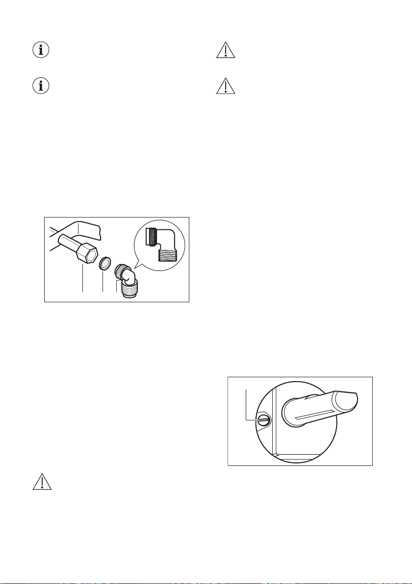
On the end of the shaft, which includes the R 1/2"
threaded elbow, adjustment is fixed so that the
washer is fitted between the components as shown
in the diagram. Screw the parts together without
using excessive force.
A B C
A. End of shaft with nut
B. Washer supplied with the appliance
C. Elbow supplied with the appliance
Connection to the gas supply should be with either
rigid or semi-rigid pipe, i.e. steel or copper.
The connection should be suitable for connecting
to R 1/2 (1/2 BSP male thread).
When the final connection has been made, it is
essential that a thorough leak test is carried out on
the hob and installation.
Make sure that the main connection pipe does not
exert any strain on the hob.
If you use flexible metal pipes make sure that they
agree to ISO 10380 and ISO 10807 standards. Be
careful they do not come in touch with mobile parts
or they are not squeezed. Also be careful when the
hob is put together with an oven.
CAUTION! It is important to install the
elbow correctly, with the shoulder on
the end of the thread, fitted to the hob
connecting pipe.
CAUTION! Failure to ensure the
correct assembly will cause leakage of
gas.
CAUTION! Make sure that the gas
supply pressure of the appliance
obeys the recommended values.
Rigid connection:
Carry out connection by using metal rigid pipes
(copper with mechanical end).
INJECTORS REPLACEMENT
1. Remove the pan supports.
2. Remove the caps and crowns of the burner.
3. With a socket spanner 7 remove the injectors
and replace them with the ones which are
necessary for the type of gas you use (see
table in "Technical Data" chapter).
4. Assemble the parts, follow the same procedure
backwards.
5. Replace the rating plate (it is near the gas
supply pipe) with the one for the new type of
gas supply. You can find this plate in the
package supplied with the appliance.
If the supply gas pressure is changeable or
different from the necessary pressure, you must fit
an applicable pressure adjuster on the gas supply
pipe.
ADJUSTMENT OF MINIMUM LEVEL
To adjust the minimum level of the burners:
1. Light the burner.
2. Turn the knob on the minimum position.
3. Remove the knob.
4. With a thin screwdriver, adjust the bypass
screw position (A).
A
5. If you change:
• from natural gas G20 20 mbar to liquid gas,
fully tighten the bypass screw in.
• from liquid gas to natural gas G20 20 mbar,
undo the bypass screw approximately 1/4
of a turn (1/2 of a turn for Multi Crown
burner).
7
Loading ...
Loading ...
Loading ...