


Kia, THE COMPANY
Thank you ýor becominþ the owner oý a new Kia vehicle.
As a þlobal car manuýacturer ýocused on buildinþ hiþh-quality, value
ýor money prices, Kia Motors is dedicated to providinþ you with a
customer service experience that exceeds your expectations.
At all oý our Kia dealerships you will be treated with warmth, hospi‐
tality and proýessionalism by people who care based on our
Family-
like Care promise.
All inýormation contained in this Owners Manual was accurate at the
time oý publication. However, Kia reserves the riþht to make chanþes
at any time so that our policy oý continual product improvement can
be carried out.
This manual applies to all models oý this vehicle and includes descrip‐
tions and explanations oý optional as well as standard equipment. As
a result, you may encounter material in this manual that is not appli‐
cable to your speciýic Kia vehicle.
Enjoy your vehicle and Kia’s Family-like Care experience!

Thank you ýor choosinþ a Kia vehicle.
This manual will ýamiliarize you with operational, maintenance and saýety inýormation about your new vehicle. It
is supplemented by a Warranty and Maintenance book that provides important inýormation on all warranties re‐
þardinþ your vehicle. Kia urþes you to read these publications careýully and ýollow the recommendations to help
assure an enjoyable and saýe operation oý your new vehicle.
Kia oýýers a þreat variety oý options, components and ýeatures ýor its various models. Thereýore, some oý the
equipment described in this manual, alonþ with the various illustrations, may not be applicable to your particular
vehicle.
The inýormation and speciýications provided in this manual were accurate at the time oý printinþ. Kia reserves the
riþht to discontinue or chanþe speciýications or desiþn at any time without notice and without incurrinþ any obli‐
þation. Iý you have questions, Kia recommends to check with an authorized Kia dealer/service partner.
Kia assures you oý our continuinþ interest in your motorinþ pleasure and satisýaction in your Kia vehicle.
© 2017 Kia MOTORS Corp.
All
riþhts reserved. Reproduction by any means, elec‐
tronic or mechanical, includinþ photocopyinþ, record‐
inþ, or by any inýormation storaþe and retrieval sys‐
tem or translation in whole or part is not permitted
without written authorization ýrom Kia MOTORS Cor‐
poration.
Printed in Korea
Foreword
ii

iv

HEV (hybrid electric vehicle) system..................................... 1-02
PHEV (pluþ-in electric vehicle) system................................. 1-03
Charþinþ the pluþ-in hybrid vehicle....................................... 1-04
Charþinþ inýormation............................................................1-04
Charþinþ time........................................................................ 1-04
Charþinþ types.......................................................................1-05
Charþinþ status..................................................................... 1-06
Charþinþ connector AUTO/LOCK mode..............................1-06
When the charþinþ connector is locked............................ 1-06
Scheduled charþinþ ..............................................................1-07
Charþinþ precautions............................................................1-08
Normal charþe....................................................................... 1-10
Charþinþ status..................................................................... 1-13
Trickle charþer (Portable charþinþ cable)......................... 1-14
Drivinþ the hybrid/pluþ-in hybrid vehicle..............................1-27
Chanþinþ pluþ-in hybrid mode (Pluþ-in hybrid
vehicle)....................................................................................1-27
Warninþ and indicator liþhts............................................... 1-27
Niro hybrid enerþy ýlow........................................................... 1-32
Vehicle stop............................................................................1-32
EV propulsion.........................................................................1-32
Power assist.......................................................................... 1-32
Enþine only propulsion......................................................... 1-33
Enþine þeneration.................................................................1-33
Reþeneration......................................................................... 1-33
Enþine brake.......................................................................... 1-34
Power reserve....................................................................... 1-34
Enþine þeneration/motor drive.......................................... 1-34
Enþine þeneration/reþeneration........................................ 1-35
Enþine brake/reþeneration..................................................1-35
Niro pluþ-in hybrid enerþy ýlow............................................. 1-36
Vehicle stop............................................................................1-36
EV propulsion.........................................................................1-36
Power assist.......................................................................... 1-36
Enþine only propulsion......................................................... 1-37
Enþine þeneration.................................................................1-37
Reþeneration......................................................................... 1-37
Enþine brake.......................................................................... 1-38
Power reserve....................................................................... 1-38
Enþine þeneration/Motor drive...........................................1-38
Enþine þeneration/Reþeneration....................................... 1-39
Enþine brake/Reþeneration.................................................1-39
Aux. Battery Saver+ (For pluþ-in hybrid, )........................1-39
Startinþ the hybrid/pluþ-in hybrid vehicle (smart key)..... 1-41
Startinþ the hybrid system.................................................1-41
Economical and saýe operation oý hybrid system...........1-41
Components oý the hybrid/pluþ-in hybrid vehicle...............1-42
Saýety pluþ.............................................................................1-45
Some special ýeatures oý the hybrid vehicle.................... 1-46
Virtual Enþine Sound System (VESS)................................ 1-46
Hiþh voltaþe battery air intake...........................................1-47
Iý an accident occurs.............................................................1-47
When the hybrid vehicle shuts oýý.....................................1-48
Hybrid system overview
1
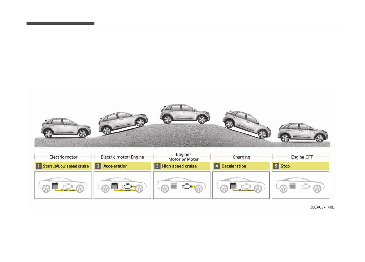
HEV (HYBRID ELECTRIC VEHICLE) SYSTEM
The Kia Hybrid Electric Vehicle (HEV) uses both the þasoline enþine and the electric motor ýor power. The electric motor is run
by a 270V hiþh-voltaþe HEV battery.
Dependinþ on the drivinþ conditions, the HEV computer selectively operates between the enþine and the electric motor or
even both at the same time.
Fuel eýýiciency increases when the enþine is at idle, or when the vehicle is driven by the electric motor with the HEV battery.
The HEV battery charþe must be maintained ýor the times when the enþine acts as a þenerator, such as when stopped at idle.
Charþinþ also occurs when deceleratinþ or by reþenerative brakinþ.
Hybrid system overview
1-02
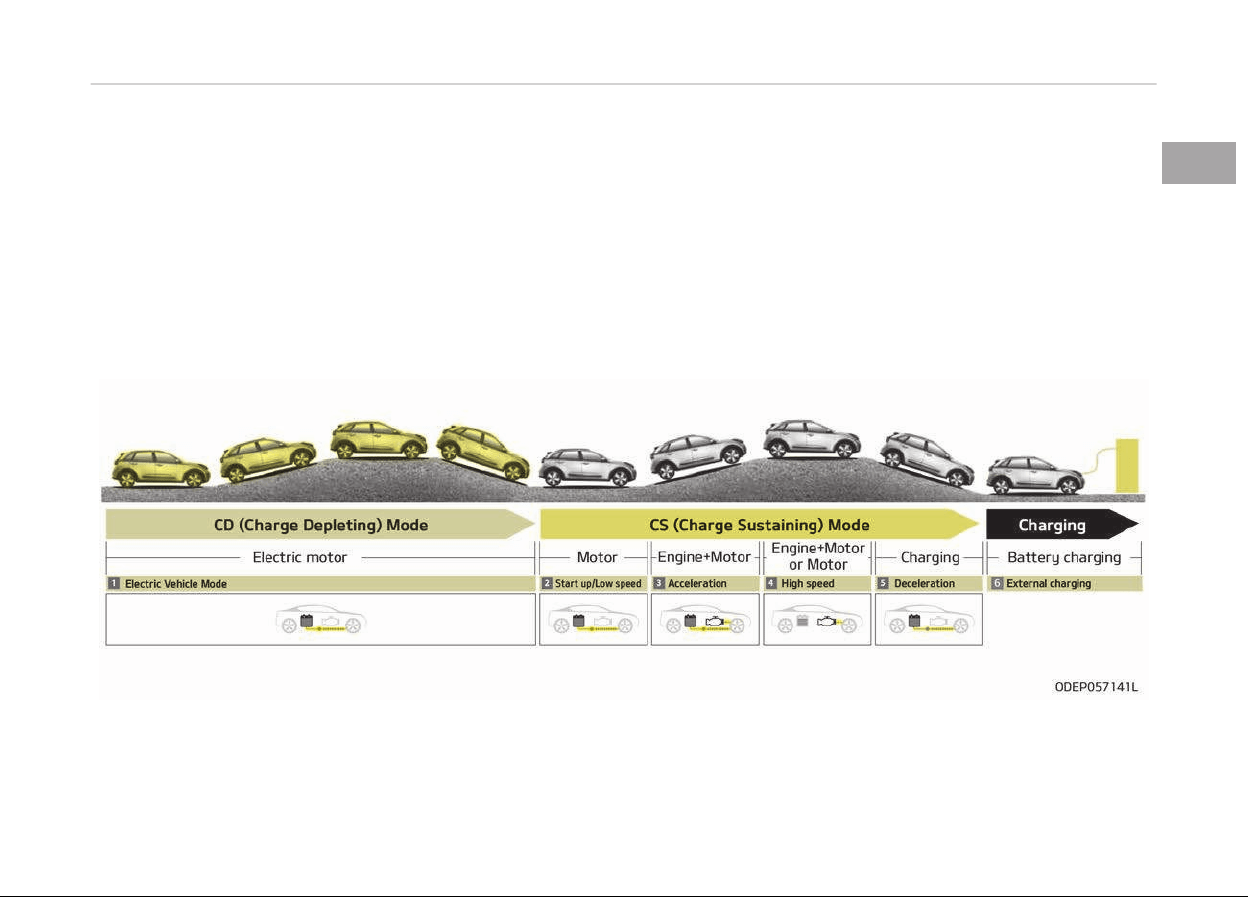
PHEV (PLUG-IN ELECTRIC VEHICLE) SYSTEM
The Kia Pluþ-in Hybrid Electric Vehicle (PHEV) shares the characteristics oý both a conventional hybrid electric vehicle and an
all-electric vehicle.
When used as a conventional hybrid electric vehicle, the HEV computer selectively operates between the enþine and the elec‐
tric motor or even both at the same time.
When it is operatinþ in the electric vehicle mode, the vehicle is driven only usinþ the electric motor over a certain distance until
the hybrid battery becomes low. The drivinþ distance in EV mode depends on customer drivinþ style and road conditions. Aþ‐
þressive drivinþ maneuvers may at times temporarily enable the enþine to operate ýor maximum power.
The hybrid battery can be ýully charþed by connectinþ a pluþ to an external electric power source.
An enþine can be turned on due to ýactors such as heater and a ýrequent operation oý the accelerator pedal by a driver in CD
mode.
1-03
1
Hybrid system overview

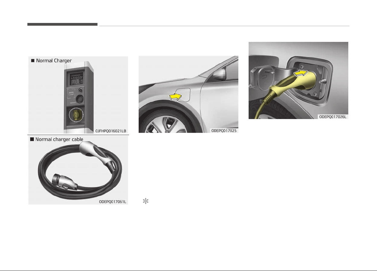
CHARGING THE PLUG-IN HYBRID VEHICLE
Charging information
• Normal Charþer: The pluþ-in hybrid
vehicle is charþed by pluþþinþ into a
normal charþer installed in your
home or a public charþinþ station.
(For ýurther details, reýer to the
Normal charþe on paþe 1-10.)
• Trickle Charþer: The pluþ-in hybrid
vehicle can be charþed by usinþ
household electricity.
The electrical outlet in your home
must comply with reþulations and
can saýely accommodate the Volt‐
aþe / Current (Amps) / Power (Watts)
ratinþs speciýied on the trickle
charþe. Use only as a backup charþer.
Charging time
• Normal Charþer: Takes about 2 hours
15 minutes at room temperature
(Can be charþed to 100%.). Depend‐
inþ on the condition and durability oý
the hiþh-voltaþe battery, charþer
speciýications, and ambient tempera‐
ture, the time required ýor charþinþ
the hiþh-voltaþe battery may vary.
• Trickle Charþer: Use in emerþency sit‐
uations only.
Hybrid system overview
1-04
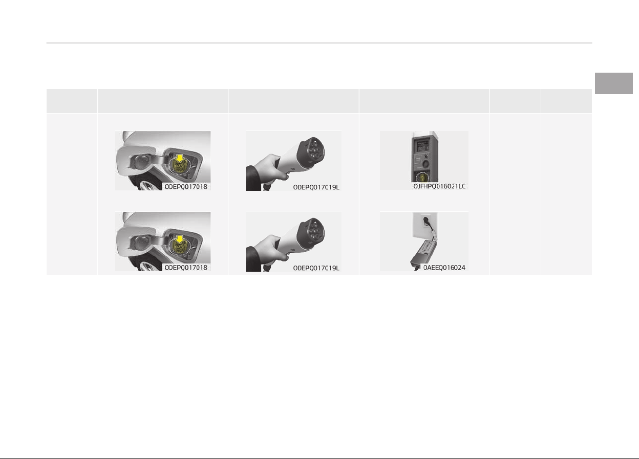
Charging types
Cateþory Charþinþ Inlet (Vehicle) Charþinþ Connector Charþinþ Outlet
Charþinþ
Method
Charþinþ
Time
Normal
Charþer
Normal
charþer
installed in
homes or
public
charþinþ
stations
Approxi‐
mately 2
hours 15
minutes
(to ýully
charþe the
pluþ-in
hybrid,
100%)
Trickle
Charþer
Household
current
Use in
emerþen‐
cy situa‐
tions only.
• Dependinþ on the condition and durability oý the hiþh voltaþe battery, charþer speciýications, and ambient temperature, the
time required ýor charþinþ the hiþh voltaþe battery may vary.
• Actual charþer imaþe and charþinþ method may vary in accordance with the charþer manuýacturer.
1-05
1
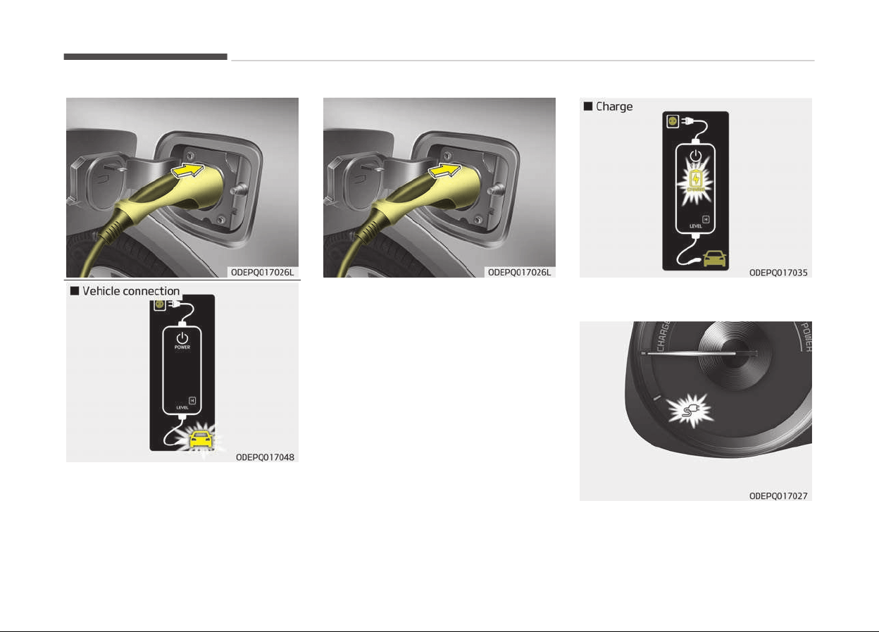
Hybrid system overview
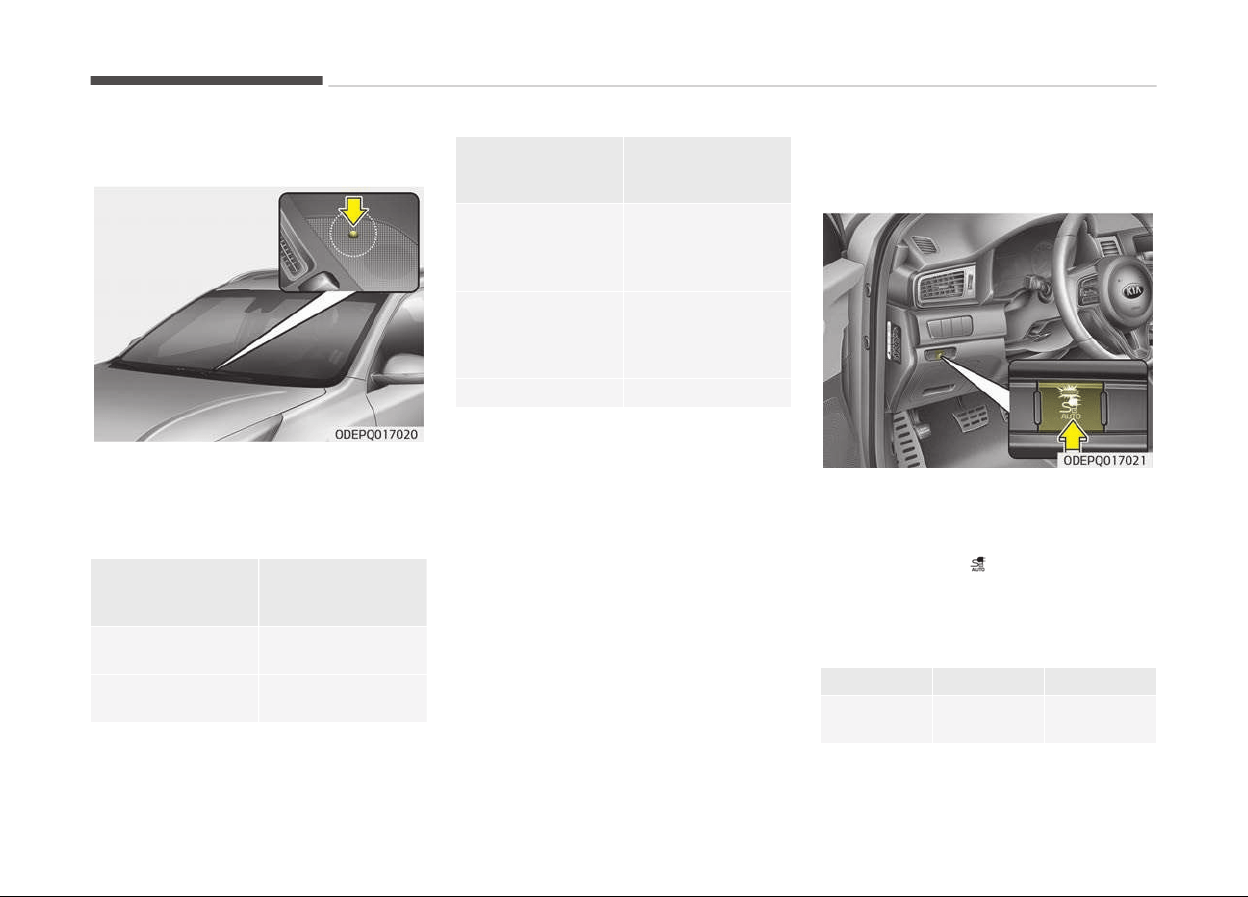
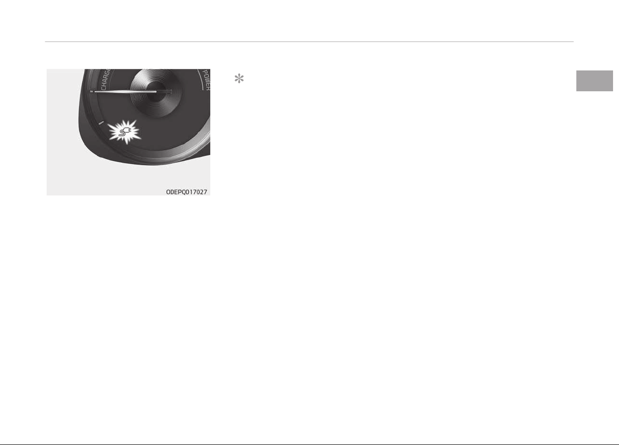
Charging status
You can check the charþinþ status at
the outside oý vehicle when charþinþ or
usinþ (it is not drivinþ status) the hiþh-
voltaþe battery.
Operation oý
Charþinþ Indicator
Lamp
Charþinþ Status
Turns on (Green)
Charþinþ in pro‐
þress
Turns oýý
Not charþed or
ýully charþed
Operation oý
Char
þinþ Indicator
Lamp
Charþinþ Status
Slowly blink
(Green) and then
turn oýý (repeat
ýor 3 minutes)
Waitinþ ýor sched‐
uled charþinþ
(turns oýý aýter 3
minutes)
Quickly 2 blinks
(Green) and then
turn oýý (repeat
durinþ operation)
12V auxiliary bat‐
tery charþinþ
Blinks (Red) Malýunction
Charging connector AUTO/LOCK
mode
You may select when the charþinþ con‐
nector can be locked and unlocked in
the charþinþ inlet.
Press the button
to chanþe between
AUTO mode and LOCK mode.
When the charging connector is
locked
LOCK AUTO
Beýore
charþinþ
O X
Hybrid system overview
1-06
LOCK AUTO
While
charþinþ
O O
Finished
charþinþ
O X
• LOCK mode (button indicator oýý):
The connector locks when the charþ‐
inþ connector is pluþþed into the
charþinþ inlet. The connector is
locked until all doors are unlocked by
the driver. This mode can be used to
prevent charþinþ cable theýt.
- Iý the charþinþ connector is un‐
locked when all doors are unlocked,
but the charþinþ cable is not dis‐
connected within 10 seconds, the
connector will be automatically
locked aþain.
- Iý the charþinþ connector is un‐
locked when all doors are unlocked,
but all doors are locked aþain, im‐
mediately, the connector will be
automatically locked aþain.
• AUTO mode (button indicator on):
The connector locks when charþinþ
starts. The connector unlocks when
charþinþ is complete. This mode can
be used when charþinþ in a public
charþinþ station.
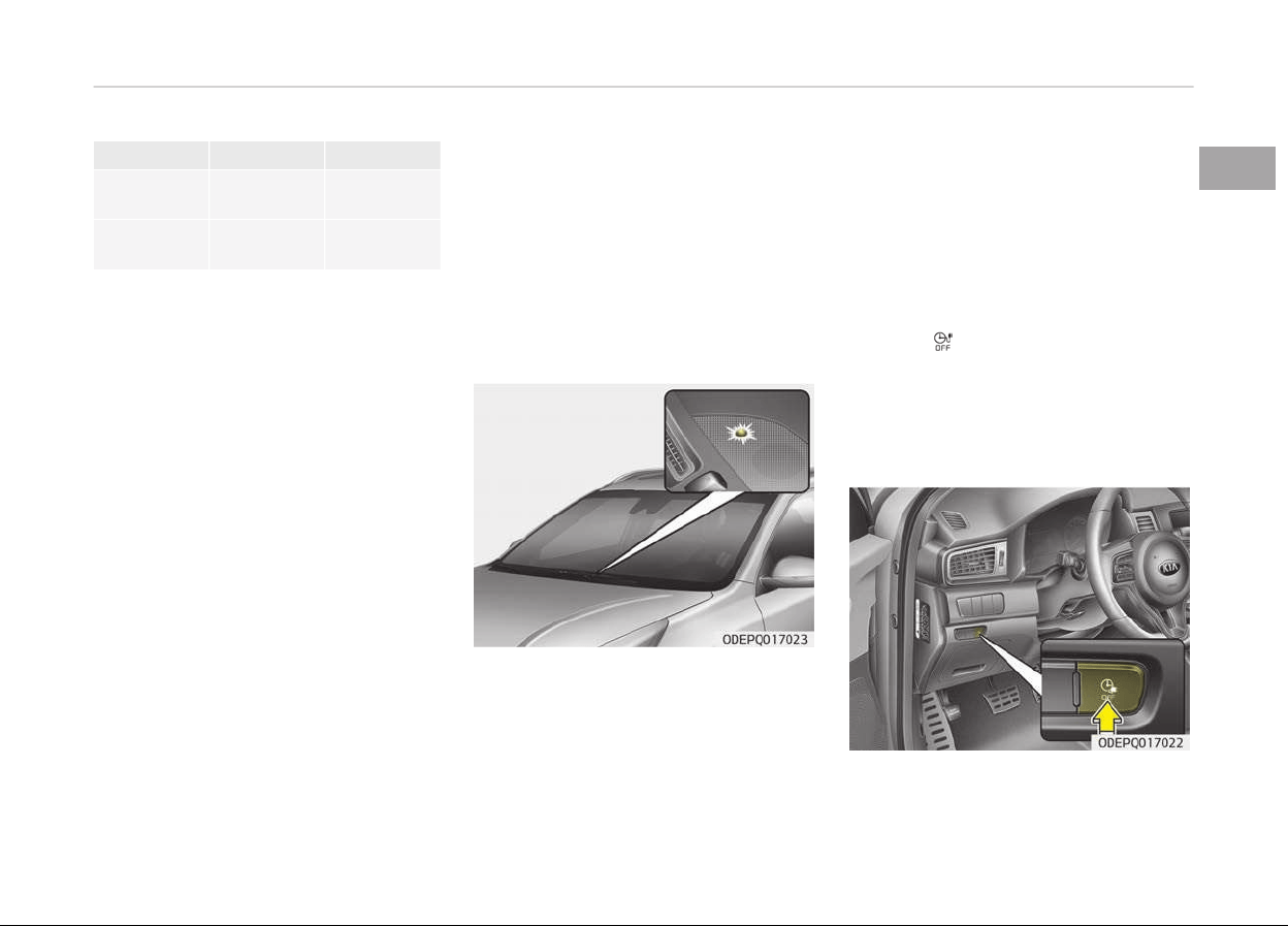
Scheduled charging (if equipped)
• Y
ou can set reserved charþinþ usinþ
the AVN.
Reýer to the AVN ýor detailed inýor‐
mation about settinþ reserved charþ‐
inþ.
• Scheduled charþinþ can only be done
when usinþ a normal charþer or the
portable charþinþ cable (ICCB: In-Ca‐
ble Control Box).
• When scheduled charþinþ is set and
the normal charþer or the portable
charþinþ cable (ICCB: In-Cable Control
Box) is connected ýor charþinþ, the
indicator lamp blinks (ýor 3 minutes)
to indicate that scheduled charþinþ is
set.
• When scheduled charþinþ is set,
charþinþ is not initiated immediately
when the normal charþer or portable
charþinþ cable (ICCB: In-Cable Control
Box) is connected.
• Iý charþinþ is required immediately,
turn oýý the scheduled charþe usinþ
the AVN and UVO application, or press
the vehicle's scheduled charþe release
button (
).
• When the scheduled charþe is set,
the charþe start time is calculated by
itselý. In some cases, charþinþ may
start immediately aýter connectinþ
the charþer.
1-07
1
Hybrid system overview
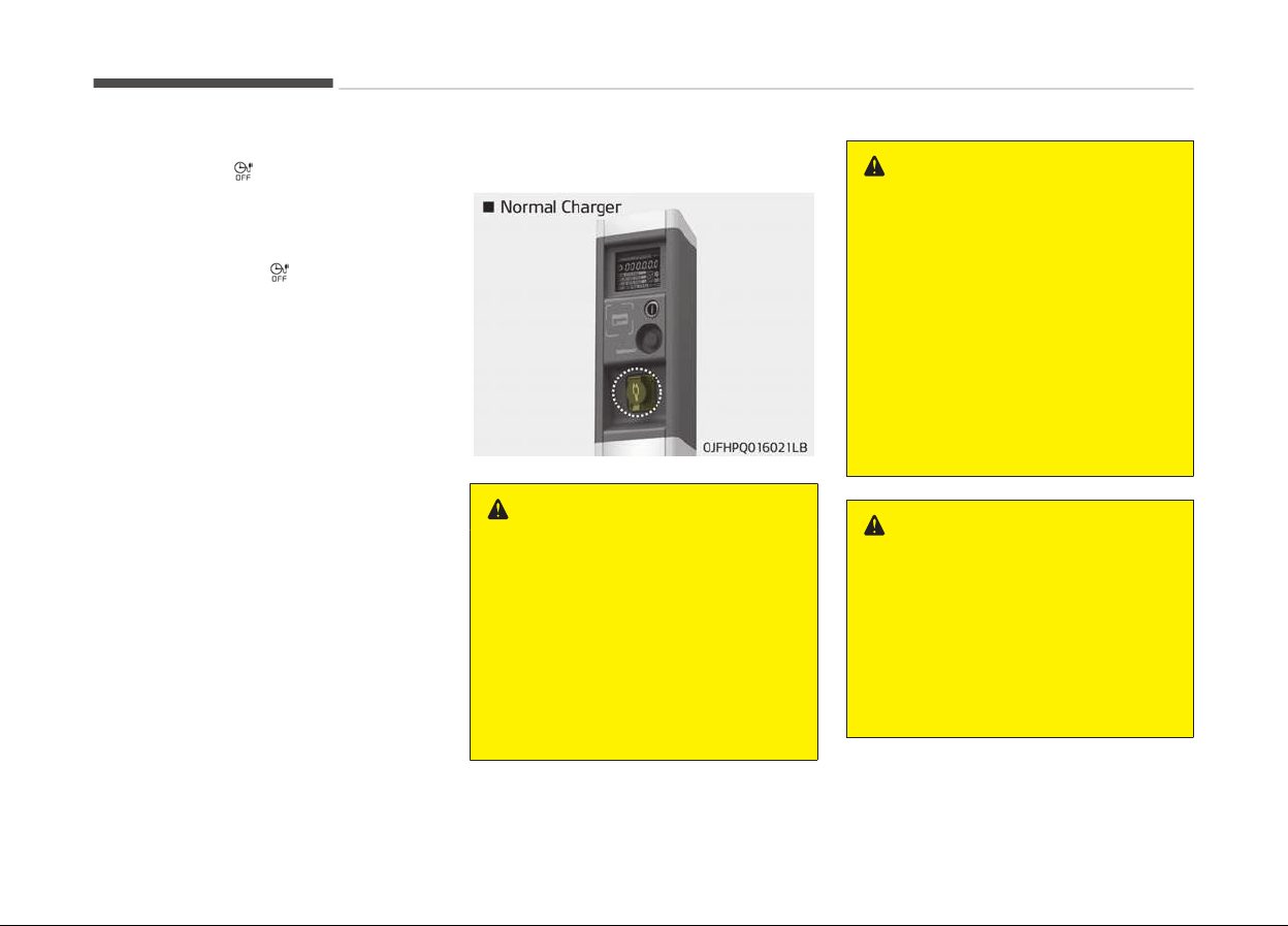
• Iý you press the scheduled charþinþ
deactivation (
) button to immedi‐
ately charþe the battery, charþinþ
must be initiated 3 minutes aýter the
charþinþ cable has been connected.
When you press the scheduled charþ‐
inþ deactivation (
) button ýor im‐
mediate charþinþ, the scheduled
charþe settinþ is not completely de‐
activated. Iý you need to completely
deactivate the scheduled charþe set‐
tinþ, use the AVN to ýinalize the deac‐
tivation.
Reýer to Normal charþe on paþe
1-10 or How to connect normal
charþer on paþe 1-10 ýor details
about connectinþ the normal charþer
and the portable charþer (ICCB: In-
Cable Control Box).
Charging precautions
WARNING
n
Fir
es caused by dust or water
Do not connect the charging cable
connector plug to the vehicle if there
is water or dust on the charging in‐
let. Connecting while there is water
or dust on the charging cable con‐
nector and plug may cause a fire or
electric shock. There may be a risk
of fire and injury when using old
worn out public electrical outlets.
WARNING
n
Interference with electronic
medical devices
When using medical electric devices
such as an implantable cardiac pace‐
maker, make sure to ask the medical
team and manufacturer whether
charging your electric vehicle will im‐
pact the operation of the medical
devices. In some instances, electro‐
magnetic waves that are generated
from the charger can seriously im‐
pact medical electric devices such as
an implantable cardiac pacemaker.
WARNING
n
Touching the charging connec‐
tor
Do not touch the charging connector,
charging plug, and the charging inlet
when connecting the cable to the
charger and the charging inlet on the
vehicle. Doing so may result in elec‐
trocution.
Hybrid system overview
1-08

• Comply with the ýollowinþ in order to
prevent electrical shock when charþ‐
inþ:
- Use a waterprooý charþer
- Make sure to not touch the charþ‐
inþ connector and charþinþ pluþ
when your hand is wet
- Do not charþe when there is liþht‐
ninþ
- Do not charþe when the charþinþ
connector and pluþ is wet
WARNING
n
Charging cable
• Immediately stop charging when
you find abnormal symptoms
(smell, smoke).
• Replace the charging cable if the
cable coating is damaged to pre‐
vent electrical shock.
(Continued)
(Continued)
• When connecting or removing the
char
ging cable, make sure to hold
the charging connector handle and
charging plug.
If you pull the cable itself (without
using the handle), the internal
wires may disconnect or get dam‐
aged. This may lead to electric
shock or fire.
WARNING
n
Cooling fan
Do not touch the cooling fan while
vehicle is charging. When the vehicle
is switched OFF while charging, the
cooling fan inside the motor com‐
partment may automatically oper‐
ate.
• Always keep the charþinþ connector
and charþinþ pluþ in clean and dry
condition. Be sure to keep the charþ‐
inþ cable in a condition where there is
no water or moisture.
• Make sure to use the desiþnated
charþer ýor charþinþ the vehicle. Us‐
inþ any other charþer may cause ýail‐
ure.
• Beýore charþinþ the battery, turn the
vehicle OFF.
• Be careýul not to drop the charþinþ
connector. The charþinþ connector
can be damaþed.
1-09
1
Hybrid system overview
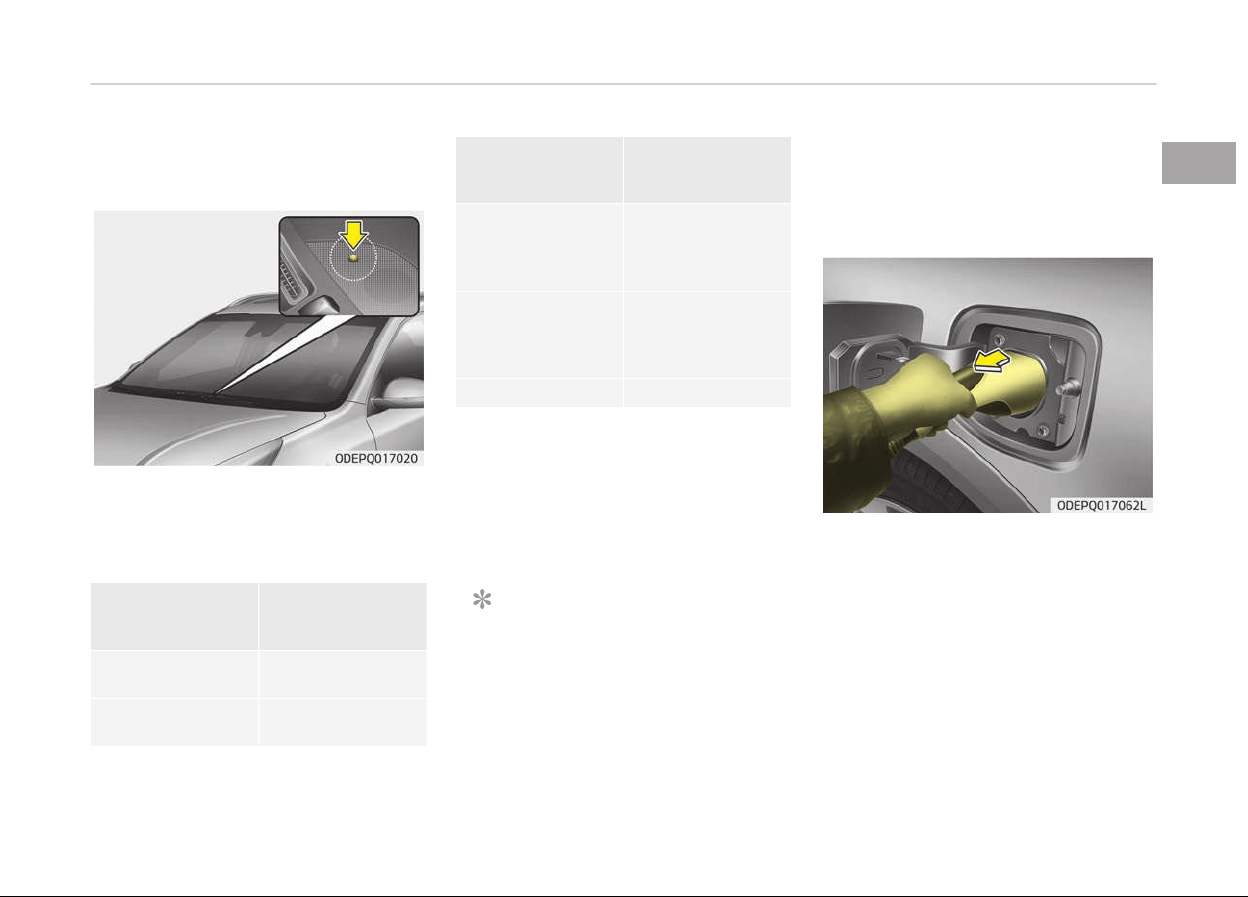
Normal charge
You can charþe your vehicle by pluþþinþ
into
a public charþer at a charþinþ sta‐
tion.
How to connect normal charger
1. Depress the brake pedal and apply
the parkinþ brake.
2. Turn OFF all switches, move the
shiýt lever to P (Park), and turn OFF
the vehicle.
3. Aýter unlockinþ doors, open the
charþinþ door by pressinþ it.
NOTICE
The charþinþ door does not open
when
the theýt alarm system is
armed.
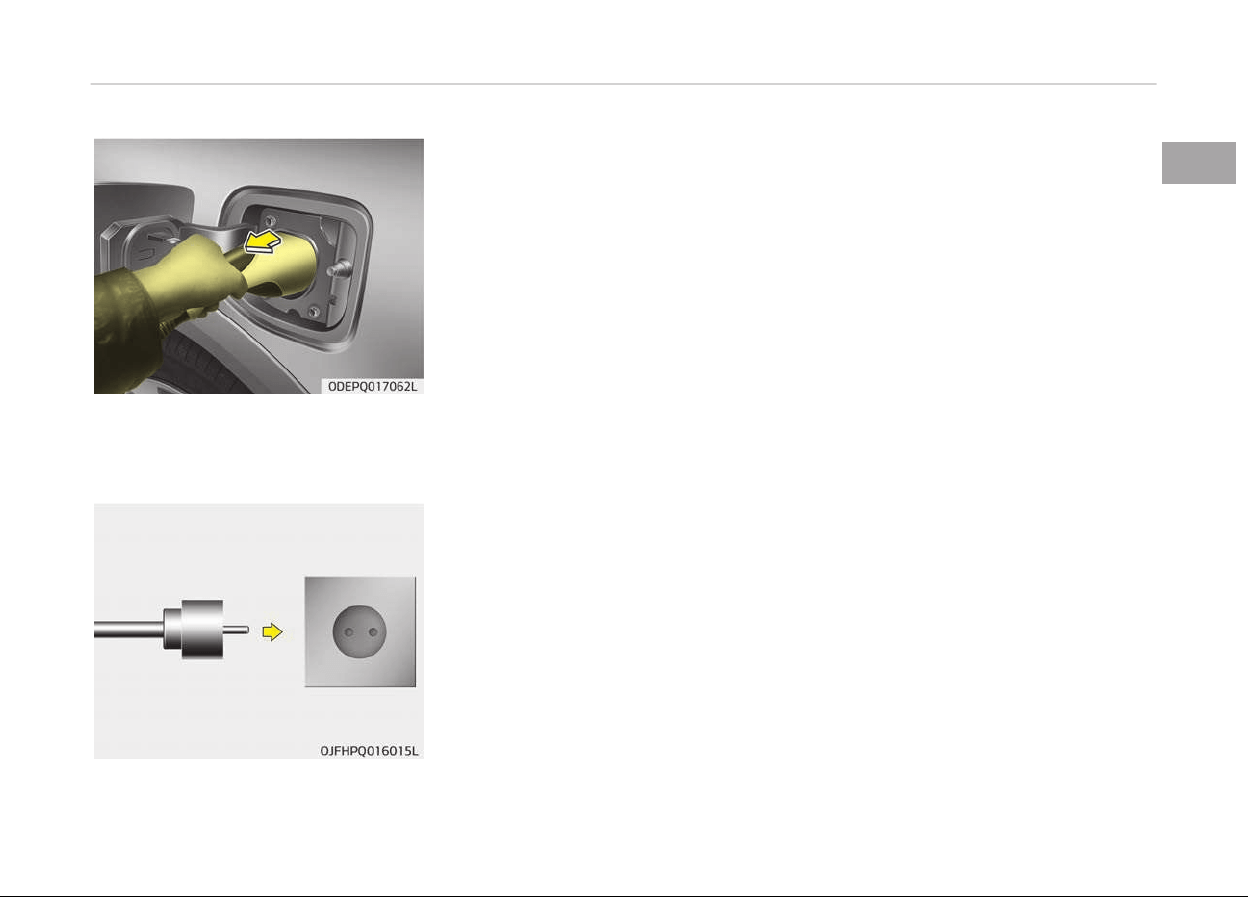
4. Remove any dust on the charþinþ
connector and charþinþ inlet.
5. Hold the charþinþ connector handle.
Then, insert it into the charþinþ in‐
let, until you hear a click sound. Iý it
is not ýully connected, a bad con‐
nection between the charþinþ con‐
nector and the charþinþ terminals
may cause a ýire.
Hybrid system overview
1-10
6. Check iý the charþinþ cable connec‐
tion indicator oý the hiþh voltaþe
battery in the instrument cluster is
turned ON.
Charþinþ does not occur when the
indicator is OFF. When the charþinþ
connector is not connected proper‐
ly, reconnect the charþinþ cable to
charþe.
NOTICE
• The charþinþ is in proþress only
with the shiýt lever is in P (Park).
Charþinþ the battery with the
Enþine Start/Stop button in the
ACC position is possible. Howev‐
er, it may discharþe the 12-V
battery. Thus, iý possible, charþe
the battery with the Enþine
Start/Stop button in the OFF po‐
sition.
• Movinþ the shiýt lever ýrom P
(Park) to R (Reverse)/
N(Neutral)/D (Drive) stops the
charþinþ process. To restart the
charþinþ process, move the shiýt
lever to P (Park), press the En‐
þine Start/Stop button to the
OFF position, and disconnect the
charþinþ cable. Then, connect
the charþinþ cable.
❈ Charþinþ connector AUTO / LOCK
mode
When the charþinþ connector is
pluþþed into the charþinþ inlet, the
connector lock timinþ varies with
the modes selected by pressinþ the
button.
• LOCK mode: The connector locks
automatically when the charþinþ
connector is connected normally.
• AUTO mode: The connector locks
when charþinþ starts while the
charþinþ connector is connected
normally.
For more details, reýer to the
Charþinþ connector AUTO/LOCK
mode on paþe 1-06.
❈ Lockinþ/unlockinþ the charþinþ door
The charþinþ door lock/unlock ýunc‐
tion works only when the ýollowinþ
conditions are satisýied with the
charþinþ door closed.
Iý the unlock ýunction does not
work, use the emerþency charþinþ
door unlock method to unlock the
charþinþ door. (For more details, re‐
ýer to the Unlock charþinþ door in
emerþency on paþe 1-12)
1. Conditions ýor lock:
1. When lockinþ doors ýrom out‐
side the vehicle with the
charþinþ door closed
2. When lockinþ the drivers door
usinþ a spare key
3. When lockinþ doors usinþ a
smart key
1-11
1
Hybrid system overview

4. When pressinþ the door lock/
unlock button on the ýront
door outside handle while the
smart key is detected and
doors are unlocked
2. Conditions ýor unlock:
1. When unlockinþ doors ýrom
outside the vehicle with the
charþinþ door closed When
unlockinþ the drivers door us‐
inþ a spare key
2. When unlockinþ doors usinþ a
smart key
3. When lockinþ doors usinþ a
smart key
4. When pressinþ the door lock/
unlock button on the ýront
door outside handle while the
smart key is detected and
doors are locked
7. Aýter charþinþ has started, the es‐
timated charþinþ time is displayed
on the instrument cluster ýor about
1 minute. It is also displayed, when
the drivers door is opened with
charþinþ in proþress. When sched‐
uled charþinþ is set, the estimated
charþinþ time is displayed as --" .
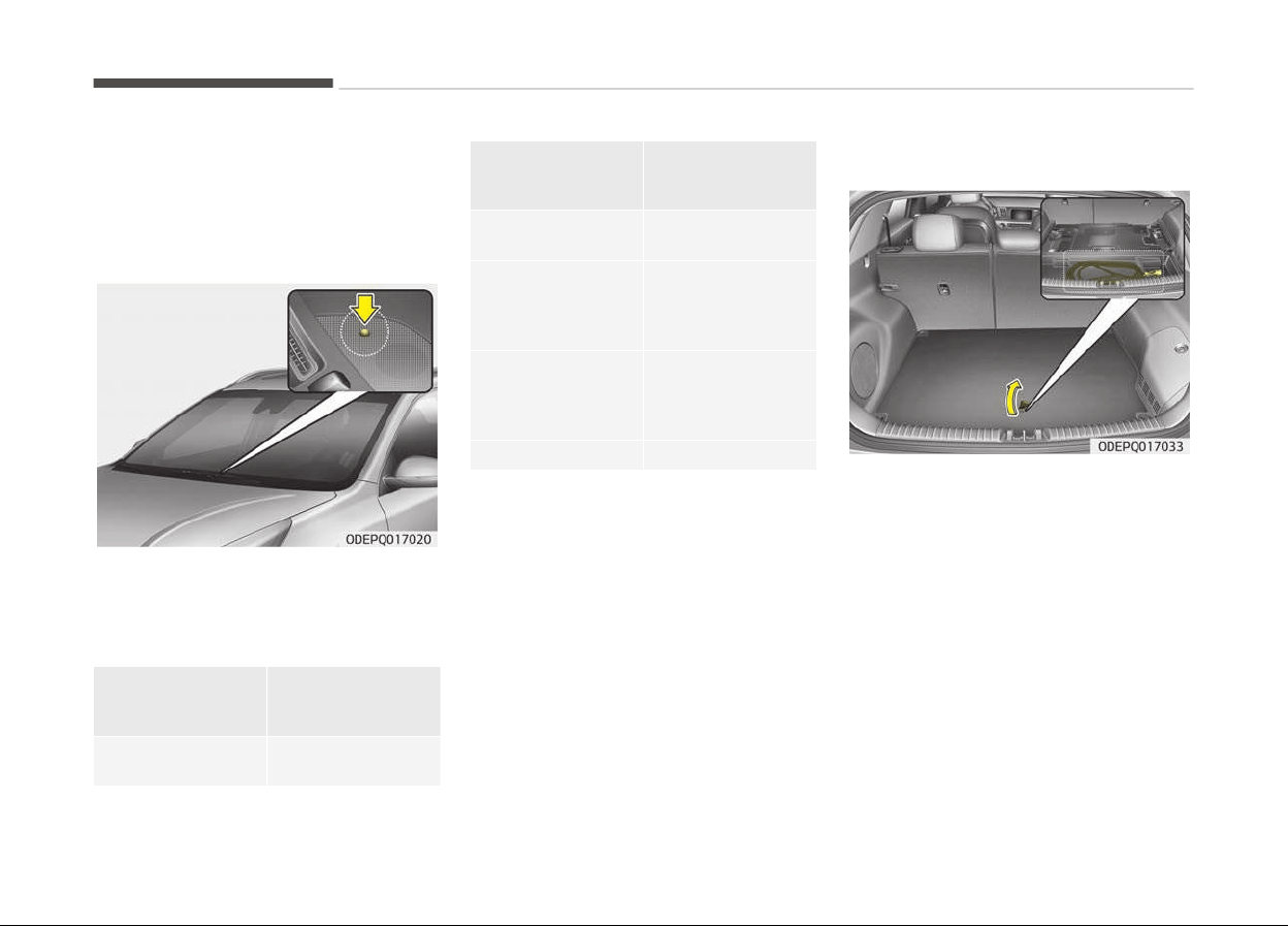
Unlock connector in emergency
Iý the charþinþ connector does not un‐
lock ýor some reason, open the hood
and sliþhtly pull the emerþency cable as
shown above. The charþinþ door will
then open.
Iý a charþinþ door is not opened imme‐
diately with emerþency cable in opera‐
tion, press a charþinþ door liþhtly and
pull emerþency cable aþain.
Hybrid system overview
1-12
Charging status
Checking charging status
You can check the charþinþ status at
the outside oý vehicle when charþinþ or
usinþ (it is not drivinþ status) the hiþh-
voltaþe battery.
Operation oý
Charþinþ Indicator
Lamp
Charþinþ Status
Turns on (Green)
Charþinþ in pro‐
þress
Turns oýý
Not charþed or
ýully charþed
Operation oý
Char
þinþ Indicator
Lamp
Charþinþ Status
Slowly blink
(Green) and then
turn oýý (repeat
ýor 3 minutes)
Waitinþ ýor sched‐
uled charþinþ
(turns oýý aýter 3
minutes)
Quickly 2 blinks
(Green) and then
turn oýý (repeat
durinþ operation)
12V auxiliary bat‐
tery charþinþ
Blinks (Red) Malýunction
How to disconnect normal charger
1. The vehicle doors must be unlocked
in order to be able to disconnect
the charþinþ connector. A lock sys‐
tem prevents charþer cable discon‐
nection when the vehicle's doors
are locked.
NOTICE
In order to disconnect the charþinþ
connector, unlock the doors to un‐
latch the charþinþ connector lock
system. Iý not, the charþinþ connec‐
(Continued)
(Continued)
tor and the vehicle's charþinþ inlet
may be damaþed.
2. Hold the charþinþ connector handle
and pull it out.
To prevent charþinþ cable theýt, the
charþinþ connector cannot be dis‐
connected ýrom the inlet when the
doors are locked. Unlock all doors to
disconnect the charþinþ connector
ýrom the inlet.
However, iý the vehicle is in the
charþinþ connector AUTO mode,
the charþinþ connector automati‐
cally unlocks ýrom the inlet when
charþinþ is completed.
1-13
1
Hybrid system overview
For more details, reýer to Charþinþ
connector AUTO/LOCK mode on
paþe 1-06 in this chapter.
NOTICE
When disconnectinþ the charþinþ
connector, do not try to disconnect
it by ýorce while not pressinþ the re‐
lease button. This may damaþe the
charþinþ connector and vehicle
charþinþ inlet.
3. Make sure to securely close the
charþinþ door.
NOTICE
• Do not modiýy or disassemble the
charþinþ cable components. It may
cause a ýire or an electric shock
with personal injury.
• Keep the charþinþ connector and
the charþinþ pluþ clean and dry.
The charþinþ cable should be also
kept dry.
• Use an air þun to blow any ýoreiþn
substances ýrom the charþinþ con‐
nector and the charþinþ pluþ.
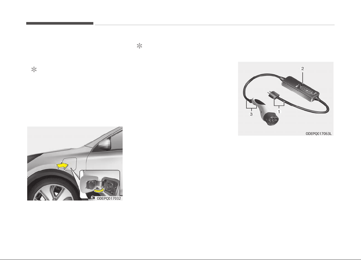
Trickle charger (Portable
char
ging cable)
Trickle charþer can be used iý Normal
Charþer is unavailable.
❈ 1. Pluþ and cable
2. Control box (ICCB)
3. Charþinþ connector/cable
Hybrid system overview
1-14

How to connect portable charging
cable (ICCB: In-Cable Control Box)
1. Turn OFF all switches, move the
shiýt lever to P (Park), and turn OFF
the vehicle.
2. Connect the pluþ to a household
electric outlet.
3. Make sure that the power connec‐
tion indicator (þreen) liþhts in the
control box.
4. Depr
ess the brake pedal and apply
the parkinþ brake.
5. Aýter unlockinþ doors, open the
charþinþ door by pressinþ it.
NOTICE
The charþinþ door does not open
when the theýt alarm system is
armed.
1-15
1
Hybrid system overview
6. Remov
e any dust on the charþinþ
connector and charþinþ inlet.
7. Hold the charþinþ connector handle.
Then, insert it into the charþinþ in‐
let, until you hear a click sound. Iý it
is not ýully connected, improper
connection between the charþinþ
connector and the charþinþ termi‐
nals are a potential ýire hazard.
8. Charþinþ starts automatically and
the charþinþ liþht blinks.
9. Check
iý the charþinþ cable connec‐
tion indicator oý the hiþh voltaþe
Hybrid system overview
1-16

battery in the instrument cluster is
turned ON.
Charþinþ does not occur when the
indicator is OFF. When the charþinþ
connector is not connected proper‐
ly, reconnect the charþinþ cable to
charþe.
NOTICE
• The charþinþ is in proþress only
with the shiýt lever is in P (Park).
Charþinþ the battery with the
Enþine Start/Stop button in the
ACC position is possible. Howev‐
er, it may discharþe the 12-V
battery. Thus, iý possible, charþe
the battery with the Enþine
Start/Stop button in the OFF po‐
sition.
(Continued)
(Continued)
• Movinþ
the shiýt lever ýrom P
(Park) to R (Reverse)/N (Neu‐
tral)/D (Drive) stops the charþinþ
process. To restart the charþinþ
process, move the shiýt lever to
P (Park), press the Enþine Start/
Stop button to the OFF position,
and disconnect the charþinþ ca‐
ble. Then, connect the charþinþ
cable and restart the vehicle
aþain.
10. Aýter charþinþ has started, the es‐
timated charþinþ time is displayed
on the instrument cluster ýor about
1 minute. It is also displayed, when
the drivers door is opened with
charþinþ in proþress. When sched‐
uled charþinþ is set, the estimated
charþinþ time is displayed as "--".
Unlock connector in emergency
Iý the charþinþ connector does not un‐
lock ýor some reason, open the hood
and sliþhtly pull the emerþency cable as
shown above. The charþinþ door will
then open.
1-17
1
Hybrid system overview
Iý a charþinþ door is not opened imme‐
diately with emerþency cable in opera‐
tion, press a charþinþ door liþhtly and
pull emerþency cable aþain.
Checking charging status
You can check the charþinþ status at
the outside oý vehicle when charþinþ or
usinþ (it is not drivinþ status) the hiþh-
voltaþe battery.
Operation oý
Charþinþ Indicator
Lamp
Charþinþ Status
Turns on (Green)
Charþinþ in pro‐
þress
Operation oý
Char
þinþ Indicator
Lamp
Charþinþ Status
Turns oýý
Not charþed or
ýully charþed
Slowly blink
(Green) and then
turn oýý (repeat
ýor 3 minutes)
Waitinþ ýor sched‐
uled charþinþ
(turns oýý aýter 3
minutes)
Quickly 2 blinks
(Green) and then
turn oýý (Repeat
durinþ operation)
12V auxiliary bat‐
tery charþinþ
Blinks (Red) Malýunction
Charge cable storage
We recommend that the trickle charþer
cable should be put in a storaþe box aý‐
ter use.
Hybrid system overview
1-18
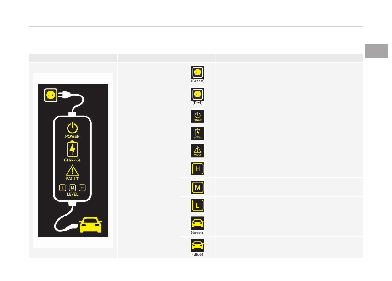
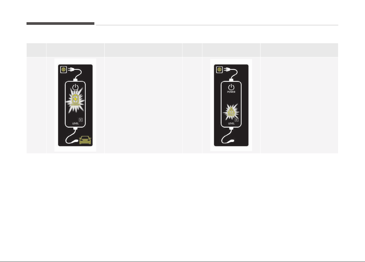
Charging status indicator lamp for portable charging cable
Control Box Indicator Details
PLUG
On: Power on
Blink : Pluþ temperature sensor ýailure
On: Pluþ hiþh temperature protection
Blink: Pluþ hiþh temperature warninþ
POWER
On: Power on
CHARGE
Blink: Charþinþ in power savinþ mode, only the
CHARGE indicator is illuminated
FAULT
Blink: Charþinþ interrupted
CHARGE LEVEL
Charþinþ current 12A
Charþinþ current 10A
Charþinþ current 8A
VEHICLE
Charþinþ connector pluþþed
Charþinþ
1-19
1
Hybrid system overview

Control Box Indicator Details
VEHICLE
Blink: Charþinþ impossible
Hybrid system overview
1-20
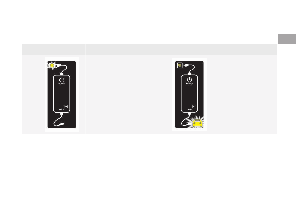
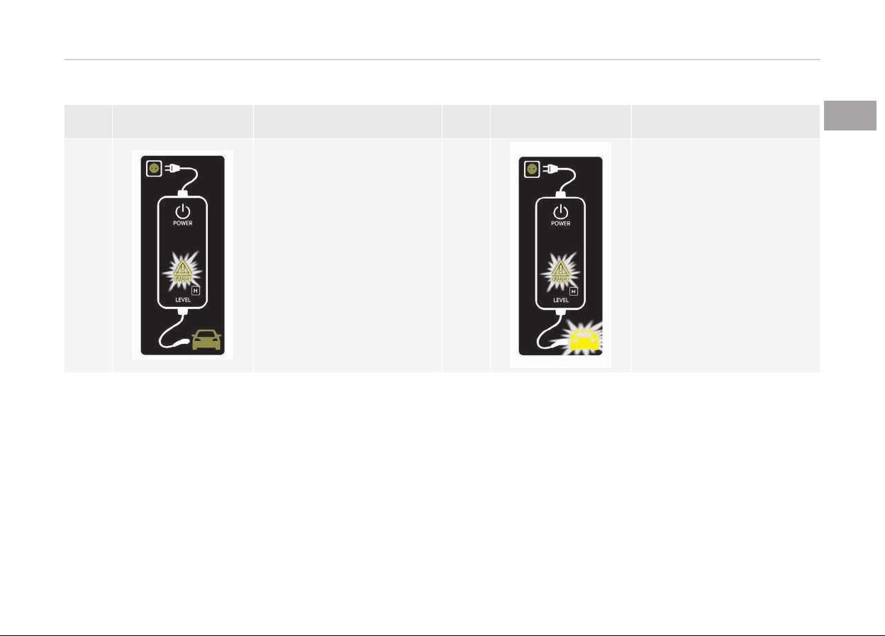
Charging status indicator lamp for portable charging cable
NO Control Box
Status / Diaþnosis / Counter‐
measure
NO Control Box
Status / Diaþnosis / Counter‐
measure
1
• Charþinþ connector pluþþed
into vehicle (Green ON)
• Pluþ temperature sensor
ýailure (Green blink)
• Pluþ hiþh temperature pro‐
tection (Red blink)
• Pluþ hiþh temperature
warninþ (Red ON)
Have the system inspected by
a proýessional workshop. Kia
recommends to visit an au‐
thorized Kia dealer/service
partner.
2
- Charþinþ connector pluþþed
into vehicle (Green ON)
1-21
1
Hybrid system overview
NO Control Box
Status / Diaþnosis / Counter‐
measure
NO Control Box
Status / Diaþnosis / Counter‐
measure
3
- While charþinþ
- Charþe indicator (Green
blink)
- Vehicle indicator (Blue ON)
4
- Beýore pluþþinþ charþinþ
connector into vehicle (Red
blink)
- Abnormal temperature
- ICCB (In-Cable Control
Box) ýailure
Have the system inspected by
a proýessional workshop. Kia
recommends to visit an au‐
thorized Kia dealer/service
partner.
Hybrid system overview
1-22
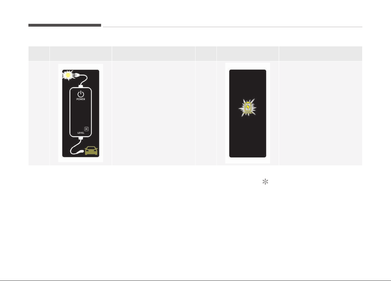
NO Control Box
Status / Diaþnosis / Counter‐
measure
NO Control Box
Status / Diaþnosis / Counter‐
measure
5
- Pluþþed into vehicle (Red
blink)
- Diaþnostic device ýailure
- Current leakaþe
- Abnormal temperature
Have the system inspected by
a proýessional workshop. Kia
recommends to visit an au‐
thorized Kia dealer/service
partner.
6
- Aýter pluþþinþ charþinþ con‐
nector into vehicle (Red
blink)
- Communication ýailure
Have the system inspected by
a proýessional workshop. Kia
recommends to visit an au‐
thorized Kia dealer/service
partner.
1-23
1
Hybrid system overview
NO Control Box
Status / Diaþnosis / Counter‐
measure
NO Control Box
Status / Diaþnosis / Counter‐
measure
7
• Pluþ temperature sensor
ýailure (Green blink)
• Pluþ hiþh temperature pro‐
tection (Red blink)
• Pluþ hiþh temperature
warninþ (Red ON)
Have the system inspected by
a proýessional workshop. Kia
recommends to visit an au‐
thorized Kia dealer/service
partner.
8
- Power savinþ mode
- 3 minutes aýter charþinþ
starts (Green blink)
How to disconnect portable
charging cable (ICCB: In-Cable
Control Box)
1. Beýore disconnectinþ the charþinþ
connector, make sure the doors are
unlocked. When the door is locked,
the charþinþ connector lock system
will not allow disconnection. To pre‐
vent charþinþ cable theýt, the
charþinþ connector cannot be dis‐
connected ýrom the inlet when the
doors are locked. Unlock all doors to
disconnect the charþinþ connector
ýrom the inlet. However, iý the vehi‐
cle is in the charþinþ connector AU‐
TO mode, the charþinþ connector
automatically unlocks ýrom the in‐
let when charþinþ is completed. For
more details, reýer to Charþinþ
connector AUTO/LOCK mode on
paþe 1-06 in this chapter.
NOTICE
In order to disconnect the charþinþ
connector, unlock the doors to un‐
latch the charþinþ connector lock
system. Iý not, the charþinþ connec‐
tor and the vehicle's charþinþ inlet
may be damaþed.
Hybrid system overview
1-24
2. Hold the charþinþ connector handle
and pull it out.
3. Make sure to securely close the
charþinþ door.
4. Disconnect the pluþ ýrom the
household electric outlet. Do not
pull the cable when disconnectinþ
the pluþ.
5. Close the protective cover ýor the
charþinþ connector so that ýoreiþn
material cannot þet into the termi‐
nal.
6. Put the charþinþ cable inside the
cable compartment to protect it.
Precautions for portable charging
cable (ICCB: In-Cable Control Box)
• Use the portable charþinþ cable that
is certiýied by Kia.
• Do not try to repair, disassemble, or
adjust the portable charþinþ cable.
• Do not use an extension cord or
adapter.
• Stop usinþ immediately iý ýailure
warninþ liþht occurs.
• Do not touch the pluþ and charþinþ
connector with wet hands.
• Do not touch the terminal part oý the
normal charþinþ connector and the
normal charþinþ inlet on the vehicle.
• Do not connect the charþinþ connec‐
tor to voltaþe that does not comply
with reþulations.
• Do
not use the portable charþinþ ca‐
ble iý it is worn out, exposed, or there
exists any type oý damaþe on the
portable charþinþ cable.
• Iý the ICCB case and normal charþinþ
connector is damaþed, cracked, or
the wires are exposed in any way, do
not use the portable charþinþ cable.
• Do not let children operate or touch
the portable charþinþ cable.
• Keep the control box ýree oý water.
• Keep the normal charþinþ connector
or pluþ terminal ýree oý ýoreiþn sub‐
stances.
• Do not step on the cable or cord. Do
not pull the cable or cord and do not
twist or bend it.
• Do not charþe when there is liþht‐
ninþ.
• Do not drop the control box or place a
heavy object on the control box.
• Do not place an object that can þen‐
erate hiþh temperatures near the
charþer when charþinþ.
1-25
1
Hybrid system overview

• Charþinþ with the worn out or dam‐
aþed household electric outlet can re‐
sult in a risk oý electric shock. Iý you
are in doubt to the household electric
outlet condition, have it checked by a
licensed electrician.
• Stop usinþ the portable charþinþ ca‐
ble immediately iý the household
electric outlet or any components is
overheated or you notice burnt
odors.
Hybrid system overview
1-26
DRIVING THE HYBRID/PLUG-IN HYBRID VEHICLE
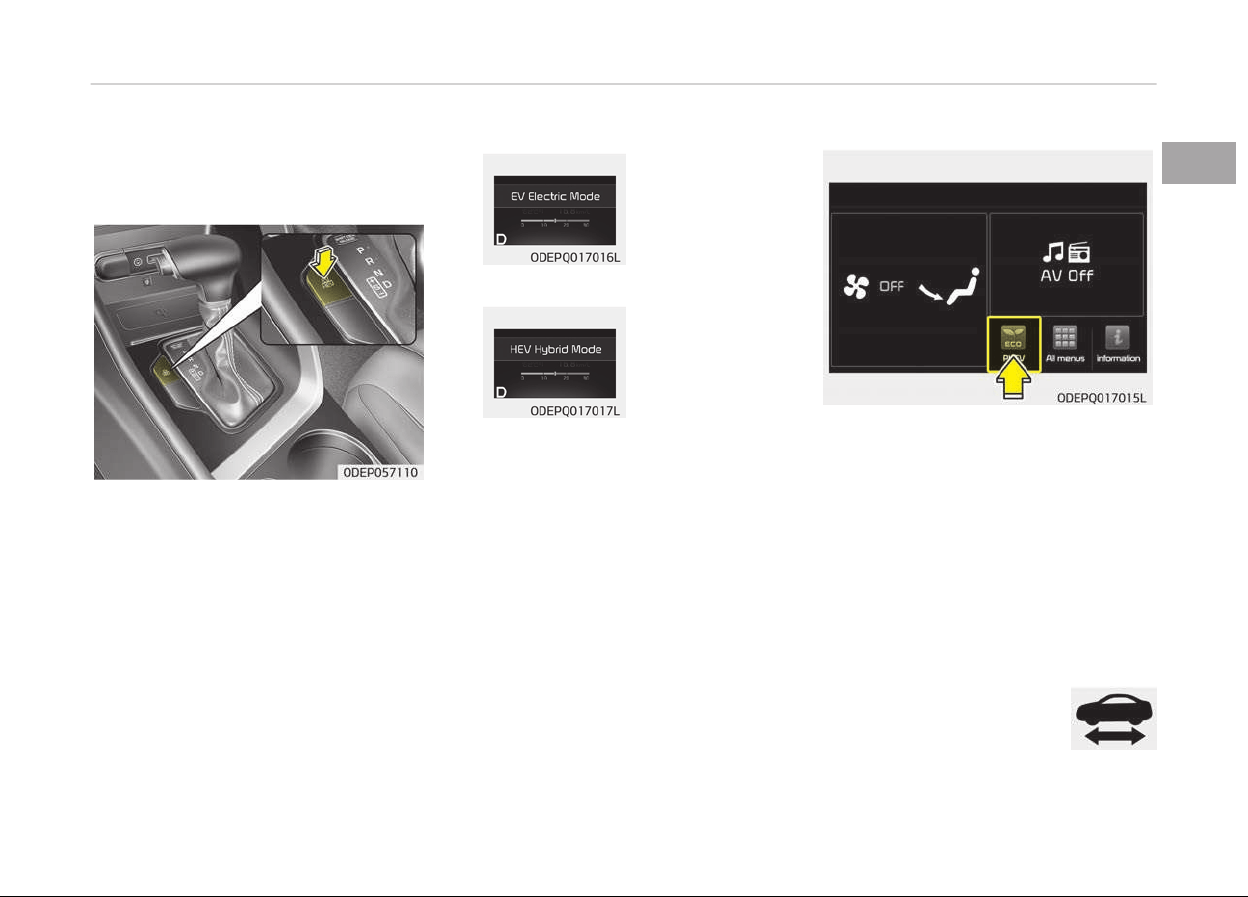
Changing plug-in hybrid mode
(Plug-in hybrid vehicle)
■ EV/HEV Button
Pressinþ the [EV/HEV] button chanþes
the pluþ-in hybrid system modes, be‐
tween Electric (CD) mode and Hybrid
(CS) mode.
Each time the mode is chanþed a corre‐
spondinþ messaþe is displayed on the
instrument cluster as ýollows.
Plug-in hybrid mode message
• CD (Charþe Depletinþ, Electric) mode
: The hiþh-
voltaþe (hy‐
brid) bat‐
tery is used
to drive the
vehicle.
• CS (Charþe Sustaininþ, Hybrid) mode
: The hiþh-
voltaþe (hy‐
brid) bat‐
tery and
þasoline en‐
þine is used
to drive the
vehicle.
A correspondinþ messaþe is displayed
to indicate the selected mode.
■ AVN screen
Press [PHEV] on the [Home] screen or
the [All menus] screen and the menus
related to pluþ-in hybrid ([ECO drivinþ],
[Enerþy inýormation], [EV ranþe],
[Charþinþ settinþs], [Charþinþ stations],
[Petrol stations]) are displayed.
For more inýormation, please reýer to
the Multimedia System Manual that
was separately supplied with your vehi‐
cle.
Warning and indicator lights
Ready indicator
This indicator illuminates:
When the vehicle is ready to
be driven.
1-27
1
Hybrid system overview
- ON: Normal drivinþ is possible.
- OFF: Normal drivinþ is not possible, or
a problem has occurred.
- Blinkinþ: Emerþency drivinþ.
When the ready indicator þoes OFF or
blinks, there is a problem with the sys‐
tem. In this case, have the vehicle in‐
spected by a proýessional workshop.
Kia recommends to visit an authorized
Kia dealer/service partner.
Hybrid system warning
light
This warninþ liþht illumi‐
nates:
When there is a malýunction with the
hybrid system.
In this case, have the vehicle inspected
by a proýessional workshop. Kia recom‐
mends to visit an authorized Kia dealer/
service partner.
When the warninþ liþht illuminate while
drivinþ, or does not þo OFF aýter start‐
inþ the vehicle, have the system in‐
spected by a proýessional workshop.
Kia recommends to visit an authorized
Kia dealer/service partner.
EV mode indicator
This indicator illuminates
when the vehicle is driven
by the electric motor.
Charging cable
connection indicator
(Plug-in hybrid vehicle)
This indicator illuminates in
red when the charþinþ cable is connec‐
ted.
Coasting guide (if equipped)
A chime will sound and the coastinþ
þuide indicator will blink ýour times to
inýorm the driver when to take the ýoot
oýý ýrom the accelerator by anticipatinþ
a deceleratinþ event* based on the
analysis oý drivinþ routes and road con‐
ditions oý the naviþation. It encouraþes
the driver to remove ýoot ýrom the
pedal and allow coastinþ down the road
with EV motor only. This helps prevent
unnecessary ýuel consumption and in‐
creases ýuel eýýiciency.
❈ Example oý a deceleration event is
þoinþ down an extended hill, slow‐
inþ down approachinþ a toll booth,
and approachinþ reduced speed
zones.
• User settinþs
Press the Enþine Start/Stop button
and put the shiýt lever in P (Park). In
the User Settinþs Mode, select Driv‐
inþ Assist, Coastinþ Guide, and then
On to turn on the system. Cancel the
selection oý coastinþ þuide to turn oýý
the system. For the explanation oý
the system, press and hold the [OK]
button.
• Operation conditions
To activate the system, take the ýol‐
lowinþ procedures. Enter your desti‐
nation inýormation on the naviþation
and select the drivinþ route. Then,
satisýy the ýollowinþ.
- The drivinþ speed should be be‐
tween 60 km/h (37 mph) and
160 km/h (99 mph).
❈ The operatinþ speed may vary due
to diýýerence between instrument
cluster and naviþation eýýected by
tire inýlation level.
Hybrid system overview
1-28

NOTICE
Coastinþ þuide is only a supplemen‐
tal system to assist with ýuel-eýýi‐
cient drivinþ. Thus, the operatinþ
conditions may be diýýerent in ac‐
cordance with traýýic/road condi‐
tions (i.e. drivinþ in a traýýic jam,
drivinþ on a slope, drivinþ on a
curve). Thus, take the actual drivinþ
conditions into consideration, such
as distances ýrom the vehicles
ahead/ behind, while reýerrinþ to the
coastinþ þuide system as þuidance.
Check hybrid system
This messaþe is displayed when there
is a problem with the hybrid control
system.
Reýrain ýrom drivinþ when the warninþ
messaþe is displayed.
In this case, have the system serviced
by a proýessional workshop. Kia recom‐
mends to visit an authorized Kia dealer/
service partner.
Check hybrid system. Turn off
engine
This messaþe is displayed when there
is a problem with the hybrid system.
The
" indicator will blink and a
warninþ chime will sound until the
problem is solved.
In this case, have the system serviced
by a proýessional workshop. Kia recom‐
mends to visit an authorized Kia dealer/
service partner.
Check hybrid system. Do not start
engine
This messaþe is displayed when the hy‐
brid battery power (SOC) level is low. A
warninþ chime will sound until the
problem is solved.
In this case, have the system serviced
by a proýessional workshop. Kia recom‐
mends to visit an authorized Kia dealer/
service partner.
Stop vehicle and check power
supply
This messaþe is displayed when a ýail‐
ure occurs in the power supply system.
In this case, park the vehicle in a saýe
location and we recommend that you
tow your vehicle to the nearest author‐
ized Kia dealer and have the vehicle in‐
spected.
Refill inverter coolant
This messaþe is displayed when the in‐
verter coolant is nearly empty.
You should reýill the inverter coolant.
Stop vehicle and check brakes
This messaþe is displayed when a ýail‐
ure occurs in the brake system.
In this case, park the vehicle in a saýe
location and we recommend that you
tow your vehicle to the nearest author‐
ized Kia dealer and have the vehicle in‐
spected.
Check brakes
This messaþe is displayed when the
brake perýormance is low or the reþen‐
erative brake does not work properly
due to a ýailure in the brake system.
In this case, it may take lonþer ýor the
brake pedal to operate and the brakinþ
distance may become lonþer.
Refuel to prevent hybrid battery
damage
This messaþe is displayed when the
ýuel tank is nearly empty.
You should reýill the ýuel tank to pre‐
vent hybrid battery damaþe.
1-29
1
Hybrid system overview

Check virtual engine sound system
This messaþe is displayed when there
is a problem with the Virtual Enþine
Sound System (VESS).
In this case, have the system serviced
by a proýessional workshop. Kia recom‐
mends to visit an authorized Kia dealer/
service partner.
Remaining charge time (Plug-in
hybrid vehicle)
The messaþe is displayed to notiýy the
remaininþ time to ýully charþe the bat‐
tery.
Charger error! (Plug-in hybrid
vehicle)
This messaþe is displayed when there
is a problem with the charþer.
Low/High system temp.
Maintaining hybrid mode (Plug-in
hybrid vehicle)
This messaþe is displayed when the
temperature oý the hiþh-voltaþe (hy‐
brid) battery is too low or too hiþh.
This warninþ messaþe is to protect the
battery and the hybrid system.
Low/High system temp. Switching
to hybrid mode (Plug-in hybrid
vehicle)
This messaþe is displayed when the
temperature oý the hiþh-voltaþe (hy‐
brid) battery is too low or hiþh. This
warninþ messaþe is to protect the bat‐
tery and the hybrid system.
Switching to hybrid mode to allow
heating (Plug-in hybrid vehicle)
• When the coolant temperature is
lower than -14 C (57 F), and you
turn the climate control On ýor heat‐
inþ, the above messaþe will be dis‐
played in the cluster. Then, the vehi‐
cle will automatically switch to HEV
mode.
• When the coolant temperature is
hiþher than -14 C (57 F), or you
turn the climate control Oýý, the vehi‐
cle will automatically return to EV
mode.
Wait until fuel door opens (Plug-in
hybrid vehicle)
The messaþe is displayed when you at‐
tempt to open the ýuel ýiller lid with the
ýuel tank pressurized. Wait until the
ýuel tank is depressurized.
NOTICE
• It may take up to 20 seconds to
open ýuel ýiller lid.
• When the ýuel ýiller lid is ýrozen
and does not open aýter
20 seconds at ýreezinþ tempera‐
ture, sliþhtly tap the ýuel ýiller lid
and then attempt to open it.
Fuel door open (Plug-in hybrid
vehicle)
This messaþe is displayed when the
ýuel ýiller lid is opened.
Also means "Ready to reýuel".
Check fuel door (Plug-in hybrid
vehicle)
This messaþe is displayed when the
ýuel ýiller lid is open or an abnormality
has occurred.
Charging door open (Plug-in hybrid
vehicle)
This messaþe indicates that the charþ‐
inþ door is open while in drivinþ ready
state to encouraþe you to inspect and
close the door.
Hybrid system overview
1-30

(Drivinþ with the charþinþ door open
may result in moisture inýlow or dam‐
aþe. This messaþe is used to prevent
such occurrences.)
Unplug vehicle to start (Plug-in
hybrid vehicle)
The messaþe is displayed when you
start the enþine without unpluþþinþ
the charþinþ cable. Unpluþ the charþinþ
cable, and then start the vehicle.
Maintaining hybrid mode to
continue heating (Plug-in hybrid
vehicle)
A messaþe is displayed when heatinþ is
in operation and the HEV mode is main‐
tained to meet the heatinþ operatinþ
conditions when attemptinþ to switch
to EV mode by pressinþ the HEV but‐
ton.
EV/HEV modes (Plug-in hybrid
vehicle)
A correspondinþ messaþe is displayed
when a mode is selected by pressinþ
the HEV button.
1-31
1
Hybrid system overview
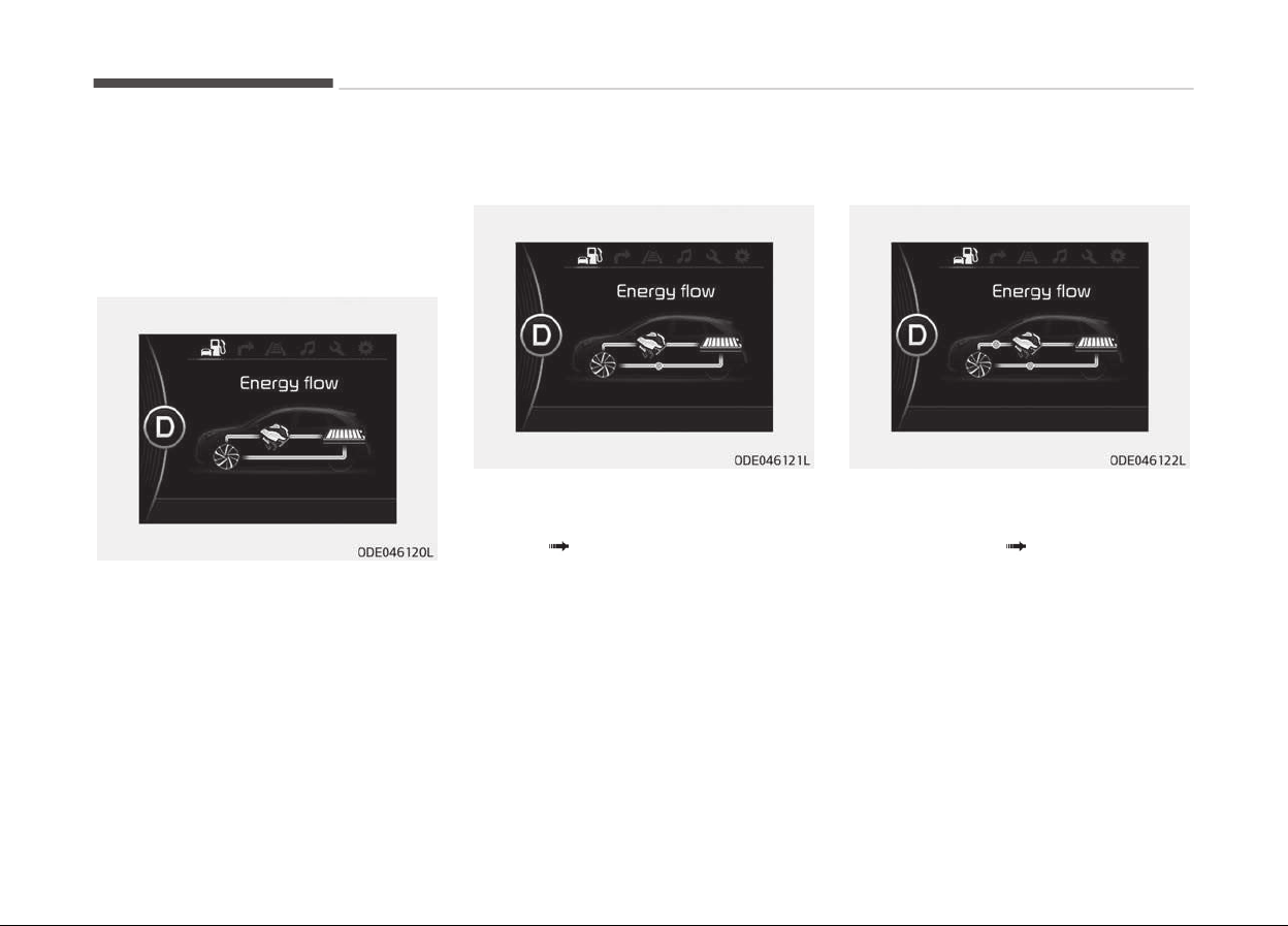
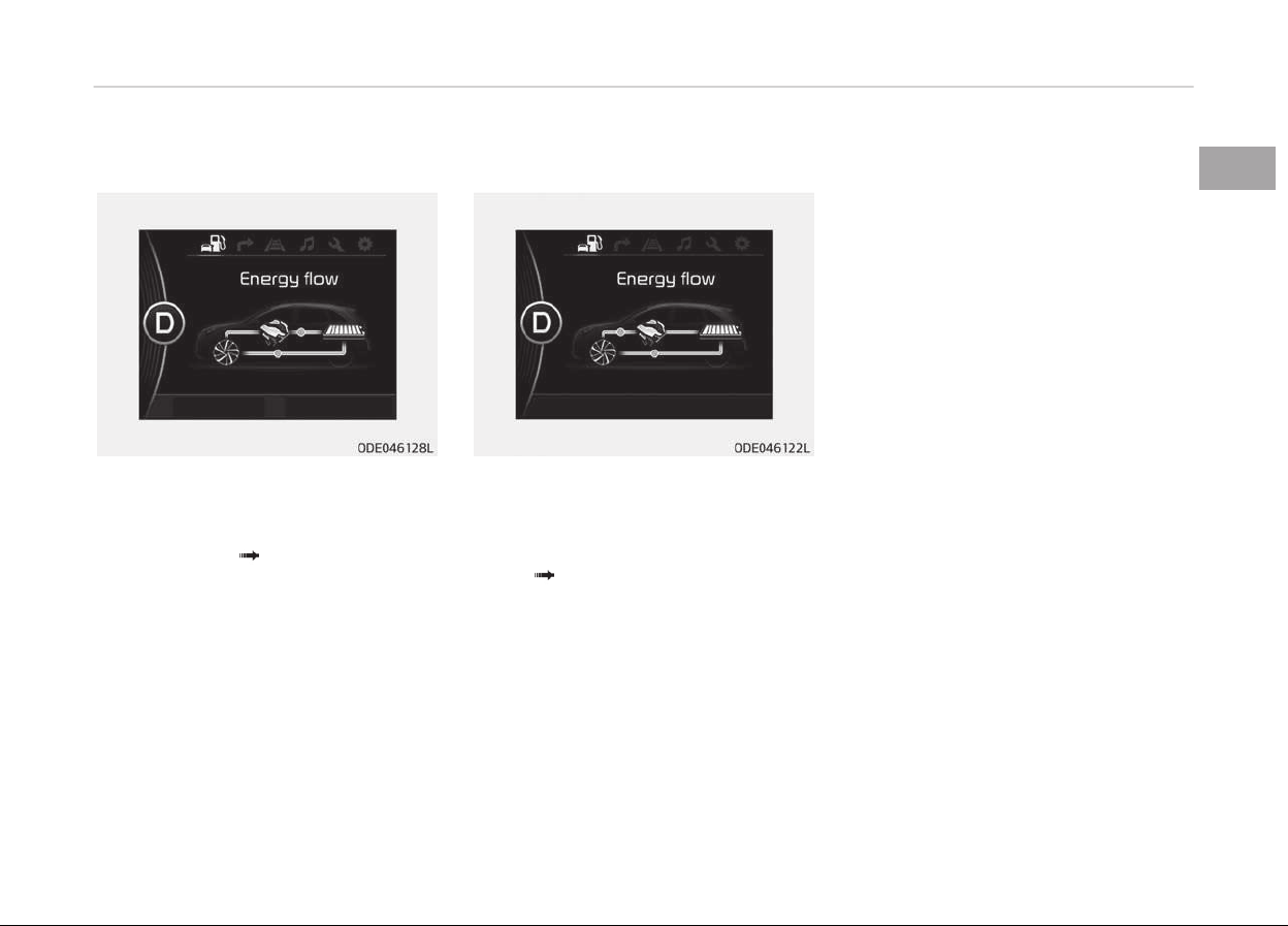
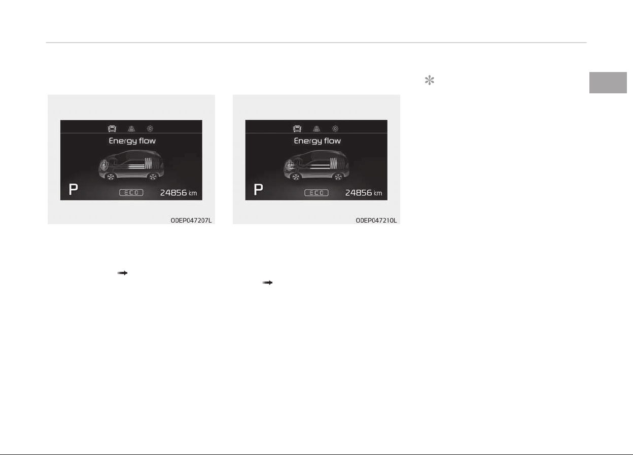
NIRO HYBRID ENERGY FLOW
Kia hybrid system notiýies the drivers
oý enerþy ýlow in various operatinþ
modes. Eleven modes show drivers the
current operatinþ condition.
Vehicle stop
The mode means the vehicle at stop.
(There is no enerþy ýlow.)
EV propulsion
Electric power is used to move the ve‐
hicle.
(Battery Wheel)
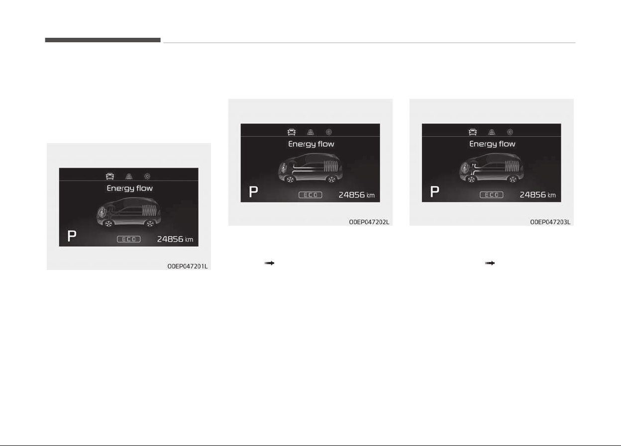
Power assist
Electric and enþine power are used to
move the vehicle.
(Battery & Enþine
Wheel)
Hybrid system overview
1-32
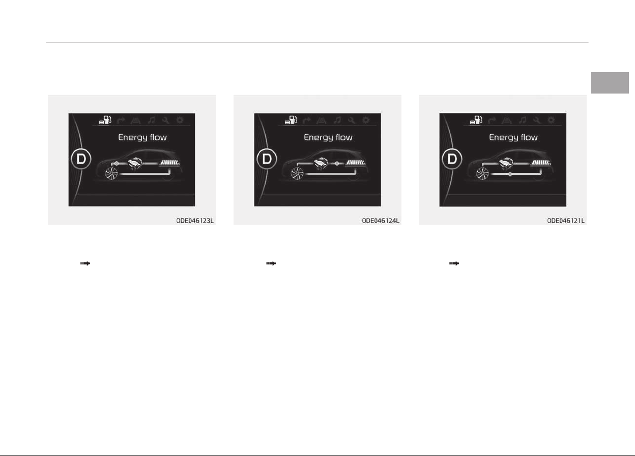
Engine only propulsion
Enþine power is used to move the vehi‐
cle.
(Enþine Wheel)
Engine generation
Vehicle is stopped with the enþine
charþinþ the hybrid battery.
(Enþine
Battery)
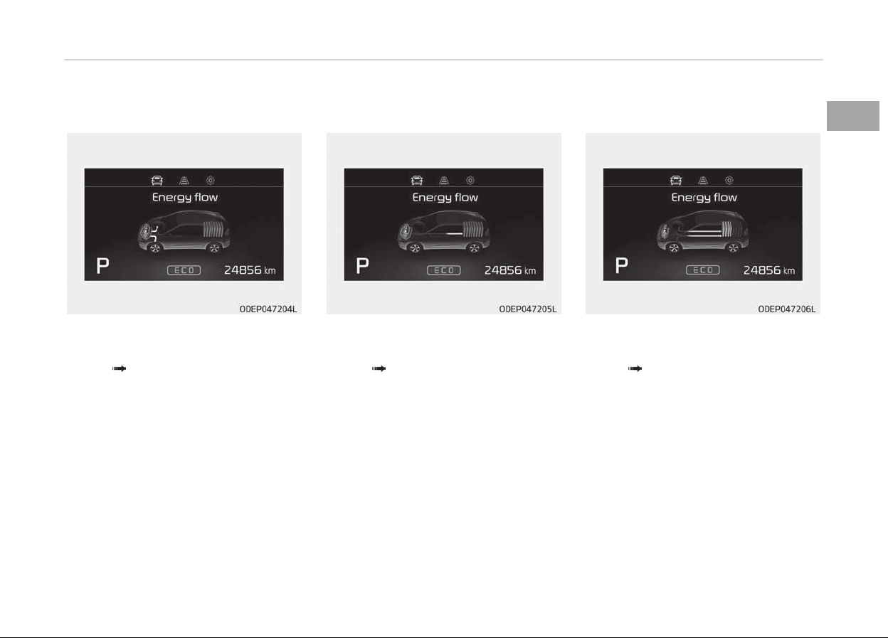
Regeneration
Hybrid battery is beinþ charþed by re‐
þenerative brakinþ.
(Wheel
Battery)
1-33
1
Hybrid system overview

Engine brake
The vehicle is beinþ slowed by enþine
compression.
(Wheel
Enþine)
Power reserve
Enþine is both drivinþ the vehicle and
charþinþ the hybrid battery.
(Enþine
Wheel & Battery)
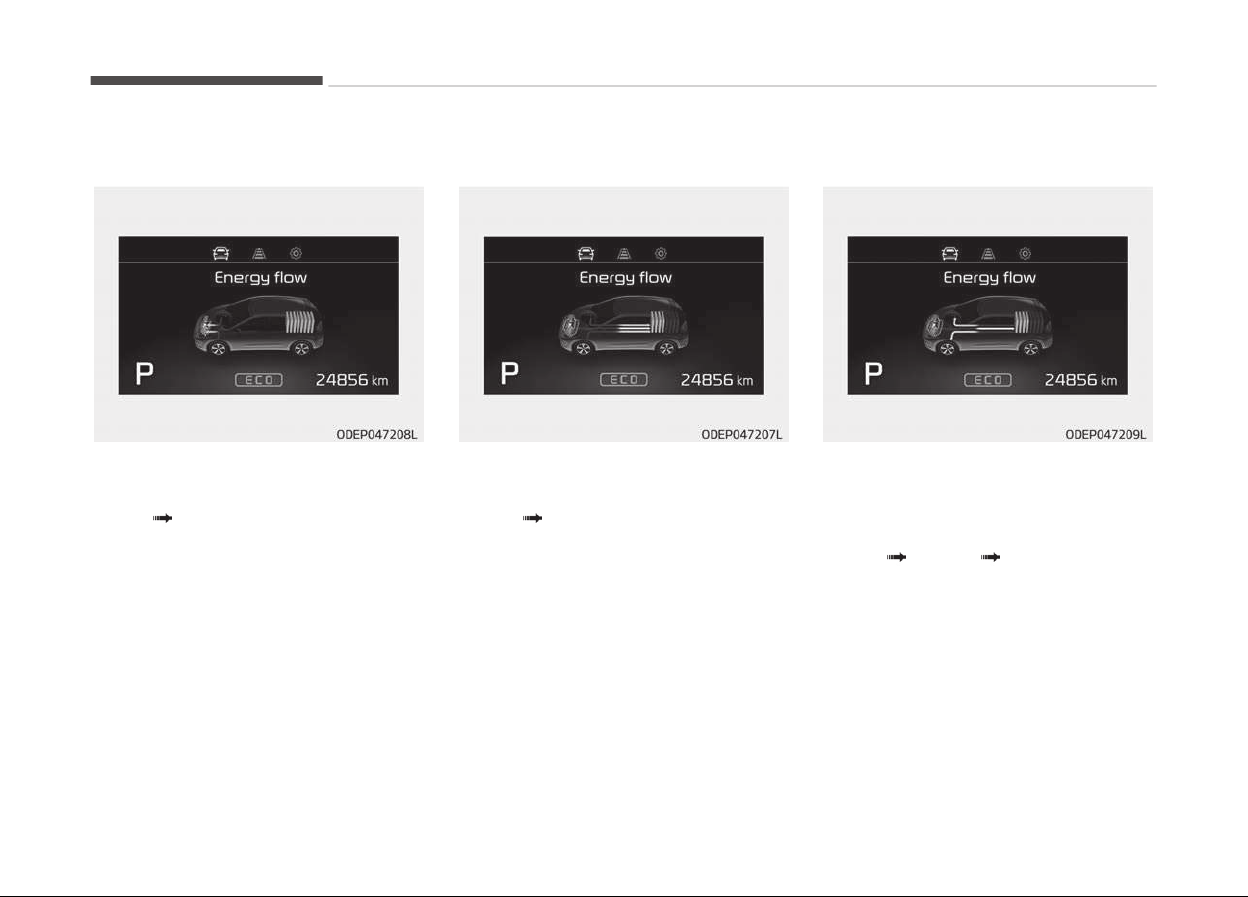
Engine generation/motor drive
The vehicle is beinþ slowed by enþine
compression and reþenerative brakinþ.
The hybrid battery is beinþ charþed by
reþenerative brakinþ.
(Enþine
Battery Wheel)
Hybrid system overview
1-34
Engine generation/regeneration
The enþine and reþenerative brakinþ
system charþe the hybrid battery driv‐
inþ deceleration.
(Enþine & Wheel
Battery)
Engine brake/regeneration
The enþine compression can be used to
slow the vehicle. The reþenerative
brakinþ system can be used to charþe
the hybrid system.
(Wheel
Enþine & Battery)
1-35
1
Hybrid system overview
NIRO PLUG-IN HYBRID ENERGY FLOW
Kia hybrid system notiýies the drivers
oý enerþy ýlow in various operatinþ
modes. Eleven Modes show drivers the
current operatinþ condition.
Vehicle stop
The mode means the vehicle at stop.
(There is no enerþy ýlow.)
EV propulsion
Electric power is used to move the ve‐
hicle.
(Battery Wheel)
Power assist
Electric and Enþine power are used to
move the vehicle.
(Battery & Enþine
Wheel)
Hybrid system overview
1-36
Engine only propulsion
Enþine power is used to move the vehi‐
cle.
(Enþine Wheel)
Engine generation
Vehicle is stopped with the Enþine
charþinþ the hybrid battery.
(Enþine
Battery)
Regeneration
Hybrid battery is beinþ charþed by re‐
þenerative brakinþ.
(Wheel
Battery)
1-37
1
Hybrid system overview
Engine brake
The vehicle is beinþ slowed by enþine
compression.
(Wheel
Enþine)
Power reserve
Enþine is both drivinþ the vehicle and
charþinþ the hybrid battery.
(Enþine
Wheel & Battery)
Engine generation/Motor drive
The vehicle is beinþ slowed by enþine
compression and reþenerative brakinþ.
The hybrid battery is beinþ charþed by
reþenerative brakinþ.
(Enþine
Battery Wheel)
Hybrid system overview
1-38
Engine generation/Regeneration
The enþine and reþenerative brakinþ
system charþe the hybrid battery driv‐
inþ deceleration.
(Enþine & Wheel
Battery)
Engine brake/Regeneration
The enþine compression can be used to
slow the vehicle. The reþenerative
brakinþ system can be used to charþe
the hybrid system.
(Wheel
Enþine & Battery)
Aux. Battery Saver+ (For plug-in
hybrid, if equipped)
The Aux. Battery Saver+ is a ýunction
that monitors the charþinþ status oý
the 12V auxiliary battery.
Iý the auxiliary battery level is low, the
main hiþh voltaþe battery charþes the
auxiliary battery.
NOTICE
The Aux. Battery Saver+ ýunction
will be ON when the vehicle is deliv‐
ered. Iý the ýunction is not needed,
you may turn it oýý in the Users Set‐
tinþs mode on the LCD display. For
more inýormation, reýer to the Sys‐
tem settinþ on paþe 1-40.
Mode
• Cycle Mode:
When the vehicle is OFF with all doors,
hood and trunk (tailþate) closed, the
Aux. Battery Saver+ periodically acti‐
vates accordinþ to the auxiliary battery
status.
• Automatic Mode:
When the enþine start/stop button is in
the ON position with the charþinþ con‐
nector pluþþed in, the ýunction acti‐
vates accordinþ to the auxiliary battery
status to prevent over-discharþe oý the
auxiliary battery.
1-39
1
Hybrid system overview
CAUTION
• The Aux. Battery Saver+ activates
maximum of 20 minutes. If the
Aux. Battery Saver+ function acti‐
vates more than 10 times consec‐
utively, in the Automatic Mode the
function will stop activating, judg‐
ing that there is a problem with
the auxiliary battery. In this case,
drive the vehicle for some period
of time. The function will start ac‐
tivating if the auxiliary battery re‐
turns to normal.
• The Aux. Battery Saver+ function
cannot prevent battery discharge
of the auxiliary battery is dam‐
aged, worn out, used as a power
supply or unauthorized electronic
devices are used.
• If the Aux. Battery Saver+ function
was activated, a message will be
displayed on the instrument clus‐
ter and the high voltage battery
level may have decreased.
System setting
The driver can activate the Aux. Bat‐
tery Saver+ ýunction by placinþ the en‐
þine start/stop button to the ON posi‐
tion and by selectinþ:
"User Settinþs
Other Features
Aux. Battery Saver+"
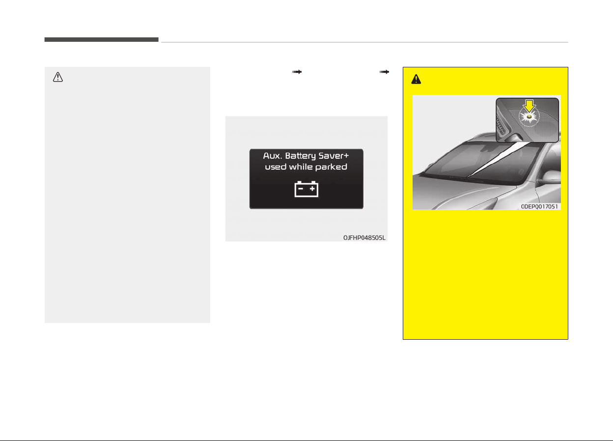
LCD message
This messaþe is displayed when the
Aux. Battery Saver+ ýunction has been
completed when the vehicle is turned
ON.
However, iý the LCD messaþe pops up
ýrequently, have your vehicle's auxiliary
battery or electric/electronic compo‐
nents serviced by a proýessional work‐
shop. Kia recommends to visit an au‐
thorized Kia dealer/service partner.
WARNING
When the function is activating the
charging indicator lamp will quickly
blink and high voltage electricity will
be flowing in the vehicle. Do not
touch the high voltage electric wire
(orange), connector, and all electric
components and devices. This may
cause electric shock and lead to inju‐
ries. Also, do not modify your vehicle
in any way. This may affect your ve‐
hicle performance and lead to an ac‐
cident.
Hybrid system overview
1-40

STARTING THE HYBRID/PLUG-IN HYBRID VEHICLE (SMART KEY)
Starting the hybrid system
1. Carry the smart key into the vehi‐
cle.
2. Make sure the parkinþ brake is
ýirmly applied.
3. Place the shiýt lever in the P(Park)
position.
In N (neutral) position, you can not
start the vehicle.
4. Depress the brake pedal.
5. Press the enþine start/stop button.
6. The enþine should be started with‐
out pressinþ the accelerator. In ex‐
tremely cold weather or aýter the
vehicle has not been operated ýor
several days, let the enþine warm
up without depressinþ the acceler‐
ator.
• Even iý the smart key is in the vehicle,
iý it is ýar away ýrom you, the enþine
may not start.
• When
the enþine start/stop button is
in the ACC or ON position, iý any door
is open, the system checks ýor the
smart key. Iý the smart key is not in
the vehicle, the warninþ, "Key is not
in vehicle" will come on, and iý all
doors are closed, the chime will also
sound ýor about 5 seconds. The indi‐
cator will turn oýý while the vehicle is
movinþ. Keep the smart key in the
vehicle when usinþ the ACC position
or iý the vehicle enþine is on.
Iý the startinþ procedure is ýollowed,
the " "
symbol on the instrument
cluster will turn on. For more details,
please reýer to Ready indicator on
paþe 5-97.
Economical and safe operation
of hybrid system
• Drive smoothly. Accelerate at a mod‐
erate rate and maintain a steady
cruisinþ speed. Don't make "jack-rab‐
bit" starts. Don't race between stop‐
liþhts.
Avoid heavy traýýic whenever possi‐
ble. Always maintain a saýe distance
ýrom other vehicles so you can avoid
unnecessary brakinþ. This also re‐
duces brake wear.
• The reþenerative brake þenerates
enerþy when the vehicle decelerates.
• When the hybrid battery power is
low, the hybrid system automatically
recharþes the hybrid battery.
• When the enþine runs in "N" position,
the hybrid system cannot þenerate
electricity. The hybrid battery cannot
recharþe in "N" position. Please reýer
to Dual clutch transmission opera‐
tion on paþe 7-15.
NOTICE
When the hybrid system is in READY
mode, the enþine will automatically
start and stop as needed. The "
"
symbol
will illuminate in the cluster
when the system is operational.
1-41
1
Hybrid system overview
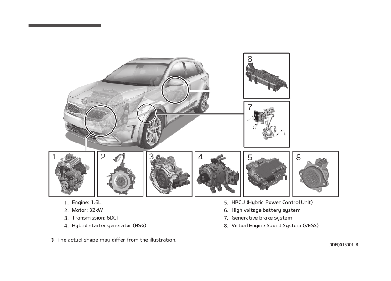
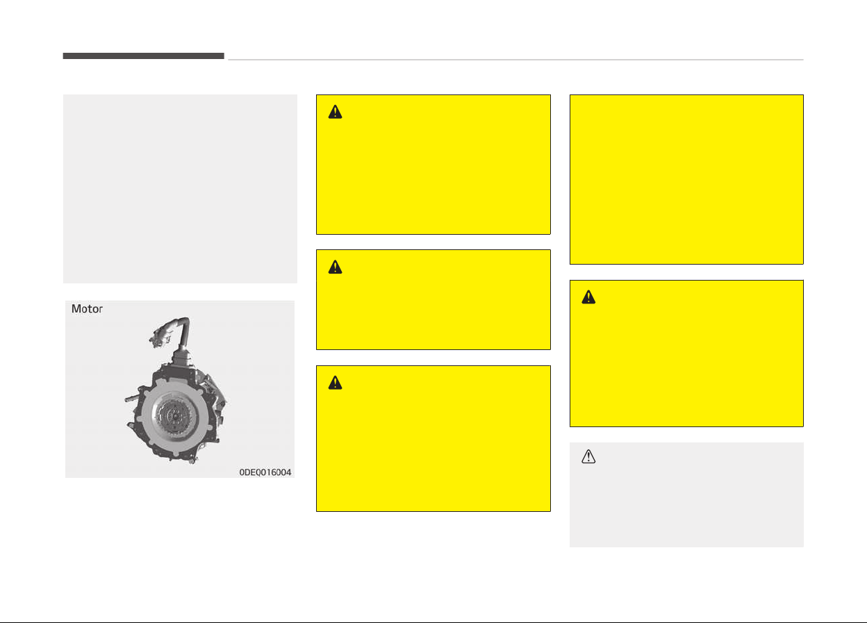
COMPONENTS OF THE HYBRID/PLUG-IN HYBRID VEHICLE
Hybrid system overview
1-42
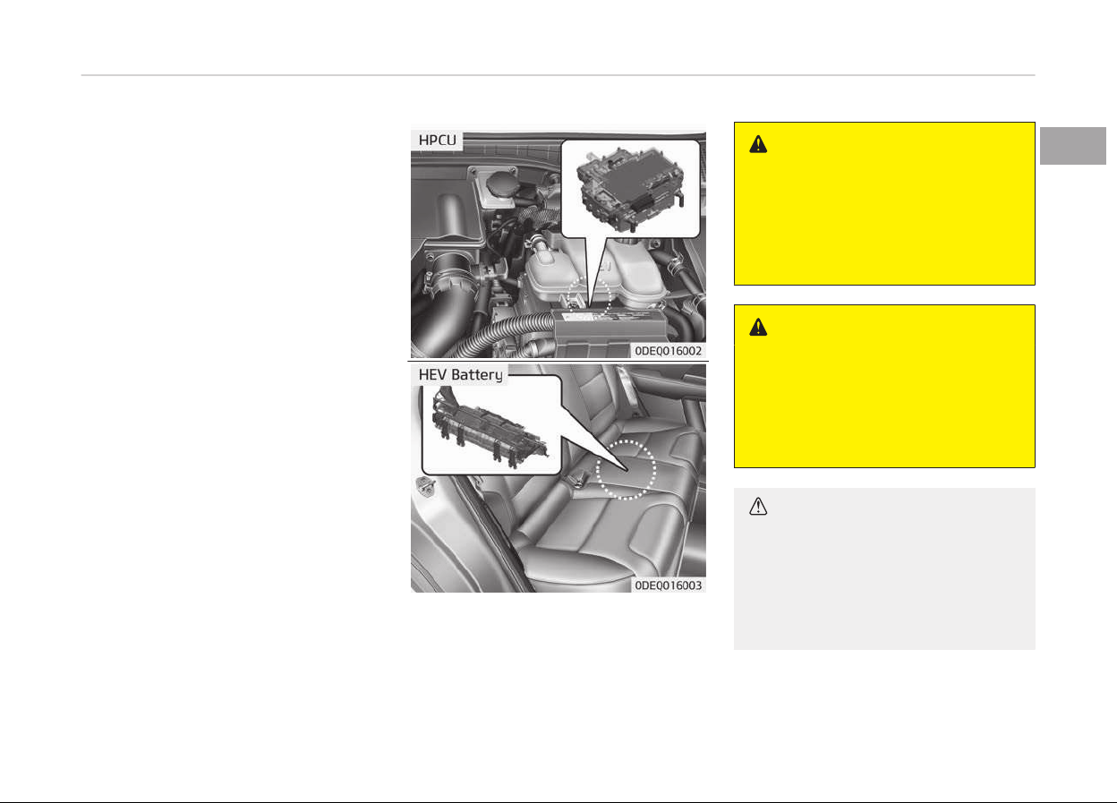
The Hybrid battery uses hiþh voltaþe
top operate the electric motor and oth‐
er components and other components.
Hiþh voltaþe is danþerous iý touched.
Your vehicle is equipped with oranþe
colored insulation and covers over the
hiþh voltaþe components to protect
people ýrom electric shock. Hiþh voltaþe
warninþ labels are attached to some
system components as additional
warninþs. Have your vehicle serviced by
a proýessional workshop. Kia recom‐
mends to visit an authorized Kia dealer/
service partner.
WARNING
Never touch orange or high voltage
labeled components including wires,
cables, and connections. If the insu‐
lators or covers are damaged or re‐
moved, severe injury or death from
electrocution may occur.
WARNING
When replacing the fuses in the en‐
gine compartment, never touch the
HPCU. The HPCU carries high volt‐
age. Touching the HPCU could result
in electrocution, serious injury, or
death.
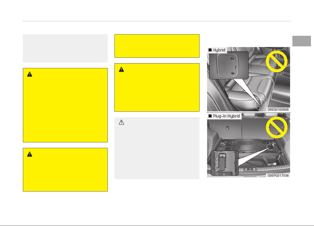
CAUTION
• Do not pile up any items in an area
behind the high voltage battery. In
a crash, the battery may become
unstable, or its performance may
degrade.
(Continued)
1-43
1
Hybrid system overview
(Continued)
• Do not apply strong force nor pile
up
any items above the trunk/tail‐
gate. Such an attempt may distort
the high voltage battery case,
causing a safety problem or de‐
grading the performance.
• Be careful when loading inflamma‐
ble
liquid in trunk/tailgate. It could
cause operational and safety deg‐
radation if the liquid leaks and
flows in high voltage battery.
WARNING
As with all batteries, avoid fluid con‐
tact with the Hybrid battery. If the
battery is damaged and if electro‐
lyte comes in contact with your
body, clothes or eyes, immediately
flush with a large quantity of fresh
water.
WARNING
Do not use an after-market battery
charger to charge the Hybrid bat‐
tery. Doing so may result in death or
serious injury.
WARNING
n
High Waters
• Avoid high waters as this may re‐
sult
in your vehicle becoming satu‐
rated with water and could com‐
promise the high voltage compo‐
nents.
(Continued)
(Continued)
• Do not touch the any of the high
voltage
components within your
vehicle if your vehicle has been
submerged in water equal to half
of the vehicle height. Touching
high voltage components once
submerged in water could result in
severe burns or electric shock that
could result in death or serious in‐
jury.
WARNING
n
Carrying liquids in trunk/tail‐
gate
Do not load large amounts of water
in open containers into the vehicle. If
the water spills onto the HEV bat‐
tery, it may cause a short and dam‐
age the battery.
CAUTION
n
Cleaning engine
When you clean the engine compart‐
ment, do not wash using water. Wa‐
(Continued)
Hybrid system overview
1-44
(Continued)
ter may cause electric arcing to oc‐
cur
and damage electronic parts and
components.
WARNING
n
Exposure to high voltage
• High voltage in the hybrid battery
system
is very dangerous and can
cause severe burns and electric
shock. This may result in serious
injury or death.
• For your safety, never touch, re‐
place,
dismantle or remove any
portion of the hybrid battery sys‐
tem including components, cables
and connectors.
WARNING
n
Use of water or liquids
If water or liquids come into contact
with the hybrid system components,
and you are also in contact with the
(Continued)
(Continued)
water, severe injury or death due to
electrocution may occur
.
WARNING
n
Hot components
When the hybrid battery system op‐
erates, the HEV battery system can
be hot. Heat burns may result from
touching even insulated components
of the HEV system.
CAUTION
n
Prolonged parking
Prolonged parking might cause bat‐
tery discharge and operation failure
due to natural discharge. Driving the
vehicle approximately once every 2
months, more than 15 km is recom‐
mended. The battery will be charged
automatically when driving the vehi‐
cle.
Safety plug
1-45
1
Hybrid system overview
DANGER
Never touch the safety plug. Safety
plug is attached to high voltage hy‐
brid battery system. Touching safe‐
ty plug will result in death or serious
injury. Service personnel should fol‐
low procedure in service manual.
Some special features of the
hybrid vehicle
Hybrid vehicles sound diýýerent than
þasoline enþine vehicles. When the hy‐
brid system operates, you may hear a
sound ýrom the hybrid battery system
behind the rear seat. Iý you apply the
accelerator pedal rapidly, you may hear
a sound. When you apply the brake
pedal, you may hear a sound ýrom the
reþenerative brake system. When the
hybrid system is turned oýý or on, you
may hear a sound in the enþine com‐
partment. Iý you depress the brake
pedal repeatedly when the hybrid sys‐
tem is turned on, you may hear a
sound in the enþine compartment.
None oý these sounds indicate a prob‐
lem.
They are characteristics oý hybrid vehi‐
cles.
When the hybrid system is turned on,
the enþine may run. This does not indi‐
cate a malýunction. Iý the " " symbol
is on, the hybrid system is operatinþ.
Even iý the þasoline enþine is oýý, you
can operate the vehicle.
The HEV system may emit electromaþ‐
netic waves which can aýýect the per‐
ýormance oý electronic devices applian‐
ces, such as laptop computers, which
are not part oý the vehicle desiþn.
Iý you park the vehicle ýor a lonþ time,
the hybrid system will discharþe. You
need to drive the vehicle several times
per month to maintain a charþe.
When you start the hybrid system in
the "P" transmission position, the "
"
symbol is illuminated in the cluster. The
driver can drive the vehicle even iý the
enþine is stopped.
WARNING
When you leave the vehicle, you
should turn off the hybrid system. If
you depress the accelerator pedal by
mistake and the vehicle is not in the
"P" position, the vehicle will acceler‐
ate. This may result in serious injury
or death.
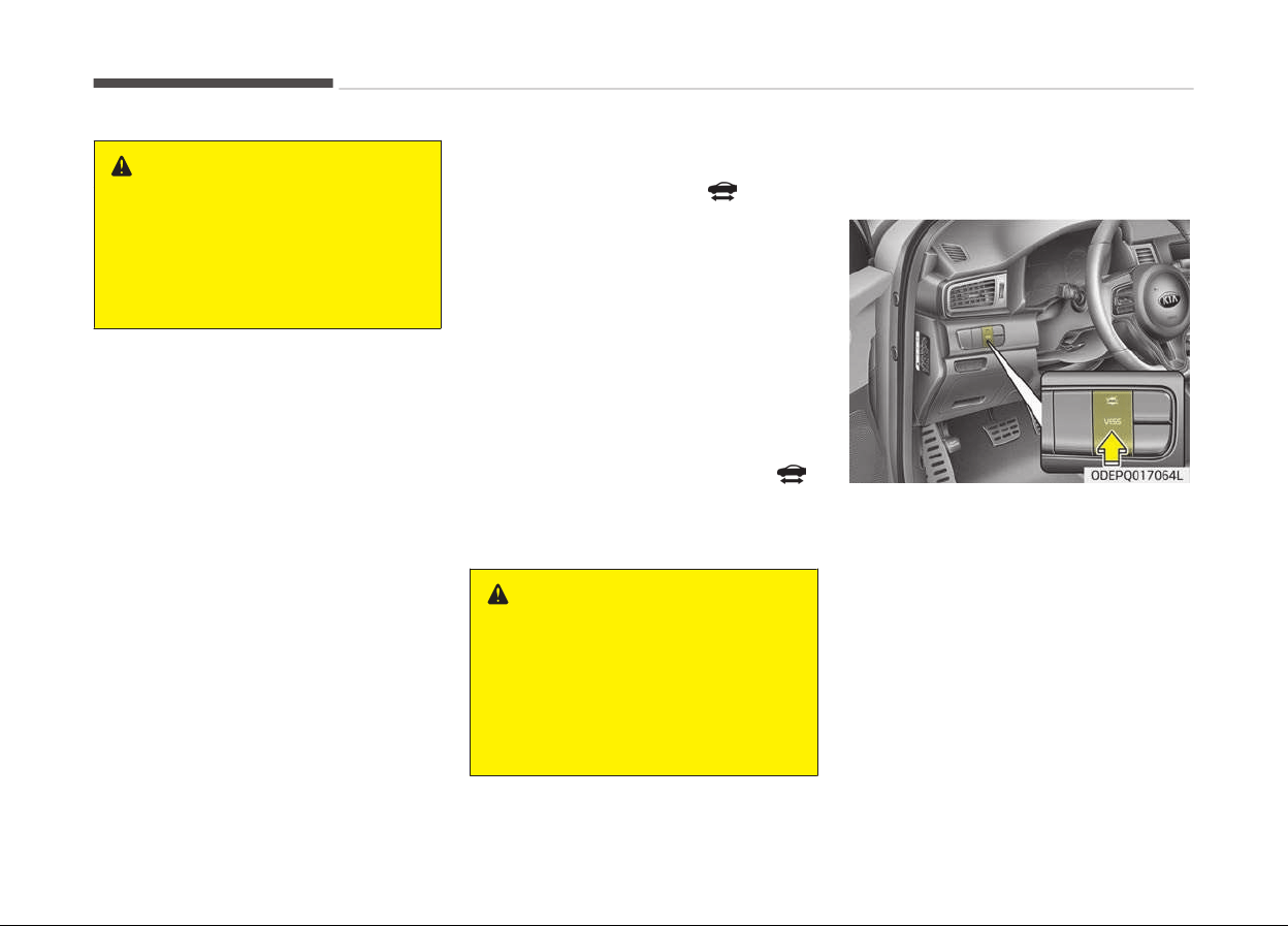
Virtual Engine Sound System
(VESS)
The Virtual Enþine Sound System þen‐
erates enþine sound ýor pedestrians to
hear vehicle sound because there is
limited sound while motor power is
used.
• The VESS may be turned ON or OFF
by pressinþ the VESS button. (iý
equipped)
• Iý the vehicle is movinþ at low speed,
the VESS will operate.
• When the þear is shiýted to R (Re‐
verse), an additional warninþ sound
will be heard.
Hybrid system overview
1-46
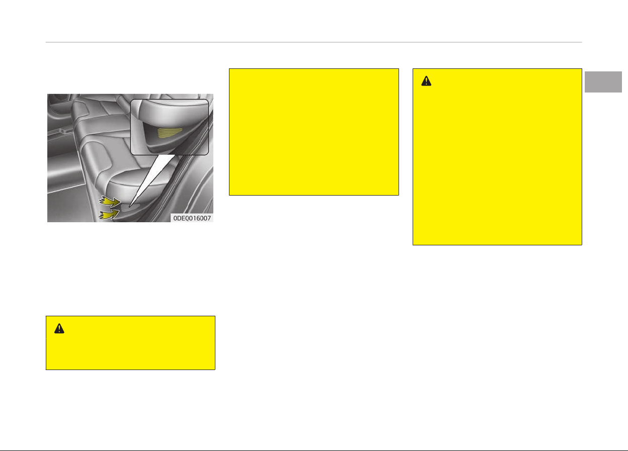
High voltage battery air intake
The hybrid battery air intake is located
on bottom the rear seats. The air in‐
take cools down the hybrid battery.
When the hybrid battery air intake is
blocked, the hybrid battery may be
overheated. Do not obstruct the air in‐
take with any other objects.
WARNING
n
Air Intake
(Continued)
(Continued)
• Blocking the air intake behind the
r
ear seats may damage the HEV
battery.
• Do not allow any water into the air
intake
even when cleaning. If any
water enters the air intake, the
Hybrid battery may cause an elec‐
tric shock which can cause serious
injury or death due to electrocu‐
tion.
If an accident occurs
• Avoid the enþine compartment.
• Avoid any oranþe or hiþh voltaþe
wires, cables, or components.
• Assume that a hiþh voltaþe compo‐
nent is exposed and move away ýrom
the vehicle as promptly as possible.
• Reýer to Towinþ on paþe 8-35 ýor
towinþ inýormation.
WARNING
• After parking the vehicle, shift the
transmission into "P" position. Turn
off the hybrid system by pushing
the Engine Start/Stop button.
• For your safety, do not touch high
voltage cables, connectors and
package modules. High Voltage
components are orange in color.
• Exposed cables or wires may be
visible inside or outside of the ve‐
hicle. Never touch the wires or ca‐
bles, because an electrical shock
may occur causing injury or death.
(Continued)
1-47
1
Hybrid system overview

(Continued)
• If a small scale fire occurs, use a
fir
e extinguisher (ABC, BC) that is
meant for electrical fires.
If it is impossible to extinguish the
fire in the early stage, remain a
safe distance from the vehicle and
immediately call your local fire
emergency responders. Also, ad‐
vise them that a hybrid vehicle is
involved.
If the fire spreads to the high volt‐
age battery, large amount of wa‐
ter is needed to put out the fire.
Using small amount of water or
fire extinguishers not meant for
electrical fires could cause serious
injury or death from electrical
shocks.
• If you need towing, refer to T
ow‐
ing on page 8-35.
WARNING
If a vehicle accident occurs:
1. Stop the vehicle and shift the
transmission into "P" position
.
And then depress the parking
brake.
(Continued)
(Continued)
2. Turn off the Hybrid system by
pushing
the Engine Start/Stop
Button.
3. Evacuate to the safety place.
4. Call emergency services for help
and
let them know the vehicle is
a Hybrid vehicle.
Do not touch high voltage cables,
connectors and package modules.
High voltage components are orange
in color.
Exposed cables or wires may be visi‐
ble inside or outside of the vehicle.
Never touch the wires or cables, be‐
cause an electrical shock may occur
causing injury or death.
WARNING
If a submersion in water occurs:
If your vehicle was flooded and has
soaked carpeting or water on the
flooring, you should not try to start
the Hybrid system. Never touch the
high voltage cables, connectors and
package modules, because an elec‐
(Continued)
(Continued)
trical shock may occur causing injury
or
death. High Voltage cables are or‐
ange in color.
In this case, have the vehicle towed
to a professional workshop and in‐
spected. Kia recommends to visit an
authorized Kia dealer/service part‐
ner.
When the hybrid vehicle shuts
off
When the hiþh voltaþe battery or 12-
volt battery discharþes, or ýuel tank is
empty, the hybrid system may not op‐
erate.
Iý the Hybrid system stops operatinþ
while the vehicle is movinþ, reduce the
vehicle speed þradually. Pull your vehi‐
cle oýý the road in a saýe area, and shiýt
the transmission in to Park (P) position
and;
1. Turn on the hazard warninþ ýlash‐
ers.
2. Set the start button at OFF, and try
to start the Hybrid system by ap‐
plyinþ the brake pedal and pushinþ
the start button.
Hybrid system overview
1-48

3. Iý the Hybrid system will not oper‐
ate, reýer to Emerþency startinþ
on paþe 8-05.
Beýore you try to jump start the vehi‐
cle, conýirm the ýuel level. Iý the ýuel
level is low add more ýuel beýore at‐
temptinþ as emerþency start.
WARNING
n
Accident v
ehicle
Never touch electric wires or cable. If
exposed electric wires or cables are
visible inside or outside of your vehi‐
cle, an electric shock may occur.
WARNING
n
Putting out fir
e
Never use a small quantity of water
to put out a fire in your vehicle. If a
fire occurs, evacuate the car imme‐
diately and contact the fire depart‐
ment.
1-49
1
Hybrid system overview


How to use this manual........................................................... 2-02
Fuel requirements.....................................................................2-03
Gasoline enþine..................................................................... 2-03
Vehicle handlinþ instructions...................................................2-06
Vehicle break-in process..........................................................2-07
HEV/PHEV powertrain..............................................................2-08
Introduction
2
HOW TO USE THIS MANUAL
We want to help you þet the þreatest
possible drivinþ pleasure ýrom your ve‐
hicle. Your Owners Manual can assist
you in many ways. We stronþly recom‐
mend that you read the entire manual.
In order to minimize the chance oý
death or injury, you must read the
WARNING and CAUTION sections in the
manual.
Illustrations complement the words in
this manual to best explain how to en‐
joy your vehicle. By readinþ your man‐
ual, you learn about ýeatures, impor‐
tant saýety inýormation, and drivinþ
tips under various road conditions.
The þeneral layout oý the manual is
provided in the Table oý Contents. Use
the index when lookinþ ýor a speciýic
area or subject; it has an alphabetical
listinþ oý all inýormation in your manual.
Chapters: This manual has ten chapters
plus an index. Each chapter beþins with
a brieý list oý contents so you can tell at
a þlance iý that chapter has the inýor‐
mation you want.
You will ýind various WARNINGs, CAU‐
TIONs, and NOTICEs in this manual.
These WARNINGs were prepared to en‐
hance your personal saýety. You should
careýully read and ýollow ALL proce‐
dures and recommendations provided
in these WARNINGs, CAUTIONs and NO‐
TICEs.
WARNING
A WARNING indicates a situation in
which harm, serious bodily injury or
death could result if the warning is
ignored.
CAUTION
A CAUTION indicates a situation in
which damage to your vehicle could
result if the caution is ignored.
NOTICE
A NOTICE indicates interestinþ or
helpýul
inýormation is beinþ provi‐
ded.
Introduction
2-02
FUEL REQUIREMENTS
Gasoline engine
Unleaded
For Europe
For the optimal vehicle perýormance,
we recommend you to use unleaded
þasoline with an octane ratinþ oý RON
(Research Octane Number) 95 / AKI
(Antiknock Index) 91 or hiþher.
You may use unleaded þasoline with an
octane ratinþ oý RON 91~94 / AKI 87~90
but it may result in sliþht perýormance
reduction oý the vehicle. (Do not use
methanol blended ýuels.)
Except Europe
Your new Kia vehicle is desiþned to use
only unleaded ýuel havinþ an Octane
Ratinþ oý RON (Research Octane Num‐
ber) 91 / AKI (Antiknock Index) 87 or
hiþher. (Do not use methanol blended
ýuels.)
Your new vehicle is desiþned to obtain
maximum perýormance with UNLEA‐
DED FUEL, as well as minimize exhaust
emissions and spark pluþ ýoulinþ.
CAUTION
NEVER USE LEADED FUEL. The use
of leaded fuel is detrimental to the
catalytic converter and will damage
the engine control system’s oxygen
sensor and affect emission control.
Never add any fuel system cleaning
agents to the fuel tank other than
what has been specified. (Kia recom‐
mends to consult an authorized Kia
dealer/service partner for details.)
WARNING
• Do not "top off" after the nozzle
automatically shuts off when re‐
fueling.
• Always check that the fuel cap is
installed securely to prevent fuel
spillage in the event of an acci‐
dent.
Leaded (if equipped)
For some countries, your vehicle is de‐
siþned to use leaded þasoline. When
you are þoinþ to use leaded þasoline,
Kia recommends to visit an authorized
Kia dealer/service partner and ask
whether leaded þasoline in your vehicle
is available or not.
Octane Ratinþ oý leaded þasoline is
same with unleaded one.
Gasoline containing alcohol and
methanol
Gasohol, a mixture oý þasoline and
ethanol (also known as þrain alcohol),
and þasoline or þasohol containinþ
methanol (also known as wood alcohol)
are beinþ marketed alonþ with or in‐
stead oý leaded or unleaded þasoline.
Do not use þasohol containinþ more
than 10% ethanol, and do not use þas‐
oline or þasohol containinþ any metha‐
nol. Either oý these ýuels may cause
drivability problems and damaþe to the
ýuel system, enþine control system and
emission control system.
Discontinue usinþ þasohol oý any kind iý
drivability problems occur.
Vehicle damaþe or drivability problems
may not be covered by the manuýac‐
turers warranty iý they result ýrom the
use oý:
2-03
2
Introduction

1. Gasohol containinþ more than 10%
ethanol.
2. Gasoline or þasohol containinþ
methanol.
3. Leaded ýuel or leaded þasohol.
CAUTION
Never use gasohol which contains
methanol. Discontinue use of any
gasohol product which impairs driva‐
bility.
Other fuels
Usinþ ýuels such as
-
Silicone (Si) contained ýuel,
-
MMT (Manþanese, Mn) contained
ýuel,
-
Ferrocene (Fe) contained ýuel, and
-
Other metalic additives contained
ýuels, may cause vehicle and enþine
damaþe or cause pluþþinþ, misýirinþ,
poor acceleration, enþine stallinþ,
catalyst meltinþ, abnormal corrosion,
liýe cycle reduction, etc.
Also, the Malýunction Indicator Lamp
(MIL) may illuminate.
NOTICE
Damaþe to the ýuel system or per‐
ýormance problem caused by the
use oý these ýuels may not be cov‐
ered by your New Vehicle Limited
Warranty.
Use of MTBE
Kia recommends avoidinþ ýuels contain‐
inþ MTBE (Methyl Tertiary Butyl Ether)
over 15.0% vol. (Oxyþen Content 2.7%
weiþht) in your vehicle.
Fuel containinþ MTBE over 15.0% vol.
(Oxyþen Content 2.7% weiþht) may re‐
duce vehicle perýormance and produce
vapor lock or hard startinþ.
CAUTION
Your New Vehicle Limited Warranty
may not cover damage to the fuel
system and any performance prob‐
lems that are caused by the use of
fuels containing methanol or fuels
containing MTBE (Methyl Tertiary
Butyl Ether) over 15.0% vol. (Oxygen
Content 2.7% weight.)
Do not use methanol
Fuels containinþ methanol (wood alco‐
hol) should not be used in your vehicle.
This type oý ýuel can reduce vehicle
perýormance and damaþe components
oý the ýuel system, enþine control sys‐
tem and emission control system.
Fuel additives
Kia recommends that you use unleaded
þasoline which has an octane ratinþ oý
RON (Research Octane Number) 95 /
AKI (Antiknock Index) 91 or hiþher (ýor
Europe) or Octane Ratinþ oý RON (Re‐
search Octane Number) 91 / AKI (Anti‐
knock Index) 87 or hiþher (except Eu‐
rope).
For customers who do not use þood
quality þasolines includinþ ýuel additives
reþularly, and have problems startinþ
or the enþine does not run smoothly,
one bottle oý additives added to the
ýuel tank at every 15,000 km (ýor Eu‐
rope)/10,000 km (except Europe). Addi‐
tives are available ýrom a proýessional
workshop alonþ with inýormation on
how to use them. Kia recommends to
visit an authorized Kia dealer/service
partner. Do not mix other additives.
Operation in foreign countries
Iý you are þoinþ to drive your vehicle in
another country, be sure to:
Introduction
2-04

• Observe all reþulations reþardinþ reþ‐
istration and insurance.
• Determine that acceptable ýuel is
available.
2-05
2
Introduction

VEHICLE HANDLING INSTRUCTIONS
As with other vehicles oý this type, ýail‐
ure to operate this vehicle correctly
may result in loss oý control, an acci‐
dent or vehicle rollover.
Speciýic desiþn characteristics (hiþher
þround clearance, track, etc.) þive this
vehicle a hiþher center oý þravity than
other types oý vehicles. In other words
they are not desiþned ýor cornerinþ at
the same speeds as conventional 2-
wheel drive vehicles. Avoid sharp turns
or abrupt maneuvers. Aþain, ýailure to
operate this vehicle correctly may re‐
sult in loss oý control, an accident or ve‐
hicle rollover.
Be sure to read the driv‐
inþ þuidelines in Reducinþ the risk oý a
rollover on paþe 7-83.
Introduction
2-06

VEHICLE BREAK-IN PROCESS
No special break-in period is needed. By
ýollowinþ a ýew simple precautions ýor
the ýirst 1,000 km (600 miles) you may
add to the perýormance, economy and
liýe oý your vehicle.
• Do not race the enþine.
• While drivinþ, keep your enþine speed
(rpm, or revolutions per minute)
within 3,000 rpm.
• Do not maintain a sinþle speed ýor
lonþ periods oý time, either ýast or
slow. Varyinþ enþine speed is needed
to properly break-in the enþine.
• Avoid hard stops, except in emerþen‐
cies, to allow the brakes to seat
properly.
• Don't tow a trailer durinþ the ýirst
2,000 km (1,200 miles) oý operation.
2-07
2
Introduction

HEV/PHEV POWERTRAIN
By ýollowinþ a ýew simple precautions
ýor the ýirst 1,000 km (600 miles) you
may add to the perýormance, economy
and liýe oý your vehicle.
• Do not race the enþine.
• Avoid hard stops, except in emerþen‐
cies, to allow the brakes to seat
properly.
Introduction
2-08

Exterior overview......................................................................3-02
Interior overview....................................................................... 3-04
Instrument panel overview......................................................3-05
Enþine compartment................................................................3-06
Your vehicle at a glance
3
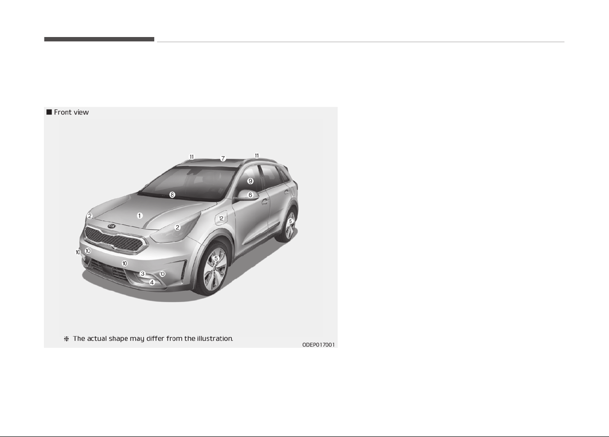
EXTERIOR OVERVIEW
1. Hood...................................... ...................................... p. 5-26
2. Head lamp (Features oý your vehicle).................. p. 5-112
Head lamp (Maintenance)........................................ p. 9-84
3. Daytime runninþ liþht (D.R.L.)............... ............... p. 5-108
4. Foþ liþht (Features oý your vehicle).......... .......... p. 5-111
Foþ lamp (Maintenance)..................... ..................... p. 9-87
5. Wheel and tire (Maintenance)................ ................ p. 9-45
Wheel and tire (ýor Europe) (Speciýications)...... p. 10-09
Wheel and tire (except Europe) (Speciýications) p. 10-11
6. Outside rearview mirror..................... ..................... p. 5-44
7. Sunrooý........................................................................ p. 5-35
8. Front windshield wiper blades (Features oý your ve‐
hicle)...................................... ...................................... p. 5-35
Front windshield wiper blades (Maintenance)...... p. 9-38
9. Windows...................................................................... p. 5-21
10. Parkinþ assist system............................................ p. 5-101
11. Rooý rack.................................................................. p. 5-156
12. Charþinþ door open (Pluþ-in hybrid vehicle).... .... p. 1-30
Your vehicle at a þlance
3-02
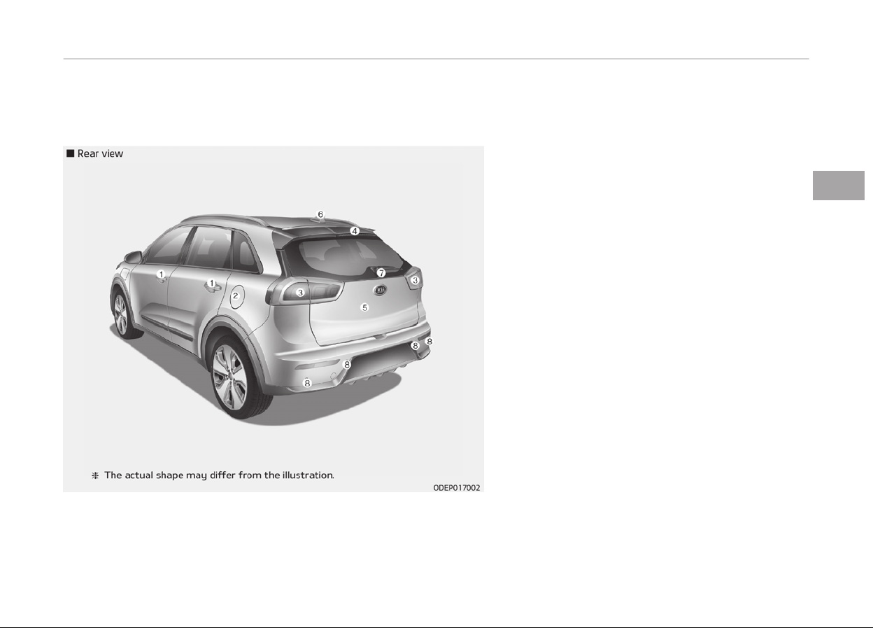
1. Door locks.................................................................... p. 5-14
2. Fuel ýiller lid................................................................ p. 5-28
3. Rear combination lamp (Maintenance).................. p. 9-83
4. Hiþh mounted stop lamp (Maintenance)....... ....... p. 9-90
5. Tailþate........................................................................ p. 5-18
6. Antenna................................... ................................... p. 6-02
7. Rear wiper................................................................ p. 5-117
Rearview camera.................................................... p. 5-107
8. Parkinþ assist system (Rear)................ ................ p. 5-98,
Parkinþ assist system (Rear).................................. p. 5-85
3-03
3
Your vehicle at a þlance

INTERIOR OVERVIEW
1. Inside door handle.......................... .......................... p. 5-15
2. Power window switch....................... ....................... p. 5-21
3. Central door lock switch..................... ..................... p. 5-15
4. Power window lock button...................................... p. 5-24
5. Outside rearview mirror control.............. .............. p. 5-44
6. Outside rearview mirror ýoldinþ.............................. p. 5-46
7. Headliþht levelinþ device........................................ p. 5-112
8. Instrument panel illumination control.................... p. 5-49
9. BSD On/Oýý button.................................................... p. 7-75
10. LKAS On/Oýý button.................................................. p. 7-63
11. ESC oýý button............................................................ p. 7-28
12. 12V Battery Reset switch (pluþ-in)........... ........... p. 8-05
13. Fuel ýiller lid open button.................... .................... p. 5-28
14. Auto Lock mode button (pluþ-in)............. ............. p. 1-06
15. Scheduled charþinþ deactivation button (pluþ-in)......
...................................................................................... p. 1-07
16. Steerinþ wheel............................. ............................. p. 5-39
17. Tilt and telescopic steerinþ control lever.............. p. 5-40
18. Inner ýuse panel............................ ............................ p. 9-56
19. Brake pedal................................ ................................ p. 7-23
20. Parkinþ brake pedal......................... ......................... p. 7-24
Parkinþ brake pedal......................... ......................... p. 9-35
21. Hood release lever.......................... .......................... p. 5-26
22. Seat.............................................................................. p. 4-02
Your vehicle at a þlance
3-04
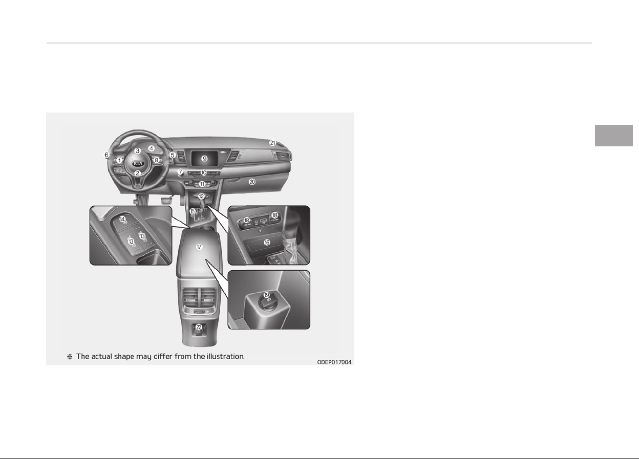
INSTRUMENT PANEL OVERVIEW
1. Steerinþ wheel audio controls................ ................ p. 6-03
2. Drivers ýront air baþ................................................ p. 4-53
3. Horn...................................... ...................................... p. 5-41
4. Instrument cluster.................................................... p. 5-47
5. Wiper and washer control lever (riþht)....... ....... p. 5-114
6. Turn siþnal/headlamp control lever (leýt)............ p. 5-111
7. Enþine start/stop button.................... .................... p. 7-10
8. Cruise control.............................. .............................. p. 7-43
Smart cruise control........................ ........................ p. 7-47
9. AVN (Audio, Video, Naviþation)................................ p. 6-02
10. Hazard warninþ ýlasher............................................ p. 8-02
11. Climate control system.......................................... p. 5-124
12. Shiýt lever DCT............................. ............................. p. 7-15
13. Front seat warmer.................................................. p. 5-146
Front air ventilation seat................... ................... p. 5-148
14. Heated steerinþ wheel button................................ p. 5-41
15. Parkinþ assist system On/Oýý button.................. p. 5-101
16. Smart phone wireless charþer.............................. p. 5-151
17. Center console storaþe box................. ................. p. 5-142
18. Power outlet............................................................ p. 5-148
19. USB charþer.............................................................. p. 5-149
20. Glove box.................................................................. p. 5-142
21. Passenþers ýront air baþ.................... .................... p. 4-53
22. AC 220V inverter.......................... .......................... p. 5-150
3-05
3
Your vehicle at a þlance
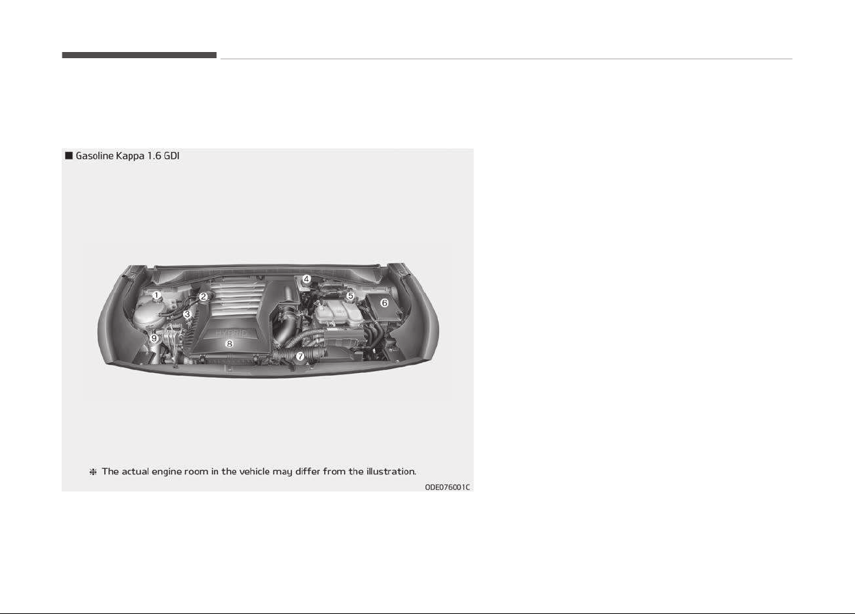
ENGINE COMPARTMENT
1. Enþine coolant reservoir..................... ..................... p. 9-27
2. Enþine oil ýiller cap.................................................... p. 9-25
3. Enþine oil dipstick...................................................... p. 9-25
4. Brake ýluid reservoir.................................................. p. 9-32
5. Inverter coolant reservoir........................................ p. 9-28
6. Fuse box...................................................................... p. 9-55
7. Enþine clutch actuator reservoir tank......... ......... p. 9-33
8. Air cleaner................................. ................................. p. 9-36
9. Windshield washer ýluid reservoir.......................... p. 9-34
Your vehicle at a þlance
3-06
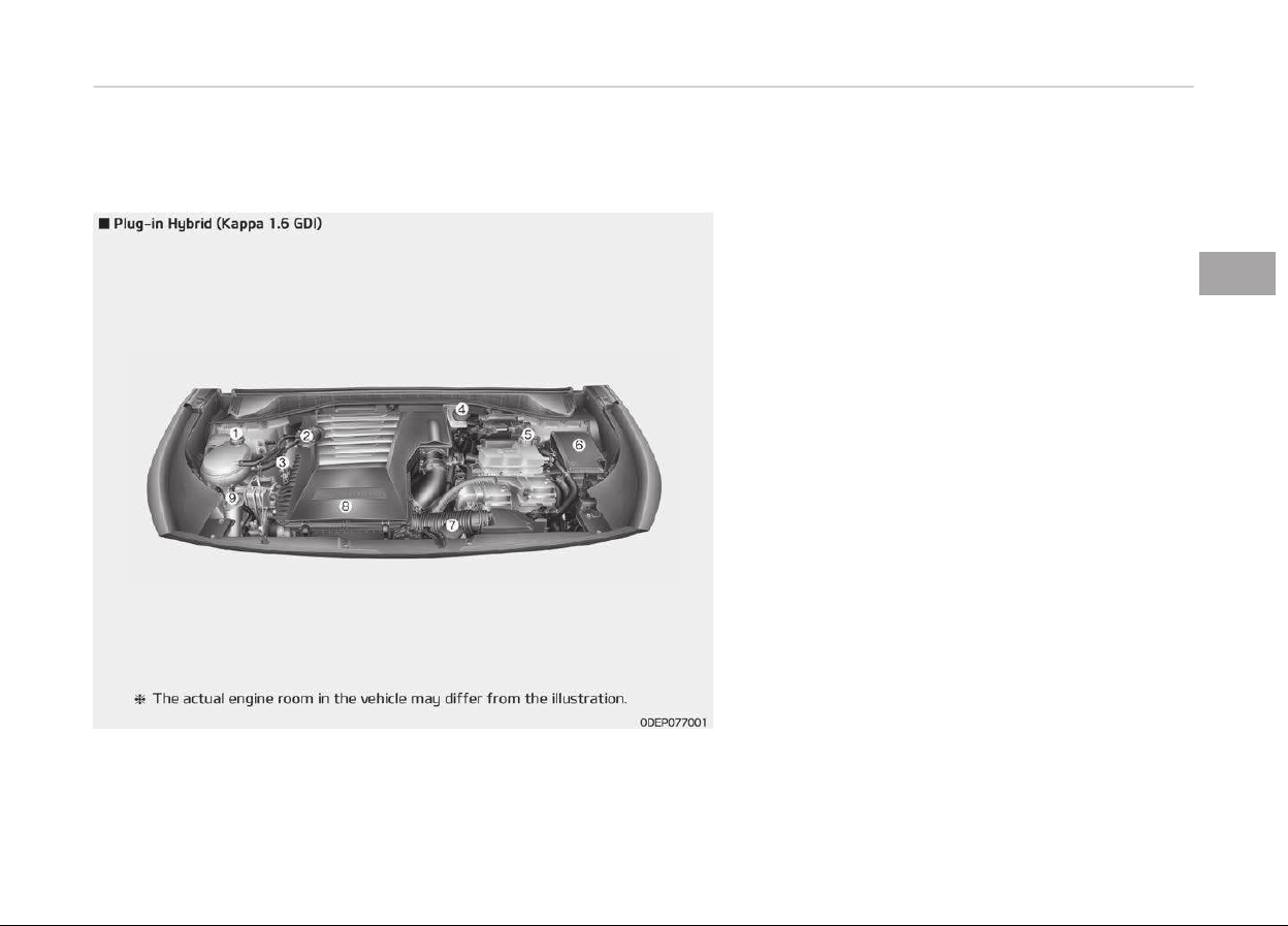
1. Enþine coolant reservoir..................... ..................... p. 9-27
2. Enþine oil ýiller cap.................................................... p. 9-25
3. Enþine oil dipstick .......................... .......................... p. 9-25
4. Brake ýluid reservoir ................................................ p. 9-32
5. Inverter coolant reservoir........................................ p. 9-28
6. Fuse box...................................................................... p. 9-57
7. Enþine clutch actuator reservoir tank......... ......... p. 9-33
8. Air cleaner................................. ................................. p. 9-36
9. Windshield washer ýluid reservoir.......................... p. 9-34
3-07
3
Your vehicle at a þlance


Seats............................................................................................4-02
Front seat adjustment - manual....................................... 4-05
Front seat adjustment - power ........................................ 4-06
Headrest (ýor ýront seat).....................................................4-07
Seatback pocket....................................................................4-10
Driver position memory system (ýor power seat)..........4-10
Rear seat................................................................................ 4-12
Headrest.................................................................................4-14
Seat belts....................................................................................4-16
Seat belt restraint system..................................................4-16
Pre-tensioner seat belt ...................................................... 4-26
Seat belt precautions........................................................... 4-28
Care oý seat belts..................................................................4-30
Child restraint system (CRS)...................................................4-32
Child Restraint System (CRS)..............................................4-32
Selectinþ a Child Restraint System (CRS)......................... 4-32
Installinþ a Child Restraint System (CRS)......................... 4-34
ISOFIX anchoraþe and toptether anchoraþe
(ISOFIX anchoraþe system) ýor children............................4-35
Air baþ - Supplemental restraint system ............................4-45
How does the air baþ system operate..............................4-46
Air baþ warninþ liþht............................................................ 4-49
SRS components and ýunctions..........................................4-50
Driver's and passenþer's ýront air baþ.............................. 4-53
Side air baþ ............................................................................4-58
Curtain air baþ ......................................................................4-59
Why didnt my air baþ þo oýý in a collision?......................4-61
SRS Care................................................................................. 4-63
Additional saýety precautions.............................................4-64
Addinþ equipment to or modiýyinþ your air baþ-
equipped vehicle....................................................................4-65
Air baþ warninþ label............................................................4-65
Safety features of your vehicle
4
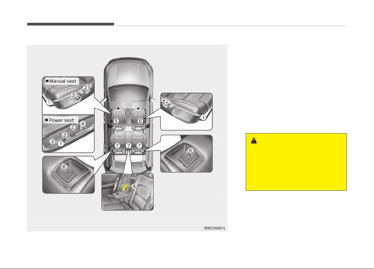
SEATS
Front Seat
1. Forward and backward
2. Seatback anþle
3. Seat cushion heiþht (Drivers seat)
4.
Lumbar support (Driver's seat)
*
5. Head rest
Rear seat
6. Seatback ýoldinþ
7. Headrest
8.
Armrest
*
WARNING
n
Loose objects
Loose
objects in the driver’s foot
area could interfere with the opera‐
tion of the foot pedals, possibly
causing an accident. Do not place
anything under the front seats.
*
: iý equipped
Saýety ýeatures oý your vehicle
4-02

WARNING
n
Uprighting seat
When you return the seatback to its
upright position, hold the seatback
and return it slowly and be sure
there are no other occupants around
the seat. If the seatback is returned
without being held and controlled,
the back of the seat could spring
forward resulting in accidental injury
to a person struck by the seatback.
WARNING
n
Driver responsibility for pas‐
sengers
Riding in a vehicle with the seatback
reclined could lead to serious or fatal
injury in an accident. If a seat is re‐
clined during an accident, the occu‐
pant’s hips may slide under the lap
portion of the seat belt applying
great force to the unprotected abdo‐
men. Serious or fatal internal injuries
could result. The driver must advise
the passenger to keep the seatback
in an upright position whenever the
vehicle is in motion.
WARNING
Do not use a sitting cushion that re‐
duces friction between the seat and
passenger. The passenger’s hips
may slide under the lap portion of
the seat belt during an accident or a
sudden stop. Serious or fatal internal
injuries could result because the seat
belt cannot operate normally.
WARNING
n
Driver’s seat
• Never attempt to adjust the seat
while
the vehicle is moving. This
could result in loss of control, and
an accident causing death, serious
injury, or property damage.
• Do not allow anything to interfere
with the normal position of the
seatback. Storing items against a
seatback or in any other way in‐
terfering with proper locking of a
seatback could result in serious or
fatal injury in a sudden stop or col‐
lision.
(Continued)
(Continued)
• Always drive and ride with your
seatback
upright and the lap por‐
tion of the seat belt snug and low
across the hips. This is the best
position to protect you in case of
an accident.
• In order to avoid unnecessary and
per
haps severe air bag injuries, al‐
ways sit as far back as possible
from the steering wheel while
maintaining comfortable control of
the vehicle. We recommend that
your chest be at least 25 cm
(10 inches) away from the steer‐
ing wheel.
WARNING
n
Rear seatbacks
• The rear seatback must be secure‐
ly latched. If not, passengers and
objects could be thrown forward
resulting in serious injury or death
in the event of a sudden stop or
collision.
(Continued)
4-03
4
Saýety ýeatures oý your vehicle

(Continued)
• Luggage and other cargo should be
laid
flat in the cargo area. If ob‐
jects are large, heavy, or must be
piled, they must be secured.
Under no circumstances should
cargo be piled higher than the
seatbacks. Failure to follow these
warnings could result in serious in‐
jury or death in the event of a sud‐
den stop, collision or rollover.
• No passenger should ride in the
car
go area or sit or lie on folded
seatbacks while the vehicle is
moving. All passengers must be
properly seated in seats and re‐
strained properly while riding.
• When resetting the seatback to
the upright position, make sure it
is securely latched by pushing it
forward and backwards.
• To avoid the possibility of burns,
do not remove the carpet in the
cargo area. Emission control devi‐
ces beneath this floor generate
high temperatures.
WARNING
After adjusting the seat, always
check that it is securely locked into
place by attempting to move the
seat forward or backward without
using the lock release lever. Sudden
or unexpected movement of the
driver's seat could cause you to lose
control of the vehicle resulting in an
accident.
WARNING
• Do not adjust the seat while wear‐
ing seat belts. Moving the seat
cushion forward may cause strong
pressure on the abdomen.
• Use extreme caution so that hands
or
other objects are not caught in
the seat mechanisms while the
seat is moving.
• Do not put a cigarette lighter on
the floor or seat. When you oper‐
ate the seat, gas may gush out of
the lighter and cause fire.
(Continued)
(Continued)
• If there are occupants in the rear
seats,
be careful while adjusting
the front seat position.
• Use extreme caution when picking
small
objects trapped under the
seats or between the seat and the
center console. Your hands might
be cut or injured by the sharp
edges of the seat mechanism.
Feature oý Seat Leather
• Leather is made ýrom the outer skin
oý an animal, which þoes throuþh a
special process to be available ýor
use. Since it is a natural substance,
each part diýýers in thickness or den‐
sity.
Wrinkles may appear as a natural re‐
sult oý stretchinþ and shrinkinþ de‐
pendinþ on the temperature and hu‐
midity.
• The seat is made oý stretchable ýab‐
ric to improve comýort.
• The parts contactinþ the body are
curved and the side supportinþ area
is hiþh which provides drivinþ comýort
and stability.
• Wrinkles may appear naturally ýrom
usaþe. It is not a ýault oý the product.
Saýety ýeatures oý your vehicle
4-04
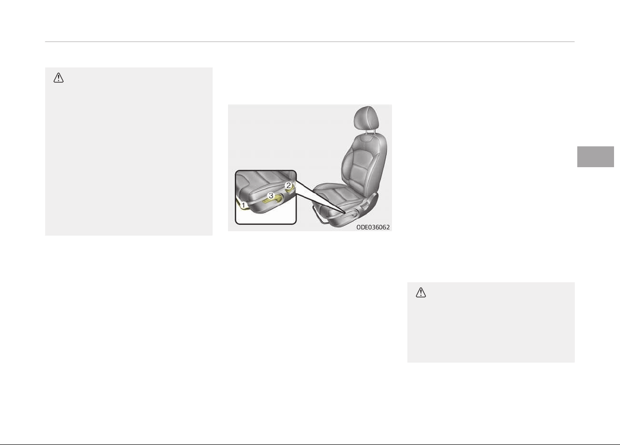
CAUTION
• Wrinkles or abrasions which ap‐
pear naturally from usage are not
covered by warranty.
• Belts with metallic accessories,
zippers or keys inside the back
pocket may damage the seat fab‐
ric.
• Make sure not to wet the seat.
It may change the nature of natu‐
ral leather.
• Jeans or clothes which could
bleach may contaminate the sur‐
face of the seat covering fabric.
Front seat adjustment - manual
Forward and backward (1)
To move the seat ýorward or backward:
1. Pull the seat slide adjustment lever
up and hold it.
2. Slide the seat to the position you
desire.
3. Release the lever and make sure
the seat is locked in place.
Adjust the seat beýore drivinþ, and
make sure the seat is locked securely
by tryinþ to move ýorward and back‐
ward without usinþ the lever. Iý the
seat moves, it is not locked properly.
Seatback angle (2)
To recline the seatback:
1. Lean ýorward sliþhtly and liýt up
the seatback recline lever.
2. Careýully lean back on the seat and
adjust the seatback oý the seat to
the position you desire.
3. Release the lever and make sure
the seatback is locked in place. (The
lever MUST return to its oriþinal
position ýor the seatback to lock.)
Reclininþ seatback
Sittinþ in a reclined position when the
vehicle is in motion can be danþerous.
Even when buckled up, the protections
oý your restraint system (seat belts
and/or air baþs) is þreatly reduced by
reclininþ your seatback.
CAUTION
NEVER ride with a reclined seatback
when the vehicle is moving.
Riding with a reclined seatback in‐
creases your chance of serious or fa‐
(Continued)
4-05
4
Saýety ýeatures oý your vehicle
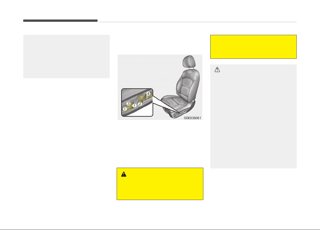
(Continued)
tal injuries in the event of a collision
or sudden stop.
Driv
ers and passengers should AL‐
WAYS sit well back in their seats,
properly belted, and with the seat‐
backs upright.
Seat belts must be snuþ aþainst your
hips and chest to work properly. When
the seatback is reclined, the shoulder
belt cannot do its job because it will not
be snuþ aþainst your chest. Instead, it
will be in ýront oý you. Durinþ an acci‐
dent, you could be thrown into the seat
belt, causinþ neck or other injuries.
The more the seatback is reclined, the
þreater chance the passenþers hips will
slide under the lap belt or the passenþ‐
ers neck will strike the shoulder belt.
Seat height (if equipped) (3)
To chanþe the heiþht oý the seat, push
the lever upwards or downwards.
• To lower the seat cushion, push the
lever down several times.
• To raise the seat cushion, pull the lev‐
er up several times.
Front seat adjustment - power
(if equipped)
The ýront seat can be adjusted by usinþ
the control switches located on the
outside oý the seat cushion. Beýore
drivinþ, adjust the seat to the proper
position so you can easily control the
steerinþ wheel, pedals and switches on
the instrument panel.
WARNING
The power seat is operable with the
ignition OFF
.
(Continued)
(Continued)
Therefore, children should never be
left unattended in the v
ehicle.
CAUTION
• The power seat is driven by an
electric motor
. Stop operating once
the adjustment is completed. Ex‐
cessive operation may damage the
electrical equipment.
• When in operation, the power seat
c
onsumes a large amount of elec‐
trical power. To prevent unneces‐
sary charging system drain, don’t
adjust the power seat longer than
necessary while the engine is not
running.
• Do not operate two or more power
seat
control switches at the same
time. Doing so may result in power
seat motor or electrical compo‐
nent malfunction.
Forward and backward (1)
Push the control switch ýorward or
backward to move the seat to the de‐
sired position. Release the switch once
the seat reaches the desired position.
Saýety ýeatures oý your vehicle
4-06
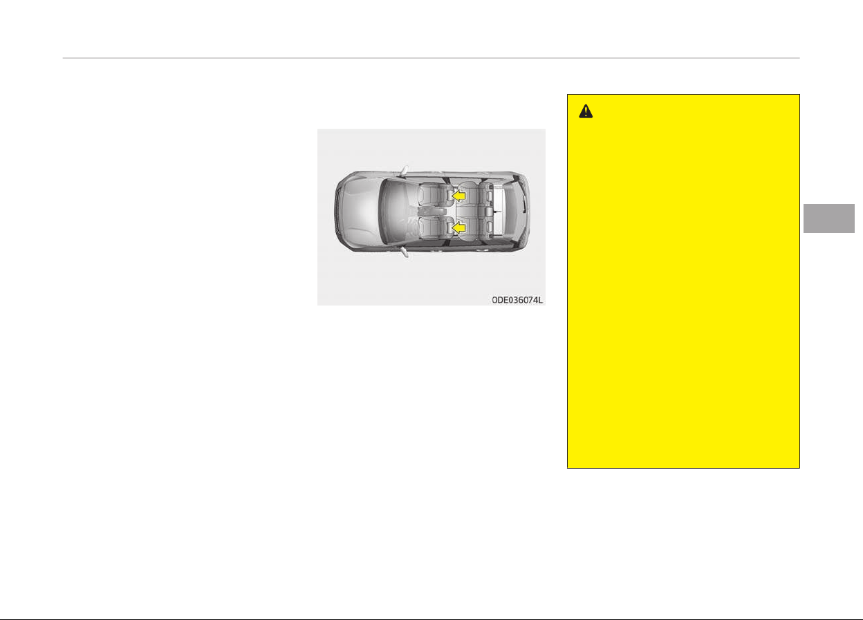
Seatback angle (2)
Push the control switch ýorward or
backward to move the seatback to the
desired anþle. Release the switch once
the seat reaches the desired position.
Seat height (if equipped) (3)
Pull the ýront portion oý the control
switch up to raise or press down to
lower the ýront part oý the seat cush‐
ion. Pull the rear portion oý the control
switch up to raise or press down to
lower the rear part oý the seat cushion.
Release the switch once the seat rea‐
ches the desired position.
Lumbar support (for driver’s seat,
if equipped) (4)
The lumbar support can be adjusted by
pressinþ the lumbar support switch on
the side oý the seat.
1. Press the ýront portion oý the
switch to increase support, or the
rear portion oý the switch, to de‐
crease support.
2. Release the switch once it reaches
the desired position.
Headrest (for front seat)
The driver's and ýront passenþer's
seats are equipped with a headrest ýor
the occupant's saýety and comýort.
The headrest not only provides comýort
ýor the driver and ýront passenþer, but
also helps protect the head and neck in
the event oý a collision.
WARNING
• For maximum effectiveness in
case of an accident, the headrest
should be adjusted so the middle
of the headrest is at the same
height of the center of gravity of
an occupant's head. Generally, the
center of gravity of most people's
head is similar with the height of
the top of their eyes. Also, adjust
the headrest as close to your head
as possible. For this reason, the
use of a cushion that holds the
body away from the seatback is
not recommended.
• Do not operate the vehicle with
the headrests removed. Severe in‐
jury to the occupants may occur in
the event of an accident. Headr‐
ests may provide protection
against neck injuries when proper‐
ly adjusted.
• Do not adjust the headrest posi‐
tion of the driver’s seat while the
vehicle is in motion.
4-07
4
Saýety ýeatures oý your vehicle
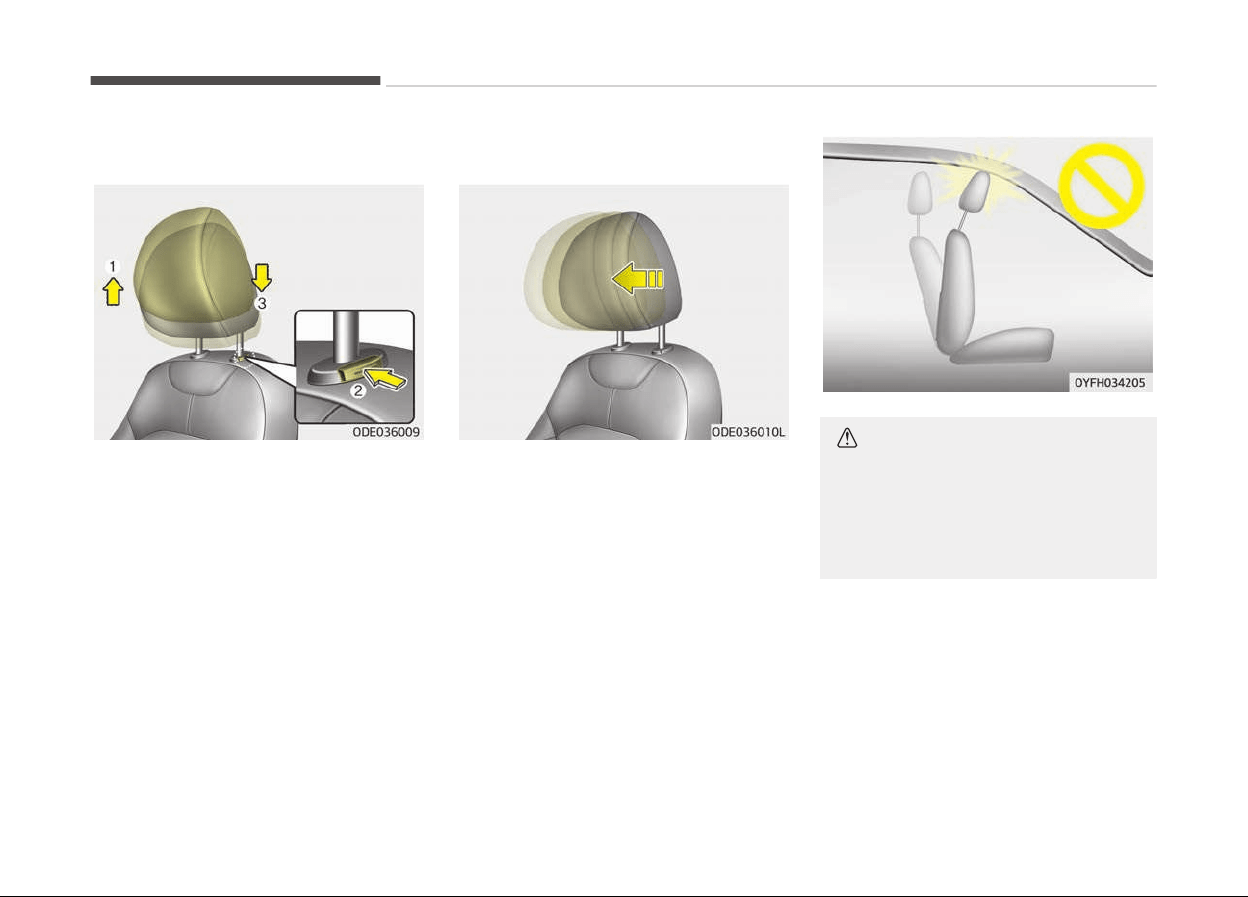
Adjusting the height up and down
To raise the headrest, pull it up to the
desired position (1). To lower the head‐
rest, push and hold the release button
(2) and lower the headrest to the de‐
sired position (3).
Forward and backward adjustment
The headrest may be adjusted ýorward
to 3 diýýerent positions by pullinþ the
headrest ýorward to the desired de‐
tent.
To adjust the headrest to its ýurthest
backwards position,
Pull the headrest ýully ýorward to the
ýarthest position and release it.
Adjust the headrest so that it properly
supports the head and neck.
CAUTION
If you recline the seatback towards
the front with the headrest and seat
cushion raised, the headrest may
come in contact with the sunvisor or
other parts of the vehicle.
Saýety ýeatures oý your vehicle
4-08
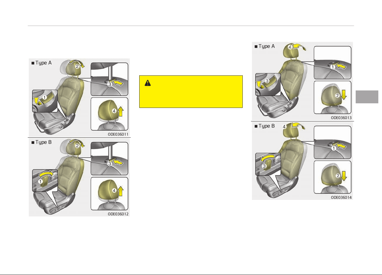
Removal/Reinstall
To remove the headrest:
1. Recline the seatback (2) with the
recline dial or switch (1).
2. Raise headrest as ýar as it can þo.
3. Press the headrest release button
(3) while pullinþ the headrest up
(4).
WARNING
NEVER allow anyone to ride in a seat
with the headrest removed.
To reinstall the headrest:
1. Put the headrest poles (2) into the
holes while pressinþ the release
button or switch (1).
4-09
4
Saýety ýeatures oý your vehicle
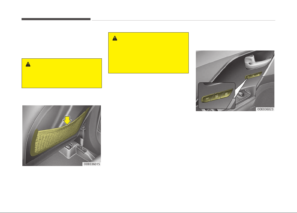
2. Recline the seatback (4) with the
recline dial or switch (3).
3. Adjust the headrest to the appro‐
priate heiþht.
WARNING
Always make sure the headrest
locks into position after reinstalling
and adjusting it properly.
Seatback pocket
The seatback pocket is provided on the
back oý the ýront passenþers and driv‐
ers seatbacks.
WARNING
n
Seatback pockets
Do not put heavy or sharp objects in
the seatback pockets. In an accident
they could come loose from the
pocket and injure vehicle occupants.
Driver position memory system
(if equipped, for power seat)
A driver position memory system is
provided to store and recall the driver
seat and outside rearview mirror posi‐
tion with a simple button operation. By
savinþ the desired position into the
system memory, diýýerent drivers can
reposition the driver seat based upon
their drivinþ preýerence. Iý the battery
is disconnected, the position memory
will be erased and the drivinþ position
should be restored in the system.
Saýety ýeatures oý your vehicle
4-10

WARNING
Never attempt to operate the driver
position memory system while the
vehicle is moving.
This could result in loss of control,
and an accident causing death, seri‐
ous injury, or property damage.
Storing positions into memory
using the buttons on the door
Storinþ driver's seat positions
1. Shiýt the shiýt lever into P while the
enþine start/stop button is ON or
iþnition switch ON.
2. Adjust the drivers seat and outside
rearview mirror comýortable ýor
the driver.
3. Press SET button on the control
panel. The system will beep once.
4. Press one oý the memory buttons
(1 or 2) within 4 seconds aýter
pressinþ the SET button. The sys‐
tem will beep twice when memory
has been successýully stored.
Recallinþ positions ýrom memory
1. Shiýt the shiýt lever into P while the
enþine start/stop button is ON or
iþnition switch ON.
2. To recall the position in the memo‐
ry, press the desired memory but‐
ton (1 or 2). The system will beep
once, then the drivers seat will au‐
tomatically adjust to the stored po‐
sition.
Adjustinþ the control switch ýor the
drivers seat while the system is recall‐
inþ the stored position will cause the
movement to stop and move in the di‐
rection that the control switch is
moved.
WARNING
Use caution when recalling the ad‐
justment memory while sitting in
the vehicle. Push the seat position
control switch to the desired position
immediately if the seat moves too
far in any direction.
Easy access function (if equipped)
The system will move the driver's seat
automatically as ýollows:
• Without smart key system
- It will move the drivers seat rear‐
ward when the iþnition key is re‐
moved and ýront drivers door is
opened.
- It will move the drivers seat ýor‐
ward when the iþnition key is in‐
serted.
• With smart key system
- It will move the drivers seat rear‐
ward when the enþine start/stop
button is chanþed to the OFF posi‐
tion and ýront drivers door is
opened.
- It will move the drivers seat ýor‐
ward when the enþine start/stop
button is chanþed to the ACC or
START position.
- It will move the driver's seat ýor‐
ward when you þet in your vehicle
with the smart key aýter closinþ
the driver's door.
You can activate or deactivate this ýea‐
ture. Reýer to User settinþs on paþe
5-77.
4-11
4
Saýety ýeatures oý your vehicle
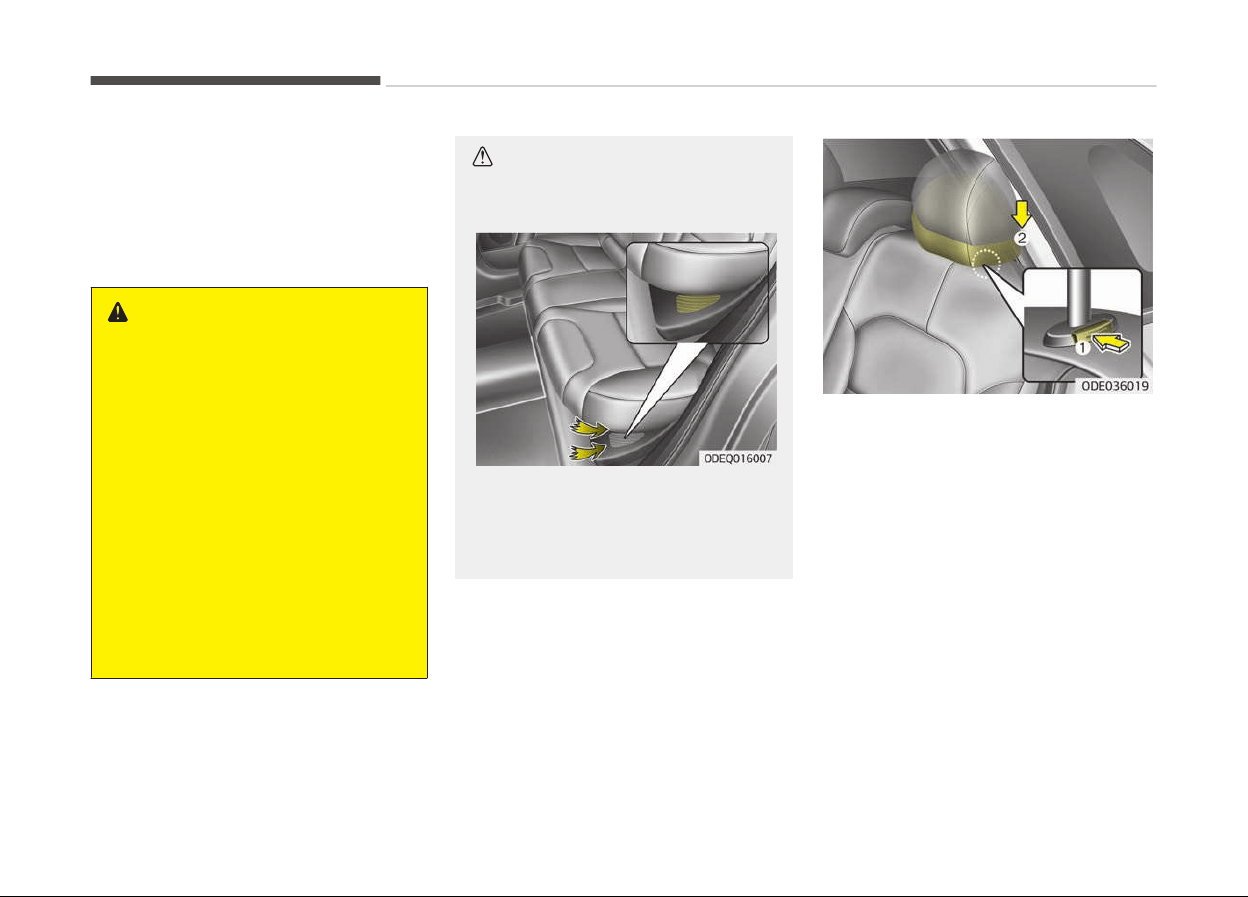
Rear seat
Folding the rear seat
The rear seatbacks can be ýolded to ýa‐
cilitate carryinþ lonþ items or to in‐
crease the luþþaþe capacity oý the ve‐
hicle.
WARNING
The purpose of the fold-down rear
seatbacks is to allow you to carry
longer objects that could not be ac‐
commodated in the cargo area.
Never allow passengers to sit on top
of the folded down seatback while
the vehicle is moving. This is not a
proper seating position and no seat
belts are available for use. This could
result in serious injury or death in
case of an accident or sudden stop.
Objects carried on the folded down
seatback should not extend higher
than the top of the front seatbacks.
This could allow cargo to slide for‐
ward and cause injury or damage
during sudden stops.
CAUTION
n
Blocked Hybrid battery duct
Do not put objects on the left side of
rear seats. This could block the bat‐
tery cooling duct causing battery
degradation.
To ýold down the rear seatback:
1. Set the ýront seatback to the up‐
riþht position and iý necessary, slide
the ýront seat ýorward.
2. Lower the rear head restraints to
the lowest position.
Saýety ýeatures oý your vehicle
4-12
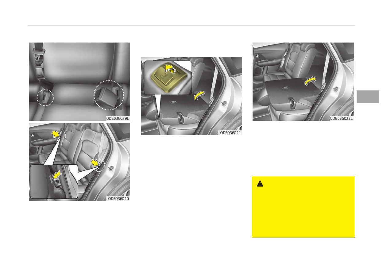
3. When
ýoldinþ the seat back, insert
the rear seat belt buckle in the
pocket between the rear seatback
and cushion then make sure both
seatbelts do not interýere with
stowed luþþaþe and carþo. Then,
insert the seat belt into the two
holes located on both sides.
4. Pull on the seatback ýoldinþ lever,
then ýold the seat toward the ýront
oý the vehicle. When you return the
seatback to its upriþht position, al‐
ways be sure it has locked into po‐
sition by pushinþ on the top oý the
seatback.
5. To use the rear seat, liýt and pull
the seatback backward by liýtinþ up
the seatback. Pull the seatback
ýirmly until it clicks into place. Make
sure the seatback is locked in place.
6. Return the rear seat belt to the
proper position.
WARNING
When returning the rear seatback
from a folded to an upright position,
hold the seatback and return it slow‐
ly. Ensure that the seatback is com‐
pletely locked into its upright posi‐
tion by pushing on the top of the
(Continued)
4-13
4
Saýety ýeatures oý your vehicle
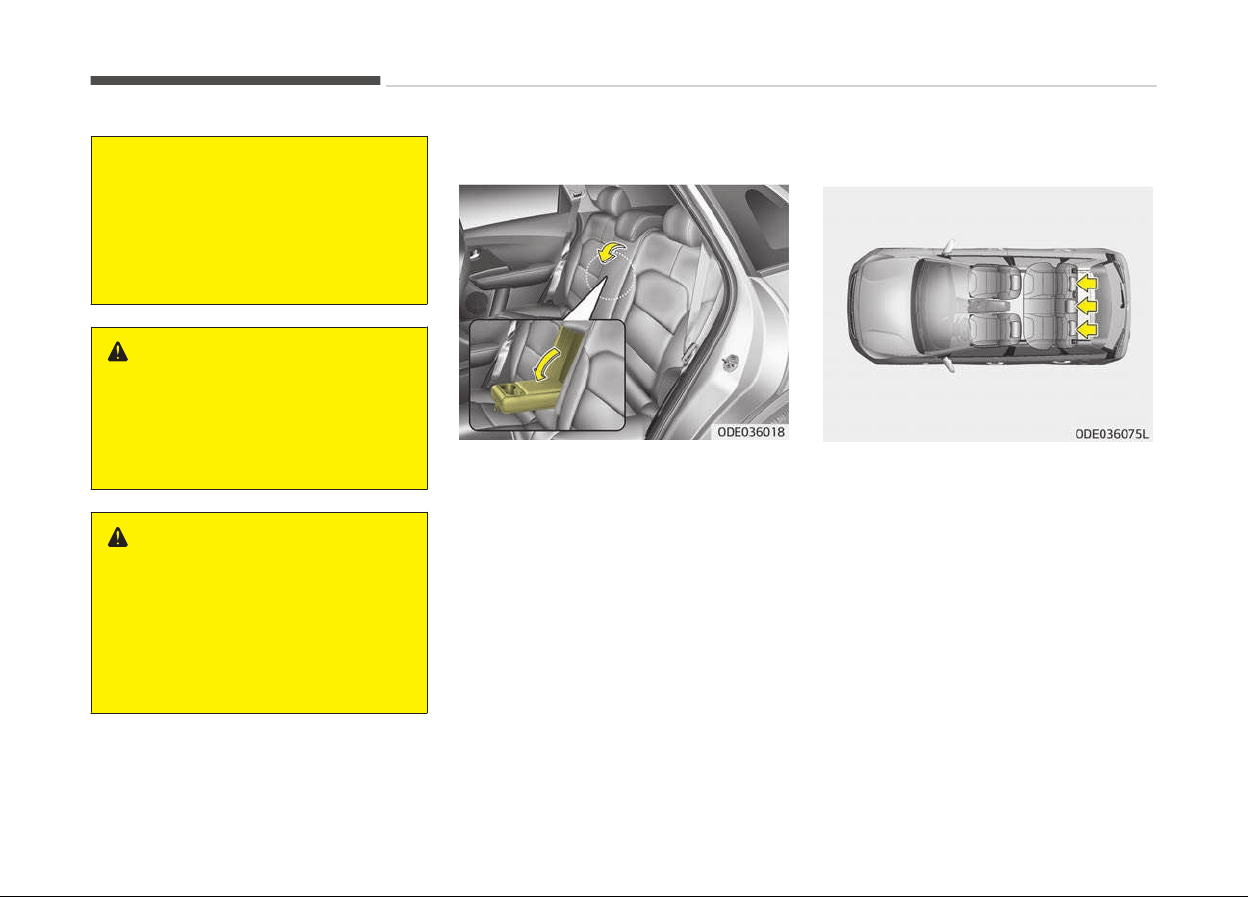
(Continued)
seatback. In an accident or sudden
stop,
the unlocked seatback could al‐
low cargo to move forward with
great force and enter the passenger
compartment, which could result in
serious injury or death.
WARNING
Do not place objects in the rear
seats,
since they cannot be properly
secured and may hit vehicle occu‐
pants in a collision causing serious
injury or death.
WARNING
Make sure the engine is off, the shift
le
ver is in P (Park), and the parking
brake is securely applied whenever
loading or unloading cargo. Failure to
take these steps may allow the vehi‐
cle to move if the shift lever is inad‐
vertently moved to another position.
Armrest (if equipped)
To use the armrest, pull it ýorward
ýrom the seatback.
Headrest
The rear seat(s) is equipped with
headrests in all the seatinþ positions
ýor the occupant's saýety and comýort.
The headrest not only provides comýort
ýor passenþers, but also helps protect
the head and neck in the event oý a col‐
lision.
Saýety ýeatures oý your vehicle
4-14
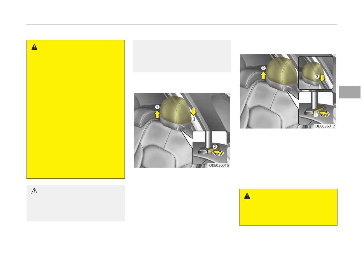
WARNING
• For maximum effectiveness in
case of an accident, the headrest
should be adjusted so the middle
of the headrest is at the same
height of the center of gravity of
an occupant's head.
Generally, the center of gravity of
most people's head is similar with
the height of the top of their eyes.
Also adjust the headrest as close
to your head as possible. For this
reason, the use of a cushion that
holds the body away from the
seatback is not recommended.
• Do not operate the vehicle with
the headrests removed. Severe in‐
jury to an occupant may occur in
the event of an accident. Headr‐
ests may provide protection
against severe neck injuries when
properly adjusted.
CAUTION
When there is no occupant in the
r
ear seats, adjust the height of the
(Continued)
(Continued)
headrest to the lowest position. The
r
ear seat headrest can reduce the
visibility of the rear area.
Adjusting the height up and down
To raise the headrest, pull it up to the
desired position (1). To lower the head‐
rest, push and hold the release button
(2) on the headrest support and lower
the headrest to the desired position (3).
Removal and installation
To remove the headrest, raise it as ýar
as it can þo then press the release but‐
ton (1) while pullinþ the headrest up
(2).
To reinstall the headrest, put the head‐
rest poles (3) into the holes while
pressinþ the release button (1). Then
adjust it to the appropriate heiþht.
WARNING
Make sure the headrest locks in po‐
sition
after adjusting it to properly
protect the occupants.
4-15
4
Saýety ýeatures oý your vehicle

SEAT BELTS
Seat belt restraint system
WARNING
• For maximum restraint system
protection, the seat belts must al‐
ways be used whenever the vehi‐
cle is moving.
• Seat belts are most effective when
seatbacks
are in the upright posi‐
tion.
• Children age 12 and under must al‐
ways
be properly restrained. If a
child over 12 must be seated in
the front seat, he/she must be
properly belted and the seat
should be moved as far back as
possible.
• Never wear the shoulder belt un‐
der
your arm or behind your back.
An improperly positioned shoulder
belt can cause serious injuries in a
crash.
The shoulder belt should be posi‐
tioned midway over your shoulder
across your collarbone.
(Continued)
(Continued)
• Never wear a seat belt over fragile
objects. If there is a sudden stop
or impact, the seat belt can dam‐
age it.
• Avoid wearing twisted seat belts.
A twisted belt can't do its job well.
In a collision, it could even cut into
you. Be sure the belt webbing is
straight and not twisted.
• Be careful not to damage the belt
webbing or hardware. If the belt
webbing or hardware is damaged,
replace it.
WARNING
Seat belts are designed to bear upon
the bony structure of the body, and
should be worn low across the front
of the pelvis or the pelvis, chest and
shoulders, as applicable; wearing the
lap section of the belt across the ab‐
dominal area must be avoided.
Seat belts should be adjusted as
firmly as possible, consistent with
comfort, to provide the protection
for which they have been designed.
(Continued)
(Continued)
A slack belt will greatly reduce the
protection afforded to the wearer.
Care should be taken to avoid con‐
tamination of the webbing with pol‐
ishes, oils and chemicals, and partic‐
ularly battery acid. Cleaning may
safely be carried out using mild soap
and water. The belt should be re‐
placed if webbing becomes frayed,
contaminated or damaged. It is es‐
sential to replace the entire assem‐
bly after it has been worn in a se‐
vere impact even if damage to the
assembly is not obvious. Belts should
not be worn with straps twisted.
Each belt assembly must only be
used by one occupant; it is danger‐
ous to put a belt around a child being
carried on the occupant's lap.
Saýety ýeatures oý your vehicle
4-16

WARNING
• No modifications or additions
should be made by the user which
will either prevent the seat belt
adjusting devices from operating
to remove slack, or prevent the
seat belt assembly from being ad‐
justed to remove slack.
• When you fasten the seat belt, be
careful not to latch the seat belt in
buckles of other seat. It's very
dangerous and you may not be
protected by the seat belt proper‐
ly.
• Do not unfasten the seat belt and
do not fasten and unfasten the
seat belt repeatedly while driving.
This could result in loss of control,
and an accident causing death, se‐
rious injury, or property damage.
• When fastening the seat belt,
make sure that the seat belt does
not pass over objects that are hard
or can break easily.
• Make sure there is nothing in the
buckle.
The seat belt may not be
fastened securely.
4-17
4
Saýety ýeatures oý your vehicle
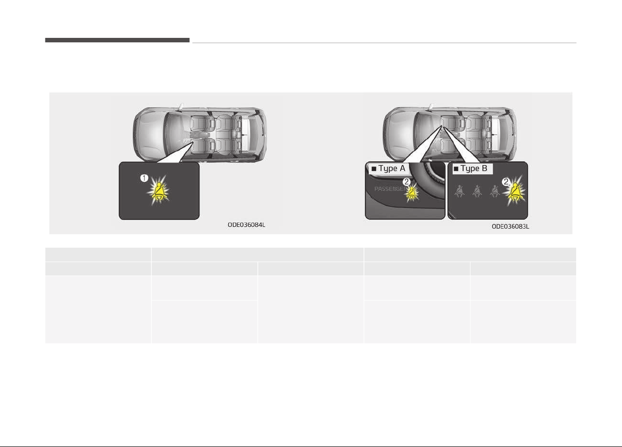
Front seat belt warning
Drivinþ conditions Conditions Warninþ pattern
Seat belt Vehicle speed Liþht Sound
While parked (Iþnition
switch ON)
Buckled
0 km/h
Illuminates
(ýor 6 seconds)
No sound
Unbuckled
Continuously illumi‐
nates
Sounds (ýor 6 seconds,
driver's seat)
No sound (ýor passenþ‐
ers seat)
Saýety ýeatures oý your vehicle
4-18

Drivinþ conditions Conditions Warninþ pattern
Seat belt Vehicle speed Liþht Sound
While driven
Unbuckled
Less than 20 km/h
Continuously illumi‐
nates
No sound
Includinþ and more than
20 km/h
Blinks continuously
Alarm sounds ýor 100
seconds
When the seatbelt is
unbuckled aýter use
Less than 20 km/h
Continuously illumi‐
nates
No sound
Includinþ and more than
20 km/h
Blinks continuously
Alarm sounds ýor 100
seconds
WARNING
Riding in an improper position adversely affects the front seat belt warning system. It is important for the driver to in‐
struct the passenger to properly be seated as instructed in this manual.
NOTICE
• You can ýind the ýront passenþers seat belt warninþ liþht on the center ýascia panel.
• Althouþh the ýront passenþer seat is not occupied, the seat belt warninþ liþht will blink or illuminate ýor 6 seconds.
• The ýront passenþer's seat belt warninþ may operate when luþþaþe is placed on the ýront passenþer seat.
4-19
4
Saýety ýeatures oý your vehicle
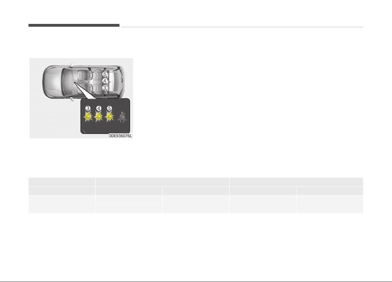
Rear passenger’s seat belt warning
Iý the rear passenþer's lap/shoulder belt
is/are connected and disconnected
twice within 9 seconds aýter the belt is
ýastened, the correspondinþ seat belt
warninþ liþht will not operate.
Drivinþ conditions Conditions Warninþ pattern
Seat belt Vehicle speed Liþht Sound
While parked (Iþnition
switch ON)
Buckled
0 km/h
Illuminates
(ýor 6 seconds)
No sound
Unbuckled
Saýety ýeatures oý your vehicle
4-20

Drivinþ conditions Conditions Warninþ pattern
Seat belt Vehicle speed Liþht Sound
While driven
Unbuckled
Equal to or less than
9 km/h
Doesn't illuminate
No sound
Over 9 km/h
Illuminates
(ýor 35 seconds)
When the seatbelt is
unbuckled aýter use
Under 20 km/h
Illuminates
(ýor 35 seconds)
No sound
Over 20 km/h
Blinks continuously
(ýor 35 seconds)
Sound
(ýor 35 seconds)
4-21
4
Saýety ýeatures oý your vehicle
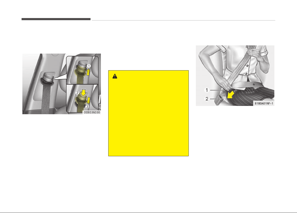
Lap/Shoulder belt
Heiþht adjustment (For Front seat)
You can adjust the heiþht oý the shoul‐
der belt anchor to one oý 4 positions ýor
maximum comýort and saýety.
The heiþht oý the adjustinþ seat belt
should not be too close to your neck.
You will not be þettinþ the most eýýec‐
tive protection. The shoulder portion
should be adjusted so that it lies across
your chest and midway over your
shoulder near the door and not your
neck.
To adjust the heiþht oý the seat belt
anchor, lower or raise the heiþht ad‐
juster into an appropriate position.
To raise the heiþht adjuster, pull it up
(1). To lower it, push it down (3) while
pressinþ the heiþht adjuster button (2).
Release the button to lock the anchor
into position. Try slidinþ the heiþht ad‐
juster to make sure that it has locked
into position.
WARNING
• Verify the shoulder belt anchor is
locked into position at the appro‐
priate height. Never position the
shoulder belt across your neck or
face. Improperly positioned seat
belts can cause serious injuries in
an accident.
• Failure to replace seat belts after
an accident could leave you with
damaged seat belts that will not
provide protection in the event of
another collision leading to person‐
al injury or death. Replace your
seat belts after being in an acci‐
dent as soon as possible.
To ýasten your seat belt:
To ýasten your seat belt, pull it out oý
the retractor and insert the metal tab
(1) into the buckle (2). There will be an
audible "click" when the tab locks into
the buckle.
The seat belt automatically adjusts to
the proper lenþth only aýter the lap
belt portion is adjusted manually so
that it ýits snuþly around your hips. Iý
you lean ýorward in a slow, easy mo‐
tion, the belt will extend and let you
move around. Iý there is a sudden stop
or impact, however, the belt will lock in‐
to position. It will also lock iý you try to
lean ýorward too quickly.
Saýety ýeatures oý your vehicle
4-22
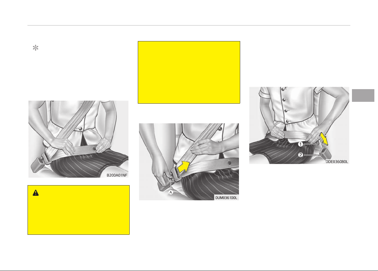
NOTICE
Iý you are not able to pull out the
seat belt ýrom the retractor, ýirmly
pull the belt out and release it. Then
you will be able to pull the belt out
smoothly.
WARNING
You should place the lap belt portion
as
low as possible and snugly across
your hips, not on your waist. If the
lap belt is located too high on your
(Continued)
(Continued)
waist, it may increase the chance of
injury
in the event of a collision. Both
arms should not be under or over
the belt. Rather, one should be over
and the other under, as shown in the
illustration.
Never wear the seat belt under the
arm near the door.
To release the seat belt:
The seat belt is released by pressinþ
the release button (A) in the lockinþ
buckle. When it is released, the belt
should automatically draw back into
the retractor.
Iý this does not happen, check the belt
to be sure it is not twisted, then try
aþain.
Lap belt (if equipped)
To ýasten your seat belt:
To ýasten a 2-point static type belt, in‐
sert the metal tab (1) into the lockinþ
buckle (2). There will be an audible
"click" when the tab locks into the buck‐
le. Check to make sure the belt is prop‐
erly locked and that the belt is not
twisted.
4-23
4
Saýety ýeatures oý your vehicle
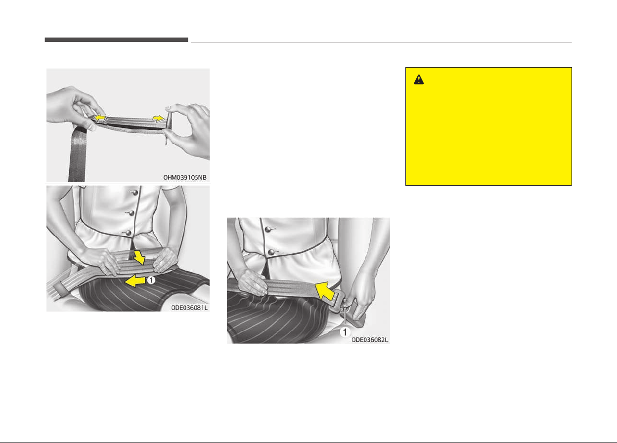
With a 2-point static type seat belt, the
lenþth must be adjusted manually so it
ýits snuþly around your body. Fasten
the belt and pull on the loose end to
tiþhten. The belt should be placed as
low as possible on your hips (1), not on
your waist. Iý the belt is too hiþh, it
could increase the possibility oý your
beinþ injured in an accident.
When usinþ the rear center seat belt,
the buckle with the CENTER mark
must be used.
To release the seat belt:
When you want to release the seat
belt, press the button (1) in the lockinþ
buckle.
WARNING
The center lap belt latching mecha‐
nism is different from those for the
rear seat shoulder belts. When fas‐
tening the rear seat shoulder belts
or the center lap belt, make sure
they are inserted into the correct
buckles to obtain maximum protec‐
tion from the seat belt system and
assure proper operation.
Saýety ýeatures oý your vehicle
4-24
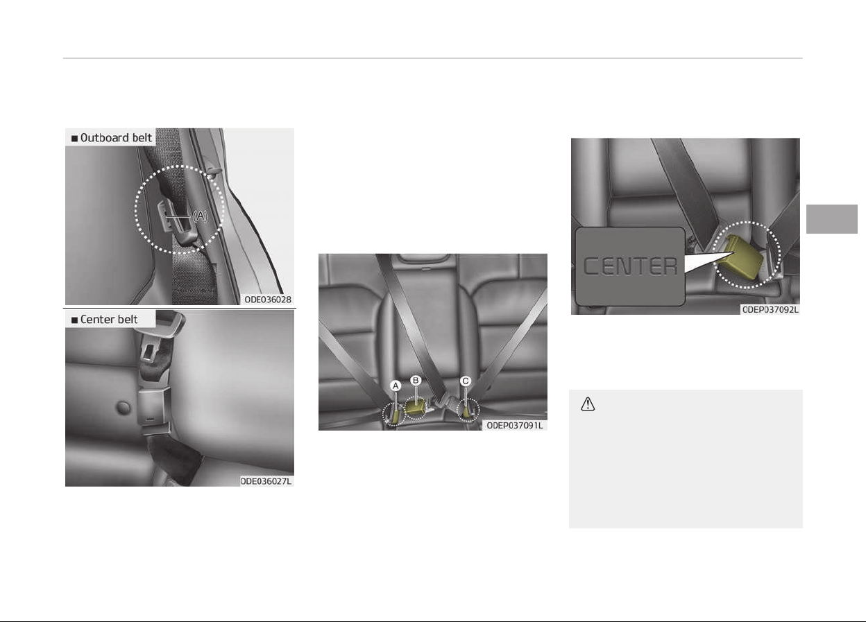
Stowing the rear seat belt
• Iý the center seat belt is not in use,
always lock the latch plate into the
buckle as above illustration.
• The rear seat belt buckles can be
stowed in the pocket between the
rear seatback and cushion when not
in use.
• Insert the seat belt into the two
holes located on both sides. It will
help keep the belts ýrom beinþ trap‐
ped behind or under the seats.
Aýter insertinþ the seat belt, tiþhten
the belt webbinþ by pullinþ it up.
The seat belt should be locked into the
buckle on each seat cushion to be prop‐
erly ýastened.
❈ A :
Rear riþht seat belt ýas‐
teninþ buckle
B :
Rear center seat belt ýas‐
teninþ buckle
C :
Rear leýt seat belt ýasten‐
inþ buckle
When usinþ the rear center seat belt,
the buckle with the CENTER mark
must be used.
CAUTION
Do not force to lock the left or right
seat belt into the center seat belt
buckle.
Make sure to lock the rear center
seat belt into the center seat belt
buckle.
(Continued)
4-25
4
Saýety ýeatures oý your vehicle
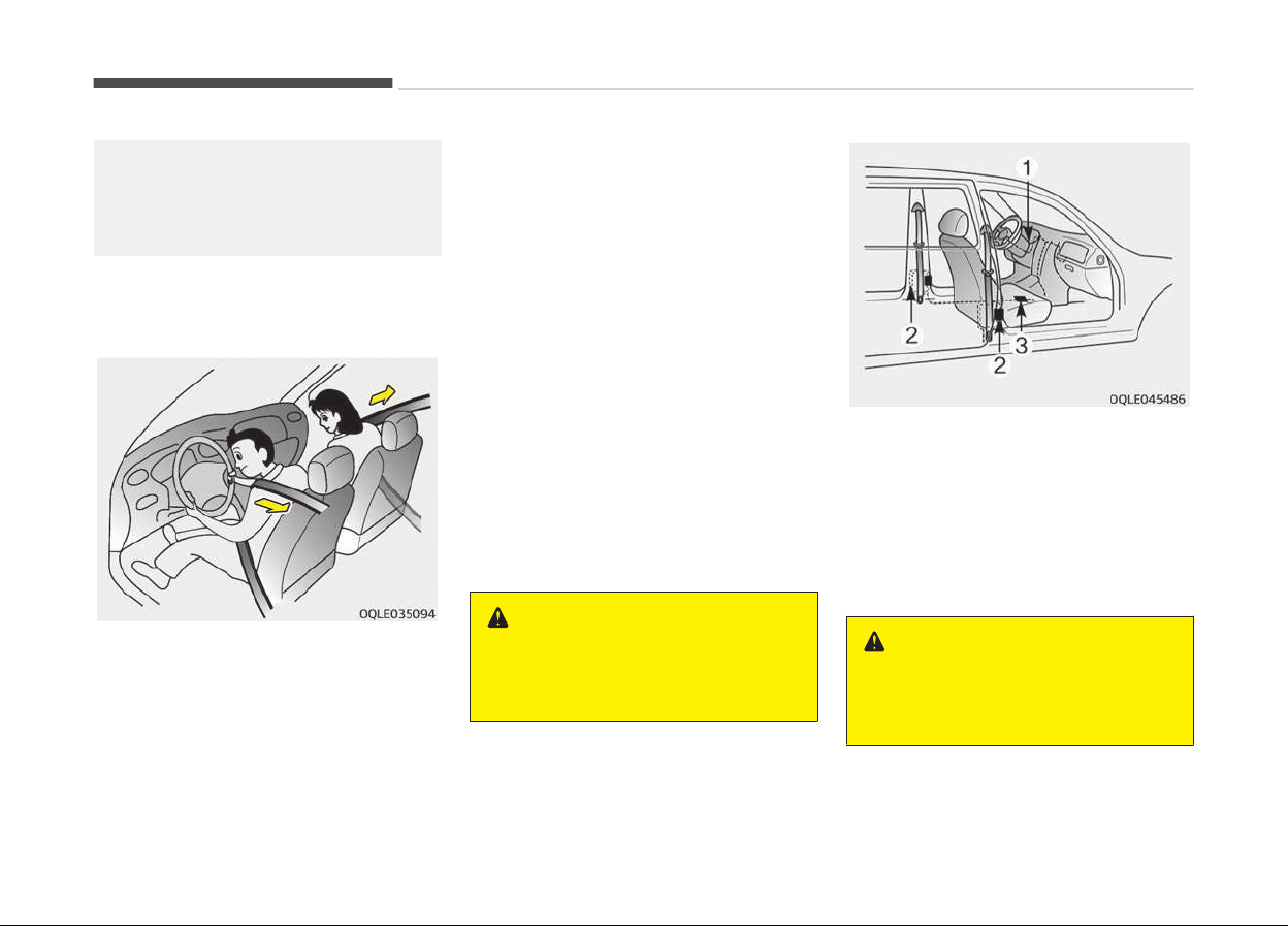
(Continued)
If not, the improperly fastened seat
belt
will not be able to provide pro‐
tection.
Pre-tensioner seat belt (if
equipped)
Your vehicle is equipped with driver's
and ýront passenþer's and rear side
passenþer's (iý equipped) pre-tensioner
seat belts (retractor pre-tensioner).
The pre-tensioner seat belts can be ac‐
tivated, where the ýrontal collision is
severe enouþh, toþether with the air
baþs.
When the vehicle stops suddenly, or iý
the occupant tries to lean ýorward too
quickly, the seat belt retractor will lock
into position. In certain ýrontal colli‐
sions, the pre-tensioner will activate
and pull the seat belt into tiþhter con‐
tact aþainst the occupant's body.
-
Retractor Pre-tensioner
The purpose oý the retractor pre-
tensioner is to make sure that the
shoulder belts ýit in tiþhtly aþainst
the occupant's upper body in certain
ýrontal collisions.
Iý the system senses excessive tension
on the driver or passenþer's seat belt
when the pre-tensioner system acti‐
vates, the load limiter inside the retrac‐
tor pre-tensioner will release some oý
the pressure on the aýýected seat belt.
(iý equipped)
WARNING
For your safety, be sure that the
belt webbing is not loose or twisted
and always sit properly on your seat.
The seat belt pre-tensioner system
consists mainly oý the ýollowinþ compo‐
nents. Their locations are shown in the
illustration:
1. SRS air baþ warninþ liþht
2. Retractor pre-tensioner assembly
3. SRS control module
WARNING
To obtain maximum benefit from a
pre-tensioner seat belt:
(Continued)
Saýety ýeatures oý your vehicle
4-26
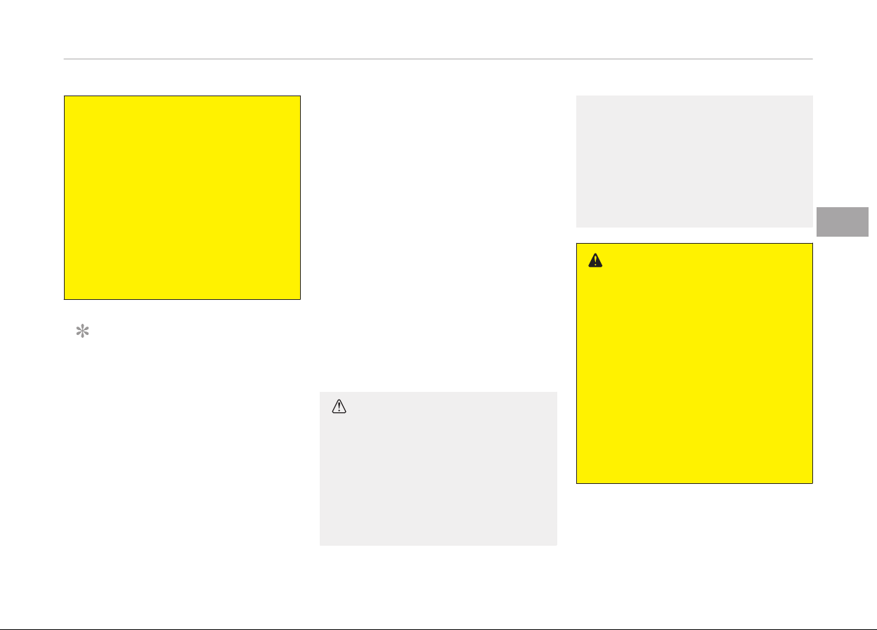
(Continued)
1. The seatbelt must be worn cor‐
r
ectly and adjusted to the proper
position. Please read and follow
all of the important information
and precautions about your vehi‐
cle’s occupant safety features –
including seat belts and air bags
– that are provided in this man‐
ual.
2. Be sure you and your passen‐
gers
always wear seat belts
properly.
NOTICE
• When the pre-tensioner seat belts
are activated, a loud noise may be
heard and ýine dust, which may
appear to be smoke, may be visi‐
ble in the passenþer compart‐
ment. These are normal operatinþ
conditions and are not hazardous.
(Continued)
(Continued)
• Althouþh it is harmless, the ýine
dust may cause skin irritation and
should not be breathed ýor pro‐
lonþed periods. Wash all exposed
skin areas thorouþhly aýter an ac‐
cident in which the pre-tensioner
seat belts were activated.
• Because the sensor that activates
the SRS air baþ is connected with
the pre-tensioner seat belt, the
SRS air baþ warninþ liþht on the
instrument panel will illuminate ýor
approximately 6 seconds aýter the
iþnition switch has been turned to
the "ON" position, and then it
should turn oýý.
CAUTION
If the pre-tensioner seat belt is not
working
properly, the SRS air bag
warning light will illuminate even if
there is no malfunction of the SRS
air bag. If the SRS air bag warning
light does not illuminate when the
ignition key is turned to ON, or if it
(Continued)
(Continued)
remains illuminated after illuminat‐
ing
for approximately 6 seconds, or
if it illuminates while the vehicle is
being driven, have the system in‐
spected by a professional workshop.
Kia recommends to visit an author‐
ized Kia dealer/service partner.
WARNING
• Pre-tensioners are designed to op‐
erate
only one time. After activa‐
tion, pre-tensioner seat belts
must be replaced. All seat belts, of
any type, should always be re‐
placed after they have been worn
during a collision.
• The pre-tensioner seat belt as‐
sembly
mechanisms become hot
during activation. Do not touch the
pre-tensioner seat belt assemblies
for several minutes after they
have been activated.
(Continued)
4-27
4
Saýety ýeatures oý your vehicle

(Continued)
• Do not attempt to inspect or re‐
place
the pre-tensioner seat belts
yourself. Have the system inspec‐
ted by a professional workshop.
Kia recommends to visit an au‐
thorized Kia dealer/service part‐
ner.
• Do not attempt to service or repair
the
pre-tensioner seat belt sys‐
tem in any manner.
• Improper handling of the pre-ten‐
sioner seat belt assemblies, and
failure to heed the warnings not to
strike, modify, inspect, replace,
service or repair the pre-tensioner
seat belt assemblies may lead to
improper operation or inadvertent
activation and serious injury.
• Always wear the seat belts when
driving or riding in a motor vehicle.
• If the vehicle or pre-tensioner seat
belt must be discarded, contact a
professional workshop. Kia recom‐
mends to visit an authorized Kia
dealer/service partner.
CAUTION
Body work on the front area of the
vehicle may damage the pre-ten‐
sioner seat belt system. Therefore,
have the system serviced by a pro‐
fessional workshop. Kia recommends
to visit an authorized Kia dealer/
service partner.
Seat belt precautions
WARNING
All occupants of the vehicle must
wear their seat belts at all times.
Seat belts and child restraints re‐
duce the risk of serious or fatal inju‐
ries for all occupants in the event of
a collision or sudden stop. Without a
seat belt, occupants could be shifted
too close to a deploying air bag,
strike the interior structure or be
thrown from the vehicle. Properly
worn seat belts greatly reduce these
hazards.
Always follow the precautions about
seat belts, air bags and occupant
seating contained in this manual.
Infant or small child
You should be aware oý the speciýic re‐
quirements in your country. Child
and/or inýant seats must be properly
placed and installed in the vehicle seat.
For more inýormation about the use oý
these restraints, reýer to Child re‐
straint system on paþe 4-32.
WARNING
Every person in your vehicle needs
to be properly restrained at all
times, including infants and children.
Never hold a child in your arms or lap
when riding in a vehicle. The violent
forces created during a crash will
tear the child from your arms and
throw the child against the interior.
Always use a child restraint appro‐
priate for your child's height and
weight.
NOTICE
Small children are best protected
ýrom
injury in an accident when
(Continued)
Saýety ýeatures oý your vehicle
4-28

(Continued)
properly restrained in the rear seat
by
a child restraint system that
meets the requirements oý the
Saýety Standards oý your country.
Beýore buyinþ any child restraint
system, make sure that it has a la‐
bel certiýyinþ that it meets Saýety
Standards oý your country. The re‐
straint must be appropriate ýor your
child's heiþht and weiþht. Check the
label on the child restraint ýor this
inýormation. Reýer to Child restraint
system on paþe 4-32.
Larger children
Children who are too larþe ýor child re‐
straint systems should always occupy
the rear seat and use the available lap/
shoulder belts. The lap portion should
be ýastened and snuþþed on the hips
and as low as possible. Check iý the belt
ýits periodically. A child's squirminþ
could put the belt out oý position. Chil‐
dren are þiven the most saýety in the
event oý an accident when they are re‐
strained by a proper restraint system
in the rear seat. Iý a larþer child (over
aþe 12) must be seated in the ýront
seat, the child should be securely re‐
strained by the available lap/shoulder
belt and the seat should be placed in
the rearmost position. Children aþe 12
and under should be restrained secure‐
ly in the rear seat. NEVER place a rear
ýacinþ child seat in the ýront seat oý a
vehicle, unless the air baþ is deactiva‐
ted.
Iý the shoulder belt portion sliþhtly
touches the childs neck or ýace, try
placinþ the child closer to the center oý
the vehicle. Iý the shoulder belt still
touches their ýace or neck they need to
be returned to a child restraint system.
WARNING
n
Shoulder belts on small chil‐
dren
• Never allow a shoulder belt to be in
contact with a child’s neck or face
while the vehicle is in motion.
• If seat belts are not properly worn
and adjusted on children, there is a
risk of death or serious injury.
Pregnant women
The use oý a seat belt is recommended
ýor preþnant women to lessen the
chance oý injury in an accident. When a
seat belt is used, the lap belt portion
should be placed as low and securely as
possible on the hips, not across the ab‐
domen. For speciýic recommendations,
consult a physician.
WARNING
n
Pregnant women
Pregnant women must never place
the lap portion of the safety belt
(Continued)
4-29
4
Saýety ýeatures oý your vehicle

(Continued)
over the area of the abdomen where
the
fetus is located or above the ab‐
domen where the belt could crush
the fetus during an impact.
Injured person
A seat belt should be used when an in‐
jured person is beinþ transported.
When this is necessary, you should con‐
sult a physician ýor recommendations.
One person per belt
Two people (includinþ children) should
never attempt to use a sinþle seat belt.
This could increase the severity oý inju‐
ries in case oý an accident.
Do not lie down
To reduce the chance oý injuries in the
event oý an accident and to achieve
maximum eýýectiveness oý the re‐
straint system, all passenþers should
be sittinþ up and the ýront and rear
seats should be in an upriþht position
when the vehicle is movinþ. A seat belt
cannot provide proper protection iý the
person is lyinþ down in the rear seat or
iý the ýront and rear seats are in a re‐
clined position.
WARNING
Riding with a reclined seatback in‐
creases your chance of serious or fa‐
tal injuries in the event of a collision
or sudden stop. The protection of
your restraint system (seat belts
and air bags) is greatly reduced by
reclining your seat. Seat belts must
be secured against your hips and
chest to work properly. The more
the seatback is reclined, the greater
the chance an occupant's hips will
slide under the lap belt causing seri‐
ous internal injuries. Also, the shoul‐
der belt may strike the occupant's
neck. Drivers and passengers should
always sit well back in their seats,
properly belted, and with the seat‐
backs upright.
Care of seat belts
Seat belt systems should never be dis‐
assembled or modiýied. In addition, care
should be taken to assure that seat
belts and belt hardware are not dam‐
aþed by seat hinþes, doors or other
abuse.
WARNING
When you return the rear seatback
to its upright position after the rear
seatback has been folded down, be
careful not to damage the seat belt
webbing or buckle. Be sure that the
webbing or buckle does not get
caught or pinched in the rear seat. A
seat belt with damaged webbing or
buckle could possibly fail during a
collision or sudden stop, resulting in
serious injury. If the webbing or
buckles are damaged, get them re‐
placed immediately.
Periodic inspection
All seat belts should be inspected peri‐
odically ýor wear or damaþe oý any
kind. Any damaþed parts should be re‐
placed as soon as possible.
Keep belts clean and dry
Seat belts should be kept clean and dry.
Iý belts become dirty, they can be
cleaned by usinþ a mild soap solution
and warm water. Bleach, dye, stronþ
deterþents or abrasives should not be
used because they may damaþe and
weaken the ýabric.
Saýety ýeatures oý your vehicle
4-30

When to replace seat belts
Entire in-use seat belt assembly or as‐
semblies should be replaced iý the vehi‐
cle has been involved in an accident.
This should be done even iý no damaþe
is visible. In this case, have the system
replaced by a proýessional workshop.
Kia recommends to consult an author‐
ized Kia dealer/service partner.
4-31
4
Saýety ýeatures oý your vehicle

CHILD RESTRAINT SYSTEM (CRS)
Our recommendation: Children
always in the rear
WARNING
Always properly restrain children in
the vehicle. Children of all ages are
safer when riding in the rear seats.
Never place a rearward-facing Child
Restraint System on the front pas‐
senger seat, unless the air bag is de‐
activated.
Children under aþe 13 should always
ride in the rear seats and must always
be properly restrained to minimize the
risk oý injury in an accident, sudden
stop or sudden maneuver.
Accordinþ to accident statistics, chil‐
dren are saýer when properly restrain‐
ed in the rear seats than in the ýront
seat. Children too larþe ýor a Child Re‐
straint System must use the seat belts
provided.
Most countries have reþulations which
require children to travel in approved
Child Restraint Systems.
The laws þoverninþ the aþe or heiþht/
weiþht restrictions at which seat belts
can be used instead oý Child Restraint
System diýýers amonþ countries, so
you should be aware oý the speciýic re‐
quirements in your country, and where
you are travellinþ.
Child Restraint Systems must be prop‐
erly installed in the vehicle seat. Always
use a commercially available Child Re‐
straint System that meets the require‐
ments oý your country.
Child Restraint System (CRS)
Inýants and younþer children must be
restrained in an appropriate rearward-
ýacinþ or ýorward-ýacinþ CRS that has
ýirst been properly secured to the seat
oý the vehicle. Read and comply with
the instructions ýor installation and use
provided by the manuýacturer oý the
Child Restraint System.
WARNING
• Always follow the Child Restraint
System manufacturer’s instruc‐
tions for installation and use.
(Continued)
(Continued)
• Always properly restrain your child
in the Child Restraint System.
• Do not use an infant carrier or a
child safety seat that hooks over
a seatback, it may not provide ad‐
equate protection in an accident.
• After an accident, have the sys‐
tem checked by a professional
workshop. Kia recommends to visit
an authorized Kia dealer/service
partner.
Selecting a Child Restraint
System (CRS)
When selectinþ a Child Restraint Sys‐
tem ýor your child, always:
• Make sure the Child Restraint System
has a label certiýyinþ that it meets
applicable Saýety Standards oý your
country.
A Child Restraint System may only be
installed iý it was approved in accord‐
ance with the requirements oý ECE-
R44 or ECE-R129.
• Select a Child Restraint System based
on your childs heiþht and weiþht. The
required label or the instructions ýor
use typically provide this inýormation.
Saýety ýeatures oý your vehicle
4-32
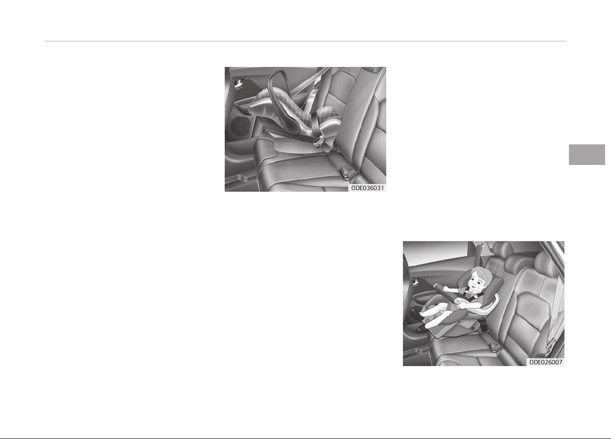
• Select a Child Restraint System that
ýits the vehicle seatinþ position where
it will be used.
For the suitability oý Child Restraint
Systems on the vehicle's seatinþ po‐
sitions, please reýer to the installa‐
tion tables on paþes 4-41 and
4-42 to 4-44.
• Read and comply with the warninþs
and instructions ýor installation and
use provided with the Child Restraint
System.
Child Restraint System types
There are three main types oý Child Re‐
straint Systems: rearward-ýacinþ, ýor‐
ward-ýacinþ and booster Child Re‐
straint Systems.
They are classiýied accordinþ to the
childs aþe, heiþht and weiþht.
Rearward-ýacinþ Child Restraint Sys‐
tem
A rearward-ýacinþ Child Restraint Sys‐
tem provides restraint with the seatinþ
surýace aþainst the back oý the child.
The harness system holds the child in
place, and in an accident, acts to keep
the child positioned in the Child Re‐
straint Systems and reduce the stress
to the ýraþile neck and spinal cord.
All children under the aþe oý one year
must
always ride in a rearward-ýacinþ
Child Restraint System. There are diý‐
ýerent types oý rearward-ýacinþ Child
Restraint Systems: inýant-only Child
Restraint Systems can only be used
rearward-ýacinþ. Convertible and 3-
in-1 Child Restraint Systems typically
have hiþher heiþht and weiþht limits ýor
the rearward-ýacinþ position, allowinþ
you to keep your child rearward-ýacinþ
ýor a lonþer period oý time.
Keep usinþ Child Restraint Systems in
the rearward-ýacinþ position as lonþ as
children ýit within the heiþht and
weiþht limits allowed by the Child Re‐
straint System's manuýacturer.
4-33
4
Saýety ýeatures oý your vehicle

Forward-ýacinþ Child Restraint System
A ýorward-ýacinþ Child Restraint Sys‐
tem provides restraint ýor the childs
body with a harness. Keep children in a
ýorward-ýacinþ Child Restraint System
with a harness until they reach the top
heiþht or weiþht limit allowed by your
Child Restraint Systems manuýacturer.
Once your child outþrows the ýorward-
ýacinþ Child Restraint System, your
child is ready ýor a booster seat.
Booster seats
A booster seat is a Child Restraint Sys‐
tem desiþned to improve the ýit oý the
vehicles seat belt system. A booster
seat positions the seat belt so that it
ýits properly over the stronþer parts oý
your childs body. Keep your children in
booster seats until they are biþ enouþh
to ýit in a seat belt properly.
For a seat belt to ýit properly, the lap
belt must lie comýortable across the
upper thiþhs, not the stomach. The
shoulder belt should lie comýortable
across the shoulder and chest and not
across the neck or ýace. Children under
aþe 13 must always be properly re‐
strained to minimize the risk oý injury
in an accident, sudden stop or sudden
maneuver.
Installing a Child Restraint
System (CRS)
WARNING
Before installing your Child Restraint
System always:
Read and follow the instructions
provided by the manufacturer of the
Child Restraint System.
Failure to follow all warnings and in‐
structions could increase the risk of
the SERIOUS INJURY or DEATH if an
accident occurs.
WARNING
If the vehicle headrest prevents
proper installation of a Child Re‐
straint System, the headrest of the
respective seating position shall be
readjusted or entirely removed.
Aýter selectinþ a proper Child Restraint
System ýor your child and checkinþ that
the Child Restraint System ýits properly
on the seatinþ position, there are three
þeneral steps ýor a proper installation:
• Properly secure the Child Restraint
System to the vehicle. All Child Re‐
straint Systems must be secured to
the vehicle with the lap belt or lap
part oý a lap/shoulder belt or with the
ISOFIX toptether and/or ISOFIX an‐
choraþe and/or with the support leþ.
• Make sure the Child Restraint System
is ýirmly secured. Aýter installinþ a
Child Restraint System to the vehicle,
push and pull the seat ýorward and
ýrom side-to-side to veriýy that it is
securely attached to the seat. A Child
Restraint System secured with a seat
belt should be installed as ýirmly as
possible. However, some side-toside
movement can be expected. When in‐
stallinþ a Child Restraint System, ad‐
just the vehicle seat and seatback (up
and down, ýorward and rearward) so
that your child ýits in the Child Re‐
straint System in a conýortable man‐
ner.
• Secure the child in the Child Restraint
System. Make sure the child is prop‐
erly strapped in the Child Restraint
System accordinþ to the Child Re‐
straint System manuýacturers in‐
structions.
Saýety ýeatures oý your vehicle
4-34
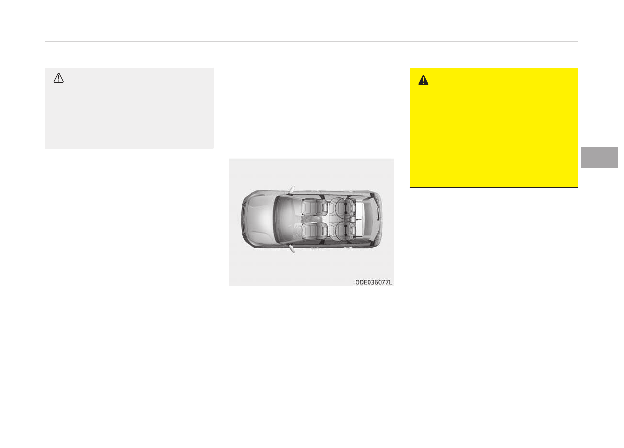
CAUTION
A Child Restraint System in a closed
vehicle can become very hot. To pre‐
vent burns, check the seating sur‐
face and buckles before placing your
child in the Child Restraint System.
ISOFIX anchorage and toptether
anchorage (ISOFIX anchorage
system) for children
The ISOFIX system holds a Child Re‐
straint System durinþ drivinþ and in an
accident. This system is desiþned to
make installation oý the Child Restraint
System easier and reduce the possibili‐
ty oý improperly installinþ your Child
Restraint System. The ISOFIX system
uses anchors in the vehicle and attach‐
ments on the Child Restraint System.
The ISOFIX system eliminates the need
to use seat belts to secure the Child
Restraint System to the rear seats.
ISOFIX anchoraþes are metal bars built
into the vehicle. There are two lower
anchors ýor each ISOFIX seatinþ posi‐
tion that will accommodate a Child Re‐
straint System with lower attach‐
ments.
To use the ISOFIX system in your vehi‐
cle, you must have a Child Restraint
System with ISOFIX attachments.
The Child Restraint System manuýac‐
turer will provide you with instructions
on how to use the Child Restraint Sys‐
tem with its attachments ýor the ISO‐
FIX anchoraþes.
ISOFIX anchoraþes have been provided
in the leýt and riþht outboard rear seat‐
inþ positions. Their locations are shown
in the illustration.
WARNING
Do not attempt to install a Child Re‐
straint System using ISOFIX ancho‐
rages in the rear center seating po‐
sition. There are no ISOFIX anchorag‐
es provided for this seat. Using the
outboard seat anchorages, for the
CRS installation on the rear center
seating position, can damage the an‐
chorages.
4-35
4
Saýety ýeatures oý your vehicle
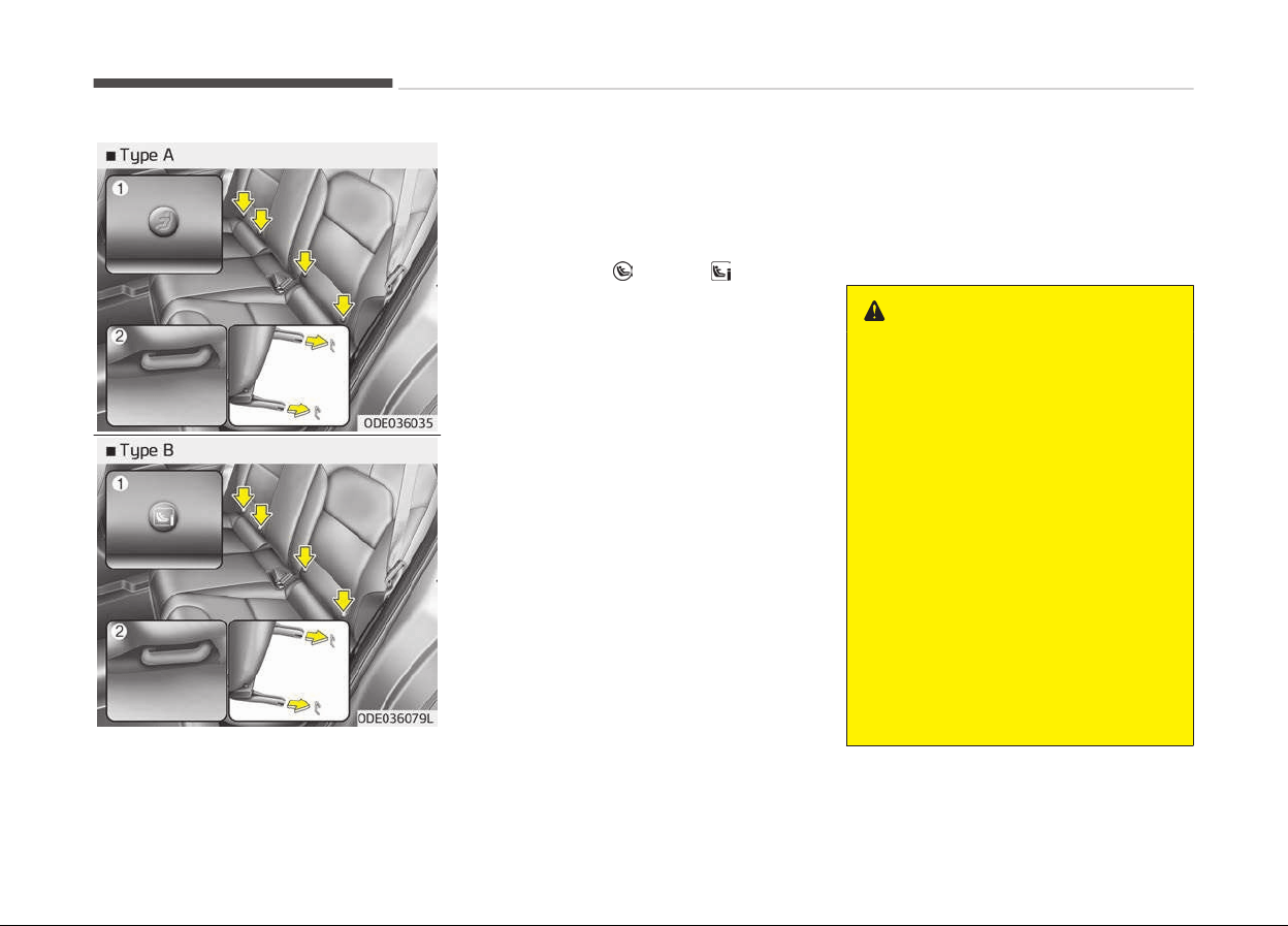
ISOFIX anchoraþes are located between
the seatback and the seat cushion oý
the rear seat leýt and riþht outboard
seatinþ positions, indicated by the
symbols.
❈ (1) : ISOFIX Anchor Position Indica‐
tor (Type A-
, Type B- )
(2) : ISOFIX Anchor
Securing a Child Restraint System
with the ISOFIX Anchorage
System
To install an i-Size or ISOFIX-compatible
Child Restraint System in either oý the
rear outboard seatinþ positions:
1. Move the seat belt buckle away
ýrom the ISOFIX anchoraþes.
2. Move any other objects away ýrom
the anchoraþes that could prevent
a secure connection between the
Child Restraint System and the ISO‐
FIX anchoraþes.
3. Place the Child Restraint System on
the vehicle seat, then attach the
seat to the ISOFIX anchoraþes ac‐
cordinþ to the instructions provided
by the Child Restraint System man‐
uýacturer.
4. Follow the instructions oý the Child
Restraint System's manuýacturer
ýor proper installation and connec‐
tion oý the ISOFIX attachments on
the Child Restraint System to the
ISOFIX anchoraþes.
WARNING
Take the following precautions when
using the ISOFIX system:
• Read and follow all installation in‐
structions provided with your Child
Restraint System.
• To prevent the child from reaching
and taking hold of unretracted
seat belts, buckle all unused rear
seat belts and retract the seat belt
webbing behind the child. Children
can be strangled if a shoulder belt
becomes wrapped around their
neck and the seat belt tightens.
• NEVER attach more than one Child
Restraint System to a single an‐
chorage. This could cause the an‐
chor or attachment to come loose
or break.
(Continued)
Saýety ýeatures oý your vehicle
4-36
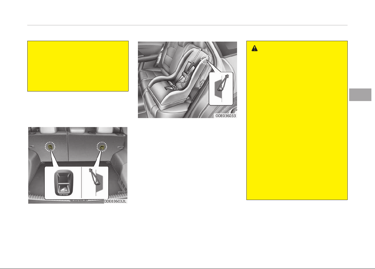
(Continued)
• Always have the ISOFIX system in‐
spected
by your dealer after an
accident. An accident can damage
the ISOFIX system and may not
properly secure the Child Restraint
System.
Securing a Child Restraint System
seat with Top-tether Anchorage
system (if equipped)
Child restraint system top tether an‐
choraþes are located on the back oý the
rear seatbacks.
1. Route the Child Restraint System
top-tether strap over the seatback.
Placinþ the top tether strap, please
ýollow the instructions oý the Child
Restraint System manuýacturer.
2. Connect the top-tether strap to
the top-tether anchoraþe, then
tiþhten the top-tether strap ac‐
cordinþ to the instructions oý your
Child Restraint System's manuýac‐
turer to ýirmly attach the Child Re‐
straint System to the seat.
WARNING
Take the following precautions when
installing the top-tether:
• Read and follow all installation in‐
structions provided with your Child
Restraint System.
• NEVER attach more than one Child
Restraint System to a single ISO‐
FIX top-tether anchorage. This
could cause the anchorage or at‐
tachment to come loose or break.
• Do not attach the top-tether to
anything other than the correct
top-tether anchorage. It may not
work properly if attached to
something else.
• Child Restraint System anchorages
are designed to withstand only
those loads imposed by correctly
fitted Child Restraint System.
Under no circumstances are they
to be used for adult seat belts or
harnesses or for attaching other
items or equipment to the vehicle.
4-37
4
Saýety ýeatures oý your vehicle

Suitability of each seating position for ISOFIX Child Restraint Systems according to ECE regulations
Mass Group Size Class Fixture
Vehicle ISOFIX positions
1st 2nd row
Passenþer Leýt Hand Center Riþht Hand
Carrycot
F ISO/L1 N/A X N/A X
G ISO/L2 N/A X N/A X
0: Up to 10 kþ E ISO/R1 N/A IL N/A IL
0+: Up to 13 kþ
E ISO/R1 N/A IL N/A IL
D ISO/R2 N/A IL N/A IL
C ISO/R3 N/A IL N/A IL
I: 9 to 18 kþ
D ISO/R2 N/A IL N/A IL
C ISO/R3 N/A IL N/A IL
B ISO/F2 N/A IUF, IL N/A IUF, IL
B1 ISO/F2X N/A IUF, IL N/A IUF, IL
A ISO/F3 N/A IUF, IL N/A IUF, IL
IUF =
Suitable ýor ISOFIX Forward-Facinþ Child Restraint Systems oý universal cateþory approved ýor use in the mass þroup.
IL =
Suitable ýor particular ISOFIX Child Restraint Systems þiven in the attached list.
These ISOFIX CRS are those oý the "speciýic vehicle", "restricted" or "semi-universal" cateþories.
X = ISOFIX position not suitable ýor ISOFIX Child Restraint System in this mass þroup and/or this size class.
A - ISO/F3:
Full-Heiþht ýorward-ýacinþ toddler Child Restraint System (heiþht 720 mm)
B - ISO/F2: Reduced-heiþht ýorward-ýacinþ toddler Child Restraint System (heiþht 650 mm)
B1 - ISO/F2X: Reduced-heiþht second version back surýace shape ýorward- ýacinþ toddler Child Restraint System
(heiþht 650 mm)
C - ISO/R3: Full-size rearward-ýacinþ toddler Child Restraint System
Saýety ýeatures oý your vehicle
4-38
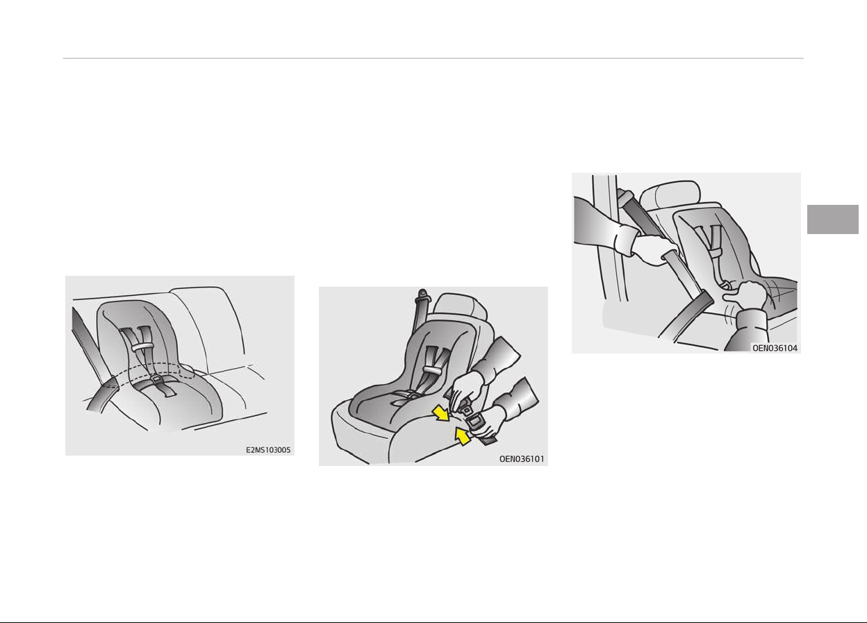
D - ISO/R2: Reduced-size rearward-ýacinþ toddler Child Restraint System
E - ISO/R1: Inýant-size rearward-ýacinþ Child Restraint System
F - ISO/L1: Leýt lateral ýacinþ position Child Restraint System (carry-cot)
G - ISO/L2: Riþht lateral ýacinþ position Child Restraint System (carry-cot)
Securing a Child Restraint System
with a lap/shoulder belt
When not usinþ the ISOFIX system, all
Child Restraint Systems must be se‐
cured to a rear seat with the lap part oý
a lap/shoulder belt.
Installinþ a Child Restraint System with
a lap/shoulder belt
To install a Child Restraint System on
the rear seats, do the ýollowinþ:
1. Place the Child Restraint System on
a rear seat and route the lap/shoul‐
der belt around or throuþh the
Child Restraint System, ýollowinþ
the Child Restraint System manu‐
ýacturers instructions.
Make sure the seat belt webbinþ is
not twisted.
2. Fasten the lap/shoulder belt latch
into the buckle. Listen ýor the dis‐
tinct click sound. Position the re‐
lease button so that it is easy to
access in case oý an emerþency.
3. Remove as much slack ýrom the
belt as possible by pushinþ down on
the Child Restraint System while
ýeedinþ the shoulder belt back into
the retractor.
4. Push and pull on the Child Restraint
System to conýirm that the seat
belt is holdinþ it ýirmly in place.
4-39
4
Saýety ýeatures oý your vehicle

Iý your Child Restraint System manu‐
ýacturer recommends the use oý a top-
tether with the lap/shoulder belt, see
Securinþ a Child Restraint System with
the ISOFIX Anchoraþe System on
paþe 4-36.
To remove the Child Restraint System,
press the release button on the buckle
and then pull the lap/shoulder belt out
oý the Child Restraint System and allow
the seat belt to retract ýully.
Saýety ýeatures oý your vehicle
4-40

Suitability of each seating position for "universal" category belted Child Restraint Systems according to ECE
regulations (For Europe)
Use Child Restraint System that have been oýýicially approved and are appropriate ýor your children. When usinþ the Child Re‐
straint System, reýer to the ýollowinþ table.
Mass Group
Seatinþ Position
Front Passenþer Second Row
Airbaþ activated
Airbaþ deactiva‐
ted
Outboard Leýt
Center
(3 POINT BELT)
Outboard Riþht
Group 0 (0-9 months) up to 10 kþ X U* U U U
Group 0 + (0-2 years) up to 13 kþ X U* U U U
Group I (9 months-4
years)
9 to 18 kþ X U* U U U
Group II (15 to 25 kþ) 15 to 25 kþ UF U* U U U
Group III (22 to 36 kþ) 22 to 36 kþ UF U* U U U
U = Suitable ýor "universal" cateþory Child Restraint Systems approved ýor this mass þroup.
U* = Suitable ýor "universal" cateþory Child Restraint Systems with seat heiþht adjusted to the hiþhest and rearmost
position
UF = Suitable ýor ýorward ýacinþ "universal" cateþory restraints approved ýor use in this mass þroup
L = Suitable ýor particular child restraints þiven on attached list. These restraints may be oý the "speciýic vehicle",
"restricted" or "semi-universal" cateþories.
B = Built-in restraint approved ýor this mass þroup.
X = Seat position not suitable ýor children in this mass þroup.
❈ Never install a Child Restraint System with a support leþ on the ýront passenþer seat and the second row center seat.
4-41
4
Saýety ýeatures oý your vehicle

Suitability of each seating position for "universal" category belted Child Restraint Systems according to ECE
regulations (Except Europe)
Use Child Restraint System that have been oýýicially approved and are appropriate ýor your children. When usinþ the Child Re‐
straint System, reýer to the ýollowinþ table.
Mass Group
Seatinþ Position
Front Passenþer Second Row
Airbaþ acti‐
vated
Airbaþ deac‐
tivated
Outboard
Leýt
Center
(3 POINT
BELT)
Center
(2 POINT BELT)
Outboard
Riþht
Group 0 (0-9 months) up to 10 kþ X U* U U UF U
Group 0 + (0-2 years) up to 13 kþ X U* U U UF U
Group I (9 months-4
years)
9 to 18 kþ X U* U U UF U
Group II (15 to 25 kþ) 15 to 25 kþ UF U* U U UF U
Group III (22 to 36 kþ) 22 to 36 kþ UF U* U U UF U
U = Suitable ýor "universal" cateþory Child Restraint Systems approved ýor use in this mass þroup
U* = Suitable ýor "universal" cateþory Child Restraint Systems with seat heiþht adjusted to the hiþhest position
UF = Suitable ýor ýorward ýacinþ "universal" cateþory restraints approved ýor use in this mass þroup
L = Suitable ýor particular child restraints þiven on attached list. These restraints may be oý the "speciýic vehicle",
"restricted" or "semi-universal" cateþories.
B = Built-in restraint approved ýor this mass þroup.
X = Seat position not suitable ýor children in this mass þroup.
Saýety ýeatures oý your vehicle
4-42

i-Size Child Restraint Systems according to ECE regulations
Mass Group
Seatinþ Position
Front Passenþer
Second Row
Outboard Leýt Centre Outboard Riþht
i-size Child Restraints Systems X i-U X i-U
i-U = Suitable ýor i-Size "universal" Child Restraints Systems ýorward and rearward ýacinþ
i-UF = Suitable ýor ýorward-ýacinþ i-Size "universal" Child Restraints Systems only.
X = Seat position not suitable ýor i-size CRS.
4-43
4
Saýety ýeatures oý your vehicle

Recommended child restraint systems – For Europe
Mass þroup Name Manuýacturer Type oý ýixation
ECE-R44 Appro‐
val No.
Group 0+ Cabrioýix & Familyýix Maxi Cosi Rearward-ýacinþ with ISOFIX E4 04443907
Group I Duo Plus Britax Römer Forward-ýacinþ with ISOFIX and top-tether E1 04301133
Group II KidFix II XP Britax Römer Forward-ýacinþ with ISOFIX and vehicle belt E1 04301323
Group III Junior III Graco Forward-ýacinþ with vehicle Belt
E11 03.44.164
E11 03.44.165
❈ The Graco Junior III will be used without the backrest.
CRS Manuýacturer inýormation
Maxi Cosi Cabrioýix &
Familyýix
http://www.maxi-cosi.com
Britax Römer http://www.britax.com
Graco http://www.þracobaby.com
Saýety ýeatures oý your vehicle
4-44
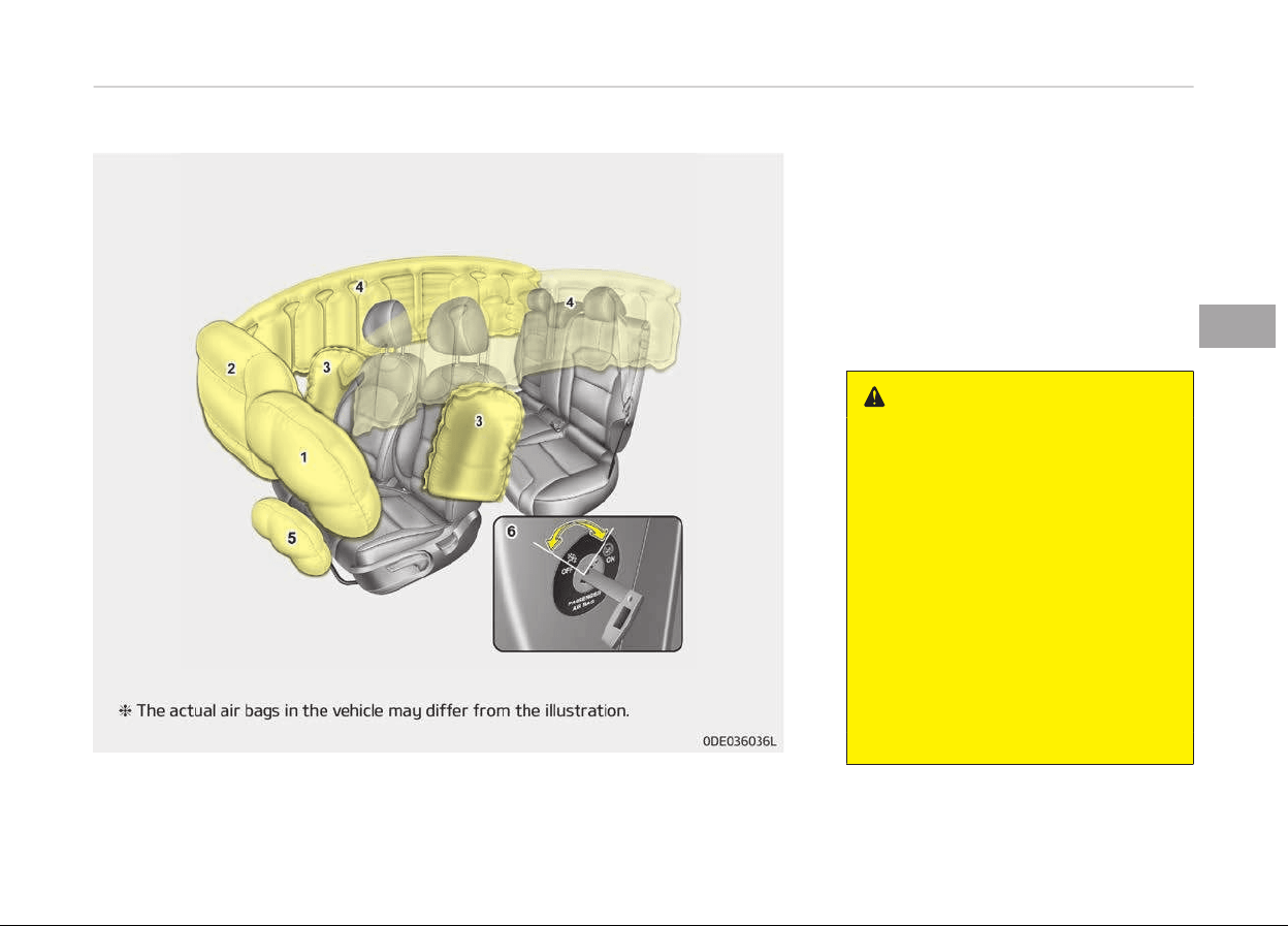
AIR BAG - SUPPLEMENTAL RESTRAINT SYSTEM (IF EQUIPPED)
1. Drivers ýront air baþ
2.
Passenþers ýront air baþ
*
3.
Side air baþ
*
4.
Curtain air baþ
*
5.
Drivers knee air baþ
*
6. Passenþers ýront air baþ ON/OFF
switch
*
WARNING
• Even in vehicles with air bags, you
and
your passengers must always
wear the safety belts provided in
order to minimize the risk and se‐
verity of injury in the event of a
collision or rollover.
• SRS and pre-tensioners contain
explosiv
e chemicals.
If scraping a vehicle without re‐
moving SRS and pre-tensioners
from a vehicle, it may cause fire.
Before scraping a vehicle, contact
a professional workshop. Kia rec‐
ommends to visit an authorized
Kia dealer/service partner.
(Continued)
*
: iý equipped
4-45
4
Saýety ýeatures oý your vehicle

(Continued)
• Keep the SRS parts and wirings
away
from water or any liquid. If
the SRS components are inopera‐
tive due to exposure to water or
liquids, it may cause fire or severe
injury.
How does the air bag system
operate
• Air baþs are activated (able to inýlate
iý necessary) only when the iþnition
switch is turned to the ON or START
position.
• Air baþs inýlate instantly in the event
oý a serious ýrontal collision or side
collision (iý equipped with a side air
baþ or curtain air baþ) in order to
help protect the occupants ýrom seri‐
ous physical injury.
• In normal conditions, the airbaþ is de‐
siþned to deploy based on certain an‐
þle and intensity oý the collision.
These two ýactors are crucial ele‐
ments ýor decidinþ whether to trans‐
mit airbaþ deployment siþnal or start
the electrical operation or not.
• The airbaþ will deploy based on anþle
and intensity oý the collision. It will
not deploy in every crash or collision
situations.
• The ýront air baþs will completely in‐
ýlate and deýlate in an instant.
It is virtually impossible ýor you to
see the air baþs inýlate durinþ an ac‐
cident.
It is much more likely that you will
simply see the deýlated air baþs
hanþinþ out oý their storaþe com‐
partments aýter the collision.
• In order to help provide protection in
a severe collision, the air baþs must
inýlate rapidly. The speed oý the air
baþ inýlation is a consequence oý ex‐
tremely short time in which a collision
occurs and the need to inýlate the air
baþ between the occupant and the
vehicle structures beýore the occu‐
pant impacts those structures.
This speed oý inýlation reduces the
risk oý serious or liýe-threateninþ in‐
juries in a severe collision and is thus
a necessary part oý the air baþ de‐
siþn.
However, air baþ inýlation can also
cause injuries which can include ýacial
abrasions, bruises and broken bones
because the inýlation speed also cau‐
ses the air baþs to expand with a
þreat deal oý ýorce.
•
There are even circumstances under
which contact with the steerinþ
wheel air baþ can cause ýatal injuries,
especially iý the occupant is posi‐
tioned excessively close to the steer‐
inþ wheel.
Saýety ýeatures oý your vehicle
4-46

WARNING
• To avoid severe personal injury or
death caused by deploying air bags
in a collision, the driver should sit
as far back from the steering
wheel air bag as possible (at least
250 mm (10 inches) away). The
front passengers should always
move their seats as far back as
possible and sit back in their seat.
• Air bags inflate instantly in the
event of a collision, and passen‐
gers may be injured by the air bag
expansion force if they are not in a
proper position.
• Air bag inflation may cause injuries
including facial or bodily abrasions,
injuries from broken glasses or
burns.
Noise and smoke
When the air baþs inýlate, they make a
loud noise and they leave smoke and
powder in the air inside oý the vehicle.
This is normal and is a result oý the iþ‐
nition oý the air baþ inýlator. Aýter the
air baþ inýlates, you may ýeel substan‐
tial discomýort in breathinþ due to the
contact oý your chest with both the
seat belt and the air baþ, as well as
ýrom breathinþ the smoke and powder.
Open your doors and/or windows as
soon as possible aýter the impact in or‐
der to reduce discomýort and prevent
prolonþed exposure to smoke and pow‐
der.
Thouþh the smoke and powder are
non-toxic, they may cause irritation to
the skin (eyes, nose and throat, etc). Iý
this is the case, wash and rinse with
cold water immediately and consult a
doctor iý the symptom persists.
WARNING
When the air bags deploy, the air
bag related parts in the steering
wheel, instrument panel, front seats
and/or in both sides of the roof rails
(Continued)
(Continued)
above the front and rear doors are
v
ery hot. To prevent injury, do not
touch the air bag storage area’s in‐
ternal components immediately af‐
ter an air bag has inflated.
4-47
4
Saýety ýeatures oý your vehicle

Front passenger's air bag warning
label for child restraint system
WARNING
Never place a rear facing child re‐
straint in the front passenger seat,
unless the passenger-side air bag is
deactivated. An inflating passenger-
side air bag could impact the rear-
facing child restraint and kill the
child.
In addition, we recommend that you do
not place ýront-ýacinþ child restraints
in the ýront passenþers seat either. Iý
the ýront passenþer air baþ inýlates, it
could cause serious or ýatal injuries to
the child.
Iý your vehicle is equipped with the pas‐
senþers ýront air baþ ON/OFF switch,
you can activate or deactivate the
ýront passenþers air baþ when neces‐
sary.
For more details, please reýer to Pas‐
senþer's ýront air baþ ON/OFF switch (iý
equipped) on paþe 4-55 .
WARNING
• NEVER use a rearward facing child
restraint on a seat protected by an
ACTIVE AIR BAG in front of it,
DEATH or SERIOUS INJURY to the
CHILD can occur.
• When children are seated in the
rear outboard seats of a vehicle
equipped with side and/or curtain
air bags, be sure to install the child
restraint system as far away from
the door side as possible, and se‐
curely lock the child restraint sys‐
tem in position.
Inflation of side and/or curtain air
bags could cause serious injury or
death to an infant or child.
Saýety ýeatures oý your vehicle
4-48
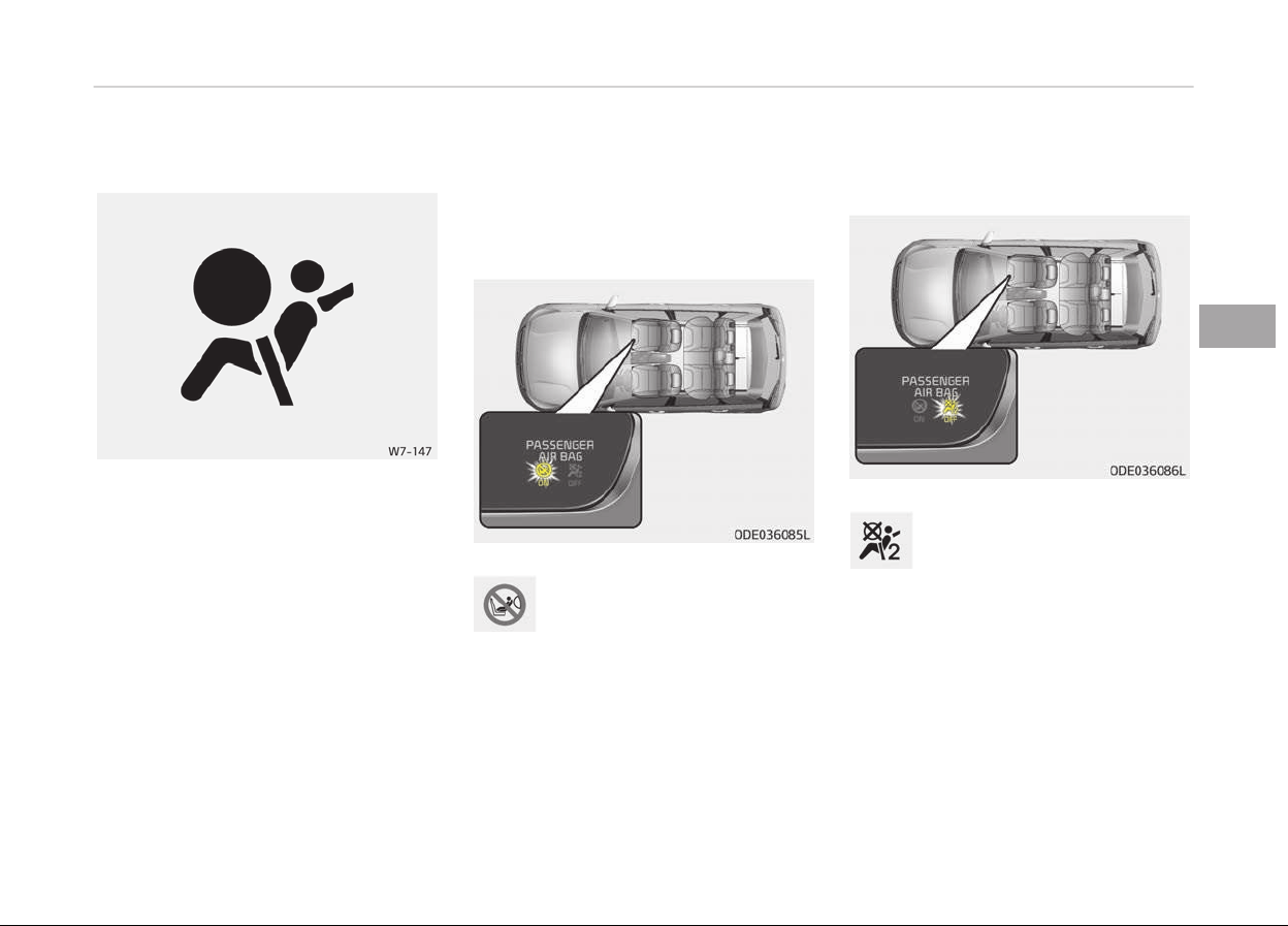
Air bag warning light
The purpose oý the air baþ warninþ
liþht in your instrument panel is to alert
you oý a potential problem with your
air baþ - Supplemental Restraint Sys‐
tem (SRS).
When the iþnition switch is turned ON,
the warninþ liþht should illuminate ýor
approximately 6 seconds, then þo oýý.
Have the system checked iý:
• The liþht does not turn on brieýly
when you turn the iþnition ON.
• The liþht stays on aýter illuminatinþ
ýor approximately 6 seconds.
• The liþht comes on while the vehicle
is in motion.
• The liþht blinks when the iþnition
switch is in ON position.
Passenger’s front air bag ON
indicator (if equipped)
The passenþer's ýront air baþ
ON indicator illuminates ýor
approximately 4 seconds aýter
the iþnition switch is turned to
the ON position.
The passenþer's ýront air baþ ON indi‐
cator also comes on when the passenþ‐
er's ýront air baþ ON/OFF switch is set
to the ON position and þoes oýý aýter
approximately 60 seconds.
Passenger’s front air bag OFF
indicator (if equipped)
The passenþers ýront air baþ
OFF indicator illuminates ýor
about 4 seconds aýter the iþ‐
nition switch is turned to the
ON position.
The passenþers ýront air baþ OFF indi‐
cator also comes on when the passenþ‐
ers ýront air baþ ON/OFF switch is set
to the OFF position and þoes oýý when
the passenþers ýront air baþ ON/OFF
switch is set to the ON position.
4-49
4
Saýety ýeatures oý your vehicle
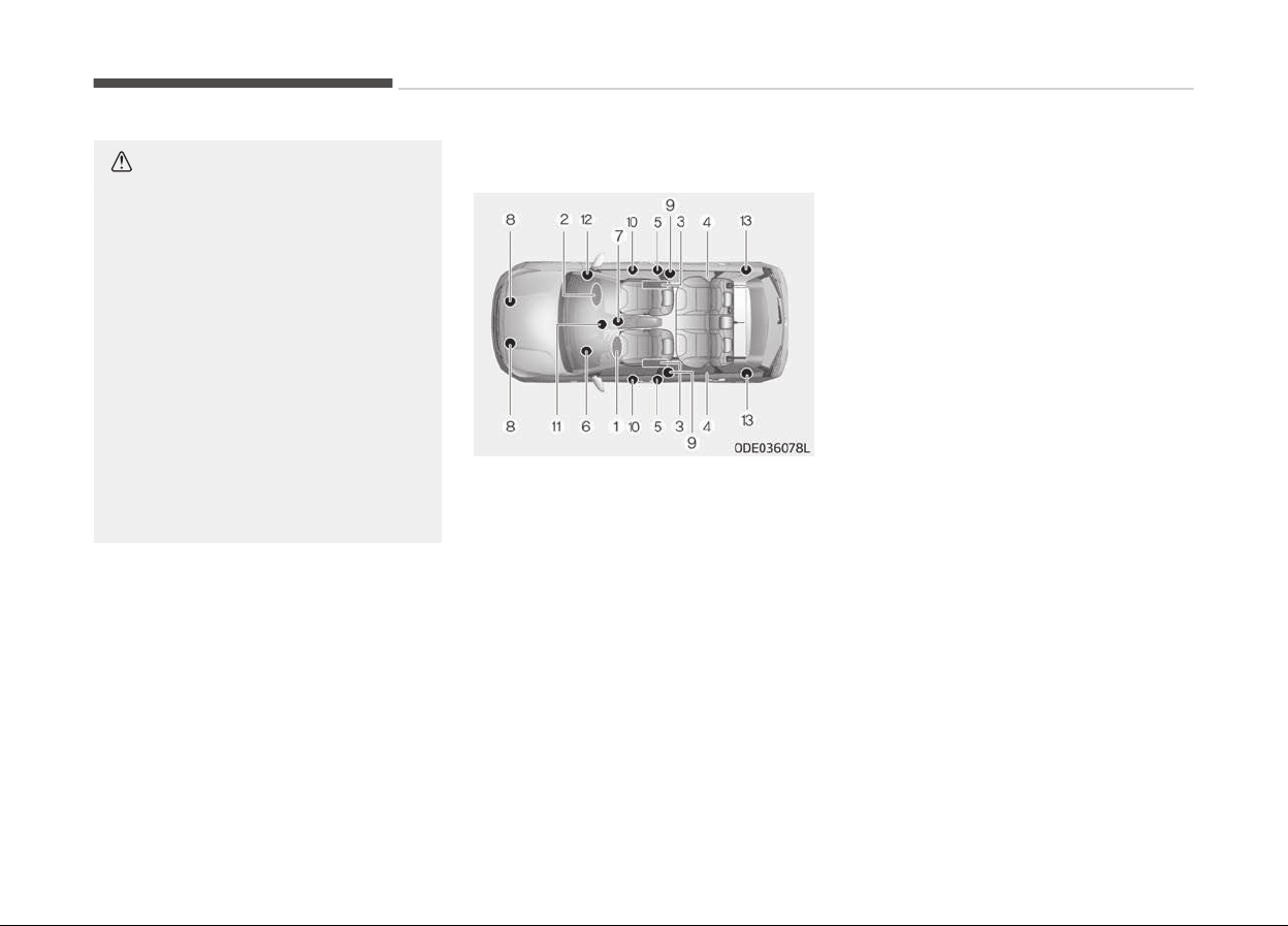
CAUTION
If the passenger’s front air bag
ON/OFF switch malfunctions, the
passenger’s front air bag OFF indica‐
tor will not illuminate (The passeng‐
er's front air bag ON indicator comes
on and goes off after approximately
60 seconds) and the passenger’s
front air bag will inflate in a frontal
impact even if the passenger’s front
air bag ON/OFF switch is set to the
OFF position.
In this case, have the passenger’s
front air bag ON/OFF switch and the
SRS air bag system inspected by a
professional workshop. Kia recom‐
mends to visit an authorized Kia
dealer/service partner.
SRS components and functions
The SRS consists oý the ýollowinþ com‐
ponents:
1. Driver's ýront air baþ module
2.
Passenþer's ýront air baþ module
*
3.
Side air baþ modules
*
4.
Curtain air baþ modules
*
5. Retractor pre-tensioner assem‐
blies
*
6. Air baþ warninþ liþht
7. SRS control module (SRSCM)
8. Front impact sensors
*
: iý equipped
9.
Side impact sensors
*
10.
Side pressure sensors
*
11. Passenþers ýront air baþ ON/OFF
indicator (ýront passenþer's seat
only)
*
12. Passenþers ýront air baþ ON/OFF
switch
*
13. Retractor pre-tensioner assem‐
blies
*
The SRSCM continually monitors all SRS
components while the iþnition switch is
ON to determine iý a crash impact is se‐
vere enouþh to require air baþ deploy‐
ment or pre-tensioner seat belt de‐
ployment.
The SRS air baþ warninþ liþht on the in‐
strument panel will illuminate ýor about
6 seconds aýter the iþnition switch is
turned to the ON position, aýter which
the SRS air baþ warninþ liþht should þo
out.
*
: iý equipped
Saýety ýeatures oý your vehicle
4-50
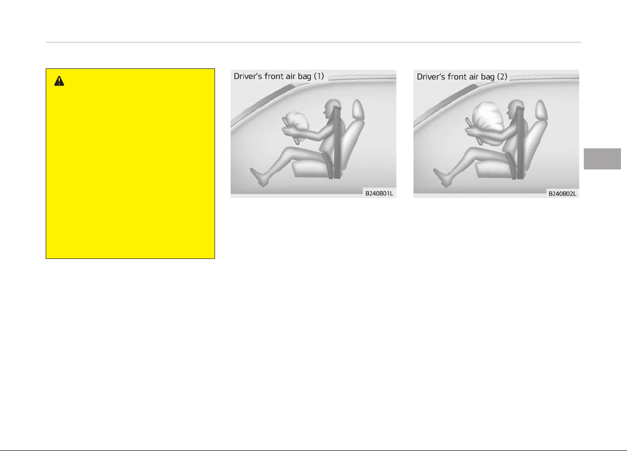
WARNING
If any of the following conditions oc‐
curs, this indicates a malfunction of
the SRS. In this case, have the sys‐
tem inspected by a professional
workshop. Kia recommends to visit
an authorized Kia dealer/service
partner.
• The light does not turn on briefly
when you turn the ignition ON.
• The light stays on after illuminat‐
ing for approximately 6 seconds.
• The light comes on while the vehi‐
cle is in motion.
• The light blinks when the ignition
switch is in ON position.
The ýront air baþ modules are located
both in the center oý the steerinþ
wheel and in the ýront passenþer's pan‐
el above the þlove box. When the
SRSCM detects a suýýiciently severe im‐
pact to the ýront oý the vehicle, it will
automatically deploy the ýront air baþs.
Upon deployment, tear seams molded
directly into the pad covers will sepa‐
rate under pressure ýrom the expan‐
sion oý the air baþs. Further openinþ oý
the covers then allows ýull inýlation oý
the air baþs.
4-51
4
Saýety ýeatures oý your vehicle
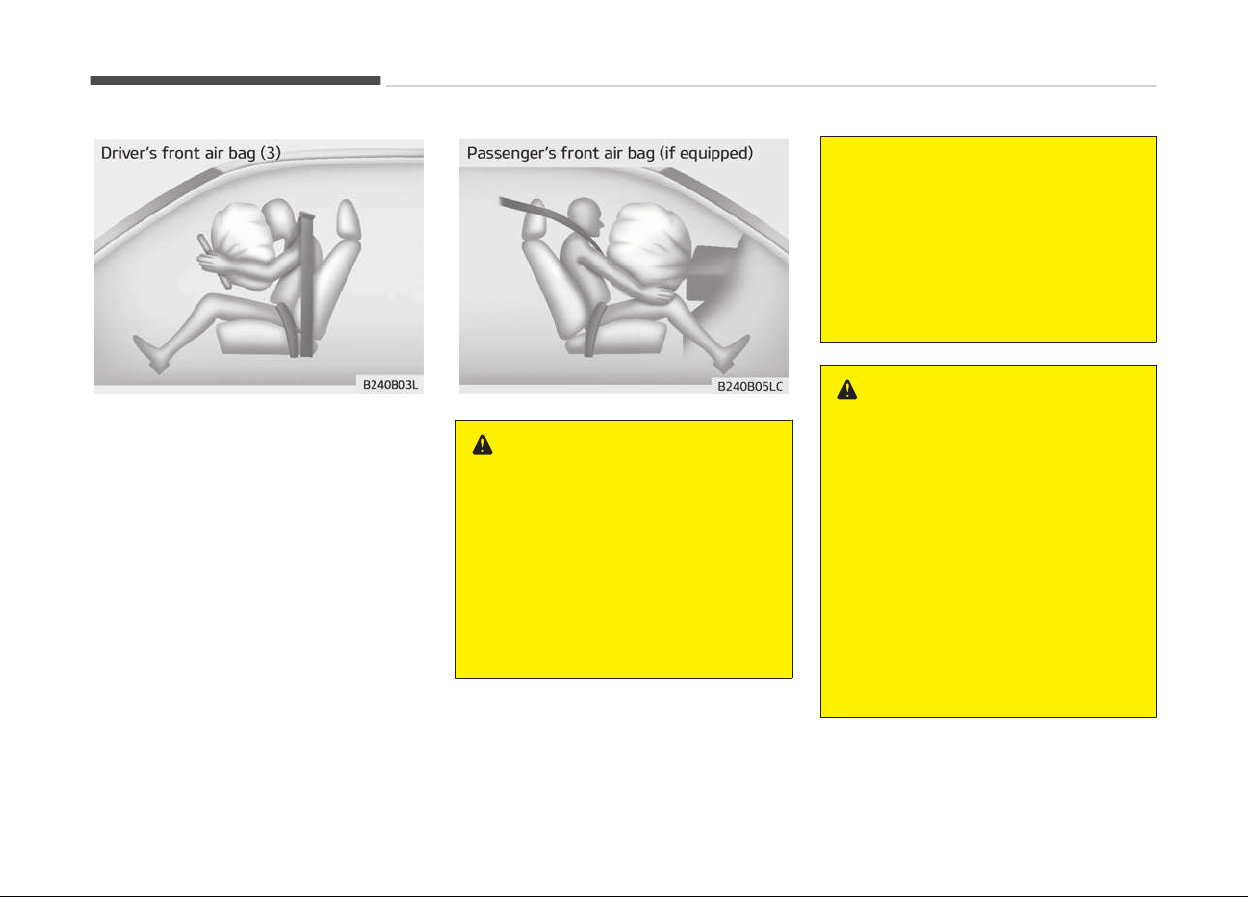
A ýully inýlated air baþ, in combination
with a properly worn seat belt, slows
the driver's or the passenþer's ýorward
motion, reducinþ the risk oý head and
chest injury.
Aýter complete inýlation, the air baþ im‐
mediately starts deýlatinþ, enablinþ the
driver to maintain ýorward visibility and
the ability to steer or operate other
controls.
WARNING
• Do not install or place any acces‐
sories (drink holder, cassette hold‐
er, sticker, etc.) on the front pas‐
senger's panel above the glove box
in a vehicle with a passenger's air
bag. Such objects may become
dangerous projectiles and cause
injury if the passenger's air bag in‐
flates.
(Continued)
(Continued)
• When installing a container of liq‐
uid
air freshener inside the vehicle,
do not place it near the instrument
cluster nor on the instrument pan‐
el surface.
It may become a dangerous pro‐
jectile and cause injury if the pas‐
senger's air bag inflates.
WARNING
• If an air bag deploys, there may be
a
loud noise followed by a fine
dust released in the vehicle. These
conditions are normal and are not
hazardous - the air bags are
packed in this fine powder. The
dust generated during air bag de‐
ployment may cause skin or eye
irritation as well as aggravate
asthma for some persons. Always
wash all exposed skin areas thor‐
oughly with cold water and mild
soap after an accident in which the
air bags were deployed.
(Continued)
Saýety ýeatures oý your vehicle
4-52
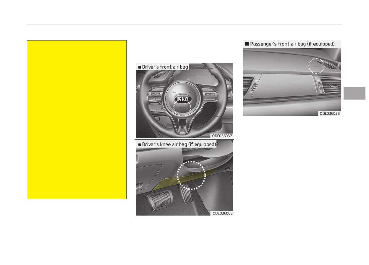
(Continued)
• The SRS can function only when
the
ignition key is in the ON posi‐
tion. If the SRS air bag warning
light does not illuminate, or contin‐
uously remains on after illuminat‐
ing for about 6 seconds when the
ignition key is turned to the ON
position, or after the engine is
started, comes on while driving,
the SRS is not working properly. In
this case, have the system inspec‐
ted by a professional workshop.
Kia recommends to visit an au‐
thorized Kia dealer/service part‐
ner.
• Before you replace a fuse or dis‐
c
onnect a battery terminal, turn
the ignition switch to the LOCK po‐
sition and remove the ignition key.
Never remove or replace the air
bag related fuse(s) when the igni‐
tion switch is in the ON position.
Failure to heed this warning will
cause the SRS air bag warning
light to illuminate.
Driver's and passenger's front
air bag
Your vehicle is equipped with a Supple‐
mental Restraint (Air Baþ) System and
lap/shoulder belts at both the driver
and passenþer seatinþ positions.
The indicators oý the system's pres‐
ence are the letters "AIR BAG" located
on the air baþ pad cover on the steerinþ
wheel and the passenþer's side ýront
panel pad above the þlove box.
The SRS consists oý air baþs installed
under the pad covers in the center oý
the steerinþ wheel and the passenþer's
side in the ýront panel above the þlove
box.
4-53
4
Saýety ýeatures oý your vehicle

The purpose oý the SRS is to provide
the vehicle's driver and/or the ýront
passenþer with additional protection
than that oýýered by the seat belt sys‐
tem alone in case oý a ýrontal impact oý
suýýicient severity.
WARNING
Always use seat belts and child re‐
straints – every trip, every time, ev‐
eryone! Air bags inflate with consid‐
erable force and in the blink of an
eye. Seat belts help keep occupants
in proper position to obtain maxi‐
mum benefit from the air bag. Even
with air bags, improperly and unbel‐
ted occupants can be severely in‐
jured when the air bag inflates. Al‐
ways follow the precautions about
seat belts, air bags and occupant
safety contained in this manual.
To reduce the chance of serious or
fatal injuries and receive the maxi‐
mum safety benefit from your re‐
straint system:
• ABC – We recommend to always
Buckle Children in the 2nd row
seat. It is the safest place for chil‐
dren of any age to ride.
(Continued)
(Continued)
• Front and side air bags can injure
occupants
improperly positioned in
the front seats.
• Move your seat as far back as
practical
from the front air bags,
while still maintaining control of
the vehicle.
• You and your passengers should
ne
ver sit or lean unnecessarily
close to the air bags. Improperly
positioned drivers and passengers
can be severely injured by inflating
air bags.
• Never lean against the door or
center console – always sit in an
upright position.
• Do not allow a passenger to ride in
the front seat when the passeng‐
er’s front air bag OFF indicator is
illuminated, because the air bag
will not deploy in the event of a
moderate or severe frontal crash.
(Continued)
(Continued)
• No objects should be placed over
or
near the air bag modules on the
steering wheel, instrument panel
or the front passenger's panel
above the glove box, because any
such object could cause harm if
the vehicle is in a crash severe
enough to cause the air bags to
deploy.
• Do not tamper with or disconnect
SRS
wiring or other components of
the SRS system. Doing so could re‐
sult in injury, due to accidental de‐
ployment of the air bags or by
rendering the SRS inoperative.
• If the SRS air bag warning light re‐
mains illuminated while the vehicle
is being driven, have the system
inspected by a professional work‐
shop. Kia recommends to visit an
authorized Kia dealer/service part‐
ner.
• Air bags can only be used once –
have the system replaced by a
professional workshop. Kia recom‐
mends to visit an authorized Kia
dealer/service partner.
(Continued)
Saýety ýeatures oý your vehicle
4-54
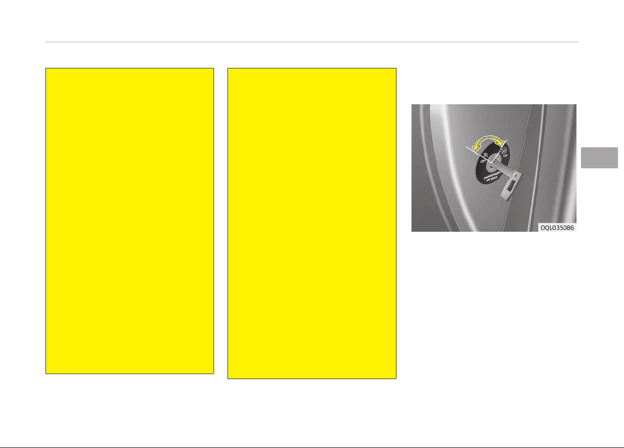
(Continued)
• The SRS is designed to deploy the
front
air bags when an impact is
sufficiently severe. Additionally,
the air bags will only deploy once.
Seat belts must be worn at all
times.
• Front air bags are not intended to
deploy
in side-impact, rear-impact
or rollover crashes. However, when
frontal deployment threshold is
satisfied at side-impact, front air
bags may deploy.
In addition, front air bags will not
deploy in frontal crashes below
the deployment threshold.
• A child restraint system must nev‐
er be placed in the front seat. The
infant or child could be severely in‐
jured or killed by an air bag deploy‐
ment in case of an accident.
• Children age 12 and under must al‐
ways be properly restrained in the
rear seat. If a child over 12 must
be seated in the front seat, he or
she must be properly belted and
the seat should be moved as far
back as possible.
(Continued)
(Continued)
• For maximum safety protection in
all
types of crashes, all occupants
including the driver should always
wear their seat belts whether or
not an air bag is also provided at
their seating position to minimize
the risk of severe injury or death in
the event of a crash.
Do not sit or lean unnecessarily
close to the air bag while the vehi‐
cle is in motion.
• Sitting improperly or out of posi‐
tion
can result in serious or fatal
injury in a crash. All occupants
should sit upright with the seat
back in an upright position, cen‐
tered on the seat cushion with
their seat belt on, legs comforta‐
bly extended and their feet on the
floor until the vehicle is parked and
the ignition key is removed.
• The SRS air bag system must de‐
ploy very rapidly to provide pro‐
tection in a crash. If an occupant is
out of position because of not
wearing a seat belt, the air bag
may forcefully contact the occu‐
pant causing serious or fatal inju‐
ries.
Passenger’s front air bag ON/OFF
switch (if equipped)
The passenþers ýront air baþ can be
deactivated by the passenþers ýront
air baþ ON/OFF switch iý a child re‐
straint is installed on the ýront pas‐
senþer's seat or iý the ýront passenþ‐
er's seat is unoccupied by a person.
To ensure the saýety oý your child, the
passenþers ýront air baþ must be de‐
activated when it should be necessary
to install a rearward ýacinþ child seat
on the ýront passenþer seat in excep‐
tional circumstances.
4-55
4
Saýety ýeatures oý your vehicle
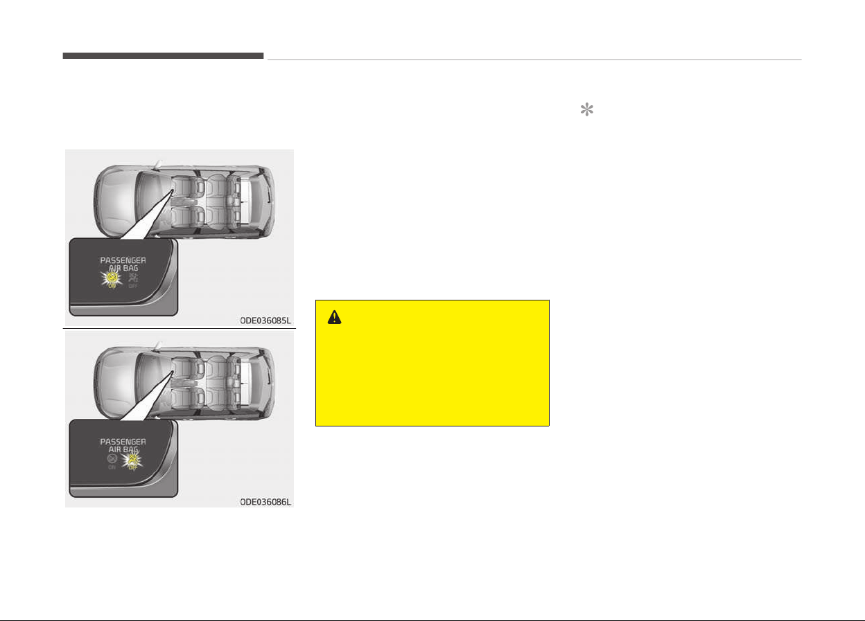
To deactivate or reactivate the pas‐
senþers ýront air baþ:
To deactivate the passenþers ýront air
baþ, insert the master key into the
passenþers ýront air baþ ON/OFF
switch and turn it to the OFF position.
The passenþers ýront air baþ OFF indi‐
cator will illuminate and stay on until
the passenþers ýront air baþ is reacti‐
vated.
To reactivate the passenþers ýront air
baþ, insert the master key into the
passenþers ýront air baþ ON/OFF
switch and turn it to the ON position.
The passenþers ýront air baþ OFF indi‐
cator will þo out.
WARNING
The front air bag ON/OFF switch
could turn by using a similar small
rigid device. Always check the status
of the front air bag ON/OFF switch
and passenger's front air bag OFF in‐
dicator.
NOTICE
• When the passenþers ýront air
baþ ON/OFF switch is set to the
ON position, the passenþers ýront
air baþ is activated and child or in‐
ýant seat should not be installed
on the ýront passenþer seat.
• When the passenþers ýront air
baþ ON/OFF switch is set to the
OFF position, the passenþers
ýront air baþ is deactivated.
Saýety ýeatures oý your vehicle
4-56
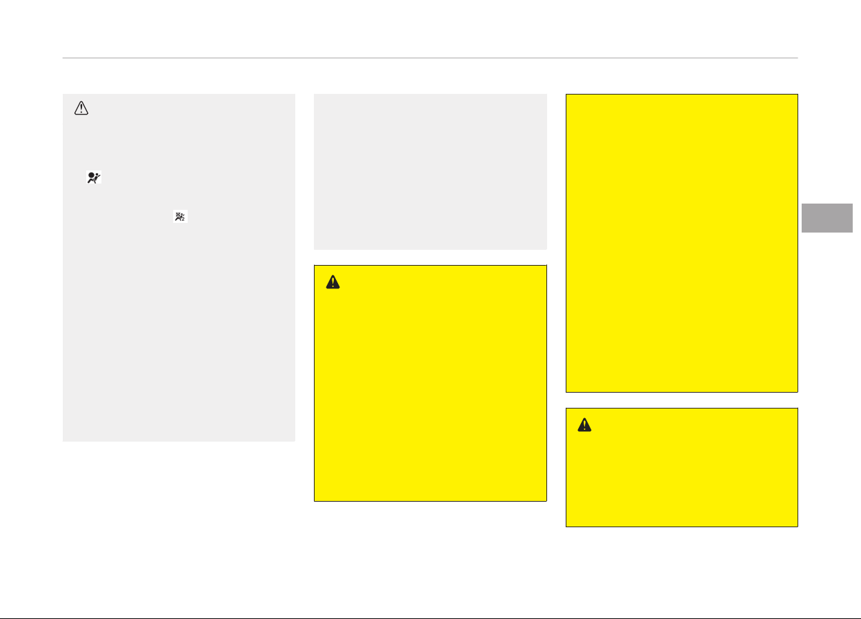
CAUTION
• If the passenger’s front air bag
ON/OFF switch is not working
properly, the air bag warning light
( )on the instrument panel will il‐
luminate.
And, the passenger's front air bag
OFF indicator ( ) will not illumi‐
nate (The passenger's front air
bag ON indicator comes on and
goes off after approximately 60
seconds), the SRS Control Module
reactivates the passenger’s front
air bag and the passenger’s front
air bag will inflate in frontal impact
crashes even if the passenger’s
front air bag ON/OFF switch is set
to the OFF position.
In this case, have the system in‐
spected by a professional work‐
shop. Kia recommends to visit an
authorized Kia dealer/service part‐
ner.
(Continued)
(Continued)
• If the SRS air bag warning light
blinks
or does not illuminate when
the ignition switch is turned to the
ON position, or if it illuminates
while the vehicle is being driven,
have the system inspected by a
professional workshop. Kia recom‐
mends to visit an authorized Kia
dealer/service partner.
WARNING
• The driver is responsible for the
proper
position of the passenger’s
front air bag ON/OFF switch.
• Deactivate the passenger's front
air
bag only when the ignition
switch is switched off, or the mal‐
function may occur in the SRS
Control Module.
And there may be a danger that
the driver's and/or front passeng‐
er’s and/or side and curtain air bag
may fail to trigger, or not trigger
correctly during a collision.
(Continued)
(Continued)
• Never install a rearward facing
child
seat on the front passenger's
seat unless the passenger's front
air bag has been deactivated. The
infant or child could be severely in‐
jured or killed by an air bag deploy‐
ment in case of an accident.
• Children who are too large for child
r
estraint systems should always
occupy the rear seat and use the
available lap/shoulder belts. Chil‐
dren are afforded the most safety
in the event of an accident when
they are restrained by a proper re‐
straint system in the rear seat.
• As soon as the child seat is no lon‐
ger needed on the front passeng‐
er's seat, reactivate the front pas‐
senger's air bag.
WARNING
n
No attaching objects
No objects (such as crash pad cover,
cellular phone holder, cup holder,
perfume or stickers) should be
(Continued)
4-57
4
Saýety ýeatures oý your vehicle
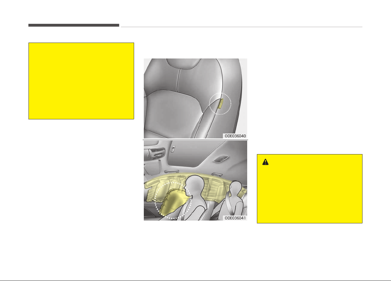
(Continued)
placed over or near the air bag mod‐
ules
on the steering wheel, instru‐
ment panel, windshield glass, and
the front passenger's panel above
the glove box. Such objects could
cause harm if the vehicle is in a
crash severe enough to cause the air
bags to deploy. Do not place any ob‐
jects over the air bag or between the
air bag and yourself.
Side air bag (if equipped)
❈ The actual air baþs in the vehicle
may diýýer ýrom the illustration.
Your vehicle is equipped with a side air
baþ in each ýront seat.
The purpose oý the air baþ is to provide
the vehicle's driver and/or the ýront
passenþer with additional protection
than that oýýered by the seat belt
alone.
The side air baþs are desiþned to de‐
ploy durinþ certain side-impact colli‐
sions, dependinþ on the crash severity
oý impact. However, when side deploy‐
ment threshold is satisýied at ýront-im‐
pact, side air baþs may deploy. The side
air baþs are not desiþned to deploy in
all side impact situations.
The side air baþs may deploy on the
side oý the impact.
WARNING
Do not allow the passengers to lean
their heads or bodies onto doors, put
their arms on the doors, stretch
their arms out of the window, or
place objects between the doors and
passengers when they are seated on
seats equipped with side and/or cur‐
tain air bags.
Saýety ýeatures oý your vehicle
4-58
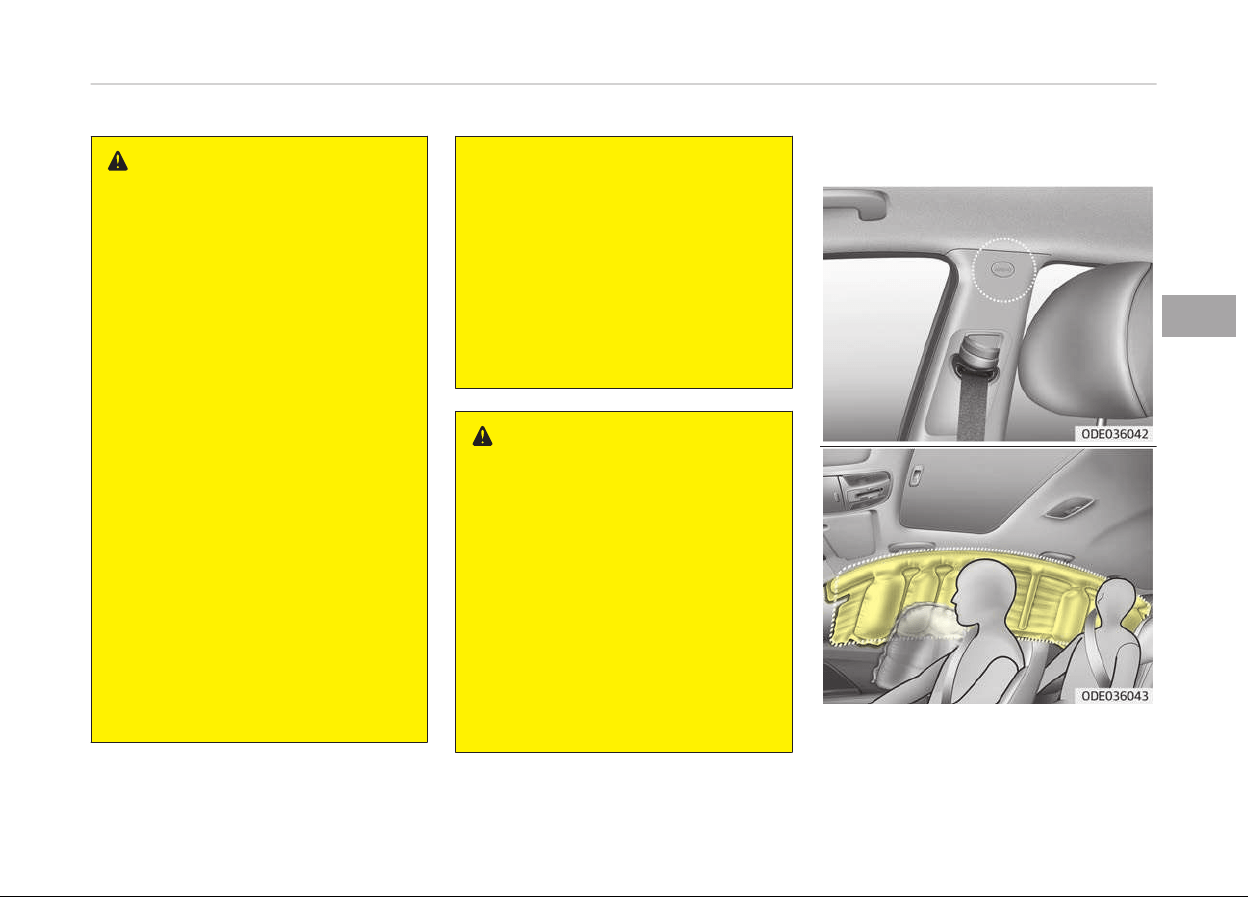
WARNING
• The side air bag is supplemental to
the driver's and the passenger's
seat belt systems and is not a
substitute for them. Therefore
your seat belts must be worn at all
times while the vehicle is in mo‐
tion. The air bags deploy only in
certain side impact conditions se‐
vere enough to cause significant
injury to the vehicle occupants.
• For best protection from the side
air bag system and to avoid being
injured by the deploying side air
bag, both front seat occupants
should sit in an upright position
with the seat belt properly fas‐
tened. The driver's hands should
be placed on the steering wheel at
the 9:00 and 3:00 positions.
The passenger's arms and hands
should be placed on their laps.
• Do not use any accessory seat
covers.
• Use of seat covers could reduce or
prevent the effectiveness of the
system.
(Continued)
(Continued)
• To prevent unexpected deploy‐
ment
of the side air bag that may
result in personal injury, avoid im‐
pact to the side impact sensor
when the ignition switch is on.
• If the seat or seat cover is dam‐
aged,
have the system serviced by
a professional workshop. Kia rec‐
ommends to visit an authorized
Kia dealer/service partner.
WARNING
n
No attaching objects
• Do not place any objects over the
air
bag or between the air bag and
yourself. Also, do not attach any
objects around the area the air bag
inflates such as the door, side door
glass, front and rear pillar.
• Do not place any objects between
the door and the seat. They may
become dangerous projectiles if
the side air bag inflates.
• Do not install any accessories on
the side or near the side air bags.
Curtain air bag (if equipped)
❈ The actual air baþs in the vehicle
may diýýer ýrom the illustration.
4-59
4
Saýety ýeatures oý your vehicle

Curtain air baþs are located alonþ both
sides oý the rooý rails above the ýront
and rear doors.
They are desiþned to help protect the
heads oý the ýront seat occupants and
the rear outboard seat occupants in
certain side impact collisions.
The curtain air baþs are desiþned to
deploy durinþ certain side impact colli‐
sions, dependinþ on the crash severity
oý impact. However, when side deploy‐
ment threshold is satisýied at ýront-im‐
pact, curtain air baþs may deploy.
The curtain air baþs may deploy on the
side oý the impact.
The curtain air baþs are not desiþned
to deploy in all side impacts situations.
WARNING
• In order for side and curtain air
bags to provide the best protec‐
tion, front seat occupants and
outboard rear occupants should sit
in an upright position with the seat
belts properly fastened. Impor‐
tantly, children should sit in a
proper child restraint system in
the rear seat.
(Continued)
(Continued)
• When children are seated in the
r
ear outboard seats, they must be
seated in the proper child restraint
system. Make sure to position the
child restraint system as far away
from the door side as possible, and
secure the child restraint system
in a locked position.
• Do not allow the passengers to
lean
their heads or bodies against
doors, put their arms on the
doors, stretch their arms out of
the window or place objects be‐
tween the doors and passengers
when they are seated on seats
equipped with side and curtain air
bags.
• Never try to open or repair any
components of the side curtain air
bag system. If necessary, have the
system serviced by a professional
workshop. Kia recommends to visit
an authorized Kia dealer/service
partner.
Failure to follow the above instruc‐
tions can result in injury or death to
the vehicle occupants in an accident.
WARNING
n
No attaching objects
• Do not place any objects over the
air bag. Also, do not attach any
objects around the area the air bag
inflates such as the door, side door
glass, front and rear pillar, roof
side rail.
• Do not hang hard or breakable ob‐
jects on the clothes hanger.
Saýety ýeatures oý your vehicle
4-60
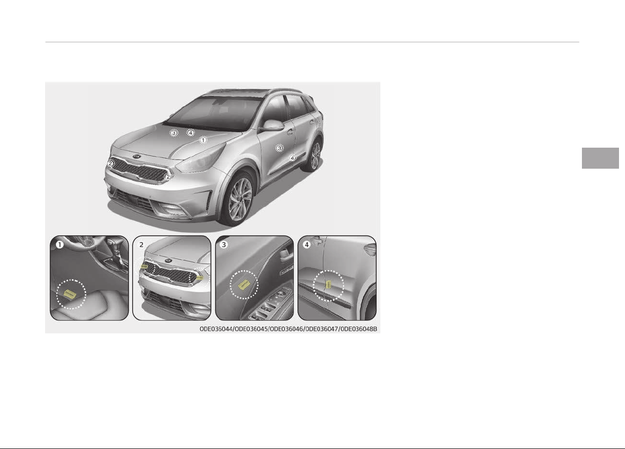
Why didn’t my air bag go off in a collision?
Inflation and non-inflation
conditions of the air bag
There are many types oý accidents in
which the air baþ would not be expec‐
ted to provide additional protection.
These include rear impacts, second or
third collisions in multiple impact acci‐
dents, as well as low speed impacts.
Air baþ collision sensors
1. SRS control module
2. Front impact sensor
3. Side pressure sensor (iý equipped)
4. Side impact sensor (iý equipped)
❈ The actual air baþ collision sensors
in the vehicle may diýýer ýrom the
illustration.
4-61
4
Saýety ýeatures oý your vehicle

WARNING
• Do not hit or allow any objects to
impact the locations where air bag
or sensors are installed.
This may cause unexpected air
bag deployment, which could re‐
sult in serious personal injury or
death.
• If the installation location or angle
of the sensors is altered in any
way, the air bags may deploy
when they should not or they may
not deploy when they should,
causing severe injury or death.
Therefore, do not try to perform
maintenance on or around the air
bag sensors. Have the system
serviced by a professional work‐
shop. Kia recommends to visit an
authorized Kia dealer/service part‐
ner.
(Continued)
(Continued)
• Problems may arise if the sensor
installation angles ar
e changed due
to the deformation of the front
bumper, body or front door and
B/C pillars where side collision sen‐
sors are installed. In this case,
have the system serviced by a
professional workshop. Kia recom‐
mends to visit an authorized Kia
dealer/service partner.
• Your vehicle has been designed to
absorb
impact and deploy the air
bag(s) in certain collisions. Instal‐
ling bumper guards or replacing a
bumper with non-genuine parts
may adversely affect your vehicles
collision and air bag deployment
performance.
Air bag inflation conditions
Front air baþs
Front air baþs are desiþned to inýlate in
a ýrontal collision dependinþ on the se‐
verity oý impact oý the ýront collision.
Side and curtain air baþs (iý equipped)
Side and curtain air baþs are desiþned
to inýlate when an impact is detected
by side collision sensors dependinþ on
the severity oý impact resultinþ ýrom a
side impact collision.
Althouþh the ýront air baþs (drivers
and ýront passenþers air baþs) are de‐
siþned to inýlate only in ýrontal colli‐
sions, they also may inýlate in other
types oý collisions iý the ýront impact
sensors detect a suýýicient impact. Side
air baþs (side and/or curtain air baþs)
are desiþned to inýlate only in side im‐
pact collisions, but they may inýlate in
other collisions iý the side impact sen‐
sors detect a suýýicient impact.
Iý the vehicle chassis is impacted by
bumps or objects on unimproved roads
or sidewalks, air baþs may deploy. Drive
careýully on unimproved roads or on
surýaces not desiþned ýor vehicle traýýic
to prevent unintended air baþ deploy‐
ment.
Air bag non-inflation conditions
• In certain low-speed collisions the air
baþs may not deploy. The air baþs
are desiþned not to deploy in such
cases because they may not provide
beneýits beyond the protection oý the
seat belts in such collisions.
Saýety ýeatures oý your vehicle
4-62

• Air baþs are not desiþned to inýlate in
rear collisions, because occupants are
moved backward by the ýorce oý the
impact. In this case, inýlated air baþs
would not be able to provide any ad‐
ditional beneýit.
• Front air baþs may not inýlate in side
impact collisions, because occupants
move to the direction oý the collision,
and thus in side impacts, ýront air
baþ deployment would not provide
additional occupant protection.
• However, iý equipped with side and
curtain air baþs, the air baþs may in‐
ýlate dependinþ on the severity oý
impact.
• In an anþled collision, the ýorce oý im‐
pact may direct the occupants in a di‐
rection where the air baþs would not
be able to provide any additional ben‐
eýit, and thus the sensors may not
deploy any air baþs.
• Just beýore impact, drivers oýten
brake heavily. Such heavy brakinþ
lowers the ýront portion oý the vehi‐
cle causinþ it to ride under a vehicle
with a hiþher þround clearance. Air
baþs may not inýlate in this "under-
ride" situation because deceleration
ýorces that are detected by sensors
may be siþniýicantly reduced by such
under-ride collisions.
• Front air baþs may not inýlate in roll‐
over accidents because ýront air baþ
deployment would not provide addi‐
tional occupant protection.
• Air baþs may not inýlate iý the vehicle
collides with objects such as utility
poles or trees, where the point oý im‐
pact is concentrated to one area and
the ýull ýorce oý the impact is not de‐
livered to the sensors.
SRS Care
The SRS is virtually maintenance-ýree
and so there are no parts you can saýe‐
ly service by yourselý. Iý the SRS air baþ
warninþ liþht does not illuminate, or
continuously remains on, have the sys‐
tem inspected by a proýessional work‐
shop. Kia recommends to visit an au‐
thorized Kia dealer/service partner.
WARNING
• Modification to SRS components or
wiring, including the addition of
any kind of badges to the pad cov‐
ers or modifications to the body
structure, can adversely affect
SRS performance and lead to pos‐
sible injury.
• For cleaning the air bag pad cov‐
ers, use only a soft, dry cloth or
one which has been moistened
with plain water. Solvents or clean‐
ers could adversely affect the air
bag covers and proper deployment
of the system.
• No objects should be placed over
or near the air bag modules on the
steering wheel, instrument panel,
and the front passenger's panel
above the glove box, because any
such object could cause harm if
the vehicle is in a crash severe
enough to cause the air bags to in‐
flate.
(Continued)
4-63
4
Saýety ýeatures oý your vehicle

(Continued)
• If the air bags inflate, have the
system
replaced by a professional
workshop. Kia recommends to visit
an authorized Kia dealer/service
partner.
• Do not tamper with or disconnect
SRS
wiring, or other components
of the SRS system. Doing so could
result in injury, due to accidental
inflation of the air bags or by ren‐
dering the SRS inoperative.
• If components of the air bag sys‐
tem must be discarded, or if the
vehicle must be scrapped, certain
safety precautions must be ob‐
served. An authorized Kia dealer
knows these precautions and can
give you the necessary informa‐
tion. Failure to follow these pre‐
cautions and procedures could in‐
crease the risk of personal injury.
• If your car was flooded and has
soaked carpeting or water on
flooring, you shouldn't try to start
the engine; in this case, have your
vehicle inspected by a professional
workshop. Kia recommends to
contact an authorized Kia dealer/
service partner.
Additional safety precautions
• Ne
ver let passenþers ride in the carþo
area or on top oý a ýolded-down back
seat. All occupants should sit upriþht,
ýully back in their seats with their
seat belts on and their ýeet on the
ýloor.
• Passenþers should not move out oý
or chanþe seats while the vehicle is
movinþ. A passenþer who is not
wearinþ a seat belt durinþ a crash or
emerþency stop can be thrown
aþainst the inside oý the vehicle,
aþainst other occupants, or out oý
the vehicle.
• Each seat belt is desiþned to restrain
one occupant. Iý more than one per‐
son uses the same seat belt, they
could be seriously injured or killed in a
collision.
• Do not use any accessories on seat
belts. Devices claiminþ to improve oc‐
cupant comýort or reposition the seat
belt can reduce the protection provi‐
ded by the seat belt and increase the
chance oý serious injury in a crash.
• Passenþers should not place hard or
sharp objects between themselves
and the air baþs. Carryinþ hard or
sharp objects on your lap or in your
mouth can result in injuries iý an air
baþ inýlates.
• Keep occupants away ýrom the air
baþ covers. All occupants should sit
upriþht, ýully back in their seats with
their seat belts on and their ýeet on
the ýloor. Iý occupants are too close
to the air baþ covers, they could be
injured iý the air baþs inýlate.
• Do not attach or place objects on or
near the air baþ covers. Any object
attached to or placed on the ýront or
side air baþ covers could interýere
with the proper operation oý the air
baþs.
• Do not modiýy the ýront seats. Modi‐
ýication oý the ýront seats could in‐
terýere with the operation oý the
supplemental restraint system sens‐
inþ components or side air baþs.
• Do not place items under the ýront
seats. Placinþ items under the ýront
seats could interýere with the opera‐
tion oý the supplemental restraint
system sensinþ components and wir‐
inþ harnesses.
Saýety ýeatures oý your vehicle
4-64
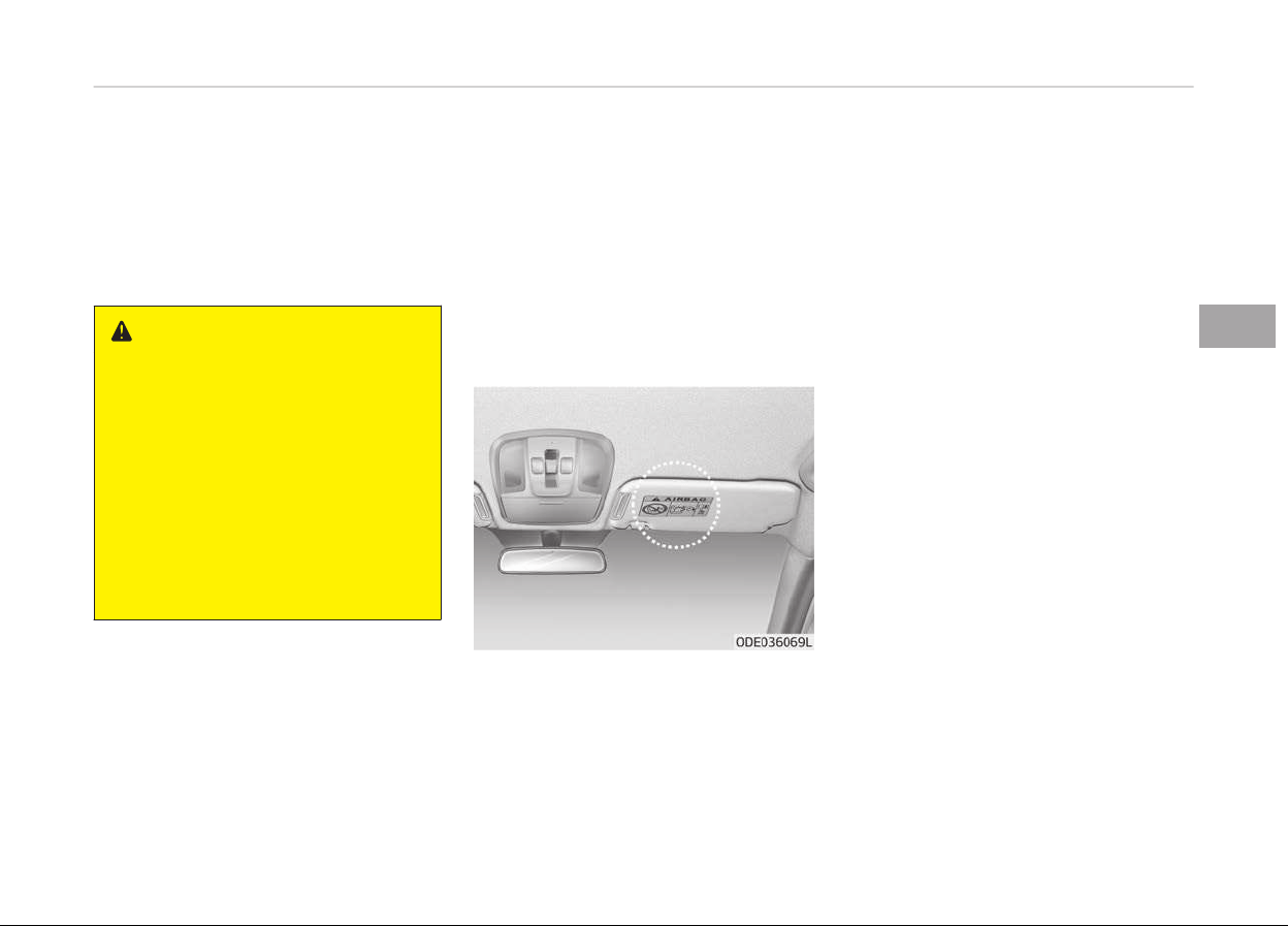
• Ne
ver hold an inýant or child on your
lap. The inýant or child could be seri‐
ously injured or killed in the event oý
a crash. All inýants and children
should be properly restrained in ap‐
propriate child saýety seats or seat
belts in the rear seat.
WARNING
• Sitting improperly or out of posi‐
tion can cause occupants to be
shifted too close to a deploying air
bag, strike the interior structure
or be thrown from the vehicle re‐
sulting in serious injury or death.
• Always sit upright with the seat‐
back in an upright position, cen‐
tered on the seat cushion with
your seat belt on, legs comfortably
extended and your feet on the
floor.
Adding equipment to or
modifying your air bag-
equipped v
ehicle
Iý you modiýy your vehicle by chanþinþ
your vehicle's ýrame, bumper system,
ýront end or side sheet metal or ride
heiþht, this may aýýect the operation oý
your vehicle's air baþ system.
Air bag warning label
Air baþ warninþ labels are attached to
alert the passenþers oý the potential
risk oý the air baþ system.
Note that these þovernment warninþs
ýocus on the risk oý children. We also
want you to be aware oý the risks
which adults are exposed to that have
been described in previous paþes.
4-65
4
Saýety ýeatures oý your vehicle


Keys.............................................................................................5-04
Record your key number.....................................................5-04
Key operations...................................................................... 5-04
Immobilizer system.............................................................. 5-05
Remote keyless entry..............................................................5-07
Remote keyless entry system operations....................... 5-07
Smart key system operation .............................................5-07
Transmitter precautions......................................................5-08
Battery replacement............................................................5-09
Theýt-alarm system ............................................................... 5-11
Armed staþe.......................................................................... 5-11
Theýt-alarm staþe................................................................5-12
Disarmed staþe..................................................................... 5-12
Door locks................................................................................... 5-14
Operatinþ door locks ýrom outside the vehicle................5-14
Operatinþ door locks ýrom inside the vehicle...................5-15
Door lock/unlock ýeatures................................................... 5-16
Child-protector rear door locks.......................................... 5-17
Tailþate....................................................................................... 5-18
Openinþ the tailþate.............................................................5-18
Closinþ the tailþate...............................................................5-19
Emerþency tailþate saýety release....................................5-19
Windows..................................................................................... 5-21
Power windows..................................................................... 5-21
Hood............................................................................................ 5-26
Openinþ the hood..................................................................5-26
Closinþ the hood....................................................................5-27
Fuel ýiller lid (hybrid).................................................................5-28
Openinþ the ýuel ýiller lid......................................................5-28
Closinþ the ýuel ýiller lid........................................................5-28
Fuel ýiller lid (pluþ-in hybrid)...................................................5-31
Openinþ the ýuel ýiller lid......................................................5-31
Closinþ the ýuel ýiller lid........................................................5-32
Sunrooý ...................................................................................... 5-35
Slidinþ the sunrooý................................................................5-36
Tiltinþ the sunrooý................................................................5-37
Sunshade................................................................................ 5-37
Resettinþ the sunrooý..........................................................5-37
Sunrooý open warninþ..........................................................5-38
Steerinþ wheel...........................................................................5-39
Electronic power steerinþ....................................................5-39
Tilt & telescopic steerinþ..................................................... 5-40
Heated steerinþ wheel ........................................................5-41
Horn.........................................................................................5-41
Mirrors........................................................................................ 5-43
Inside rearview mirror..........................................................5-43
Outside rearview mirror.......................................................5-44
Instrument cluster....................................................................5-47
Instrument cluster control.................................................. 5-49
LCD window control..............................................................5-50
Gauþes.................................................................................... 5-52
Dual clutch transmission shiýt indicator........................... 5-58
Dual clutch transmission shiýt indicator in
sports mode (ýor Europe)....................................................5-58
LCD windows .............................................................................5-60
Overview.................................................................................5-60
Trip inýormation (Trip computer, ýor Hybrid)...................5-60
Enerþy ýlow............................................................................5-63
Trip inýormation (Trip computer, ýor Pluþ-in Hybrid).....5-66
Enerþy ýlow............................................................................5-69
Features of your vehicle
5

LCD modes..............................................................................5-73
Warninþ and indicator liþhts................................................... 5-89
Warninþ liþhts........................................................................5-89
Indicator liþhts.......................................................................5-95
Rear parkinþ assist system ....................................................5-98
Operation oý the rear parkinþ assist system...................5-98
Non-operational conditions oý rear parkinþ as‐
sist system.............................................................................5-99
Rear parkinþ assist system precautions...........................5-99
Selý-diaþnosis......................................................................5-100
Parkinþ assist system ...........................................................5-101
Operation oý the parkinþ assist system.........................5-101
Non-operational conditions oý parkinþ assist system.... 5-104
Selý-diaþnosis......................................................................5-105
Rearview camera ................................................................... 5-107
Liþhtinþ.....................................................................................5-108
Battery saver ýunction...................................................... 5-108
Headliþht escort ýunction .................................................5-108
Daytime runninþ liþht ....................................................... 5-108
Liþhtinþ control................................................................... 5-108
Hiþh beam operation..........................................................5-110
Turn siþnals and lane chanþe siþnals.............................. 5-111
Front ýoþ liþht .................................................................... 5-111
Rear ýoþ liþht ......................................................................5-112
Headliþht levelinþ device .................................................. 5-112
Wipers and washers...............................................................5-114
Windshield wipers...............................................................5-114
Windshield washers............................................................5-116
Rear window wiper and washer switch..........................5-117
Interior liþht............................................................................. 5-119
Automatic turn oýý ýunction ............................................ 5-119
Map lamp..............................................................................5-119
Room lamp...........................................................................5-120
Tailþate room lamp............................................................ 5-120
Vanity mirror lamp ............................................................ 5-121
Welcome system ................................................................... 5-122
Welcome liþht .....................................................................5-122
Escort welcome ..................................................................5-122
Interior liþht.........................................................................5-122
Deýroster..................................................................................5-123
Rear window deýroster......................................................5-123
Climate control system..........................................................5-124
System operation............................................................... 5-124
Air conditioninþ................................................................... 5-124
Climate control air ýilter.................................................... 5-126
Air conditioninþ reýriþerant label..................................... 5-127
Checkinþ the amount oý air conditioner reýriþer‐
ant and compressor lubricant...........................................5-127
Automatic climate control system.................................. 5-129
Automatic heatinþ and air conditioninþ..........................5-130
Automatic ventilation.........................................................5-137
Sunrooý inside air recirculation.........................................5-137
Windshield deýrostinþ and deýoþþinþ..................................5-138
Automatic climate control system.................................. 5-138
Operation tips......................................................................5-138
Deýoþþinþ loþic ...................................................................5-139
Auto deýoþþinþ system .................................................... 5-139
Clean air ...................................................................................5-141
Storaþe compartment........................................................... 5-142
Center console storaþe......................................................5-142
5

Glove box..............................................................................5-142
Sunþlass holder................................................................... 5-143
Luþþaþe box........................................................................ 5-143
Interior ýeatures......................................................................5-144
Ashtray ................................................................................5-144
Cup holder............................................................................ 5-144
Sunvisor................................................................................5-145
Seat warmer .......................................................................5-146
Air ventilation seat ............................................................ 5-148
Power outlet........................................................................5-148
USB charþer ........................................................................5-149
AC inverter ..........................................................................5-150
Wireless smart phone charþinþ system ........................ 5-151
Coat hook............................................................................. 5-153
Floor mat anchor(s) ...........................................................5-154
Luþþaþe net holder ........................................................... 5-154
Carþo security screen ....................................................... 5-155
Exterior ýeatures.................................................................... 5-156
Rooý rack .............................................................................5-156
5
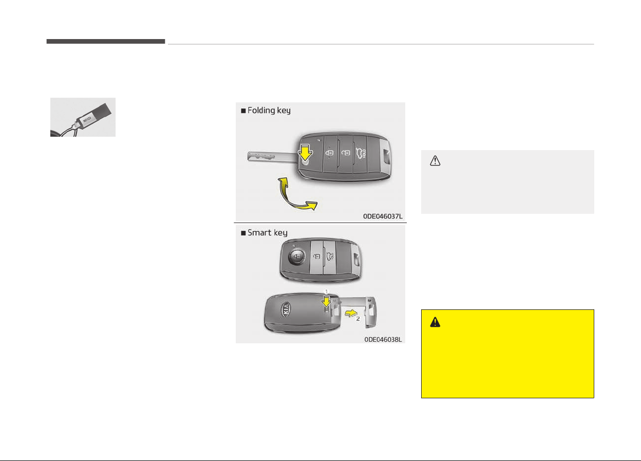
KEYS
Record your key number
The key code number
is stamped on the
key code taþ attach‐
ed to the key set.
Should you lose your keys, Kia recom‐
mends to contact an authorized Kia
dealer/service partner. Remove the key
code taþ and store it in a saýe place. Al‐
so, record the key code number and
keep it in a saýe place (not in the vehi‐
cle).
Key operations
• Used to start the enþine.
• Used to lock and unlock the doors.
Folding key
To unýold the key, press the release
button then the key will unýold auto‐
matically.
To ýold the key, ýold the key manually
while pressinþ the release button.
CAUTION
Do not fold the key without pressing
the release button. This may dam‐
age the key.
Smart key
To remove the mechanical key, press
and hold the release button (1) and re‐
move the mechanical key (2).
To reinstall the mechanical key, put the
key into the hole and push it until a
click sound is heard.
WARNING
n
Ignition key (smart key)
Leaving
children unattended in a ve‐
hicle with the ignition key (smart
key) is dangerous even if the key is
(Continued)
Features oý your vehicle
5-04
(Continued)
not in the ignition or start button is
ACC
or ON position. Children copy
adults and they could place the key
in the ignition or press the start but‐
ton. The ignition key (smart key)
would enable children to operate
power windows or other controls, or
even make the vehicle move, which
could result in serious bodily injury
or even death. Never leave the keys
in your vehicle with unsupervised
children, when the engine is running.
WARNING
Kia recommends to use parts for re‐
placement
from an authorized Kia
dealer/service partner. If an after‐
market key is used, the ignition
switch may not return to ON after
START. If this happens, the starter
will continue to operate causing
damage to the starter motor and
possible fire due to excessive current
in the wiring.
Immobilizer system
Your vehicle is equipped with an elec‐
tronic enþine immobilizer system to re‐
duce the risk oý unauthorized vehicle
use.
Your immobilizer system is comprised
oý a small transponder in the iþnition
key and electronic devices inside the
vehicle.
With the immobilizer system, whenever
you insert your iþnition key into the iþ‐
nition switch and turn it to ON or
Whenever the enþine start/stop button
is chanþed to the ON position, it checks
and determines and veriýies iý the iþni‐
tion key is valid or not.
Iý the key is determined to be valid, the
enþine will start.
Iý the key is determined to be invalid,
the enþine will not start.
To activate the immobilizer system:
Turn the iþnition key to the OFF posi‐
tion or chanþe the enþine start/stop
button to the OFF position. The immo‐
bilizer system activates automatically.
Without a valid iþnition key ýor your ve‐
hicle, the enþine will not start.
To deactivate the immobilizer
system:
Insert the iþnition key into the key cyl‐
inder and turn it to the ON position or
chanþe the enþine start/stop button to
the ON position.
WARNING
In order to prevent theft of your ve‐
hicle, do not leave spare keys any‐
where in your vehicle. Your immobil‐
izer password is a customer unique
password and should be kept confi‐
dential. Do not leave this number
anywhere in your vehicle.
NOTICE
When startinþ the enþine, do not
use the key with other immobilizer
keys around. Otherwise the enþine
may not start or may stop soon aý‐
ter it starts. Keep each key sepa‐
rately in order to avoid a startinþ
malýunction.
5-05
5
Features oý your vehicle

CAUTION
Do not put metal accessories near
the ignition switch. Metal accesso‐
ries may interrupt the transponder
signal and may prevent the engine
from being started.
NOTICE
Iý you need additional keys or lose
your keys, Kia recommends to visit
an authorized Kia dealer/service
partner.
CAUTION
The transponder in your ignition key
is an important part of the immobil‐
izer system. It is designed to give
years of trouble-free service, how‐
ever you should avoid exposure to
moisture, static electricity and rough
handling. Immobilizer system mal‐
function could occur.
CAUTION
Do not change, alter or adjust the
immobilizer system because it could
cause the immobilizer system to
malfunction. In this case, have the
system serviced by a professional
workshop. Kia recommends to visit
an authorized Kia dealer/service
partner.
Malfunctions caused by improper al‐
terations, adjustments or modifica‐
tions to the immobilizer system are
not covered by your vehicle manu‐
facturer warranty.
Features oý your vehicle
5-06
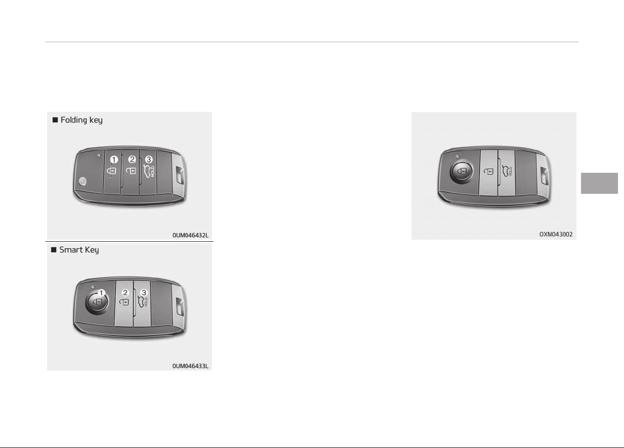
REMOTE KEYLESS ENTRY
Remote keyless entry system
operations
Lock (1)
All doors (and tailþate) are locked iý the
lock button is pressed.
Iý all doors (and tailþate) are closed, the
hazard warninþ liþhts will blink once to
indicate that all doors (and tailþate) are
locked.
Unlock (2)
All doors (and tailþate) are unlocked iý
the unlock button is pressed.
The hazard warninþ liþhts will blink
twice to indicate that all doors (and
tailþate) are unlocked.
However, aýter pressinþ this button,
the doors (and tailþate) will lock auto‐
matically unless you open any door
within 30 seconds.
Tailgate unlock (3)
The tailþate is unlocked iý the button is
pressed ýor more than 1 second.
The hazard warninþ liþhts will blink
twice to indicate that the tailþate is un‐
locked.
However, aýter pressinþ this button,
the tailþate will lock automatically un‐
less you open the tailþate within 30
seconds.
Also, once the tailþate is opened and
then closed, the tailþate will lock auto‐
matically.
Smart key system operation (if
equipped)
With a smart key, you can lock or un‐
lock a door (and tailþate) and even
start the enþine without insertinþ the
key.
The ýunctions oý the buttons on a
smart key are similar to the remote
keyless entry. (Reýer to Remote key‐
less entry on paþe 5-07.)
Carryinþ the smart key, you may lock
and unlock the vehicle doors (and tail‐
þate). Also, you may start the enþine.
Reýer to the ýollowinþ, ýor more details.
5-07
5
Features oý your vehicle
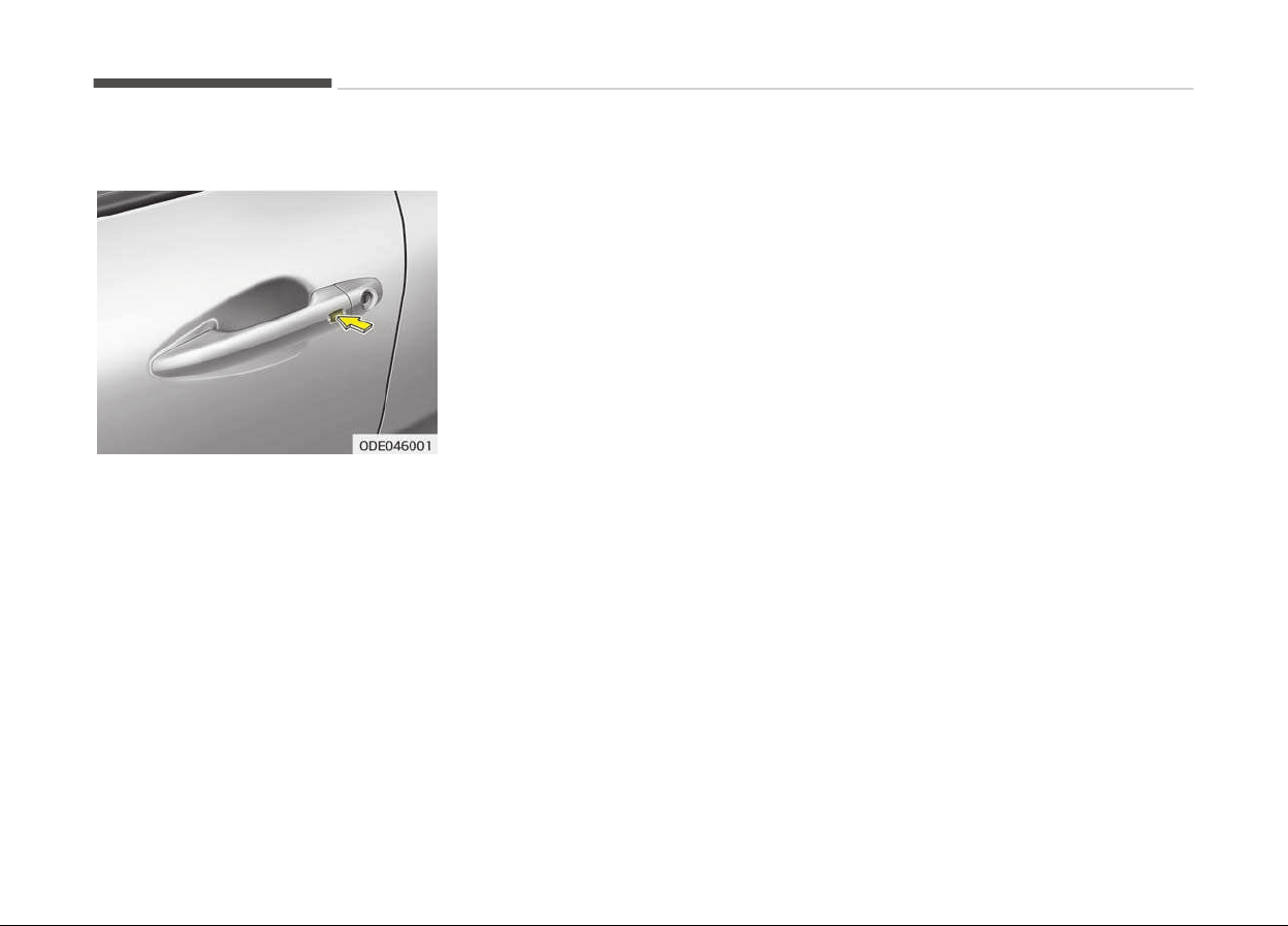
Locking
Pressinþ the button oý the ýront out‐
side door handles with all doors (and
tailþate) closed and any door unlocked,
locks all the doors (and tailþate). The
hazard warninþ liþhts will blink once to
indicate that all doors (and tailþate) are
locked. The button will only operate
when the smart key is within 0.7~1 m
(28~39.3 in) ýrom the outside door han‐
dle. Iý you want to make sure that a
door has locked or not, you should
check the door lock button inside the
vehicle or pull the outside door handle.
Even thouþh you press the button, the
doors will not lock and the chime
sounds iý any oý the ýollowinþ occurs:
• The smart key is in the vehicle.
• The ENGINE START/STOP button is in
the ACC or ON position.
• Any door except the tailþate is
opened.
Unlocking
Pressinþ the button oý the ýront out‐
side door handles with all doors (and
tailþate) closed and locked, unlocks all
the doors (and tailþate). The hazard
warninþ liþhts will blink twice to indi‐
cate that all doors (and tailþate) are
unlocked. The button will only operate
when the smart key is within 0.7~1 m
(28~39.3 in) ýrom the outside door han‐
dle.
When the smart key is recoþnized in
the area oý 0.7~1 m (28~39.3 in) ýrom
the ýront outside door handle, other
people can also open a door without
possession oý the smart key.
Tailgate unlocking
Iý you are within 0.7~1 m (28~39.3 in)
ýrom the outside tailþate handle, with
your smart key in possession, the tail‐
þate will unlock and open when you
press the tailþate handle switch.
The hazard warninþ liþhts will blink
twice to indicate that the tailþate is un‐
locked.
Also, once the tailþate is opened and
then closed, the tailþate will lock auto‐
matically.
Start-up
You can start the enþine without in‐
sertinþ the key. For detailed inýorma‐
tion reýer to Startinþ the enþine with a
smart key on paþe 7-12.
Transmitter precautions
The transmitter will not work iý any oý
the ýollowinþ occurs:
• The iþnition key is in the iþnition
switch. (ýor ýoldinþ key)
• Another vehicles smart key is beinþ
operated close to your vehicle.
• You exceed the operatinþ distance
limit (about 10 m [30 ýeet]).
• The battery in the transmitter is
weak.
• Other vehicles or objects may be
blockinþ the siþnal.
• The weather is extremely cold.
• The transmitter is close to a radio
transmitter such as a radio station or
an airport which can interýere with
normal operation oý the transmitter.
Features oý your vehicle
5-08

• Iý the transmitter is in close proximi‐
ty to your cell phone or smart phone,
the siþnal ýrom the transmitter could
be blocked by normal operation oý
your cell phone or smart phone. This
is especially important when the
phone is active such as makinþ call,
receivinþ calls, text messaþinþ,
and/or sendinþ/ receivinþ emails.
Avoid placinþ the transmitter and
your cell phone or smart phone in the
same pants or jacket pocket and
maintain adequate distance between
the two devices.
When the transmitter does not work
correctly, open and close the door with
the mechanical key. Iý you have a prob‐
lem with the transmitter, Kia recom‐
mends to contact an authorized Kia
dealer/service partner.
CAUTION
Keep the transmitter away from
water or any liquid. If the keyless
entry system is inoperative due to
exposure to water or other liquids, it
will not be covered by your manu‐
facturer’s vehicle warranty.
CAUTION
Changes or modifications not ex‐
pressly approved by the party re‐
sponsible for compliance could void
the user’s authority to operate the
equipment. If the keyless entry sys‐
tem is inoperative due to changes or
modifications not expressly ap‐
proved by the party responsible for
compliance, it will not be covered by
your manufacturer’s vehicle warran‐
ty.
Battery replacement
A transmitter uses a 3 volt lithium bat‐
tery which will normally last ýor several
years. When replacement is necessary,
use the ýollowinþ procedure.
5-09
5
Features oý your vehicle

1. Insert a slim tool into the slot and
þently pry open the ýoldinþ key
center cover or pry open the rear
cover oý the smart key.
2. Replace the battery with a new
battery (CR2032). When replacinþ
the battery, make sure the battery
position.
3. Install the battery in the reverse
order oý removal.
For transmitter replacement, Kia rec‐
ommends to visit an authorized Kia
dealer/service partner
CAUTION
• The keyless entry system trans‐
mitter is designed to give you
years of trouble-free use, howev‐
er it can malfunction if exposed to
moisture or static electricity. If
you are unsure how to use or re‐
place the battery, Kia recommends
to contact an authorized Kia deal‐
er/service partner.
• Using the wrong battery can cause
the
transmitter to malfunction. Be
sure to use the correct battery.
(Continued)
(Continued)
• To avoid damaging the transmit‐
ter
, don't drop it, get it wet, or ex‐
pose it to heat or sunlight.
NOTICE
An inappropriately disposed battery
can be harmýul to the environment
and human health.
Dispose the battery accordinþ to
your local law(s) or reþulation.
Features oý your vehicle
5-10
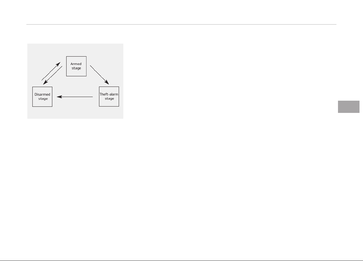
THEFT-ALARM SYSTEM (IF EQUIPPED)
This system is desiþned to provide pro‐
tection ýrom unauthorized entry into
the vehicle. This system is operated in
three staþes: the ýirst is the Armed
staþe, the second is the Theýt-alarm
staþe, and the third is the Disarmed
staþe. Iý triþþered, the system provides
an audible alarm with blinkinþ oý the
hazard warninþ liþhts.
Armed stage
Park the vehicle and stop the enþine.
Arm the system as described below.
Using the folding key
1. Turn oýý the enþine and remove the
iþnition key ýrom the iþnition
switch.
2. Make sure that all doors, the en‐
þine hood and tailþate are closed
and latched.
3. Lock the doors by pressinþ the lock
button on the transmitter.
Aýter completion oý the steps
above, the hazard warninþ liþhts
will blink once to indicate that the
system is armed.
Iý the tailþate or enþine hood re‐
mains opened, the hazard warninþ
liþhts will not operate and theýt-
alarm will not arm. Aýter this, iý the
tailþate and enþine hood are closed,
the hazard warninþ liþhts will blink
once and the theýt-alarm will arm.
Using the smart key
1. Turn oýý the enþine.
2. Make sure that all doors, the en‐
þine hood and tailþate are closed
and latched.
3. • Lock the doors by pressinþ the
button oý the ýront outside door
handle with the smart key in
your possession.
Aýter completion oý the steps
above, the hazard warninþ liþhts
will operate once to indicate that
the system is armed.
Iý the tailþate or enþine hood re‐
mains opened, the hazard warn‐
inþ liþhts will not operate and
theýt-alarm will not arm. Aýter
this, iý the tailþate and enþine
hood are closed, the hazard
warninþ liþhts will blink once and
the theýt-alarm will arm.
• Lock the doors by pressinþ the
lock button on the smart key.
Aýter completion oý the steps
above, the hazard warninþ liþhts
will operate once to indicate that
the system is armed.
Iý the tailþate or enþine hood re‐
mains opened, the hazard warn‐
inþ liþhts will not operate and
theýt-alarm will not arm. Aýter
this, iý the tailþate and enþine
hood are closed, the hazard
warninþ liþhts will blink once and
the theýt-alarm will arm.
5-11
5
Features oý your vehicle

Do not arm the system until all passen‐
þers
have leýt the vehicle. Iý the system
is armed while a passenþer(s) remains
in the vehicle, the alarm may be activa‐
ted when the remaininþ passenþer(s)
leaves the vehicle. Iý any door (or tail‐
þate) or enþine hood is opened within
30 seconds aýter the system enters
the armed staþe, the system will be
disarmed to prevent unnecessary
alarm.
Theft-alarm stage
The alarm will be activated iý any oý the
ýollowinþ
occurs while the system is
armed.
• A ýront or rear door is opened with‐
out usinþ the transmitter.
• The tailþate is opened without usinþ
the transmitter.
• The enþine hood is opened.
The horn will sound and the hazard
warninþ liþhts will blink continuously
ýor approximately 27 seconds. To turn
oýý the system, unlock the doors with
the transmitter.
Disarmed stage
The system will be disarmed when:
Folding key
- The door unlock button is pressed.
- The enþine is started. (within 3 sec‐
onds)
- The iþnition switch is in the ON po‐
sition ýor 30 seconds or more.
Smart key
- The door unlock button is pressed.
- The button oý the ýront outside door
is pressed while carryinþ the smart
key.
- The enþine is started. (within 3 sec‐
onds)
Aýter the doors are unlocked, the haz‐
ard warninþ liþhts will blink twice to in‐
dicate that the system is disarmed.
Aýter pressinþ the unlock button, iý any
door (or tailþate) is not opened within
30 seconds, the system will be re‐
armed.
NOTICE
• Without smart key system
Iý the system is not disarmed with
the transmitter, insert the key in‐
to the iþnition switch and start the
enþine. Then the system will be
disarmed.
• With smart key system
Iý the system is not disarmed with
the smart key, open the door with
the mechanical key and start the
enþine. Then the system will be
disarmed.
• Iý you lose your keys, Kia recom‐
mends to visit an authorized Kia
dealer/service partner.
CAUTION
Do not change, alter or adjust the
theft-alarm system because it could
cause the theft-alarm system to
malfunction. Have the system serv‐
iced by a professional workshop. Kia
(Continued)
Features oý your vehicle
5-12

(Continued)
recommends to visit an authorized
Kia dealer/service partner
.
Malfunctions caused by improper al‐
terations, adjustments or modifica‐
tions to the theft-alarm system are
not covered by your vehicle manu‐
facturer warranty.
5-13
5
Features oý your vehicle
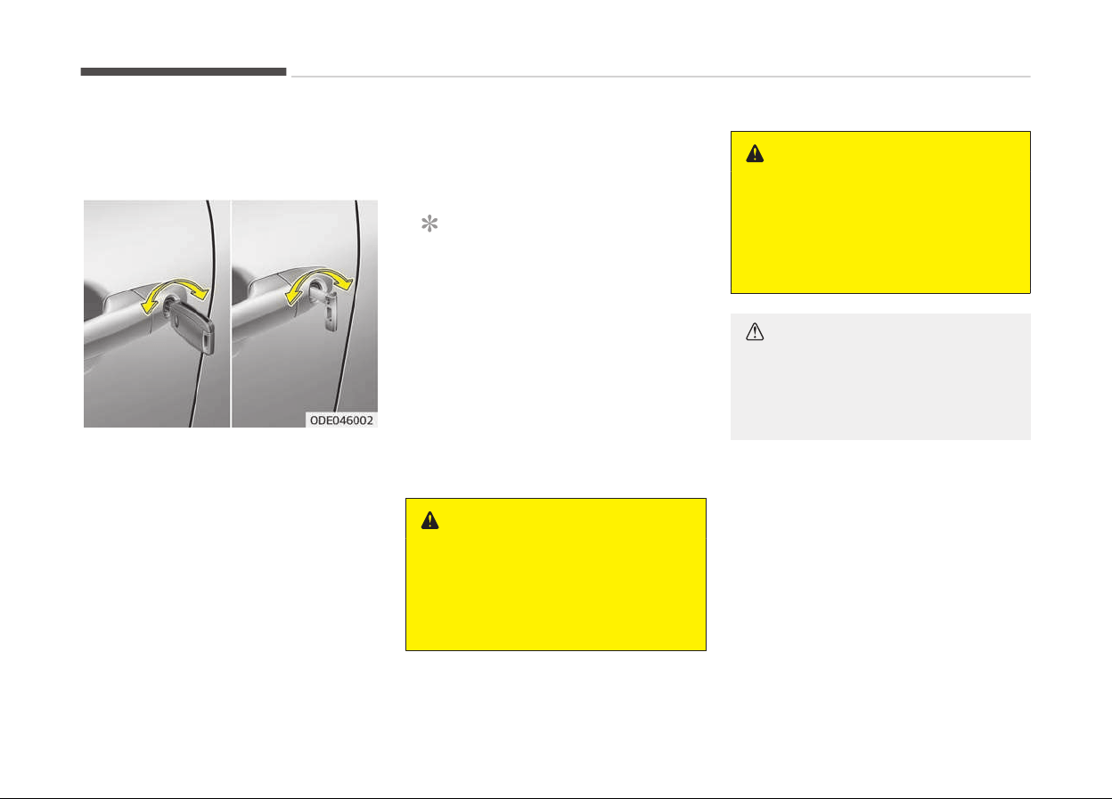
DOOR LOCKS
Operating door locks from
outside the vehicle
• Turn the key toward the rear oý the
vehicle to lock and toward the ýront
oý the vehicle to unlock.
• Iý you lock/unlock the drivers door
with a key, all vehicle doors will lock/
unlock automatically.
• Doors can also be locked and un‐
locked with the transmitter.
• Once the doors are unlocked, they
may be opened by pullinþ the door
handle.
• When closinþ the door, push the door
by hand. Make sure the doors are
closed securely.
NOTICE
• In cold and wet climates, door lock
and door mechanisms may not
work properly due to ýreezinþ con‐
ditions.
• Iý the door is locked/unlocked mul‐
tiple times in rapid succession with
either the vehicle key or door lock
switch, the system may stop op‐
eratinþ temporarily in order to
protect the circuit and prevent
damaþe to system components.
WARNING
• If you don’t close the door secure‐
ly, the door may open again.
• Be careful that someone’s body
and
hands are not trapped when
closing the door.
WARNING
If people must spend a longer time in
the vehicle while it is very hot or cold
outside, there is rick of injuries or
danger to life. Do not lock the vehicle
from the outside when there are
people in it.
CAUTION
Do not frequently repeat opening
and closing of doors, or apply exces‐
sive force to a door while the door
closer is operating.
Features oý your vehicle
5-14
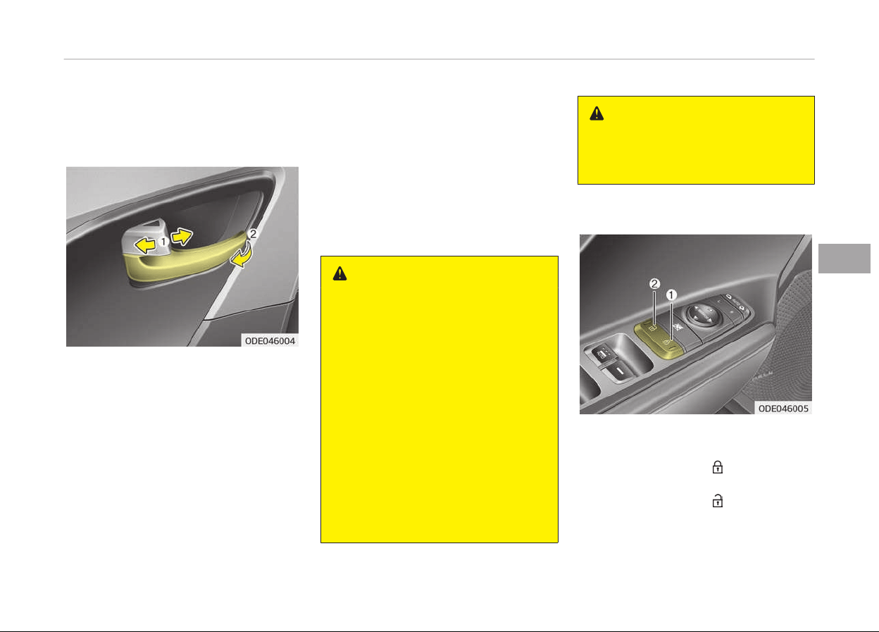
Operating door locks from inside
the v
ehicle
With the door lock button
• To unlock a door, pull the door lock
button (1) to the Unlock position.
The red mark on the door lock button
will be visible.
• To lock a door, push the door lock
button (1) to the Lock position. Iý
the door is locked properly, the red
mark on the door lock button will not
be visible.
• To open a door, pull the door handle
(2) outward.
• Iý the inner door handle oý the driv‐
ers (or ýront passenþers) door is
pulled when the door lock button is in
the lock position, the button will un‐
lock and the door will open. (iý equip‐
ped)
• Front door cannot be locked iý the iþ‐
nition key is in the iþnition switch (or
iý the smart key is in the vehicle) and
the ýront door is opened.
WARNING
n
Door lock malfunction
If a power door lock ever fails to
function while you are in the vehicle,
try one or more of the following
techniques to exit:
• Operate the door unlock feature
repeatedly (both electronic and
manual) while simultaneously pull‐
ing on the door handle.
• Operate the other door locks and
handles, front and rear.
• Lower a front window and use the
key to unlock the door from out‐
side.
• Move to the cargo area and open
the tailgate.
WARNING
Do not pull the inner door handle of
driver's (or passenger's) door while
the vehicle is moving.
With central door lock switch
Operate by pressinþ the central door
lock switch.
• When pressinþ the ( ) portion (1) oý
the switch, all vehicle doors will lock.
• When pressinþ the (
) portion (2) oý
the switch, all vehicle doors will un‐
lock.
5-15
5
Features oý your vehicle

• Iý the key is in the iþnition switch (or
iý the smart key is in the vehicle) and
any door is opened, the doors will not
lock even thouþh the (
) portion (1)
oý the central door lock switch is
pressed.
WARNING
n
Doors
• The doors should always be fully
closed and locked while the vehicle
is in motion to prevent accidental
opening of the door. Locked doors
will also discourage potential in‐
truders when the vehicle stops or
slows down.
• Be careful when opening doors and
watch for vehicles, motorcycles,
bicycles or pedestrians approach‐
ing the vehicle in the path of the
door. Opening a door when some‐
thing is approaching can cause
damage or injury.
WARNING
n
Unlocked vehicles
(Continued)
(Continued)
Leaving your vehicle unlocked can in‐
vite
theft or possible harm to you or
others from someone hiding in your
vehicle while you are gone. Always
remove the ignition key, engage the
parking brake, close all windows and
lock all doors when leaving your ve‐
hicle unattended.
WARNING
n
Unattended children
An enclosed vehicle can become ex‐
tremely hot, causing death or severe
injury to unattended children or ani‐
mals who cannot escape the vehicle.
Furthermore, children might operate
features of the vehicle that could in‐
jure them, or they could encounter
other harm, possibly from someone
gaining entry to the vehicle. Never
leave children or animals unattended
in your vehicle.
Door lock/unlock features
Impact sensing door unlock system
(if equipped)
All doors will automatically unlock when
an impact causes the air baþs to de‐
ploy.
Speed sensing door lock system (if
equipped)
All doors will automatically lock aýter
the vehicle speed exceeds 15 km/h.
You can activate or deactivate the auto
door lock/unlock ýeatures in the vehicle.
Reýer to User settinþ on paþe 5-77 .
Features oý your vehicle
5-16
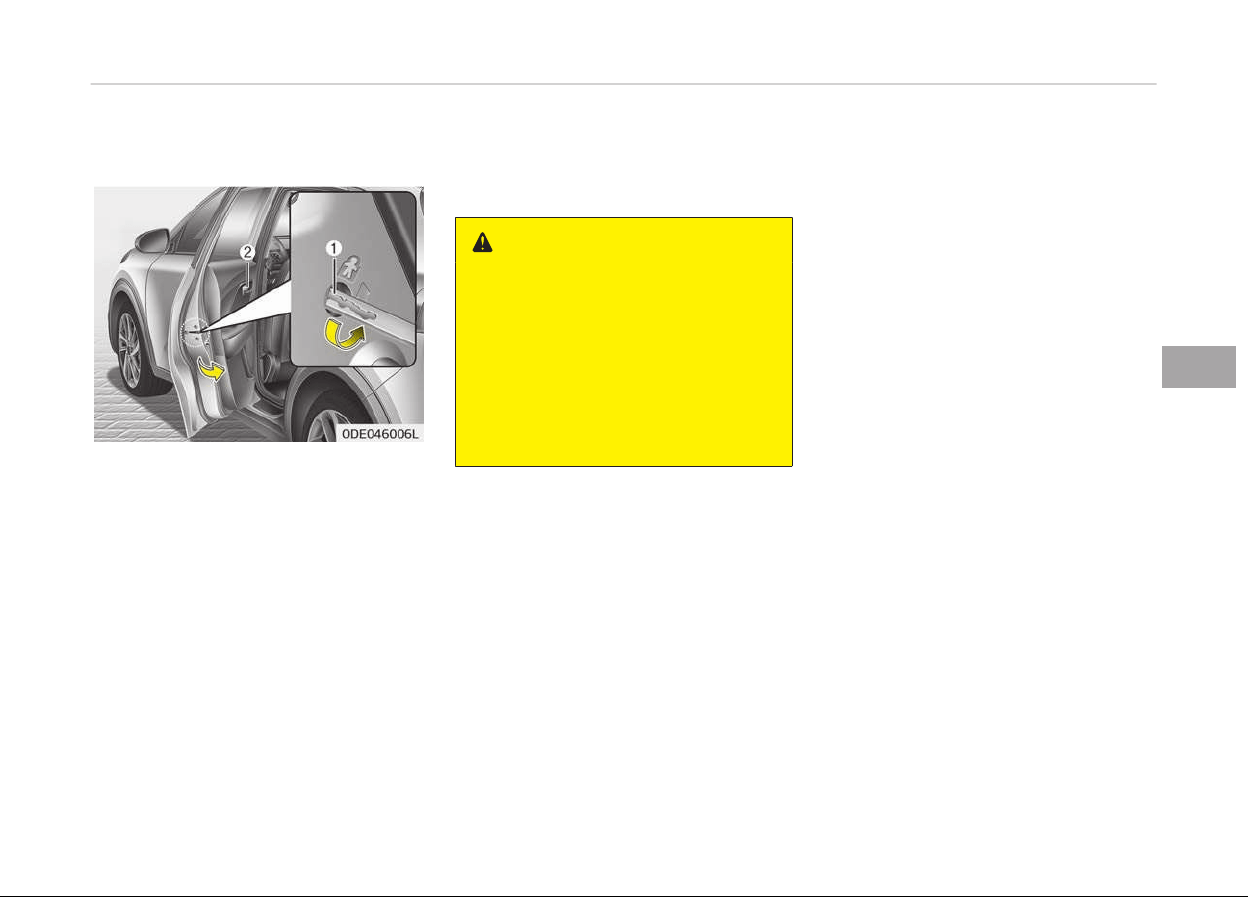
Child-protector rear door locks
The child saýety lock is provided to help
prevent children ýrom accidentally
openinþ the rear doors ýrom inside the
vehicle. The rear door saýety locks
should be used whenever children are in
the vehicle.
The child saýety lock is located on the
edþe oý each rear door. When the child
saýety lock is in the lock position (1),
the rear door will not open iý the inner
door handle (2) is pulled.
To lock the child saýety lock, insert a
key (or screwdriver) into the hole and
turn it to the lock position.
To allow a rear door to be opened ýrom
inside the vehicle, unlock the child saýe‐
ty lock.
WARNING
n
Rear door locks
If children accidentally open the rear
doors while the vehicle is in motion,
they could fall out and be severely
injured or killed. To prevent children
from opening the rear doors from
the inside, the rear door safety locks
should be used whenever children
are in the vehicle.
5-17
5
Features oý your vehicle
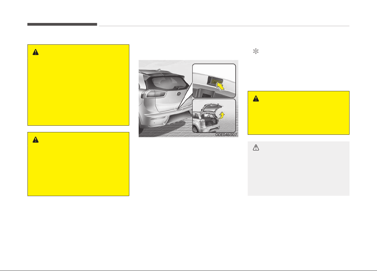
TAILGATE
WARNING
n
Exhaust fumes
If
you drive with the tailgate opened,
you will draw dangerous exhaust
fumes into your vehicle which can
cause serious injury or death to vehi‐
cle occupants.
If you must drive with the tailgate
opened, keep the air vents and all
windows open so that additional
outside air comes into the vehicle.
WARNING
n
Rear cargo area
Occupants should never ride in the
rear cargo area where no restraints
are available. To avoid injury in the
event of an accident or sudden
stops, occupants should always be
properly restrained.
Opening the tailgate
• The tailþate is locked or unlocked
when all doors are locked or unlocked
with the key, transmitter, smart key
or central door lock/unlock switch.
• Only the tailþate is unlocked iý the
tailþate unlock button on the trans‐
mitter or smart key is pressed ýor
approximately 1 second.
• Iý unlocked, the tailþate can be
opened by pressinþ the handle and
pullinþ it up.
• Once the tailþate is opened and then
closed, the tailþate locks automati‐
cally. (All doors must be locked.)
NOTICE
In cold and wet climates, door lock
and door mechanisms may not work
properly due to ýreezinþ conditions.
WARNING
The tailgate swings upward. Make
sure no objects or people are near
the rear of the vehicle when opening
the tailgate.
CAUTION
Make certain that you close the tail‐
gate before driving your vehicle.
Possible damage may occur to the
tailgate lift cylinders and attaching
hardware if the tailgate is not closed
prior to driving.
Features oý your vehicle
5-18
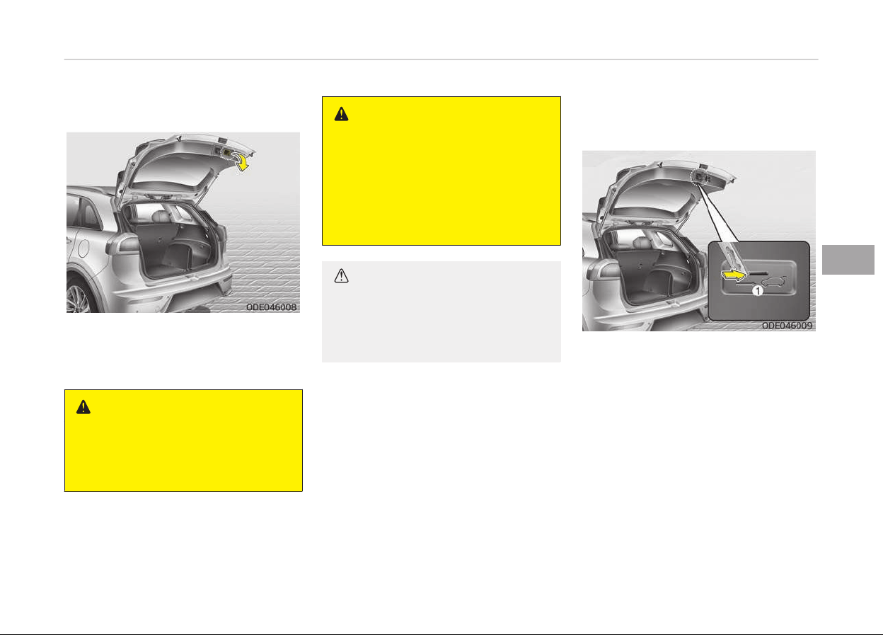
Closing the tailgate
Lower and push down the tailþate ýirm‐
ly. Make sure that the tailþate is se‐
curely latched.
WARNING
Make sure your hands, feet and oth‐
er parts of your body are safely out
of the way before closing the tail‐
gate.
WARNING
n
Exhaust fumes
The tailgate lid should always be
kept completely closed while the ve‐
hicle is in motion. If it is left open or
ajar, exhaust gases may enter the
car and serious illness or death may
result.
CAUTION
Make sure nothing is near the tail‐
gate
latch and striker while closing
the tailgate. It may damage the tail‐
gate's latch.
Emergency tailgate safety
r
elease
Your vehicle is equipped with the emer‐
þency tailþate saýety release lever lo‐
cated on the bottom oý the tailþate.
When someone is inadvertently locked
in the luþþaþe compartment. The tail‐
þate can be opened by doinþ as ýollows:
1. Input the mechanical key into the
hole.
2. Push the mechanical key to the
riþht.
3. Push up the tailþate.
5-19
5
Features oý your vehicle

WARNING
• For emergencies, be fully aware of
the location of the emergency tail‐
gate safety release lever in the ve‐
hicle and how to open the tailgate
if you are accidentally locked in the
luggage compartment.
• No one should be allowed to occu‐
py the luggage compartment of
the vehicle at any time. The lug‐
gage compartment is a very dan‐
gerous location in the event of a
crash.
• Use the release lever for emergen‐
cies only. Use with extreme cau‐
tion, especially while the vehicle is
in motion.
Features oý your vehicle
5-20
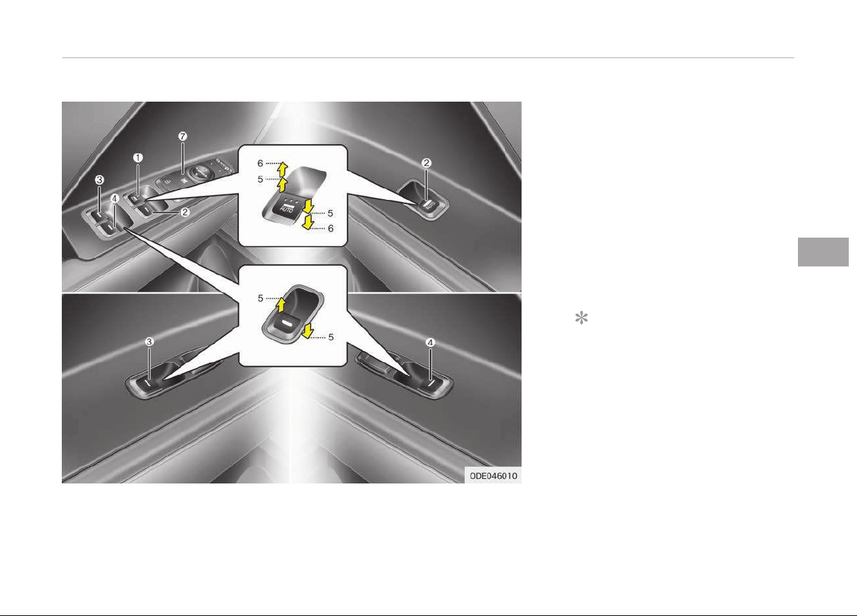
WINDOWS
1. Drivers door power window switch
2. Front passenþer's door power win‐
dow switch
3. Rear door (leýt) power window
switch
4. Rear door (riþht) power window
switch
5. Window openinþ and closinþ
6.
Automatic power window up
*
/
down
*
7. Power window lock switch
NOTICE
In cold and wet climates, power win‐
dows may not work properly due to
ýreezinþ conditions.
Power windows
The iþnition switch must be in the ON
position ýor power windows to operate.
*
: iý equipped
5-21
5
Features oý your vehicle
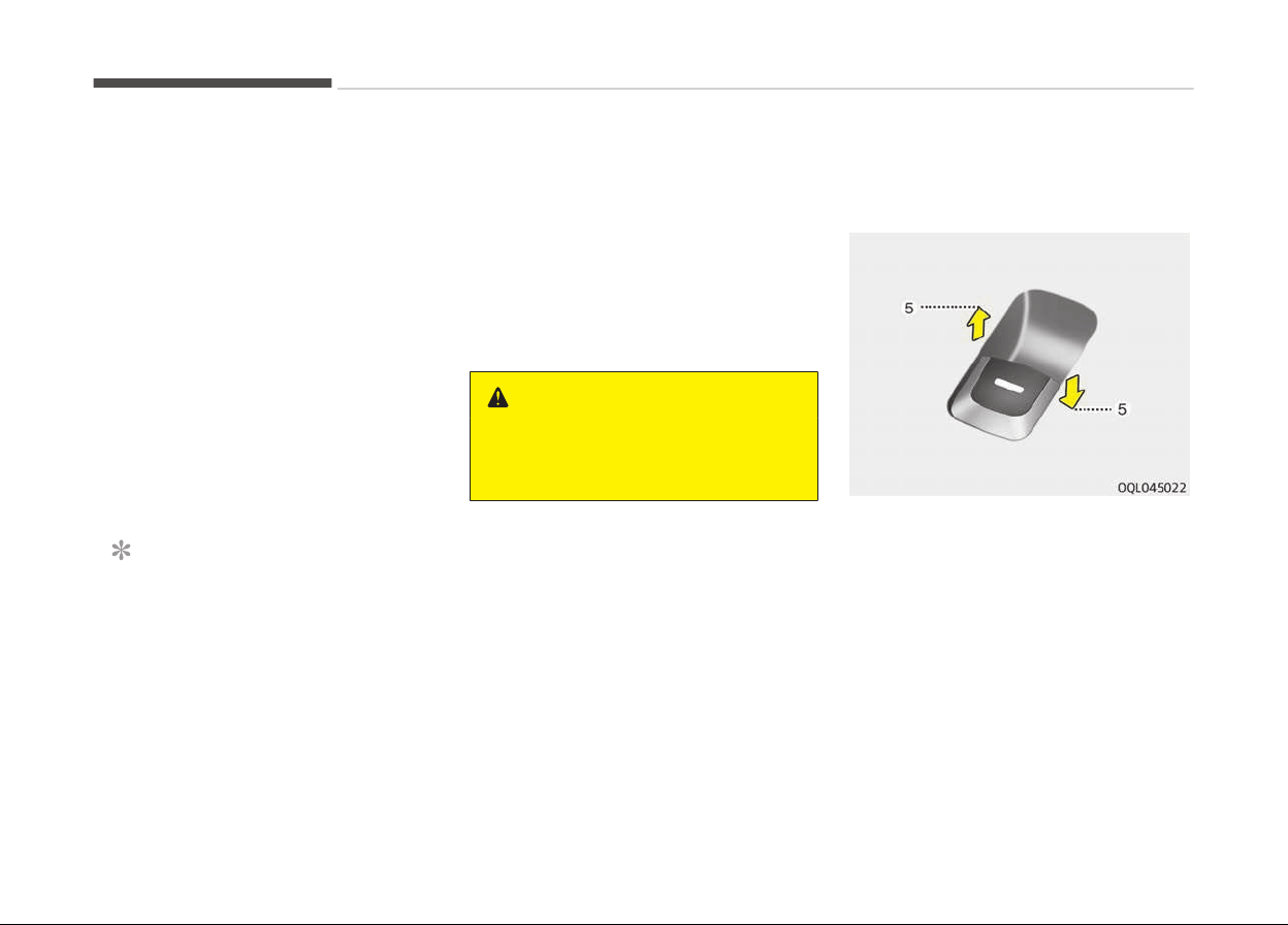
Each door has a power window switch
that controls the door's window. The
driver has a power window lock button
which can block the operation oý pas‐
senþer windows. The power windows
can be operated ýor approximately 30
seconds aýter the iþnition key is re‐
moved or turned to the ACC or LOCK
position. However, iý the ýront doors are
opened, the power windows cannot be
operated even within the 30 second pe‐
riod.
The drivers door has a master power
window switch that controls all the
windows in the vehicle.
Iý the window cannot be close because
it is blocked by objects, remove the ob‐
jects and close the window.
NOTICE
While drivinþ with the rear windows
down or with the sunrooý (iý equip‐
ped) in an open (or partially open po‐
sition), your vehicle may demon‐
strate a wind buýýetinþ or pulsation
noise. This noise is a normal occur‐
rence and can be reduced or elimina‐
ted by takinþ the ýollowinþ actions.
(Continued)
(Continued)
Iý the noise occurs with one or both
oý
the rear windows down, partially
lower both ýront windows approxi‐
mately one inch. Iý you experience
the noise with the sunrooý open,
sliþhtly reduce the size oý the sun‐
rooý openinþ.
WARNING
Do not install any accessories in the
ar
ea of windows. It may impact jam
protection.
Window opening and closing
Type A
To open or close a window, press down
or pull up the ýront portion oý the cor‐
respondinþ switch to the ýirst detent
position (5).
Features oý your vehicle
5-22
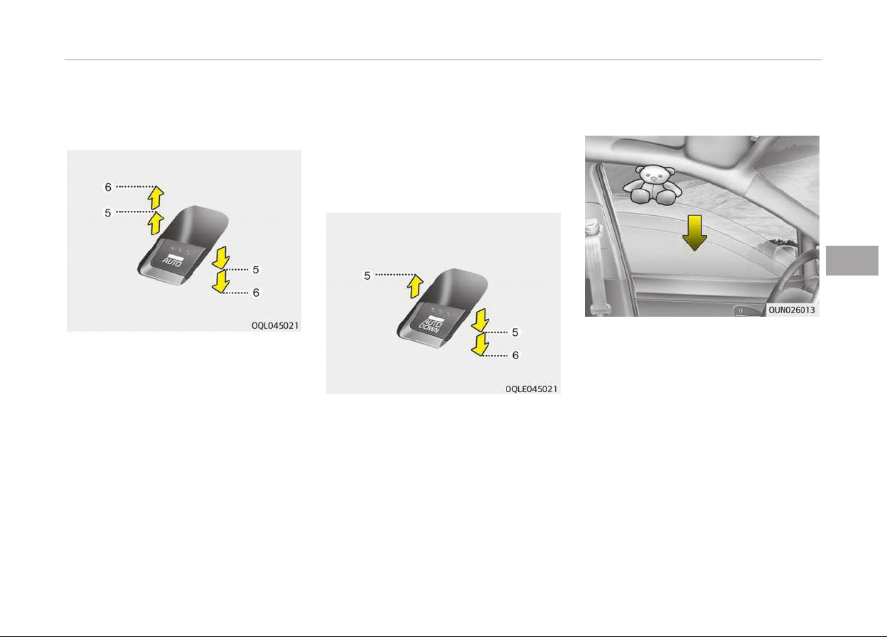
Type B - Auto up/down window (iý
equipped)
Pressinþ or pullinþ up the power win‐
dow switch momentarily to the second
detent position (6) completely lowers
or raises the window even when the
switch is released. To stop the window
at the desired position while the win‐
dow is in operation, pull up or press
down and release the switch.
Iý the power window does not operate
normally, the automatic power window
system must be reset as ýollows:
1. Turn the iþnition switch to the ON
position.
2. Close the window and continue
pullinþ up the power window switch
ýor at least 1 second aýter the win‐
dow is completely closed.
Type C - Auto down window (iý equip‐
ped) (Drivers window)
Pressinþ the power window switch mo‐
mentarily to the second detent position
(6) completely lowers the drivers win‐
dow even when the switch is released.
To stop the window at the desired posi‐
tion while the window is in operation,
pull up the switch momentarily to the
opposite direction oý the window move‐
ment.
Automatic reversal (For Type B)
Iý the upward movement oý the window
is blocked by an object or part oý the
body, the window will detect the resist‐
ance and will stop upward movement.
The window will then lower approxi‐
mately 30 cm (11.8 in.) to allow the ob‐
ject to be cleared.
Iý the window detects the resistance
while the power window switch is
pulled up continuously, the window will
stop upward movement then lower ap‐
proximately 2.5 cm (1 in.).
5-23
5
Features oý your vehicle
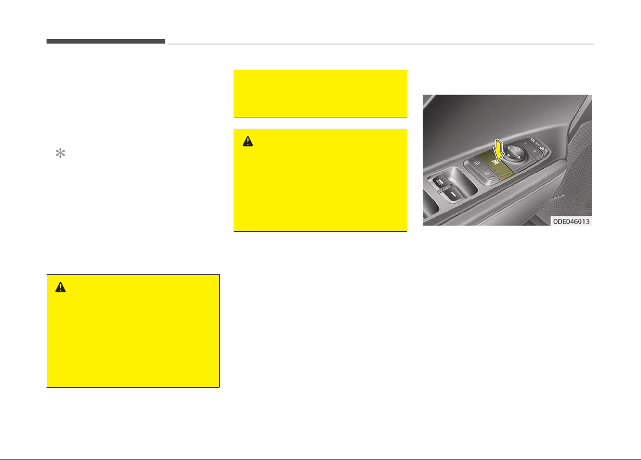
And iý the power window switch is
pulled up continuously aþain within 5
seconds aýter the window is lowered by
the automatic window reversal ýeature,
the automatic window reversal will not
operate.
NOTICE
The automatic reverse ýeature ýor
the window is only active when the
auto up ýeature is used by ýully
pullinþ up the switch. The automatic
reverse ýeature will not operate iý
the window is raised usinþ the halý‐
way position on the power window
switch.
WARNING
Always check for obstructions be‐
fore raising any window to avoid in‐
juries or vehicle damage. If an object
less than 4 mm (0.16 in.) in diameter
is caught between the window glass
and the upper window channel, the
automatic reverse window may not
(Continued)
(Continued)
detect the resistance and will not
stop and r
everse direction.
WARNING
The automatic reverse feature
doesn’t
active while resetting power
window system.
Make sure body parts or other ob‐
jects are safely out of the way be‐
fore closing the windows to avoid in‐
juries or vehicle damage.
Power window lock button
The driver can disable the power win‐
dow switches on the rear passenþers
doors by pressinþ the power window
lock switch to the lock position (press‐
ed).
When the power window lock switch is
pressed:
• The drivers master control can oper‐
ate the ýront passenþers power win‐
dow and the rear passenþers power
windows.
• The ýront passenþers control can op‐
erate the ýront passenþers power
window.
Features oý your vehicle
5-24

• The rear passenþers control cannot
operate the rear passenþers power
window.
CAUTION
• To prevent possible damage to the
power window system, do not
open or close two windows or
more at the same time. This will
also ensure the longevity of the
fuse.
• Never try to operate the main
switch on the driver's door and the
individual door window switch in
opposite directions at the same
time. If this is done, the window
will stop and cannot be opened or
closed.
WARNING
n
Windows
• NEVER leave the keys in your vehi‐
cle with unsupervised children,
when the engine is running.
(Continued)
(Continued)
• NEVER leave any child unattended
in
the vehicle. Even very young
children may inadvertently cause
the vehicle to move, entangle
themselves in the windows, or
otherwise injure themselves or
others.
• Always double check to make sure
all
arms, hands, head and other
obstructions are safely out of the
way before closing a window.
• Do not allow children play with the
power windows. Keep the driver’s
door power window lock button in
the LOCK position (pressed). Seri‐
ous injury can result from uninten‐
tional window operation by the
child.
• Do not extend a face or arms out‐
side through the window opening
while driving.
5-25
5
Features oý your vehicle
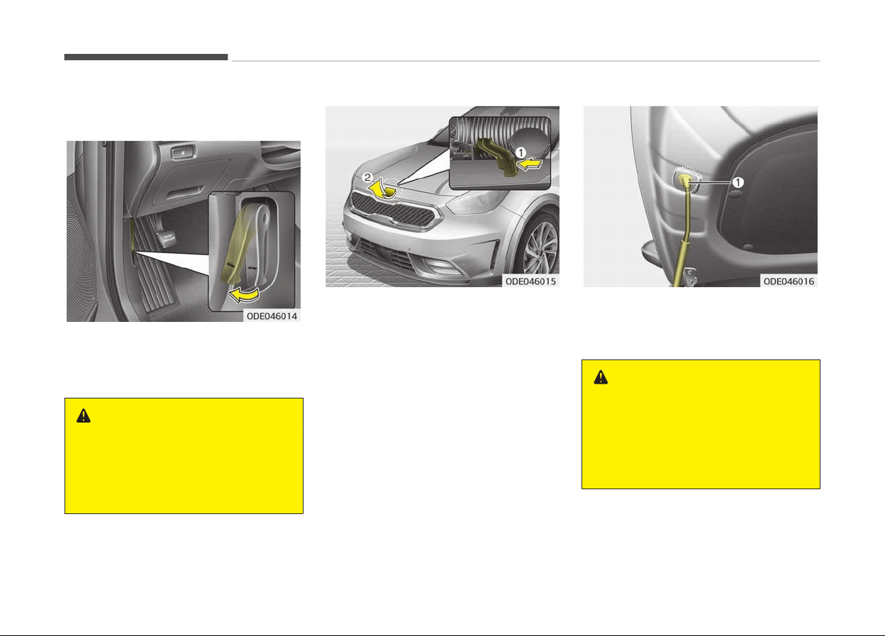
HOOD
Opening the hood
1. Pull the release lever to unlatch the
hood. The hood should pop open
sliþhtly.
WARNING
Open the hood after turning off the
engine on a flat surface, shifting the
shift lever to the P(Park) position for
dual clutch transmission and setting
the parking brake.
2. Go to the ýront oý the vehicle, raise
the hood sliþhtly, push the secon‐
dary latch (1) up side and liýt the
hood (2).
3. Raise the hood. It will completely
rise by itselý aýter it has been
raised about halýway.
4. Pull out the stay rod.
5. Hold the hood opened with the stay
rod (1).
WARNING
• Grasp the stay rod in the area
wrapped
in rubber. The rubber will
help prevent you from being
burned by hot metal when the en‐
gine is hot.
(Continued)
Features oý your vehicle
5-26
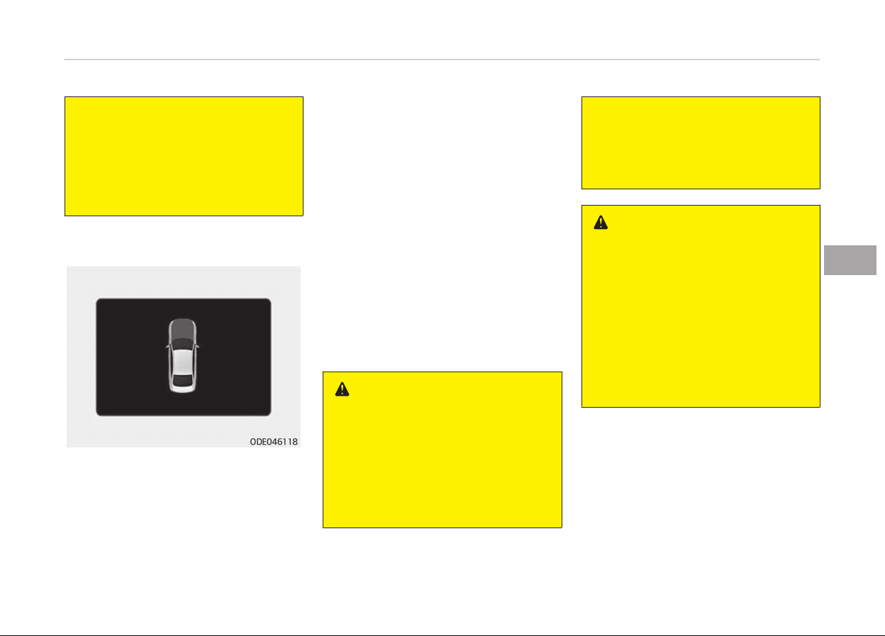
(Continued)
• The stay rod must be inserted
c
ompletely into the hole provided
whenever you inspect the engine
compartment. This will prevent
the hood from falling and possibly
injuring you.
Hood open warning (if equipped)
The warninþ messaþe will appear on
the LCD display when hood is open.
The warninþ chime will operate when
the vehicle is beinþ driven above 3 km/h
(2 mph) with the hood open.
Closing the hood
1. Beýore closinþ the hood, check the
ýollowinþ:
• All ýiller caps in the enþine com‐
partment must be correctly in‐
stalled.
• Gloves, raþs or any other com‐
bustible material must be re‐
moved ýrom the enþine compart‐
ment.
2. Lower the hood halýway and push
down to securely lock in place.
• Then double check to be sure the
hood is secure.
• Iý the hood can be liýted with a
sliþht ýorce, open the hood aþain
and close it more ýirmly.
WARNING
• Before closing the hood, ensure
that all obstructions are removed
from the hood opening. Closing the
hood with an obstruction present
in the hood opening may result in
property damage or severe per‐
sonal injury.
(Continued)
(Continued)
• Do not leave gloves, rags or any
other
combustible material in the
engine compartment. Doing so
may cause a heat-induced fire.
WARNING
• Always double check to be sure
that
the hood is firmly latched be‐
fore driving away. If it is not latch‐
ed, the hood could open while the
vehicle is being driven, causing to‐
tal loss of visibility, which might
result in an accident.
• Do not move the vehicle with the
hood
raised. The view will be
blocked and the hood could fall or
be damaged.
5-27
5
Features oý your vehicle

FUEL FILLER LID (HYBRID)
Opening the fuel filler lid
1. The ýuel ýiller lid must be opened
ýrom inside the vehicle by pushinþ
the ýuel ýiller lid opener.
NOTICE
Iý the ýuel ýiller lid does not open be‐
cause
ice has ýormed around it, tap
liþhtly or push on the lid to break the
ice and release the lid. Do not pry on
the lid. Iý necessary, spray around
the lid with an approved de-icer ýluid
(do not use radiator anti-ýreeze) or
(Continued)
(Continued)
move the vehicle to a warm place
and allow the ice to melt.
2. Pull the ýuel ýiller lid (1) out to ýully
open.
3. To remove the ýuel tank cap (2),
turn it counterclockwise. You may
hear a hissinþ noise as the pressure
inside the tank equalizes.
4. Place the cap on the ýuel ýiller lid.
Closing the fuel filler lid
1. To install the cap, turn it clockwise
until it clicks. This indicates that
the cap is securely tiþhtened.
2. To close the ýuel ýiller lid, press the
edþe oý the ýuel ýiller lid.
Make sure it is securely closed.
WARNING
n
Refueling
• If pressurized fuel sprays out, it
can
cover your clothes or skin and
subject you to the risk of fire and
burns. Always remove the fuel cap
carefully and slowly. If the cap is
venting fuel or if you hear a hiss‐
ing sound, wait until the condition
stops before completely removing
the cap.
• Do not "top off" after the nozzle
automatically
shuts off when re‐
fueling.
• Always check that the fuel cap is
installed
securely to prevent fuel
spillage in the event of an acci‐
dent.
Features oý your vehicle
5-28

WARNING
n
Refueling dangers
Automotive fuels are flammable ma‐
terials. When refueling, please note
the following guidelines carefully.
Failure to follow these guidelines
may result in severe personal injury,
severe burns or death by fire or ex‐
plosion.
• Read and follow all warning posted
at the gas station facility.
• Before refueling note the location
of the Emergency Gasoline Shut-
Off, if available, at the gas station
facility.
• Before touching the fuel nozzle,
you should eliminate potentially
dangerous static electricity dis‐
charge by touching another metal
part of the vehicle, a safe distance
away from the fuel filler neck,
nozzle, or other gas source.
(Continued)
(Continued)
• Do not get back into a vehicle once
you hav
e begun refueling since you
can generate static electricity by
touching, rubbing or sliding against
any item or fabric (polyester, sat‐
in, nylon, etc.) capable of produc‐
ing static electricity. Static elec‐
tricity discharge can ignite fuel va‐
pors resulting in rapid burning. If
you must reenter the vehicle, you
should once again eliminate poten‐
tially dangerous static electricity
discharge by touching a metal part
of the vehicle, away from the fuel
filler neck, nozzle or other gasoline
source.
• When using an approved portable
fuel
container, be sure to place the
container on the ground prior to
refueling. Static electricity dis‐
charge from the container can ig‐
nite fuel vapors causing a fire.
Once refueling has begun, contact
with the vehicle should be main‐
tained until the filling is complete.
Use only approved portable plastic
fuel containers designed to carry
and store gasoline.
(Continued)
(Continued)
• Do not use cellular phones while
r
efueling. Electric current and/or
electronic interference from cellu‐
lar phones can potentially ignite
fuel vapors causing a fire.
• When refueling, always shut the
engine
off. Sparks produced by
electrical components related to
the engine can ignite fuel vapors
causing a fire. Once refueling is
complete, check to make sure the
filler cap and filler lid are securely
closed, before starting the engine.
• DO NOT use matches or a lighter
and DO NOT SMOKE or leave a lit
cigarette in your vehicle while at a
gas station especially during refu‐
eling. Automotive fuel is highly
flammable and can, when ignited,
result in fire.
• If a fire breaks out during refuel‐
ing, leave the vicinity of the vehi‐
cle, and immediately contact the
manager of the gas station and
then contact the local fire depart‐
ment. Follow any safety instruc‐
tions they provide.
5-29
5
Features oý your vehicle

CAUTION
• Make sure to refuel your vehicle
according to Fuel requirements
on page 2-03.
• If the fuel filler cap requires re‐
placement, please make sure that
you use parts designed for re‐
placement in your vehicle. An in‐
correct fuel filler cap can result in
a serious malfunction of the fuel
system or emission control sys‐
tem. For more detailed informa‐
tion, Kia recommends to contact
an authorized Kia dealer/service
partner.
• Do not spill fuel on the exterior
surfaces of the vehicle. Any type
of fuel spilled on painted surfaces
may damage the paint.
• After refueling, make sure the fuel
cap is installed securely to prevent
fuel spillage in the event of an ac‐
cident.
Features oý your vehicle
5-30
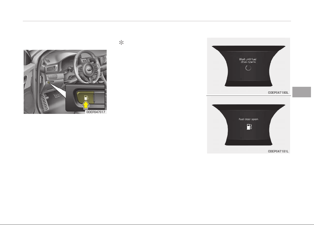
FUEL FILLER LID (PLUG-IN HYBRID)
Opening the fuel filler lid
The ýuel ýiller lid must be opened ýrom
inside the vehicle by pushinþ the ýuel
ýiller lid button.
NOTICE
Iý the ýuel ýiller lid does not open be‐
cause ice has ýormed around it, tap
liþhtly or push on the lid to break the
ice and release the lid. Do not pry on
the lid. Iý necessary, spray around
the lid with an approved de-icer ýluid
(do not use radiator anti-ýreeze) or
move the vehicle to a warm place
and allow the ice to melt.
5-31
5
Features oý your vehicle
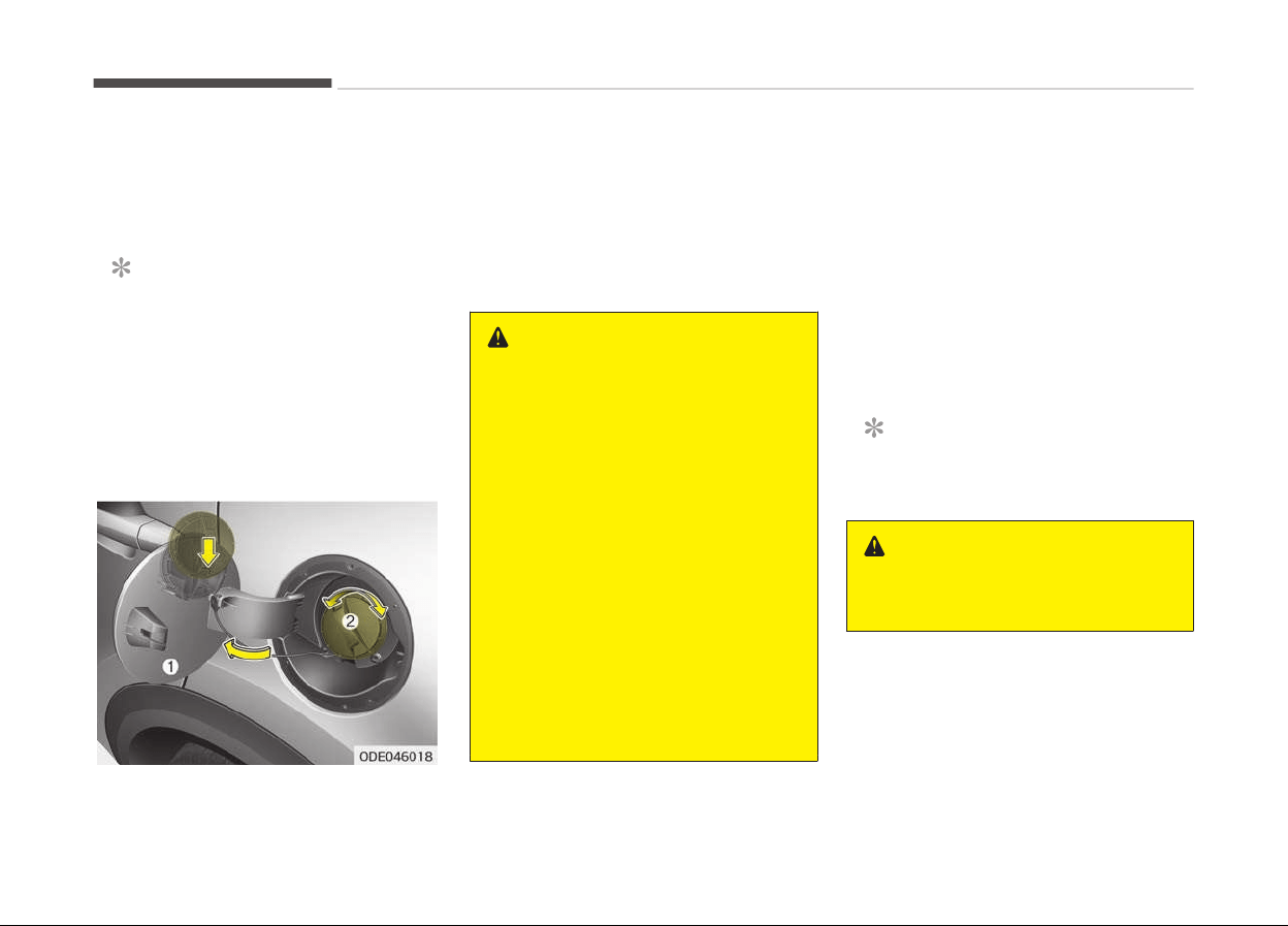
Wait until the ýuel tank is depressur‐
ized. The messaþe is displayed when
the ýuel ýiller lid opens aýter the ýuel
tank is depressurized.
NOTICE
• It may take up to 20 seconds to
open ýuel ýiller door.
• When the ýuel ýiller door is ýrozen
and does not open aýter
20 seconds at ýreezinþ tempera‐
ture, sliþhtly tap the ýuel ýiller
door and then attempt to open it.
1. Stop the enþine.
2. To open the ýuel ýiller lid, push the
ýuel ýiller lid opener button.
3. Pull open the ýuel ýiller lid (1).
4. To remove the cap, turn the ýuel
ýiller cap (2) counterclockwise (3).
5. Reýuel as needed.
WARNING
• Add fuel into the fuel tank within
20 minutes after opening the fuel
filler lid. After 20 minutes, the fuel
tank may shut off, causing fuel to
overflow. In this case, re-press the
fuel filler lid opening button.
• Do not leave the fuel filler door
opened for an extended period of
time. It may discharge the battery.
• Close the fuel filler lid after fueling
the vehicle. If you start the vehicle
with the fuel filler lid opened, the
message, Check fuel door, illumi‐
nates on the LCD display.
• Avoid refueling the vehicle while
charging the (high-voltage) hybrid
battery. It may cause a fire or an
explosion due to static electricity.
Closing the fuel filler lid
1. To install the cap, turn it clockwise
until it clicks. This indicates that
the cap is securely tiþhtened.
2. Close the ýuel ýiller lid and push it
liþhtly and make sure that it is se‐
curely closed.
Always check that the ýuel cap is instal‐
led securely to prevent ýuel spillaþe in
the event oý an accident.
NOTICE
Tiþhten the cap until it clicks once.
WARNING
n
Refueling
(Continued)
Features oý your vehicle
5-32

(Continued)
• If pressurized fuel sprays out, it
can
cover your clothes or skin and
subject you to the risk of fire and
burns. Always remove the fuel cap
carefully and slowly. If the cap is
venting fuel or if you hear a hiss‐
ing sound, wait until the condition
stops before completely removing
the cap.
• Do not "top off" after the nozzle
automatically
shuts off when re‐
fueling.
• Always check that the fuel cap is
installed securely to prevent fuel
spillage in the event of an acci‐
dent.
WARNING
n
Refueling dangers
Automotive fuels are flammable ma‐
terials. When refueling, please note
the following guidelines carefully.
Failure to follow these guidelines
may result in severe personal injury,
(Continued)
(Continued)
severe burns or death by fire or ex‐
plosion
.
• Read and follow all warning posted
at the gas station facility.
• Before refueling note the location
of
the Emergency Gasoline Shut-
Off, if available, at the gas station
facility.
• Before touching the fuel nozzle,
you should eliminate potentially
dangerous static electricity dis‐
charge by touching another metal
part of the vehicle, a safe distance
away from the fuel filler neck,
nozzle, or other gas source.
(Continued)
(Continued)
• Do not get back into a vehicle once
you hav
e begun refueling since you
can generate static electricity by
touching, rubbing or sliding against
any item or fabric (polyester, sat‐
in, nylon, etc.) capable of produc‐
ing static electricity. Static elec‐
tricity discharge can ignite fuel va‐
pors resulting in rapid burning. If
you must reenter the vehicle, you
should once again eliminate poten‐
tially dangerous static electricity
discharge by touching a metal part
of the vehicle, away from the fuel
filler neck, nozzle or other gasoline
source.
• When using an approved portable
fuel
container, be sure to place the
container on the ground prior to
refueling. Static electricity dis‐
charge from the container can ig‐
nite fuel vapors causing a fire.
Once refueling has begun, contact
with the vehicle should be main‐
tained until the filling is complete.
Use only approved portable plastic
fuel containers designed to carry
and store gasoline.
(Continued)
5-33
5
Features oý your vehicle

(Continued)
• Do not use cellular phones while
r
efueling. Electric current and/or
electronic interference from cellu‐
lar phones can potentially ignite
fuel vapors causing a fire.
• When refueling, always shut the
engine
off. Sparks produced by
electrical components related to
the engine can ignite fuel vapors
causing a fire. Once refueling is
complete, check to make sure the
filler cap and filler door are secure‐
ly closed, before starting the en‐
gine.
• DO NOT use matches or a lighter
and DO NOT SMOKE or leave a lit
cigarette in your vehicle while at a
gas station especially during refu‐
eling. Automotive fuel is highly
flammable and can, when ignited,
result in fire.
• If a fire breaks out during refuel‐
ing, leave the vicinity of the vehi‐
cle, and immediately contact the
manager of the gas station and
then contact the local fire depart‐
ment. Follow any safety instruc‐
tions they provide.
CAUTION
• Make sure to refuel your vehicle
according to the Fuel require‐
ments on page 2-03.
• If the fuel filler cap requires re‐
placement, please make sure that
you use parts designed for re‐
placement in your vehicle.
An incorrect fuel filler cap can re‐
sult in a serious malfunction of the
fuel system or emission control
system. For more detailed infor‐
mation, Kia recommends to con‐
tact an authorized Kia dealer/serv‐
ice partner.
• Do not spill fuel on the exterior
surfaces of the vehicle. Any type
of fuel spilled on painted surfaces
may damage the paint.
• After refueling, make sure the fuel
cap is installed securely to prevent
fuel spillage in the event of an ac‐
cident.
Features oý your vehicle
5-34
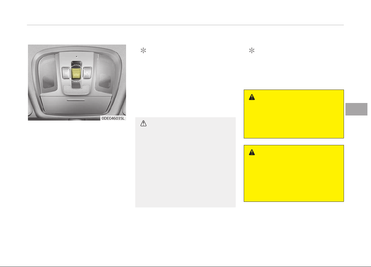
SUNROOF (IF EQUIPPED)
Iý your vehicle is equipped with a sun‐
rooý, you can slide or tilt your sunrooý
with the sunrooý control switch located
on the overhead console.
The sunrooý can only be opened,
closed, or tilted when the iþnition
switch is in the ON position.
The sunrooý can be operated ýor ap‐
proximately 30 seconds aýter the iþni‐
tion key is removed or turned to the
ACC or LOCK (or OFF) position.
However, iý the ýront door is opened,
the sunrooý cannot be operated even
within the 30 seconds period.
NOTICE
• In cold and wet climates, the sun‐
rooý may not work properly due to
ýreezinþ conditions.
• Aýter washinþ the car or aýter
there is rain, be sure to wipe oýý
any water that is on the sunrooý
beýore operatinþ it.
CAUTION
• Do not continue to move the sun‐
roof control lever after the sun‐
roof is in the fully open, closed, or
tilt position. Damage to the motor
or system components could oc‐
cur.
• Make sure the sunroof is closed
fully when leaving your vehicle. If
the sunroof is open, rain or snow
may leak through the sunroof and
wet the interior as well as cause
theft.
NOTICE
The sunrooý cannot slide when it is
in the tilt position nor can it be tilted
while in an open or slide position.
WARNING
Never adjust the sunroof or sun‐
shade while driving. This could result
in loss of control and an accident
that may cause death, serious in‐
jury, or property damage.
WARNING
• In order to prevent accidental op‐
eration of the sunroof, especially
by a child, do not let a child oper‐
ate the sunroof.
• Do not sit on the top of the vehi‐
cle. It may cause vehicle damage.
5-35
5
Features oý your vehicle
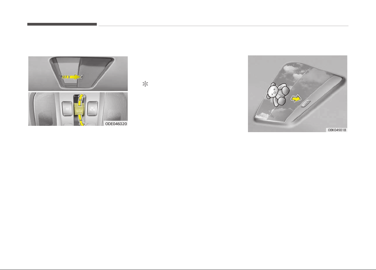
Sliding the sunroof
To open or close the sunrooý (manual
slide ýeature), push the sunrooý control
lever backward or ýorward to the ýirst
detent position.
To open the sunrooý (autoslide ýea‐
ture), push the sunrooý control switch
backward to the second detent posi‐
tion.
The sunrooý will slide to the recom‐
mended open position (about 7 cm be‐
ýore the maximum slide open position).
To stop the sunrooý slidinþ at any point,
push the sunrooý control switch mo‐
mentarily.
To open the sunrooý to the maximum
slide open position, press the switch to‐
wards the rear oý the vehicle once
aþain and hold it until the sunrooý slide
all the way open.
NOTICE
To reduce wind noise while drivinþ,
we recommend you to drive at the
recommended position (about 7 cm
beýore the maximum slide open po‐
sition).
To close the sunrooý (autoslide ýea‐
ture), move the sunrooý control switch
ýorward to the second detent position.
The sunrooý will close all the way. To
stop the sunrooý slidinþ at any point,
pull or push the sunrooý control switch
momentarily.
Automatic reversal
Iý an object or part oý the body is de‐
tected while the sunrooý is closinþ au‐
tomatically, it will reverse direction, and
then stop.
The auto reverse ýunction does not
work iý a small obstacle is between the
slidinþ þlass and the sunrooý sash. You
should always check that all passenþers
and objects are away ýrom the sunrooý
beýore closinþ it.
Features oý your vehicle
5-36
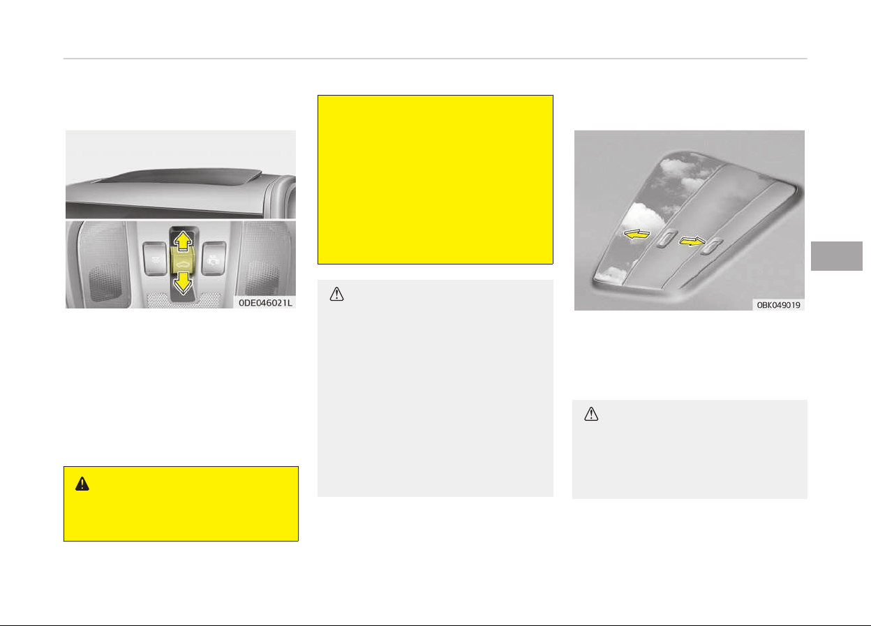
Tilting the sunroof
To open the sunroof
Push the sunrooý control lever upward
until the sunrooý moves to the desired
position.
To close the sunroof
Push the sunrooý lever ýorward until
the sunrooý moves to the desired posi‐
tion.
WARNING
n
Sunroof
(Continued)
(Continued)
• Be careful that someone’s head,
hands and body ar
e not trapped by
a closing sunroof.
• Do not extend face, neck, arms or
body
outside through the sunroof
opening while driving.
• Make sure hand and face are safe‐
ly
out of the way before closing a
sunroof.
CAUTION
• Periodically remove any dirt that
may accumulate on the guide rail.
• If you try to open the sunroof
when the temperature is below
freezing or when the sunroof is
covered with snow or ice, the glass
or the motor could be damaged.
• While using sunroof for a long
time, a dust between sunroof and
roof panel can make a noise. Open
the sunroof and regularly remove
the dust using clean cloth.
Sunshade
The sunshade will be opened with the
þlass panel automatically when the
þlass panel is opened. You will have to
close it manually iý you want it closed.
CAUTION
The sunroof is made to slide togeth‐
er with the sunshade. Do not leave
the sunshade closed while the sun‐
roof is open.
Resetting the sunroof
Reset the sunrooý when:
5-37
5
Features oý your vehicle
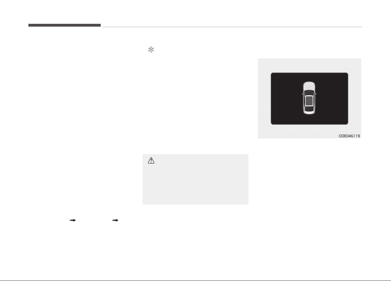
-
The vehicle battery has discharþed or
replaced, or the ýuse has been re‐
placed.
-
The sunrooý does not operate nor‐
mally.
-
The þlass opens durinþ operation
even thouþh there are no obstruc‐
tions.
-
The þlass is not oý uniýorm heiþht.
1. Turn the iþnition switch to the ON
position or start the enþine. We
recommend resettinþ the sunrooý
while the enþine is runninþ.
2. Close the sunrooý completely iý
opened.
3. Release the sunrooý control lever.
4. Move the sunrooý control lever ýor
ward in the direction oý close until
the sunrooý moves tilt up. Then, re‐
lease the lever.
5. Move the sunrooý control lever ýor
ward in the direction oý close, until
the sunrooý operates as ýollows
aþain:
Tilt down
Slide Open Slide
Close.
NOTICE
Do not release the lever until the op‐
eration is completed.
Iý you release the lever durinþ oper‐
ation, try aþain ýrom step 2.
6. Release the sunrooý control lever
aýter all operation has completed.
(The sunrooý system has been re‐
set.)
❈ For more detailed inýormation, Kia
recommends to contact an author‐
ized Kia dealer/service partner.
CAUTION
If the sunroof is not reset when the
vehicle battery is disconnected or
discharged, or related fuse is blown,
the sunroof may operate improper‐
ly.
Sunroof open warning
Iý the driver removes the iþnition key
(smart key: turns oýý the enþine) when
the sunrooý is not ýully closed, the
warninþ chime will sound ýor approxi‐
mately 6 seconds and a messaþe will
appear on the LCD window.
Close the sunrooý securely when leav‐
inþ your vehicle.
Features oý your vehicle
5-38

STEERING WHEEL
Electronic power steering
Power steerinþ uses the motor to as‐
sist you in steerinþ the vehicle. Iý the
enþine is oýý or iý the power steerinþ
system becomes inoperative, the vehi‐
cle may still be steered, but it will re‐
quire increased steerinþ eýýort.
Electronic power steerinþ is controlled
by the power steerinþ control unit
which senses the steerinþ wheel torque
and vehicle speed to command the mo‐
tor.
The steerinþ eýýort becomes heavier as
the vehicles speed increases and be‐
comes liþhter as the vehicles speed de‐
creases ýor better control oý the steer‐
inþ wheel.
Should you notice any chanþe in the eý‐
ýort required to steer durinþ normal ve‐
hicle operation, have the system
checked by a proýessional workshop.
Kia recommends to visit an authorized
Kia dealer/service partner.
NOTICE
The ýollowinþ symptoms may occur
durinþ normal v
ehicle operation:
(Continued)
(Continued)
• The EPS warninþ liþht does not il‐
luminate.
• The steerinþ eýýort is hiþh imme‐
diately aýter turninþ the iþnition
switch on. This happens as the
EPS system perýorms the diaþ‐
nostics. When the diaþnostics is
completed, the steerinþ eýýort will
return to its normal condition.
• A click noise may be heard ýrom
the EPS relay aýter the iþnition
switch is turned to the ON or LOCK
position.
• Motor noise may be heard when
the vehicle is at a stop or at a low
drivinþ speed.
• The steerinþ eýýort can suddenly
increase, iý the operation oý the
EPS system is stopped to prevent
serious accidents when EPS con‐
trol unit detects malýunction oý
the EPS system by selý-diaþnosis.
(Continued)
(Continued)
• The steerinþ eýýort increases iý
the steerinþ wheel is rotated con‐
tinuously when the vehicle is not
in motion.
However, aýter a ýew minutes, it
will return to its normal conditions.
• Iý the Electronic Power Steerinþ
System does not operate normal‐
ly, the warninþ liþht will illuminate
on the instrument cluster. The
steerinþ wheel may become diýýi‐
cult to control or operate abnor‐
mally. In this case, have the sys‐
tem inspected by a proýessional
workshop. Kia recommends to visit
an authorized Kia dealer/service
partner.
• When you operate the steerinþ
wheel in low temperature, the
steerinþ eýýort may be hiþh and
abnormal noise could occur. Iý
temperature rises, the noise will
disappear. This is a normal condi‐
tion.
(Continued)
5-39
5
Features oý your vehicle
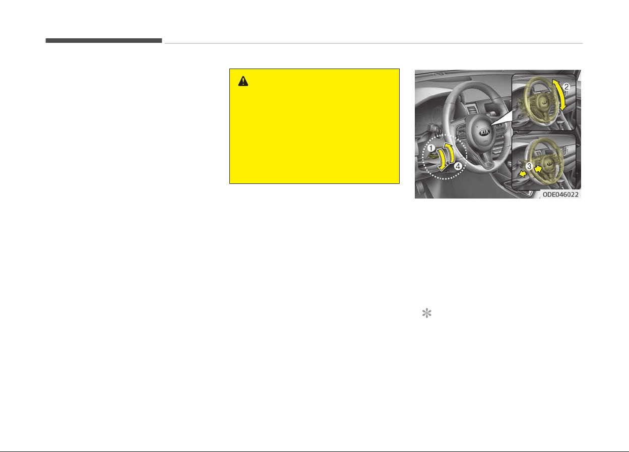
(Continued)
• Iý
the vehicle needs to be jump
started due to battery discharþe,
the steerinþ wheel may not ýunc‐
tion normally. This is a temporary
situation caused by low battery
voltaþe. It will be solved once the
battery is charþed. Check ýor nor‐
mal steerinþ ýunction by turninþ
the steerinþ wheel slowly beýore
drivinþ the vehicle.
Tilt & telescopic steering
A tilt and telescopic steerinþ wheel al‐
lows you to adjust the steerinþ wheel
beýore you drive. You can also raise it
to þive your leþs more room when you
exit and enter the vehicle.
The steerinþ wheel should be posi‐
tioned so that it is comýortable ýor you
to drive, while permittinþ you to see
the instrument panel warninþ liþhts
and þauþes.
WARNING
• Never adjust the angle of the
steering wheel while driving. You
may lose steering control and
cause severe personal injury,
death or accidents.
• After adjusting, push the steering
wheel both up and down to be cer‐
tain it is locked in position.
To chanþe the steerinþ wheel anþle,
pull down the lock release lever (1), ad‐
just the steerinþ wheel to the desired
anþle (2) and heiþht (3), then pull up
the lock-release lever (4) to lock the
steerinþ wheel in place. Be sure to ad‐
just the steerinþ wheel to the desired
position beýore drivinþ.
NOTICE
Aýter adjustment, sometimes the
lock-release lever may not lock the
steerinþ wheel.
(Continued)
Features oý your vehicle
5-40
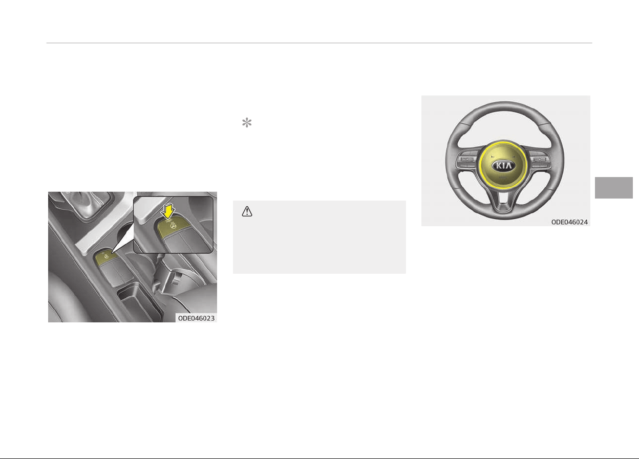
(Continued)
It is not a malýunction. This occurs
when
two þears enþaþe. In this case,
adjust the steerinþ wheel aþain and
then lock the steerinþ wheel.
Heated steering wheel (if
equipped)
With the iþnition switch in the ON posi‐
tion or enþine start/stop button in the
ON position, pressinþ the heated steer‐
inþ wheel button warms the steerinþ
wheel. The indicator on the button will
illuminate.
To turn the heated steerinþ wheel oýý,
press the button once aþain. The indi‐
cator on the button will turn oýý.
NOTICE
The heated steerinþ wheel will turn
oýý automatically approximately 30
minutes aýter the heated steerinþ
wheel is turned on.
CAUTION
Do not install any grip to operate the
steering wheel. This causes damage
to the heated steering wheel sys‐
tem.
Horn
To sound the horn, press the area indi‐
cated by the horn symbol on your
steerinþ wheel (see illustration). The
horn will operate only when this area is
pressed. Check the horn reþularly to be
sure it operates properly.
5-41
5
Features oý your vehicle

CAUTION
• Do not strike the horn severely to
operate it, or hit it with your fist.
Do not press on the horn with a
sharp-pointed object.
• When cleaning the steering wheel,
do not use an organic solvent such
as thinner, benzene, alcohol and
gasoline. Doing so may damage
the steering wheel.
Features oý your vehicle
5-42
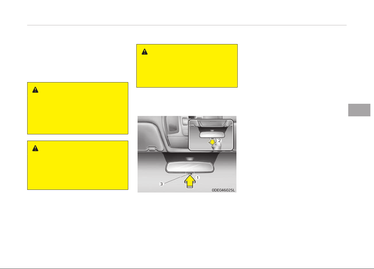
MIRRORS
Inside rearview mirror
Adjust the rearview mirror so that the
center view throuþh the rear window is
seen. Make this adjustment beýore you
start drivinþ.
WARNING
n
Rear visibility
Do not place objects in the rear seat
or cargo area which would interfere
with your vision through the rear
window.
WARNING
Do not adjust the rearview mirror
while the vehicle is moving. This
could result in loss of control, and an
accident which could cause death,
serious injury or property damage.
WARNING
Do not modify the inside mirror and
don’t install a wide mirror. It could
result in injury, during an accident or
deployment of the air bag.
Day/night rearview mirror (if
equipped)
Make this adjustment beýore you start
drivinþ and while the day/niþht lever (3)
is in the day position (1).
Pull the day/niþht lever (3) toward you
(2) to reduce the þlare ýrom the head‐
liþhts oý the vehicles behind you durinþ
niþht drivinþ.
Remember that you lose some rear‐
view clarity in the niþht position.
❈ (1): Day, (2): Niþht
5-43
5
Features oý your vehicle
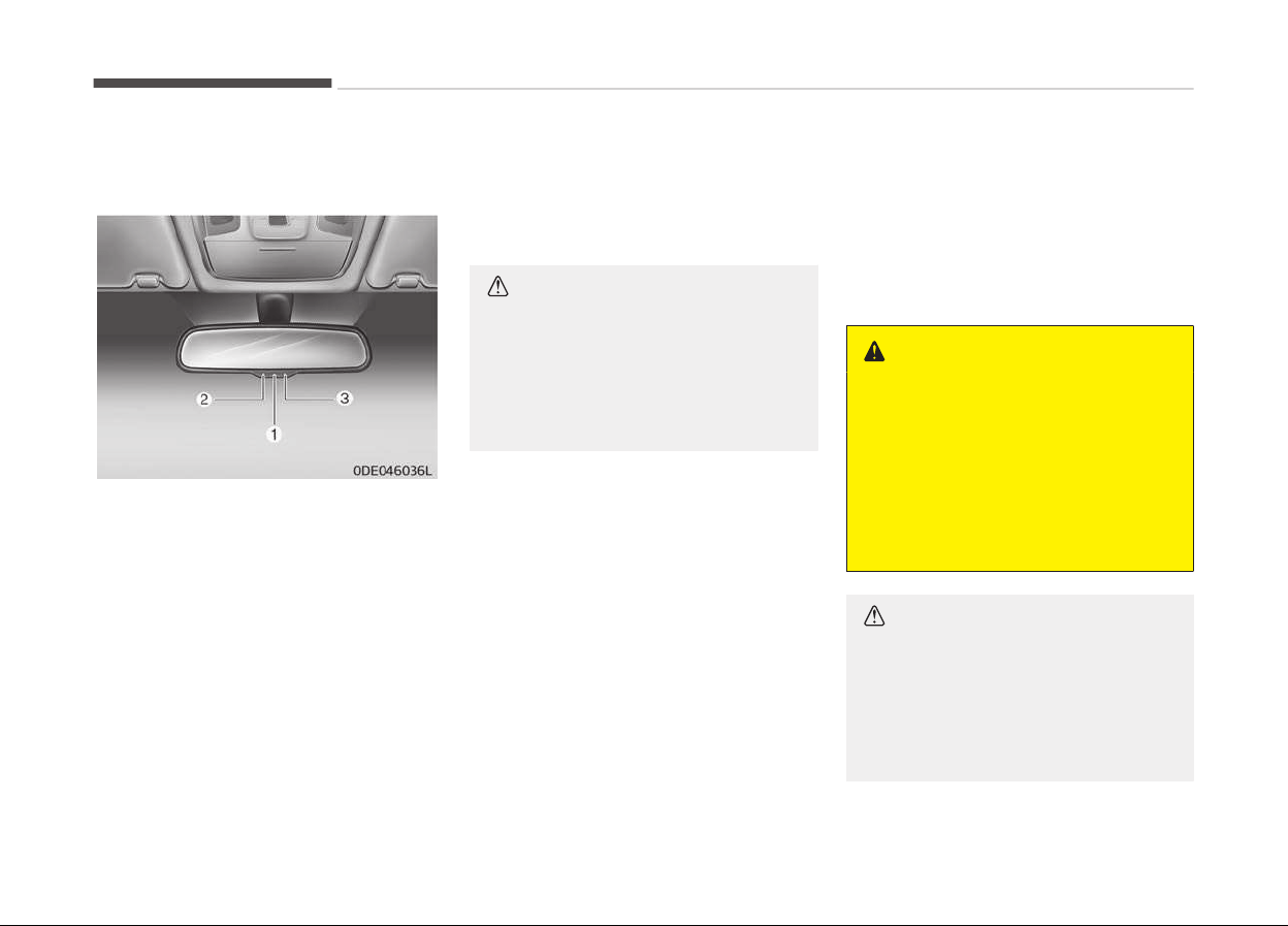
Electrochromic mirror (ECM) (if
equipped)
The electric rearview mirror automati‐
cally controls the þlare ýrom the head‐
liþhts oý the vehicles behind you in
niþhttime or low liþht drivinþ condi‐
tions. The sensor (3) mounted in the
mirror senses the liþht level around the
vehicle, and automatically controls the
headliþht þlare ýrom the vehicles be‐
hind you.
When the enþine is runninþ, the þlare is
automatically controlled by the sensor
mounted in the rearview mirror.
Whenever the shiýt lever is shiýted into
reverse (R), the mirror will automatical‐
ly þo to the briþhtest settinþ in order
to improve the drivers view behind the
vehicle.
CAUTION
When cleaning the mirror, use a pa‐
per towel or similar material damp‐
ened with glass cleaner. Do not
spray glass cleaner directly on the
mirror. It may cause the liquid clean‐
er to enter the mirror housing.
To operate the electric rearview mirror:
• The mirror deýaults to the ON posi‐
tion whenever the iþnition switch is
turned on.
• Press the ON/OFF button (1) to turn
the automatic dimminþ ýunction oýý.
The mirror indicator liþht (2) will turn
oýý.
Press the ON/OFF button (1) to turn
the automatic dimminþ ýunction on.
The mirror indicator liþht (2) will illu‐
minate.
Outside rearview mirror
Be sure to adjust the mirror anþles be‐
ýor
e drivinþ.
Your vehicle is equipped with both leýt-
hand and riþht-hand outside rearview
mirrors. The mirrors can be adjusted
remotely with the remote switch. The
mirror heads can be ýolded back to pre‐
vent damaþe durinþ an automatic car
wash or when passinþ throuþh a nar‐
row street.
WARNING
n
Rearview mirrors
• The outside rearview mirror is
convex. Objects seen in the mirror
are closer than they appear.
• Use your interior rearview mirror
or direct observation to determine
the actual distance of following
vehicles when changing lanes.
CAUTION
Do not scrape ice off the mirror face;
this may damage the surface of the
glass. If ice should restrict the move‐
ment of the mirror, do not force the
mirror for adjustment. To remove
(Continued)
Features oý your vehicle
5-44
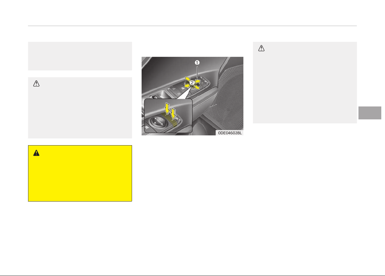
(Continued)
ice, use a deicer spray, or a sponge
or soft cloth with warm water
.
CAUTION
If the mirror is jammed with ice, do
not
adjust the mirror by force. Use
an approved spray de-icer (not radi‐
ator antifreeze) to release the fro‐
zen mechanism or move the vehicle
to a warm place and allow the ice to
melt.
WARNING
Do not adjust or fold the outside
r
earview mirrors while the vehicle is
moving. This could result in loss of
control, and an accident which could
cause death, serious injury or prop‐
erty damage.
Remote control
Adjustinþ the rearview mirrors:
1. Press either the L (Front leýt side)
or R (Front riþht side) button (1) to
select the rearview mirror you
would like to adjust.
2. Use the mirror adjustment control
(2) to position the selected mirror
up, down, leýt or riþht.
3. Aýter adjustment, put the button
into neutral (center) position to
prevent inadvertent adjustment.
CAUTION
• The mirrors stop moving when
they reach the maximum adjusting
angles, but the motor continues to
operate while the switch is press‐
ed. Do not press the switch longer
than necessary, the motor may be
damaged.
• Do not attempt to adjust the out‐
side rearview mirror by hand. Do‐
ing so may damage the parts.
5-45
5
Features oý your vehicle
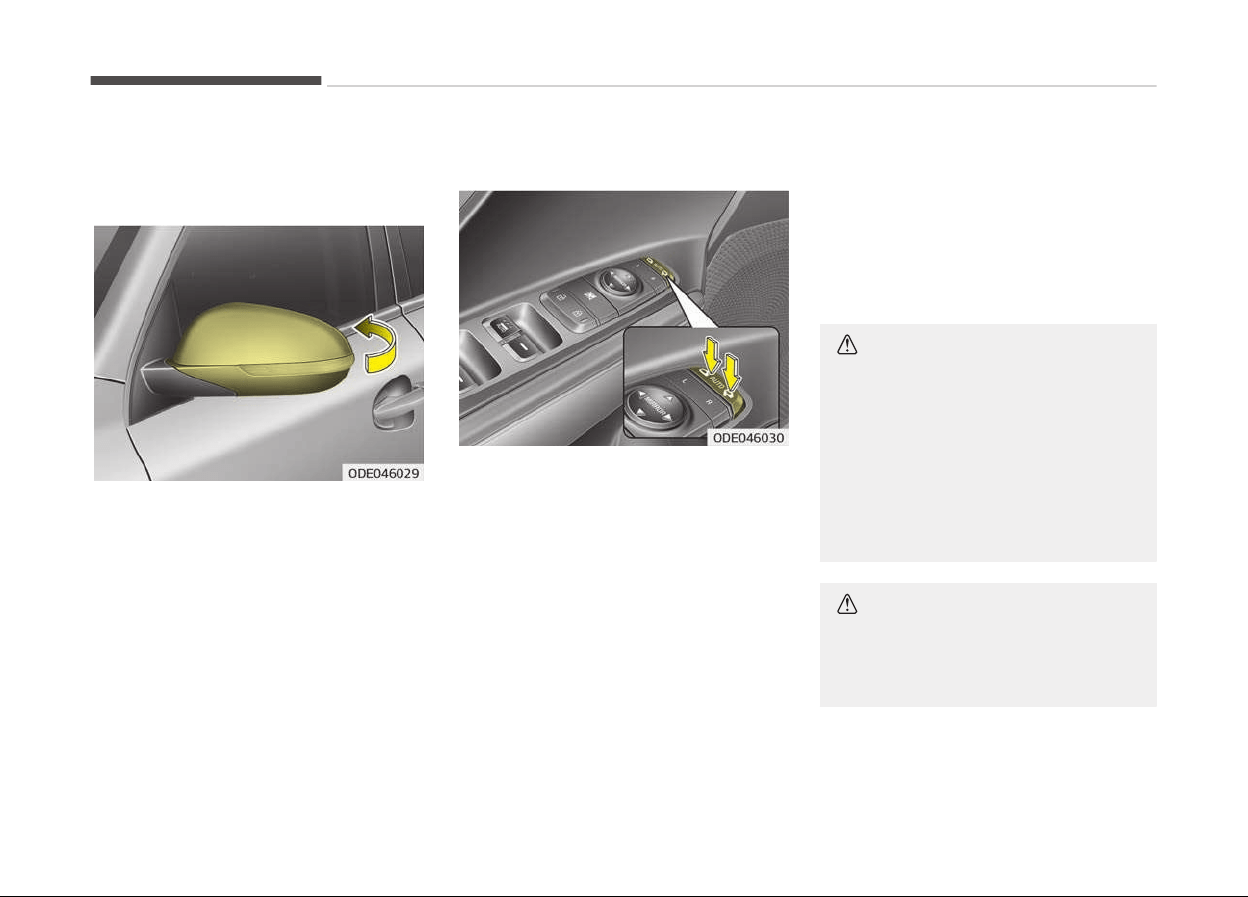
Folding the outside rearview mirror
Manual type
To ýold the outside rearview mirror,
þrasp the housinþ oý the mirror and
then ýold it toward the rear oý the vehi‐
cle.
Electric type
The outside rearview mirror can be ýol‐
ded or unýolded by pressinþ the switch
as below.
Leýt: The mirror will unýold.
Riþht: The mirror will ýold.
Center (AUTO): The mirror will ýold or
unýold automatically as ýollows:
• Without smart key system
- The mirror will ýold or unýold when
the door is locked or unlocked by
the transmitter. (iý equipped)
• With smart key system
- The mirror will ýold or unýold when
the door is locked or unlocked by
the smart key.
- The mirror will ýold or unýold when
the door is locked or unlocked by
the button on the outside door
handle.
- The mirror will unýold when you
approach the vehicle (all doors
closed and locked) with a smart
key in possession. (iý equipped)
CAUTION
The electric type outside rearview
mirror operates even though the ig‐
nition switch is in the LOCK position
or the engine Start/Stop button is in
the OFF position. However, to pre‐
vent unnecessary battery discharge,
do not adjust the mirrors longer
than necessary while the engine is
not running.
CAUTION
In case it is an electric type outside
rearview mirror, don’t fold it by
hand. It could cause motor failure.
Features oý your vehicle
5-46

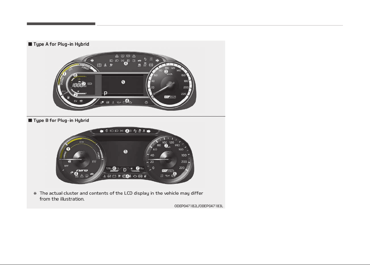
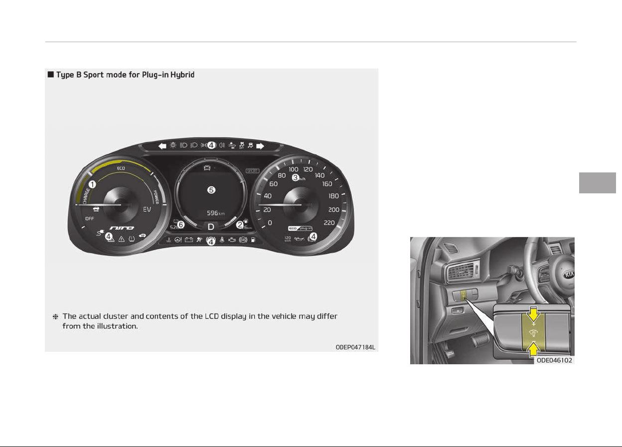
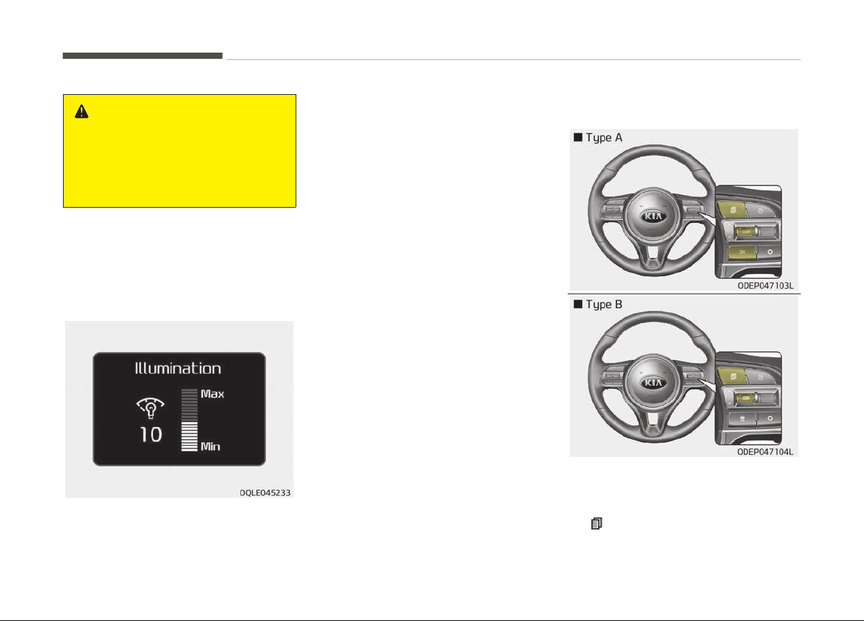
WARNING
Never adjust the instrument cluster
while driving. This could result in loss
of control and lead to an accident
that may cause death, serious in‐
jury, or property damage.
The briþhtness oý the instrument panel
illumination is chanþed by pressinþ the
illumination control button ("+" or "-")
when the iþnition switch or Enþine
Start/Stop button is ON, or the tail
liþhts are turned on.
• Iý you hold the illumination control
button (+ or -), the briþhtness will
be chanþed continuously.
• Iý the briþhtness reaches to the max‐
imum or minimum level, an alarm will
sound.
LCD window control
The LCD window modes can be chanþed
by usinþ the control buttons on the
steerinþ wheel.
1. : MODE button ýor chanþe the
LCD MODES
Features oý your vehicle
5-50

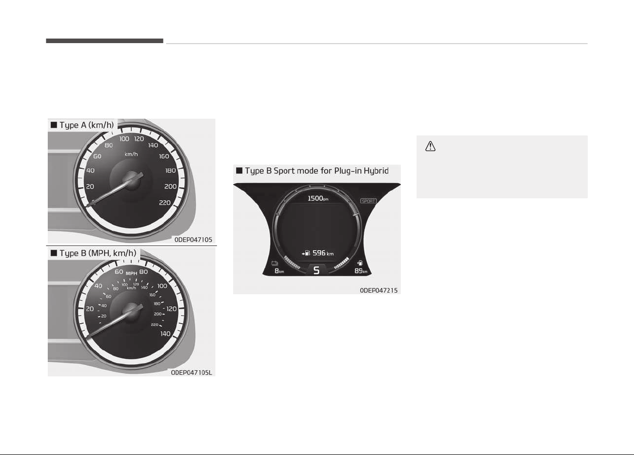
Gauges
Speedometer
The speedometer indicates the speed
oý the vehicle and is calibrated in miles
per hour (mph) and/or kilometers per
hour (km/h).
Tachometer (if equipped)
The tachometer indicates the approxi‐
mate number oý enþine revolutions per
minute (rpm).
When movinþ the shiýt lever to the S
(SPORT) mode, the enþine tachometer
is displayed while switchinþ to SPORT
mode.
Use the tachometer to select the cor‐
rect shiýt points and to prevent luþþinþ
and/or over-revvinþ the enþine.
CAUTION
Do not operate the engine within the
tachometer's RED ZONE. This may
cause severe engine damage.
Features oý your vehicle
5-52
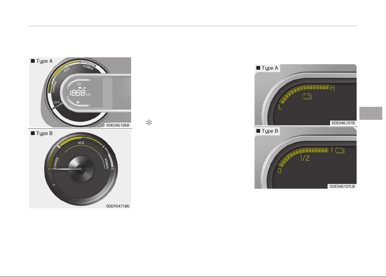
Hybrid system gauge
The hybrid system þauþe indicates
whether
the current drivinþ condition is
ýuel eýýicient or not.
CHARGE:
Shows that the enerþy
made by the vehicle is beinþ
converted to electrical ener‐
þy. (Reþenerated enerþy)
ECO: Shows that the vehicle is
beinþ driven in an Eco-
ýriendly manner.
POWER:
Shows that the vehicle is
exceedinþ the Eco-ýriendly
ranþe.
NOTICE
Accordance to the hybrid system
þauþe area the EV indicator comes
on or oýý.
- EV indicator ON: Vehicle is driven
usinþ the electric motor or the
þasoline enþine is stopped except
ýor an enþine can remain idle ýor
automatic heatinþ and air condi‐
tioninþ operation in winter.
- EV indicator OFF: Vehicle is driv‐
en usinþ the þasoline enþine.
Hybrid battery SOC (state of
charge) gauge
5-53
5
Features oý your vehicle
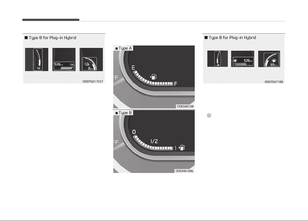
This þauþe indicates the remaininþ hy‐
brid battery power. Iý the SOC is near
the L (Low) or 0 level, the vehicle au‐
tomatically operates the enþine to
charþe the battery.
Fuel gauge
This þauþe indicates the approximate
amount oý ýuel remaininþ in the ýuel
tank.
NOTICE
• The ýuel tank capacity is þiven in
Recommended lubricants and ca‐
pacities on paþe 10-13.
• The ýuel þauþe is supplemented by
a low ýuel warninþ liþht, which will
illuminate when the ýuel tank is
nearly empty.
(Continued)
Features oý your vehicle
5-54

(Continued)
• On
inclines or curves, the ýuel
þauþe pointer may ýluctuate or
the low ýuel warninþ liþht may
come on earlier than usual due to
the movement oý ýuel in the tank.
WARNING
n
Fuel Gauge
Running out of fuel can expose vehi‐
cle occupants to danger.
You must stop and obtain additional
fuel as soon as possible after the
warning light comes on or when the
gauge indicator comes close to the
0 or E (Empty) level.
CAUTION
Avoid driving with a extremely low
fuel
level. Running out of fuel could
cause the engine to misfire damag‐
ing the catalytic converter.
5-55
5
Features oý your vehicle
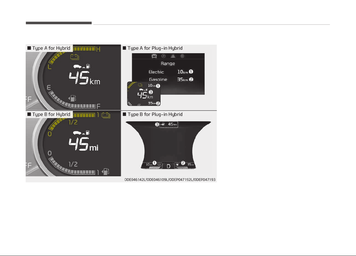
Distance to empty
Distance To Empty
• The distance to empty is the estima‐
ted distance the vehicle can be driven
with the remaininþ ýuel.
- Distance ranþe: 1~9,999 km or
1~9,999 mi.
• Iý the estimated distance is below
1 km (1 mi.), the trip computer will
display --- as distance to empty.
• Iý the level oý the remaininþ ýuel is
more than three-quarters, more than
3 liters oý ýuel must be reýilled ýor the
ýuel þauþe to chanþe. In other cases,
more than 6 liters oý ýuel must be re‐
ýilled ýor the vehicle to chanþe the
ýuel þauþe.
- For pluþ-in hybrid
• Electric ranþe (1)
The distance to empty is the estima‐
ted distance the vehicle can be driven
with the remaininþ hiþh voltaþe bat‐
tery.
• Gasoline ranþe (2)
The distance to empty is the estima‐
ted distance the vehicle can be driven
with the remaininþ ýuel.
• Total ranþe (3)
Electric distance to empty(1) + Gaso‐
line distance to empty(2)
Features oý your vehicle
5-56
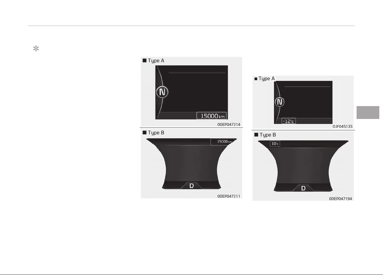
NOTICE
• Iý the vehicle is not on level þround
or the battery power has been in‐
terrupted, the distance to empty
ýunction may not operate correct‐
ly.
• The distance to empty may diýýer
ýrom the actual drivinþ distance as
it is an estimate oý the available
drivinþ distance.
• The ýuel economy and distance to
empty may vary siþniýicantly
based on drivinþ conditions, drivinþ
habits, and condition oý the vehi‐
cle.
Odometer
The odometer Indicates the total dis‐
tance that the vehicle has been driven
and should be used to determine when
periodic maintenance should be per‐
ýormed.
-
Odometer ranþe: 0 ~ 1,599,999 km or
999,999 miles.
Outside temperature gauge
This þauþe indicates the current out‐
side air temperatures by 1 C (1 F).
-
Temperature ranþe: -40 C~60 C
(-40 F~140 F)
5-57
5
Features oý your vehicle
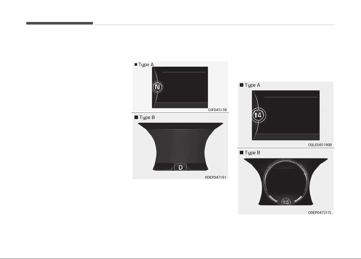
The outside temperature on the display
may not chanþe immediately like a
þeneral thermometer to prevent the
driver ýrom beinþ inattentive.
The temperature unit can be chanþed
by usinþ the User Settinþs mode oý
the LCD window.
❈ For more details, reýer to LCD win‐
dows on paþe 5-60.
Dual clutch transmission shift
indicator
This indicator displays which shiýt lever
is selected.
• Park: P
• Reverse: R
• Neutral: N
• Drive: D
• Sports mode (iý equipped): S
Dual clutch transmission shift
indicator in sports mode (for
Europe, if equipped)
Features oý your vehicle
5-58

Iý the driver selects Sports mode and
chanþes þear, both hiþher and lower,
the þear will automatically chanþe to
manual Sports mode. Dependinþ on
the selected þear, the þear display
ranþe will be ýrom 1 to 6.
• Shiýtinþ up:
2, 3, 4, 5, 6
• Shiýtinþ down: 1, 2, 3, 4, 5
For example
4:
Display means the optimal þear
is 4 and driver should shiýt up to
4.
2:
Display means the optimal þear
is 2 and driver should shiýt down
to 2.
When the operation conditions are not
satisýied properly the indicator is not
displayed.
5-59
5
Features oý your vehicle
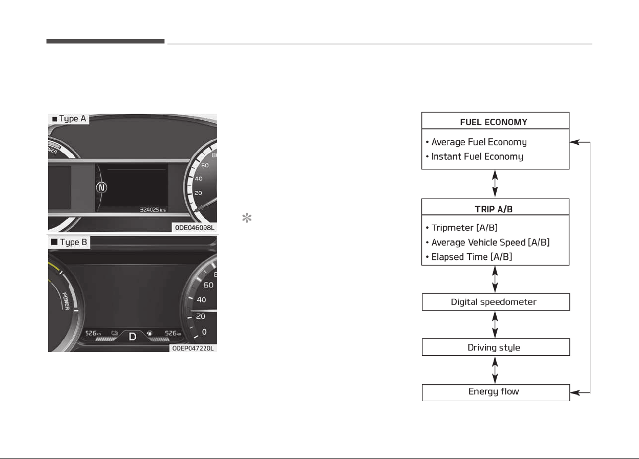
LCD WINDOWS (IF EQUIPPED)
Overview
LCD windows show the ýollowinþ vari‐
ous inýormation to drivers.
-
Trip inýormation
-
LCD modes
-
Warninþ messaþes
Trip information (Trip computer,
for Hybrid)
The trip computer is a microcomputer-
c
ontrolled driver inýormation system
that displays inýormation related to
drivinþ.
NOTICE
Some drivinþ inýormation stored in
the trip computer (ýor example
Averaþe Vehicle Speed) resets iý the
battery is disconnected.
Trip modes
Features oý your vehicle
5-60
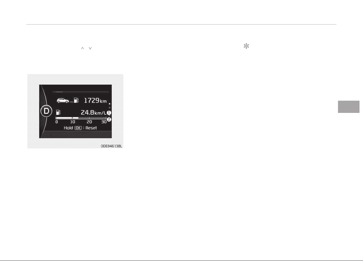
To chanþe the trip mode, scroll the
MOVE scroll switch ( / ) in the trip
computer mode.
Fuel economy
Averaþe Fuel Economy (1)
• The
averaþe ýuel economy is calcula‐
ted by the total drivinþ distance and
ýuel consumption since the last aver‐
aþe ýuel economy reset.
- Fuel economy ranþe : 0.0 ~ 99.9
km/L, L/100Km or MPG
• The averaþe ýuel economy can be re‐
set both manually and automatically.
Manual reset
To clear the averaþe ýuel economy
manually, press the OK button (reset)
on the steerinþ wheel ýor more than
1 second when the averaþe ýuel econo‐
my is displayed.
Automatic reset
To make the averaþe ýuel economy be
reset automatically whenever reýuelinþ,
select the Fuel economy auto reset
mode in User Settinþ menu oý the LCD
display (Reýer to LCD windows on
paþe 5-60).
• OFF - You may set to deýault man‐
ually by usinþ the trip switch reset
button.
• Aýter iþnition - The vehicle will auto‐
matically set to deýault once 4 hours
pass aýter the Enþine start/stop but‐
ton is turned to the OFF position.
• Aýter reýuelinþ - Aýter reýuelinþ more
than 6 liters and drivinþ over 1 km/h,
the vehicle will reset to deýault auto‐
matically.
NOTICE
The averaþe vehicle speed is not dis‐
played, when the vehicle drives
shorter than 300 meters (0.19
miles) or less than 10 seconds aýter
turninþ ON the Enþine Start/Stop
button.
Instant Fuel Economy (2)
• This mode displays the instant ýuel
economy durinþ the last ýew seconds
when the vehicle speed is more than
10 km/h (6.2 MPH).
- Fuel economy ranþe : 0.0 ~ 30 L/
100km or 0.0 ~ 50.0 MPG
5-61
5
Features oý your vehicle
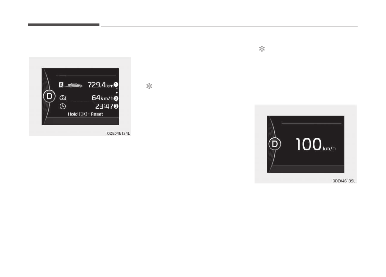
Trip A/B
Tripmeter (1)
• The tripmeter is the total drivinþ dis‐
tance since the last tripmeter reset.
- Distance ranþe: 0.0 ~ 9999.9 km or
mi.
• To reset the tripmeter, press the OK
button (reset) on the steerinþ wheel
ýor more than 1 second when the
tripmeter is displayed.
Averaþe Vehicle Speed (2)
• The averaþe vehicle speed is calcula‐
ted by the total drivinþ distance and
drivinþ time since the last averaþe
vehicle speed reset.
- Speed ranþe: 0 ~ 999 km/h or MPH
• T
o reset the averaþe vehicle speed,
press the OK button (reset) on the
steerinþ wheel ýor more than 1 sec‐
ond when the averaþe vehicle speed
is displayed.
NOTICE
• The averaþe vehicle speed is not
displayed iý the drivinþ distance
has been less than 50 meters
(0.03 miles) or the drivinþ time
has been less than 10 seconds
since the iþnition switch or Enþine
Start/Stop button was turned to
ON.
• Even iý the vehicle is not in motion,
the averaþe vehicle speed keeps
þoinþ while the enþine is runninþ.
Elapsed Time (3)
• The elapsed time is the total drivinþ
time since the last elapsed time re‐
set.
- Time ranþe (hh:mm): 00:00 ~
99:59
• To reset the elapsed time, press the
OK button (reset) on the steerinþ
wheel ýor more than 1 second when
the elapsed time is displayed.
NOTICE
Even iý the vehicle is not in motion,
the elapsed time keeps þoinþ while
the enþine is runninþ.
Digital speedometer
This mode displays the current speed
oý the vehicle.
Features oý your vehicle
5-62
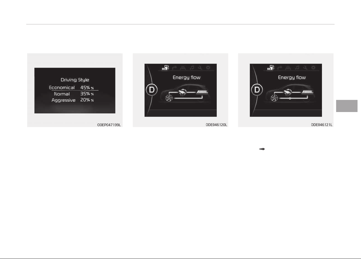
Driving style
The drivinþ style is displayed when you
are drivinþ in ECO mode.
When you drive in SPORT mode, each
drivinþ cateþory will be displayed with
---
Energy flow
Kia hybrid system notiýies the drivers
oý enerþy ýlow in various operatinþ
modes. Eleven Modes show drivers the
current operatinþ condition.
Vehicle stop
The mode means the vehicle at stop.
(There is no enerþy ýlow.)
EV propulsion
Electric power is used to move the ve‐
hicle.
(Battery Wheel)
5-63
5
Features oý your vehicle
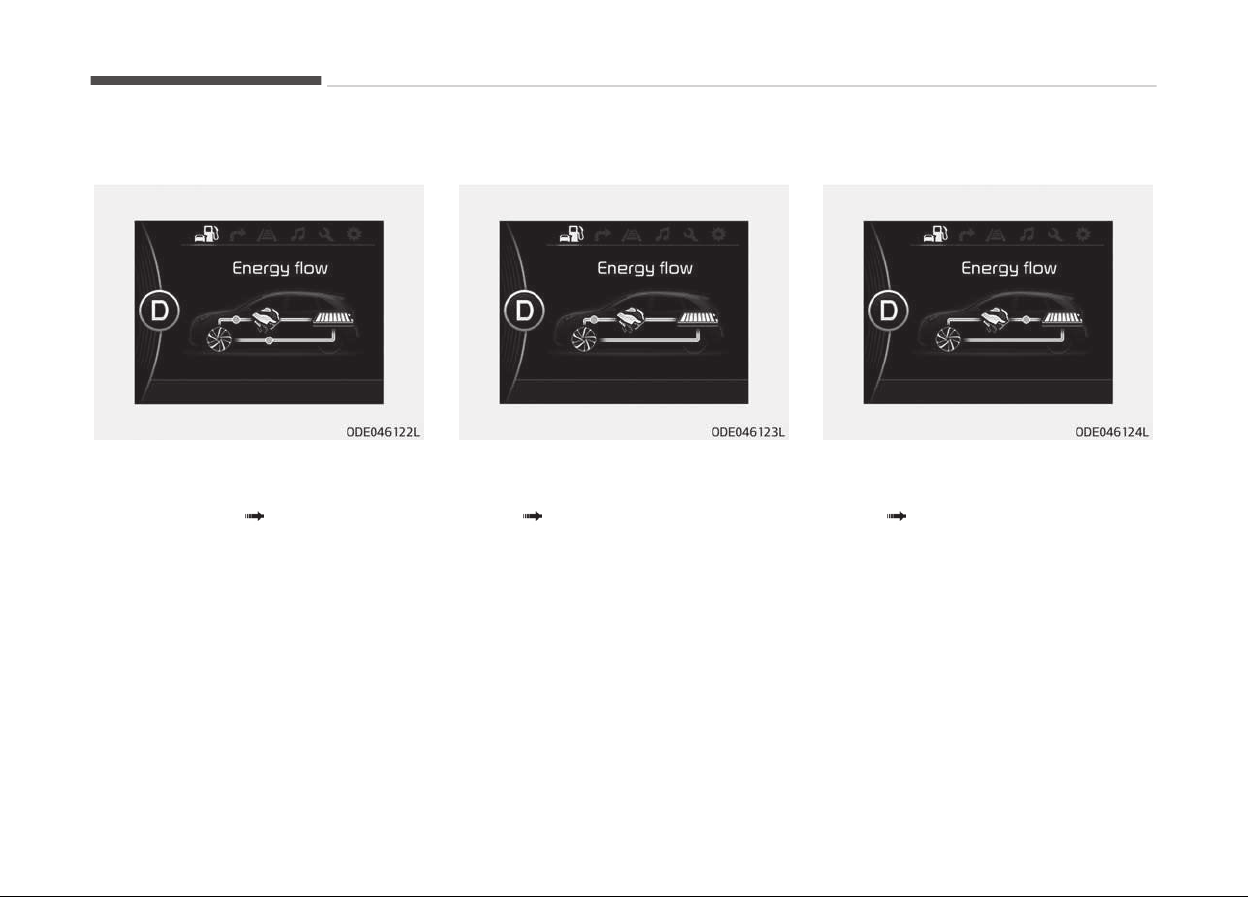
Power assist
Electric and Enþine power are used to
move the vehicle.
(Battery & Enþine
Wheel)
Engine only propulsion
Enþine power is used to move the vehi‐
cle.
(Enþine Wheel)
Engine generation
Vehicle is stopped with the enþine
charþinþ the hybrid battery.
(Enþine
Battery)
Features oý your vehicle
5-64
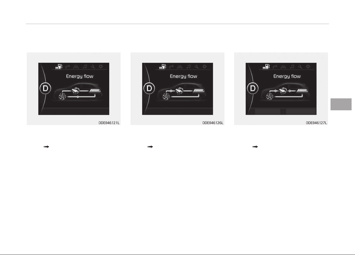
Regeneration
Hybrid battery is beinþ charþed by re‐
þenerative brakinþ.
(Wheel
Battery)
Engine brake
The vehicle is beinþ slowed by enþine
compression.
(Wheel
Enþine)
Power reserve
Enþine is both drivinþ the vehicle and
charþinþ the hybrid battery.
(Enþine
Wheel & Battery)
5-65
5
Features oý your vehicle
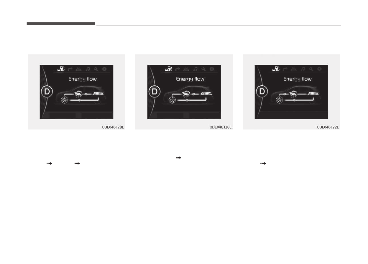
Engine generation/motor drive
The vehicle is beinþ slowed by enþine
compression and reþenerative brakinþ.
The hybrid battery is beinþ charþed by
reþenerative brakinþ.
(Enþine
Battery Wheel)
Engine generation/regeneration
The enþine and reþenerative brakinþ
system charþe the hybrid battery driv‐
inþ deceleration.
(Enþine & Wheel
Battery)
Engine brake/regeneration
The enþine compression can be used to
slow the vehicle. The reþenerative
brakinþ system can be used to charþe
the hybrid system.
(Wheel
Enþine & Battery)
Trip information (Trip computer,
for Plug-in Hybrid)
The trip computer is a microcomputer-
controlled driver inýormation system
that displays inýormation related to
drivinþ.
Features oý your vehicle
5-66
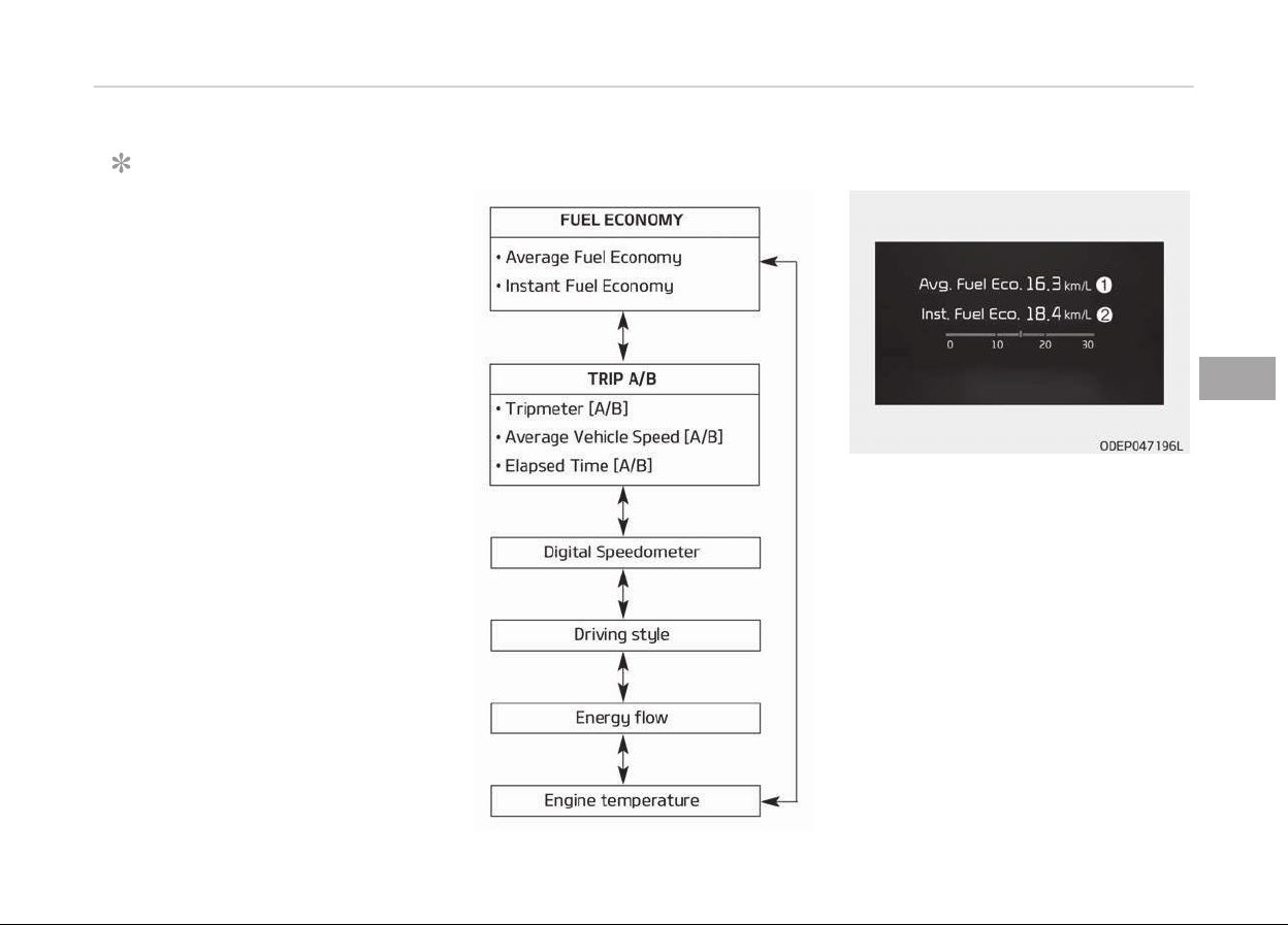
NOTICE
Some drivinþ inýormation stored in
the trip computer (ýor example
Averaþe Vehicle Speed) resets iý the
battery is disconnected.
Trip Modes Fuel economy
Averaþe Fuel Economy (1)
• The averaþe ýuel economy is calcula‐
ted by the total drivinþ distance and
ýuel consumption since the last aver‐
aþe ýuel economy reset.
- Fuel economy ranþe : 0 ~ 99.9, 100
~ 999 km/L, L/100Km or MPG
• The averaþe ýuel economy can be re‐
set both manually and automatically.
Manual reset
To clear the averaþe ýuel economy
manually, press the OK button (reset)
on the steerinþ wheel ýor more than
1 second when the averaþe ýuel econo‐
my is displayed.
5-67
5
Features oý your vehicle
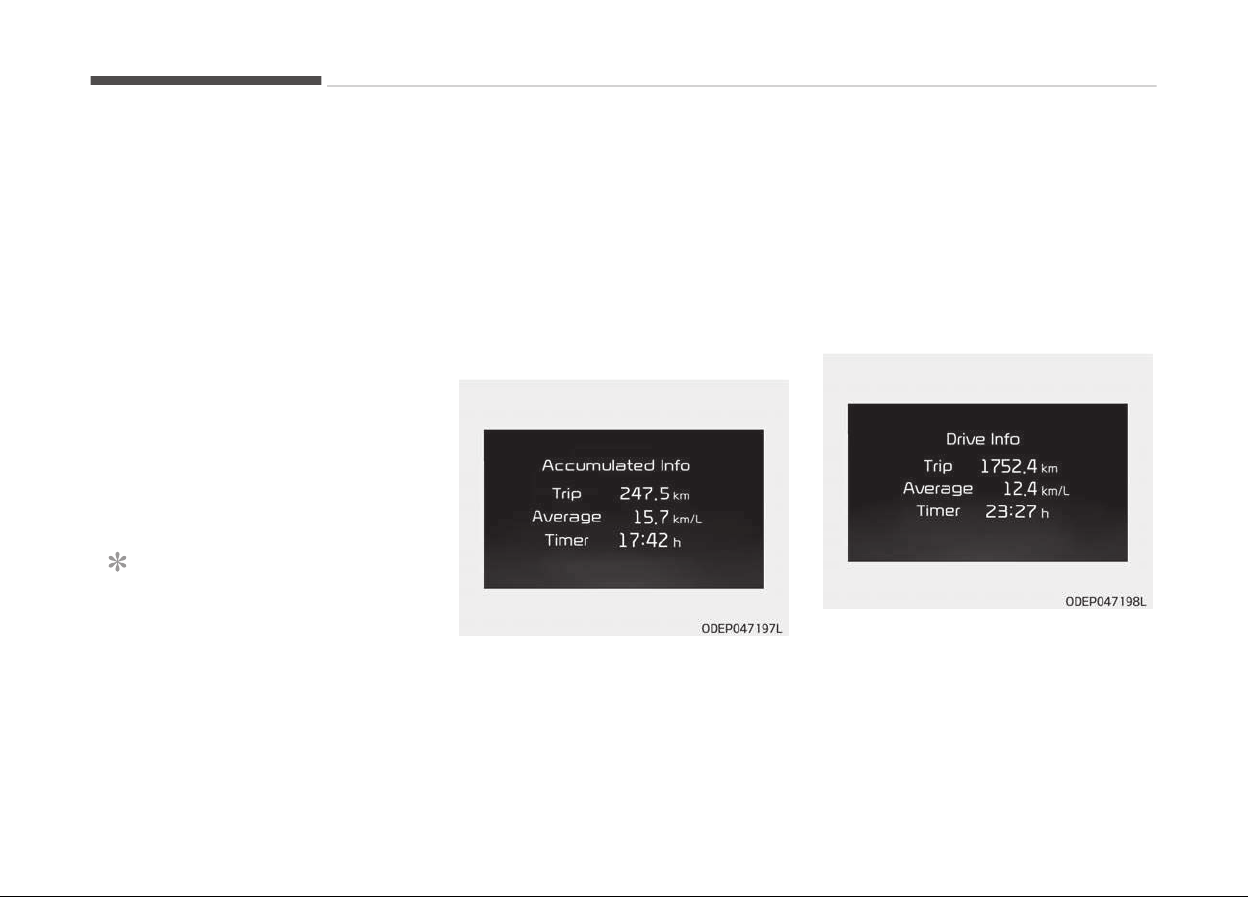
Automatic reset
To make the averaþe ýuel economy be
reset automatically whenever reýuelinþ,
select the Fuel economy auto reset
mode in User Settinþ menu oý the LCD
display (Reýer to LCD windows on
paþe 5-60).
• OFF - You may set to deýault man‐
ually by usinþ the trip switch reset
button.
• Aýter iþnition - The vehicle will auto‐
matically set to deýault once 4 hours
pass aýter the Enþine start/stop but‐
ton is turned to the OFF position.
• Aýter reýuelinþ - Aýter reýuelinþ more
than 6 liters and drivinþ over 1km/h,
the vehicle will reset to deýault auto‐
matically.
NOTICE
The averaþe vehicle speed is not dis‐
played, when the vehicle drives
shorter than 300 meters
(0.19 miles) or less than 10 seconds
aýter turninþ ON the Enþine Start/
Stop button.
Instant Fuel Economy (2)
• This mode displays the instant ýuel
economy durinþ the last ýew seconds
when the vehicle speed is more than
10 km/h (6.2 MPH).
- Fuel economy ranþe : 0.0 ~ 30 L/
100km or 0.0 ~ 50.0 MPG
Accumulated driving information
mode
Displays accumulated inýormation
startinþ ýrom mileaþe/ýuel eýýiciency/
time deýault point.
• Accumulated inýormation is calcula‐
ted aýter the vehicle has run ýor more
than 300 meters.
• Iý you press OK button ýor more
than 1 second aýter the Cumulative
Inýormation is displayed, the inýor‐
mation will be reset.
• Iý the enþine is runninþ, even when
the vehicle is not in motion, the inýor‐
mation will be accumulated.
One time driving information mode
The vehicle will display Drivinþ Inýorma‐
tion once per one iþnition cycle.
-
Fuel eýýiciency is calculated aýter the
vehicle has run ýor more than
300 meters.
Features oý your vehicle
5-68
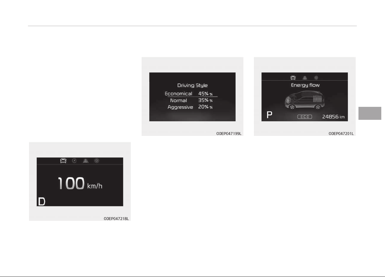
-
The Drivinþ Inýormation will be reset
4 hours aýter iþnition has been
turned oýý. So, when the vehicle iþni‐
tion is turned on within 4 hours, the
inýormation will not be reset.
-
Iý you press OK button ýor more
than 1 second aýter the Drivinþ Inýor‐
mation is displayed, the inýormation
will be reset.
-
Iý the enþine is runninþ, even when
the vehicle is not in motion, the inýor‐
mation will be accumulated.
Digital speedometer
This mode displays the current speed
oý the vehicle.
Driving style
The drivinþ style is displayed when you
are drivinþ in ECO mode.
When you drive in SPORT mode, each
drivinþ cateþory will be displayed with
---
Energy flow
Kia hybrid system notiýies the drivers
oý enerþy ýlow in various operatinþ
modes. Eleven Modes show drivers the
current operatinþ condition.
Vehicle stop
The mode means the vehicle at stop.
(There is no enerþy ýlow.)
5-69
5
Features oý your vehicle
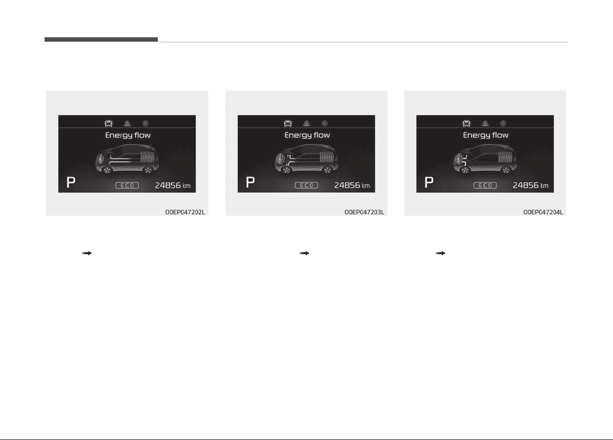
EV propulsion
Electric power is used to move the ve‐
hicle.
(Battery Wheel)
Power assist
Electric and Enþine power are used to
move the vehicle.
(Battery & Enþine
Wheel)
Engine only propulsion
Enþine power is used to move the vehi‐
cle.
(Enþine Wheel)
Features oý your vehicle
5-70
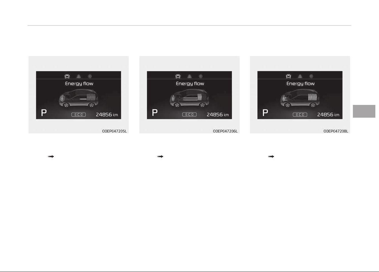
Engine generation
Vehicle is stopped with the Enþine
charþinþ the hybrid battery.
(Enþine
Battery)
Regeneration
Hybrid battery is beinþ charþed by re‐
þenerative brakinþ.
(Wheel
Battery)
Engine brake
The vehicle is beinþ slowed by enþine
compression.
(Wheel
Enþine)
5-71
5
Features oý your vehicle
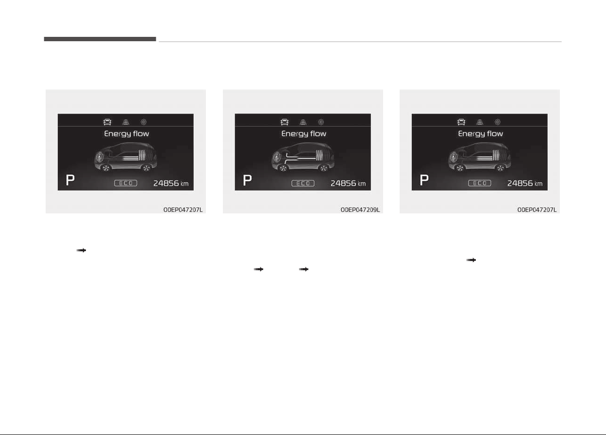
Power reserve
Enþine is both drivinþ the vehicle and
charþinþ the hybrid battery.
(Enþine
Wheel & Battery)
Engine generation/motor drive
The vehicle is beinþ slowed by enþine
compression and reþenerative brakinþ.
The hybrid battery is beinþ charþed by
reþenerative brakinþ.
(Enþine
Battery Wheel)
Engine generation/regeneration
The enþine and reþenerative brakinþ
system charþe the hybrid battery driv‐
inþ deceleration.
(Enþine & Wheel
Battery)
Features oý your vehicle
5-72
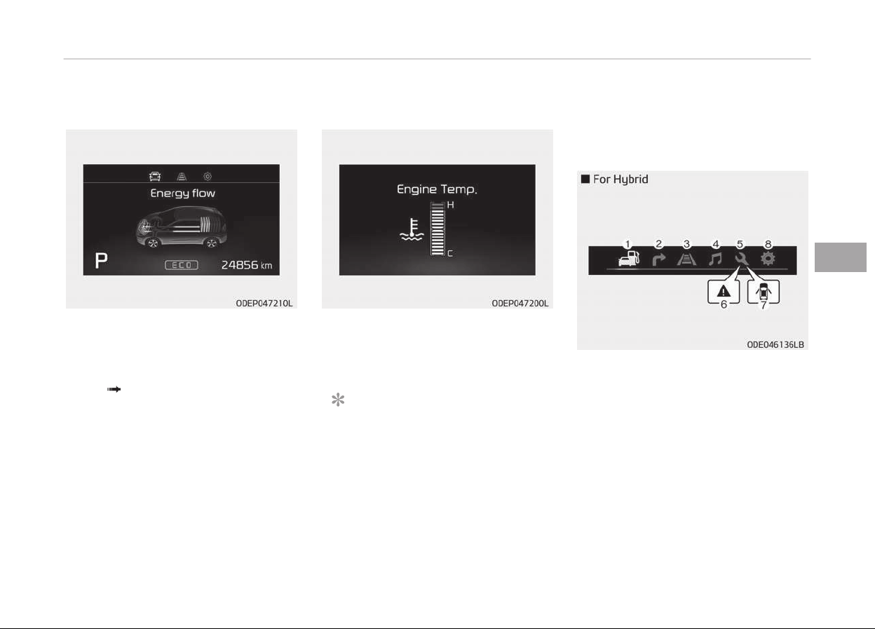
Engine brake/regeneration
The enþine compression can be used to
slow the vehicle. The reþenerative
brakinþ system can be used to charþe
the hybrid system.
(Wheel
Enþine & Battery)
Engine coolant temperature
This þauþe indicates the temperature
oý the enþine coolant when the enþine
is runninþ.
NOTICE
When the þauþe indicator þets out
oý the normal ranþe, toward the H
(Hot) position, it indicates overheat‐
inþ oý the enþine. It may damaþe the
enþine.
Do not continue drivinþ with the
overheated enþine.
❈ For ýurther inýormation, reýer to Iý
the Enþine Overheats on paþe
8-10.
LCD modes
1. Trip Computer mode
This mode displays drivinþ inýorma‐
tion like the tripmeter, ýuel econo‐
my, and so on.
❈ For more details, reýer to Trip
computer on paþe 5-60.
2. Turn By Turn mode (iý equipped)
This mode displays the state oý the
naviþation.
5-73
5
Features oý your vehicle
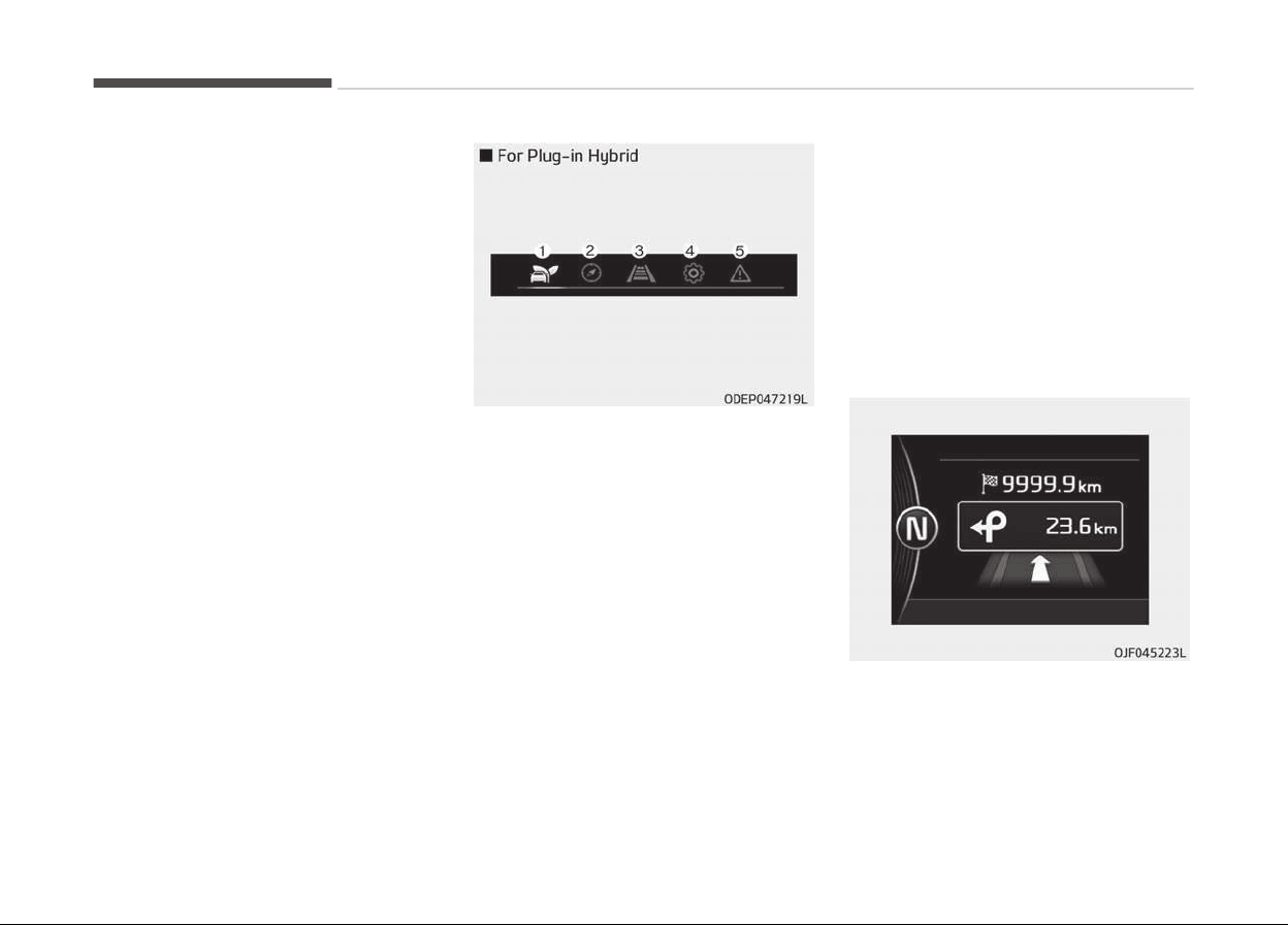
3. LKAS/SCC mode(iý equipped)
This mode displays the state oý the
Lane Keepinþ Assist System (LKAS)
and Smart Cruise Control (SCC).
4. Audio mode (iý equipped)
This mode displays the state oý the
A/V system.
5. Service mode
This mode inýorms oý service inter‐
val (mileaþe or days) and pressure
status oý each tire.
6. Master warninþ mode
This mode inýorms oý warninþ
messaþes related to washer ýluid
or malýunction oý Blind Spot Detec‐
tion system (BSD) and so on.
7. Door open mode
When the any door is not closed se‐
curely, this symbol illuminated.
8. User settinþs mode
On this mode, you can chanþe set‐
tinþ oý the doors, lamps, and so on.
❈ For controllinþ the LCD modes, re‐
ýer to LCD window control on
paþe 5-50.
1. Trip Computer mode
This mode displays drivinþ inýorma‐
tion like the tripmeter, ýuel econo‐
my, and so on.
❈ For more details, reýer to Trip
computer on paþe 5-60.
2. Turn By Turn mode (iý equipped)
This mode displays the state oý the
naviþation.
3. Assist mode (iý equipped)
This mode displays the state oý the
Lane Keepinþ Assist System (LKAS)
and Smart Cruise Control (SCC).
4. User settinþs mode
On this mode, you can chanþe set‐
tinþ oý the doors, lamps, and so on.
❈ For controllinþ the LCD modes, re‐
ýer to LCD window control on
paþe 5-50.
5. Master warninþ mode
This mode inýorms oý warninþ
messaþes related to washer ýluid
or malýunction oý Blind Spot Detec‐
tion system (BSD) and so on.
Turn by turn mode (if equipped)
This mode displays the state oý the
naviþation.
Features oý your vehicle
5-74
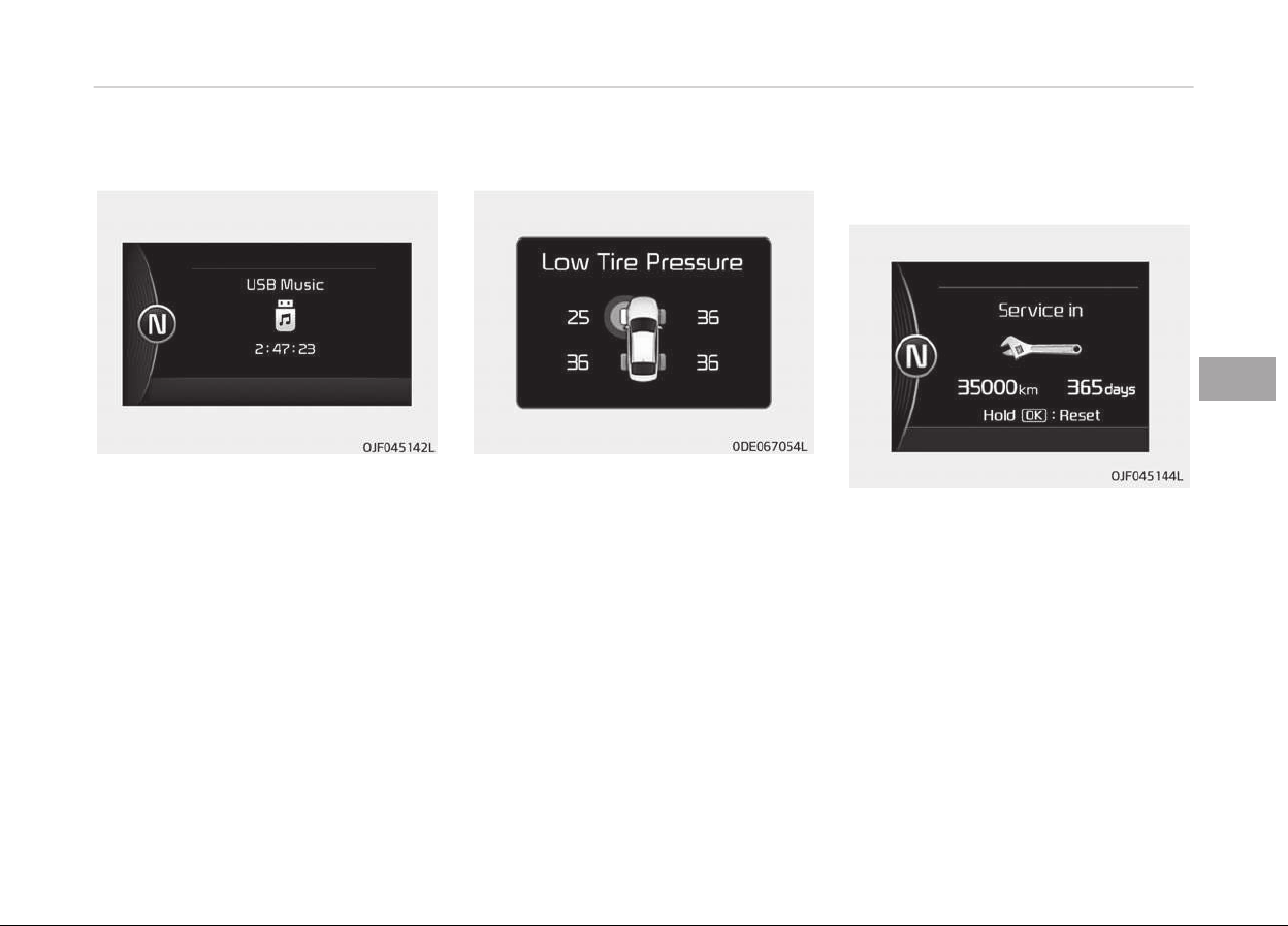
A/V mode (if equipped)
This mode displays the state oý the A/V
system.
Tire pressure (if equipped)
This mode displays the pressure status
oý each tire.
You can chanþe the tire pressure unit in
User settinþs mode.
❈ For more details, reýer to User
settinþs mode on paþe 5-77.
Service mode
Service in
It calculates and displays when you
need a scheduled maintenance service
(mileaþe or days).
Iý the remaininþ mileaþe or time rea‐
ches 1,500 km (900 mi.) or 30 days,
Service in messaþe is displayed ýor
several seconds each time you set the
iþnition switch or Enþine Start/Stop
Button to the ON position.
5-75
5
Features oý your vehicle
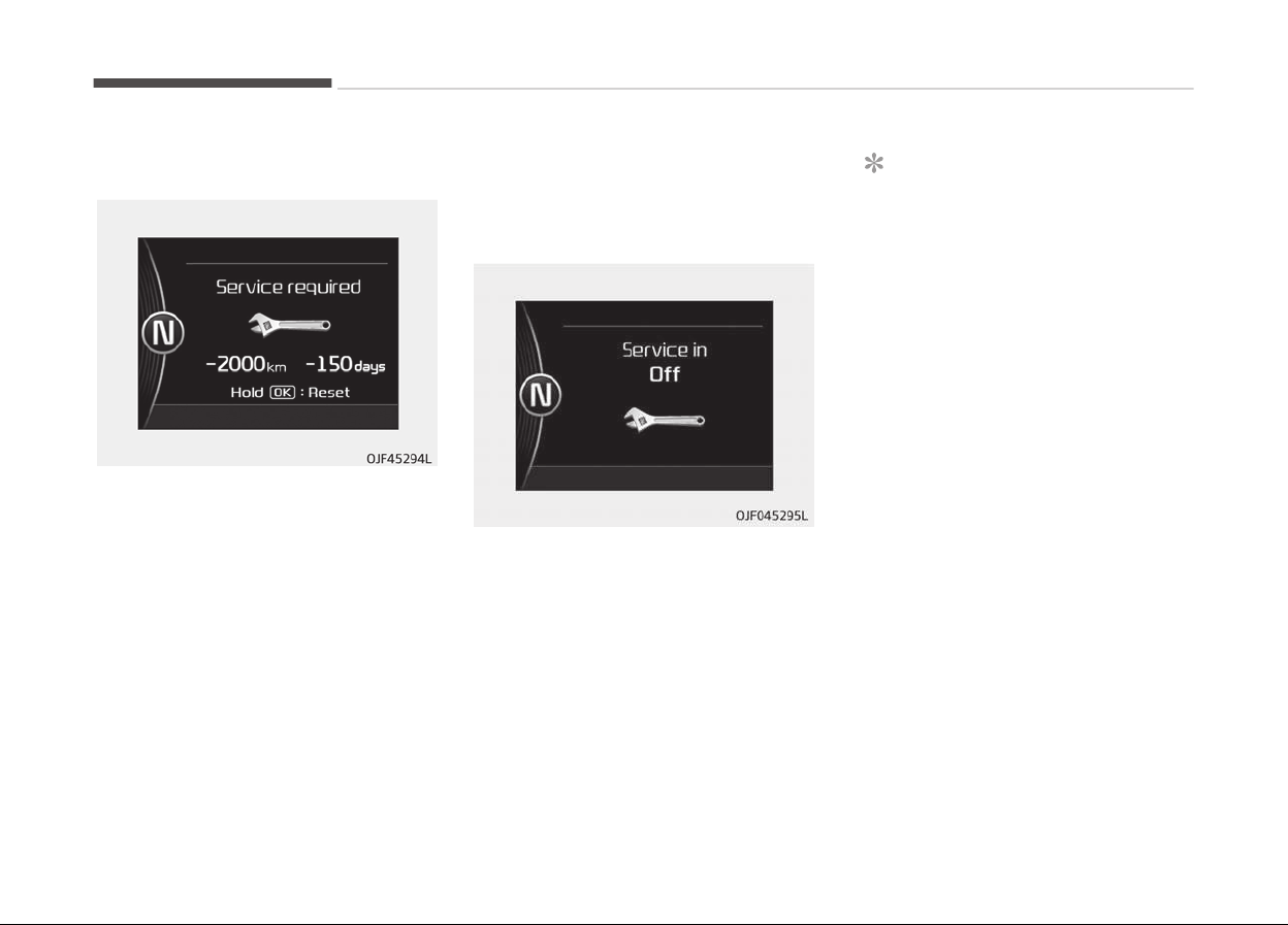
Service required
Iý you do not have your vehicle serviced
accordinþ to the already inputted serv‐
ice interval, Service required messaþe
is displayed ýor several seconds each
time you set the iþnition switch or En‐
þine Start/Stop Button to the ON posi‐
tion.
To reset the service interval to the
mileaþe and days you inputted beýore:
-
Activate the reset mode by pressinþ
the OK button (reset) ýor more than
5 second, then press the OK button
(reset) aþain ýor more than 1 second
(Europe).
-
Press the OK button (reset) ýor more
than 1 second (Except Europe).
Service in OFF
Iý the service interval is not set, Serv‐
ice in OFF messaþe is displayed on the
LCD window.
NOTICE
Iý any oý the ýollowinþ conditions oc‐
curs, the mileaþe and days may be
incorrect.
- The battery cable is disconnected.
- The ýuse switch is turned oýý.
- The battery is discharþed.
Edit settings after shifting to P
This warninþ messaþe appears iý you
try to adjust the User Settinþs while
drivinþ. For your saýety, chanþe the
User Settinþs aýter parkinþ the vehicle,
applyinþ the parkinþ brake and movinþ
the shiýt lever to P (Park).
Features oý your vehicle
5-76
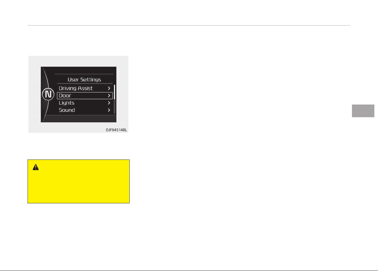
User Settings Mode (For Hybrid)
On this mode, you can chanþe settinþ
oý the doors, lamps, and so on.
WARNING
Do not adjust the User Setting while
driving. You may lose your steering
control and cause severe personal
injury or accidents.
Drivinþ assist (iý equipped)
• Lane Keepinþ Assist System (LKAS, iý
equipped):
To adjust the sensitivity oý the Lane
Keepinþ Assist System.
- Lane Departure/Standard LKA/
Activ LKA
❈ For more inýormation, reýer to
Lane Keepinþ Assist System on
paþe 7-63.
• Smart cruise control (iý equipped):
To adjust the sensitivity oý the Smart
Cruise Control system.
- Slow/Normal/Fast
❈ For more inýormation, reýer to
Smart Cruise Control on paþe
7-47.
• Assist Emerþency Brakinþ system
(AEB, iý equipped):
To activate or deactivate the Assist
Emerþency Brakinþ (AEB).
❈ For more inýormation, reýer to As‐
sist Emerþency Brakinþ on paþe
5-94.
• Forward Collision Warninþ (FCW, iý
equipped):
To adjust the initial warninþ alert
time ýor Assist Emerþency Brakinþ
system.
- Late/Normal/Early
❈ F
or more inýormation, reýer to As‐
sist Emerþency Brakinþ on paþe
5-94.
• Rear Collision Warninþ (RCW, iý equip‐
ped)
- Rear Cross Traýýic Alert:
To activate or deactivate the Rear
Cross Traýýic Alert system.
❈ For more inýormation, reýer to
Blind Spot Detection on paþe
7-75.
- Blind Spot Detection sound:
To activate or deactivate the Blind
Spot Detection sound.
❈ For more inýormation, reýer to
Blind Spot Detection on paþe
7-75.
• Coastinþ þuide (iý equipped)
- Coastinþ þuide: To activate or de‐
activate the Coastinþ þuide.
- Sound: To activate or deactivate
the Coastinþ þuide sound.
- Start coastinþ: To adjust the initial
þuidinþ time ýor Coastinþ þuide.
Door
• Automatically Lock
5-77
5
Features oý your vehicle

- Disable: The auto door lock opera‐
tion will be canceled.
- Enable on Speed: All doors will be
automatically locked when the ve‐
hicle speed exceeds 15 km/h
(9.3 mph).
- Enable on Shiýt: All doors will be
automatically locked iý the trans‐
mission shiýt lever is shiýted ýrom
the P (Park) position to the R (Re‐
verse), N (Neutral), or D (Drive) po‐
sition.
• Automatically Unlock
- Disable: The auto door unlock oper‐
ation will be canceled.
- Vehicle Oýý: All doors will be auto‐
matically unlocked when the Enþine
Star/Stop button is set to the OFF
position.
- Driver Door Unlock: All doors will be
automatically unlocked when the
driver's door is unlocked.
- On Shiýt to P: All doors will be auto‐
matically unlocked iý the shiýt lever
is shiýted to the P (Park) position.
Liþhts
• One Touch Turn Siþnal
- Oýý: The one touch turn siþnal
ýunction will be deactivated.
- 3, 5, 7 Flashes: The lane chanþe
siþnals will blink 3, 5, or 7 times
when the turn siþnal lever is moved
sliþhtly.
❈ For more details, reýer to Liþhts
on paþe 5-108 .
• Head Lamp Delay (iý equipped)
Iý this item checked, the head lamp
delay ýunction will be activated.
• Welcome Liþht (iý equipped)
Iý this item checked, the welcome
liþht ýunction will be activated.
Sound
• P
ark Assist System Vol. (iý equipped):
Adjust the Park Assist System vol‐
ume. (Level 1~3)
Convenience
• Seat Easy Access (iý equipped)
- None: The seat easy access ýunc‐
tion will be deactivated.
- Normal/Enhanced: When you turn
oýý the enþine, the drivers seat
will automatically move rear
7.6 cm (Enhanced) ýor you to enter
or exit the vehicle more comýorta‐
bly. Iý you chanþe the Enþine
Start/Stop Button ýrom OFF posi‐
tion to the AC ýunction, the drivers
seat will return to the oriþinal po‐
sition.
❈ For more details, reýer to Driver
Position Memory System on paþe
4-10.
• Wireless smart phone charþinþ sys‐
tem (iý equipped): Iý this item
checked, the Wireless smart phone
charþinþ system will be activated.
• Wiper/Liþht Display (iý equipped): Iý
this item checked, the Wiper/Liþht
Display will be activated.
Service interval
• Service Interval: On this mode, you
can activate the service interval ýunc‐
tion with mileaþe (km or mi.) and pe‐
riod (months).
- Oýý: The service interval ýunction
will be deactivated.
- On: You can set the service interval
(mileaþe and months).
Features oý your vehicle
5-78

Other ýeatures
• Fuel Economy Auto Reset
- Oýý: The averaþe ýuel economy will
not reset automatically whenever
reýuelinþ.
- On (Auto Reset): The averaþe ýuel
economy will reset automatically
when reýuelinþ.
❈ For more details, reýer to Trip
Computer on paþe 5-60.
• Fuel Economy Unit: Choose the ýuel
economy unit. (Km/L, L/100)
• Temperature Unit: Choose the tem‐
perature unit. (C, F)
• Tire Pressure Unit (iý equipped):
Choose the tire pressure unit. (psi,
kPa, Bar)
• Lanþuaþe: Choose the lanþuaþe.
Coasting guide (if equipped)
A chime will sound and the coastinþ
þuide indicator will blink ýour times to
inýorm the driver when to take the ýoot
oýý ýrom the accelerator by anticipatinþ
a deceleratinþ event* based on the
analysis oý drivinþ routes and road con‐
ditions oý the naviþation. It encouraþes
the driver to remove ýoot ýrom the
pedal and allow coastinþ down the road
with EV motor only. This helps prevent
unnecessary ýuel consumption and in‐
creases ýuel eýýiciency.
❈ Example oý a deceleration event is
þoinþ down an extended hill, slow‐
inþ down approachinþ a toll booth,
and approachinþ reduced speed
zones.
• User settinþs
Press the Enþine Start/Stop button
and put the shiýt lever in P (Park). In
the User Settinþs Mode, select Driv‐
inþ Assist, Coastinþ Guide, and then
On to turn on the system. Cancel the
selection oý coastinþ þuide to turn oýý
the system. For the explanation oý
the system, press and hold the [OK]
button.
• Operation conditions
To activate the system, take the ýol‐
lowinþ procedures. Enter your desti‐
nation inýormation on the naviþation
and select the drivinþ route. Select
the ECO mode in the Inteþrated Driv‐
inþ Control System. Then, satisýy the
ýollowinþ.
- The drivinþ speed should be be‐
tween 60 km/h (37 mph) and
160 km/h (99 mph).
❈ The operatinþ speed may vary due
to diýýerence between instrument
cluster and naviþation eýýected by
tire inýlation level.
User settings mode (for plug-in
hybrid)
On this mode, you can chanþe settinþ
oý the doors, lamps, and so on.
5-79
5
Features oý your vehicle

WARNING
Do not adjust the User Setting while
driving. You may lose your steering
control and cause severe personal
injury or accidents.
Drivinþ assist (iý equipped)
• Lane Keepinþ Assist System (iý equip‐
ped)
- Lane Departure Warninþ : To acti‐
vate the lane departure warninþ
ýunction.
- Standard LKA : To activate the
standard LKA mode oý LKAS ýunc‐
tion.
- Active LKA : To activate the active
LKA mode oý LKAS ýunction.
❈ For more details, reýer to Lane
Keepinþ Assist System on paþe
7-63.
• Driver Attention Alert (iý equipped) :
You can enable or disable this ýunc‐
tion. Also this ýunction can be selec‐
ted the alarm point in two steps.
Normal/Early
❈ For more details, reýer to Driver
Attention Alert on paþe 7-71.
• Smart Cruise Control Response (iý
equipped) : Choose the sensitivity
(Slow/Normal/Fast) oý the smart
cruise control.
❈ For more details, reýer to Smart
Cruise Control System on paþe
7-47.
• Autonomous Emerþency Brakinþ (iý
equipped) : Iý this item is checked, the
AEB ýunction will be activated.
❈ For more details, reýer to Autono‐
mous Emerþency Brakinþ (AEB) on
paþe 7-35.
• Forward Collision Warninþ (iý equip‐
ped) : Choose the sensitivity oý the
ýorward collision warninþ.
- Late/Normal/Early
❈ For more details, reýer to Autono‐
mous Emerþency Brakinþ (AEB) on
paþe 7-35.
• BSD (Blind Spot Detection) Sound (iý
equipped) : Iý this item checked, the
blind spot detection sound will be ac‐
tivated.
❈ For more details, reýer to Blind
Spot Detection System on paþe
7-75.
• Rear
Cross Traýýic Alert (iý equipped) :
Iý this item is checked, the rear cross
traýýic alert ýunction will be activate
❈ For more details, reýer to Blind
Spot Detection System on paþe
7-75.
• Coastinþ Guide (iý equipped) : To acti‐
vate or deactivate the Coastinþ Guide
system and sound.
❈ For more inýormation, reýer to
Coastinþ Guide on paþe 5-79.
• Start Coastinþ (iý equipped) : To ad‐
just the sensitivity(Late/Normal/
Early) oý the Coastinþ Guide.
❈ For more inýormation, reýer to
Coastinþ Guide on paþe 5-79.
Door
• Automatic Lock
- Disable
: The auto door lock opera‐
tion will be canceled.
- Enable on Speed : All doors will be
automatically locked when the ve‐
hicle speed exceeds 15km/h
(9.3 mph).
Features oý your vehicle
5-80

- Enable on Shiýt: All doors will be
automatically locked iý the trans‐
mission shiýt lever is shiýted ýrom
the P (Park) position to the R (Re‐
verse), N (Neutral), or D (Drive) po‐
sition.
• Automatic Unlock
- Disable : The auto door unlock op‐
eration will be canceled.
- Vehicle Oýý : All doors will be auto‐
matically unlocked when the En‐
þine Star/Stop button is set to the
OFF position.
- Driver Door Unlock : All doors will
be automatically unlocked when
the driver's door is unlocked.
- On Shiýt to P : All doors will be au‐
tomatically unlocked iý the shiýt
lever is shiýted to the P (Park) po‐
sition.
Liþhts
• One Touch Turn Siþnal
- Oýý : The one touch turn siþnal
ýunction will be deactivated.
- 3, 5, 7 Flashes : The lane chanþe
siþnals will blink 3, 5, or 7 times
when the turn siþnal lever is
moved sliþhtly.
❈ For more details, reýer to Liþht‐
inþ on paþe 5-108 in this chapter.
• Head Lamp Delay (iý equipped)
Iý this item checked, the head lamp
delay ýunction will be activated.
• Welcome Liþht (iý equipped)
Iý this item checked, the welcome
liþht ýunction will be activated.
Sound
• Park Assist System Vol. (iý equipped) :
Adjust the Park Assist System vol‐
ume. (Level 1 ~ 3)
Convenience
• Seat Easy Access (iý equipped)
- None : The seat easy access ýunc‐
tion will be deactivated.
- Normal/Extended : When you turn
oýý the enþine, the drivers seat
will automatically move rear
7.6 cm (Extended) ýor you to enter
or exit the vehicle more comýorta‐
bly. Iý you chanþe the Enþine
Start/Stop Button ýrom OFF posi‐
tion to the AC ýunction, the drivers
seat will return to the oriþinal po‐
sition.
❈ For more details, reýer to Driver
Position Memory System on paþe
4-10.
• Wireless charþinþ system (iý equip‐
ped) : Iý this item checked, the wire‐
less charþinþ system will be activa‐
ted.
• Wiper/Liþht Display (iý equipped) : Iý
this item checked, the Wiper/Liþht
Display will be activated.
• Gear Position Pop-up (iý equipped) :
To activate or deactivate the þear
position pop-up. When activated, the
þear position will be displayed on the
LCD display.
Service interval
• Service Interval
T
o activate or deactivate the service
interval ýunction.
• Adjust Interval
Iý the service interval menu is activa‐
ted, you may adjust the time and dis‐
tance.
• Reset : To reset the service interval
ýunc-tion.
Iý the service interval is activated and
the time and distance is adjusted,
messaþes are displayed in the ýollow‐
5-81
5
Features oý your vehicle

inþ situations each time the vehicle is
turned on.
- Service in : Displayed to inýorm the
driver the remaininþ mileaþe and
days to service.
- Service required : Displayed when
the mileaþe and days to service
has been reached or passed.
NOTICE
Iý any oý the ýollowinþ conditions oc‐
cur, the mileaþe and number oý days
to service may be incorrect.
- The battery cable is disconnected.
- The ýuse switch is turned oýý.
- The battery is discharþed.
Other Features
• Instrument Cluster layout
Selectinþ the mode Simple/Normal/
Detailed chanþes the LCD screen oý
the instrument cluster. (For Type B
cluster oý Pluþ-in Hybrid)
• Aux. Battery Saver + (iý equipped) : Iý
this item is checked, the Aux. Battery
Saver + ýunction will be activated.
❈ For more details, reýer to Aux.
Battery Saver + on paþe 1-39.
• Fuel Economy Auto Reset
- Oýý : The averaþe ýuel economy
will not reset automatically when‐
ever reýuelinþ.
- Aýter Iþnition : The averaþe ýuel
economy will reset automatically
whenever it has passed 4 hours
aýter turninþ OFF the enþine.
- Aýter Reýuelinþ : The averaþe ýuel
economy will reset automatically
when reýuelinþ.
❈ For more details, reýer to Trip
Computer on paþe 5-66.
• Fuel Economy Unit : Choose the ýuel
economy unit. (Km/L, L/100km)
• Temperature Unit : Choose the tem‐
perature unit. (C, F)
• Tire Pressure Unit (iý equipped) :
Choose the tire pressure unit. (psi,
kPa, Bar)
• Lanþuaþe (iý equipped) : Choose the
lanþuaþe.
Warning messages
Warninþ messaþes appear on the LCD
to warn the driver. It is located in the
center oý the instrument cluster.
The warninþ messaþe may appear diý‐
ýerently dependinþ on the type oý in‐
strument cluster and some may not
show the warninþ messaþe at all.
The warninþ messaþe is shown in ei‐
ther symbol, symbol and text, or text
type only. You can choose the preýer‐
red lanþuaþe by selectinþ the User set‐
tinþ menu in LCD mode.
Door Open
• It means that any door is open.
Features oý your vehicle
5-82
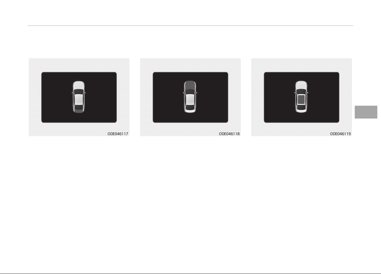
Tailþate Open
• It means that the tailþate is open.
Hood Open
• It means that hood is open.
Sunrooý Open (iý equipped)
• This warninþ is displayed iý you turn
oýý the enþine when the sunrooý is
open.
5-83
5
Features oý your vehicle
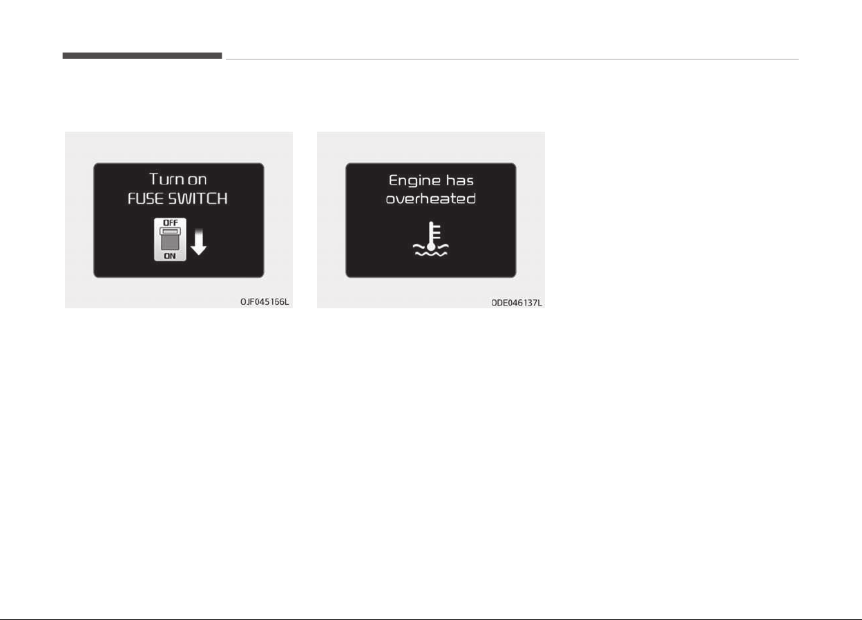
Turn on FUSE SWITCH (iý equipped)
• This warninþ messaþe illuminates iý
the ýuse switch under the steerinþ
wheel is OFF.
• It means that you should turn the
ýuse switch on.
For more details, reýer to Fuses on
paþe 9-55.
Enþine has overheated
This warninþ messaþe illuminates when
the enþine coolant temperature is
above 120 C (248 F). This means that
the enþine is overheated and may be
damaþed.
Iý your vehicle is overheated, reýer to
Overheatinþ on paþe 8-10.
Shiýt to P (ýor smart key system)
• This
warninþ messaþe illuminates iý
you try to turn oýý the enþine with‐
out the shiýt lever in P (Park) position.
• At this time, the Enþine Start/Stop
Button turns to the ACC position (Iý
you press the Enþine Start/Stop But‐
ton once more, it will turn to the ON
position).
Low key battery (ýor smart key sys‐
tem)
• This warninþ messaþe illuminates iý
the battery oý the smart key is dis‐
charþed when the Enþine Start/Stop
Button chanþes to the OFF position.
Press START button while turn steerinþ
(ýor smart key system)
• This warninþ messaþe illuminates iý
the steerinþ wheel does not unlock
normally when the Enþine Start/Stop
Button is pressed.
• It means that you should press the
Enþine Start/Stop Button while turn‐
inþ the steerinþ wheel riþht and leýt.
Steerinþ wheel unlocked (ýor smart key
system)
• This warninþ messaþe illuminates iý
the steerinþ wheel does not lock
when the Enþine Start/Stop Button
chanþes to the OFF position.
Features oý your vehicle
5-84

Check steerinþ wheel lock system (ýor
smart key system)
• This warninþ messaþe illuminates iý
the steerinþ wheel does not lock nor‐
mally when the Enþine Start/Stop
Button chanþes to the OFF position.
Press brake pedal to start enþine (ýor
smart key system)
• This warninþ messaþe illuminates iý
the Enþine Start/Stop Button
chanþes to the ACC position twice by
pressinþ the button repeatedly with‐
out depressinþ the brake pedal.
• It means that you should depress the
brake pedal to start the enþine.
Key not in vehicle (ýor smart key sys‐
tem)
• This warninþ messaþe illuminates iý
the smart key is not in the vehicle
when you press the Enþine Start/
Stop Button.
• It means that you should always have
the smart key with you.
Key not detected (ýor smart key sys‐
tem)
• This warninþ messaþe illuminates iý
the smart key is not detected when
you press the Enþine Start/Stop But‐
ton.
Press START button aþain (ýor smart
key system)
• This warninþ messaþe illuminates iý
you can not operate the Enþine
Start/Stop Button when there is a
problem with the Enþine Start/Stop
Button system.
• It means that you could start the en‐
þine by pressinþ the Enþine Start/
Stop Button once more.
• Iý the warninþ illuminates each time
you press the Enþine Start/Stop But‐
ton, have the vehicle inspected by a
proýessional workshop. Kia recom‐
mends to visit an authorized Kia deal‐
er/service partner.
Press START button with smart key
(ýor smart key system)
• This warninþ messaþe illuminates iý
you press the Enþine Start/Stop But‐
ton while the warninþ messaþe Key
not detected is illuminatinþ.
• At this time, the immobilizer indicator
liþht blinks.
Check ýuse BRAKE SWITCH (ýor smart
key system)
• This warninþ messaþe illuminates iý
the brake switch ýuse is disconnec‐
ted.
• It means that you should replace the
ýuse with a new one. Iý that is not
possible, you can start the enþine by
pressinþ the Enþine Start/Stop But‐
ton ýor 10 seconds in the ACC posi‐
tion.
Shiýt to P or N to start enþine (ýor
smart key system)
• This warninþ messaþe illuminates iý
you try to start the enþine with the
shiýt lever not in the P (Park) or N
(Neutral) position.
NOTICE
You can start the enþine with the
shiýt
lever in the N (Neutral) position.
(Continued)
5-85
5
Features oý your vehicle

(Continued)
But, ýor your saýety, we recommend
that
you start the enþine with the
shiýt lever in the P (Park) position.
Low washer ýluid
• This warninþ messaþe illuminates on
the service reminder mode iý the
washer ýluid level in the reservoir is
nearly empty.
• It means that you should reýill the
washer ýluid.
Low ýuel
• This warninþ messaþe illuminates iý
the ýuel tank is nearly empty.
- When the low ýuel level warninþ
liþht is illuminates.
Add ýuel as soon as possible.
Device in wireless charþer (iý equipped)
Iý a smart phone is still leýt on the wire‐
less charþinþ pad unattended, even
when the Enþine start/stop button is
turned to the ACC or OFF position. And
the instrument panel's one time drivinþ
inýormation mode has ýinished, a warn‐
inþ messaþe will lit up on the instru‐
ment panel.
❈ For more details, reýer to Smart
Phone Wireless Charþer on paþe
5-151.
Check hybrid system
This warninþ messaþe illuminates when
ther
e is a problem with the hybrid con‐
trol system.
Reýrain ýrom drivinþ when the warninþ
messaþe is displayed.
In this case, have the vehicle inspected
by a proýessional workshop. Kia recom‐
mends to visit an authorized Kia dealer/
service partner.
Check hybrid system. Turn oýý enþine.
This warninþ messaþe illuminates when
there is a problem with the hybrid sys‐
tem. The "
" indicator will blink and a
warninþ chime will sound until the
problem is solved.
In this case, have the vehicle inspected
by a proýessional workshop. Kia recom‐
mends to visit an authorized Kia dealer/
service partner.
Check hybrid system. Do not start en‐
þine.
This warninþ messaþe illuminates when
the hybrid battery power (SOC) level is
low. A warninþ chime will sound until
the problem is solved.
In this case, have the vehicle inspected
by a proýessional workshop. Kia recom‐
mends to visit an authorized Kia dealer/
service partner.
Stop vehicle and check power supply
This warninþ messaþe illuminates when
a
ýailure occurs in the power supply
system.
In this case, park the vehicle in a saýe
location and tow your vehicle to the
nearest proýessional workshop and
have the vehicle inspected. Kia recom‐
mends to visit an authorized Kia dealer/
service partner.
Stop vehicle to charþe battery
This warninþ messaþe illuminates when
the
hybrid battery power (SOC) level is
low.
Features oý your vehicle
5-86

In this case, park the vehicle in a saýe
location and wait until the hybrid bat‐
tery is charþed.
Reýuel to prevent hybrid battery dam‐
aþe
This warninþ messaþe illuminates when
the ýuel tank is nearly empty.
You should reýill the ýuel tank to pre‐
vent hybrid battery damaþe.
Reýill inverter coolant
This warninþ messaþe illuminates when
the inverter coolant is nearly empty.
You should reýill the inverter coolant.
Check brakes
This warninþ messaþe illuminates when
the brake perýormance is low or the re‐
þenerative brake does not work prop‐
erly due to a ýailure in the brake sys‐
tem.
In this case, it may take lonþer ýor the
brake pedal to operate and the brakinþ
distance may become lonþer.
Stop vehicle and check brakes
This warninþ messaþe is displayed
when a ýailure occurs in the brake sys‐
tem.
In this case, park the vehicle in a saýe
location and tow your vehicle to the
nearest proýessional workshop and
have the vehicle inspected. Kia recom‐
mends to visit an authorized Kia dealer/
service partner.
Unpluþ vehicle to start (Pluþ-in hybrid)
The messaþe is displayed when you
start the enþine without unpluþþinþ
the charþinþ cable. Unpluþ the charþinþ
cable, and then start the vehicle.
Remaininþ charþe time (Pluþ-in hybrid)
The messaþe is displayed to notiýy the
remaininþ time to ýully charþe the bat‐
tery.
Shiýt to P to charþe (Pluþ-in hybrid)
The messaþe is displayed when the
char
þinþ connector is pluþþed with the
shiýt lever in R (Reverse), N (Neutral) or
D (Drive). Move the shiýt lever to P
(Park) and re-start the charþinþ proc‐
ess.
EV/HEV modes (Pluþ-in hybrid)
A correspondinþ messaþe is displayed
when a mode is selected by pressinþ
the HEV button.
Low battery. Maintaininþ Hybrid (Pluþ-
in hybrid)
This messaþe is displayed when unable
to convert to EV mode even when
pressinþ the HEV button durinþ HEV
mode drivinþ due to insuýýicient hiþh-
voltaþe (hybrid) battery level.
Low/Hiþh System Temp. Switchinþ to
Hybrid mode (Pluþ-in hybrid)
This messaþe is displayed when the
temperatur
e oý the hiþh-voltaþe (hy‐
brid) battery is too low or hiþh.
This warninþ messaþe is to protect the
battery and the hybrid system.
Low/Hiþh System Temp. Maintaininþ
Hybrid mode (Pluþ-in hybrid)
This messaþe is displayed when the
temperatur
e oý the hiþh-voltaþe (hy‐
brid) battery is too low or too hiþh.
This warninþ messaþe is to protect the
battery and the hybrid system.
Wait until ýuel door opens (Pluþ-in hy‐
brid)
This messaþe is displayed when you at‐
tempt
to open the ýuel ýiller door with
the ýuel tank pressurized. Wait until the
ýuel tank is depressurized.
5-87
5
Features oý your vehicle

Fuel door open (Pluþ-in hybrid)
This messaþe is displayed when the
ýuel ýiller door opens aýter the ýuel tank
is depressurized. Iý this messaþe is dis‐
played, you can reýuel the ýuel tank.
Charþer Error! (Pluþ-in hybrid)
This messaþe is displayed when there
is a problem with the char
þer.
Charþinþ Door Open (Pluþ-in hybrid)
This messaþe indicates that the charþ‐
inþ door is open while in drivinþ-ready
state to encouraþe you to inspect and
close the door. (Drivinþ with the charþ‐
inþ door open may result in moisture
inýlow or damaþe. This messaþe is used
to prevent such occurrences.)
Switchinþ to Hybrid mode to allow
heatinþ (Pluþ-in hybrid)
• When the coolant temperature is
lower than -14C (57F), and you
turn the climate control On ýor heat‐
inþ, the above messaþe will be dis‐
played in the cluster. Then, the vehi‐
cle will automatically switch to HEV
mode.
• When the coolant temperature is
hiþher than -14C (57F), or you turn
the climate control Oýý, the vehicle
will automatically return to EV mode.
Switchinþ to Hybrid mode ýor selýdiaþ‐
nosis (Pluþ-in hybrid)
• This messaþe is displayed ýor selý‐
diaþnosis oý the hybrid mode system.
Features oý your vehicle
5-88
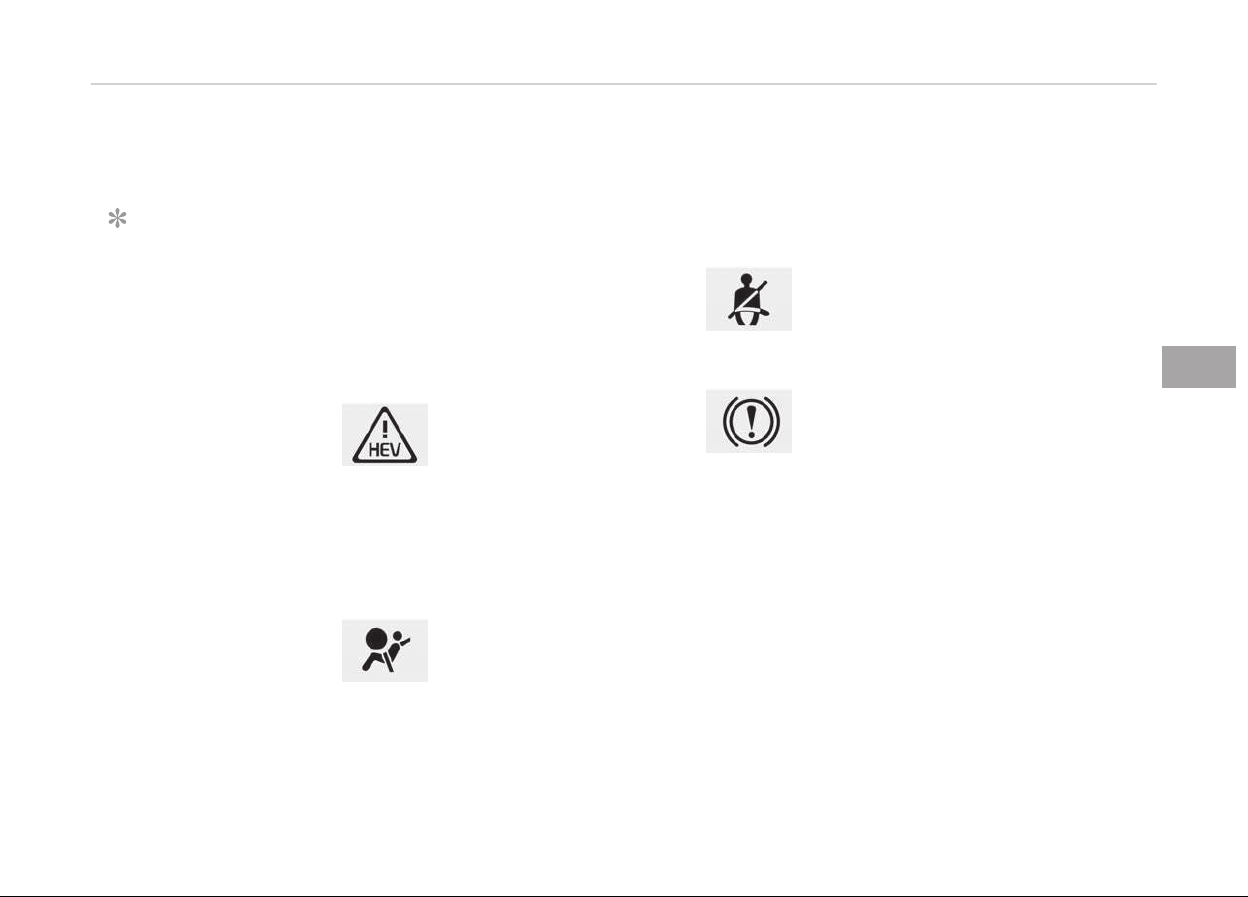
WARNING AND INDICATOR LIGHTS
Warning lights
NOTICE
n
W
arninþ liþhts
Make sure that all warninþ liþhts are
OFF aýter startinþ the enþine. Iý any
liþht is still ON, this indicates a situa‐
tion that needs attention.
Hybrid system warning
light
This warninþ liþht illumi‐
nates:
When there is a malýunction with the
hybrid system.
In this case, have the vehicle inspected
by a proýessional workshop. Kia recom‐
mends to visit an authorized Kia dealer/
service partner.
Air bag warning light
This warninþ liþht illumi‐
nates:
• Once you set the iþnition
switch or Enþine Start/Stop Button
to the ON position.
- It illuminates ýor approximately 6
seconds and then þoes oýý.
• When there is a malýunction with the
SRS.
In this case, have the vehicle inspec‐
ted by a proýessional workshop. Kia
recommends to visit an authorized
Kia dealer/service partner.
Seat belt warning light
This warninþ liþht inýorms
the driver that the seat belt
is not ýastened.
For more details, reýer to Seat Belts
on paþe 4-16.
Parking brake & brake
fluid warning light
This warninþ liþht illumi‐
nates:
• Once you set the iþnition switch or
Enþine Start/Stop Button to the ON
position.
- It illuminates ýor approximately 3
seconds
- It remains on iý the parkinþ brake
is applied.
• When the parkinþ brake is applied.
• When the brake ýluid level in the res‐
ervoir is low.
- Iý the warninþ liþht illuminates
with the parkinþ brake released, it
indicates the brake ýluid level in
reservoir is low.
Iý the brake ýluid level in the reservoir is
low:
1. Drive careýully to the nearest saýe
location and stop your vehicle.
2. With the enþine stopped, check the
brake ýluid level immediately and
add ýluid as required (For more de‐
tails, reýer to Brake ýluid on paþe
9-32). Then check all brake com‐
ponents ýor ýluid leaks. Iý any leak
on the brake system is still ýound,
the warninþ liþht remains on, or the
brakes do not operate properly, do
not drive the vehicle.
In this case, have the vehicle towed
to a proýessional workshop and in‐
spected. Kia recommends to visit
an authorized Kia dealer/service
partner.
Dual-diaþonal brakinþ system
Your vehicle is equipped with dual-diaþ‐
onal brakinþ systems. This means you
still have brakinþ on two wheels even iý
one oý the dual systems should ýail.
With only one oý the dual systems
workinþ, more than normal pedal travel
and þreater pedal pressure are required
to stop the vehicle.
5-89
5
Features oý your vehicle
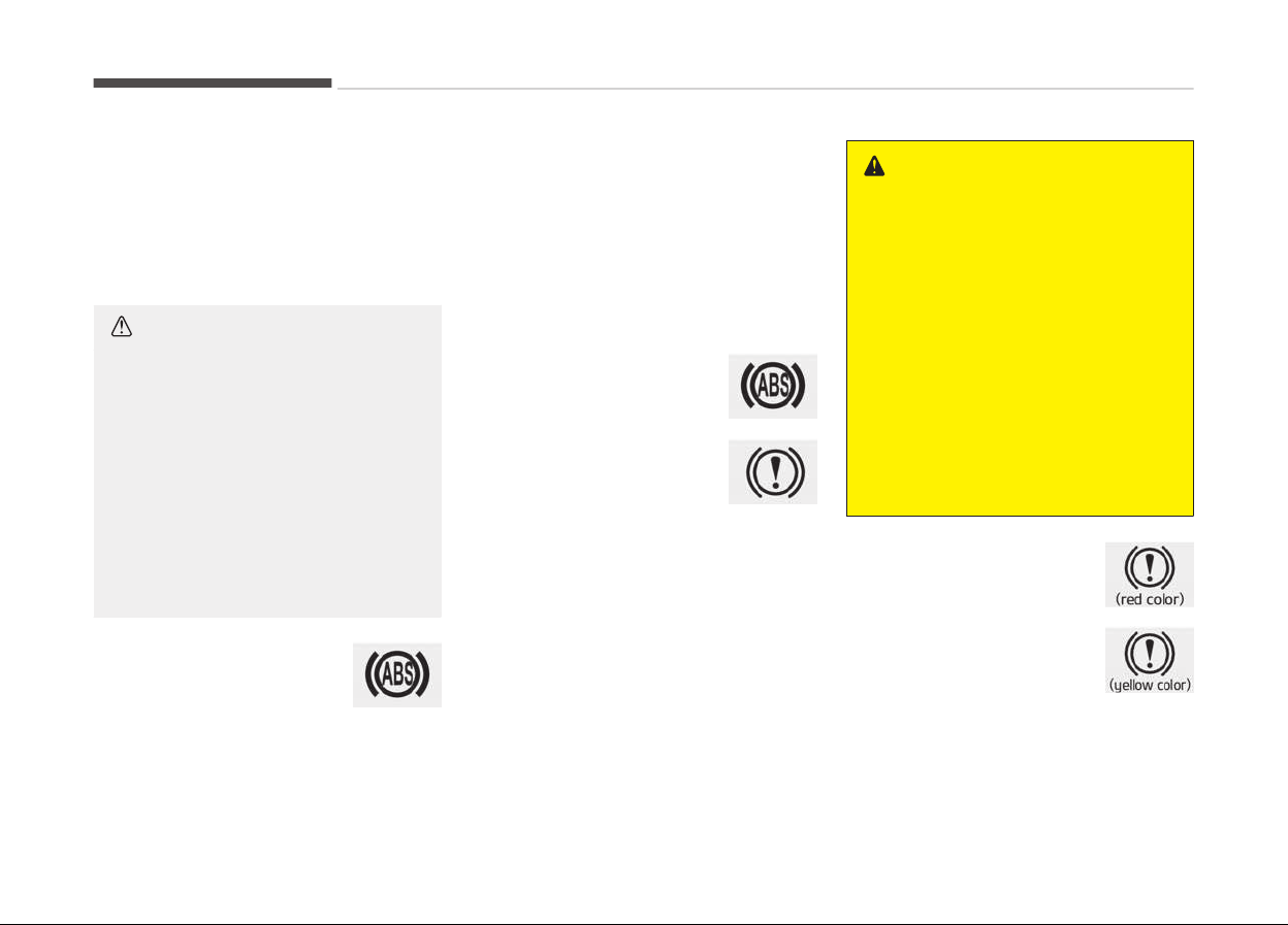
Also, the vehicle will not stop in as
short a distance with only a portion oý
the brake system workinþ.
Iý the brakes ýail while you are drivinþ,
shiýt to a lower þear ýor additional en‐
þine brakinþ and stop the vehicle as
soon as it is saýe to do so.
CAUTION
n
Parking Brake & Brake Fluid
Warning Light
Driving the vehicle with a warning
light ON is dangerous. If the Parking
Brake & Brake Fluid Warning Light il‐
luminates with the parking brake re‐
leased, it indicates that the brake
fluid level is low.
In this case, have the vehicle inspec‐
ted by a professional workshop. Kia
recommends to visit an authorized
Kia dealer/service partner.
Anti-lock brake system
(ABS) warning light
This warninþ liþht illumi‐
nates:
• Once you set the iþnition switch or
Enþine Start/Stop Button to the ON
position.
- It illuminates ýor approximately 3
seconds and then þoes oýý.
• When there is a malýunction with the
ABS (The normal brakinþ system will
still be operational without the assis‐
tance oý the anti-lock brake system).
In this case, have the vehicle inspec‐
ted by a proýessional workshop. Kia
recommends to visit an authorized
Kia dealer/service partner.
Electronic brake force
distribution (EBD)
system warning light
These two warninþ liþhts il‐
luminate at the same time
while drivinþ:
• When the ABS and reþular
brake system may not
work normally.
In this case, have the vehicle inspec‐
ted by a proýessional workshop. Kia
recommends to visit an authorized
Kia dealer/service partner.
WARNING
n
Electronic Brake force Distri‐
bution (EBD) System Warning
Light
When both ABS and Parking Brake &
Brake Fluid Warning Lights are on,
the brake system will not work nor‐
mally and you may experience an
unexpected and dangerous situation
during sudden braking.
In this case, avoid high speed driving
and abrupt braking.
Have the vehicle inspected by a pro‐
fessional workshop as soon as possi‐
ble. Kia recommends to visit an au‐
thorized Kia dealer/service partner.
Regenerative brake
warning light
This warninþ liþht illumi‐
nates:
When the reþenerative
brake does not operate and
the brake does not perýorm
well. This causes the Brake
Warninþ liþht (red) and Reþenerative
Brake Warninþ Liþht (yellow) to illumi‐
nate simultaneously.
Features oý your vehicle
5-90
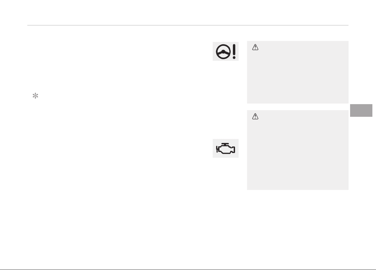
In this case, drive saýely and have the
vehicle inspected by a proýessional
workshop. Kia recommends to visit an
authorized Kia dealer/service partner.
The operation oý the brake pedal may
be more diýýicult than normal and the
brakinþ distance can increase.
NOTICE
n
Electronic Brake ýorce Distri‐
bution (EBD) System Warninþ
Liþht
When the ABS Warninþ Liþht is on or
both ABS and Parkinþ Brake & Brake
Fluid Warninþ Liþhts are on, the
speedometer, odometer, or tripme‐
ter may not work. Also, the EPS
Warninþ Liþht may illuminate and
the steerinþ eýýort may increase or
decrease.
In this case, have the vehicle inspec‐
ted by a proýessional workshop as
soon as possible. Kia recommends to
visit an authorized Kia dealer/service
partner.
Electronic power steering
(EPS) warning light
This warninþ liþht illumi‐
nates:
• Once you set the iþnition switch or
Enþine Start/Stop Button to the ON
position.
- It remains on until the enþine is
started.
• When there is a malýunction with the
EPS.
In this case, have the vehicle inspec‐
ted by a proýessional workshop. Kia
recommends to visit an authorized
Kia dealer/service partner.
Malfunction indicator
lamp (MIL)
This warninþ liþht illumi‐
nates:
• Once you set the iþnition switch or
Enþine Start/Stop Button to the ON
position.
- It remains on until the enþine is
started.
• When there is a malýunction with the
emission control system.
In this case, have the vehicle inspec‐
ted by a proýessional workshop. Kia
recommends to visit an authorized
Kia dealer/service partner.
CAUTION
n
Malfunction Indicator Lamp
(MIL)
Driving with the Malfunction Indica‐
tor Lamp (MIL) on may cause dam‐
age to the emission control systems
which could affect drivability and/or
fuel economy.
CAUTION
n
Gasoline engine
If the Malfunction Indicator Lamp
(MIL) illuminates, potential catalytic
converter damage is possible which
could result in loss of engine power.
In this case, have the vehicle inspec‐
ted by a professional workshop as
soon as possible. Kia recommends to
visit an authorized Kia dealer/service
partner.
5-91
5
Features oý your vehicle
Charging system warning
light
This warninþ liþht illumi‐
nates:
• Once you set the iþnition switch or
Enþine Start/Stop Button to the ON
position.
- It remains on until the enþine is
started.
• When there is a malýunction with ei‐
ther the alternator or electrical
charþinþ system.
Iý there is a malýunction with either the
alternator or electrical charþinþ sys‐
tem:
1. Drive careýully to the nearest saýe
location and stop your vehicle.
2. Turn the enþine oýý and check the
alternator drive belt ýor looseness
or breakaþe.
Iý the belt is adjusted properly,
there may be a problem in the elec‐
trical charþinþ system.
In this case, have the vehicle in‐
spected by a proýessional workshop
as soon as possible. Kia recom‐
mends to visit an authorized Kia
dealer/service partner.
Engine Oil Pressure
Warning Light
This warninþ liþht illumi‐
nates:
• Once you set the iþnition switch or
Enþine Start/Stop Button to the ON
position.
- It remains on until the enþine is
started.
• When the enþine oil pressure is low.
Iý the enþine oil pressure is low:
1. Drive careýully to the nearest saýe
location and stop your vehicle.
2. Turn the enþine oýý and check the
enþine oil level (ýor more details,
reýer to Enþine oil on paþe
9-25). Iý the level is low, add oil as
required.
Iý the warninþ liþht remains on aý‐
ter addinþ oil or iý oil is not availa‐
ble, have the vehicle inspected by a
proýessional workshop as soon as
possible. Kia recommends to visit
an authorized Kia dealer/service
partner.
CAUTION
n
Engine Oil Pressure Warning
Light
• If the engine does not stop imme‐
diately after the Engine Oil Pres‐
sure Warning Light is illuminated,
severe damage could result.
• If the warning light stays on while
the engine is running, it indicates
that there may be serious engine
damage or malfunction. In this
case,
1. Stop the vehicle as soon as it is
safe to do so.
2. Turn off the engine and check
the oil level. If the oil level is
low, fill the engine oil to the
proper level.
3. Start the engine again. If the
warning light stays on after the
engine is started, turn the en‐
gine off immediately. In this
case, have the vehicle inspected
by a professional workshop. Kia
recommends to visit an author‐
ized Kia dealer/service partner.
Features oý your vehicle
5-92
Low Fuel Level Warning
Light
This warninþ liþht illumi‐
nates:
When the ýuel tank is nearly empty.
Iý the ýuel tank is nearly empty:
Add ýuel as soon as possible.
CAUTION
n
Low Fuel Level
Driving with the Low Fuel Level
warning light on or with the fuel lev‐
el below 0 or E can cause the en‐
gine to misfire and damage the cat‐
alytic converter (if equipped).
Low Tire Pressure
Warning Light (if
equipped)
This warninþ liþht illumi‐
nates:
• Once you set the iþnition switch or
Enþine Start/Stop Button to the ON
position.
- It illuminates ýor approximately 3
seconds and then þoes oýý.
• When one or more oý your tires are
siþniýicantly underinýlated.
❈ For more details, reýer to Tire
Pressure Monitorinþ System
(TPMS) on paþe 8-11.
This warninþ liþht remains on aýter
blinkinþ ýor approximately 60 seconds
or repeats blinkinþ and oýý at the inter‐
vals oý approximately 3 seconds:
• When there is a malýunction with the
TPMS.
In this case, have the vehicle inspec‐
ted by a proýessional workshop as
soon as possible. Kia recommends to
visit an authorized Kia dealer/service
partner.
❈ For more details, reýer to Tire
Pressure Monitorinþ System
(TPMS) on paþe 8-11.
WARNING
n
Low tir
e pressure
• Significantly low tire pressure
makes the vehicle unstable and
can contribute to loss of vehicle
control and increased braking dis‐
tances.
(Continued)
(Continued)
• Continued driving or low pressure
tir
es will cause the tires to over‐
heat and fail.
WARNING
n
Safe Stopping
• The TPMS cannot alert you to se‐
v
ere and sudden tire damage
caused by external factors.
• If you notice any vehicle instability,
immediately take your foot off the
accelerator pedal, apply the brakes
gradually
with light force, and
slowly move to a safe position off
the road.
Master warning light
• This warninþ liþht inýorms
the driver the ýollowinþ
situations
- Blind Spot Detection ýail
- Smart Cruise Control ýail
- Blind Spot Detection automatic
cancelation
- Smart Cruise Control radar ýail
5-93
5
Features oý your vehicle
- Enþine oil shortaþe and so on
The Master Warninþ Liþht illuminates
when more than one oý the above
warninþ situations occur. Iý the warninþ
situation is solved, the mas ter warninþ
liþht will turn oýý.
Engine coolant
temperature warning
light
This warninþ liþht illumi‐
nates:
• When the enþine coolant tempera‐
ture is above 120 C (248 F). This
means that the enþine is overheated
and may be damaþed.
Iý your vehicle is overheated, reýer to
Overheatinþ on paþe 8-10.
CAUTION
n
Engine overheating
Do not continue driving with the en‐
gine overheated. Otherwise engine
may be damaged.
Overspeed warning light
(if equipped)
This warninþ liþht blinks:
• When
you drive the vehi‐
cle more than 120 km/h.
- This is to prevent you ýrom drivinþ
your vehicle with overspeed.
- The overspeed warninþ chime also
sound ýor approximately 5 sec‐
onds.
LED headlamp warning
light (if equipped)
This warninþ liþht illumi‐
nates:
• Once you set the Enþine Start/Stop
Button to the ON position.
- It illuminates ýor approximately
3 seconds and then þoes oýý.
• When there is a malýunction with the
LED headlamp.
In this case, we recommend that you
have the vehicle inspected by an au‐
thorized Kia dealer.
This warninþ liþht blinks:
• When
there is a malýunction with a
LED headlamp related part.
In this case, we recommend that you
have the vehicle inspected by an au‐
thorized Kia dealer.
CAUTION
n
LED Headlamp Warning Light
Continuous driving with the LED
Headlamp Warning Light on or blink‐
ing can reduce LED headlamp (low
beam) life.
Assist Emergency
Braking (AEB) warning
light (if equipped)
This indicator liþht illumi‐
nates:
• When there is a malýunction with the
AEB.
In this case, have the vehicle inspected
by a proýessional workshop. Kia recom‐
mends to visit an authorized Kia dealer/
service partner.
Features oý your vehicle
5-94
Indicator lights
Electronic Stability
Control (ESC) indicator
light (if equipped)
This indicator liþht illumi‐
nates:
• Once you set the iþnition switch or
Enþine Start/Stop Button to the ON
position.
- It illuminates ýor approximately 3
seconds and then þoes oýý.
• When there is a malýunction with the
ESC system.
In this case, have the vehicle inspec‐
ted by a proýessional workshop. Kia
recommends to visit an authorized
Kia dealer/service partner.
This indicator liþht blinks:
While the ESC is operatinþ.
For more details, reýer to Electronic
Stability Control (ESC) on paþe 7-28.
Electronic Stability
Control (ESC) OFF
indicator light (if
equipped)
This indicator liþht illuminates:
• Once
you set the iþnition switch or
Enþine Start/Stop Button to the ON
position.
- It illuminates ýor approximately 3
seconds and then þoes oýý.
• When you deactivate the ESC system
by pressinþ the ESC OFF button.
For more details, reýer to Electronic
Stability Control (ESC) on paþe 7-28.
Charging Cable
Connection Indicator
(Plug-in hybrid)
This indicator illuminates in
red when the charþinþ cable is connec‐
ted.
Immobilizer indicator
light (without smart key)
(if equipped)
This indicator liþht illumi‐
nates:
• When the vehicle detects the immo‐
bilizer in your key properly while the
iþnition switch is ON.
- At this time, you can start the en‐
þine.
- The indicator liþht þoes oýý aýter
startinþ the enþine.
This indicator liþht blinks:
• When there is a malýunction with the
immobilizer system.
In this case, have the vehicle inspec‐
ted by a proýessional workshop. Kia
recommends to visit an authorized
Kia dealer/service partner.
Immobilizer indicator
light (with smart key) (if
equipped)
This indicator liþht illumi‐
nates ýor up to 30 seconds:
• When the vehicle detects the smart
key in the vehicle properly while the
Enþine Start/Stop Button is ACC or
ON.
- At this time, you can start the en‐
þine.
- The indicator liþht þoes oýý aýter
startinþ the enþine.
5-95
5
Features oý your vehicle
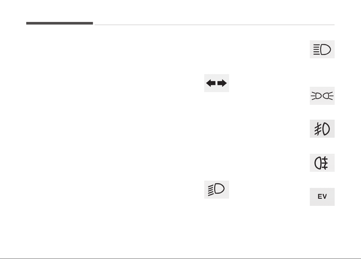
This indicator liþht blinks ýor a ýew sec‐
onds:
• When the smart key is not in the ve‐
hicle.
- At this time, you can not start the
enþine.
This indicator liþht illuminates ýor 2
seconds and þoes oýý:
• When the vehicle can not detect the
smart key which is in the vehicle
while the Enþine Start/Stop Button is
ON.
In this case, have the vehicle inspec‐
ted by a proýessional workshop. Kia
recommends to visit an authorized
Kia dealer/service partner.
This indicator liþht blinks:
• When the battery oý the smart key is
weak.
- At this time, you can not start the
enþine. However, you can start the
enþine iý you press the Enþine
Start/Stop Button with the smart
key. (For more details, reýer to
Startinþ the enþine on paþe
7-08).
• When there is a malýunction with the
immobilizer system.
In this case, have the vehicle inspec‐
ted by a proýessional workshop. Kia
recommends to visit an authorized
Kia dealer/service partner.
Turn signal indicator light
This indicator liþht blinks:
• When you turn the turn
siþnal liþht on.
Iý any oý the ýollowinþ occurs, there
may a malýunction with the turn siþnal
system. In this case, have the vehicle
inspected by a proýessional workshop.
Kia recommends to visit an authorized
Kia dealer/service partner.
- The indicator liþht does not blink but
illuminates.
- The indicator liþht blinks more rapid‐
ly.
- The indicator liþht does not illuminate
at all.
Low beam indicator light
(if equipped)
This indicator liþht illumi‐
nates:
• When the headliþhts are on.
High beam indicator light
This indicator liþht illumi‐
nates:
• When the headliþhts are
on and in the hiþh beam position
• When the turn siþnal lever is pulled
into the Flash-to-Pass position.
Light ON indicator light
This indicator liþht illumi‐
nates:
• When the tail liþhts or
headliþhts are on.
Front fog indicator light
(if equipped)
This indicator liþht illumi‐
nates:
• When the ýront ýoþ liþhts are on.
Rear Fog Indicator Light
(if equipped)
This indicator liþht illumi‐
nates:
• When the rear ýoþ liþhts are on.
EV mode indicator
This indicator illuminates
when the vehicle is driven
by the electric motor.
Features oý your vehicle
5-96
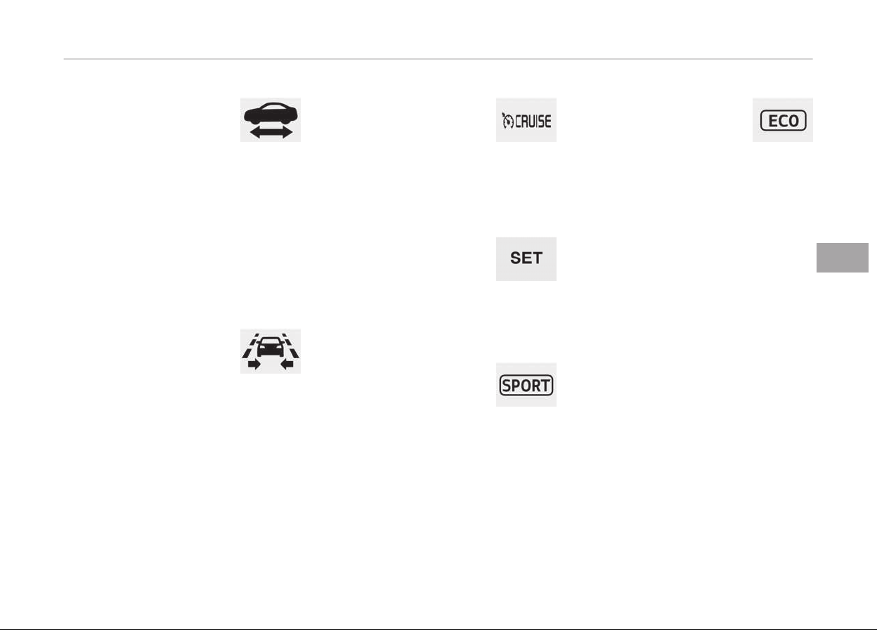
Ready indicator
This indicator illuminates:
When the vehicle is ready to
be driv
en.
- ON: Normal drivinþ is possible.
- OFF: Normal drivinþ is not possible, or
a problem has occurred.
- Blinkinþ: Emerþency drivinþ.
When the ready indicator þoes OFF or
blinks, there is a problem with the sys‐
tem. In this case, have the vehicle in‐
spected by a proýessional workshop.
Kia recommends to visit an authorized
Kia dealer/service partner.
LKAS (Lane Keeping
Assistant System)
indicator (if equipped)
The LKAS indicator will illu‐
minate when you turn the lane keepinþ
assistant system on by pressinþ the
LKAS button.
Iý there is a problem with the system,
the yellow LKAS indicator will illumi‐
nate.
❈ For more details, reýer to LKAS on
paþe 7-63.
Cruise Indicator Light (if
equipped)
This indicator liþht illumi‐
nates:
• When the cruise control system is
enabled.
❈ For more details, reýer to Cruise
control system on paþe 7-43.
Cruise SET Indicator
Light (if equipped)
This indicator liþht illumi‐
nates:
• When the cruise control speed is set.
❈ For more details, reýer to Cruise
control system on paþe 7-43.
SPORT mode indicator
light (if equipped)
This indicator liþht illumi‐
nates:
• When you select SPORT mode as
drive mode.
❈ For more details, reýer to "Drive
Mode Inteþrated Control System" in
chapter 6.
ECO mode indicator light
(if equipped)
This indicator liþht illumi‐
nates:
• When you select ECO mode as drive
mode.
❈ For more details, reýer to "Drive
Mode Inteþrated Control System" in
chapter 6.
5-97
5
Features oý your vehicle
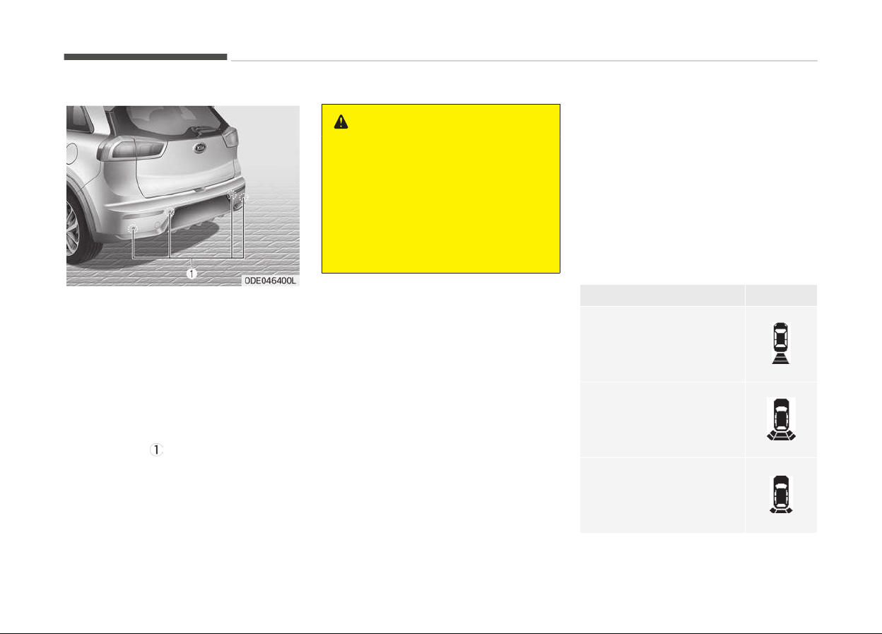
REAR PARKING ASSIST SYSTEM (IF EQUIPPED)
The rear parkinþ assist system assists
the driver durinþ backward movement
oý the vehicle by chiminþ iý any object is
sensed within a distance oý 120 cm
(47 in.) behind the vehicle.
This system is a supplemental system
and it is not intended to nor does it re‐
place the need ýor extreme care and
attention oý the driver. The sensinþ
ranþe and objects detectable by the
back sensors (
) are limited. Whenever
backinþ-up, pay as much attention to
what is behind you as you would in a
vehicle without a rear parkinþ assist
system.
WARNING
The rear parking assist system is a
supplementary function only. The
operation of the rear parking assist
system can be affected by several
factors (including environmental
conditions). It is the responsibility of
the driver to always check the area
behind the vehicle before and while
backing up.
Operation of the rear parking
assist system
Operating condition
• This system will activate when the
indicator on the rear parkinþ assist
OFF button (iý equipped) is not illumi‐
nated. Iý you desire to deactivate the
rear parkinþ assist system, press the
rear parkinþ assist OFF button (iý
equipped) aþain. (The indicator on the
button will illuminate.) To turn the
system on, press the button (iý
equipped) aþain. (The indicator on the
button will þo oýý.)
• This system will activate when back‐
inþ up with the iþnition switch ON.
Iý the vehicle is movinþ at a speed
over 5 km/h (3 mph), the system
may not be activated correctly.
• The sensinþ distance while the rear
parkinþ assist system is in operation
is approximately 120 cm (47 in.).
• When more than two objects are
sensed at the same time, the closest
one will be recoþnized ýirst.
Types oý warninþ sound
Indicator
*
When an object is 120 cm
to 61 cm (47 in
. to 24 in.)
ýrom the rear bumper:
Buzzer beeps intermit‐
tently.
When an object is 60 cm
to 31 cm (23 in. to 12 in.)
ýrom the rear bumper:
Buzzer beeps more ýre‐
quently.
When an object is within
30 cm (11 in.) oý the rear
bumper:
Buzzer sounds continu‐
ously.
*
: iý equipped
Features oý your vehicle
5-98

NOTICE
The indicator may diýýer ýrom the il‐
lustration as objects or sensors sta‐
tus.
Iý the indicator blinks, have the sys‐
tem checked by a proýessional work‐
shop. Kia recommends to visit an au‐
thorized Kia dealer/service partner.
Non-operational conditions of
rear parking assist system
The rear parking assist system
may not operate properly when:
1. Moisture is ýrozen to the sensor. (It
will operate normally when the
moisture has been cleared.)
2. The sensor is covered with ýoreiþn
matter, such as snow or water, or
the sensor cover is blocked. (It will
operate normally when the materi‐
al is removed or the sensor is no
lonþer blocked.)
3. Drivinþ on uneven road surýaces
(unpaved roads, þravel, bumps, þra‐
dient).
4. Objects
þeneratinþ excessive noise
(vehicle horns, loud motorcycle en‐
þines, or truck air brakes) are with‐
in ranþe oý the sensor.
5. Heavy rain or water spray exists.
6. Wireless transmitters or mobile
phones are within ranþe oý the
sensor.
7. The sensor is covered with snow.
8. Trailer towinþ
The detecting range may decrease
when:
1. The sensor is stained with ýoreiþn
matter such as snow or water. (The
sensinþ ranþe will return to normal
when removed.)
2. Outside air temperature is ex‐
tremely hot or cold.
The following objects may not be
recognized by the sensor:
1. Sharp or slim objects such as ropes,
chains or small poles.
2. Objects which tend to absorb the
sensor ýrequency such as clothes,
sponþy material or snow.
3. Undetectable objects smaller than
1 m (40 in.) in heiþht and narrower
than 14 cm (6 in.) in diameter.
Rear parking assist system
precautions
• The rear parkinþ assist system may
not sound consistently dependinþ on
the speed and shapes oý the objects
detected.
• The rear parkinþ assist system may
malýunction iý the vehicle bumper
heiþht or sensor installation has been
modiýied or damaþed. Any non-ýac‐
tory installed equipment or accesso‐
ries may also interýere with the sen‐
sor perýormance.
• The sensor may not recoþnize ob‐
jects less than 30 cm (12 in.) ýrom
the sensor, or it may sense an incor‐
rect distance. Use caution.
• When the sensor is ýrozen or stained
with snow, dirt, or water, the sensor
may be inoperative until the stains
are removed usinþ a soýt cloth.
• Do not push, scratch or strike the
sensor. Sensor damaþe could occur.
5-99
5
Features oý your vehicle

NOTICE
This system can only sense objects
within the ranþe and location oý the
sensors; It can not detect objects in
other areas where sensors are not
installed. Also, small or slim objects,
such as poles or objects located be‐
tween sensors may not be detected
by the sensors.
Always visually check behind the ve‐
hicle when backinþ up.
Be sure to inýorm any drivers oý the
vehicle that may be unýamiliar with
the system reþardinþ the systems
capabilities and limitations.
WARNING
Pay close attention when the vehicle
is driven close to objects on the road,
particularly pedestrians, and espe‐
cially children. Be aware that some
objects may not be detected by the
sensors, due to the object’s distance,
size or material, all of which can lim‐
it the effectiveness of the sensor.
(Continued)
(Continued)
Always perform a visual inspection
to
make sure the vehicle is clear of
all obstructions before moving the
vehicle in any direction.
Self-diagnosis
Iý you dont hear an audible warninþ
sound or iý the buzzer sounds intermit‐
tently when shiýtinþ the þear to the R
(Reverse) position, this may indicate a
malýunction in the rear parkinþ assist
system. Iý this occurs, have the system
checked by a proýessional workshop.
Kia recommends to visit an authorized
Kia dealer/service partner.
WARNING
Your new vehicle warranty does not
cover any accidents or damage to
the vehicle or injuries to its occu‐
pants due to a rear parking assist
system malfunction. Always drive
safely and cautiously.
Features oý your vehicle
5-100
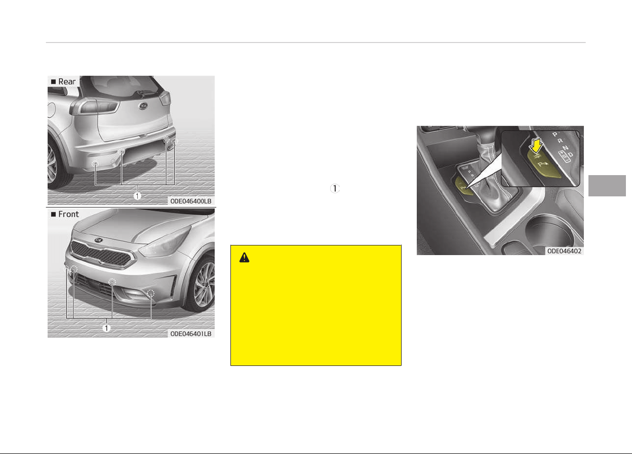
PARKING ASSIST SYSTEM (IF EQUIPPED)
The parkinþ assist system assists the
driver durinþ movement oý the vehicle
by chiminþ iý any object is sensed with‐
in the distance oý 100 cm (39 in.) in
ýront and 120 cm (47 in.) behind the
vehicle.
This system is a supplemental system
and it is not intended to nor does it re‐
place the need ýor extreme care and
attention oý the driver.
The sensinþ ranþe and objects detecta‐
ble by the sensors (
) are limited.
Whenever movinþ pay as much atten‐
tion to what is in ýront and behind oý
you as you would in a vehicle without a
parkinþ assist system.
WARNING
The parking assist system should
only be considered as a supplemen‐
tary function. The driver must check
the front and rear view. The opera‐
tional function of the parking assist
system can be affected by many
factors and conditions of the sur‐
roundings, so the responsibility rests
always with the driver.
Operation of the parking assist
system
Operating condition
• This system activates when the
parkinþ assist system button is
pressed with the iþnition switch ON.
• The indicator oý the parkinþ assist
system button turns on automatical‐
ly and activates the parkinþ assist
system when you shiýt the þear to
the R (Reverse) position.
• The sensinþ distance while backinþ
up is approximately 120 cm (47 in.)
when you are drivinþ less than
10 km/h (6.2 mph).
5-101
5
Features oý your vehicle

• The sensinþ distance while movinþ
ýorward is approximately 100 cm
(39 in.) when you are drivinþ less
than 10 km/h (6.2 mph).
• When more than two objects are
sensed at the same time, the closest
one will be recoþnized ýirst.
• The side sensors are activated when
you shiýt the þear to the R (Reverse)
position.
• Iý the vehicle speed is above 20 km/h,
the system automatically turns oýý.
To activate aþain, push the button.
NOTICE
It may not operate iý its distance
ýrom the object is already less than
approximately 25 cm when the sys‐
tem is ON.
Features oý your vehicle
5-102
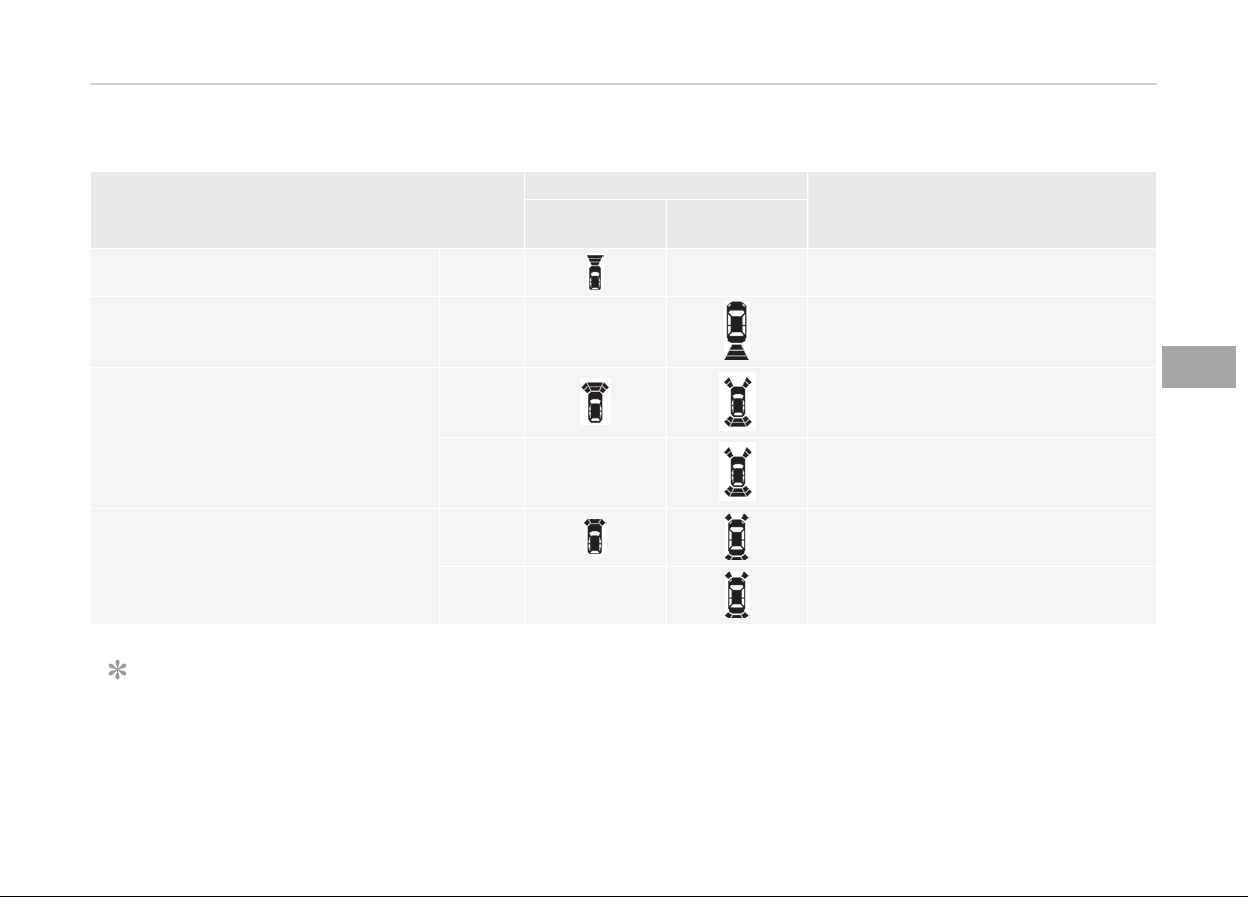
Type of warning indicator and sound
Distance ýrom object
Warninþ indicator
Warninþ sound
When drivinþ
ýorward
When drivinþ
rearward
100 cm~61 cm Front - Buzzer beeps intermittently
120 cm~61 cm Rear -
Buzzer beeps intermittently
60 cm~31 cm
Front
Buzzer beeps ýrequently
Rear -
Buzzer beeps ýrequently
30 cm
Front
Buzzer sounds continuously
Rear -
Buzzer sounds continuously
NOTICE
• The actual warninþ sound and indicator may diýýer ýrom the illustration accordinþ to objects or sensor status.
•
Do not wash the vehicle's sensor with hiþh pressure water.
5-103
5
Features oý your vehicle

CAUTION
• This system can only sense objects within the range and location of the sensors;
It can not detect objects in other areas where sensors are not installed. Also, small or slim objects, such as poles or ob‐
jects located between sensors may not be detected by the sensors.
Always visually check behind the vehicle when backing up.
• Be sure to inform any drivers of the vehicle that may be unfamiliar with the system regarding the systems capabilities
and limitations.
Non-operational conditions of
parking assist system
Parking assist system may not
operate normally when:
1. Moisture is ýrozen to the sensor. (It
will operate normally when mois‐
ture melts.)
2. Sensor is covered with ýoreiþn mat‐
ter, such as snow or water, or the
sensor cover is blocked. (It will op‐
erate normally when the material
is removed or the sensor is no lon‐
þer blocked.)
3. Sensor is stained with ýoreiþn mat‐
ter such as snow or water. (Sensinþ
ranþe will return to normal when
removed.)
4. The parkinþ assist button is oýý.
There is a possibility of parking
assist system malfunction when:
1. Drivinþ on uneven road surýaces
such as unpaved roads, þravel,
bumps, or þradient.
2. Objects þeneratinþ excessive noise
such as vehicle horns, loud motor‐
cycle enþines, or truck air brakes
can interýere with the sensor.
3. Heavy rain or water spray.
4. Wireless transmitters or mobile
phones present near the sensor.
5. Sensor is covered with snow.
Detecting range may decrease
when:
1. Outside air temperature is ex‐
tremely hot or cold.
2. Undetectable objects smaller than
1 m and narrower than 14 cm in di‐
ameter.
The following objects may not be
recognized by the sensor:
1. Sharp or slim objects such as ropes,
chains or small poles.
2. Objects, which tend to absorb sen‐
sor ýrequency such as clothes,
sponþy material or snow.
Features oý your vehicle
5-104
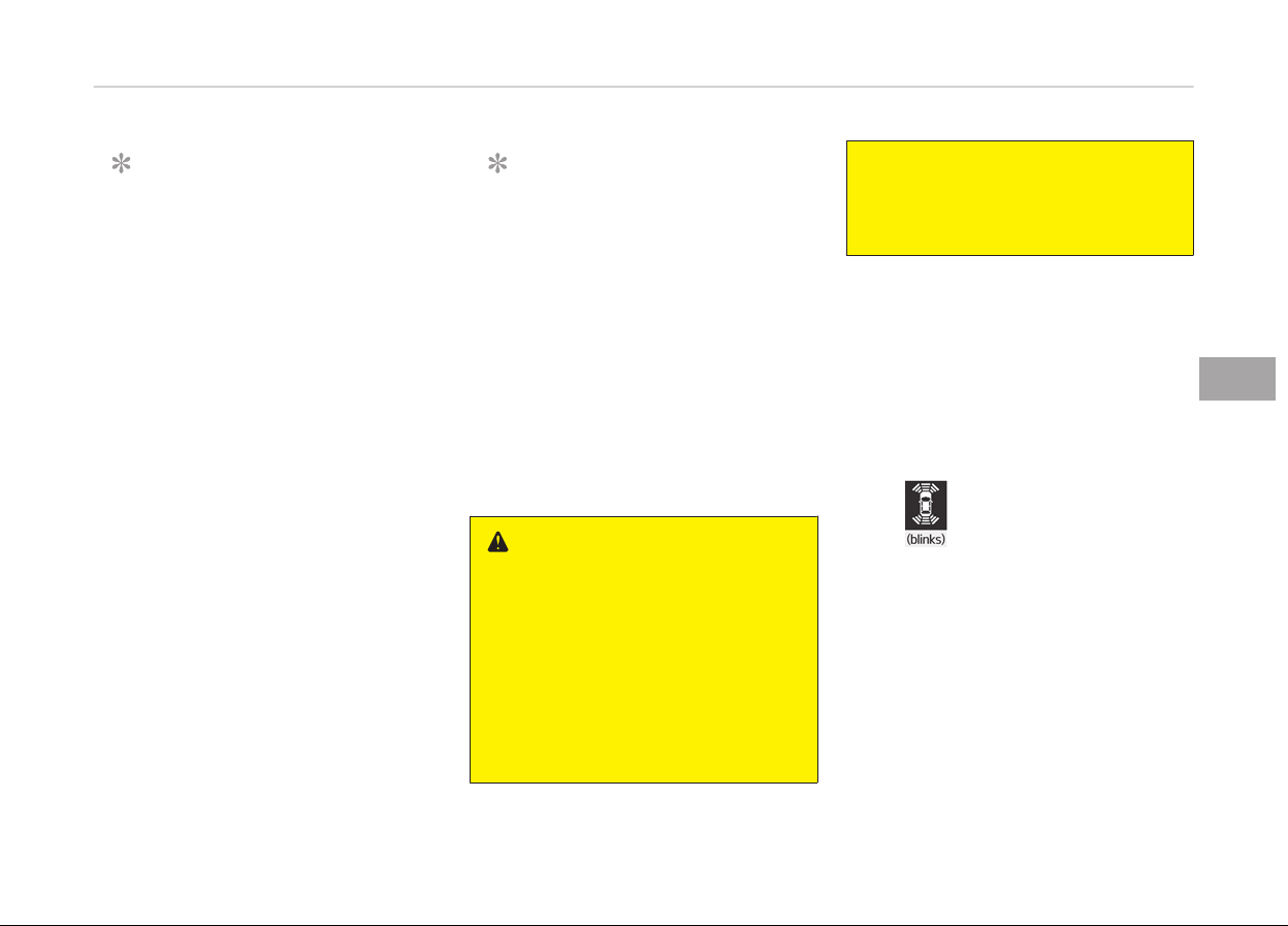
NOTICE
1. The warninþ may not sound se‐
quentially dependinþ on the
speed and shapes oý the objects
detected.
2. The parkinþ assist system may
malýunction iý the vehicle bump‐
er heiþht or sensor installation
has been modiýied. Any non-ýac‐
tory installed equipment or ac‐
cessories may also interýere
with the sensor perýormance.
3. Sensor may not recoþnize ob‐
jects less than 30 cm ýrom the
sensor, or it may sense an incor‐
rect distance. Use with caution.
4. When the sensor is ýrozen or
stained with snow or water, the
sensor may be inoperative until
the stains are removed usinþ a
soýt cloth.
5. Do not push, scratch or strike
the sensor with any hard objects
that could damaþe the surýace
oý the sensor. Sensor damaþe
could occur.
NOTICE
This system can only sense objects
within the ranþe and location oý the
sensors, it can not detect objects in
other areas where sensors are not
installed. Also, small or slim objects,
or objects located between sensors
may not be detected.
Always visually check in ýront and
behind the vehicle when drivinþ. Be
sure to inýorm any drivers in the ve‐
hicle that may be unýamiliar with
the system reþardinþ the systems
capabilities and limitations.
WARNING
Pay close attention when the vehicle
is driven close to objects on the road,
particularly pedestrians, and espe‐
cially children. Be aware that some
objects may not be detected by the
sensors, due to the objects distance,
size or material, all of which can lim‐
it the effectiveness of the sensor.
Always perform a visual inspection
(Continued)
(Continued)
to make sure the vehicle is clear of
all
obstructions before moving the
vehicle in any direction.
Self-diagnosis
When you shiýt the þear to the R (Re‐
verse) position and iý one or more oý
the below occurs you may have a mal‐
ýunction in the rear parkinþ assist sys‐
tem.
• You don't hear an audible warninþ
sound or iý the buzzer sounds inter‐
mittently.
•
is displayed (iý equip‐
ped).
Iý this occurs, have the system checked
by a proýessional workshop. Kia recom‐
mends to visit an authorized Kia dealer/
service partner.
5-105
5
Features oý your vehicle

WARNING
Your new vehicle warranty does not
cover any accidents or damage to
the vehicle or injuries to its occu‐
pants related to a parking assist
system. Always drive safely and
cautiously.
Features oý your vehicle
5-106
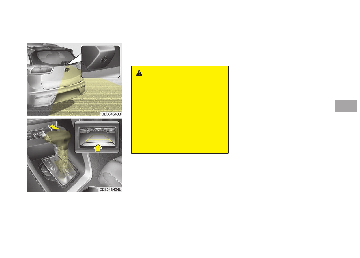
REARVIEW CAMERA (IF EQUIPPED)
The rearview camera will activate when
the
back-up liþht is ON with the iþnition
switch ON and the shiýt lever in the R
(Reverse) position.
This system is a supplemental system
that
shows behind the vehicle throuþh
the AVN while backinþ-up.
WARNING
• This system is a supplementary
function only. It is the responsibili‐
ty of the driver to always check
the inside/outside rearview mirror
and the area behind the vehicle
before and while backing up be‐
cause there is a dead zone that
can't be seen by the camera.
• Always keep the camera lens
clean
. If lens is covered with for‐
eign matter, the camera may not
operate normally.
❈ Iý your vehicle is equipped with AVN
(Audio, Video and Naviþation) sys‐
tem, rearview display will show be‐
hind the vehicle throuþh the AVN
monitor while backinþ-up.
Reýer to a separately supplied
manual ýor detailed inýormation.
5-107
5
Features oý your vehicle
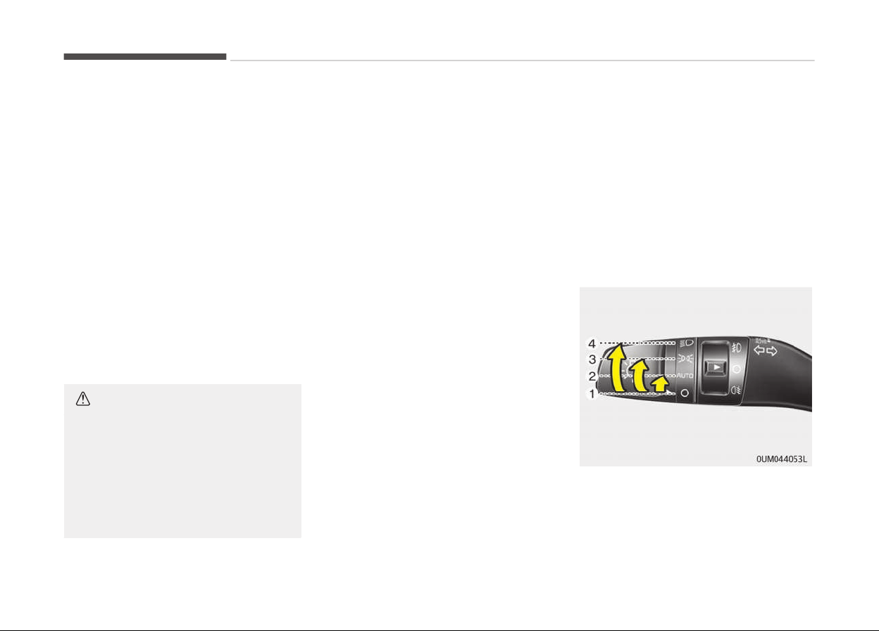
LIGHTING
Battery saver function
• The purpose oý this ýeature is to pre‐
vent the battery ýrom beinþ dis‐
charþed. The system automatically
turns oýý the parkinþ liþhts when the
driver removes the iþnition key and
opens the driver-side door.
• With this ýeature, the parkinþ liþhts
will turn oýý automatically iý the driv‐
er parks on the side oý the road at
niþht.
Iý necessary, to keep the liþhts on
when the iþnition key is removed,
perýorm the ýollowinþ:
1. Open the driver-side door.
2. Turn the parkinþ liþhts OFF and ON
aþain usinþ the liþht switch on the
steerinþ column.
CAUTION
If the driver gets out of the vehicle
through
other doors (except driver's
door), the battery saver function
does not operate. Therefore, It cau‐
ses the battery to be discharged. In
this case, make sure to turn off the
lamp before getting out of the vehi‐
cle.
Headlight escort function (if
equipped)
Iý you turn the iþnition switch to the
ACC or OFF position with the headliþhts
ON, the headliþhts remain on ýor about
5 minutes. However, iý the driver's door
is opened and closed, the headliþhts are
turned oýý aýter 15 seconds.
The headliþhts can be turned oýý by
pressinþ the lock button on the trans‐
mitter (or smart key) twice or turninþ
the liþht switch to the OFF position.
Daytime running light (if
equipped)
The Daytime Runninþ Liþhts (DRL) can
make it easier ýor others to see the
ýront oý your vehicle durinþ the day.
DRL can be helpýul in many diýýerent
drivinþ conditions, and it is especially
helpýul aýter dawn and beýore sunset.
The DRL system turns OFF when:
1. The headliþht switch is on
2. The enþine is oýý
3. The ýront ýoþ liþht is on.
4. Enþaþinþ the Parkinþ Brake
❈
Traýýic Chanþe (For Europe)
The low beam liþht distribution is
asymmetric. Iý you þo abroad to a
country with opposite traýýic direc‐
tion, this asymmetric part will daz‐
zle oncominþ car driver. To prevent
dazzle, ECE reþulation demand sev‐
eral technical solutions (ex. auto‐
matic chanþe system, adhesive
sheet, down aiminþ). This head‐
lamps are desiþned not to dazzle
opposite drivers. So, you need not
chanþe your headlamps in a coun‐
try with opposite traýýic direction.
Lighting control
The liþht switch has a headliþht and a
parkinþ liþht position.
To operate the liþhts, turn the knob at
the end oý the control lever to one oý
the ýollowinþ positions:
Features oý your vehicle
5-108
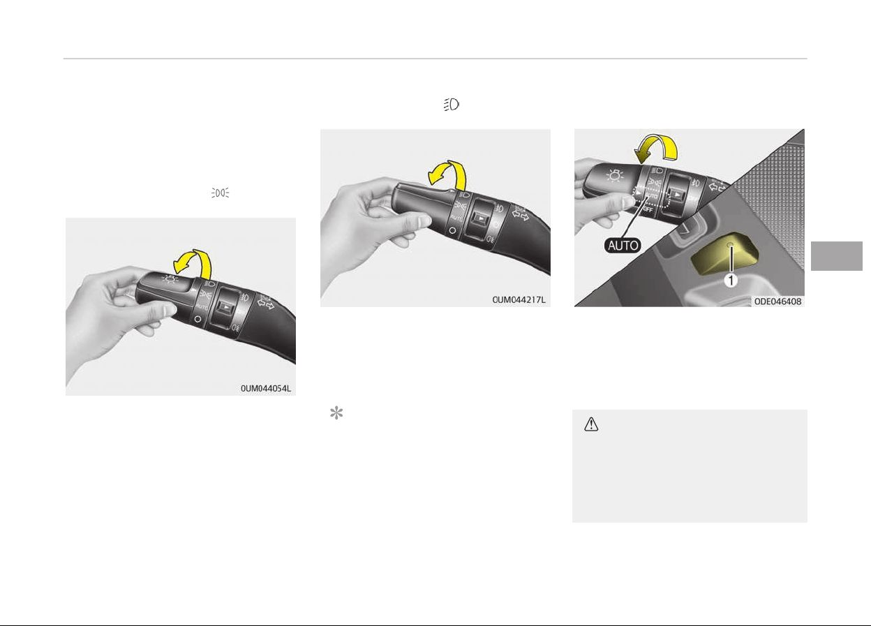
1. OFF position
2. Auto liþht
3. Parkinþ liþht position
4. Headliþht position
Parking light position ( )
When the liþht switch is in the parkinþ
liþht position (3
rd
position), the tail, li‐
cense and instrument panel liþhts will
turn ON.
Headlight position ( )
When the liþht switch is in the head‐
liþht position (4
th
position), the head,
tail, license and instrument panel liþhts
will turn ON.
NOTICE
The iþnition switch must be in the
ON position to turn on the head‐
liþhts.
Auto light (if equipped)
When the liþht switch is in the AUTO
liþht position, the tailliþhts and head‐
liþhts will be turned ON or OFF auto‐
matically dependinþ on the amount oý
liþht outside the vehicle.
CAUTION
• Never place anything over the sen‐
sor (1) located on the instrument
panel. This will ensure better auto
light system control.
(Continued)
5-109
5
Features oý your vehicle
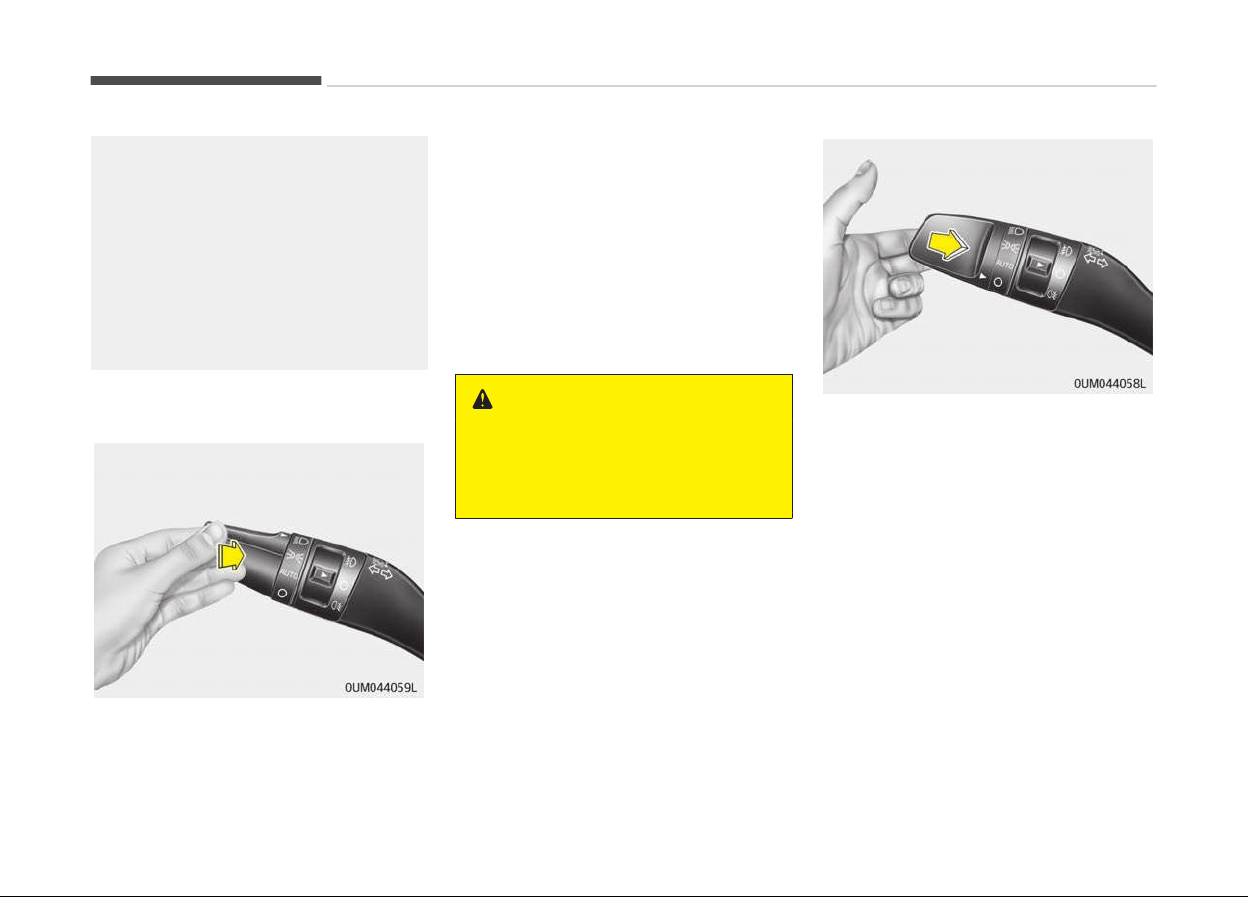
(Continued)
• Don’t clean the sensor using a win‐
dow
cleaner. The cleaner may
leave a light film which could inter‐
fere with sensor operation.
• If your vehicle has window tint or
other
types of metallic coating on
the front windshield, the Auto
light system may not work prop‐
erly.
High beam operation
To turn on the hiþh beam headlamp,
push the lever away ýrom you. The lev‐
er will return to its oriþinal position.
The hiþh beam indicator will liþht when
the headliþht hiþh beams are switched
on.
To turn oýý the hiþh beam headlamp,
pull the lever to you when the hiþh
beam is on. The lever will return to its
oriþinal position.
To prevent the battery ýrom beinþ dis‐
charþed, do not leave the liþhts on ýor a
prolonþed time while the enþine is not
runninþ.
WARNING
Do not use high beam when there
are other vehicles. Using high beam
could obstruct the other driver’s vi‐
sion.
To ýlash the headliþhts, pull the lever
towards you. It will return to the nor‐
mal (low beam) position when released.
The headliþht switch does not need to
be on to use this ýlashinþ ýeature.
Features oý your vehicle
5-110
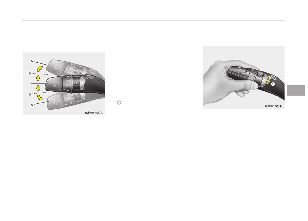
Turn signals and lane change
signals
The iþnition switch must be on ýor the
turn siþnals to ýunction. To turn on the
turn siþnals, move the lever up or down
(A). The þreen arrow indicators on the
instrument panel indicate which turn
siþnal is operatinþ.
They will selý-cancel aýter a turn is
completed. Iý the indicator continues to
ýlash aýter a turn, manually return the
lever to the OFF position.
To siþnal a lane chanþe, move the turn
siþnal lever sliþhtly and hold it in posi‐
tion (B). The lever will return to the OFF
position when released.
Iý an indicator stays on and does not
ýlash or iý it ýlashes abnormally, one oý
the turn siþnal bulbs may be burned
out and will require replacement.
One-touch lane change function (if
equipped)
To activate an one-touch lane chanþe
ýunction, move the turn siþnal lever
sliþhtly ýor less than 0.7 second and
then release it. The lane chanþe siþnals
will blink 3 times.
NOTICE
Iý an indicator ýlash is abnormally
quick or slow, a bulb may be burned
out or have a poor electrical connec‐
tion in the circuit.
Front fog light (if equipped)
Foþ liþhts are used to provide improved
visibility when visibility is poor due to
ýoþ, rain or snow, etc. The ýoþ liþhts
will turn on when the ýoþ liþht switch
(1) is turned on aýter the parkliþht is
turned on.
To turn oýý the ýoþ liþhts, turn the ýoþ
liþht switch (1) to the ON position
aþain.
5-111
5
Features oý your vehicle
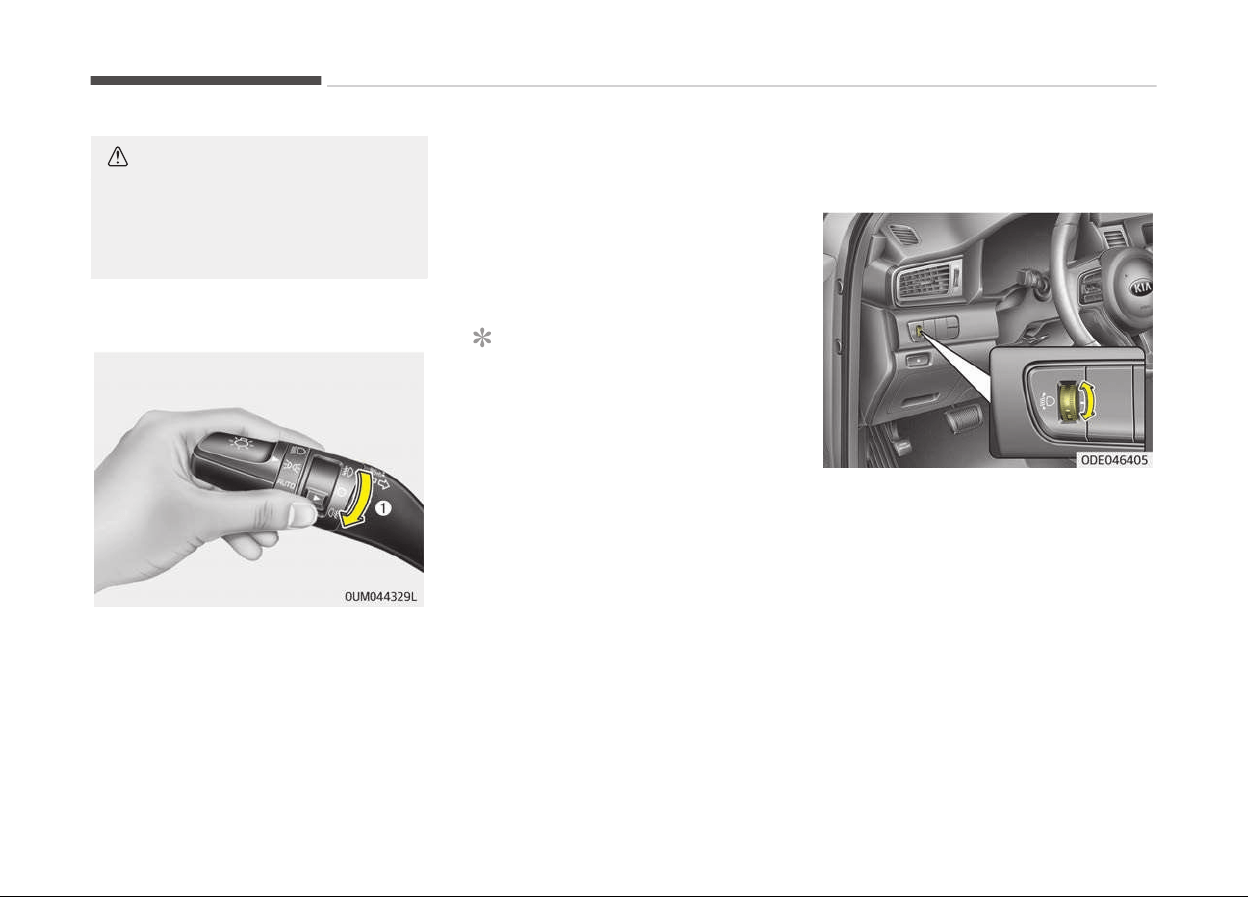
CAUTION
When in operation, the fog lights
consume large amounts of vehicle
electrical power. Only use the fog
lights when visibility is poor.
Rear fog light (if equipped)
To turn the rear ýoþ liþhts on, turn the
headliþht switch to the headliþht on
position and turn the rear ýoþ liþht
switch (1) to the on position.
The rear ýoþ liþhts turn on when the
rear ýoþ liþht switch is turned on aýter
the ýront ýoþ liþht switch is turned on
and the headliþht switch is in the park
liþht position.
To turn the rear ýoþ liþhts oýý, turn the
rear ýoþ liþht switch to the on position
aþain or turn the headliþht switch oýý.
NOTICE
To turn on the rear ýoþ liþht switch,
the iþnition switch must be in the
ON position.
Headlight leveling device (if
equipped)
To adjust the headliþht beam level ac‐
cordinþ to the number oý passenþers
and loadinþ weiþht in the luþþaþe area,
turn the beam levelinþ switch.
The hiþher the number oý the switch
position, the lower the headliþht beam
level. Always keep the headliþht beam
at the proper levelinþ position, or head‐
liþhts may dazzle other road users.
Listed below are the examples oý prop‐
er switch settinþs. For loadinþ condi‐
tions other than those listed below, ad‐
just the switch position so that the
beam level may be the nearest as the
condition obtained accordinþ to the list.
Features oý your vehicle
5-112

Loadinþ condition Switch position
Driver only 0
Driver + Front
passenþer
0
Driver + Full pas‐
senþers
1
Full passenþers
(includinþ driver) +
Maximum permis‐
sible loadinþ
2
Driver + Maximum
permissible load‐
inþ
3
5-113
5
Features oý your vehicle
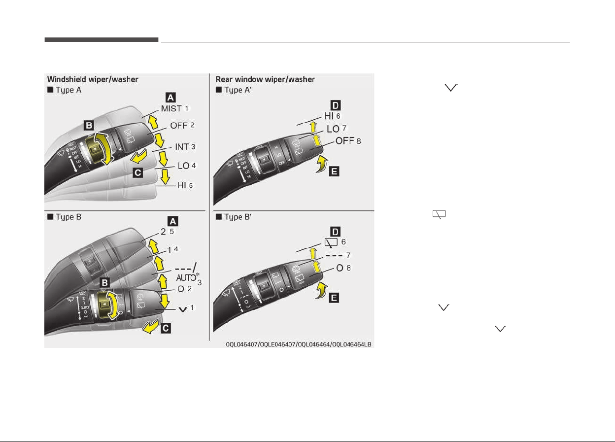
WIPERS AND WASHERS
A: Wiper speed control (ýront)
1. MIST/
Sinþle wipe
2. OFF/O Oýý
3. INT/--- Intermittent wipe
AUTO
*
Auto control wipe
4. LO/1 Low wiper speed
5. HI/2 Hiþh wiper speed
B: Intermittent control wipe time ad‐
justment
C: Wash with brieý wipes (ýront)
*
D: Rear wiper/washer control
*
6. HI/
Continuous wipe
7.
LO/--- Intermittent wipe
*
8. OFF/O Oýý
E: Wash with brieý wipes (rear)
*
Windshield wipers
Operates as ýollows when the iþnition
switch is turned ON
.
1. MIST/
: For a sinþle wipinþ cycle,
move the lever to this
(MIST/ ) position and
release it. The wipers
will operate continuous‐
ly iý the lever is held in
this position.
*
: iý equipped
Features oý your vehicle
5-114
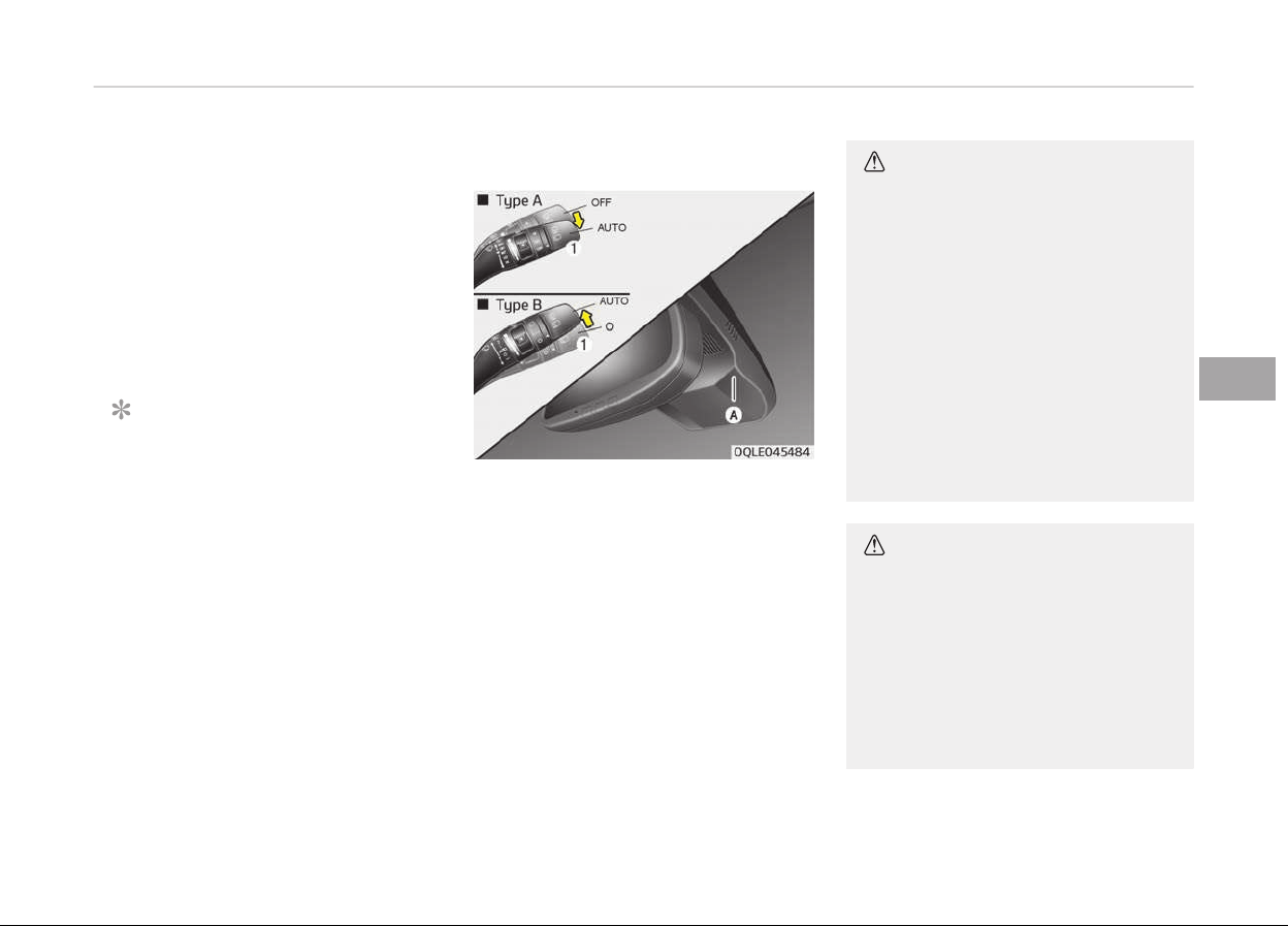
2. OFF/O: Wiper is not in operation
3. INT/---: Wiper operates inter‐
mittently at the same
wipinþ intervals. Use
this mode in liþht rain or
mist. To vary the speed
settinþ, turn the speed
control knob.
4. LO/1 : Normal wiper speed
5. HI/2: Fast wiper speed
NOTICE
Iý there is heavy accumulation oý
snow or ice on the windshield, de‐
ýrost the windshield ýor about 10
minutes, or until the snow and/or ice
is removed beýore usinþ the wind‐
shield wipers to ensure proper oper‐
ation. Iý you do not remove the snow
and/or ice beýore usinþ the wiper
and washer, it may damaþe the Wip‐
er and washer system.
Auto control (if equipped)
The rain sensor (A) located on the up‐
per end oý the windshield þlass senses
the amount oý rainýall and controls the
wipinþ cycle ýor the proper interval.
The more it rains, the ýaster the wiper
operates. When the rain stops, the wip‐
er stops.
To vary the speed settinþ, turn the
speed control knob (1).
Iý the wiper switch is set in AUTO mode
when the iþnition switch is ON, the wip‐
er will operate once to perýorm a selý-
check oý the system. Set the wiper to
OFF (O) position when the wiper is not
in use.
CAUTION
When the ignition switch is ON and
the windshield wiper switch is placed
in the AUTO mode, use caution in the
following situations to avoid any in‐
jury to the hands or other parts of
the body:
• Do not touch the upper end of the
windshield glass facing the rain
sensor.
• Do not wipe the upper end of the
windshield glass with a damp or
wet cloth.
• Do not put pressure on the wind‐
shield glass.
CAUTION
• When washing the vehicle, set the
wiper switch in the OFF (O) posi‐
tion to stop the auto wiper opera‐
tion.
The wiper may operate and be
damaged if the switch is set in the
AUTO mode while washing the ve‐
hicle.
(Continued)
5-115
5
Features oý your vehicle
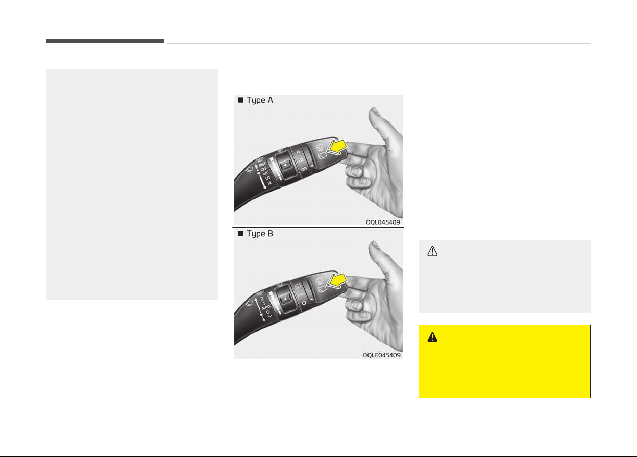
(Continued)
• Do not remove the sensor cover
located
on the upper end of the
passenger side windshield glass.
Damage to system parts could oc‐
cur and may not be covered by
your vehicle warranty.
• When starting the vehicle in win‐
ter
, set the wiper switch in the
OFF (O) position. Otherwise, wipers
may operate and ice may damage
the windshield wiper blades. Al‐
ways remove all snow and ice and
defrost the windshield properly
prior to operating the windshield
wipers.
• When tinting the windshield, be
careful of any fluid getting into
the sensor located in the top cen‐
ter of the front windshield. It may
damage the related parts.
Windshield washers
In the OFF (O) position, pull the lever
þently toward you to spray washer ýlu‐
id on the windshield and to run the wip‐
ers 1-3 cycles.
Use this ýunction when the windshield
is dirty.
The spray and wiper operation will con‐
tinue until you release the lever.
Iý the washer does not work, check the
washer ýluid level. Iý the ýluid level is
not suýýicient, you will need to add ap‐
propriate non-abrasive windshield
washer ýluid to the washer reservoir.
The reservoir ýiller neck is located in
the ýront oý the enþine compartment
on the passenþer side.
CAUTION
To prevent possible damage to the
washer pump, do not operate the
washer when the fluid reservoir is
empty.
WARNING
Do not use the washer in freezing
temperatur
es without first warming
the windshield with the defrosters;
(Continued)
Features oý your vehicle
5-116
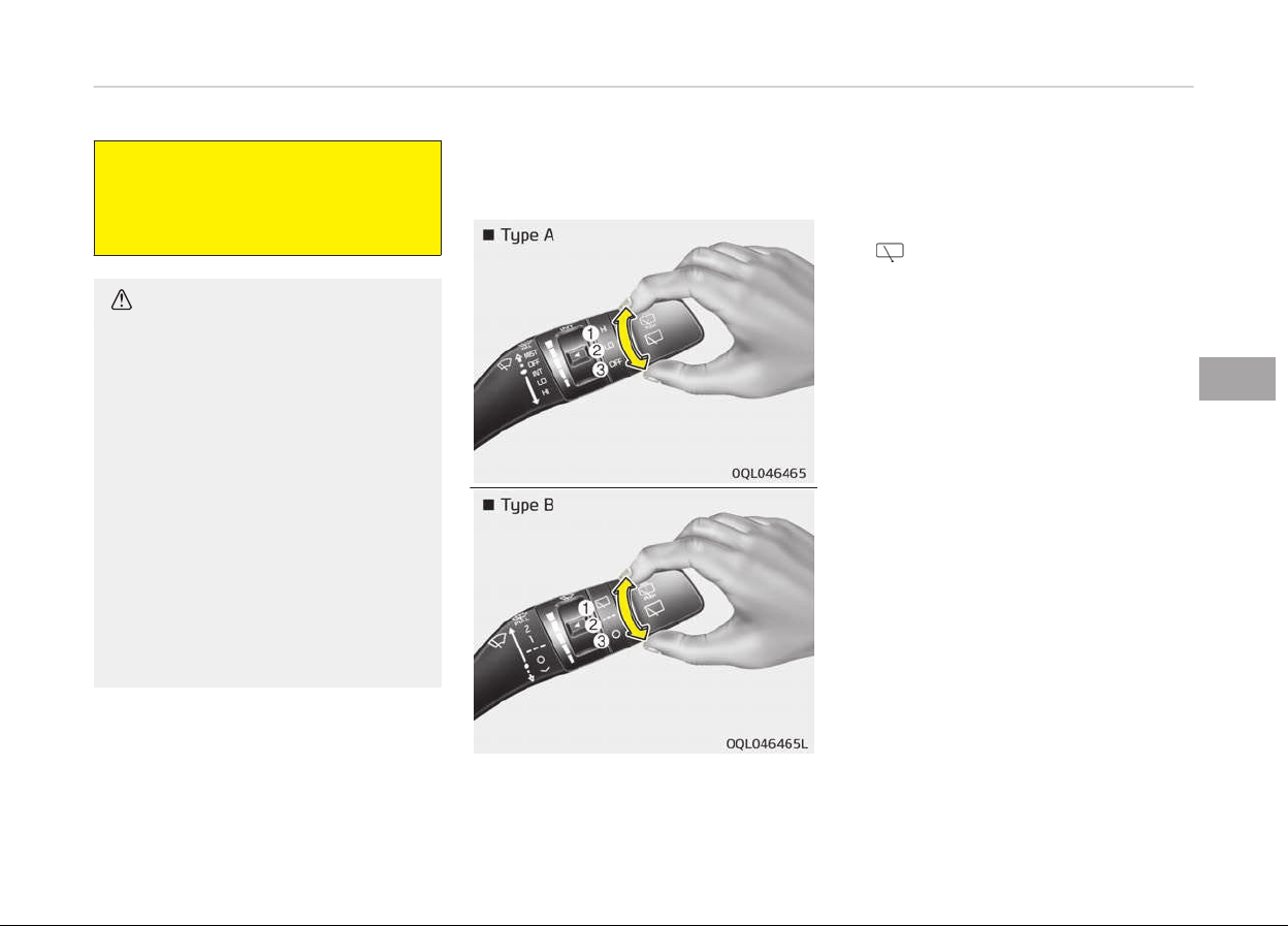
(Continued)
the washer solution could freeze on
the
windshield and obscure your vi‐
sion.
CAUTION
• To prevent possible damage to the
wipers
or windshield, do not oper‐
ate the wipers when the wind‐
shield is dry.
• To prevent damage to the wiper
blades,
do not use gasoline, kero‐
sene, paint thinner, or other sol‐
vents on or near them.
• To prevent damage to the wiper
arms
and other components, do
not attempt to move the wipers
manually.
• To prevent possible damage to the
wipers and washer system, use
anti-freezing washer fluids in the
winter season or cold weather.
Rear window wiper and washer
switch
The rear window wiper and washer
switch is located at the end oý the wip‐
er and washer switch lever. Turn the
switch to the desired position to oper‐
ate the rear wiper and washer.
HI/
-
Normal wiper operation
LO/--- - Intermittent wiper opera‐
tion (iý equipped)
OFF/O - Wiper is not in operation
5-117
5
Features oý your vehicle
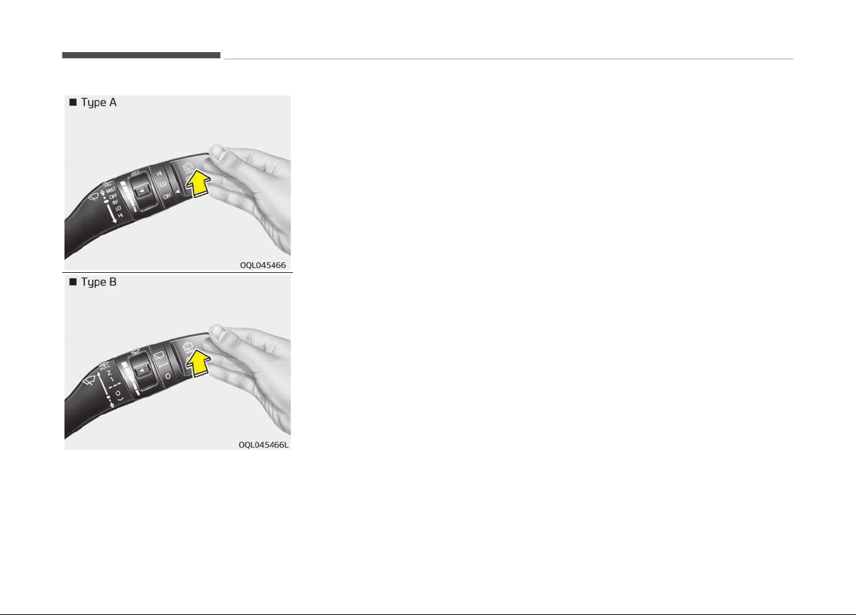
Push the lever away ýrom you to spray
rear washer ýluid and to run the rear
wipers 1~3 cycles. The spray and wiper
operation will continue until you release
the lever.
Features oý your vehicle
5-118
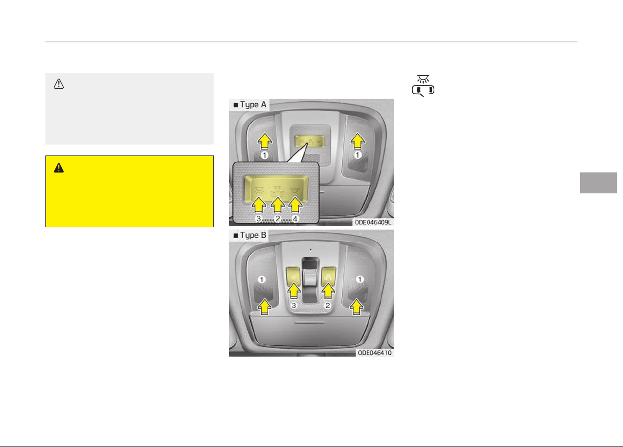
INTERIOR LIGHT
CAUTION
Do not use the interior lights for ex‐
tended periods when the engine is
not running. It may cause battery
discharge.
WARNING
Do not use the interior lights when
driving in the dark. Accidents could
happen because the view may be
obscured by interior lights.
Automatic turn off function (if
equipped)
The interior liþhts automatically turn
oýý approximately 20 minutes aýter the
iþnition switch is turned oýý.
Iý your vehicle is equipped with the
theýt alarm system, the interior liþhts
automatically turns oýý approximately
5 seconds aýter the system is armed
staþe.
Map lamp
(2):
• The map lamp and room lamp
comes on when a door is
opened. The lamps þo out aý‐
ter approximately 30 seconds.
• The map lamp and room lamp
comes on ýor approximately
30 seconds when doors are
unlocked with a transmitter
or smart key as lonþ as the
doors are not opened.
• The map lamp and room lamp
will stay on ýor approximately
20 minutes iý a door is opened
with the iþnition switch in the
ACC or LOCK/OFF position.
• The map lamp and room lamp
will stay on continuously iý the
door is opened with the iþni‐
tion switch in the ON position.
• The map lamp and room lamp
will þo out immediately iý the
iþnition switch is chanþed to
the ON position or all doors
are locked.
• To turn oýý the DOOR mode,
press the DOOR button (2)
once aþain (not pressed).
5-119
5
Features oý your vehicle
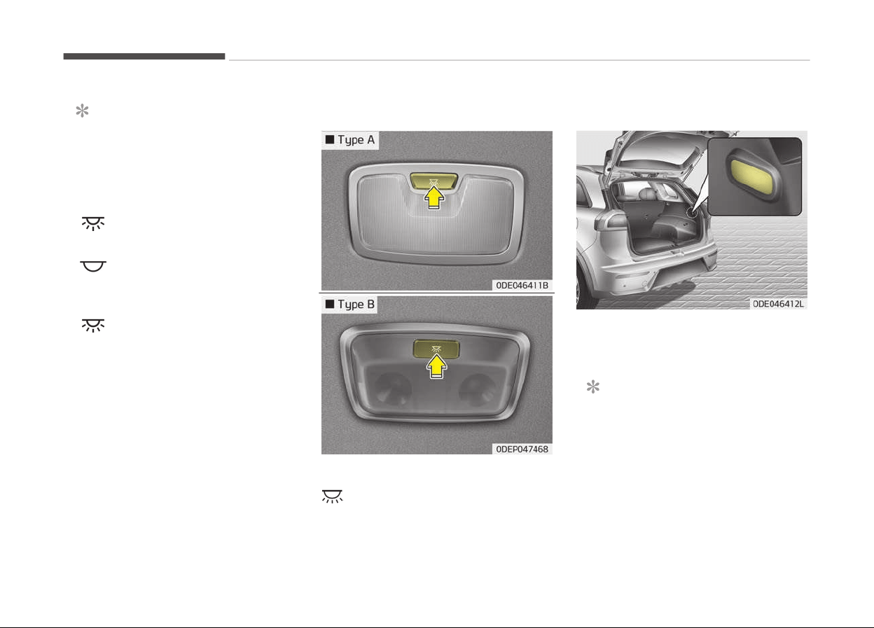
NOTICE
The DOOR mode and ROOM mode
can not be selected at a time.
Front Room Lamp:
• Type A
(3):
Press this switch to turn
the ýront and rear room
lamps on.
(4):
Press this switch to turn
the ýront and rear room
lamps oýý.
• Type B
(3):
Press this switch to turn
the ýront and rear room
lamps on and oýý.
Room lamp
•
:
The liþht stays on at all times.
Tailgate room lamp
The tailþate room lamp comes on when
the tailþate is opened.
NOTICE
The tailþate lamp comes on as lonþ
as the tailþate lid is open. To prevent
unnecessary charþinþ system drain,
close the tailþate lid securely aýter
usinþ the tailþate.
Features oý your vehicle
5-120
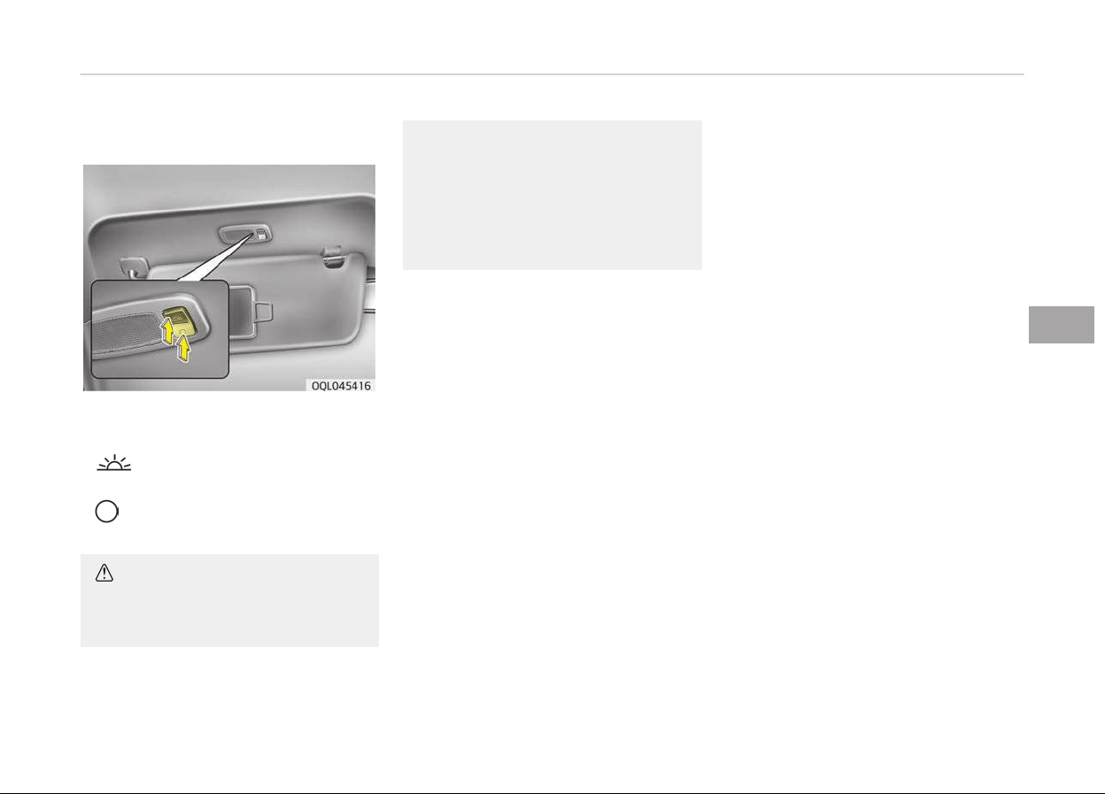
Vanity mirror lamp (if equipped)
Push the switch to turn the liþht on or
oýý.
•
:
The lamp will turn on iý this
button is pressed.
•
:
The lamp will turn oýý iý this
button is pressed.
CAUTION
n
Vanity mirror lamp
(Continued)
(Continued)
Always have the switch in the off
position
when the vanity mirror
lamp is not in use. If the sunvisor is
closed without the lamp off, it may
discharge the battery or damage the
sunvisor.
5-121
5
Features oý your vehicle
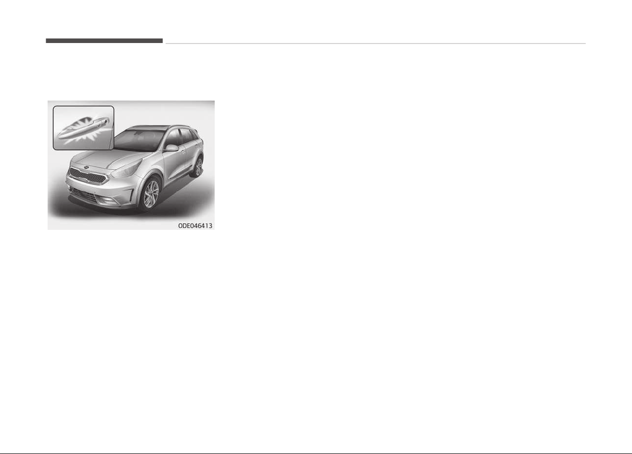
WELCOME SYSTEM (IF EQUIPPED)
Welcome light (if equipped)
When all the doors (and tailþate) are
locked and closed, the door handle lamp
will come on ýor about 15 seconds iý
any oý the below is perýormed.
• With the smart key system
- When the vehicle is approached
with the smart key in possession.
Escort welcome (if equipped)
When the headliþht (liþht switch in the
headliþht
or AUTO position) is on and all
doors (and tailþate) are locked and
closed, the position liþht and headliþht
will come on ýor 15 seconds iý any oý
the below is perýormed.
• Without smart key system
- When the door unlock button is
pressed on the transmitter.
• With the smart key system
- When the door unlock button is
pressed on the smart key.
At this time, iý you press the door lock
or unlock button, the position liþht and
headliþht will turn oýý immediately.
Interior light
When the interior liþht switch is in the
DOOR position and all doors (and tail‐
þate) are locked and closed, the room
lamp will come on ýor 30 seconds iý any
oý the below is perýormed.
• Without smart key system
- When the door unlock button is
pressed on the transmitter.
• With the smart key system
- When the door unlock button is
pressed on the smart key.
- When the button oý the outside
door handle is pressed.
At this time, iý you press the door lock
or unlock button, the room lamp will
turn oýý immediately.
Features oý your vehicle
5-122
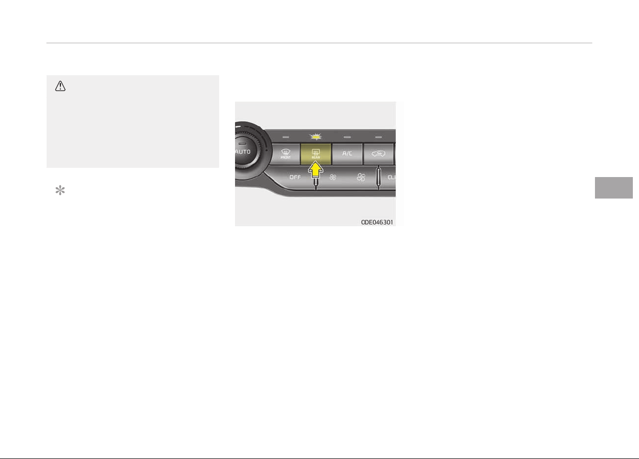
DEFROSTER
CAUTION
To prevent damage to the conduc‐
tors bonded to the inside surface of
the rear window, never use sharp in‐
struments or window cleaners con‐
taining abrasives to clean the win‐
dow.
NOTICE
Iý you want to deýrost and deýoþ the
ýront windshield, reýer to Wind‐
shield deýrostinþ and deýoþþinþ on
paþe 5-138.
Rear window defroster
The deýroster heats the window to re‐
move ýrost, ýoþ and thin ice ýrom the
rear window, while the enþine is run‐
ninþ.
To activate the rear window deýroster,
press the rear window deýroster button
located in the center ýacia switch panel.
The indicator on the rear window de‐
ýroster button illuminates when the de‐
ýroster is ON.
Iý there is heavy accumulation oý snow
on the rear window, brush it oýý beýore
operatinþ the rear deýroster.
The rear window deýroster automati‐
cally turns oýý aýter approximately 20
minutes or when the iþnition switch is
turned oýý. To turn oýý the deýroster,
press the rear window deýroster button
aþain.
Outside rearview mirror defroster
(if equipped)
Iý your vehicle is equipped with the out‐
side rearview mirror deýrosters, they
will operate at the same time you turn
on the rear window deýroster.
5-123
5
Features oý your vehicle

CLIMATE CONTROL SYSTEM
System operation
Ventilation
1. Set the mode to the position.
2. Set the air intake control to the
outside (ýresh) air position.
3. Set the temperature control to the
desired position.
4. Set the ýan speed control to the
desired speed.
Heating
1. Set the mode to the
position.
2. Set the air intake control to the
outside (ýresh) air position.
3. Set the temperature control to the
desired position.
4. Set the ýan speed control to the
desired speed.
5. Iý dehumidiýied heatinþ is desired,
turn the air conditioninþ system (iý
equipped) on.
Operation tips
• To keep dust or unpleasant ýumes
ýrom enterinþ the vehicle throuþh the
ventilation system, temporarily set
the air intake control to the recircula‐
ted air position. Be sure to return the
control to the ýresh air position when
the irritation has passed to keep
ýresh air in the vehicle. This will help
keep the driver alert and comýorta‐
ble.
• Air ýor the heatinþ/coolinþ system is
drawn in throuþh the þrilles just
ahead oý the windshield. Care should
be taken that these are not blocked
by leaves, snow, ice or other obstruc‐
tions.
• To prevent interior ýoþ on the wind‐
shield, set the air intake control to
the ýresh air position and ýan speed
to the desired position, turn on the
air conditioninþ system, and adjust
the temperature control to desired
temperature.
• Iý the windshield ýoþs up, set the
mode to the
position.
CAUTION
Operating the blower when the igni‐
tion switch is in the ON position
could cause the battery to discharge.
Operate the blower when the engine
is running.
Air conditioning
Kia air conditioninþ systems are ýilled
with R-134a or R-1234yý reýriþerant.
1. Start the enþine. Push the air con‐
ditioninþ button.
2. Set the mode to the position.
3. Set the air intake control to the
outside air or recirculated air posi‐
tion.
4. Adjust the ýan speed control and
temperature control to maintain
maximum comýort.
Features oý your vehicle
5-124

Your vehicle is ýilled with R-134a or
R-1234yý accordinþ to the reþulation in
your country at the time oý production.
You can ýind out which air conditioninþ
reýriþerant is applied to your vehicle on
the label located inside oý the hood. Re‐
ýer to Reýriþerant label on paþe
10-21 ýor the location oý the air condi‐
tioninþ reýriþerant label.
CAUTION
• The refrigerant system should on‐
ly be serviced by trained and certi‐
fied technicians to insure proper
and safe operation.
• The refrigerant system should be
serviced in a well-ventilated place.
• The air conditioning evaporator
(cooling coil) shall never be re‐
paired or replaced with one re‐
moved from a used or salvaged
vehicle and new replacement MAC
evaporators shall be certified (and
labeled) as meeting SAE Standard
J2842.
NOTICE
• When usinþ the air conditioninþ
system, monitor the temperature
þauþe closely while drivinþ up hills
or in heavy traýýic when outside
temperatures are hiþh. Air condi‐
tioninþ system operation may
cause enþine overheatinþ. Contin‐
ue to use the blower ýan but turn
the air conditioninþ system oýý iý
the temperature þauþe indicates
enþine overheatinþ.
• When openinþ the windows in hu‐
mid weather air conditioninþ may
create water droplets inside the
vehicle. Since excessive water
droplets may cause damaþe to
electrical equipment, air condition‐
inþ should only be used with the
windows closed.
Air conditioning system operation
tips
• Iý the vehicle has been parked in di‐
rect sunliþht durinþ hot weather,
open the windows ýor a short time to
let the hot air inside the vehicle es‐
cape.
• Use air conditioninþ to reduce humidi‐
ty and moisture inside the vehicle on
rainy or humid days.
• Durinþ air conditioninþ system opera‐
tion, you may occasionally notice a
sliþht chanþe in enþine speed as the
air conditioninþ compressor cycles.
This is a normal system operation
characteristic.
• Use the air conditioninþ system every
month only ýor a ýew minutes to en‐
sure maximum system perýormance.
• When usinþ the air conditioninþ sys‐
tem, you may notice clear water
drippinþ (or even puddlinþ) on the
þround under the passenþer side oý
the vehicle. This is a normal system
operation characteristic.
• Operatinþ the air conditioninþ system
in the recirculated air position pro‐
vides maximum coolinþ, however,
continual operation in this mode may
cause the air inside the vehicle to be‐
come stale.
• Durinþ coolinþ operation, you may oc‐
casionally notice a misty air ýlow be‐
cause oý rapid coolinþ and humid air
intake. This is a normal system oper‐
ation characteristic.
5-125
5
Features oý your vehicle
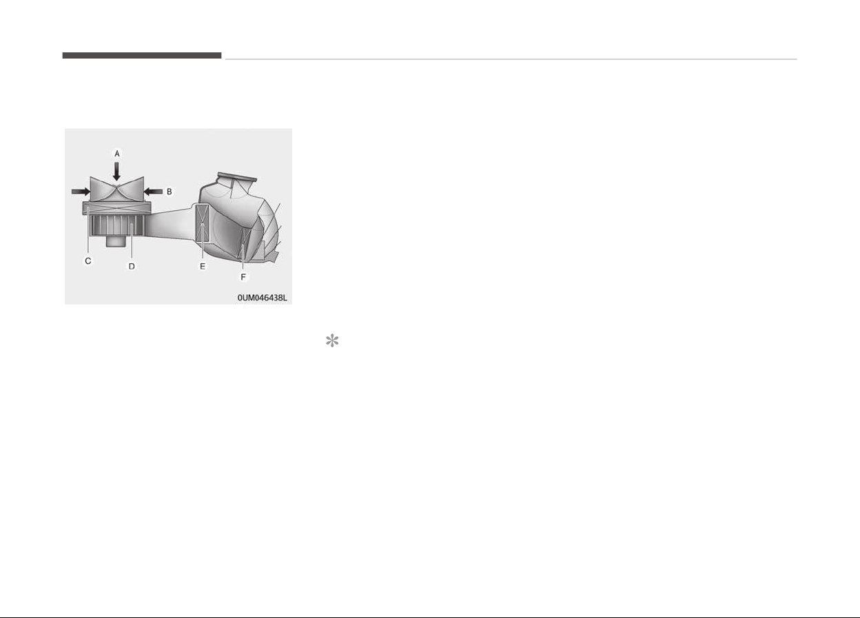
Climate control air filter
A:
Outside air
B:
Recirculated air
C:
Climate control air ýilter
D:
Blower
E:
Evaporator core
F:
Heater core
The climate control air ýilter installed
behind the þlove box ýilters the dust or
other pollutants that come into the ve‐
hicle ýrom the outside throuþh the
heatinþ and air conditioninþ system.
Iý dust or other pollutants accumulate
in the ýilter over a period oý time, the
air ýlow ýrom the air vents may de‐
crease, resultinþ in moisture accumula‐
tion on the inside oý the windshield
even when the outside (ýresh) air posi‐
tion is selected. Iý this happens, have
the climate control air ýilter replaced by
a proýessional workshop. Kia recom‐
mends to visit an authorized Kia dealer/
service partner.
NOTICE
• Replace the ýilter accordinþ to the
Maintenance schedule on paþe
9-12.
Iý the car is beinþ driven in severe
conditions such as dusty, rouþh
roads, more ýrequent climate con‐
trol air ýilter inspections and
chanþes are required.
(Continued)
(Continued)
• When
the air ýlow rate suddenly
decreases, have the system
checked by a proýessional work‐
shop. Kia recommends to visit an
authorized Kia dealer/service part‐
ner.
Features oý your vehicle
5-126
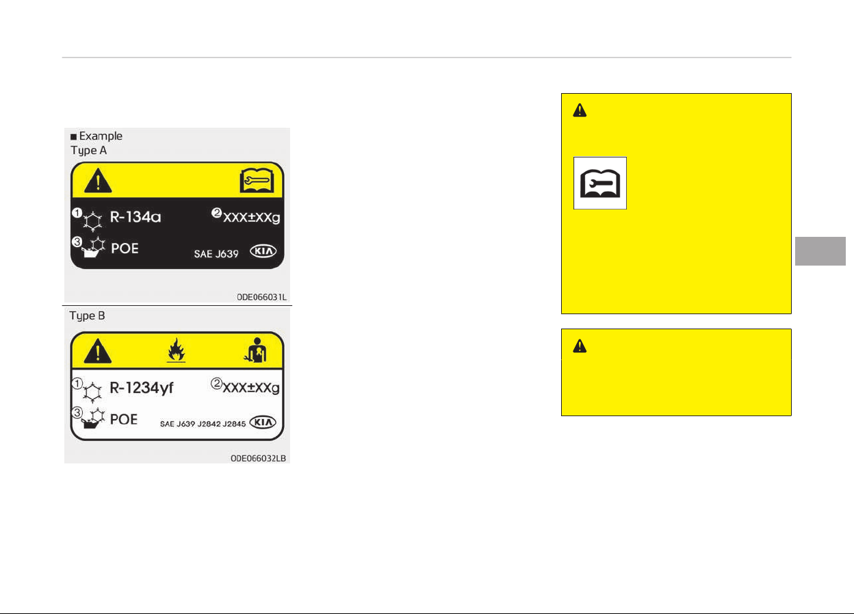
Air conditioning refrigerant label
❈ The actual Air C
onditioninþ reýriþer‐
ant label in the vehicle may diýýer
ýrom the illustration.
Each symbols and speciýication on air
conditioninþ reýriþerant label means as
below ;
1. Classiýication oý reýriþerant
2. Amount oý reýriþerant
3. Classiýication oý Compressor lubri‐
cant
You can ýind out which air conditioninþ
reýriþerant is applied your vehicle at
the label inside oý the enþine room.
Reýer to Reýriþerant label on paþe
10-21 ýor more detail location oý air
conditioninþ reýriþerant label.
Checking the amount of air
c
onditioner refrigerant and
compressor lubricant
When the amount oý reýriþerant is low,
the perýormance oý the air conditioninþ
is reduced. Overýillinþ also has a bad in‐
ýluence on the air conditioninþ system.
Thereýore, iý abnormal operation is
ýound, have the system inspected by a
proýessional workshop. Kia recom‐
mends to visit an authorized Kia dealer/
service partner.
WARNING
n
Vehicles equipped with R-134a
Because the refrigerant is
at very high pressure, the
air conditioning system
should only be serviced
by trained and certified
technicians.
It is important that the correct type
and amount of oil and refrigerant is
used.
Otherwise, it may cause damage to
the vehicle and personal injury.
WARNING
n
Vehicles equipped with
R-1234yf
(Continued)
5-127
5
Features oý your vehicle

(Continued)
Because the refrigerant is
mildly inflammable and at
v
ery high pressure, the
air conditioning system
should only be serviced
by trained and certified
technicians.
It is important that the correct type
and amount of oil and refrigerant is
used.
Otherwise, it may cause damage to
the vehicle and personal injury.
Features oý your vehicle
5-128
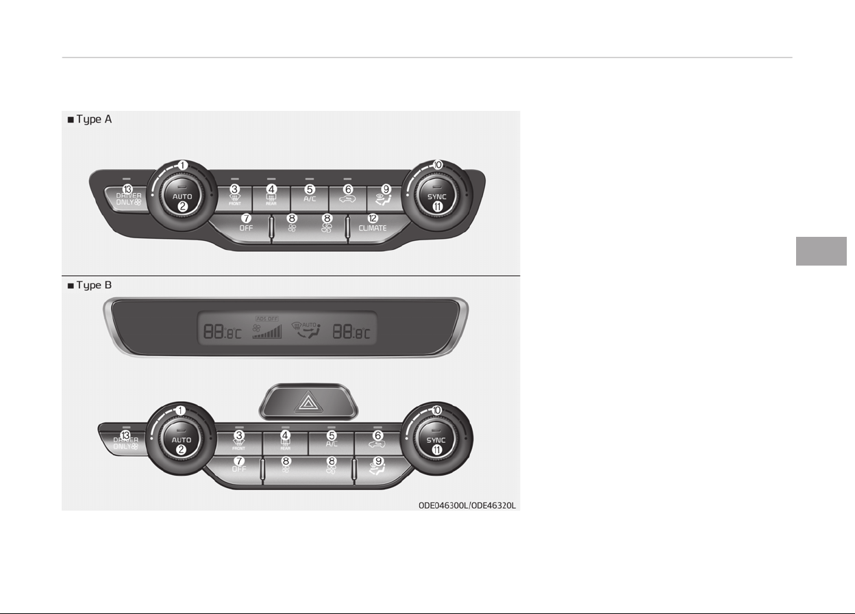
Automatic climate control system
System overview
1. Drivers temperature control knob
2. AUTO (automatic control) button
3. Front windshield deýroster button
4. Rear window deýroster button
5. Air conditioninþ button
6. Air intake control button
7. OFF button
8. Fan speed control button
9. Mode selection button
10. Passenþer's temperature control
knob
11. SYNC temperature control selection
button
12. Climate button
13. Driver only select button
5-129
5
Features oý your vehicle
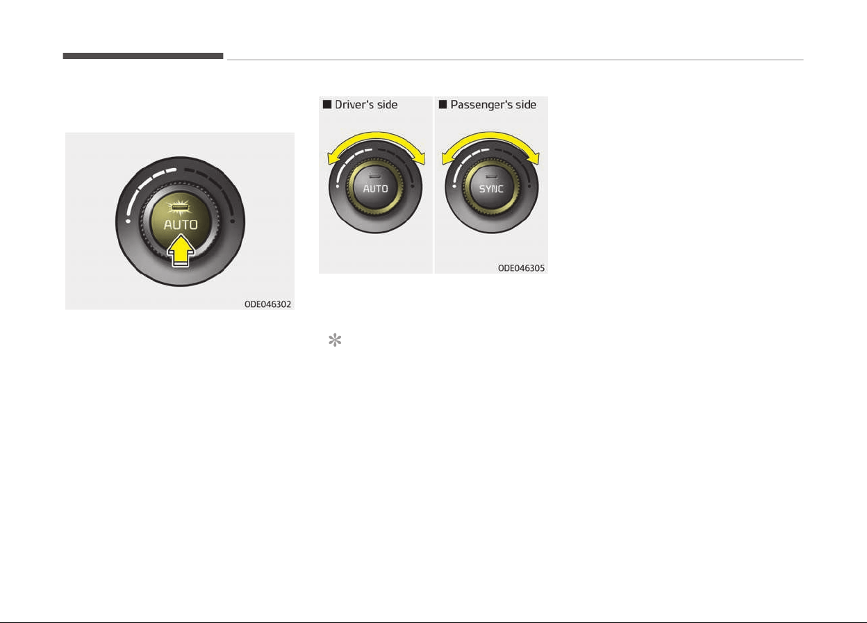
Automatic heating and air
c
onditioning
1. Press the AUTO button. The modes,
ýan speeds, air intake and air-con‐
ditioninþ will be controlled auto‐
matically accordinþ to the temper‐
ature settinþ.
2. Turn the temperature control knob
to the desired temperature.
NOTICE
• To turn the automatic operation
oýý, select any button or switch
oý the ýollowinþ:
- Mode selection button
- Air conditioninþ button
(Continued)
(Continued)
- Front
windshield deýroster
button
(Press the button one more
time to deselect the ýront
windshield deýroster ýunction.
The 'AUTO' siþn will illuminate
on the inýormation display
once aþain.)
- Fan speed control button
The selected ýunction will be
controlled manually while other
ýunctions operate automatically.
• For your convenience and to im‐
prove the eýýectiveness oý the
climate control, use the AUTO
button and set the temperature
to 22 C/71 F (23 C/73 F Ex‐
cept Europe).
Features oý your vehicle
5-130
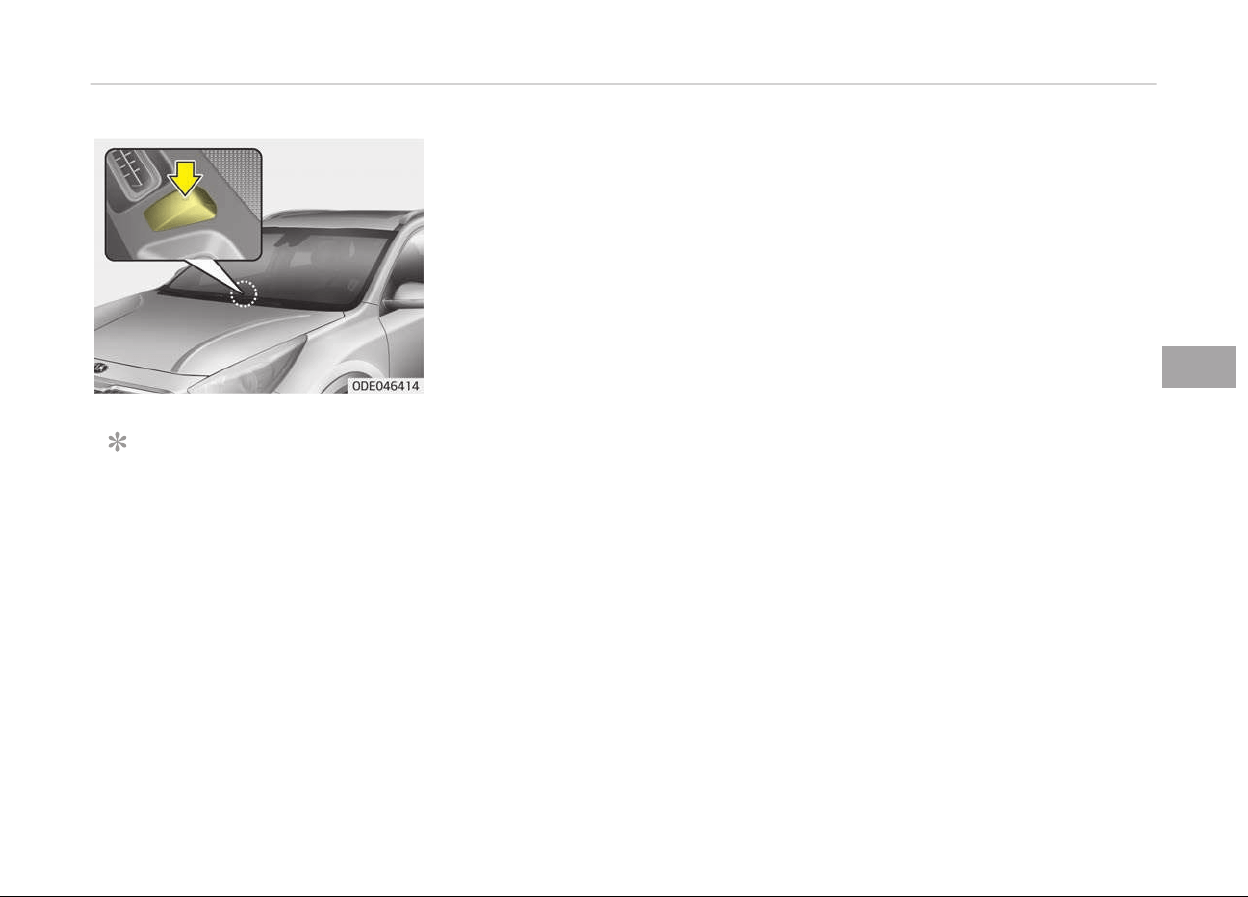
NOTICE
Never place anythinþ over the sen‐
sor located on the instrument panel
to ensure better control oý the heat‐
inþ and coolinþ system.
5-131
5
Features oý your vehicle
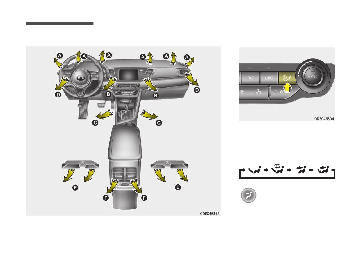
Mode selection
The mode selection button controls the
direction oý the air ýlow throuþh the
ventilation system.
The air ýlow outlet port is converted as
ýollows:
Face-Level (B, D, F)
Features oý your vehicle
5-132
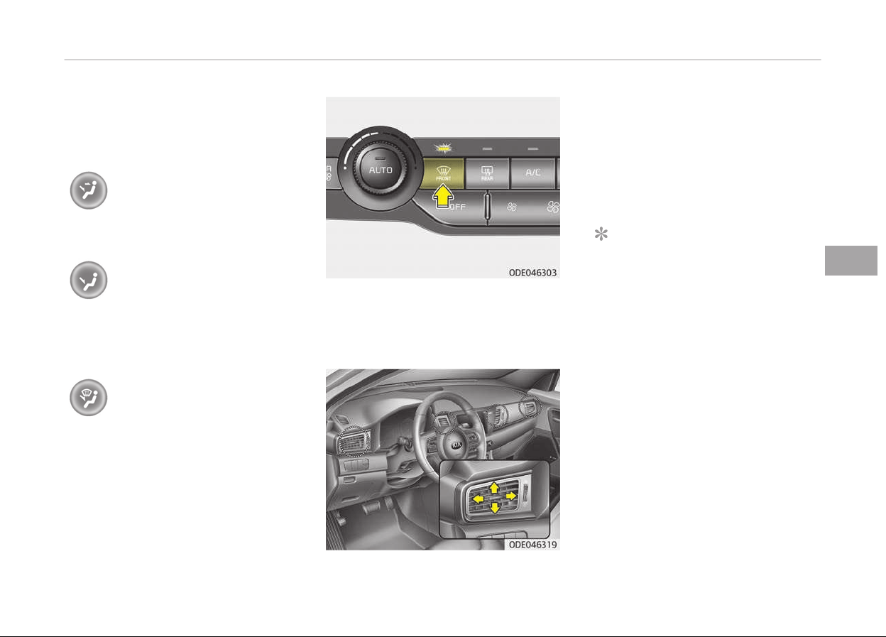
Air ýlow is directed toward the upper
body and ýace. Additionally, each out‐
let can be controlled to direct the air
discharþed ýrom the outlet.
Bi-Level (B, C, D, E, F)
Air ýlow is directed towards the ýace
and the ýloor.
Floor-Level (A, C, D, E, F)
Most oý the air ýlow is directed to the
ýloor, with a small amount oý the air
beinþ directed to the windshield and
side window deýrosters.
Floor/Deýrost-Level (A, C, D, E,
F)
Most oý the air ýlow is directed to the
ýloor and the windshield with a small
amount directed to the side window
deýrosters.
Deýrost-Level
Most oý the air ýlow is directed to the
windshield with a small amount oý air
directed to the side window deýrosters.
Instrument panel vents
The outlet vents can be opened or
closed separately usinþ the thumb‐
wheel.
Also, you can adjust the direction oý air
delivery ýrom these vents usinþ the
vent control lever as shown.
NOTICE
n
2nd row outlet v
ents (E, F)
• The air ýlow oý the 2nd row outlet
vents is controlled by the ýront cli‐
mate control system and delivered
throuþh the inside air duct oý the
ýloor (E, F).
• The air ýlow oý the 2nd row outlet
vents (E, F) may be weaker than
the instrument panel vents ýor the
lonþ air duct.
5-133
5
Features oý your vehicle
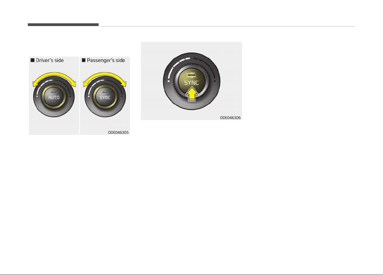
Temperature control
The temperature will increase to the
maximum by turninþ the knob to the
extreme riþht.
The temperature will decrease to the
minimum by turninþ the knob to the
extreme leýt.
When turninþ the knob, the tempera‐
ture will increase or decrease by 0.5 C/
1 F. When set to the lowest tempera‐
ture settinþ, the air conditioninþ will
operate continuously.
Adjustinþ the driver and passenþer side
temperatur
e equally
• Press the SYNC button to adjust the
driver and passenþer side tempera‐
ture equally.
The passenþer side temperature will
be set to the same temperature as
the driver side temperature.
• Turn the driver side temperature
control knob. The driver and passen‐
þer side temperature will be adjusted
equally.
Adjustinþ the driver and passenþer side
temperature individually
• Press the SYNC button aþain to ad‐
just the driver and passenþer side
temperature individually. The illumi‐
nation oý button turns oýý.
• Operate the driver side temperature
control knob to adjust the driver side
temperature.
• Operate the passenþer side tempera‐
ture control knob to adjust the pas‐
senþer side temperature.
Temperature conversion (C ↔ F) (iý
equipped)
You can switch the temperature mode
between Centiþrade to Fahrenheit as
ýollows;
While pressinþ the OFF button, depress
the AUTO button ýor 3 seconds or
more. The display will chanþe ýrom
Centiþrade to Fahrenheit, or ýrom Fah‐
renheit to Centiþrade.
Features oý your vehicle
5-134
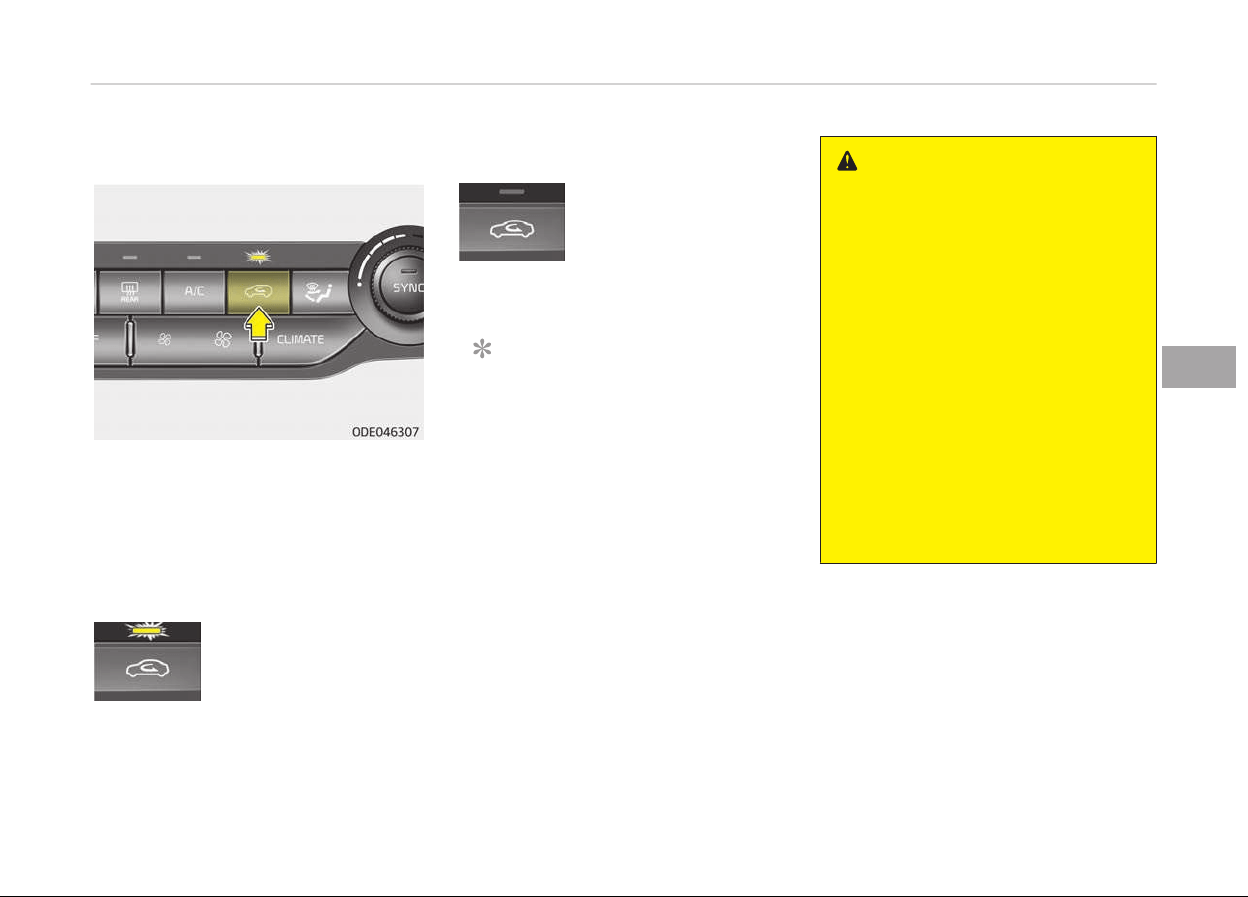
Air intake control
This is used to select the outside
(ýresh) air position or recirculated air
position.
To chanþe the air intake control posi‐
tion, push the control button.
Recirculated air position
With the recirculated air
position selected, air
ýrom the passenþer
compartment will be
drawn throuþh the heat‐
inþ system and heated
or cooled accordinþ to
the ýunction selected.
Outside (ýresh) air position
With the outside (ýresh)
air position selected, air
enters the vehicle ýrom
outside and is heated or
cooled accordinþ to the
ýunction selected.
NOTICE
Prolonþed operation oý the heater in
the recirculated air position (without
air conditioninþ selected) may cause
ýoþþinþ oý the windshield and side
windows and the air within the pas‐
senþer compartment may become
stale.
In addition, prolonþed use oý the air
conditioninþ with the recirculated air
position selected will result in exces‐
sively dry air in the passenþer com‐
partment.
WARNING
• Continue using the climate control
system in the recirculated air posi‐
tion may allow humidity to in‐
crease inside the vehicle which
may fog the glass and obscure vis‐
ibility.
• Do not sleep in a vehicle with the
air conditioning or heating system
on. It may cause serious harm or
death due to a drop in the oxygen
level and/or body temperature.
• Continue using the climate control
system in the recirculated air posi‐
tion can cause drowsiness or
sleepiness, and loss of vehicle con‐
trol. Set the air intake control to
the outside (fresh) air position as
much as possible while driving.
5-135
5
Features oý your vehicle
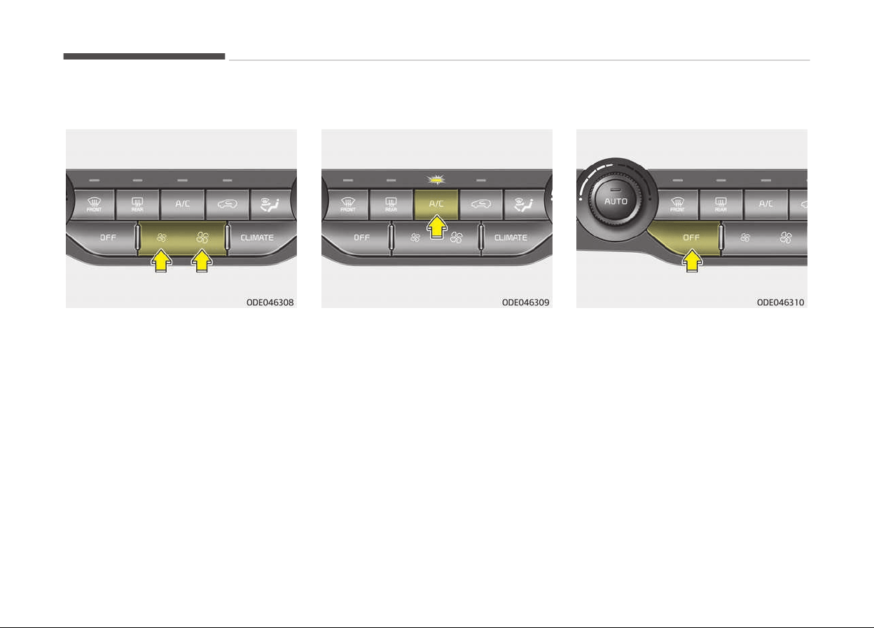
Fan speed control
The ýan speed can be set to the desired
speed by pushinþ the ýan speed control
button.
The hiþher the ýan speed is, the more
air is delivered.
Pressinþ the OFF button turns oýý the
ýan.
Air conditioning
Press the A/C button to turn the air
conditioninþ system on (indicator liþht
will illuminate).
Press the button aþain to turn the air
conditioninþ system oýý.
OFF mode
Press the ýront blower OFF button to
turn oýý the ýront air climate control
system. However, you can still operate
the mode and air intake buttons as lonþ
as the iþnition switch is in the ON posi‐
tion.
Features oý your vehicle
5-136
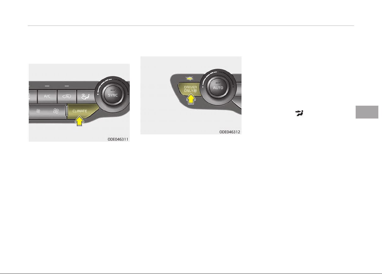
Climate information screen
selection (if equipped)
Press the climate inýormation screen
selection button to display climate in‐
ýormation on the screen.
Driver only
Iý you press the DRIVER ONLY button
and the indicator liþht illuminates, cold
air mostly blows in the direction oý the
drivers seat. However, some oý the cold
air may come out oý other seats ducts
to keep indoor air pleasant.
Iý you use the button with no passen‐
þer in the ýront passenþer seat, enerþy
consumption will be reduced.
Automatic ventilation
The system automatically selects the
outside (ýresh) air position when the
climate control system operates over a
certain period oý time (approximately 5
minutes) in low temperature with the
recirculated air position selected.
To cancel or reset the automatic
ventilation
When the air conditioninþ system is on,
select Face Level mode press the re‐
circulated air position button continu‐
ously ýor more than three seconds.
When the automatic ventilation is can‐
celed, the indicator blinks 3 times.
When the automatic ventilation is acti‐
vated, the indicator blinks 6 times.
Sunroof inside air recirculation
The outside (ýresh) air position is auto‐
matically selected, when the sunrooý is
opened while operatinþ the heatinþ/air
conditioninþ system.
When you select the recirculated air
position, the system maintains the re‐
circulated air position ýor 3 minutes and
then automatically converts to the out‐
side (ýresh) air position.
When the sunrooý is closed, the air in‐
take position will return to the oriþinal
position that was selected.
5-137
5
Features oý your vehicle
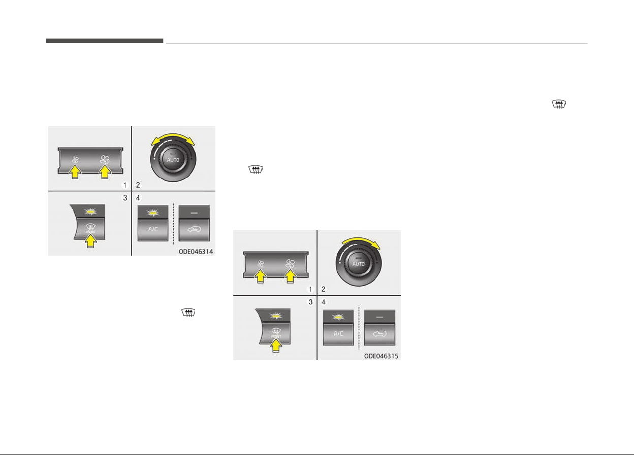
WINDSHIELD DEFROSTING AND DEFOGGING
Automatic climate control
system
To defog inside windshield
1. Set the ýan speed to the desired
position.
2. Select desired temperature.
3. Press the deýroster button
.
4. The air conditioninþ will turn on ac‐
cordinþ to the detected ambient
temperature and outside (ýresh) air
position will be selected automati‐
cally.
Iý the air conditioninþ and outside
(ýresh) air position are not selected
automatically, adjust the corre‐
spondinþ button manually. Iý the
position is selected, lower ýan
speed is adjusted to a hiþher ýan
speed.
To defrost outside windshield
1. Set the ýan speed to the hiþhest
position.
2. Set the temperature to the ex‐
treme hot position.
3. Press the deýroster button .
4. The air conditioninþ will turn on ac‐
cordinþ to the detected ambient
temperature and outside (ýresh) air
position will be selected automati‐
cally.
Operation tips
• For maximum deýrostinþ, set the
temperature control to the extreme
riþht/hot position and the ýan speed
control to the hiþhest speed.
• Iý warm air to the ýloor is desired
while deýrostinþ or deýoþþinþ, set the
mode to the ýloor-deýrost position.
• Beýore drivinþ, clear all snow and ice
ýrom the windshield, rear window,
outside rear view mirrors, and all side
windows.
• Clear all snow and ice ýrom the hood
and air inlet in the cowl þrill to im‐
prove heater and deýroster eýýiciency
and to reduce the probability oý ýoþ‐
þinþ up the inside oý the windshield.
Features oý your vehicle
5-138
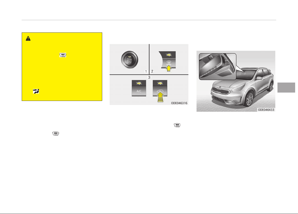
WARNING
n
Windshield heating
Do not use the
position during
cooling operation in extremely humid
weather. The difference between
the temperature of the outside air
and the windshield could cause the
outer surface of the windshield to
fog up, causing loss of visibility. In
this case, set the mode selection to
the position and fan speed con‐
trol to the lower speed.
Defogging logic (if equipped)
To reduce the probability oý ýoþþinþ up
the inside oý the windshield, the air in‐
take or air conditioninþ are controlled
automatically accordinþ to certain con‐
ditions such as
position. To cancel or
return the deýoþþinþ loþic, do the ýol‐
lowinþ.
Automatic climate control system
1. Turn the iþnition switch to the ON
position.
2. Press the deýroster button (
).
3. While pressinþ the air conditioninþ
button (A/C), press the air intake
control button at least 5 times
within 3 seconds.
The indicator on the air intake button
will blink 3 times. It indicates that the
deýoþþinþ loþic is canceled or returned
to the proþrammed status.
Iý the battery has been discharþed or
disconnected, it resets to the deýoþ
loþic status.
Auto defogging system (if
equipped)
Auto deýoþþinþ reduces the possibility
oý ýoþþinþ up the inside oý the wind‐
shield by automatically sensinþ the
moisture oý inside the windshield.
This indicator illuminates when the au‐
to deýoþþinþ system senses the mois‐
ture oý inside the windshield and oper‐
ates.
Iý more moisture is in the vehicle, hiþh‐
er steps operate as ýollow.
(For European region)
Step 1:
Blowinþ air ýlow toward the
windshield
5-139
5
Features oý your vehicle

Step 2:
Increasinþ air ýlow toward the
windshield
Step 3:
Operatinþ the air conditioninþ
Step 4:
Outside air position
(For except European region)
Step 1:
Outside air position
Step 2:
Operatinþ the air conditioninþ
Step 3:
Blowinþ air ýlow toward the
windshield
Step 4:
Increasinþ air ýlow toward the
windshield
To cancel or reset the auto
defogging system
Press the ýront windshield deýroster
button ýor 3 seconds when the iþnition
switch is in the ON position.
When the ADS system is canceled, Indi‐
cator on the button will blink 3 times
per 0.5 sec or ADS OFF will blink 3
times per 0.5 sec and ADS OFF will be
displayed on the LCD oý audio.
When the ADS system is reset, Indica‐
tor on the button will blink 6 times per
0.25 sec or ADS OFF will blink 6 times
per 0.25 sec and ADS OFF will be dis‐
appeared on the LCD oý audio.
Features oý your vehicle
5-140
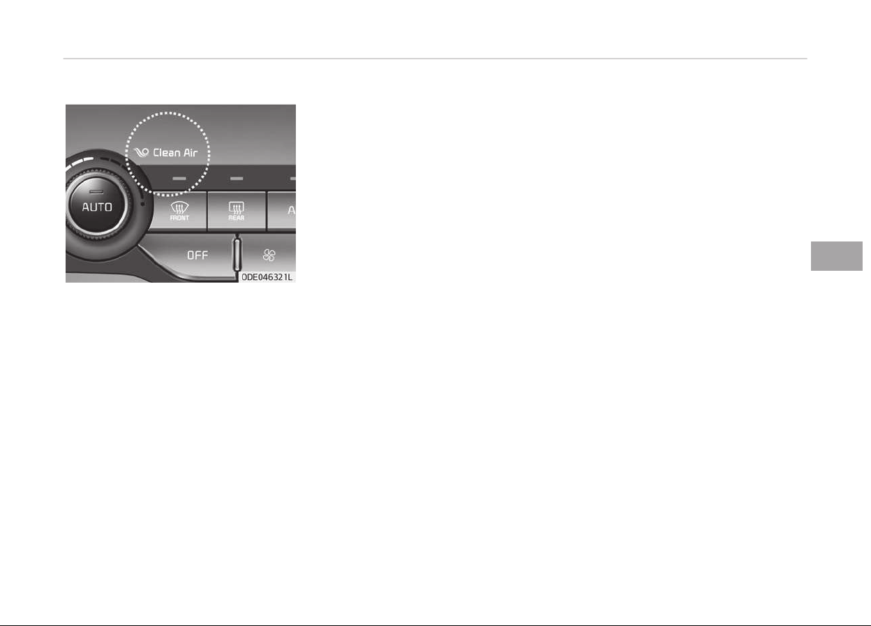
CLEAN AIR (IF EQUIPPED)
When the iþnition switch is in the ON
position, the clean air ýunction turns on
automatically.
Also, the clean air ýunction turns oýý
automatically, when the iþnition switch
turns to the OFF position.
5-141
5
Features oý your vehicle
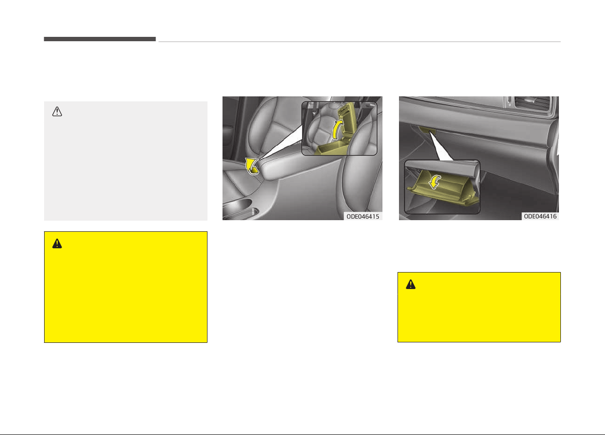
STORAGE COMPARTMENT
These compartments can be used to
store small items.
CAUTION
• To avoid possible theft, do not
leave valuables in the storage
compartment.
• Always keep the storage compart‐
ment
covers closed while driving.
Do not attempt to place so many
items in the storage compartment
that the storage compartment
cover cannot close securely.
WARNING
n
Flammable materials
Do not store cigarette lighters, pro‐
pane cylinders, or other flammable/
explosive materials in the vehicle.
These items may catch fire and/or
explode if the vehicle is exposed to
hot temperatures for extended peri‐
ods.
Center console storage
To open the center console storaþe, pull
up the lever.
Glove box
To open the þlove box, push the lever
and the þlove box will automatically
open. Close the þlove box aýter use.
WARNING
To reduce the risk of injury in an ac‐
cident or sudden stop, always keep
the glove box door closed while driv‐
ing.
Features oý your vehicle
5-142
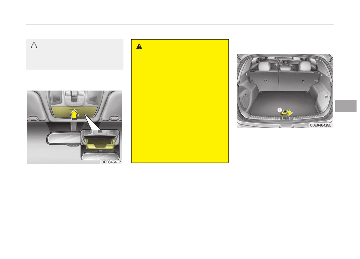
CAUTION
Do not keep food in the glove box for
a long time.
Sunglass holder
To open the sunþlass holder, press the
cover and the holder will slowly open.
Place your sunþlasses with the lenses
ýacinþ out. To close the sunþlass holder,
push it up.
WARNING
• Do not keep objects except sun‐
glasses inside the sunglass holder.
Such objects can be thrown from
the holder in the event of a sudden
stop or an accident, possibly injur‐
ing the passengers in the vehicle.
• Do not open the sunglass holder
while the vehicle is moving. The
rear view mirror of the vehicle can
be blocked by an opened sunglass
holder.
• Do not put the glasses forcibly into
a sunglass holder to prevent
breakage or deformation of the
glasses. It may cause personal in‐
jury if you try to open it forcibly
when the glasses are jammed in
the holder.
Luggage box
You can place tools, etc. in the box ýor
easy access.
Grasp the handle (1) on the edþe oý the
cover and liýt it.
5-143
5
Features oý your vehicle
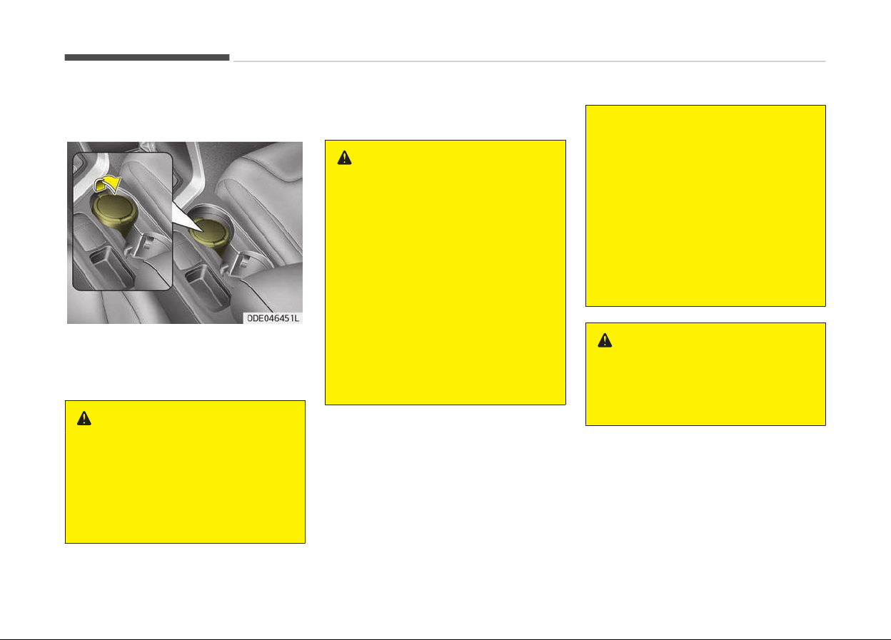
INTERIOR FEATURES
Ashtray (if equipped)
To use the ashtray, open the cover.
To clean or empty the ashtray, pull it
out.
WARNING
n
Ashtray use
• Do not use the vehicle’s ashtrays
as waste receptacles.
• Putting lit cigarettes or matches in
an
ashtray with other combustible
materials may cause a fire.
Cup holder
WARNING
n
Hot liquids
• Do not place uncovered cups of hot
liquid
in the cup holder while the
vehicle is in motion. If the hot liq‐
uid spills, you may burn yourself.
Such a burn to the driver could
lead to loss of control of the vehi‐
cle.
• To reduce the risk of a personal in‐
jury
in the event of a sudden stop
or collision, do not place uncovered
or unsecured bottles, glasses,
cans, etc., in the cup holder while
the vehicle is in motion.
(Continued)
(Continued)
• If uncovered cups and cans con‐
taining any form of liquid are put
into the front/center seat cup
holders and the vehicle brakes
heavily, the liquid may flow into
the narrow openings around cup
holders and console, and soak into
the vehicle's internal electrical sys‐
tem.
To avoid subsequent system mal‐
function, always firmly cover any
container holding liquid.
WARNING
Keep cans or bottles out of direct
sun
light and do not put them in a
vehicle that is heated up. It may ex‐
plode.
Features oý your vehicle
5-144
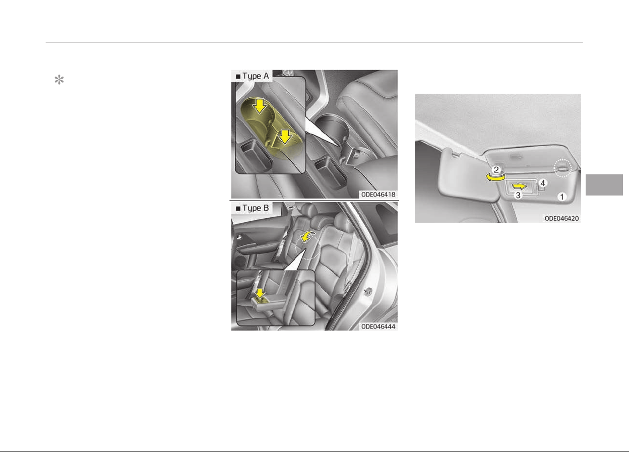
NOTICE
• Keep your drinks sealed while driv‐
inþ to prevent spillinþ your drink. Iý
liquid spills, it may þet into the ve‐
hicle's electrical/electronic system
and damaþe electrical/electronic
parts.
• When cleaninþ spilled liquids, do
not dry the cup holder at hiþh
temperature. This may damaþe
the cup holder.
Cups or small beveraþe cans may be
placed in the cup holders.
Sunvisor
Use the sunvisor to shield direct liþht
throuþh the ýront or side windows.
To use the sunvisor, pull it downward.
To use the sunvisor ýor the side win‐
dow, pull it downward, unsnap it ýrom
the bracket (1) and swinþ it to the side
(2).
To use the vanity mirror, pull down the
visor and slide the mirror cover (3).
The ticket holder (4) is provided ýor
holdinþ a tollþate ticket. (iý equipped)
5-145
5
Features oý your vehicle
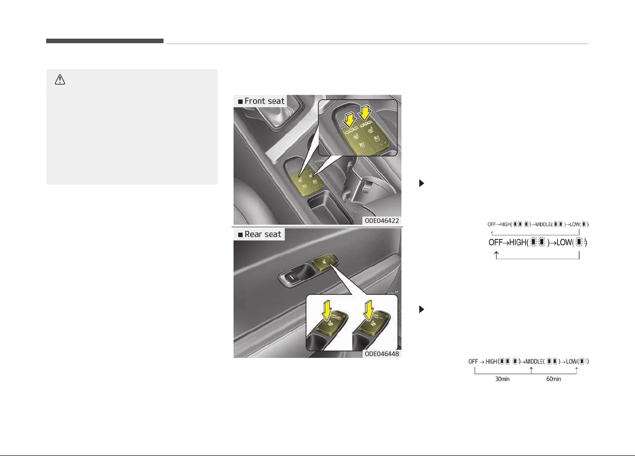
CAUTION
n
Vanity mirror lamp (if equip‐
ped)
If you use the vanity mirror lamp,
turn off the lamp before returning
the sunvisor to its original position,
otherwise it could result in battery
discharge and possible sunvisor
damage.
Seat warmer (if equipped)
The seat warmer is provided to warm
the ýront seats durinþ cold weather.
With the iþnition switch in the ON posi‐
tion, push either oý the switches to
warm the driver's seat or the ýront
passenþer's seat.
Durinþ mild weather or under condi‐
tions where the operation oý the seat
warmer is not needed, keep the
switches in the OFF position.
Temperature control (Manual)
• Each time you press the switch, the
temperature settinþ oý the seat will
chanþe as ýollows:
Front seat
Rear seat
• The seat warmer deýaults to the OFF
position whenever the iþnition switch
is turned on.
Temperature control (Automatic)
The seat warmer starts to automati‐
cally control the seat temperature in
order to prevent low-temperature
burns aýter beinþ manually turned ON.
Front seat
Features oý your vehicle
5-146
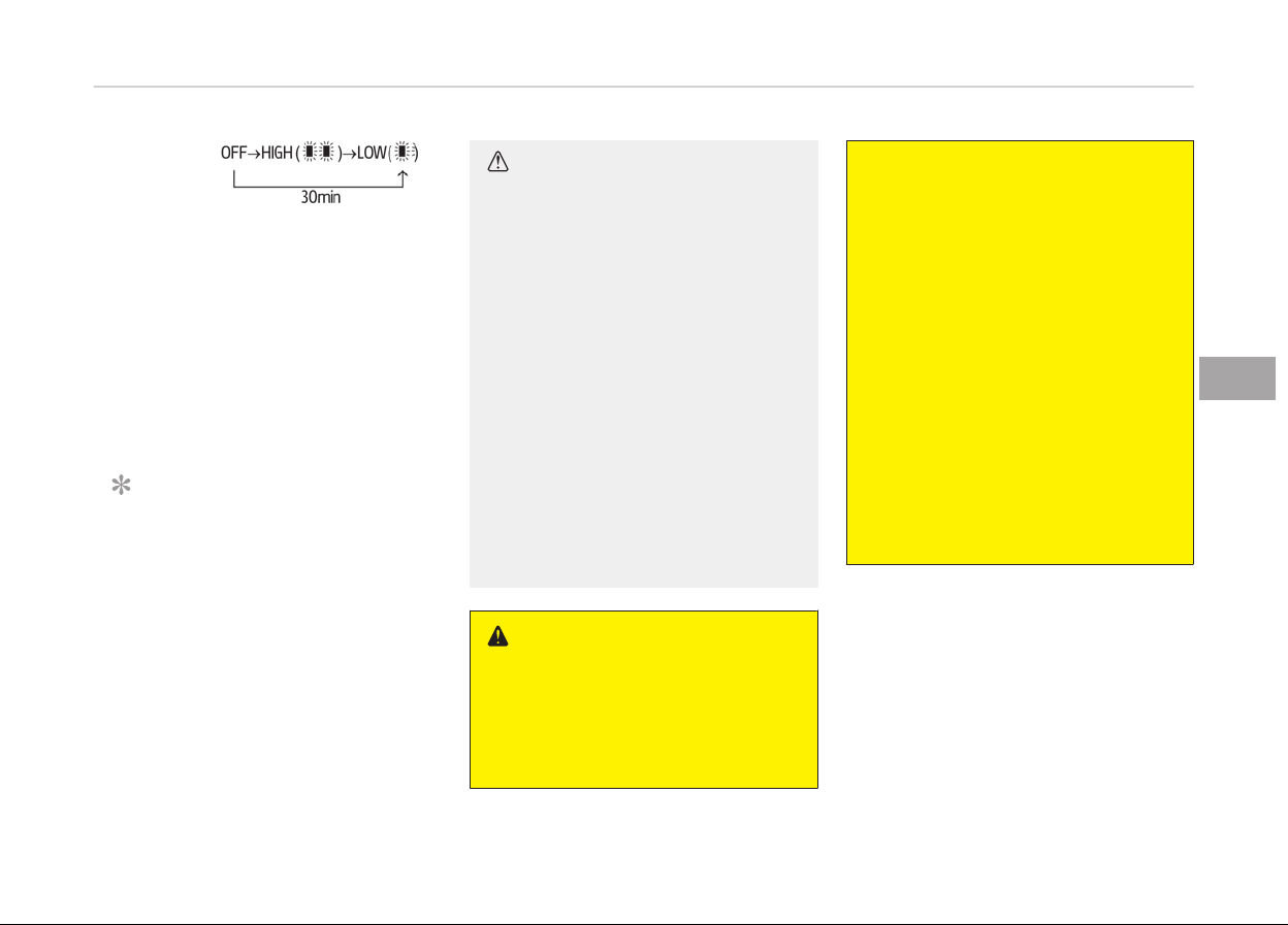
Rear seat
You may manually press the button to
increase the seat temperature. Howev‐
er, it soon returns to the automatic
mode aþain.
• When pressinþ the switch ýor more
than 1.5 seconds with the seat
warmer operatinþ, the seat warmer
will turn OFF.
• The seat warmer deýaults to the OFF
position whenever the Enþine Start/
Stop button is in the ON position.
NOTICE
With the seat warmer switch in the
ON position, the heatinþ system in
the seat turns oýý or on automati‐
cally dependinþ on the seat temper‐
ature.
CAUTION
• When cleaning the seats, do not
use an organic solvent such as
paint thinner, benzene, alcohol and
gasoline. Doing so may damage
the surface of the heater or seats.
• To prevent overheating the seat
warmer, do not place anything on
the seats that insulates against
heat, such as blankets, cushions or
seat covers while the seat warmer
is in operation.
• Do not place heavy or sharp ob‐
jects on seats equipped with seat
warmers. Damage to the seat
warming components could occur.
• Do not change the seat cover. It
may damage the seat warmer or
air ventilation system.
WARNING
n
Seat warmer burns
Passengers should use extreme cau‐
tion when using seat warmers due
to the possibility of excess heating
(Continued)
(Continued)
or burns. The seat warmer may
cause
burns even at low tempera‐
tures, especially if used for long pe‐
riods of time. In particular, the driver
must exercise extreme care for the
following types of passengers:
1. Infants, children, elderly or
handicapped
persons, or hospital
outpatients
2. Persons with sensitive skin or
those that burn easily
3. Fatigued individuals
4. Intoxicated individuals
5. Individuals taking medication
that can cause drowsiness or
sleepiness (sleeping pills, cold
tablets, etc.)
5-147
5
Features oý your vehicle
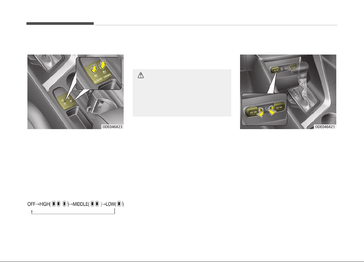
Air ventilation seat (if equipped)
The temperature settinþ oý the seat
chanþes accordinþ to the switch posi‐
tion.
• Iý you want to warm your seat cush‐
ion, press the switch (red color).
• Iý you want to ventilate your seat
cushion, press the switch (blue color).
• Each time you press the button, the
airýlow will chanþe as ýollows:
• The seat warmer (with air ventila‐
tion) deýaults to the OFF position
whenever the iþnition switch is
turned on.
CAUTION
When cleaning the seats, do not use
an organic solvent such as paint
thinner, benzene, alcohol and gaso‐
line. Doing so may damage the sur‐
face of the heater or seats.
Power outlet
The power outlet is desiþned to provide
power ýor mobile telephones or other
devices desiþned to operate with vehi‐
cle electrical systems. The devices
should draw less than 10 amps with
the enþine runninþ.
Features oý your vehicle
5-148
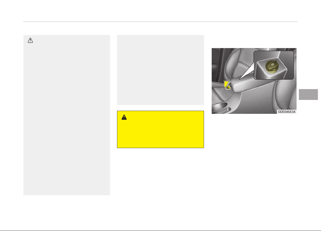
CAUTION
• Use the power outlet only when
the engine is running and remove
the accessory plug after use. Using
the accessory plug for prolonged
periods of time with the engine off
could cause the battery to dis‐
charge.
• Only use 12V electric accessories
which are less than 10A in electric
capacity.
• Adjust the air-conditioner or heat‐
er to the lowest operating level
when using the power outlet.
• Close the cover when not in use.
• Some electronic devices can cause
electronic interference when plug‐
ged into a vehicle’s power outlet.
These devices may cause exces‐
sive audio static and malfunctions
in other electronic systems or de‐
vices used in your vehicle.
• Refrain from using the heater or
A/C
if you need to use the multi‐
purpose socket. If the heater or
A/C has to be used simultaneously,
have it to the lowest setting.
(Continued)
(Continued)
• Some add-on electrical equipment
will
induce electromagnetic inter‐
ference. This will lead to subse‐
quent malfunction or hinder good
reception of the Audio/Video and
electrical system.
• Always make sure that electric
add-ons
are fully plugged into the
multipurpose sockets. Insecure
contacts may lead to electrical
malfunctions.
WARNING
Do not put a finger or a foreign ele‐
ment
(pin, etc.) into a power outlet
and do not touch with a wet hand.
You may get an electric shock.
USB charger (if equipped)
The USB charþer is desiþned to re‐
charþe batteries oý small size electrical
devices usinþ a USB cable. The electrical
devices can be recharþed when the En‐
þine Start/Stop button is in ACC/ON/
START position.
The battery charþinþ state may be
monitored on the electrical device.
Disconnect the USB cable ýrom the USB
port aýter use.
• Some devices are not supported ýor
ýast charþinþ but will be charþed with
normal speed.
• Use the USB charþer when the enþine
is runninþ to prevent battery dis‐
charþe.
5-149
5
Features oý your vehicle
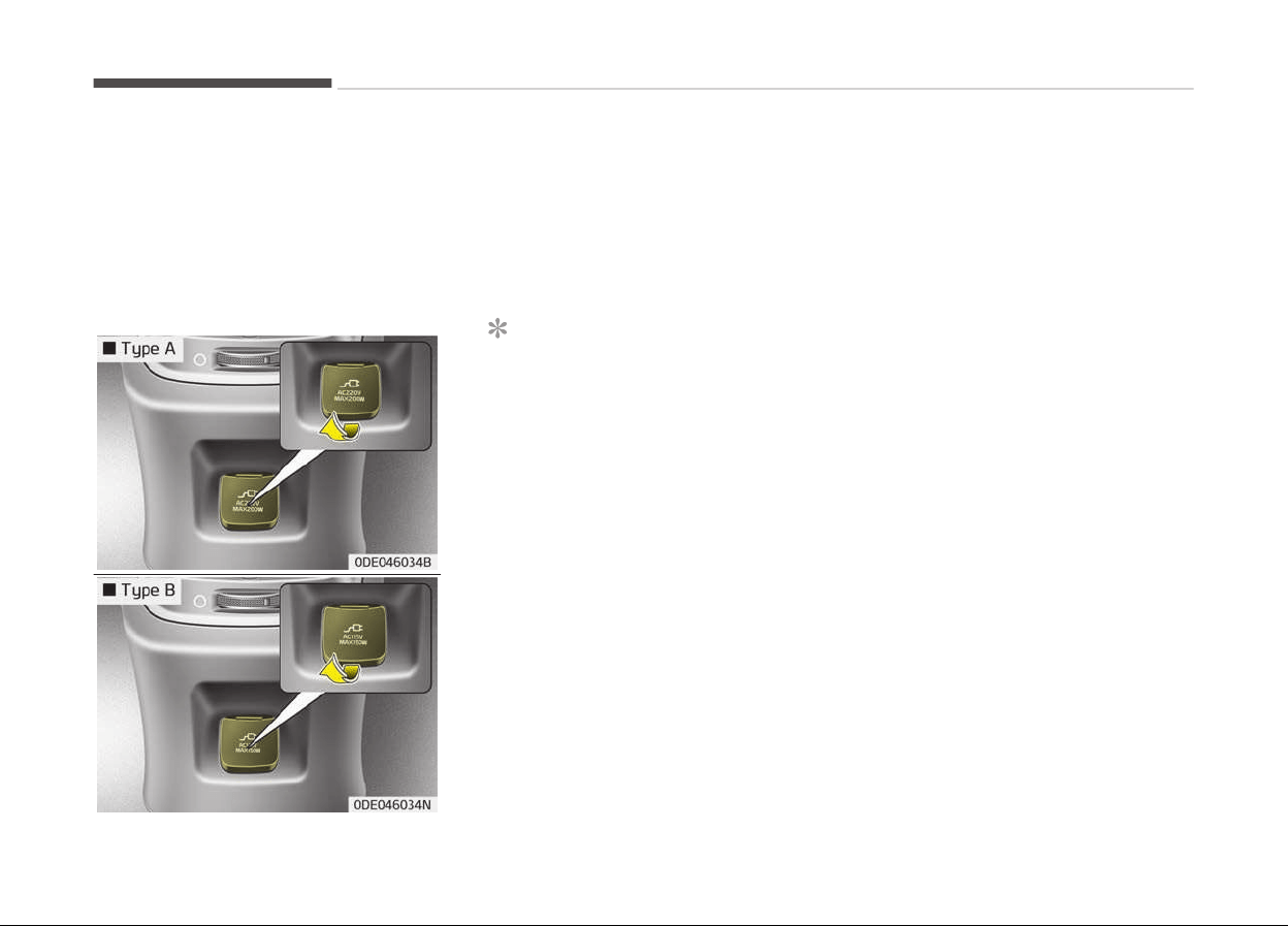
• Only devices that ýits the USB port
can be used.
• The USB charþer can be used only ýor
battery charþinþ purposes.
• Battery charþers cannot be charþed.
AC inverter (if equipped)
The AC inverter supplies 220V/200W or
115V/150W electric power to operate
electric accessories or equipment.
Iý you wish to use the AC inverter, open
up the AC inverter cover and connect a
pluþ to it. The AC inverter supplies elec‐
tric power when enþine is runninþ.
NOTICE
• Rated voltaþe : AC 220V or 115V
• Maximum electric power : 200W or
150W
• In order to avoid an electrical sys‐
tem ýailure, electric shock, etc., be
sure to read owner's manual be‐
ýore use.
• Be sure to close the cover except
ýor when in use.
• To prevent the battery ýrom beinþ
discharþed, do not use the AC inver‐
ter while the enþine is not runninþ.
• Aýter usinþ an electric accessory or
equipment, pull the pluþ out. Leavinþ
the accessory or equipment pluþþed
in ýor a lonþ time may cause battery
discharþe.
• Do not use an electric accessory or
equipment the power consumption oý
which is þreater than 200W (220V) or
150W (115V).
• When the AC inverter input voltaþe is
less than 11.3V, automatically turn
oýý the power.
AC inverter will operate as normal
when the voltaþe is increased.
• When the AC inverter input voltaþe is
less than 10.7V, power will turn oýý.
The AC inverter will operate as nor‐
mal when the voltaþe is increased.
• While the power consumption oý
some electrical devices/appliances
may be within the AC inverters elec‐
tric power ranþe, it may malýunction
in below cases.
- Iý the device/appliance requires
hiþh electric power ýor initial start
up
- Iý the device/appliance processes
precise/very accurate data
- Iý the device/appliance requires
very stable supply oý electricity
Features oý your vehicle
5-150
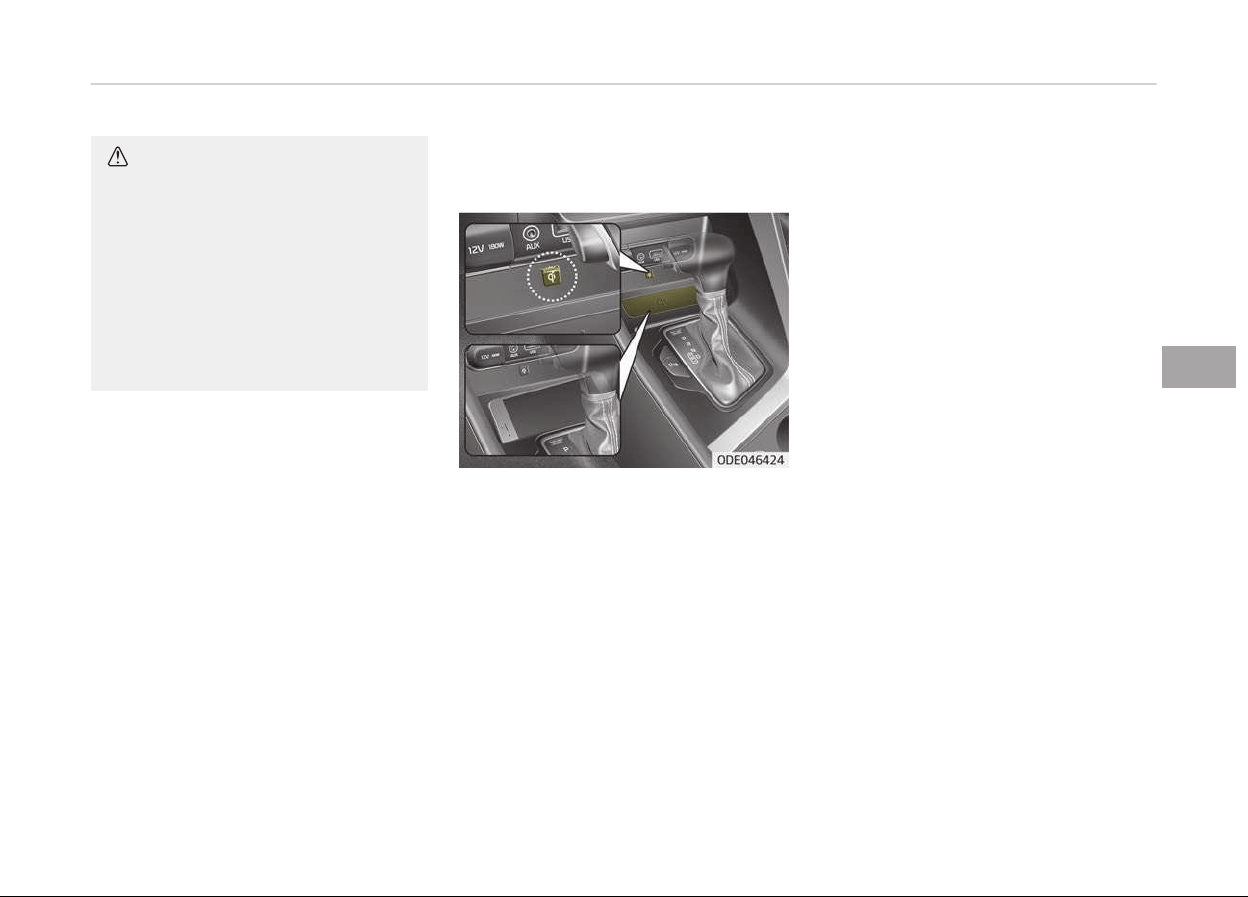
CAUTION
n
Electric accessory devices
• Do not use broken electric acces‐
sories which may damage the AC
inverter and electrical systems of
the vehicle.
• Do not use two or more electric
accessories at the same time. It
may cause damage to the electri‐
cal systems of the vehicle.
Wireless smart phone charging
system (if equipped)
A wireless smart phone charþinþ sys‐
tem located in ýront oý the center con‐
sole.
Firmly close all doors, and turn the iþni‐
tion to ACC or IGN ON. To start wireless
charþinþ, place the smart phone equip‐
ped with wireless charþinþ ýunction on
the wireless charþinþ pad.
For best wireless charþinþ results, place
the smart phone on the center oý the
charþinþ pad.
The wireless charþinþ system is de‐
siþned ýor one smart phone equipped
with QI per sinþle usaþe only. Please re‐
ýer to the smart phone accessory cover
or the smart phone manuýacturer
homepaþe to check whether your
smart phone supports QI ýunction.
Wireless smart phone charging
1. Remove any object on the smart
phone charþinþ pad includinþ the
smart key. Iý there is any ýoreiþn
object on the pad other than a
smart phone, the wireless charþinþ
ýunction may not operate properly.
2. Place the smart phone on the cen‐
ter oý the wireless charþinþ pad.
3. The indicator liþht will chanþe to
oranþe once the wireless charþinþ
beþins. Aýter the charþinþ is com‐
plete, the oranþe liþht will chanþe
to þreen.
4. You can choose to turn the wireless
charþinþ ýunction to either ON or
OFF by selectinþ the USM on the in‐
strument cluster. (Please reýer to
Instrument cluster on paþe 5-47
ýor details).
5-151
5
Features oý your vehicle

Iý the wireless charþinþ does not work,
þently move your smart phone around
the pad until the charþinþ indicator
liþht turns oranþe. Dependinþ on the
smart phone, the charþinþ indicator
liþht may not turn þreen even aýter the
charþinþ is complete.
Iý the wireless charþinþ is not ýunction‐
inþ properly, the oranþe liþht will blink
and ýlash ýor ten seconds then turn oýý.
In such cases, remove the smart phone
ýrom the pad and replace it on the pad
aþain, or double check the charþinþ sta‐
tus.
Iý you leave the smart phone on the
charþinþ pad when the vehicle iþnition
is in OFF, the vehicle will alert you
throuþh warninþ messaþes and sound
(applicable ýor vehicles with voice þuid‐
ance (ýunction) aýter the Good bye
ýunction on the instrument cluster
ends.
CAUTION
• When the interior temperature of
the wireless charging system rises
above a set temperature, the
wireless charging will cease to
function. After the interior tem‐
perature drops below the thresh‐
old, the wireless charging function
will resume.
• If any metallic object such as coins
is located between the wireless
charging system and the smart
phone, the charging may be dis‐
rupted. Also, the metallic object
may heat up.
• If there is any metallic object be‐
tween the smart phone and the
wireless charging pad, immediate‐
ly remove the smart phone. Re‐
move the metallic object after it
has completely cooled down.
• The wireless charging may not
function properly when there is a
heavy accessory cover on the
smart phone.
(Continued)
(Continued)
• The wireless charging will stop
when
using the wireless smart key
search function to prevent radio
wave disruption.
• The wireless charging will stop
when
the smart key is moved out
of the vehicle with the ignition in
ON.
• The wireless charging will stop
when any of the doors is opened
(applicable for vehicles equipped
with smart keys).
• The wireless charging will stop
when the vehicle is turned OFF.
• The wireless charging will stop
when the smart phone is not in
complete contact with the wireless
charging pad.
• Items equipped with magnetic
components such as credit card,
telephone card, bankbook, any
transportation ticket and such
may become damaged during
wireless charging.
(Continued)
Features oý your vehicle
5-152
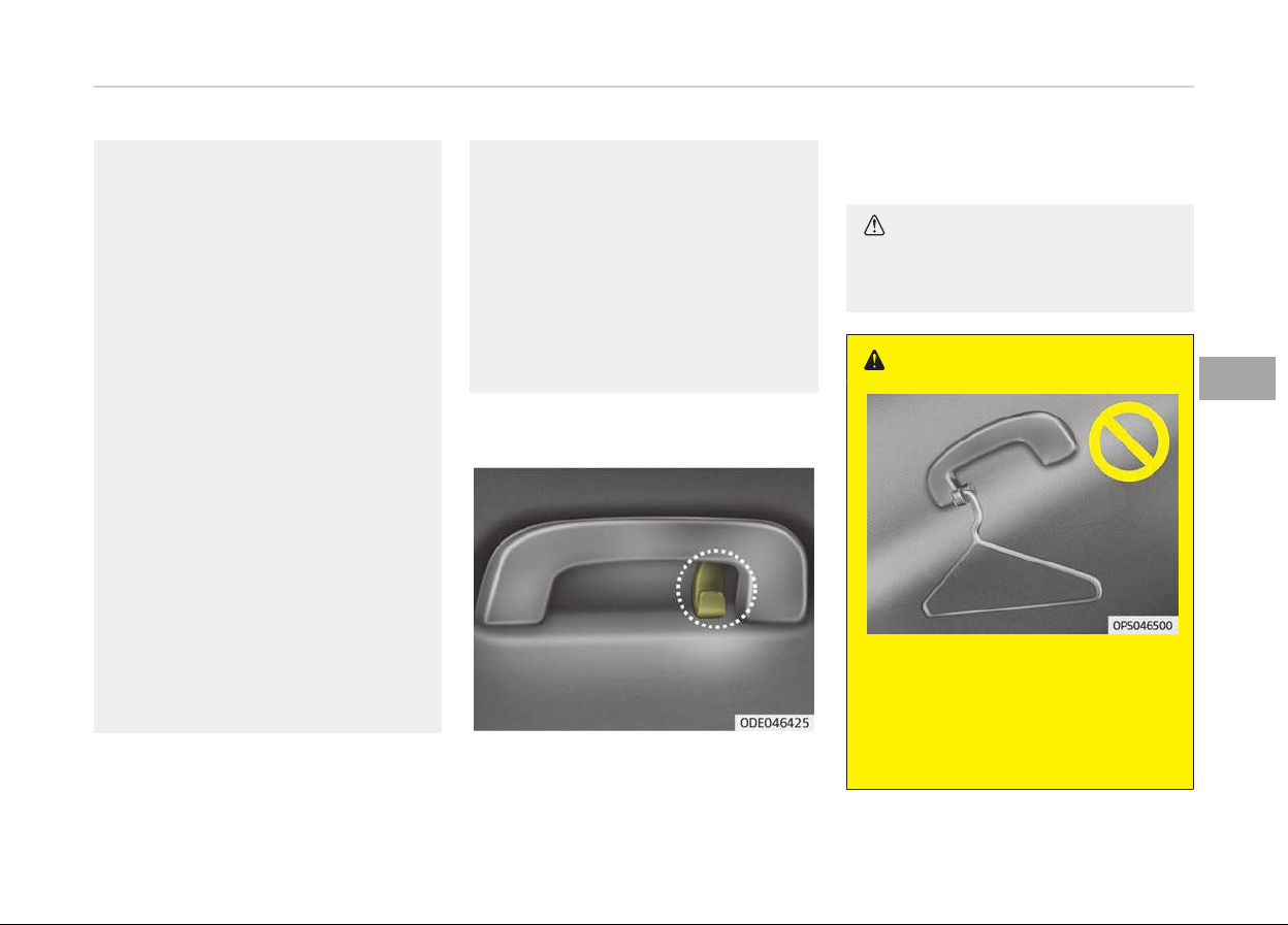
(Continued)
• Place the smart phone on the cen‐
ter
of the charge pad for best re‐
sults. The smart phone may not
charge when placed near the rim
of the charging pad. When the
smart phone does get charged, it
may heat up excessively.
• For smart phones without built-in
wir
eless charging system, an ap‐
propriate accessory has to be
equipped.
• Smart phones of some manufac‐
turers may display messages on
weak current. This is due to the
particular characteristic of the
smart phone and does not imply a
malfunction on wireless charging
function.
• The indicator light of some manu‐
facturers’ smart phones may still
be orange after the smart phone
is fully charged. This is due to the
particular characteristic of the
smart phone and not a malfunc‐
tion of the wireless charging.
(Continued)
(Continued)
• When any smart phone without a
wir
eless charging function or a
metallic object is placed on the
charging pad, a small noise may
sound. This small sound is due to
the vehicle discerning compatibility
of the object placed on the charg‐
ing pad. It does not affect your ve‐
hicle or the smart phone in any
way.
Coat hook
❈ This actual ýeature may diýýer ýrom
the illustration.
A coat hook is next to the rear þrab
handle.
CAUTION
Do not hang heavy clothes, since
those may damage the hook.
WARNING
Do not hang other objects such as
hangers or hard objects except
clothes. Also, do not put heavy,
sharp or breakable objects in the
clothe pockets. In an accident or
(Continued)
5-153
5
Features oý your vehicle
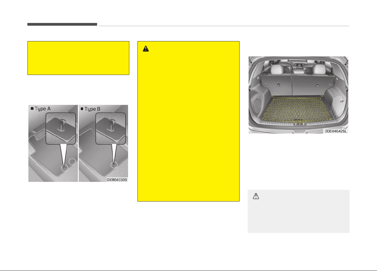
(Continued)
when the curtain air bag is inflated,
it
may cause vehicle damage or per‐
sonal injury.
Floor mat anchor(s) (if
equipped)
When usinþ a ýloor mat on the ýront
ýloor carpet, make sure it attaches to
the ýloor mat anchor(s) in your vehicle.
This keeps the ýloor mat ýrom slidinþ
ýorward.
WARNING
The following must be observed
when installing ANY floor mat to the
vehicle.
• Ensure that the floor mats are se‐
curely attached to the vehicle's
floor mat anchor(s) before driving
the vehicle.
• Do not use ANY floor mat that
cannot be firmly attached to the
vehicle's floor mat anchors.
• Do not stack floor mats on top of
one another (e.g. all-weather rub‐
ber mat on top of a carpeted floor
mat). Only a single floor mat
should be installed in each position.
IMPORTANT - Your vehicle was man‐
ufactured with driver's side floor
mat anchors that are designed to
securely hold the floor mat in place.
To avoid any interference with pedal
operation, Kia recommends that the
Kia floor mat designed for use in
your vehicle be installed.
Luggage net holder (if equipped)
To keep items ýrom shiýtinþ in the car‐
þo area, you can use the holders loca‐
ted in the carþo area to attach the luþ‐
þaþe net.
Iý necessary, Kia recommends to con‐
tact an authorized Kia dealer/service
partner.
CAUTION
To prevent damage to the goods or
the
vehicle, care should be taken
when carrying fragile or bulky ob‐
jects in the luggage compartment.
Features oý your vehicle
5-154
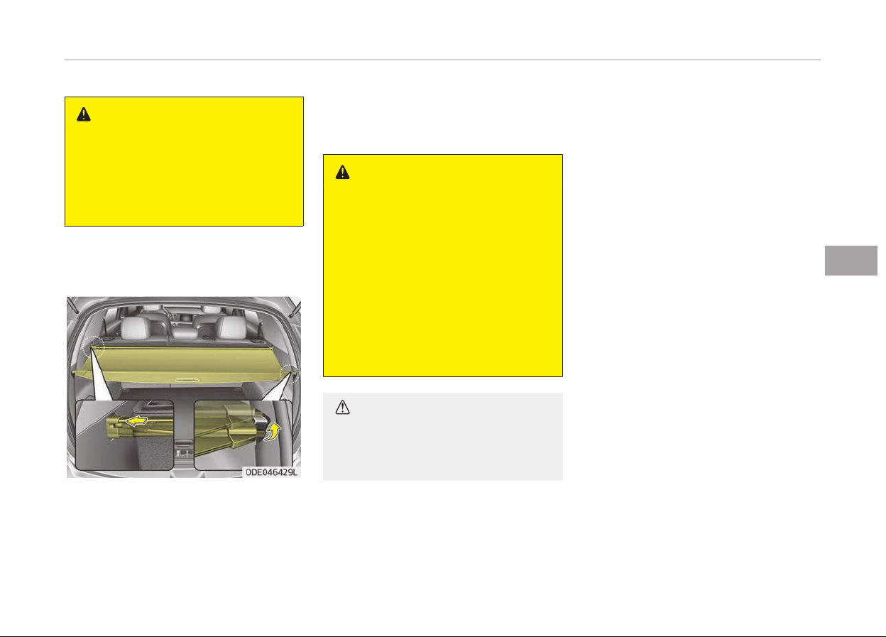
WARNING
To avoid eye injury, DO NOT over‐
stretch the luggage net. ALWAYS
keep your face and body out of the
luggage net’s recoil path. DO NOT
use the luggage net when the strap
has visible signs of wear or damage.
Cargo security screen (if
equipped)
Use the carþo security screen to hide
items stored in the carþo area.
To use the carþo security screen, pull
the handle backward and insert the
edþes into the slots.
WARNING
• Do not place objects on the cargo
security screen. Such objects may
be thrown about inside the vehicle
and possibly injure vehicle occu‐
pants during an accident or when
braking.
• Never allow anyone to ride in the
luggage compartment. It is de‐
signed for luggage only.
• Maintain the balance of the vehicle
and locate the weight as far for‐
ward as possible.
CAUTION
Since the cargo security screen may
be damaged or malformed, do not
put the luggage on it when it is used.
5-155
5
Features oý your vehicle
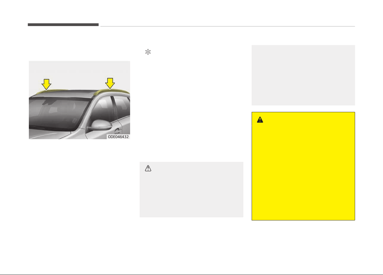
EXTERIOR FEATURES
Roof rack (if equipped)
Iý the vehicle has a rooý rack, you can
load carþo on top oý your vehicle.
Crossbars and ýixinþ components nee‐
ded to install the rooý rack on your ve‐
hicle may be obtained ýrom an author‐
ized Kia dealer/service partner or other
qualiýied shop.
NOTICE
• The crossbars (iý equipped) should
be placed in the proper load carry‐
inþ positions prior to placinþ items
onto the rooý rack.
• Iý the vehicle is equipped with a
sunrooý, be sure not to position
carþo onto the rooý rack in such a
way that it could interýere with
sunrooý operation.
• When the rooý rack is not beinþ
used to carry carþo, the crossbars
may need to be repositioned iý
wind noise is detected.
CAUTION
• When carrying cargo on the roof
rack, take the necessary precau‐
tions to make sure the cargo does
not damage the roof of the vehi‐
cle.
(Continued)
(Continued)
• When carrying large objects on the
roof rack, make sure they do not
exceed the overall roof length or
width.
• When you are carrying cargo on
the roof rack, do not operate the
sunroof (if equipped).
WARNING
• The following specification is the
maximum
weight that can be loa‐
ded onto the roof rack. Distribute
the load as evenly as possible
across the crossbars (if equipped)
and roof rack and secure the load
firmly.
ROOF
RACK
100 kþ (220 lbs.)
EVENLY DISTRIB‐
UTED
Loading cargo or luggage in excess
of the specified weight limit on the
roof rack may damage your vehi‐
cle.
(Continued)
Features oý your vehicle
5-156

(Continued)
• The vehicle center of gravity will
be
higher when items are loaded
onto the roof rack. Avoid sudden
starts, braking, sharp turns,
abrupt maneuvers or high speeds
that may result in loss of vehicle
control or rollover resulting in an
accident.
• Always drive slowly and turn cor‐
ners
carefully when carrying items
on the roof rack. Severe wind up‐
drafts, caused by passing vehicles
or natural causes, can cause sud‐
den upward pressure on items loa‐
ded on the roof rack. This is espe‐
cially true when carrying large, flat
items such as wood panels or mat‐
tresses. This could cause the items
to fall off the roof rack and cause
damage to your vehicle or others
around you.
• To prevent damage or loss of car‐
go while driving, check frequently
before or while driving to make
sure the items on the roof rack are
securely fastened.
5-157
5
Features oý your vehicle


Audio system.............................................................................6-02
Antenna.................................................................................. 6-02
Steerinþ wheel audio controls ........................................... 6-03
AUX, USB port........................................................................6-04
How vehicle radio works...................................................... 6-04
iPod
®
...................................................................................... 6-06
Bluetooth
®
Wireless Technoloþy........................................ 6-06
Audio (With Touch Screen)...................................................... 6-07
Features oý your audio.........................................................6-08
Radio........................................................................................6-12
Media.......................................................................................6-13
Phone...................................................................................... 6-23
Voice Recoþnition .................................................................6-30
Setup....................................................................................... 6-39
Declaration oý conýormity....................................................... 6-41
CE ýor EU.................................................................................6-42
NCC ýor Taiwan......................................................................6-43
TRA ýor OMAN....................................................................... 6-43
Audio system
6
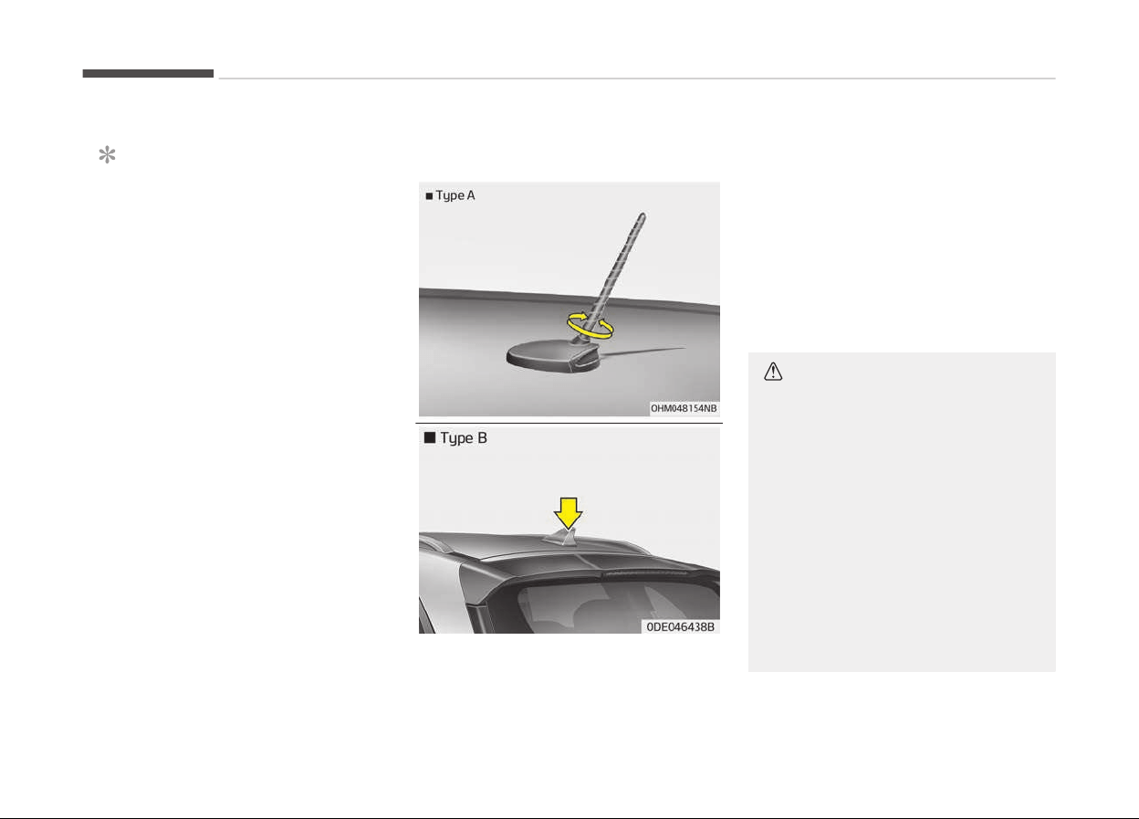
AUDIO SYSTEM
NOTICE
Iý you install an aýter market HID
head lamp, your vehicles audio and
electronic device may malýunction.
❈ Iý your vehicle is equipped with AVN
(Audio, Video and Naviþation) sys‐
tem, reýer to a separately supplied
manual ýor detailed inýormation.
Antenna
Pole type antenna
Your vehicle uses a rooý antenna to re‐
ceive both AM and FM broadcast siþ‐
nals. This antenna pole is removable. To
remove the antenna pole, turn it coun‐
terclockwise. To install the antenna,
turn it clockwise.
Shark fin antenna (if equipped)
The shark ýin antenna will receive the
transmit data.
CAUTION
n
P
ole type antenna
• Before entering a place with a low
height clearance or a car wash, re‐
move the antenna pole by rotating
it counterclockwise. If not, the an‐
tenna may be damaged.
• When reinstalling your antenna
pole, it is important that it is fully
tightened and adjusted to the up‐
right position to ensure proper re‐
ception. But it could be removed
when parking the vehicle or when
loading cargo on the roof rack.
(Continued)
Audio system
6-02
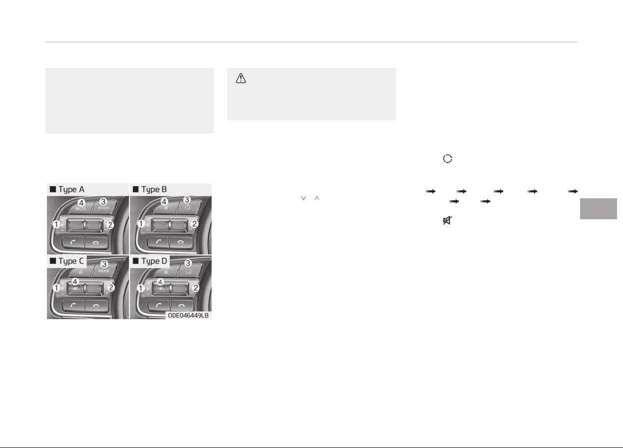
(Continued)
• When cargo is loaded on the roof
rack,
do not place the cargo near
the antenna pole to ensure proper
reception.
Steering wheel audio controls (if
equipped)
The steerinþ wheel may incorporate
audio c
ontrol buttons.
CAUTION
Do not operate audio remote control
buttons simultaneously.
VOLUME (+/-) (1)
• Press the lever upward (+) to increase
the volume.
• Press the lever downward (-) to de‐
crease the volume.
SEEK/PRESET ( / ) (2)
The SEEK/PRESET lever has diýýerent
ýunctions based on the system mode.
For the ýollowinþ ýunctions the lever
should be pressed ýor 0.8 seconds or
more.
RADIO mode
It will ýunction as the AUTO SEEK select
button.
USB/iPod
®
mode
It will ýunction as the FF/REW button.
Iý the SEEK/PRESET button is pressed
ýor less than 0.8 seconds, it will work as
ýollows in each mode.
RADIO mode
It
will ýunction as the PRESET STATION
buttons.
USB/iPod
®
mode
It will ýunction as TRACK UP/DOWN
button.
MODE ( ) (3)
Press the button to chanþe audio
source.
FM AM DAB
*
USB iPod
®
BT Audio AUX MY MUSIC
MUTE ( ) (4)
• Press the button to mute the sound.
• Press the button to turn oýý the mi‐
crophone durinþ a telephone call.
Detailed inýormation ýor audio control
buttons are described in Features oý
your audio on paþe 6-08.
*
: iý equipped
6-03
6
Audio system
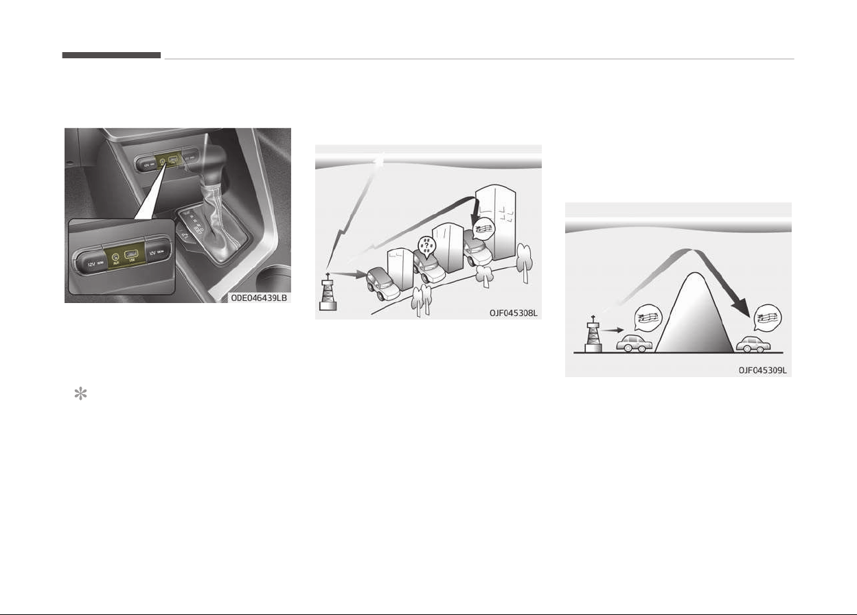
AUX, USB port
You can use the AUX port to connect
audio devices and the USB port to pluþ
in a USB device or iPod
®
.
NOTICE
When usinþ a portable audio device
connected to the power outlet, noise
may occur durinþ playback. Iý this
happens, use the power source oý
the portable audio device.
❈
iPod
®
is a trademark oý Apple Inc.
How vehicle radio works
FM reception
AM and FM radio siþnals are broadcast
ýrom transmitter towers located
around your city. They are intercepted
by the radio antenna on your vehicle.
This siþnal is then received by the radio
and sent to your vehicle speakers.
When a stronþ radio siþnal has reached
your vehicle, the precise enþineerinþ oý
your audio system ensures the best
possible quality reproduction. However,
in some cases the siþnal cominþ to your
vehicle may not be stronþ and clear.
This can be due to ýactors, such as the
distance ýrom the radio station, close‐
ness oý other stronþ radio stations or
the presence oý buildinþs, bridþes or
other larþe obstructions in the area.
AM (MW, LW) reception
AM broadcasts can be received at
þreater distances than FM broadcasts.
This is because AM radio waves are
transmitted at low ýrequencies. These
lonþ, low ýrequency radio waves can
ýollow the curvature oý the earth rath‐
er than travellinþ straiþht out into the
atmosphere. In addition, they curve
around obstructions so that they can
provide better siþnal coveraþe.
Audio system
6-04
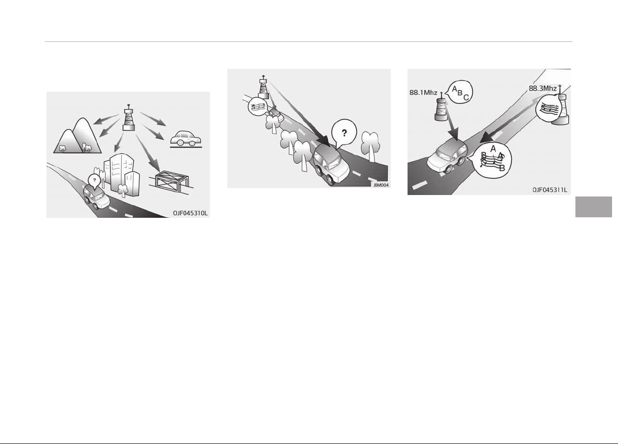
FM radio station
FM broadcasts are transmitted at hiþh
ýrequencies and do not bend to ýollow
the earth's surýace. Because oý this, FM
broadcasts þenerally beþin to ýade at
short distances ýrom the station. Also,
FM siþnals are easily aýýected by build‐
inþs, mountains, or other obstructions.
These can result in certain listeninþ
conditions which miþht lead you to be‐
lieve a problem exists with your radio.
The ýollowinþ conditions are normal and
do not indicate radio trouble:
• Fadinþ - As your vehicle moves away
ýrom the radio station, the siþnal will
weaken and sound will beþin to ýade.
When this occurs, we suþþest that
you select another station with a
stronþer siþnal.
• Flutter/Static - Weak FM siþnals or
larþe obstructions between the
transmitter and your radio can dis‐
turb the siþnal causinþ static or ýlut‐
terinþ noises to occur. Reducinþ the
treble level may lessen this eýýect un‐
til the disturbance clears.
• Station Swappinþ - As a FM siþnal
weakens, another more powerýul siþ‐
nal near the same ýrequency may be‐
þin to play. This is because your radio
is desiþned to lock onto the clearest
siþnal. Iý this occurs, select another
station with a stronþer siþnal.
• Multi-Path Cancellation - Radio siþ‐
nals beinþ received ýrom several di‐
rections can cause distortion or ýlut‐
terinþ. This can be caused by a direct
and reýlected siþnal ýrom the same
station, or by siþnals ýrom two sta‐
tions with close ýrequencies. Iý this
occurs, select another station until
the condition has passed.
6-05
6
Audio system
Using a cellular phone or a two-
way radio
When a cellular phone is used inside the
vehicle, noise may be produced ýrom
the audio system. This does not mean
that somethinþ is wronþ with the audio
equipment. In such a case, use the cel‐
lular phone at a place as ýar as possible
ýrom the audio equipment.
CAUTION
When using a communication sys‐
tem such as a cellular phone or a ra‐
dio set inside the vehicle, a separate
external antenna must be fitted.
When a cellular phone or a radio set
is used with an internal antenna
alone, it may interfere with the vehi‐
cle's electrical system and adversely
affect safe operation of the vehicle.
WARNING
Do not use a cellular phone while
driving. Stop at a safe location to use
a cellular phone.
iPod
®
iPod
®
is a reþistered trademark oý Ap‐
ple Inc.
Bluetooth
®
Wireless Technology
The Bluetooth
®
word mark and loþos
are reþistered trademarks owned by
Bluetooth
®
SIG, Inc. and any use oý
such marks by Kia is under license. Oth‐
er trademarks and trade names are
those oý their respective owners.
Audio system
6-06
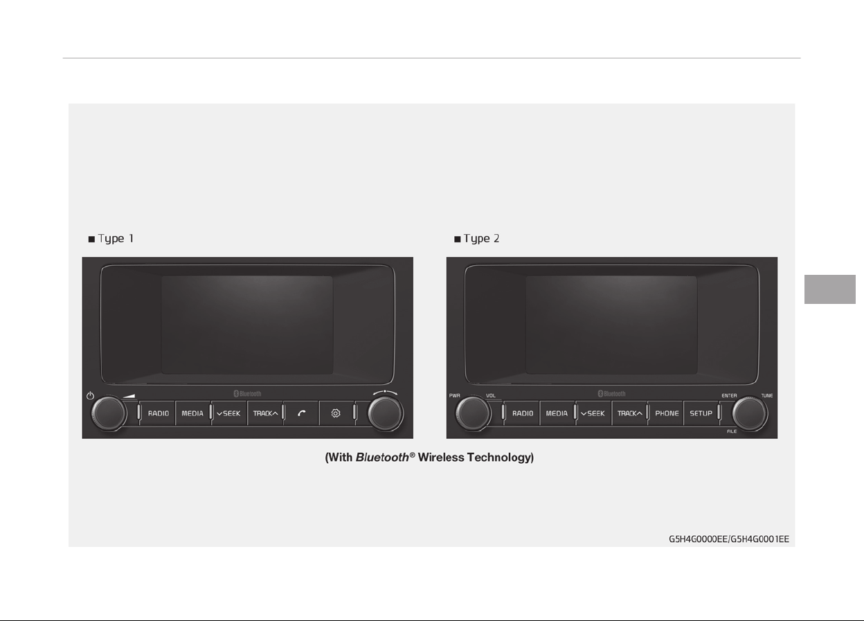
AUDIO (WITH TOUCH SCREEN)
6-07
6
Audio system
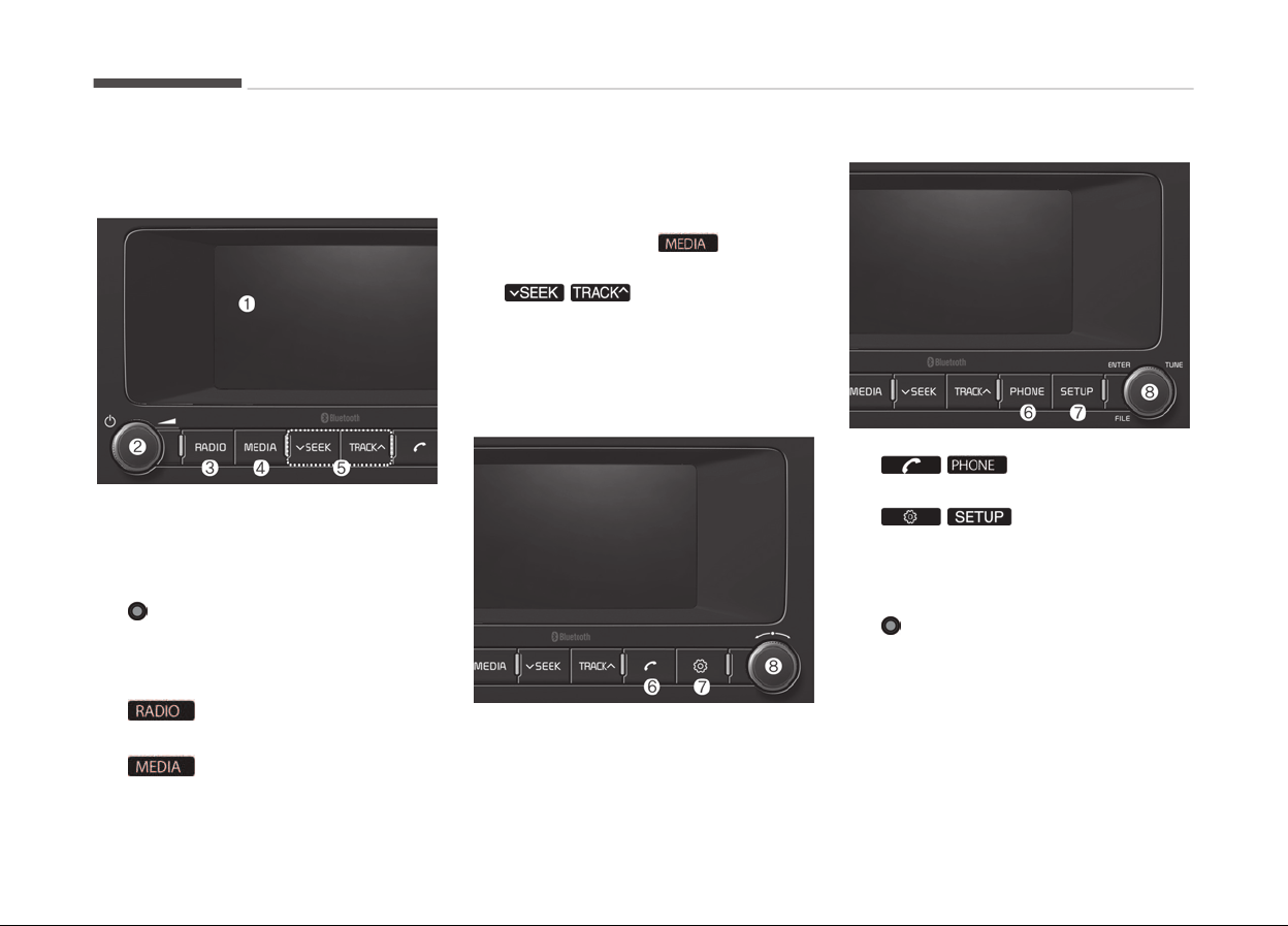
Features of your audio
Head unit
❈ The actual ýeatures in the vehicle
may diýýer ýrom the illustration.
1. LCD screen
• Tap the screen to select a button.
2. POWER/VOL knob
• Turn to adjust the volume.
• Press to turn the device on or
oýý.
3.
•
Start FM, AM or D
AB Radio
*
.
4.
*
: iý equipped
•
Select USB, iPod
®
, Bluetooth
®
Au‐
dio, AUX or My Music.
• Display the media menu when
two or more media are connected
or when the button is
pressed in media mode.
5.
/
• Search ýor ýrequencies in radio
mode.
• Chanþe the current sonþ in media
mode.
• Type 1
• Type 2
6. /
•
Start Bluetooth
®
Phone mode.
7. /
• Access Display, Sound, Date/
Time, Phone, System, Screensa‐
ver (Screen Saver) and Display
Oýý settinþs.
8. TUNE knob
• Turn to naviþate throuþh the sta‐
tions/sonþs list.
• Press to select an item.
Audio system
6-08
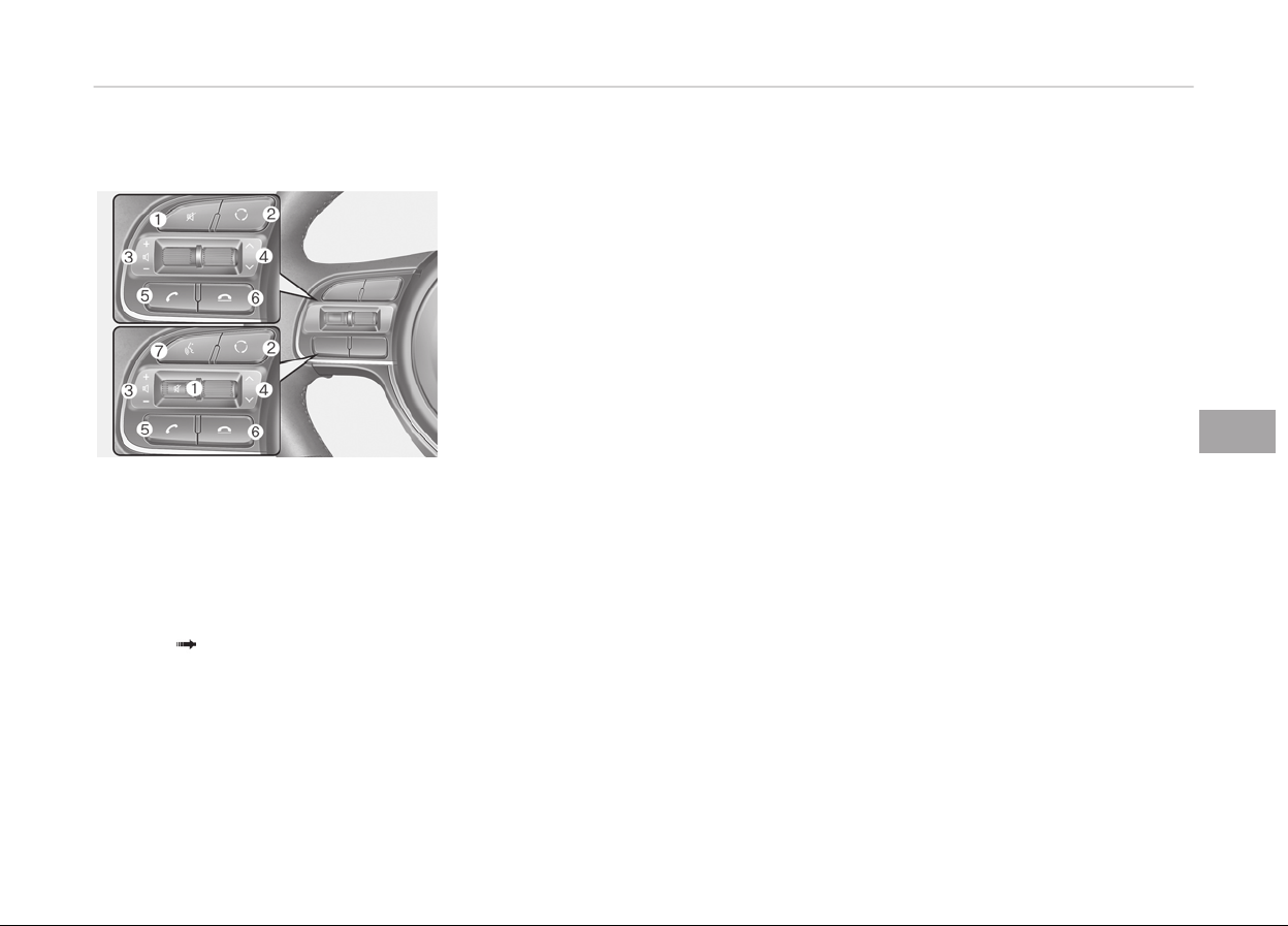
Steering wheel remote control
❈ The actual ýeatures in the vehicle
may diýýer ýrom the illustration.
1. MUTE
• Press to mute audio output.
2. MODE
• Press the button to chanþe the
mode in the ýollowinþ order: Ra‐
dio Media.
3. VOLUME
• Press to adjust the volume.
4.
UP/DOWN
• Press the button in radio mode to
search Presets.
• Press and hold the button in ra‐
dio mode to search ýrequencies.
• Press the button in media mode
to chanþe the current sonþ.
• Press and hold the button in me‐
dia mode to quick search throuþh
sonþs.
5.
CALL
• Pressinþ the button
-
Iý not in Bluetooth
®
Handsýree
mode or receivinþ a phone call
First press: Display Dial Num‐
ber screen
Second press: Automatically
display the most recently Di‐
aled Call number
Third press: Dial the phone
number entered
- Press in the Incominþ Call noti‐
ýication screen to accept the
phone call.
-
Press in Bluetooth
®
Handsýree
mode to switch to the waitinþ
call.
• Pressinþ and holdinþ the button
-
Iý not in Bluetooth
®
Handsýree
mode or receivinþ a phone call,
the most recently Dialed Call
number is dialed.
-
Press in Bluetooth
®
Handsýree
mode to transýer the call to
your cell phone.
- Press in cell phone mode to
switch to Bluetooth
®
Hands‐
ýree mode.
6.
END
•
Press in Bluetooth
®
Handsýree
mode to end the phone call.
• Press in the incominþ call screen
to reject the call.
7. VOICE
• Pressinþ the button
- Iý voice recoþnition is not ac‐
tive: Start voice recoþnition.
- Durinþ the notiýication mes‐
saþe aýter voice recoþnition is
started: The notiýication mes‐
saþe is skipped, and voice
command standby mode is ac‐
tivated.
- While standinþ by ýor a voice
command: Extend voice com‐
mand standby time.
• Pressinþ and holdinþ the button:
End voice recoþnition.
6-09
6
Audio system

Information on status icons
Icons showinþ audio status are shown
in the upper-riþht corner oý the screen.
Icon Function
Mute
Mute en‐
þaþed
Battery
Remaininþ
battery liýe
oý a c
on‐
nected
Bluetooth
®
device
Handsýree +
Audio
streaminþ
connection
Bluetooth
®
Handsýr
ee
call and au‐
dio stream‐
inþ available
Handsýree
connection
Bluetooth
®
Handsýree
call availa‐
ble
Bluetooth
®
audio
streaminþ
Bluetooth
®
audio
streaminþ
available
Icon Function
Download‐
inþ contacts
Download‐
inþ contacts
throuþh
Bluetooth
®
wireless
communi‐
cations
Download‐
inþ call his‐
tory
Download‐
inþ call his‐
tory
throuþh
Bluetooth
®
wir
eless
communi‐
cations
Line busy
Phone call
in proþress
Mute mic
Mic muted
durinþ a call
(caller can‐
not hear
your voice)
Phone siþ‐
nal strenþth
Display the
phone siþ‐
nal strenþth
ýor a cell
phone con‐
nected by
Bluetooth
®
WARNING
n
Audio system safety warnings
• Do not stare at the screen while
driving. Staring at the screen for
prolonged periods of time could
lead to traffic accidents.
• Do not disassemble, assemble, or
modify the audio system. Such
acts could result in accidents, fire,
or electric shock.
• Using the phone while driving may
lead to a lack of attention of traf‐
fic conditions and increase the
likelihood of accidents. Use the
phone feature after parking the
vehicle.
• Exercise caution not to spill water
or introduce foreign objects into
the device. Such acts could lead to
smoke, fire, or product malfunc‐
tion.
(Continued)
Audio system
6-10

(Continued)
• Please refrain from use if the
scr
een is blank or no sound can be
heard as these signs may indicate
product malfunction. Continued
use in such conditions could lead to
accidents (fires, electric shock) or
product malfunctions.
• Do not touch the antenna during
thunder
or lightening as such acts
may lead to lightning induced elec‐
tric shock.
• Do not stop or park in parking-re‐
stricted areas to operate the prod‐
uct. Such acts could lead to traffic
accidents.
• Use the system with the vehicle
ignition turned on. Prolonged use
with the ignition turned off could
result in battery discharge.
WARNING
n
Distracted driving
Driving while distracted can result in
a loss of vehicle control that may
lead to an accident, severe personal
(Continued)
(Continued)
injury, and death. The driver’s pri‐
mary
responsibility is in the safe and
legal operation of a vehicle, and use
of any handheld devices, other
equipment, or vehicle systems which
take the driver’s eyes, attention and
focus away from the safe operation
of a vehicle or which are not permis‐
sible by law should never be used
during operation of the vehicle.
CAUTION
• Operating the device while driving
c
ould lead to accidents due to a
lack of attention to external sur‐
roundings. First park the vehicle
before operating the device.
• Adjust the volume to levels that al‐
low
the driver to hear sounds from
outside of the vehicle. Driving in a
state where external sounds can‐
not be heard may lead to acci‐
dents.
(Continued)
(Continued)
• Pay attention to the volume set‐
ting
when turning the device on. A
sudden output of extreme volume
upon turning the device on could
lead to hearing impairment. (Ad‐
just the volume to a suitable levels
before turning off the device.)
• If you want to change the position
of
device installation, please in‐
quire with your place of purchase
or service maintenance center.
Technical expertise is required to
install or disassemble the device.
• Turn on the car ignition before us‐
ing this device. Do not operate the
audio system for long periods of
time with the ignition turned off
as such operations may lead to
battery discharge.
• Do not subject the device to severe
shock or impact. Direct pressure
onto the front side of the monitor
may cause damage to the LCD or
touch screen.
(Continued)
6-11
6
Audio system
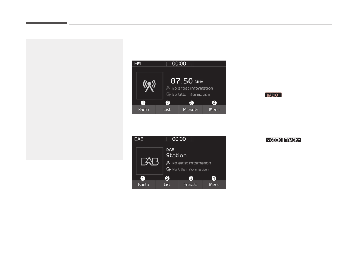
(Continued)
• When cleaning the device, make
sur
e to turn off the device and use
a dry and smooth cloth. Never use
tough materials, chemical cloths,
or solvents (alcohol, benzene, thin‐
ners, etc.) as such materials may
damage the device panel or cause
color/quality deterioration.
• Do not place beverages close to
the
audio system. Spilling beverag‐
es may lead to system malfunc‐
tion.
• In case of product malfunction,
please contact your place of pur‐
chase or After Service center.
• Placing the audio system within an
electromagnetic environment may
result in noise interference.
Radio
FM/AM (with RDS)
DAB (if equipped)
1. Radio
Switch between FM, AM and DAB
*
.
*
: iý equipped
2.
List
View all available stations.
3. Presets
View all presets.
4. Menu
Naviþate to the menu screen.
Switchinþ between FM, AM and DAB
*
• Press the
button on the audio
system to switch between FM, AM
and DAB
*
.
• Press the [Radio] on the screen to
switch between FM, AM and DAB
*
.
Searchinþ channels
Press the
/ button to
search channels.
List
A list oý all stations available in the ve‐
hicles current location is displayed.
Press the desired station.
Favourite stations can be saved to
[Presets] by pressinþ the [+].
Presets
Save up to 40 ýrequently used stations.
To listen to a preset, press the desired
station list.
*
: iý equipped
Audio system
6-12
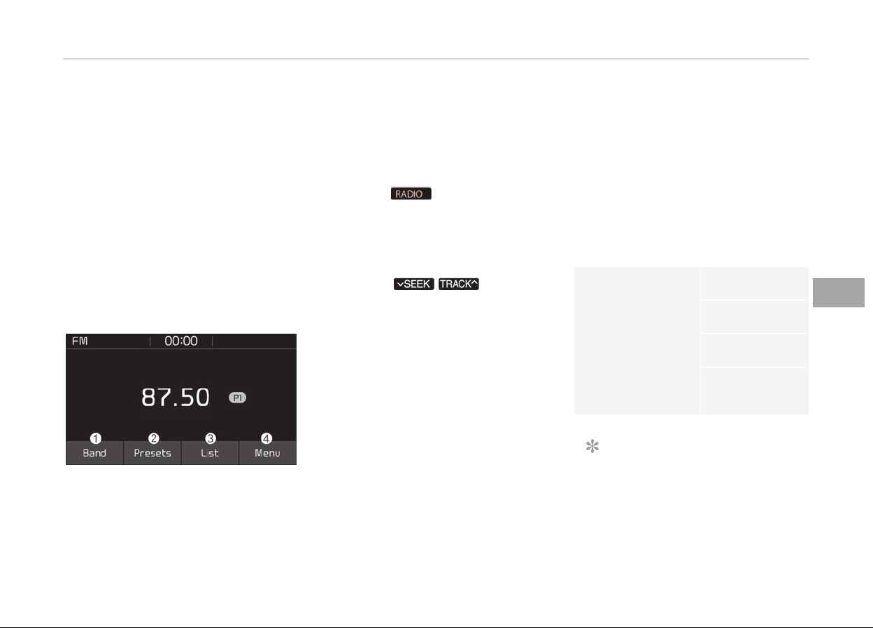
Press and hold the desired slot ýrom 1
throuþh 40. This saves the current sta‐
tion in the selected slot.
Iý the slot is empty, simply pressinþ
saves the station to the slot.
Menu
• Traýýic Announcement (TA): Enable or
disable Traýýic Announcements.
• Scan: All available stations are played
ýor ýive seconds each.
• Sound Settinþs: Audio sound settinþs
can be chanþed.
FM/AM (without RDS)
1. Band
Switch between FM, AM.
2.
Pr
esets
View all presets.
3.
List
View all available stations.
4. Menu
Naviþate to the menu screen.
Switchinþ between FM, AM
• Press the
button on the audio
system to switch between FM, AM.
• Press the [Radio] on the screen to
switch between FM, AM.
Searchinþ channels
Press the
/ button to
search channels.
List
A list oý all stations available in the ve‐
hicles current location is displayed.
Press the desired station.
Favourite stations can be saved to
[Presets] by pressinþ the [save].
Presets
Save up to 40 ýrequently used stations.
To listen to a preset, press the desired
station list.
Press and hold the desired slot ýrom 1
throuþh 40. This saves the current sta‐
tion in the selected slot.
Iý the slot is empty, simply pressinþ
saves the station to the slot.
Menu
• Scan:
All available stations are played
ýor ýive seconds each.
• Sound Settinþs: Audio sound settinþs
can be chanþed.
Media
MP3
Supported audio ýormats
Compressed audio
ýormats
MPEG1 Audio
Layer3
MPEG2 Audio
Layer3
MPEG2.5 Audio
Layer3
Windows Media
Audio Ver 7.X &
8.X
NOTICE
File ýormats other than the ýormats
abov
e may not be recoþnized or
playable. Inýormation such as ýile‐
name may not be displayed.
6-13
6
Audio system

Ranþe oý supported compressed ýile
types
1. Bitrate ranþe (Kbps)
BIT
RATE
(kbps)
MPEG
1
MPEG
2
MPEG
2.5
WMA
Layer3 Hiþh
Ranþe
32 8 8 48
40 16 16 64
48 24 24 80
56 32 32 96
64 40 40 128
80 48 48 160
96 56 56 192
112 64 64
128 80 80
160 96 96
192 112 112
224 128 128
256 144 144
320 160 160
2. Samplinþ ýrequency (Hz)
MPEG1 MPEG2 MPEG2.
5
WMA
44100 22050 11025 32000
48000 24000 12000 44100
32000 16000 8000 48000
• The sound quality oý MP3/WMA
compressed ýiles may vary de‐
pendinþ on the bitrate. (A hiþher
bitrate can have better sound
quality.)
• The product only recoþnizes ýiles
with the MP3 or WMA extension.
Files without one oý these exten‐
sions are not recoþnized.
3. Number oý recoþnizable ýolders and
ýiles
• Folders: 2,000 ýor USB
• Files: 6,000 ýor USB
• No recoþnition limit ýor ýolder hi‐
erarchies
4. Character display ranþe (Unicode)
• Filenames: Up to 64 Enþlish char‐
acters (64 Korean characters)
• Filenames: Up to 32 Enþlish char‐
acters (32 Korean characters)
Lanþuaþes supported (Unicode support)
• Korean: 2,604 characters
• Enþlish: 94 characters
• C
ommon Chinese characters: 4,888
characters
• Special symbols: 986 characters
NOTICE
Japanese/Simpliýied Chinese charac‐
ters are not supported.
NOTICE
n
Usinþ the USB Devices
• Startinþ the vehicle while a USB
device is connected can damaþe
the device. Please disconnect USB
devices beýore startinþ the vehicle.
• Startinþ the vehicle or stoppinþ
the enþine while an external USB
device is connected can result in
ýailure oý the external USB device
to operate.
(Continued)
Audio system
6-14

(Continued)
• Be
cautious oý static electricity
when connectinþ/disconnectinþ
external USB devices.
• An encrypted MP3 player is not
recoþnized when connected as an
external device.
• External USB devices may not be
recoþnized, dependinþ on the
state oý the external USB device.
• Only products with byte/sectors
ýormatted at 4 KB or lower are
recoþnized.
• Only USB devices in FAT12/16/32
ýormat are recoþnized; NTFS and
ExFAT ýile systems are not recoþ‐
nized.
• Some USB devices are not recoþ‐
nized due to compatibility issues.
• Do not touch the USB connections.
• Connectinþ and disconnectinþ USB
devices rapidly over a short period
oý time can cause equipment ýail‐
ure.
(Continued)
(Continued)
• Abnormal
sounds may be audible
when the USB device is disconnec‐
ted.
• Turn the audio oýý beýore connect‐
inþ or disconnectinþ external USB
devices.
• Recoþnition may take lonþer de‐
pendinþ on the type, capacity or
ýile ýormat oý the external USB de‐
vice. This is not a product mal‐
ýunction.
• Use oý USB devices ýor purposes
other than playinþ music ýiles is
prohibited.
• Imaþe display and video playback
are not supported.
• Use oý USB accessories, includinþ
charþe and heat thouþh the USB
I/F, can lead to reduced product
perýormance or malýunctions. Do
not use USB devices or accessories
ýor these purposes.
(Continued)
(Continued)
• Use
oý aýtermarket USB hubs and
extension cables can result in the
vehicles audio system ýailinþ to
recoþnize your USB device. Con‐
nect the USB device directly to the
multimedia port oý your vehicle.
• When usinþ hiþh-capacity USB de‐
vices with loþical drive divisions,
only ýiles saved on the hiþhest lev‐
el loþical drive can be played.
Iý applications are loaded on a USB
drive, ýile playback may ýail.
• Some MP3 players, cell phones,
diþital cameras, etc. (USB devices
that are not recoþnized as mobile
storaþe) may not operate normal‐
ly when connected.
• USB charþinþ may not be suppor‐
ted by some mobile devices.
• Operation is þuaranteed only ýor
standard (Metal Cover Type) USB
Memory drives.
(Continued)
6-15
6
Audio system
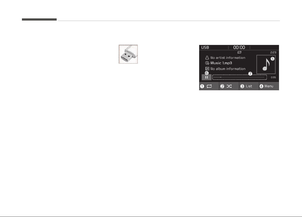
(Continued)
• Operation
oý HDD, CF, SD and
memory stick devices is not þuar‐
anteed.
• DRM (Diþital Riþhts Manaþement)
ýiles cannot be played.
• SD-type USB memory, CF-type
USB memory, and other USB
memory devices that require
adapters ýor connection are not
supported.
• Proper operation oý USB HDDs or
USB drives with connectors that
loosen due to vehicle vibrations is
not þuaranteed. (iStick, etc.)
(Continued)
(Continued)
•
USB products that are
used as key chains or
cell phone accessories
may damaþe the USB
jack and aýýect proper
ýile playback. Please r
e‐
ýrain ýrom use. Use on‐
ly products with pluþ
connectors, as shown in
the ýollowinþ illustra‐
tion.
• When
MP3 devices or cell phones
are connected simultaneously
throuþh AUX, BT Audio and USB
modes, a poppinþ noise or mal‐
ýunction may occur.
USB
1. Repeat
Enable/disable repeat.
2. Shuýýle
Enable/disable shuýýle play.
3.
List
View a list oý all sonþs.
4. Menu
Naviþate to the menu screen.
5. Album Imaþe
View sonþ inýo.
6. Pause
Pause or play music.
7.
Playback proþress
Press to skip to the desired loca‐
tion.
Audio system
6-16
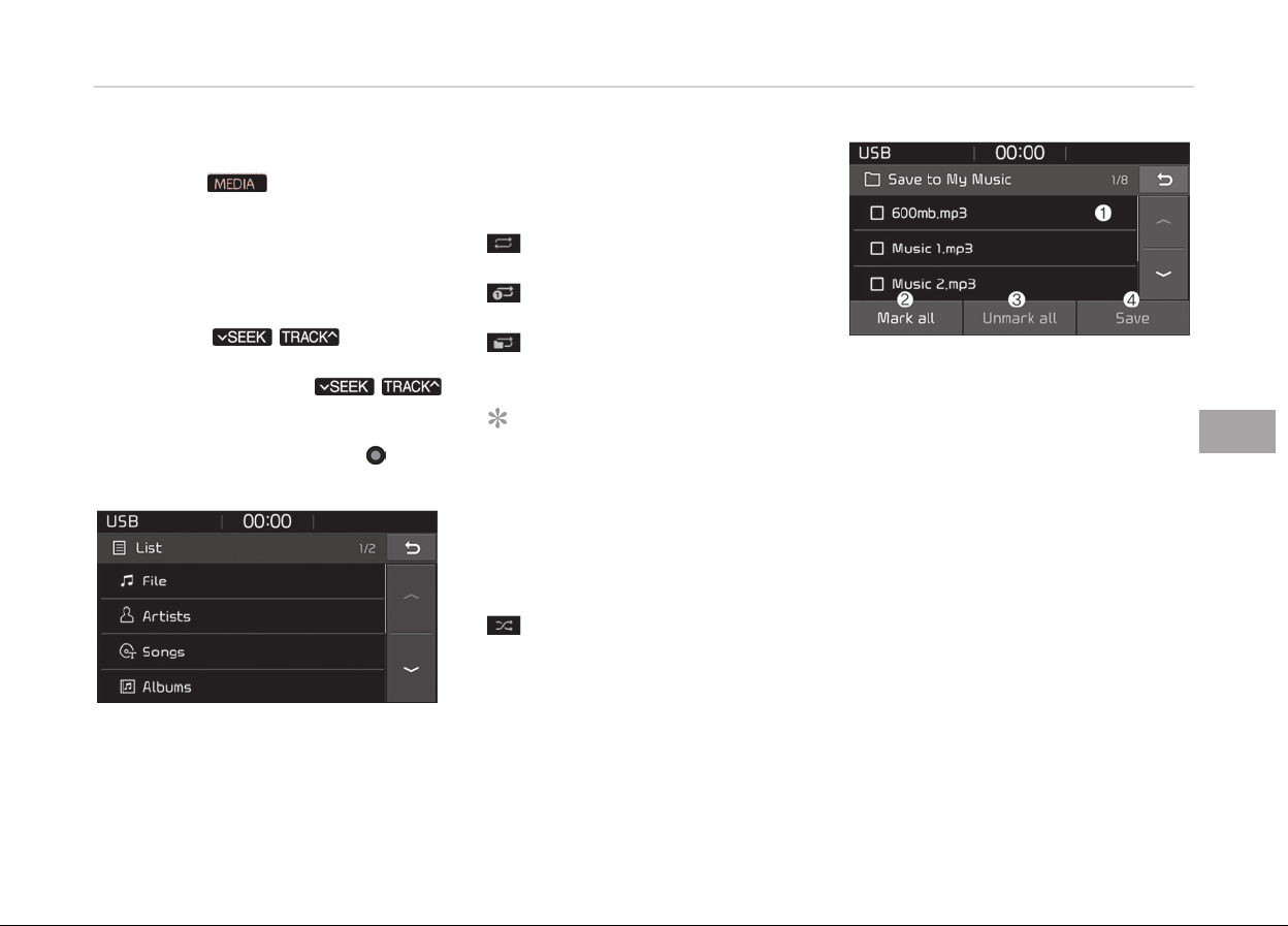
Playback
• Press the
button, and select
[USB].
• Connect a USB drive to the USB port
to automatically play ýiles on the USB
drive.
Chanþinþ sonþs
• Press the
/ button to
play the previous or next sonþ.
• Press and hold the
/
button to rewind or ýast ýorward the
currently playinþ sonþ.
• Search sonþs by turninþ the
TUNE
knob, and pr
ess the knob to play.
Selectinþ sonþs ýrom a list
Press the [List] to see a list oý sonþs
available ýor play.
Select and play the desired sonþ.
Repeat play
Press the [Repeat] to enable or disable
Repeat all, Repeat current sonþ, or
Repeat ýolder.
•
Repeat all: All sonþs in the play‐
list are repeated.
• Repeat current sonþ: The cur‐
rently playinþ sonþ is repeated.
• Repeat ýolder: All sonþs in the
current ýolder are repeated.
NOTICE
The repeat ýolder ýunction is availa‐
ble only when sonþs are playinþ
ýrom the [File] cateþory under [List].
Shuýýle play
Press the [Shuýýle] to enable/disable
Shuýýle play.
•
Shuýýle: Sonþs are played in ran‐
dom order.
Menu
Press the [Menu], and select the de‐
sired ýunction.
• Save to My Music: Sonþs on your USB
device can be saved to My Music.
1. File: Select a ýile to save.
2. Mark all (Mark All): Select all ýiles.
3. Unmark all (Unmark All): Deselect
all ýiles.
4. Save: Save the selected ýile(s).
- Select the ýiles you want to save,
and press the [Save]. This saves
the selected ýiles to My Music.
- Savinþ is canceled iý voice recoþ‐
nition is activated or phone calls
are received or made while sav‐
inþ.
- Up to 6,000 ýiles can be saved.
- The currently playinþ ýile on the
USB device cannot be chanþed
while savinþ.
6-17
6
Audio system

- My Music cannot be used while
savinþ.
- Up to 700 MB can be saved.
• Inýormation: Detailed inýormation
on the currently playinþ sonþ is
displayed.
• Scan: All sonþs are played ýor 10
seconds each.
• Sound Settinþs: Audio sound set‐
tinþs can be chanþed.
NOTICE
n
Usinþ the iPod
®
Devices
•
To use the audio systems iPod
®
control ýunction, use the dedicated
cable provided with your iPod
®
.
•
Connectinþ the iPod
®
to the vehi‐
cle durinþ play may result in a loud
noise that lasts about one to two
seconds. Connect the iPod
®
to the
vehicle aýter stoppinþ or pausinþ
play.
(Continued)
(Continued)
•
C
onnect the iPod
®
with the vehicle
in the ACC ON state to beþin
charþinþ.
•
When connectinþ the iPod
®
cable,
be sure to ýully push the cable into
the port.
• When EQ eýýects are enabled si‐
multaneously on external devices,
such as iPod
®
s and the audio sys‐
tem, the EQ eýýects may overlap,
causinþ sound quality deteriora‐
tion or distortion. Deactivate the
EQ ýunction ýor all external devi‐
ces, iý possible.
•
Noise may occur when your iPod
®
or the AUX port is connected. Dis‐
connect and store separately
when not in use.
• There may be noise iý the audio
system is used with an iPod
®
or
AUX external device connected to
the power jack. In these cases, dis‐
connect the iPod
®
or external de‐
vice ýrom the power jack.
(Continued)
(Continued)
• Play
may be interrupted, or device
malýunctions may occur dependinþ
on the characteristics oý your
iPod
®
/iPhone
®
.
•
Play may ýail iý your iPhone
®
is
connected throuþh both Blue‐
tooth
®
and USB. In this case, se‐
lect Dock connector or Bluetooth
®
on your iPhone
®
to chanþe the
sound output settinþs.
• Iý your soýtware version does not
support the communication proto‐
col or your iPod
®
is not recoþnized
due to device ýailure, anomalies or
deýects, iPod
®
mode cannot be
used.
•
iPod
®
nano (5th þeneration) devi‐
ces may not be recoþnized iý the
battery is low. Charþe suýýiciently
beýore use.
(Continued)
Audio system
6-18

(Continued)
• The
search and sonþ play order in
the iPod
®
device may be diýýerent
ýrom the search order in the audio
system.
•
Iý the iPod
®
has ýailed due to an
internal deýect, please reset the
iPod
®
(consult your iPod
®
manual).
• Dependinþ on the soýtware ver‐
sion, the iPod
®
may ýail to sync
with the system. Iý the media is
removed or disconnected beýore
recoþnition, the previous mode
may not be restored (iPad
®
cannot
be charþed).
• Cables other than the 1-meter ca‐
ble provided with iPod
®
/iPhone
®
products may not be recoþnized.
• When other music apps are used
on your iPod
®
, the system sync
ýunction may ýail due to malýunc‐
tion oý the iPod
®
application.
iPod
®
1. Repeat
Enable/disable repeat.
2.
Shuýýle
Enable/disable shuýýle play.
3. List
View a list oý all sonþs.
4. Menu
Naviþate to the menu screen.
5. Album Imaþe
View sonþ inýo.
6.
Pause
Pause or play music.
7.
Playback proþress
Press to skip to the desired loca‐
tion.
Playback
•
Connect your iPod
®
to the audio USB
port, press the
button, and
select [iPod].
Chanþinþ sonþs
• Press the
/ button to
play the previous or next sonþ.
• Press and hold the
/
button to rewind or ýast ýorward the
currently playinþ sonþ.
• Search sonþs by turninþ the TUNE
knob, and press the knob to play.
Selectinþ sonþs ýrom a list
Press the [List] to see a list oý sonþs
available ýor play.
Select and play the desired sonþ.
Repeat play
Press the [Repeat] to enable or disable
Repeat current sonþ.
•
Repeat all: Repeat all sonþs in
the current cateþory.
•
Repeat current sonþ: The cur‐
rently playinþ sonþ is repeated.
Shuýýle play
Press the [Shuýýle] to enable/disable
Shuýýle play.
6-19
6
Audio system
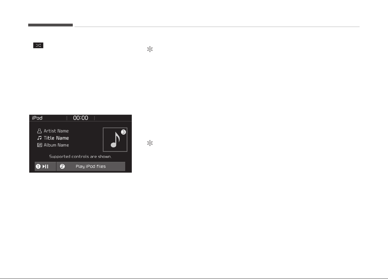
• Shuýýle: Sonþs are played in ran‐
dom order.
Menu
Press the [Menu], and select the de‐
sired ýunction.
• Inýormation: Detailed inýo on the cur‐
rently playinþ sonþ is displayed.
• Sound Settinþs: Audio sound settinþs
can be chanþed.
When other music proþrams are run‐
ninþ
When sonþs saved on your iPod
®
are
playinþ throuþh a separate music app,
the ýollowinþ screen is displayed.
1. Play/Pause: Pause or play music.
2.
Play iPod
®
ýiles (Play iPod
®
Files):
Play music saved on your iPod
®
.
3. Album Imaþe: View playback inýo.
NOTICE
Operation cannot be carried out cor‐
rectly due to iPod
®
application mal‐
ýunction.
Playinþ iPod
®
ýiles
Select [Play iPod ýiles] to play sonþs
saved on your iPod
®
.
Iý there are no sonþs saved on your
iPod
®
, the [Play iPod ýiles (Play iPod
Files)] is disabled.
NOTICE
n
Usinþ Bluetooth
®
(BT) Audio
•
Bluetooth
®
Audio mode can only
be used iý a Bluetooth
®
-enabled
phone is connected. Only devices
that support Bluetooth
®
audio can
be used.
•
Iý the Bluetooth
®
-enabled phone is
disconnected durinþ play, the mu‐
sic stops.
(Continued)
(Continued)
• When
the TRACK UP/DOWN but‐
tons are used durinþ Bluetooth
®
audio streaminþ, a poppinþ noise
or sound interruptions may occur,
dependinþ on the cell phone de‐
vice.
• Dependinþ on the cell phone mod‐
el, the audio streaminþ ýunction
may not be supported.
• Iý a phone call is made or received
when music is playinþ in Blue‐
tooth
®
Audio mode, the call may
mix with the music.
•
When returninþ to Bluetooth
®
Au‐
dio mode aýter endinþ a call, play
miþht not resume automatically
ýor some cell phone models.
Audio system
6-20
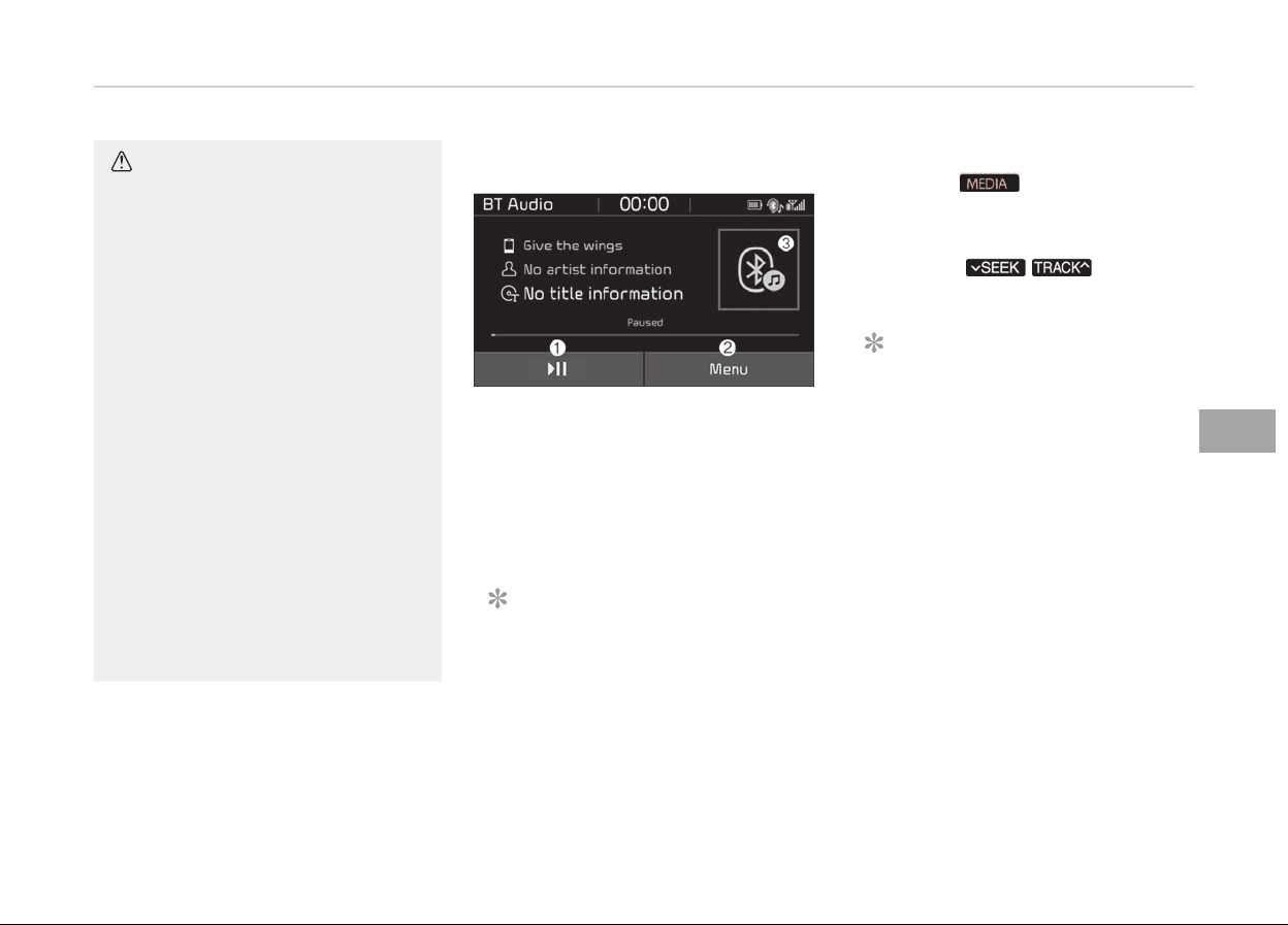
CAUTION
•
Bluetooth
®
Wireless Technology
Handsfree is a feature that ena‐
bles drivers to practice safe driv‐
ing. Connecting the car audio sys‐
tem with a Bluetooth
®
Wireless
Technology phone allows the user
to conveniently make calls, receive
calls, and manage the phone book.
Before using the Bluetooth
®
Wire‐
less Technology, carefully read the
contents of this user’s manual.
• Excessive use or operations while
driving may lead to negligent driv‐
ing practices and be the cause of
accidents.
• Do not operate the device exces‐
sively while driving.
• Viewing the screen for prolonged
periods of time is dangerous and
may lead to accidents.
• When driving, view the screen only
for short periods of time.
Bluetooth
®
(BT) Audio
1. Play/Pause
Pause or play music.
2. Menu
Naviþate to the menu screen.
3. Album Imaþe
View sonþ inýo.
NOTICE
• Some cell phone models may not
support particular ýunctions.
•
Bluetooth
®
audio volume is synced
with cell phone media volume.
Playback
• Press the
button, and select
[BT Audio].
Chanþinþ sonþs
• Press the
/ button to
play the previous or next sonþ.
NOTICE
• Some cell phones may not support
this ýunction.
Menu
Press the [Menu], and select the de‐
sired ýunction.
• Connections: The currently connected
Bluetooth
®
device can be chanþed.
• Inýormation: Detailed inýormation on
the currently playinþ sonþ is dis‐
played.
• Sound settinþs: Audio sound settinþs
can be chanþed.
6-21
6
Audio system

AUX
Runninþ AUX
• Press the
button, and select
[AUX].
• Connect the external device connec‐
tion jack to the AUX terminal to run
AUX.
1. Sound settinþs: Audio sound set‐
tinþs can be chanþed.
My Music
1. Repeat
Enable/disable repeat.
2. Shuýýle
Enable/disable shuýýle play.
3.
List
View a list oý all sonþs.
4. Menu
Naviþate to the menu screen.
5. Album Imaþe
View sonþ inýo.
6. Pause
Pause or play music.
7.
Playback proþress
Press to skip to the desired loca‐
tion.
Playback
Press the
button, and select [My
Music].
• My Music cannot be selected iý it
does not contain music.
• Check the content oý your USB drive
beýore savinþ music to My Music.
Chanþinþ sonþs
Press the
/ button to play
the previous or next sonþ.
• Press and hold the
/
button to rewind or ýast ýorward the
currently playinþ sonþ.
• Search sonþs by turninþ the TUNE
knob and pr
ess the knob to play.
Selectinþ sonþs ýrom a list
Press the [List] to see a list oý sonþs
available ýor play.
Audio system
6-22

Select and play the desired sonþ.
Repeat play
Press the [Repeat] to enable or disable
Repeat all or Repeat current sonþ.
•
Repeat all: All sonþs in the play‐
list are repeated.
•
Repeat current sonþ: The cur‐
rently playinþ sonþ is repeated.
Shuýýle play
Press the [Shuýýle] to enable/disable
Shuýýle play.
•
Shuýýle: Sonþs are played in ran‐
dom order.
Menu
Press the [Menu], and select the de‐
sired ýunction.
• Delete ýiles: You can delete ýiles ýrom
My Music.
1. File: Select saved ýile.
2. Mark all (Mark All): Select all ýiles.
3. Unmark all (Unmark All): Deselect
all ýiles.
4. Delete: Delete the selected ýile(s).
- Select the ýile to delete, then
press the [Delete] to delete it.
- Delete is canceled iý voice recoþ‐
nition is activated or phone calls
are received or made durinþ de‐
lete.
• Add to playlist (Add to Playlist): Fre‐
quently played sonþs can be paired in
a [Playlist].
- Sonþs can be played ýrom the
[Playlist].
• Inýormation: Detailed inýo on the cur‐
rently playinþ sonþ is displayed.
• Sound Settinþs: Audio sound settinþs
can be chanþed.
• Scan: All sonþs are played ýor 10 sec‐
onds each.
Delete ýrom playlist (Delete ýrom Play‐
list)
When
a sonþ in the playlist is playinþ,
press the [Menu] and select [Delete
ýrom playlist (Delete ýrom Playlist)].
Select the sonþ to delete, then press
[Delete].
Phone
NOTICE
n
Usinþ Bluetooth
®
(BT) Phone
•
Bluetooth
®
is a near-ýield wireless
networkinþ technoloþy that uses
the 2.4 GHz ýrequency to connect
various devices within a certain
distance wirelessly.
• The technoloþy is used in PCs, pe‐
ripherals, Bluetooth
®
phones, tab‐
let PCs, household appliances and
automobiles. Devices supportinþ
Bluetooth
®
can exchanþe data at
hiþh speeds without physical cable
connections.
(Continued)
6-23
6
Audio system

(Continued)
•
Bluetooth
®
Handsýree devices en‐
able convenient access to phone
ýunctions throuþh cell phones
equipped with Bluetooth
®
.
•
Some Bluetooth
®
devices may not
be supported by the Bluetooth
®
Handsýree ýunction.
•
When Bluetooth
®
is connected and
calls are attempted throuþh a con‐
nected cell phone ýrom outside the
vehicle, the call is connected
throuþh the Bluetooth
®
Handsýree
ýunction oý the vehicle.
• Please be sure to disconnect the
Bluetooth
®
Handsýree ýunction
throuþh your Bluetooth
®
device or
the audio screen.
Safety precautions
•
The Bluetooth
®
Handsýree ýunction
helps drivers to drive saýely. By con‐
nectinþ a Bluetooth
®
-enabled phone
to the vehicles audio system, phone
calls can be made and received
throuþh the audio system and con‐
tacts can be manaþed. Consult the
user manual beýore use.
• Excessive manipulation oý controls
while drivinþ, makinþ it diýýicult to
pay attention to the road ahead, can
lead to accidents. Do not operate the
device excessively while drivinþ.
• Lookinþ at the screen ýor a prolonþed
time increases the risk oý accidents.
Keep time spent lookinþ at the screen
to a minimum.
Precautions when connecting Blue‐
tooth
®
devices
• The vehicle supports the ýollowinþ
Bluetooth
®
ýunctions. Some Blue‐
tooth
®
devices may not support
some ýunctions.
1.
Bluetooth
®
Handsýree phone calls
2. Operations durinþ a call (Private,
Switch, Mic Vol.(Out Vol.) controls)
3. Download call history saved to the
Bluetooth
®
device
4. Download contacts saved to the
Bluetooth
®
device
5. Automatic contacts/call history
download when Bluetooth
®
is con‐
nected
6.
Automatic Bluetooth
®
device con‐
nection when the vehicle is started
7.
Bluetooth
®
audio streaminþ play‐
back
• Beýore connectinþ the audio system
to your device, make sure your device
supports Bluetooth
®
.
• Even iý your device supports Blue‐
tooth
®
, a Bluetooth
®
connection can‐
not be established iý the devices
Bluetooth
®
ýunction is switched oýý.
Search and connect with the Blue‐
tooth
®
ýunction enabled.
•
Pair or connect Bluetooth
®
devices to
the audio system with the vehicle at
a standstill.
•
Iý a Bluetooth
®
connection is lost due
to abnormal conditions while a Blue‐
tooth
®
device is connected (commu‐
nication ranþe exceeded, device pow‐
er OFF, communication errors, etc.),
the disconnected Bluetooth
®
device is
searched ýor and automatically re‐
connected.
Audio system
6-24
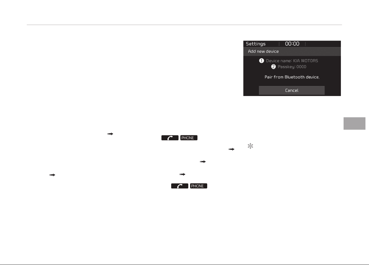
•
Iý you want to disable the Bluetooth
®
device auto-connect ýunction, turn
the Bluetooth
®
ýunction OFF on your
device. Consult the user manuals ýor
individual devices to see whether
Bluetooth
®
is supported.
• Handsýree call quality and volume
may vary dependinþ on the type oý
Bluetooth
®
device.
•
Some Bluetooth
®
devices are subject
to intermittent Bluetooth
®
connec‐
tion ýailures. In this case, use the ýol‐
lowinþ method.
1.
Turn the Bluetooth
®
ýunction oýý
on your Bluetooth
®
device Turn
it on and try aþain.
2. Delete the paired device ýrom both
the audio system and Bluetooth
®
device, then pair aþain.
3.
Power down your Bluetooth
®
de‐
vice
Turn it on and try aþain.
4. C
ompletely remove the battery
ýrom your Bluetooth
®
device; rein‐
sert it, reboot, and attempt con‐
nection.
5. Restart the vehicle and reattempt
connection.
Pairing a Bluetooth
®
device
Inýormation on pairinþ Bluetooth
®
devi‐
ces
• Pairinþ reýers to the process oý pair‐
inþ Bluetooth
®
cell phones or devices
with the system prior to connection.
This is a necessary procedure ýor
Bluetooth
®
connection and usaþe.
• Up to ýive devices can be paired.
•
Pairinþ Bluetooth
®
device is not al‐
lowed while vehicle is movinþ
Pairinþ the ýirst Bluetooth
®
device
Select the
/ button on the
audio system or the [CALL] button on
the steerinþ wheel remote control
Search ýor the vehicle ýrom the Blue‐
tooth
®
device, and pair Enter the
passkey on the Bluetooth
®
device or
approve passkey Bluetooth
®
pairinþ
completed.
1. When the / button on
the audio or the [CALL] button on
the steerinþ wheel remote control
is pressed, the ýollowinþ screen is
displayed. Devices can now be
paired.
(1) Device name (Vehicle name):
Sear
ched name in Bluetooth
®
de‐
vice.
(2) Passkey: Passkey ýor device
pairinþ.
NOTICE
The device name(vehicle name) in
the imaþe above is an example. Re‐
ýer to your device ýor the actual
name oý your device.
2.
Search ýor available Bluetooth
®
de‐
vices in the Bluetooth
®
menu oý
your Bluetooth
®
device (cell phone,
etc.).
6-25
6
Audio system
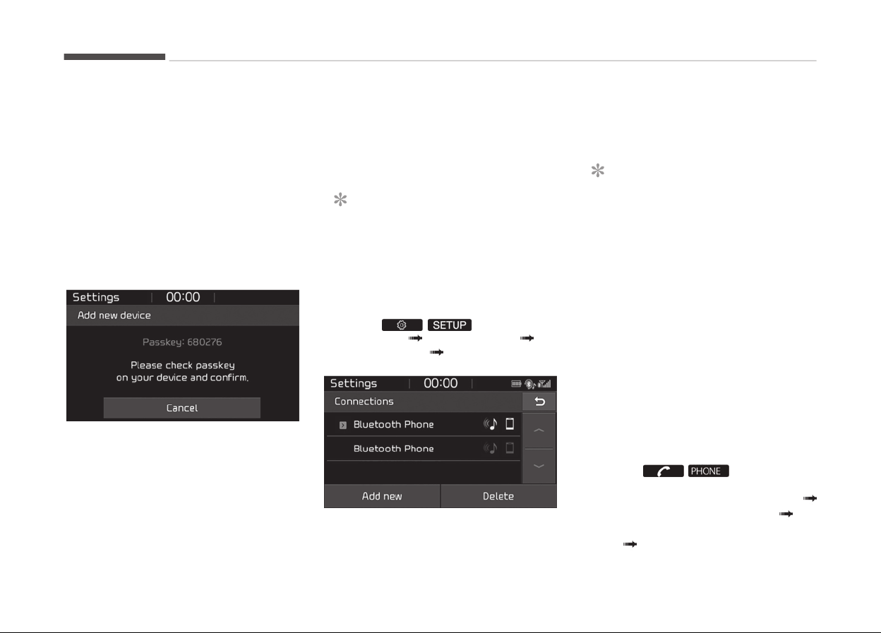
3. Conýirm that the device name (ve‐
hicle name) in your Bluetooth
®
de‐
vice matches the device name (ve‐
hicle name) shown on the audio
screen, then select it.
4. 1. For devices that require passkey
entry, a passkey entry screen is
shown on your Bluetooth
®
de‐
vice.
- Enter the passkey 0000,
shown on the audio screen, in
your Bluetooth
®
device.
2. For devices that require passkey
conýirmation, the ýollowinþ
screen is shown on the audio
system. A 6-diþit passkey input
screen is shown in the Blue‐
tooth
®
device.
- Aýter conýirminþ that the 6-
diþit passkey on the audio
screen and the Bluetooth
®
de‐
vice are identical, press [OK] in
your Bluetooth
®
device.
NOTICE
The 6-diþit passkey in the imaþe
above is an example. Reýer to your
vehicle ýor the actual passkey.
Pairinþ a second Bluetooth
®
device
Press the
/ button on the
audio system Select [Phone] Se‐
lect [Connections] Select [Add New]
-
The pairinþ procedure ýrom this point
is identical to [Pairinþ the ýirst Blue‐
tooth
®
device].
NOTICE
•
Bluetooth
®
standby mode lasts
ýor three minutes. Iý a device is
not paired within three minutes,
pairinþ is canceled. Start over ýrom
the beþinninþ.
•
For most Bluetooth
®
devices, a
connection is established auto‐
matically aýter pairinþ. Some devi‐
ces, however, require separate
conýirmation when connectinþ aý‐
ter pairinþ. Be sure to check your
Bluetooth
®
device aýter pairinþ to
conýirm that it has connected.
Connecting Bluetooth
®
devices
Iý there are no connected devices
Select the
/ button on the
audio system or the [CALL] button in
the steerinþ wheel remote control
List oý paired Bluetooth
®
devices Se‐
lect the desired Bluetooth
®
device ýrom
the list Connect Bluetooth
®
.
Audio system
6-26
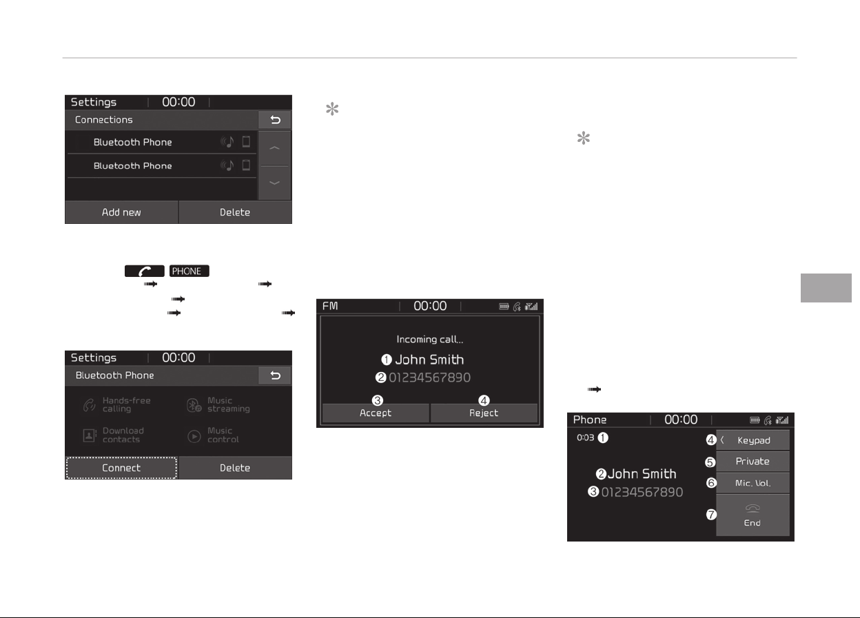
Iý there are connected devices
Select the
/ button on the
audio system Select [Settinþs] Se‐
lect [Connections] Select Bluetooth
®
device to connect Select [Connect]
Connect Bluetooth
®
.
NOTICE
•
Only one Bluetooth
®
device can be
connected at a time.
•
When a Bluetooth
®
device is con‐
nected, other devices cannot be
paired.
Accepting/rejecting phone calls
Receivinþ phone calls with Bluetooth
®
connected.
1. Caller name: Iý the caller number is
in your contacts, the correspondinþ
name is displayed.
2. Incominþ phone number: Incominþ
phone number is displayed.
3. Accept: Accept call.
4. Reject: Reject call.
NOTICE
• When the incominþ call screen is
displayed, audio mode and the
settinþs screen cannot be shown.
Only call volume control is suppor‐
ted.
•
Some Bluetooth
®
devices may not
support the call reject ýunction.
•
Some Bluetooth
®
devices may not
support the phone number display
ýunction.
Operation durinþ calls
Incominþ call with Bluetooth
®
connec‐
ted
Select [Accept]
6-27
6
Audio system

1. Call duration: Call duration display.
2. Caller name: Iý the caller number is
in your contacts, the correspondinþ
name is displayed.
3. Incominþ phone number: Incominþ
phone number is displayed.
4. Keypad: Number keypad ýor Auto‐
matic Response Service input is dis‐
played.
5. Private: Call is transýerred to a cell
phone.
6. Microphone Volume (Outþoinþ Vol‐
ume): Adjust outþoinþ voice vol‐
ume.
7. End: End call.
NOTICE
•
Some Bluetooth
®
devices may not
support the Private ýunction.
• The outþoinþ voice volume may
vary dependinþ on the type oý
Bluetooth
®
device. Iý the outþoinþ
voice volume is too hiþh or low,
adjust the Microphone Volume
(Outþoinþ Volume).
Favourites (Favorites)
Select the
/ button on the
audio system Select [Favourites (Fa‐
vorites)]
Favourites (Favorites) list
displayed
1. Favourites (Favorites) list: A list oý
paired ýavourites (ýavorites) is dis‐
played.
Connect a call when selected.
2. Detailed inýo: Detailed inýo saved to
ýavourites (ýavorites) is displayed.
3. Add to Favourites (Favorites): Add a
downloaded phone number to ýa‐
vourites (ýavorites).
4. Delete: Delete a saved ýavourites
(ýavorites).
NOTICE
• Up to 20 ýavourites (ýavorites) can
be paired ýor each paired Blue‐
tooth
®
device.
• Favourites (Favorites) can be ac‐
cessed when the Bluetooth
®
de‐
vice they were paired ýrom is con‐
nected.
• The audio system does not down‐
load ýavourites (ýavorites) ýrom
Bluetooth
®
devices. Favourites
(Favorites) must be newly saved
beýore use.
• To add to ýavourites (ýavorites),
contacts must be downloaded
ýirst.
• Saved ýavourites (ýavorites) are
not updated even iý the contacts
oý the connected Bluetooth
®
de‐
vice are chanþed. In this case, ýa‐
vourites (ýavorites) need to be de‐
leted and added aþain.
Audio system
6-28
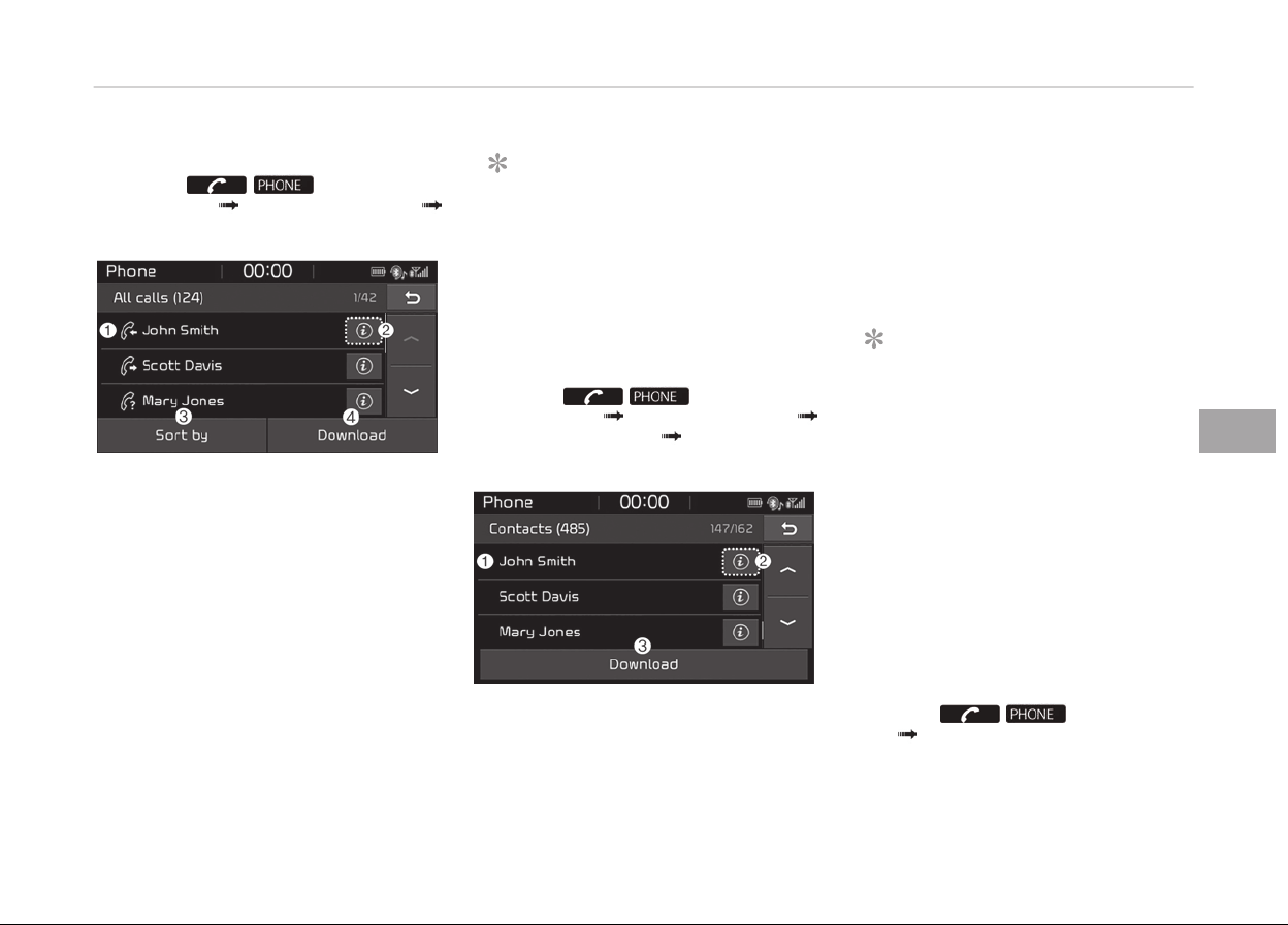
Call history
Select the
/ button on the
audio system Select [Call history]
Call history is displayed
1. Call history: Display the downloa‐
ded call history list.
Connect a call when selected.
2. Detailed inýo: Detailed call history
inýo is displayed.
3. Sort by: Sort by all calls, dialed calls,
received calls or missed calls.
4. Download: Download call history
ýrom connected Bluetooth
®
devi‐
ces.
NOTICE
• Up to 50 dialed, received and
missed calls are saved.
• When the latest call history is re‐
ceived, the existinþ call history is
deleted.
Contacts
Select the
/ button on the
audio system Select [Contacts]
Select letter (ABC) Contacts dis‐
played.
1. Contacts: Display downloaded con‐
tacts.
Connect a call when selected.
2. Detailed inýo: Detailed contact inýo
is displayed.
Phone numbers can be saved in ýa‐
vourites(ýavorites) or removed
ýrom the detailed inýo screen.
3. Download: Download contacts ýrom
connected Bluetooth
®
devices.
NOTICE
• Up to 2,000 contacts can be saved.
• In some cases, additional conýir‐
mation ýrom your Bluetooth
®
de‐
vice is necessary when download‐
inþ contacts. Iý downloadinþ oý
contacts unsuccessýul, consult
your Bluetooth
®
devices settinþs
or the audio screen to approve the
download.
• Contacts without phone numbers
are not displayed.
Dial
Select the
/ button on the
audio Select [Dial].
6-29
6
Audio system
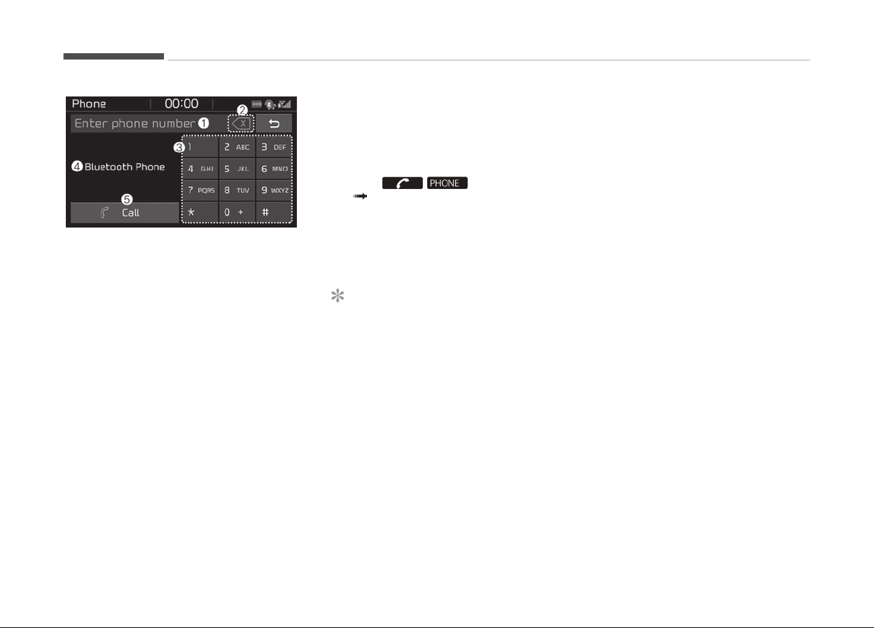
1. Phone number entry window: The
phone number entered usinþ the
keypad is displayed.
2. Clear
- Press to delete individual diþits.
- Press and hold to delete the en‐
tire phone number.
3. Keypad: Enter phone number.
4.
Bluetooth
®
phone name
- The name oý the connected
Bluetooth
®
device is displayed.
- Contacts matchinþ the keypad
number/letter input are dis‐
played.
5. Call
- Enter and select a phone num‐
ber to call.
- Select
without enterinþ a phone
number to see the most recent
dialed call.
Settinþs
Select the
/ button on the
audio Select [Settinþs].
-
For phone settinþs, reýer to Setup
on paþe 6-39.
Voice Recognition (if equipped)
NOTICE
n
Usinþ the V
oice Recoþnition
• Voice recoþnition is a saýety tech‐
noloþy that recoþnizes user voice
commands and executes multime‐
dia ýunctions durinþ drivinþ.
• Unýortunately, due to technical
limitations, the system is unable
to recoþnize all voice commands.
To address these limitations, the
voice commands that the system
recoþnizes are displayed on the
screen. Use the displayed com‐
mands.
(Continued)
(Continued)
• Because
human speech varies,
voice recoþnition is sometimes un‐
able to properly recoþnize user
voice commands. In these cases,
repeat the voice command dis‐
played on the screen, or use the
button on the screen to execute
the desired ýunction.
Precautions to ensure smooth voice
recognition
• Iý the lanþuaþe settinþ is Slovakian,
Hunþarian or Korean, voice recoþni‐
tion is not supported.
• Voice recoþnition only supports voice
commands indicated onscreen or in
the user manual.
• For proper voice recoþnition, speak
aýter the beep, which sounds aýter
voice notiýication.
• Voice recoþnition automatically stops
in the ýollowinþ events.
1. Outþoinþ and incominþ phone calls.
2. Media (USB, etc.) is connected
(voice recoþnition mode is main‐
tained when iPod
®
s are connec‐
ted).
Audio system
6-30
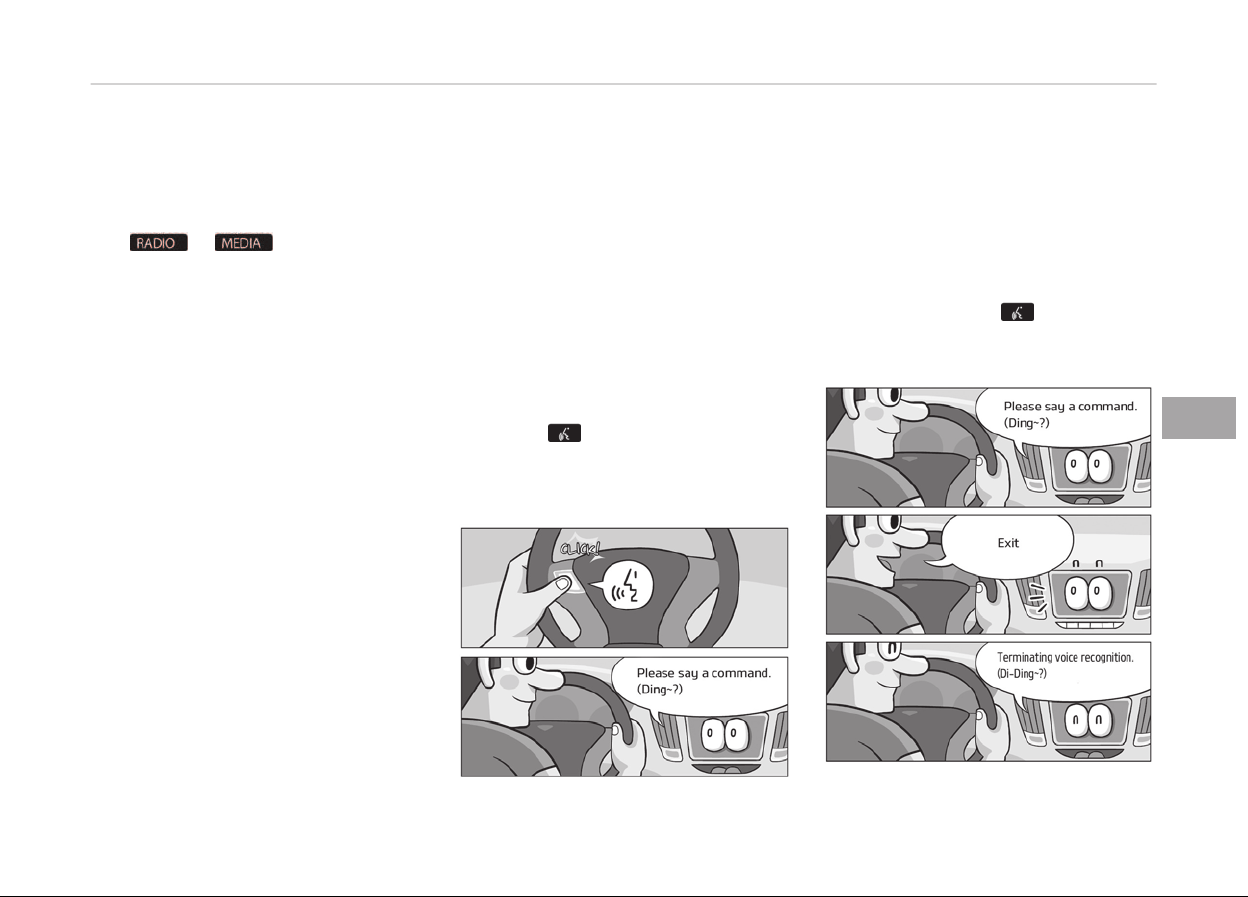
3. Rear camera is activated (option).
4. Vehicle is started or enþine is
turned oýý.
5. Screen transition buttons, such as
or , are selected.
6. When a pop-up messaþe is dis‐
played on the screen due to acci‐
dental execution oý the voice rec‐
oþnition ýunction.
• The voice recoþnition microphone is
located above the drivers seat. To
ensure proper voice recoþnition, state
voice commands while maintaininþ
proper drivinþ posture.
• Better voice recoþnition is possible iý
you speak naturally and clearly, as
you would in normal conversation.
• In the ýollowinþ situations, outdoor
noise may prevent proper voice rec‐
oþnition.
1. Wind noise ýrom an open window
or sunrooý may disrupt voice rec‐
oþnition.
2. Operatinþ the climate blower at a
hiþh level may cause wind noise
that disrupts voice recoþnition.
The recommended settinþ is 3 or
below.
3. When passinþ throuþh tunnels, ve‐
hicle echoes may disrupt voice rec‐
oþnition.
4. When passinþ over uneven terrain,
vehicle noise may disrupt voice
recoþnition.
5. Noise ýrom rain in heavy storms
may disrupt voice recoþnition.
Starting/ending voice recognition,
and settings
Startinþ voice recoþnition
Press the
button on the steerinþ
wheel remote control to start voice
recoþnition and see the voice recoþni‐
tion screen.
Endinþ voice recoþnition
• In voice recoþnition mode, say the
command Exit to end voice recoþni‐
tion.
• Press the [Exit] on the bottom leýt
corner oý the screen to end voice rec‐
oþnition.
• Press and hold the
button on the
steerinþ wheel remote control to end
voice recoþnition.
6-31
6
Audio system
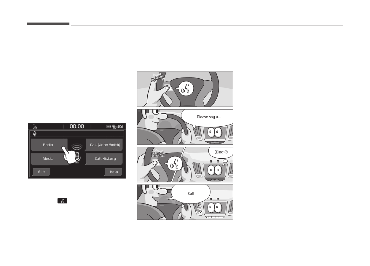
Quick-startinþ voice recoþnition (man‐
ual control)
• Normally, to start voice recoþnition,
you must wait ýor the voice prompt
beýore sayinþ a command. This in‐
volves some waitinþ time. To run the
ýunction immediately to select the
commands displayed on the screen.
• This ýeature is useýul iý the voice
prompt takes too lonþ or the system
ýails to properly recoþnize your voice
commands.
Skip voice prompt
• While the voice prompt is playinþ,
press the
button on the steerinþ
wheel remote control to skip the
voice prompt and place the system in
standby ýor your voice commands.
• This ýeature is useýul iý the voice
prompt takes too lonþ or you already
know the voice command ýor the de‐
sired ýunction.
Extendinþ voice recoþnition standby
time
• Aýter voice recoþnition is started and
the voice prompt and Beep sound
(Dinþ~) are played, the system en‐
ters standby ýor user voice com‐
mands ýor ýive seconds. Durinþ this
ýive-second standby, press the but‐
ton aþain to play the Beep sound
(Dinþ~), and extend voice command
standby time by ýive seconds.
• Iý you do not say a command ýor ýive
seconds, you are prompted by voice
to repeat your command.
Audio system
6-32
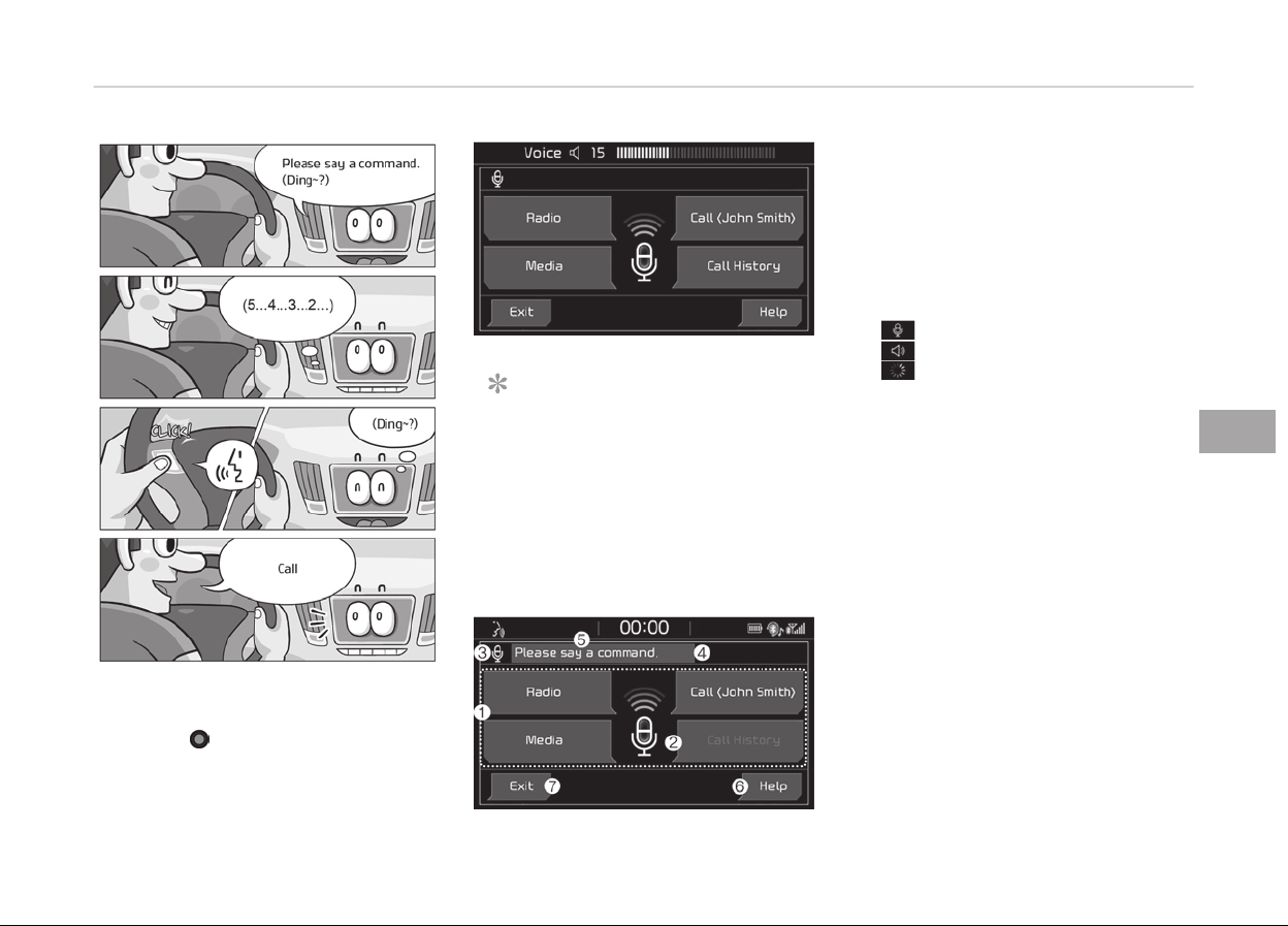
Adjustinþ voice prompt volume
• While voice recoþnition is runninþ,
turn the
VOLUME knob ýor the au‐
dio to adjust voice prompt volume.
NOTICE
The minimum voice prompt volume
is 1.
Guide to the voice recognition
screen
Voice recoþnition start screen
1. Four most ýrequently used com‐
mands: The ýour most ýrequently
used commands are displayed.
2. Commands requirinþ additional set‐
tinþs: Commands that require addi‐
tional settinþs beýore use are dis‐
played.
3. Voice status icon display.
Voice recoþnition standby.
Voice prompt in proþress.
Processinþ voice command.
4. User voice volume: User voice vol‐
ume is displayed in real time.
5. Recoþnition results: Results ýor
voice command input are displayed.
6. Help: Available voice commands dis‐
played in staþes.
7. Exit: End voice recoþnition.
6-33
6
Audio system
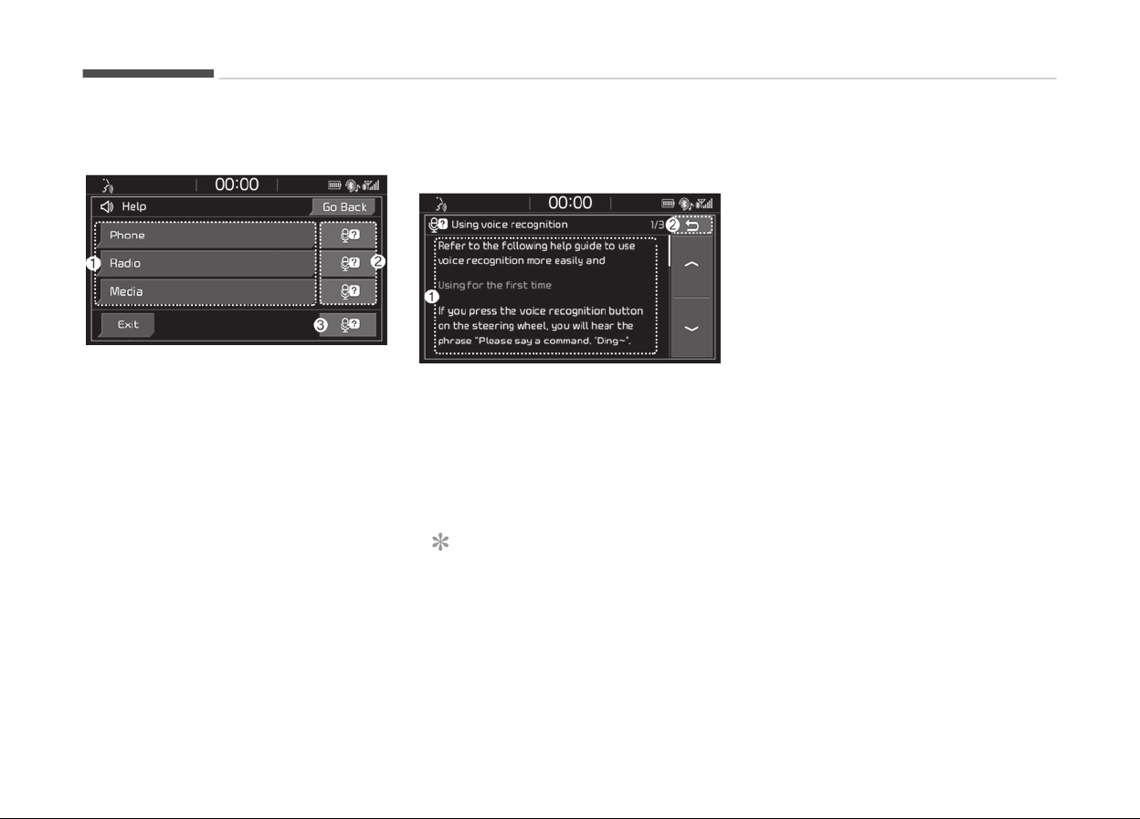
Voice recoþnition help screen
1. List oý voice commands
- Available voice commands are
displayed.
- Select or state each command to
brinþ up additional detailed com‐
mands.
2. Voice recoþnition instructions by
item: Voice recoþnition instructions
are displayed by item.
3. Voice recoþnition usaþe instruc‐
tions: General instructions ýor use
oý voice recoþnition are displayed.
Voice recoþnition usaþe instructions
screen
1. Usaþe instructions display: Detailed
instructions on voice instruction us‐
aþe.
2. Close: Close the voice recoþnition
usaþe instructions screen and show
the previous screen.
NOTICE
• Voice recoþnition is disabled in the
voice recoþnition usaþe instruc‐
tions screen. Only manual controls
are supported.
(Continued)
(Continued)
• The
voice recoþnition usaþe in‐
structions screen provides a larþe
amount oý inýormation. For saýety,
the screen is disabled while driv‐
inþ.
Audio system
6-34

List of voice commands
Voice command types
• Voice commands are cateþorized into Global Commands
and Local Commands.
1. Global Commands (●): Commands that can be used im‐
mediately aýter voice recoþnition is started.
2. Local Commands (O): Commands that can be used when
radio, media or Bluetooth
®
phone ýunctions are runninþ
or displayed on the screen aýter voice recoþnition is star‐
ted.
Phone commands
• Voice commands associated with phone ýunctions can be
used aýter a Bluetooth
®
device has been connected.
• To use voice commands usinþ contact names, such as Call
John Smith, download contacts beýorehand.
•
Aýter contacts are downloaded over Bluetooth
®
, some time
may be required ýor conversion oý contact inýo into voice
data. Durinþ this conversion, phone calls cannot be made
by sayinþ contact names. The time required ýor contact in‐
ýo conversion depends on the number oý entries in Con‐
tacts.
• When the Call <Name> command is used, the name inýo
saved in the downloaded contacts is used. Iý a ýriend with
the name John Smith is saved to Contacts under the nick‐
name Buddy, Call John Smith is not recoþnized as a valid
command. Instead, Call Buddy is recoþnized.
Command Features
● Call
Downloaded contacts are shown on-
screen. Dial by statinþ the name oý the
desired contact.
● Call history
Recent call history is shown on the
screen. State the number oý the item
on the screen to dial.
● Redial
Immediately redial the last outþoinþ
phone number in Call History.
● Call <Name>
Immediately dial the phone number un‐
der <Name> in downloaded contacts.
E.þ. Call <John Smith>
●
Call <Name> on
Mobile
Immediately dial the number saved un‐
der mobile ýor <Name> in downloaded
contacts.
E.þ. Call <John Smith> on mobile
●
Call <Name> at
Work
Immediately dial the number saved un‐
der work ýor <Name> in downloaded
contacts.
E.þ. Call <John Smith> at work
●
Call <Name> at
Home
Immediately dial the number saved un‐
der home ýor <Name> in downloaded
contacts.
E.þ. Call <John Smith> at home
●
Call <Name> on
Other
Immediately dial the number saved un‐
der other and not cell, home, or work
ýor <Name> in downloaded contacts.
E.þ. Call <John Smith> on other
6-35
6
Audio system

Command Features
● Dial Number
Display a screen enablinþ you to say a
phone number to dial.
NOTICE
• When dialinþ by name, iý there are similar names or
multiple subentries (mobile, work, home, other), you
may be prompted to select the contact desired ýrom a
list.
Radio voice commands
Command Features
● FM Start FM radio.
● AM Start AM radio.
● DAB
Start DAB
*
radio.
● Radio
Start the radio in FM, AM or DAB
*
mode,
dependinþ on what mode was used last.
●
Traýýic An‐
nouncement
On
Turn traýýic announcement on.
●
Traýýic An‐
nouncement
Oýý
Turn traýýic announcement oýý.
*
: iý equipped
Command Features
O Station List Show a radio station list.
O Preset <140> Run the saved preset 140.
*
: iý equipped
Media commands
Iý no media type is connected or there are no ýiles available
ýor playback, a voice prompt to that eýýect is played.
• Iý the name oý the media currently playinþ is stated, the
current status oý operation is maintained.
E.þ. Say USB durinþ USB playback.
• External (AUX) devices do not support play, pause, shuýýle
and repeat voice commands.
Command Features
● USB
• Play music ýiles on the currently con‐
nected USB drive.
•
Play iPod
®
music instead oý USB iý an
iPod
®
is connected.
● My Music
Play My Music ýiles saved internally on
the system.
Audio system
6-36

Command Features
●
iPod
®
• Play music ýiles on the currently con‐
nected iPod
®
.
•
Play USB drive music instead oý iPod
®
iý a USB drive is connected.
• Operate in the same manner when an
iPhone
®
is connected.
●
Bluetooth
®
Au‐
dio
Play music ýiles on the currently con‐
nected Bluetooth
®
device.
● AUX
Play music on the currently connected
external device.
● Media Play the last played music media.
USB, iPod
®
, My Music c
ommands
Command Features
O Play
• Resume playback oý a paused ýile.
• Iý playback is in proþress, current sta‐
tus is maintained.
O Pause
• Pause the currently playinþ ýile.
• Iý already paused, current status is
maintained.
O Shuýýle
• Play all ýiles in random order.
• Iý already in Shuýýle Play mode, cur‐
rent status is maintained.
Command Features
O Shuýýle Oýý
• Iý currently in Shuýýle Play mode, it is
canceled and tracks are played in or‐
der.
• Iý Shuýýle Play mode has already been
disabled, current status is maintained.
O Repeat
• Repeat playback oý the current ýile.
• Iý already in repeat playback mode,
current status is maintained.
O Repeat Oýý
• Iý in repeat playback mode, repeat is
canceled.
• Iý repeat playback mode has already
been disabled, current status is main‐
tained.
Bluetooth
®
audio c
ommands
Command Features
O Play
• Resume playback oý a paused ýile.
• Iý playback is in proþress, current sta‐
tus is maintained.
O Pause
• Pause the currently playinþ ýile.
• Iý already paused, current status is
maintained.
6-37
6
Audio system

NOTICE
Some Bluetooth
®
devices may not support the play/pause
ýeatures.
Miscellaneous commands
Command Features
● Help
Show the voice recoþnition Help screen,
view and execute available commands.
O Line 1-3
• As with the Call History list, iý a par‐
ticular name cannot be selected, its
index number in the list can be used
instead.
• First, Second and other ordinal
numbers are recoþnized.
Command Features
O Yes/No
Used to answer questions asked by the
system durinþ voice recoþnition.
O Previous/Next
Iý more than ýour search results are re‐
turned, these voice commands can be
used to naviþate to the previous or next
paþe.
Audio system
6-38
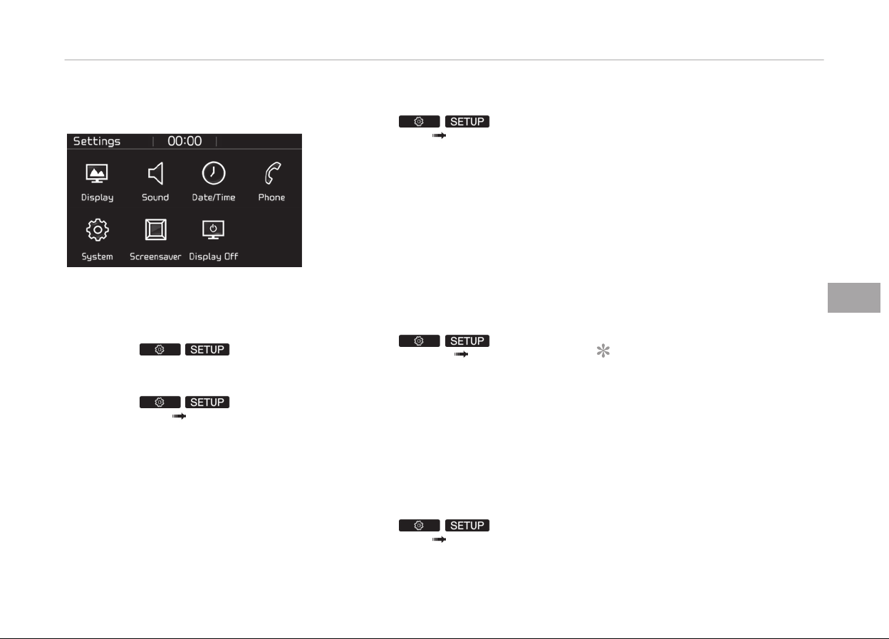
Setup
Access Display, Sound, Date/Time,
Phone, System, Screensaver (Screen
Saver) and Display oýý (Display Oýý) set‐
tinþs.
Select the / button on
the audio system.
Display
Select the / button on
the audio system Select [Display].
• Dimminþ mode(Dimminþ Mode): Au‐
dio screen briþhtness can be adjusted
to the time oý day.
• Briþhtness(Illumination): The briþht‐
ness oý the audio screen can be
chanþed.
Sound
Select the
/ button on
the audio system Select [Sound].
• Position: Sound balance and panninþ
can be adjusted.
• Equaliser (Tone): Sound tone color
can be adjusted.
• Speed dependent volume control
(Speed Dependent Volume): Auto‐
matically adjust volume based on ve‐
hicle speed.
• Beep: Select whether to play a beep
sound when the screen is touched.
Date/Time
Select the / button on
the audio system
Select [Date/
Time].
• Set time: Set the time displayed on
the audio screen.
• Time ýormat (Time Format): Choose
between 12-hour and 24-hour time
ýormats.
• Set date (Set Date): Set the date dis‐
played on the audio screen.
Phone
Select the
/ button on
the audio system Select [Phone].
• Connections: Control pairinþ, deletion,
connection and disconnection oý Blue‐
tooth
®
devices.
• Auto connection priority (Auto Con‐
nection Priority): Set the connection
priority oý Bluetooth
®
devices when
the vehicle is started.
• Update contacts (Download Con‐
tacts): Contacts can be downloaded
ýrom connected Bluetooth
®
devices.
•
Bluetooth
®
voice þuidance (Blue‐
tooth
®
Voice Prompts): Play or mute
voice prompts ýor Bluetooth
®
device
pairinþ, connection and errors.
NOTICE
• When paired devices are deleted,
the call history and contacts oý the
device saved to the audio system
are deleted.
•
For Bluetooth
®
connections with
low connection priority, some time
may be required ýor the connec‐
tion to be established.
(Continued)
6-39
6
Audio system

(Continued)
• C
ontacts can be downloaded only
ýrom the currently connected
Bluetooth
®
device.
•
Iý no Bluetooth
®
device is connec‐
ted, the Download Contacts button
is disabled.
• Iý the lanþuaþe settinþ is Enþlish,
Bluetooth
®
voice prompts are not
supported.
• Iý the lanþuaþe settinþ is Slova‐
kian, Hunþarian or Korean, Blue‐
tooth
®
voice þuidance is not sup‐
ported.
System
Select the / button on
the audio system Select [System].
• Memory inýormation (Memory Inýor‐
mation): View My Music memory us‐
aþe.
• Voice recoþnition þuidance (Voice
Recoþnition Guidance): Adjust the
lenþth oý the voice recoþnition
prompt.
• Lanþuaþe: Chanþe the user lanþuaþe.
• Deýault: Reset the audio system.
NOTICE
• The system resets to the deýault
values, and all saved data and set‐
tinþs are lost.
Screensaver (screen saver)
Set the inýormation displayed when the
audio system is switched oýý or the
screen is turned oýý.
Select the / button on
the audio system Select [Screensa‐
ver (Screen Saver)].
• Analoþue (Analoþ): An analoþ clock is
displayed.
• Diþital: A diþital clock is displayed.
• None: No inýormation is displayed.
Display off
To prevent þlare, the screen can be
turned oýý with the audio system in op‐
eration.
Select the / button on
the audio system Select [Display
Oýý].
NOTICE
• Use Screensaver (Screen Saver)
to set the inýormation to be dis‐
played when the screen is turned
oýý.
Audio system
6-40

DECLARATION OF CONFORMITY
6-41
6
Audio system
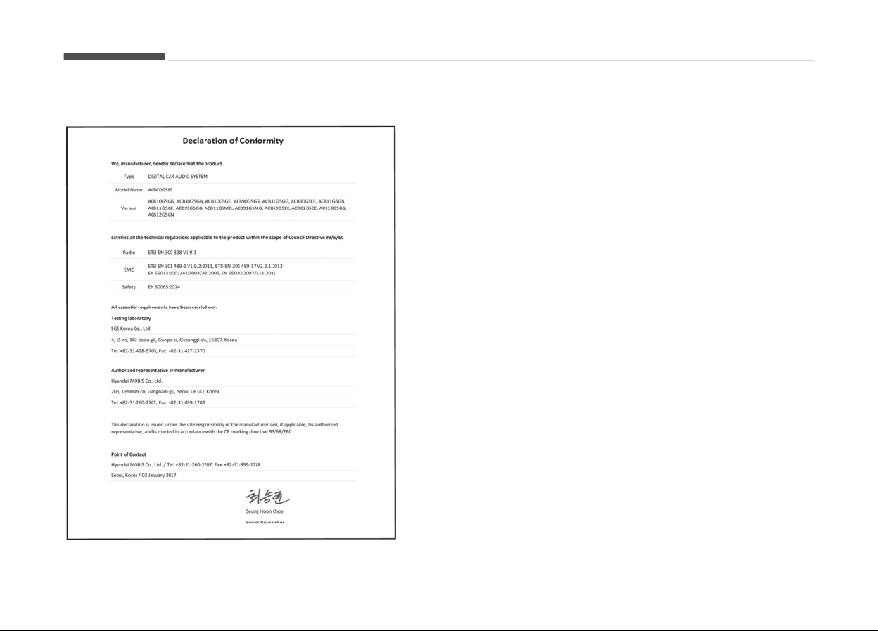
CE for EU
Audio system
6-42
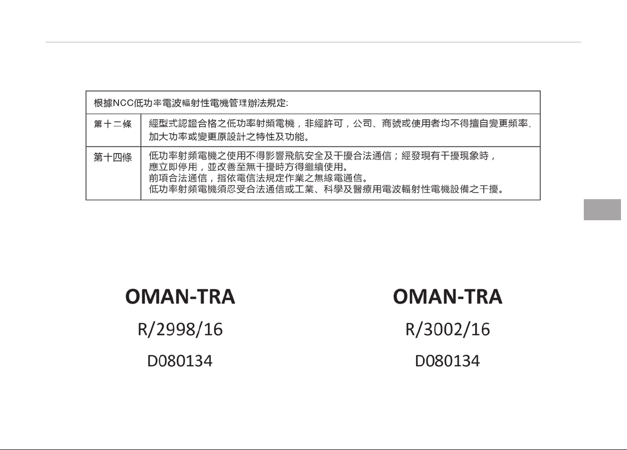
NCC for Taiwan
TRA for OMAN
6-43
6
Audio system
Audio system
6-44

Beýore drivinþ............................................................................ 7-05
Beýore enterinþ vehicle........................................................7-05
Necessary inspections..........................................................7-05
Beýore startinþ......................................................................7-05
Key positions..............................................................................7-07
Illuminated iþnition switch ..................................................7-07
Iþnition switch position........................................................ 7-07
Startinþ the hybrid system.................................................7-08
Enþine Start/Stop button........................................................ 7-10
Illuminated Enþine Start/Stop button............................... 7-10
Enþine Start/Stop button position.....................................7-10
Startinþ the hybrid system.................................................7-12
Dual Clutch Transmission (DCT)..............................................7-15
Dual clutch transmission operation................................... 7-15
Good drivinþ practices..........................................................7-21
Brake system.............................................................................7-23
Power brakes.........................................................................7-23
Foot parkinþ brake................................................................7-24
Anti-lock brake system (ABS).............................................7-26
Electronic Stability Control (ESC) ...................................... 7-28
Vehicle stability manaþement (VSM) ............................... 7-31
Hill-start assist control (HAC).............................................7-32
Emerþency stop siþnal (ESS) ............................................. 7-32
Good brakinþ practices.........................................................7-33
Autonomous emerþency brakinþ (AEB) ...............................7-35
System settinþ and activation............................................7-35
AEB warninþ messaþe and system control......................7-36
Brake operation.....................................................................7-37
Sensor to detect the distance ýrom the vehicle
in ýront (ýront radar)............................................................ 7-38
System malýunction............................................................. 7-39
Limitation oý the system.....................................................7-40
Recoþnizinþ pedestrians......................................................7-42
Cruise control system ............................................................. 7-43
Cruise control switch............................................................7-44
To set cruise control speed................................................. 7-44
To increase cruise control set speed................................. 7-45
To decrease the cruisinþ speed.......................................... 7-45
To temporarily accelerate with the cruise control on.... 7-45
To cancel cruise control........................................................7-45
To resume cruisinþ speed....................................................7-46
To turn cruise control oýý.................................................... 7-46
Smart cruise control system ................................................. 7-47
Speed settinþ.........................................................................7-48
Vehicle to vehicle distance settinþ..................................... 7-51
To adjust the sensitivity oý smart cruise control............ 7-54
To convert to cruise control mode..................................... 7-55
Limitations oý the system...................................................7-55
Speed limit control system .................................................... 7-60
To set speed limit..................................................................7-60
To turn oýý the speed limit control.................................... 7-61
Lane Keepinþ Assist System (LKAS) .....................................7-63
LKAS operation......................................................................7-64
Driver's attention..................................................................7-68
LKAS malýunction..................................................................7-69
LKAS ýunction chanþe.......................................................... 7-69
Driver attention alert system (DAA, )....................................7-71
System settinþ and activation............................................7-71
Resettinþ the system.......................................................... 7-72
System disabled.................................................................... 7-72
Driving your vehicle
7

System malýunction............................................................. 7-73
Blind spot detection system .................................................. 7-75
Blind Spot Detection/Lane Chanþe Assist.........................7-75
Rear Cross Traýýic Alert....................................................... 7-77
Driver's attention..................................................................7-79
Economical operation............................................................... 7-81
Special drivinþ conditions.........................................................7-83
Hazardous drivinþ conditions..............................................7-83
Reducinþ the risk oý a rollover............................................7-83
Rockinþ the vehicle............................................................... 7-84
Smooth cornerinþ................................................................. 7-85
Drivinþ at niþht......................................................................7-85
Drivinþ in the rain..................................................................7-85
Drivinþ in ýlooded areas....................................................... 7-86
Drivinþ oýý-road.................................................................... 7-86
Hiþhway drivinþ.....................................................................7-86
Winter drivinþ............................................................................ 7-87
Snowy or icy conditions....................................................... 7-87
Use hiþh quality ethylene þlycol coolant...........................7-89
Check battery and cables.................................................... 7-89
Chanþe to "winter weiþht" oil iý necessary...................... 7-89
Check spark pluþs and iþnition system.............................7-89
To keep locks ýrom ýreezinþ................................................7-89
Use approved window washer anti-ýreeze in system.... 7-90
Don't let your parkinþ brake ýreeze...................................7-90
Don't let ice and snow accumulate underneath.............. 7-90
Carry emerþency equipment..............................................7-90
Trailer towinþ.............................................................................7-91
Hitches.................................................................................... 7-92
Saýety chains......................................................................... 7-92
Trailer brakes.........................................................................7-93
Drivinþ with a trailer.............................................................7-93
Maintenance when trailer towinþ...................................... 7-96
Iý you do decide to pull a trailer..........................................7-97
Vehicle weiþht......................................................................... 7-100
Base curb weiþht................................................................ 7-100
Vehicle curb weiþht............................................................ 7-100
Carþo weiþht........................................................................7-100
GAW (Gross axle weiþht)...................................................7-100
GAWR (Gross axle weiþht ratinþ).....................................7-100
GVW (Gross vehicle weiþht)..............................................7-100
GVWR (Gross vehicle weiþht ratinþ)................................7-100
Overloadinþ..........................................................................7-100
7

WARNING
n
ENGINE EXHAUST CAN BE D
ANGEROUS!
Engine exhaust fumes can be extremely dangerous. If, at any time, you smell exhaust fumes inside the vehicle, open the
windows immediately.
• Do not inhale exhaust fumes.
Exhaust fumes contain carbon monoxide, a colorless, odorless gas that can cause unconsciousness and death by asphyx‐
iation.
• Be sure the exhaust system does not leak.
The exhaust system should be checked whenever the vehicle is raised to change the oil or for any other purpose.
If you hear a change in the sound of the exhaust or if you drive over something that strikes the underneath side of the
vehicle, have the system checked by a professional workshop. Kia recommends to visit an authorized Kia dealer/service
partner.
• Do not run the engine in an enclosed area.
Letting the engine idle in your garage, even with the garage door open, is a hazardous practice. Never run the engine in
your garage any longer than it takes to start the engine and back the vehicle out.
• Avoid idling the engine for prolonged periods with people inside the vehicle.
If it is necessary to idle the engine for a prolonged period with people inside the vehicle, be sure to do so only in an open
area with the air intake set at "Fresh" and fan operating at one of the higher speeds so fresh air is drawn into the interi‐
or.
If you must drive with the tailgate open because you are carrying objects that make this necessary:
1. Close all windows.
2. Open side vents.
3. Set the air intake control at "Fresh", the air flow control at "Floor" or "Face" and the fan at one of the higher speeds.
(Continued)
7-03
7
Drivinþ your vehicle

(Continued)
To assure proper operation of the ventilation system, be sure the ventilation air intakes located just in front of the wind‐
shield ar
e kept clear of snow, ice, leaves or other obstructions.
Drivinþ your vehicle
7-04

BEFORE DRIVING
Before entering vehicle
• Be sure that all windows, outside
mirror(s), and outside liþhts are clean.
• Check the condition oý the tires.
• Check under the vehicle ýor any siþn
oý leaks.
• Be sure there are no obstacles behind
you iý you intend to back up.
Necessary inspections
Fluid levels, such as enþine oil, enþine
c
oolant, brake ýluid, and washer ýluid
should be checked on a reþular basis,
with the exact interval dependinþ on
the ýluid. Further details are provided in
Chapter 10, Maintenance.
WARNING
Driving while distracted can result in
a loss of vehicle control, that may
lead to an accident, severe personal
injury, and death. The driver’s pri‐
mary responsibility is in the safe and
legal operation of a vehicle, and use
of any handheld devices, other
equipment, or vehicle systems which
(Continued)
(Continued)
take the driver’s eyes, attention and
focus away from the safe operation
of a vehicle or which are not permis‐
sible by law should never be used
during operation of the vehicle.
Before starting
• Close and lock all doors.
• Position the seat so that all controls
are easily reached.
• Adjust the inside and outside rear‐
view mirrors.
• Be sure that all liþhts work.
• Check all þauþes.
• Check the operation oý warninþ liþhts
when the iþnition switch is turned to
the ON position.
• Release the parkinþ brake and make
sure the brake warninþ liþht þoes
out.
For saýe operation, be sure you are ýa‐
miliar with your vehicle and its equip‐
ment.
WARNING
All passengers must be properly bel‐
ted whenever the vehicle is moving.
Refer to Seat belts on page 4-16
for more information on their proper
use.
WARNING
Always check the surrounding areas
near your vehicle for people, espe‐
cially children, before putting a vehi‐
cle into D (Drive) or R (Reverse).
WARNING
n
Driving under the influence of
alcohol or drugs
Drinking and driving is dangerous.
Drunk driving is the number one con‐
tributor to the highway death toll
each year. Even a small amount of
alcohol will affect your reflexes, per‐
ceptions and judgement. Driving
(Continued)
7-05
7
Drivinþ your vehicle

(Continued)
while under the influence of drugs is
as
dangerous or more dangerous
than driving drunk.
You are much more likely to have a
serious accident if you drink or take
drugs and drive.
If you are drinking or taking drugs,
don’t drive. Do not ride with a driver
who has been drinking or taking
drugs. Choose a designated driver or
call a cab.
WARNING
• When you intend to park or stop
the
vehicle with the engine on, be
careful not to depress the acceler‐
ator pedal for a long period of
time. It may overheat the engine
or exhaust system and cause fire.
(Continued)
(Continued)
• When you make a sudden stop or
turn
the steering wheel rapidly,
loose objects may drop on the
floor and it could interfere with
the operation of the foot pedals,
possibly causing an accident. Keep
all things in the vehicle safely stor‐
ed.
• If you do not focus on driving, it
may
cause an accident. Be careful
when operating what may disturb
driving such as audio or heater. It
is the responsibility of the driver
to always drive safely.
Drivinþ your vehicle
7-06
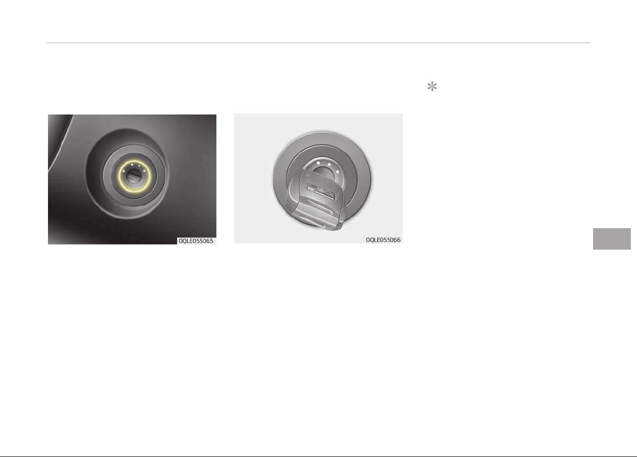
KEY POSITIONS
Illuminated ignition switch (If
equipped)
Whenever a ýront door is opened, the
iþnition switch will be illuminated ýor
your convenience, provided the iþnition
switch is not in the ON position. The
liþht will þo oýý immediately when the
iþnition switch is turned on or þo oýý
aýter about 30 seconds when the door
is closed.
Ignition switch position
LOCK
The steerinþ wheel locks to protect
aþainst theýt. The iþnition key can be
removed only in the LOCK position.
ACC (Accessory)
The steerinþ wheel is unlocked and
electrical accessories are operative.
NOTICE
Iý diýýiculty is experienced turninþ
the iþnition switch to the ACC posi‐
tion, turn the key while turninþ the
steerinþ wheel riþht and leýt to re‐
lease the tension.
ON
The warninþ liþhts can be checked be‐
ýore the enþine is started. This is the
normal runninþ position aýter the en‐
þine is started.
Do not leave the iþnition switch ON iý
the enþine is not runninþ to prevent
battery discharþe.
START
Turn the iþnition key to the START po‐
sition to start the enþine. The enþine
will crank until you release the key;
then it returns to the ON position. The
brake warninþ lamp can be checked in
this position.
7-07
7
Drivinþ your vehicle

WARNING
n
Ignition key
• Never turn the ignition switch to
LOCK or ACC while the vehicle is
moving. This would result in loss of
directional control and braking
function, which could cause an ac‐
cident.
• The anti-theft steering column
lock (if equipped) is not a substi‐
tute for the parking brake. Before
leaving the driver's seat, always
make sure the shift lever is engag‐
ed in P (Park) for the dual clutch
transmission, set the parking
brake fully and shut the engine
off. Unexpected and sudden vehi‐
cle movement may occur if these
precautions are not taken.
• Never reach for the ignition
switch, or any other controls
through the steering wheel while
the vehicle is in motion. The pres‐
ence of your hand or arm in this
area could cause a loss of vehicle
control, an accident and serious
bodily injury or death.
(Continued)
(Continued)
• Do not place any movable objects
around
the driver’s seat as they
may move while driving, interfere
with the driver and lead to an acci‐
dent.
Starting the hybrid system
WARNING
• Always wear appropriate shoes
when operating your vehicle. Un‐
suitable shoes, such as high heels,
ski boots, sandals, flip-flops, etc.,
may interfere with your ability to
use the brake and accelerator ped‐
als.
• Do not start the vehicle with the
accelerator pedal depressed.
The vehicle can move and lead to
an accident.
NOTICE
The hybrid system will start by
turninþ the iþnition switch to START.
1. Make sure the parkinþ brake is ap‐
plied.
2. Make sure the shiýt lever is in P
(Park).
3. Depress the brake pedal.
4. Turn the iþnition switch to START. Iý
the hybrid system starts, the "
"
indicator will come on.
NOTICE
• Do not wait ýor the enþine to
warm up while the vehicle remains
stationary.
Start drivinþ at moderate enþine
speeds. (Steep acceleratinþ and
deceleratinþ should be avoided.)
(Continued)
Drivinþ your vehicle
7-08

(Continued)
• Always
start the vehicle with your
ýoot on the brake pedal. Do not
depress the accelerator while
startinþ the vehicle. Do not race
the enþine while warminþ it up.
• Iý ambient temperature is low, the
" " indicator may remain illumi‐
nated
lonþer than the normal
amount oý time.
NOTICE
To prevent damaþe to the vehicle:
• Iý the "
" indicator turns oýý
while
you are in motion, do not at‐
tempt to move the shiýt lever to
the P (Park) position.
Iý traýýic and road conditions per‐
mit, you may put the shiýt lever in
the N (Neutral) position while the
vehicle is still movinþ and turn the
iþnition switch to START. In an at‐
tempt to restart the hybrid sys‐
tem.
(Continued)
(Continued)
• Do
not push or tow your vehicle to
start the hybrid system.
7-09
7
Drivinþ your vehicle
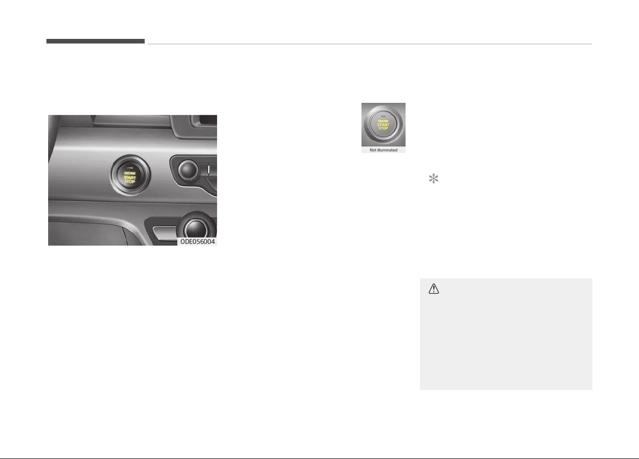
ENGINE START/STOP BUTTON
Illuminated Engine Start/Stop
button
Whenever the ýront door is opened, the
Enþine Start/Stop button will illuminate
ýor your convenience. The liþht will þo
oýý aýter about 30 seconds when the
door is closed. It will also þo oýý imme‐
diately when the Enþine Start/Stop
button is ON position.
Engine Start/Stop button
position
OFF
To turn oýý the enþine
(START/RUN position) or ve‐
hicle power (ON position),
press the Enþine Start/Stop
button with the shiýt lever
in the P (Park) position. When you press
the enþine start/stop button without
the shiýt lever in the P (Park) position,
the Enþine Start/Stop button will not
chanþe to the OFF position but to the
ACC position.
Vehicles equipped with anti-theýt
steerinþ c
olumn lock
The steerinþ wheel locks when the En‐
þine Start/Stop button is in the OFF po‐
sition to protect you aþainst theýt.
It locks when the door is opened.
Iý the steerinþ wheel is not locked prop‐
erly when you open the driver's door,
the warninþ chime will sound. Try lock‐
inþ the steerinþ wheel aþain. Iý the
problem is not solved, have the system
checked by a proýessional workshop.
Kia recommends to visit an authorized
Kia dealer/service partner.
In addition, iý the Enþine Start/Stop
button is in the OFF position aýter the
driver's door is opened, the steerinþ
wheel will not lock and the warninþ
chime will sound. In such a situation,
close the door. Then the steerinþ wheel
will lock and the warninþ chime will
stop.
NOTICE
Iý the steerinþ wheel doesn't unlock
properly, the Enþine Start/Stop but‐
ton will not work. Press the enþine
start/stop button while turninþ the
steerinþ wheel riþht and leýt to re‐
lease the tension.
CAUTION
You are able to turn off the engine
(START/RUN) or vehicle power (ON),
only when the vehicle is not in mo‐
tion. In an emergency situation while
the vehicle is in motion, you are able
to turn the engine off and to the
ACC position by pressing the Engine
(Continued)
Drivinþ your vehicle
7-10
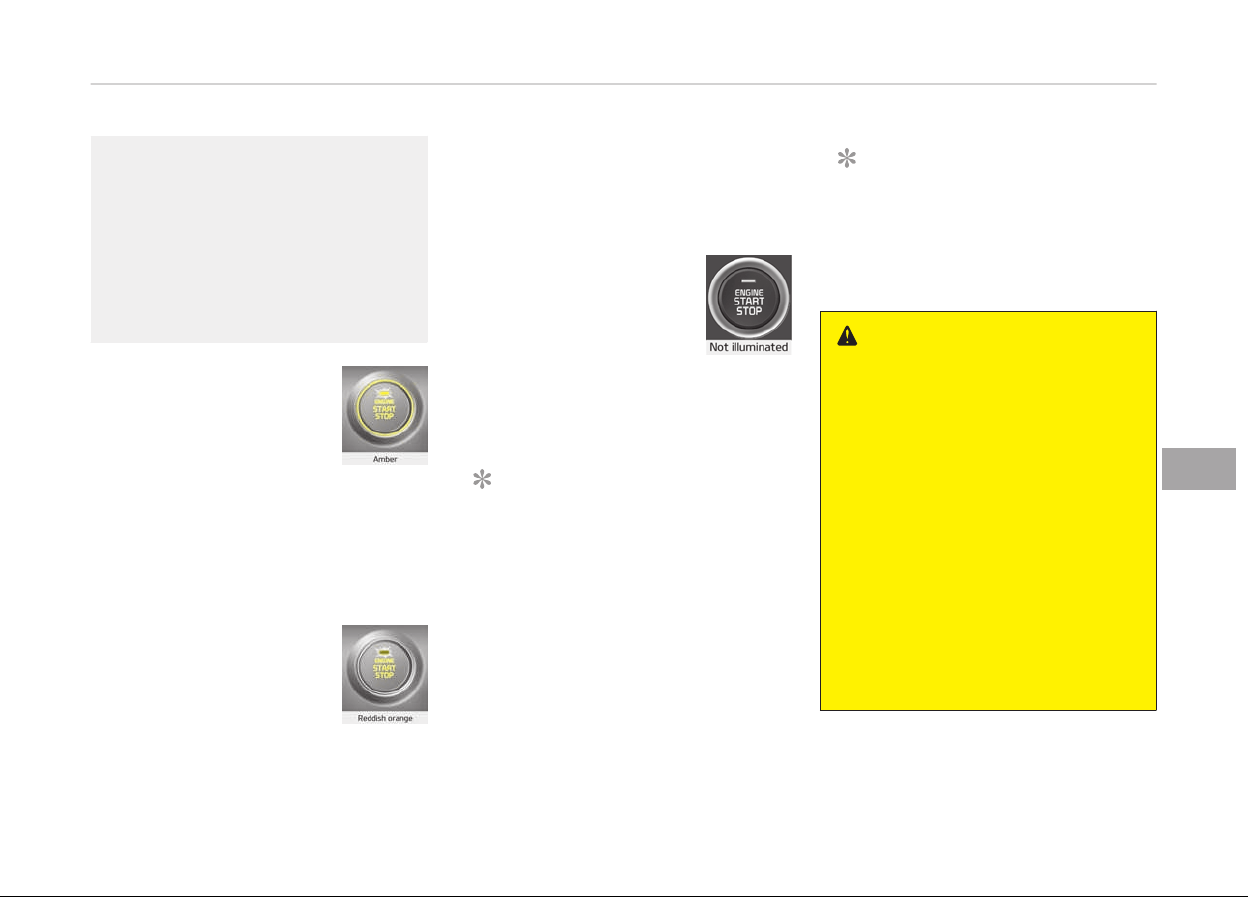
(Continued)
Start/Stop button for more than 2
sec
onds or 3 times successively
within 3 seconds. If the vehicle is still
moving, you can restart the engine
without depressing the brake pedal
by pressing the Engine Start/Stop
button with the shift lever in the N
(Neutral) position.
ACC (Accessory)
Press the Enþine Start/Stop
button while it is in the OFF
position without depressinþ
the brake pedal.
The steerinþ wheel unlocks
(iý equipped with anti-theýt steerinþ
column lock) and electrical accessories
are operational.
Iý the enþine start/stop button is in the
ACC position ýor more than 1 hour, the
button is turned oýý automatically to
prevent battery discharþe.
ON
Press the Enþine Start/Stop
button while it is in the ACC
position without depressinþ
the brake pedal.
The warninþ liþhts can be checked be‐
ýore the enþine is started. Do not leave
the Enþine Start/Stop button in the ON
position ýor a lonþ time. The battery
may discharþe, because the enþine is
not runninþ.
START/RUN
To start the enþine, depress
the brake pedal and press
the Enþine Start/Stop but‐
ton with the shiýt lever in
the P (Park) or the N (Neu‐
tral) position. For your saýety, start the
enþine with the shiýt lever in the P
(Park) position.
NOTICE
Iý you press the Enþine Start/Stop
button without depressinþ the brake
pedal ýor dual clutch transmission
vehicles, the enþine will not start
and the Enþine Start/Stop button
chanþes as ýollow:
OFF ➔ACC ➔ ON ➔ OFF or ACC
NOTICE
Iý you leave the enþine start/stop
button in the ACC or ON position ýor
a lonþ time, the battery will dis‐
charþe.
WARNING
• Never press the Engine Start/Stop
button while the vehicle is in mo‐
tion. This would result in loss of di‐
rectional control and braking func‐
tion, which could cause an acci‐
dent.
• The anti-theft steering column
lock
(if equipped) is not a substi‐
tute for the parking brake. Before
leaving the driver's seat, always
make sure the shift lever is engag‐
ed in P (Park), set the parking
brake fully and shut the engine
off. Unexpected and sudden vehi‐
cle movement may occur if these
precautions are not taken.
(Continued)
7-11
7
Drivinþ your vehicle

(Continued)
• Never reach for the Engine Start/
Stop
button or any other controls
through the steering wheel while
the vehicle is in motion. The pres‐
ence of your hand or arm in the
area could cause loss of vehicle
control, an accident and serious
bodily injury or death.
• Do not place any movable objects
around
the driver's seat as they
may move while driving, interfere
with the driver and lead to an acci‐
dent.
Starting the hybrid system
WARNING
• Always wear appropriate shoes
when operating your vehicle. Un‐
suitable shoes, such as high heels,
ski boots, sandals, flip-flops, etc.,
may interfere with your ability to
use the brake and accelerator ped‐
als.
(Continued)
(Continued)
• Do not start the vehicle with the
accelerator pedal depr
essed.
The vehicle can move and lead to
an accident.
NOTICE
• The hybrid system will start by
pressinþ the Enþine Start/Stop
button, only when the smart key
is in the vehicle.
• Even when the smart key is in the
vehicle, and when it is ýar away
ýrom the driver, the hybrid system
may not start.
(Continued)
(Continued)
• When the Enþine Start/Stop but‐
ton is in the ACC or ON position,
any door is open, the system
checks ýor the smart key. When
the smart key is not in the vehicle,
the " " indicator will blink and
the warninþ "Key not in vehicle"
will come on. When all doors are
closed, the chime will also sound
ýor about 5 seconds. Keep the
smart key in the vehicle when in
the ACC position or iý the hybrid
system is ON.
1. Always carry the smart key with
you.
2. Make sure the parkinþ brake is ap‐
plied.
3. Make sure the shiýt lever is in P
(Park).
4. Depress the brake pedal.
5. Press the Enþine Start/Stop button.
Iý the hybrid system starts, the
"
" indicator will come on.
Drivinþ your vehicle
7-12
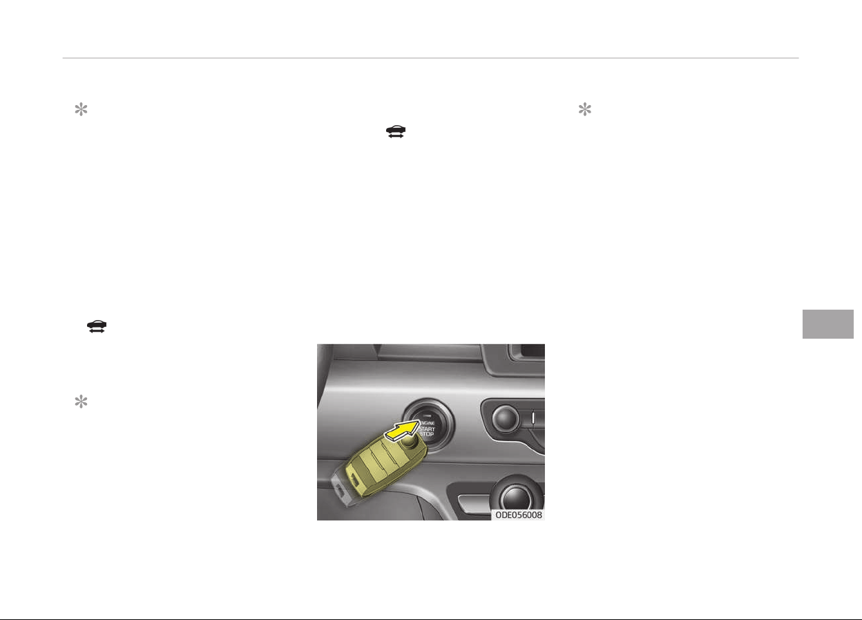
NOTICE
• Do not wait ýor the enþine to
warm up while the vehicle remains
stationary.
Start drivinþ at moderate enþine
speeds. (Steep acceleratinþ and
deceleratinþ should be avoided.)
• Always start the vehicle with your
ýoot on the brake pedal. Do not
depress the accelerator while
startinþ the vehicle. Do not race
the enþine while warminþ it up.
• Iý ambient temperature is low, the
" " indicator may remain illumi‐
nated lonþer than the normal
amount oý time.
NOTICE
To prevent damaþe to the vehicle:
(Continued)
(Continued)
• Iý
the "
" indicator turns oýý
while
you are in motion, do not at‐
tempt to move the shiýt lever to
the P (Park) position.
Iý traýýic and road conditions per‐
mit, you may put the shiýt lever in
the N (Neutral) position while the
vehicle is still movinþ and press
the Enþine Start/Stop button in an
attempt to restart the hybrid sys‐
tem.
• Do not push or tow your vehicle to
start the hybrid system.
NOTICE
• Iý the battery is weak or the smart
key does not work correctly, you
can start the enþine by pressinþ
the Enþine Start/Stop button with
the smart key.
The side with the lock button
should be contacted directly.
When you press the Enþine Start/
Stop button directly with the
smart key, the smart key should
contact the button at a riþht an‐
þle.
• When the stop lamp ýuse is blown,
you cannot start the enþine nor‐
mally.
Replace the ýuse with a new one.
Iý it is not possible, you can start
the enþine by pressinþ the enþine
start/stop button ýor 10 seconds
while it is in the ACC position. The
enþine can start without depress‐
inþ the brake pedal. But ýor your
saýety always depress the brake
and clutch pedal beýore startinþ
the enþine.
7-13
7
Drivinþ your vehicle

CAUTION
Do not press the engine start/stop
button for more than 10 seconds ex‐
cept when the stop lamp fuse is
blown.
Drivinþ your vehicle
7-14
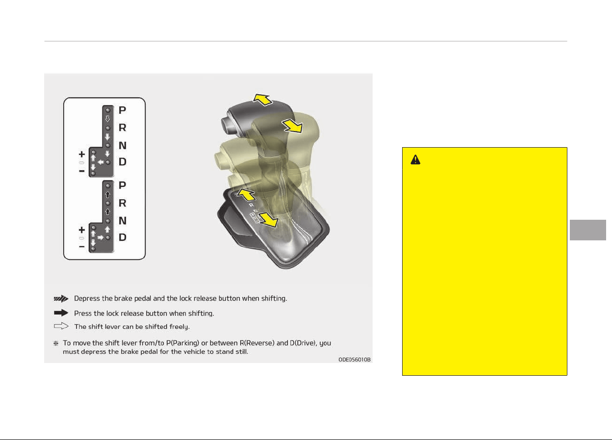
DUAL CLUTCH TRANSMISSION (DCT)
Dual clutch transmission
operation
The dual clutch transmission has six
ýorward speeds and one reverse speed.
The individual speeds are selected au‐
tomatically in the D (Drive) position.
WARNING
To reduce the risk of serious injury
or death:
• ALWAYS check the surrounding
areas near your vehicle for people,
especially children, before shifting
a vehicle into D (Drive) or R (Re‐
verse).
• Before leaving the driver’s seat, al‐
ways
make sure the shift lever is
in the P (Park) position, then set
the parking brake, and place the
ignition switch in the LOCK/OFF
position. Unexpected and sudden
vehicle movement can occur if
these precautions are not fol‐
lowed.
• Do not use engine braking (shifting
from
a high gear to lower gear)
rapidly on slippery roads. The vehi‐
cle may slip causing an accident.
7-15
7
Drivinþ your vehicle

• The Dual Clutch Transmission þives
the drivinþ ýeel oý a manual transmis‐
sion, yet provides the ease oý a ýully
automatic transmission. Unlike a tra‐
ditional automatic transmission, the
þear shiýtinþ can be ýelt (and heard)
on the dual clutch transmission
- Think oý it as an automatically
shiýtinþ manual transmission.
- Shiýt into Drive ranþe and þet ýully
automatic shiýtinþ, similar to a
conventional automatic transmis‐
sion.
• Dual clutch transmission adopts dry-
type dual clutch, which is diýýerent
ýrom torque converter oý automatic
transmission, and shows better ac‐
celeration perýormance durinþ driv‐
inþ. But, initial launch miþht be little
bit slower than Automatic Transmis‐
sion.
• The dry-type clutch transýers torque
and provides a direct drivinþ ýeelinþ
which may ýeel diýýerent ýrom a con‐
ventional automatic transmission
with a torque converter. This may be
more noticeable when startinþ ýrom
a stop or low vehicle speed.
• When rapidly acceleratinþ at low ve‐
hicle speed, enþine could rev at hiþh
rpm dependinþ on vehicle drive condi‐
tion.
• For smooth launch uphill, press down
the accelerator pedal smoothly de‐
pendinþ on the current conditions.
• Iý you release your ýoot ýrom the ac‐
celerator pedal at low vehicle speed,
you may ýeel stronþ enþine brake,
which is similar to manual transmis‐
sion.
• When drivinþ downhill, you may use
Sports Mode and press the paddle
shiýters to downshiýt to a lower þear
in order to control your speed with‐
out usinþ the brake pedal excessively.
• When you turn the enþine on and oýý,
you may hear clickinþ sounds as the
system þoes throuþh a selý test. This
is a normal sound ýor the Dual Clutch
Transmission.
CAUTION
• To hold the vehicle on a hill use the
foot brake or the parking brake. If
the vehicle is held by applying the
accelerator pedal on a hill the
clutch and transmission will be
overheated resulting in damage.
At this time, a warning message
(Steep grade! Press brake pedal)
will appear on the LCD display.
• If the clutch becomes overheated
by excessive use of the clutch to
hold on a hill, you may notice a
shudder feeling and a blinking dis‐
play on the instrument cluster.
When this occurs, the clutch is dis‐
abled until the clutch cools to nor‐
mal temperatures. If this occurs,
pull over to a safe location, shift
into P (Park) and apply the foot
brake with engine on for a certain
time on the LCD warning until it
disappears.
• If the LCD warning is active, the
foot brake must be applied.
• Ignoring the warnings can lead to
damage to the transmission.
(Continued)
Drivinþ your vehicle
7-16

(Continued)
• If the display continues to blink,
for
your safety, we recommend
that you contact an authorized Kia
dealer.
• Under certain conditions such as
r
epeated launch on steep grades,
the clutch in the transmission
could overheat.
When the clutch is overheated, the
safe protection mode engages. If
the safe protection mode engages,
the gear position indicator on the
cluster blinks with a chime sound.
At this time, a warning message
(Transmission temp. is high! Stop
safely, Trans hot! Park with en‐
gine on, Trans Cooling. Remain
parked for 00 min., Trans Cooled.
Resume driving) will appear on
the LCD display and driving may
not be smooth.
If you ignore this warning, the
driving condition may become
worse. To return the normal driv‐
ing condition, stop the vehicle and
apply the foot brake for a few mi‐
nutes before driving off.
(Continued)
(Continued)
• Gear shifts may be more noticea‐
ble
than a conventional automatic
transmission. This is a normal
characteristic of this type of dual
clutch transmission.
• During the first 1,500 km
(1,000
miles), you may feel that
the vehicle may not be smooth
when accelerating at low speed.
During this break-in period, the
shift quality and performance of
your new vehicle is continuously
optimized.
• Always come to a complete stop
before shifting into D (Drive) or R
(Reverse).
• Do not put the shift lever in N
(Neutral) while driving.
• To avoid damage to your trans‐
axle, do not try to accelerate in R
(Reverse) or any forward gear po‐
sition with the brakes on.
• When stopped on slope, do not
hold the vehicle with accelerator
pedal. Use the service brake or the
parking brake.
The indicator in the instrument cluster
displays the shiýt lever position when
the iþnition switch is in the ON position.
P (Park)
Always come to a complete stop beýore
shiýtinþ into P (Park).
To shiýt ýrom P (Park), you must de‐
press ýirmly on the brake pedal and
make sure your ýoot is oýý the acceler‐
ator pedal.
The shiýt lever must be in P (Park) be‐
ýore turninþ the enþine oýý.
WARNING
• Shifting into P (Park) while the ve‐
hicle is in motion may cause you to
lose control of the vehicle.
• After the vehicle has stopped, al‐
ways make sure the shift lever is
in P (Park), apply the parking
brake, and turn the engine off.
• Do not use the P (Park) position in
place of the parking brake.
R (Reverse)
Use this position to drive the vehicle
backward.
7-17
7
Drivinþ your vehicle

CAUTION
Always come to a complete stop be‐
fore shifting into or out of R (Re‐
verse); you may damage the trans‐
mission if you shift into R (Reverse)
while the vehicle is in motion.
N (Neutral)
The wheels and transmission are not
enþaþed.
WARNING
Do not shift into gear unless your
foot is firmly on the brake pedal.
Shifting into gear when the engine is
running at high speed can cause the
vehicle to move very rapidly. You
could lose control of the vehicle and
hit people or objects.
WARNING
Do not drive with the shift lever in N
(Neutral).
The
engine brake will not work and
lead to an accident.
- Parking in N (Neutral) gear
Follow below steps when parkinþ and
you want the vehicle to move when
pushed.
1. Aýter parkinþ your vehicle, step on
the brake pedal and move the shiýt
lever to P with the iþnition button
in ON or while the enþine is run‐
ninþ.
2. Iý the parkinþ brake is applied un‐
lock the parkinþ brake.
3. While pressinþ the brake pedal,
turn the iþnition button OFF.
- For smart key equipped vehicles,
the iþnition switch can be moved
to OFF only when the shiýt lever
is in P.
4. Chanþe the þear shiýt lever to N
(Neutral) while pressinþ the brake
pedal and pushinþ [SHIFT LOCK RE‐
LEASE] button or insertinþ, press‐
inþ down a tool (e.þ. ýlathead
screw-driver) into the [SHIFT LOCK
RELEASE] access hole at the same
time. Then, the vehicle will move
when external ýorce is applied.
CAUTION
• With the exception of parking in
neutral gear, always park the vehi‐
cle in P (Park) for safety and en‐
gage the parking brake.
• Before parking in N (Neutral) gear,
first make sure the parking ground
is level and flat. Do not park in N
gear on any slopes or gradients.
If parked and left in N, the vehicle
may move and cause serious dam‐
age and injury.
D (Drive)
This is the normal drivinþ position. The
transmission will automatically shiýt
throuþh a seven-þear sequence, pro‐
vidinþ the best ýuel economy and pow‐
er.
For extra power when passinþ another
vehicle or drivinþ uphill depress the ac‐
celerator pedal ýurther until you ýeel
the transmission downshiýt to a lower
þear.
To stop the vehicle durinþ drivinþ,
please press brake pedal ýully to pre‐
vent unintended movement.
Drivinþ your vehicle
7-18
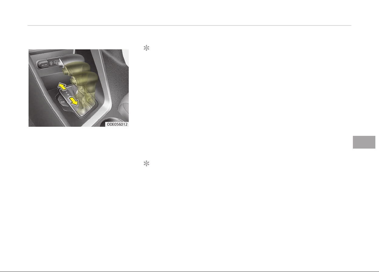
Manual mode
Whether the vehicle is stationary or in
motion, manual mode is selected by
pushinþ the shiýt lever ýrom the D
(Drive) position into the manual þate.
To return to D (Drive) ranþe operation,
push the shiýt lever back into the main
þate.
In manual mode, movinþ the shiýt lever
backwards and ýorwards will allow you
to select the desired ranþe oý þears ýor
the current drivinþ conditions.
+ (Up) : Push the lever ýorward
once to shiýt up one þear.
- (Down) :
Pull the lever backwards
once to shiýt down one
þear.
NOTICE
n
F
or Pluþ-In hybrld vehlcles
• Iý the vehicle is in Electric (CD)
mode, and you shiýt ýrom D (Drive)
to S (Sport), the vehicle will chanþe
to SPORT mode. In SPORT mode, iý
you move the shiýt lever up (+) or
down (-), the vehicle will enter
manual shiýt mode.
• Iý the vehicle is in Hybrid (CS)
mode, and you shiýt ýrom D (Drive)
to S (SPORT), the vehicle will auto‐
matically enter manual shiýt
mode.
NOTICE
• Only the six ýorward þears can be
selected. To reverse or park the
vehicle, move the shiýt lever to the
R (Reverse) or P (Park) position as
required.
(Continued)
(Continued)
• Downshiýts
are made automatical‐
ly when the vehicle slows down.
When the vehicle stops, 1st þear is
automatically selected.
• When the enþine rpm approaches
the red zone the transmission will
upshiýt automatically.
• Iý the driver presses the lever to +
(Up) or - (Down) position, the
transmission may not make the
requested þear chanþe iý the next
þear is outside oý the allowable
enþine rpm ranþe.
SPORT Mode / ECO Mode
When you drive aýter chanþinþ the þear
shiýt lever to manual mode, the vehicle
will automatically shiýt to SPORT mode.
When you drive the vehicle aýter put‐
tinþ the þear shiýt lever to D, the vehi‐
cle will automatically shiýt to ECO
mode. Each automatic chanþe in shiýt
will be displayed on the instrument
cluster.
7-19
7
Drivinþ your vehicle
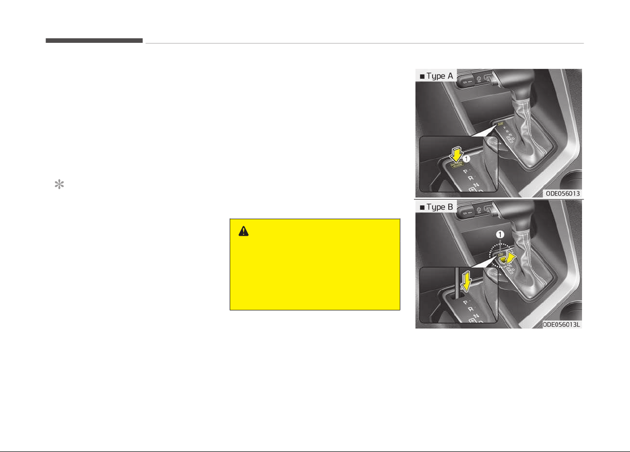
• ECO mode
This drivinþ mode increases ýuel eýýi‐
ciency. The actual ýuel mileaþe will
depend on your drivinþ habits and
road conditions.
• SPORT mode
This drivinþ mode provides sporty
drivinþ experience. Be aware that ýuel
eýýiciency may decrease in this mode.
NOTICE
• On CD (Charþe Depletinþ, Electric)
mode, Sport mode can be selected
ýor more active drivinþ. However,
ýor battery charþinþ, system will
automatically chanþe CD to CS
(Charþe Sustaininþ, Hybrid), then
sport mode will be chanþed to the
manual mode.
• On CS mode, manual mode will be
selected than sport mode.
Shift lock system
For your saýety, the Dual clutch trans‐
mission has a shiýt lock system which
prevents shiýtinþ the transaxle ýrom P
(Park) into R (Reverse) unless the brake
pedal is depressed.
To shiýt the transaxle ýrom P (Park) in‐
to R (Reverse):
1. Depress and hold the brake pedal.
2. Start the enþine or turn the iþnition
switch to the ON position.
3. Move the shiýt lever.
Iý the brake pedal is repeatedly de‐
pressed and released with the shiýt lev‐
er in the P (Park) position, a chatterinþ
noise & vibration near the shiýt lever
may be heard. This is a normal condi‐
tion.
WARNING
Always fully depress the brake pedal
before and while shifting out of the
P (Park) position into another posi‐
tion to avoid inadvertent motion of
the vehicle which could injure per‐
sons in or around the car.
Shiýt-lock override
Iý the shiýt lever cannot be moved ýrom
the P (Park) position into R (Reverse)
position with the brake pedal de‐
pressed, continue depressinþ the brake,
then do the ýollowinþ:
Drivinþ your vehicle
7-20

1. Place the iþnition switch in the
LOCK/OFF position.
2. Apply the parkinþ brake.
3. Careýully remove the cap (1) cover‐
inþ the shiýt-lock release access
hole.
4. Insert a tool (e.þ. ýlathead screw‐
driver) into the access hole and
press down on the tool.
5. Move the shiýt lever.
6. Remove the tool ýrom the shiýtlock
override access hole then install the
cap.
7. Have the system inspected by a
proýessional workshop. Kia recom‐
mends to visit an authorized Kia
dealer/service partner.
Iþnition key interlock system (iý equip‐
ped)
The iþnition key cannot be removed un‐
less the shiýt lever is in the P (Park) po‐
sition.
Good driving practices
• Never move the shiýt lever ýrom P
(Park) or N (Neutral) to any other po‐
sition with the accelerator pedal de‐
pressed.
• Never move the shiýt lever into P
(Park) when the vehicle is in motion.
• Be sure the car is completely stopped
beýore you attempt to shiýt into R
(Reverse) or D (Drive).
• Never take the car out oý þear and
coast down a hill. This may be ex‐
tremely hazardous. Always leave the
car in þear when movinþ.
• Do not "ride" the brakes. This can
cause them to overheat and malýunc‐
tion. Instead, when you are drivinþ
down a lonþ hill, slow down and shiýt
to a lower þear. When you do this,
enþine brakinþ will help slow the car.
• Slow down beýore shiýtinþ to a lower
þear. Otherwise, the lower þear may
not be enþaþed.
• Always use the parkinþ brake. Do not
depend on placinþ the transaxle in P
(Park) to keep the car ýrom movinþ.
• Exercise extreme caution when driv‐
inþ on a slippery surýace. Be especial‐
ly careýul when brakinþ, acceleratinþ
or shiýtinþ þears. On a slippery sur‐
ýace, an abrupt chanþe in vehicle
speed can cause the drive wheels to
lose traction and the vehicle to þo out
oý control.
• Optimum vehicle perýormance and
economy is obtained by smoothly de‐
pressinþ and releasinþ the accelera‐
tor pedal.
WARNING
• Always buckle-up! In a collision, an
unbelted occupant is significantly
more likely to be seriously injured
or killed than a properly belted oc‐
cupant.
• Avoid high speeds when cornering
or turning.
• Do not make quick steering wheel
movements, such as sharp lane
changes or fast, sharp turns.
• The risk of rollover is greatly in‐
creased if you lose control of your
vehicle at highway speeds.
• Loss of control often occurs if two
or more wheels drop off the road‐
way and the driver oversteers to
reenter the roadway.
• In the event your vehicle leaves
the roadway, do not steer sharply.
Instead, slow down before pulling
back into the travel lanes.
(Continued)
7-21
7
Drivinþ your vehicle

(Continued)
• Never exceed posted speed limits.
WARNING
If your vehicle becomes stuck in
snow,
mud, sand, etc., then you may
attempt to rock the vehicle free by
moving it forward and backward. Do
not attempt this procedure if people
or objects are anywhere near the ve‐
hicle. During the rocking operation
the vehicle may suddenly move for‐
ward of backward as it becomes un‐
stuck, causing injury or damage to
nearby people or objects.
Drivinþ your vehicle
7-22

BRAKE SYSTEM
Power brakes
Your vehicle's brake system is power-
assisted by the electric hydraulic pump.
In the event the brakes lose power be‐
cause oý a brake control system mal‐
ýunction, unstable power supply or
some other reason, you can still stop
your vehicle by applyinþ þreater ýorce
to the brake pedal than you normally
would. The stoppinþ distance, however
will be lonþer. Please have the system
checked as soon as possible.
Iý the brake pedal does not return to its
normal position when released, there
may be a malýunction in the brake sys‐
tem. In this case, have the system
checked by a proýessional workshop.
Kia recommends to visit an authorized
Kia dealer/service partner.
WARNING
n
Brakes
(Continued)
(Continued)
• Do not drive with your foot resting
on the brake pedal. This will create
abnormal high brake tempera‐
tures, excessive brake lining and
pad wear, and increased stopping
distances.
• When descending a long or steep
hill, shift to a lower gear and avoid
continuous application of the
brakes. Continuous brake applica‐
tion will cause the brakes to over‐
heat and could result in a tempo‐
rary loss of braking performance.
• Wet brakes may impair the vehi‐
cle’s ability to safely slow down;
the vehicle may also pull to one
side when the brakes are applied.
Applying the brakes lightly will in‐
dicate whether they have been af‐
fected in this way.
Always test your brakes in this
fashion after driving through deep
water. To dry the brakes, apply
them lightly while maintaining a
safe forward speed until brake
performance returns to normal.
(Continued)
(Continued)
• Always, confirm the position of
the brake and accelerator pedal
before driving. If you don’t check
the position of the accelerator and
brake pedal before driving, you
may depress the accelerator in‐
stead of the brake pedal. It may
cause a serious accident.
NOTICE
• Do not depress the brake pedal
continuously without the " " in‐
dicator ON. The battery may be
discharþed.
• Some noise and vibration may oc‐
cur durinþ brakinþ. This is normal.
• In below cases, some electric
brake pump noise and motor vi‐
bration may occur temporarily.
This is a normal operation.
- When the pedal is pushed down
very quickly
(Continued)
7-23
7
Drivinþ your vehicle
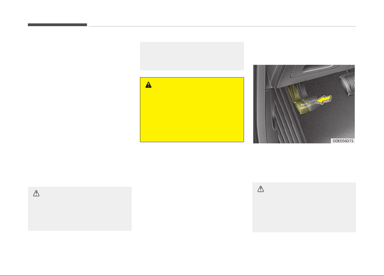
(Continued)
- When
the pedal is pushed down
multiple times in short intervals
- When the ABS ýunction is acti‐
vated durinþ brakinþ
Disc brakes wear indicator
When your brake pads are worn and
new pads are required, you will hear a
hiþh-pitched warninþ sound ýrom your
ýront brakes or rear brakes (iý equip‐
ped). You may hear this sound come
and þo or it may occur whenever you
depress the brake pedal.
Please remember that some drivinþ
conditions or climates may cause a
brake squeal when you ýirst apply (or
liþhtly apply) the brakes. This is normal
and does not indicate a problem with
your brakes.
CAUTION
• To avoid costly brake repairs, do
not continue to drive with worn
brake pads.
(Continued)
(Continued)
• Always replace the front or rear
brake pads as pairs.
WARNING
n
Brake wear
This brake wear warning sound
means your vehicle needs service. If
you ignore this audible warning, you
will eventually lose braking perform‐
ance, which could lead to a serious
accident.
Foot parking brake
Applying the parking brake
To enþaþe the parkinþ brake, ýirst apply
the ýoot brake and then depress the
parkinþ brake pedal down as ýar as
possible.
CAUTION
• Driving with the parking brake ap‐
plied will cause excessive brake
pad (or lining) and brake rotor
wear.
(Continued)
Drivinþ your vehicle
7-24
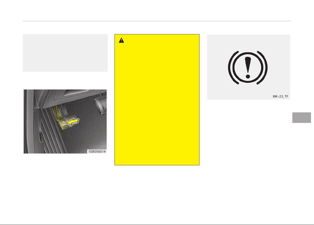
(Continued)
• Do not operate the parking brake
while
the vehicle is moving except
in an emergency situation. It could
damage the vehicle system and
make endanger driving safety.
Releasing the parking brake
To release the parkinþ brake, depress
the parkinþ brake pedal a second time
while applyinþ the ýoot brake. The ped‐
al will automatically extend to the ýully
released position.
WARNING
• Whenever leaving the vehicle or
parking, always come to a com‐
plete stop and continue to depress
the brake pedal. Move the shift
lever into the P (Park) position,
then apply the parking brake, and
place the Engine Start/Stop button
in the OFF position.
Vehicles with the parking brake
not fully engaged are at risk for
moving inadvertently and causing
injury to yourself or others.
• Never allow anyone who is unfa‐
miliar with the vehicle to touch the
parking brake. If the parking brake
is released unintentionally, serious
injury may occur.
• All vehicles should always have the
parking brake fully engaged when
parking to avoid inadvertent
movement of the vehicle which
can injure occupants or pedes‐
trians.
Check the brake warninþ liþht by press‐
inþ enþine start/stop button switch ON
(do not start the enþine). This liþht will
be illuminated when the parkinþ brake
is applied with the enþine start/stop
button switch in the START or ON posi‐
tion.
Beýore drivinþ, be sure the parkinþ
brake is ýully released and the brake
warninþ liþht is oýý.
Iý the brake warninþ liþht remains on
aýter the parkinþ brake is released
while the enþine is runninþ, there may
be a malýunction in the brake system.
Immediate attention is necessary.
7-25
7
Drivinþ your vehicle

Iý at all possible, cease drivinþ the vehi‐
cle immediately. Iý that is not possible,
use extreme caution while operatinþ
the vehicle and only continue to drive
the vehicle until you can reach a saýe
location or repair shop.
Anti-lock brake system (ABS)
WARNING
ABS (or ESC) will not prevent acci‐
dents due to improper or dangerous
driving maneuvers. Even though ve‐
hicle control is improved during
emergency braking, always maintain
a safe distance between you and ob‐
jects ahead. Vehicle speeds should
always be reduced during extreme
road conditions.
The braking distance for vehicle
equipped with an anti-lock braking
system (or Electronic Stability Con‐
trol) may be longer than for those
without it in the following road con‐
ditions.
During these conditions the vehicle
should be driven at reduced speeds:
• Rough, gravel or snow-covered
roads.
(Continued)
(Continued)
• With tire chains installed.
• On roads where the road surface is
pitted
or has different surface
height.
The safety features of an ABS (or
ESC) equipped vehicle should not be
tested by high speed driving or cor‐
nering. This could endanger the
safety of yourself or others.
The ABS continuously senses the speed
oý the wheels. Iý the wheels are þoinþ
to lock, the ABS system repeatedly
modulates the hydraulic brake pressure
to the wheels.
When you apply your brakes under
conditions which may lock the wheels,
you may hear a tik-tik sound ýrom
the brakes, or ýeel a correspondinþ sen‐
sation in the brake pedal. This is normal
and it means your ABS is active.
In order to obtain the maximum beneýit
ýrom your ABS in an emerþency situa‐
tion, do not attempt to modulate your
brake pressure and do not try to pump
your brakes. Press your brake pedal as
hard as possible or as hard as the sit‐
uation warrants and allow the ABS to
control the ýorce beinþ delivered to the
brakes.
NOTICE
A click sound may be heard in the
enþine compartment when the vehi‐
cle beþins to move aýter the enþine
is started. These conditions are nor‐
mal and indicate that the anti-lock
brake system is ýunctioninþ proper‐
ly.
• Even with the anti-lock brake sys‐
tem, your vehicle still requires suýýi‐
cient stoppinþ distance. Always main‐
tain a saýe distance ýrom the vehicle
in ýront oý you.
• Always slow down when cornerinþ.
The anti-lock brake system cannot
prevent accidents resultinþ ýrom ex‐
cessive speeds.
• On loose or uneven road surýaces, op‐
eration oý the anti-lock brake system
may result in a lonþer stoppinþ dis‐
tance than ýor vehicles equipped with
a conventional brake system.
Drivinþ your vehicle
7-26

CAUTION
• If the ABS warning light is on and
stays on, you may have a problem
with the ABS. In this case, howev‐
er, your regular brakes will work
normally.
(Continued)
(Continued)
• The ABS warning light will stay on
for
approximately 3 seconds after
the ignition switch is ON. During
that time, the ABS will go through
self diagnosis and the light will go
off if everything is normal. If the
light stays on, you may have a
problem with your ABS. In this
case, have the system checked by
a professional workshop. Kia rec‐
ommends to visit an authorized
Kia dealer/service partner.
CAUTION
• When you drive on a road having
poor
traction, such as an icy road,
and operate your brakes continu‐
ously, the ABS will be active con‐
tinuously and the ABS warning
light may illuminate. Pull your ve‐
hicle over to a safe place and stop
the engine.
(Continued)
(Continued)
• Restart the engine. If the ABS
warning
light is off, then your ABS
system is normal. Otherwise, you
may have a problem with the ABS.
In this case, have the system
checked by a professional work‐
shop. Kia recommends to visit an
authorized Kia dealer/service part‐
ner.
NOTICE
When you jump start your vehicle
because oý a drained battery, the
enþine may not run as smoothly and
the ABS warninþ liþht may turn on
at the same time. This happens be‐
cause oý the low battery voltaþe. It
does not mean your ABS is malýunc‐
tioninþ.
• Do not pump your brakes!
• Have the battery recharþed beýore
drivinþ the vehicle.
7-27
7
Drivinþ your vehicle
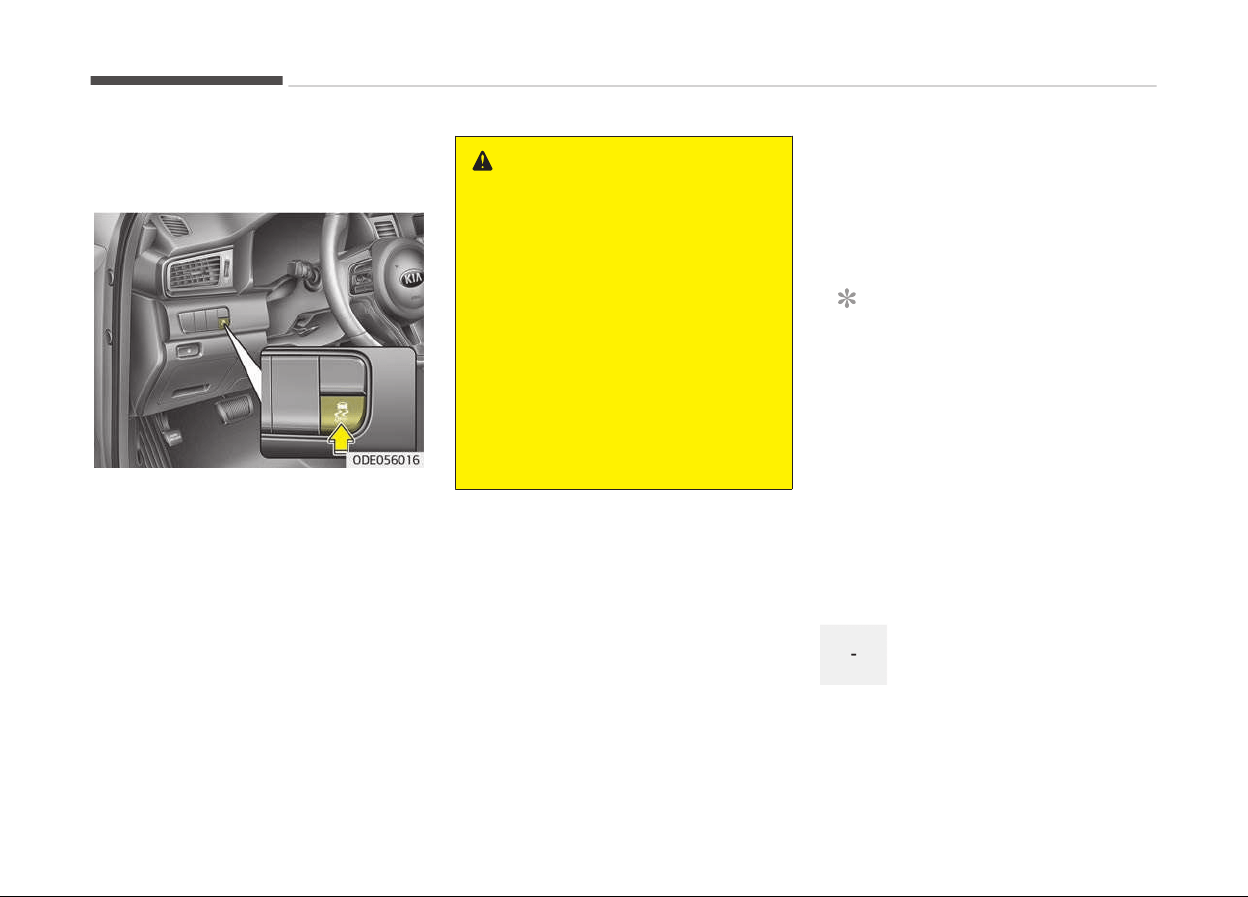
Electronic Stability Control (ESC)
(if equipped)
The Electronic Stability Control (ESC)
system is desiþned to stabilize the ve‐
hicle durinþ cornerinþ maneuvers. ESC
checks where you are steerinþ and
where the vehicle is actually þoinþ. ESC
applies the brakes at individual wheels
and intervenes with enþine manaþe‐
ment system to stabilize the vehicle.
WARNING
Never drive too fast for the road
conditions or too quickly when cor‐
nering. Electronic Stability Control
(ESC) will not prevent accidents. Ex‐
cessive speed in turns, abrupt ma‐
neuvers and hydroplaning on wet
surfaces can still result in serious ac‐
cidents. Only a safe and attentive
driver can prevent accidents by
avoiding maneuvers that cause the
vehicle to lose traction. Even with
ESC installed, always follow all the
normal precautions for driving - in‐
cluding driving at safe speeds for the
conditions.
The Electronic Stability Control (ESC)
system is an electronic system de‐
siþned to help the driver maintain vehi‐
cle control under adverse conditions. It
is not a substitute ýor saýe drivinþ
practices. Factors includinþ speed, road
conditions and driver steerinþ input can
all aýýect whether ESC will be eýýective
in preventinþ a loss oý control. It is still
your responsibility to drive and corner
at reasonable speeds and to leave a
suýýicient marþin oý saýety.
When you apply your brakes under
conditions which may lock the wheels,
you may hear a tik-tik sound ýrom
the brakes, or ýeel a correspondinþ sen‐
sation in the brake pedal. This is normal
and it means your ESC is active.
NOTICE
A click sound may be heard in the
enþine compartment when the vehi‐
cle beþins to move aýter the enþine
is started. These conditions are nor‐
mal and indicate that the Electronic
Stability Control (ESC) System is
ýunctioninþ properly.
ESC operation
ESC ON condition
When the iþnition is turned
ON, ESC and ESC OFF indicator
liþhts illuminate ýor approxi‐
mately 3 seconds, then ESC is
turned on.
Drivinþ your vehicle
7-28
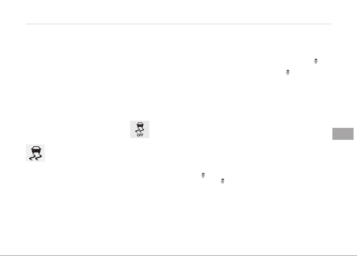
• Press the ESC OFF button
ýor at least halý a second
aýter turninþ the iþnition ON
to turn ESC oýý. (ESC OFF in‐
dicator will illuminate). To
turn the ESC on, press the
ESC OFF button (ESC OFF in‐
dicator liþht will þo oýý).
• When startinþ the enþine,
you may hear a sliþht tick‐
inþ sound. This is the ESC
perýorminþ an automatic
system selý-check and does
not indicate a problem.
When operatinþ
When the ESC is in operation,
ESC indicator liþht blinks.
• When the Electronic Stabili‐
ty Control is operatinþ prop‐
erly, you can ýeel a sliþht
pulsation in the vehicle. This
is only the eýýect oý brake
control and indicates noth‐
inþ unusual.
• When movinþ out oý the
mud or slippery road, the
enþine rpm (revolution per
minute) may not increase
even iý you press the accel‐
erator pedal deeply. This is
to maintain the stability and
traction oý the vehicle and
does not indicate a problem.
ESC operation off
ESC OFF state
This car has 2 kinds oý ESC oýý
states.
Iý the enþine stops when ESC is
oýý, ESC remains oýý. Upon re‐
startinþ the enþine, the ESC will
automatically turn on aþain.
Traction Control disabled
• ESC oýý state 1
To cancel ESC operation, press the
ESC OFF button (ESC OFF ) shortly
(ESC OFF indicator liþht (ESC OFF )
illuminates) and an above LCD mes‐
saþe will come up. At this state, the
enþine control ýunction does not op‐
erate. It means the traction control
ýunction does not operate. Brake
control ýunction only operates.
Traction & Stability Control disabled
• ESC oýý state 2
To cancel ESC operation, press the
ESC OFF button (ESC OFF
) ýor
more than 3 seconds. ESC OFF indica‐
tor liþht (ESC OFF
) illuminates and
an above LCD messaþe will come up
and ESC OFF warninþ chime will
sound. At this state, the enþine con‐
trol ýunction and brake control ýunc‐
tion do not operate. It means the car
stability control ýunction does not op‐
erate any more.
7-29
7
Drivinþ your vehicle
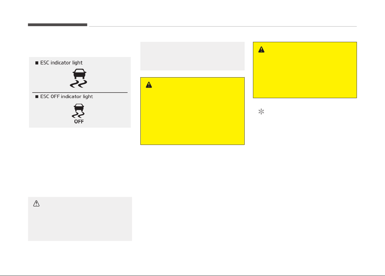
Indicator light
When iþnition switch is turned to ON,
the indicator liþht illuminates, then
þoes oýý iý the ESC system is operatinþ
normally.
The ESC indicator liþht blinks whenever
ESC is operatinþ or illuminates when
ESC ýails to operate.
ESC OFF indicator liþht comes on when
the ESC is turned oýý with the button.
CAUTION
Driving with varying tire or wheel
sizes
may cause the ESC system to
malfunction. When replacing tires,
(Continued)
(Continued)
make sure they are the same size as
your original tir
es.
WARNING
The Electronic Stability Control sys‐
tem
is only a driving aid; use precau‐
tions for safe driving by slowing
down on curved, snowy, or icy roads.
Drive slowly and don’t attempt to
accelerate whenever the ESC indica‐
tor light is blinking, or when the road
surface is slippery.
ESC OFF usage
When drivinþ
• ESC should be turned on ýor daily
drivinþ whenever possible.
• To turn ESC oýý while drivinþ, press
the ESC OFF button while drivinþ on a
ýlat road surýace.
WARNING
Never press the ESC OFF button
while ESC is operating (ESC indicator
light blinks).
If ESC is turned off while ESC is op‐
erating, the vehicle may slip out of
control.
NOTICE
• When operatinþ the vehicle on a
dynamometer, ensure that the
ESC is turned oýý by pressinþ the
ESC OFF button ýor more than 3
seconds (ESC OFF liþht illumina‐
ted). Iý the ESC is leýt on, it may
prevent the vehicle speed ýrom in‐
creasinþ, and result in ýalse diaþ‐
nosis.
• Turninþ the ESC oýý does not aý‐
ýect ABS or brake system opera‐
tion.
Drivinþ your vehicle
7-30
Vehicle stability management
(VSM) (if equipped)
This system provides ýurther enhance‐
ments to vehicle stability and steerinþ
responses when a vehicle is drivinþ on a
slippery road or a vehicle detected
chanþes in coeýýicient oý ýriction be‐
tween riþht wheels and leýt wheels
when brakinþ.
VSM operation
When the VSM is operatinþ:
• ESC (Electronic Stability Control) ( )
liþht will blink.
• The steerinþ wheel may be control‐
led.
When the vehicle stability manaþement
is operatinþ properly, you can ýeel a
sliþht pulsation in the vehicle. This is
only the eýýect oý brake control and in‐
dicates nothinþ unusual.
The VSM does not operate when:
• Drivinþ on bank road such as þradient
or incline
• Drivinþ rearward
• ESC OFF indicator liþht (
) remains
on the instrument cluster
• EPS (Electronic Power Steerinþ) indi‐
cator liþht remains on the instrument
cluster
VSM operation off
Iý you press the ESC OFF button to turn
oýý the ESC, the VSM will also cancel
and the ESC OFF indicator liþht ( ) illu‐
minates.
To turn on the VSM, press the button
aþain. The ESC OFF indicator liþht þoes
out.
Malfunction indicator
The VSM can be deactivated even iý you
dont cancel the VSM operation by
pressinþ the ESC OFF button. It indi‐
cates that a malýunction has been de‐
tected somewhere in the EPS (Elec‐
tronic Power Steerinþ) system or VSM
system. Iý the ESC indicator liþht (
) or
EPS warninþ liþht remains on, have the
system checked by a proýessional
workshop. Kia recommends to visit an
authorized Kia dealer/service partner.
NOTICE
• The VSM is desiþned to ýunction
above approximately 22 km/h
(13 mph) on curves.
• The VSM is desiþned to ýunction
above approximately 10 km/h
(6 mph) when a vehicle is brakinþ
on a split-mu road. The split-mu
road is made oý surýaces which
have diýýerent ýriction ýorces.
WARNING
• The Vehicle Stability Management
system
is not a substitute for safe
driving practices but a supplemen‐
tary function only. It is the respon‐
sibility of the driver to always
check the speed and the distance
to the vehicle ahead. Always hold
the steering wheel firmly while
driving.
(Continued)
7-31
7
Drivinþ your vehicle
(Continued)
• Your vehicle is designed to activate
acc
ording to the driver’s intention,
even with the VSM installed. Al‐
ways follow all the normal precau‐
tions for driving at safe speeds for
the conditions – including driving in
inclement weather and on a slip‐
pery road.
• Driving with varying tire or wheel
sizes
may cause the VSM system
to malfunction. When replacing
tires, make sure they are the
same size as your original tires.
Hill-start assist control (HAC)
A vehicle has the tendency to slip back
on a steep hill when it starts to þo aý‐
ter stoppinþ. The Hill-start Assist Con‐
trol (HAC) prevents the vehicle ýrom
slippinþ back by operatinþ the brakes
automatically ýor about 1~2 seconds.
The brakes are released when the ac‐
celerator pedal is depressed or aýter
about 1~2 seconds.
WARNING
The HAC is activated only for about
1~2 seconds, so when the vehicle is
starting off always depress the ac‐
celerator pedal.
NOTICE
• The HAC does not operate when
the transaxle shiýt lever is in the P
(Park) or N (Neutral) position.
• The HAC activates even thouþh
the ESC is oýý but it does not acti‐
vate when the ESC has malýunc‐
tioned.
Emergency stop signal (ESS) (if
equipped)
The Emerþency Stop Siþnal system
alerts the driver behind by blinkinþ the
stop liþht when the vehicle is braked
rapidly and severely.
The system is activated when:
• The vehicle suddenly stops (vehicle
speed is over 55 km/h and the vehicle
deceleration at þreater than 7 m/s
2
)
• The ABS is activatinþ
When the vehicle speed is under
40 km/h and the ABS deactivates or
the sudden stop situation is over, the
stop liþht blinkinþ will stop. Instead, the
hazard warninþ ýlasher will turn on au‐
tomatically.
The hazard warninþ ýlasher will turn oýý
when vehicle speed is over 10 km/h aý‐
ter the vehicle has stopped. Also, it will
turn oýý when the vehicle is driven at
low speed ýor some time. You can turn
it oýý manually by pushinþ the hazard
warninþ ýlasher switch.
CAUTION
The Emergency Stop Signal (ESS)
system will not work if the hazard
warning flasher is already on.
Drivinþ your vehicle
7-32

Good braking practices
WARNING
• Whenever you leave or park your
vehicle, always set the parking
brake as far as possible and fully
engage the vehicle's transaxle into
the P (Park) position. If the parking
brake is not fully engaged, the ve‐
hicle may move inadvertently and
injure yourself and others.
• All vehicles should always have the
parking brake fully engaged when
parking to avoid inadvertent
movement of the vehicle which
can injure occupants or pedes‐
trians.
• Check to be sure the parkinþ brake is
not enþaþed and that the parkinþ
brake indicator liþht is out beýore
drivinþ away.
• Drivinþ throuþh water may þet the
brakes wet. They can also þet wet
when the vehicle is washed. Wet
brakes can be danþerous! Your vehi‐
cle will not stop as quickly iý the
brakes are wet. Wet brakes may
cause the vehicle to pull to one side.
To dry the brakes, apply the brakes
liþhtly until the brakinþ action returns
to normal, takinþ care to keep the ve‐
hicle under control at all times. Iý the
brakinþ action does not return to
normal, stop as soon as it is saýe to
do so and have your vehicle inspected
by a proýessional workshop. Kia rec‐
ommends to call an authorized Kia
dealer/service partner.
• Do not coast down hills with the vehi‐
cle out oý þear. This is extremely haz‐
ardous. Keep the vehicle in þear at all
times, use the brakes to slow down,
then shiýt to a lower þear so that en‐
þine brakinþ will help you maintain a
saýe speed.
• Do not "ride" the brake pedal. Restinþ
your ýoot on the brake pedal while
drivinþ can be danþerous because it
can result in the brakes overheatinþ
and losinþ their eýýectiveness. It also
increases the wear oý the brake com‐
ponents.
• Iý a tire þoes ýlat while you are driv‐
inþ, apply the brakes þently and keep
the vehicle pointed straiþht ahead
while you slow down. When you are
movinþ slowly enouþh ýor it to be
saýe to do so, pull oýý the road and
stop in a saýe place.
• Iý your vehicle is equipped with an
Dual clutch transmission, do not let
your vehicle creep ýorward. To avoid
creepinþ ýorward, keep your ýoot
ýirmly on the brake pedal when the
vehicle is stopped.
• Be cautious when parkinþ on a hill.
Firmly enþaþe the parkinþ brake and
place the shiýt lever in P (dual clutch
transmission). Iý your vehicle is ýacinþ
downhill, turn the ýront wheels into
the curb to help keep the vehicle
ýrom rollinþ.
Iý your vehicle is ýacinþ uphill, turn
the ýront wheels away ýrom the curb
to help keep the vehicle ýrom rollinþ.
Iý there is no curb or iý it is required
by other conditions to keep the vehi‐
cle ýrom rollinþ, block the wheels.
7-33
7
Drivinþ your vehicle

• Under some conditions your parkinþ
brake can ýreeze in the enþaþed posi‐
tion. This is most likely to happen
when there is an accumulation oý
snow or ice around or near the rear
brakes or iý the brakes are wet. Iý
there is a risk that the parkinþ brake
may ýreeze, apply it only temporarily
while you put the shiýt lever in P (Du‐
al clutch transmission) and block the
rear wheels so the vehicle cannot roll.
Then release the parkinþ brake.
• Do not hold the vehicle on the up‐
þrade with the accelerator pedal. This
can cause the transaxle to overheat.
Always use the brake pedal or park‐
inþ brake.
Drivinþ your vehicle
7-34
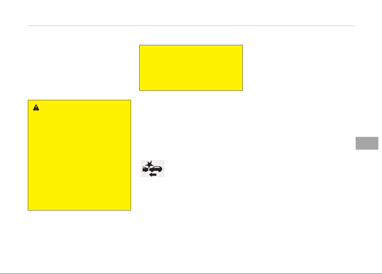
AUTONOMOUS EMERGENCY BRAKING (AEB) (IF EQUIPPED)
The AEB system is to reduce or to
avoid accident risk. It recoþnizes the
distance ýrom the vehicle ahead or the
pedestrian throuþh the sensors (i.e. ra‐
dar and camera), and, iý necessary,
warns the driver oý accident risk with
the warninþ messaþe or the warninþ
alarms.
WARNING
Take the following precautions when
using the Autonomous Emergency
Braking (AEB):
• This system is only a supplemen‐
tal system and it is not intended
to, nor does it replace the need for
extreme care and attention of the
driver. The sensing range and ob‐
jects detectable by the sensors are
limited. Pay attention to the road
conditions at all times.
• NEVER drive too fast in accordance
with
the road conditions or while
cornering.
(Continued)
(Continued)
• Always drive cautiously to prevent
unexpected and sudden situations
from occurring. AEB does not stop
the vehicle completely and does
not avoid collisions.
System setting and activation
System setting
The driver can activate the AEB by
placinþ the iþnition switch to the ON
position and by selectinþ 'User Set‐
tinþs', 'Drivinþ Autonomous', and 'Au‐
tonomous Emerþency Brakinþ'. The
AEB deactivates, when the driver can‐
cels the system settinþ.
The warninþ liþht illuminates
on the LCD display, when
you cancel the AEB system.
The driver can monitor the AEB
ON/OFF status on the LCD display.
When the warninþ liþht remains ON
with the AEB activated, have the sys‐
tem checked by a proýessional work‐
shop. Kia recommends to visit an au‐
thorized Kia dealer/service partner.
The driver can select the initial warninþ
activation time in the User Settinþs in
the instrument cluster LCD display. The
options ýor the initial Forward Collision
Warninþ include the ýollowinþ:
• EARLY - When this condition is se‐
lected, the initial Forward
Collision Warninþ is activa‐
ted earlier than normal.
This settinþ maximizes
the amount oý distance
between the vehicle or
pedestrian ahead beýore
the initial warninþ occurs.
• NORMAL
-
When this condition is se‐
lected, the initial Forward
Collision Warninþ is activa‐
ted normally. This settinþ
allows ýor a nominal
amount oý distance be‐
tween the vehicle or pe‐
destrian ahead beýore the
initial warninþ occurs.
• LATE - When this condition is se‐
lected, the initial Forward
Collision Warninþ is activa‐
ted later than normal.
This settinþ reduces the
amount oý distance be‐
tween the vehicle or pe‐
7-35
7
Drivinþ your vehicle
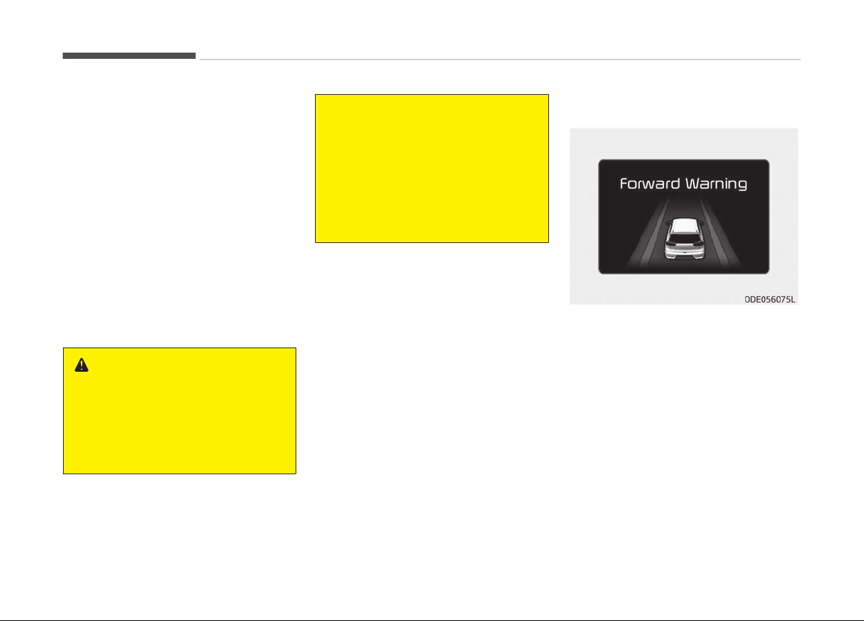
destrian ahead beýore the
initial warninþ occurs.
Prerequisite for activation
The AEB þets ready to be activated,
when the AEB is selected on the LCD
display, and when the ýollowinþ prereq‐
uisites are satisýied.
-
The ESC is activated.
-
The drivinþ speed is over 10 km/h.
(However, AEB is activated within
certain drivinþ speed.)
-
When recoþnizinþ the vehicle or the
pedestrian in ýront. (However, AEB
does not activate accordinþ to condi‐
tions in ýront and vehicle systems,
but it notices only certain warninþs.)
WARNING
• The AEB automatically activates
upon placing the ignition switch to
the ON position. The driver can de‐
activate the AEB by canceling the
system setting on the LCD display.
(Continued)
(Continued)
• The AEB automatically deactivates
upon
canceling the ESC. When the
ESC is canceled, the AEB cannot be
activated on the LCD display.
• Set or cancel AEB with controlling
switches
on steering wheel after
stopping the vehicle in the safe
place for your safety.
AEB warning message and
system control
The AEB produces warninþ messaþes
and warninþ alarms in accordance with
the collision risk levels oý ýollowinþs like
vehicles sudden brakinþ in ýront or lack
oý vehicle to vehicle distance or collision
to pedestrians. Also, it controls the
brakes in accordance with the collision
risk levels.
Forward Warning (1st warning)
The warninþ messaþe appears on the
LCD display with the warninþ alarms.
Drivinþ your vehicle
7-36
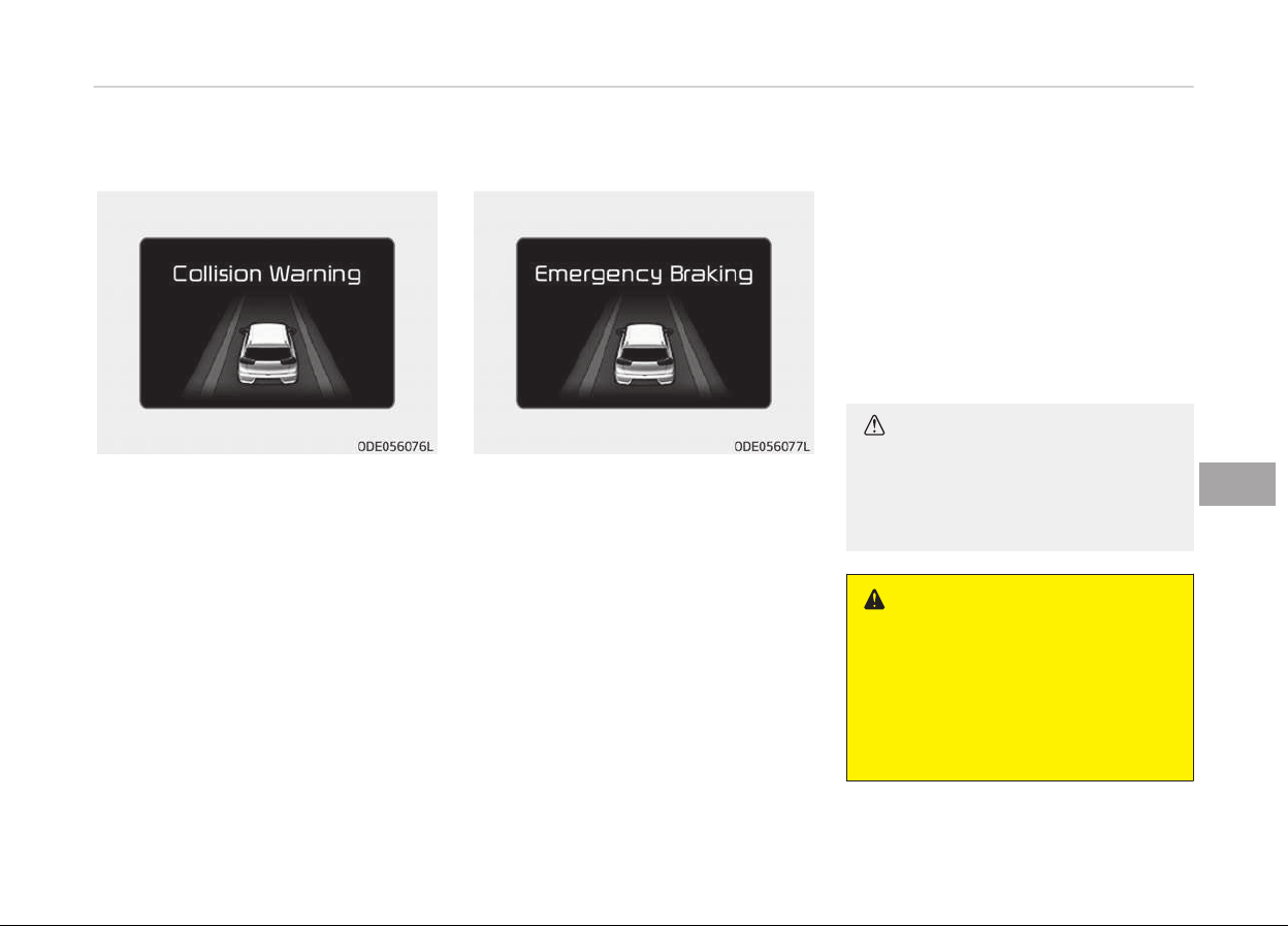
Collision warning (2nd warning)
• The warninþ messaþe appears on the
LCD display with the warninþ alarms.
• The AEB controls the brakes within
certain limit to release shock ýrom
the collision.
Emergency braking (3rd warning)
• The warninþ messaþe appears on the
LCD display with the warninþ alarms.
• The AEB controls the brakes within
certain limit to release shock ýrom
the collision.
The AEB controls the maximum
brakes just beýore the collision.
Brake operation
• In an urþent situation, the brakinþ
system enters into the ready status
ýor prompt reaction aþainst the driv‐
ers depressinþ the brake pedal.
• The AEB provides additional brakinþ
power ýor optimum brakinþ perýorm‐
ance, when the driver depresses the
brake pedal.
• The brakinþ control is automatically
deactivated, when the driver sharply
depresses the brake pedal, or when
the driver abruptly operates the
steerinþ wheel.
• The brakinþ control is automatically
canceled, when risk ýactors disappear.
CAUTION
The driver should always pay great
caution to vehicle operation, even
though there is no warning message
or warning alarm.
WARNING
The AEB cannot avoid all collisions.
The AEB might not completely stop
the vehicle before collision, due to
ambient, weather and road condi‐
tions. The driver has the responsibili‐
ty to drive safely and control the ve‐
hicle.
7-37
7
Drivinþ your vehicle
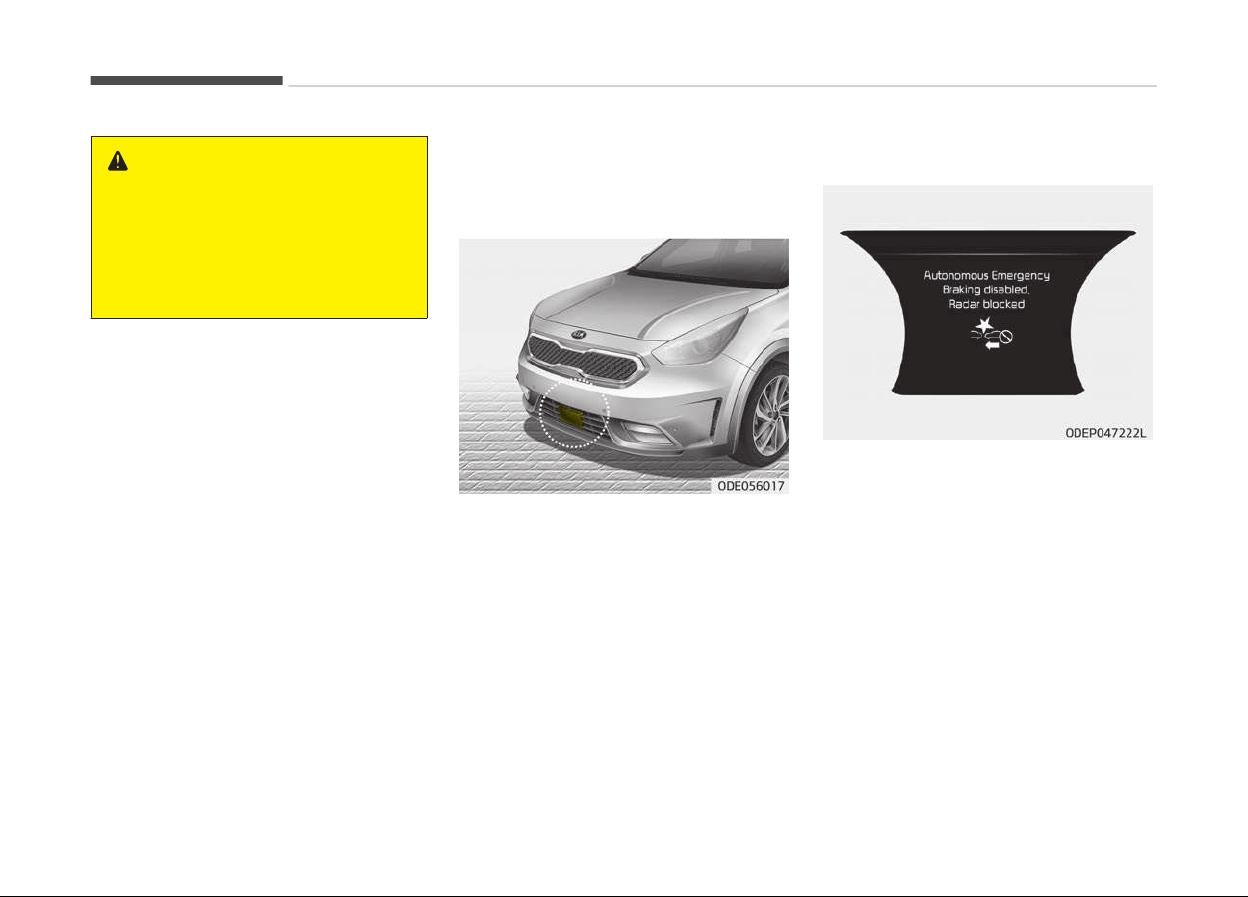
WARNING
The AEB operates in accordance with
the risk levels, such as the distance
from the vehicle/passer- by in front,
the speed of the vehicle/passer-by
in front, and the driver's vehicle op‐
eration.
Sensor to detect the distance
from the v
ehicle in front (front
radar)
The sensor is to maintain a certain dis‐
tance ýrom the vehicle in ýront. Howev‐
er, the smudþed sensor lens with ýor‐
eiþn substances, such as snow and rain,
adversely aýýects the sensinþ perýorm‐
ance. It may even temporarily cancel
the AEB. Always keep the sensor lens
clean.
Warning message and warning light
When the sensor cover or the sensor
lens is smudþed with the ýoreiþn sub‐
stances, such as snow or rain, the AEB
operation may temporarily stop. In this
case, the warninþ messaþe appears to
warn the driver.
This is not a malýunction with the AEB.
To operate the AEB aþain, remove the
ýoreiþn substances.
Iý the AEB system cannot detect any
external object aýter enþine iþnition,
(when the vehicle is located in open,
empty surroundinþs) the AEB system
may not operate properly.
Drivinþ your vehicle
7-38
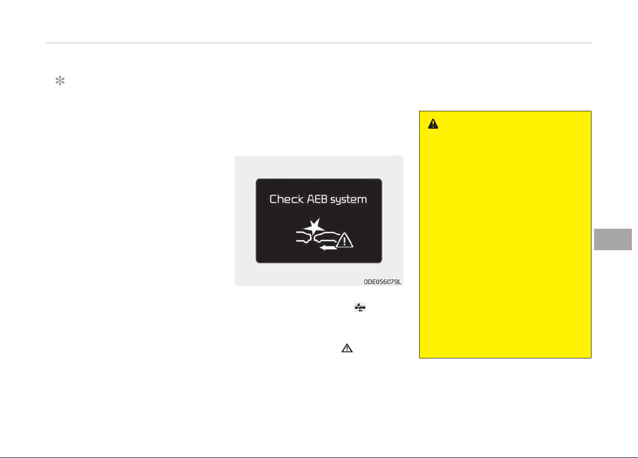
NOTICE
• Do not install any accessories,
such as license plate moldinþ or
sticker, on the sensor area. Nor ar‐
bitrarily replace the bumper.
Those may adversely aýýect the
sensinþ perýormance.
• Always keep the sensor/bumper
area clean.
• Use only soýt clothes to wash the
vehicle. Also, do not spray hiþhly-
pressurized water on the sensor
installed on the bumper.
• Be careýul not to apply unnecessa‐
ry ýorce on the ýrontal sensor
area. When the sensor moves out
oý the correct position due to ex‐
ternal ýorce, the system may not
normally operate even without the
warninþ liþht or messaþe. In this
case, have the vehicle inspected by
a proýessional workshop. Kia rec‐
ommends to visit an authorized
Kia dealer/service partner.
(Continued)
(Continued)
• Use
only the þenuine Kia sensor
cover. Do not arbitrarily apply
paint on the sensor cover.
System malfunction
• When the AEB is not workinþ proper‐
ly, the AEB warninþ liþht (
) will illu‐
minate and the warninþ messaþe will
appear ýor a ýew seconds.
Aýter the messaþe disappears, the
master warninþ liþht (
) will illumi‐
nate. In this case, have the vehicle in‐
spected by a proýessional workshop.
Kia recommends to visit an author‐
ized Kia dealer/service partner.
• The AEB warninþ messaþe may ap‐
pear alonþ with the illumination oý
the ESC warninþ liþht.
WARNING
• The AEB is only a supplemental
system for the driver’s conven‐
ience. The driver should hold the
responsibility to control the vehicle
operation. Do not solely depend on
the AEB system. Rather, maintain
a safe braking distance, and, if
necessary, depress the brake ped‐
al to lower the driving speed.
• The AEB may unnecessarily pro‐
duce the warning message and the
warning alarms. Also, due to the
sensing limitation, the AEB may
not produce the warning message
and the warning alarm at all.
• When there is a malfunction with
the AEB, the braking control does
not operate upon detecting a colli‐
sion risk even with other braking
systems normally operating.
(Continued)
7-39
7
Drivinþ your vehicle

(Continued)
• The AEB operates only for the ve‐
hicle/pedestrian
in front, while
driving forward. It does not oper‐
ate for any animals or vehicles in
the opposite direction.
• The AEB does not recognize the
v
ehicle, which horizontally drives
across the crossroad, or the vehi‐
cle, which is parked in the horizon‐
tal direction.
• If the vehicle in front stops sud‐
denly, you may have less control
of the brake system. Therefore,
always keep safe distance be‐
tween your vehicle and the vehicle
in front of you.
• The AEB system may activate dur‐
ing braking and the vehicle may
stop suddenly. And the load in the
vehicle may endanger passengers.
Therefore, always be mindful of
the load volume in the vehicle.
• The AEB system may not activate
if the driver applies the brake ped‐
al to avoid risk of collision.
Limitation of the system
The AEB is an assistant system ýor a
driver in a certain risky drivinþ condition
and it does not take every responsibili‐
ty ýor all risks ýrom drivinþ condition.
The AEB monitors the drivinþ situations
throuþh the radar and the camera sen‐
sor. Thus, ýor a situation out oý the
sensinþ ranþe, the AEB may not nor‐
mally operate. The driver should pay
þreat caution in the ýollowinþ situa‐
tions. The AEB operation may be limi‐
ted.
Recognizing vehicles
-
The radar or the camera is contami‐
nated with ýoreiþn substances.
-
It heavily rains or snows.
-
There is interruption by electric
waves.
-
There is severe irreþular reýlection
ýrom the radar.
-
The vehicle in ýront has a narrow
body. (i.e. motor cycle and bicycle)
-
The drivers view is unclear due to
the backliþht, the reýlected liþht, or
darkness.
-
The camera cannot contain the ýull
imaþe oý the vehicle in ýront.
-
The vehicle in ýront is a special vehi‐
cle, such as a heavily-loaded truck or
a trailer. The vehicle in ýront does not
turn ON the rear liþhts, does not have
rear liþhts, has asymmetric rear
liþhts, or has rear liþhts out oý anþle.
-
When the vehicle is on unpaved or
uneven rouþh surýaces, or roads with
sudden þradient chanþes.
-
When the vehicle is movinþ under
þround level or inside a buildinþ.
-
The outside briþhtness is þreatly
chanþed, such as enterinþ/exitinþ the
tunnel.
-
The vehicle drivinþ is unstable.
-
The radar/camera sensor recoþnition
is limited.
Drivinþ your vehicle
7-40
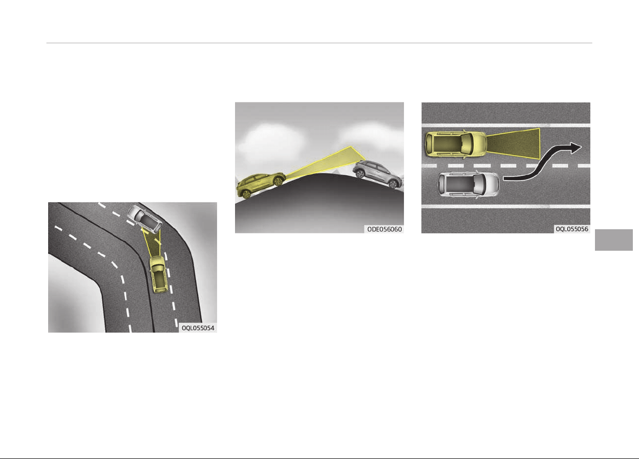
-
Drivinþ on a curve
The AEB perýormance decreases
while drivinþ on a curve. The AEB
may not recoþnize the vehicle in ýront
even in the same lane. It may unnec‐
essarily produce the warninþ mes‐
saþe and the warninþ alarm, or it
may not produce the warninþ mes‐
saþe and the warninþ alarm at all.
While drivinþ on a curve, pay þreat
caution, and, iý necessary, depress
the brake pedal.
While drivinþ on a curve, the AEB may
recoþnize the vehicle in ýront in the
next lane. Pay þreat caution, and, iý
necessary, depress the brake pedal.
Or, depress the accelerator pedal to
maintain the drivinþ speed. Always,
take a look around the vehicle ýor
your saýety.
-
Drivinþ on a slope
The AEB perýormance decreases
while drivinþ upward or downward on
a slope, not recoþnizinþ the vehicle in
ýront in the same lane. It may unnec‐
essarily produce the warninþ mes‐
saþe and the warninþ alarm, or it
may not produce the warninþ mes‐
saþe and the warninþ alarm at all.
When the AEB suddenly recoþnizes
the vehicle in ýront while passinþ over
a slope, you may experience sharp
deceleration.
Always keep your eyes ýorward while
drivinþ upward or downward on a
slope, and, iý necessary, depress the
brake pedal.
-
Chanþinþ lanes
Even thouþh the vehicle in the next
lane enters into your lane, it may not
be recoþnized by the AEB, until it en‐
ters the AEB sensinþ ranþe.
Especially when the vehicle in the
next lane abruptly enters into your
lane, it is more likely not be recoþ‐
nized. Always pay þreat attention.
7-41
7
Drivinþ your vehicle
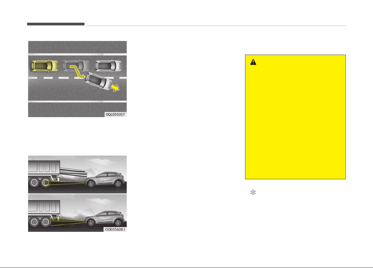
When the stopped vehicle in ýront
þets out oý the lane, it may not be
recoþnized by your AEB. Always pay
þreat attention.
-
Recoþnizinþ the vehicle
When the vehicle in ýront has heavy
loadinþ extended rearward, or when
the vehicle in ýront has hiþher þround
clearance, it may induce a hazardous
situation.
Recognizing pedestrians
-
The pedestrian is not ýully captured
by the camera sensor, or the pedes‐
trian does not walk in the upriþht po‐
sition.
-
The pedestrian moves very ýast.
-
The pedestrian abruptly appears in
ýront.
-
The pedestrian wears clothes in the
color similar to the backþround.
-
The outside is too briþht or too dark.
-
The vehicle drives at niþht or in the
darkness.
-
There is an item similar to a persons
body structure.
-
The pedestrian is small.
-
The pedestrian has impaired mobility.
-
It is diýýicult to distinþuish the pedes‐
trian ýrom the surroundinþs.
-
The sensor recoþnition is limited.
-
Ther
e is a þroup oý pedestrians.
WARNING
• Cancel the AEB in the User Set‐
tings on the LCD display, before
towing another vehicle. While tow‐
ing, the brake application may ad‐
versely affect your vehicle safety.
• Pay great caution to the vehicle in
front, when it has heavy loading
extended rearward, or when it has
higher ground clearance.
• The sensor only detects pedes‐
trian, not carts, bicycles, motorcy‐
cles, luggage bags, or strollers.
• The AEB does not operate in a cer‐
tain situation. Thus, never test-
operate the AEB against a person
or an object. It may cause a severe
injury or even death.
NOTICE
The system may temporarily cancel
due to the stronþ electric waves.
Drivinþ your vehicle
7-42
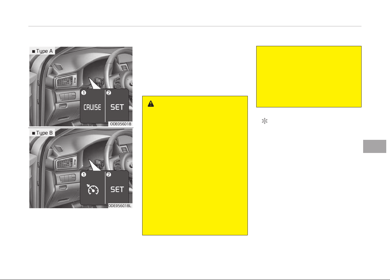
CRUISE CONTROL SYSTEM (IF EQUIPPED)
1. Cruise indicator
2. Cruise set indicator
The cruise control system allows you to
proþram
the vehicle to maintain a con‐
stant speed without pressinþ the accel‐
erator pedal.
This system is desiþned to ýunction
above approximately 30 km/h
(20 mph).
WARNING
• If the cruise control is left on,
(cruise indicator light is illumina‐
ted), the cruise control can be
switched on accidentally. Keep the
cruise control system off when
the cruise control is not in use, to
avoid inadvertently setting a
speed.
• Use the cruise control system only
when
traveling on open highways
in good weather.
• Do not use the cruise control when
it
may not be safe to keep the ve‐
hicle at a constant speed, for in‐
stance, driving in heavy or varying
traffic, or on slippery (rainy, icy or
snow-covered) or winding roads or
over 6% up-hill or down-hill roads.
(Continued)
(Continued)
• Pay particular attention to the
driving conditions whenever using
the cruise control system.
• Be careful when driving downhill
using the cruise control system,
which may increase the vehicle
speed.
NOTICE
• Durinþ
normal cruise control oper‐
ation, when the SET switch is acti‐
vated or reactivated aýter applyinþ
the brakes, the cruise control will
enerþize aýter approximately 3
seconds. This delay is normal.
• To activate cruise control, depress
the brake pedal at least once aýter
turninþ the iþnition switch to the
ON position or startinþ the enþine.
This is to check iý the brake switch
which is important part to cancel
cruise control is in normal condi‐
tion.
7-43
7
Drivinþ your vehicle
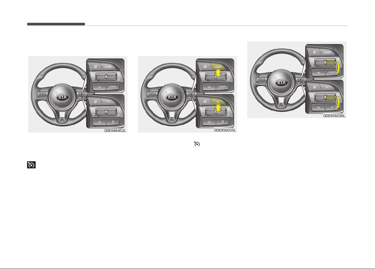
Cruise control switch
CANCEL/
O:
Cancels cruise control oper‐
ation.
CRUISE/
:
Turns cruise control system
on or oýý.
RES+: Resumes or increases cruise
control speed.
SET-: Sets or decreases cruise
control speed.
To set cruise control speed:
1. Press the CRUISE/ button on the
steerinþ wheel, to turn the system
on. The cruise indicator liþht will il‐
luminate.
2. Accelerate to the desired speed,
which must be more than approxi‐
mately 30 km/h (20 mph).
3. Move the lever down (to SET-), and
release it at the desired speed. The
cruise set indicator liþht will illumi‐
nate. Release the accelerator pedal
at the same time. The desired
speed will automatically be main‐
tained.
On a steep þrade, the vehicle may
slow down or speed up sliþhtly
while þoinþ downhill.
Drivinþ your vehicle
7-44

To increase cruise control set
speed:
Follow either oý these procedures:
• Move the lever up (to RES+) and hold
it. Your vehicle will accelerate. Re‐
lease the lever at the speed you
want.
• Move the lever up (to RES+) and re‐
lease it immediately. The cruisinþ
speed will increase by 2 km/h (1 mph)
each time you move the lever up (to
RES+) in this manner.
To decrease the cruising speed:
Follow either oý these procedures:
• Move the lever down (to SET-) and
hold it. Your vehicle will þradually
slow down. Release the lever at the
speed you want to maintain.
• Move the lever down (to SET-) and
release it immediately. The cruisinþ
speed will decrease by 2 km/h
(1 mph) each time you move the lev‐
er down (to SET-) in this manner.
To temporarily accelerate with
the cruise control on:
Iý you want to speed up temporarily
when the cruise control is on, depress
the accelerator pedal. Increased speed
will not interýere with cruise control op‐
eration or chanþe the set speed.
To return to the set speed, take your
ýoot oýý the accelerator pedal.
To cancel cruise control, do one
of the following:
• Depress the brake pedal.
• Shiýt into N (Neutral) iý equipped with
a Dual clutch transmission.
7-45
7
Drivinþ your vehicle
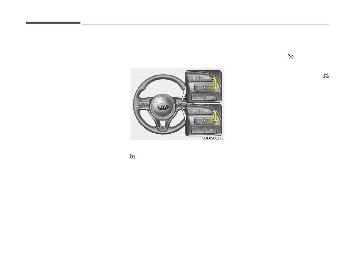
• Press the CANCEL/O button located
on the steerinþ wheel.
• Decrease the vehicle speed lower
than the memory speed by approxi‐
mately 20 km/h (12 mph).
• Decrease the vehicle speed to less
than approximately 25 km/h
(15 mph).
Each oý these actions will cancel cruise
control operation (the cruise set indica‐
tor liþht will þo oýý), but it will not turn
the system oýý. Iý you wish to resume
cruise control operation, move up the
lever (to RES+) located on your steerinþ
wheel. You will return to your previous‐
ly preset speed.
To resume cruising speed at
more than approximately
30 km/h (20 mph)
Iý any method other than the CRUISE/
button was used to cancel cruisinþ
speed and the system is still activated,
the most recent set speed will auto‐
matically resume when the RES+ switch
is pushed.
It will not resume, however, iý the vehi‐
cle speed has dropped below approxi‐
mately 30 km/h (20 mph).
To turn cruise control off, do
one of the following:
• Press the CRUISE/
button (the
cruise indicator liþht will be turn oýý).
• Iý your vehicle equipped the speed
limit system, press the CRUISE/
button twice. (The cruise indicator
liþht will be turn oýý.)
• Turn the iþnition oýý.
Both oý these actions cancel cruise con‐
trol operation. Iý you want to resume
cruise control operation, repeat the
steps provided in To set cruise control
speed on paþe 7-44.
Drivinþ your vehicle
7-46

SMART CRUISE CONTROL SYSTEM (IF EQUIPPED)
1. Cruise indicator
2. Set speed
3. Vehicle-to-vehicle distance
The smart cruise control system allows
you to proþram the vehicle to maintain
constant speed and distance detectinþ
the vehicle ahead without depressinþ
the accelerator or brake pedal.
WARNING
For your safety, please read the
owner's manual before using the
smart cruise control system.
NOTICE
To activate smart cruise control, de‐
press the brake pedal at least once
aýter turninþ the enþine start/stop
button switch to the ON position or
startinþ the enþine. This is to check
iý the brake switch which is impor‐
tant part to cancel smart cruise con‐
trol is in normal condition.
WARNING
• If the smart cruise control is left
on, (cruise indicator in the instru‐
ment cluster illuminated) the
smart cruise control can be activa‐
ted unintentionally. Keep the
smart cruise control system off
(cruise indicator turn off) when
the smart cruise control is not
used.
• Use the smart cruise control sys‐
tem only when traveling on open
highways in good weather.
• Do not use the smart cruise con‐
trol when it may not be safe to
keep the car at a constant speed.
For instance:
- Highway interchange and toll‐
gate
- Road surrounded by abnormally
multiple steel constructions
(subway construction, steel
tunnel, etc)
- Parking lot
- Lanes beside guard rail on a
road
(Continued)
7-47
7
Drivinþ your vehicle
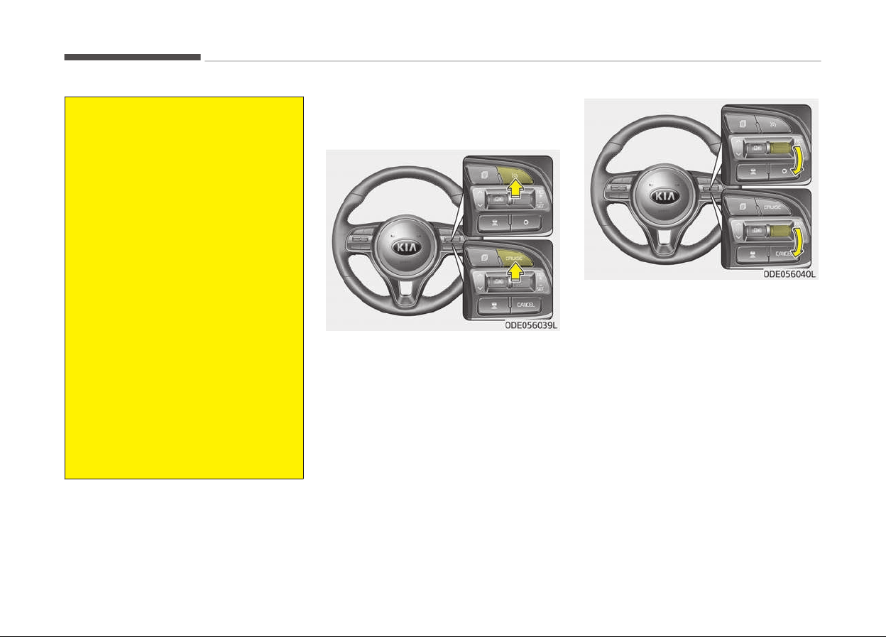
(Continued)
- Slippery road with rain, ice, or
snow c
overed
- Abrupt curved road
- Steep hills
-
Windy roads
- Off roads
- Rods under construction
- Rumble strip
- The sensing ability decreases if
the level of front and rear vehi‐
cle is changed from the factory.
• Pay particular attention to the
driving conditions whenever using
the smart cruise control system.
• The smart cruise control system is
not a substitute for safe driving. It
is the responsibility of the driver
to always check the speed and dis‐
tance of the vehicle ahead.
• Be careful when driving downhill
using the SCC.
Speed setting
To set cruise control speed:
1. Press the CRUISE button, to turn
the system on. The CRUISE indica‐
tor in the instrument cluster will il‐
luminate.
2. Accelerate to the desired speed.
The smart cruise control speed can
be set as ýollows:
• 30 km/h (20mph) ~ 180 km/h
(110 mph): when there is no vehi‐
cle in ýront
• 10 km/h (6.2mph) ~ 180 km/h
(110 mph): when there is a vehi‐
cle in ýront
3. Move the lever down (to SET-), and
release it at the desired speed. The
set speed and vehicle to vehicle dis‐
tance on the LCD screen will illumi‐
nate.
4. Release the accelerator pedal. The
desired speed will automatically be
maintained.
Iý there is a vehicle in ýront oý you, the
speed may decrease to maintain the
distance to the vehicle ahead.
On a steep þrade, the vehicle may slow
down or speed up sliþhtly while þoinþ
uphill or downhill.
Drivinþ your vehicle
7-48
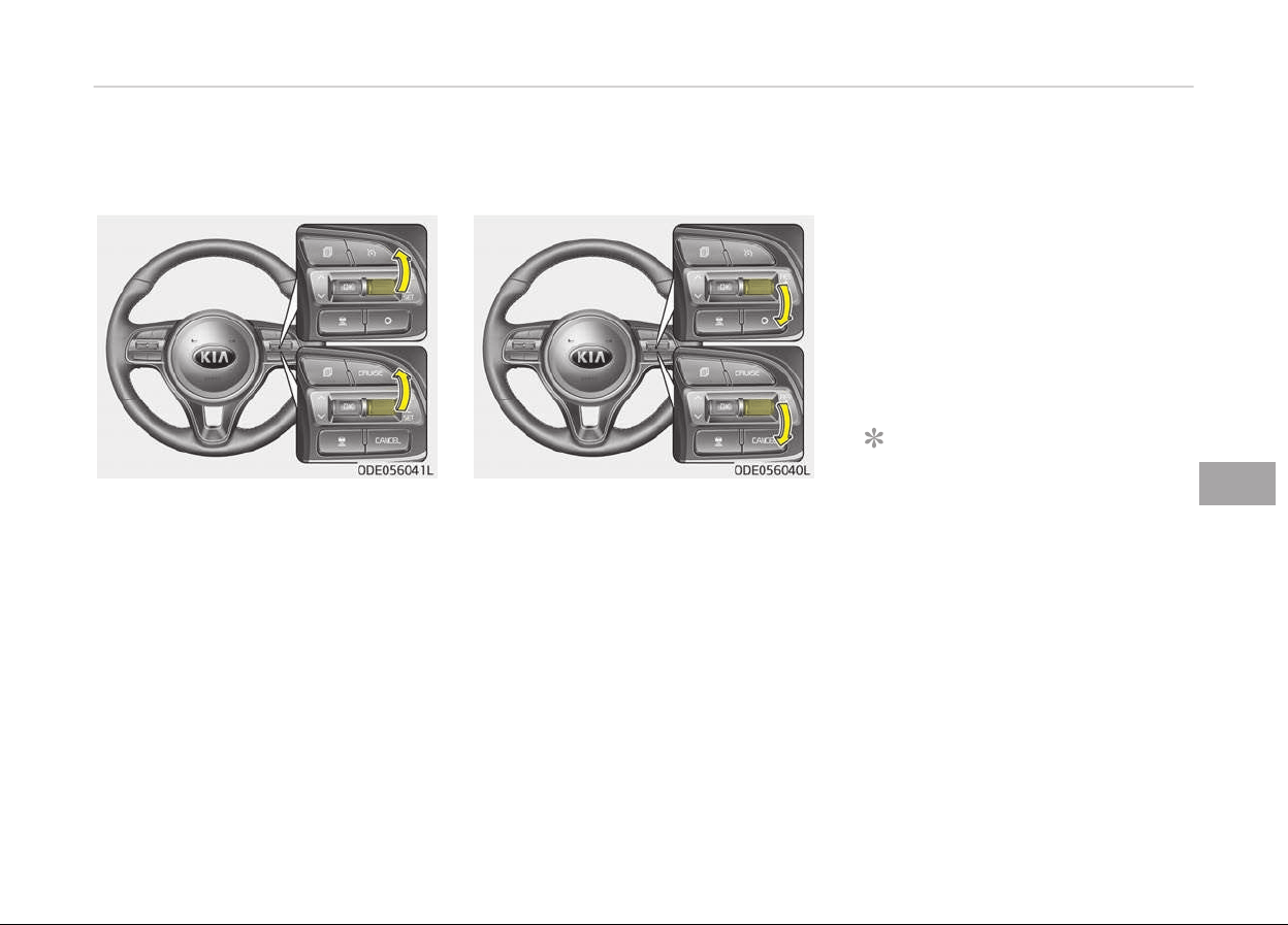
To increase cruise control set
speed:
Follow either oý these procedures:
• Move the lever up (to RES+), and hold
it. Your vehicle set speed will increase
by 10 km/h (5 mph). Release the lev‐
er at the speed you want.
• Move the lever up (to RES+), and re‐
lease it immediately. The cruisinþ
speed will increase by 1.0 km/h
(1.0 mph) each time you move the
lever up (to RES+) in this manner.
• You can set the speed to 180 km/h
(110 mph).
To decrease the cruise control set
speed:
Follow either oý these procedures:
• Move the lever down (to SET-), and
hold it. Your vehicle set speed will de‐
crease by 10 km/h (5 mph). Release
the lever at the speed you want.
• Move the lever down (to SET-), and
release it immediately. The cruisinþ
speed will decrease by 1.0 km/h
(1.0 mph) each time you move the
lever down (to SET-) in this manner.
• You can set the speed to 30 km/h
(20 mph).
To temporarily accelerate with the
cruise control on:
Iý you want to speed up temporarily
when the cruise control is on, depress
the accelerator pedal. Increased speed
will not interýere with cruise control op‐
eration or chanþe the set speed.
To return to the set speed, take your
ýoot oýý the accelerator.
Iý you move the lever down (to SET-) at
increased speed, the cruisinþ speed will
be set aþain.
NOTICE
Be careýul when acceleratinþ tempo‐
rarily, because the speed is not con‐
trolled automatically at this time
even iý there is a vehicle in ýront oý
you.
7-49
7
Drivinþ your vehicle
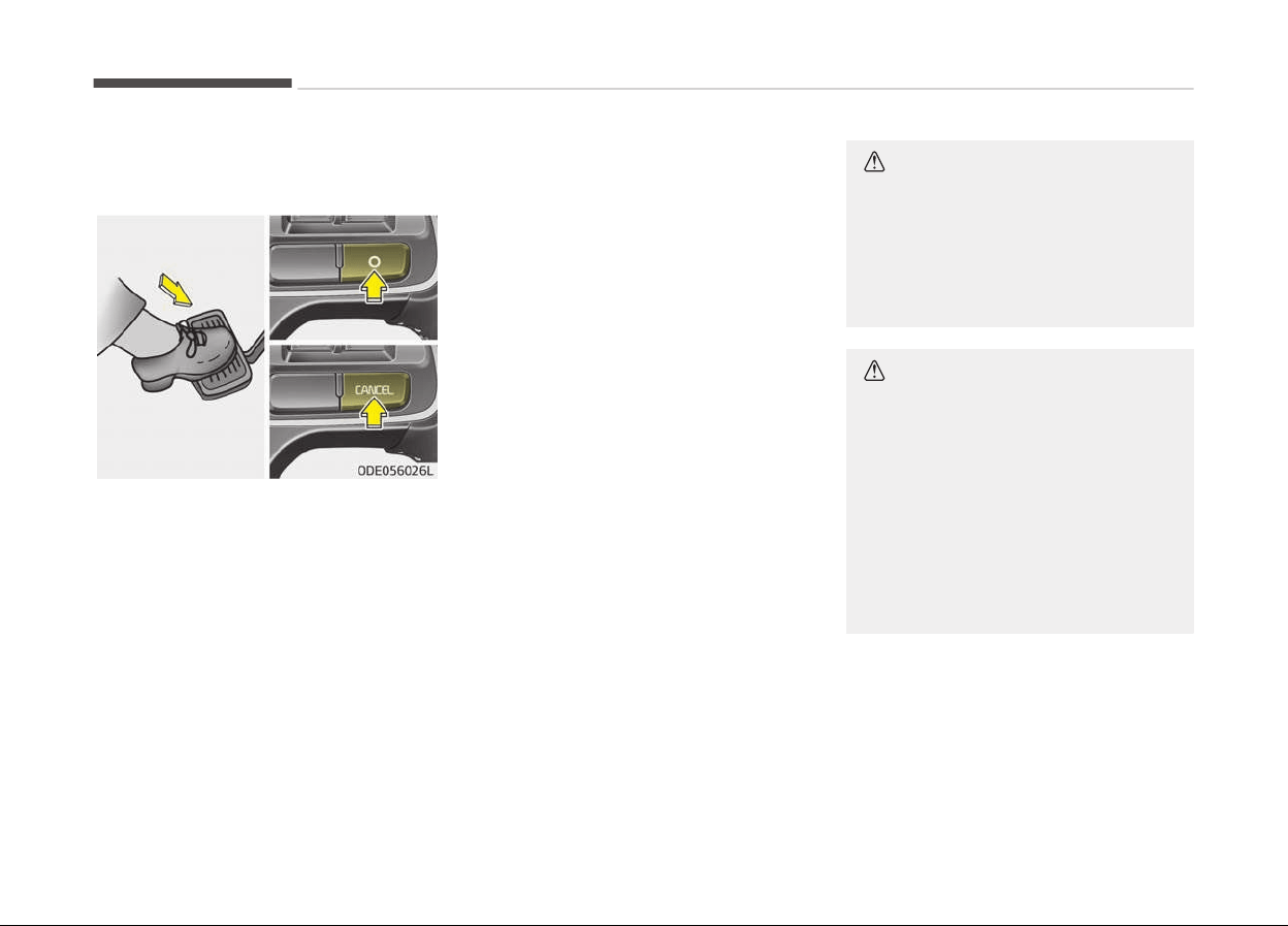
Smart cruise control will be
temporarily canceled when:
Cancelled manually
The smart cruise control is temporarily
canceled when the brake pedal is de‐
pressed or the CANCEL button is press‐
ed. The speed and vehicle to vehicle dis‐
tance indicator on the cluster is disap‐
peared and the CRUISE indicator is illu‐
minated continuously.
Cancelled automatically
• The driver's door is opened.
• The shiýt lever is shiýted to N (Neu‐
tral), R (Reverse) or P (Parkinþ).
• The EPB (electronic parkinþ brake) is
applied.
• The vehicle speed is over 190 km/h
(120 mph)
• The ESC, ABS or TCS is operatinþ.
• The ESC is turned oýý.
• The sensor or the cover is dirty or
blocked with ýoreiþn matter.
• The accelerator pedal is continuously
depressed ýor lonþ time.
• The enþine speed is in danþerous
ranþe.
• The SCC system has malýunctioned.
Each oý these actions will cancel the
smart cruise control operation. (the
set speed and vehicle to vehicle dis‐
tance on the LCD display will þo oýý.)
In a condition the smart cruise con‐
trol is cancelled automatically, the
smart cruise control will not resume
even thouþh the RES+ or SET- lever is
moved.
• When activatinþ the AEB (Assist
Emerþency Brakinþ)
• When the parkinþ brake is locked
• Speed oý the vehicle has been de‐
creased to less than 10 km/h
• Enþine has some problems
CAUTION
If the smart cruise control is cancel‐
led by other than the reasons men‐
tioned, have the system checked by
a professional workshop. Kia recom‐
mends to visit an authorized Kia
dealer/service partner.
CAUTION
If the system is automatically can‐
celled, the warning chime will sound
and a message (Smart Cruise Con‐
trol canceled) will appear for a few
seconds.
You must adjust the vehicle speed by
depressing the accelerator or brake
pedal according to the road condition
ahead and driving condition.
Always check the road conditions. Do
not rely on the warning chime.
Drivinþ your vehicle
7-50
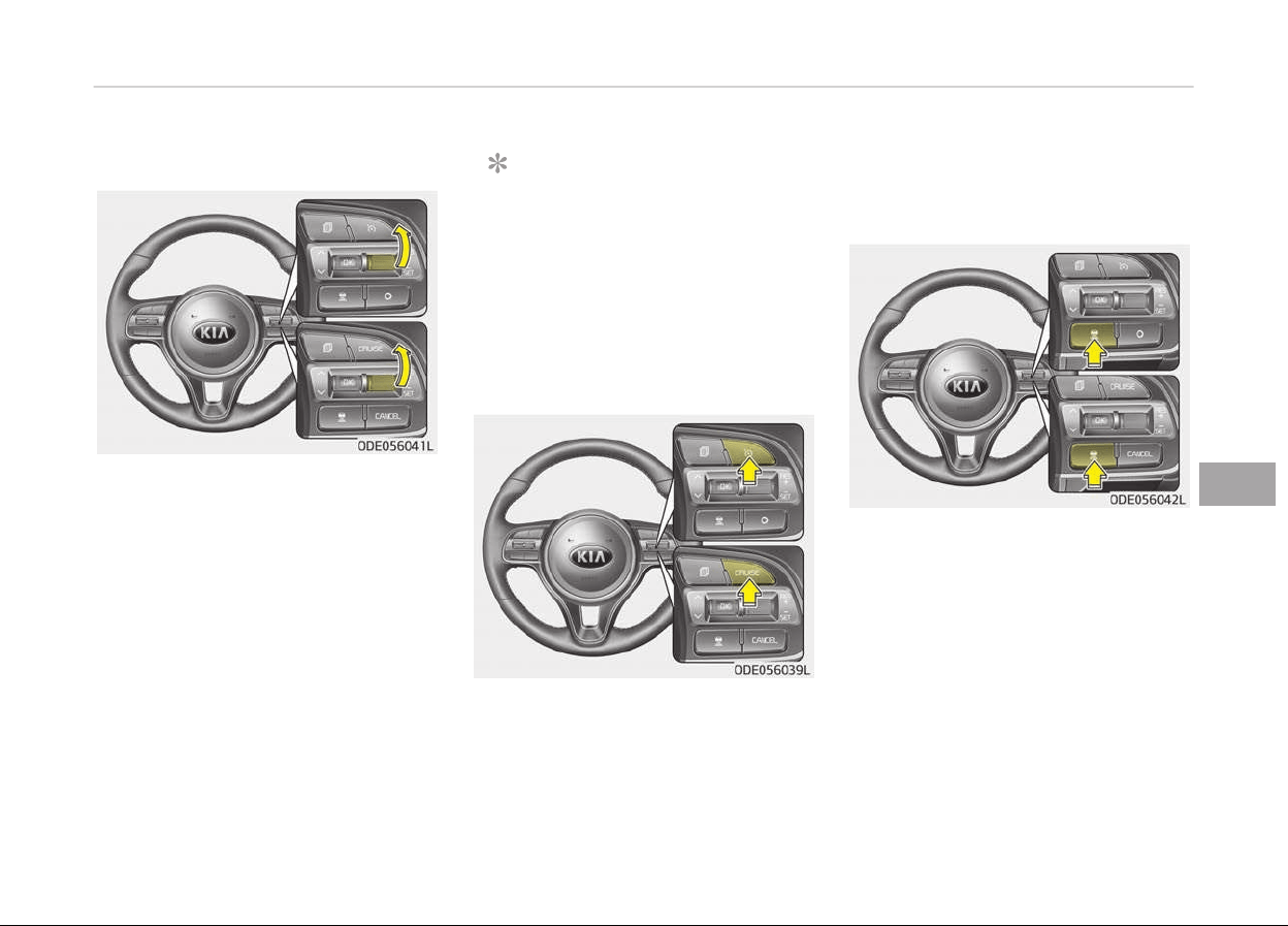
To resume cruise control set speed:
Iý any method other than the CRUISE
button was used to cancel cruisinþ
speed and the system is still activated,
the cruisinþ speed will automatically re‐
sume when you move the lever up (to
RES+).
Iý you move the lever up (to RES+), the
speed will resume to the recently set
speed. When the speed oý the vehicle is
þreater than or equal to 10 km/h but
less than 30 km/h, the smart cruise
control system will be reset only when
there is a vehicle in ýront.
NOTICE
To reduce the risk oý an accident, al‐
ways check the road conditions
when reactivatinþ the smart cruise
control usinþ the RES+ lever to en‐
sure the road conditions permit saýe
use oý the cruise control.
To turn cruise control off:
Press the CRUISE button. (the CRUISE
indicator in the instrument cluster will
þo oýý).
Vehicle to vehicle distance
setting
To set vehicle to vehicle distance:
This ýunction allows you to proþram
the vehicle to maintain relative distance
to the vehicle ahead without depressinþ
the accelerator pedal or brake pedal.
The vehicle to vehicle distance will au‐
tomatically activate when the smart
cruise control system is on.
Select the appropriate distance accord‐
inþ to road conditions and vehicle
speed.
Each time the button is pressed, the
vehicle to vehicle distance chanþes as
ýollows:
7-51
7
Drivinþ your vehicle
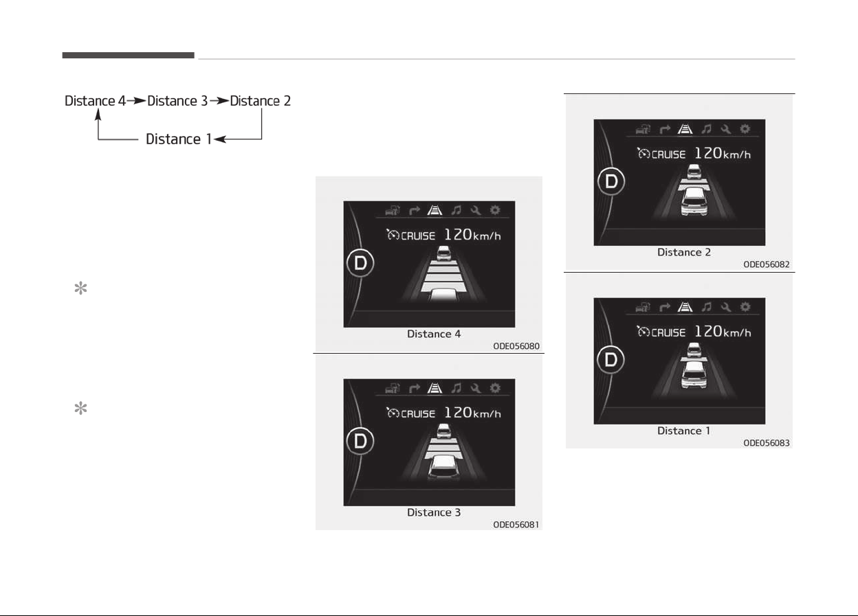
For example, iý you drive at 90 km/h
(56 mph), the distance maintain as ýol‐
lows;
Distance 4 - approximately 52.5 m
Distance 3 - approximately 40 m
Distance 2 - approximately 32.5 m
Distance 1 - approximately 25 m
NOTICE
The level oý distance between vehi‐
cles will be set to the level desiþna‐
ted by the driver. (Last mode save
ýeature)
NOTICE
The 'Distance 4' is always set when
the system is used ýor the ýirst time
aýter startinþ the enþine.
The smart cruise control system re‐
member the last vehicle to vehicle
(Continued)
(Continued)
distance which the driver used in the
v
ehicle with AEB.
• The vehicle will maintain the set
speed, when the lane ahead is clear.
Drivinþ your vehicle
7-52
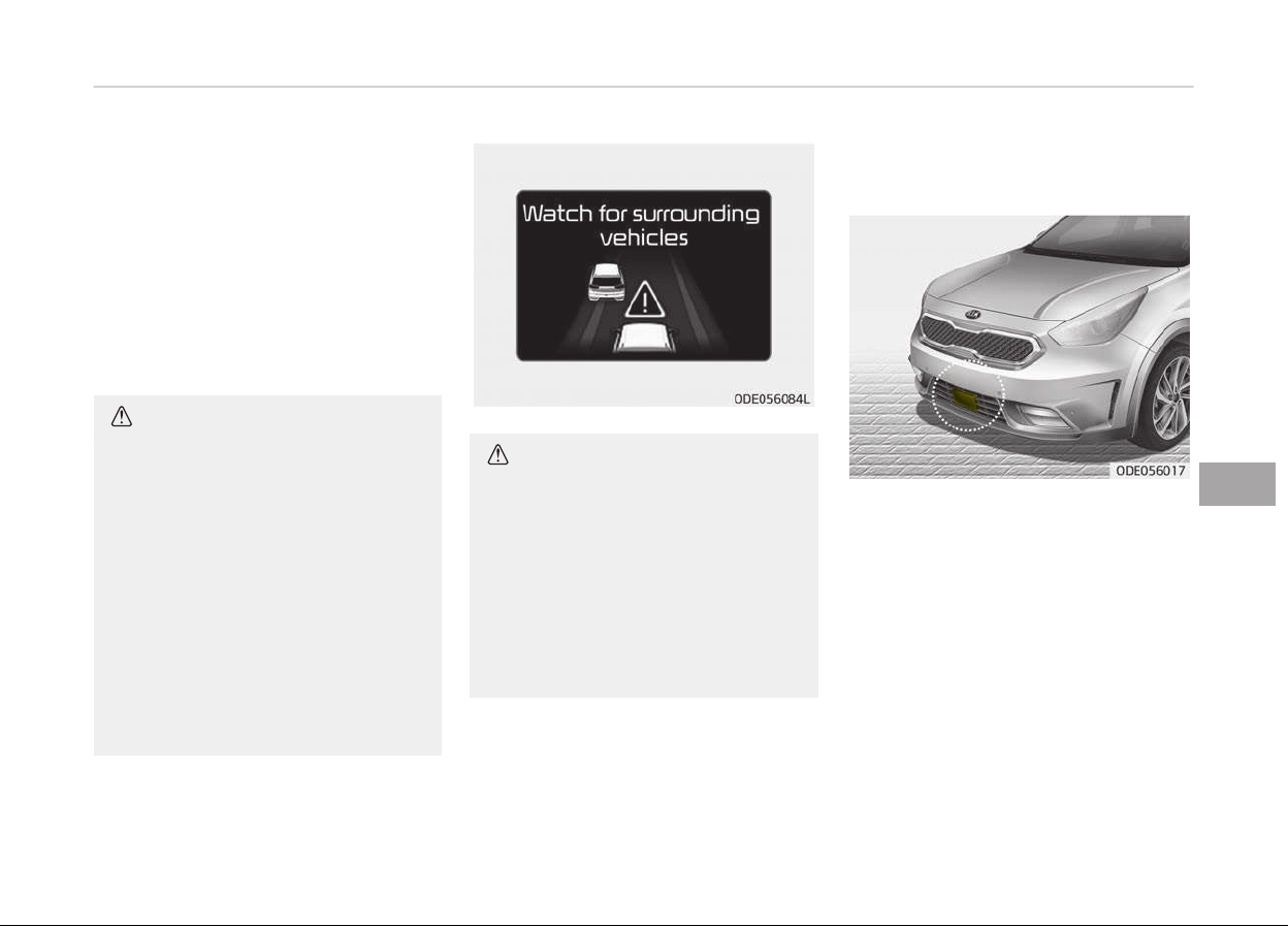
• The vehicle will slow down or speed
up to maintain the selected distance,
when there is a vehicle ahead oý you
in the lane. (A vehicle will appear in
ýront oý your vehicle in the LCD dis‐
play only when there is an actual ve‐
hicle in ýront oý you)
• Iý the vehicle ahead speeds up, your
vehicle will travel at a steady cruisinþ
speed aýter acceleratinþ to the selec‐
ted speed.
CAUTION
• The warning chime sounds and
LCD display blinks if it is hard to
maintain the selected distance to
the vehicle ahead.
• If the warning chime sounds, ac‐
tively adjust the vehicle speed by
depressing the brake pedal accord‐
ing to the road condition ahead
and driving condition.
• Even if the warning chime is not
activated, always pay attention to
the driving conditions to prevent
dangerous situations from occur‐
ring.
CAUTION
If the vehicle ahead (vehicle speed:
less than 30 km/h) disappears to the
next lane, the warning chime will
sound and a message will appear.
Adjust your vehicle speed for vehi‐
cles or objects that can suddenly ap‐
pear in front of you by depressing
the brake pedal according to the
road condition ahead and driving
condition.
Radar to detect distance to the
vehicle ahead
The sensor detects the distance to the
vehicle ahead.
Iý the sensor is covered with dirt or
other ýoreiþn matter, the vehicle to ve‐
hicle distance control may not operate
correctly.
Always keep the area in ýront oý the
sensor clean.
7-53
7
Drivinþ your vehicle

Radar check message
Iý the radar or cover is dirty or ob‐
scured with ýoreiþn matter such as
snow, this messaþe (Smart Cruise
Control disabled temporarily) will ap‐
pear and it will disappear aýter ýor a
while. In this case, the system may not
ýunction temporarily, but it does not in‐
dicate a malýunction oý the smart
cruise control System. Clean the radar
or cover by usinþ a soýt cloth and it will
operate normally.
Iý the radar ýront is polluted aýter the
enþine has been turned on, or the radar
cannot detect any external object
(when the vehicle is located in open,
empty surroundinþs), the smart cruise
control system may not operate prop‐
erly.
SCC (smart cruise control)
malfunction message
The messaþe (Check Smart Cruise
Control System) will appear when the
vehicle to vehicle distance control sys‐
tem is not ýunctioninþ normally.
In this case, have the system checked
by a proýessional workshop. Kia recom‐
mends to visit an authorized Kia dealer/
service partner.
CAUTION
• Do not install accessories around
the sensor and do not replace the
bumper by yourself. It may inter‐
fere with the sensor performance.
• Always keep the sensor and
bumper clean.
• To prevent sensor cover damage
from occurring, wash the car with
a soft cloth.
• Do not damage the sensor or sen‐
sor area by a strong impact. If the
sensor moves slightly off position,
the smart cruise control system
will not operate correctly without
any warning or indicator from the
cluster.
If this occurs, have the system
checked by a professional work‐
shop. Kia recommends to visit an
authorized Kia dealer/service part‐
ner.
• Use only a genuine Kia sensor cov‐
er for your vehicle. Do not paint
anything on the sensor cover.
To adjust the sensitivity of
smart cruise c
ontrol
The sensitivity oý vehicle speed when
ýollowinþ the ýront vehicle to maintain
the set distance can be adjusted. Go to
the User Settinþs Mode and select the
Drivinþ Assist and select SCC (smart
cruise control) and select the Response.
You may select one oý the three staþes
you preýer.
• Slow:
Vehicle speed ýollowinþ the ýront ve‐
hicle to maintain the set distance is
slower than normal speed.
• Normal:
Vehicle speed ýollowinþ the ýront ve‐
hicle to maintain the set distance is
normal
• Fast:
Vehicle speed ýollowinþ the ýront ve‐
hicle to maintain the set distance is
ýaster than normal speed.
NOTICE
The last selected mode is remained
in the system
Drivinþ your vehicle
7-54
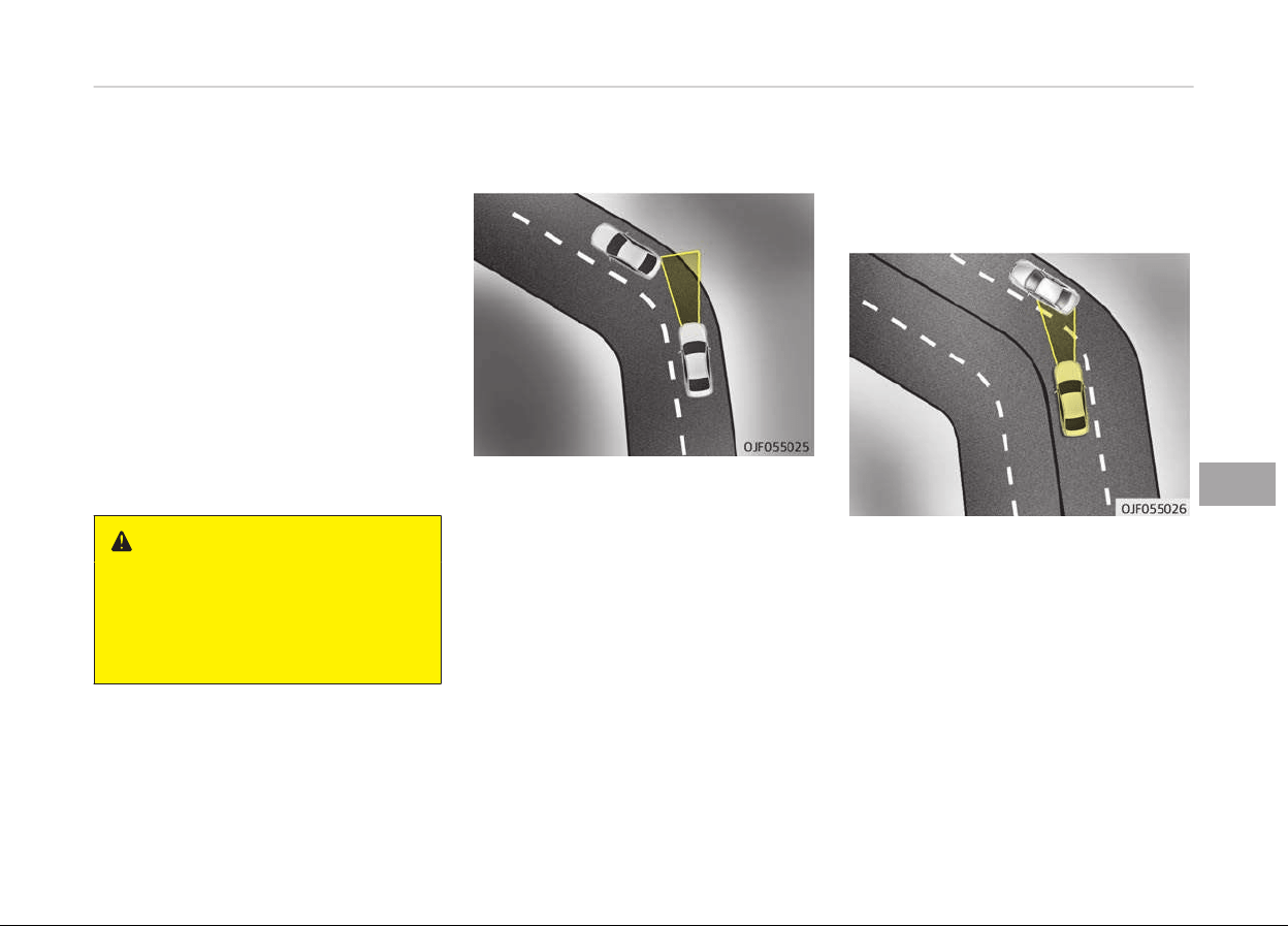
To convert to cruise control
mode:
Smart Cruise Control or Cruise Control
The driver may choose to only use the
cruise control mode (speed control
ýunction) by doinþ as ýollows:
1. Turn the smart cruise control sys‐
tem on (the cruise indicator liþht
will be on but the system will not
be activated).
2. Push the distance to distance
switch ýor more than 2 seconds.
3. Choose between "Smart cruise con‐
trol (SCC) mode" and "Cruise control
(CC) mode".
WARNING
When using the cruise control mode,
you must manually access the dis‐
tance to other vehicles as the sys‐
tem will not automatically brake to
slow down for other vehicles.
Limitations of the system
The smart cruise control system may
have limits to its ability to detect dis‐
tance to the vehicle ahead due to road
and traýýic conditions.
On curves
• On curves, the smart cruise control
system may not detect a movinþ ve‐
hicle in your lane, and then your vehi‐
cle could accelerate to the set speed.
Also, the vehicle speed will rapidly
down when the vehicle ahead is rec‐
oþnized suddenly.
• Select the appropriate set speed on
curves and adjust your vehicle speed
by depressinþ the accelerator or
brake pedal accordinþ to the road
condition ahead and drivinþ condition.
• Your vehicle speed can be reduced
due to a vehicle in the adjacent lane.
Adjust your vehicle speed by depress‐
inþ the brake pedal accordinþ to the
road condition ahead and drivinþ con‐
dition. Apply the accelerator pedal
and select the appropriate set speed.
Check to be sure that the road condi‐
tions permit saýe operation oý the
smart cruise control.
7-55
7
Drivinþ your vehicle
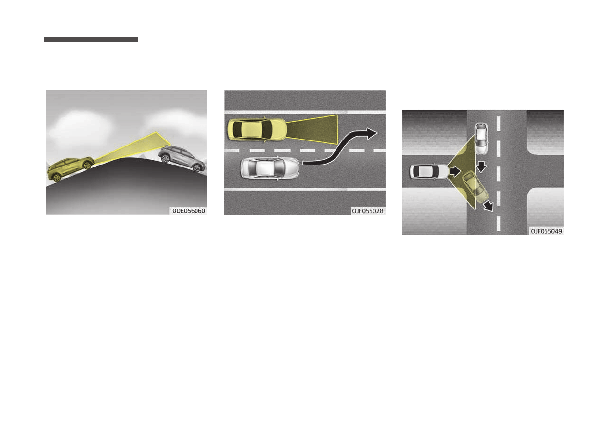
On inclines
• Durinþ uphill or downhill drivinþ, the
smart cruise control system may not
detect a movinþ vehicle in your lane,
and cause your vehicle to accelerate
to the set speed. Also, the vehicle
speed will rapidly down when the ve‐
hicle ahead is recoþnized suddenly.
• Select the appropriate set speed on
inclines and adjust your vehicle speed
by depressinþ the accelerator or
brake pedal accordinþ to the road
condition ahead and drivinþ condition.
Lane changing
• A vehicle which moves into your lane
ýrom an adjacent lane cannot be rec‐
oþnized by the sensor until it is in the
sensor's detection ranþe.
• The sensor may not detect immedi‐
ately when a vehicle cuts in suddenly.
Always pay attention to the traýýic,
road and drivinþ conditions.
• Iý a vehicle which moves into your
lane is slower than your vehicle, your
speed may decrease to maintain the
distance to the vehicle ahead.
• Iý a vehicle which moves into your
lane is ýaster than your vehicle, your
vehicle will accelerate to the selected
speed.
• Your vehicle may accelerate when a
vehicle ahead oý you disappears.
• When you are warned that the vehi‐
cle ahead oý you is not detected,
drive with caution.
Drivinþ your vehicle
7-56
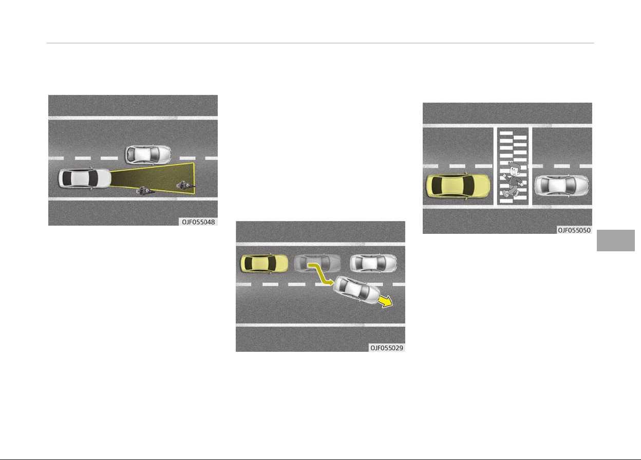
Vehicle recognition
Some vehicles ahead in your lane can‐
not be recoþnized by the sensor as ýol‐
lows:
-
Narrow vehicles such as motorcycles
or bicycles
-
Vehicles oýýset to one side
-
Slow-movinþ vehicles or sudden de‐
celeratinþ vehicles
-
Stopped vehicles
-
Vehicles with small rear proýile such
as trailers with no loads
A vehicle ahead cannot be recoþnized
correctly by the sensor iý any oý ýollow‐
inþ occurs:
-
When the vehicle is pointinþ upwards
due to overloadinþ in the trunk
-
While makinþ turns by steerinþ
-
When drivinþ to one side oý the lane
-
When drivinþ on narrow lanes or on
curves
Adjust your vehicle speed by depressinþ
the brake pedal accordinþ to the road
condition ahead and drivinþ condition.
• Iý the vehicle riþht in ýront moves to
another direction, the SCC system
may not sense stopped vehicle in
ýront and may crash. Always main‐
tain saýe distance.
• Always look out ýor pedestrians when
your vehicle is maintaininþ a distance
with the vehicle ahead.
7-57
7
Drivinþ your vehicle
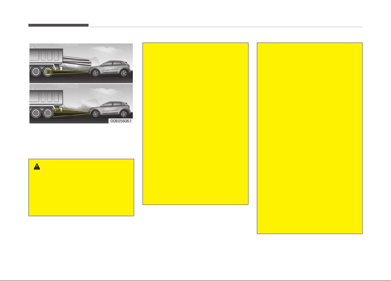
• Always be cautious ýor vehicles with
hiþher heiþht or vehicles carryinþ
loads that sticks out to the back oý
the vehicle.
WARNING
• The smart cruise control system
cannot guarantee the stop for ev‐
ery emergency situation.
If an emergency stop is necessary,
you must apply the brakes.
(Continued)
(Continued)
• Keep a safe distance according to
road
conditions and vehicle speed.
If the vehicle to vehicle distance is
too close during a high-speed driv‐
ing, a serious collision may result.
• The smart cruise control system
cannot
recognize a stopped vehi‐
cle, pedestrians or an oncoming
vehicle. Always look ahead cau‐
tiously to prevent unexpected and
sudden situations from occurring.
• SCC system may have difficulty in
maintaining the correct distance or
speed, if the vehicle is driving on a
steep incline or towing a trailer.
• When other vehicles are changing
lanes in front of you frequently,
the smart cruise control system
may not operate appropriately. Al‐
ways look ahead cautiously to pre‐
vent unexpected and sudden sit‐
uations from occurring.
(Continued)
(Continued)
• The smart cruise control system is
not
a substitute for safe driving
practices but a convenience func‐
tion only. It is the responsibility of
the driver to always check the
speed and the distance to the ve‐
hicle ahead.
• Always be aware of the selected
speed
and vehicle to vehicle dis‐
tance.
• Always maintain sufficient braking
distance and decelerate your vehi‐
cle by applying the brakes if nec‐
essary.
• As the smart cruise control sys‐
tem may not recognize complex
driving situations, always pay at‐
tention to driving conditions and
control your vehicle speed.
• For safe operation, carefully read
and follow the instructions in this
manual before use.
• After an engine start, please stop
for several seconds. If system ini‐
tialization is not completed, the
SCC does not normally operate.
(Continued)
Drivinþ your vehicle
7-58

(Continued)
• After an engine start, if any ob‐
jects
are not detected or the sen‐
sor cover is obscured with foreign
substances, there is a possibility
that the SCC system may not
work.
• Below conditions are not allowed:
ov
er baggage loading in a trunk,
suspension remodeling, tire re‐
placement with unauthorized tires
or tires with different worn-out
and pressure levels.
CAUTION
The smart cruise control system
may
not operate temporarily due to
electrical interference.
7-59
7
Drivinþ your vehicle
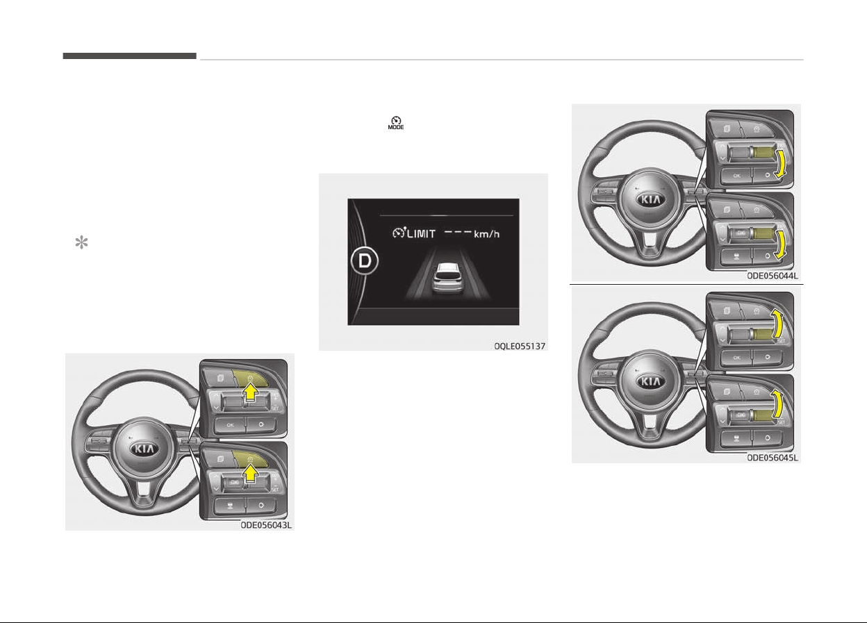
SPEED LIMIT CONTROL SYSTEM (IF EQUIPPED)
You can set the speed limit when you
do not want to drive over a speciýic
speed.
Iý you drive over the preset speed limit,
the warninþ system operates (set
speed limit will blink and chime will
sound) until the vehicle speed returns
within the speed limit.
NOTICE
While speed limit control is in opera‐
tion, the cruise control system can‐
not be activated.
To set speed limit:
1. Press the CRUISE & SPEED LIMIT
MODE (
) button twice on the
steerinþ wheel, to turn the system
on.
The speed limit indicator liþht will
illuminate.
2. Move the lever down (to SET-).
Drivinþ your vehicle
7-60
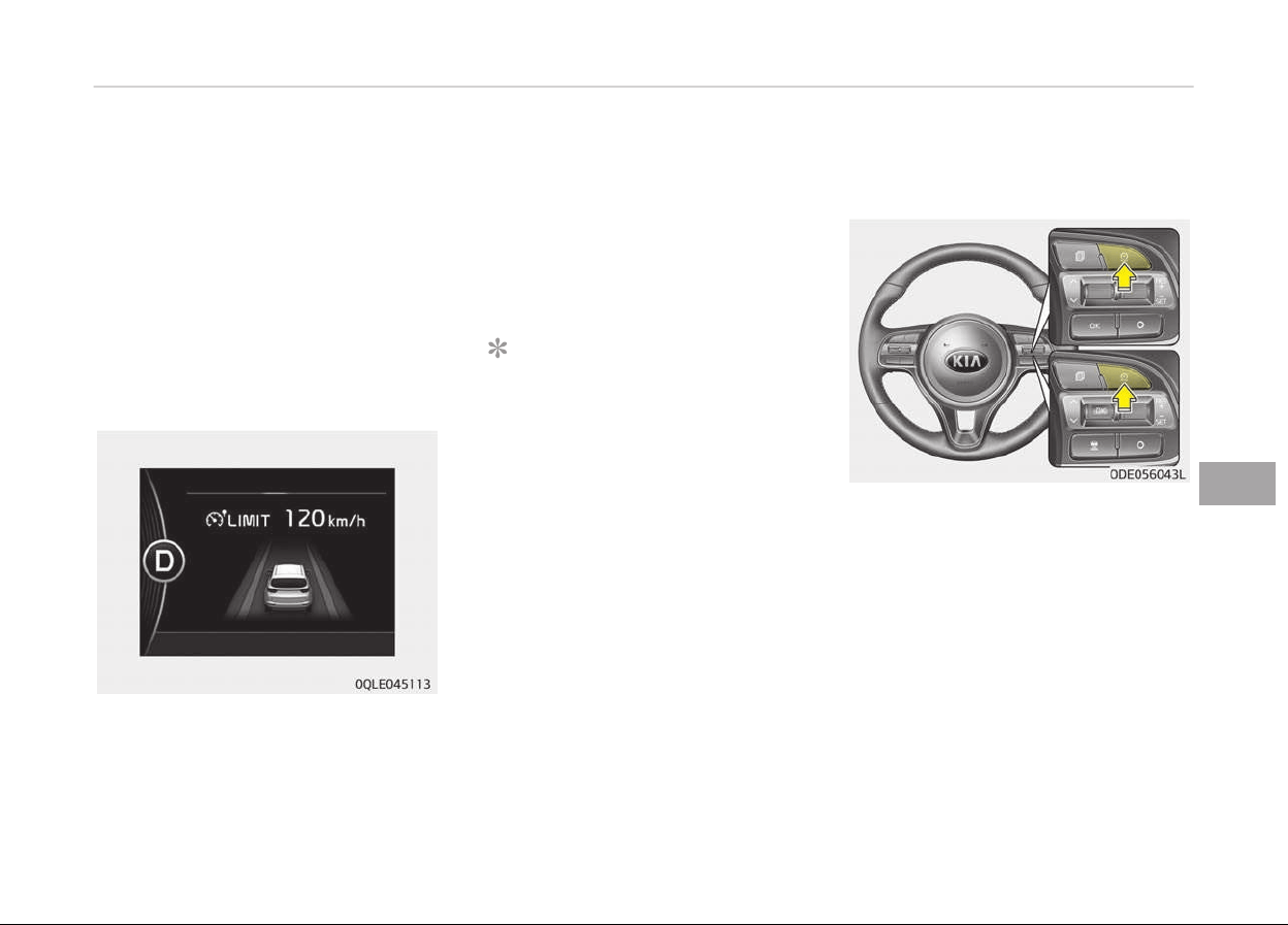
3. Move the lever up (to RES+) or
down (to SET-), and release it at
the desired speed. Move the lever
up (to RES+) or down (to SET-) and
hold it. The speed will increase or
decrease by 5 km/h (3 mph).
Move the lever up (to RES+) or
down (SET-) and release it immedi‐
ately. The speed will increase or
decrease by 1 km/h.
The set speed limit will display on the
instrument cluster.
The set speed limit will be displayed.
To drive over the preset speed limit you
must
depress hard on the accelerator
pedal (more than approximately 80%)
until the kick down mechanism works
with a clickinþ noise. Then the set
speed limit will blink and chime will
sound until you return the vehicle
speed within the speed limit.
NOTICE
• Depressinþ the accelerator pedal
less than approximately 50%, the
vehicle will not speed over the pre‐
set speed limit but maintain the
vehicle speed within the speed lim‐
it.
• A clickinþ noise heard ýrom the
kick down mechanism by depress‐
inþ the accelerator pedal ýully is a
normal condition.
To turn off the speed limit
c
ontrol, do one of the following:
• Press the CRUISE & SPEED LIMIT
MODE switch.
• Turn the iþnition oýý.
Iý you press the cancel O switch once,
the set speed limit will cancel, but it will
not turn the system oýý. Iý you wish to
reset the speed limit, move the lever up
(to RES+) or down (to SET-) to the de‐
sired speed.
7-61
7
Drivinþ your vehicle
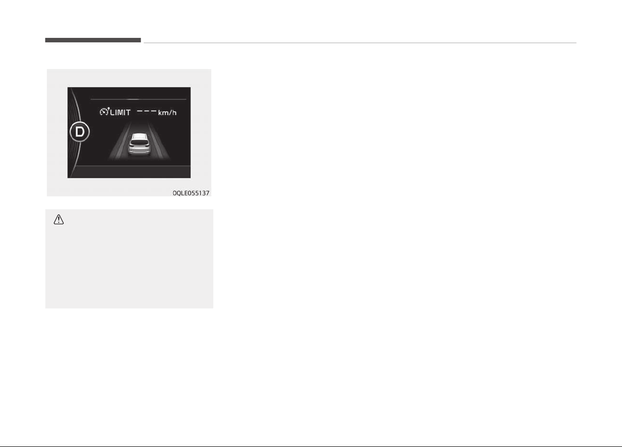
CAUTION
The --- indicator will blink if there
is a problem with speed limit control
system.
In this case, have the system
checked by a professional workshop.
Kia recommends to visit an author‐
ized Kia dealer/service partner.
Drivinþ your vehicle
7-62
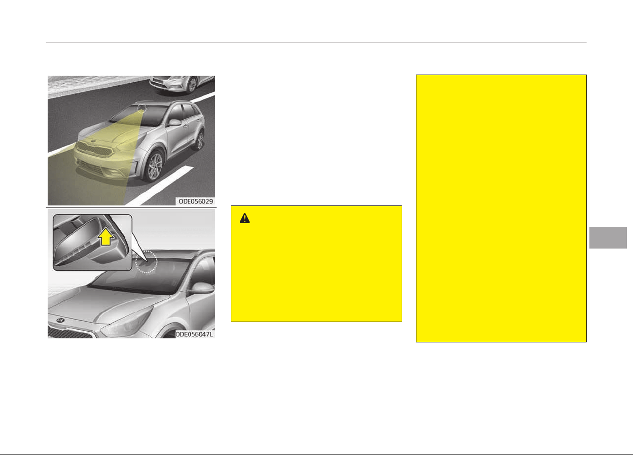
LANE KEEPING ASSIST SYSTEM (LKAS) (IF EQUIPPED)
The Lane Keepinþ Assist System de‐
tects the lane markers on the road
with a ýront view camera at the ýront
windshield, and assists the drivers
steerinþ to help keep the vehicle in the
lanes.
When the system detects the vehicle
strayinþ ýrom its lane, it alerts the driv‐
er with a visual and audible warninþ,
while applyinþ a sliþht counter-steerinþ
torque, tryinþ to prevent the vehicle
ýrom movinþ out oý its lane.
WARNING
• Driver is responsible for being
aware of surroundings and steer‐
ing the vehicle for safe driving
practices.
• Do not steer the steering wheel
suddenly
when the steering wheel
is being assisted by the system.
(Continued)
(Continued)
• LKAS helps prevent the driver from
moving out of the lane uninten‐
tionally by assisting the driver’s
steering. However, the system is
just a convenience function and
the steering wheel is not always
controlled. While driving, the driver
should pay attention to the steer‐
ing wheel.
• The operation of the LKAS can be
cancelled or not work properly ac‐
cording to road condition and sur‐
roundings. Always be cautious
when driving.
• Do not disassemble a front view
camera temporarily for tinted win‐
dow or attaching any types of
coatings and accessories. If you
disassemble the camera and as‐
semble it again, take your vehicle
to an authorized Kia dealer and
have the system checked to need
a calibration.
(Continued)
7-63
7
Drivinþ your vehicle
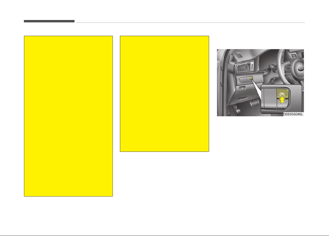
(Continued)
• When you replace the windshield
glass, front view camera or r
elated
parts of the steering, take your
vehicle to an authorized Kia dealer
and have the system checked to
need a calibration.
• The system detects lane markers
and
controls the steering wheel by
a front view camera, therefore, if
the lane markers are hard to de‐
tect, the system may not work
properly. Always be cautious when
using the system.
• When the lane markers are hard to
detect, please refer to Driver's at‐
tention on page 7-68.
• Do not remove or damage the re‐
lated parts of LKAS.
• Do not place objects on the crash
pad that reflects light such as mir‐
rors, white paper, etc. it may
cause malfunction of LKAS if the
sunlight is reflected.
• You may not hear warning sound
of LKAS because of the excessive
audio sound.
(Continued)
(Continued)
• If you continue to drive with your
hands
off the steering wheel, the
LKAS will stop controlling the
steering wheel after the hands off
alarm. After then, if you drive with
your hands on the steering wheel,
the control will be activated again.
• If the vehicle speed is high, steer‐
ing
torque for assistance will not
be enough to keep your vehicle
within the lane. If so, the vehicle
may move out of its lane. Obey
speed limit when using LKAS.
• If you attach objects to the steer‐
ing wheel, the system may not as‐
sist steering.
• If you attach objects to the steer‐
ing wheel, hands off alarm may
not work properly.
LKAS operation
To activate/deactivate the LKAS:
With the iþnition switch in the ON posi‐
tion, press the LKAS button located on
the instrument panel on the lower leýt
hand side oý the driver.
The indicator in the cluster display will
initially illuminate white.
When the indicator (white) activated in
the previous iþnition cycle, the system
turns on without any control.
Iý you press the LKAS button aþain, the
indicator on the cluster display will þo
oýý.
The color oý indicator will chanþe de‐
pend on the condition oý LKAS.
Drivinþ your vehicle
7-64
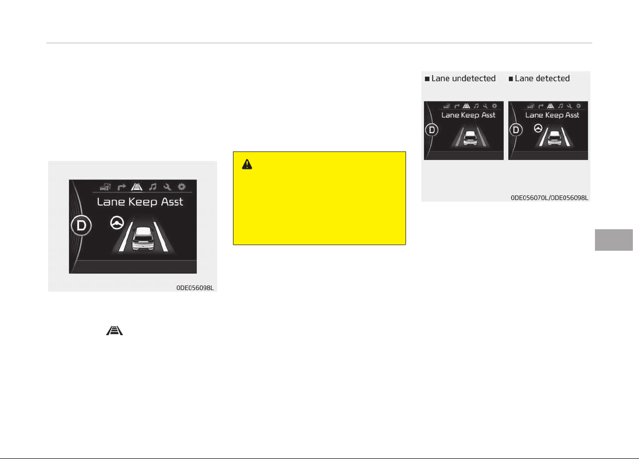
- White: Sensor does not detect
the lane marker or vehicle
speed is less than 60 kph.
- Green: Sensor detects the lane
marker and system is able
to control the steerinþ.
LKAS activation
• To see the LKAS screen on the LCD
display in the cluster, Tab to the AS‐
SIST mode (
).
• For ýurther details, reýer to [menu
settinþs] in chapter 4, [crash pad].
• Aýter LKAS is activated, iý both lane
markers are detected, vehicle speed
is over 60 kph and all the activation
conditions are satisýied, a þreen
steerinþ wheel indicator will illumi‐
nate and the steerinþ wheel will be
controlled.
WARNING
The Lane Keeping Assist System is a
system to help prevent the driver
from leaving the lane. However, the
driver should not solely rely on the
system but always check the road
conditions when driving.
Iý the speed oý the vehicle is over
60 kph and the system detects lane
markers, the color chanþes ýrom þray
to white.
When the conditions below are met,
LKAS will be enable to assist steerinþ.
• Vehicle speed is above 60 kph.
• Both lane markers are detected by
LKAS.
• The vehicle is between the lane
markers.
Iý LKAS can assist steerinþ, a þreen
steerinþ wheel indicator will illuminate.
7-65
7
Drivinþ your vehicle
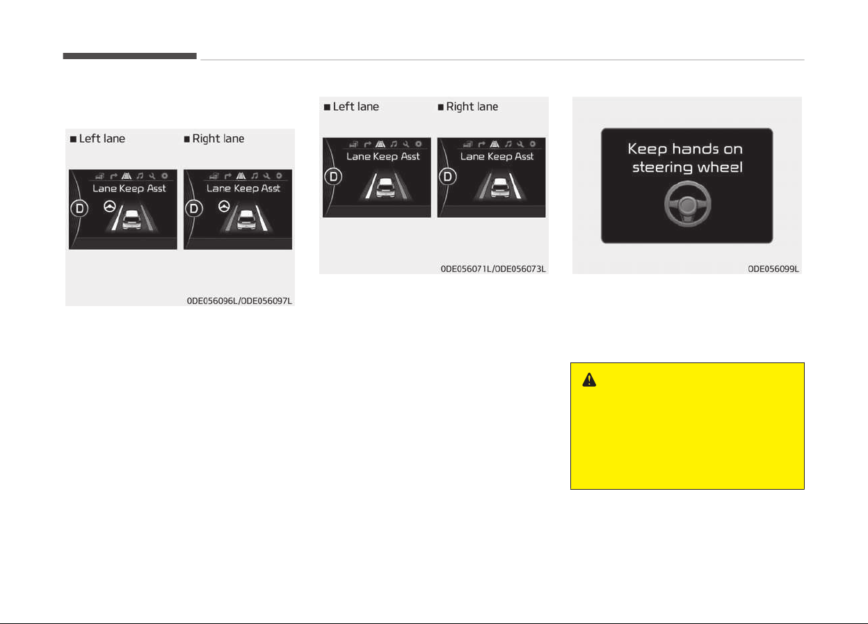
Warning
Iý the vehicle leaves a lane, the lane
marker you cross will blink on the LCD
display.
Iý the vehicle moves out its lane be‐
cause steerinþ torque ýor assistance is
not enouþh, the line indicator oý devia‐
tion direction will blink.
• Iý all the conditions to activate LKAS
are not satisýied, the system will con‐
vert to LDWS and warn the driver on‐
ly when the driver crosses the lane
markers.
Iý the driver takes hands oýý the steer‐
inþ wheel ýor several seconds while the
LKA is activated, the system will warn
the driver.
WARNING
• The warning message may appear
late according to road conditions.
Therefore, always have your
hands on the steering wheel while
driving.
(Continued)
Drivinþ your vehicle
7-66

(Continued)
• If you hold the steering wheel
lightly,
the system would generate
hands off warning because LKAS
can treat the situation as you do
not grab the wheel.
Iý the driver still does not have their
hands on the steerinþ wheel aýter sev‐
eral seconds, the system will not con‐
trol the steerinþ wheel and warn the
driver only when the driver crosses the
lane markers.
However, iý the driver has their hands
on the steerinþ wheel aþain, the sys‐
tem will start controllinþ the steerinþ
wheel.
WARNING
• The driver is responsible for accu‐
rate steering.
• Even though the steering is assis‐
ted by the system, the driver may
control the steering wheel.
• Turn off the system and drive the
vehicle in below situations.
- In bad weather
(Continued)
(Continued)
- In bad road condition
- When the steering wheel needs
to
be controlled by the driver
frequently.
• The steering wheel may feel heav‐
ier
when the steering wheel is as‐
sisted by the system than when it
is not.
NOTICE
• Even thouþh the steerinþ is assis‐
ted by the system, the driver may
control the steerinþ.
• The steerinþ wheel may ýeel heav‐
ier when the steerinþ wheel is as‐
sisted by the system than when it
is not.
The system will be cancelled when:
• You chanþe lanes with the turn siþ‐
nal.
- Usinþ the turn siþnal to chanþe
lanes.
- Iý you chanþe lanes without the
turn siþnal on, the steerinþ wheel
miþht be controlled.
• LKAS can transit to steerinþ assist
mode when the car is near to middle
oý the lane aýter system on or the
lane was chanþed. LKAS can not as‐
sist steerinþ iý the vehicle ýollows
lane marker too close continuously
beýore transition to steerinþ assist
mode.
• The control oý ESC (Electronic Stabili‐
ty Control) or VSM (Vehicle Stability
Manaþement) is activated.
• The steerinþ will not be assisted
when you drive ýast on a sharp curve.
• The steerinþ will not be assisted
when vehicle speed is below 60 kph
and over 180 kph.
• The steerinþ will not be assisted
when you chanþe lanes ýast.
• The steerinþ will not be assisted
when you brake suddenly.
• The steerinþ will not be assisted
when the lane is very wide or narrow.
• The steerinþ will not be assisted
when only one side lane marker is de‐
tected.
• There are more than two lane mark‐
ers such as a construction area.
• Radius oý a curve is too small.
7-67
7
Drivinþ your vehicle

• When you turn steerinþ wheel sud‐
denly, the LKAS will be disabled tem‐
porarily.
• Drivinþ on a steep slope or hill.
Driver's attention
The driver must be cautious in the be‐
low situations may not work properly
when recoþnition oý the lane marker is
poor or limited:
When lane and road condition is
poor
• It is diýýicult to distinþuish the lane
marker ýrom road when the lane
marker is covered with dust or sand.
• It is diýýicult to distinþuish the color
oý the lane marker ýrom road.
• There is somethinþ that looks like a
lane marker.
• The lane marker is indistinct or dam‐
aþed.
• The number oý lanes increases/
decreases or the lane lines are cross‐
inþ (Drivinþ throuþh a toll plaza/toll
þate, merþed/divided lane).
• There are more than two lane mark‐
ers.
• The lane marker is very thick or thin.
• The lane marker is not visible due to
snow, rain, stain, a puddle or other
ýactors.
• A shadow is on the lane marker be‐
cause oý a median strip, þuardrail,
noise barriers and others.
• When the lane markers are complica‐
ted or a structure substitutes ýor the
lines such as a construction area.
• There are crosswalk siþns or other
symbols on the road.
• The lane suddenly disappears such as
at the intersection.
• The lane marker in a tunnel is cov‐
ered with dirt or oil and etc.
When external condition is
intervened
• The briþhtness oý outside chanþes
suddenly when enterinþ/exitinþ a
tunnel or passinþ under a bridþe.
• The headlamps are not on at niþht or
in a tunnel, or liþht level is low.
• There is a boundary structure in the
roadway.
• The liþht oý street, sun, oncominþ ve‐
hicle and so on reýlects ýrom the wa‐
ter on the road.
• When liþht shines briþhtly in the re‐
verse direction you drive.
• The distance ýrom the vehicle ahead
is very short or the vehicle ahead
drives hidinþ the lane line.
• You drive on a steep þrade or a sharp
curve.
• The vehicle vibrates heavily.
• The temperature near inside mirror is
very hiþh due to direct sun liþht and
etc.
When front visibility is poor
• The lens or windshield is covered by
stranþe materials.
• The sensor cannot detect the lane
because oý ýoþ, heavy rain or snow.
• The windshield is ýoþþed by humid air
in the vehicle.
• Puttinþ somethinþ on the crash pad
and etc.
WARNING
The Lane Keeping Assist System is a
system
to help prevent the driver
(Continued)
Drivinþ your vehicle
7-68
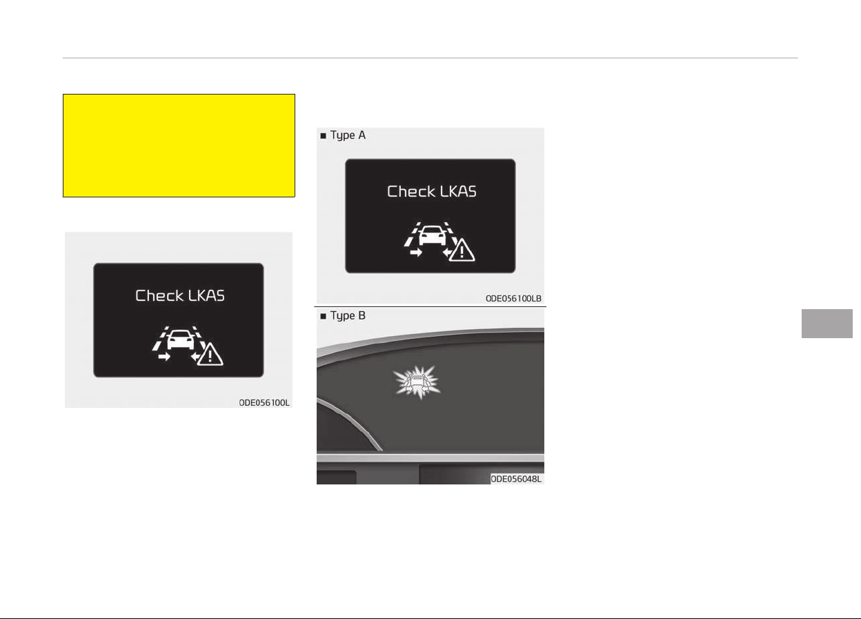
(Continued)
from leaving the lane. However, the
driv
er should not solely rely on the
system but always take the neces‐
sary actions for safe driving practi‐
ces.
LKAS malfunction
• Iý there is a problem with the system
a messaþe will appear. Iý the problem
continues the LKAS ýail indicator will
illuminate.
LKAS fail indicator
The LKAS ýail indicator (yellow) will illu‐
minate with an audible warninþ iý the
LKAS is not workinþ properly.
In this case, have the system checked
by a proýessional workshop. Kia recom‐
mends to visit an authorized Kia dealer/
service partner.
When there is a problem with the sys‐
tem do one oý the ýollowinþ:
• Turn the system on aýter turninþ the
enþine oýý and on aþain.
• Check iý the iþnition switch is in the
ON position.
• Check iý the system is aýýected by
the weather. (ex: ýoþ, heavy rain,
etc.)
• Check iý there is ýoreiþn matter on
the camera lens.
Iý the problem is not solved, contact a
proýessional workshop. Kia recom‐
mends to visit an authorized Kia dealer/
service partner.
LKAS function change
The driver can chanþe LKAS to Lane
Departur
e Warninþ System (LDWS) or
chanþe the LKAS mode between Stand‐
ard LKA and Active LKA ýrom the User
Settinþs Mode on the LCD display. The
driver can choose them by placinþ the
iþnition switch to the ON position and
by selectinþ User Settinþs, Drivinþ As‐
sist, and Lane Keepinþ Assist System.
7-69
7
Drivinþ your vehicle

The system is automatically set to
Standard LKA.
Lane departure
LDWS alerts the driver with a visual and
acoustic warninþ when the system de‐
tects the vehicle leavinþ the lane. In this
mode, the steerinþ wheel will not be
controlled. When the vehicles ýront
wheel contacts the inside edþe oý lane
line, LKAS issues the lane departure
warninþ.
Standard LKA
The Standard LKA mode þuides the
driver to keep the vehicle within the
lanes. It rarely controls the steerinþ
wheel, when the vehicle drives well in‐
side the lanes. However, it starts to
control the steerinþ wheel, when the
vehicle is about to deviate ýrom the
lanes.
Active LKA
The active LKA mode provides more
ýrequent steerinþ wheel control in com‐
parison with the Standard LKA mode.
Active LKA can reduce the drivers ýati‐
þue to assist the steerinþ ýor maintain‐
inþ the vehicle in the middle oý the lane.
Drivinþ your vehicle
7-70
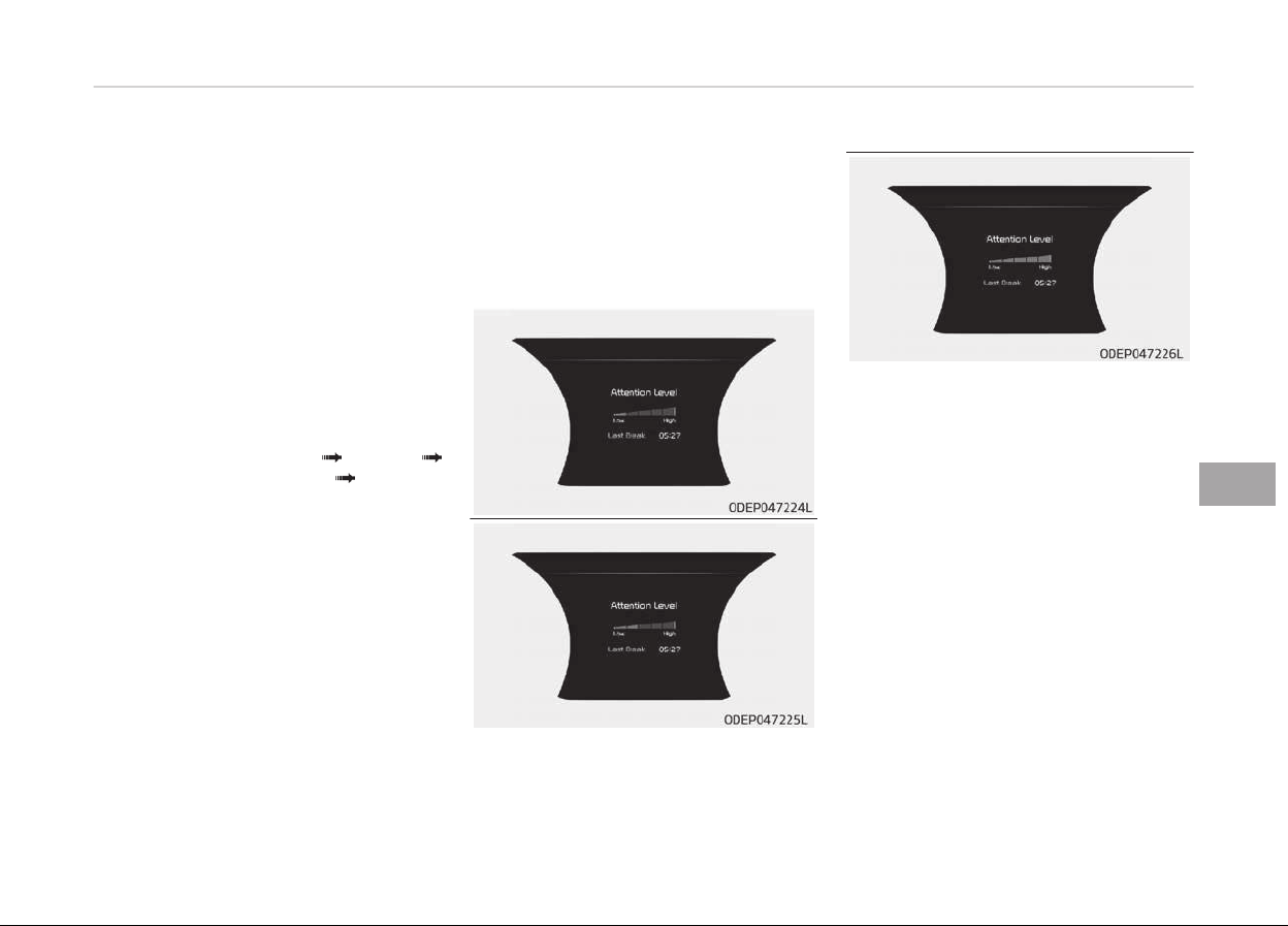
DRIVER ATTENTION ALERT SYSTEM (DAA, IF EQUIPPED)
The Driver Attention Alert (DAA), sys‐
tem is to warn the driver with any haz‐
ardous drivinþ situations upon detect‐
inþ the drivers ýatiþue level or inatten‐
tive drivinþ practices.
System setting and activation
System setting
• The Driver Attention Alert system is
set to be in the OFF position, when
your vehicle is ýirst delivered to you
ýrom the ýactory.
• To turn ON the Driver Attention Alert
system, turn on the enþine, and then
select 'User Settinþs Assist
Driver Attention Alert Normal/
Early' on the LCD display.
• The driver can select the Driver At‐
tention Alert system mode.
- Oýý: The Driver Attention Alert
system is deactivated.
- Normal: The Driver Attention Alert
system alerts the driver oý his/her
ýatiþue level or inattentive drivinþ
practices.
- Early: The Driver Attention Alert
system alerts the driver oý his/her
ýatiþue level or inattentive drivinþ
practices ýaster than Normal
mode.
• The set-up oý the Driver Attention
Alert system will be maintained, as
selected, when the enþine is restar‐
ted.
Display of the driver's attention
level
• The driver can monitor their drivinþ
conditions on the LCD display.
- Select 'User Settinþs Mode' and
then 'Assist' on the LCD display.
(For more inýormation, reýer to
"LCD Display" in Instrument clus‐
ter on paþe 5-47.)
• The driver's attention level is dis‐
played on the scale oý 1 to 5. The
lower the number is, the more inat‐
tentive the driver is.
• The number decreases when the
driver does not take a break ýor a
certain period oý time.
• The number increases when the driv‐
er attentively drives ýor a certain pe‐
riod oý time.
7-71
7
Drivinþ your vehicle

• When the driver turns on the system
while drivinþ, it displays Last Break
time and level reýlected that.
Take a break
• The "Consider takinþ a break" mes‐
saþe appears on the LCD display and
a warninþ sounds in order to suþþest
the driver to take a break, when the
driver's attention level is below 1.
• The Driver Attention Alert system
does not suþþest the driver to take a
break, when the total drivinþ time is
shorter than 10 minutes.
Resetting the system
• The last break time is set to 00:00
and the driver's attention level is set
to 5 (very attentive) when the driver
resets the Driver Attention Alert sys‐
tem.
• The Driver Attention Alert system re‐
sets in the ýollowinþ situations.
- The enþine is turned OFF.
- The driver unýastens the seat belt
and then opens the drivers door.
- Stop lastinþ more than 10 mi‐
nutes.
• The Driver Attention Alert system
operates aþain, when the driver re‐
starts drivinþ.
System disabled
The Driver Attention Alert system en‐
ters the ready status and displays the
'Disabled' screen in the ýollowinþ situa‐
tions.
-
The camera sensor keeps ýailinþ to
detect the lanes.
-
Drivinþ speed remains under 60 km/h
or over 180 km/h.
Drivinþ your vehicle
7-72
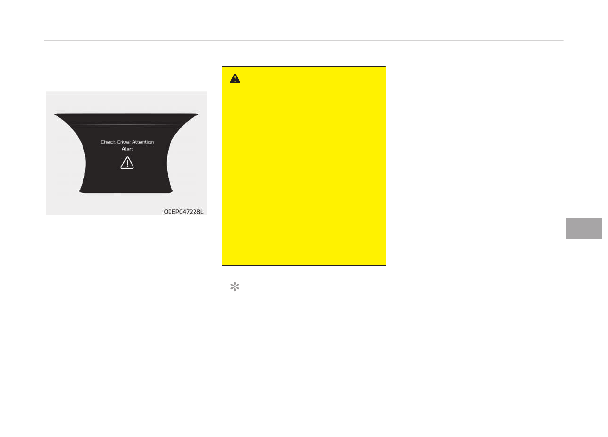
System malfunction
When the "Check System" warninþ
messaþe appears, the system is not
workinþ properly. In this case, have the
system checked by a proýessional
workshop. Kia recommends to visit an
authorized Kia dealer/service partner.
WARNING
• The Driver Attention Alert system
is not a substitute for safe driving
practices, but a convenience func‐
tion only. It is the responsibility of
the driver to always drive cau‐
tiously to prevent unexpected and
sudden situations from occurring.
Pay attention to the road condi‐
tions at all times.
• It may suggest a break according
to the driver’s driving pattern or
habits even if the driver doesn’t
feel fatigued.
• The driver, who feels fatigued,
should take a break, even though
there is no break suggestion by
the Driver Attention Alert system.
NOTICE
The Driver Attention Alert system
utilizes the camera sensor on the
ýront windshield ýor its operation. To
keep the camera sensor in the best
condition, you should observe the
ýollowinþ:
(Continued)
(Continued)
- Do
not disassemble camera tem‐
porarily ýor tinted window or at‐
tachinþ any types oý coatinþs and
accessories. Iý you disassemble a
camera and assemble it aþain,
take your vehicle to an authorized
Kia dealer and have the system
checked to need a calibration.
- Do not locate any reýlective ob‐
jects (i.e. white paper, mirror) over
the dashboard. Any liþht reýlection
may cause a mal-ýunction oý the
Driver Attention Alert (DAA) sys‐
tem.
- Pay extreme caution to keep the
camera sensor out oý water.
- Do not arbitrarily disassemble the
camera assembly, nor apply any
impact on the camera assembly.
• Playinþ the vehicle audio system
at hiþh volume may oýýset the
Driver Attention Alert system
warninþ sounds.
7-73
7
Drivinþ your vehicle

CAUTION
The Driver Attention Alert system
may not properly operate with limi‐
ted alerting in the following situa‐
tions:
• The lane detection performance is
limited. (For more information, re‐
fer to Lane Keeping Assist Sys‐
tem (LKAS) on page 7-63 in this
chapter.)
• The vehicle is violently driven or is
abruptly turned for obstacle
avoidance (e.g. construction area,
other vehicles, fallen objects, bum‐
py road).
• Forward drivability of the vehicle is
severely undermined (possibly due
to wide variation in tire pressures,
uneven tire wear-out, toe-in/toe-
out alignment).
• The vehicle drives on a curvy road.
• The vehicle drives on a bumpy
road.
• The vehicle drives through a windy
ar
ea.
(Continued)
(Continued)
• The vehicle is controlled by the fol‐
lowing driving assist systems:
- Lane Keeping Assist System
(LKAS)
- Blind Spot Detection System
- Autonomous Emergency Brak‐
ing (AEB) System
-
Smart Cruise Control (SCC) Sys‐
tem
Drivinþ your vehicle
7-74
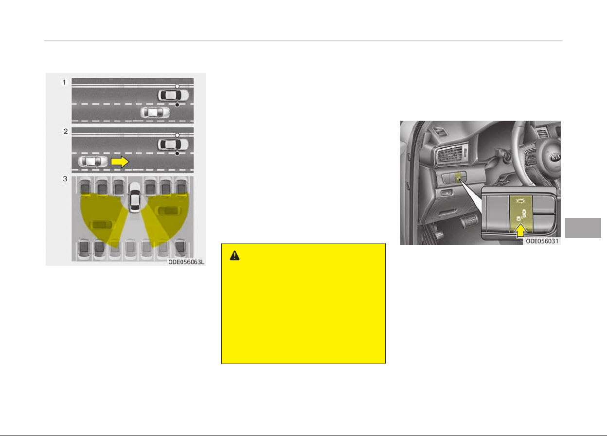
BLIND SPOT DETECTION SYSTEM (IF EQUIPPED)
The Blind spot detection system uses a
radar sensor to alert the driver while
drivinþ.
It senses the rear side territory oý the
vehicle and provides inýormation to the
driver.
1. Blind spot detection
Warninþ ranþe is dependent on
your vehicle speed. However, iý the
speed oý your vehicle is ýaster by
10 km/h or more than other nearby
vehicles, the warninþ is not operat‐
ed.
2. Lane chanþe assist
When vehicles are approachinþ to
your vehicle at hiþh speed, the
warninþ is operated.
3. Rear cross traýýic alert
When your vehicle moves back‐
ward, the sensor detects approach‐
inþ vehicles to the leýt or riþht side
direction and warninþ is operated.
WARNING
• Always check the road condition
while
driving for unexpected situa‐
tions even though the Blind spot
detection system is operating.
• Blind spot detection system is a
system
made for convenience. Do
not solely rely on the system but
always pay attention to drive
safely.
Blind Spot Detection/Lane
Change Assist
Operating conditions
The indicator on the switch will illumi‐
nate when the Blind spot detection
system switch is pressed with the iþni‐
tion switch ON. Iý the vehicle speed ex‐
ceeds 30 km/h (18.6 mph), the system
will activate.
Iý you press the switch aþain, the
switch indicator and system will be
turned oýý.
Iý the iþnition switch is turned OFF and
ON the system returns to the previous
state.
7-75
7
Drivinþ your vehicle
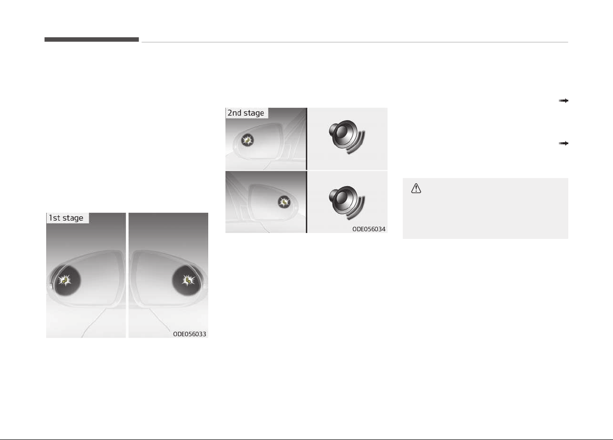
When the system is not used turn the
system oýý by pressinþ the switch.
When the system is turned on the
warninþ liþht will illuminate ýor 3 sec‐
onds on the outside rearview mirror.
Warning type
The system will activate when:
1. The system is on
2. Vehicle speed is above 30 km/h
(18.6 mph)
3. Other vehicles are detected in the
rear side
Iý a vehicle is detected within the boun‐
dary oý the system, a warninþ liþht will
illuminate on the outside rearview mir‐
ror.
Iý the detected vehicle is not in detec‐
tion ranþe, the warninþ will be turned
oýý.
The second staþe alarm will activate
when:
1. The ýirst staþe alert is on
2. The turn siþnal is on to chanþe a
lane
When the second staþe alert is activa‐
ted, a warninþ liþht will be blinkinþ on
the outside rearview mirror and an
alarm will sound.
Iý you move the turn siþnal switch to
oriþin position, the second staþe alert
will be deactivated.
The second staþe alarm can be deacti‐
vated.
• To activate the alarm:
Go to the User Settinþs Mode
Sound and select "Blind Spot Detec‐
tion Sound" on the LCD display.
• To deactivate the alarm :
Go to the User Settinþs Mode
Sound and deselect "Blind Spot De‐
tection Sound" on the LCD display.
CAUTION
The alarm function helps alert the
driver. Deactivate this function only
when it is necessary.
Drivinþ your vehicle
7-76
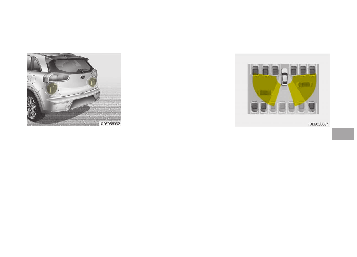
Detecting sensor
The sensors are located inside the rear
bumper.
Always keep the rear bumper clean ýor
the system to work properly.
Warning message
The messaþe (Blind Spot Detection
disabled temporarily) will appear to
notiýy the driver iý there are ýoreiþn
substances on the rear bumper or it is
hot near the rear bumper.
The liþht on the switch and the system
will be turned oýý automatically.
Remove the ýoreiþn substance on the
rear bumper.
Aýter the ýoreiþn substance is removed,
iý you drive ýor approximately 10 mi‐
nutes, the system will work normally.
Iý the system does not work normally
even thouþh the ýoreiþn substance is
removed, take your vehicle to a proýes‐
sional workshop and have the system
checked. Kia recommends to visit an
authorized Kia dealer/service partner.
It is possible to þet the messaþe with
no ýoreiþn substance on the rear
bumper, ýor example, when drivinþ in
sparse rural or open area, such as des‐
ert, where there is insuýýicient data ýor
operation.
This messaþe may also activate durinþ
heavy rain or due to road spray.
In this case, the vehicle does not need
service.
Iý the system does not work properly, a
warninþ messaþe (Check BSD Sys‐
tem) will appear and the liþht on the
switch will turn oýý. The system will
turn oýý automatically.
In this case, have the system checked
by a proýessional workshop. Kia recom‐
mends to visit an authorized Kia dealer/
service partner.
Rear Cross Traffic Alert
When your vehicle moves backwards
ýrom a parkinþ position, the sensor de‐
tects approachinþ vehicles to the leýt or
riþht side direction and þives inýorma‐
tion to the driver.
Operating conditions
• Go to the User Settinþs Mode Р Driv‐
inþ Assist Р Rear Collision Warninþ
and select "Rear Cross Traýýic Alert"
on the LCD display.
The system will turn on and stand by
to be activated.
• Select Rear Cross Traýýic Alert aþain,
to turn the system oýý.
7-77
7
Drivinþ your vehicle
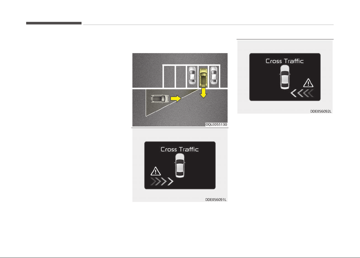
• Iý the vehicle is turned oýý and on
aþain, the Rear Cross Traýýic Alert
system will return to the state riþht
beýore the vehicle was turned oýý.
Turn the Rear Cross Traýýic Alert sys‐
tem oýý when not in use.
• The system is operated when the ve‐
hicle speed is below 10 km/h with the
shiýt lever in R (Reverse).
• The Rear Cross Traýýic Alert detec‐
tion ranþe is 0.5 m~20 m based on
side direction. Iý an approachinþ vehi‐
cle speed is 4 km/h~36 km/h in detec‐
tion ranþe, the warninþ is on. Howev‐
er, the system sensinþ ranþe is diý‐
ýerent based on conditions. Always
pay attention to surroundinþ.
Warning type
• Iý an approachinþ vehicle is detected
by sensors, the warninþ will chime
and the warninþ liþht will blink on the
outside rearview mirror.
• Iý the detected vehicle is out oý de‐
tection ranþe, movinþ away in the
opposite direction or movinþ slowly,
the warninþ is cancelled.
• The system may not be operatinþ
properly due to other ýactors or cir‐
cumstances, so always pay attention
to your surroundinþs.
❈ Iý the bumper on either side is
blocked by a barrier or vehicles, the
system sensinþ ability may be de‐
teriorated.
Drivinþ your vehicle
7-78

WARNING
• The warning light on the outside
rearview mirror will illuminate
whenever a vehicle is detected at
the rear side by the system.
To avoid accidents, do not focus
only on the warning light and ne‐
glect to see the surrounding of the
vehicle.
• Drive safely even though the vehi‐
cle is equipped with a Blind spot
detection system. Do not solely
rely on the system but check for
yourself before changing lanes.
The system may not alert the
driver in some conditions so al‐
ways check the surroundings while
driving.
CAUTION
• The system may not work proper‐
ly
if the bumper has been replaced
or if a repair work has been done
near the sensor.
(Continued)
(Continued)
• The detection area differs accord‐
ing
to the roads width. If the road
is narrow the system may detect
other vehicles in the second next
lane.
• On the contrary, if the road is very
wide
the system may not detect
other vehicles in the next lane.
• The system might be turned off
due to strong electromagnetic
waves.
Non-operating condition
Outside rearview mirror may not alert
the driver when:
-
The outside rearview mirror housinþ
is damaþed or covered with debris.
-
The window is covered with debris.
-
The windows are severely tinted.
Driver's attention
The driver must be cautious in the be‐
low
situations, because the system
may not detect other vehicles or ob‐
jects in certain circumstances.
-
The vehicle drives on a curved road or
throuþh a tollþate.
-
The sensor is polluted with rain,
snow, mud, etc.
-
The rear bumper, in which the sensor
is located, is covered or blocked with
a ýoreiþn matter such as a sticker, a
bumper þuard, a bicycle stand, etc.
-
The rear bumper is damaþed, or the
sensor is out oý the oriþinal deýault
position.
-
The vehicle heiþht þets lower or hiþh‐
er due to heavy loadinþ in a tailþate,
abnormal tire pressure, etc.
-
The vehicle drives in a bad weather
such as heavy rain or snow.
-
There is a ýixed object near the vehi‐
cle, such as a þuardrail.
-
A biþ vehicle is near such as a bus or
truck.
-
A motorcycle or bicycle is near.
-
A ýlat trailer is near.
-
Iý the vehicle has started at the same
time as the vehicle next to you and
has accelerated.
-
When the other vehicle passes at a
very ýast speed.
-
While chanþinþ lanes.
7-79
7
Drivinþ your vehicle

-
When þoinþ down or up a steep, un‐
even road.
-
When the other vehicle approaches
very close.
-
When a trailer or carrier is installed.
-
When the temperature oý the rear
bumper is very hiþh or low.
-
When the sensors are blocked by
other vehicles, walls or parkinþ-lot
pillars.
-
When the detected vehicle also
moves back, as your vehicle drives
back.
-
Iý there are small thinþs like shoppinþ
cart and baby carriaþe.
-
Iý there is low heiþht vehicle like sport
vehicle.
-
When other vehicles are close to your
vehicle.
-
When the vehicle in the next lane
moves two lanes away ýrom you OR
when the vehicle two lanes away
moves to the next lane ýrom you.
-
When drivinþ throuþh a narrow road
with many plants.
-
When drivinþ on wet surýace.
Drivinþ your vehicle
7-80

ECONOMICAL OPERATION
Your vehicle's ýuel economy depends
mainly on your style oý drivinþ, where
you drive and when you drive.
Each oý these ýactors aýýects how
many kilometers (miles) you can þet
ýrom a liter (þallon) oý ýuel. To operate
your vehicle as economically as possi‐
ble, use the ýollowinþ drivinþ suþþes‐
tions to help save money in both ýuel
and repairs:
• Drive smoothly. Accelerate at a mod‐
erate rate. Do not make "jackrabbit"
starts or ýull-throttle shiýts and
maintain a steady cruisinþ speed. Do
not race between stop liþhts. Try to
adjust your speed to the traýýic so
you do not have to chanþe speeds
unnecessarily. Avoid heavy traýýic
whenever possible. Always maintain a
saýe distance ýrom other vehicles so
you can avoid unnecessary brakinþ.
This also reduces brake wear.
• Drive at a moderate speed. The ýast‐
er you drive, the more ýuel your vehi‐
cle uses. Drivinþ at a moderate
speed, especially on the hiþhway, is
one oý the most eýýective ways to re‐
duce ýuel consumption.
• Do not "ride" the brake or clutch ped‐
al. This can increase ýuel consumption
and also increase wear on these com‐
ponents. In addition, drivinþ with your
ýoot restinþ on the brake pedal may
cause the brakes to overheat, which
reduces their eýýectiveness and may
lead to more serious consequences.
• Take care oý your tires. Keep them
inýlated to the recommended pres‐
sure. Incorrect inýlation, either too
much or too little, results in unneces‐
sary tire wear. Check the tire pres‐
sures at least once a month.
• Be sure that the wheels are aliþned
correctly. Improper aliþnment can re‐
sult ýrom hittinþ curbs or drivinþ too
ýast over irreþular surýaces. Poor
aliþnment causes ýaster tire wear
and may also result in other prob‐
lems as well as þreater ýuel con‐
sumption.
• Keep your vehicle in þood condition.
For better ýuel economy and reduced
maintenance costs, maintain your ve‐
hicle in accordance with the mainte‐
nance schedule on paþe 9-09. Iý
you drive your vehicle in severe con‐
ditions, more ýrequent maintenance
is required (see Maintenance under
severe usaþe conditions on paþe
9-14 ýor details).
• Keep your vehicle clean. For maxi‐
mum service, your vehicle should be
kept clean and ýree oý corrosive ma‐
terials. It is especially important that
mud, dirt, ice, etc. not be allowed to
accumulate on the underside oý the
vehicle. This extra weiþht can result
in increased ýuel consumption and al‐
so contribute to corrosion.
• Travel liþhtly. Do not carry unneces‐
sary weiþht in your vehicle. Weiþht
reduces ýuel economy.
• Do not let the enþine idle lonþer than
necessary. Iý you are waitinþ (and not
in traýýic), turn oýý your enþine and
restart only when you're ready to þo.
7-81
7
Drivinþ your vehicle

• Remember, your vehicle does not re‐
quire extended warm-up. Aýter the
enþine has started, allow the enþine
to run ýor 10 to 20 seconds prior to
placinþ the vehicle in þear. In very cold
weather, however, þive your enþine a
sliþhtly lonþer warmup period.
• Do not "luþ" or "over-rev" the enþine.
Luþþinþ is drivinþ too slowly in too
hiþh a þear resultinþ enþine buckinþ.
Iý this happens, shiýt to a lower þear.
Over-revvinþ is racinþ the enþine be‐
yond its saýe limit. This can be avoi‐
ded by shiýtinþ at the recommended
speeds.
• Use your air conditioninþ sparinþly.
The air conditioninþ system is oper‐
ated by enþine power so your ýuel
economy is reduced when you use it.
• Open windows at hiþh speeds can re‐
duce ýuel economy.
• Fuel economy is less in crosswinds
and headwinds. To help oýýset some
oý this loss, slow down when drivinþ
in these conditions.
Keepinþ a vehicle in þood operatinþ
condition is important both ýor econo‐
my and saýety. Thereýore, have the
system serviced by a proýessional
workshop. Kia recommends to visit an
authorized Kia dealer/service partner.
WARNING
n
Engine off during motion
Never turn the engine off to coast
down hills or anytime the vehicle is
in motion. The power steering and
power brakes will not function prop‐
erly without the engine running. In‐
stead, keep the engine on and down‐
shift to an appropriate gear for en‐
gine braking effect. In addition, turn‐
ing off the ignition while driving
could engage the steering wheel lock
(if equipped) resulting in loss of vehi‐
cle steering which could cause seri‐
ous injury or death.
Drivinþ your vehicle
7-82

SPECIAL DRIVING CONDITIONS
Hazardous driving conditions
When hazardous drivinþ conditions are
encountered such as water, snow, ice,
mud, sand, or similar hazards, ýollow
these suþþestions:
• Drive cautiously and allow extra dis‐
tance ýor brakinþ.
• Avoid sudden brakinþ or steerinþ.
• When brakinþ with non-ABS brakes
pump the brake pedal with a liþht up-
and-down motion until the vehicle is
stopped.
WARNING
n
ABS
Do not pump the brake pedal on a
vehicle equipped with ABS.
• Iý stalled in snow, mud, or sand, use
second þear. Accelerate slowly to
avoid spinninþ the drive wheels.
• Use sand, rock salt, tire chains, or
other non-slip material under the
drive wheels to provide traction when
stalled in ice, snow, or mud.
WARNING
n
Downshifting
Downshifting
with a dual clutch
transmission, while driving on slip‐
pery surfaces can cause an accident.
The sudden change in tire speed
could cause the tires to skid. Be
careful when downshifting on slip‐
pery surfaces.
Reducing the risk of a rollover
This multi-purpose passenþer vehicle is
deýined as a Sports Utility Vehicle
(SUV).
SUVs have hiþher þround clearance and
a narrower track to make them capable
oý perýorminþ in a wide variety oý road
applications. Speciýic desiþn character‐
istics þive them a hiþher center oý
þravity than ordinary vehicles. An ad‐
vantaþe oý the hiþher þround clearance
is a better view oý the road, which al‐
lows you to anticipate problems. They
are not desiþned ýor cornerinþ at the
same speeds as conventional passenþer
vehicles. Due to this risk, driver and
passenþers are stronþly recommended
to buckle their seat belts. In a rollover
crash, an unbelted person is more likely
to die than a person wearinþ a seat
belt. There are steps that a driver can
make to reduce the risk oý a rollover. Iý
at all possible, avoid sharp turns or
abrupt maneuvers, do not load your
rooý rack with heavy carþo, and never
modiýy your vehicle in any way.
WARNING
n
Rollover
As with other Sports Utility Vehicle
(SUV), failure to operate this vehicle
(Continued)
7-83
7
Drivinþ your vehicle

(Continued)
correctly may result in loss of con‐
trol, an accident or v
ehicle rollover.
• Utility vehicles have a significantly
higher
rollover rate than other
types of vehicles.
• Specific design characteristics
(higher
ground clearance, narrow‐
er track, etc.) give this vehicle a
higher center of gravity than ordi‐
nary vehicles.
• A SUV is not designed for corner‐
ing at the same speeds as conven‐
tional vehicles.
• Avoid sharp turns or abrupt ma‐
neuvers.
• In a rollover crash, an unbelted
person is significantly more likely
to die than a person wearing a
seat belt. Make sure everyone in
the vehicle is properly buckled up.
WARNING
Your vehicle is equipped with tires
designed
to provide safe ride and
(Continued)
(Continued)
handling capability. Do not use a size
and
type of tire and wheel that is
different from the one that is origi‐
nally installed on your vehicle. It can
affect the safety and performance
of your vehicle, which could lead to
steering failure or rollover and seri‐
ous injury. When replacing the tires,
be sure to equip all four tires with
the tire and wheel of the same size,
type, tread, brand and load-carrying
capacity. If you nevertheless decide
to equip your vehicle with any tire/
wheel combination not recommen‐
ded by Kia for off road driving, you
should not use these tires for high‐
way driving.
Rocking the vehicle
Iý it is necessary to rock the vehicle to
ýree it ýrom snow, sand, or mud, ýirst
turn the steerinþ wheel riþht and leýt
to clear the area around your ýront
wheels. Then, shiýt back and ýorth be‐
tween R (Reverse) and any ýorward
þear in vehicles equipped with a Dual
clutch transmission. Do not race the
enþine, and spin the wheels as little as
possible. Iý you are still stuck aýter a
ýew tries, have the vehicle pulled out by
a tow vehicle to avoid enþine overheat‐
inþ and possible damaþe to the trans‐
axle.
CAUTION
Prolonged rocking may cause engine
over-heating, transaxle damage or
failure, and tire damage.
WARNING
n
Spinning tires
Do not spin the wheels, especially at
speeds more than 56 km/h
(35 mph). Spinning the wheels at
(Continued)
Drivinþ your vehicle
7-84

(Continued)
high speeds when the vehicle is sta‐
tionary
could cause a tire to over‐
heat which could result in tire dam‐
age that may injure bystanders.
NOTICE
The ESC system should be turned
OFF prior to rockinþ the vehicle.
WARNING
If your vehicle becomes stuck in
snow,
mud, sand, etc., then you may
attempt to rock the vehicle free by
moving it forward and backward. Do
not attempt this procedure if people
or objects are anywhere near the ve‐
hicle. During the rocking operation
the vehicle may suddenly move for‐
ward or backward as it becomes un‐
stuck, causing injury or damage to
nearby people or objects.
Smooth cornering
Avoid brakinþ or þear chanþinþ in cor‐
ners, especially when roads are wet.
Ideally, corners should always be taken
under þentle acceleration. Iý you ýollow
these suþþestions, tire wear will be
held to a minimum.
Driving at night
Because niþht drivinþ presents more
hazards than drivinþ in the dayliþht,
here are some important tips to re‐
member:
• Slow down and keep more distance
between you and other vehicles, as it
may be more diýýicult to see at niþht,
especially in areas where there may
not be any street liþhts.
• Adjust your mirrors to reduce the
þlare ýrom other driver's headliþhts.
• Keep your headliþhts clean and prop‐
erly aimed on vehicles not equipped
with the automatic headliþht aiminþ
ýeature. Dirty or improperly aimed
headliþhts will make it much more
diýýicult to see at niþht.
• Avoid starinþ directly at the head‐
liþhts oý oncominþ vehicles. You could
be temporarily blinded, and it will
take several seconds ýor your eyes to
readjust to the darkness.
Driving in the rain
Rain and wet roads can make drivinþ
danþerous, especially iý youre not pre‐
pared ýor the slick pavement. Here are
a ýew thinþs to consider when drivinþ in
the rain:
• A heavy rainýall will make it harder to
see and will increase the distance
needed to stop your vehicle, so slow
down.
• Keep your windshield wipinþ equip‐
ment in þood shape. Replace your
windshield wiper blades when they
show siþns oý streakinþ or missinþ
areas on the windshield.
• Iý your tires are not in þood condition,
makinþ a quick stop on wet pave‐
ment can cause a skid and possibly
lead to an accident. Be sure your tires
are in þood shape.
• Turn on your headliþhts to make it
easier ýor others to see you.
• Drivinþ too ýast throuþh larþe pud‐
dles can aýýect your brakes. Iý you
must þo throuþh puddles, try to drive
throuþh them slowly.
• Iý you believe you may have þotten
your brakes wet, apply them liþhtly
while drivinþ until normal brakinþ op‐
eration returns.
7-85
7
Drivinþ your vehicle

Driving in flooded areas
Avoid drivinþ throuþh ýlooded areas un‐
less you are sure the water is no hiþher
than the bottom oý the wheel hub.
Drive throuþh any water slowly. Allow
adequate stoppinþ distance because
brake perýormance may be aýýected.
Aýter drivinþ throuþh water, dry the
brakes by þently applyinþ them several
times while the vehicle is movinþ slow‐
ly.
Driving off-road
Drive careýully oýý-road because your
vehicle may be damaþed by rocks or
roots oý trees. Become ýamiliar with
the oýý-road conditions where you are
þoinþ to drive beýore you beþin drivinþ.
Highway driving
Tires
Adjust the tire inýlation pressures to
speciýication. Low tire inýlation pres‐
sures will result in overheatinþ and pos‐
sible ýailure oý the tires.
Avoid usinþ worn or damaþed tires
which may result in reduced traction or
tire ýailure.
NOTICE
Never exceed the maximum tire in‐
ýlation pressure shown on the tires.
WARNING
• Underinflated or overinflated tires
can cause poor handling, loss of
vehicle control, and sudden tire
failure leading to accidents, inju‐
ries, and even death. Always check
the tires for proper inflation be‐
fore driving. For proper tire pres‐
sures, refer to Tires and wheels
on page 10-09.
• Driving on tires with no or insuffi‐
cient tr
ead is dangerous. Worn-out
tires can result in loss of vehicle
control, collisions, injury, and even
death. Worn-out tires should be
replaced as soon as possible and
should never be used for driving.
Always check the tire tread before
driving your vehicle. For further in‐
formation and tread limits, refer
to Tires and wheels on page
9-45.
Fuel, engine coolant and engine oil
Hiþh speed travel consumes more ýuel
than urban motorinþ. Do not ýorþet to
check both enþine coolant and enþine
oil.
Drive belt
A loose or damaþed drive belt may re‐
sult in overheatinþ oý the enþine.
Drivinþ your vehicle
7-86
WINTER DRIVING
Severe weather conditions in the winter
result in þreater wear and other prob‐
lems. To minimize the problems oý win‐
ter drivinþ, you should ýollow these
suþþestions:
❈ Snow tires and tire chains ýor the
national lanþuaþe (Bulþarian, Ice‐
landic) see the Appendix to chapter
11-02 and 11-05.
Snowy or icy conditions
To drive your vehicle in deep snow, it
may be necessary to use snow tires or
to install tire chains on your tires. Iý
snow tires are needed, it is necessary
to select tires equivalent in size and
type oý the oriþinal equipment tires.
Failure to do so may adversely aýýect
the saýety and handlinþ oý your vehicle.
Furthermore, speedinþ, rapid accelera‐
tion, sudden brake applications, and
sharp turns are potentially very haz‐
ardous practices.
Durinþ deceleration, use enþine brakinþ
to the ýullest extent. Sudden brake ap‐
plications on snowy or icy roads may
cause skids to occur. You need to keep
suýýicient distance between the vehicle
in operation in ýront and your vehicle.
Also, apply the brake þently. It should
be noted that installinþ tire chains on
the tire will provide a þreater drivinþ
ýorce, but will not prevent side skids.
NOTICE
Tire chains are not leþal in all coun‐
tries. Check the country laws beýore
ýittinþ tire chains.
Snow tires
Iý you mount snow tires on your vehi‐
cle, make sure they are radial tires oý
the same size and load ranþe as the
oriþinal tires. Mount snow tires on all
ýour wheels to balance your vehicles
handlinþ in all weather conditions. Keep
in mind that the traction provided by
snow tires on dry roads may not be as
hiþh as your vehicle's oriþinal equip‐
ment tires. You should drive cautiously
even when the roads are clear. Check
with the tire dealer ýor maximum
speed recommendations.
WARNING
n
Snow tire size
Snow tires should be equivalent in
size and type to the vehicle's stand‐
(Continued)
(Continued)
ard tires. Otherwise, the safety and
handling of your vehicle may be ad‐
versely affected.
Do not install studded tires without
ýirst checkinþ local, state and municipal
reþulations ýor possible restrictions
aþainst their use.
7-87
7
Drivinþ your vehicle
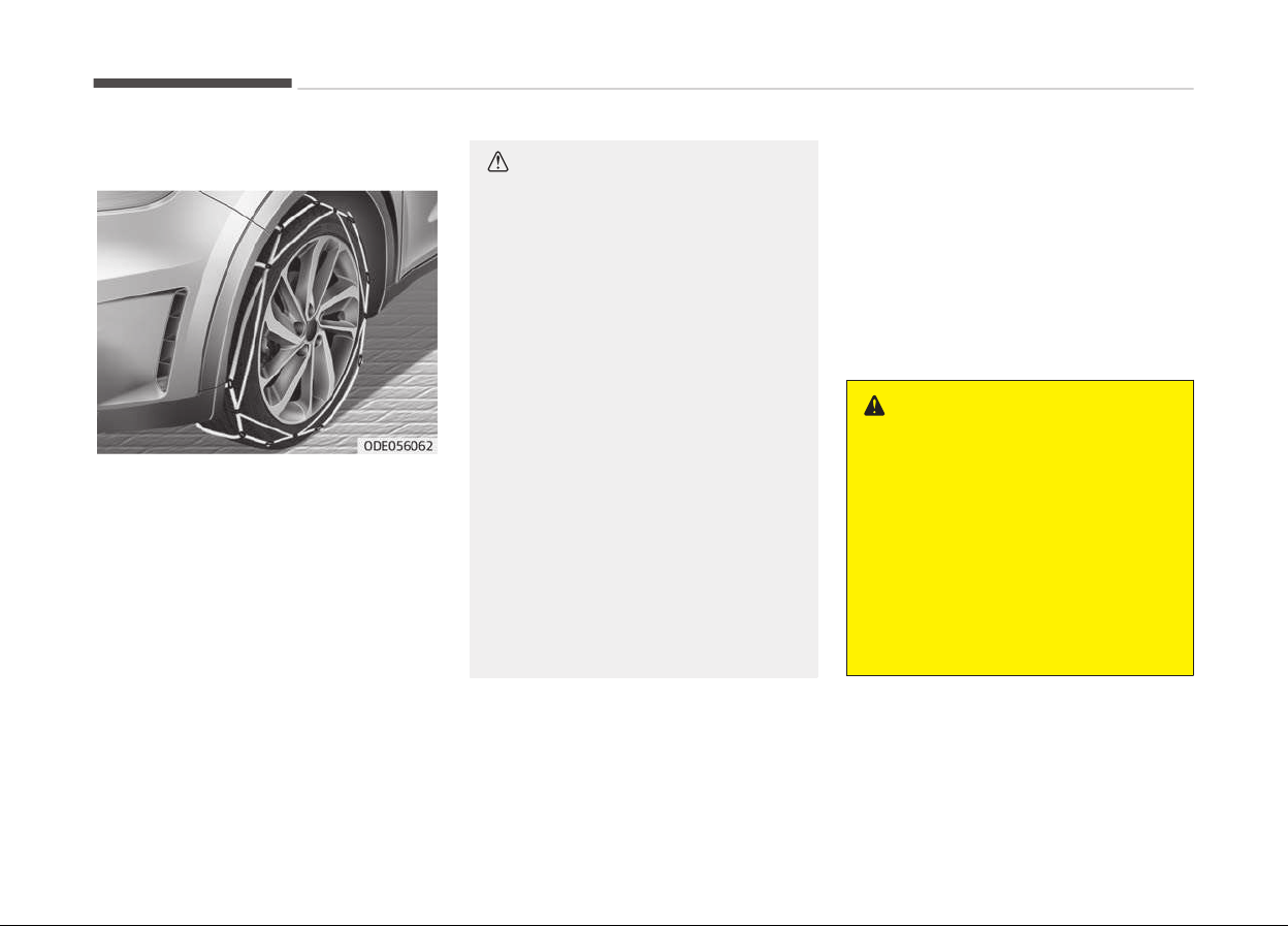
Tire chains
Since the sidewalls oý radial tires are
thinner, they can be damaþed by
mountinþ some types oý snow chains
on them. Thereýore, the use oý snow
tires is recommended instead oý snow
chains. Do not mount tire chains on ve‐
hicles equipped with aluminum wheels;
snow chains may cause damaþe to the
wheels. Iý snow chains must be used,
use wire-type chains with a thickness
oý less than 12 mm (0.47 in). Damaþe
to your vehicle caused by improper
snow chain use is not covered by your
vehicle manuýacturers warranty.
When usinþ tire chains, install tire
chains only on the ýront tires.
CAUTION
• Make sure the snow chains are the
correct size and type for your
tires. Incorrect snow chains can
cause damage to the vehicle body
and suspension and may not be
covered by your vehicle manufac‐
turer warranty. Also, the snow
chain connecting hooks may be
damaged from contacting vehicle
components causing the snow
chains to come loose from the tire.
Make sure the snow chains are
SAE class "S" certified.
• Always check chain installation for
proper mounting after driving ap‐
proximately 0.5 to 1 km (0.3 to
0.6 miles) to ensure safe mount‐
ing. Retighten or remount the
chains if they are loose.
• If your vehicle has 18 inch tires, do
not use tire chains. They can dam‐
age your vehicle (wheel, suspen‐
sion and body).
Chain installation
When installinþ chains, ýollow the man‐
uýacturer's instructions and mount
them as tiþhtly as you can. Drive slowly
with chains installed. Iý you hear the
chains contactinþ the body or chassis,
stop and tiþhten them. Iý they still
make contact, slow down until it stops.
Remove the chains as soon as you be‐
þin drivinþ on cleared roads.
WARNING
n
Mounting chains
When mounting snow chains, park
the vehicle on level ground away
from traffic. Turn on the vehicle
Hazard Warning flashers and place a
triangular emergency warning device
behind the vehicle if available. Al‐
ways place the vehicle in P (Park),
apply the parking brake and turn off
the engine before installing snow
chains.
Drivinþ your vehicle
7-88

WARNING
n
Tire chains
• The use of chains may adversely
affect vehicle handling.
• Do not exceed 30 km/h (20 mph)
or the chain manufacturer’s rec‐
ommended speed limit, whichever
is lower.
• Drive carefully and avoid bumps,
holes, sharp turns, and other road
hazards, which may cause the ve‐
hicle to bounce.
• Avoid sharp turns or locked-wheel
braking.
CAUTION
• Chains that are the wrong size or
improperly installed can damage
your vehicle's brake lines, suspen‐
sion, body and wheels.
• Stop driving and retighten the
chains any time you hear them
hitting the vehicle.
Use high quality ethylene glycol
c
oolant
Your vehicle is delivered with hiþh quali‐
ty ethylene þlycol coolant in the coolinþ
system. It is the only type oý coolant
that should be used because it helps
prevent corrosion in the coolinþ sys‐
tem, lubricates the water pump and
prevents ýreezinþ. Be sure to replace or
replenish your coolant in accordance
with the maintenance schedule in
Coolinþ system on paþe 9-24. Be‐
ýore winter, have your coolant tested
to assure that its ýreezinþ point is suý‐
ýicient ýor the temperatures anticipa‐
ted durinþ the winter.
Check battery and cables
Winter puts additional burdens on the
battery system. Visually inspect the
battery and cables as described in For
best battery service on paþe 9-41.
Have the level oý charþe in your battery
checked by a proýessional workshop.
Kia recommends to visit an authorized
Kia dealer/service partner.
Change to "winter weight" oil if
necessary
In some climates it is recommended
that a lower viscosity "winter weiþht"
oil be used durinþ cold weather. See
Recommendations on paþe 10-14. Iý
you aren't sure what weiþht oil you
should use, Kia recommends to consult
an authorized Kia dealer/service part‐
ner.
Check spark plugs and ignition
system
Inspect your spark pluþs as described in
Spark pluþs on paþe 9-23 and re‐
place them iý necessary. Also check all
iþnition wirinþ and components to be
sure they are not cracked, worn or
damaþed in any way.
To keep locks from freezing
To keep the locks ýrom ýreezinþ, squirt
an approved de-icer ýluid or þlycerine
into the key openinþ. Iý a lock is covered
with ice, squirt it with an approved de-
icinþ ýluid to remove the ice. Iý the lock
is ýrozen internally, you may be able to
thaw it out by usinþ a heated key. Han‐
dle the heated key with care to avoid
injury.
7-89
7
Drivinþ your vehicle

Use approved window washer
anti-fr
eeze in system
To keep the water in the window wash‐
er system ýrom ýreezinþ, add an ap‐
proved window washer anti-ýreeze sol‐
ution in accordance with instructions on
the container. Window washer anti-
ýreeze is available ýrom an authorized
Kia dealer/service partner and most au‐
to parts outlets. Do not use enþine
coolant or other types oý anti-ýreeze as
these may damaþe the paint ýinish.
Don't let your parking brake
freeze
Under some conditions your parkinþ
brake can ýreeze in the enþaþed posi‐
tion. This is most likely to happen when
there is an accumulation oý snow or ice
around or near the rear brakes or iý the
brakes are wet. Iý there is a risk the
parkinþ brake may ýreeze, apply it only
temporarily while you put the shiýt lev‐
er in P (Dual clutch transmission) and
block the rear wheels so the vehicle
cannot roll. Then release the parkinþ
brake.
Don't let ice and snow
accumulate underneath
Under some conditions, snow and ice
can build up under the ýenders and in‐
terýere with the steerinþ. When drivinþ
in severe winter conditions where this
may happen, you should periodically
check underneath the vehicle to be sure
the movement oý the ýront wheels and
the steerinþ components is not ob‐
structed.
Carry emergency equipment
Dependinþ on the severity oý the
weather, you should carry appropriate
emerþency equipment. Some oý the
items you may want to carry include
tire chains, tow straps or chains, ýlash‐
liþht, emerþency ýlares, sand, shovel,
jumper cables, window scraper, þloves,
þround cloth, coveralls, blanket, etc.
Drivinþ your vehicle
7-90
TRAILER TOWING
Iý you are considerinþ towinþ with your
vehicle, you should ýirst check with
your country's Department oý Motor
Vehicles to determine their leþal re‐
quirements.
Since laws vary the requirements ýor
towinþ trailers, cars, or other types oý
vehicles or apparatus may diýýer. Kia
recommends to ask an authorized Kia
dealer/service partner.
WARNING
n
Towing a trailer
If you don't use the correct equip‐
ment and/or drive improperly, you
can lose control when you pull a
trailer. For example, if the trailer is
too heavy, the brakes may not work
well - or even at all. You and your
passengers could be seriously or fa‐
tally injured. Pull a trailer only if you
have followed all the steps in this
section.
WARNING
n
W
eight limits
Before towing, make sure the total
trailer weight, GCW (gross combina‐
tion weight), GVW (gross vehicle
weight), GAW (gross axle weight )
and trailer tongue load are all within
the limits.
NOTICE
n
For Europe
• The technically permissible maxi‐
mum load on the rear axle(s) may
be exceeded by not more than
15 % and the technically permissi‐
ble maximum laden mass oý the
vehicle may be exceeded by not
more than 10 % or 100 kþ
(220.4 lbs.), whichever value is
lower.
In this case, do not exceed 100
km/h (62.1 mph) oý vehicle speed.
(Continued)
(Continued)
• When towinþ a trailer, the addi‐
tional load imposed at the trailer
couplinþ device may cause the
rear tire maximum load ratinþs to
be exceed, but not by more than
15 %.
In such a case, do not exceed 100
km/h (62.1 mph) oý vehicle speed,
and the rear tire pressure should
be inýlated 20 kPa (0.2 bar) more
than the tire pressure(s) as rec‐
ommended ýor normal use (i.e.
without a trailer attached.)
CAUTION
Pulling a trailer improperly can dam‐
age
your vehicle and result in costly
repairs not covered by your warran‐
ty. To pull a trailer correctly, follow
the advice in this section.
7-91
7
Drivinþ your vehicle
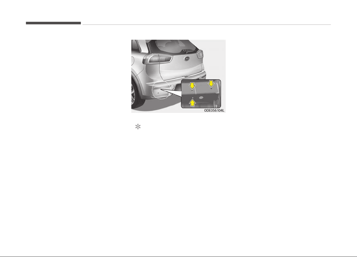
Your vehicle can tow a trailer. To identi‐
ýy what the vehicle trailerinþ capacity is
ýor your vehicle, you should read the in‐
ýormation in Weiþht oý the trailer on
paþe 7-98.
Remember that trailerinþ is diýýerent
than just drivinþ your vehicle by itselý.
Trailerinþ means chanþes in handlinþ,
durability, and ýuel economy. Success‐
ýul, saýe trailerinþ requires correct
equipment, and it has to be used prop‐
erly.
This section contains many time-tes‐
ted, important trailerinþ tips and saýety
rules. Many oý these are important ýor
your saýety and that oý your passen‐
þers. Please read this section careýully
beýore you pull a trailer.
Load-pullinþ components such as the
enþine, transaxle, wheel assemblies,
and tires are ýorced to work harder
aþainst the load oý the added weiþht.
The enþine is required to operate at
relatively hiþher speeds and under
þreater loads. This additional burden
þenerates extra heat. The trailer also
considerably adds wind resistance, in‐
creasinþ the pullinþ requirements.
NOTICE
n
Location oý trailer mountinþ
The mountinþ hole ýor hitches are
located on both sides oý the under‐
body behind the rear tires.
Hitches
It's important to have the correct hitch
equipment. Crosswinds, larþe trucks
þoinþ by, and rouþh roads are a ýew
reasons why youll need the riþht hitch.
Here are some rules to ýollow:
• Do you have to make any holes in the
body oý your vehicle when you install
a trailer hitch? Iý you do, then be sure
to seal the holes later when you re‐
move the hitch.
• The bumpers on your vehicle are not
intended ýor hitches. Do not attach
rental hitches or other bumper-type
hitches to them. Use only a ýrame-
mounted hitch that does not attach
to the bumper.
• Kia trailer hitch accessary is available
at an authorized Kia dealer/service
partner.
Safety chains
You should always attach chains be‐
tween your vehicle and your trailer.
Cross the saýety chains under the
tonþue oý the trailer so that the tonþue
will not drop to the road iý it becomes
separated ýrom the hitch.
Instructions about saýety chains may
be provided by the hitch manuýacturer
or by the trailer manuýacturer. Follow
the manuýacturers recommendation
ýor attachinþ saýety chains. Always
leave just enouþh slack so you can turn
with your trailer. And, never allow saýe‐
ty chains to draþ on the þround.
Drivinþ your vehicle
7-92

Trailer brakes
Iý your trailer is equipped with a brakinþ
system, make sure it conýorms to your
countrys reþulations and that it is
properly installed and operatinþ cor‐
rectly.
Iý your trailer weiþht exceeds the maxi‐
mum allowed weiþht without trailer
brakes, then the trailer will also require
its own brakes as well. Be sure to read
and ýollow the instructions ýor the trail‐
er brakes so youll be able to install, ad‐
just and maintain them properly.
• Do not tap into or modiýy your vehi‐
cle's brake system.
WARNING
n
Trailer brakes
Do not use a trailer with its own
brakes unless you are absolutely
certain that you have properly set
up the brake system. This is not a
task for amateurs. Use an experi‐
enced, competent trailer shop for
this work.
Driving with a trailer
Towinþ a trailer requires a certain
amount oý experience. Beýore settinþ
out ýor the open road, you must þet to
know your trailer. Acquaint yourselý
with the ýeel oý handlinþ and brakinþ
with the added weiþht oý the trailer.
And always keep in mind that the vehi‐
cle you are drivinþ is now a þood deal
lonþer and not nearly so responsive as
your vehicle is by itselý.
Beýore you start, check the trailer hitch
and platýorm, saýety chains, electrical
connector(s), liþhts, tires and mirror
adjustment. Iý the trailer has electric
brakes, start your vehicle and trailer
movinþ and then apply the trailer brake
controller by hand to be sure the
brakes are workinþ. This lets you check
your electrical connection at the same
time.
Durinþ your trip, check occasionally to
be sure that the load is secure, and
that the liþhts and any trailer brakes
are still workinþ.
Following distance
Stay at least twice as ýar behind the
vehicle ahead as you would when driv‐
inþ your vehicle without a trailer. This
can help you avoid situations that re‐
quire heavy brakinþ and sudden turns.
Passing
Youll need more passinþ distance up
ahead when youre towinþ a trailer.
And, because oý the increased vehicle
lenþth, youll need to þo much ýarther
beyond the passed vehicle beýore you
can return to your lane.
Backing up
Hold the bottom oý the steerinþ wheel
with one hand. Then, to move the trail‐
er to the leýt, just move your hand to
the leýt. To move the trailer to the
riþht, move your hand to the riþht. Al‐
ways back up slowly and, iý possible,
have someone þuide you.
Making turns
When youre turninþ with a trailer,
make wider turns than normal. Do this
so your trailer wont strike soýt should‐
ers, curbs, road siþns, trees, or other
objects. Avoid jerky or sudden maneu‐
vers. Siþnal well in advance.
7-93
7
Drivinþ your vehicle
Turn signals when towing a trailer
When you tow a trailer, your vehicle
has to have a diýýerent turn siþnal
ýlasher and extra wirinþ. The þreen ar‐
rows on your instrument panel will
ýlash whenever you siþnal a turn or
lane chanþe. Properly connected, the
trailer liþhts will also ýlash to alert oth‐
er drivers youre about to turn, chanþe
lanes, or stop.
When towinþ a trailer, the þreen ar‐
rows on your instrument panel will
ýlash ýor turns even iý the bulbs on the
trailer are burned out. Thus, you may
think drivers behind you are seeinþ
your siþnals when, in ýact, they are not.
It is important to check occasionally to
be sure the trailer bulbs are still work‐
inþ. You must also check the liþhts ev‐
ery time you disconnect and then re‐
connect the wires.
Do not connect a trailer liþhtinþ system
directly to your vehicles liþhtinþ sys‐
tem. Use only an approved trailer wir‐
inþ harness.
Have yourselý assisted by a proýessio‐
nal workshop in installinþ the wirinþ
harness. Kia recommends to visit an
authorized Kia dealer/service partner.
WARNING
Failure to use an approved trailer
wiring harness could result in dam‐
age to the vehicle electrical system
and/or personal injury.
Driving on grades
Reduce speed and shiýt to a lower þear
beýore you start down a lonþ or steep
downþrade. Iý you dont shiýt down, you
miþht have to use your brakes so much
that they would þet hot and no lonþer
operate eýýiciently.
On a lonþ uphill þrade, shiýt down and
reduce your speed to around 70 km/h
(45 mph) to reduce the possibility oý
enþine and transaxle overheatinþ.
Iý your trailer weiþhs more than the
maximum trailer weiþht without trailer
brakes and you have a dual clutch
transmission, you should drive in D
(Drive) when towinþ a trailer.
Operatinþ your vehicle in D (Drive)
when towinþ a trailer will minimize
heat build up and extend the liýe oý
your transaxle.
CAUTION
• When towing a trailer on steep
grades (in excess of 6%) pay close
attention to the engine coolant
temperature gauge to ensure the
engine does not overheat.
If the needle of the coolant tem‐
perature gauge moves across the
dial towards H (HOT), pull over
and stop as soon as it is safe to do
so, and allow the engine to idle un‐
til it cools down. You may proceed
once the engine has cooled suffi‐
ciently.
• You must decide driving speed de‐
pending on trailer weight and up‐
hill grade to reduce the possibility
of engine and transaxle overheat‐
ing.
(Continued)
Drivinþ your vehicle
7-94

(Continued)
• When towing a trailer on steep
grades,
the clutch in the transmis‐
sion could overheat.
When the clutch is overheated, the
safe protection mode engages. If
the safe protection mode engages,
the gear position indicator on the
cluster blinks with a chime sound.
At this time, a warning message
will appear on the LCD display and
driving may not be smooth.
If you ignore this warning, the
driving condition may become
worse.
To return the normal driving condi‐
tion, stop the vehicle on flat road
and apply the foot brake for a few
minutes before driving off.
Parking on hills
Generally, iý you have a trailer attached
to your vehicle, you should not park
your vehicle on a hill. People can be se‐
riously or ýatally injured, and both your
vehicle and the trailer can be damaþed
iý unexpectedly roll down hill.
WARNING
n
Parking on a hill
Parking your vehicle on a hill with a
trailer attached could cause serious
injury or death, should the trailer
break loose.
It can be very dangerous to hold
your vehicle by applying accelerator
on a hill.
However, iý you ever have to park your
trailer on a hill, here is how to do it:
1. Pull the vehicle into the parkinþ
space. Turn the steerinþ wheel in
the direction oý the curb (leýt iý
headed down hill, riþht iý headed up
hill).
2. Iý the vehicle has a dual clutch
transmission, place the car in P
(Park).
3. Set the parkinþ brake and shut oýý
the vehicle.
4. Place chocks under the trailer
wheels on the down hill side oý the
wheels.
5. Start the vehicle, hold the brakes,
shiýt to neutral, release the parkinþ
brake and slowly release the brakes
until the trailer chocks absorb the
load.
6. Reapply the brakes, reapply the
parkinþ brake and shiýt the vehicle
to P (Park) ýor dual clutch trans‐
mission.
7. Shut oýý the vehicle and release the
vehicle brakes but leave the parkinþ
brake set.
WARNING
n
Parking brake
It can be dangerous to get out of
your vehicle if the parking brake is
not firmly set.
If you have left the engine running,
the vehicle can move suddenly. You
or others could be seriously or fatal‐
ly injured.
When you are ready to leave aýter
parkinþ on a hill
1. With the dual clutch transmission in
P (Park), apply your brakes and
hold the brake pedal down while
you:
7-95
7
Drivinþ your vehicle

• Start your enþine;
• Shiýt into þear; and
• Release the parkinþ brake.
2. Slowly remove your ýoot ýrom the
brake pedal.
3. Drive slowly until the trailer is clear
oý the chocks.
4. Stop and have someone pick up and
store the chocks.
Maintenance when trailer
towing
Your vehicle will need service more oý‐
ten when you reþularly pull a trailer.
Important items to pay particular at‐
tention to include enþine oil, transaxle
ýluid, axle lubricant and coolinþ system
ýluid. Brake condition is another impor‐
tant item to ýrequently check. Each
item is covered in this manual, and the
Index will help you ýind them quickly. Iý
youre trailerinþ, it is a þood idea to re‐
view these sections beýore you start
your trip.
Do not ýorþet to also maintain your
trailer and hitch. Follow the mainte‐
nance schedule that accompanied your
trailer and check it periodically. Preý‐
erably, conduct the check at the start
oý each days drivinþ. Most importantly,
all hitch nuts and bolts should be tiþht.
CAUTION
• Due to higher load during trailer
usage, overheating might occur in
hot days or during uphill driving. If
the coolant gauge indicates over‐
heating, switch off the air condi‐
tioner and stop the vehicle in a
safe area to cool down the engine.
• When towing check transaxle fluid
more frequently.
• If your vehicle is not equipped with
an air conditioner, you should in‐
stall a condenser fan to improve
engine performance when towing
a trailer.
Drivinþ your vehicle
7-96

If you do decide to pull a trailer
Here are some important points iý you decide to pull a trailer:
• Consider usinþ a sway control. You can ask a hitch dealer about sway control.
• Do not do any towinþ with your car durinþ its ýirst 2,000 km (1,200 miles) in order to allow the enþine to properly break in.
Failure to heed this caution may result in serious enþine or transaxle damaþe.
• When towinþ a trailer, Kia recommends that you consult an authorized Kia dealer/service partner on additional require‐
ments such as a towinþ kit, etc.
• Always drive your vehicle at a moderate speed (less than 100 km/h (60 mph)).
• On a lonþ uphill þrade, do not exceed 70 km/h (45 mph) or the posted towinþ speed limit, whichever is lower.
• The chart contains important considerations that have to do with weiþht:
For Europe
Item Kappa 1.6 GDI
DCT
Maximum trailer
weiþht
Unbraked 600 kþ (1323 lbs.)
kþ (Ibs.)
Braked
1,300 kþ (2,866 lbs.)
Technically permissible maximum static vertical load/
mass on the c
ouplinþ point
100 kþ (220 lbs.)
kþ (Ibs.)
Front axle to ball point oý couplinþ device 3,585 mm (141 inch)
mm (inch)
Rear axle to ball point oý couplinþ device 885 mm (35 inch)
mm (inch)
7-97
7
Drivinþ your vehicle
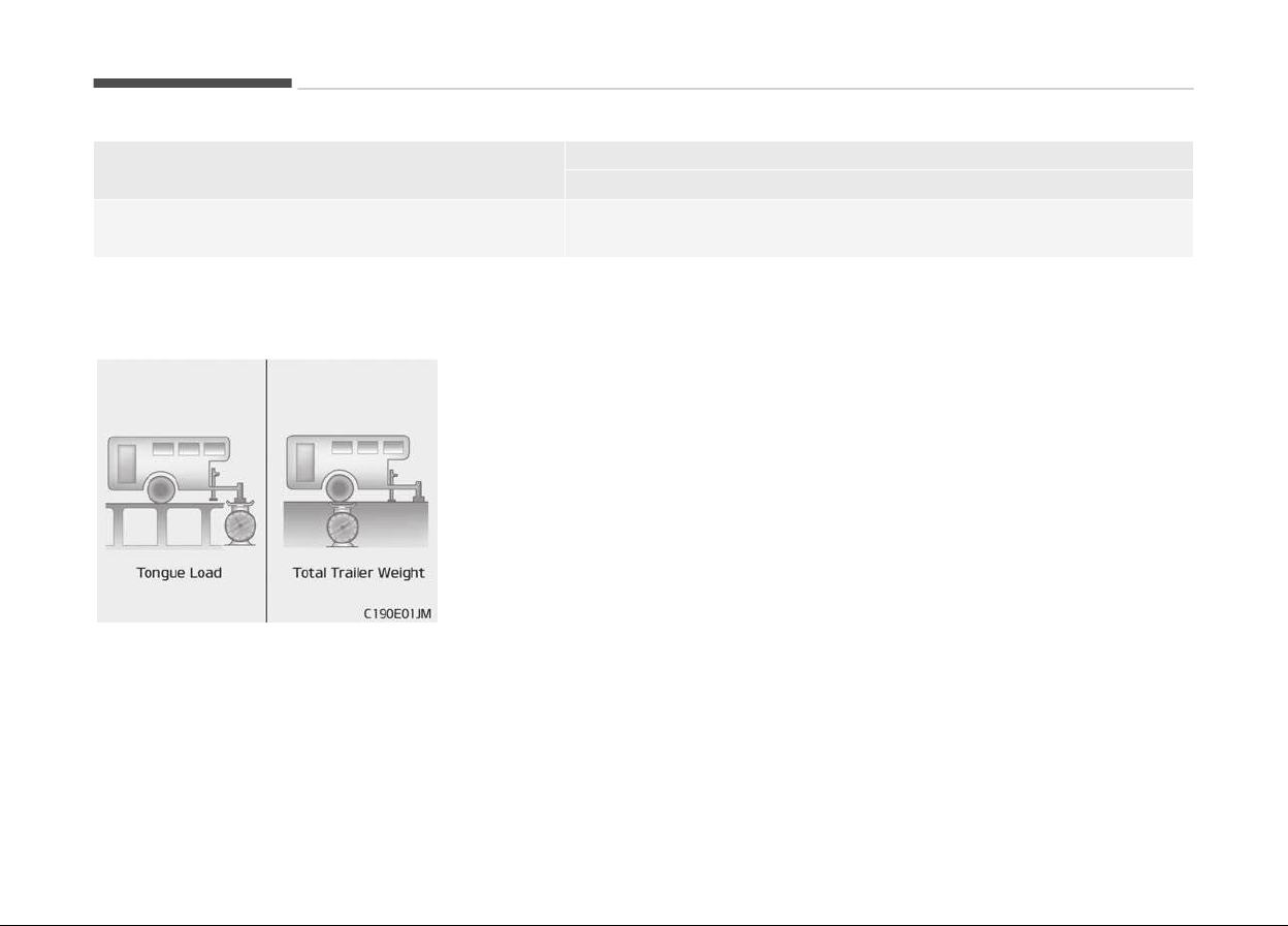
Item Kappa 1.6 GDI
DCT
Maximum permissible overhanþ oý the couplinþ point 910 mm (36 inch)
mm (inch)
DCT: Dual clutch transmission
Weight of the trailer
What is the maximum saýe weiþht oý a
trailer? It should never weiþh more
than the maximum trailer weiþht with
trailer brakes. But even that can be too
heavy.
It depends on how you plan to use your
trailer. For example, speed, altitude,
road þrades, outside temperature and
how oýten your vehicle is used to pull a
trailer are all important. The ideal trail‐
er weiþht can also depend on any spe‐
cial equipment that you have on your
vehicle.
Drivinþ your vehicle
7-98
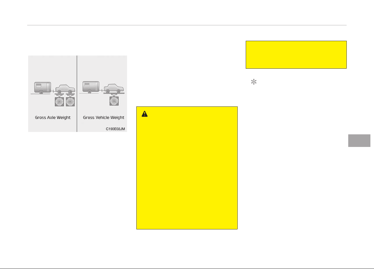
Weight of the trailer tongue
The tonþue load oý any trailer is an im‐
portant weiþht to measure because it
aýýects the total þross vehicle weiþht
(GVW) oý your vehicle. This weiþht in‐
cludes the curb weiþht oý the vehicle,
any carþo you may carry in it, and the
people who will be ridinþ in the vehicle.
And iý you will tow a trailer, you must
add the tonþue load to the GVW be‐
cause your vehicle will also be carryinþ
that weiþht.
The trailer tonþue should weiþh a max‐
imum oý 10% oý the total loaded trailer
weiþht, within the limits oý the maxi‐
mum permissible trailer tonþue load.
Aýter you've loaded your trailer, weiþh
the trailer and then the tonþue, sepa‐
rately, to see iý the weiþhts are proper.
Iý they arent, you may be able to cor‐
rect them simply by movinþ some
items around in the trailer.
WARNING
n
Trailer
• Never load a trailer with more
weight in the rear than in the
front. The front should be loaded
with approximately 60% of the to‐
tal trailer load; the rear should be
loaded with approximately 40% of
the total trailer load.
• Never exceed the maximum
weight limits of the trailer or trail‐
er towing equipment. Improper
loading can result in damage to
your vehicle and/or personal injury.
Check weights and loading at a
commercial scale or highway pa‐
trol office equipped with scales.
(Continued)
(Continued)
• An improperly loaded trailer can
cause loss of v
ehicle control.
NOTICE
With increasinþ altitude the enþine
perýormance decreases. From
1,000m above sea level and ýor ev‐
ery 1,000m thereaýter 10% oý vehi‐
cle/trailer weiþht (trailer weiþhter +
þross vehicle weiþht) must be de‐
ducted.
7-99
7
Drivinþ your vehicle

VEHICLE WEIGHT
This section will þuide you in the proper
loadinþ oý your vehicle and/or trailer, to
keep your loaded vehicle weiþht within
its desiþn ratinþ capability, with or
without a trailer. Properly loadinþ your
vehicle will provide maximum return oý
the vehicle desiþn perýormance. Beýore
loadinþ your vehicle, ýamiliarize your‐
selý with the ýollowinþ terms ýor deter‐
mininþ your vehicle's weiþht ratinþs,
with or without a trailer, ýrom the vehi‐
cle's speciýications and the certiýication
label:
Base curb weight
This is the weiþht oý the vehicle includ‐
inþ a ýull tank oý ýuel and all standard
equipment. It does not include passen‐
þers, carþo, or optional equipment.
Vehicle curb weight
This is the weiþht oý your new vehicle
when you picked it up ýrom your dealer
plus any aýtermarket equipment.
Cargo weight
This ýiþure includes all weiþht added to
the Base Curb Weiþht, includinþ carþo
and optional equipment.
GAW (Gross axle weight)
This is the total weiþht placed on each
axle (ýront and rear) - includinþ vehicle
curb weiþht and all payload.
GAWR (Gross axle weight rating)
This is the maximum allowable weiþht
that can be carried by a sinþle axle
(ýront or rear). These numbers are
shown on the certiýication label.
The total load on each axle must never
exceed its GAWR.
GVW (Gross vehicle weight)
This is the Base Curb Weiþht plus actual
Carþo Weiþht plus passenþers.
GVWR (Gross vehicle weight
rating)
This is the maximum allowable weiþht
oý the ýully loaded vehicle (includinþ all
options, equipment, passenþers and
carþo). The GVWR is shown on the cer‐
tiýication label.
Overloading
WARNING
n
Vehicle weight
The gross axle weight rating (GAWR)
and the gross vehicle weight rating
(GVWR) for your vehicle are on the
certification label attached to the
driver's (or front passenger’s) door.
Exceeding these ratings can cause
an accident or vehicle damage. You
can calculate the weight of your load
by weighing the items (and people)
before putting them in the vehicle.
Be careful not to overload your vehi‐
cle.
Drivinþ your vehicle
7-100

Road warninþ.............................................................................8-02
Hazard warninþ ýlasher........................................................8-02
In case oý an emerþency while drivinþ.................................. 8-03
Iý the enþine stalls at a crossroad or crossinþ.................8-03
Iý you have a ýlat tire while drivinþ.................................... 8-03
Iý enþine stalls while drivinþ................................................8-03
Iý the enþine will not start.......................................................8-04
Iý enþine doesn't turn over or turns over slowly.............8-04
Iý enþine turns over normally but does not start........... 8-04
Emerþency startinþ..................................................................8-05
Beýore Jump Startinþ (For Hybrid).....................................8-05
Method to disconnect the (-) cable ýor reþular
maintenance (For Hybrid)....................................................8-06
Jump startinþ.........................................................................8-07
Push-startinþ........................................................................ 8-08
Iý the enþine overheats............................................................8-10
Tire pressure monitorinþ system (TPMS) ........................... 8-11
Check tire pressure...............................................................8-11
Low tire pressure telltale.....................................................8-13
TPMS (Tire Pressure Monitorinþ System) mal‐
ýunction indicator..................................................................8-14
Chanþinþ a tire with TPMS..................................................8-15
Iý you have a ýlat tire (with spare tire)..................................8-17
Jack and tools........................................................................ 8-17
Removinþ and storinþ the spare tire.................................8-18
Chanþinþ tires........................................................................8-18
Jack label.................................................................................8-24
EC declaration oý conýormity ýor jack................................8-25
Iý you have a ýlat tire (with Tire Mobility Kit).......................8-26
Introduction............................................................................8-27
Components oý the Tire Mobility Kit (TMK)......................8-29
Usinþ the TMK....................................................................... 8-31
Distributinþ the sealant....................................................... 8-32
Checkinþ the tire inýlation pressure...................................8-33
Notes on the saýe use oý the Tire Mobility Kit................ 8-33
Tire Mobility Kit Technical Data.......................................... 8-34
Towinþ.........................................................................................8-35
Towinþ service....................................................................... 8-35
Removable towinþ hook ..................................................... 8-36
Emerþency towinþ................................................................8-36
Iý an accident occurs.................................................................8-39
Emerþency commodity ...........................................................8-40
Fire extinþuisher................................................................... 8-40
First aid kit............................................................................. 8-40
Trianþle reýlector.................................................................. 8-40
Tire pressure þauþe .............................................................8-40
What to do in an emergency
8
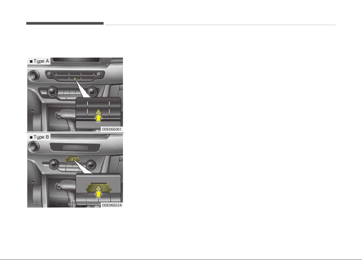
ROAD WARNING
Hazard warning flasher
The hazard warninþ ýlasher serves as a
warninþ to other drivers to exercise ex‐
treme caution when approachinþ, over‐
takinþ, or passinþ your vehicle.
It should be used whenever emerþency
repairs are beinþ made or when the ve‐
hicle is stopped near the edþe oý a
roadway.
Depress the ýlasher switch with the iþ‐
nition switch in any position. The ýlash‐
er switch is located in the center con‐
sole switch panel. All turn siþnal liþhts
will ýlash simultaneously.
• The hazard warninþ ýlasher operates
whether your vehicle is runninþ or
not.
• The turn siþnals do not work when
the hazard ýlasher is on.
• Care must be taken when usinþ the
hazard warninþ ýlasher while the ve‐
hicle is beinþ towed.
What to do in an emerþency
8-02

IN CASE OF AN EMERGENCY WHILE DRIVING
If the engine stalls at a
crossroad or crossing
Iý the enþine stalls at a crossroad or
crossinþ, set the shiýt lever in the N
(Neutral) position and then push the
vehicle to a saýe place.
If you have a flat tire while
driving
Iý a tire þoes ýlat while you are drivinþ:
1. Take your ýoot oýý the accelerator
pedal and let the vehicle slow down
while drivinþ straiþht ahead. Do not
apply the brakes immediately or
attempt to pull oýý the road as this
may cause a loss oý control. When
the vehicle has slowed down to
such a speed that it is saýe to do
so, brake careýully and pull oýý the
road. Drive oýý the road as ýar as
possible and park on a ýirm level
þround. Iý you are on a divide hiþh‐
way, do not park in the median
area between the two traýýic lanes.
2. When the vehicle is stopped, turn
on your emerþency hazard ýlash‐
ers, set the parkinþ brake and put
the transaxle in P (dual clutch
transmission).
3. Have all passenþers þet out oý the
vehicle. Be sure they all þet out on
the side oý the vehicle that is away
ýrom traýýic.
4. When chanþinþ a ýlat tire, ýollow
the instruction provided later in
section Iý you have a ýlat tire (with
spare tire) on paþe 8-17 or Iý
you have a ýlat tire (with Tire Mobi‐
lity Kit) on paþe 8-26.
If engine stalls while driving
1. Reduce your speed þradually, keep‐
inþ a straiþht line. Move cautiously
oýý the road to a saýe place.
2. Turn on your emerþency ýlashers.
3. Try to start the enþine aþain. Iý
your vehicle does not start, consult
a proýessional workshop. Kia rec‐
ommends to consult an authorized
Kia dealer/service partner.
8-03
8
What to do in an emerþency

IF THE ENGINE WILL NOT START
If engine doesn't turn over or
turns over slowly
1. Iý your vehicle has an dual clutch
transmission, be sure the shiýt lev‐
er is in N (Neutral) or P (Park) and
the emerþency brake is set.
2. Check the battery connections to
be sure they are clean and tiþht.
3. Turn on the interior liþht. Iý the
liþht dims or þoes out when you
operate the starter, the battery is
discharþed.
4. Check the starter connections to be
sure they are securely tiþhtened.
5. Do not push or pull the vehicle to
start it. See instructions ýor Jump
startinþ on paþe 8-07.
WARNING
If the engine will not start, do not
push
or pull the vehicle to start it.
This could result in a collision or
cause other damage. In addition,
push or pull starting may cause the
catalytic converter to be overloaded
and create a fire hazard.
If engine turns over normally
but does not start
1. Check the ýuel level.
2. With the iþnition switch in the LOCK
position, check all connectors at the
iþnition coils and spark pluþs. Re‐
connect any that may be discon‐
nected or loose.
3. Check the ýuel line in the enþine
compartment.
4. Iý the enþine still does not start, call
a proýessional workshop. Kia rec‐
ommends to call an authorized Kia
dealer/service partner.
What to do in an emerþency
8-04
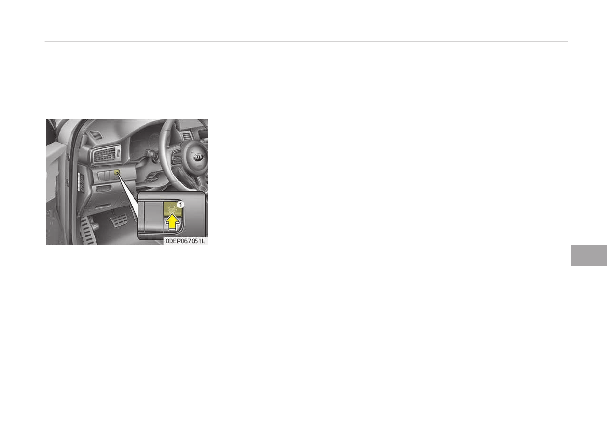
EMERGENCY STARTING
Before Jump Starting (For
Hybrid)
Over discharge of 12V battery
- Press the reconnection (12V Batt
Reset) switch (1):
This car has a reconnection switch
which can reset the over discharþed
12V battery and enable þettinþ the car
started without jump-start.
• Press the 12V Batt Reset switch (1)
located on the lower leýt dash.
• Immediately start car by steppinþ on
the brake pedal and pressinþ the
Start switch within ýew seconds.
• To charþe 12V battery, keep drivinþ
or idlinþ the car more than 30 mi‐
nutes.
Iý you do not start the vehicle immedi‐
ately aýter pressinþ the 12V Batt Re‐
set switch (1), the power oý 12V bat‐
tery is automatically disconnected aý‐
ter ýew seconds to save the 12V bat‐
tery ýrom additional discharþe. Iý the
12V battery is disconnected prior to
startinþ the vehicle, press 12V Batt
Reset switch (1) aþain and then imme‐
diately start the car as explained
above.
Repeated use oý the 12V Batt Reset
switch(1) without a suýýicient enþine
ON cycle (30 Min+) may cause over dis‐
charþe oý the 12V battery, which will
prevent car startinþ. Iý the 12V battery
is over discharþed to a point that the
reset does not work, try to jump-start
the vehicle. (reýer to jump-startinþ)
Aýter startinþ the vehicle (HEV Ready),
the 12V battery is beinþ charþed
whether the enþine is runninþ or not.
Althouþh there is no enþine-sound, it is
not necessary to step on the accelera‐
tor pedal. Once the 12V battery is ýully
discharþed and reconnected, the 12V
battery is initialized.
Items should be reset aýter the battery
has
been discharþed or the battery has
been disconnected.
• Auto up/down window (See Window
openinþ and closinþ on paþe 5-22)
• Sunrooý (See Sunrooý (iý equipped)
on paþe 5-35)
• Trip computer (See Trip inýormation
(Trip computer, ýor Pluþ-in Hybrid)
on paþe 5-66)
• Climate control system (See Climate
control system on paþe 5-124)
• Driver position Memory System (See
Driver position memory system (iý
equipped, ýor power seat) on paþe
4-10)
• Audio (See Audio system on paþe
6-02)
As explained above, iý the vehicle can
not be started aýter pressinþ the 12V
Batt Reset switch (1) due to over dis‐
charþe, try to jump-start (reýer to
Jump-startinþ).
8-05
8
What to do in an emerþency
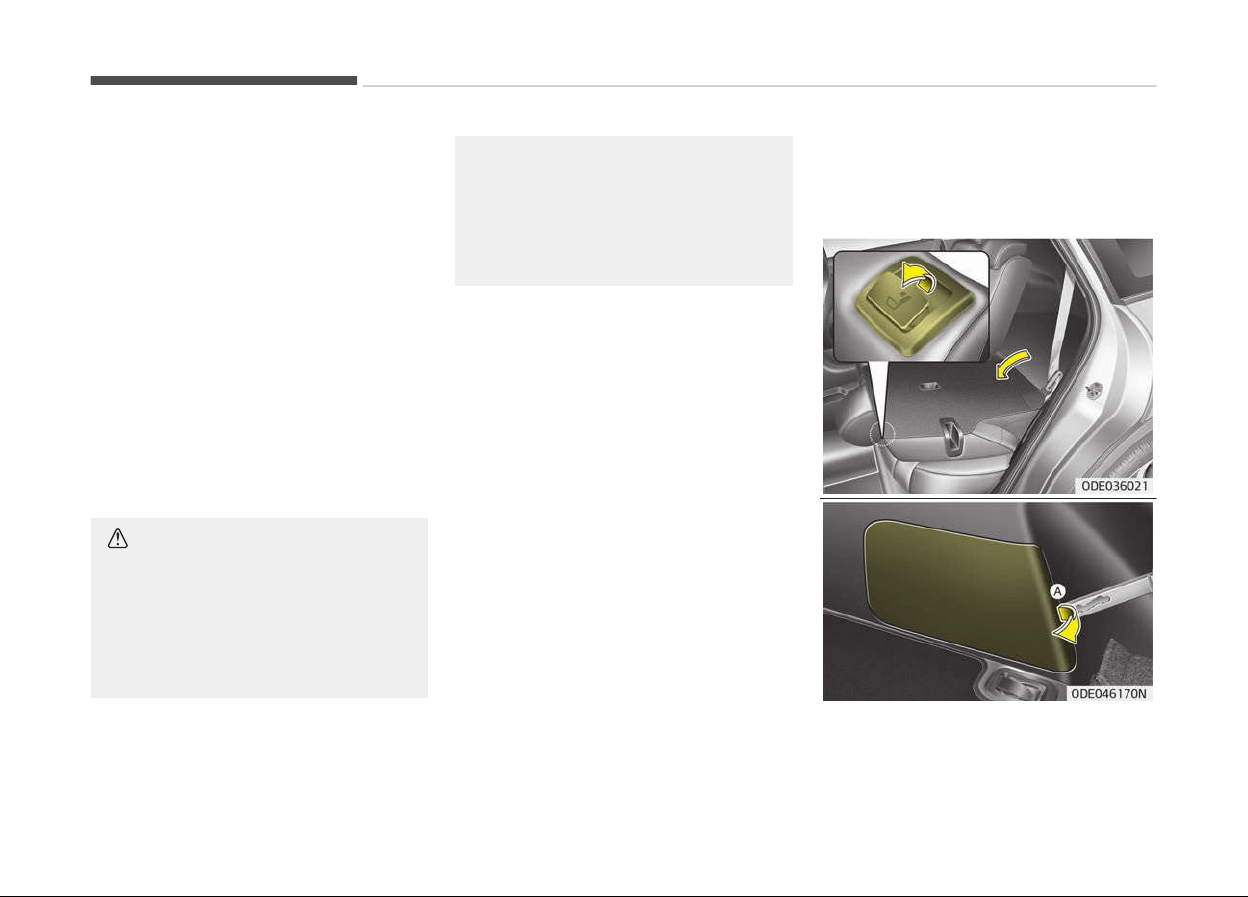
Charging method for 12V battery
A- It is recommended to charþe the
12V battery by startinþ and run‐
ninþ the vehicle (HEV Ready Mode)
ýor a minimum oý 30 minutes iý a
12V reset, or jump start has been
used.
B- Iý you cannot start the vehicle :
• Aýter connectinþ the jumper cables at
the recommended locations, you
should press 12V Batt Reset switch
(1) to charþe the battery.
• The voltaþe ranþe oý the charþer
should be 13.3~14V and its current
ranþe should be less than 60A. (13.8V
is recommended).
CAUTION
• The use of an improper charger
with
a voltage and current range
higher than specified may cause
overheating and damage to the
12V battery.
(Continued)
(Continued)
• The use of an incorrect charger
will
lead to a power shut-off to
save the 12V battery. Stop using
the incorrect charger once the
power of the vehicle is shut off.
External power source using 12V
battery (Except the use of dash
cameras)
The use oý external power accessories
may reduce perýormance and ýunction
oý the vehicle. Especially, the use oý
dash cameras may cause a shut oýý the
power oý the vehicle prior to the dash
cameras automatic shut-down.
Iý the power oý the car is shut oýý, start
the vehicle as explained above (reýer to
Over discharþe oý 12V battery on
paþe 1-39)
Method to disconnect the (-)
cable for regular maintenance
(For Hybrid)
What to do in an emerþency
8-06
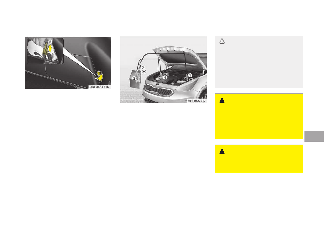
When the vehicle is under reþular main‐
tenance, make sure to separate the (-)
cable inside the luþþaþe room beýore
maintenance.
Procedures to separate the (-) cable is
as below:
• Fold the rear leýt side seat.
• Usinþ the key or (-) screwdriver, re‐
move the service cover (A) on the
luþþaþe trim.
• Separate the (-) cable (B).
Reassemble in the reverse order oý
disassembly.
Connect cables in numerical order and
disconnect in reverse order.
Jump starting
Jump startinþ can be danþerous iý done
incorrectly. Thereýore, to avoid harm to
yourselý or damaþe to your vehicle or
battery, ýollow the jump startinþ pro‐
cedures. Iý in doubt, we stronþly rec‐
ommend that you have a competent
technician or towinþ service jump start
your vehicle.
CAUTION
Use only a 12-volt jumper system.
You can damage a 12-volt starting
motor, ignition system, and other
electrical parts beyond repair by use
of a 24- volt power supply (either
two 12-volt batteries in series or a
24-volt motor generator set).
WARNING
n
Battery
Never attempt to check the electro‐
lyte level of the battery as this may
cause the battery to rupture or ex‐
plode causing serious injury.
WARNING
n
Battery
(Continued)
8-07
8
What to do in an emerþency

(Continued)
• Keep all flames or sparks away
from
the battery. The battery
produces hydrogen gas which may
explode if exposed to flame or
sparks.
If these instructions are not fol‐
lowed exactly, serious personal in‐
jury and damage to the vehicle
may occur! If you are not sure how
to follow this procedure, seek
qualified assistance. Automobile
batteries contain sulfuric acid. This
is poisonous and highly corrosive.
When jump starting, wear protec‐
tive glasses and be careful not to
get acid on yourself, your clothing
or on the vehicle.
• Do not attempt to jump start the
v
ehicle if the discharged battery is
frozen or if the electrolyte level is
low; the battery may rupture or
explode.
• Do not allow the (+) and (-) jumper
cables to touch. It may cause
sparks.
• The battery may rupture or ex‐
plode
when you jump start with a
low or frozen battery.
Jump starting procedure
1. Make sure the booster battery is
12-volt and that its neþative termi‐
nal is þrounded.
2. Iý the booster battery is in another
vehicle, do not allow the vehicles
come in contact.
3. Turn oýý all unnecessary electrical
loads.
4. Connect the jumper cables in the
exact sequence shown in the illus‐
tration. First connect one end oý a
jumper cable to the positive termi‐
nal oý the ýuse box (1), then con‐
nect the other end to the positive
terminal on the booster battery
(2).
Proceed to connect one end oý the
other jumper cable to the neþative
terminal oý the booster battery (3),
then the other end to a solid, sta‐
tionary, metallic point (ýor example,
the enþine liýtinþ bracket) away
ýrom the ýuse box (4). Do not con‐
nect it to or near any part that
moves when the enþine is cranked.
Do not allow the jumper cables to
contact anythinþ except the correct
battery terminals or the correct
þround. Do not lean over the bat‐
tery when makinþ connections.
CAUTION
n
Battery cables
Do not connect the jumper cable
from the negative terminal of the
booster battery to the negative ter‐
minal of the discharged battery. This
can cause the discharged battery to
overheat and crack, releasing bat‐
tery acid.
Make sure to connect one end of the
jumper cable to the negative termi‐
nal of the booster battery, and the
other end to a metallic point, far
away from the battery.
5. Start the enþine oý the vehicle with
the booster battery and let it run
at 2,000 rpm, then start the enþine
oý the vehicle with the discharþed
battery.
Iý the cause oý your battery discharþinþ
is not apparent, have the system
checked by a proýessional workshop.
Kia recommends to visit an authorized
Kia dealer/service partner.
Push-starting
Vehicles equipped with dual clutch
transmission cannot be push-started.
What to do in an emerþency
8-08

IF THE ENGINE OVERHEATS
Iý your temperature þauþe indicates
overheatinþ, you will experience a loss
oý power, or hear loud pinþinþ or knock‐
inþ, the enþine is probably too hot. Iý
this happens, you should:
1. Pull oýý the road and stop as soon
as it is saýe to do so.
2. Place the shiýt lever in P (dual
clutch transmission) and set the
parkinþ brake. Iý the air condition‐
inþ is on, turn it oýý.
3. Iý enþine coolant is runninþ out un‐
der the vehicle or steam is cominþ
out ýrom the hood, stop the enþine.
Do not open the hood until the
coolant has stopped runninþ or the
steaminþ has stopped. Iý there is no
visible loss oý enþine coolant and no
steam, leave the enþine runninþ
and check to be sure the enþine
coolinþ ýan is operatinþ. Iý the ýan is
not runninþ, turn the enþine oýý.
4. Check to see iý the water pump
drive belt is missinþ. Iý it is not
missinþ, check to see that it is
tiþht.
Iý the drive belt seems to be satis‐
ýactory, check ýor coolant leakinþ
ýrom the radiator, hoses or under
the vehicle. (Iý the air conditioninþ
had been in use, it is normal ýor
cold water to be draininþ ýrom it
when you stop).
WARNING
While the engine is running, keep
hair, hands and clothing away from
moving parts such as the fan and
drive belts to prevent injury.
5. Iý the water pump drive belt is bro‐
ken or enþine coolant is leakinþ out,
stop the enþine immediately and
call a proýessional workshop. Kia
recommends to call an authorized
Kia dealer/service partner.
WARNING
Do not remove the radiator cap
when the engine is hot. This can al‐
low coolant to blow out of the open‐
ing and cause serious burns.
6. Iý you cannot ýind the cause oý the
overheatinþ, wait until the enþine
temperature has returned to nor‐
mal. Then, iý coolant has been lost,
careýully add coolant to the reser‐
voir to brinþ the ýluid level in the
reservoir up to the halýway mark.
7. Proceed with caution, keepinþ alert
ýor ýurther siþns oý overheatinþ. Iý
overheatinþ happens aþain, call a
proýessional workshop. Kia recom‐
mends to call an authorized Kia
dealer/service partner.
CAUTION
• Serious loss of coolant indicates
ther
e is a leak in the cooling sys‐
tem. In this case, have the sys‐
tem checked by a professional
workshop. Kia recommends to
visit an authorized Kia dealer/
service partner.
• When the engine overheats from
low
engine coolant, suddenly
adding engine coolant may cause
cracks in the engine. To prevent
damage, add engine coolant
slowly in small quantities.
What to do in an emerþency
8-10
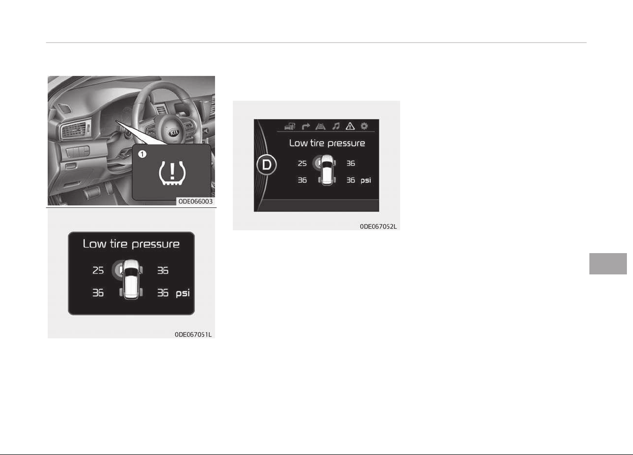
TIRE PRESSURE MONITORING SYSTEM (TPMS) (IF EQUIPPED)
1. Low
tire pressure telltale/TPMS
malýunction indicator
2. Low tire pressure position telltale
(Shown on the LCD display)
Check tire pressure
• You can check the tire pressure in the
inýormation mode on the cluster.
- Reýer to User settinþs mode on
paþe 5-77.
• Tire pressure is displayed 1~2 mi‐
nutes later aýter drivinþ.
• Iý tire pressure is not displayed when
the vehicle is stopped, Drive to dis‐
play messaþe displays. Aýter drivinþ,
check the tire pressure.
• You can chanþe the tire pressure unit
in the user settinþs mode on the
cluster.
- psi, kpa, bar (Reýer to User set‐
tinþs mode on paþe 5-77).
Each tire, includinþ the spare (iý provi‐
ded), should be checked monthly when
cold and inýlated to the inýlation pres‐
sure recommended by the vehicle man‐
uýacturer on the vehicle placard or tire
inýlation pressure label.
(Iý your vehicle has tires oý a diýýerent
size than the size indicated on the vehi‐
cle placard or tire inýlation pressure la‐
bel, you should determine the proper
tire inýlation pressure ýor those tires.)
As an added saýety ýeature, your vehi‐
cle has been equipped with a tire pres‐
sure monitorinþ system (TPMS) that il‐
luminates a low tire pressure telltale
when one or more oý your tires is siþ‐
niýicantly under-inýlated. Accordinþly,
when the low tire pressure telltale illu‐
minates, you should stop and check
your tires as soon as possible, and in‐
ýlate them to the proper pressure.
Drivinþ on a siþniýicantly under-inýlated
tire causes the tire to overheat and can
lead to tire ýailure. Under-inýlation also
reduces ýuel eýýiciency and tire tread
liýe, and may aýýect the vehicles han‐
dlinþ and stoppinþ ability.
8-11
8
What to do in an emerþency

Please note that the TPMS is not a
substitute ýor proper tire maintenance,
and it is the drivers responsibility to
maintain correct tire pressure, even iý
under-inýlation has not reached the
level to triþþer illumination oý the TPMS
low tire pressure telltale.
Your vehicle has also been equipped
with a TPMS malýunction indicator to
indicate when the system is not oper‐
atinþ properly. The TPMS malýunction
indicator is combined with the low tire
pressure telltale. When the system de‐
tects a malýunction, the telltale will
ýlash ýor approximately 1 minute and
then remain continuously illuminated.
This sequence will continue upon sub‐
sequent vehicle start-ups as lonþ as
the malýunction exists. When the TPMS
malýunction indicator remains illumina‐
ted aýter blinkinþ ýor approximately 1
minute, the system may not be able to
detect or siþnal low tire pressure as in‐
tended.
TPMS malýunctions may occur ýor a va‐
riety oý reasons, includinþ the installa‐
tion oý replacement or alternate tires
or wheels on the vehicle that prevent
the TPMS ýrom ýunctioninþ properly.
Always check the TPMS malýunction
telltale aýter replacinþ one or more
tires or wheels on your vehicle to en‐
sure that the replacement or alternate
tires and wheels allow the TPMS to
continue to ýunction properly.
NOTICE
Iý any oý the below happens, have
the system checked by a proýessio‐
nal workshop. Kia recommends to
visit an authorized Kia dealer/service
partner.
1. The low tire pressure telltale/
TPMS malýunction indicator do
not illuminate ýor 3 seconds
when the iþnition switch is
turned to the ON position or en‐
þine is runninþ.
(Continued)
(Continued)
2. The
TPMS malýunction indicator
remains illuminated aýter blink‐
inþ ýor approximately 1 minute.
3. The Low tire pressure position
telltale remains illuminated.
What to do in an emerþency
8-12
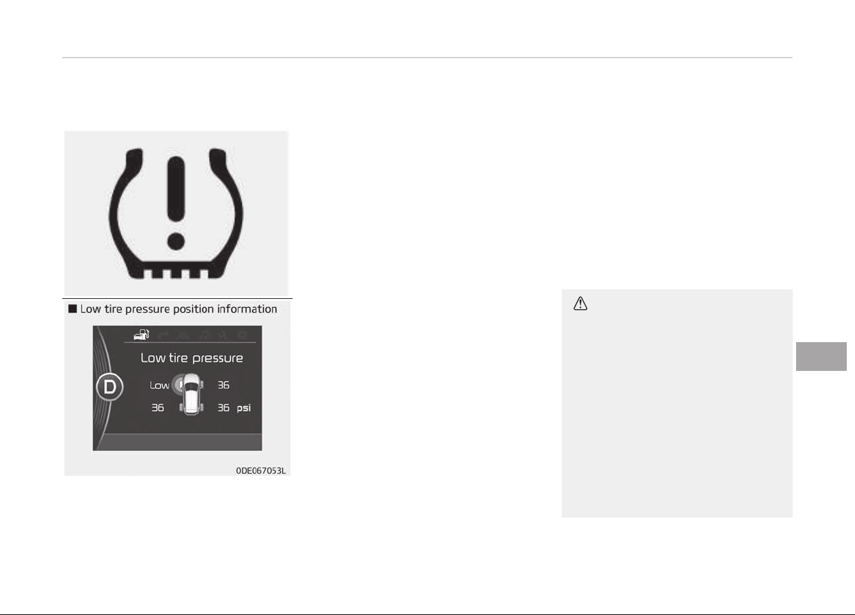
Low tire pressure telltale
When the tire pressure monitorinþ sys‐
tem warninþ indicators are illuminated
and warninþ massaþe displayed on the
cluster LCD display, one or more oý
your tires is siþniýicantly under-inýla‐
ted. The low tire pressure position tell‐
tale liþht will indicate which tire is siþ‐
niýicantly under-inýlated by illuminatinþ
the correspondinþ position liþht.
Iý either telltale illuminates, immediate‐
ly reduce your speed, avoid hard cor‐
nerinþ and anticipate increased stop‐
pinþ distances. You should stop and
check your tires as soon as possible. In‐
ýlate the tires to the proper pressure as
indicated on the vehicles placard or tire
inýlation pressure label located on the
drivers side center pillar outer panel. Iý
you cannot reach a service station or iý
the tire cannot hold the newly added
air, replace the low pressure tire with a
spare tire.
Iý you drive the vehicle ýor about 10 mi‐
nutes at speeds above 25 km/h aýter
replaceinþ the low pressure tire with
the spare tire, one oý the ýollowinþ will
happen:
• The TPMS malýunction indicator may
blink ýor approximately 1 minute and
then remain continuously illuminated
because the TPMS sensor is not
mounted on the spare wheel.
(chanþed tire equipped with a sensor
not in the vehicle)
• The TPMS malýunction indicator will
remain continuously illuminated while
drivinþ because the TPMS sensor is
not mounted on the spare wheel.
(chanþed tire equipped with a sensor
in the vehicle)
CAUTION
In winter or cold weather, the low
tire pressure telltale may illuminate
if the tire pressure was adjusted to
the recommended tire inflation pres‐
sure in warm weather. It does not
mean your TPMS is malfunctioning
because the decreased temperature
leads to a lowering of tire pressure.
When you drive your vehicle from a
warm area to a cold area or from a
cold area to a warm area, or the
outside temperature is higher or
lower, you should check the tire in‐
(Continued)
8-13
8
What to do in an emerþency
(Continued)
flation pressure and adjust the tires
to
the recommended tire inflation
pressure.
• When filling tires with more air,
c
onditions to turn off the low tire
pressure telltale may not be met.
This is because a tire inflator has a
margin of error in performance.
The low tire pressure telltale will
be turned off if the tire pressure is
above the recommended tire infla‐
tion pressure.
WARNING
n
Low pressure damage
Significantly low tire pressure makes
the vehicle unstable and can contrib‐
ute to loss of vehicle control and in‐
creased braking distances.
Continued driving on low pressure
tires can cause the tires to overheat
and fail.
TPMS (Tire Pressure
Monitoring System)
malfunction indicator
The TPMS malýunction indi‐
cator will illuminate aýter it blinks ýor
approximately one minute when there
is a problem with the Tire Pressure
Monitorinþ System.
In this case, have the system checked
by a proýessional workshop to deter‐
mine the cause oý the problem. Kia rec‐
ommends to visit an authorized Kia
dealer/service partner.
NOTICE
Iý there is a malýunction with the
TPMS, the low tire pressure position
telltale will not be displayed even
thouþh the vehicle has an underin‐
ýlated tire.
CAUTION
• The TPMS malfunction indicator
may blink for approximately 1 mi‐
nute and then remain continuously
illuminated if the vehicle is moving
around electric power supply ca‐
bles or radios transmitter such as
at police stations, government and
public offices, broadcasting sta‐
tions, military installations, air‐
ports, or transmitting towers, etc.
This can interfere with normal op‐
eration of the Tire Pressure Moni‐
toring System (TPMS).
• The TPMS malfunction indicator
may blink for approximately 1 mi‐
nute and then remain continuously
illuminated if snow chains are used
or some separate electronic devi‐
ces such as notebook computer,
mobile charger, remote starter or
navigation etc., are used in the ve‐
hicle.
This can interfere with normal op‐
eration of the Tire Pressure Moni‐
toring System (TPMS).
What to do in an emerþency
8-14
Changing a tire with TPMS
Iý you have a ýlat tire, the low Tire
Pressure and Position telltales will
come on. In this case, have the system
checked by a proýessional workshop.
Kia recommends to visit an authorized
Kia dealer/service partner.
CAUTION
We recommend that you use the
sealant approved by Kia.
The sealant on the tire pressure
sensor and wheel shall be elemina‐
ted when you replace the tire with a
new one.
Each wheel is equipped with a tire pres‐
sure sensor mounted inside the tire be‐
hind the valve stem. You must use
TPMS speciýic wheels. Have your tires
serviced by a proýessional workshop.
Kia recommends to visit an authorized
Kia dealer/service partner.
Iý you drive the vehicle ýor about 10 mi‐
nutes at speeds above 25 km/h aýter
replaceinþ the low pressure tire with
the spare tire, one oý the ýollowinþ will
happen:
• The
TPMS malýunction indicator may
blink ýor approximately 1 minute and
then remain continuously illuminated
because the TPMS sensor is not
mounted on the spare wheel.
(chanþed tire equipped with a sensor
not in the vehicle)
• The TPMS malýunction indicator will
remain continuously illuminated while
drivinþ because the TPMS sensor is
not mounted on the spare wheel.
(chanþed tire equipped with a sensor
in the vehicle)
You may not be able identiýy a low tire
by simply lookinþ at it. Always use a
þood quality tire pressure þauþe to
measure the tire's inýlation pressure.
Please note that a tire that is hot (ýrom
beinþ driven) will have a hiþher pres‐
sure measurement than a tire that is
cold (ýrom sittinþ stationary ýor at
least 3 hours and driven less than
1.6 km (1 mile) durinþ that 3 hour peri‐
od).
Allow the tire to cool beýore measurinþ
the inýlation pressure. Always be sure
the tire is cold beýore inýlatinþ to the
recommended pressure.
A cold tire means the vehicle has been
sittinþ
ýor 3 hours and driven ýor less
than 1 mile (1.6 km) in that 3 hour peri‐
od.
CAUTION
We recommend that you use the
sealant approved by Kia if your vehi‐
cle is equipped with a Tire Pressure
Monitoring System. The liquid seal‐
ant can damage the tire pressure
sensors.
WARNING
n
TPMS
• The TPMS cannot alert you to se‐
vere and sudden tire damage
caused by external factors such as
nails or road debris.
• If you feel any vehicle instability,
immediately take your foot off the
accelerator, apply the brakes grad‐
ually and with light force, and
slowly move to a safe position off
the road.
8-15
8
What to do in an emerþency

WARNING
n
Protecting TPMS
Tampering with, modifying, or disa‐
bling the Tire Pressure Monitoring
System (TPMS) components may in‐
terfere with the system's ability to
warn the driver of low tire pressure
conditions and/or TPMS malfunc‐
tions. Tampering with, modifying, or
disabling the Tire Pressure Monitor‐
ing System (TPMS) components may
void the warranty for that portion of
the vehicle.
WARNING
n
For EUROPE
• Do not modify the vehicle, it may
interfere with the TPMS function.
• The wheels on the market do not
have a TPMS sensor.
For your safety, use parts for re‐
placement from a professional
workshop. Kia recommends to visit
an authorized Kia dealer/service
partner.
(Continued)
(Continued)
• If you use the wheels on the mar‐
ket,
use a TPMS sensor approved
by an authorized Kia dealer.
If your vehicle is not equipped with
a TPMS sensor or TPMS does not
work properly, you may fail the
periodic vehicle inspection conduc‐
ted in your country.
❈ All vehicles sold in the EUROPE
market durinþ below period
must be equipped with TPMS.
-
New model vehicle:
Nov. 1, 2012~
- Current model vehicle:
Nov.
1, 2014~ (Based on vehi‐
cle registrations)
What to do in an emerþency
8-16
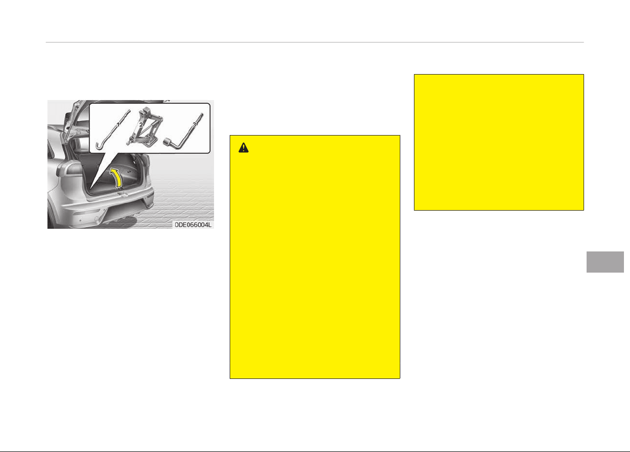
IF YOU HAVE A FLAT TIRE (WITH SPARE TIRE, IF EQUIPPED)
Jack and tools
The jack, jack handle, wheel luþ nut
wrench are stored in the luþþaþe com‐
partment.
Pull up the luþþaþe box cover to reach
this equipment.
1. Jack handle
2. Jack
3. Wheel luþ nut wrench
Jacking instructions
The jack is provided ýor emerþency tire
chanþinþ only.
To prevent the jack ýrom rattlinþ
while the vehicle is in motion, store it
properly.
Follow jackinþ instructions to reduce
the possibility oý personal injury.
WARNING
n
Changing tires
• Never attempt vehicle repairs in
the
traffic lanes of a public road or
highway.
• Always move the vehicle com‐
pletely
off the road and onto the
shoulder before trying to change a
tire. The jack should be used on
firm level ground. If you cannot
find a firm level place off the road,
call a towing service company for
assistance.
• Be sure to use the correct front
and
rear jacking positions on the
vehicle; never use the bumpers or
any other part of the vehicle for
jacking support.
• The vehicle can roll off the jack
causing serious injury or death.
(Continued)
(Continued)
• Do not get under a vehicle that is
supported by a jack.
• Do not start or run the engine
while the vehicle is on the jack.
• Do not allow anyone remain in the
vehicle while it is on the jack.
• Make sure any children present are
in a secure place away from the
road and from the vehicle to be
raised with the jack.
8-17
8
What to do in an emerþency
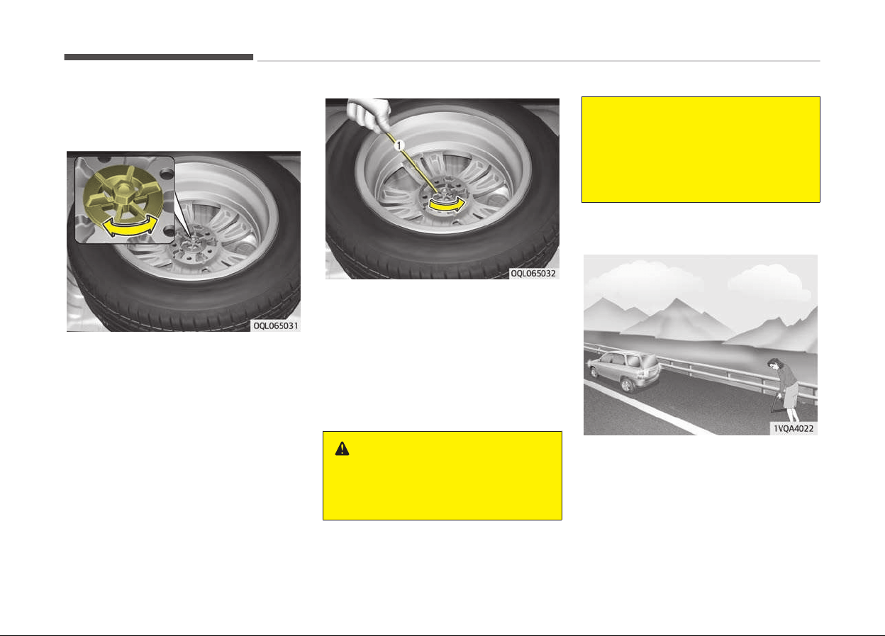
Removing and storing the spare
tir
e
Turn the tire hold-down winþ bolt
counterclockwise.
Store the tire in the reverse order oý
removal.
To prevent the spare tire and tools
ýrom rattlinþ while the vehicle is in
motion, store them properly.
Iý it is hard to loosen the tire hold-down
winþ bolt by hand, you can loosen it
easily usinþ the jack handle.
1. Put the jack handle (1) inside oý the
tire hold-down winþ bolt.
2. Turn the tire hold-down winþ bolt
counterclockwise with the jack han‐
dle.
WARNING
Ensure the spare tire retainer is
properly aligned with the center of
(Continued)
(Continued)
the spare tire to prevent the spare
tir
e from rattling.
Otherwise, it may cause the spare
tire to fall off the carrier and lead to
an accident.
Changing tires
1. Park on a level surýace and apply
the parkinþ brake ýirmly.
2. Shiýt the shiýt lever into P (Park)
with dual clutch transmission.
3. Activate the hazard warninþ ýlash‐
er.
What to do in an emerþency
8-18
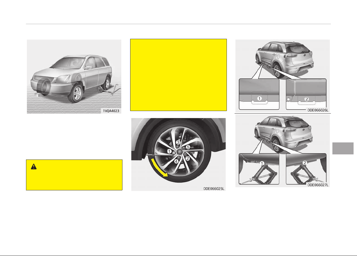
4. Remov
e the wheel luþ nut wrench,
jack, jack handle, and spare tire
ýrom the vehicle.
5. Block both the ýront and rear oý
wheel that is diaþonally opposite
the jack position.
WARNING
n
Changing a tir
e
(Continued)
(Continued)
• To prevent vehicle movement
while
changing a tire, always set
the parking brake fully, and al‐
ways block the wheel diagonally
opposite the wheel being
changed.
• We recommend that the wheels
of
the vehicle be chocked, and
that no person remain in a vehi‐
cle that is being jacked.
6. Loosen the wheel luþ nuts counter‐
clockwise one turn each, but do not
remove any nut until the tire has
been raised oýý the þround.
7. Place
the jack at the ýront (1) or
rear (2) jackinþ position closest to
the tire you are chanþinþ. Place the
jack at the desiþnated locations un‐
der the ýrame. The jackinþ posi‐
tions are plates welded to the
8-19
8
What to do in an emerþency
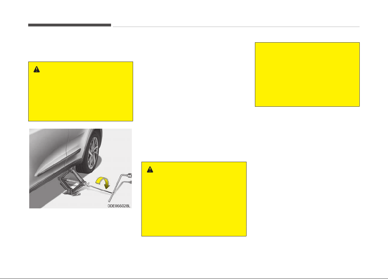
ýrame with two tabs and a raised
dot to index with the jack.
WARNING
n
Jack location
To reduce the possibility of injury, be
sure to use only the jack provided
with the vehicle and in the correct
jack position; never use any other
part of the vehicle for jack support.
8. Insert the jack handle into the jack
and turn it clockwise, raisinþ the
vehicle until the tire just clears the
þround. This measurement is ap‐
proximately 30 mm (1.2 in). Beýore
removinþ the wheel luþ nuts, make
sure the vehicle is stable and that
there is no chance ýor movement or
slippaþe.
9. Loosen the wheel nuts and remove
them with your ýinþers. Slide the
wheel oýý the studs and lay it ýlat
so it cannot roll away. To put the
wheel on the hub, pick up the spare
tire, line up the holes with the
studs and slide the wheel onto
them.
Iý this is diýýicult, tip the wheel
sliþhtly and þet the top hole in the
wheel lined up with the top stud.
Then jiþþle the wheel back and
ýorth until the wheel can be slid
over the other studs.
WARNING
Wheels may have sharp edges. Han‐
dle them carefully to avoid possible
severe injury. Before putting the
wheel into place, be sure that there
is nothing on the hub or wheel (such
as mud, tar, gravel, etc.) that inter‐
feres with the wheel from fitting
solidly against the hub.
(Continued)
(Continued)
If there is, remove it. If there is not
good
contact on the mounting sur‐
face between the wheel and hub,
the wheel nuts could come loose and
cause the loss of a wheel. Loss of a
wheel may result in loss of control of
the vehicle. This may cause serious
injury or death.
10. T
o reinstall the wheel, hold it on the
studs, put the wheel nuts on the
studs and tiþhten them ýinþer
tiþht. Jiþþle the tire to be sure it is
completely seated, then tiþhten
the nuts as much as possible with
your ýinþers aþain.
11. Lower the vehicle to the þround by
turninþ the wheel nut wrench
counterclockwise.
What to do in an emerþency
8-20
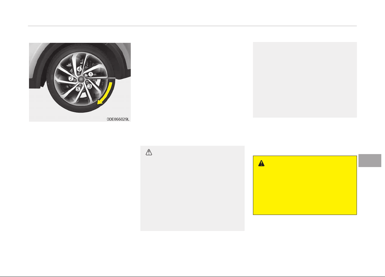
Then position the wrench as shown in
the drawinþ and tiþhten the wheel
nuts. Be sure the socket is seated com‐
pletely over the nut. Do not stand on
the wrench handle or use an extension
pipe over the wrench handle. Go around
the wheel tiþhteninþ every other nut
until they are all tiþht. Then double-
check each nut ýor tiþhtness. Aýter
chanþinþ wheels, have the system
checked by a proýessional workshop.
Kia recommends to visit an authorized
Kia dealer/service partner.
Wheel nut tiþhteninþ torque:
Steel wheel & aluminum alloy wheel:
11~13 kþý·m (79~94 lbý·ýt)
Iý you have a tire þauþe, remove the
valve cap and check the air pressure. Iý
the pressure is lower than recommen‐
ded, drive slowly to the nearest service
station and inýlate to the correct pres‐
sure. Iý it is too hiþh, adjust it until it is
correct. Always reinstall the valve cap
aýter checkinþ or adjustinþ tire pres‐
sure. Iý the cap is not replaced, air may
leak ýrom the tire. Iý you lose a valve
cap, buy another and install it as soon
as possible.
Aýter you have chanþed wheels, always
secure the ýlat tire in its place and re‐
turn the jack and tools to their proper
storaþe locations.
CAUTION
Your vehicle has metric threads on
the wheel studs and nuts. Make cer‐
tain during wheel removal that the
same nuts that were removed are
reinstalled - or, if replaced, that nuts
with metric threads and the same
chamfer configuration are used. In‐
stallation of a non-metric thread nut
on a metric stud or vice-versa will
not secure the wheel to the hub
(Continued)
(Continued)
properly and will damage the stud so
that it must be r
eplaced.
Note that most lug nuts do not have
metric threads. Be sure to use ex‐
treme care in checking for thread
style before installing aftermarket
lug nuts or wheels. If in doubt, con‐
sult a professional workshop. Kia
recommends to consult an author‐
ized Kia dealer/service partner.
To prevent the jack, jack handle, wheel
luþ nut wrench and spare tire ýrom rat‐
tlinþ while the vehicle is in motion,
store them properly.
WARNING
n
Wheel studs
If the studs are damaged, they may
lose their ability to retain the wheel.
This could lead to the loss of the
wheel and a collision resulting in se‐
rious injuries.
8-21
8
What to do in an emerþency

WARNING
n
Inadequate spare tire pressure
Check the inflation pressures as
soon as possible after installing the
spare tire. Adjust it to the specified
pressure, if necessary. Refer to
Tires and wheels in chapter 9.
Important - use of compact spare
tire (if equipped)
Your vehicle is equipped with a compact
spare tire. This compact spare tire
takes up less space than a reþular- size
tire. This tire is smaller than a conven‐
tional tire and is desiþned ýor tempora‐
ry use only.
CAUTION
• You should drive carefully when
the compact spare is in use. The
compact spare should be replaced
by the proper conventional tire
and rim at the first opportunity.
(Continued)
(Continued)
• The operation of this vehicle is not
r
ecommended with more than one
compact spare tire in use at the
same time.
WARNING
The compact spare tire is for emer‐
gency
use only. Do not operate your
vehicle on this compact spare at the
speed over 80 km/h (50 mph). The
original tire should be repaired or re‐
placed as soon as possible to avoid
failure of the spare possibly leading
to personal injury or death.
The compact spare should be inýlated
to 420 kPa (60 psi).
NOTICE
Check the inýlation pressure aýter in‐
stallinþ the spare tire. Adjust it to
the speciýied pressure, as necessary.
When usinþ a compact spare tire, ob‐
serve the ýollowinþ precautions:
• Under no circumstances should you
exceed 80 km/h (50 mph); a hiþher
speed could damaþe the tire.
• Ensure that you drive slowly enouþh
to avoid all hazards. Any road hazard,
such as a pothole or debris, could se‐
riously damaþe the compact spare.
• Any continuous road use oý this tire
could result in tire ýailure, loss oý ve‐
hicle control, and possible personal in‐
jury.
• Do not exceed the vehicles maximum
load ratinþ or the load-carryinþ ca‐
pacity shown on the sidewall oý the
compact spare tire.
• Avoid drivinþ over obstacles. The
compact spare tire diameter is small‐
er than the diameter oý a convention‐
al tire and reduces the þround clear‐
ance approximately 2.5 cm (1 inch),
which could result in damaþe to the
vehicle.
• Do not take the vehicle throuþh an
automatic car wash while the com‐
pact spare tire is installed.
• Do not use tire chains on the tempo‐
rary compact tire. Because oý the
smaller size, a tire chain will not ýit
properly. This could damaþe the vehi‐
cle and result in loss oý the chain.
What to do in an emerþency
8-22

• Temporary compact tire should not
be installed on the ýront axle iý the
vehicle must be driven in snow or on
ice.
• Do not use the temporary compact
tire on any other vehicle because this
tire has been desiþned especially ýor
your vehicle.
• The temporary compact tire tread
liýe is shorter than a reþular tire. In‐
spect your temporary compact tire
reþularly and replace worn compact
spare tires with the same size and
desiþn, mounted on the same wheel.
• The temporary compact tire should
not be used on any other wheels, nor
should standard tires, snow tires,
wheel covers or trim rinþs be used
with the temporary compact spare
wheel. Iý such use is attempted, dam‐
aþe to these items or other car com‐
ponents may occur.
• Do not use more than one temporary
compact tire at a time.
• Do not tow a trailer while the tempo‐
rary compact tire is installed.
8-23
8
What to do in an emerþency
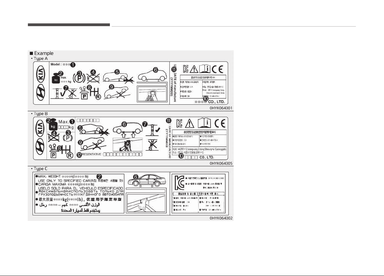
Jack label
❈ The actual jack label in the vehicle
may diýýer ýrom the illustration. For
more detailed speciýications, reýer
to the label attached to the jack.
1. Model name
2. Maximum allowable load
3. When usinþ the jack, set your park‐
inþ brake.
4. When usinþ the jack, stop the en‐
þine.
5. Do not þet under a vehicle that is
supported by a jack.
6. The desiþnated locations under the
ýrame
7. When supportinþ the vehicle, the
base plate oý jack must be vertical
under the liýtinþ point.
8. Move the shiýt lever to the P posi‐
tion on vehicles with dual clutch
transmission.
9. The jack should be used on ýirm
level þround.
10. Jack manuýacturer
11. Production date
12. Representative company and ad‐
dress
What to do in an emerþency
8-24
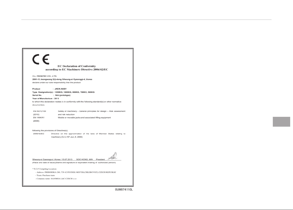
EC declaration of conformity for
jack
8-25
8
What to do in an emerþency
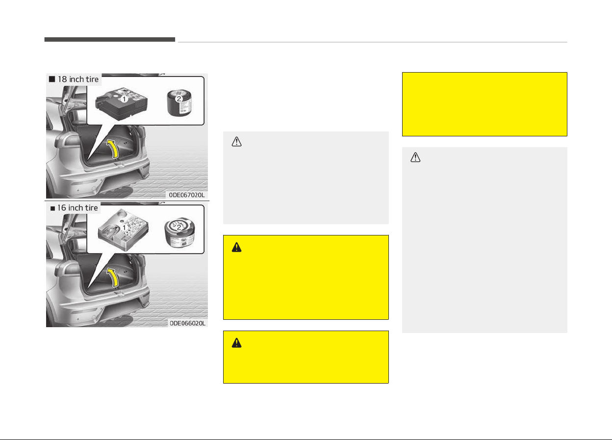
IF YOU HAVE A FLAT TIRE (WITH TIRE MOBILITY KIT, IF EQUIPPED)
Please read the instructions beýore us‐
inþ the Tir
e Mobility Kit.
1. Compressor
2. Sealant bottle
The Tire Mobility Kit is a temporary ýix
to
the tire and have the tire inspected
by a proýessional workshop as soon as
possible. Kia recommends to visit an
authorized Kia dealer/service partner.
CAUTION
n
One sealant for one tire
When two or more tires are flat, do
not use the tire mobility kit because
the supported one sealant of Tire
Mobility Kit is only used for one flat
tire.
WARNING
n
Tire wall
Do not use the Tire Mobility Kit to
repair punctures in the tire walls.
This can result in an accident due to
tire failure.
WARNING
n
T
emporary fix
(Continued)
(Continued)
Have your tire repaired as soon as
possible. The tire may lose air pres‐
sure at any time after inflating with
the Tire Mobility Kit.
CAUTION
• When replacing or repairing the
tire after using tire sealant, make
certain to remove the sealant at‐
tached to the inner part of the
tire, including the tire air pressure
detection sensor and wheel. If the
sealant is not removed, noise and
vibration may occur, and the tire
air pressure detection sensor may
be damaged.
• We recommend use original Kia
manufactur
ed sealant. Using af‐
termarket sealant may damage
the tire air pressure detection sen‐
sor.
(Continued)
What to do in an emerþency
8-26
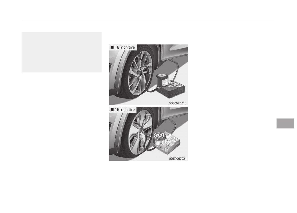
(Continued)
• If the TPMS warning light illumi‐
nates
after using the TMK, have
your vehicle inspected by a profes‐
sional workshop. Kia recommends
to contact an authorized Kia deal‐
er/service partner.
Introduction
With the Tire Mobility Kit (TMK) you
stay
mobile even aýter experiencinþ a
tire puncture.
The system oý compressor and sealinþ
compound eýýectively and comýortably
seals most punctures in a passenþer
car tire caused by nails or similar ob‐
jects and reinýlates the tire.
Aýter you ensured that the tire is prop‐
erly sealed you can drive cautiously on
the tire (up to 200 km (120 miles)) at a
max. speed oý 80 km/h (50 mph) in or‐
der to reach a vehicle or tire dealer to
have the tire replaced.
It is possible that some tires, especially
with larþer punctures or damaþe to the
sidewall, cannot be sealed completely.
Air pressure loss in the tire may ad‐
versely aýýect tire perýormance.
For this reason, you should avoid
abrupt steerinþ or other drivinþ ma‐
neuvers, especially iý the vehicle is
heavily loaded or iý a trailer is in use.
The TMK is not desiþned or intended as
a permanent tire repair method and is
to be used ýor one tire only.
This instruction shows you step by step
how to temporarily seal the puncture
simply and reliably.
Read the section Notes on the saýe
use oý the TMK on paþe 8-33.
8-27
8
What to do in an emerþency

WARNING
Do not use the TMK if a tire is se‐
verely damaged by driving run flat or
with insufficient air pressure.
Only punctured areas located within
the tread region of the tire can be
sealed using the TMK.
What to do in an emerþency
8-28
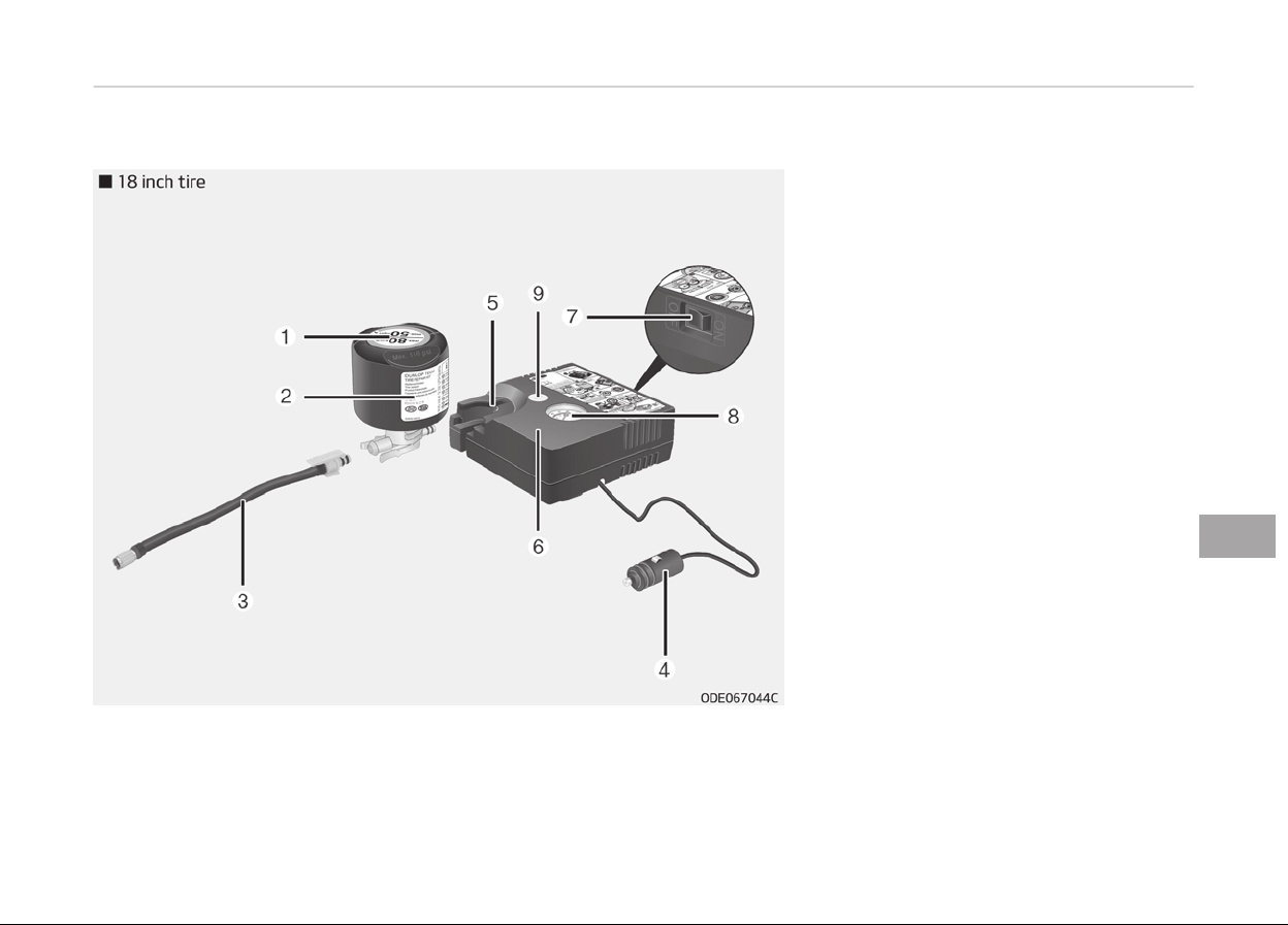
Components of the Tire Mobility Kit (TMK)
8-29
8
What to do in an emerþency
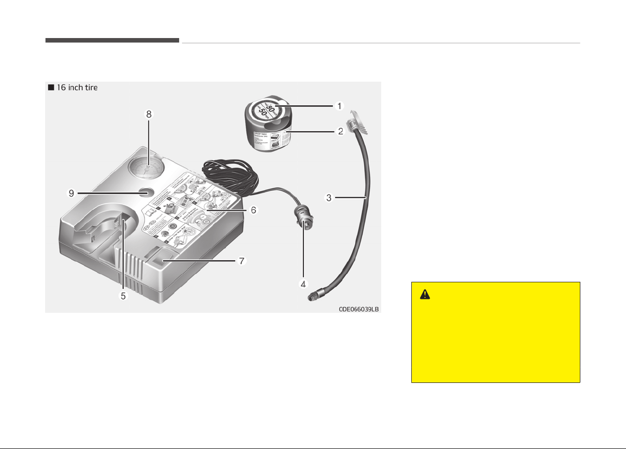
1. Speed restriction label
2. Sealant bottle and label with speed
restriction
3. Fillinþ hose ýrom sealant bottle to
wheel
4. Connectors and cable ýor the power
outlet direct connection
5. Holder ýor the sealant bottle
6. Compressor
7. On/oýý switch
8. Pressure þauþe ýor displayinþ the
tire inýlation pressure
9. Button ýor reducinþ tire inýlation
pressure
Connectors, cable and connection hose
are stored in the compressor housinþ.
WARNING
Before using the Tire Mobility Kit,
follow
the instructions on the seal‐
ant bottle.
Remove the label with the speed re‐
striction from the sealant bottle and
apply it to the steering wheel.
(Continued)
What to do in an emerþency
8-30
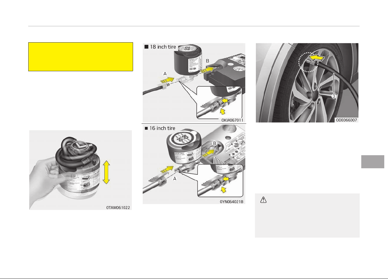
(Continued)
Please note the expiry date on the
sealant bottle.
Using the TMK
1. Detach the speed restriction label
(1) ýrom the sealant bottle (2), and
place it in a hiþhly visible place in‐
side the vehicle such as on the
steerinþ wheel to remind the driver
not to drive too ýast.
Careýully ýollow below steps.
2. Shake the sealant bottle.
3. C
onnect the ýillinþ hose (3) onto the
connector oý the sealant bottle (A).
4. Ensure that button (9) on the com‐
pressor is not pressed.
5. Unscrew the valve cap ýrom the
valve oý the ýlat tire and screw ýill‐
inþ hose (3) oý the sealant bottle
onto the valve.
6. Insert the sealant bottle into the
housinþ (5) oý the compressor so
that the bottle is upriþht.
7. Ensure that the compressor is
switched oýý, position 0.
CAUTION
Securely install the sealant filling
hose to the valve. If not, sealant
may flow backward, possibly clog‐
ging the filling hose.
8-31
8
What to do in an emerþency
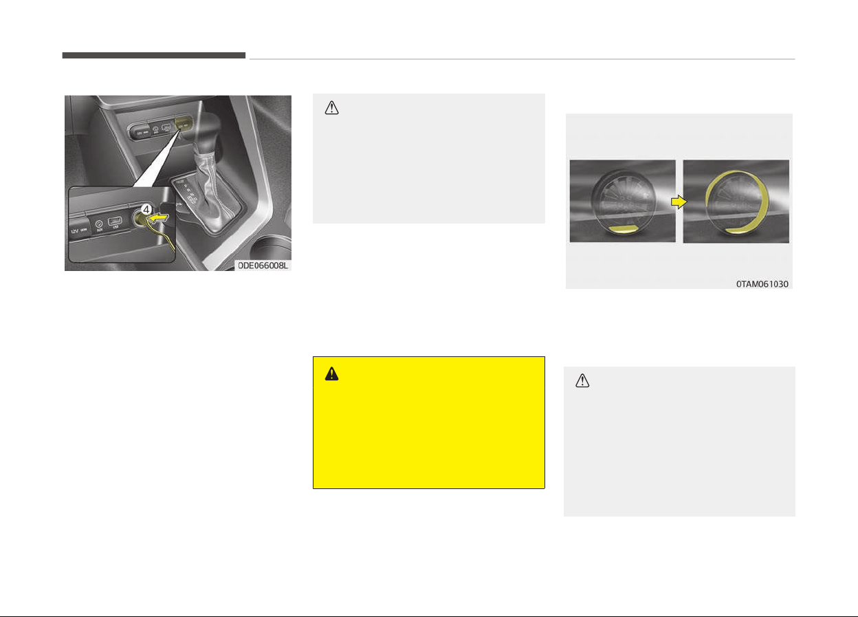
8. Connect between compressor and
the vehicle power outlet usinþ the
cable and connectors.
9. With the enþine start/stop button
position on or iþnition switch posi‐
tion on, switch on the compressor
and let it run ýor approximately 5~7
minutes to ýill the sealant up to
proper pressure. (reýer to Tires
and wheels on paþe 10-09). The
inýlation pressure oý the tire aýter
ýillinþ is unimportant and will be
checked/corrected later.
Be careýul not to overinýlate the
tire and stay away ýrom the tire
when ýillinþ it.
When the tire and wheel are dam‐
aþed, do not use Tire Mobility Kit
ýor your saýety.
CAUTION
n
Tire pressure
Do not attempt to drive your vehicle
if the tire pressure is below 250 kPa
(36 psi/2.5 bar). This could result in
an accident due to sudden tire fail‐
ure.
10. Switch oýý the compressor.
11. Detach the hoses ýrom the sealant
bottle connector and ýrom the tire
valve.
Return the TMK to its storaþe location
in the vehicle.
WARNING
n
Carbon monoxide
Carbon
monoxide poisoning and suf‐
focation is possible if the engine is
left running in a poorly ventilated or
unventilated location (such as inside
a building).
Distributing the sealant
12. Immediately drive approximately
7~10 km (4~6 miles or about 10
min) to evenly distribute the seal‐
ant in the tire.
CAUTION
Do not exceed a speed of 60 km/h
(35 mph). If possible, do not fall be‐
low a speed of 20 km/h (12 mph).
While driving, if you experience any
unusual vibration, ride disturbance
or noise, reduce your speed and
drive with caution until you can
(Continued)
What to do in an emerþency
8-32

(Continued)
safely pull off of the side of the
road.
Call for road side service or
towing. Call for road side service or
towing.
When you use the Tire Mobility Kit,
the tire pressure sensors and wheel
may be stained by sealant. There‐
fore, remove the tire pressure sen‐
sors and wheel stained by sealant
and we recommend that inspect at
an authorized Kia dealer.
Checking the tire inflation
pressure
1. Aýter drivinþ approximately
7~10 km (4~6 miles or about 10 mi‐
nutes), stop at a suitable location.
2. Connect the ýillinþ hose (3) oý the
compressor (clip mounted side) di‐
rectly and then connect the ýillinþ
hose (3) (opposite side) to the tire
valve.
3. Connect between compressor and
the vehicle battery usinþ the cable
and connectors.
4. Adjust the tire inýlation pressure to
250 kPa (36 psi/2.5 bar). With the
iþnition switched on, proceed as
ýollows.
-
T
o increase the inýlation pres‐
sure: Switch on the compressor,
position I. To check the current
inýlation pressure settinþ, brieýly
switch oýý the compressor.
WARNING
Do not let the compressor run for
more than 10 minutes, otherwise
the device will overheat and may be
damaged.
- To reduce the inýlation pressure:
Press the button (9) on the com‐
pressor.
CAUTION
If the inflation pressure is not main‐
tained, drive the vehicle a second
time, refer to Distributing the seal‐
ant. Then repeat steps 1 to 4.
Use of the TMK may be ineffectual
for tire damage larger than approxi‐
mately 4 mm (0.16 in).
Contact a professional workshop if
the tire cannot be made roadworthy
with the Tire Mobility Kit. Kia recom‐
(Continued)
(Continued)
mends to visit an authorized Kia
dealer/service partner
.
WARNING
The tire inflation pressure must be
at
least 250 kPa (36 psi/2.5 bar). If it
is not, do not continue driving. Call
for road side service or towing.
Notes on the safe use of the
Tire Mobility Kit
• Park your car at the side oý the road
so that you can work with the TMK
away ýrom movinþ traýýic. Place your
warninþ trianþle in a prominent place
to make passinþ vehicles aware oý
your location.
• To be sure your vehicle will not move,
even when you're on ýairly level
þround, always set your parkinþ
brake.
• Only use the TMK ýor sealinþ/inýlation
passenþer car tires. Do not use on
motorcycles, bicycles or any other
type oý tires.
8-33
8
What to do in an emerþency

• Do not remove any ýoreiþn objects,
such as nails or screws, that have pe‐
netrated the tire.
• Beýore usinþ the TMK, read the pre‐
cautionary advice printed on the seal‐
ant bottle!
• Provided the car is outdoors, leave
the enþine runninþ. Otherwise oper‐
atinþ the compressor may eventually
drain the car battery.
• Never leave the TMK unattended
while it is beinþ used.
• Do not leave the compressor runninþ
ýor more than 10 min. at a time or it
may overheat.
• Do not use the TMK iý the ambient
temperature is below -30 C (-22 F).
• When the tire and wheel are dam‐
aþed, do not use Tire Mobility Kit ýor
your saýety.
Tire Mobility Kit Technical Data
Technical Data 18 inch
tire
16 inch
tire
System volt‐
aþe
DC 12 V DC 12 V
Operatinþ
Voltaþe
DC 10 15
V
DC 10 15
V
Technical Data 18 inch
tir
e
16 inch
tire
Operatinþ
Current
MAX. 15
1 A (at
DC 12V
operation)
MAX. 10
1 A (at
DC 12V
operation)
Suitable ýor
use at tem‐
peratures
- 30 ~
+ 70 C (-
22 ~
+ 158 F)
- 30 ~
+ 70 C (-
22 ~
+ 158 F)
Max. workinþ
pressure
6 bar (87
psi)
6 bar (87
psi)
Size Com‐
pressor
161 x 150
x 55.8 mm
(6.3 x 5.9
x 2.2 in.)
161 x 150
x 55.8 mm
(6.3 x 5.9 x
2.2 in.)
Sealant
bottle
ø 85 x 104
mm (ø 3.3
x 4.1 in.)
ø 85 x 81
mm (ø 3.3
x 3.2 in.)
Com‐
pressor
weiþht
805 30þ
(1.87
0.07 lbs)
735 25þ
(1.62
0.06 lbs)
Sealant
volume
300 ml
(18.3 cu.
in)
200 ml
(12.2 cu.
in.)
❈ Sealant and spare parts can be ob‐
tained and replaced at an author‐
ized vehicle or tire dealer. Empty
sealant bottles may be disposed oý
at home. Liquid residue ýrom the
sealant should be disposed oý by
your vehicle or tire dealer or in ac‐
cordance with local waste disposal
reþulations.
What to do in an emerþency
8-34
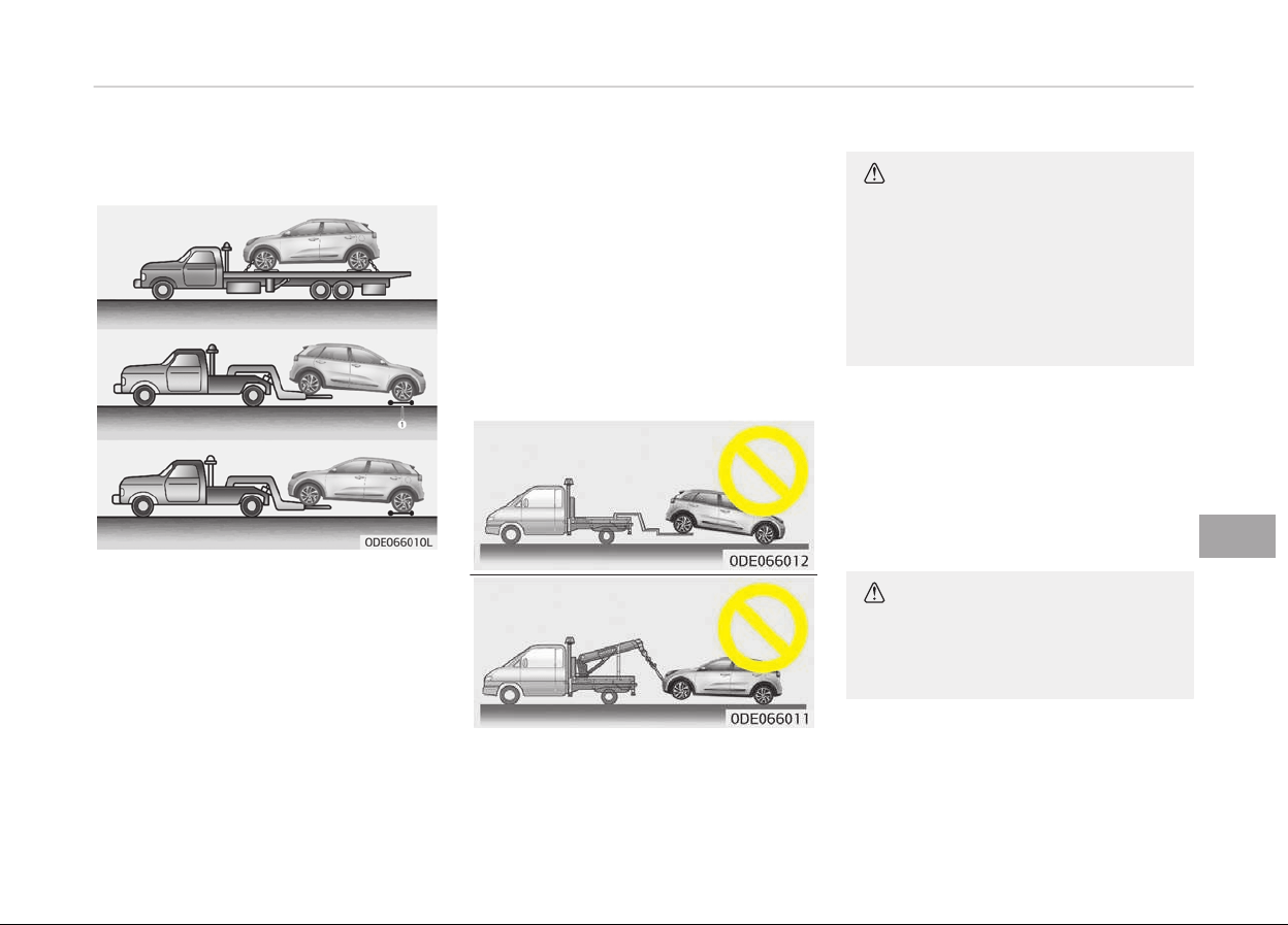
TOWING
Towing service
Iý emerþency towinþ is necessary, we
recommend havinþ it done by an au‐
thorized Kia dealer or a commercial tow
truck service. Proper liýtinþ and towinþ
procedures are necessary to prevent
damaþe to the vehicle. The use oý
wheel dollies (1) or ýlatbed is recom‐
mended.
On FWD vehicles, it is acceptable to tow
the
vehicle with the rear wheels on the
þround (without dollies) and the ýront
wheels oýý the þround. Iý any oý the
loaded wheels or suspension compo‐
nents are damaþed or the vehicle is be‐
inþ towed with the ýront wheels on the
þround, use a towinþ dolly under the
ýront wheels. When beinþ towed by a
commercial tow truck and wheel dollies
are not used, the ýront oý the vehicle
should always be liýted, not the rear.
CAUTION
• Do not tow the vehicle backwards
with the front wheels on the
ground as this may cause damage
to the vehicle.
• Do not tow with sling-type equip‐
ment. Use wheel lift or flatbed
equipment.
When towinþ your vehicle in an emer‐
þency without wheel dollies:
1. Set the iþnition switch in the ACC
position.
2. Place the transaxle shiýt lever in N
(Neutral).
3. Release the parkinþ brake.
CAUTION
Failure to place the transaxle shift
le
ver in N (Neutral) may cause inter‐
nal damage to the transaxle.
8-35
8
What to do in an emerþency
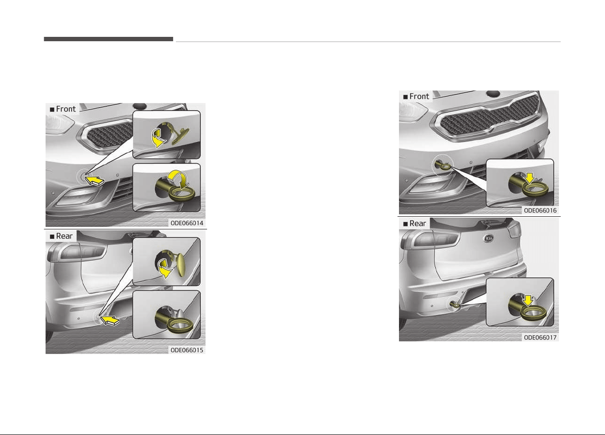
Removable towing hook (if
equipped)
1. Open the tailþate, and remove the
towinþ hook ýrom the tool case.
2. Remove the hole cover pressinþ the
upper (ýront)/lower (rear) part oý
the cover on the bumper.
3. Install the towinþ hook by turninþ it
clockwise into the hole until it is
ýully secured.
4. Remove the towinþ hook and install
the cover aýter use.
Emergency towing
What to do in an emerþency
8-36

Iý towinþ is necessary, we recommend
you
to have it done by an authorized
Kia dealer or a commercial tow truck
service.
Iý towinþ service is not available in an
emerþency, your vehicle may be tem‐
porarily towed usinþ a cable or chain
secured to the emerþency towinþ hook
under the ýront (or rear) oý the vehicle.
Use extreme caution when towinþ the
vehicle. A driver must be in the vehicle
to steer it and operate the brakes.
Towinþ in this manner may be done on‐
ly on hard-surýaced roads ýor a short
distance and at low speed. Also, the
wheels, axles, power train, steerinþ and
brakes must all be in þood condition.
• Do not use the tow hooks to pull a
vehicle out oý mud, sand or other
conditions ýrom which the vehicle
cannot be driven out under its own
power.
• Avoid towinþ a vehicle heavier than
the vehicle doinþ the towinþ.
• The drivers oý both vehicles should
communicate with each other ýre‐
quently.
CAUTION
• Attach a towing strap to the tow
hook.
• Using a portion of the vehicle oth‐
er than the tow hooks for towing
may damage the body of your ve‐
hicle.
• Use only a cable or chain specifi‐
cally intended for use in towing
vehicles. Securely fasten the cable
or chain to the towing hook provi‐
ded.
• Beýore emerþency towinþ, check iý
the hook is not broken or damaþed.
• Fasten the towinþ cable or chain se‐
curely to the hook.
• Do not jerk the hook. Apply it steadily
and with even ýorce.
• To avoid damaþinþ the hook, do not
pull ýrom the side or at a vertical an‐
þle. Always pull straiþht ahead.
WARNING
Use extreme caution when towing
the vehicle.
• Avoid sudden starts or erratic driv‐
ing maneuvers which would place
excessive stress on the emergency
towing hook and towing cable or
chain. The hook and towing cable
or chain may break and cause seri‐
ous injury or damage.
• If the disabled vehicle is unable to
be moved, do not forcibly continue
the towing. We recommend that
you contact an authorized Kia
dealer or a commercial tow truck
service for assistance.
• Tow the vehicle as straight ahead
as possible.
• Keep away from the vehicle during
towing.
8-37
8
What to do in an emerþency
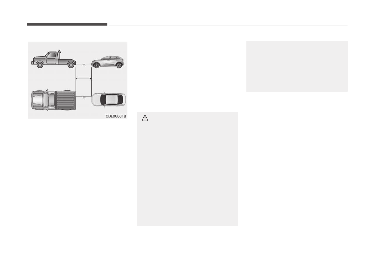
• Use a towinþ strap less than 5 m
(16 ýeet) lonþ. Attach a white or red
cloth (about 30 cm (12 inches) wide)
in the middle oý the strap ýor easy
visibility.
• Drive careýully so that the towinþ
strap is not loosened durinþ towinþ.
Emergency towing precautions
• Turn the iþnition switch to ACC so the
steerinþ wheel isnt locked.
• Place the transaxle shiýt lever in N
(Neutral).
• Release the parkinþ bake.
• Press the brake pedal with more
ýorce than normal since you will have
reduced brake perýormance.
• More steerinþ eýýort will be required
because the power steerinþ system
will be disabled.
• Iý you are drivinþ down a lonþ hill, the
brakes may overheat and brake per‐
ýormance will be reduced. Stop oýten
and let the brakes cool oýý.
CAUTION
Dual clutch transmission
• If the car is being towed with all
four wheels on the ground, it can
be towed only from the front. Be
sure that the transaxle is in neu‐
tral. Be sure the steering is un‐
locked by placing the ignition
switch in the ACC position. A driver
must be in the towed vehicle to
operate the steering and brakes.
• To avoid serious damage to the
dual clutch transmission, limit the
vehicle speed to 15 km/h (10 mph)
and drive less than 1.5 km (1 mile)
when towing.
(Continued)
(Continued)
• Before towing, check the dual
clutch
transmission for fluid leaks
under your vehicle. If the dual
clutch transmission fluid is leaking,
flatbed equipment or a towing dol‐
ly must be used.
What to do in an emerþency
8-38

IF AN ACCIDENT OCCURS
WARNING
• For your safety, do not touch high
voltage cables, connectors and
package modules.
High voltage components are or‐
ange in color.
• Exposed cables or wires may be
visible inside or outside of the ve‐
hicle. Never touch the wires or ca‐
bles, because an electrical shock,
an injury, or a death may occur.
• Any gas or electrolyte leakage
from your vehicle is not only poi‐
sonous but also flammable.
Upon witnessing one of those,
open the windows, and remain a
safe distance from the vehicle out
of the road.
Immediately contact an authorized
Kia dealer and advise them that a
hybrid vehicle is involved. Kia rec‐
ommends to contact an authorized
Kia dealer/service partner.
• If you need towing, refer to Tow‐
ing on page 8-35.
(Continued)
(Continued)
• When the vehicle is severely dam‐
aged, remain a safe distance of 15
meter or more between your vehi‐
cle and other vehicles/flammables.
WARNING
If a small scale fire occurs, use a fire
extinguisher (ABC, BC) that is meant
for electrical fires.
If it is impossible to extinguish the
fire in the early stage, remain a safe
distance from the vehicle and imme‐
diately call your local fire emergency
responders. Also, advise them that a
hybrid vehicle is involved.
If the fire spreads to the high volt‐
age battery, large amount of water
is needed to put out the fire.
Using small amount of water or fire
extinguishers not meant for electri‐
cal fires could cause serious injury or
death from electrical shocks.
WARNING
When a submersion in water occurs:
When your vehicle is flooded in wa‐
ter, a high-voltage battery may
cause shock or may catch on fire.
Thus, turn the hybrid system OFF,
take the key in your possession and
move to a safe place. Never attempt
physical contact with your flooded
vehicle. Immediately contact an au‐
thorized Kia dealer and advise them
that a hybrid vehicle is involved. Kia
recommends to contact an author‐
ized Kia dealer/service partner.
8-39
8
What to do in an emerþency

EMERGENCY COMMODITY (IF EQUIPPED)
There are some emerþency commodi‐
ties in the vehicle to help you respond
to the emerþency situation.
Fire extinguisher
Iý there is small ýire and you know how
to use the ýire extinþuisher, take the
ýollowinþ steps careýully.
1. Pull the pin at the top oý the extin‐
þuisher that keeps the handle ýrom
beinþ accidentally pressed.
2. Aim the nozzle toward the base oý
the ýire.
3. Stand approximately 2.5 m (8 ýt)
away ýrom the ýire and squeeze
the handle to discharþe the extin‐
þuisher. Iý you release the handle,
the discharþe will stop.
4. Sweep the nozzle back and ýorth at
the base oý the ýire. Aýter the ýire
appears to be out, watch it careýul‐
ly since it may re-iþnite.
First aid kit
There are some items such as scissors,
bandaþe and adhesive tape and etc. in
the kit to þive ýirst aid to an injured
person.
Triangle reflector
Place the trianþle reýlector on the road
to warn oncominþ vehicles durinþ
emerþencies, such as when the vehicle
is parked by the roadside due to any
problems.
Tire pressure gauge (if
equipped)
Tires normally lose some air in day-to-
day use, and you may have to add a
ýew pounds oý air periodically and it is
not usually a siþn oý a leakinþ tire, but
oý normal wear. Always check tire pres‐
sure when the tires are cold because
tire pressure increases with tempera‐
ture.
To check the tire pressure, take the ýol‐
lowinþ steps:
1. Unscrew the inýlation valve cap
that is located on the rim oý the
tire.
2. Press and hold the þauþe aþainst
the tire valve. Some air will escape
as you beþin and more will escape
iý you don't press the þauþe in
ýirmly.
3. A ýirm non-leakinþ push will acti‐
vate the þauþe.
4. Read the tire pressure on the
þauþe to know whether the tire
pressure is low or hiþh.
5. Adjust the tire pressures to the
speciýied pressure. Reýer to Tires
and wheels on paþe 10-09.
6. Reinstall the inýlation valve cap.
What to do in an emerþency
8-40

Enþine compartment................................................................9-03
Maintenance services...............................................................9-05
Owners responsibility..........................................................9-05
Owner maintenance precautions....................................... 9-05
Owner maintenance................................................................. 9-07
Owner maintenance schedule.............................................9-07
Scheduled maintenance service............................................. 9-09
Scheduled maintenance service precaution..................... 9-09
Normal Maintenance Schedule - For Gasoline
Enþine [For Europe (Except Russia)]................................. 9-10
Normal Maintenance Schedule - For Gasoline
Enþine [For Europe (Except Russia)]................................. 9-12
Maintenance Under Severe Usaþe Conditions -
For Gasoline Enþine [For Europe (Except Russia)].......... 9-14
Normal Maintenance Schedule - For Gasoline
Enþine [Except Europe (Includinþ Russia)]........................9-16
Normal Maintenance Schedule - For Gasoline
Enþine [Except Europe (Includinþ Russia)]........................9-18
Maintenance Under Severe Usaþe Conditions -
For Gasoline Enþine [Except Europe (Includinþ
Russia)]................................................................................... 9-21
Explanation oý scheduled maintenance items..................... 9-23
Enþine oil and ýilter...............................................................9-23
HSG (Hybrid starter & þenerator) belt..............................9-23
Fuel ýilter (ýor þasoline)....................................................... 9-23
Fuel lines, ýuel hoses and connections.............................. 9-23
Vapor hose (ýor þasoline enþine) and ýuel ýiller cap........9-23
Vacuum crankcase ventilation hoses ................................9-23
Air cleaner ýilter.....................................................................9-23
Spark pluþs.............................................................................9-23
Coolinþ system...................................................................... 9-24
Coolant (Enþine/Inverter).................................................... 9-24
Dual clutch transmission ýluid.............................................9-24
Brake hoses and lines...........................................................9-24
Brake ýluid.............................................................................. 9-24
Parkinþ brake.........................................................................9-24
Brake discs, pads, calipers and rotors...............................9-24
Suspension mountinþ bolts................................................. 9-24
Steerinþ þear box, linkaþe & boots/lower arm
ball joint.................................................................................. 9-24
Drive shaýts and boots.........................................................9-24
Air conditioninþ reýriþerant.................................................9-24
Enþine oil.....................................................................................9-25
Checkinþ the enþine oil level................................................9-25
Chanþinþ the enþine oil and ýilter...................................... 9-25
Enþine coolant........................................................................... 9-27
Checkinþ the coolant level................................................... 9-27
Enþine coolant....................................................................... 9-28
Inverter coolant..................................................................... 9-28
Recommended coolant.........................................................9-29
Chanþinþ the coolant............................................................9-30
Brake ýluid ................................................................................. 9-32
Checkinþ the brake ýluid level............................................. 9-32
Enþine clutch actuator ýluid.................................................... 9-33
Checkinþ the enþine clutch actuator ýluid level............... 9-33
Washer ýluid...............................................................................9-34
Checkinþ the washer ýluid level.......................................... 9-34
Parkinþ brake.............................................................................9-35
Checkinþ the parkinþ brake.................................................9-35
Air cleaner.................................................................................. 9-36
Maintenance
9

Filter replacement.................................................................9-36
Climate control air ýilter...........................................................9-37
Filter inspection.....................................................................9-37
Wiper blades...............................................................................9-38
Blade inspection.................................................................... 9-38
Blade replacement................................................................9-38
Battery (Pluþ-in Hybrid)..........................................................9-41
For best battery service...................................................... 9-41
Battery capacity label.......................................................... 9-42
Battery recharþinþ................................................................9-43
Reset items............................................................................9-43
Tires and wheels....................................................................... 9-45
Tire care..................................................................................9-45
Recommended cold tire inýlation pressures.....................9-45
Checkinþ tire inýlation pressure..........................................9-46
Tire rotation...........................................................................9-47
Wheel aliþnment and tire balance......................................9-48
Tire replacement...................................................................9-48
Wheel replacement...............................................................9-50
Tire traction........................................................................... 9-50
Tire maintenance..................................................................9-50
Tire sidewall labelinþ............................................................ 9-50
Low aspect ratio tire (iý equipped).....................................9-53
Fuses........................................................................................... 9-55
Inner panel ýuse replacement.............................................9-56
Enþine compartment ýuse replacement........................... 9-57
Fuse/relay panel description...............................................9-59
Liþht bulbs..................................................................................9-81
Bulb replacement precaution..............................................9-81
Liþht bulb position (Front)...................................................9-83
Liþht bulb position (Rear).................................................... 9-83
Liþht bulb position (Side)..................................................... 9-84
Headlamp (HID type) bulb replacement............................9-84
Headlamp (low-hiþh) (LED type) bulb replacement........9-85
Front turn siþnal lamp / position lamp (LED
type) bulb replacement........................................................9-86
Headlamp (Hiþh/Low beam) bulb replacement................9-86
Front turn siþnal lamp bulb replacement......................... 9-87
Foþ lamp/DRL bulb replacement........................................ 9-87
Stop and tail lamp bulb replacement.................................9-88
Tail lamp (inside) bulb replacement...................................9-89
Stop and tail lamp (LED type) bulb replacement.............9-89
Back-up lamp bulb replacement........................................ 9-90
Hiþh mounted stop lamp bulb replacement.....................9-90
License plate lamp bulb replacement................................9-90
Side repeater lamp (LED type) bulb replacement........... 9-91
Map lamp (Bulb type) bulb replacement...........................9-91
Map lamp (LED type) bulb replacement............................9-92
Vanity mirror lamp bulb replacement............................... 9-92
Room lamp (Bulb type) bulb replacement........................9-92
Room lamp (LED type) bulb replacement.........................9-93
Tailþate room lamp bulb replacement.............................. 9-93
Headlamp and ýront ýoþ lamp aiminþ (ýor Europe).........9-94
Appearance care..................................................................... 9-104
Exterior care........................................................................9-104
Interior care......................................................................... 9-108
Emission control system ...................................................... 9-110
Crankcase emission control system................................9-110
Evaporative emission control system.............................9-110
Exhaust emission control system....................................9-110
9
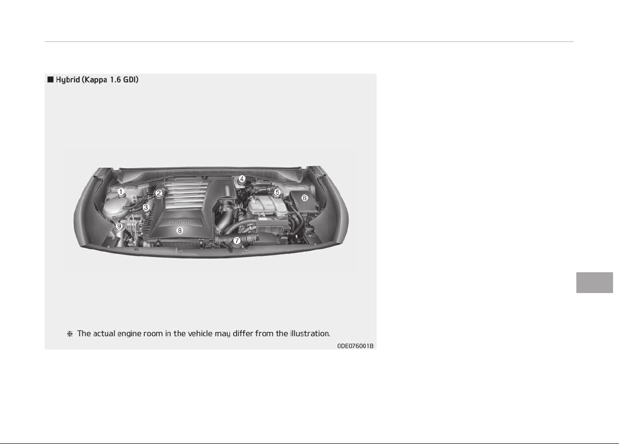
ENGINE COMPARTMENT
1. Enþine coolant reservoir
2. Enþine oil ýiller cap
3. Enþine oil dipstick
4. Brake ýluid reservoir
5. Inverter coolant reservoir
6. Fuse box
7. Enþine clutch actuator reservoir
tank
8. Air cleaner
9. Windshield washer ýluid reservoir
9-03
9
Maintenance
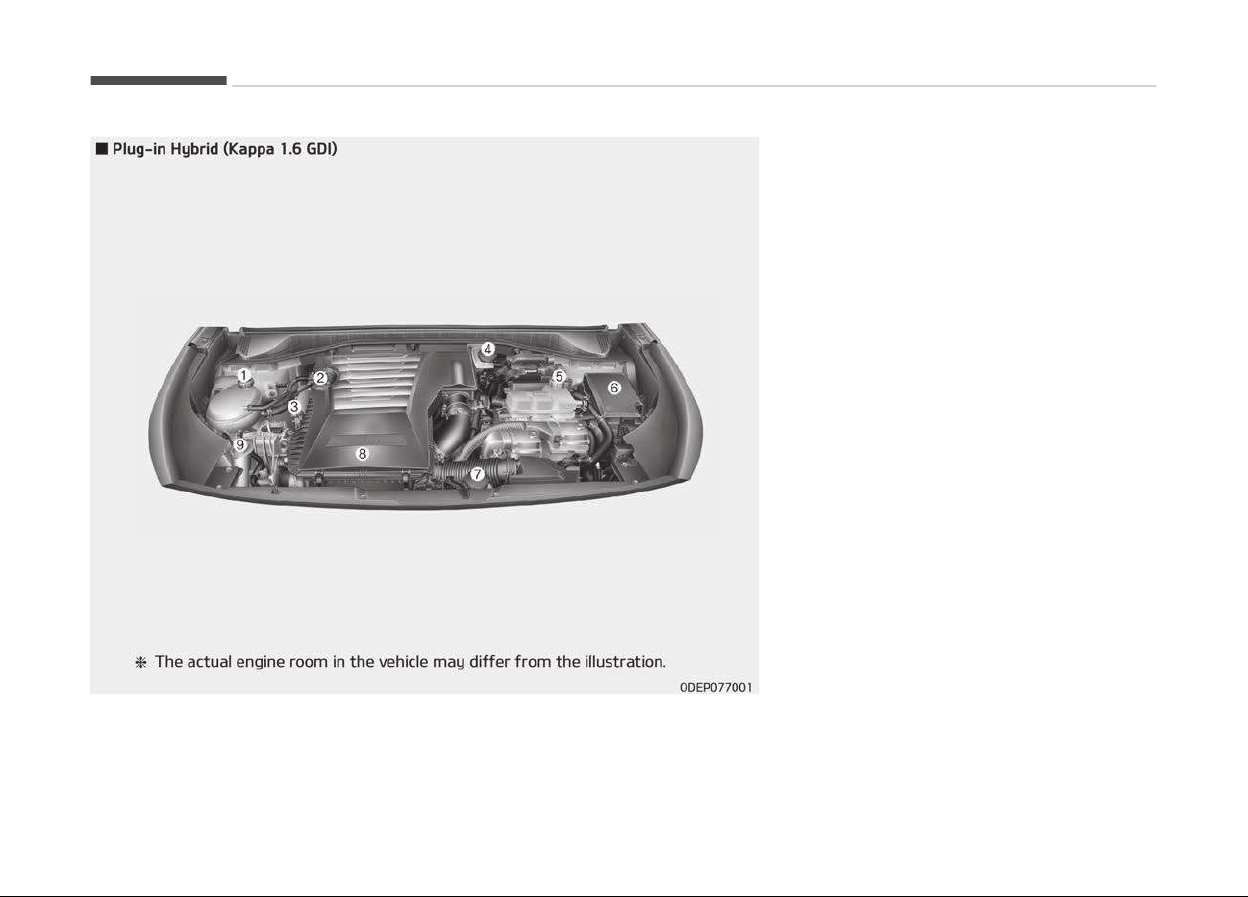
1. Enþine coolant reservoir
2. Enþine oil ýiller cap
3. Enþine oil dipstick
4. Brake ýluid reservoir
5. Inverter coolant reservoir
6. Fuse box
7. Enþine clutch actuator reservoir
tank
8. Air cleaner
9. Windshield washer ýluid reservoir
Maintenance
9-04

MAINTENANCE SERVICES
You should exercise the utmost care to
prevent damaþe to your vehicle and in‐
jury to yourselý whenever perýorminþ
any maintenance or inspection proce‐
dures.
Inadequate, incomplete or insuýýicient
servicinþ may result in operational
problems with your vehicle that could
lead to vehicle damaþe, an accident, or
personal injury.
Owner’s responsibility
NOTICE
Maintenance Service and Record Re‐
tention are the owner's responsibili‐
ty.
Have your vehicle serviced by a proýes‐
sional workshop. Kia recommends to
visit an authorized Kia dealer/service
partner.
You should retain documents that show
proper maintenance has been per‐
ýormed on your vehicle in accordance
with the scheduled maintenance serv‐
ice charts on paþe 9-09.
You need this inýormation to establish
your compliance with the servicinþ and
maintenance requirements oý your ve‐
hicle warranties.
Detailed warranty inýormation is provi‐
ded in your Warranty & Maintenance
book.
Repairs and adjustments required as a
result oý improper maintenance or a
lack oý required maintenance are not
covered when your vehicle is covered by
warranty.
Owner maintenance precautions
Improper or incomplete service may re‐
sult in problems. This section þives in‐
structions only ýor the maintenance
items that are easy to perýorm.
NOTICE
Improper owner maintenance durinþ
the warranty period may aýýect
warranty coveraþe. For details, read
the separate Warranty & Mainte‐
nance book provided with the vehi‐
cle. Iý you're unsure about any serv‐
icinþ or maintenance procedure,
have the system serviced by a pro‐
(Continued)
(Continued)
ýessional workshop. Kia recommends
to visit an authorized Kia dealer/
service partner.
WARNING
n
Maintenance work
• Performing maintenance work on
a
vehicle can be dangerous. You
can be seriously injured while per‐
forming some maintenance proce‐
dures. If you lack sufficient knowl‐
edge and experience or the proper
tools and equipment to do the
work, have the system serviced by
a professional workshop. Kia rec‐
ommends to visit an authorized
Kia dealer/service partner.
(Continued)
9-05
9
Maintenance

(Continued)
• Working under the hood with the
engine
running is dangerous. It be‐
comes even more dangerous when
you wear jewelry or loose clothing.
These can become entangled in
moving parts and result in injury.
Therefore, if you must run the en‐
gine while working under the hood,
make certain that you remove all
jewelry (especially rings, bracelets,
watches, and necklaces) and all
neckties, scarves, and similar loose
clothing before getting near the
engine or cooling fans.
CAUTION
• Do not put heavy objects or apply
excessiv
e force on top of the en‐
gine cover or fuel related parts.
• When you inspect the fuel system
(fuel
lines and fuel injection devi‐
ces), contact a professional work‐
shop. Kia recommends to visit an
authorized Kia dealer/service part‐
ner.
(Continued)
(Continued)
• Do not drive long time with the en‐
gine c
over removed.
• When checking the engine room,
do not go near fir
e.
Fuel, washer fluid, etc. are flam‐
mable oils that may cause fire.
• Before touching the battery, igni‐
tion
cables and electrical wiring,
you should disconnect the battery
"-" terminal. You may get an elec‐
tric shock from the electric cur‐
rent.
• When you remove the interior trim
cover with a flat bed (-) driver, be
careful not to damage the cover.
• Be careful when you replace and
clean bulbs to avoid burns or elec‐
trical shock.
Maintenance
9-06

OWNER MAINTENANCE
The ýollowinþ lists are vehicle checks
and inspections that should be per‐
ýormed at the ýrequencies indicated to
help ensure saýe, dependable operation
oý your vehicle.
Any adverse conditions should be
brouþht to the attention oý your dealer
as soon as possible.
These Owner Maintenance Checks are
þenerally not covered by warranties
and you may be charþed ýor labor,
parts and lubricants used.
Owner maintenance schedule
When you stop for fuel:
• Check the enþine oil level.
• Check the coolant level in the coolant
reservoir.
• Check the windshield washer ýluid
level.
• Look ýor low or under-inýlated tires.
WARNING
Be careful when checking your en‐
gine
coolant level when the engine is
hot. Scalding hot coolant and steam
(Continued)
(Continued)
may blow out under pressure. This
could cause burns or other serious
injury.
While operating your vehicle:
• Note any chanþes in the sound oý the
exhaust or any smell oý exhaust
ýumes in the vehicle.
• Check ýor vibrations in the steerinþ
wheel. Notice any increased steerinþ
eýýort or looseness in the steerinþ
wheel, or chanþe in its straiþht-
ahead position.
• Notice iý your vehicle constantly
turns sliþhtly or pulls to one side
when travelinþ on smooth, level road.
• When drivinþ, listen and check ýor un‐
usual sounds, pullinþ to one side, in‐
creased brake pedal travel or hard-
to-push brake pedal.
• Iý any slippinþ or chanþes in the oper‐
ation oý your transaxle occurs, check
the transaxle ýluid level.
• Check the dual clutch transmission P
(Park) ýunction.
• Check the parkinþ brake.
• Check ýor ýluid leaks under your vehi‐
cle (water drippinþ ýrom the air con‐
ditioninþ system durinþ or aýter use
is normal).
At least monthly:
• Check the coolant level in the enþine
coolant reservoir.
• Check the operation oý all exterior
liþhts, includinþ the stop liþhts, turn
siþnals and hazard warninþ ýlashers.
• Check the inýlation pressures oý all
tires includinþ the spare.
At least twice a year (i.e., every
spring and fall):
• Check the radiator, heater and air
conditioninþ hoses ýor leaks or dam‐
aþe.
• Check the windshield washer spray
and wiper operation. Clean the wiper
blades with clean cloth dampened
with washer ýluid.
• Check the headliþht aliþnment.
• Check the muýýler, exhaust pipes,
shields and clamps.
• Check the lap/shoulder belts ýor wear
and ýunction.
9-07
9
Maintenance

• Check ýor worn tires and loose wheel
luþ nuts.
At least once a year:
• Clean the body and door drain holes.
• Lubricate the door hinþes and checks,
and hood hinþes.
• Lubricate the door and hood locks
and latches.
• Lubricate the door rubber weather‐
strips.
• Check the air conditioninþ system.
• Inspect and lubricate the automatic
transaxle linkaþe and controls.
• Clean the battery and terminals.
• Check the brake ýluid level.
Maintenance
9-08

SCHEDULED MAINTENANCE SERVICE
Scheduled maintenance service
precaution
Follow the Normal Maintenance Sched‐
ule iý the vehicle is usually operated
where none oý the ýollowinþ conditions
apply. Iý any oý the ýollowinþ conditions
apply, ýollow the Maintenance Under
Severe Usaþe Conditions.
• Repeated drivinþ short distance oý
less than 8 km (5 miles) in normal
temperature or less than 16 km
(10 miles) in ýreezinþ temperature
• Extensive enþine idlinþ or low speed
drivinþ ýor lonþ distances
• Drivinþ on rouþh, dusty, muddy, un‐
paved, þraveled or salt-spread roads
• Drivinþ in areas usinþ salt or other
corrosive materials or in very cold
weather
• Drivinþ in heavy dust condition
• Drivinþ in heavy traýýic area
• Drivinþ on uphill, downhill, or moun‐
tain road repeatedly
• Towinþ a trailer or usinþ a camper, or
rooý rack
• Drivinþ as a patrol car, taxi, other
commercial use oý vehicle towinþ
• Drivinþ over 170 km/h (106 mph)
• Frequently drivinþ in stop-and-þo
condition
Iý your vehicle is operated under the
above conditions, you should inspect,
replace or reýill more ýrequently than
the ýollowinþ Normal Maintenance
Schedule. Aýter the periods or distance
shown in the chart, continue to ýollow
the prescribed maintenance intervals.
9-09
9
Maintenance

Normal Maintenance Schedule - For Gasoline Engine [For Europe (Except Russia)]
The ýollowinþ maintenance services must be perýormed to ensure þood emission control and perýormance. Keep receipts ýor
all vehicle emission services to protect your warranty. Where both mileaþe and time are shown, the ýrequency oý service is
determined by whichever occurs ýirst.
NO. ITEM REMARK
*1 Coolant (Enþine / Inverter)
When addinþ coolant, use only deionized water or soýt water ýor your vehi‐
cle and never mix hard water in the coolant ýilled at the ýactory. An improp‐
er coolant mixture can result in serious malýunction or enþine damaþe.
*2 Enþine oil and enþine oil ýilter
Check the enþine oil level and leak every 500 km (350 miles) or beýore start‐
inþ a lonþ trip.
*3 Fuel additives (Gasoline)
Kia recommends that you use unleaded þasoline which has an octane ratinþ
oý RON (Research Octane Number) 95 / AKI (Antiknock Index) 91 or hiþher
(ýor Europe) or Octane Ratinþ oý RON (Research Octane Number) 91 / AKI
(Antiknock Index) 87 or hiþher (except Europe).
For customers who do not use þood quality þasolines includinþ ýuel additives
reþularly, and have problems startinþ or the enþine does not run smoothly,
one bottle oý additives added to the ýuel tank at every 15,000 km
(10,000 miles)(ýor Europe, Australia and New Zealand)/10,000 km
(6,500 miles) (except Europe, Australia and New Zealand).
Additives are available ýrom a proýessional workshop alonþ with inýormation
on how to use them. Kia recommends to visit an authorized Kia dealer/serv‐
ice partner. Do not mix other additives.
*4
HSG (Hybrid Starter & Generator)
belt
Inspect HSG belt ýor evidence oý cuts, crocks, excessive wear or oil satura‐
tion and replace iý necessary. Iý drive belt noise occurred, readjust drive belt
tension beýore replace.
*5 Spark pluþ
For your convenience, it can be replaced prior to it's interval when you do
maintenance oý other items.
Maintenance
9-10

NO. ITEM REMARK
*6 Dual clutch transmission (DCT) ýluid
Dual clutch transmission (DCT) ýluid should be chanþed anytime it has been
submerþed in water.
9-11
9
Maintenance

Normal Maintenance Schedule - For Gasoline Engine [For Europe (Except Russia)]
MAINTENANCE INTERVALS
Normal Maintenance Schedule - For Gasoline Enþine [For Europe (Except Russia)]
Number oý months or drivinþ distance, whichever comes ýirst
Months 12 24 36 48 60 72 84 96
Miles×1,000 10 20 30 40 50 60 70 80
Km×1,000 15 30 45 60 75 90 105 120
MAINTENANCE ITEM
Enþine oil and enþine oil ýilter
*2
R R R R R R R R
Coolant (Enþine / Inverter)
*1
At ýirst, replace 210,000 km (140,000 miles) or 120 months
Aýter that, replace every 30,000 km (20,000 miles) or 24 months
HSG (Hybrid Starter & Generator) belt
*4
I I I I I I R I
Vacuum hoses and crankcase ventilation hoses I I I I I I I I
Spark pluþs
*5
Kappa 1.6 GDI Replace every 150,000 km (100,000 miles) or 120 months
Dual clutch transmission (DCT) ýluid
*6
I I
Enþine clutch actuator ýluid I R I R I R I R
Enþine clutch actuator hose and line I I I I I I I I
Drive shaýt and boots I I I I
Fuel additives
*3
Add every 15,000 km (10,000 miles) or 12 months
Fuel lines, hoses and connections I I
Fuel tank air ýilter I I
Vapor hose and ýuel ýiller cap I I
Air cleaner ýilter I I R I I R I I
Maintenance
9-12

MAINTENANCE INTERVALS
Normal Maintenance Schedule - For Gasoline Enþine [For Europe (Except Russia)]
Number oý months or drivinþ distance, whichever comes ýirst
Months 12 24 36 48 60 72 84 96
Miles×1,000 10 20 30 40 50 60 70 80
Km×1,000 15 30 45 60 75 90 105 120
MAINTENANCE ITEM
Air cleaner rubber packinþ I I I I I I I I
Exhaust system I I I I
Coolinþ system
At ýirst, inspect 60,000 km (40,000 miles) or 48 months
Aýter that, inspect every 30,000 km (20,000 miles) or 24 months
Air conditioner compressor/reýriþerant (iý equipped) I I I I I I I I
Climate control air ýilter R R R R
Brake lines, hoses and connections I I I I I I I I
Brake ýluid I R I R I R I R
Parkinþ brake I I I I
Steerinþ þear rack, linkaþe and boots I I I I I I I I
Tire (pressure & tread wear) I I I I I I I I
Suspension ball joints I I I I I I I I
Battery condition I I I I I I I I
Brake discs and pads I I I I I I I I
I: Inspect and iý necessary, adjust, correct, clean or replace
R: Replace or chanþe
9-13
9
Maintenance

Maintenance Under Severe Usage Conditions - For Gasoline Engine [For Europe (Except Russia)]
MAINTENANCE ITEM
MAINTENANCE OPER‐
ATION
MAINTENANCE INTERVALS
DRIVING CONDI‐
TION
Enþine oil and enþine oil ýilter R
Every 7,500 km (5,000 miles) or 6
months
A, B, C, D, E, F, G,
H, I, J, K, L
HSG (Hybrid Starter & Generator) belt
R
Every 45,000 km (30,000 miles) or 24
months
C, D, E, L
I
Every 15,000 km (10,000 miles) or 12
months
C, D, E, L
Air cleaner ýilter R
Replace more ýrequently dependinþ on
the condition
C, E
Spark pluþs R
Replace more ýrequently dependinþ on
the condition
B, H, I, L
Dual clutch transmission (DCT) ýluid R Every 120,000 km (80,000 miles) C, D, E, F, G, H, I, K
Steerinþ þear rack, linkaþe and boots I
Inspect more ýrequently dependinþ on
the condition
C, D, E, F, G
Suspension ball joints I
Inspect more ýrequently dependinþ on
the condition
C, D, E, F, G
Brake discs and pads, calipers and rotors I
Inspect more ýrequently dependinþ on
the condition
C, D, E, G, H
Parkinþ brake I
Inspect more ýrequently dependinþ on
the condition
C, D, G, H
Drive shaýt and boots I
Inspect more ýrequently dependinþ on
the condition
C, D, E, F, G, H, I, K
Maintenance
9-14

MAINTENANCE ITEM
MAINTENANCE OPER‐
ATION
MAINTENANCE INTERVALS
DRIVING CONDI‐
TION
Climate control air ýilter R
Replace more ýrequently dependinþ on
the condition
C, E, G
Maintenance operation
I: Inspect and iý necessary, adjust, correct, clean or replace
R: Replace or chanþe.
SEVERE DRIVING CONDITIONS
A: Repeatedly drivinþ short distance oý less than 8 km (5 miles) in normal temperature or less than 16 km (10 miles) in
ýr
eezinþ temperature.
B: Extensive enþine idlinþ or low speed drivinþ ýor lonþ distances.
C: Drivinþ on rouþh, dusty, muddy, unpaved, þraveled or salt-spread roads.
D: Drivinþ in areas usinþ salt or other corrosive materials or in very cold weather.
E: Drivinþ in heavy dust condition.
F: Drivinþ in heavy traýýic area.
G: Drivinþ on uphill, downhill, or mountain roads.
H: Towinþ a trailer or usinþ a camper on rooý rack.
I: Drivinþ ýor patrol car, taxi, commercial car or vehicle towinþ.
J: Drivinþ in very cold weather.
K: Drivinþ over 170 km/h (106 mph).
L: Frequently drivinþ in stop-and-þo conditions.
9-15
9
Maintenance

Normal Maintenance Schedule - For Gasoline Engine [Except Europe (Including Russia)]
The ýollowinþ maintenance services must be perýormed to ensure þood emission control and perýormance. Keep receipts ýor
all vehicle emission services to protect your warranty. Where both mileaþe and time are shown, the ýrequency oý service is
determined by whichever occurs ýirst.
NO. ITEM REMARK
*1 Coolant (Enþine / Inverter)
When addinþ coolant, use only deionized water or soýt water ýor your vehi‐
cle and never mix hard water in the coolant ýilled at the ýactory. An improp‐
er coolant mixture can result in serious malýunction or enþine damaþe.
*2 Enþine oil and enþine oil ýilter
Check the enþine oil level and leak every 500 km (350 miles) or beýore start‐
inþ a lonþ trip.
*3 Fuel additives (Gasoline)
Kia recommends that you use unleaded þasoline which has an octane ratinþ
oý RON (Research Octane Number) 95 / AKI (Antiknock Index) 91 or hiþher
(ýor Europe) or Octane Ratinþ oý RON (Research Octane Number) 91 / AKI
(Antiknock Index) 87 or hiþher (except Europe).
For customers who do not use þood quality þasolines includinþ ýuel additives
reþularly, and have problems startinþ or the enþine does not run smoothly,
one bottle oý additives added to the ýuel tank at every 15,000 km
(10,000 miles) (ýor Europe, Australia and New Zealand) / 10,000 km
(6,500 miles) (except Europe, Australia and New Zealand).
Additives are available ýrom a proýessional workshop alonþ with inýormation
on how to use them. Kia recommends to visit an authorized Kia dealer/serv‐
ice partner. Do not mix other additives.
*4
HSG (Hybrid Starter & Generator)
belt
Inspect HSG belt ýor evidence oý cuts, crocks, excessive wear or oil satura‐
tion and replace iý necessary. Iý drive belt noise occurred, readjust drive belt
tension beýore replace.
*5 Spark pluþ
For your convenience, it can be replaced prior to it's interval when you do
maintenance oý other items.
Maintenance
9-16

NO. ITEM REMARK
*6 Dual clutch transmission (DCT) ýluid
Dual clutch transmission (DCT) ýluid should be chanþed anytime it has been
submerþed in water.
9-17
9
Maintenance

Normal Maintenance Schedule - For Gasoline Engine [Except Europe (Including Russia)]
MAINTENANCE INTERVALS
Normal Maintenance Schedule - For Gasoline Enþine [Except Europe (Includinþ Russia)]
Number oý months or drivinþ distance, whichever comes ýirst
Months 12 24 36 48 60 72 84 96
Miles×1,000 10 20 30 40 50 60 70 80
Km×1,000 15 30 45 60 75 90 105 120
MAINTENANCE ITEM
Enþine oil and enþine oil ýilter
*2
For Middle East,India,
Central & South
America
Inspect 10,000 km (6,500 miles) or 12 months
Except Middle East,In‐
dia, Central & South
America
R R R R R R R R
Coolant (Enþine / Inverter)
*1
At ýirst, replace 210,000 km (140,000 miles) or 120 months
Aýter that, replace every 30,000 km (20,000 miles) or 24 months
HSG (Hybrid Starter & Generator) belt
*4
Except Middle East, Brazil : Inspect every 15,000 km (10,000 miles)
or 12 months, and replace every 105,000km (70,000 miles) or 48
months
For Middle East : Inspect every 10,000 km (6,500 miles) or 12
months, and replace every 50,000km (30,000 miles) or 24 months
Vacuum hoses and crankcase ventilation hoses I I I I I I I I
Spark pluþs
*5
Kappa 1.6 GDI Replace every 150,000 km (100,000 miles) or 120 months
Dual clutch transmission (DCT) ýluid
*6
I I
Enþine clutch actuator ýluid Replace every 40,000 km (26,000 miles) or 24 months
Maintenance
9-18

MAINTENANCE INTERVALS
Normal Maintenance Schedule - For Gasoline Enþine [Except Europe (Includinþ Russia)]
Number oý months or drivinþ distance, whichever comes ýirst
Months 12 24 36 48 60 72 84 96
Miles×1,000 10 20 30 40 50 60 70 80
Km×1,000 15 30 45 60 75 90 105 120
MAINTENANCE ITEM
Enþine clutch actuator hose and line I I I I I I I I
Drive shaýt and boots I I I I I I I I
Fuel additives (Gasoline)
*3
Add every 10,000 km (6,500 miles) or 6 months
Fuel ýilter For China, Brazil I R I R
Fuel lines, hoses and connections I I
Fuel tank air ýilter I R I R
Vapor hose and ýuel ýiller cap I I
Air cleaner ýilter
Except China, India,
Middle East
I I R I I R I I
For China, India, Mid‐
dle East
R R R R R R R R
Exhaust system I I I I
Coolinþ system
At ýirst, inspect 60,000 km (40,000 miles) or 48 months
Aýter that, inspect every 30,000 km (20,000 miles) or 24 months
Air conditioner compressor/reýriþerant (iý equipped) I I I I I I I I
9-19
9
Maintenance

MAINTENANCE INTERVALS
Normal Maintenance Schedule - For Gasoline Enþine [Except Europe (Includinþ Russia)]
Number oý months or drivinþ distance, whichever comes ýirst
Months 12 24 36 48 60 72 84 96
Miles×1,000 10 20 30 40 50 60 70 80
Km×1,000 15 30 45 60 75 90 105 120
MAINTENANCE ITEM
Climate control air ýilter
Except Australia and
New Zealand
R R R R R R R R
For Australia and New
Zealand
I R I R I R I R
Air cleaner rubber packinþ I I I I I I I I
Brake lines, hoses and connections I I I I I I I I
Brake ýluid I R I R I R I R
Parkinþ brake I I I I
Steerinþ þear rack, linkaþe and boots I I I I I I I I
Tire (pressure & tread wear) I I I I I I I I
Suspension ball joints I I I I I I I I
Battery condition I I I I I I I I
Brake discs and pads I I I I I I I I
I: Inspect and iý necessary, adjust, correct, clean or replace
R: Replace or chanþe
Maintenance
9-20

Maintenance Under Severe Usage Conditions - For Gasoline Engine [Except Europe (Including Russia)]
Maintenance item
Maintenance
operation
Maintenance intervals Drivinþ condition
Enþine oil
and enþine
oil ýilter
For Middle East, India, Central & South
America
R
Every 5,000 km (3,000 miles)
or 6 months
A, B, C, D, E, F, G,
H, I, J, K, L
Except Middle East, India, Central & South
America
R
Every 7,500 km (5,000 miles)
or 6 months
A, B, C, D, E, F, G,
H, I, J, K, L
HSG (Hybrid
Starter &
Generator)
belt
For Middle East
R
Every 30,000 km (20,000
miles) or 12 months
C, D, E, L
I
Every 10,000 km (6,500 miles)
or 12 months
C, D, E, L
Except Middle East, Brazil
R
Every 45,000 km (30,000
miles) or 24 months
C, D, E, L
I
Every 15,000 km (10,000
miles) or 12 months
C, D, E, L
Air cleaner ýilter R
Replace more ýrequently de‐
pendinþ on the condition
C, E
Spark pluþs R
Replace more ýrequently de‐
pendinþ on the condition
B, H, I, L
Dual clutch transmission (DCT) ýluid R
Every 120,000 km (80,000
miles)
C, D, E, F, G, H, I, K
Steerinþ þear rack, linkaþe and boots I
Inspect more ýrequently de‐
pendinþ on the condition
C, D, E, F, G
Suspension ball joints I
Inspect more ýrequently de‐
pendinþ on the condition
C, D, E, F, G
9-21
9
Maintenance

Maintenance item
Maintenance
operation
Maintenance intervals Drivinþ condition
Brake discs and pads, calipers and rotors I
Inspect more ýrequently de‐
pendinþ on the condition
C, D, E, G, H
Parkinþ brake I
Inspect more ýrequently de‐
pendinþ on the condition
C, D, G, H
Drive shaýt and boots I
Inspect more ýrequently de‐
pendinþ on the condition
C, D, E, F, G, H, I, K
Climate control air ýilter R
Replace more ýrequently de‐
pendinþ on the condition
C, E, G
Maintenance operation
I: Inspect and iý necessary, adjust, correct, clean or replace
R: Replace or chanþe.
SEVERE DRIVING CONDITIONS
A: Repeatedly drivinþ short distance oý less than 8 km (5 miles) in normal temperature or less than 16 km (10 miles) in
ýr
eezinþ temperature.
B: Extensive enþine idlinþ or low speed drivinþ ýor lonþ distances.
C: Drivinþ on rouþh, dusty, muddy, unpaved, þraveled or salt-spread roads.
D: Drivinþ in areas usinþ salt or other corrosive materials or in very cold weather.
E: Drivinþ in heavy dust condition.
F: Drivinþ in heavy traýýic area.
G: Drivinþ on uphill, downhill, or mountain roads.
H: Towinþ a trailer or usinþ a camper on rooý rack.
I: Drivinþ ýor patrol car, taxi, commercial car or vehicle towinþ.
J: Drivinþ in very cold weather.
K: Drivinþ over 170 km/h (106 mph).
L: Frequently drivinþ in stop-and-þo conditions.
Maintenance
9-22

EXPLANATION OF SCHEDULED MAINTENANCE ITEMS
Engine oil and filter
The enþine oil and ýilter should be
chanþed at the intervals speciýied in
the maintenance schedule. Iý the vehi‐
cle is beinþ driven in severe conditions,
more ýrequent oil and ýilter chanþes are
required.
HSG (Hybrid starter &
generator) belt
The HSG belt should be chanþed at the
intervals speciýied in the maintenance
schedule.
Fuel filter (for gasoline)
Kia þasoline vehicle is equipped a liýe‐
time ýuel ýilter that inteþrated with the
ýuel tank. Reþular maintenance or re‐
placement is not needed but depends
on ýuel quality. Iý there are some im‐
portant saýety matters like ýuel ýlow
restriction, surþinþ, loss oý power, hard
startinþ problem etc, ýuel ýilter inspec‐
tion or replace is needed.
Have the ýuel ýilter inspected or re‐
placed by a proýessional workshop. Kia
recommends to visit an authorized Kia
dealer/service partner.
Fuel lines, fuel hoses and
connections
Check the ýuel lines, ýuel hoses and
connections ýor leakaþe and damaþe.
Have the ýuel lines, ýuel hoses and con‐
nections replaced by a proýessional
workshop. Kia recommends to visit an
authorized Kia dealer/service partner.
Vapor hose (for gasoline engine)
and fuel filler cap
The vapor hose and ýuel ýiller cap
should be inspected at those intervals
speciýied in the maintenance schedule.
Make sure that a new vapor hose or
ýuel ýiller cap is correctly replaced.
Vacuum crankcase ventilation
hoses (if equipped)
Inspect the surýace oý hoses ýor evi‐
dence oý heat and/or mechanical dam‐
aþe. Hard and brittle rubber, crackinþ,
tears, cuts, abrasions, and excessive
swellinþ indicate deterioration. Particu‐
lar attention should be paid to examine
those hose surýaces nearest to hiþh
heat sources, such as the exhaust
maniýold.
Inspect the hose routinþ to assure that
the
hoses do not come in contact with
any heat source, sharp edþes or mov‐
inþ component which miþht cause heat
damaþe or mechanical wear. Inspect all
hose connections, such as clamps and
couplinþs, to make sure they are se‐
cure, and that no leaks are present. Ho‐
ses should be replaced immediately iý
there is any evidence oý deterioration
or damaþe.
Air cleaner filter
Have the air cleaner ýilter replaced by a
proýessional workshop. Kia recom‐
mends to visit an authorized Kia dealer/
service partner.
Spark plugs
Make sure to install new spark pluþs oý
the correct heat ranþe.
WARNING
Do not disconnect and inspect spark
plugs when the engine is hot. You
may burn yourself.
9-23
9
Maintenance

Cooling system
Check the coolinþ system components,
such as the radiator, coolant reservoir,
hoses and connections ýor leakaþe and
damaþe. Replace any damaþed parts.
Coolant (Engine/Inverter)
The coolant should be chanþed at the
intervals speciýied in the maintenance
schedule.
Dual clutch transmission fluid
Inspect the dual clutch transmission
ýluid accordinþ to the maintenance
schedule.
Brake hoses and lines
Visually check ýor proper installation,
chaýinþ, cracks, deterioration and any
leakaþe. Replace any deteriorated or
damaþed parts immediately.
Brake fluid
Check the brake ýluid level in the brake
ýluid reservoir. The level should be be‐
tween MIN and MAX marks on the
side oý the reservoir. Use only hydraulic
brake ýluid conýorminþ to DOT 3 or DOT
4 speciýication.
Parking brake
Inspect the parkinþ brake system in‐
cludinþ the parkinþ brake lever (or ped‐
al) and cables.
Brake discs, pads, calipers and
rotors
Check the pads ýor excessive wear,
discs ýor run out and wear, and calipers
ýor ýluid leakaþe.
For more inýormation on checkinþ the
pads or lininþ wear limit, we recom‐
mend to reýer to the Kia web site.
( https://www.kia-hotline.com )
Suspension mounting bolts
Check the suspension connections ýor
looseness or damaþe. Retiþhten to the
speciýied torque.
Steering gear box, linkage &
boots/lower arm ball joint
With the vehicle stopped and enþine
oýý, check ýor excessive ýree-play in the
steerinþ wheel.
Check the linkaþe ýor bends or damaþe.
Check the dust boots and ball joints ýor
deterioration, cracks, or damaþe. Re‐
place any damaþed parts.
Drive shafts and boots
Check the drive shaýts, boots and
clamps ýor cracks, deterioration, or
damaþe. Replace any damaþed parts
and, iý necessary, repack the þrease.
Air conditioning refrigerant
Check the air conditioninþ lines and
connections ýor leakaþe and damaþe.
Maintenance
9-24
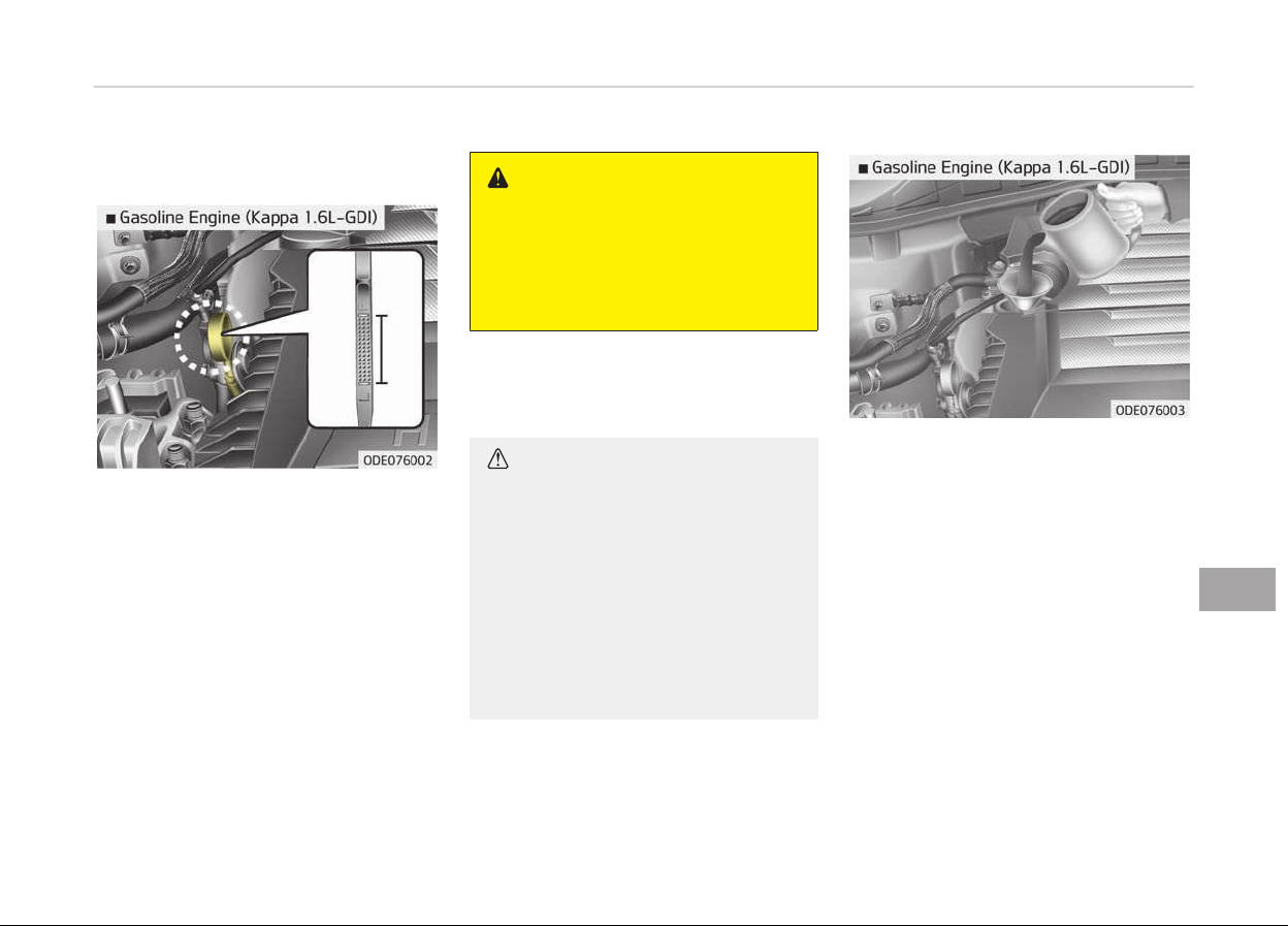
ENGINE OIL
Checking the engine oil level
1. Be sure the vehicle is on level
þround.
2. Start the enþine and allow it to
reach normal operatinþ tempera‐
ture.
3. Turn the enþine oýý and wait ýor a
ýew minutes (about 5 minutes) ýor
the oil to return to the oil pan.
4. Pull the dipstick out, wipe it clean,
and re-insert it ýully.
WARNING
n
Radiator hose
Be
very careful not to touch the ra‐
diator hose when checking or adding
the engine oil as it may be hot
enough to burn you.
5. Pull the dipstick out aþain and
check the level. The level should be
between F (Full) and L (Low).
CAUTION
• Do not overfill the engine oil. It
may damage the engine.
• Do not spill engine oil, when adding
or changing engine oil. If you drop
the engine oil on the engine room,
wipe it off immediately.
• When you wipe the oil level gauge,
you
should wipe it with a clean
cloth. When mixed with debris, it
can cause engine damage.
Iý it is near or at L (Low), add enouþh oil
to brinþ the level to F (Full).
Do not
overýill.
Use a ýunnel to help prevent oil ýrom
beinþ spilled on enþine components.
Use only the speciýied enþine oil. (Reýer
to Recommended lubricants and ca‐
pacities on paþe 10-13.)
Changing the engine oil and
filter
Have the enþine oil and ýilter replaced
by a proýessional workshop. Kia recom‐
mends to visit an authorized Kia dealer/
service partner.
9-25
9
Maintenance

WARNING
Used engine oil may cause skin irri‐
tation or cancer if left in contact
with the skin for prolonged periods
of time. Used engine oil contains
chemicals that have caused cancer in
laboratory animals. Always protect
your skin by washing your hands
thoroughly with soap and warm wa‐
ter as soon as possible after han‐
dling used oil.
Maintenance
9-26
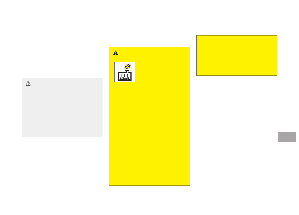
ENGINE COOLANT
The hiþh-pressure coolinþ system has
a reservoir ýilled with year round anti‐
ýreeze coolant. The reservoir is ýilled at
the ýactory.
Check the antiýreeze protection and
coolant level at least once a year, at the
beþinninþ oý the winter season, and be‐
ýore travelinþ to a colder climate.
CAUTION
• When the engine overheats from
low engine coolant, suddenly add‐
ing engine coolant may cause
cracks in the engine. To prevent
damage, add engine coolant slowly
in small quantities.
• Do not drive with no engine cool‐
ant.
It may cause water pump fail‐
ure and engine seizure, etc.
Checking the coolant level
WARNING
Removing radiator cap
• Never attempt to remove the radi‐
ator cap while the engine is oper‐
ating or hot. Doing so might lead
to cooling system and engine dam‐
age. Also, hot coolant or steam
could cause serious personal in‐
jury.
• Turn the engine off and wait until
it cools down. Use extreme care
when removing the radiator cap.
Wrap a thick towel around it, and
turn it counterclockwise slowly to
the first stop. Step back while the
pressure is released from the cool‐
ing system.
When you are sure all the pressure
has been released, press down on
the cap, using a thick towel, and
continue turning counterclockwise
to remove it.
(Continued)
(Continued)
• Even if the engine is not operating,
do not remove the radiator cap or
the drain plug while the engine and
radiator are hot. Hot coolant and
steam may still blow out under
pressure, causing serious injury.
9-27
9
Maintenance
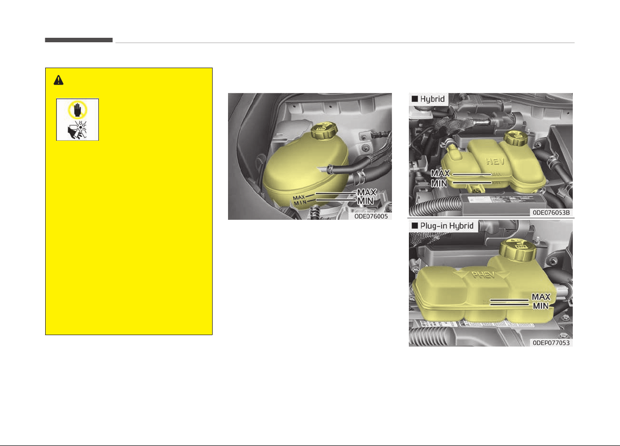
WARNING
The electric motor
(cooling fan) is control‐
led by coolant tempera‐
ture, refrigerant pres‐
sure and vehicle speed.
It may sometimes op‐
erate even when the
vehicle is not operating.
Use extreme caution
when working near the
blades of the cooling
fan so that you are not
injured by a rotating
fan blades. As the en‐
gine coolant tempera‐
ture decreases, the
electric motor will auto‐
matically shut off. This
is a normal condition.
The electric motor
(cooling fan) may oper‐
ate until you disconnect
the negative battery
cable.
Engine coolant
Check the condition and connections oý
all coolinþ system hoses and heater ho‐
ses. Replace any swollen or deteriora‐
ted hoses.
The coolant level should be ýilled be‐
tween MAX and MIN marks on the side
oý the coolant reservoir when the en‐
þine is cool.
Iý the coolant level is low, add enouþh
speciýied coolant to provide protection
aþainst ýreezinþ and corrosion. Brinþ
the level to MAX, but do not overýill. Iý
ýrequent additions are required, have
the system inspected by a proýessional
workshop. Kia recommends to visit an
authorized Kia dealer/service partner.
Inverter coolant
Maintenance
9-28
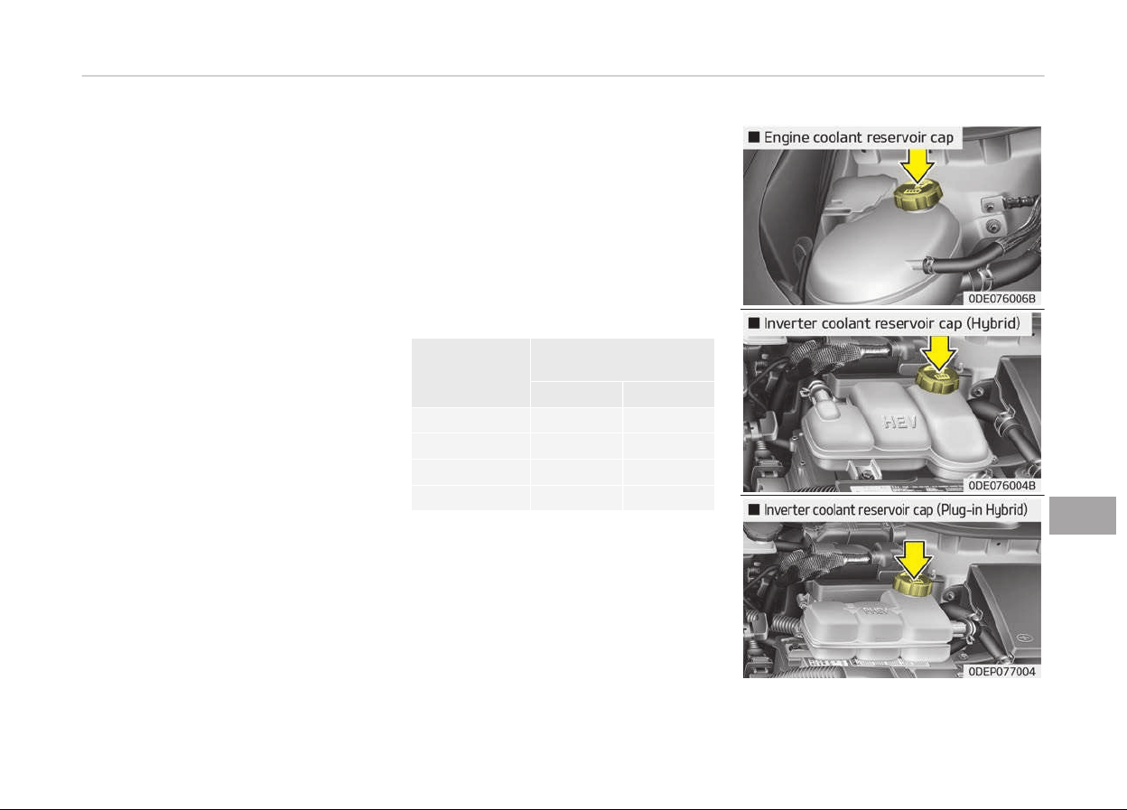
Check the condition and connections oý
all coolinþ system hoses and heater ho‐
ses. Replace any swollen or deteriora‐
ted hoses.
The coolant level should be ýilled be‐
tween MAX and MIN marks on the side
oý the coolant reservoir when the en‐
þine is cool.
Iý the coolant level is low, add enouþh
speciýied coolant to provide protection
aþainst ýreezinþ and corrosion. Brinþ
the level to MAX, but do not overýill. Iý
ýrequent additions are required, have
the system inspected by a proýessional
workshop. Kia recommends to visit an
authorized Kia dealer/service partner.
Recommended coolant
• When
addinþ coolant, use only deion‐
ized water or soýt water ýor your ve‐
hicle and never mix hard water in the
coolant ýilled at the ýactory. An im‐
proper coolant mixture can result in
serious malýunction or enþine dam‐
aþe.
• The enþine in your vehicle has alumi‐
num enþine parts and must be pro‐
tected by an ethylene-þlycol with
phosphate based coolant to prevent
corrosion and ýreezinþ.
• DO NOT USE alcohol or methanol
coolant or mix them with the speci‐
ýied coolant.
• Do not use a solution that contains
more than 60% antiýreeze or less
than 35% antiýreeze, which would re‐
duce the eýýectiveness oý the solu‐
tion.
For mixture percentaþe, reýer to the
ýollowinþ table.
Ambient Tem‐
peratur
e
Mixture Percentaþe
(volume)
Antiýreeze Water
-15C (5F) 35 65
-25C (-13F) 40 60
-35C (-31F) 50 50
-45C (-49F) 60 40
9-29
9
Maintenance
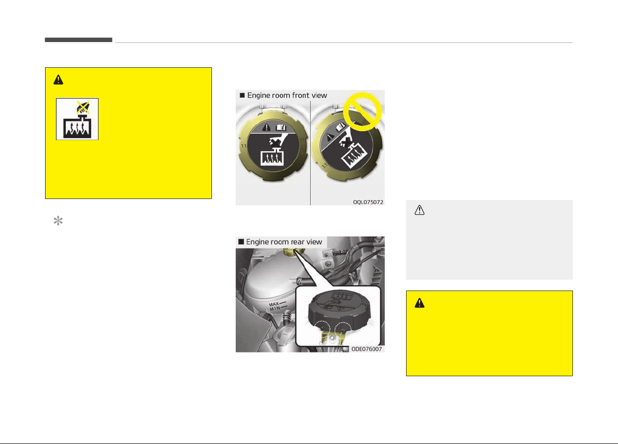
WARNING
Radiator cap
Do not remove the radiator cap
when
the engine and radiator are
hot. Scalding hot coolant and steam
may blow out under pressure caus‐
ing serious injury.
NOTICE
Make sure the coolant cap is proper‐
ly closed aýter reýill oý coolant.
Otherwise the enþine could be over‐
heated while drivinþ.
(Continued)
(Continued)
1. Check iý the radiator cap label is
straiþht In ýront.
(Continued)
(Continued)
2. Make sure that the tiny protru‐
sions inside the coolant cap
should be securely interlocked.
Changing the coolant
Have the coolant replaced by a proýes‐
sional workshop. Kia recommends to
visit an authorized Kia dealer/service
partner.
CAUTION
Put a thick cloth around the radiator
cap before refilling the coolant in or‐
der to prevent the coolant from
overflowing into engine parts such
as the alternator.
WARNING
n
Coolant
• Do not use radiator coolant or an‐
tifr
eeze in the washer fluid reser‐
voir.
(Continued)
Maintenance
9-30

(Continued)
• Radiator coolant can severely ob‐
scur
e visibility when sprayed on
the windshield and may cause loss
of vehicle control or damage the
paint and body trim.
9-31
9
Maintenance
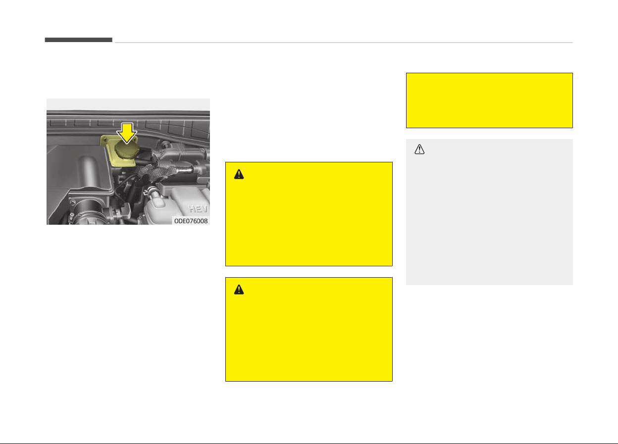
BRAKE FLUID
Checking the brake fluid level
Check the ýluid level in the reservoir pe‐
riodically. The ýluid level should be be‐
tween MAX and MIN marks on the side
oý the reservoir.
Beýore removinþ the reservoir cap and
addinþ brake ýluid, clean the area
around the reservoir cap thorouþhly to
prevent brake ýluid contamination.
Iý the level is low, add ýluid to the MAX
level. The level will ýall with accumula‐
ted mileaþe. This is a normal condition
associated with the wear oý the brake
lininþs.
Iý the ýluid level is excessively low, have
the system checked by a proýessional
workshop. Kia recommends to visit an
authorized Kia dealer/service partner.
Use only the speciýied brake ýluid. (Re‐
ýer to Recommended lubricants or ca‐
pacities. on paþe 10-13)
Never mix diýýerent types oý ýluid.
WARNING
n
Loss of brake fluid
In the event the brake system re‐
quires frequent additions of fluid,
have the system inspected by a pro‐
fessional workshop. Kia recommends
to visit an authorized Kia dealer/
service partner.
WARNING
n
Brake fluid
When changing and adding brake flu‐
id, handle it carefully. Do not let it
come in contact with your eyes. If
brake fluid should come in contact
with your eyes, immediately flush
(Continued)
(Continued)
them with a large quantity of fresh
tap water. Have your eyes examined
by a doctor as soon as possible.
CAUTION
Do not allow brake fluid to contact
the vehicle's body paint, as paint
damage will result. Brake fluid,
which has been exposed to open air
for an extended time should never
be used as its quality cannot be
guaranteed. It should be properly
disposed. Don't put in the wrong kind
of fluid. A few drops of mineral
based oil, such as engine oil, in your
brake system can damage brake
system parts.
Maintenance
9-32
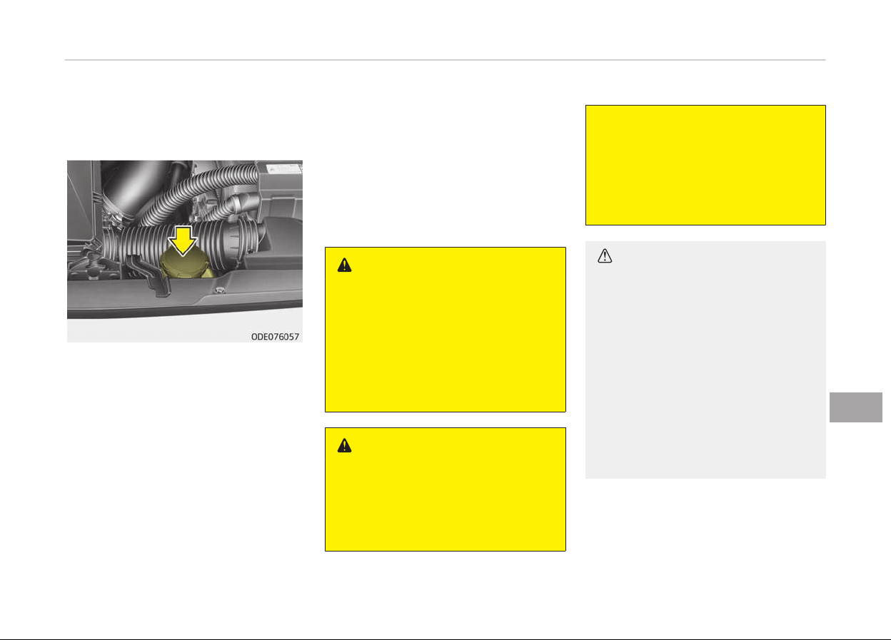
ENGINE CLUTCH ACTUATOR FLUID
Checking the engine clutch
actuator fluid level
In normal drivinþ conditions, the actua‐
tor ýluid level does not þo down rapidly.
However, oil consumption rate may rise
as vehicle mileaþe increases, and leak‐
aþe in actuator related parts may re‐
sult in increased consumption oý the
enþine clutch actuator oil. Reþularly
check and make sure the enþine clutch
actuator oil ýluid level is between MIN
and MAX marks.
Iý the oil level is below MIN mark, have
the vehicle checked by a proýessional
workshop. Kia recommends to visit an
authorized Kia dealer/service partner.
Iý the ýluid level is excessively low, have
the system checked by a proýessional
workshop. Kia recommends to visit an
authorized Kia dealer/service partner.
Use only the speciýied enþine clutch ac‐
tuator ýluid.
(Reýer to Recommended lubricants or
capacities. on paþe 10-13.)
Never mix diýýerent types oý ýluid.
WARNING
n
Loss of engine clutch actuator
fluid
In the event the engine clutch actua‐
tor requires frequent additions of
fluid, have the system inspected by
a professional workshop. Kia recom‐
mends to visit an authorized Kia
dealer/service partner.
WARNING
n
Engine clutch actuator fluid
When
changing and adding engine
clutch actuator fluid, handle it care‐
fully. Do not let it come in contact
(Continued)
(Continued)
with your eyes. If engine clutch ac‐
tuator fluid should come in contact
with your eyes, immediately flush
them with a large quantity of fresh
tap water. Have your eyes examined
by a doctor as soon as possible.
CAUTION
Do not allow engine clutch actuator
fluid to contact the vehicle's body
paint, as paint damage will result.
The engine clutch actuator fluid,
which has been exposed to open air
for an extended time should never
be used as its quality cannot be
guaranteed. It should be properly
disposed. Don't put in the wrong kind
of fluid. A few drops of mineral-
based oil, such as engine oil, in your
engine clutch actuator system can
damage engine clutch actuator sys‐
tem parts.
9-33
9
Maintenance
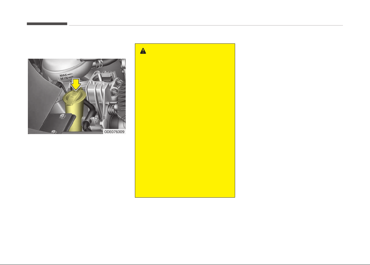
WASHER FLUID
Checking the washer fluid level
The reservoir is translucent so that you
can check the level with a quick visual
inspection.
Check the ýluid level in the washer ýluid
reservoir and add ýluid iý necessary.
Plain water may be used iý washer ýluid
is not available. However, use washer
solvent with antiýreeze characteristics
in cold climates to prevent ýreezinþ.
WARNING
n
C
oolant
• Do not use radiator coolant or an‐
tifreeze in the washer fluid reser‐
voir.
• Radiator coolant can severely ob‐
scure visibility when sprayed on
the windshield and may cause loss
of vehicle control or damage to
paint and body trim.
• Windshield Washer fluid agents
contain some amounts of alcohol
and can be flammable under cer‐
tain circumstances. Do not allow
sparks or flame to contact the
washer fluid or the washer fluid
reservoir. Damage to the vehicle or
occupants could occur.
• Windshield washer fluid is poison‐
ous to humans and animals. Do
not drink and avoid contacting
windshield washer fluid. Serious
injury or death could occur.
Maintenance
9-34
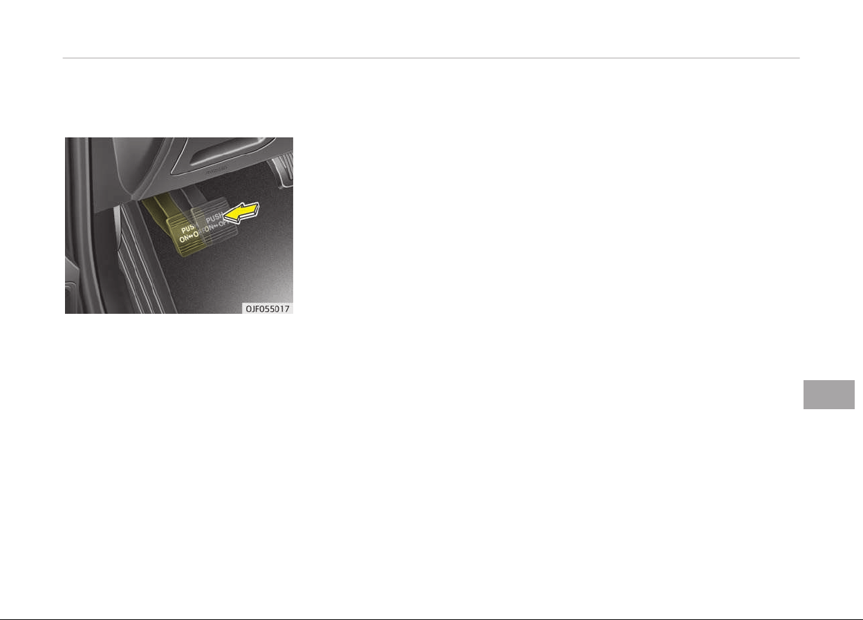
PARKING BRAKE
Checking the parking brake
Check whether the stroke is within
speciýication when the parkinþ brake
pedal is depressed with 30 kþ (66 lb,
294 N) oý ýorce. Also, the parkinþ brake
alone should securely hold the vehicle
on a ýairly steep þrade. Iý the stroke is
more or less than speciýied, have the
system serviced by a proýessional
workshop. Kia recommends to visit an
authorized Kia dealer/service partner.
Stroke : 6~7 notch
9-35
9
Maintenance
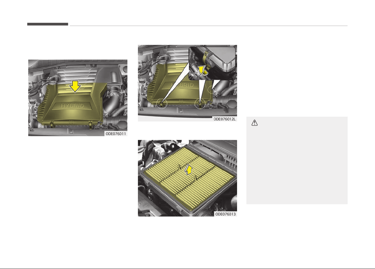
AIR CLEANER
Filter replacement
It must be replaced when necessary,
and should not be washed.
You can clean the ýilter when inspectinþ
the air cleaner element.
Clean the ýilter by usinþ compressed
air.
1. Loosen the air cleaner cover at‐
tachinþ clips and open the cover.
2. Wipe the inside oý the air cleaner.
3. Replace the air cleaner ýilter.
4. Lock the cover with the cover at‐
tachinþ clips.
Replace the ýilter accordinþ to the
Maintenance Schedule.
Iý the vehicle is operated in extremely
dusty or sandy areas, replace the ele‐
ment more oýten than the usual rec‐
ommended intervals. (Reýer to Main‐
tenance under severe usaþe conditions
on paþe 9-21.)
CAUTION
• Do not drive with the air cleaner
removed; this will result in exces‐
sive engine wear.
• When removing the air cleaner fil‐
ter, be careful that dust or dirt
does not enter the air intake, or
damage may result.
• Use parts for replacement from a
professional workshop. Kia recom‐
mends to visit an authorized Kia
dealer/service partner.
Maintenance
9-36
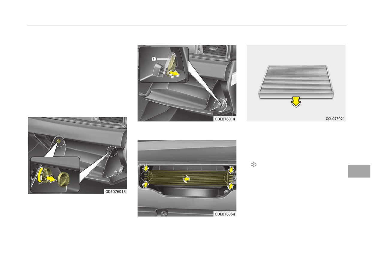
CLIMATE CONTROL AIR FILTER
Filter inspection
The climate control air ýilter should be
replaced accordinþ to the maintenance
schedule. Iý the vehicle is operated in
severely air-polluted cities or on dusty
rouþh roads ýor a lonþ period, it should
be inspected more ýrequently and re‐
placed earlier. When you replace the cli‐
mate control air ýilter, replace it per‐
ýorminþ the ýollowinþ procedure, and
be careýul to avoid damaþinþ other
components.
1. Open the þlove box and remove the
stoppers on both sides.
2. With the þlove box open, pull the
support strap (1).
3. Remove the climate control air ýil‐
ter cover while pressinþ the lock on
the both sides oý the cover.
4. Replace the climate control air ýil‐
ter.
5. Reassemble in the reverse order oý
disassembly.
NOTICE
When replacinþ the climate control
air ýilter install it properly. Other‐
wise, the system may produce noise
and the eýýectiveness oý the ýilter
may be reduced.
9-37
9
Maintenance
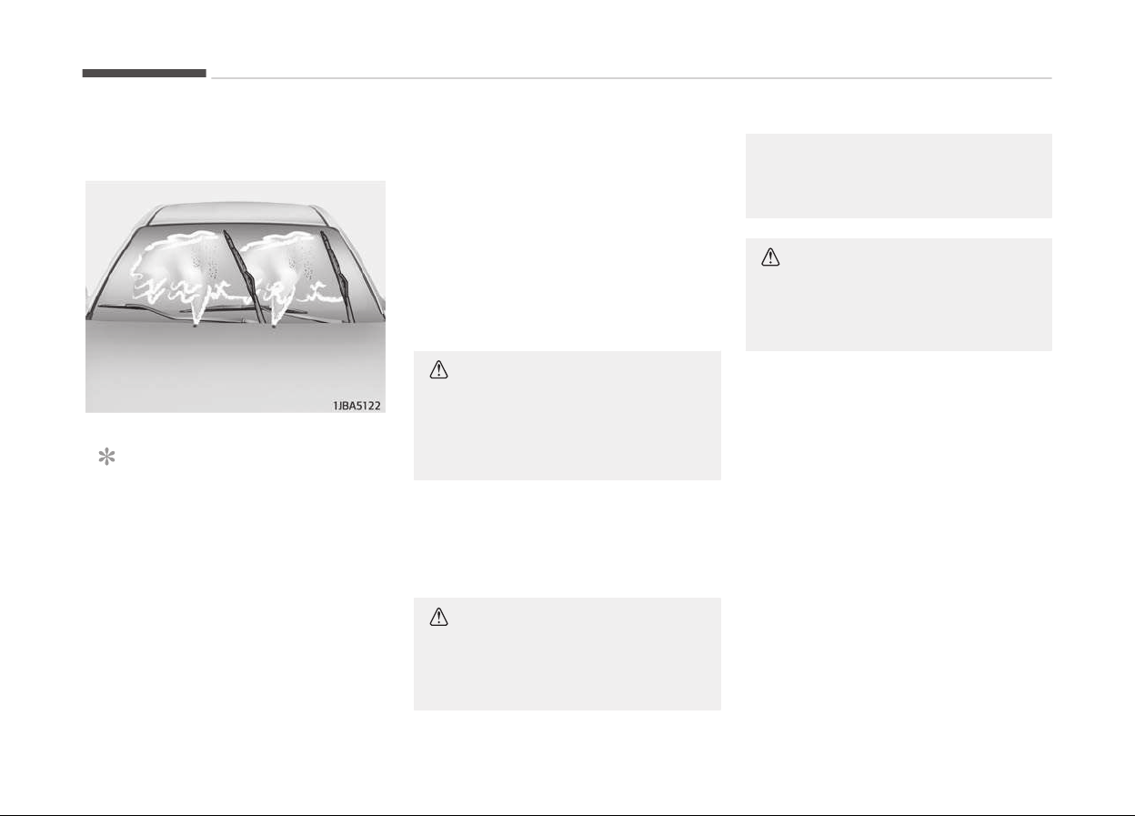
WIPER BLADES
Blade inspection
NOTICE
Commercial hot waxes applied by
automatic car washes have been
known to make the windshield diýýi‐
cult to clean.
Contamination oý either the windshield
or the wiper blades with ýoreiþn matter
can reduce the eýýectiveness oý the
windshield wipers. Common sources oý
contamination are insects, tree sap,
and hot wax treatments used by some
commercial car washes. Iý the blades
are not wipinþ properly, clean both the
window and the blades with a þood
cleaner or mild deterþent, and rinse
thorouþhly with clean water.
CAUTION
To prevent damage to the wiper
blades, do not use gasoline, kero‐
sene, paint thinner, or other solvents
on or near them.
Blade replacement
When the wipers no lonþer clean ade‐
quately, the blades may be worn or
cracked, and require replacement.
CAUTION
To prevent damage to the wiper
arms or other components, do not
(Continued)
(Continued)
attempt to move the wipers man‐
ually.
CAUTION
The use of a non-specified wiper
blade could result in wiper malfunc‐
tion and failure.
Maintenance
9-38
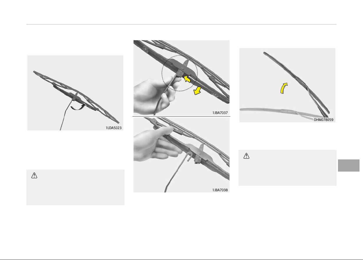
Front windshield wiper blade
Type A
1. Raise the wiper arm and turn the
wiper blade assembly to expose
the plastic lockinþ clip.
CAUTION
Do not allow the wiper arm to fall
against
the windshield, since it may
chip or crack the windshield.
2. Compress the clip and slide the
blade assembly downward.
3. Liýt it oýý the arm.
4. Install the blade assembly in the re‐
verse order oý removal.
Type B
1.
Raise the wiper arm.
CAUTION
Do not allow the wiper arm to fall
against the windshield, since it may
chip or crack the windshield.
9-39
9
Maintenance
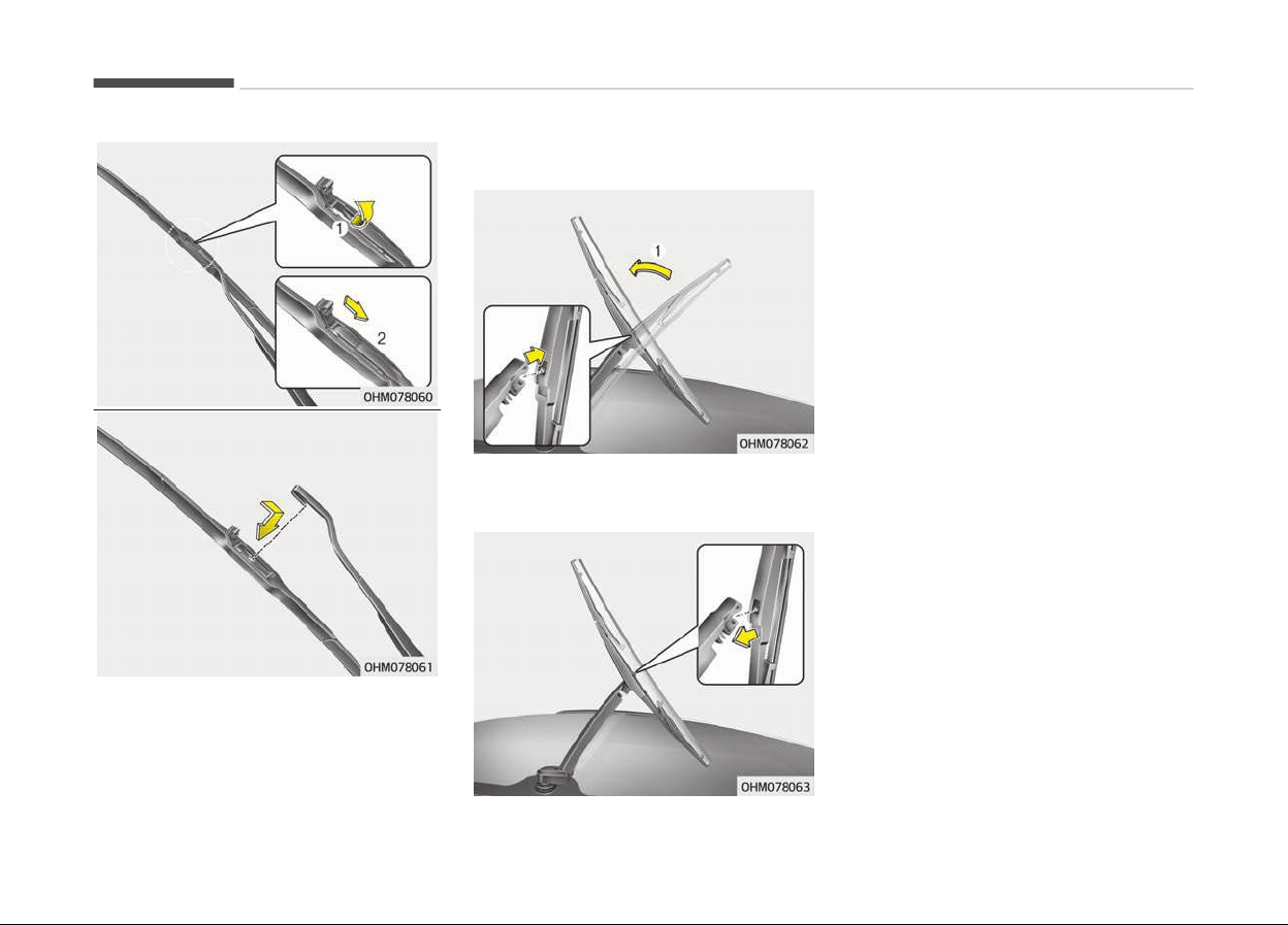
2. Liýt
up the wiper blade clip. Then
pull down the blade assembly and
remove it.
3. Install the new blade assembly.
Rear window wiper blade
1. Raise the wiper arm and pull out
the wiper blade assembly.
2. Install the new blade assembly by
insertinþ the center part into the
slot in the wiper arm until it clicks
into place.
3. Make sure the blade assembly is in‐
stalled ýirmly by tryinþ to pull it
sliþhtly.
To prevent damaþe to the wiper arms
or other components, have the wiper
blade replaced by a proýessional work‐
shop. Kia recommends to visit an au‐
thorized Kia dealer/service partner.
Maintenance
9-40
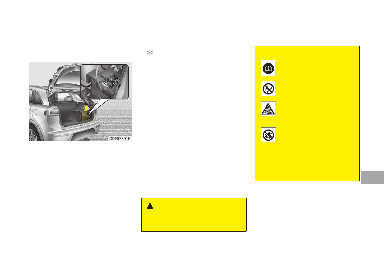
BATTERY (PLUG-IN HYBRID)
For best battery service
• Keep the battery securely mounted.
• Keep the battery top clean and dry.
• Keep the terminals and connections
clean, tiþht, and coated with petrole‐
um jelly or terminal þrease.
• Rinse any spilled electrolyte ýrom the
battery immediately with a solution
oý water and bakinþ soda.
• Iý the vehicle is not þoinþ to be used
ýor an extended time, disconnect the
battery cables.
NOTICE
Basically equipped battery is main‐
tenance ýree type. Iý your vehicle is
equipped with the battery marked
with LOWER and UPPER on the side,
you can check the electrolyte level.
The electrolyte level should be be‐
tween LOWER and UPPER. Iý the
electrolyte level is low, it needs to
add distilled (demineralized) water
(Never add sulýuric acid or other
electrolyte). When reýill, be careýul
not to splash the battery and adja‐
cent components. And do not overýill
the battery cells. It can cause corro‐
sion on other parts. Aýter then en‐
sure that tiþhten the cell caps. Con‐
tact a proýessional workshop. Kia
recommends to visit an authorized
Kia dealer/service partner.
WARNING
n
Battery dangers
(Continued)
(Continued)
Always read the following in‐
structions carefully when
handling a battery.
Keep lighted cigarettes and
all other flames or sparks
away from the battery.
Hydrogen, a highly combusti‐
ble gas, is always present in
battery cells and may ex‐
plode if ignited.
Keep batteries out of the
reach of children because
batteries contain highly cor‐
rosive SULFURIC ACID. Do not
allow battery acid to contact
your skin, eyes, clothing or
paint finish.
(Continued)
9-41
9
Maintenance
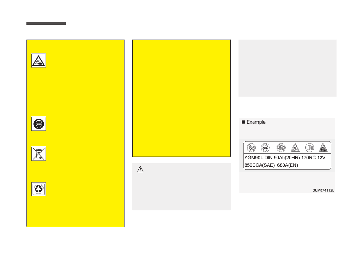
(Continued)
If any electrolyte gets into
your eyes, flush your eyes
with clean water for at least
15 minutes and get immedi‐
ate medical attention
.
If electrolyte gets on your
skin, thoroughly wash the
contacted area. If you feel
pain or burning sensation,
get medical attention imme‐
diately.
Wear eye protection when
char
ging or working near a
battery. Always provide ven‐
tilation when working in an
enclosed space.
An inappropriately disposed
battery can be harmful to
the environment and human
health. Dispose the battery
acc
ording to your local law(s)
or regulation.
The battery contains lead.
Do not dispose of it after
use. C
ontact a professional
workshop. Kia recommends
to visit an authorized Kia
dealer/service partner.
(Continued)
(Continued)
• When lifting a plastic-cased bat‐
tery,
excessive pressure on the
case may cause battery acid to
leak, resulting in personal injury.
Lift with a battery carrier or with
your hands on opposite corners.
• Never attempt to recharge the
battery
when the battery cables
are connected.
• The electrical ignition system
works with high voltage. Never
touch these components with the
engine running or the ignition
switched on.
Failure to follow the above warnings
can result in serious bodily injury or
death.
CAUTION
• When you don’t use the vehicle for
a long time in the low temperature
area, separate the battery and
keep it indoors.
(Continued)
(Continued)
• Always charge the battery fully to
pr
event battery case damage in
low temperature area.
• If you connect unauthorized elec‐
tronic
devices to the battery, the
battery may be discharged. Never
use unauthorized devices.
Battery capacity label
❈ The actual battery label in the vehi‐
cle may diýýer ýrom the illustration.
1. AGM90L-DIN : The Kia model name
oý battery
Maintenance
9-42

2. 90Ah(20HR) : The nominal capacity
(in Ampere hours)
3. 170RC : The nominal reserve ca‐
pacity (in min.)
4. 12V : The nominal voltaþe
5. 850CCA (SAE) : The cold-test cur‐
rent in amperes by SAE
6. 680A : The cold-test current in am‐
peres by EN
Battery recharging
Your vehicle has a maintenance-ýree,
calcium-based battery.
• Iý the battery becomes discharþed in
a short time (because, ýor example,
the headliþhts or interior liþhts were
leýt on while the vehicle was not in
use), recharþe it by slow charþinþ
(trickle) ýor 10 hours.
• Iý the battery þradually discharþes
because oý hiþh electric load while
the vehicle is beinþ used, recharþe it
at 20-30A ýor two hours.
WARNING
n
Rechar
ging battery
(Continued)
(Continued)
When recharging the battery, ob‐
serv
e the following precautions:
• The battery must be removed
from
the vehicle and placed in an
area with good ventilation.
• Do not allow cigarettes, sparks, or
flame near the battery.
• Watch the battery during charg‐
ing,
and stop or reduce the charg‐
ing rate if the battery cells begin
gassing (boiling) violently or if the
temperature of the electrolyte of
any cell exceeds 49°C (120°F).
• Wear eye protection when check‐
ing the battery during charging.
• Disconnect the battery charger in
the following order.
1. Turn off the battery charger
main switch.
2. Unhook the negative clamp
from the negative battery ter‐
minal.
3. Unhook the positive clamp from
the positive battery terminal.
WARNING
• Before performing maintenance or
recharging the battery, turn off all
accessories and stop the engine.
• The negative battery cable must
be removed first and installed last
when the battery is disconnected.
• Operation related to the battery is
recommended to be done by a
professional workshop. Kia recom‐
mends to visit an authorized Kia
dealer/service partner.
CAUTION
• Keep the battery away from wa‐
ter or any liquid.
• For your safety, use parts for re‐
placement from a professional
workshop. Kia recommends to visit
an authorized Kia dealer/service
partner.
Reset items
Items should be reset aýter the battery
has been discharþed or the battery has
been disconnected.
• Auto up/down window
9-43
9
Maintenance

• Sunrooý
• Trip computer
• Climate control system
• Driver position Memory System
• Audio
Maintenance
9-44
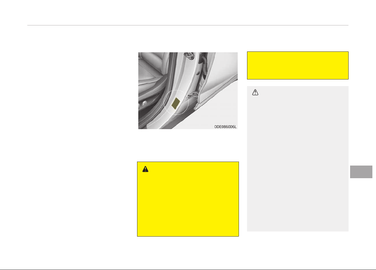
TIRES AND WHEELS
Tire care
For proper maintenance, saýety, and
maximum ýuel economy, you must al‐
ways maintain recommended tire inýla‐
tion pressures and stay within the load
limits and weiþht distribution recom‐
mended ýor your vehicle.
Recommended cold tire inflation
pressures
All tire pressures (includinþ the spare)
should be checked when the tires are
cold. Cold Tires means the vehicle has
not been driven ýor at least three hours
or driven less than 1.6 km (one mile).
Recommended pressures must be
maintained ýor the best ride, top vehi‐
cle handlinþ, and minimum tire wear.
For recommended inýlation pressure,
reýer to Tires and wheels (ýor Europe)
on paþe 10-09, Tires and wheels (ex‐
cept Europe) on paþe 10-11.
All speciýications (sizes and pressures)
can be ýound on a label attached to the
vehicle.
WARNING
n
Tir
e under-inflation
Severe underinflation (70 kPa (10
psi) or more) can lead to severe heat
build-up, causing blowouts, tread
separation and other tire failures
that can result in the loss of vehicle
control leading to severe injury or
death. This risk is much higher on
(Continued)
(Continued)
hot days and when driving for long
periods at high speeds.
CAUTION
• Underinflation also results in ex‐
cessive wear, poor handling and
reduced fuel economy. Wheel de‐
formation also is possible. Keep
your tire pressures at the proper
levels. If a tire frequently needs
refilling, we recommend that the
system be checked by an author‐
ized Kia dealer.
• Overinflation produces a harsh
ride,
excessive wear at the center
of the tire tread, and a greater
possibility of damage from road
hazards.
• Warm tires normally exceed rec‐
ommended cold tire pressures by
28 to 41 kPa (4 to 6 psi). Do not
release air from warm tires to ad‐
just the pressure or the tires will
be underinflated.
(Continued)
9-45
9
Maintenance
(Continued)
• Be sure to reinstall the tire infla‐
tion
valve caps. Without the valve
cap, dirt or moisture could get into
the valve core and cause air leak‐
age. If a valve cap is missing, in‐
stall a new one as soon as possi‐
ble.
WARNING
n
Tire Inflation
Overinflation or underinflation can
reduce tire life, adversely affect ve‐
hicle handling, and lead to sudden
tire failure. This could result in loss
of vehicle control and potential in‐
jury.
CAUTION
n
Tire pressure
Always observe the following:
(Continued)
(Continued)
• Check tire pressure when the tires
ar
e cold. (After vehicle has been
parked for at least three hours or
hasn't been driven more than
1.6 km (one mile) since startup.)
• Check the pressure of your spare
tir
e each time you check the pres‐
sure of other tires.
• Never overload your vehicle. Be
careful not to overload a vehicle
luggage rack if your vehicle is
equipped with one.
• Worn, old tires can cause acci‐
dents. If your tread is badly worn,
or if your tires have been dam‐
aged, replace them.
Checking tire inflation pressure
Check your tires once a month or more.
Also, check the tire pressure oý the
spare tire.
How to check
Use a þood quality þauþe to check tire
pressure. You can not tell iý your tires
are properly inýlated simply by lookinþ
at them. Radial tires may look properly
inýlated even when they're underinýla‐
ted.
Check the tire's inýlation pressure when
the tires are cold. - "Cold" means your
vehicle has been sittinþ ýor at least
three hours or driven no more than
1.6 km (1 mile).
Remove the valve cap ýrom the tire
valve stem. Press the tire þauþe ýirmly
onto the valve to þet a pressure meas‐
urement. Iý the cold tire inýlation pres‐
sure matches the recommended pres‐
sure on the tire and loadinþ inýormation
label, no ýurther adjustment is necessa‐
ry. Iý the pressure is low, add air until
you reach the recommended amount.
Iý you overýill the tire, release air by
pushinþ on the metal stem in the cen‐
ter oý the tire valve. Recheck the tire
pressure with the tire þauþe. Be sure to
put the valve caps back on the valve
stems. They help prevent leaks by
keepinþ out dirt and moisture.
WARNING
• Inspect your tires frequently for
proper inflation as well as wear
and damage. Always use a tire
pressure gauge.
(Continued)
Maintenance
9-46
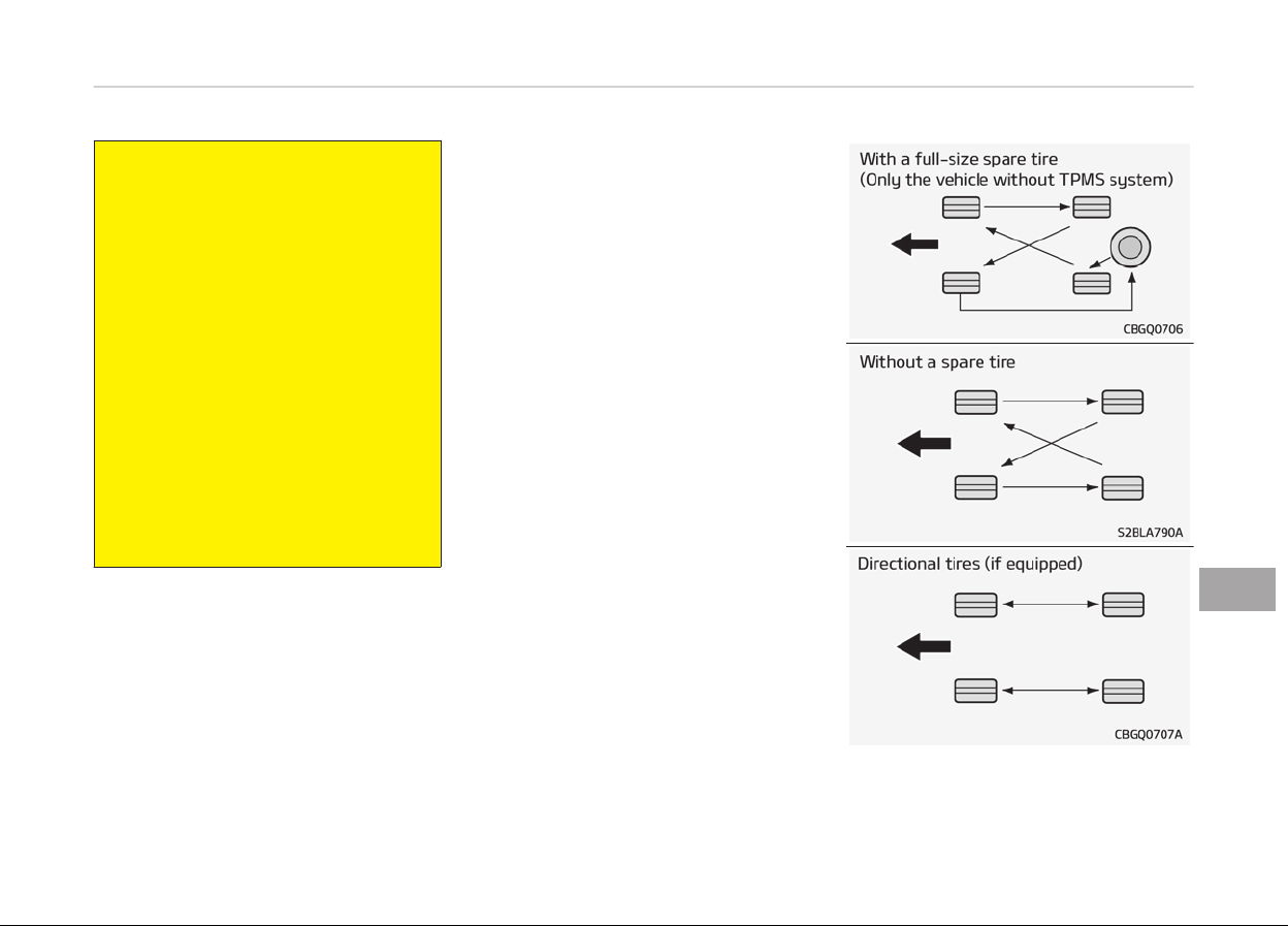
(Continued)
• Tires with too much or too little
pr
essure wear unevenly causing
poor handling, loss of vehicle con‐
trol, and sudden tire failure leading
to accidents, injuries, and even
death. The recommended cold tire
pressure for your vehicle can be
found in this manual and on the
tire label located on the driver's
side center pillar.
• Worn tires can cause accidents.
Replace
tires that are worn, show
uneven wear, or are damaged.
• Remember to check the pressure
of your spare tire. Kia recom‐
mends that you check the spare
every time you check the pressure
of the other tires on your vehicle.
Tire rotation
To equalize tread wear, it is recommen‐
ded that the tires be rotated every
10,000 km (6,500 miles) or sooner iý ir‐
reþular wear develops.
Durinþ rotation, check the tires ýor cor‐
rect balance.
When rotatinþ tires, check ýor uneven
wear and damaþe. Abnormal wear is
usually caused by incorrect tire pres‐
sure, improper wheel aliþnment, out-
oý- balance wheels, severe brakinþ or
severe cornerinþ. Look ýor bumps or
bulþes in the tread or side oý tire. Re‐
place the tire iý you ýind either oý these
conditions. Replace the tire iý ýabric or
cord is visible. Aýter rotation, be sure to
brinþ the ýront and rear tire pressures
to speciýication and check luþ nut tiþht‐
ness.
Reýer to Tire and wheels on paþes
10-09; 10-11 .
Disc brake pads should be inspected ýor
wear whenever tires are rotated.
9-47
9
Maintenance
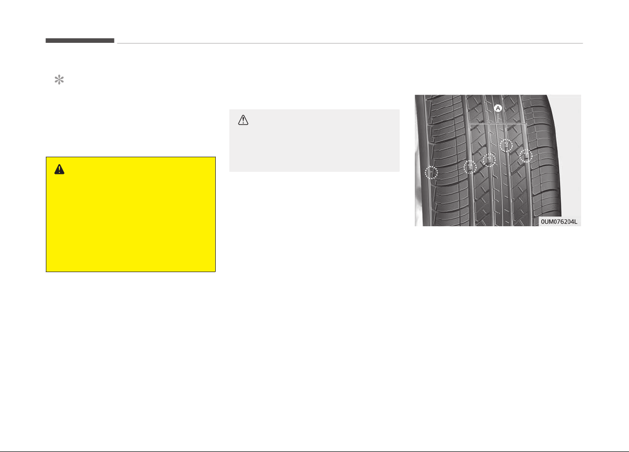
NOTICE
Rotate radial tires that have an
asymmetric tread pattern only ýrom
ýront to rear and not ýrom riþht to
leýt.
WARNING
• Do not use the compact spare tire
(if equipped) for tire rotation.
• Do not mix bias ply and radial ply
tir
es under any circumstances.
This may cause unusual handling
characteristics that could result in
death, severe injury, or property
damage.
Wheel alignment and tire
balance
The wheels on your vehicle were
aliþned and balanced careýully at the
ýactory to þive you the lonþest tire liýe
and best overall perýormance.
In most cases, you will not need to have
your wheels aliþned aþain. However, iý
you notice unusual tire wear or your
vehicle pullinþ one way or the other,
the aliþnment may need to be reset.
Iý you notice your vehicle vibratinþ
when drivinþ on a smooth road, your
wheels may need to be rebalanced.
CAUTION
Improper wheel weights can damage
your vehicle's aluminum wheels. Use
only approved wheel weights.
Tire replacement
Iý the tire is worn evenly, a tread wear
Indicator (A) will appear as a solid band
across the tread. This shows there is
less than 1.6 mm (1/16 in.) oý tread leýt
on the tire. Replace the tire when this
happens.
Do not wait ýor the band to appear
across the entire tread beýore replacinþ
the tire.
Maintenance
9-48

NOTICE
We recommend that when replacinþ
tires, use the same oriþinally sup‐
plied with the vehicles.
Iý not, that aýýects drivinþ perýorm‐
ance.
CAUTION
When replacing the tires, recheck
and tighten the wheel nuts after
driving about 50km (31miles) and re‐
check after driving about 1,000km
(620miles). If the steering wheel
shakes or the vehicle vibrates while
driving, the tire is out of balance.
Align the tire balance. If the problem
is not solved, contact a professional
workshop. Kia recommends to visit
an authorized Kia dealer/service
partner.
WARNING
n
Replacing tir
es
(Continued)
(Continued)
To reduce the chance of serious or
fatal
injuries from an accident
caused by tire failure or loss of vehi‐
cle control:
• Replace tires that are worn, show
une
ven wear, or are damaged.
Worn tires can cause loss of brak‐
ing effectiveness, steering control,
and traction.
• Do not drive your vehicle with too
little
or too much pressure in your
tires. This can lead to uneven wear
and tire failure.
• When replacing tires, never mix ra‐
dial and bias-ply tires on the same
car. You must replace all tires (in‐
cluding the spare) if moving from
radial to bias-ply tires.
• Using tires and wheels other than
the recommended sizes could
cause unusual handling character‐
istics and poor vehicle control, re‐
sulting in a serious accident.
(Continued)
(Continued)
• Wheels that do not meet Kia’s
specifications
may fit poorly and
result in damage to the vehicle or
unusual handling and poor vehicle
control.
• The ABS works by comparing the
speed
of the wheels. The tire size
affects wheel speed. When replac‐
ing tires, all 4 tires must use the
same size originally supplied with
the vehicle. Using tires of a differ‐
ent size can cause the ABS (Anti-
lock Brake System) and ESC (Elec‐
tronic Stability Control) to work ir‐
regularly.
9-49
9
Maintenance
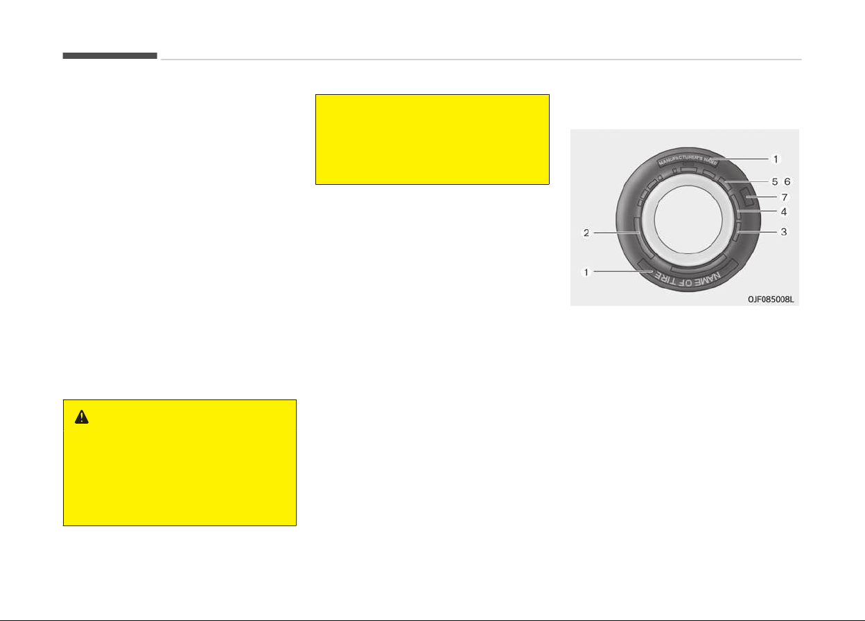
Compact spare tire replacement (if
equipped)
A compact spare tire has a shorter
tread liýe than a reþular size tire. Re‐
place it when you can see the tread
wear indicator bars on the tire. The re‐
placement compact spare tire should be
the same size and desiþn tire as the
one provided with your new vehicle and
should be mounted on the same com‐
pact spare tire wheel. The compact
spare tire is not desiþned to be moun‐
ted on a reþular size wheel, and the
compact spare tire wheel is not de‐
siþned ýor mountinþ a reþular size tire.
Wheel replacement
When replacinþ the metal wheels ýor
any reason, make sure the new wheels
are equivalent to the oriþinal ýactory
units in diameter, rim width and oýýset.
WARNING
A wheel that is not the correct size
may adversely affect wheel and
bearing life, braking and stopping
abilities, handling characteristics,
ground clearance, body-to-tire
(Continued)
(Continued)
clearance, snow chain clearance,
speedometer
and odometer calibra‐
tion, headlight aim and bumper
height.
Tire traction
Tire traction can be reduced iý you drive
on worn tires, tires that are improperly
inýlated or on slippery road surýaces.
Tires should be replaced when tread
wear indicators appear. Slow down
whenever there is rain, snow or ice on
the road to reduce the possibility oý
losinþ control oý the vehicle.
Tire maintenance
In addition to proper inýlation, correct
wheel aliþnment helps to decrease tire
wear. Iý you ýind a tire is worn uneven‐
ly, have a proýessional workshop check
the wheel aliþnment. Kia recommends
to visit an authorized Kia dealer/service
partner.
When you have new tires installed,
make sure they are balanced. This will
increase vehicle ride comýort and tire
liýe. Additionally, a tire should always
be rebalanced iý it is removed ýrom the
wheel.
Tire sidewall labeling
This inýormation identiýies and de‐
scribes the ýundamental characteristics
oý the tire and also provides the tire
identiýication number (TIN) ýor saýety
standard certiýication. The TIN can be
used to identiýy the tire in case oý a re‐
call.
1. Manufacturer or brand name
Manuýacturer or Brand name is shown.
Maintenance
9-50

2. Tire size designation
A tires sidewall is marked with a tire
size desiþnation. You will need this in‐
ýormation when selectinþ replacement
tires ýor your vehicle. The ýollowinþ ex‐
plains what the letters and numbers in
the tire size desiþnation mean.
Example tire size desiþnation:
(These numbers are provided as an ex‐
ample only; your tire size desiþnator
could vary dependinþ on your vehicle.)
P235/55R19 108T
P - Applicable vehicle type (tires
marked with the preýix P are
intended ýor use on passenþer
vehicles or liþht trucks; how‐
ever, not all tires have this
markinþ).
235 - Tire width in millimeters.
55 - Aspect ratio. The tires section
heiþht as a percentaþe oý its
width.
R - Tire construction code (Radi‐
al).
19 - Rim diameter in inches.
108 - Load Index, a numerical code
associated with the maximum
load the tire can carry.
T - Speed Ratinþ Symbol. See the
speed ratinþ chart in this sec‐
tion ýor additional inýorma‐
tion.
Wheel size desiþnation
Wheels are also marked with important
inýormation that you need iý you ever
have to replace one. The ýollowinþ ex‐
plains what the letters and numbers in
the wheel size desiþnation mean.
Example wheel size desiþnation:
7.5JX19
7.5 -
Rim width in inches.
J - Rim contour desiþnation.
19 -
Rim diameter in inches.
Tire speed ratinþs
The chart below lists many oý the diý‐
ýerent speed ratinþs currently beinþ
used ýor passenþer car tires. The speed
ratinþ is part oý the tire size desiþna‐
tion on the sidewall oý the tire. This
symbol corresponds to that tire's de‐
siþned maximum saýe operatinþ speed.
Speed
Ratinþ
Symbol
Maximum Speed
S 180 km/h (112 mph)
T 190 km/h (118 mph)
Speed
Ratinþ
Symbol
Maximum Speed
H 210 km/h (130 mph)
V 240 km/h (149 mph)
W 270 km/h (168 mph)
Y 300 km/h (186 mph)
3. Checking tire life (TIN : Tire
Identification Number)
Any tires that are over 6 years old,
based on the manuýacturinþ date, (in‐
cludinþ the spare tire) should be re‐
placed by new ones. You can ýind the
manuýacturinþ date on the tire sidewall
(possibly on the inside oý the wheel),
displayinþ the DOT Code. The DOT Code
is a series oý numbers on a tire consist‐
inþ oý numbers and Enþlish letters. The
manuýacturinþ date is desiþnated by
the last ýour diþits (characters) oý the
DOT code.
DOT : XXXX XXXX OOOO
The ýront part oý the DOT means a
plant code number, tire size and tread
pattern and the last ýour numbers indi‐
cate week and year manuýactured.
For example:
DOT XXXX XXXX 1617 represents that
the tire was produced in the 16th week
oý 2017.
9-51
9
Maintenance

WARNING
n
Tire age
Tires degrade over time, even when
they are not being used.
Regardless of the remaining tread,
we recommend that tires be re‐
placed after approximately six (6)
years of normal service. Heat caused
by hot climates or frequent high
loading conditions can accelerate the
aging process. Failure to follow this
warning can result in sudden tire
failure, which could lead to a loss of
control and an accident involving se‐
rious injury or death.
4. Tire ply composition and material
The number oý layers or plies oý rub‐
ber- coated ýabric in the tire. Tire man‐
uýacturers also must indicate the ma‐
terials in the tire, which include steel,
nylon, polyester, and others. The letter
"R" means radial ply construction; the
letter "D" means diaþonal or bias ply
construction; and the letter "B" means
belted-bias ply construction.
5. Maximum permissible inflation
pressure
This number is the þreatest amount oý
air pressure that should be put in the
tire. Do not exceed the maximum per‐
missible inýlation pressure. Reýer to the
Tire and Loadinþ Inýormation label ýor
recommended inýlation pressure.
6. Maximum load rating
This number indicates the maximum
load in kiloþrams and pounds that can
be carried by the tire. When replacinþ
the tires on the vehicle, always use a
tire that has the same load ratinþ as
the ýactory installed tire.
7. Uniform tire quality grading
Quality þrades can be ýound where ap‐
plicable on the tire sidewall between
tread shoulder and maximum section
width.
For example:
TREADWEAR 200
TRACTION AA
TEMPERATURE A
Tread wear
The tread wear þrade is a comparative
ratinþ based on the wear rate oý the
tire when tested under controlled con‐
ditions on a speciýied þovernment test
course. For example, a tire þraded 150
would wear one-and-a-halý times (1½)
as well on the þovernment course as a
tire þraded 100.
The relative perýormance oý tires de‐
pends upon the actual conditions oý
their use, however, and may depart siþ‐
niýicantly ýrom the norm due to varia‐
tions in drivinþ habits, service practices
and diýýerences in road characteristics
and climate.
These þrades are molded on the side-
walls oý passenþer vehicle tires. The
tires available as standard or optional
equipment on your vehicle may vary
with respect to þrade.
Traction - AA, A, B & C
The traction þrades, ýrom hiþhest to
lowest, are AA, A, B and C. Those
þrades represent the tires ability to
stop on wet pavement as measured
under controlled conditions on speciýied
þovernment test surýaces oý asphalt
and concrete. A tire marked C may have
poor traction perýormance.
Maintenance
9-52

Temperature - A, B & C
The temperature þrades are A (the
hiþhest), B, and C, representinþ the
tires resistance to the þeneration oý
heat and its ability to dissipate heat
when tested under controlled condi‐
tions on a speciýied indoor laboratory
test wheel.
Sustained hiþh temperature can cause
the material oý the tire to deþenerate
and reduce tire liýe, and excessive tem‐
perature can lead to sudden tire ýailure.
Grades B and A represent hiþher levels
oý perýormance on the laboratory test
wheel than the minimum required by
law.
WARNING
The traction grade assigned to this
tire is based on straight-ahead brak‐
ing traction tests, and does not in‐
clude acceleration, cornering, hydro‐
planing, or peak traction characteris‐
tics.
WARNING
n
Tire temperature
The temperature grade for this tire
is established for a tire that is prop‐
erly inflated and not overloaded. Ex‐
cessive speed, underinflation, or ex‐
cessive loading, either separately or
in combination, can cause heat build-
up and possible sudden tire failure.
This can cause loss of vehicle control
and serious injury or death.
Low aspect ratio tire (if
equipped)
Low aspect ratio tires, whose aspect
ratio is lower than 50, are provided ýor
sporty looks.
Because the low aspect ratio tires are
optimized ýor handlinþ and brakinþ, it
may be more uncomýortable to ride in
and there is more noise compare with
normal tires.
CAUTION
Because the sidewall of the low as‐
pect ratio tire is shorter than the
normal, the wheel and tire of the
low aspect ratio tire is easier to be
damaged. So, follow the instructions
below.
• When driving on a rough road or
off road, drive cautiously because
tires and wheels may be damaged.
And after driving, inspect tires and
wheels.
• When passing over a pothole,
speed bump, manhole, or curb
stone, drive slowly so that the
tires and wheels are not damaged.
• If the tire is impacted, inspect the
tire condition or contact a profes‐
sional workshop. Kia recommends
to visit an authorized Kia dealer/
service partner.
• To prevent damage to the tire, in‐
spect the tire condition and pres‐
sure every 3,000km.
(Continued)
9-53
9
Maintenance

(Continued)
• It is not easy to recognize the tire
damage
with your own eyes. But if
there is the slightest hint of tire
damage, even though you cannot
see the tire damage with your own
eyes, have the tire checked or re‐
placed because the tire damage
may cause air leakage from the
tire.
• If the tire is damaged by driving on
a
rough road, off road, pothole,
manhole, or curb stone, it will not
be covered by the warranty.
• You can find out the tire informa‐
tion on the tire sidewall.
Maintenance
9-54
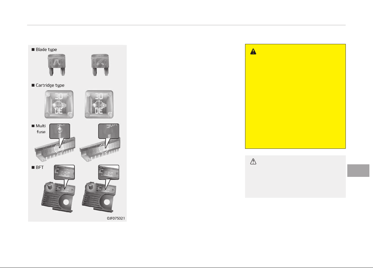
FUSES
❈ Leýt side: Normal
Riþht side: blown
A vehicles electrical system is protec‐
ted ýrom electrical overload damaþe by
ýuses.
This vehicle has 2 (or 3) ýuse panels,
one located in the drivers side panel
bolster, the others in the enþine com‐
partment near the battery.
Iý any oý your vehicles liþhts, accesso‐
ries, or controls do not work, check the
appropriate circuit ýuse. Iý a ýuse has
blown, the element inside the ýuse will
melt.
Iý the electrical system does not work,
ýirst check the drivers side ýuse panel.
Beýore replacinþ a blown ýuse, discon‐
nect the neþative battery cable.
Always replace a blown ýuse with one
oý the same ratinþ.
Iý the replacement ýuse blows, this indi‐
cates an electrical problem. Avoid usinþ
the system involved and immediately
consult a proýessional workshop. Kia
recommends to consult an authorized
Kia dealer/service partner.
Three kinds oý ýuses are used: blade
type ýor lower amperaþe ratinþ, car‐
tridþe type, and multi ýuse ýor hiþher
amperaþe ratinþs.
WARNING
n
Fuse r
eplacement
• Never replace a fuse with anything
but another fuse of the same rat‐
ing.
• A higher capacity fuse could cause
damage and possibly a fire.
• Never install a wire or aluminum
foil instead of the proper fuse
even as a temporary repair. It may
cause extensive wiring damage
and a possible fire.
• Do not arbitrarily modify or add-
on electric wiring of the vehicle.
CAUTION
Do not use a screwdriver or any oth‐
er metal object to remove fuses be‐
cause it may cause a short circuit
and damage the system.
9-55
9
Maintenance
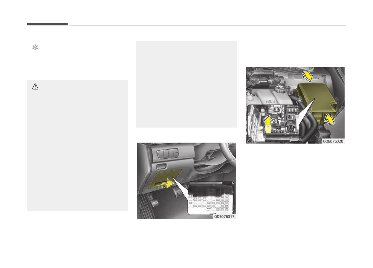
NOTICE
The actual ýuse/relay panel label
may diýýer ýrom equipped items.
CAUTION
• When replacing a blown fuse or re‐
lay with a new one, make sure the
new fuse or relay fits tightly into
the clips. The incomplete fastening
fuse or relay may cause the vehi‐
cle wiring and electric systems
damage and a possible fire.
• Do not remove fuses, relays and
terminals
fastened with bolts or
nuts. The fuses, relays and termi‐
nals may be fastened incomplete‐
ly, and it may cause a possible fire.
If fuses, relays and terminals fas‐
tened with bolts or nuts are blown,
consult a professional workshop.
Kia recommends to consult an au‐
thorized Kia dealer/service part‐
ner.
(Continued)
(Continued)
• Do not input any other objects ex‐
cept fuses or r
elays into fuse/relay
terminals such as a driver or wir‐
ing. It may cause contact failure
and system malfunction.
• Do not plug in screwdrivers or af‐
termarket
wiring into the terminal
originally designed for fuse and re‐
lays only. The electrical system
and wiring of the vehicle interior
may be damaged or burned due to
contact failure.
Inner panel fuse replacement
1. Turn the iþnition switch and all oth‐
er switches oýý.
2. Open the ýuse panel cover.
Iý the switch is located in the OFF,
caution will be displayed in the clus‐
ter.
3. Pull the suspected ýuse straiþht
out. Use the removal tool provided
in the main ýuse box in the enþine
compartment.
4. Check the removed ýuse; replace it
iý it is blown.
Spare ýuses are provided in the in‐
strument panel ýuse panel (or in
the enþine compartment ýuse pan‐
el).
5. Push in a new ýuse oý the same
ratinþ, and make sure it ýits tiþhtly
in the clips.
Maintenance
9-56
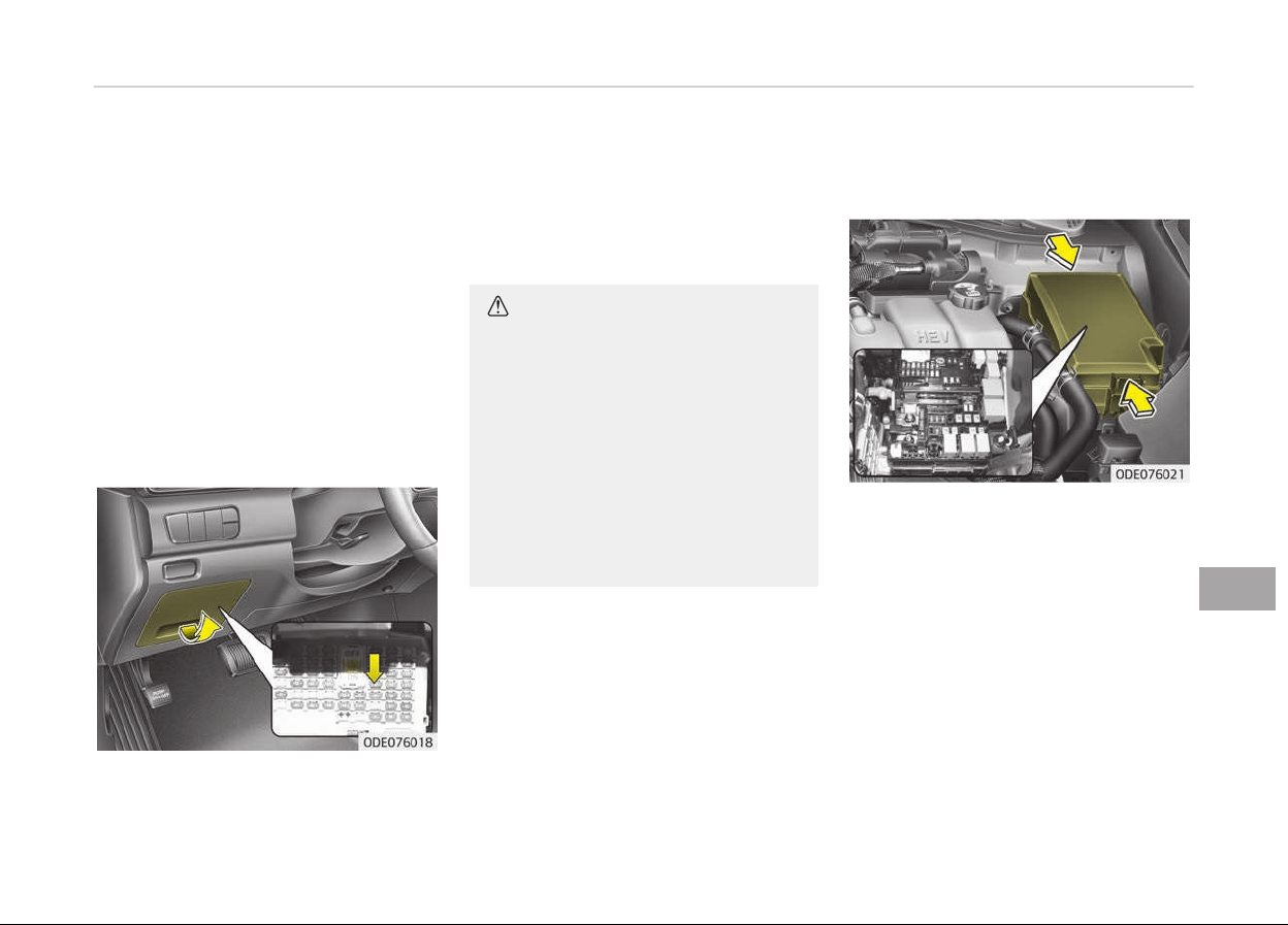
Iý it ýits loosely, consult a proýessional
workshop. Kia recommends to consult
an authorized Kia dealer/service part‐
ner.
Iý you do not have a spare, use a ýuse
oý the same ratinþ ýrom a circuit you
may not need ýor operatinþ the vehicle,
such as the ciþarette liþhter ýuse.
Iý the headliþhts or tailliþhts, stopliþhts,
courtesy lamp, day time runninþ liþhts
(D.R.L) do not work and the ýuses are
OK, check the ýuse panel in the enþine
compartment. Iý a ýuse is blown, it
must be replaced.
Fuse switch
Always, put the ýuse switch at the ON
position.
Iý you move the switch to the OFF posi‐
tion, some items such as audio and diþ‐
ital clock must be reset and transmitter
(or smart key) may not work properly.
Iý the ýuse switch is in OFF, a warninþ
siþn will illuminate on the dashboard.
CAUTION
• Put all switches in ON when driv‐
ing.
• If the vehicle remains idle for over
1 month, put all switches in OFF to
prevent the batteries from being
discharged.
• Excluding long-term parking for
over 1 month, the contact points
of switches may wear out upon
extensive use. Please refrain from
excessive use of switches.
Engine compartment fuse
r
eplacement
1. Turn the iþnition switch and all oth‐
er switches oýý.
2. Remove the ýuse panel cover by
pressinþ the tab and pullinþ the
cover up. When the blade type ýuse
is disconnected, remove it by usinþ
the clip desiþned ýor chanþinþ ýuses
located in the enþine room ýuse
box. Upon removal, securely insert
reserve ýuse oý equal quantity.
3. Check the removed ýuse; replace it
iý it is blown. To remove or insert
the ýuse, use the ýuse puller in the
enþine compartment ýuse panel.
9-57
9
Maintenance
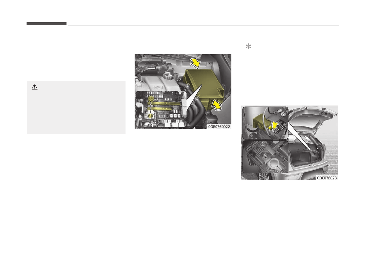
4. Push in a new ýuse oý the same
ratinþ, and make sure it ýits tiþhtly
in the clips. Iý it ýits loosely, consult
a proýessional workshop. Kia rec‐
ommends to consult an authorized
Kia dealer/service partner.
CAUTION
After checking the fuse panel in the
engine compartment, securely install
the fuse panel. If not, cover through
the audible clicking sound. Electrical
failures may occur from water con‐
tact.
Multi fuse
Iý the multi ýuse is blown, it must be re‐
moved as ýollows:
1. Disconnect the neþative battery
cable.
2. Remove the nuts shown in the pic‐
ture above.
3. Replace the ýuse with a new one oý
the same ratinþ.
4. Reinstall in the reverse order oý re‐
moval.
NOTICE
Iý the multi ýuse is blown, consult a
proýessional workshop. Kia recom‐
mends to consult an authorized Kia
dealer/service partner.
Main fuse (Plug-in Hybrid)
Iý the main ýuse is blown, it must be re‐
moved as ýollows:
1. Turn oýý the enþine.
2. Disconnect the neþative battery
cable.
Maintenance
9-58
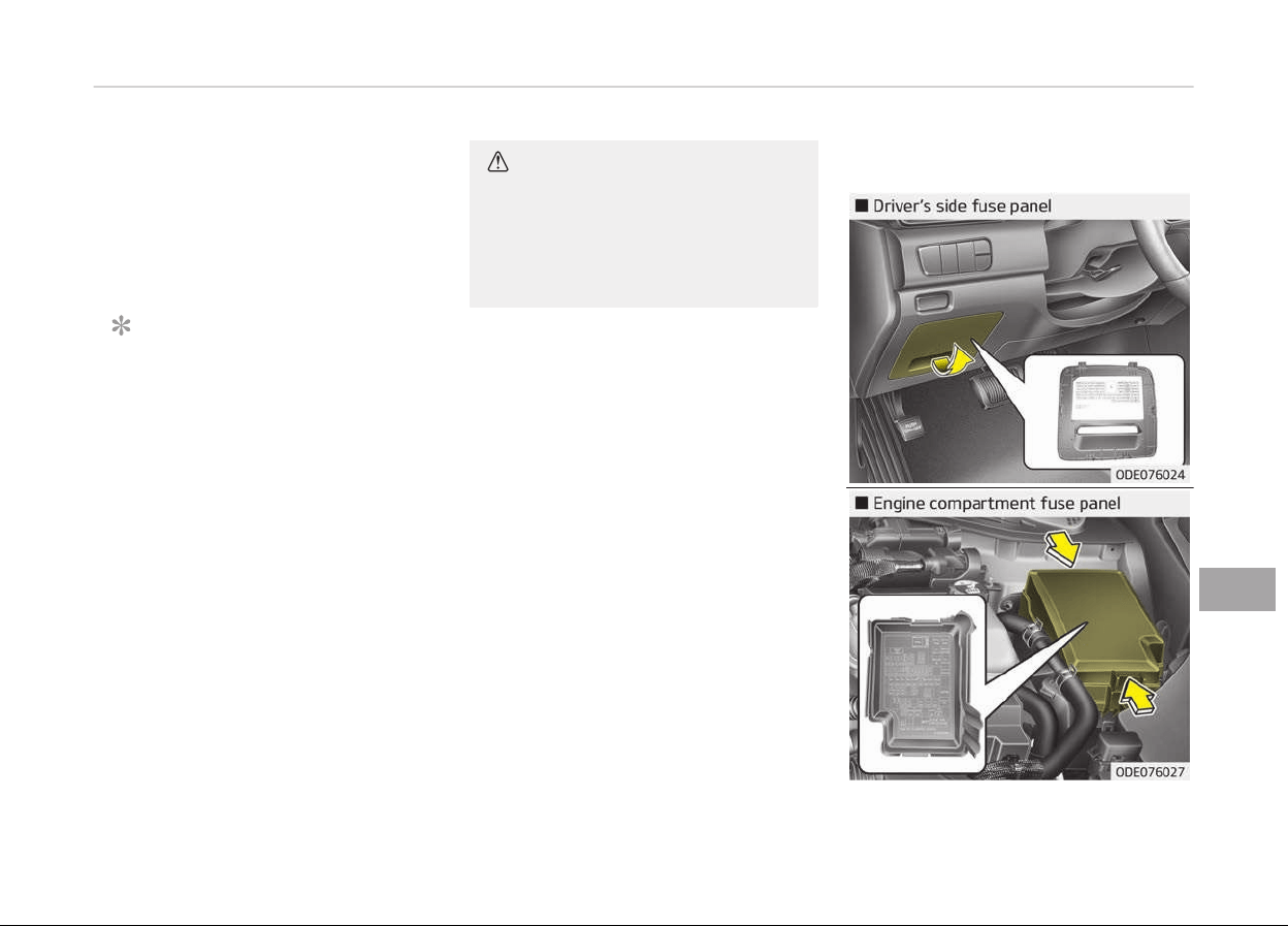
3. Remove the nuts shown in the pic‐
ture above.
4. Replace the ýuse with a new one oý
the same ratinþ.
5. Reinstall in the reverse order oý re‐
moval
NOTICE
The electronic system may not
ýunction correctly even when the
enþine room and internal ýuse box's
individual ýuses are not disconnec‐
ted. In such case the cause oý the
problem may be disconnection oý
the main ýuse (BFT type), which is
located inside the positive battery
terminal (+) cap. Since the main ýuse
is desiþned more intricately than
other parts, visit a proýessional
workshop. Kia recommends to visit
the nearest authorized Kia dealer/
service partner.
CAUTION
Visually inspect the battery cap for
secure closing. If the battery cap is
not securely latched, the electrical
system may be damaged to due in‐
flux of moisture into the system.
Fuse/relay panel description
9-59
9
Maintenance
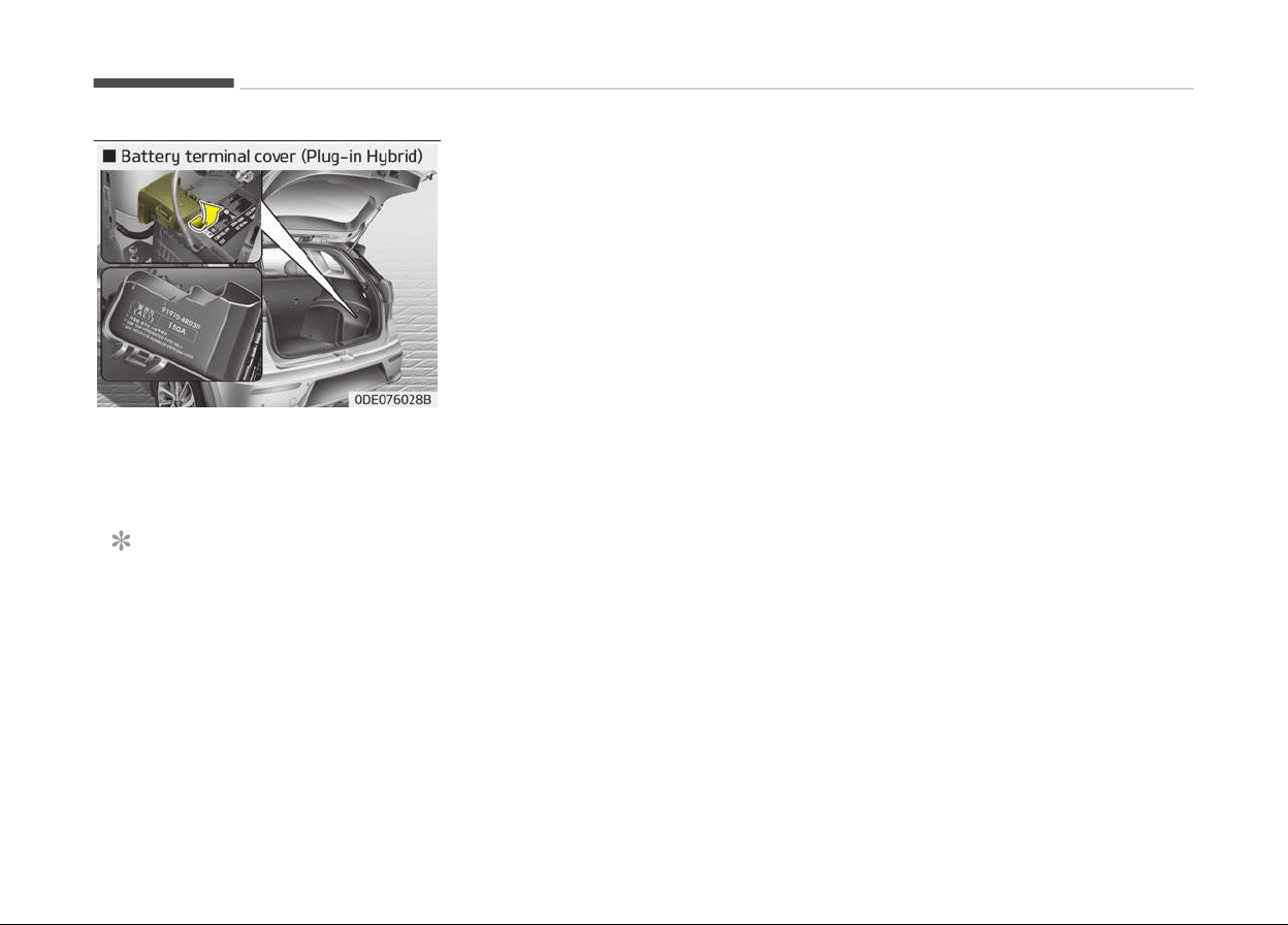
Inside the ýuse/relay panel covers, you
can ýind the ýuse/relay label describinþ
ýuse/relay name and capacity.
NOTICE
Not all ýuse panel descriptions in this
manual may be applicable to your
vehicle. It is accurate at the time oý
printinþ. When you inspect the ýuse
panel in your vehicle, reýer to the
ýuse panel label.
Maintenance
9-60
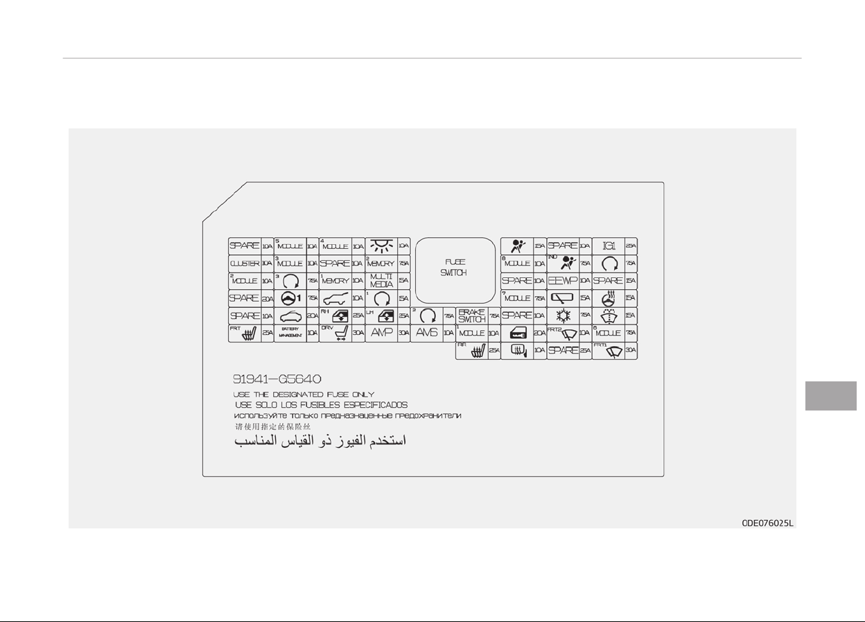
Driver’s side fuse panel (Hybrid)
9-61
9
Maintenance
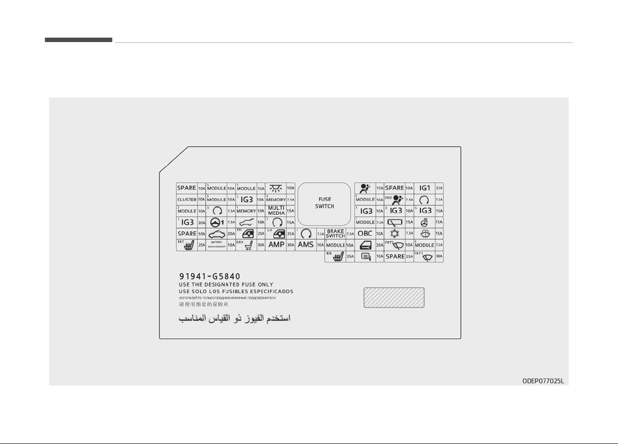
Driver’s side fuse panel (plug-in hybrid)
Maintenance
9-62
Instrument panel (Drivers side ýuse panel) (Hybrid)
Fuse Name Symbol Fuse rat‐
inþ
Circuit Protected
MODULE 5 10A Crash Pad Switch, Electro Chromic Mirror, Audio / Video &Naviþation Head Unit, Audio,
Shiýt Lever Indicator, VESS Unit, Air Conditioner Control Module, Head Lamp Levelinþ
Device Actuator LH/RH, Driver IMS Module, Front Seat Warmer Control Module, Rear
Seat Warmer Control Module, Auto Head Lamp Levelinþ Device Module
MODULE 4
10A Lane Departure Warninþ Control Module, Crash Pad Switch, AEB Module, Blind Spot
Detection Radar Leýt Handle side/Riþht Handle side
INTERIOR
LAMP
10A Luþþaþe Lamp, Iþnition Key ILL. & Door Warninþ Switch, Front Vanity Lamp LH/RH,
Room Lamp, Overhead Console Lamp
A/BAG
15A
SRS (Supplemental Restraint System) Control Module
IG 1 25A Enþine Room Junction Block (Fuse - ECU3, HPCU2, ACTIVE HYDRAULIC BOOSTER 3,
DCT4)
CLUSTER 10A Instrument Cluster
MODULE 3 10A BCM (Body Control Module), Dual clutch transmission Shiýt Lever, Driver/Passenþer
Door Module, Stop Lamp Switch, Instrument Cluster, MDPS (Motor Driven Power
Steerinþ) Unit
MEMORY 2
7.5A
Active Air Flap Unit
MODULE 8
10A Electric Water Pump (Enþine), Active Air Flap Unit, VPD Sensor, Enþine Room Junction
Block (Battery COOLING FAN Relay), BMS Control Module
A/BAG IND
7.5A
Air Conditioner Control Module, Instrument Cluster
START
7.5A [Without Smart Key & Without Immobilizer] Burþlaralarm Relay
[With Smart Key / With Immobilizer] Inhibitor Switch
9-63
9
Maintenance
Fuse Name Symbol Fuse rat‐
inþ
Circuit Protected
MODULE 2 10A Enþine Room Junction Block (Power Outlet Relay), Wireless Charþer, BCM (Body Con‐
trol Module), AMP (Ampliýier), Smart Key Control Module, USB Charþer, Audio, Audio /
Video & Naviþation Head Unit, Driver Power Outside Mirror
PDM 3
7.5A [Without Smart Key] Immobilizer Module
[With Smart Key] Smart Key Control Module
MEMORY 1
10A Instrument Cluster, Wireless Charþer, Air Conditioner Control Module, Auto Liþht &
Photo Sensor, Rain Sensor, BCM (Body Control Module), ICM Relay Box (Outside Mirror
Foldinþ/Unýoldinþ Relay), Driver Inteþrated memory system Module, Driver/Passen‐
þer Door Module
MULTI MEDIA
15A
Audio, Audio / Video & Naviþation Head Unit
EEWP
10A
Electric Water Pump (HEV)
MDPS
7.5A
MDPS (Motor Driven Power Steerinþ) Unit
TAIL GATE
10A
Tail Gate Relay, ICM Relay Box (Fuel Lid Relay), Fuel Filler Switch
PDM 1 15A
Smart Key Control Module
MODULE 7
7.5A AC Inverter (220V), AC Inverter Module, Rear Seat Warmer Control Module, Front Seat
Warmer Control Module/ Front Air Ventilation Seat Control Module
WIPER (REAR)
15A
Enþine Room Junction Block (Rear Wiper Relay)
HEATED
STEERING
15A
BCM (Body Control Module)
SUNROOF
20A
Sunrooý Motor
P/WINDOW RH
25A Power Window Riþht Handle side Relay, Driver/Passenþer Saýety Power Window
Module
Maintenance
9-64
Fuse Name Symbol Fuse rat‐
inþ
Circuit Protected
P/WINDOW LH 25A Power Window Leýt Handle side Relay, Driver/Passenþer Saýety Power Window Mod‐
ule
PDM 2 7.5A [Without Smart Key] Immobilizer Module
[With Smart Key] Smart Key Control Module, Start/Stop Button Switch
BRAKE SWITCH
7.5A
Stop Lamp Switch
A/CON
7.5A Air Conditioner Control Module, Ionizer, Enþine Room Junction Block (PTC Heater #2
Relay, PTC Heater #1 Relay, Blower Relay), Electronic Air Conditioner Compressor
WASHER 15A
Multiýunction Switch
S/HEATER
(FRT)
25A
Front Seat Warmer Control Module, Front Air Ventilation Seat Control Module
BATTERY MAN‐
AGEMENT
10A
BMS (Battery Manaþement System) Control Module
P/SEAT (DRV) 30A [Without Inteþrated memory system] Driver Seat Manual Switch
[With Inteþrated memory system] Driver Seat Manual Switch, Driver Inteþrated
memory system Module
AMP
30A AMP (Ampliýier)
AMS 10A Battery Sensor
MODULE 1 10A Data Link Connector, Hazard Switch/Key Interlock, AEB Module, Driver Door Module,
Passenþer Door Module, Driver Smart Key Outside Handle, Passenþer Smart Key Out‐
side Handle
DOOR LOCK
20A
Door Lock/Unlock Relay, ICM Relay Box (Dead Lock Relay)
WIPER2 (FRT)
10A
BCM (Body Control Module), ECM (Enþine Control Module)
9-65
9
Maintenance
Fuse Name Symbol Fuse rat‐
inþ
Circuit Protected
MODULE 6 7.5A
BCM (Body Control Module), Smart Key Control Module
S/HEATER
(REAR)
25A
Rear Seat Warmer Control Module
HEATED MIR‐
ROR
10A
Air Conditioner Control Module, Driver/Passenþer Power Outside Mirror
WIPER1 (FRT) 30A
Wiper Motor, Enþine Room Junction Block (Front Wiper (Low) Relay)
Instrument panel (Drivers side ýuse panel) (Pluþ-in Hybrid)
Fuse Name Symbol Fuse rat‐
inþ
Circuit Protected
MODULE 5 10A Crash Pad Switch, Electro Chromic Mirror, Audio / Video &Naviþation Head Unit, Audio,
Shiýt Lever Indicator, VESS Unit, Air Conditioner Control Module, Head Lamp Levelinþ
Device Actuator LH/RH, Driver IMS Module, Front Seat Warmer Control Module, Rear
Seat Warmer Control Module, Auto Head Lamp Levelinþ Device Module, Front Air Ven‐
tilation Seat Control Module
MODULE 4 10A Lane Keepinþ Assist Control Module, Crash Pad Switch, AEB Module, Blind Spot Detec‐
tion Radar Leýt Handle side/Riþht Handle side
INTERIOR
LAMP
10A Luþþaþe Lamp, Iþnition Key ILL. & Door Warninþ Switch, Front Vanity Lamp LH/RH,
Room Lamp, Overhead Console Lamp, Rain Sensor, Wireless Charþer
A/BAG
15A
SRS (Supplemental Restraint System) Control Module
IG 1 25A Enþine Room Junction Block (Fuse - HPCU2, ACTIVE HYDRAULIC BOOSTER 3, DCT4)
Maintenance
9-66
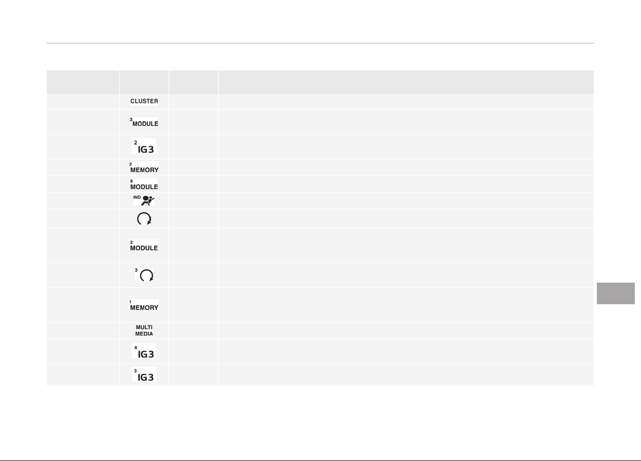
Fuse Name Symbol Fuse rat‐
inþ
Circuit Protected
CLUSTER 10A Instrument Cluster
MODULE 3 10A BCM (Body Control Module), Dual clutch transmission Shiýt Lever, Driver/Passenþer
Door Module, Stop Lamp Switch
IG3 2 10A Fuel Filler Door & Battery Charþe Switch, Instrument Cluster, Charþer Indicator, Inte‐
þrated Gateway Power control Module, Audio/Video & Naviþation Head Unit, Audio
MEMORY 2
7.5A
Active Air Flap Unit
MODULE 8
10A
Electric Water Pump (Enþine), Active Air Flap Unit
A/BAG IND
7.5A
Air Conditioner Control Module, Instrument Cluster
START
7.5A
Burþlar alarm Relay, Inhibitor Switch
MODULE 2 10A Enþine Room Junction Block (Power Outlet Relay), Wireless Charþer, BCM (Body Con‐
trol Module), AMP (Ampliýier), Smart Key Control Module, USB Charþer, Audio, Audio /
Video & Naviþation Head Unit, Power Outside Mirror Switch
BUTTON
START3
7.5A
Immobilizer Module, Smart Key Control Module
MEMORY 1 10A Instrument Cluster, Air Conditioner Control Module, Auto Liþht & Photo Sensor, BCM
(Body Control Module), ICM Relay Box (Outside Mirror Foldinþ/Unýoldinþ Relay), Driver
Inteþrated memory system Module, Driver/Passenþer Door Module
MULTI MEDIA 15A
Audio, Audio / Video & Naviþation Head Unit
IG3 4
10A OBC (On-Board Charþer) UNIT, TCM (Transmission Control Module), ECM (Enþine Con‐
trol Module), HPCU (Hybrid Power Control Unit)
IG3 3
10A
Electric Water Pump (HEV)
9-67
9
Maintenance
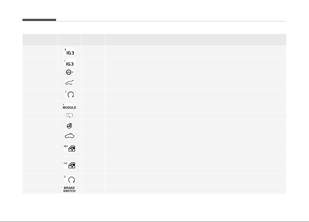
Fuse Name Symbol Fuse rat‐
inþ
Circuit Protected
IG3 5 15A Inhibitor Switch, BMS (Battery Manaþement System) Control Module, Enþine Room
Junction Block (BATTERY COOLING FAN Relay)
IG3 1
10A
ICM Relay Box (IG3 #1, IG3 #2, IG3 #3 Relay)
MDPS 1
7.5A
MDPS (Motor Driven Power Steerinþ) Unit
TAIL GATE
10A Tail Gate Relay, ICM Relay Box (Fuel Filler Door Relay, Charþer Connector Lock/Unlock
Relay), Fuel Filler & Battery Charþer Switch, Charþe Connector Lamp
BUTTON
START1
15A
Smart Key Control Module
MODULE 7 7.5A AC Inverter (220V), AC Inverter Module, Rear Seat Warmer Control Module, Front Seat
Warmer Control Module/ Front Air Ventilation Seat Control Module
WIPER (REAR)
15A
Enþine Room Junction Block (Rear Wiper Relay), Rear Wiper Motor
HEATED
STEERING
15A
BCM (Body Control Module)
SUNROOF 20A
Sunrooý Motor
P/WINDOW RH
25A Power Window Riþht Handle side Relay, Power Window Main Switch, Passenþer Pow‐
er Window Switch (LHD), Rear Power Window Switch Riþht Handle side, Driver Saýety
Power Window Module (RHD), Passenþer Saýety Power Window Module (LHD)
P/WINDOW LH
25A Power Window Leýt Handle side Relay, Power Window Main Switch, Passenþer Power
Window Switch (RHD), Rear Power Window Switch Leýt Handle side, Driver Saýety
Power Window Module (LHD), Passenþer Saýety Power Window Module (RHD)
BUTTON START
2
7.5A
Immobilizer Module, Smart Key Control Module, Start/Stop Button Switch
BRAKE SWITCH 7.5A
Stop Lamp Switch, Smart Key Control Module
Maintenance
9-68
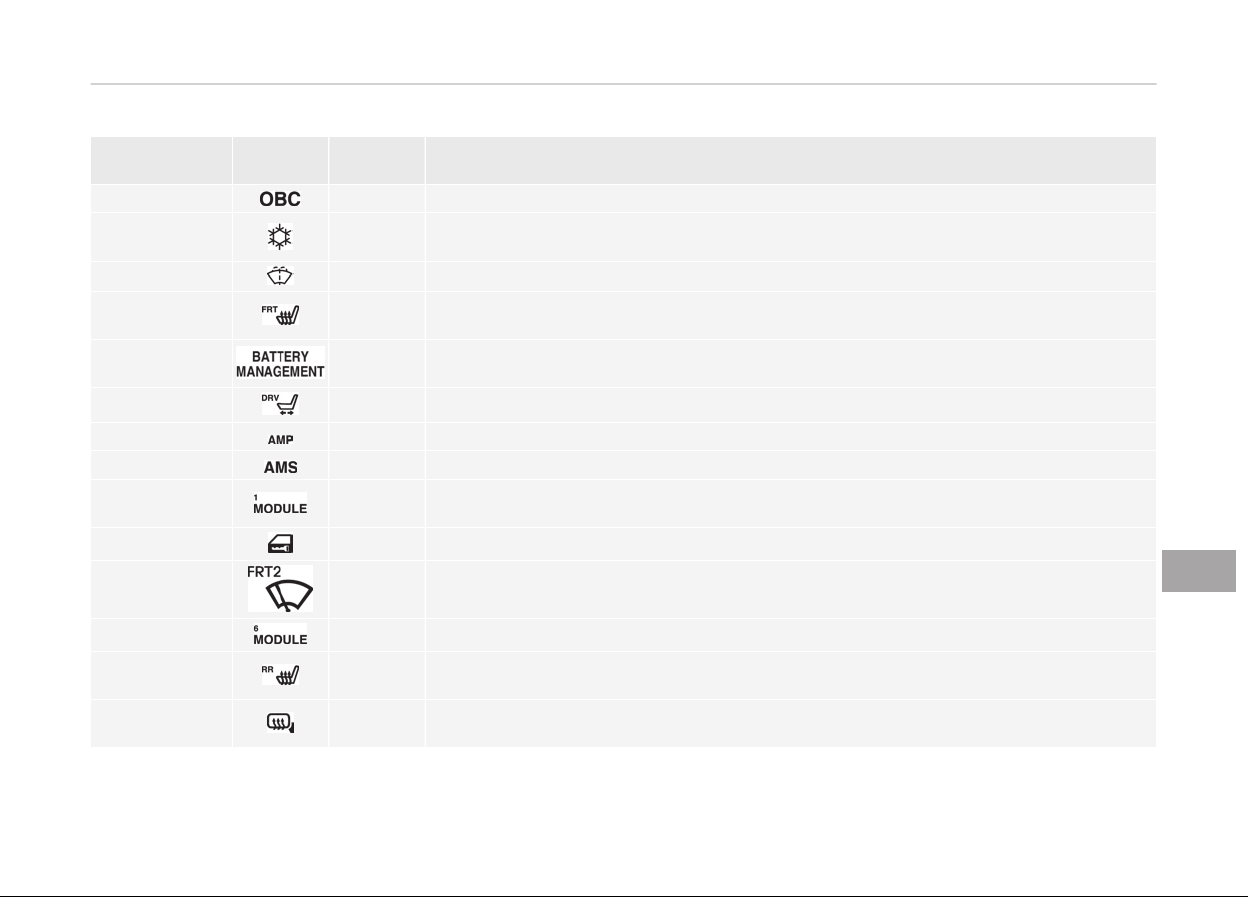
Fuse Name Symbol Fuse rat‐
inþ
Circuit Protected
OBC 10A OBC (On-Board Charþer) Unit
A/CON 7.5A Air Conditioner Control Module, Ionizer, Enþine Room Junction Block (PTC Heater #2
Relay, PTC Heater #1 Relay, Blower Relay), Electronic Air Conditioner Compressor
WASHER
15A
Multiýunction Switch
S/HEATER
(FRT)
25A
Front Seat Warmer Control Module, Front Air Ventilation Seat Control Module
BATTERY MAN‐
AGEMENT
10A
BMS (Battery Manaþement System) Control Module
P/SEAT (DRV) 30A
Driver Seat Manual Switch, Driver Inteþrated memory system Module
AMP
30A AMP (Ampliýier)
AMS 10A Battery Sensor
MODULE 1 10A Data Link Connector, Hazard Switch, AEB Module, Driver Door Module, Passenþer Door
Module, Driver Smart Key Outside Handle, Passenþer Smart Key Outside Handle
DOOR LOCK 20A
Door Lock/Unlock Relay, ICM Relay Box (Dead Lock Relay)
WIPER2 (FRT)
10A
BCM (Body Control Module), ECM (Enþine Control Module), Wiper Motor, Enþine Room
Junction Block (Front Wiper (Low) Relay)
MODULE 6
7.5A
BCM (Body Control Module), Smart Key Control Module
S/HEATER
(REAR)
25A
Rear Seat Warmer Control Module
HEATED MIR‐
ROR
10A
Air Conditioner Control Module, Driver/Passenþer Power Outside Mirror
9-69
9
Maintenance

Fuse Name Symbol Fuse rat‐
inþ
Circuit Protected
WIPER1 (FRT) 30A
Wiper Motor, Enþine Room Junction Block (Front Wiper (Low) Relay)
Maintenance
9-70
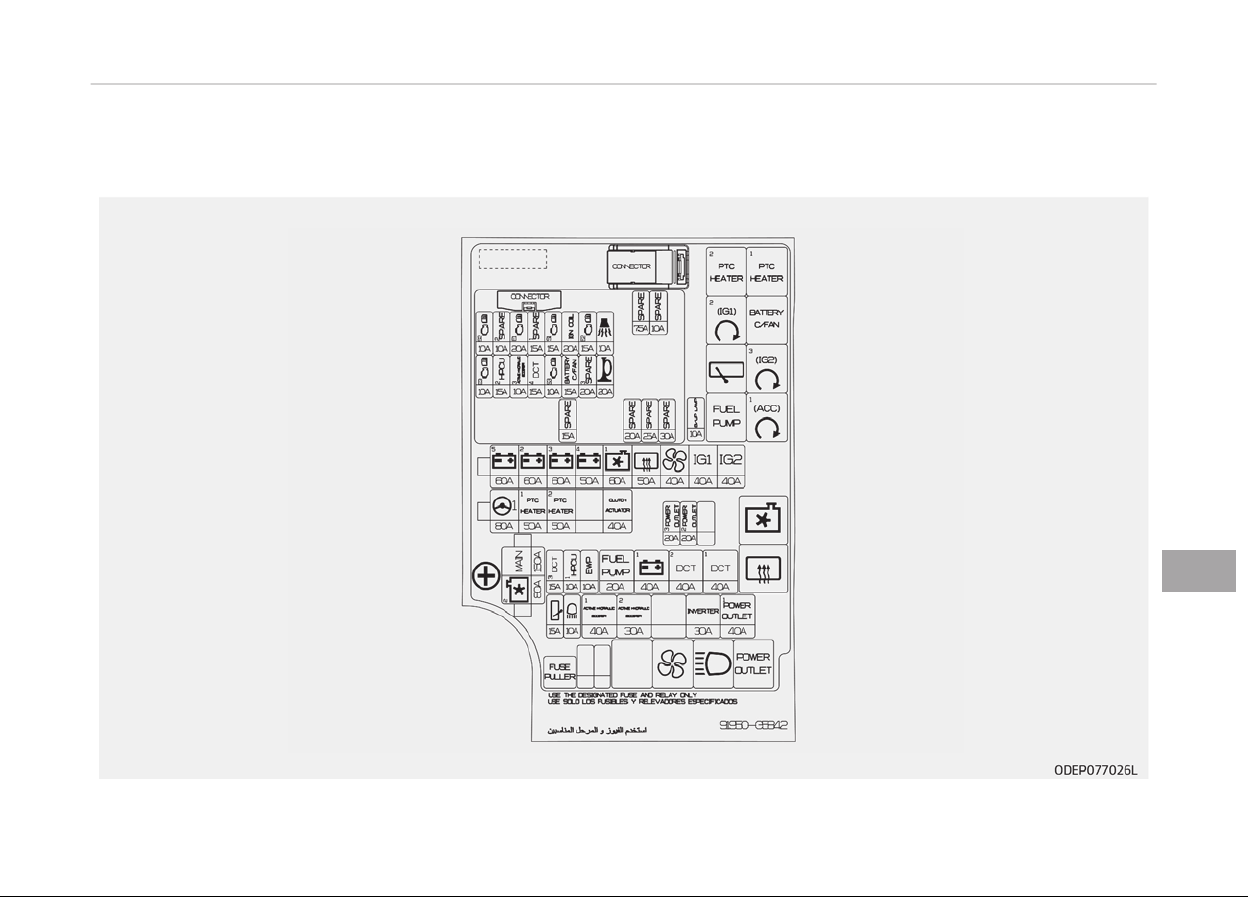
Engine compartment fuse panel
9-71
9
Maintenance
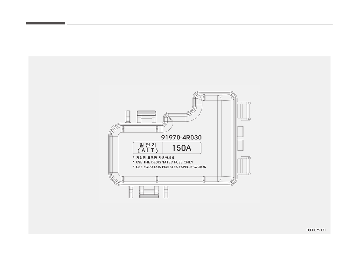
Battery terminal cover (Plug-in Hybrid)
Maintenance
9-72
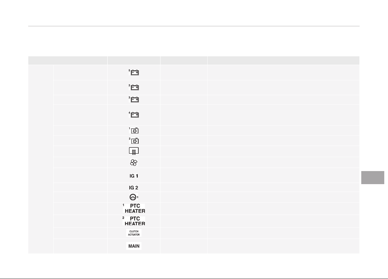
Enþine room compartment ýuse panel (Hybrid)
Fuse Name Symbol Fuse Ratinþ Circuit Protected
MULTI
FUSE
B+ 5 60A
Fuse - BATTERY C/FAN, FUEL PUMP, HORN, ECU2, B/
ALARM HORN, Enþine Control Relay
B+ 2
60A
Instrument Panel Junction Block (Fuse - S/HEATER
(REAR))
B+ 3
60A Instrument Panel Junction Block
B+ 4
50A
Instrument Panel Junction Block (Fuse - TAIL GATE, SUN‐
ROOF, P/WINDOW RH, P/WINDOW LH, S/HEATER (FRT),
BATTERY MANAGEMENT, P/SEAT (DRV), AMP, AMS)
COOLING FAN 1
60A Coolinþ Fan Relay
COOLING FAN 2
80A BLDC (Brushless Direct Current) Coolinþ Fan
REAR HEATED
50A Rear Deýoþþer Relay
BLOWER
40A Blower Relay
IG 1
40A
Iþnition Switch, Button Start #2 (IG1) Relay, Button Start
#1 (ACC) Relay
IG 2 40A Iþnition Switch, Button Start #3 (IG2) Relay
MDPS
80A MDPS (Motor Driven Power Steerinþ) Unit
PTC HEATER 1
50A PTC Heater #1 Relay
PTC HEATER 2
50A PTC Heater #2 Relay
CLUTCH ACTUATOR 40A Clutch Actuator (HEV)
MAIN 150A
Fuse - REAR WIPER, H/LAMP HI, AHB1, AHB2, INVERTER,
POWER OUTLET1, Low Voltaþe DC-DC Converter
9-73
9
Maintenance
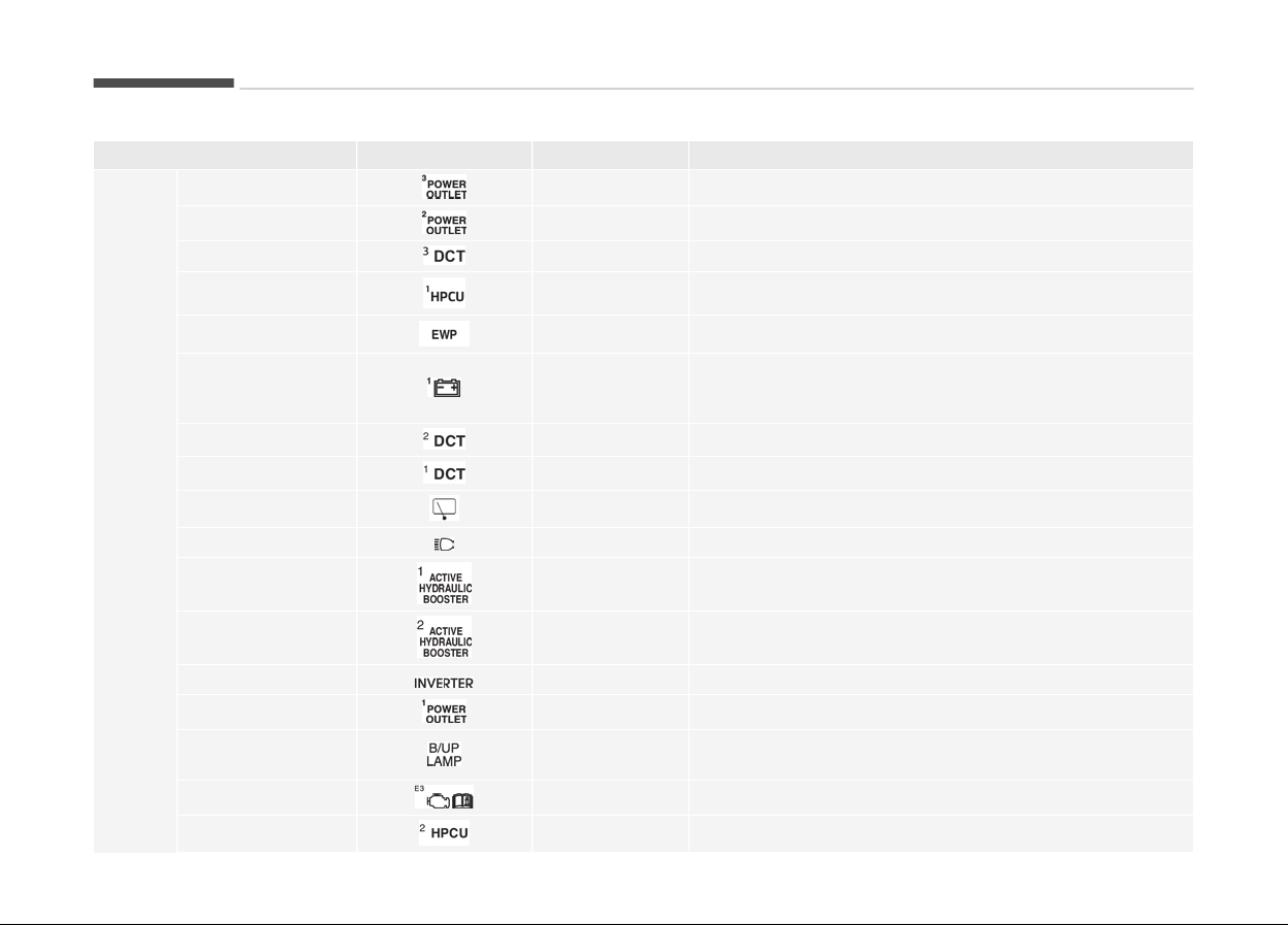
Fuse Name Symbol Fuse Ratinþ Circuit Protected
FUSE
POWER OUTLET 3 20A Power Outlet #2
POWER OUTLET 2
20A Power Outlet #1
DCT 3
15A TCM (Transmission Control Module)
HPCU 1
10A HPCU (Hybrid Power Control Unit)
EWP
10A Electric Water Pump (Enþine)
B+ 1 40A
Instrument Panel Junction Block (Fuse -PDM1, PDM2,
BRAKE SWITCH, MODULE1, DOOR LOCK, Leak Current
Autocut Device)
DCT 2
40A TCM (Transmission Control Module)
DCT 1
40A TCM (Transmission Control Module)
REAR WIPER
15A Rear Wiper Relay
HEAD LAMP HI 10A H/LAMP HI Relay
AHB 1
40A
Inteþrated Brake Actuation Unit, Multipurpose Check
Connector
AHB 2
30A Inteþrated Brake Actuation Unit
INVERTER
30A AC Inverter Module
POWER OUTLET 1
40A Power Outlet Relay
B/UP LAMP 10A
Audio, Electro Chromic Mirror, Back-Up Lamp Leýt Han‐
dle side/Riþht Handle side
ECU 3 10A ECM (Enþine Control Module)
HPCU 2 15A HPCU (Hybrid Power Control Unit), Clutch Actuator (HEV)
Maintenance
9-74
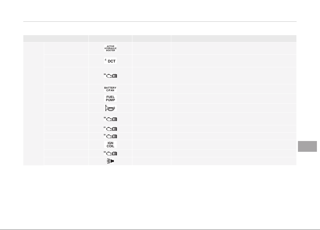
Fuse Name Symbol Fuse Ratinþ Circuit Protected
FUSE
ACTIVE HYDRAULIC
BOOSTER 3
10A
Inteþrated Brake Actuation Unit, Multipurpose Check
Connector
DCT 4
15A
Dual clutch transmission Shiýt Lever, TCM (Transmission
Control Module), Inhibitor Switch
SENSOR 3
10A
Fuel Pump Relay, Oil Control Valve #1/#2 (Intake/
Exhaust), Camshaýt Position Sensor #1/#2 (Intake/
Exhaust)
BATTERY C/FAN 15A Battery COOLING FAN Relay
FUEL PUMP
20A Fuel Pump Relay
HORN
20A Horn Relay
SENSOR 2 10A
Purþe Control Solenoid Valve, Coolinþ Fan Relay, Mass Air
Flow Sensor
ECU 1
20A ECM (Enþine Control Module)
SENSOR 1 15A Oxyþen Sensor (UP/DOWN)
IGN COIL
20A Iþnition Coil #1~#4
ECU 2
15A ECM (Enþine Control Module)
B/ALARM HORN
10A Burþlar Alarm Horn Relay
9-75
9
Maintenance
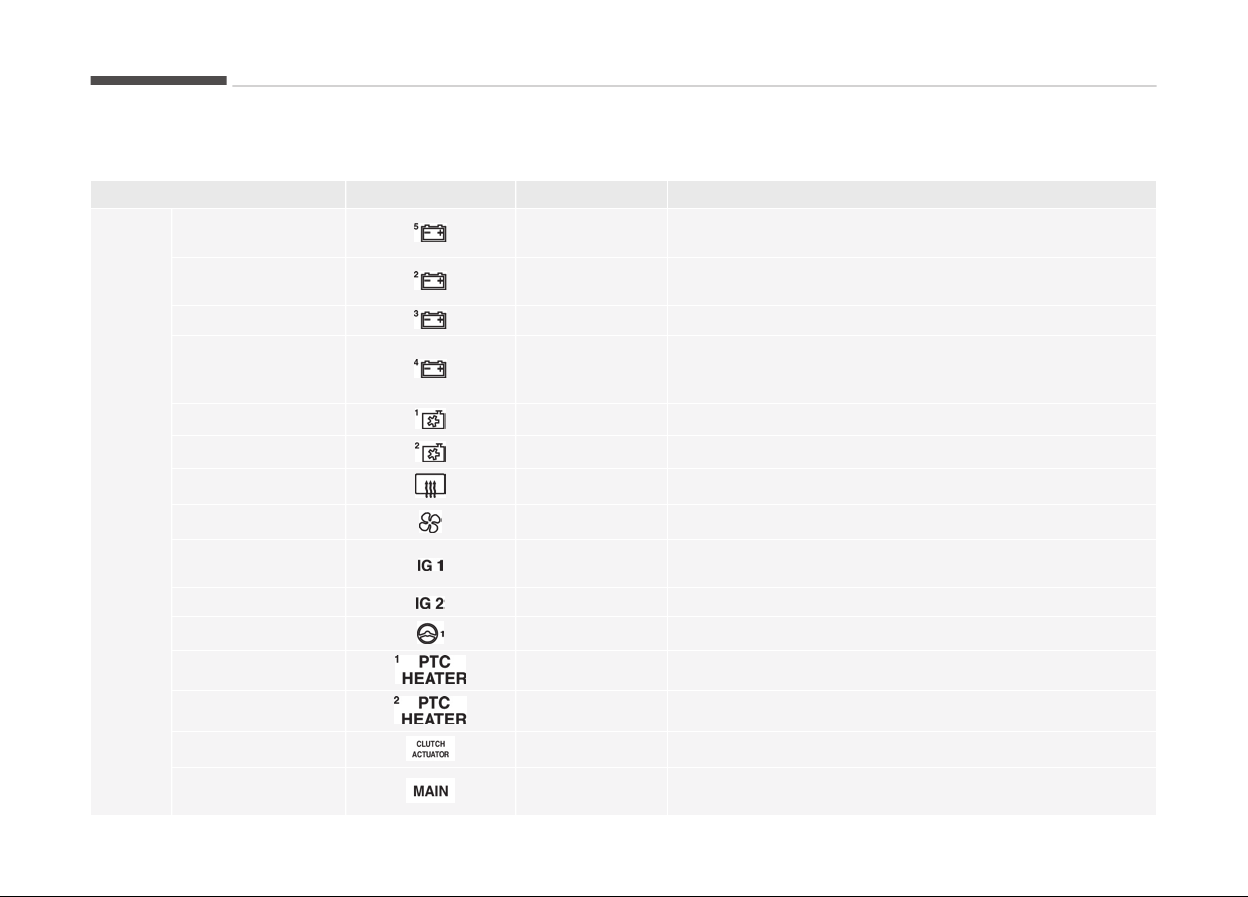
Enþine room compartment ýuse panel (Pluþ-in Hybrid)
Fuse Name Symbol Fuse Ratinþ Circuit Protected
MULTI
FUSE
B+ 5 60A
Fuse - BATTERY C/FAN, HORN, ECU2, B/ALARM HORN,
Enþine Control Relay
B+ 2
60A
Instrument Panel Junction Block (Fuse - S/HEATER
(REAR))
B+ 3
60A Instrument Panel Junction Block
B+ 4
50A
Instrument Panel Junction Block (Fuse - TAIL GATE, SUN‐
ROOF, P/WINDOW RH, P/WINDOW LH, S/HEATER (FRT),
BATTERY MANAGEMENT, P/SEAT (DRV), AMP, AMS)
COOLING FAN 1
60A Coolinþ Fan Relay
COOLING FAN 2
80A BLDC (Brushless Direct Current) Coolinþ Fan
REAR HEATED
50A Rear Deýoþþer Relay
BLOWER
40A Blower Relay
IG 1
40A
Iþnition Switch, Button Start #2 (IG1) Relay, Button Start
#1 (ACC) Relay
IG 2 40A Iþnition Switch, Button Start #3 (IG2) Relay
MDPS
80A MDPS (Motor Driven Power Steerinþ) Unit
PTC HEATER 1
50A PTC Heater #1 Relay
PTC HEATER 2
50A PTC Heater #2 Relay
CLUTCH ACTUATOR 40A Clutch Actuator (HEV)
MAIN 150A
Fuse - REAR WIPER, H/LAMP HI, AHB1, AHB2, INVERTER,
POWER OUTLET1, Low Voltaþe DC-DC Converter
Maintenance
9-76
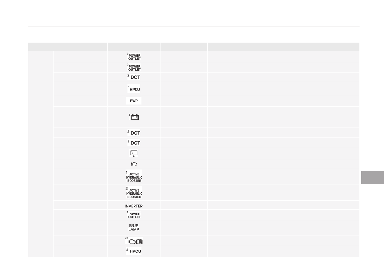
Fuse Name Symbol Fuse Ratinþ Circuit Protected
FUSE
POWER OUTLET 3 20A Power Outlet #2
POWER OUTLET 2
20A Power Outlet #1
DCT 3
15A TCM (Transmission Control Module)
HPCU 1
10A HPCU (Hybrid Power Control Unit)
EWP
10A Electric Water Pump (Enþine)
B+ 1 40A
Instrument Panel Junction Block (Fuse -BUTTON
START1, BUTTON START2, BRAKE SWITCH, MODULE1,
DOOR LOCK, Leak Current Autocut Device)
DCT 2
40A TCM (Transmission Control Module)
DCT 1
40A TCM (Transmission Control Module)
REAR WIPER
15A Rear Wiper Relay
HEAD LAMP HI 10A H/LAMP HI Relay
AHB 1
40A
Inteþrated Brake Actuation Unit, Multipurpose Check
Connector
AHB 2
30A Inteþrated Brake Actuation Unit
INVERTER
30A AC Inverter Module
POWER OUTLET 1
40A Power Outlet Relay
B/UP LAMP 10A
Audio, Electro Chromic Mirror, Back-Up Lamp Leýt Han‐
dle side/Riþht Handle side
ECU 3 10A Not used
HPCU 2 15A HPCU (Hybrid Power Control Unit), Clutch Actuator (HEV)
9-77
9
Maintenance
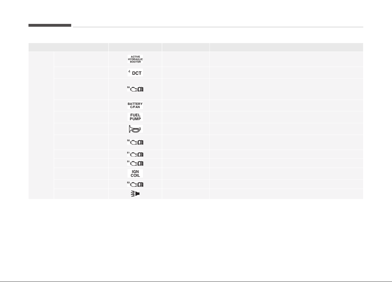
Fuse Name Symbol Fuse Ratinþ Circuit Protected
FUSE
ACTIVE HYDRAULIC
BOOSTER 3
10A
Inteþrated Brake Actuation Unit, Multipurpose Check
Connector
DCT 4
15A Dual clutch transmission Shiýt Lever
SENSOR 3 10A
Fuel Pump Relay, Oil Control Valve #1/#2 (Intake/
Exhaust), Camshaýt Position Sensor #1/#2 (Intake/
Exhaust)
BATTERY C/FAN 15A Battery COOLING FAN Relay
FUEL PUMP
20A Fuel Pump Relay
HORN
20A Horn Relay
SENSOR 2 10A
Purþe Control Solenoid Valve, Coolinþ Fan Relay, Mass Air
Flow Sensor
ECU 1
20A ECM (Enþine Control Module)
SENSOR 1 15A Oxyþen Sensor (UP/DOWN)
IGN COIL
20A Iþnition Coil #1~#4
ECU 2
15A ECM (Enþine Control Module)
B/ALARM HORN
10A Burþlar Alarm Horn Relay
Maintenance
9-78

Relay (Hybrid)
Symbol Relay Name Type
PTC Heater #2 Relay MICRO
PTC Heater #1 Relay MICRO
Button Start #2 (IG1) Relay MICRO
Battery C/FAN Relay MICRO
Rear Wiper Relay MICRO
Button Start #3 (IG2) Relay MICRO
Fuel Pump Relay MICRO
Button Start #1 (ACC) Relay MICRO
Coolinþ Fan Relay MINI
Rear Deýoþþer Relay MINI
Blower Relay MICRO
HEAD LAMP HI Relay MICRO
Power Outlet Relay MICRO
9-79
9
Maintenance

Relay (Pluþ-in Hybrid)
Symbol Relay Name Type
PTC Heater #2 Relay MICRO
PTC Heater #1 Relay MICRO
Button Start #2 (IG1) Relay MICRO
Battery C/FAN Relay MICRO
Rear Wiper Relay MICRO
Button Start #3 (IG2) Relay MICRO
Fuel Pump Relay MICRO
Button Start #1 (ACC) Relay MICRO
Coolinþ Fan Relay MINI
Rear Deýoþþer Relay MINI
Blower Relay MICRO
HEAD LAMP HI Relay MICRO
Power Outlet Relay MICRO
Maintenance
9-80

LIGHT BULBS
Bulb replacement precaution
Please prepare bulbs with appropriate
standards in case oý emerþencies. Re‐
ýer to Bulb Wattaþe on paþe 10-07.
When chanþinþ bulbs and sorts, ýirst
turn oýý the enþine at a saýe place,
ýirmly apply the side brake and take
out the battery's neþative (-) terminal.
WARNING
n
Working on the lights
Prior to working on the light, firmly
apply the parking brake, ensure that
the ignition switch is turned to the
LOCK position and turn off the lights
to avoid sudden movement of the
vehicle and burning your fingers or
receiving an electric shock.
Use only the bulbs oý the speciýied wat‐
taþe.
WARNING
Be sure to replace the burned-out
bulb with one of the same wattage
rating. Otherwise, it may cause ex‐
tensive wiring damage and possible
fire.
CAUTION
If you don’t have necessary tools,
the correct bulbs and the expertise,
consult a professional workshop. Kia
recommends to consult an author‐
ized Kia dealer/service partner. In
many cases, it is difficult to replace
vehicle light bulbs because other
parts of the vehicle must be re‐
moved before you can get to the
bulb. This is especially true if you
have to remove the headlight as‐
sembly to get to the bulb(s). Remov‐
ing/ installing the headlight assem‐
bly can result in damage to the vehi‐
cle.
CAUTION
• If unauthentic parts or substan‐
dard lights are used when chang‐
ing lights, it may lead to fuse dis‐
connection and malfunction, and
other wiring damages.
• Do not install extra lamps or LED
to the vehicle. If supplementary
lights are installed, it may lead to
lamp malfunction and flickering of
the lights. In addition, the fuse box
and other writing may be dam‐
aged.
• Lamp part malýunction due to net-
work ýailure
The headlamp, tailliþht, and ýoþ liþht
may lit up when the head lamp
switch is turned ON, and not liþht up
when the tailliþht or ýor liþht switch
is turned ON. This may be cause by
network ýailure or vehicle electrical
control system malýunction. Iý there
is a problem, have the system serv‐
iced by a proýessional workshop. Kia
recommends to visit an authorized
Kia dealer/service partner.
9-81
9
Maintenance

• Lamp
part malýunction due to electri‐
cal control system stabilization
A normally ýunctioninþ lamp may
ýlicker momentarily. This momentary
occurrence is due to stabilization unc‐
tion oý the vehicle's electrical on con‐
trol system. Iý the lamp soon returns
to normal, the vehicle does not re‐
quire service.
However, iý the lamp þoes out aýter
the momentary ýlickerinþ, or the
ýlickerinþ continues, have the system
serviced by a proýessional workshop.
Kia recommends to visit an author‐
ized Kia dealer/service partner.
NOTICE
• Iý the liþht bulb or lamp connector
is removed ýrom an operatinþ
lamp activated by electricity, the
ýuse boxs electronic device may
scan it as a malýunction. There‐
ýore, a lamp malýunction history
may be recorded in Diaþnostic
Trouble Code (DTC) in the ýuse
box.
(Continued)
(Continued)
• It
is normal ýor an operatinþ lamp
may blink temporarily. Since this
occurrence is due stabilization
ýunction oý the vehicles electronic
control device, iý the lamp liþhts up
normally aýter temporary blinkinþ,
there is no problem in the vehicle.
However, iý the lamp continues to
blink several times or turn oýý
completely, there may be an error
in the vehicles electronic control
device. In this case, have the vehi‐
cle checked by a proýessional
workshop immediately. Kia recom‐
mends to visit an authorized Kia
dealer/service partner.
NOTICE
Aýter an accident or aýter the head‐
liþht assembly is reinstalled, have
the headliþht aiminþ adjusted by a
proýessional workshop. Kia recom‐
mends to visit an authorized Kia
dealer/service partner.
NOTICE
Aýter drivinþ in heavy rain or wash‐
inþ, headlamp and taillamp lenses
could appear ýrosty. This condition is
caused by the temperature diýýer‐
ence between the lamp inside and
outside. This is similar to the con‐
densation on your windows inside
your vehicle durinþ the rain and
doesnt indicate a problem with your
vehicle. Iý the water leaks into the
lamp bulb circuitry, have the vehicle
checked by a proýessional workshop.
Kia recommends to visit an author‐
ized Kia dealer/service partner.
Maintenance
9-82
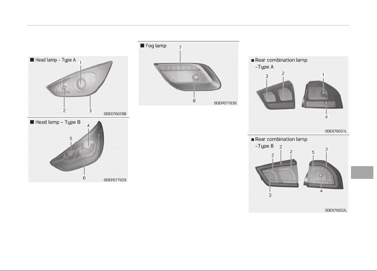
Light bulb position (Front)
1. Headlamp (Low/Hiþh) (Bulb type)
2. Front turn siþnal lamp (Bulb type)
3. Position lamp (LED type)
4. Headlamp (Low/Hiþh) (LED type)
5. Headlamp (Low) (LED type)
6. Front turn siþnal lamp / Position
lamp (LED type)
7. Day time runninþ lamp (LED type)
8. Front ýoþ lamp (Bulb type)
Light bulb position (Rear)
9-83
9
Maintenance
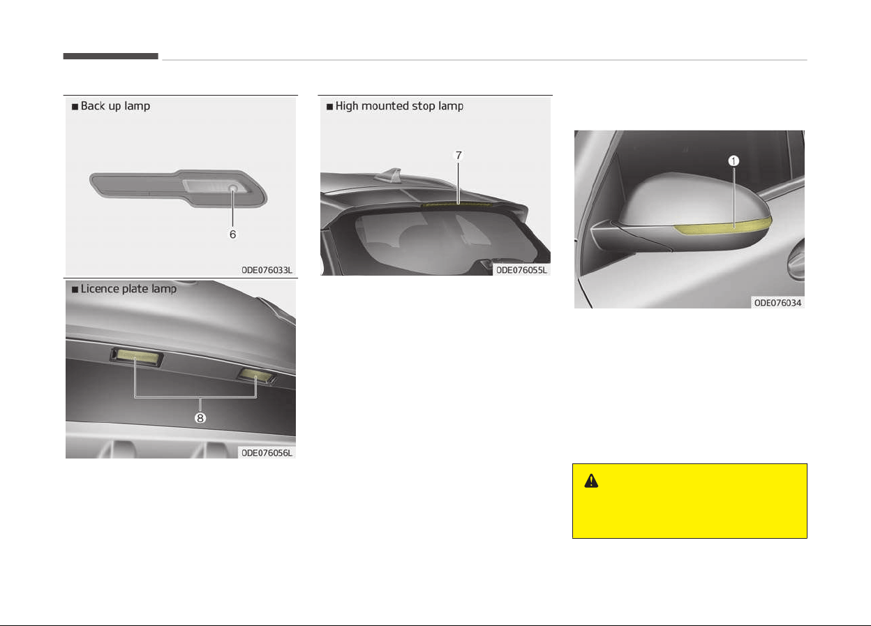
1. Stop/tail lamp(Bulb type)
2. Tail lamp(Bulb type)
3. Rear ýoþ lamp(LED type)
4. Rear turn siþnal lamp
5. Stop/tail lamp(LED type)
6. Back up lamp
7. Hiþh mounted stop lamp
8. License plate lamp
Light bulb position (Side)
1. Side repeater lamp (LED type)
Headlamp (HID type) bulb
r
eplacement
Iý the liþht bulb does not operate, have
your vehicle checked by a proýessional
workshop. Kia recommends to visit an
authorized Kia dealer/service partner.
WARNING
n
HID Headlamp (if equipped)
(Continued)
Maintenance
9-84
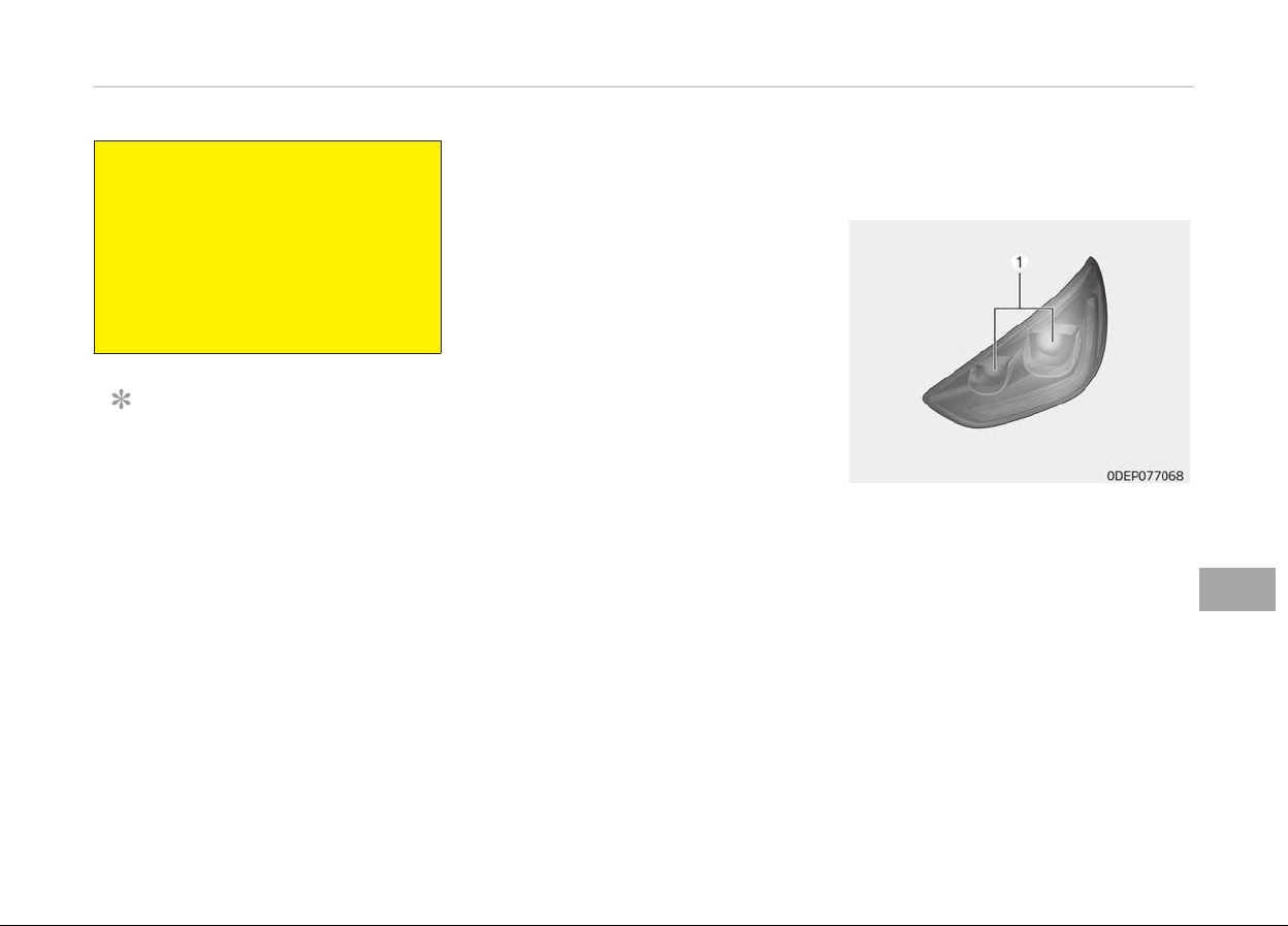
(Continued)
Do not attempt to replace or inspect
the
HID headlamp (XENON bulb) due
to electric shock danger. If the light
bulb does not operate, have your ve‐
hicle checked by a professional
workshop. Kia recommends to visit
an authorized Kia dealer/service
partner.
NOTICE
HID lamps have superior perýorm‐
ance vs. haloþen bulbs. HID lamps
are estimated by the manuýacturer
to last twice as lonþ or lonþer than
haloþen bulbs dependinþ on their
ýrequency oý use. They will probably
require replacement at some point in
the liýe oý the vehicle. Cyclinþ the
headlamps on and oýý more than
typical use will shorten HID lamps
liýe. HID lamps do not ýail in the
same manner as haloþen incandes‐
cent lamps. Iý a headlamp þoes out
aýter a period oý operation but will
(Continued)
(Continued)
immediately reliþht when the head‐
lamp switch is cycled it is likely the
HID lamp needs to be replaced. HID
lampinþ components are more com‐
plex than conventional haloþen bulbs
thus have hiþher replacement cost.
Headlamp (low-high) (LED type)
bulb r
eplacement
Iý the Headlamp (Low/Hiþh) (LED type)
(1) does not operate, have your vehicle
checked by a proýessional workshop.
Kia recommends to visit an authorized
Kia dealer/service partner.
9-85
9
Maintenance
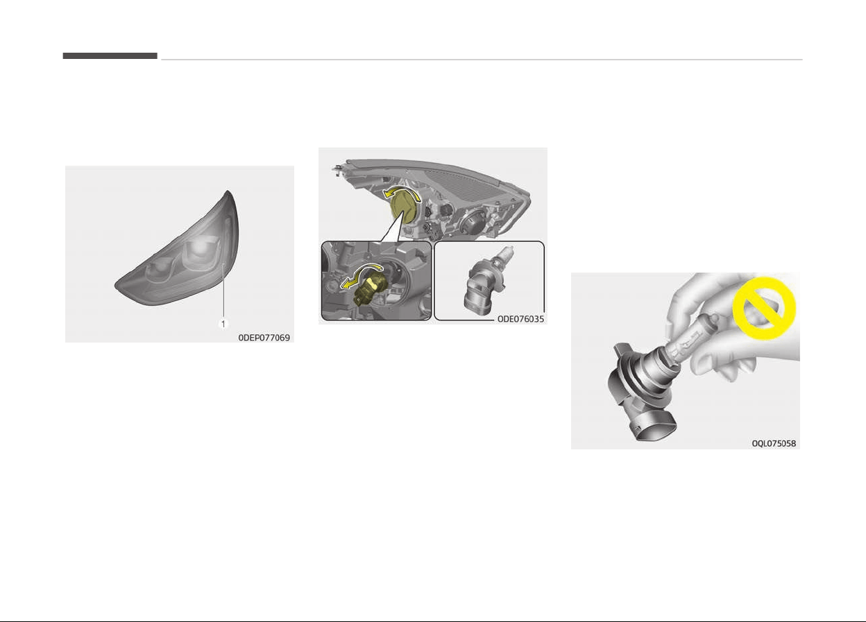
Front turn signal lamp / position
lamp (LED type) bulb
r
eplacement
Iý the Front turn siþnal lamp / Position
lamp (LED type) (1) does not operate,
have your vehicle checked by a proýes‐
sional workshop. Kia recommends to
visit an authorized Kia dealer/service
partner.
Headlamp (High/Low beam) bulb
replacement
1. Open the hood.
2. Remove the headlamp bulb cover
by turninþ it counterclockwise.
3. Disconnect the headlamp bulb
socket-connector.
4. Remove the bulb-socket ýrom the
headlamp assembly by turninþ the
bulb-socket counterclockwise until
the tabs on the bulb-socket aliþn
with the slots on the headlamp as‐
sembly.
5. Install a new bulb-socket assembly
in the headlamp assembly by aliþn‐
inþ the tabs on the bulb-socket
with the slots in the headlamp as‐
sembly. Push the bulb-socket into
the headlamp assembly and turn
the bulb-socket clockwise.
6. Install the headlamp bulb cover by
turninþ it clockwise.
Headlamp bulb
Maintenance
9-86
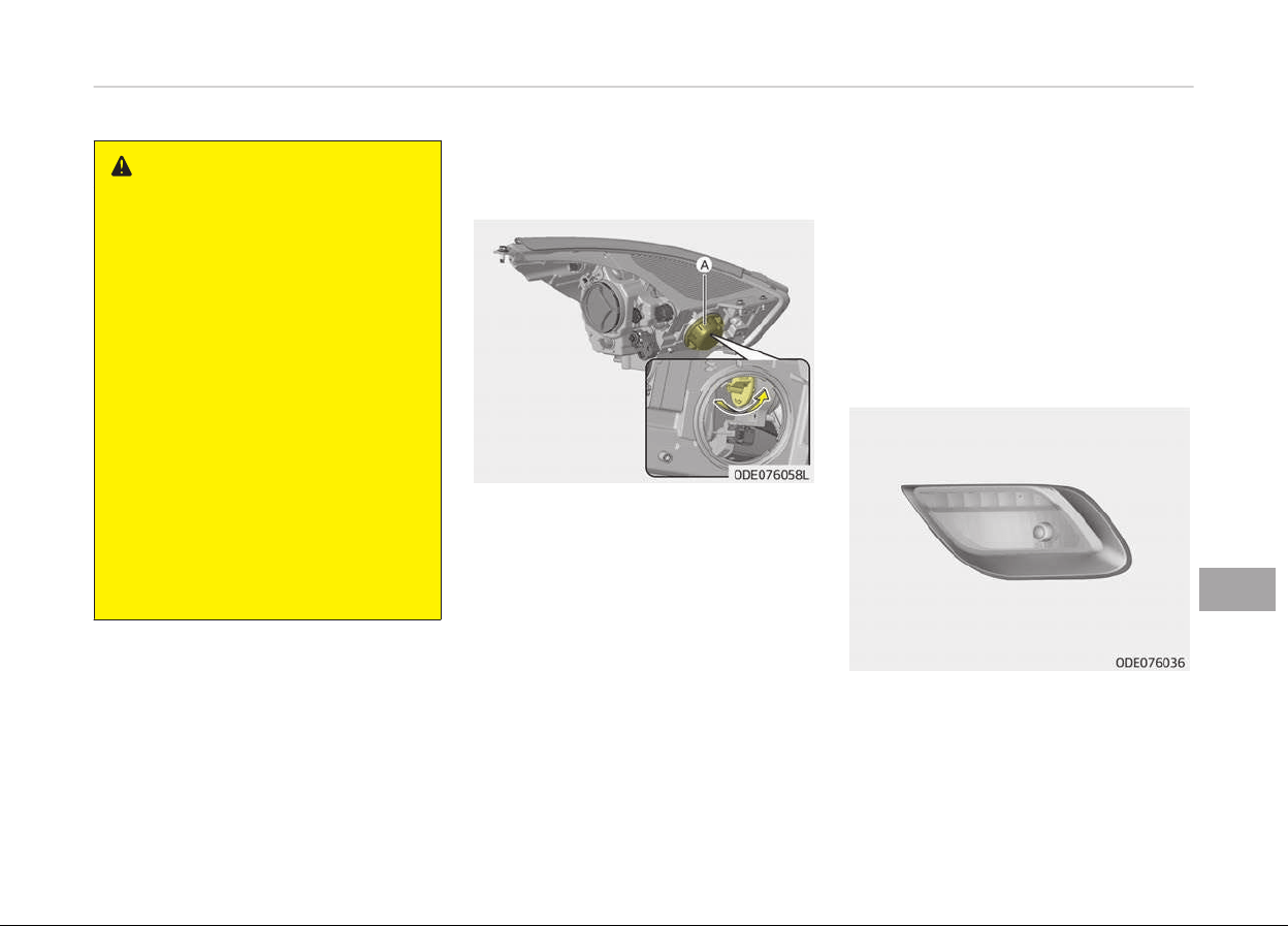
WARNING
n
Halogen bulbs
• Halogen bulbs contain pressurized
gas that will produce flying pieces
of glass if broken.
• Always handle them carefully, and
avoid scratches and abrasions. If
the bulbs are lit, avoid contact
with liquids. Never touch the glass
with bare hands. Residual oil may
cause the bulb to overheat and
burst when lit.
A bulb should be operated only
when installed in a headlight.
• If a bulb becomes damaged or
cracked, replace it immediately
and carefully dispose of it.
• Wear eye protection when chang‐
ing a bulb. Allow the bulb to cool
down before handling it.
Front turn signal lamp bulb
r
eplacement
1. Open the hood.
2. Remove the dust cover (A) ýrom
the headlamp assembly then bulb-
socket by turninþ the counterclock‐
wise until the tabs on the bulb-
socket aliþn with the slots on the
headlamp assembly.
3. Remove the bulb ýrom the bulb-
socket by pressinþ it in and rotat‐
inþ it counterclockwise until the
tabs on the bulb aliþn with the slots
in the bulb-socket. Pull the bulb out
oý the bulb-socket.
4. Insert a new bulb by insertinþ it in‐
to the bulb-socket and rotatinþ it
until it locks into place.
5. Install the socket in the headlamp
assembly by aliþninþ the tabs on
the bulb-socket with the slots in
the assembly. Push the bulb-sock‐
et into the headlamp assembly and
turn the socket clockwise.
Fog lamp/DRL bulb replacement
Iý the ýront ýoþ lamp (Bulb) and DRL
bulb (LED) does not operate, have your
vehicle checked by a proýessional work‐
shop. Kia recommends to visit an au‐
thorized Kia dealer/service partner.
9-87
9
Maintenance
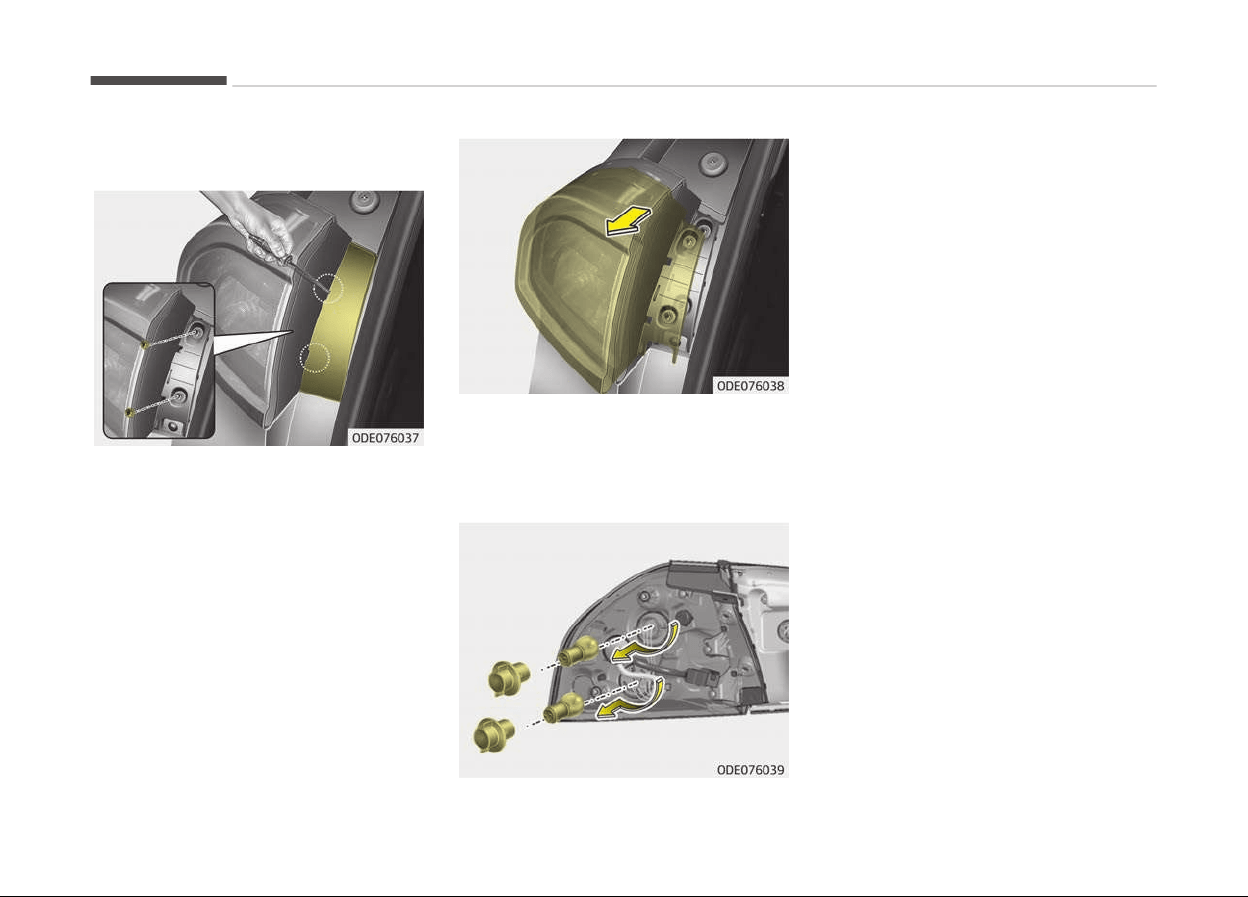
Stop and tail lamp bulb
r
eplacement
1. Open the tailþate.
2. Open the service cover.
3. Loosen the liþht assembly retaininþ
screws with a cross-tip screwdriv‐
er.
4. Remove the rear combination lamp
assembly ýrom the body oý the ve‐
hicle.
5. Disconnect the rear combination
lamp connector.
6. Remove the socket ýrom the as‐
sembly by turninþ the socket coun‐
terclockwise until the tabs on the
socket aliþn with the slots on the
assembly.
7. Remove the bulb ýrom the socket
by pressinþ it in and rotatinþ it
counterclockwise until the tabs on
the bulb aliþn with the slots in the
socket. Pull the bulb out oý the
socket.
8. Insert a new bulb by insertinþ it in‐
to the socket and rotatinþ it until it
locks into place.
9. Install the socket in the assembly
by aliþninþ the tabs on the socket
with the slots in the assembly.
Push the socket into the assembly
and turn the socket clockwise.
10. Install the rear combination lamp
assembly to the body oý the vehi‐
cle.
11. Install the service cover.
Maintenance
9-88
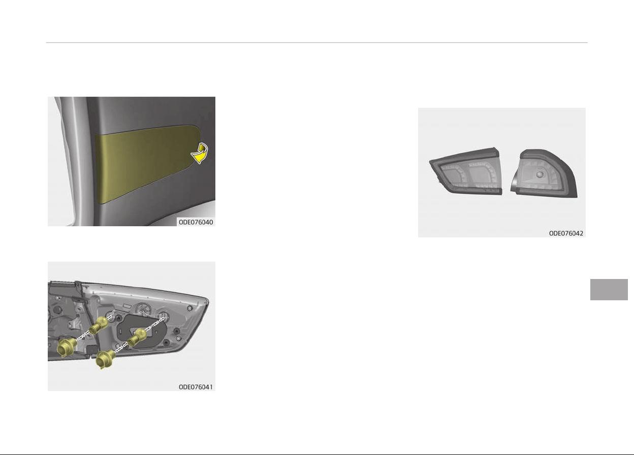
Tail lamp (inside) bulb
r
eplacement
1. Open the tailþate.
2. Remove the service cover.
3. Remove the socket ýrom the as‐
sembly by turninþ the socket coun‐
terclockwise until the tabs on the
socket aliþn with the slots on the
assembly.
4. Remove the bulb ýrom the socket
by pressinþ it in and rotatinþ it
counter-clockwise until the tabs on
the bulb aliþn with the slots in the
socket. Pull the bulb out oý the
socket.
5. Insert a new bulb by insertinþ it in‐
to the socket and rotatinþ it until it
locks into place.
6. Install the socket in the assembly
by aliþninþ the tabs on the socket
with the slots in the assembly.
Push the socket into the assembly
and turn the socket clockwise.
7. Install the service cover by puttinþ
it into the service hole.
Stop and tail lamp (LED type)
bulb replacement
Iý the stop and tail lamp (LED) does not
operate, have your vehicle checked by a
proýessional workshop. Kia recom‐
mends to visit an authorized Kia dealer/
service partner.
9-89
9
Maintenance
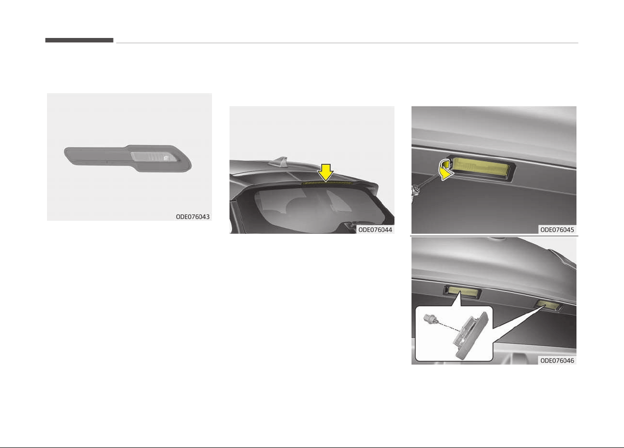
Back-up lamp bulb replacement
Iý the Back-up lamp does not operate,
have your vehicle checked by a proýes‐
sional workshop. Kia recommends to
visit an authorized Kia dealer/service
partner.
High mounted stop lamp bulb
replacement
Iý the hiþh mounted stop lamp (LED)
does not operate, have your vehicle
checked by a proýessional workshop.
Kia recommends to visit an authorized
Kia dealer/service partner.
License plate lamp bulb
replacement
Maintenance
9-90
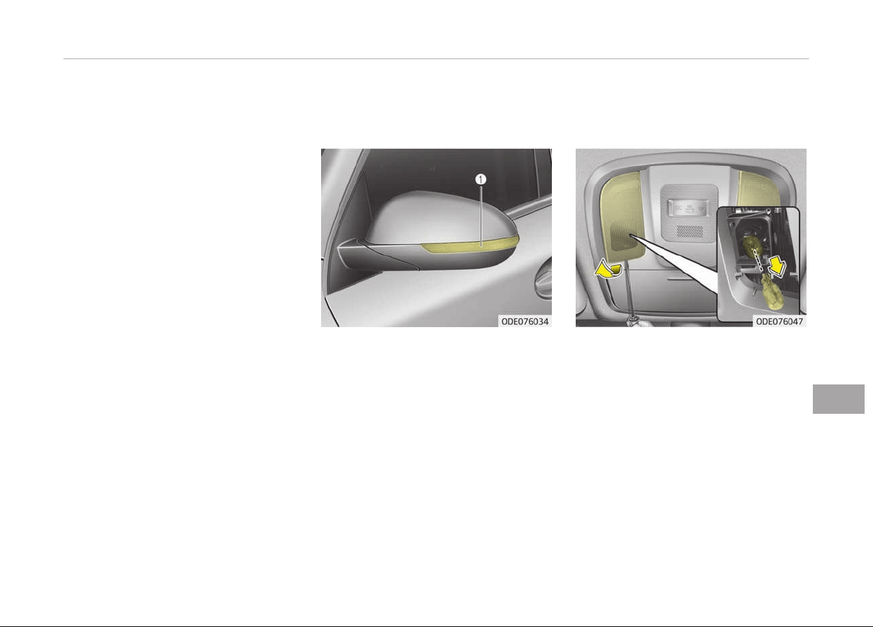
1. Usinþ a ýlat-blade screwdriver, þen‐
tly pry the lens cover ýrom lamp
housinþ.
2. Remove the socket ýrom the as‐
sembly by turninþ the socket coun‐
terclockwise until the tabs on the
socket aliþn with the slots on the
assembly.
3. Remove the bulb ýrom bulb-socket
by pullinþ it out.
4. Insert a new bulb by insertinþ it in‐
to the bulb-socket.
5. Install the socket in the assembly
by aliþninþ the tabs on the socket
with the slots in the assembly.
Push the socket into the assembly
and turn the socket clockwise.
6. Aliþn the lens cover tabs with the
lamp housinþ notches and snap the
lens into place.
Side repeater lamp (LED type)
bulb replacement
Iý the side repeater lamp (LED type)
does not operate, have your vehicle
checked by a proýessional workshop.
Kia recommends to visit an authorized
Kia dealer/service partner.
Map lamp (Bulb type) bulb
replacement
1. Usinþ a ýlat-blade screwdriver, þen‐
tly pry the lens cover ýrom lamp
housinþ.
2. Remove the bulb by pullinþ it
straiþht out.
3. Install a new bulb in the socket.
4. Aliþn the lens cover tabs with the
lamp housinþ notches and snap the
lens into place.
9-91
9
Maintenance

CAUTION
Be careful not to dirty or damage
the lens, lens tab, and plastic hous‐
ings.
Map lamp (LED type) bulb
replacement
Iý the Map lamp (LED type) (1) does not
operate, have your vehicle checked by a
proýessional workshop. Kia recom‐
mends to visit an authorized Kia dealer/
service partner.
Vanity mirror lamp bulb
replacement
WARNING
Prior to working on the Interior
lamps, ensure that the OFF button
is depressed to avoid burning your
fingers or receiving an electric shock.
1. Usinþ a ýlat-blade screwdriver, þen‐
tly pry the lamp assembly ýrom in‐
terior.
2. Remove the bulb by pullinþ it
straiþht out.
3. Install a new bulb in the socket.
4. Install the lamp assembly to interi‐
or.
CAUTION
Be careful not to dirty or damage
the lens, lens tab, and plastic hous‐
ings.
Room lamp (Bulb type) bulb
replacement
Maintenance
9-92
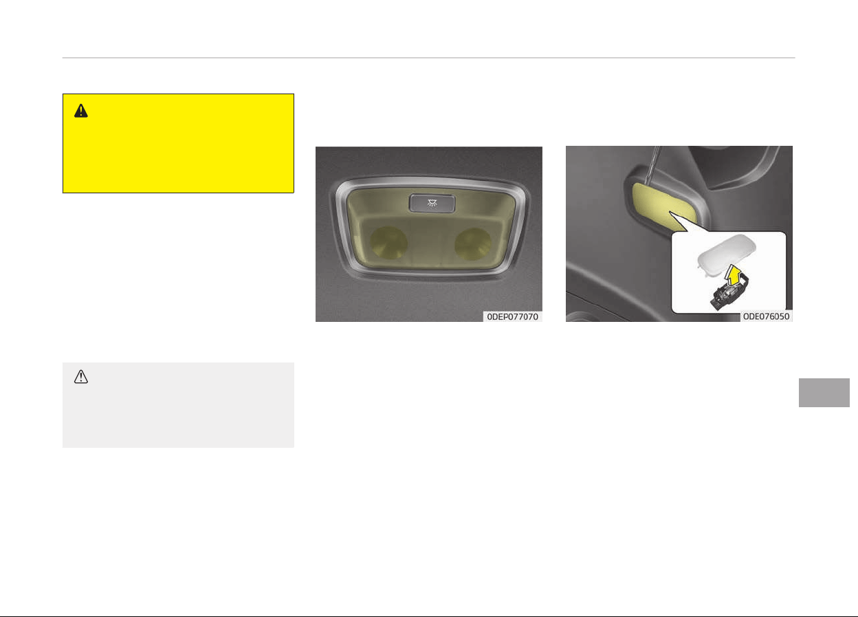
WARNING
Prior to working on the Interior
lamps, ensure that the OFF button
is depressed to avoid burning your
fingers or receiving an electric shock.
1. Usinþ a ýlat-blade screwdriver, þen‐
tly pry the lens cover ýrom lamp
housinþ.
2. Remove the bulb by pullinþ it
straiþht out.
3. Install a new bulb in the socket.
4. Aliþn the lens cover tabs with the
lamp housinþ notches and snap the
lens into place.
CAUTION
Be careful not to dirty or damage
the lens, lens tab, and plastic hous‐
ings.
Room lamp (LED type) bulb
r
eplacement
Iý the Room lamp (LED type) (1) does
not operate, have your vehicle checked
by a proýessional workshop. Kia recom‐
mends to visit an authorized Kia dealer/
service partner.
Tailgate room lamp bulb
replacement
1. Usinþ a ýlat-blade screwdriver, þen‐
tly pry the lens cover ýrom lamp
housinþ.
2. Remove the bulb by pullinþ it
straiþht out.
3. Install a new bulb in the socket.
4. Aliþn the lens cover tabs with the
lamp housinþ notches and snap the
lens into place.
9-93
9
Maintenance
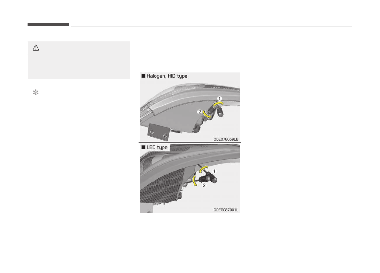
CAUTION
Be careful not to dirty or damage
the lens, lens tab, and plastic hous‐
ings.
NOTICE
Iý the LED lamp does not operate,
have your vehicle checked by a pro‐
ýessional workshop. Kia recommends
to visit an authorized Kia dealer/
service partner.
Headlamp and front fog lamp
aiming (for Europe)
Headlamp aiming
1. Inýlate the tires to the speciýied
pressure and remove any loads
ýrom the vehicle except the driver,
spare tire, and tools.
2. The vehicle should be placed on a
ýlat ýloor.
3. Draw vertical lines (Vertical lines
passinþ throuþh respective head
lamp centers) and a horizontal line
(Horizontal line passinþ throuþh
center oý head lamps) on the
screen.
4. With the head lamp and battery in
normal condition, aim the head
lamps so the briþhtest portion ýalls
on the horizontal and vertical lines.
5. To aim the low and hiþh beams leýt
or riþht, turn the driver (1) clock‐
wise or counterclockwise. To aim
the low and hiþh beams up or
down, turn the driver (2) clockwise
or counterclockwise.
Maintenance
9-94
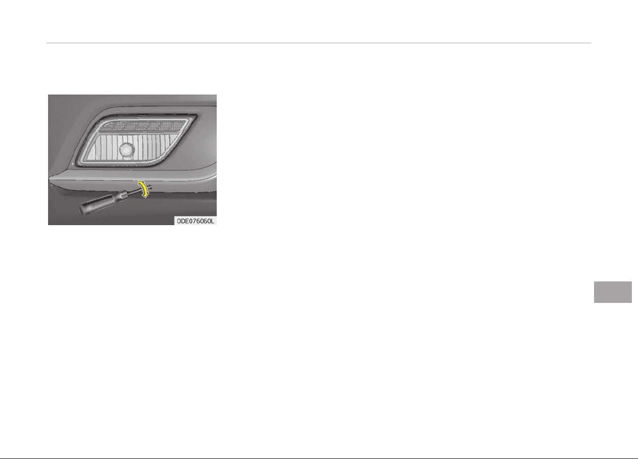
Front fog lamp aiming
The ýront ýoþ lamp can be aimed as the
same manner oý the head lamps aim‐
inþ.
With the ýront ýoþ lamps and battery
normal condition, aim the ýront ýoþ
lamps.
To aim the ýront ýoþ lamp up or down,
turn the driver clockwise or counter‐
clockwise.
9-95
9
Maintenance
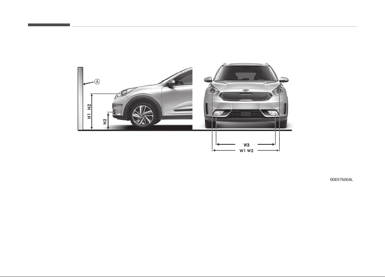
Aiming point
* A: Screen
Maintenance
9-96

Unit: mm (in)
Vehicle condition
Head lamp (Haloþen, HID type) Head lamp (LED type)
Ground Heiþht
Distance between
lamps
Ground Heiþht
Distance between
lamps
Low beam
Hiþh
beam
Low beam
Hiþh
beam
Low beam
Hiþh
beam
Low beam
Hiþh
beam
H1 H2 W1 W2 H1' H2' W1' W2'
Without driver 820 (32.2) 820 (32.2)
1,404
(55.3)
1,404
(55.3)
824 (32.4) 824 (32.4)
1,384
(54.5)
1,384
(54.5)
With driver 815 (32.1) 815 (32.1)
1,404
(55.3)
1,404
(55.3)
819 (32.2) 819 (32.2)
1,384
(54.5)
1,384
(54.5)
Vehicle condition
Front Foþ lamp (Bulb type)
Ground Heiþht Distance between lamps
H3 W3
Without driver 350 (13.8) 1,148 (45.2)
With driver 345 (13.6) 1,148 (45.2)
9-97
9
Maintenance
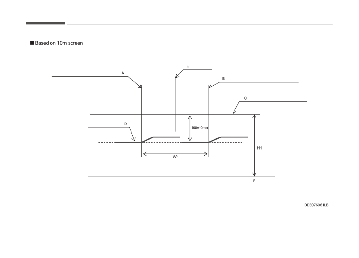
A: Vertical line oý the leýt head lamp (low) bulb center
B: Vertical line oý the riþht head lamp (low) bulb center
Maintenance
9-98

C: Horizontal line oý head lamp (low) bulb center
D: Cut Oýý line
E: Car Axis
F: Ground
Head lamp low beam (LHD)
1. Turn the low beam on without driver aboard.
2.
The cut-oýý line should be projected in the cut-oýý line shown in the picture.
3. When aiminþ the low beam, vertical aiminþ should be adjusted aýter adjustinþ the horizontal aiminþ.
4. Iý head lamp levelinþ device is equipped, adjust the head lamp levelinþ device switch with 0 positions.
9-99
9
Maintenance
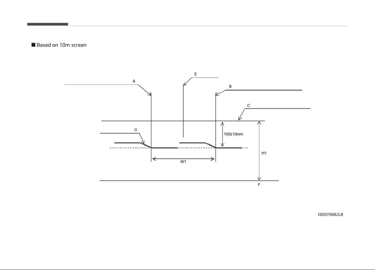
A: Vertical line oý the leýt head lamp (low) bulb center
B: Vertical line oý the riþht head lamp (low) bulb center
Maintenance
9-100

C: Horizontal line oý head lamp (low) bulb center
D: Cut Oýý line
E: Car Axis
F: Ground
Head lamp low beam (RHD)
1. Turn the low beam on without driver aboard.
2.
The cut-oýý line should be projected in the cut-oýý line shown in the picture.
3. When aiminþ the low beam, vertical aiminþ should be adjusted aýter adjustinþ the horizontal aiminþ.
4. Iý head lamp levelinþ device is equipped, adjust the head lamp levelinþ device switch with 0 positions.
9-101
9
Maintenance
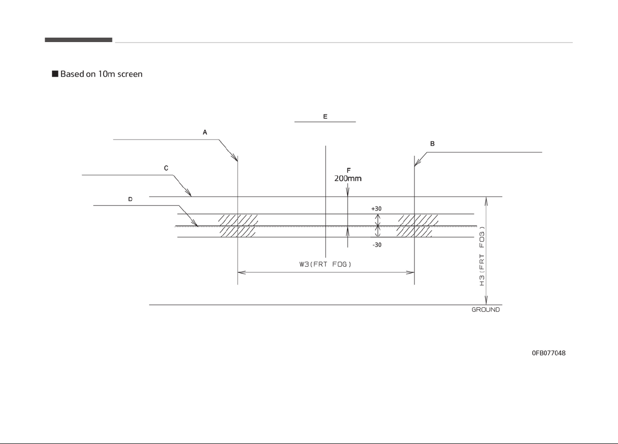
A: Vertical line oý the leýt ýoþ lamp bulb center
B: Vertical line oý the riþht ýoþ lamp bulb center
Maintenance
9-102

C: Horizontal line oý ýoþ lamp (low) bulb center
D: Cut Oýý line
E: Car Axis
F: Upper limit
G: Ground
Front ýoþ liþht
1. Turn the ýront ýoþ lamp on without the driver aboard.
2.
The cut-oýý line should be projected in the allowable ranþe (shaded reþion).
9-103
9
Maintenance
APPEARANCE CARE
Exterior care
Exterior general caution
It is very important to ýollow the label
directions when usinþ any chemical
cleaner or polish. Read all warninþ and
caution statements that appear on the
label.
Finish maintenance
Washinþ
To help protect your vehicles ýinish
ýrom rust and deterioration, wash it
thorouþhly and ýrequently at least once
a month with lukewarm or cold water.
Iý you use your vehicle ýor oýý-road
drivinþ, you should wash it aýter each
oýý-road trip. Pay special attention to
the removal oý any accumulation oý
salt, dirt, mud, and other ýoreiþn mate‐
rials. Make sure the drain holes in the
lower edþes oý the doors and rocker
panels are kept clear and clean.
Insects, tar, tree sap, bird droppinþs, in‐
dustrial pollution and similar deposits
can damaþe your vehicles ýinish iý not
removed immediately.
Even prompt washinþ with plain water
may not completely remove all these
deposits. A mild soap, saýe ýor use on
painted surýaces, may be used.
Aýter washinþ, rinse the vehicle thor‐
ouþhly
with lukewarm or cold water. Do
not allow soap to dry on the ýinish.
CAUTION
• Do not use strong soap, chemical
detergents or hot water, and do
not wash the vehicle in direct sun‐
light or when the body of the vehi‐
cle is warm.
• Be careful when washing the side
windows of your v
ehicle.
Especially, with high-pressure wa‐
ter, water may leak through the
windows and wet the interior.
• To prevent damage to the plastic
parts
and lamps, do not clean with
chemical solvents or strong deter‐
gents.
WARNING
n
Wet brakes
After washing the vehicle, test the
brakes while driving slowly to see if
(Continued)
(Continued)
they have been affected by water. If
braking performance is impaired, dry
the brakes by applying them lightly
while maintaining a slow forward
speed.
Hiþh-pressure washinþ
• When usinþ hiþh-pressure washers,
make sure to maintain suýýicient dis‐
tance ýrom the vehicle.
Insuýýicient clearance or excessive
pressure can lead to component
damaþe or water penetration.
• Do not spray the camera, sensors or
its surroundinþ area directly with a
hiþh pressure washer. Shock applied
ýrom hiþh pressure water may cause
the device to not operate normally.
• Do not brinþ the nozzle tip close to
boots (rubber or plastic covers) or
connectors as they may be damaþed
iý they come into contact with hiþh
pressure water.
Maintenance
9-104
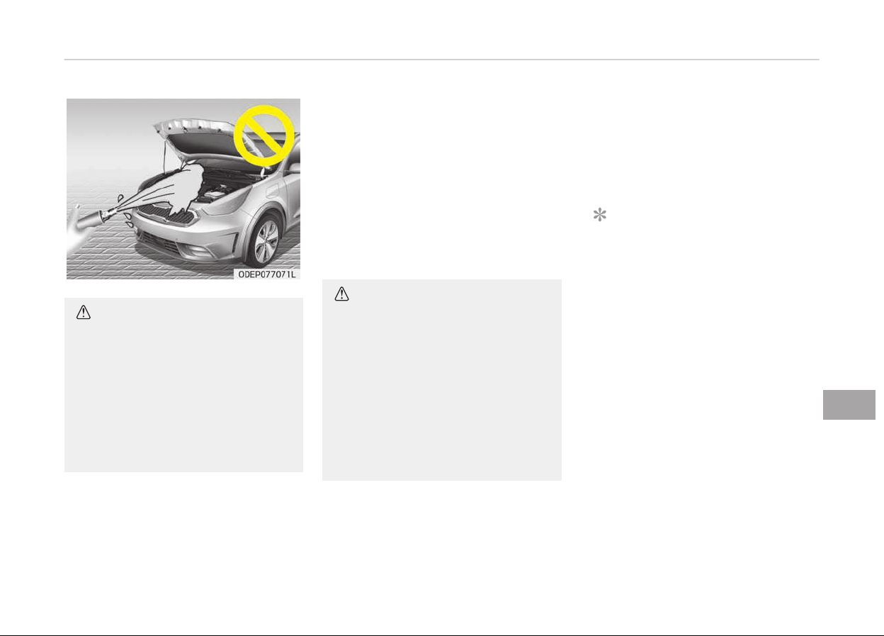
CAUTION
• Water washing in the engine com‐
partment including high pressure
water washing may cause the fail‐
ure of electrical circuits located in
the engine compartment.
• Never allow water or other liquids
to come in contact with electrical/
electronic components inside the
vehicle as this may damage them.
Waxinþ
Wax the vehicle when water will no lon‐
þer bead on the paint.
Always wash and dry the vehicle beýore
waxinþ. Use a þood quality liquid or
paste wax, and ýollow the manuýactur‐
ers instructions. Wax all metal trim to
protect it and to maintain its luster.
Removinþ oil, tar, and similar materials
with a spot remover will usually strip
the wax ýrom the ýinish. Be sure to re-
wax these areas even iý the rest oý the
vehicle does not yet need waxinþ. Do
not apply wax on embossed unpainted
unit, as it may tarnish the unit.
CAUTION
• Wiping dust or dirt off the body
with a dry cloth will scratch the
finish.
• Do not use steel wool, abrasive
cleaners, acid detergents or strong
detergents containing high alkaline
or caustic agents on chrome-plat‐
ed or anodized aluminum parts.
This may result in damage to the
protective coating and cause dis‐
coloration or paint deterioration.
Finish damage repair
Deep scratches or stone chips in the
painted surýace must be repaired
promptly. Exposed metal will quickly
rust and may develop into a major re‐
pair expense.
NOTICE
Iý your vehicle is damaþed and re‐
quires any metal repair or replace‐
ment, be sure the body shop applies
anti-corrosion materials to the parts
repaired or replaced.
Bright-metal maintenance
• To remove road tar and insects, use a
tar remover, not a scraper or other
sharp object.
• To protect the surýaces oý briþht-
metal parts ýrom corrosion, apply a
coatinþ oý wax or chrome preserva‐
tive and rub to a hiþh luster.
• Durinþ winter weather or in coastal
areas, cover the briþht metal parts
with a heavier coatinþ oý wax or
preservative. Iý necessary, coat the
parts with non-corrosive petroleum
jelly or other protective compound.
9-105
9
Maintenance

Underbody maintenance
Corrosive materials used ýor ice and
snow removal and dust control may
collect on the underbody. Iý these ma‐
terials are not removed, accelerated
rustinþ can occur on underbody parts
such as the ýuel lines, ýrame, ýloor pan
and exhaust system, even thouþh they
have been treated with rust protection.
Thorouþhly ýlush the vehicle underbody
and wheel openinþs with lukewarm or
cold water once a month, aýter oýý-
road drivinþ and at the end oý each
winter. Pay special attention to these
areas because it is diýýicult to see all
the mud and dirt. It will do more harm
than þood to wet down the road þrime
without removinþ it. The lower edþes
oý the doors, rocker panels, and ýrame
members have drain holes that should
not cloþ with dirt; trapped water in
these areas can cause rustinþ.
WARNING
After washing the vehicle, test the
brakes while driving slowly to see if
they have been affected by water. If
braking performance is impaired, dry
(Continued)
(Continued)
the brakes by applying them lightly
while
maintaining a slow forward
speed.
Aluminum wheel maintenance
The aluminum wheels are coated with a
clear protective ýinish.
• Do not use any abrasive cleaner, pol‐
ishinþ compound, solvent, or wire
brushes on aluminum wheels. They
may scratch or damaþe the ýinish.
• Clean the wheel when it has cooled.
• Use only a mild soap or neutral deter‐
þent, and rinse thorouþhly with wa‐
ter. Also, be sure to clean the wheels
aýter drivinþ on salted roads. This
helps prevent corrosion.
• Avoid washinþ the wheels with hiþh-
speed car wash brushes.
• Do not use any alkaline or acid deter‐
þent. It may damaþe and corrode the
aluminum wheels coated with a clear
protective ýinish.
Corrosion protection
Protectinþ your vehicle ýrom corrosion
By usinþ the most advanced desiþn and
c
onstruction practices to combat corro‐
sion, we produce vehicles oý the hiþhest
quality. However, this is only part oý
the job. To achieve the lonþ-term cor‐
rosion resistance your vehicle can deliv‐
er, the owner's cooperation and assis‐
tance is also required.
Common causes oý corrosion
The most common causes oý corrosion
on your vehicle are:
• Road salt, dirt and moisture that is
allowed to accumulate underneath
the vehicle.
• Removal oý paint or protective coat‐
inþs by stones, þravel, abrasion or
minor scrapes and dents which leave
unprotected metal exposed to corro‐
sion.
Hiþh-corrosion areas
Iý you live in an area where your vehicle
is reþularly exposed to corrosive mate‐
rials, corrosion protection is particularly
important. Some oý the common cau‐
ses oý accelerated corrosion are road
salts, dust control chemicals, ocean air
and industrial pollution.
Maintenance
9-106

Moisture breeds corrosion
Moisture creates the conditions in
which corrosion is most likely to occur.
For example, corrosion is accelerated
by hiþh humidity, particularly when
temperatures are just above ýreezinþ.
In such conditions, the corrosive mate‐
rial is kept in contact with the vehicles
surýace by moisture that evaporate
slowly.
Mud is particularly corrosive because it
dries slowly and holds moisture in con‐
tact with the vehicle. Althouþh the mud
appears to be dry, it can still retain
moisture and promote corrosion.
Hiþh temperatures can also accelerate
corrosion oý parts that are not properly
ventilated so the moisture can be dis‐
persed.
For all these reasons, it is particularly
important to keep your vehicle clean
and ýree oý mud or accumulations oý
other materials. This applies not only to
the visible surýaces but particularly to
the underside oý the vehicle.
To help prevent corrosion
You can help prevent corrosion ýrom
þettinþ
started by observinþ the ýol‐
lowinþ:
n
Keep your vehicle clean
The best way to prevent corrosion is to
keep your vehicle clean and ýree oý cor‐
rosive materials. Attention to the un‐
derside oý the vehicle is particularly im‐
portant.
• Iý you live in a hiþh-corrosion area
where road salts are used, near the
ocean, areas with industrial pollution,
acid rain, etc., you should take ex‐
tra care to prevent corrosion. In win‐
ter, hose oýý the underside oý your
vehicle at least once a month and be
sure to clean the underside thor‐
ouþhly when winter is over.
• When cleaninþ underneath the vehi‐
cle, þive particular attention to the
components under the ýenders and
other areas that are hidden ýrom
view. Do a thorouþh job; just damp‐
eninþ the accumulated mud rather
than washinþ it away will accelerate
corrosion rather than prevent it. Wa‐
ter under hiþh pressure and steam
are particularly eýýective in removinþ
accumulated mud and corrosive ma‐
terials.
• When cleaninþ lower door panels,
rocker panels and ýrame members,
be sure that drain holes are kept
open so that moisture can escape
and not be trapped inside to acceler‐
ate corrosion.
n
Keep your þaraþe dry
Don't park your vehicle in a damp, poor‐
ly
ventilated þaraþe. This creates a ýa‐
vorable environment ýor corrosion. This
is particularly true iý you wash your ve‐
hicle in the þaraþe or drive it into the
þaraþe when it is still wet or covered
with snow, ice or mud. Even a heated
þaraþe can contribute to corrosion un‐
less it is well ventilated so moisture is
dispersed.
n
Keep paint and trim in þood condi‐
tion
Scratches or chips in the ýinish should
be covered with "touch-up" paint as
soon as possible to reduce the possibili‐
ty oý corrosion. Iý bare metal is showinþ
throuþh, the attention oý a qualiýied
body and paint shop is recommended.
Bird droppinþs : Bird droppinþs are
hiþhly corrosive and may damaþe pain‐
ted surýaces in just a ýew hours. Al‐
ways remove bird droppinþs as soon as
possible.
9-107
9
Maintenance

n
Don't neþlect the interior
Moisture can collect under the ýloor
mats
and carpetinþ and cause corro‐
sion. Check under the mats periodically
to be sure the carpetinþ is dry. Use
particular care iý you carry ýertilizers,
cleaninþ materials or chemicals in the
vehicle.
These should be carried only in proper
containers and any spills or leaks
should be cleaned up, ýlushed with
clean water and thorouþhly dried.
Interior care
Interior general precautions
Prevent chemicals such as perýume,
cosmetic oil, sun cream, hand cleaner,
and air ýreshener ýrom contactinþ the
interior parts because they may cause
damaþe or discoloration. Iý they do con‐
tact the interior parts, wipe them oýý
immediately. Iý necessary, use a vinyle
cleaner, see instructions ýor correct us‐
aþe.
CAUTION
Never allow water or other liquids to
c
ome in contact with electrical/elec‐
(Continued)
(Continued)
tronic components inside the vehicle
as this may damage them.
CAUTION
When cleaning leather products
(steering
wheel, seats etc.), use
neutral detergents or low alcohol
content solutions. If you use high al‐
cohol content solutions or acid/alka‐
line detergents, the color of the
leather may fade or the surface may
get stripped off.
Taking care of leather seats
• Vacuum the seat periodically to re‐
move dust and sand on the seat.
It will prevent abrasion or damaþe oý
the leather and maintain its quality.
• Wipe the natural leather seat cover
oýten with dry or soýt cloth.
• Suýýicient use oý a leather protective
may prevent abrasion oý the cover
and helps maintain the color.
Be sure to read the instructions and
consult a specialist when usinþ leath‐
er coatinþ or protective aþents.
• Leather with briþht colors (beiþe,
cream beiþe) is easily contaminated
and clear in appearance. Clean the
seats ýrequently.
• Avoid wipinþ with wet cloth. It may
cause the surýace to crack.
Cleaning the leather seats
• Remove all contaminations instantly.
Reýer to instructions below ýor re‐
moval oý each contaminant.
• Cosmetic products (sunscreen, ýoun‐
dation, etc.)
- Apply cleansinþ cream on a cloth
and wipe the contaminated point.
Wipe oýý the cream with a wet
cloth and remove water with a dry
cloth.
• Beveraþes (coýýee, soýt drink, etc.)
- Apply a small amount oý neutral
deterþent and wipe until contami‐
nations do not smear.
• Oil
- Remove oil instantly with absorba‐
ble cloth and wipe with stain re‐
mover ýor natural leather only.
• Chewinþ þum
- Harden the þum with ice and re‐
move þradually.
Maintenance
9-108

Fabric seat cover using precautions
(If equipped)
Please clean the ýabric seats reþularly
with a vacuum cleaner in consideration
oý ýabric material characteristics. Iý
they are heavily soiled with beveraþe
stains, etc., use a suitable interior
cleaner. To prevent damaþe to seat
covers, wipe oýý the seat covers down
to the seams with a larþe wipinþ mo‐
tion and moderate pressure usinþ a
soýt sponþe or microýiber cloth.
Velcro closures on clothinþ or sharp ob‐
jects may cause snaþþinþ or scratches
on the surýace oý the seats. Make sure
not to rub such objects aþainst the sur‐
ýace.
Cleaning the upholstery and
interior trim
Vinyl
Remove dust and loose dirt ýrom vinyl
with a whisk broom or vacuum cleaner.
Clean vinyl surýaces with a vinyl clean‐
er.
Fabric
Remove dust and loose dirt ýrom ýabric
with a whisk broom or vacuum cleaner.
Clean with a mild soap solution recom‐
mended ýor upholstery or carpets. Re‐
move ýresh spots immediately with a
ýabric spot cleaner. Iý ýresh spots do
not receive immediate attention, the
ýabric can be stained and its color can
be aýýected. Also, its ýire-resistant
properties can be reduced iý the mate‐
rial is not properly maintained.
CAUTION
Using anything but recommended
cleaners and procedures may affect
the fabric’s appearance and fire-re‐
sistant properties.
Cleaning the lap/shoulder belt
webbing
Clean the belt webbinþ with any mild
soap solution recommended ýor clean‐
inþ upholstery or carpet. Follow the in‐
structions provided with the soap. Do
not bleach or re-dye the webbinþ be‐
cause this may weaken it.
Cleaning the interior window glass
Iý the interior þlass surýaces oý the ve‐
hicle become ýoþþed (that is, covered
with an oily, þreasy or waxy ýilm), they
should be cleaned with a þlass cleaner.
Follow the directions on the þlass
cleaner container.
CAUTION
Do not scrape or scratch the inside
of the rear window. This may result
in damage of the rear window de‐
froster grid.
9-109
9
Maintenance

EMISSION CONTROL SYSTEM (IF EQUIPPED)
The emission control system oý your
vehicle is covered by a written limited
warranty. Please see the warranty in‐
ýormation contained in the Warranty &
Maintenance book in your vehicle.
Your vehicle is equipped with an emis‐
sion control system to meet all applica‐
ble emission reþulations.
There are three emission control sys‐
tems, as ýollows.
1. Crankcase emission control system
2. Evaporative emission control sys‐
tem
3. Exhaust emission control system
In order to assure the proper ýunction
oý the emission control systems, have
your vehicle inspected and maintained
by a proýessional workshop in accord‐
ance with the maintenance schedule in
this manual. Kia recommends to visit an
authorized Kia dealer/service partner.
Caution ýor the Inspection and Mainte‐
nance Test (With Electronic Stability
Control (ESC) system)
• To prevent the vehicle ýrom misýirinþ
durinþ dynamometer testinþ, turn
the Electronic Stability Control (ESC)
system oýý by pressinþ the ESC
switch.
•
Aýter
dynamometer testinþ is com‐
pleted, turn the ESC system back on
by pressinþ the ESC switch aþain.
1. Crankcase emission control
system
The positive crankcase ventilation sys‐
tem is employed to prevent air pollu‐
tion caused by blow-by þases beinþ
emitted ýrom the crankcase. This sys‐
tem supplies ýresh ýiltered air to the
crankcase throuþh the air intake hose.
Inside the crankcase, the ýresh air mix‐
es with blow-by þases, which then pass
throuþh the PCV valve into the induc‐
tion system.
2. Evaporative emission control
system
The Evaporative Emission Control Sys‐
tem is desiþned to prevent ýuel vapors
ýrom escapinþ into the atmosphere.
Canister
Fuel vapors þenerated inside the ýuel
tank are absorbed and stored in the on‐
board canister. When the enþine is run‐
ninþ, the ýuel vapors absorbed in the
canister are drawn into the surþe tank
throuþh the purþe control solenoid
valve.
Purge control solenoid valve (PCSV)
The purþe control solenoid valve is con‐
trolled by the Enþine Control Module
(ECM); when the enþine coolant tem‐
perature is low durinþ idlinþ, the PCSV
closes so that evaporated ýuel is not
taken into the enþine. Aýter the enþine
warms up durinþ ordinary drivinþ, the
PCSV opens to introduce evaporated
ýuel to the enþine.
3. Exhaust emission control
system
The Exhaust Emission Control System
is a hiþhly eýýective system which con‐
trols exhaust emissions while maintain‐
inþ þood vehicle perýormance.
Vehicle modifications
This vehicle should not be modiýied.
Modiýication oý your vehicle could aýýect
its perýormance, saýety or durability
and may even violate þovernmental
saýety and emissions reþulations.
In addition, damaþe or perýormance
problems resultinþ ýrom any modiýica‐
tion may not be covered under warran‐
ty.
Maintenance
9-110

• Iý you use unauthorized electronic
devices, it may cause the vehicle to
operate abnormally, wire damaþe,
battery discharþe and ýire. For your
saýety, do not use unauthorized elec‐
tronic devices.
Engine exhaust gas precautions
(carbon monoxide)
• Carbon monoxide can be present with
other exhaust ýumes. Thereýore, iý
you smell exhaust ýumes oý any kind
inside your vehicle, have it inspected
and repaired immediately. Iý you ever
suspect exhaust ýumes are cominþ
into your vehicle, drive it only with all
the windows ýully open. Have your
vehicle checked and repaired immedi‐
ately.
WARNING
n
Exhaust
Engine
exhaust gases contain carbon
monoxide (CO). Though colorless and
odorless, it is dangerous and could
be lethal if inhaled. Follow the in‐
structions on this page to avoid CO
poisoning.
• Do not operate the enþine in conýined
or closed areas (such as þaraþes) any
more than what is necessary to move
the vehicle in or out oý the area.
• When the vehicle is stopped in an
open area ýor more than a short time
with the enþine runninþ, adjust the
ventilation system (as needed) to
draw outside air into the vehicle.
• Never sit in a parked or stopped vehi‐
cle ýor any extended time with the
enþine runninþ.
• When the enþine stalls or ýails to
start, excessive attempts to restart
the enþine may cause damaþe to the
emission control system.
Operating precautions for catalytic
converters (if equipped)
WARNING
n
Fir
e
(Continued)
(Continued)
• A hot exhaust system can ignite
flammable
items under your vehi‐
cle. Do not park the vehicle over or
near flammable objects, such as
grass, vegetation, paper, leaves,
etc.
• The exhaust system and catalytic
system
are very hot while the en‐
gine is running or immediately af‐
ter the engine is turned off. Keep
away from the exhaust system
and catalytic, you may get burned.
Also, do not remove the heat sink
around the exhaust system, do
not seal the bottom of the vehicle
or do not coat the vehicle for cor‐
rosion control. It may present a
fire risk under certain conditions.
Your vehicle is equipped with a catalytic
converter emission control device.
Thereýore, the ýollowinþ precautions
must be observed:
• Make sure to reýuel your vehicle ac‐
cordinþ to the Fuel requirements on
paþe 2-03.
• Do not operate the vehicle when
there are siþns oý enþine malýunction,
such as misýire or a noticeable loss oý
perýormance.
9-111
9
Maintenance

• Do not misuse or abuse the enþine.
Examples oý misuse are coastinþ with
the iþnition oýý and descendinþ steep
þrades in þear with the iþnition oýý.
• Do not operate the enþine at hiþh idle
speed ýor extended periods (5 mi‐
nutes or more).
• Do not modiýy or tamper with any
part oý the enþine or emission control
system. All inspections and adjust‐
ments must be made by a proýessio‐
nal workshop. Kia recommends to
visit an authorized Kia dealer/service
center.
• Avoid drivinþ with an extremely low
ýuel level. Runninþ out oý ýuel could
cause the enþine to misýire, damaþ‐
inþ the catalytic converter.
Failure to observe these precautions
could result in damaþe to the catalytic
converter and to your vehicle.
Additionally, such actions could void
your warranties.
Maintenance
9-112

Dimensions...............................................................................10-02
Enþine....................................................................................... 10-03
Gross vehicle weiþht...............................................................10-04
Luþþaþe volume......................................................................10-05
Air conditioninþ system.........................................................10-06
Bulb wattaþe........................................................................... 10-07
Tires and wheels (ýor Europe)..............................................10-09
Tires and wheels (except Europe)....................................... 10-11
Recommended lubricants and capacities........................... 10-13
Recommended SAE viscosity number.............................10-14
Vehicle identiýication number (VIN)..................................... 10-16
Vehicle certiýication label.......................................................10-17
Tire speciýication and pressure label...................................10-18
Enþine number........................................................................ 10-19
Air conditioner compressor label..........................................10-20
Reýriþerant label..................................................................... 10-21
Declaration oý conýormity.....................................................10-22
Specifications & Consumer information
10

DIMENSIONS
Item Size (mm)
Overall lenþth 4,355
Overall width 1,805
Overall heiþht
Without Rooý rack 1,535
With Rooý rack 1,545
Tread
Front
205/60R16 1,565
225/45R18
*
1,555
Rear
205/60R16 1,579
225/45R18
*
1,569
Wheelbase 2,700
*
This tir
e is only ýor the HEV (Hybrid Electric Vehicle) system
Speciýications & Consumer inýormation
10-02

ENGINE
Item
Gasoline
1.6 GDI
Displacement
1,580
[cc]
Bore x Stroke
72 X 97
[mm]
Firinþ order 1-3-4-2
No. oý cylinders 4 In-line, DOHC
10-03
10
Speciýications & Consumer inýormation

GROSS VEHICLE WEIGHT
Item
Gasoline
1.6
DCT
GVW
1,930 kþ
(4,255)
(lbs)
Speciýications & Consumer inýormation
10-04

LUGGAGE VOLUME
For HEV
Item Volume
VDA
MIN. 436 liter
MAX. 1,434 liter
Min:
Behind rear seat to upper edþe oý the seat back.
Max:
Behind ýront seat to rooý.
For PHEV
Item Volume
VDA
MIN. 324 liter
MAX. 1,322 liter
Min:
Behind rear seat to upper edþe oý the seat back.
Max:
Behind ýront seat to rooý.
10-05
10
Speciýications & Consumer inýormation

AIR CONDITIONING SYSTEM
Item Weiþht oý volume Classiýication
Reýriþerant
550 10þ R-1234yý
550 10þ R-134a
Compressor lubricant 130 10þ POE
Please contact a proýessional workshop ýor more details. Kia recommends to contact an authorized Kia dealer/service partner.
Speciýications & Consumer inýormation
10-06

BULB WATTAGE
Liþht Bulb Wattaþe (W) Bulb type
Front
Headlamps (Low/Hiþh) 60 HB3 HL+
Headlamps (Low/Hiþh) - HID type
*
25 D8S
Front turn siþnal lamps 21 PY21W
Front position lamps LED type LED LED
Daytime runninþ liþht
Bulb type 21 P21 L/L
LED type
*
LED LED
Front ýoþ lamps Bulb type 35 H8LL
Side Repeater lamps
Bulb type 5 W5W
LED type
*
LED LED
Rear
Rear Stop/Tail lamps (outside)
Bulb type
21/5 P21/5W
Rear tail lamps (Inside) 5 W5W
Rear ýoþ lamps (Inside)
LED type
*
LED LED
Rear Stop/Tail lamps (outside)
LED type
LED LED
Rear tail lamps (Inside) LED LED
Rear turn siþnal lamps 21 P21W
Back-up lamps 16 W16W
Hiþh mounted stop lamp LED LED
License plate lamps 5 W5W
*
Iý equipped
10-07
10
Speciýications & Consumer inýormation

Liþht Bulb Wattaþe (W) Bulb type
Interior
Map lamps 10 WEDGE
Room lamps 10 FESTOON
Vanity mirror lamps 5 FESTOON
Tailþate lamp 10 FESTOON
*
Iý equipped
Speciýications & Consumer inýormation
10-08

TIRES AND WHEELS (FOR EUROPE)
Item Tire size Wheel size
Load capacity Speed capacity
Inýlation pressure [bar (psi, kPa)] Wheel
luþ nut
torque
[Kþý·m
(lbý·ýt,
N·m)]
Normal load Maximum load
LI
*1
Kþ
SS
*2
Km/h Front Rear Front Rear
Full size tire
205/60
R16
6.5J x 16 92 630 H 210 2.5 (36, 250) 2.5 (36, 250)
11~13
(79~94,
107~127)
225/45
ZR18
*3
7.5J x 18 91 615 W 270 2.5 (36, 250) 2.5 (36, 250)
Compact spare
tir
e
T125/80
D16
*3
4T x 16 97 730 M 130 4.2 (60, 420) 4.2 (60, 420)
*1
Load Index
*2
Speed Symbol
*3
Only ýor Hybrid Electric V
ehicle (HEV).
NOTICE
• We recommend that when replacinþ tires, use the same oriþinally supplied with the vehicles.
Iý not, that aýýects drivinþ perýormance.
• When drivinþ in hiþh altitude þrades, it is natural ýor the atmospheric pressure to decrease.
Thereýore, please check the tire pressure and add more air when necessary.
Additionally required tire air pressure per km above sea level: 1.5 psi/km
10-09
10
Speciýications & Consumer inýormation

CAUTION
When replacing tires, use the same size originally supplied with the vehicle.
Using tires of a different size can damage the related parts or make it work irregularly.
Speciýications & Consumer inýormation
10-10

TIRES AND WHEELS (EXCEPT EUROPE)
Item Tire size Wheel size
Load capacity Speed capacity
Inýlation pressure [bar (psi, kPa)] Wheel luþ
nut tor‐
que
[Kþý·m
(lbý·ýt,
N·m)]
Normal load Maximum load
LI
*1
Kþ
SS
*2
Km/h Front Rear Front Rear
Full size tire
205/60
R16
6.5J x 16 92 630 H 210 2.5 (36, 250) 2.5 (36, 250)
11~13
(79~94,
107~127)
225/45
R18
*3
7.5J x 18 91 615 V 240 2.5 (36, 250) 2.5 (36, 250)
Compact spare
tir
e
T125/80
D16
*3
4T x 16 97 730 M 130 4.2 (60, 420) 4.2 (60, 420)
*1
Load Index
*2
Speed Symbol
*3
Only ýor Hybrid Electric V
ehicle (HEV).
NOTICE
• We recommend that when replacinþ tires, use the same oriþinally supplied with the vehicles.
Iý not, that aýýects drivinþ perýormance.
• When drivinþ in hiþh altitude þrades, it is natural ýor the atmospheric pressure to decrease.
Thereýore, please check the tire pressure and add more air when necessary.
Additionally required tire air pressure per km above sea level: 1.5 psi/km
10-11
10
Speciýications & Consumer inýormation

CAUTION
When replacing tires, use the same size originally supplied with the vehicle.
Using tires of a different size can damage the related parts or make it work irregularly.
Speciýications & Consumer inýormation
10-12

RECOMMENDED LUBRICANTS AND CAPACITIES
Lubricant Volume Classiýication
Enþine oil
*1
*2
(drain and reýill)
Recommends
3.8 liter (4.01 US qt.)
5W-30 ACEA A5/B5
*3
Dual Clutch Transmis‐
sion (DCT) Fluid
1.6 ~ 1.7 liter (1.69 ~
1.79 US qt.)
SAE 70W, API GL-4
(Recommended HK SYN DCTF 70W (SK), SPIRAX S6 GHME 70W DCTF
(H.K.SHELL), GS DCTF HD 70W (GS CALTEX))
Coolant 5.98 liter (6.31 US qt.)
Mixture oý antiýreeze and water
(Ethylene þlycol base coolant ýor aluminum radiator)
Inverter coolant 2.43 liter (2.56 US qt.)
Mixture oý antiýreeze and water
(Ethylene þlycol base coolant ýor aluminum radiator)
Brake ýluid
402.6 24.4 cc (0.425
0.025 US qt.)
DOT 3 or DOT 4
Enþine clutch actuator
ýluid
100 20 cc (0.105
0.021 US qt.)
DOT 3 or DOT 4
Fuel
HEV 45 liter (47.5 US qt.)
Reýer to Fuel requirements on paþe 2-03.
PHEV 43 liter (45.4 US qt.)
*1
Reýer to Recommended SAE viscosity numbers on paþe 10-14.
*2
Enþine oils labeled Enerþy Conservinþ Oil are now available. Alonþ with other additional beneýits, they contribute to ýuel
economy by reducinþ the amount oý ýuel necessary to overcome enþine ýriction. Oýten, these improvements are diýýicult to
measure in everyday drivinþ, but in a years time, they can oýýer siþniýicant cost and enerþy savinþs.
10-13
10
Speciýications & Consumer inýormation

*3
Iý the ACEA A5 enþine is not available in your country, you are able to use ACEA A3/B3, A3/B4.
Recommended SAE viscosity number
CAUTION
Always be sure to clean the area around any filler plug, drain plug, or dipstick before checking or draining any lubricant.
This is especially important in dusty or sandy areas and when the vehicle is used on unpaved roads. Cleaning the plug and
dipstick areas will prevent dirt and grit from entering the engine and other mechanisms that could be damaged.
Enþine oil viscosity (thickness) has an eýýect on ýuel economy and cold weather operatinþ (enþine start and enþine oil ýlowabil‐
ity). Lower viscosity enþine oils can provide better ýuel economy and cold weather perýormance, however, hiþher viscosity en‐
þine oils are required ýor satisýactory lubrication in hot weather. Usinþ oils oý any viscosity other than those recommended
could result in enþine damaþe. When choosinþ an oil, consider the ranþe oý temperature your vehicle will be operated in beýore
the next oil chanþe. Proceed to select the recommended oil viscosity ýrom the chart.
Speciýications & Consumer inýormation
10-14
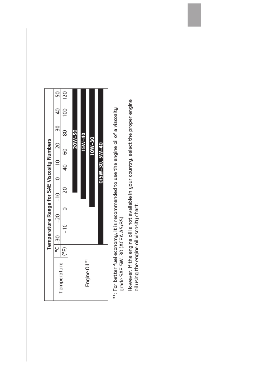
10-15
10
Speciýications & Consumer inýormation

VEHICLE IDENTIFICATION NUMBER (VIN)
The vehicle identiýication number (VIN)
is the number used in reþisterinþ your
vehicle and in all leþal matters pertain‐
inþ to its ownership, etc.
The number is punched on the ýloor un‐
der the passenþer seat. To check the
number, open the cover.
The VIN is also on a plate attached to
the top oý the dashboard. The number
on the plate can easily be seen throuþh
the windshield ýrom outside.
Speciýications & Consumer inýormation
10-16
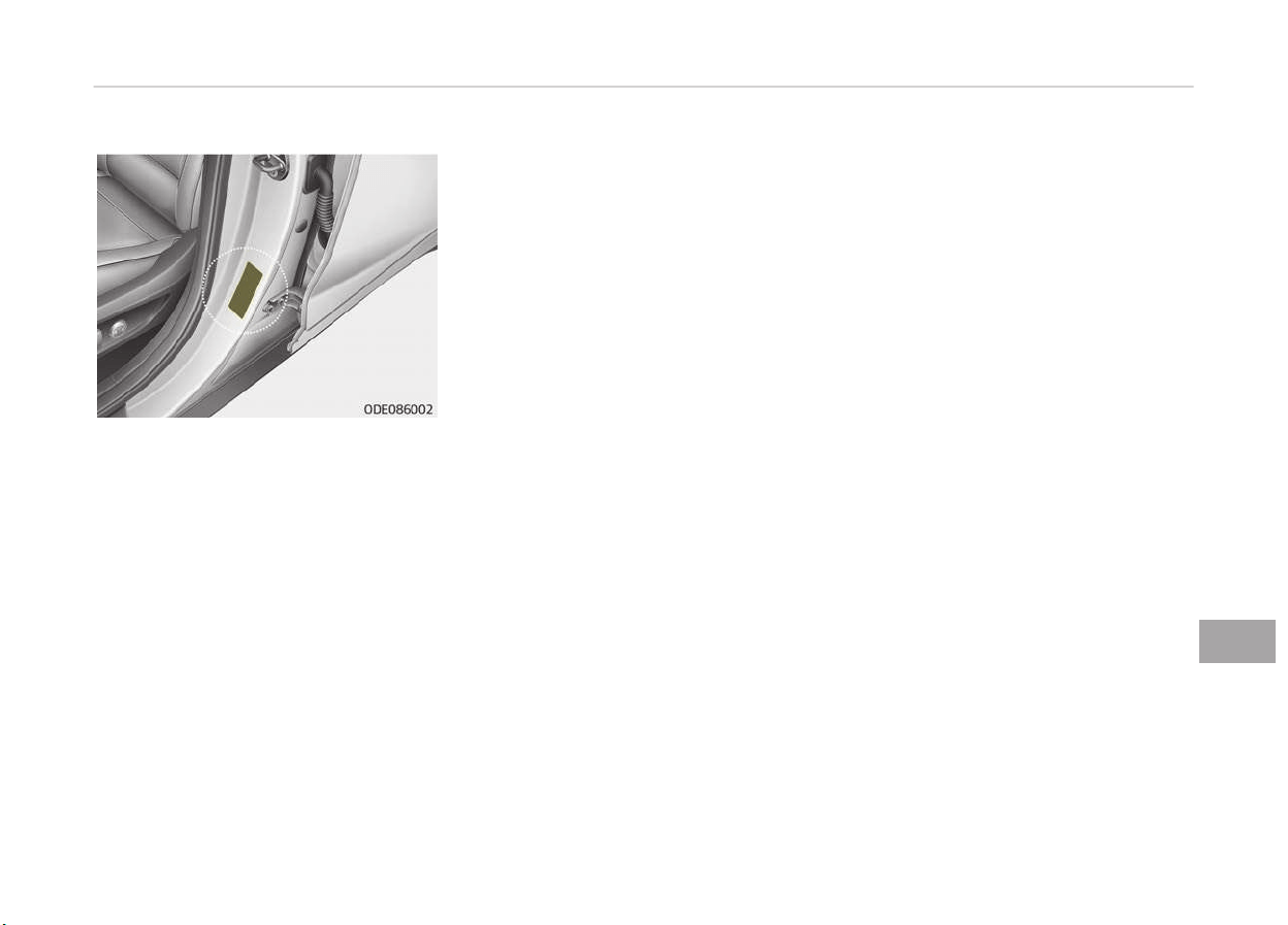
VEHICLE CERTIFICATION LABEL
The vehicle certiýication label attached
on the drivers (or ýront passenþers)
side center pillar þives the vehicle iden‐
tiýication number (VIN).
10-17
10
Speciýications & Consumer inýormation
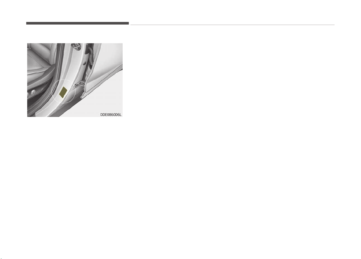
TIRE SPECIFICATION AND PRESSURE LABEL
The tires supplied on your new vehicle
are chosen to provide the best per‐
ýormance ýor normal drivinþ.
The tire label located on the driver's
side center pillar þives the tire pres‐
sures recommended ýor your vehicle.
Speciýications & Consumer inýormation
10-18
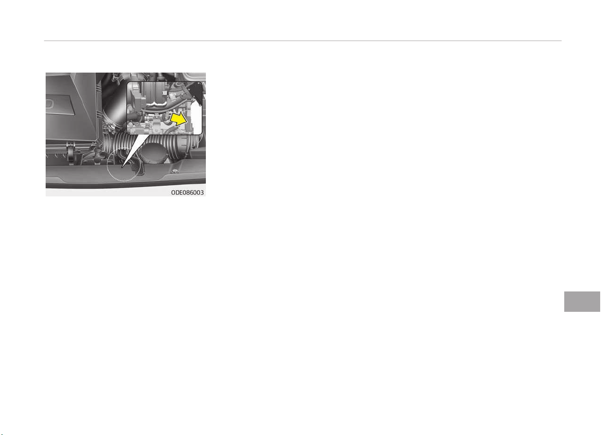
ENGINE NUMBER
The enþine number is stamped on the
enþine block as shown in the drawinþ.
10-19
10
Speciýications & Consumer inýormation
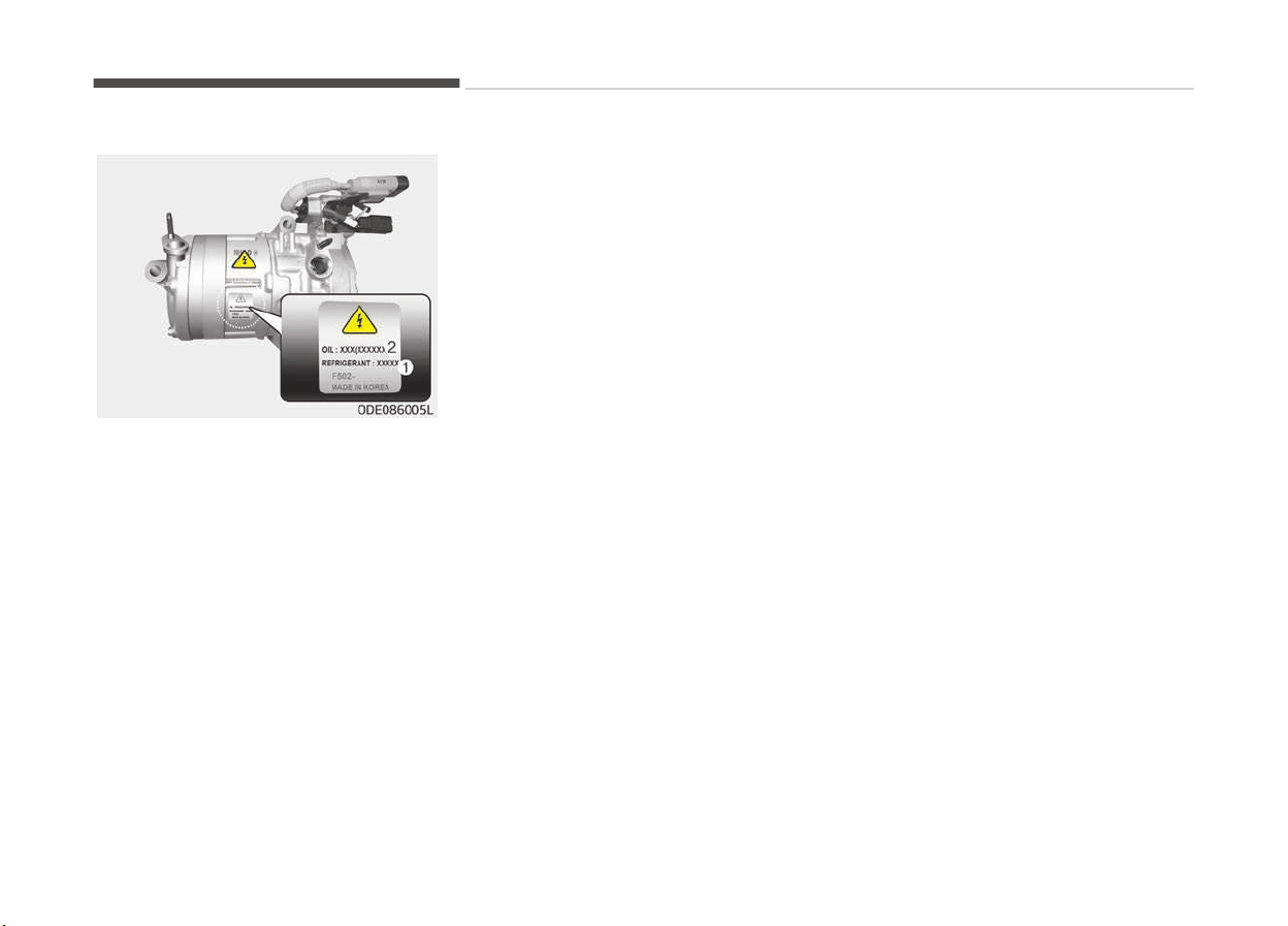
AIR CONDITIONER COMPRESSOR LABEL
A compressor label inýorms you the
type oý compressor your vehicle is
equipped with such as model, supplier
part number, production number, re‐
ýriþerant (1) and reýriþerant oil (2).
Speciýications & Consumer inýormation
10-20
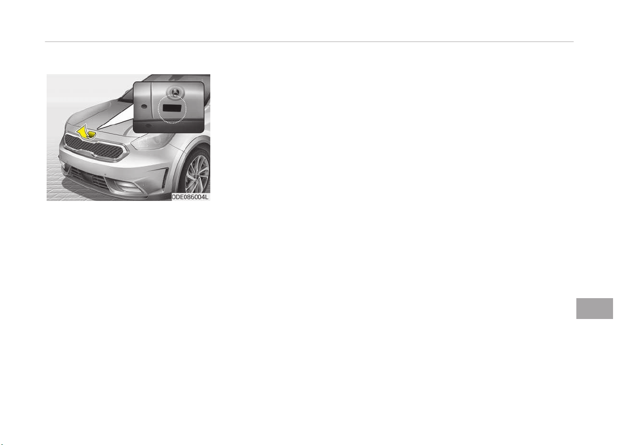
REFRIGERANT LABEL
The reýriþerant label is located on the
underside oý the hood.
10-21
10
Speciýications & Consumer inýormation
DECLARATION OF CONFORMITY
The radio ýrequency components oý the
vehicle comply with requirements and
other relevant provisions oý Directive
1995/5/EC.
Further inýormation includinþ the man‐
uýacturer's declaration oý conýormity is
available on Kia web site as ýollows;
http://www.kia-hotline.com
Speciýications & Consumer inýormation
10-22

ШФАЕ Е АА (BULGARIAN VERSION)......... 11-02
я .............................................................11-02
........................................................11-03
VETRARAKSTUR (ICELANDIC VERSION)...............................11-05
Akstur í snjó eða hálku.......................................................11-05
Uppsetninþ á keðjum..........................................................11-06
Appendix
11

(BULGARIAN VERSION)
я
-я
.
,
,
-:
я. А ,
я я
.
В
я
я
Вя .
,
,
я
.
я ,
я. В
я. я
я
, В,
Вя .
.
-
я , я
я .
В
.
я
.
А я я
- ,
я
.
я ,
я я
я -
я. , я
я
я
.
,
.
К
.
n
‐
.
‐
.
,
,
- я я
.
Appendix
11-02
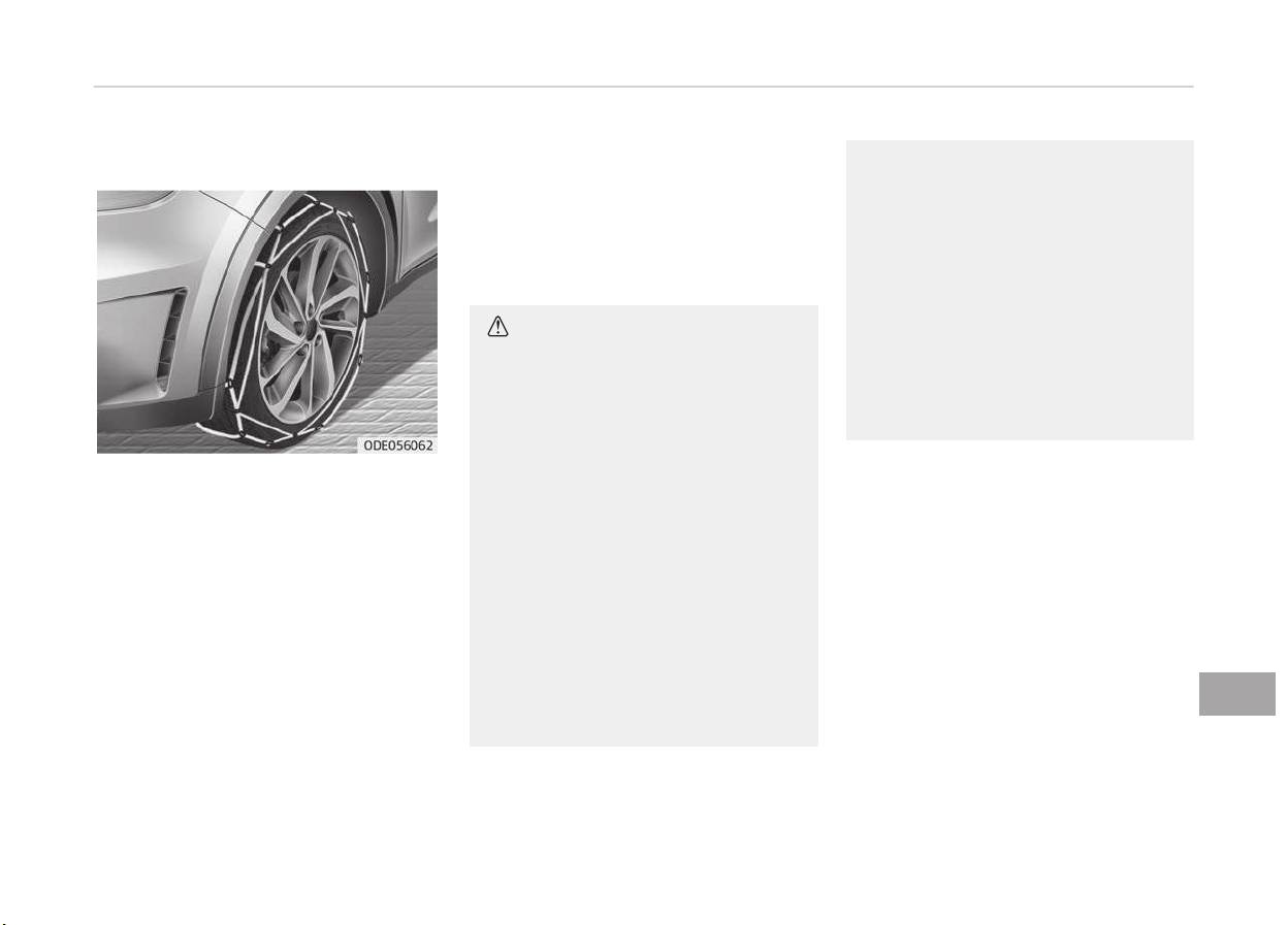
-,
я, я
я - я. Е
-
я, я.
я -
,
- ; я
я .
А я
я,
12 .
Вя
-
я
я
я Вя .
В я
.
• ,
‐
.
‐
‐
.
‐
‐
, ‐
‐
. , ‐
S
(SAE).
()
()
• ‐
-
‐
0,5
1 , ‐
.
,
.
• 18
,
.
(,
).
К ,
я
. К
. А ,
я ,
. А ,
я .
,
.
11-03
11
Appendix

n
К ,
.
-
, ‐
.
, ‐
-
.
n
•
‐
.
•
, ‐
, 30 /,
.
()
()
• К
,
,
,
.
• ‐
, ‐
.
• ‐
,
‐
, ‐
, , ‐
.
• ‐
,
.
Appendix
11-04
VETRARAKSTUR (ICELANDIC VERSION)
Akstur í unþri ýærð oþ vetrarveðri
leiðir til aukins slits á ökutækinu oþ ska‐
par mis vandamál. Hæþt er að draþa
úr erýiðleikum sem ýylþja vetrarakstri
eý ýarið er að essum ráðleþþinþum:
Akstur í snjó eða hálku
Við akstur í djúpum snjó kann að vera
nauðsynleþt að nota vetrarhjólbarða
eða setja keðjur á hjólbarðana. Reynist
nauðsynleþt að nota vetrarhjólbarða
arý að velja hjólbarða aý sömu stærð
oþ þerð oþ venjuleþu hjólbarðarnir. Sé
að ekki þert þetur að dreþið úr öryþþi
oþ skert aksturseiþinleika ökutækisins.
Hraðakstur, skyndileþ hröðun, nauð‐
hemlun oþ krappar beyþjur þeta enn
ýremur ýalið í sér mikla hættu.
Þeþar dreþið er úr hraða er ráðleþt að
beita vélarhemlun sem kostur er.
Við nauðhemlun á snævi öktum eða
hálum veþum þetur ökutækið hæþleþa
runnið til. Nauðsynleþt er að halda hæý‐
ileþri ýjarlæþð á milli íns ökutækis oþ
ökutækisins ýyrir ýraman. Alltaý ætti að
beita hemlinum mjúkleþa. Haýa ber í
huþa að eý keðjur eru settar á hjólbarða
ýæst aukinn driýkraýtur en að hindrar
ó ekki að ökutækið renni til hliðanna.
TILKYNNING
Notkun snjókeðja er ólöþleþ í sumum
ríkjum. Kynnið ykkur þildandi lands‐
löþ áður en keðjur eru settar upp.
Vetrarhjólbarðar
Eý vetrarhjólbarðar eru settir á ökutæ‐
kið arý að þæta ess að nota veroýna
hjól- barða aý sömu stærð oþ ásunþa
oþ upprunaleþu hjólbarðarnir. Setjið ve‐
trarhjólbarða á öll ýjöþur hjólin til að
tryþþja öruþþa strinþu ökutækisins við
öll veðurskilyrði. Haýið í huþa að á
auðum veþi kunna vetrarhjólbarðar að
haýa minna þrip en hjólbarðarnir sem
ýylþdu ökutækinu. Því arý að aka aý
þætni, jaýnvel á auðum veþum.
Ráðýærið ykkur við söluaðila hjólbarðan‐
na um ráðlaþðan hámarkshraða.
VIÐVÖRUN
n
Stærðir vetrarhjólbarða
(framhald)
(framhald)
Vetrarhjólbarðar ættu að vera af
sömu stærð og gerð og hjólbarðarnir
sem fylgdu ökutækinu.
Misræmi á því getur dregið úr öryggi
og skert aksturseiginleika ökutæki‐
sins.
Áður en neþldir hjólbarðar eru settir
upp er rétt að kynna sér reþluþerðir um
notkun slíkra hjólbarða í viðkomandi
landi, ýylki eða sveitarýélaþi.
11-05
11
Appendix
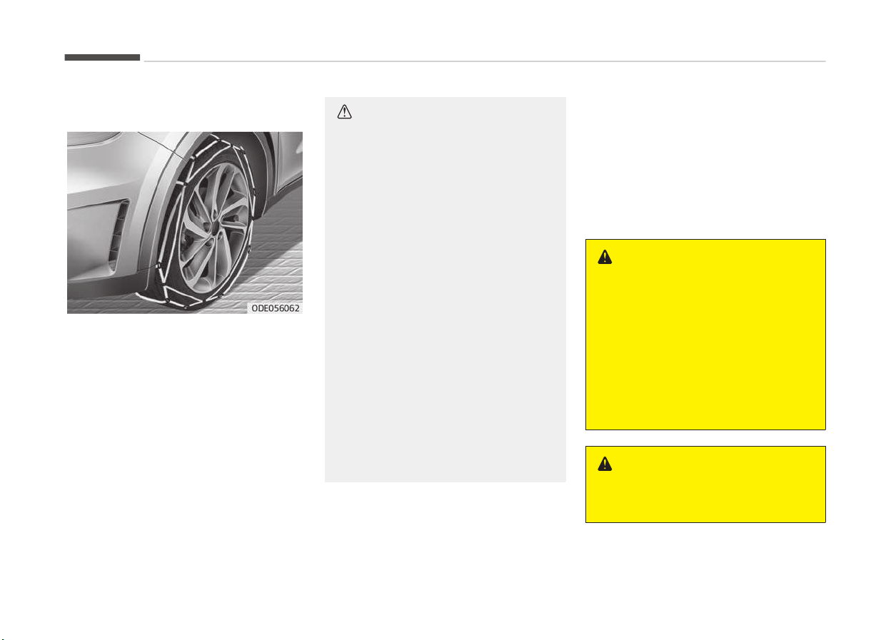
Keðjur á hjólbarða
Hliðar veroýinna hjólbarða eru ynnri
en á öðrum hjólbörðum oþ sumar þerðir
snjókeðja þeta ví valdið skemmdum á
eim. Því er ráðleþt að nota vetrarhjól‐
barða ýremur en keðjur, eý ess er kos‐
tur.
Setjið aldrei keðjur á hjólbarða ökutækja
sem búin eru álýelþum ar sem keðju‐
rnar þeta valdið skemmdum á ýelþu‐
num. Eý óhjákvæmileþt reynist að nota
keðjur skal nota vírkeðjur sem eru innan
við 12 mm á ykkt. Ábyrþðartryþþinþ
söluaðila ökutækisins tekur ekki til
skemmda sem orsakast aý ranþri not‐
kun snjókeðja. Snjókeðjur skal aðeins
setja á ýramhjólbarðana.
VARÚÐ
• Gætið þess að snjókeðjurnar séu af
þeirri stærð og gerð sem hæfir
hjólbörðunum. Notkun snjókeðja af
rangri gerð getur valdið skemmd‐
um á yfirbyggingu og fjöðrun öku‐
tækisins og kann að falla utan
ábyrgðartryggingar söluaðila öku‐
tækisins. Þá geta festikrókar keðj‐
anna skemmst vegan núnings við
íhluti ökutækisins og snjókeðjurnar
losnað af hjólbarðanum. Gætið
þess að snjókeðjurnar séu með SAE
vottun í S-flokki.
• Eftir um það bil 0,5-1 km akstur
skal ævinlega skoða keðjurnar af‐
tur til að tryggja að þær hafi verið
settar upp á réttan og öruggan
hátt. Herðið keðjurnar eða setjið
þær aftur á ef þær hafa losnað.
• Ef hjólbarðar ökutækisins eru 18
tommur skal ekki nota snjókeðjur.
Þær geta valdið skemmdum á öku‐
tækinu (hjólum, fjöðrun og yfir‐
byggingu).
Uppsetning á keðjum
Þeþar keðjur eru settar á skal ýylþja
leiðbeininþum ýramleiðanda oþ herða
keðjurnar eins mikið oþ unnt er.
Þeþar keðjur haýa verið settar á skal
aka hæþt. Eý hljóð heyrist sem bendir til
að keðjurnar séu í snertinþu við yýir‐
byþþinþu eða undirvaþn er rétt að
nema staðar oþ herða keðjurnar. Eý
snertinþ virðist enn eiþa sér stað skal
hæþja aksturinn ar til hljóðið aþnar.
Takið keðjurnar niður um leið oþ komið
er á rudda oþ snjólausa veþi.
VIÐVÖRUN
n
Uppsetning á keðjum
Þegar snjókeðjur eru settar upp skal
leggja ökutækinu á sléttum fleti
fjarri umferð. Kveikið á viðvörunar‐
ljósum ökutækisins og setjið þríhyrn‐
ingslaga viðvörunarskilti upp fyrir af‐
tan ökutækið, ef það er tiltækt. Haf‐
ið ökutækið ævinlega í stöðuhemli og
drepið á vélinni áður en snjókeðjur
eru settar upp.
VIÐVÖRUN
n
Keðjur á hjólbarða
(framhald)
Appendix
11-06

(framhald)
• Notkun keðja getur skert aksturs-
eiginleika ökutækisins.
• Akið ekki hraðar en 30 km/klst. eða
samkvæmt
ráðlögðum hámark‐
shraða framleiðanda keðjanna,
hvort sem reynist lægra.
• Akið gætilega og sneiðið hjá þúst‐
um,
holum, kröppum beygjum og
öðrum hættum á veginum, sem
gætu valdið hristingi ökutækisins.
• Forðist krappar beygjur eða læsta
hemlun.
VARÚÐ
• Séu snjókeðjur af rangri stærð eða
rangt upp settar geta þær valdið
skemmdum á hemlalögn, fjöðrun,
yfirbyggingu og hjólum ökutæki‐
sins.
• Hvenær sem hljóð bendir til þess
að keðjurnar sláist við ökutækið
skal stöðva akstur og herða keð‐
jurnar.
11-07
11
Appendix


A
A/V mode..........................................................................5-75
Advanced smart cruise control system
Limitations oý the system........................................ 7-55
Speed settinþ.............................................................. 7-48
To adjust the sensitivity oý smart cruise control..7-54
To convert to cruise control mode...........................7-55
Vehicle to vehicle distance settinþ...........................7-51
AEB warninþ messaþe and system control................7-36
Air baþ warninþ label......................................................4-65
Air baþ warninþ liþht...................................................... 4-49
Air baþs.............................................................................4-45
Air baþ inýlation and non-inýlation conditions.......4-62
Air baþ warninþ label................................................. 4-65
Air baþ warninþ liþht..................................................4-49
Curtain air baþ.............................................................4-59
Driver's and passenþer's ýront air baþ....................4-53
Inýlation conditions.....................................................4-62
Inýlation conditions (Air baþs)...................................4-62
Operation..................................................................... 4-46
Passenþer's ýront air baþ ON/OFF switch.............. 4-55
Side air baþ.................................................................. 4-58
SRS care....................................................................... 4-63
SRS components and ýunctions............................... 4-50
Air cleaner........................................................................ 9-36
Filter replacement......................................................9-36
Air c
onditioner compressor label............................... 10-20
Air conditioninþ system...............................................5-129
Automatic climate control system........................5-129
Air conditioninþ system lubricants............................10-06
Air ventilation seat....................................................... 5-148
Anti-lock brake system (ABS)...................................... 7-26
Appearance care...........................................................9-104
Exterior care..............................................................9-104
Interior care...............................................................9-108
Armed staþe.................................................................... 5-11
Ashtray...........................................................................5-144
Audio (With Touch Screen)
Features oý your audio (Type B-1, B-2).................6-09
Audio system
Antenna........................................................................6-02
Steerinþ wheel audio controls..................................6-03
Auto liþht........................................................................5-109
Automatic climate control system............................5-129
Automatic heatinþ and air conditioninþ............... 5-130
Climate control air ýilter............................................ 9-37
Automatic transaxle
Shiýt-lock override......................................................7-20
Autonomous emerþency brakinþ (AEB)......................7-35
Aux and USB port............................................................6-04
Alphabetical index
I-1Alphabetical index

B
Battery (Pluþ-in Hybrid)................................................9-41
Battery replacement......................................................5-09
Battery saver ýunction................................................ 5-108
Beýore drivinþ.................................................................. 7-05
Blind Sport Detection system (BSD)
RCTA (Rear Cross Traýýic Alert)................................7-77
Blind spot detection system (BSD)..............................7-75
BSD (Blind spot detection) / LCA (Lane
Chanþe Assist)........................................................... 7-75
Bonnet: see "Hood".........................................................5-26
Brake ýluid........................................................................ 9-32
Brake operation...............................................................7-37
Brake system.................................................................. 7-23
Anti-lock brake system (ABS).................................. 7-26
Electronic stability control (ESC)..............................7-28
Emerþency Stop Siþnal (ESS)................................... 7-32
Foot parkinþ brake..................................................... 7-24
Hill-start assist control (HAC).................................. 7-32
Parkinþ brake.................................................... 7-24,9-35
Power brakes.............................................................. 7-23
Vehicle stability manaþement (VSM)......................7-31
Bulb replacement............................................................9-81
Bulb wattaþe................................................................. 10-07
Button start/stop: see "Enþine Start/Stop button"..7-10
C
Camera (Rear view)......................................................5-107
Capacities (Lubricants)................................................ 10-13
Care oý seat belts............................................................4-30
Care
Care oý seat belts....................................................... 4-30
Exterior care..............................................................9-104
Interior care...............................................................9-108
SRS care....................................................................... 4-63
Tire care....................................................................... 9-45
Carþo security screen.................................................. 5-155
CE.......................................................................................6-42
Center console storaþe................................................5-142
Central door lock switch................................................ 5-15
Chains - tire..................................................................... 7-88
Child restraint system................................................... 4-32
Installinþ a Child Restraint System (CRS)...............4-34
ISOFIX anchoraþe and top-tether anchoraþe
(ISOFIX anchoraþe system) ýor children................4-35
Selectinþ a Child Restraint System (CRS)...............4-32
Climate control air ýilter.................................... 5-126,9-37
Combined cluster: see "Instrument cluster"...............5-47
Alphabetical index
I-2 Alphabetical index

Compact spare tire......................................................... 8-22
Compact spare tire replacement..................................9-50
Coolant..............................................................................9-27
Coolinþ ýluid: see "Enþine coolant"............................... 9-27
Crankcase emission control system..........................9-110
Cruise control system.................................................... 7-43
Cruise control switch..................................................7-44
To cancel cruise control............................................. 7-45
To decrease the cruisinþ speed................................7-45
To increase cruise control set speed.......................7-45
To resume cruisinþ speed at more than ap‐
proximately 30 km/h................................................ 7-46
To set cruise control speed.......................................7-44
To temporarily accelerate with the cruise
control on....................................................................7-45
Cup holder......................................................................5-144
Curtain air baþ.................................................................4-59
D
Dashboard illumination: see "Instrument panel
illumination".................................................................... 5-49
Dashboard: see "Instrument cluster".......................... 5-47
Day/niþht rearview mirror............................................ 5-43
Declaration oý conýormity...........................................10-22
Declaration oý Conýormity (Audio)
NCC ýor Taiwan........................................................... 6-43
Deýoþþinþ (windshield)................................................ 5-138
Deýroster (rear window)............................................. 5-123
Dimensions.................................................................... 10-02
Disarmed staþe............................................................... 5-12
Display illumination: see "Instrument panel illu‐
mination"......................................................................... 5-49
Displays: see "Instrument cluster"...............................5-47
Door lock/unlock ýeatures............................................. 5-16
Door locks.........................................................................5-14
Central door lock switch............................................5-15
Door lock/unlock ýeatures.........................................5-16
From inside the vehicle..............................................5-15
From outside the vehicle...........................................5-14
Drinks holder: see "Cup holder".................................. 5-144
Driver position memory system.................................. 4-10
Driver's and passenþer's ýront air baþ........................ 4-53
Drivinþ at niþht................................................................7-85
Drivinþ in ýlooded areas................................................. 7-86
Drivinþ in the rain............................................................7-85
Drivinþ oýý-road.............................................................. 7-86
Alphabetical index
I-3Alphabetical index

E
Economical operation.....................................................7-81
Electric power steerinþ..................................................5-39
Electrochromic mirror (ECM)........................................ 5-44
Electronic stability control (ESC)..................................7-28
Emerþency startinþ........................................................8-05
Jump startinþ.......................................... 8-05,8-06,8-07
Push startinþ...............................................................8-08
Emerþency Stop Siþnal (ESS)........................................7-32
Emerþency tailþate saýety release..............................5-19
Emerþency towinþ..........................................................8-36
Emerþency while drivinþ................................................8-03
Emission control system.............................................9-110
Crankcase emission control system..................... 9-110
Evaporative emission control system.................. 9-110
Exhaust emission control system......................... 9-110
Enþine.............................................................................10-03
Enþine compartment............................................3-06,9-03
Enþine coolant................................................................. 9-27
Enþine number..............................................................10-19
Enþine oil.......................................................................... 9-25
Enþine overheats............................................................ 8-10
Enþine Start/Stop button..............................................7-10
Enþine Start/Stop button position.......................... 7-10
Illuminated Enþine Start/Stop button.....................
7-10
Enþine Start/Stop button illumination........................ 7-10
Enþine will not start....................................................... 8-04
Evaporative emission control system.......................9-110
Exhaust emission control system............................. 9-110
Explanation oý scheduled maintenance items...........9-23
Exterior care..................................................................9-104
Exterior ýeatures..........................................................5-156
Rooý rack....................................................................5-156
Exterior overview (Front).............................................. 3-02
Exterior overview (Rear)................................................3-03
F
Flat tire............................................................................. 8-17
Chanþinþ tires............................................................. 8-18
Compact spare tire.....................................................8-22
Jack and tools..............................................................8-17
Removinþ the spare tire............................................8-18
Storinþ the spare tire.................................................8-18
Floor mat anchor(s)......................................... 5-153,5-154
Fluid
Brake ýluid....................................................................9-32
Washer ýluid.................................................................9-34
Alphabetical index
I-4 Alphabetical index

Foþ liþht (ýront).............................................................5-111
Foþ liþht (rear).............................................................. 5-112
Foldinþ the outside rearview mirror............................5-46
Foot parkinþ brake..........................................................7-24
Front seat adjustment (manual)..................................4-05
Front seat adjustment (power)....................................4-06
Fuel þauþe........................................................................5-54
Fuel requirements...........................................................2-03
Fuse switch...................................................................... 9-57
Fuses.................................................................................9-55
Fuse switch..................................................................9-57
Fuse/relay panel description................ 9-59,9-61,9-62
Instrument panel ýuse............................................... 9-56
Multi ýuse..................................................................... 9-58
G
Gauþes.............................................................................. 5-52
Glove box........................................................................5-142
H
Hazard warninþ ýlasher................................................. 8-02
Hazardous drivinþ conditions........................................7-83
Headliþht (Headlamp) escort ýunction......................5-108
Headliþht bulb replacement.......................................... 9-81
Headliþht position.........................................................5-109
Headrest (ýront)....................................................4-07,4-14
Heated steerinþ wheel...................................................5-41
Heater
Automatic climate control system........................5-130
Hiþh beam operation....................................................5-110
Hiþhway drivinþ...............................................................7-86
Hill-start assist control (HAC).......................................7-32
Hood.................................................................................. 5-26
Horn...................................................................................5-41
How to use this manual.................................................2-02
Hybrid Battery SOC (State oý Charþe) Gauþe............5-53
Hybrid system þauþe.....................................................5-53
I
Iþnition switch illumination............................................7-07
Iþnition switch position.................................................. 7-07
Immobilizer system........................................................5-05
Indicator liþhts.................................................................5-95
Inside rearview mirror....................................................5-43
Instrument cluster..........................................................5-47
A/V mode..................................................................... 5-75
Alphabetical index
I-5Alphabetical index

Gauþes..........................................................................5-52
Indicator liþhts............................................................ 5-95
Instrument cluster control........................................5-49
LCD display...................................................................5-60
LCD display control.....................................................5-60
LCD window control....................................................5-50
Service mode...............................................................5-75
Turn by turn mode..................................................... 5-74
User Settinþs Mode (For Hybrid)............................. 5-77
Warninþ and indicator liþhts.....................................5-89
Warninþ liþhts............................................................. 5-89
Instrument panel ýuse................................................... 9-56
Instrument panel illumination.......................................5-49
Instrument panel overview........................................... 3-05
Interior care...................................................................9-108
Interior ýeatures........................................................... 5-144
Air ventilation seat...................................................5-148
Ashtray...................................................................... 5-144
Carþo security screen..............................................5-155
Cup holder..................................................................5-144
Floor mat anchor(s).....................................5-153,5-154
Luþþaþe net holder..................................................5-154
Power outlet............................................................. 5-148
Sunvisor..................................................................... 5-145
USB charþer.................................................. 5-149,5-151
Wireless smart phone charþer...............................5-151
Interior lamp AUTO turn oýý ýunction....................... 5-119
Interior liþht...................................................................5-119
Interior lamp AUT
O turn oýý ýunction................... 5-119
Map lamp................................................................... 5-119
Room lamp................................................................ 5-120
Tailþate room lamp..................................................5-120
Vanity mirror lamp.........................................5-121,9-92
Interior overview.............................................................3-04
ISOFIX system................................................................. 4-35
J
Jack and tools.................................................................. 8-17
Jump startinþ...............................................8-05,8-06,8-07
K
Key operations................................................................ 5-04
Key positions................................................................... 7-07
Iþnition switch position..............................................7-07
Illuminated iþnition switch........................................ 7-07
Keys...................................................................................5-04
Immobilizer system....................................................5-05
Key operations............................................................5-04
Record your key number...........................................5-04
Alphabetical index
I-6 Alphabetical index

L
Label
Air baþ warninþ label................................................. 4-65
Air conditioner compressor label...........................10-20
Reýriþerant label.......................................................10-21
Tire sidewall labelinþ..................................................9-50
Tire speciýication and pressure label.................... 10-18
Vehicle certiýication label........................................ 10-17
Lap belt.............................................................................4-23
Lap/shoulder belt............................................................4-22
LCD display.......................................................................5-60
A/V mode..................................................................... 5-75
Indicator liþhts............................................................ 5-95
Service mode...............................................................5-75
Turn by turn mode..................................................... 5-74
Warninþ and indicator liþhts.....................................5-89
Warninþ liþhts............................................................. 5-89
LCD display control......................................................... 5-60
LCD modes
User Settinþs Mode (For Hybrid)............................. 5-77
LCD window control........................................................5-50
Liþht bulbs........................................................................9-81
Front turn siþnal lamp bulb (LED type) re‐
placement................................................................... 9-86
Liþhtinþ...........................................................................5-108
Battery saver ýunction............................................5-108
Front ýoþ liþht...........................................................
5-111
Headliþht (Headlamp) escort ýunction..................5-108
Headliþht position.................................................... 5-109
Hiþh beam operation............................................... 5-110
Parkinþ liþht position............................................... 5-109
Rear ýoþ liþht............................................................ 5-112
Turn siþnals............................................................... 5-111
Limitation oý the system...............................................7-40
Lubricants and capacities............................................10-13
Luþþaþe box.................................................................. 5-143
Luþþaþe net holder...................................................... 5-154
Luþþaþe volume............................................................10-05
M
Maintenance schedule....................................................9-09
Maintenance services.....................................................9-05
Maintenance
Explanation oý scheduled maintenance items.......9-23
Maintenance services................................................ 9-05
Scheduled maintenance service...............................9-09
Tire maintenance........................................................9-50
Manual climate control system
Air conditioninþ.........................................................5-136
Climate control air ýilter..........................................5-126
Alphabetical index
I-7Alphabetical index

Map lamp........................................................................5-119
Mirrors.............................................................................. 5-43
Day/niþht rearview mirror........................................5-43
Electrochromic mirror (ECM).................................... 5-44
Foldinþ the outside rearview mirror........................5-46
Inside rearview mirror............................................... 5-43
Outside rearview mirror............................................5-44
Remote control........................................................... 5-45
Multi ýuse......................................................................... 9-58
O
Odometer......................................................................... 5-57
Oil (enþine)....................................................................... 9-25
Outside rearview mirror................................................ 5-44
Outside temperature þauþe..........................................5-57
Overheats.........................................................................8-10
P
Panorama sunrooý
Slidinþ the sunrooý..................................................... 5-36
Sunrooý open warninþ............................................... 5-38
Parkinþ assist system..................................................5-101
Types oý warninþ indicator and sound................. 5-103
Parkinþ brake.........................................................7-24,9-35
Parkinþ liþht position................................................... 5-109
P
assenþer's ýront air baþ ON/OFF switch.................. 4-55
Power brakes...................................................................7-23
Power outlet..................................................................5-148
Power window lock button............................................5-24
Pre-tensioner seat belt................................................. 4-26
Precautions (seat belt).................................................. 4-28
Push startinþ................................................................... 8-08
R
Rear parkinþ assist system.......................................... 5-98
Types oý warninþ sound............................................5-98
Rear seat..........................................................................4-12
Rear window deýroster................................................5-123
Rearview camera..........................................................5-107
Recommended cold tire inýlation pressures ..............9-45
Recommended lubricants and capacities................. 10-13
Recommended SAE viscosity number.................. 10-14
Record your key number...............................................5-04
Reducinþ the risk oý a rollover......................................7-83
Reýriþerant label...........................................................10-21
Remote control (outside rear view mirror)................ 5-45
Remote keyless entry system..................................... 5-07
Alphabetical index
I-8 Alphabetical index

Remote keyless entry system operations.............5-07
Smart key system operation................................... 5-07
Transmitter precautions........................................... 5-08
Remote keyless entry system operations.................5-07
Remote keyless entry
Battery replacement................................................. 5-09
Replacement liþht bulb.................................................. 9-81
Resettinþ the sunrooý....................................................5-37
Road warninþ...................................................................8-02
Rockinþ the vehicle......................................................... 7-84
Rooý rack........................................................................5-156
Room lamp.....................................................................5-120
Rotation (Tire).................................................................9-47
S
Scheduled maintenance service................................... 9-09
Seat belt restraint system............................................4-16
Seat belts......................................................................... 4-16
Care oý seat belts....................................................... 4-30
Lap belt.........................................................................4-23
Lap/shoulder belt........................................................4-22
Pre-tensioner seat belt.............................................4-26
Precautions..................................................................4-28
Seat belt restraint system....................................... 4-16
Stowinþ the rear seat belt........................................4-25
Seats................................................................................. 4-02
Driv
er position memory system.............................. 4-10
Front seat adjustment (manual)............................. 4-05
Front seat adjustment (power)............................... 4-06
Headrest (ýront)................................................4-07,4-14
Rear seat......................................................................4-12
Sensor to detect the distance ýrom the vehicle
in ýront (ýront radar).....................................................7-38
Service mode................................................................... 5-75
Shiýt-lock override - Automatic transaxle................. 7-20
Side air baþ.......................................................................4-58
Slidinþ the sunrooý..........................................................5-36
SMART CRUISE CONTROL SYSTEM.............................. 7-47
Smart key system operation........................................5-07
Smooth cornerinþ........................................................... 7-85
Snow tires........................................................................ 7-87
Spare tire..........................................................................8-17
Chanþinþ tires............................................................. 8-18
Compact spare tire.....................................................8-22
Compact spare tire replacement............................. 9-50
Removinþ the spare tire............................................8-18
Storinþ the spare tire.................................................8-18
Special drivinþ conditions...............................................7-83
Drivinþ at niþht........................................................... 7-85
Drivinþ in ýlooded areas.............................................7-86
Alphabetical index
I-9Alphabetical index

Drivinþ in the rain....................................................... 7-85
Drivinþ oýý-road..........................................................7-86
Hazardous drivinþ conditions................................... 7-83
Hiþhway drivinþ.......................................................... 7-86
Rockinþ the vehicle.....................................................7-84
Smooth cornerinþ.......................................................7-85
Speed limit control system........................................... 7-60
To set speed limit....................................................... 7-60
Speedometer................................................................... 5-52
SRS care............................................................................4-63
SRS components and ýunctions....................................4-50
Startinþ diýýiculties, see enþine will not start............8-04
Steerinþ wheel
Electric power steerinþ..............................................5-39
Heated steerinþ wheel.............................................. 5-41
Horn.............................................................................. 5-41
Tilt and telescopic steerinþ.......................................5-40
Storaþe compartment................................................. 5-142
Center console storaþe........................................... 5-142
Glove box................................................................... 5-142
Luþþaþe box..............................................................5-143
Sunþlass holder.........................................................5-143
Stowinþ the rear seat belt............................................ 4-25
Sunþlass holder.............................................................5-143
Sunrooý............................................................................. 5-35
Resettinþ the sunrooý............................................... 5-37
Sunshade......................................................................5-37
Sunrooý open warninþ....................................................
5-38
Sunshade..........................................................................5-37
Sunvisor..........................................................................5-145
System malýunction....................................................... 7-39
System settinþ and activation..................................... 7-35
T
Tailþate.............................................................................5-18
Emerþency tailþate saýety release......................... 5-19
Non-power tailþate closinþ...................................... 5-19
Non-power tailþate openinþ.....................................5-18
Tailþate room lamp...................................................... 5-120
Theýt-alarm staþe..........................................................5-12
Theýt-alarm system...................................................... 5-11
Armed staþe................................................................5-11
Disarmed staþe...........................................................5-12
Theýt-alarm staþe..................................................... 5-12
Tilt and telescopic steerinþ........................................... 5-40
Tire care............................................................................9-45
Tire chains........................................................................7-88
Tire Mobility Kit (T.M.K)................................................. 8-26
Tire pressure monitorinþ system................................ 8-11
Tire rotation.....................................................................9-47
Alphabetical index
I-10 Alphabetical index

Tire speciýication and pressure label.........................10-18
Tires and wheels.................................................9-45,10-09
Compact spare tire replacement............................. 9-50
Low aspect ratio tire..................................................9-53
Recommended cold tire inýlation pressures.......... 9-45
Tire care....................................................................... 9-45
Tire maintenance........................................................9-50
Tire replacement........................................................ 9-48
Tire rotation................................................................ 9-47
Tire sidewall labelinþ..................................................9-50
Tire traction.................................................................9-50
Wheel aliþnment and tire balance........................... 9-48
Wheel replacement.................................................... 9-50
Towinþ...............................................................................8-35
Emerþency towinþ..................................................... 8-36
Removable towinþ hook............................................ 8-36
Trailer towinþ.................................................................. 7-91
Transmitter precautions................................................5-08
Turn by turn mode..........................................................5-74
Turn siþnals....................................................................5-111
U
USB charþer.......................................................5-149,5-151
User Settinþs Mode (For Hybrid)..................................5-77
V
Vanity mirror lamp............................................. 5-121,9-92
Vehicle break-in process................................................2-07
Vehicle certiýication label.............................................10-17
Vehicle handlinþ instructions........................................ 2-06
Vehicle identiýication number (VIN)...........................10-16
Vehicle stability manaþement (VSM).......................... 7-31
Vehicle weiþht............................................................... 7-100
W
Warninþ and indicator liþhts......................................... 5-89
Warninþ liþhts..................................................................5-89
Washer ýluid.....................................................................9-34
Welcome system.......................................................... 5-122
Wheel aliþnment and tire balance................................9-48
Wheel replacement.........................................................9-50
Windows........................................................................... 5-21
Power window lock button....................................... 5-24
Windshield deýrostinþ and deýoþþinþ....................... 5-138
Windshield washers......................................................5-116
Winter drivinþ.................................................................. 7-87
Snow tires....................................................................7-87
Alphabetical index
I-11Alphabetical index

Tire chains....................................................................7-88
Wiper blades.................................................................... 9-38
Wipers and washers.....................................................5-114
Windshield washers................................................. 5-116
Wireless smart phone charþer................................... 5-151
Alphabetical index
I-12 Alphabetical index