File:01fnpic.ex
Update:Thu Jun 20 15:18:28 1996

i
Table of Contents
File:01fnpic.ex
Update:Thu Jun 20 15:18:28 1996

ii
File:01fnpic.ex
Update:Thu Jun 20 15:18:28 1996

iii
File:01fnpic.ex
Update:Thu Jun 20 15:18:28 1996

iv
File:01fnpic.ex
Update:Thu Jun 20 15:18:28 1996

1
Introduction
Ford’s Commitment to You
At Ford Motor Company, excellence is the
continuous commitment to achieve the best result
possible. It is dedication to learning what you want,
determination to develop the right concept, and
execution of that concept with care, precision, and
attention to detail. In short, excellence means being
the standard by which others are judged.
Our Guiding Principles
❑
Quality comes first. For your satisfaction, the
quality of our products and services must be our
number one priority.
❑
You are the focus of everything we do. Our
work must be done with you in mind,
providing better products and services than our
competition.
❑
Continuous improvement is essential to our
success. We must strive for excellence in
everything we do: in our products — in their
safety and value — and in our services, our
human relations, our competitiveness, and our
profitability.
❑
Employee involvement is our way of life.
We are a team. We must treat one another
with trust and respect.
❑
Dealers and suppliers are our partners. We
must maintain mutually beneficial relationships
with dealers, suppliers, and our other business
associates.
❑
Integrity is never compromised. Our conduct
worldwide must be pursued in a manner that is
socially responsible and commands respect for
its integrity and for its positive contributions to
society.
File:02fniic.ex
Update:Mon Jun 17 14:13:47 1996
2
ThingstoKnowAboutUsingThis
Guide
Congratulationsonthepurchaseofyournew
vehicle.Thisguidehasinformationaboutthe
equipmentandtheoptionsforyournewvehicle.
Youmaynothaveboughtalloftheoptions
availabletoyou.Ifyoudonotknowwhich
informationappliestoyourvehicle,talktoyour
dealer.
Thisguidedescribesequipmentandgives
specificationsforequipmentthatwasineffectwhen
thisguidewasapprovedforprinting.Fordmay
discontinuemodelsorchangespecificationsor
designwithoutanynoticeandwithoutincurring
obligation.
NOTESandWARNINGS
NOTESgiveyouadditionalinformationaboutthe
subjectmatteryouarereferencing.
WARNINGSremindyoutobeespeciallycarefulin
thoseareaswherecarelessnesscancausedamageto
yourvehicleorpersonalinjurytoyourself,your
passengersorotherpeople.Pleasereadall
WARNINGScarefully.
WARNING
File:02fniic.ex
Update:Mon Jun 17 14:13:47 1996

3
Finding Information in This Guide
After you have read this guide once, you will
probably return to it when you have a specific
question or need additional information. To help
you find specific information quickly, you can use
the Quick Index or the Index.
The Quick Index at the end of the book provides
a page number following each item which indicates
where detailed information can be found.
To use the Index, turn to the back of the book
and search in the alphabetical listing for the word
that best describes the information you need. If the
word you chose is not listed, think of other related
words and look them up. We have designed the
Index so that you can find information under a
technical term.
Canadian Owners — French Version
French Owner Guides can be obtained from your
dealer or by writing to Ford Motor Company of
Canada, Limited, Service Publications, P.O. Box
1580, Station B, Mississauga, Ontario L4Y 4G3.
The Lincoln Commitment
The Lincoln Commitment is more than the prestige
of owning a superior luxury automobile, it is a
comprehensive owner benefits package that is
designed to provide you with services to support
your every driving need. Refer to the Lincoln
Commitment brochure for more information.
Your Maintenance Schedule and
Record Booklet
The Maintenance Schedule booklet lists the services
that are most important for keeping your vehicle in
good condition. A record log is also provided to
help you keep track of all services performed.
File:02fniic.ex
Update:Mon Jun 17 14:13:47 1996

4
About the Warranties
Your vehicle is covered by three types of warranties:
Basic Vehicle Warranty, Extended Warranties
on certain parts, and Emissions Warranties.
Read your Warranty Information Booklet carefully to
find out about your vehicle’s warranties and your
basic rights and responsibilities.
If you lose your Warranty Information Booklet, you
can get a new one free of charge. Contact any Ford
or Lincoln-Mercury dealer, or refer to the addresses
and phone numbers on the first page of this
Owner’s Guide.
More Protection for Your Vehicle
You can get more protection for your new car or
light truck by purchasing a Ford Extended Service
Plan (Ford ESP). Ford ESP is the only extended
service program with the Ford name on it and the
only service contract backed by Ford Motor
Company.
Ford ESP is an optional service contract, backed and
administered by Ford. It provides:
❑
protection against repair costs after your Bumper
to Bumper Warranty expires;
and
❑
other benefits during the warranty period (such
as: reimbursement for rentals; coverage for
certain maintenance and wear items).
You may purchase Ford ESP from any participating
Ford Motor Company dealer. There are several Ford
ESP plans available in various time-and-mileage
combinations. Each plan can be tailored to fit your
own driving needs, including reimbursement
benefits for towing and rental. (In Hawaii, rules
vary. See your dealer for details.)
File:02fniic.ex
Update:Mon Jun 17 14:13:47 1996

5
When you buy Ford ESP, you receive peace-of-mind
protection throughout the United States and
Canada, provided by a network of more than 5,100
participating Ford Motor Company dealers.
NOTE: Repairs performed outside the United States
and Canada are not eligible for ESP coverage.
This information is subject to change. Ask your
dealer for complete details about Ford ESP coverage.
Breaking Your Vehicle In
Your new vehicle goes through an adjustment or
break-in period during the first 1,000 miles
(1,600 km) that you drive it. During the break-in
period, you need to pay careful attention to how
you drive your vehicle.
❑
Avoid sudden stops. Because your vehicle has
new brake linings, you should take these steps:
—Watch traffic carefully so that you can
anticipate when to stop.
—Begin braking well in advance.
—Apply the brakes gradually.
The break-in period for new brake linings
lasts for 100 miles (160 km) of city driving
or 1,000 miles (1,600 km) of highway
driving.
❑
Use only the type of engine oil that Ford
recommends. See Engine oil recommendations
in the Index. Do not use special “break-in” oils.
File:02fniic.ex
Update:Mon Jun 17 14:13:47 1996

7
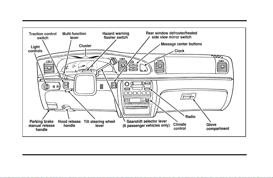
Instrumentation
The instrument panel (dashboard) on your vehicle is
divided into several different sections. The
illustrations on the following pages show the major
parts of the instrument panel that are described in
this chapter. Some items shown may not be on all
vehicles.
The main controls for the climate control system,
clock, and radio are on the instrument panel.
If you have radio transmitting equipment in your
vehicle, be aware that it can interfere with your
vehicle’s electrical system and may cause the
instrumentation and/or convenience products to
have temporary, abnormal operation.
NOTE: Any cleaner or polish that increases the
gloss (shine) of the upper part of the instrument
panel should be avoided. The dull finish in this area
is to help protect the driver from undesirable
windshield reflection.
File:03fnisc.ex
Update:Mon Jun 17 14:14:40 1996
8
Instrument panel
File:03fnisc.ex
Update:Mon Jun 17 14:14:40 1996
9
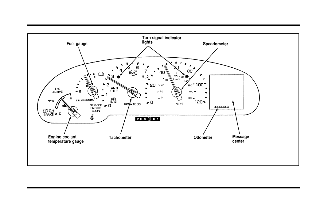
Instrument cluster
File:03fnisc.ex
Update:Mon Jun 17 14:14:40 1996
10
The following warning lights and gauges are on the
instrument cluster. All of the warning lights and
gauges alert you to possible problems with your
vehicle.
Indicator Lights and Chimes
Safety Belt Warning Light and Chime
This warning light and chime remind you to fasten
your safety belt. The following conditions will take
place:
❑
If the safety belt is not buckled when the
ignition is turned to the ON position, the chime
will turn on for four (4) to eight (8) seconds
and the light will come on for one to two
minutes.
❑
If the safety belt is buckled while the light is on
and the chime is sounding, both the light and
chime will turn off.
❑
If the safety belt is buckled before the ignition
is turned to the ON position, neither the light
nor the chime will come on.
Brake System Warning Light
The warning light for the brakes can show two
things — that the parking brake is not fully
released, or that the brake fluid level is low in the
master cylinder reservoir. If the fluid level is low,
the brake system should be checked by your dealer
or a qualified service technician.
File:03fnisc.ex
Update:Mon Jun 17 14:14:40 1996
11
Thislightcomesonwhentheparkingbrakeisset,
orifitisnotset,itcomesonbrieflywhenyou
turntheignitiontotheSTARTposition.Itnormally
goesoffshortlyaftertheenginestartsandyou
releasetheparkingbrake.Ifthelightstaysonafter
youhavefullyreleasedtheparkingbrake,havethe
hydraulicbrakesystemservicedbyyourdealerora
qualifiedservicetechnician.
WARNING
TheBRAKElightindicatesthatthe
brakesmaynotbeworkingproperly.
Havethebrakescheckedimmediately.
Anti-LockBrakeSystemWarningLight
Thislightcomesonforafewsecondswhenyou
turntheignitionkeytotheSTARTposition.It
shouldgooffshortlyaftertheenginestarts.Ifit
staysonlongerthanfive(5)seconds,itindicates
thatyouranti-lockbrakesystemmaynotbe
workingproperly.Normalbrakingisnotaffected
unlesstheBRAKEsystemwarninglightalsoremains
onforlongerthansix(6)seconds.Youshouldhave
yourvehicleservicedimmediatelybyyourdealeror
qualifiedservicetechniciantorestorethebenefitsof
theanti-lockfeature.SeeAnti-lockbrakesinthe
Indexformoreinformation.
File:03fnisc.ex
Update:Mon Jun 17 14:14:40 1996
12
Engine Oil Pressure Warning Light
This light indicates the engine’s oil pressure, not the
oil level. However, if your engine’s oil level is low,
it could affect the oil pressure. The light will come
on briefly when you turn your key to the START
and ON position. The light should stay off when
the engine is running with normal oil pressure. If
the light comes on while the engine is running, you
have lost oil pressure and continued operation will
cause severe engine damage.
If you lose engine oil pressure:
1. Pull off the road as soon as safely possible.
2. Shut off the engine immediately or severe
engine damage could result.
3. Check the engine’s oil level, following the
instructions on checking and adding engine oil,
see Engine Oil in the Index. If you do not
follow these instructions, you or others could
be injured. To assure an accurate reading, your
car should be on level ground.
4. If the level is low, add only as much oil as
necessary before you start the engine again. Do
not overfill. Do not operate the engine if the
light is on, regardless of the oil level. Contact
your nearest dealer for further service actions.
For more information about adding oil, see Adding
engine oil in the Maintenance and Care chapter.
File:03fnisc.ex
Update:Mon Jun 17 14:14:40 1996
13
Traction ControlH Active Light
(If equipped)
This light comes on when the Traction ControlH
system begins applying and releasing the brakes and
adjusting the engine characteristics to limit a
wheelspin condition.
It will be lit for a minimum of six seconds or for
the duration of the Traction ControlH event.
Charging System Light
This light indicates that your battery is not being
charged and that you need to have the electrical
system checked.
File:03fnisc.ex
Update:Mon Jun 17 14:14:40 1996
14
This light illuminates every time you turn the
ignition to the ON or START position (engine off).
The light should go off when the engine starts and
the alternator begins to charge.
If the light stays on or illuminates when the engine
is running, have the electrical system checked as
soon as possible.
Turn Signal Indicator Lights
When you push the turn signal lever up before
making a right turn, the right side arrow on the
instrument panel flashes.
When you push the turn signal lever down before
making a left turn, the left side arrow on the
instrument panel flashes.
Usually, the turn signals turn off automatically after
you turn your vehicle. If the turn signal continues
to flash after you have made the turn, push the
lever back to the OFF position.
If one or both of your turn indicators do not flash
or stay on continuously, have them serviced as soon
as possible. In the meantime, be sure to use the
accepted hand signals.
Service Engine Soon Warning Light
This light illuminates when the engine’s Emission
Control System requires service. It will also
illuminate when the ignition key is in the ON
position and the engine is off.
File:03fnisc.ex
Update:Mon Jun 17 14:14:40 1996

15
High Beam Light
This light illuminates when the headlamps are
turned to high beam or when you flash the lights.
Chime for Headlamps On
This chime sounds if the driver or any passenger
door is open when the parking lamps or headlamps
are on. The chime sounds until you close the door,
turn off the lamps or turn the ignition to the ON
position.
Air Bag Readiness Light
The air bag system uses a readiness light and a tone
to indicate the condition of the system. The
readiness light is in the instrument cluster. When
you turn the ignition key to the ON position, this
light will light up for six (6) seconds and then turn
off. This indicates that the system is operating
normally. NOTE: Regularly scheduled maintenance
of the air bag system is not required.
File:03fnisc.ex
Update:Mon Jun 17 14:14:40 1996
16
If the light fails to illuminate, continues to flash,
remains on, or you hear a beeping sound, have the
system serviced at your Ford or Lincoln-Mercury
dealer immediately.
Anti-Theft Alarm Light (If equipped)
This light flashes on and off when the ignition is
turned to the OFF position and any door is opened.
As soon as you lock the doors, the light glows
steadily. Within 30 seconds of closing all the doors,
the light goes out. This indicates that the alarm
system is armed.
See Anti-Theft System in the Controls and Features
chapter for more information.
The Instrument Cluster
In addition to warning lights, the instrument cluster
has a message center/odometer, a speedometer,
tachometer, fuel and coolant temperature gauges.
File:03fnisc.ex
Update:Mon Jun 17 14:14:40 1996

17
Odometer
The odometer tells you the total number of miles
(kilometers) your vehicle has been driven.
If the odometer displays the word Error, please
contact your dealer for service.
Speedometer
The speedometer tells you how many miles
(kilometers) per hour your vehicle is moving.
Tachometer
The tachometer displays the approximate engine
revolutions per minute (rpm), or how fast the
engine is running.
You can drive your vehicle at most rpm points on
the tachometer but you must stay out of the red
zone.
If you drive with the tachometer in the red zone,
you may damage the engine.
Engine Coolant Temperature Gauge
This gauge indicates the temperature of the engine
coolant, not the coolant level. If the coolant is not
at its proper level or mixture, the gauge indication
will not be accurate.
The pointer moves from the C (cold) mark into the
NORMAL band as the engine coolant warms up. It
is acceptable for the pointer to fluctuate within the
NORMAL band under normal driving conditions.
Under certain driving conditions such as, heavy stop
and go traffic, or driving up hills in hot weather,
the pointer may indicate at the top of the NORMAL
band.
If, under any circumstances, the pointer moves
above the NORMAL band, the engine is overheating
and continued operation may cause engine damage.
If your engine overheats:
1. Pull off the road as soon as it is safely possible.
2. Turn off the engine.
File:03fnisc.ex
Update:Mon Jun 17 14:14:40 1996

18
3. Let the engine cool. DO NOT REMOVE
COOLANT SYSTEM FILL CAP UNTIL THE
ENGINE IS COOL.
4. Check the coolant level following the
instructions on checking and adding coolant to
your engine, see Engine Coolant in the Index.
If you do not follow these instructions, you or
others could be injured.
If the coolant continues to overheat, have the
coolant system serviced as soon as possible.
Fuel Gauge
The fuel gauge displays approximately how much
fuel you have in the fuel tank. The ignition switch
must be in the OFF position while filling the tank
with at least three gallons (11 liters) for the fuel
gauge to indicate the new level. If the ignition is
left ON or less than 3 gallons (11 liters) of fuel are
added the fuel gauge will not immediately indicate
the new fuel level. The gauge will gradually correct
itself to indicate the true fuel level.
The Electronic Message Center
(M/C)
The Electronic Message Center only works when
the ignition is in the ON position.
Each time the M/C is powered the display goes
through a self test by displaying the PLEASE
FASTEN SEATBELT message. This self test is used
to stabilize the systems before reporting the status
to you.
The message center tells you about the condition of
your vehicle by two methods:
❑
operator selectable features
❑
continuous warning reporting of monitored
systems
File:03fnisc.ex
Update:Mon Jun 17 14:14:40 1996
19
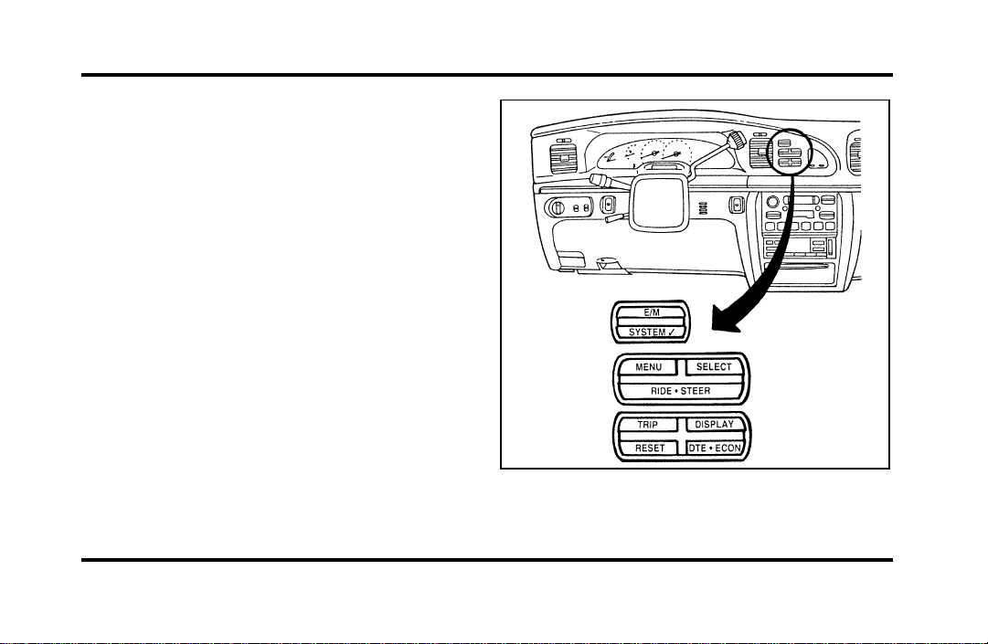
You can select different features for the M/C to
display by using the message center control buttons
located to the right of the instrument cluster. You
will hear a tone when you press one of these
buttons. However, if the M/C detects a warning
from any of the monitored systems, then the M/C
will display the appropriate warning message.
Operator Selectable Features
Cluster Control Buttons and Message Center
Control Buttons
File:03fnisc.ex
Update:Mon Jun 17 14:14:40 1996

20
These features are controlled by the message center
(M/C) control buttons located to the right of the
instrument cluster.
System Check
Pressing the SYSTEM CHECK button causes the
M/C to cycle through a status of each of the
systems being monitored. For each of the monitored
systems, the M/C will indicate either an OK
message or a warning message for three seconds.
The sequence of the system check report is as
follows:
❑
Washer Fluid Level
❑
Ride Control
❑
Oil Level
❑
Engine Coolant Level
❑
Voltage Level
❑
Engine Temperature
❑
Doors Closed (Driver and Right Side)
❑
Trunk Closed
❑
Exterior Lamps (Head, Front Turn, Brake and
Tail)
❑
Distance to Empty
❑
Fuel Level
❑
Traction Control (if equipped)
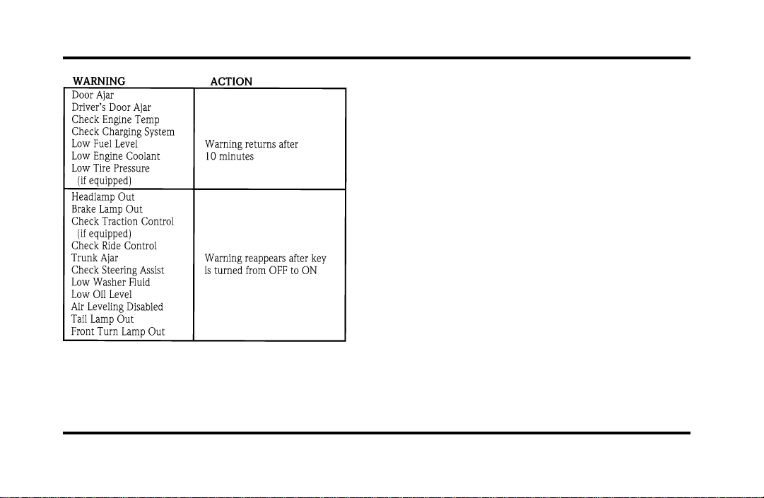
System Warnings
System warnings alert you to possible problems or
malfunctions in your vehicle’s operating systems.
There are up to 18 warning messages which can be
displayed by the M/C to show the status of the
monitored systems. The M/C will display the last
selected feature if there are no more warning
messages. This allows you to use the full
functionality of the M/C after you acknowledge the
warning by pressing the RESET button and clearing
the warning message.
File:03fnisc.ex
Update:Mon Jun 17 14:14:40 1996
21
Warning messages that have been reset are divided
into two categories. They will reappear on the
display ten minutes from the reset or they will not
reappear until an ignition OFF-ON cycle has been
completed. This reappearing of warning messages is
a reminder that these warning conditions still exist
within the vehicle.
E/M
A press of this button allows you to change the
M/C and the Electronic Climate control unit from
English to Metric Units. When you press this button
all displays change from English to Metric or Metric
to English units. The displays remain in the units
you have chosen until you change them again even
after you turn off the vehicle and start it again.
TRIP
Pressing this button will display the first of two trip
odometers. Pressing it again will display the second
Trip Odometer. Pressing RESET will clear ony that
Trip odometer which is displayed.
File:03fnisc.ex
Update:Mon Jun 17 14:14:40 1996

22
DTE/ECON
Pressing this button a first time will display
approximately how many miles you can drive before
you run out of fuel, or in other words the Distance
To Empty (DTE). To ensure accuracy, turn the
ignition OFF when you fill the tank.
Pressing this button a second time will allow you to
display your Average Fuel Economy in miles/gallon
or liters/100 kilometers. Your M/C computes this
figure using the distance traveled and rate of fuel
used information. If you want to reset this feature,
press the RESET button while the Average Fuel
Economy feature is displayed.
NOTE: DTE (Distance to Empty) is calculated using
a “Running Average Fuel Economy” initialized by
the factory. This value is not the same as the
Average Fuel Economy Display. The Running
Average Economy is based on more than 500 miles
(800 km) of driving history. Also the factory default
for Running Average Economy is reinitialized if the
battery is disconnected.
If the FUEL LEVEL ERROR message is displayed
this means that there is a problem with the fuel
indication system and you should contact your
dealer for service as soon as possible.
RESET
A press of the RESET button will allow you to reset
the current feature displayed. Warnings, Average
Fuel Economy, and Trip odometers are the only
features which respond to the RESET button.
Distance to Empty (DTE), RIDE/STEER and MENU
are unaffected by pressing the RESET switch.
DISPLAY
Pressing this button will cause the message center
display to turn off. Pressing it again will cause the
display to come on again. Warnings override an off
display and must be reset in order for the display to
be off again.
File:03fnisc.ex
Update:Mon Jun 17 14:14:40 1996

23
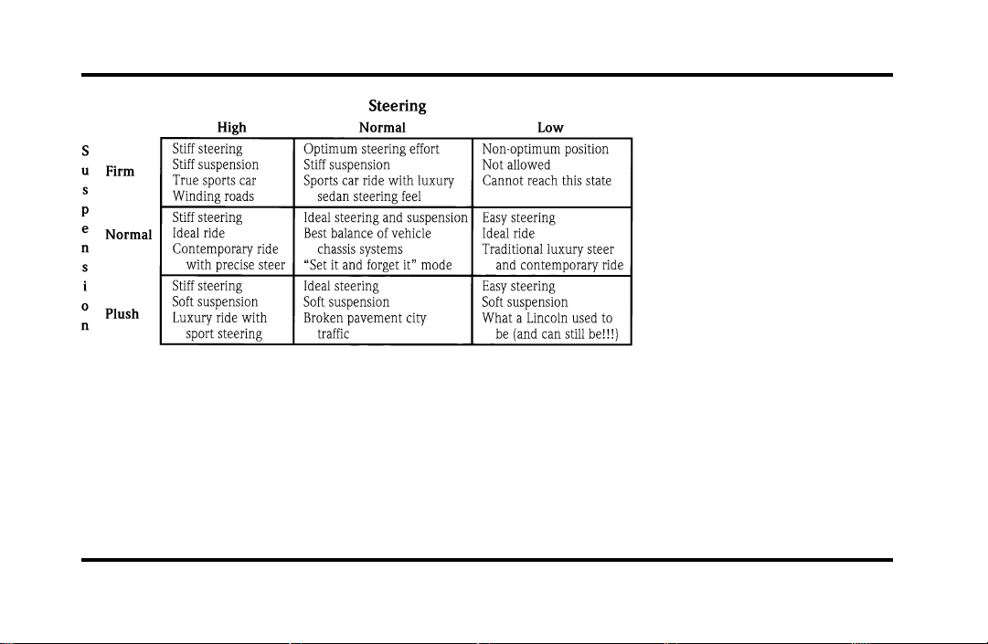
RIDE/STEER
Pressing this button once will allow you to adjust
your RIDE CONTROL settings, between NORMAL,
PLUSH and FIRM. The settings are changed by
pressing the SELECT button while RIDE CONTROL
is displayed.
Pressing the RIDE/STEER button a second time will
allow you to adjust the STEERING EFFORT settings
between NORMAL, LOW, and HIGH. The settings
are changed by pressing the SELECT button while
STEERING EFFORT is displayed.
NOTE: The combination of FIRM RIDE CONTROL
and LOW STEERING EFFORT is undesirable and
cannot be selected.
MENU
Pressing this button will allow you to change
various convenience settings throughout the vehicle.
The settings for each feature are changed by
pressing the SELECT button.
Pressing the MENU button once will allow you to
enable or disable the EXPRESS WINDOW feature.
This feature allows one tap down operation on the
driver’s window using the window switch on the
driver’s door armrest.
Pressing MENU again will allow you to enable or
disable the AUTO DOOR LOCK feature. This
feature automatically locks all doors when the driver
shifts out of PARK, all doors are closed, the driver’s
seat is occupied, and the vehicle is traveling over
three mph (5 km/h).
File:03fnisc.ex
Update:Mon Jun 17 14:14:40 1996

24
Pressing MENU again will allow you to enable or
disable the HORN CHIRP feature. When HORN
CHIRP is ON the horn will briefly sound when the
Remote Entry Key Fob LOCK button is pressed.
This verifies the doors have been locked and the
ANTI-THEFT system has been armed (if equipped).
Pressing MENU again will allow you to enable or
disable the SEAT ACCESS feature. When ON, the
driver’s seat will move back 2 inches (5 cm) or to
end of seat travel when the vehicle is turned off
and the ignition key is removed. Upon the driver
entering the vehicle and closing the door, the seat
will move forward to its previous position.
Pressing MENU again will allow you to enable or
disable the REVERSE MIRRORS feature. When ON,
the outside rearview mirrors tilt down when the
gearshift is placed in R (Reverse). This provides for
an improved view of the side of the vehicle and
curb area when backing up. When you shift out of
REVERSE the mirrors return to their previous
positions.
File:03fnisc.ex
Update:Mon Jun 17 14:14:40 1996
25
Electronic Sound Systems
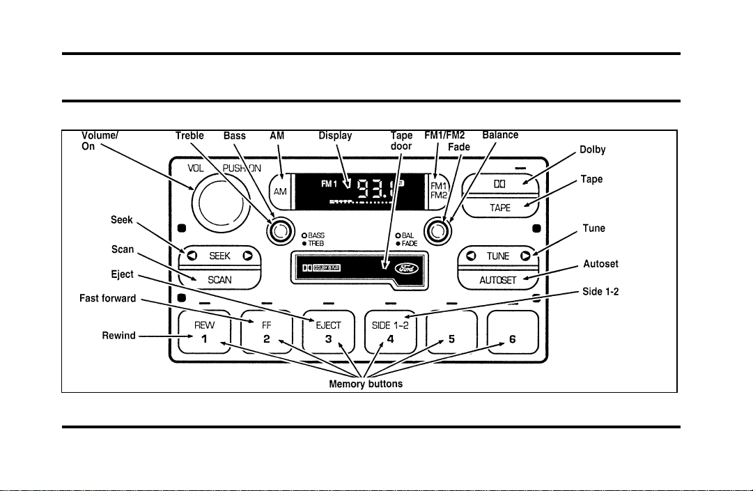
Luxury Audio System (Analog)
File:04fnasc.ex
Update:Mon Jun 17 14:15:17 1996
26
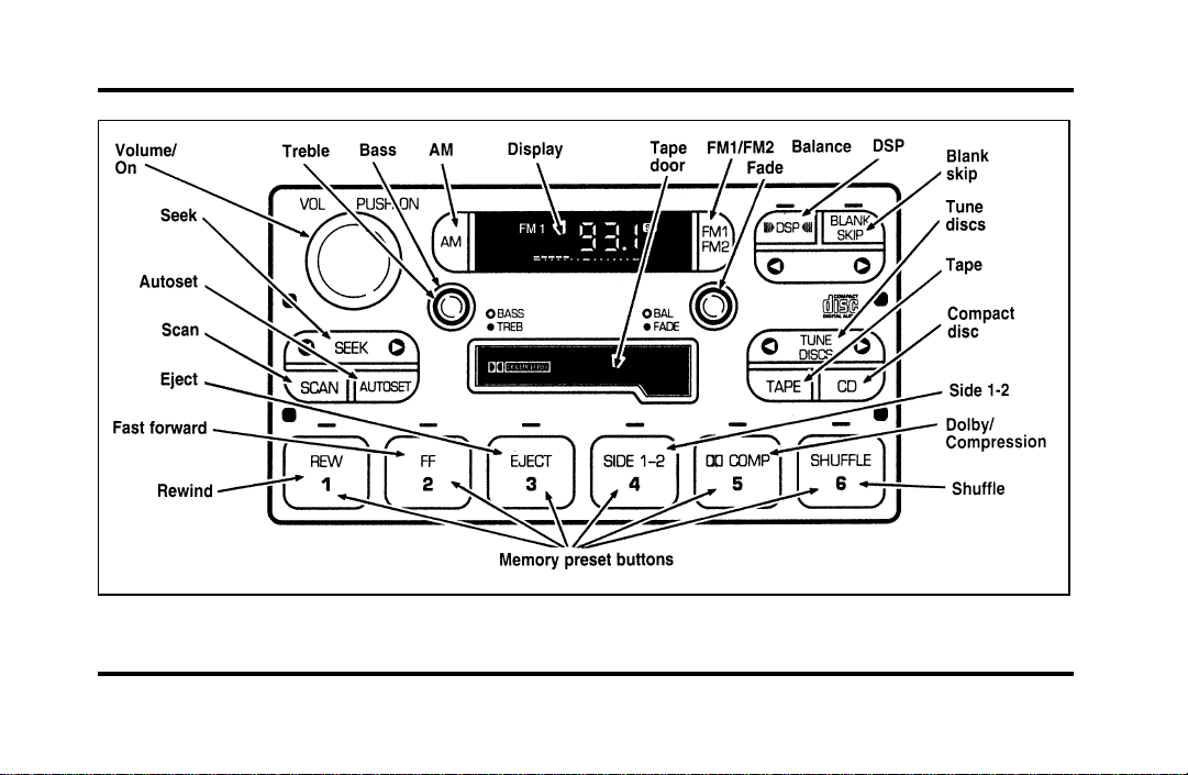
Luxury Audio System (Digital)
File:04fnasc.ex
Update:Mon Jun 17 14:15:17 1996

27
Luxury Audio System
Using the Controls on Your New Radio
How to turn the radio on and off
Press the “VOL/PUSH ON” knob to turn the radio
on. Press again to turn it off.
How to adjust the volume
Turn the “VOL/PUSH ON” knob clockwise to
increase the volume and counter-clockwise to
decrease the volume.
NOTE: If the volume is set above a certain level
when the ignition is turned off, the volume level
will reset to a “nominal” listening level when the
ignition switch is turned back on. However, if the
radio is turned off with the “VOL/PUSH ON” knob,
the volume will not reset and will stay at the same
level when the radio is turned back on.
Selecting the AM or FM frequency band
Push the “AM” or “FM1/FM2” button to select the
desired frequency band. Pushing the “FM1/FM2”
button more than once will alternate between FM1
and FM2. These functions are used with the
memory preset buttons described under How to
tune radio stations.
How to tune radio stations
There are four ways for you to tune in a particular
station. You can use the “TUNE”, “SEEK”, “SCAN”
or memory buttons.
❑
Using the “TUNE” function
You can change the frequency up or down one
increment at a time by pressing and releasing
either the left (
b
) or right (
a
) side of the
“TUNE” or “TUNE DISCS” button. To change
frequencies quickly, press and hold down either
the right or left side of the button.
File:04fnasc.ex
Update:Mon Jun 17 14:15:17 1996

28
Manual tuning adjusts your radio to any allowable
broadcast frequency, whether or not a station is
present on that frequency. (See All About Radio
Frequencies in this section.)
❑
Using the “SEEK” function
Press the right
a
side of the “SEEK” button to
select the next listenable station up the
frequency band. Press the left
b
side of the
button to select the next listenable station down
the frequency band. By holding the button
down, listenable stations can be passed over to
reach the desired station.
❑
Using the “SCAN” function
Pressing the “SCAN” button will begin the scan
mode up the frequency band, stopping on each
listenable station for approximately five seconds.
To stop the scan mode on the presently
sampled station, press the “SCAN” button again.
❑
Setting the station MEMORY PRESET buttons
Your radio is equipped with 6 station memory
buttons. These buttons can be used to select up
to 6 preset AM stations and 12 FM stations (6
in FM1 and 6 in FM2)
1. Select a band, then select a frequency.
2. Press one of the memory buttons and hold
until the sound returns and the lamp above the
memory button lights up. That memory button
is now set.
3. Follow the above steps for each memory preset
button.
NOTE: Custom memory presets can be recalled
using the keyless entry system. See Memory Profile
System in the Features chapter.
File:04fnasc.ex
Update:Mon Jun 17 14:15:17 1996

29
Using the Automatic Memory Store feature
(“AUTOSET”)
If the memory buttons have been set, either by
using the Auto Memory Load feature or if you have
set them manually, the system is prepared to let
you use a convenient feature called Automatic
Memory Store.
With Auto Memory Store, you can continually set
strong stations into your memory buttons without
losing your originally set stations. Your radio will
automatically set your memory buttons to the strong
local stations.
Activate Auto Memory Store by pushing the
“AUTOSET” button once. Your radio will set the
first six strong stations of the band you are in (AM,
FM1 or FM2) into the memory buttons. The display
will flash “AUTO” and display the autoset icon “A”
while the stations are being set in the memory
buttons.
NOTE: If there are less than six strong stations in
the frequency band, the remaining unfilled buttons
will store the last strong station detected on the
band. After all stations have been filled, the radio
will begin playing the station stored on memory
button 1.
To deactivate the Auto Memory Store mode and
return to the manually-set memory button stations,
simply push the “AUTOSET” button. Display will
show “AUTO” then “OFF”. The next time Auto
Memory Store is activated on that band, the radio
will store the next set of six strong stations.
File:04fnasc.ex
Update:Mon Jun 17 14:15:17 1996

30
Adjusting the tone balance of your radio
❑
Increasing or decreasing bass and treble
response
Push the “BASS/TREB” popout knob to gain
access to the bass and treble controls. Bass
control allows you to adjust the lower, bass
frequencies to your preference. The outer ring
of the “BASS/TREB” knob adjusts the bass (turn
clockwise to increase bass; counterclockwise to
decrease bass).
Treble control allows you to adjust the higher,
treble frequencies of your radio to your
preference. The inner ring of the “BASS/TREB”
knob adjusts the treble (turn clockwise to
increase treble; counterclockwise to decrease
treble).
❑
Adjusting speaker balance and speaker fader
Push the “BAL/FADE” popout knob to gain
access to the speaker balance and fader controls.
Balance control allows you to adjust the sound
distribution between the right and left speakers.
The outer ring of “BAL/FADE” knob adjusts the
speaker balance control. (Turn clockwise to shift
the sound to the right speakers, and turn
counterclockwise to shift the sound to the left
speakers.)
Fade control allows you to adjust the sound
distribution between the front and rear speakers.
The inner ring of the “BAL/FADE” knob adjusts
the speaker fader. (Turn clockwise to shift the
sound to the rear speakers, and turn
counterclockwise to shift the sound to the front
speakers.)
File:04fnasc.ex
Update:Mon Jun 17 14:15:17 1996

31
Using the Digital Signal Processing
(DSP) Feature
Push the “(
a
DSP
b
)” button to activate the
feature. The display will indicate which signal mode
is in effect. To change the signal mode press either
the left (
b
) or right (
a
) side of the selector
button (located under the “(
a
DSP
b
)” button).
The following signal modes may be selected:
1. “HALL” — Rectangular concert hall capacity of
about 2,000.
2. “CHURCH” — Church with a high vault.
3. “JAZZ” — Jazz club with clearly reflected
sounds.
4. “STADIUM” — Outdoor stadium with a
capacity of about 30,000.
5. “NEWS” — “Voice-only” type of sound with a
limited audio band.
To deactivate the DSP feature, press the
“(
a
DSP
b
)” button again.
Delayed Accessory Feature
(If Equipped)
If the ignition is turned off while the radio is on,
the radio will continue to play for up to ten
minutes or until a door is opened.
Speaker Locations
Your Ford JBL sound system is equipped with a
total of ten speakers: two speakers in each of the
four doors and two subwoofers located in the rear
package tray.
Your Antenna
Antennas for both AM and FM reception are hidden
in the back glass of your vehicle. There is an
internal antenna module that will switch between
AM and FM, when bands are changed, for
maximum reception performance.
File:04fnasc.ex
Update:Mon Jun 17 14:15:17 1996

32
NOTE: Do not attempt to adapt any other type of
antenna system to your audio system.
Using the Controls of Your Cassette
Tape Player
NOTE: Radio power must be on to use the cassette
tape player.
How to insert a tape
Your cassette tape player is equipped with power
loading. Once you insert a tape and push slightly
(with the open edge to the right), the loading
mechanism draws the tape the rest of the way in
and play will begin after a momentary tape
tightening process. Display indicates “TAPE” while
tape is playing.
If the player is in the tape mode but not in play,
pressing the “TAPE” button will activate play. If the
“TAPE” button is pressed with no tape inserted, the
display will flash “NO TAPE”.
How to locate a desired track on the tape
There are six ways to quickly locate a desired
selection on the tape. You can use the fast forward,
rewind, Blank Skip, “SEEK”, “SCAN” or “SIDE 1-2”
functions. Following are brief descriptions of each:
❑
Fast forwarding the tape
To fast forward the tape, press the “FF” button.
The radio will play while the tape is in fast
forward. The light above the “FF” button will
blink while in the fast forward mode. Press
“FF” again or press the “TAPE” button to stop
fast forwarding. At the end of the tape, the
direction automatically reverses and plays the
other side of the tape.
File:04fnasc.ex
Update:Mon Jun 17 14:15:17 1996

33
❑
Rewinding the tape
To rewind the tape, press the “REW” button.
The radio will automatically begin playing while
the tape is rewinding. The light above the
“REW” button will blink while in the rewind
mode. Press “REW” again or press the “TAPE”
button to stop rewinding.
❑
Using the “SEEK” function with your cassette
tape player
While in the tape mode, push the right
a
side
of the “SEEK” button to seek forward to the
next selection on the tape. Push the left
b
side to restart a currently playing tape selection.
❑
Using the “Blank Skip” function with your
cassette tape player
Press the “Blank Skip” button to activate the
blank skip mode. After approximately 20
seconds of blank program, the tape will seek
forward to the next program.
❑
Using the “SCAN” function with your cassette
tape player
Pushing the “SCAN” button will begin the
forward scan mode on the tape currently
playing, stopping on each tape selection for
approximately eight seconds.
To stop the scan mode on the presently sampled
tape selection, press the “SCAN” button or the
“TAPE” button.
❑
How to change the side of the tape being played
The alternate side of the tape can be selected
by pressing the “SIDE 1-2” button.
How to eject the tape
To stop the tape and eject the cassette, press the
“EJECT” button. The tape will eject only when in
the tape mode. The cassette cannot be ejected
when the radio is playing an “AM” or “FM”
station. The system will revert to radio mode when
the cassette is ejected.
File:04fnasc.ex
Update:Mon Jun 17 14:15:17 1996

34
How to store the tape
Press the “AM/FM” button to stop the tape player
and resume radio play.
Using the DolbyH B noise reduction
feature
NOTE: Noise reduction system manufactured under
license from Dolby Labs Licensing Corporation.
“Dolby” and double-D symbol are trademarks of
Dolby Laboratories Licensing Corporation.
Push the k button to activate. When activated,
the light above the k button will be illuminated.
Tape error messages
Your cassette tape player is equipped to diagnose
certain problems you may experience. Error codes
are as follows:
TD E1 — Radio tries to change sides of tape 3
times in a 10 second span. Push “EJECT” and try
another tape. If problem persists, refer problem to
qualified personnel for service.
TD E2 — Tape eject failure. Radio tries to eject
tape and it will not eject. Push “EJECT” to eject
tape. If the tape will not eject, refer problem to
qualified personnel for service.
TD E3 — Loading error. Push “EJECT” to eject
tape. Reload tape. If the same error code appears in
the display, try another tape.
Tips on Caring for the Cassette Player
and Tapes
In order to keep your cassette tape player
performing the way it was meant to, read and
follow these simple precautions:
❑
Using a Ford Cassette Cleaning Cartridge or
equivalent to clean the tape player head after
10-12 hours of play will help maintain the best
playback sound and proper tape operation.
❑
Only cassettes that are 90 minutes long or less
should be used. Tapes longer than 90 minutes
are thinner and subject to breakage or may jam
the tape player mechanism.
File:04fnasc.ex
Update:Mon Jun 17 14:15:17 1996

35
❑
Protect cassettes from exposure to direct
sunlight, high humidity and extreme heat or
cold. If they are exposed to extreme conditions,
allow them to reach a moderate temperature
before playing.
❑
If a tape is loose inside the cassette, tighten it
before playing by putting your finger or a pencil
into one of the holes and turning the hub until
the tape is tight.
❑
Loose labels on cassette tapes can become
lodged in the mechanism. Remove any loose
label material before inserting a cassette.
❑
Do not leave a tape in the cassette tape player
when not in use. High heat in the vehicle can
cause the cassette to warp.
Ford 6-CD Changer
Introduction
The Ford 6-CD Changer is mounted in your console
and holds 6 CDs, all controlled by using buttons on
your Luxury Audio System.
Be sure to read all of the information provided on
the following pages to get the most out of this
system.
File:04fnasc.ex
Update:Mon Jun 17 14:15:17 1996
36
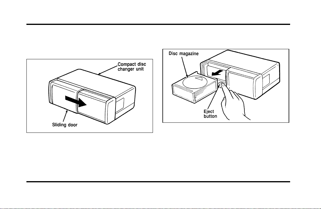
Loading Instructions
1. Open Compact Disc Changer unit by sliding
door to the right (Figure 1).
Figure 1
2. Push the i button to eject the disc “magazine”
(holds 6 discs) (Figure 2).
Figure 2
File:04fnasc.ex
Update:Mon Jun 17 14:15:17 1996
37
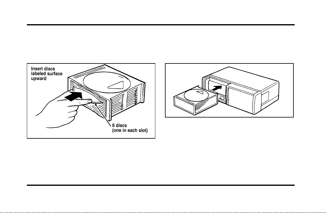
3. Load discs into the disc magazine slots
(numbered 1 through 6) one at a time with
labeled surfaces upward, starting with bottom
slot number 1 (Figure 3).
Figure 3
4. Insert loaded disc magazine into chamber unit
with the arrow on top of the disc magazine
pointing toward the changer (Figure 4). Make
sure magazine is fully inserted into changer.
Figure 4
NOTE: To remove one or more compact disc(s)
from the disc magazine, push the corresponding
lever(s) to the back. Disc(s) will partially come out
for easy removal.
5. Close unit by sliding changer panel door to the
left.
File:04fnasc.ex
Update:Mon Jun 17 14:15:17 1996

38
The Compact Disc Changer unit is now ready to
play using the controls of your Luxury Audio
System.
How to Operate the Ford 6-CD
Changer Using the Controls on the
Radio
If your vehicle is equipped with the Ford 6-CD
Changer System, you can operate it through the
controls of your Luxury Audio System.
Several of the controls on the radio operate in the
same manner in CD mode as they do in radio or
cassette mode: turning the power on, volume
control and adjusting the bass, treble, speaker
balance or fade.
How to begin CD Changer play
NOTE: Radio power must be on to operate the
Compact Disc Changer.
Push the “CD” button to begin CD play. The CD
Changer will automatically begin playing the first
track (selection) of the first disc loaded in the unit.
The display will indicate “CD-##” for disc number
then display “TR-##” for track number, then
“DD-TT” for disc number and track number.
How to change the disc being played
When in the CD mode, you can change discs by
pressing the right (
a
) side of the “TUNE DISCS”
button (to select the next disc) or the left (
b
) side
of the “TUNE DISCS” button (to select the previous
disc). Play will begin on the first track of the
selected disc.
When either side of the button is pressed and held,
the CD changer will continue fast-forwarding or
reversing through the discs in the disc magazine.
File:04fnasc.ex
Update:Mon Jun 17 14:15:17 1996

39
During these functions, the display will indicate the
disc number.
How to change the track being played
Press the right (
a
) side of the “SEEK” button to
seek forward to the next track of current disc. After
the last track has been completed, the CD player
automatically wraps back to the first track of the
current disc.
Press the left (
b
) side of the SEEK button to seek
in reverse to the previous track on the current disc.
If a selection has been playing for three seconds or
more and you press the left (
b
) side of the SEEK
button, the CD Changer will replay that selection
from the beginning.
Operating the CD Compression feature
The compression feature will bring soft and loud
passages closer together for a more consistent
listening level.
To turn the compression on, press the #5
“k/COMP” button. (While in the CD Changer
mode, the Dolby button controls the compression
function.) When the compression feature is
activated, the display will indicate “C”. Press again
to deactivate.
Operating the Shuffle feature
The shuffle feature on your CD player allows you to
listen to your disc selections in a different order.
When this feature is activated, your CD player will
randomly select and play tracks on the disc.
Press the #6 “SHUFFLE” button to turn on, press it
again to turn off. When on, the light above the
“SHUFFLE” button will illuminate.
File:04fnasc.ex
Update:Mon Jun 17 14:15:17 1996

40
Operating the “SCAN” function
Press the “SCAN” button to enter the scan mode.
The CD player will begin scanning the disc,
stopping on each listenable track for approximately
an eight second sampling. This continues until you
press the “SCAN” button a second time.
Operating the Shuffle and Scan features
simultaneously
Both the shuffle and scan features can be activated
simultaneously. In this mode, the player will
randomly pick a selection and play the first eight
seconds. This process is continued until either the
“SCAN” button or “SHUFFLE” button is pressed a
second time.
How to stop CD play
While in CD Changer mode, press the EJECT, AM
or FM1/FM2 button to stop CD play and resume
radio play. Also, loading a cassette into the cassette
deck will stop CD play and begin cassette play.
How to take care of and clean the CD
Changer and discs
To ensure the continued performance of your CD
Changer, carefully read the following precautions:
❑
Always handle a disc by the edge. Never touch
the playing surface.
❑
Before playing, inspect all discs for any
contamination. If needed, clean discs with an
approved disc cleaner, such as the DiscwasherH
Compact Disc Cleaner or the Allsop 3H
Compact Disc Cleaner, by wiping from the
center out to the edges. Do not use a circular
motion to clean.
❑
Do not clean discs with solvents such as
benzine, thinner, commercially available cleaners
or antistatic spray intended for analog records.
❑
Do not expose the discs to direct sunlight or
heat sources for an extended period of time.
File:04fnasc.ex
Update:Mon Jun 17 14:15:17 1996
41
❑
Donotinsertmorethanonediscintoeachdisc
slotofthediscmagazine.Doingsomaydamage
thediscs,discmagazineorthediscchanger.
❑
Donotinsertanythingotherthandiscsintothe
discmagazine.
WARNING
Thelaserbeamusedinthecompact
discplayerisharmfultotheeyes.Do
notattempttodisassemblethecase.
CDErrorMessages
Yoursystemisequippedtodiagnosecertain
problemsyoumayexperience.Theerrorcodesare:
—CDE1—Mechanismerror.
—CDE2—Focuserror.
—BADCD—Discunreadable.
—TOOHOT—Mechanismover167˚Farenheit,
allowtocoolbeforeplaying.
—NOCD—Emptyslotormagazine.
—NODJ—CDChangernotconnectedornot
communicating.
CommonOperatingConditionsofthe
CDPlayer
Thefollowinginformationisdesignedtohelpyou
recognizetypicalsituationsthatcouldbemistakenly
interpretedasmechanicalmalfunctionsofthedisc
player.
❑
Adiscisalreadyloaded.
❑
Thediscisinsertedwiththelabelsurface
downward.
❑
Thediscisdustyordefective.
❑
Theplayer’sinternaltemperatureisabove
167˚F(75˚C).Allowtheplayertocooloff
beforeoperating.
File:04fnasc.ex
Update:Mon Jun 17 14:15:17 1996

42
❑
Different manufacturers of compact discs may
produce discs with different dimensions or
tolerances, some of which may not be within
industry standards or in accordance with the
CD format. Because of this, a new disc that is
free of dust and scratches could be defective
and may not play on your Ford Compact Disc
Player.
If play does not begin after the CD button is
pushed:
❑
The radio is not on.
❑
The unit is in the stop mode.
❑
Moisture may have condensed on the lenses
within the unit. If this occurs, remove the disc
and wait approximately an hour until the
moisture evaporates.
If the sound skips:
❑
Badly scratched discs or extremely rough roads
will cause the sound to skip. Skipping will not
damage the disc player or scratch the discs.
Common Radio Reception
Conditions
Several conditions prevent FM reception from being
completely clear and noise-free, such as the
following:
Distance/Strength
The strength of the FM signal is directly related to
the distance the signal must travel. The listenable
range of an average FM signal is approximately 24
miles (40 km). Beyond this distance, the radio is
operating in a “fringe” area and the signal becomes
weaker. Also, “Signal Modulation” is used by some
stations to increase their “loudness” relative to other
stations. The difference in loudness can be a result
of signal modulation as well as signal strength.
File:04fnasc.ex
Update:Mon Jun 17 14:15:17 1996

43
Terrain
The terrain (hilly, mountainous, tall buildings) of the
area over which the signal travels may prevent the
FM signal from being noise-free.
Repeated pops and hisses which are heard during
an otherwise clear broadcast can occur near the
station because of the “line of sight” characteristic
of FM radio waves.
If there is a building or large structure between the
antenna and station, some of the signal “bends”
around the building, but certain spots receive almost
no signal. Moving out of the “shadow” of the
structure will allow the station to return to normal.
When the radio waves are reflected off objects or
structures, the reflected signal cancels the normal
signal, causing the antenna to pick up noise and
distortion. Cancellation effects are most prominent
in metropolitan areas, but also can become quite
severe in hilly terrain and depressed roadways.
To minimize these conditions, a stereo/mono blend
circuit has been incorporated into this system. This
feature automatically switches a weak stereo signal
to a clearer monaural signal, which improves the
quality of reception.
Several sources of static are normal conditions on
AM frequencies. These can be caused by power
lines, electric fences, traffic lights and
thunderstorms.
Another reception phenomenon is Strong Signal
Capture and Overload. This can occur when
listening to a weak station and when passing
another broadcast tower. The close station may
capture the more distant station, although the
displayed frequency does not change. While passing
the tower, the station may switch back and forth a
few times before returning to the original station.
File:04fnasc.ex
Update:Mon Jun 17 14:15:17 1996

44
When several broadcast towers are present
(common in metropolitan areas), several stations
may overload the receiver, resulting in considerable
station changing, mixing and distortion.
Automatic gain control circuitry for both AM and
FM bands has been incorporated into this system to
reduce strong signal capture and overload.
All About Radio Frequencies
The Federal Communications Commission (FCC)
and the Canadian Radio Telecommunications
Commission (CRTC) establish the frequencies that
AM and FM radio stations may use for their
broadcasts. The allowable frequencies are, AM: 530,
540...1600, 1610 kHz in 10 kHz steps; FM: 87.9,
88.1...107.7, 107.9 MHz in 0.2 MHz steps.
Not all frequencies will be assigned to a given area.
This radio will tune to each of these frequencies
using manual tune and no fine tuning is necessary
as radio stations may not use other frequencies.
Some FM radio stations advertise a “rounded-off”
frequency which is not the frequency they actually
broadcast on. For example, a radio station that is
assigned a frequency of 98.7 MHz may call itself
“Radio 99” even though 99.0 MHz is not an
allowable FM broadcast frequency.
Important Warranty and Service
Information
About Your Warranty
Your sound system is warranted for four years or
50,000 miles (whichever occurs first). Consult your
vehicle warranty booklet for further information.
Servicing Your Audio System
At Ford, we stand behind our audio systems with a
comprehensive service and repair program. If
anything should go wrong with your Ford audio
system, return to your dealer for service. There is a
nationwide network of qualified Ford authorized
repair centers to assist you.
File:04fnasc.ex
Update:Mon Jun 17 14:15:17 1996

45
Controls and Features
The Climate Control System
Electronic Automatic Temperature
Control System
The Electronic Automatic Temperature Control
(EATC) module is located at the center of the
instrument panel and operates only when the key is
in the ON position.
The EATC feature maintains the temperature you
select and automatically controls the airflow for
your comfort. It also allows you to override the
automatic operation with manual override buttons.
File:05fncfc.ex
Update:Fri Sep 6 14:53:57 1996
46
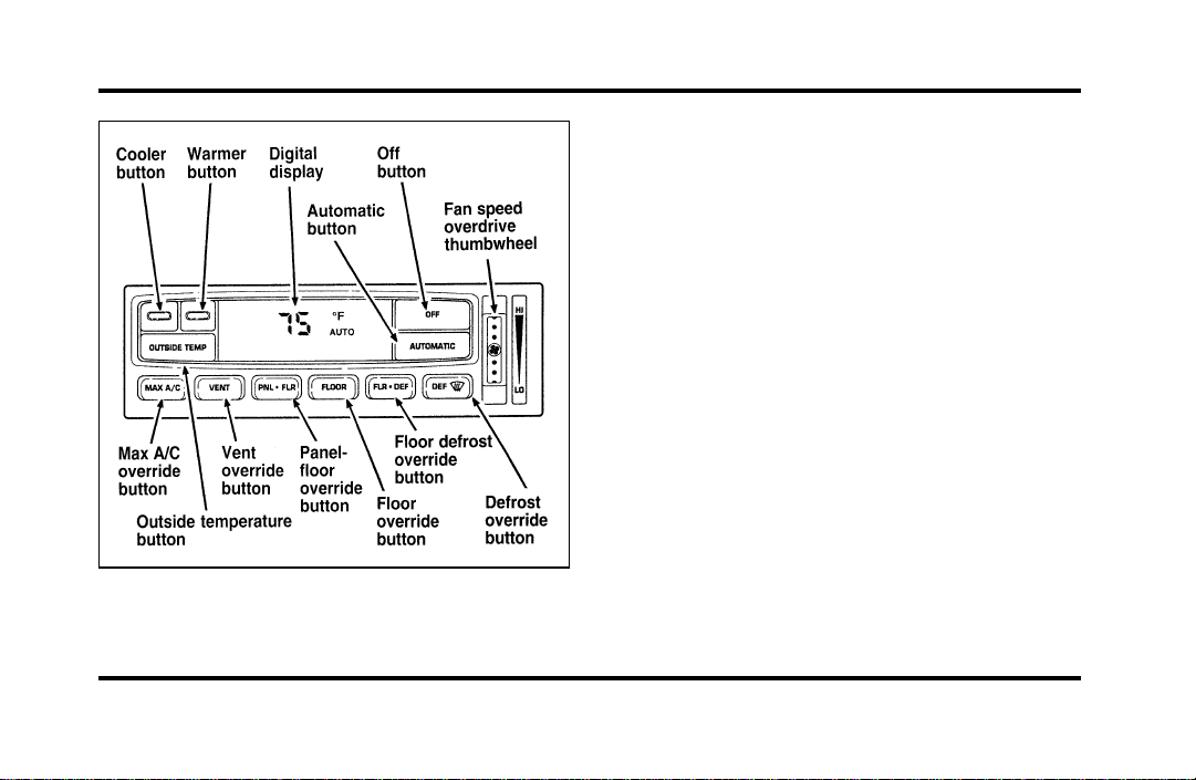
The automatic temperature control system
To turn your EATC on, push the AUTOMATIC
button or any of the six override buttons along the
bottom of the control.
To turn your EATC off, press the OFF button.
When the system is off, the display window will be
blank (dark) except when OUTSIDE TEMP has
been selected. Then, OUTSIDE TEMP and the
temperature will appear in the window.
If you select AUTOMATIC, the system will
automatically determine fan speed and airflow
location. If an override button is selected, your
selection determines airflow location only. Fan
speed remains automatic unless you override it by
rotating the vertical thumbwheel located at the
extreme right of the control panel.
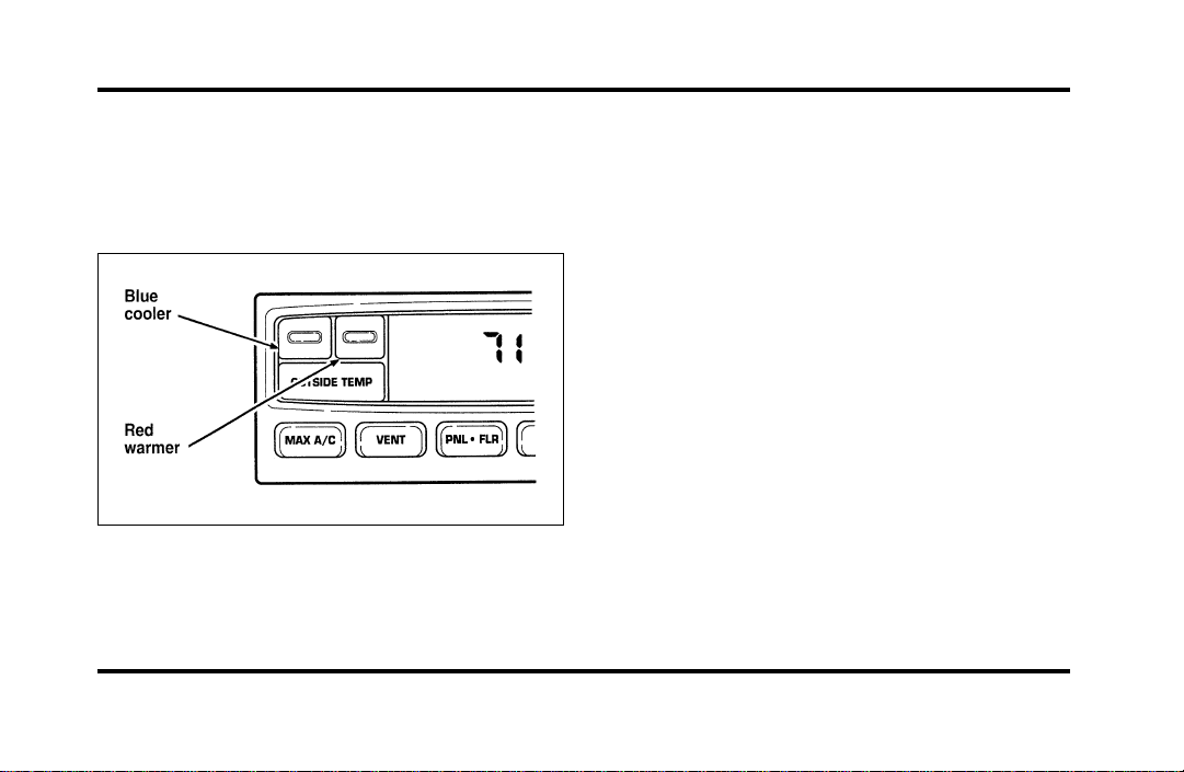
To change the temperature in the display window,
select any temperature between 65˚F (18˚C) and
85˚F (29˚C) using the BLUE (cooler) or RED
(warmer) buttons. The Electronic Automatic
Temperature Control will do the rest.
File:05fncfc.ex
Update:Fri Sep 6 14:53:57 1996
47
If you want continuous maximum cooling, push the
BLUE button until 60˚F (16˚C) is shown in the
display window. Your EATC will cool at maximum
and disregard the 60˚F (16˚C) setting until you
select a warmer temperature with the RED button.
If you want continuous maximum heating, push the
RED button until 90˚F (32˚C) is shown in the
display window. Your EATC will provide maximum
heat regardless of the 90˚F (32˚C) setting until you
select a cooler temperature with the BLUE button.
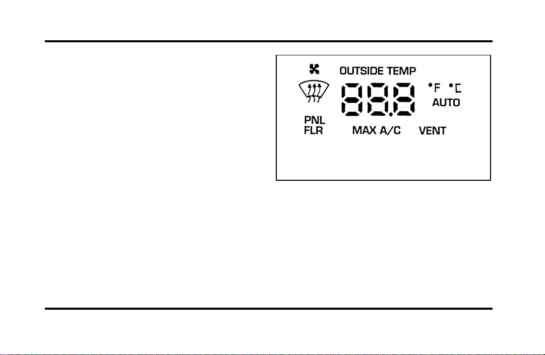
The display window tells you how the system is
operating. It will indicate the selected temperature
and the operating function you have chosen; AUTO
or one of the six manual overrides. It will also
indicate manual (thumbwheel) control of the fan
speed with the
H
symbol. The display window
with all possible displays and their positions are
shown here. Normally not all are shown at the
same time but are included here to familiarize you
with the names and symbols.
The display window
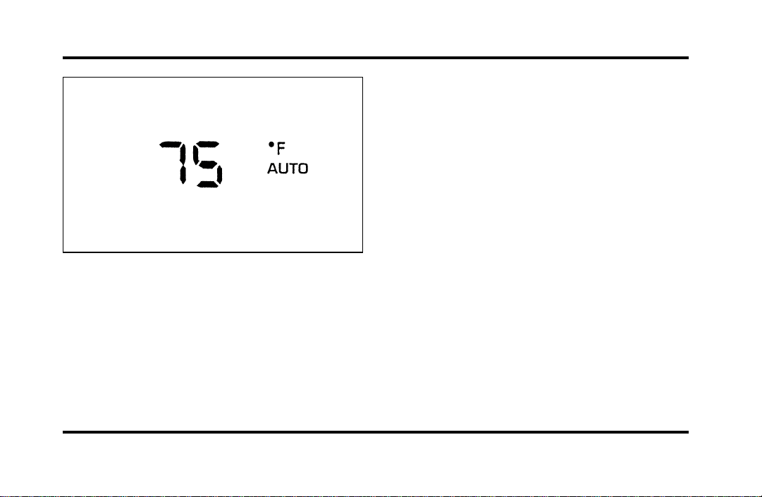
Automatic operation
Push the AUTOMATIC button and select the
desired temperature. The selected temperature and
AUTO will be shown in the display window. The
EATC will automatically heat or cool to achieve the
set temperature. Under normal conditions, your
EATC will need no additional attention.
File:05fncfc.ex
Update:Fri Sep 6 14:53:57 1996
48
The AUTO temperature display
When in AUTOMATIC and weather conditions
require heat, air will be sent to the floor. But, a
feature is included in your EATC to prevent
blowing cold air to the floor if the engine coolant is
not warm enough to allow heating. In 3-1/2
minutes or less, the fan speed will start to increase
and the airflow will change to the floor area.
If unusual conditions exist (i.e., window fogging,
etc.), the six manual override buttons allow you to
select special air discharge locations. A thumbwheel
allows you to adjust the fan speed to suit your
needs.
Temperature selection
The RED and BLUE buttons at the upper left of the
Control are for temperature selection. The RED
Button will increase the set temperature and the
BLUE Button will lower the set temperature.
Pressing a button and releasing it will change the
set temperature one degree. Holding either button
in will rapidly change the temperature setting in
one degree increments to either 65˚F (18˚C)
(BLUE) or 85˚F (29˚C) (RED). Then, the set
temperature will jump 5˚ and stop at either 60˚F
(16˚C) which is maximum cooling or 90˚F (32˚C)
which is maximum heating. When you select 60˚F
(16˚C) or 90˚F (32˚C), the fan will go to HI speed
for maximum air flow.
File:05fncfc.ex
Update:Fri Sep 6 14:53:57 1996
49
The normally selected temperature range is between
68˚F (20˚C) and 78˚F (26˚C). Changing the
temperature setting by several degrees outside this
range or overriding to 60˚F (16˚C) or 90˚F (32˚C)
will not speed up the heating or cooling process.
Temperature display
Press MAX A/C and DEF at the same time to
switch between Fahrenheit and Celsius. If the
battery is disconnected, the display will revert
to Fahrenheit.
Fan speed and thumbwheel
Your EATC automatically adjusts the fan speed to
the existing conditions. You must push
AUTOMATIC for automatic fan speed operation. To
control the fan speed yourself, use the thumbwheel
which will cancel the automatic fan speed control.
The thumbwheel is located at the extreme right
side of the EATC control panel. It is a vertical
control marked with a fan symbol. Rotate up for HI
and down for LO speeds.
File:05fncfc.ex
Update:Fri Sep 6 14:53:57 1996

50
When you move the thumbwheel, the fan speed
will go to manual control. The display window will
show the
H
symbol in the upper left corner along
with the selected temperature and operating
function.
You can override the fan speed at any time. If you
use the thumbwheel to override the fan speed, the
EATC will continue to control the temperature but
you control the fan speed. To return to auto fan
control, press the AUTOMATIC button. If you are
operating in one of the override functions (FLOOR,
MAX A/C, etc.), automatic fan control will
continue unless you rotate the fan thumbwheel. To
File:05fncfc.ex
Update:Fri Sep 6 14:53:57 1996

51
return to automatic fan control, press the
AUTOMATIC button. The EATC will return to
Automatic operation. If you want to return to any
override function, press the button for that function.
The fan speed will continue to be automatically
controlled.
Manual override buttons
Your EATC has six buttons which allow you to
make special selections. The buttons are located
along the bottom edge of the EATC control and
allow you to determine where the air will be
discharged. Pressing any override button changes
the air discharge location only. It does not affect
the ability of the system to control temperature or
the fan speed. Return to fully Automatic operation
by pushing the AUTOMATIC button.
MAX A/C button
The MAX A/C feature allows for faster cooling
because air is drawn from inside the vehicle. Using
inside air causes the fan to sound louder which is
normal for this selection. The Display window will
change to indicate 60˚F (16˚C) and MAX A/C. The
fan will run and the airflow will be from the
instrument panel registers. To exit and return to the
previous temperature, push AUTOMATIC or any of
the other five override buttons.
VENT button
Push this button to select outside air through the
instrument panel registers. The display window will
show the set temperature and VENT to the lower
right of the temperature. Your EATC will heat the
air if the temperature you have selected is warmer
than the outside air coming into the vehicle.
However, the air will NOT be cooled regardless of
the temperature setting.
File:05fncfc.ex
Update:Fri Sep 6 14:53:57 1996

52
PNL & FLR button
Push this button to get air from the floor and
instrument panel registers at the same time. The
display will show the set temperature and the
words PNL and FLR. Depending on the selected
temperature, the air will be automatically heated or
cooled.
FLOOR button
Airflow will be to the floor when the FLOOR
button is pressed. The display window will show
the set temperature and FLR to the left of the
temperature. The air cannot be cooled in the FLR
position, only heated. Fan speed will be automatic
unless manually controlled. If you override the fan
speed and wish to return to automatic fan control,
push AUTOMATIC. Then, again select FLOOR for
airflow to the floor.
FLR & DEF button
Push this button to get air to the floor and
windshield defrosters at the same time. The display
will show the set temperature, FLR and the Defrost
symbol. If the outside temperature is about 50˚F
(10˚C) and above, the air will be dehumidified to
remove moisture. This will help to prevent fogging
in humid weather.
DEF button
Press the Defrost Button to obtain maximum airflow
to the windshield. Adjust the temperature setting as
required for defrosting. The Display window will
show the temperature setting with the Defrost
symbol to the left of the temperature. When the
outside temperature is about 50˚F (10˚C) and
above, the air will be dehumidified to remove
moisture. This will help prevent fogging in humid
weather.
File:05fncfc.ex
Update:Fri Sep 6 14:53:57 1996
53
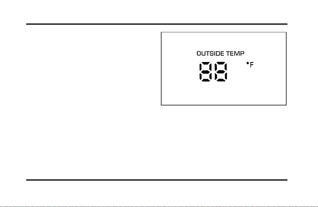
OUTSIDE TEMP button
By pressing this button the temperature of the air
outside of the vehicle will show in the display. The
outside temperature will continue to be displayed
until the OUTSIDE TEMP button is pressed again
to cancel. If the selected temperature setting is
changed while the outside temperature is displayed,
the new selected temperature will be displayed for
4 seconds after it is changed. Then, the outside
temperature will return to the window. If a manual
override is pressed or the thumbwheel is rotated
while the outside temperature is displayed, the
window will show the change for 4 seconds. Then,
the outside temperature will return along with the
changed override selection.
If the EATC is turned OFF while the outside
temperature is displayed, the temperature will
continue to be displayed. Press the OUTSIDE TEMP
button to clear the display window. When the
ignition key is turned OFF the display will be blank
(dark).
File:05fncfc.ex
Update:Fri Sep 6 14:53:57 1996

54
NOTE: The outside temperature reading is most
accurate when the vehicle is moving. Higher
readings may be obtained when the vehicle is not
moving. The readings that you get may not agree
with temperatures given on the radio due to
differences in vehicle and station locations.
Operating tips
The following tips will help you to get the most
satisfaction from your Electronic Automatic
Temperature Control system.
❑
In humid weather, select DEF V before
starting your engine. This will help to prevent
windshield fogging. After a few minutes of
operation, switch to AUTOMATIC or an
override selection of your choice.
❑
To prevent humidity buildup inside your
vehicle, always drive with the EATC System
turned on.
❑
Do not put objects under the front seats that
interfere with the flow of air to the back seat
area.
❑
Remove any snow, ice, or leaves from the air
intake area of your EATC System which could
block the air intake. The intake area is located
at the bottom of the windshield, under the
hood at the passenger side rear corner.
Service
If your EATC is not operating as described here,
take it to your dealer to have it checked. System
diagnostics are built in which will allow your dealer
to readily identify problems that might occur.
Passenger Compartment Air Filter
Your vehicle has an air filter that removes pollen
and road dust from outside air before it is directed
to the interior of the vehicle. For maintenance of
this filter, see the Maintenance and Care chapter.
File:05fncfc.ex
Update:Fri Sep 6 14:53:57 1996
55
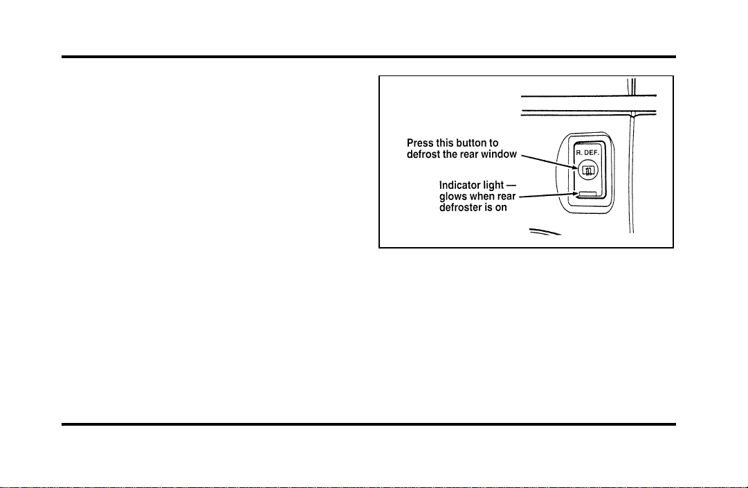
Rear Window Defroster and
Heated Sideview Mirrors
The rear window and heated outside mirrors
defroster switch activates the defroster for the rear
window to clear frost, fog, or thin ice from both
the inside and outside of the rear window and
activates the heated outside rearview mirrors.
The button for the rear window and heated outside
mirrors defroster is on the instrument panel to the
right of the steering column.
The button that controls the rear window
defroster and heated outside rearview mirrors
Before using the defroster, clear away any snow
that is on the rear window and outside rearview
mirrors. With the engine running, push the
defroster button.
File:05fncfc.ex
Update:Fri Sep 6 14:53:57 1996
56
Afterapproximately10minutes,thedefrosterwill
turnoff.Ifthewindowormirrorsarestillnotclear,
turnthedefrosteronagain.
Thedefrosterwillturnoffwhentheignitionkeyis
turnedtotheOFForSTARTposition.
Theheatingelementsarebondedtotheinsideof
therearwindow.Donotusesharpobjectsto
scrapetheinsideoftherearwindoworuse
abrasivecleanerstocleanit.Doingsocoulddamage
theheatingelements.
TheInteriorandExteriorLights
DaytimeRunningLightSystem
(Canadianvehiclesonly)
TheDaytimeRunningLight(DRL)systemturnsthe
highbeamheadlampson,withareducedlight
output,when:
❑
TheheadlampsystemisintheOFFposition,
and
❑
Thevehicleisrunning,and
❑
Thevehiclehasafullyreleasedparkingbrake.
Thehighbeamindicatorlightontheinstrument
clusterwillnotbeon.
NOTE:Ifyouhaveavehiclewithanautomatic
lightingsystem,theDRLsystemisactiveuntilthe
automaticsystemturnsontheheadlamps.
NOTE:Youmaynoticethatthelightsflickerwhen
thevehicleisturnedonoroff.Thisisanormal
condition.
WARNING
TheDaytimeRunningLight(DRL)
systemwillnotilluminatethetail
lampsandparkinglamps.Turnonyour
headlampsatdusk.Failuretodoso
mayresultinacollision.
File:05fncfc.ex
Update:Fri Sep 6 14:53:57 1996
57
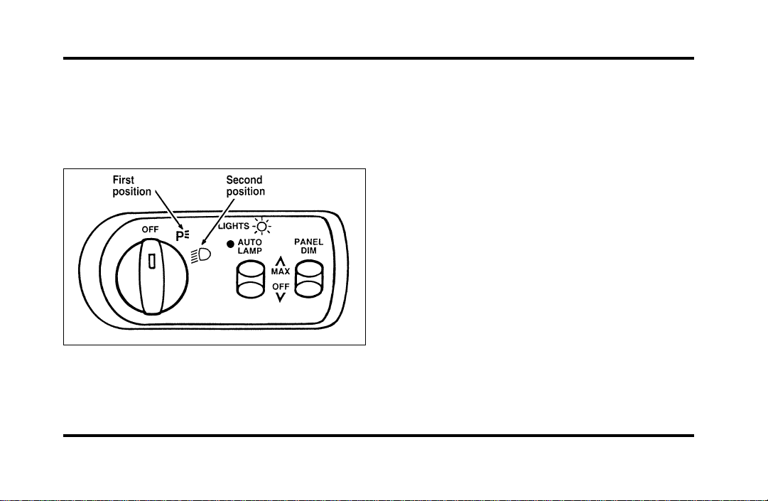
Turning On the Exterior Lights
To turn on the headlamps, parking lamps, side
markers, license plate lamps and tail lamps, use the
rotary control that is to the left of the steering
wheel.
The knob for the exterior lights
To turn on the parking lamps, tail lamps, side
markers, and license plate lamps, turn the knob
clockwise to the first position.
For more information about how the high beams
work, see the high beam section later in this
chapter.
Setting the Autolamp On/Off Delay
System
By using the autolamp, you can set the headlamps
to:
❑
turn on the lamps automatically at night
❑
turn off the lamps automatically during daylight
❑
keep the lamps on for up to three minutes after
you turn the key to OFF.
File:05fncfc.ex
Update:Fri Sep 6 14:53:57 1996
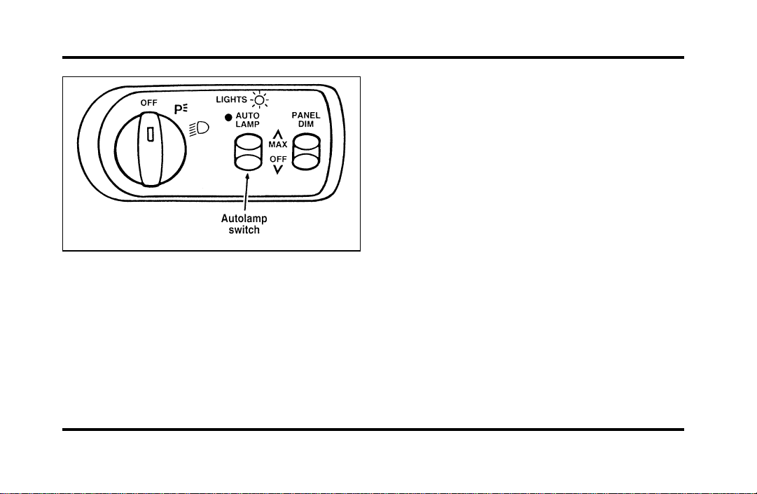
58
The autolamp switch on the left side of the
instrument panel
To use the autolamp:
1. Make sure the headlamp control is in the OFF
position. If the control for the headlamps is
ON, you cancel the autolamp.
If the autolamp is active, the headlamp system will
come on immediately after starting your vehicle. If
your vehicle is running before you activate the
autolamp, there may be a 15 second delay before
the headlights illuminate.
2. Turn the ignition key to ON or start your
vehicle.
3. Find the autolamp switch to the left of the
steering wheel on the instrument panel.
4. Push the autolamp switch up toward the MAX
position. As you press this switch, the autolamp
system’s status will be displayed in the message
center. The system can be turned OFF or can
be set to provide light for up to three (3)
minutes after you turn your vehicle off.
Do not put any articles on top of the photocell that
is located in the top left corner of the instrument
panel. This photocell controls the autolamp. If you
cover it, the photocell reacts as if it is nighttime,
and the lamps turn on.
File:05fncfc.ex
Update:Fri Sep 6 14:53:57 1996
59
To turn the autolamp off, push the switch down
until the message center display reaches OFF.
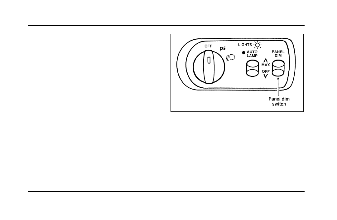
Turning On Interior Lights/Instrument
Panel Illumination
You can brighten or dim the lights in the
instrument panel and the compass display in the
inside rearview mirror (if equipped) with the
PANEL DIM switch located on the instrument
panel.
The switch that controls interior lamps and
instrument panel brightness
File:05fncfc.ex
Update:Fri Sep 6 14:53:57 1996
60
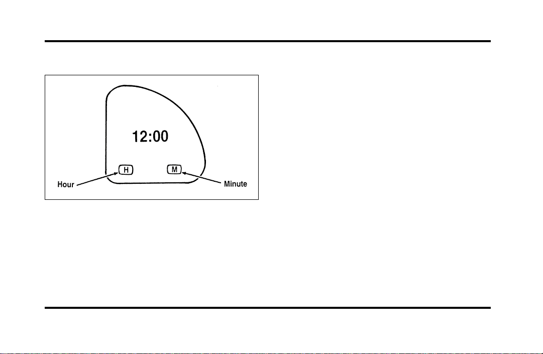
Clock
The digital clock
1. To set the hour, press and hold the hour
button. When the desired hour appears, release
the button.
2. To set the minutes, press and hold the minute
button. When the desired minute appears,
release the button.
Road Calibrated Suspension
Your Continental is equipped with a ride control
system that is designed to read disturbances in the
road surface every six inches at 60 mph
(100 km/h) to provide you with optimal driving
response.
Ride control allows you to chose both a ride feel
and steering effort that best fits your personal
driving style. These options may be selected by
using the RIDE/STEER Message Center button.
Pressing this button once will allow you to adjust
your RIDE CONTROL settings, between NORMAL,
PLUSH and FIRM. The settings are changed by
pressing the SELECT button while RIDE CONTROL
is displayed.
Pressing the RIDE/STEER button a second time will
allow you to adjust the STEERING EFFORT settings
between NORMAL, LOW, and HIGH. The settings
are changed by pressing the SELECT button while
STEERING EFFORT is displayed.
File:05fncfc.ex
Update:Fri Sep 6 14:53:57 1996
61
File:05fncfc.ex
Update:Fri Sep 6 14:53:57 1996
62
NOTE: The combination of FIRM RIDE CONTROL
and LOW STEERING EFFORT is undesirable and
cannot be selected.
Ignition
Understanding the Positions of the
Ignition
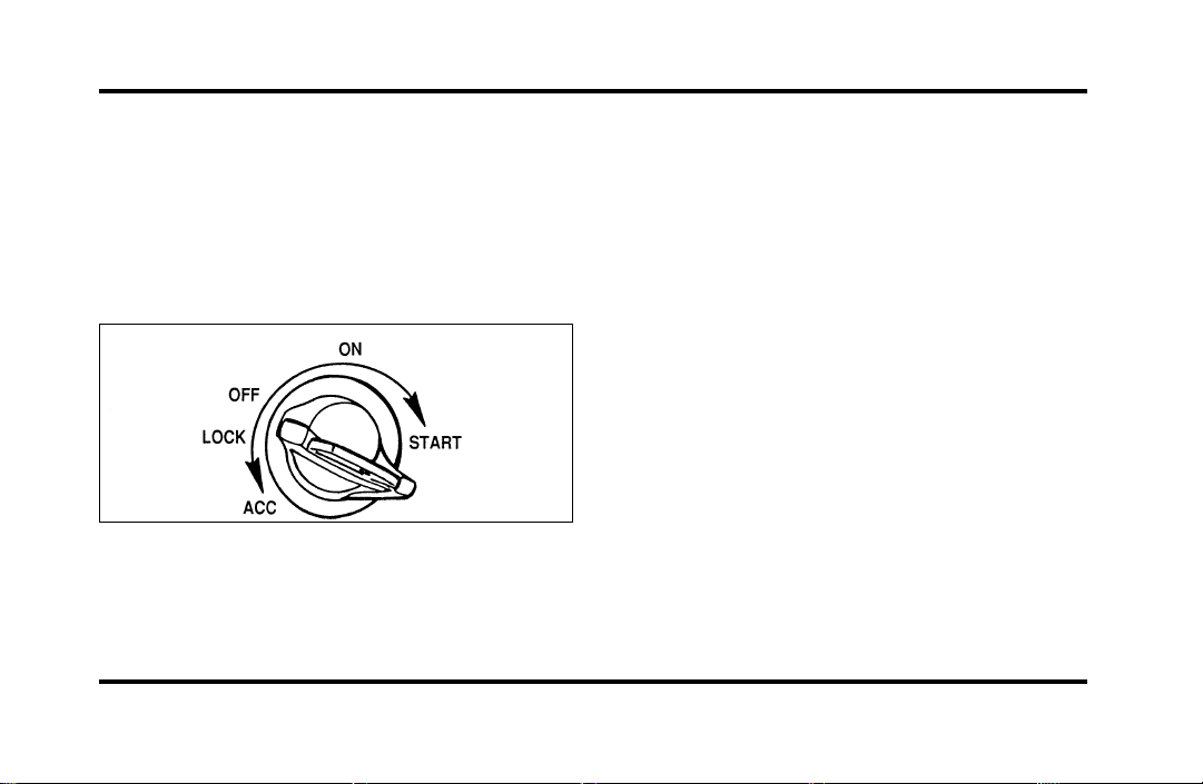
The positions of the key in the ignition
ACC allows some of your vehicle’s electrical
accessories such as the radio and the windshield
wipers to operate while the engine is not running.
NOTE: Your vehicle is also equipped with an
accessory timer. This allows some of your
accessories to remain on for up to 10 minutes after
the ignition is turned to the OFF position. The
accessory timer is cancelled if any door is opened,
the dimmer switch is used, or the ignition is turned
to the ON position.
The automatic transaxle gearshift must be in P
(Park) to move the key to the LOCK position.
LOCK locks the steering wheel. It also locks the
gearshift lever.
LOCK is the only position that allows you to
remove the key. The LOCK feature helps to protect
your vehicle from theft.
OFF allows you to shut off the engine and all
accessories without locking the steering wheel, or
the gearshift lever.
File:05fncfc.ex
Update:Fri Sep 6 14:53:57 1996
63
ONallowsyoutotestyourvehicle’swarninglights
(exceptthebrakesystemwarninglight)tomake
suretheyworkbeforeyoustarttheengine.Thekey
returnstotheONpositiononcetheengineis
startedandremainsinthispositionwhilethe
engineruns.
STARTcrankstheengine.Releasethekeyoncethe
enginestartssothatyoudonotdamagethestarter.
ThekeyshouldreturntoONwhenyoureleaseit.
TheSTARTpositionalsoallowsyoutotestthe
BrakeWarningLight.
RemovingtheKeyFromtheIgnition
1. PutthegearshiftinP(Park).
2. Settheparkingbrakefully.
3. TurntheignitionkeytoLOCK.
4. Removethekey.
IfthekeyisstuckintheLOCKposition,movethe
steeringwheelleftorrightuntilthekeyturns
freely.
Ifthedriver’sdoorisopenwhilethekeyisstillin
theignition,awarningchimesounds.
WARNING
Alwayssettheparkingbrakefullyand
makesurethegearshiftislatchedinP
(Park).Turnofftheignitionwhenever
youleaveyourvehicle.
WARNING
Donotleavechildren,unreliableadults,
orpetsunattendedinyourvehicle.
File:05fncfc.ex
Update:Fri Sep 6 14:53:57 1996

64
The Turn Signal Lever
You can use the turn signal lever on the left side of
the steering column to:
❑
operate the turn signals and cornering lamps
❑
turn the high beams on/off
❑
flash the lights
❑
turn the windshield wipers and washer on/off
The turn signal lever
File:05fncfc.ex
Update:Fri Sep 6 14:53:57 1996

65
Turn Signals
Move the lever up to signal a right turn. Move it
down to signal a left turn. The corresponding
indicator light in the instrument cluster will flash.
If the turn signal stays on after you turn, move the
lever back to the center (off) position. A warning
chime will sound after approximately one-half mile
(one kilometer) of driving if you do not return the
lever to off.
For lane changes, move the lever far enough to
signal but not to latch. The lever will return to the
off position when you release it.
NOTE: The flash rate of the turn signal will speed
up considerably if the Lighting Control Module
detects a left or right turn lamp bulb (front or rear)
is burned out.
High Beams
To turn on the high beams, turn the headlamp
control switch to the headlamp ON position (or
activate the autolamp feature) and push the turn
signal lever away from you until it latches. When
the high beams are ON, the high beam indicator
light on the instrument cluster comes on.
To turn off the high beams, pull the lever toward
you until it latches. The high beam indicator light
turns off.
Flashing the Lights
To flash the headlamps, pull the lever toward you
for a moment and then release it. The headlamps
will flash whether the headlamp knob is in the on
or off position.
File:05fncfc.ex
Update:Fri Sep 6 14:53:57 1996
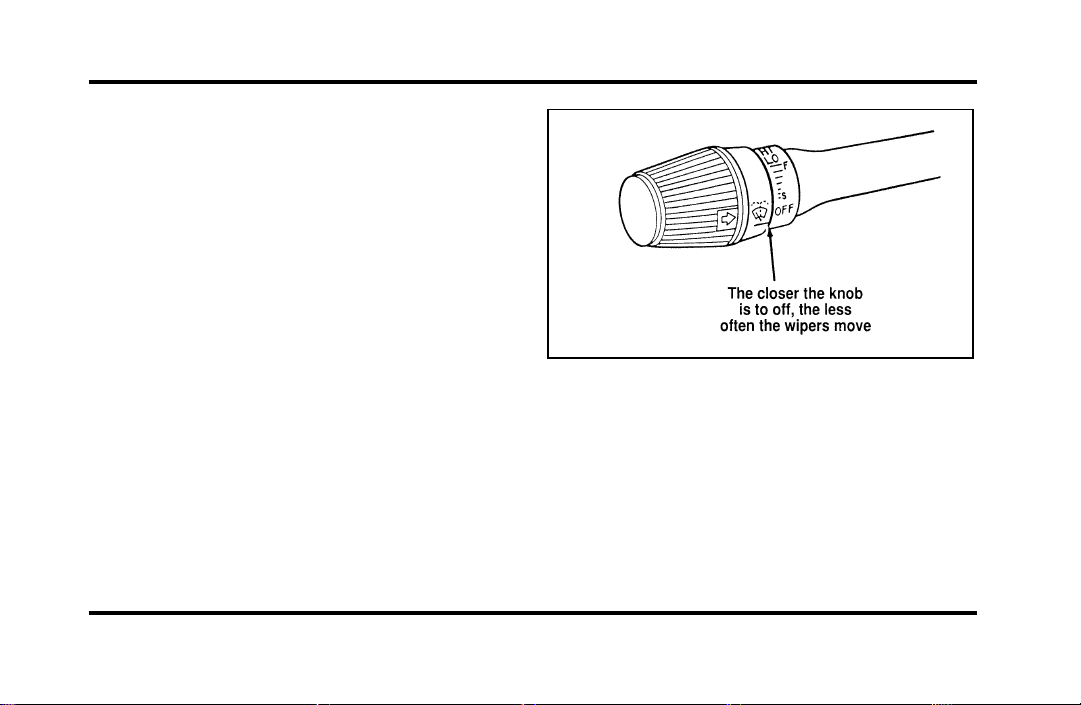
66
Windshield Wipers and Washer
To turn on the windshield wipers, the ignition key
must be turned to the ON or ACC position.
Rotate the knob towards “S” to activate the wipers.
The first seven detents are interval wipe positions,
the eighth detent is the LO position and the ninth
detent is the HI position.
To turn the wipers off, turn the knob to the OFF
position.
Variable Interval Wipers
In addition to two speed wipers, your vehicle has
wipers that you can set to operate at varying
intervals. For example, you can set the interval so
they wipe less often when it drizzles or more often
in heavier rain.
The windshield wiper on the turn signal lever
To set the interval wipers, turn the knob at the end
of the turn signal lever between “S” (slow) and “F”
(fast) until the desired interval between wipes is
achieved.
File:05fncfc.ex
Update:Fri Sep 6 14:53:57 1996
67
WindshieldWasher
Tocleanthewindshield,pushintheendofthe
wiperknob.Foraconstantspray,keeptheknob
pushedin.Afteryoureleasetheknob,thewipers
operatefortwotothreecyclesbeforeturningoff(if
thewiperswereOFF)orreturningtoHI,LO,or
theintervalsettingselected.
Ifthewasherdoesnotwork,checkthewasher
fluidlevelandfillitifitislow.Seethe
MaintenanceandCarechapter.Ifthereisenough
fluid,consultyournearestFordorLincoln-Mercury
dealer.
Donottrytocleanthewindshieldwhenthe
washerfluidcontainerisemptyoractivatethe
washersatanytimeformorethan15seconds
continuously.Thiscoulddamagethewasherpump
system.
WARNING
Alwayswarmupthewindshieldwith
thedefrosterbeforeyouusethewasher
fluid.Infreezingweather,thewasher
solutionmayfreezeonthewindshield
andobscureyourvision.
Forinformationaboutrefillingthewasherfluidor
replacingyourwindshieldwiperblades,see
WindshieldwasherfluidandWipersintheIndex.
File:05fncfc.ex
Update:Fri Sep 6 14:53:57 1996
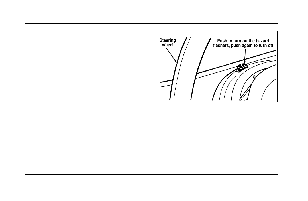
68
Hazard Flasher
The hazard flasher serves as a warning to other
drivers to be careful when approaching or passing
your vehicle.
The control switch for the hazard flashers
File:05fncfc.ex
Update:Fri Sep 6 14:53:57 1996
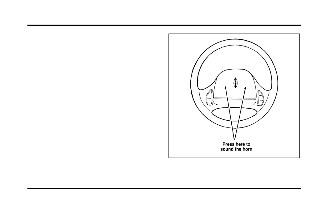
69
Horn
To sound the horn, push the center pad area of the
steering wheel.
The horn on the steering wheel.
File:05fncfc.ex
Update:Fri Sep 6 14:53:57 1996

70
TiltSteering
WARNING
Neveradjustthesteeringwheelwhen
thevehicleismoving.
Thelevertotiltthesteeringwheel
File:05fncfc.ex
Update:Fri Sep 6 14:53:57 1996

71
To change the position of the steering wheel, pull
the release lever on the column toward you. Tip
the steering wheel to the desired position. Release
the lever to lock the steering wheel in place.
Speed Control
The speed of the vehicle cannot be automatically
controlled until the vehicle speed is at or above 30
mph (48 km/h).
Use of radio transmitting equipment that is not
Federal Communications Commission (FCC) or in
Canada the Canadian Radio and
Telecommunications Commission (CRTC) approved
may cause the speed control to malfunction.
Therefore, use only properly installed FCC (CRTC in
Canada) approved radio transmitting equipment in
your vehicle.
NOTE: Since your vehicle has an Automatic
Overdrive Transaxle, you may want to drive in D
(Drive) when driving in hilly terrain, at higher
altitudes, or when pulling a trailer. This will
improve speed control performance.
NOTE: Do not shift to N (Neutral) when using the
speed control. This will cause the engine to
overspeed.
File:05fncfc.ex
Update:Fri Sep 6 14:53:57 1996
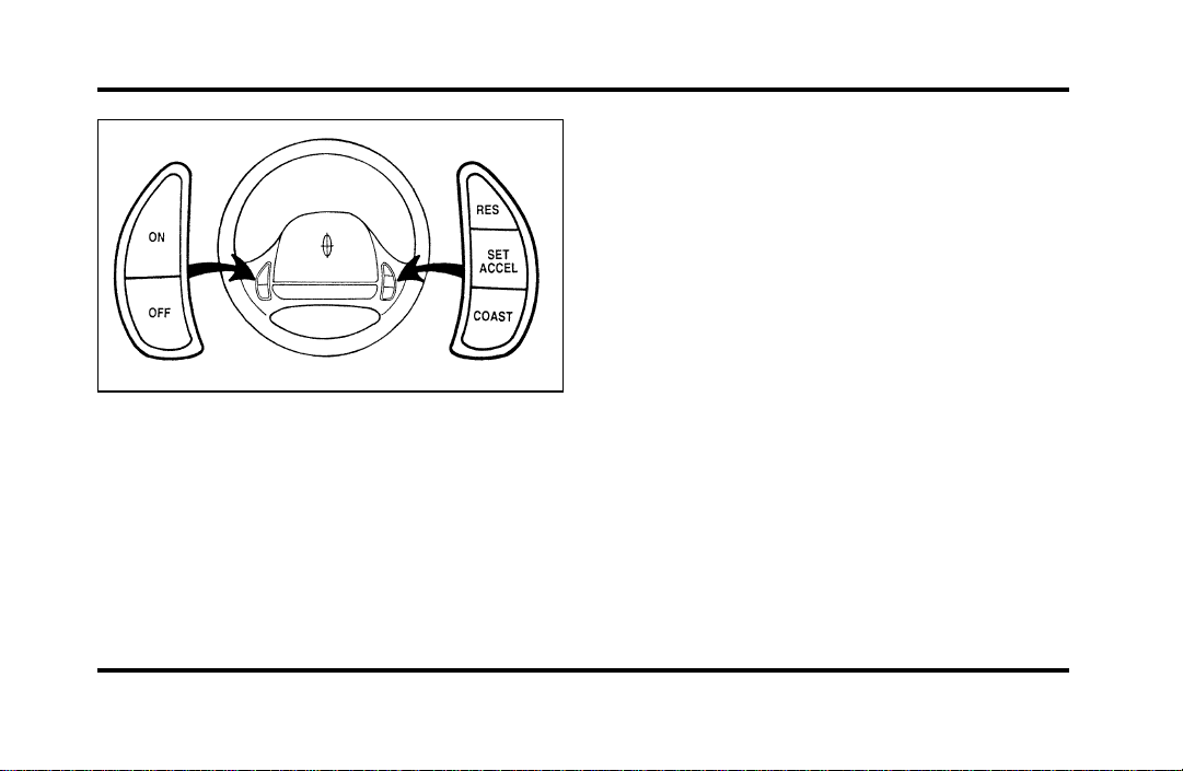
72
The speed control switches on the steering
wheel
To Turn Speed Control Off
❑
Press OFF, OR
❑
Turn off the vehicle ignition.
Once speed control is switched off, the previously
programmed set speed will be erased.
To Turn Speed Control On
❑
Press ON
To Set a Speed
Press SET ACCEL. For speed control to operate, the
speed control must be ON and the vehicle speed
must be greater than 30 mph (48 km/h).
If you drive up or down a steep hill, your vehicle
speed may vary momentarily slower or faster than
the set speed. This is normal.
Speed control cannot reduce the vehicle speed if it
increases above the set speed on a downhill. If your
vehicle speed is faster than the set speed while
driving downhill in j (Overdrive), you may want
to shift to the next lower gear to reduce your
vehicle’s speed.
If your vehicle slows down more than 10 mph
(16 km/h) below your set speed on an uphill, your
speed control will disengage. This is normal.
Pressing RES (Resume) will re-engage it.
File:05fncfc.ex
Update:Fri Sep 6 14:53:57 1996

73
WARNING
Tokeepyourvehicleundercontrol,do
notusespeedcontrolinheavytrafficor
onroadsthatarewinding,slippery,or
unpaved.
ToSetaHigherSetSpeed
❑
PressandholdSETACCEL.Releasetheswitch
whenthedesiredvehiclespeedisreached.OR
❑
PressandreleaseSETACCEL.Eachpresswill
increasethesetspeedby1mph(1.6km/h).
OR
❑
Acceleratewithyouracceleratorpedal,then
pressSETACCEL.
Youmayacceleratewiththeacceleratorpedalat
anytimeduringspeedcontrolusage.Releasingthe
acceleratorpedalwillreturnyourvehiclespeedto
thepreviouslyprogrammedsetspeed.
ToSetaLowerSetSpeed
❑
PressandholdCOAST.Releasetheswitch
whenthedesiredvehiclespeedisreached.OR
❑
PressandreleaseCOAST.Eachpresswill
decreasethesetspeedby1mph(1.6km/h).
OR
❑
Depressthebrakepedal.Whenthedesired
vehiclespeedisreached,pressSETACCEL.
ToDisengageSpeedControl
❑
Depressthebrakepedal.
Disengagingthespeedcontrolwillnoterasethe
previouslyprogrammedsetspeed.
ToReturntoaSetSpeed
❑
PressRES(RESUME).ForRES(RESUME)to
operate,thevehiclespeedmustbefasterthan
30mph(48km/h).
File:05fncfc.ex
Update:Fri Sep 6 14:53:57 1996
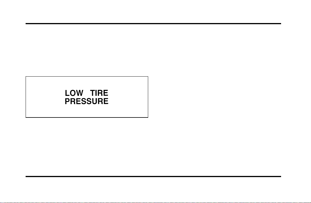
74
Overhead Console Warnings
If your Continental is equipped with the Pressure
Alert System, a warning will appear in the overhead
console when the pressure in one of your vehicle’s
tires drops below acceptable levels or if the system
has malfunctioned.
See SecuriTires in the Maintenance and Care
chapter for more information.
Lincoln RESCU System
(If equipped)
Lincoln RESCU runs a self-test when you start your
vehicle. During this test, the Lincoln RESCU
warning light, located in the overhead console, will
briefly illuminate. If a problem is detected during
the self-check, the light will remain lit and the
message “RESCU FAILURE” will be displayed on
the vehicle’s message center for several seconds.
If the warning light fails to briefly illuminate when
you start your vehicle or if it remains lit, have your
Lincoln RESCU System checked by an authorized
Lincoln/Mercury dealer as soon as possible. Your
system may be inoperative.
File:05fncfc.ex
Update:Fri Sep 6 14:53:57 1996
75
WARNING
Itisimportantthatyouunderstandthe
capabilityofyourLincolnRESCU
Systempriortoinitiatinganactivation.
SeeImportantThingstoKnowAbout
YourLincolnRESCUSystemlaterinthis
chapterfordetails.
QuickSummary
❑
Toutilizeyourvehicle’sRESCUsystem,YOUR
CELLULARPHONEMUSTBEACTIVATED.
❑
Roadsideoremergencyassistancecanbe
requestedwheneveryourkeyisinthe
RUN/STARTpositionandfortwominutesafter
thevehicleisturnedoff.
❑
Anassistancerequestisinitiatedbypressing
eitherthetowtruckorambulancebutton
locatedintheoverheadconsole.
❑
Whenabuttonispressed,awarninglamp
locatedintheoverheadconsolebeginstoflash
andstatusmessagesaredisplayedonthe
vehicle’smessagecenter(messagesareonly
displayedwhenyourkeyisintheRUN/START
position).
❑
Thevehicle’scellularphoneautomaticallyplaces
acalltoa24houremergencyresponsecenter.
❑
Whencontactismade,thevehiclesendsan
electronicdatamessagetotheresponsecenter’s
computer.Thisdatamessageincludeslatitude
andlongitudecoordinatesobtainedfromthe
vehicle’spositioningsystem.
❑
Oncethedatatransmissioniscomplete,thecall
isforwardedtoaresponsecenteroperatorwho
confirmsyourlocationusingacomputerized
map.
File:05fncfc.ex
Update:Fri Sep 6 14:53:57 1996

76
❑
The vehicle’s cellular handset is locked-out, the
phone is automatically placed in “hand free”
mode and voice communication is established
with the operator through the “hands free”
microphone.
❑
Typically, voice communication with an operator
is established within one minute after an
assistance button is pressed.
❑
The operator verbally obtains details of your
situation and, if necessary, ties your vehicle into
a three-way phone call with the United States
Auto Club or local 911 or other emergency
services to dispatch the appropriate assistance to
your location.
❑
Once the situation has been appropriately
handled, the operator will terminate the call,
the system warning light will stop flashing and
the system will be reset. In most situations,
ONLY the response center can terminate an
assistance request.
General Description
Lincoln’s Remote Emergency Satellite Cellular Unit
(RESCU) is designed to expedite roadside or
emergency assistance to distressed motorists who
are uncertain of their location and/or are uncertain
of who to contact for assistance.
The Lincoln RESCU System utilizes Global
Positioning System (GPS) technology and the
nation’s cellular phone network to track vehicle
location and, at the touch of a button, put you in
voice contact with the Lincoln Security Response
Center.
Two buttons in the overhead console will activate
the system. A tow truck icon for roadside assistance
and an ambulance icon for emergency assistance
identify the buttons.
File:05fncfc.ex
Update:Fri Sep 6 14:53:57 1996
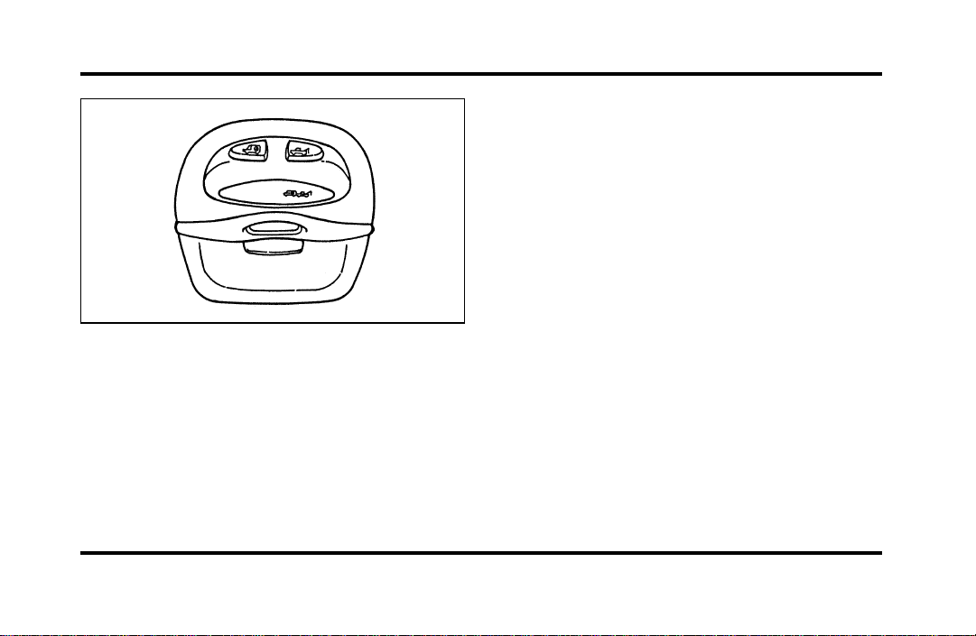
77
The Overhead Console
When you select a button, the vehicle’s cellular
phone will automatically place a data call to the
response center’s central computer. Once contact is
made, an electronic data message will be
transmitted. This data message will include:
❑
Type of alarm (roadside or emergency)
❑
Vehicle Identification Number (VIN)
❑
Latitude and longitude coordinates
❑
Last recorded speed and direction of the vehicle
❑
Time tag identifying when last position was
taken
❑
Call-back phone number
After the transmission is complete, the call is
forwarded to an operator who will verify the details
of the request and confirm the vehicle’s location
using computerized map.
Tow Truck Button (Roadside
Assistance)
The tow truck button should be selected if roadside
assistance is required. The feature should be used:
❑
when your vehicle runs out of gas
❑
when your vehicle needs a tow
❑
to acquire assistance in any non-emergency
situation
File:05fncfc.ex
Update:Fri Sep 6 14:53:57 1996
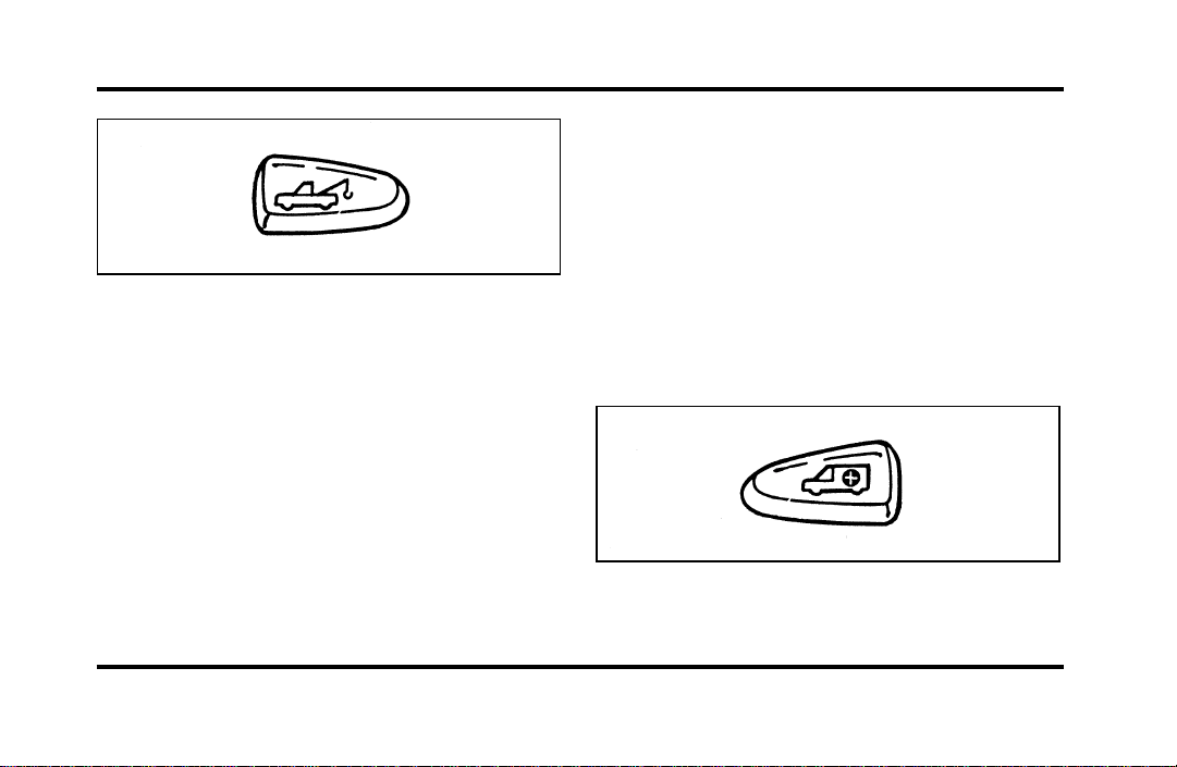
78
The Roadside Assistance button
When this button is pressed, the Lincoln Security
Response Center relays details of your situation and
your location to the United States Auto Club
(USAC) via a three-way phone call. The response
center/USAC will:
❑
dispatch the appropriate service vehicle to your
location.
❑
provide the service vehicle’s estimated time of
arrival.
❑
call back approximately three minutes after the
service vehicle’s estimated time of arrival to
confirm that assistance has arrived.
Ambulance Button (Emergency
Assistance)
The ambulance button should be selected if
emergency assistance is required. This feature
should be used:
❑
if you have been involved in an accident
❑
to report a crime or fire
❑
when medical attention is required
❑
to receive assistance in any emergency situation
The Emergency Assistance button
File:05fncfc.ex
Update:Fri Sep 6 14:53:57 1996

79
When this button is pressed, the Lincoln Security
Response Center relays details of your situation and
your location to local 911 or other emergency
services via a three-way phone call. The response
center/emergency services will:
❑
dispatch the appropriate emergency help to your
location
❑
when appropriate, stay in direct phone contact
with you until emergency help arrives
❑
notify pre-designated family contacts or friends
of the emergency situation, if requested, or if no
response is received from the vehicle.
NOTE: If you are certain of your location, a direct
phone call to 911 or other emergency services may
provide a faster response.
Activation and Deactivation
When either of the two Lincoln RESCU buttons is
pressed, a warning light, located in the overhead
console, will begin to flash and status messages will
be displayed on the vehicle’s message center,
confirming an assistance request has been made.
The warning light will continue to flash throughout
the activation.
The RESCU Warning light
The system can be activated whenever your ignition
key is in the RUN/START position and for two
minutes after your vehicle is turned off. Once a
RESCU button has been pressed, DO NOT
ATTEMPT TO CRANK THE ENGINE as this may
cancel the activation. In most situations, the
assistance request can ONLY be terminated and the
system reset when a special tone is sent to the
File:05fncfc.ex
Update:Fri Sep 6 14:53:57 1996

80
vehicle by the Lincoln Security Response Center.
(See Automatic Redial later in this chapter for
exceptions.) Operation will continue even if the
vehicle is turned off during an activation (although
visual feedback via the Message Center will not be
available in this situation).
Cellular Phone Interface
During an activation, Lincoln RESCU takes control
of the vehicle’s cellular phone. If the phone is in
use, THE CALL WILL BE TERMINATED and the
Lincoln Security Response Center will automatically
be dialed. The cellular handset becomes inoperative
and all voice communication with the operator is
accomplished via the cellular phone’s “hands-free”
microphone.
NOTE: When an activation is terminated, your
phone is left unlocked, in the “ON” state and may
not return to its previous call restriction or system
selection setting. It can be reprogrammed to your
previous setting as desired.
Message Center Interface
During an activation, Lincoln RESCU communicates
with the vehicle’s Message Center. Status messages
describing the sequence of steps being executed are
displayed, allowing you to visually follow the
activation process. The following messages are
typical of those displayed during an assistance
request. They are shown in the order in which they
would appear:
❑
ROADSIDE REQUEST or EMERGNCY
REQUEST
❑
CALL IN PROGRESS
❑
RINGING RESPONSE CENTER
❑
SENDING LOCATION DATA
❑
DATA RECEIVED
❑
WAITING FOR OPERATOR
File:05fncfc.ex
Update:Fri Sep 6 14:53:57 1996

81
Once an assistance request is made, it will typically
take less than one minute until contact is made
with an operator. During voice communication the
following messages will alternately toggle on the
display:
❑
CID XXXXXXXXXX
❑
LAT XXXXXXXXXX
❑
LON XXXXXXXXXX
❑
HDG XX
These messages respectively are the customer
identification number, vehicle latitude, vehicle
longitude and heading. Under special circumstances,
the operator may ask you to read the information
being displayed on the Message Center.
If vehicle messages are being displayed on the
Message Center (low washer fluid, low oil, door
ajar, etc.), they must be cleared in order to view
the LINCOLN RESCU messages. To clear the
vehicle messages, press the Message Center RESET
button, which is located to the right of the display.
Continue pressing the button until all vehicle
messages are cleared.
Automatic Redial
As described previously, when an assistance request
is made, the vehicle’s cellular phone automatically
dials the Lincoln Security Response Center’s central
computer and attempts to send an electronic data
message. Occasionally, it can be difficult for the
computer to recognize the message if the cellular
connection is weak or noisy. If the transmission of
the message is unsuccessful, the data call will be
terminated and the message “REDIAL IN
PROGRESS” will be displayed on the Message
Center. A second call will automatically be placed
which bypasses the response center’s computer and
is forwarded directly to an operator.
File:05fncfc.ex
Update:Fri Sep 6 14:53:57 1996

82
Similarly, if the cellular call is disconnected by the
network prior to receipt of the termination tone,
another call to the response center will also
automatically be dialed. The message “REDIAL IN
PROGRESS” will be displayed on the Message
Center and voice communication with an operator
will be restored.
NOTE: During redial calls, full control of the
cellular phone is returned to you. Pressing either
the “PWR” or “END” button on the cellular
handset will terminate the assistance request and
reset the system.
Location Data Retransmit Capability
During an activation, the Lincoln Security Response
Center operator has the capability to initiate a
retransmission of the electronic data message. This
may be necessary to ensure a more precise
determination of vehicle location or to track a
vehicle that is moving. To accomplish the
retransmit, a special tone is sent to the vehicle by
the response center. In this situation you will
temporarily lose voice contact with the operator and
the messages “SENDING LOCATION DATA” and
“DATA RECEIVED” will respectively be displayed
on the Message Center. After the data
retransmission is complete, voice communication
will be restored and the CID, LAT, LON and HDG
message will again alternately toggle on the Message
Center display.
Global Positioning System
Vehicle location is continuously updated via Global
Positioning System (GPS) technology. GPS was
developed by the U.S. Department of Defense for
worldwide navigational and positioning purposes. It
utilizes a constellation of 24 orbiting satellites
located more than 20 thousand kilometers above
the earth. At any given time, several of the 24
satellites should be visible to the vehicle’s GPS
receiver. Based on the time for signals emitted by
these satellites to reach the receiver, an on-board
computer will determine the vehicle’s location,
File:05fncfc.ex
Update:Fri Sep 6 14:53:57 1996

83
typically within 100 feet. In addition to latitude and
longitude, the system also determines heading and
speed.
Vehicle positioning information is relayed to the
Lincoln Security Response Center ONLY during
roadside or emergency requests. The response center
will not be able to track your location while in an
inactive state.
Lincoln RESCU System Limitations
Inoperative if cellular phone inactive or
inoperative
Lincoln RESCU utilizes your vehicle’s cellular phone
and will not operate if cellular service has not been
activated or if the phone is inoperative.
Inoperative if battery discharged or
disconnected
Lincoln RESCU is powered by the vehicle’s battery
and will not operate if the battery is discharged or
disconnected.
Potentially inoperative if vehicle involved
in accident
If the vehicle is involved in an accident, some
components could be damaged, rendering your
Lincoln RESCU System inoperative.
Positioning capability degraded if satellite
signals obstructed
Vehicle positioning is accomplished by receiving and
interpreting signals transmitted by satellites. If the
signals are obstructed, positioning capability could
be degraded or lost. This situation will be most
prevalent in urban areas populated with tall
buildings. Tunnels, underpasses, parking garages,
trees, and similar structures could also adversely
affect positioning performance. Under these
conditions, the system will operate but the response
center could have difficulty identifying your current
location. (The last valid position obtained before the
obstruction is retained, however, and will be sent.)
The operator may depend on you to provide verbal
information regarding vehicle location.
File:05fncfc.ex
Update:Fri Sep 6 14:53:57 1996

84
Positioning capability temporarily
degraded after battery reconnect
When your vehicle is started, the Lincoln RESCU
GPS receiver begins the process of determining
vehicle location. The receiver will search the sky
and attempt to acquire signals from all visible
satellites. A real-time clock and an almanac
containing detailed information about the satellite
constellation are stored in the on-board computer’s
memory and are used to expedite the search. If the
vehicle’s battery is disconnected, the clock memory
is erased and time and date are lost. Once the
battery is reconnected, it could take approximately
15 minutes to reacquire the clock and for
positioning capability to be restored. During this
time, the system will operate but the response
center will not be able to identify your location. In
this situation, the operator will depend on you to
provide verbal information regarding vehicle
location.
Inoperative if cellular signal marginal or
unavailable
Since the Lincoln RESCU System utilizes the
vehicle’s cellular phone, it can only be operated in
geographical areas with cellular coverage. Although
approximately 90 percent of the U.S. population
lives and works in cellular coverage areas, there are
various rural or mountainous areas where coverage
is marginal or does not exist. If an activation occurs
in this situation, the messages “NO CELLULAR
SIGNAL” and “WAITING TO ACQUIRE” will
alternately be displayed on the Message Center. If
after several attempts cellular service cannot be
acquired, the message “UNABLE TO PLACE CALL”
will be displayed, the assistance request will be
terminated and the phone will return to its normal
operating mode.
File:05fncfc.ex
Update:Fri Sep 6 14:53:57 1996

85
Inoperative if cellular system busy
In a particular area, the local cellular system can
only handle a limited number of cellular calls at
one time. Once volume has reached the maximum
limit, additional callers are denied access. If an
activation occurs in this situation, the messages
“CELLULAR SYSTEM BUSY” and “PLEASE WAIT”
will alternately be displayed on the message center.
If after several attempts a cellular channel cannot be
acquired, the message “UNABLE TO PLACE CALL”
will be displayed, the assistance request will be
terminated and the phone will return to its normal
operating mode.
Incompatible with cellular PIN feature
Some cellular carriers offer custom phone numbers
that are assigned a personal identification number
(PIN). In this situation, the user is required to enter
the pin with any phone calls made over the
network. The Lincoln RESCU System is not
compatible with the PIN feature. At the time your
phone is activated, ask your carrier to assign you a
phone number that does not require a personal
identification number entry. If you have difficulty
obtaining a non-PIN number, contact your dealer or
call the Ford Cellular System Clearinghouse at
1-800-367-3357 for assistance.
Incompatible or performance limited with
certain cellular provider features
Some cellular carriers offer customers various
optional features with their cellular service. Several
of these features are not compatible or could
potentially limit the performance of your Lincoln
RESCU System. No outgoing calls, hotline and NPA
restrictions are incompatible cellular features and
must be avoided. Operation is possible with no
incoming calls, call forwarding, busy/no answer
transfer and call waiting, but these features could
impact overall system performance. Because carriers
are regularly making new features available to
File:05fncfc.ex
Update:Fri Sep 6 14:53:57 1996

86
customers, this list may not be complete. Contact
your dealer for assistance if you are unsure if a
particular cellular feature is compatible with your
Lincoln RESCU System.
Potential limitations if activated outside
home cellular region
At the time you receive your vehicle (or shortly
after), you will need to select a cellular carrier and
activate your phone. If desired, carrier selection can
be arranged through your dealer. This carrier is
usually local to your region and will handle call
processing and billing services for your cellular
telephone. In order to use your phone when
traveling outside your home cellular region, the
services of the carriers local to the new area will be
required. If your home carrier does not have an
agreement with the new local carrier, your phone
calls could be forwarded to an operator and you
may be required to provide a credit card number
before your call is processed. If an activation occurs
in this situation, the initial call will be terminated
and a second call which bypasses the response
center’s computer will be placed. UNLIKE DURING
THE FIRST CALL ATTEMPT, YOUR CELLULAR
HANDSET WILL NOT BE LOCKED DURING THE
SECOND CALL, SO YOU WILL HAVE THE
OPTION OF TERMINATING THE ASSISTANCE
REQUEST AT ANY TIME BY PUSHING EITHER
THE “PWR” OR THE “END” BUTTON ON THE
CELLULAR HANDSET. If the second call is not
terminated, it will be forwarded to a local cellular
carrier operator. In this situation, you can provide
the operator with the number you are dialing
(Lincoln Security Response Center at
1-800-334-1327) and your credit card number or
ask to be connected to the local 911 or other
emergency services.
File:05fncfc.ex
Update:Fri Sep 6 14:53:57 1996

87
Registration Requirement
You are required to register with the Lincoln
Security Response Center shortly after receiving
your vehicle. The registration process is simple and
can be accomplished by calling the Lincoln Security
Response Center at 1-800-334-1327. Alternatively,
the registration process can be completed on-line
during an acquaintance period activation. (See
“Acquaintance Activations” later in the section for
details.) The information requested will aid in
servicing you more efficiently during an assistance
request.
Optional Password Selection/False
Activations
At the time of your registration, you will be given
the option of establishing a user password. All
aspects of your service will be identical regardless of
your password decision except the way false
emergency activations are handled.
If established, the password will be requested by the
operator to confirm an emergency activation was
initiated in error. If no password or an incorrect
password is given, the response center’s operator
will seemingly terminate the call but actually stays
on the line and sends police to the last calculated
vehicle location (this could be useful in duress
situations). It is very important that you remember
your password to prevent false dispatches. Similarly,
it is also important to provide the password to any
other individuals who will be driving the vehicle or
who may have need to activate the system.
If you decide not to establish a password, simply
indicate to the operator that the emergency
assistance request was initiated in error and the call
will be terminated.
In either case, if an activation (roadside or
emergency) occurs and the operator cannot establish
voice communication, police assistance will be
dispatched to the vehicle.
File:05fncfc.ex
Update:Fri Sep 6 14:53:57 1996

88
NOTE: Information regarding changing or retrieving
lost passwords can be obtained by contacting the
Lincoln Security Response Center at
1-800-334-1327.
Acquaintance Activations
It is required that you initiate an acquaintance
activation shortly after receiving your vehicle and
having your phone activated. An acquaintance
activation is initiated by pressing either the roadside
or emergency assistance button. When voice
communication is established with the Lincoln
Security Response Center, indicate that you are a
new user and the operator will follow special
acquaintance period support procedures which are
intended to familiarize you with your Lincoln
RESCU system. As described previously, the
acquaintance call can also be used to complete the
registration for new customers
Service Charges
For four years, beginning with your vehicle’s
warranty period, you will be entitled to unlimited
activations without facing service charges. (These
activations should be made only when emergency
or roadside assistance is required.) You will be
responsible, however, for any charges imposed by
your cellular phone carrier for the 1-800 phone call
to the Lincoln Security Response Center. After your
initial service period expires, you may be required
to pay a monitoring service fee. Your dealer can
provide you with specific information regarding post
initial service period service fees.
Relinquishing Your Vehicle
At the time you relinquish your vehicle, it is
important that you contact the Lincoln Security
Response Center at 1-800-334-1327 and cancel your
security service. Personal information provided to
the response center at the time of your registration
will be removed from the vehicle’s file.
File:05fncfc.ex
Update:Fri Sep 6 14:53:57 1996
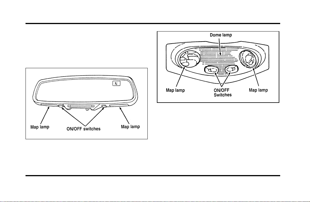
89
Turning On the Lamps
Map Lamps
Your vehicle has a map lamp for the passenger and
one for the driver.
The map lamps on vehicles equipped with a
moon roof
The map lamps on the inside roof of the car
To turn on the map lamps, push the switches in
front of each lamp.
On vehicles equipped with the moon roof option,
the map lamps and switches are located on the
inside rearview mirror.
File:05fncfc.ex
Update:Fri Sep 6 14:53:57 1996
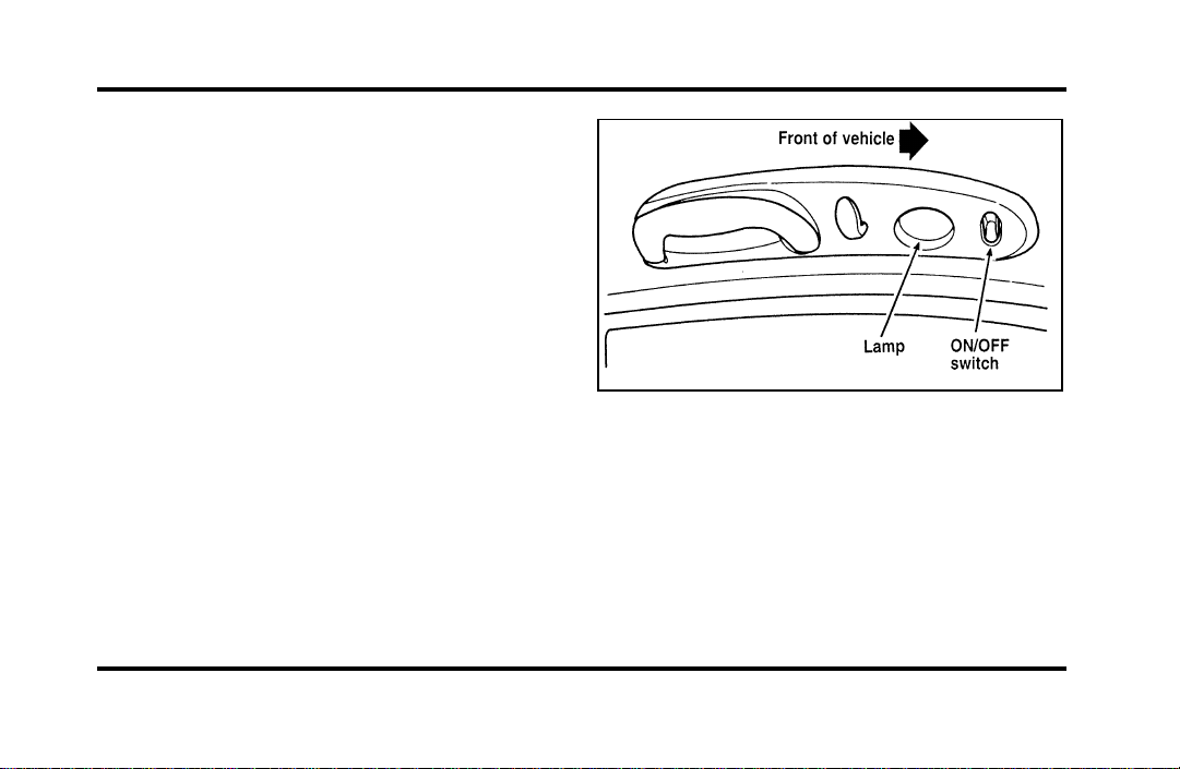
90
Rear Courtesy/Reading Lamps
Your vehicle has two rear passenger
courtesy/reading lamps.
The courtesy lamp lights when any door is opened
or when the instrument panel dimmer switch is
turned to the courtesy lamp position or if either
front door outside handle is lifted with the door
locked.
With the ignition key in the ACC or ON position,
the reading lamp can be turned on by using the
rocker switch on the lamp assembly.
Rear passenger courtesy/reading lamp
File:05fncfc.ex
Update:Fri Sep 6 14:53:57 1996
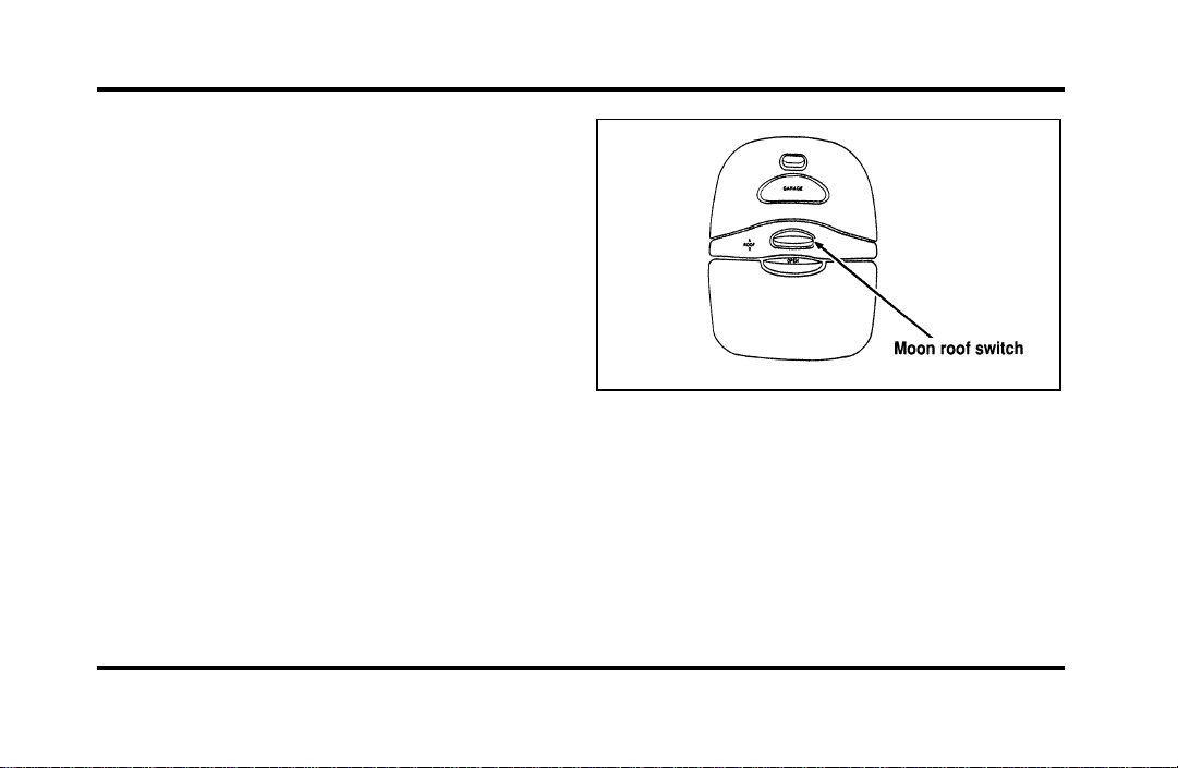
91
Moon Roof (If equipped)
You can move the moon roof back to open the
glass panel, or you can tilt it up to ventilate the
vehicle.
The roof console ROOF switch is used to open and
close the moon roof. Press and hold the switch
until the desired position is reached. At the fully
closed position, the motor automatically turns off.
The switch for the moon roof (overhead
console)
To open the moon roof, push switch rearward.
To close the moon roof, push switch forward.
To tilt the moon roof into vent position when the
glass panel is closed, press and hold the switch
forward.
File:05fncfc.ex
Update:Fri Sep 6 14:53:57 1996
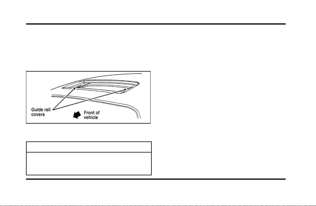
92
Toclosefromventposition,pressandholdthe
switchrearward.
Occasionallywipingtheoutsideguiderailcoversof
themoonroofwithacleanclothwillhelpkeepthe
moonroofworkingproperly.
Themoonroof
WARNING
Donotletchildrenplaywiththemoon
roof.Theymayseriouslyhurt
themselves.
Mirrors
AutomaticDimmingInsideRearview
Mirror(Ifequipped)
Somevehiclesareequippedwithaninsiderearview
mirrorandanoutsidedriver’ssidemirrorwhich
haveanAuto-Dimmingfunction.Theseelectronic
day/nightmirrorswillchangefromthenormalstate
tothenon-glarestatewhenbrightlights(glare)
reachthemirrors.Thesemirrorsfunctionatnight,
andhavealimitedfunctionatduskordawn.From
thenon-glarestate,themirrorswillreturntothe
normalstateafterashortdelay.Thedelaystarts
whenglaregoesaway.Thedelaypreventsexcessive
changingofthemirrorsastrafficmovesbehindand
aroundthevehicle,oronrollinghillsandcurves.
File:05fncfc.ex
Update:Fri Sep 6 14:53:57 1996
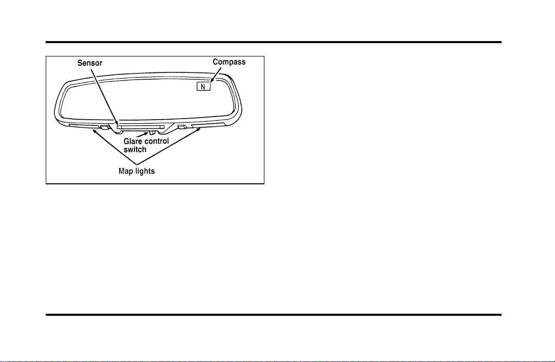
93
The automatic dimming inside rearview mirror
(optional)
The sensitivity level of the mirrors can be adjusted
by moving the switch on the inside rearview mirror
between the OFF and MAX positions. MAX is the
most sensitive setting and bright headlamps far
away will cause the mirrors to automatically darken.
At the setting nearest OFF, bright headlamps will
have to be closer to darken the mirrors. The outside
side mirrors are controlled by the setting on the
inside mirror.
There are two light sensors (photocells) in this
mirror. The sensor that detects rear glare is located
next to the switch. The second light sensor which
determines outside light level is located on the
backside of the mirror case.
One important safety feature is that the mirror
automatically returns to the normal position
whenever the vehicle is placed in R (Reverse)
(when the mirror is in the ON position). This
feature ensures a bright clear view in the mirror
when backing up.
Do not clean the housing or glass of any mirror
with harsh abrasives, fuel or other petroleum-based
cleaning products.
File:05fncfc.ex
Update:Fri Sep 6 14:53:57 1996
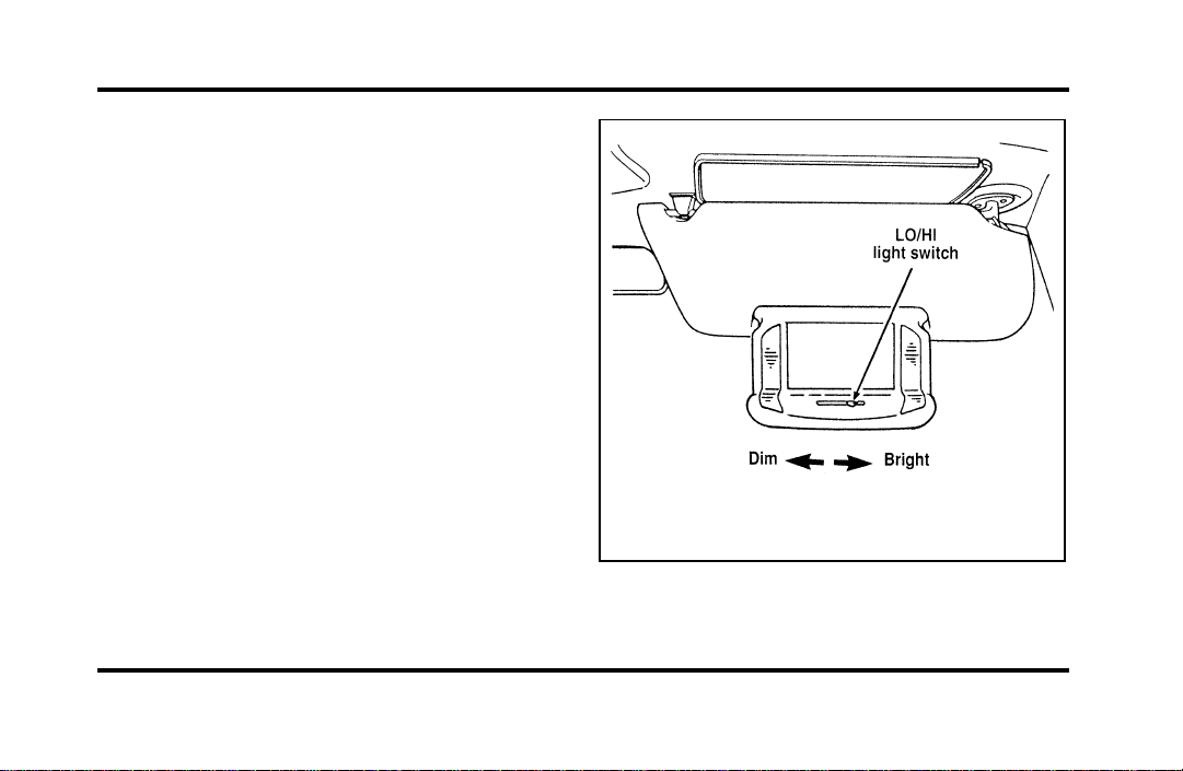
94
Sun Visors
Using the Sun Visors
Your vehicle has special sun visors. Besides the
regular sun visor, you have a second visor. By using
both the regular sun visor and the second visor, you
shield the sun from both the front and the side of
the vehicle at the same time.
To block the sun, move the main visor sideways
and flip the second visor down.
Illuminated Visor Mirror
The illuminated visor mirror slides inside the visor.
To light the mirror, pull down the mirror and slide
switch at bottom of visor. To adjust the amount of
light, slide the switch left for LO (dim) and right for
HI (bright).
The illuminated mirror on the sun visor
File:05fncfc.ex
Update:Fri Sep 6 14:53:57 1996
95
HomeLinkHUniversalTransmitter
(Ifequipped)
TheHomeLinkUniversalTransmitterprovidesa
convenientwaytoreplaceuptothreehand-held
transmitterswithasinglebuilt-indevice.This
innovativefeaturewilllearntheradiofrequency
codesofmostcurrenttransmitterstooperategarage
doorsandgates.Withtheavailableaccessory
package,theHomeLinkTransmittercanalsocontrol
homeorofficelightingandsecuritysystems.For
reliability,theHomeLinkTransmitterispoweredby
yourvehicle’sbatteryandchargingsystem.
WARNING
WhenprogrammingyourHomeLink
Transmitter,youwillbeoperatingthe
garagedoororgate.Besurethatpeople
andobjectsareoutofthewayto
preventpotentialharmordamage.
DonotusethisHomeLinkTransmitterwithany
garagedooropenerthatlackssafety“stop”and
“reverse”featuresasrequiredbyfederalsafety
standards,(thisincludesanygaragedooropener
modelmanufacturedbeforeApril1,1982).Agarage
dooropenerwhichcannot“detect”anobjectinthe
pathofaclosingdoorandthenautomatically“stop”
and“reverse”thedoor,doesnotmeetcurrent
federalsafetystandards.Usingagaragedooropener
withoutthesefeaturesincreasesriskofserious
injuryordeath.Formoreinformationonthis
matter,calltoll-free:1-800-355-3515.
File:05fncfc.ex
Update:Fri Sep 6 14:53:57 1996
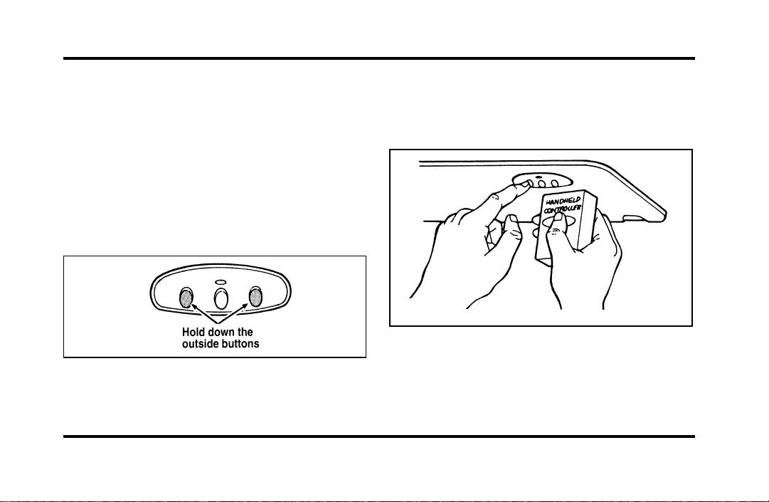
96
Programming
If after repeated attempts you do not successfully
program the HomeLink Universal Transmitter to
learn the signal of the hand-help transmitter, call
toll-free for customer assistance: 1-800-355-3515.
1. If you have previously programmed your
HomeLink Transmitter, proceed to step 2.
Otherwise, hold down the two outside buttons
on the HomeLink Transmitter until the red
light begins to flash. Release both buttons.
2. Decide which one of the three channels you
want to program.
3. Hold the end of your hand-held transmitter
against the front surface of the HomeLink
Transmitter so that you can still see the red
light.
File:05fncfc.ex
Update:Fri Sep 6 14:53:57 1996

97
4. Using both hands, push the hand-held
transmitter button and the desired button on
the HomeLink Transmitter. Continue to press
both buttons through step 5.
5. Hold down both buttons until you see the red
light on the HomeLink Transmitter flash, first
slowly and then rapidly. It indicates that you
have successfully programmed the HomeLink
Transmitter to learn the new frequency signal.
Release both buttons once the rapid flashing
begins.
Note to Canadian Residents
During programming, your hand-held transmitter
may automatically stop transmitting after two
seconds, which may not be long enough to program
the HomeLink Universal Transmitter.
If you are programming from one of these
hand-held transmitters, continue to hold the button
on the HomeLink Transmitter while you re-press
your hand-held transmitter every two seconds.
You may have to repeat this function several times
while programming.
Operating the HomeLinkH Universal
Transmitter
Once it is programmed, the HomeLink Universal
Transmitter can be used in place of your hand-held
transmitter(s). To operate, simply press the
appropriate button on the HomeLink Transmitter.
The red light comes on while the signal is being
transmitted.
NOTE: If your hand-held transmitter appears to
program the HomeLink Transmitter, but does not
open your garage door, and if your garage door
opener was manufactured after 1995, your garage
door opener may have a “code protected” or
“rolling code” feature.
A “rolling code” type of system will change the
“code” of your garage door opener every time you
open or close your garage door.
File:05fncfc.ex
Update:Fri Sep 6 14:53:57 1996

98
To determine if you have one of these systems,
depress the button on the HomeLink Transmitter
that you programmed. If the red light on the
HomeLink Transmitter flashes rapidly for 1-2
seconds, then remains on, your garage door opener
has a rolling code system.
Training a Garage Door Opener
Equipped with “Rolling Codes”
To train your “rolling code” garage door opener to
operate from your HomeLink Transmitter, follow
these steps:
1. Program your hand-held transmitter to the
HomeLink Transmitter by following the
procedures outlined in the “Programming”
section of these instructions. (If you already
completed this programming, proceed to the
next instruction.)
2. Train your garage door opener receiver to
recognize your HomeLink Transmitter. (Your
garage door opener receiver will learn to
recognize the HomeLink Transmitter by
following the same procedures used to train the
hand-held transmitter.)
❑
Remove the cover panel from your garage door
opener receiver. (The receiver should be located
by the garage door opener motor.)
❑
Locate the training button on the garage door
opener receiver. The exact location and color of
the button may vary by garage door opener
brand. If you have difficulty locating the training
button, reference your garage door opener
manual, or call 1-800-355-3515.
❑
Press the training button on the garage door
opener receiver for 1-2 seconds.
File:05fncfc.ex
Update:Fri Sep 6 14:53:57 1996

99
❑
Return to the HomeLink Transmitter in the
vehicle, and depress the programmed HomeLink
button for the duration of the rapid flash of the
HomeLink’s red light, (1-2 seconds). Release the
button, and re-press the button to confirm that
the HomeLink Transmitter has been trained to
the receiver.
❑
Your garage door opener should now recognize
your HomeLink Transmitter. You may use either
your HomeLink Transmitter or your original
hand-held transmitter to open your garage door.
If after following these suggestions you still have
difficulties in programming your HomeLink
Transmitter, call toll-free for customer assistance:
1-800-355-3515.
Erasing Channels
To erase all three programmed channels, hold down
the two outside buttons until the red light begins to
flash. Then release both buttons. Individual channels
cannot be erased, but can be reprogrammed using
the procedures for programming the HomeLink
Transmitter, (steps 2 through 5).
NOTE: Be sure to retain your original transmitter
for future programming procedures (i.e., new
vehicle purchase).
NOTE: When selling your vehicle, be sure to erase
all channels on the HomeLink Transmitter that you
programmed.
Accessories
Accessories for your HomeLink Universal
Transmitter are available from the manufacturer of
the device. If you would like additional information
or would like to purchase other accessories such as
home lighting or security products that can be
operated by the HomeLink Universal Transmitter,
please call toll-free: 1-800-355-3515.
File:05fncfc.ex
Update:Fri Sep 6 14:53:57 1996
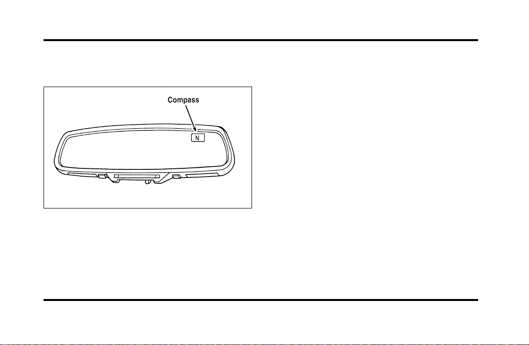
100
The Electronic Compass
(If equipped)
The electronic compass
The compass is mounted to the inside rear view
mirror. The display is in the upper right hand
corner of the mirror glass.
The display will show one of the following
directions: N, NE, E, SE, S, SW, W, and NW. The
brightness of the compass display is controlled by
the instrument panel dimming switch.
Factors Affecting Compass Accuracy
Some things which can affect compass accuracy are
large buildings, bridges, power lines, and powerful
antennas. Keep radar detectors and other
magnetically mounted devices as far away from the
compass as possible. Sometimes after-market and
dealer-installed moon roofs can affect the accuracy
of the compass. Using automatic car washes can
cause minor inaccuracies in the compass.
NOTE: Usually, when something affects the
compass readings, the compass will correct itself
after a few days of operating your vehicle in normal
conditions. If the compass is still giving inaccurate
readings after a few days, perform a compass
adjustment.
File:05fncfc.ex
Update:Fri Sep 6 14:53:57 1996

101
Compass-Calibration
1. For optimum calibration, switch off all
non-essential electrical accessories (rear window
defrost, heater/air conditioning, map lamps,
wipers, etc.) and ensure all doors are shut.
2. Drive to an open, level area away from large
metallic objects or structures.
3. Insert an appropriate diameter rod (paper clip)
into the left switch access hole underneath the
compass module and press gently for 1-2
seconds until “CAL” and a direction appear on
the display.
4. Release the button and drive in a circle until
“CAL” disappears from the display (approx. 2-3
circles).
Compass-Zone Adjustment
1. The zone setting is factory pre-set to Zone 8.
Refer to the Zone Map in this manual to verify
the correct compass zone setting for your
geographical location.
File:05fncfc.ex
Update:Fri Sep 6 14:53:57 1996
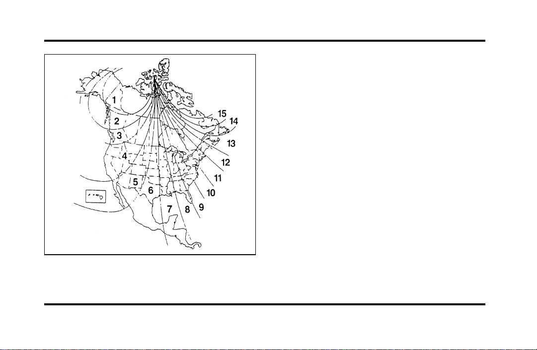
102
2. Insert an appropriate diameter rod (paper clip)
into the right switch access hole underneath
the compass module and gently press the right
button for 1-2 seconds until “ZONE” and the
current zone setting appear in the display.
3. Release the right button.
4. Pressing the right button repeatedly will cycle
through all possible zone settings. Stop cycling
when the correct zone setting for your location
appears.
5. Releasing the button for 2 seconds will exit the
zone entry mode.
File:05fncfc.ex
Update:Fri Sep 6 14:53:57 1996
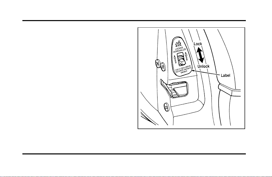
103
Doors
Childproof Locks for the Rear Doors
In addition to power locks, your vehicle has
childproof locks for the rear doors. If you set these
locks, the rear doors cannot be opened from the
inside of the vehicle. The doors can still be opened
from the outside when the lock knobs are raised.
The childproof locks for the rear doors
File:05fncfc.ex
Update:Fri Sep 6 14:53:57 1996
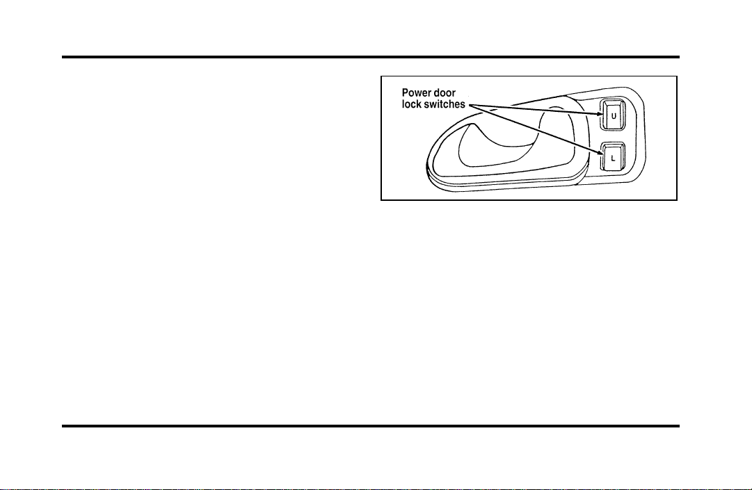
104
To set the childproof lock on each rear door, open
the rear door.
Find the lever at the black label with the word
LOCKED in white letters. Move the lever up.
To release the childproof lock, open the rear door
from the outside and move the lever down.
Using the Power Door Locks
Your vehicle has power door locks. The controls to
lock the doors are on the trim panel of the front
door. When you close the doors after you set the
door locks, the doors remain locked. If the power
mechanism ever fails, the manual door lock will
override the power controls.
The power locks on the driver’s door
Smart Locks
The Smart Locks feature helps prevent you from
locking the keys in your vehicle. With the key in
the ignition (in any switch position) and either the
driver’s or passenger’s door open, the doors cannot
be locked using the front door lock switches.
NOTE: Your vehicle can still be locked, while the
key is in the ignition, by manually pressing down
the lock button or with remote/keyless entry.
File:05fncfc.ex
Update:Fri Sep 6 14:53:57 1996
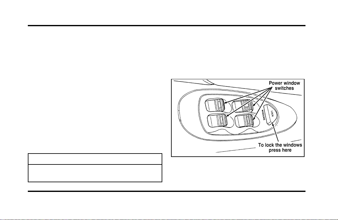
105
IlluminatedEntrySystemwithTheater
Lighting
Theinteriorlightswillilluminateforapproximately
25secondswhenanybuttononthekeylessentry
padispressedortheremoteentrysystemUNLOCK
buttonispushed.
UsingthePowerWindows
Eachdoorhasapowercontrolthatopensand
closesthewindowonthatdoor.Thedriver’sdoor
hasamastercontrolpanelthatoperatesallfour
windows.
Powerwindowscanonlybeopenedorclosedwhen
theignitionisintheONorACCpositionorduring
thetenminutedelayedaccessoryperiodafterthe
ignitionisturnedoff.
WARNING
Donotletchildrenplaywiththepower
windows.
NOTE:Yourvehicleisalsoequippedwitha
delayedaccessorytimer.Thisallowssomeofyour
accessoriestoremainonforupto10minutesafter
thekeyisturnedtotheOFFposition.The
accessorytimeriscancelledifanydoorisopenedor
thekeyisturnedtotheONposition.
Themastercontrolsonthedriver’sdoor
File:05fncfc.ex
Update:Fri Sep 6 14:53:57 1996

106
To lock out all window switches except the master
controls, press the window lock switch once. To
restore control to the individual windows, press the
switch again.
There is also an Express Down feature on the
driver’s power window. This feature can be
activated through the menu functions of your
Message Center.
To operate, briefly press the driver’s window switch
to the down position. The window will then open
automatically. To stop automatic operation, briefly
press the switch again to either the up or down
position. More than a quick press of the switch
provides conventional power window operation.
Closing of the power window is conventional
operation only.
Memory Profile System
(If equipped)
The Personality Memory Feature customizes your
Continental for up to two (2) drivers. The following
features are automatically recalled when unlocking
the doors using the remote entry transmitter,
keyless entry keypad, or by pressing the Memory 1
or Memory 2 switches on the driver’s door:
❑
All driver’s seat positions except power lumbar
and head restraint.
❑
Both left and right outside mirror settings.
❑
Radio station presets including the last selected
station and band and all preset preferences on
FM1, FM2, and AM.
❑
Instrument panel dimming setting.
❑
Autolamp delay time-out setting.
❑
Ride/Steering menu setting.
❑
Feature Menu settings
File:05fncfc.ex
Update:Fri Sep 6 14:53:57 1996

107
The Ride/Steering menu is located in the Message
Center. The RIDE display allows you to adjust the
suspension feel to FIRM, NORMAL, or PLUSH.
Pressing the Ride/Steering menu switch again brings
the STEERING display. This allows you to adjust
steering effort to LOW, NORMAL, or HIGH.
For more information on ride/steering options, see
Road Calibrated Suspension later in this chapter.
Personality Memory also allows you to customize
settings from the Feature menu located in the
Message Center. The Feature menu contains five (5)
features that you can enable or disable. The features
are listed in the order they appear in the Feature
menu.
❑
EXPRESS WINDOW - for one tap down
operation of the driver’s window.
❑
AUTO DOOR LOCKS - automatically locks all
doors when the driver shifts out of PARK, all
doors are closed, and the vehicle speed is at
least three mph (five km/h).
❑
HORN CHIRP - sounds an audible “chirp”
when you press the LOCK button on the
remote entry transmitter to verify that the doors
have been locked and the vehicle’s anti-theft
system has been armed (if equipped).
❑
SEAT ACCESS - moves the driver’s seat back
two (2) inches or to the end of the seat track
when the vehicle is turned off and the ignition
key is removed. Upon the driver entering the
vehicle and closing the door, the seat will move
forward to its previous position.
File:05fncfc.ex
Update:Fri Sep 6 14:53:57 1996

108
❑
REVERSE MIRROR - when the vehicle is shifted
to REVERSE, the outside rearview mirrors tilt
down. This provides an improved view of the
side of the vehicle and curb area when backing
up. When you shift out of REVERSE, the
mirrors return to their previous positions.
Recalling Personality Memory
All of these settings are automatically recalled when
the driver unlocks the door using the remote entry
transmitter, keyless entry keypad or presses either
Memory 1 or Memory 2 switch inside the driver’s
door. The vehicle must be in PARK or NEUTRAL to
recall Personality Memory settings.
Remote Entry
Pressing the UNLOCK button on the remote entry
transmitter unlocks the driver’s door and recalls all
of the Personality Memory settings. Two
transmitters are delivered with the vehicle. One is
programmed to always recall Memory 1 and the
other will always recall Memory 2. Personality
Memory 1 or 2 is indicated on the back of the
transmitter.
Personality Memory recall from the remote
transmitter can be disabled. This is done by sliding
the switch on the back of the transmitter to OFF.
Personality Memory can still be recalled using
keyless entry code or the Memory 1 or Memory 2
switches.
Keyless Entry
Up to three unique keyless entry codes can be
programmed by the customer. Two of the codes
can be assigned to recall Personality Memory 1 or
Memory 2. Each time the 5-digit code is entered on
the keypad, the driver’s door will unlock and
Personality Memory 1 or Memory 2 will be
recalled.
File:05fncfc.ex
Update:Fri Sep 6 14:53:57 1996

109
NOTE: Please note that even though the driver’s
Personality Memory may be recalled using remote
or keyless entry, the seats and mirrors will not
move to the driver’s set positions until the driver’s
door is opened.
Memory Switches
Pressing either the Memory 1 or Memory 2 switch
on the driver’s door will also recall the Personality
Memory settings as selected, providing your vehicle
is in P (Park) or N (Neutral).
Auto Save
Any change made by the driver to one of the above
Personality Memory settings will be updated and
saved automatically. The display, SAVED TO
DRIVER 1 or SAVED TO DRIVER 2, will appear on
the Message Center for five (5) seconds as a
confirmation of the update to Personality Memory.
If a radio preset is changed the radio display will
also show SAVED.
If the driver does not use the remote entry
transmitter, or keyless entry keypad to unlock the
doors upon entering or does not press the Memory
1 or Memory 2 switch, then any change to one of
the Personality Memory settings (except radio
presets) will not be automatically saved. Instead the
driver will be prompted by the Message Center
whether to save the settings to Driver 1 or Driver
2.
Pressing the SELECT switch will toggle between 1,
2 or no choice. If DRIVER 1 or DRIVER 2 is
selected, the display, SAVED TO DRIVER 1 or
SAVED TO DRIVER 2, will appear on the Message
Center to confirm the change has been
automatically saved with the Personality Memory. If
no choice is made by the driver, then the change
will not be automatically saved and there is no
effect on the Personality Memory.
Once this screen has been displayed, the driver will
not be asked again for the remainder of the drive.
File:05fncfc.ex
Update:Fri Sep 6 14:53:57 1996
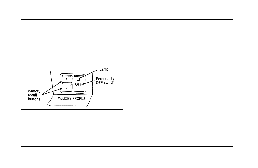
110
Turning Personality OFF
The Personality Memory feature can be turned off
using the Memory OFF switch on the driver’s door.
The amber indicator light will be lit when the
feature is turned OFF. Pressing either the Memory
1 or Memory 2 switch will turn on the Personality
Memory feature and recall the saved settings.
The Memory Profile System buttons
When Personality is OFF, the vehicle will function
as if the Personality Memory feature was not on the
vehicle. Also, when a change is made to one of the
Personality settings, there will be no prompts on the
Message Center asking which driver to save the
setting to.
Side View Mirrors
Your vehicle comes with electric side mirrors. The
side view mirror on the right is a convex mirror.
This mirror gives you a wider view of the lanes on
your right and behind you.
NOTE: When putting your vehicle in reverse, both
outside mirrors will tilt downward and return to the
adjusted position when taken out of reverse. This
feature can be disabled by using the Menu Select
button on the cluster. To disable, press the menu
button repeatedly until “Reverse Mirrors” appears in
the display, then select OFF. To enable the reverse
mirrors, select ON.
File:05fncfc.ex
Update:Fri Sep 6 14:53:57 1996
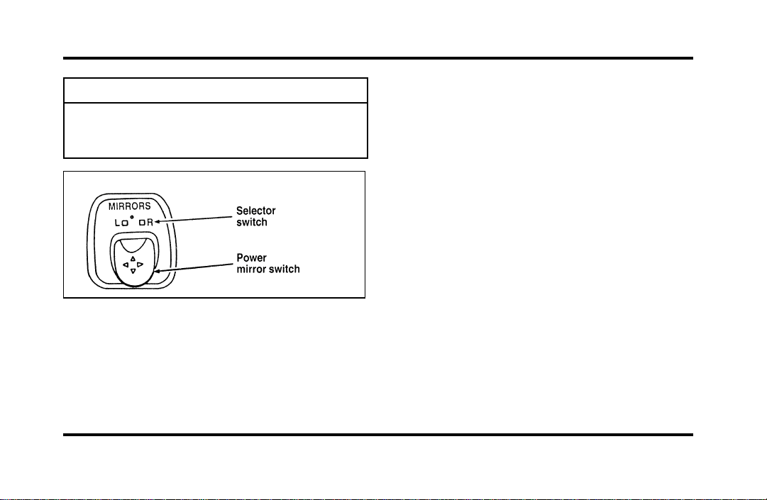
111
WARNING
Therightsideviewmirrormakes
objectsappearsmallerandfartheraway
thantheyactuallyare.
Theelectricremotecontrolmirrorswitch
Toadjustthesidemirrors:
1. Findthecontrolswitchinthedriver’sdoor
panel.
2. Selecttherightorleftmirrorbymovingthe
selectorswitchtoRorL.
3. Movethemirrorswitchinthedirectionyou
wanttomovethemirror.
4. Returntheselectorswitchtothemiddle
positiontokeepthemirrorinplace.
Donotcleanthehousingorglassofanymirror
withharshabrasives,fuelorotherpetroleum-based
cleaningproducts.
File:05fncfc.ex
Update:Fri Sep 6 14:53:57 1996
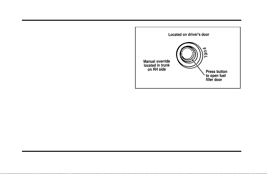
112
Heated Mirror Feature
Both mirrors are heated whenever the Electric Rear
Window Defroster is turned on. Do not remove ice
from the mirrors with a scraper or you could
damage them. If the outside mirror glass is frozen
in place, do not attempt to readjust or move the
mirror glass or damage may result.
Remote Control Fuel Filler Door
Release Button
Your vehicle has a remote control fuel filler door
which cannot be opened from outside of the
vehicle. To unlatch the fuel filler door, push the
fuel door button on the driver side door. Refer to
theMaintenance and Care chapter for further
information.
The remote control fuel filler door release
button
File:05fncfc.ex
Update:Fri Sep 6 14:53:57 1996
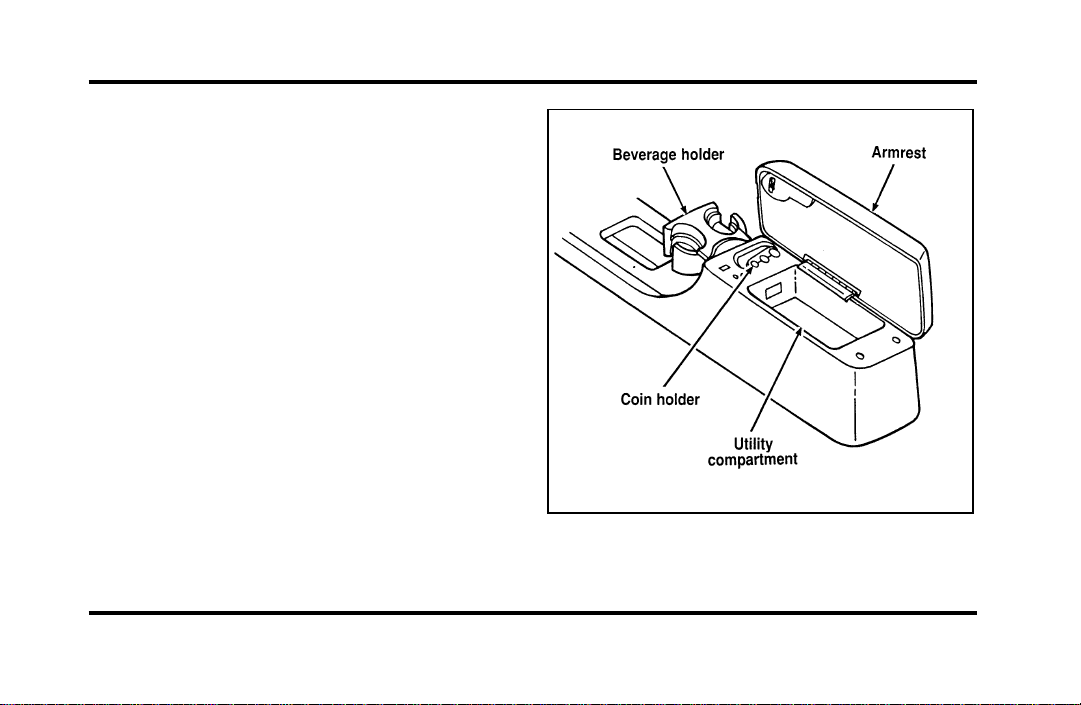
113
Cellular Phone (If equipped)
For information about the cellular phone in your
vehicle, refer to the Cellular Phone User’s Manual
provided with your phone. For further questions
about your Lincoln cellular phone, contact the Ford
Cellular System at 1-800-367-3013(U.S.). In
Canada, please contact your dealer.
NOTE: It is recommended that you fold your
cellular phone antenna down onto the back glass
before entering a car wash.
Console
Your vehicle may have a full console. The full
console has the following features:
The features on the full console
File:05fncfc.ex
Update:Fri Sep 6 14:53:57 1996
114
CupholderWithFullConsole
Thecupholderprovidesaspaceforyourcup.
Miniconsolecupholders
Sixpassengervehiclesareequippedwithamini
consolethatislocatedwithintheashtraypanel.To
openthepanel,pressonthefrontofitandrelease.
Itwillopenautomatically.Toclose,pushthepanel
backintoplaceuntilitlatches.
WARNING
Useonlysoftcupsinthecupholder.
Hardobjectscaninjureyouina
collision.
PositiveRetentionDriver’sSide
FloorMat
InstallingtheFloorMat
Positionthefloormatinfootwell.Placemateyelet
overpointedendofretentionpostfromtherear
androtateforwardtoinstall.Adjustfloormat
positiontoallowproperoperationofaccelerator
pedalandbrakepedal.
File:05fncfc.ex
Update:Fri Sep 6 14:53:57 1996
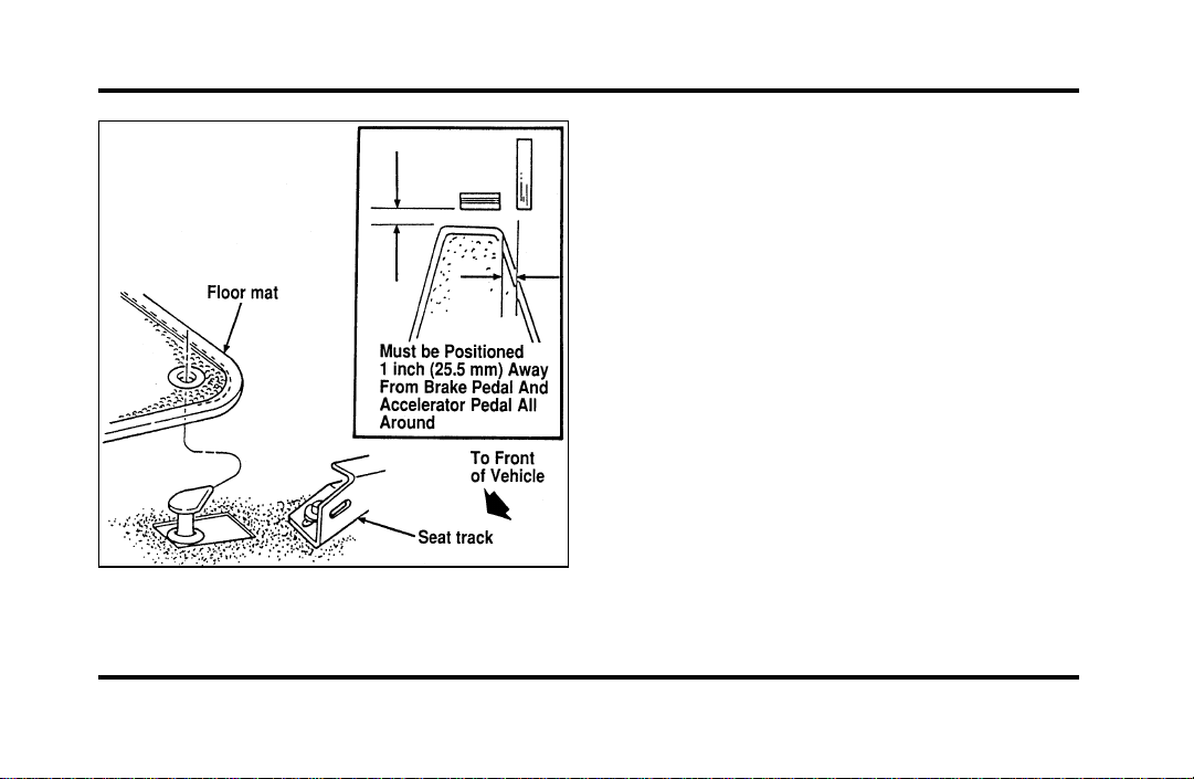
115
The positive retention floor mat
Removing the Floor Mat
Lift floor mat just forward of retention post and
rotate rearward to disengage from retention post.
File:05fncfc.ex
Update:Fri Sep 6 14:53:57 1996
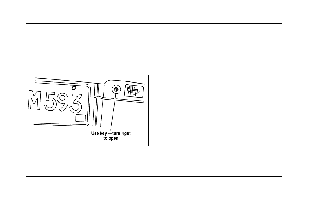
116
Trunk
Opening the Trunk Manually
Locate the trunk lock in the rear reflector to the
right of the license plate to insert the key. Turn the
key to the right to open the trunk.
The trunk lock cylinder
Using the Power Trunk Release
You can use your power trunk release feature in
three ways:
With your electric trunk release, you can open the
trunk from inside your vehicle by pressing the
TRUNK RELEASE button located on the driver side
door. The TRUNK RELEASE button will only
function when the vehicle is traveling under three
mph (five km/h).
To open your trunk with the keyless entry system,
press 5/6 on the keyless entry pad within five
seconds of entering the keyless code.
You can also open the trunk by pressing the
TRUNK button on the remote entry transmitter. To
prevent inadvertant activation, the trunk button
must be depressed twice within five (5) seconds to
open the trunk.
File:05fncfc.ex
Update:Fri Sep 6 14:53:57 1996
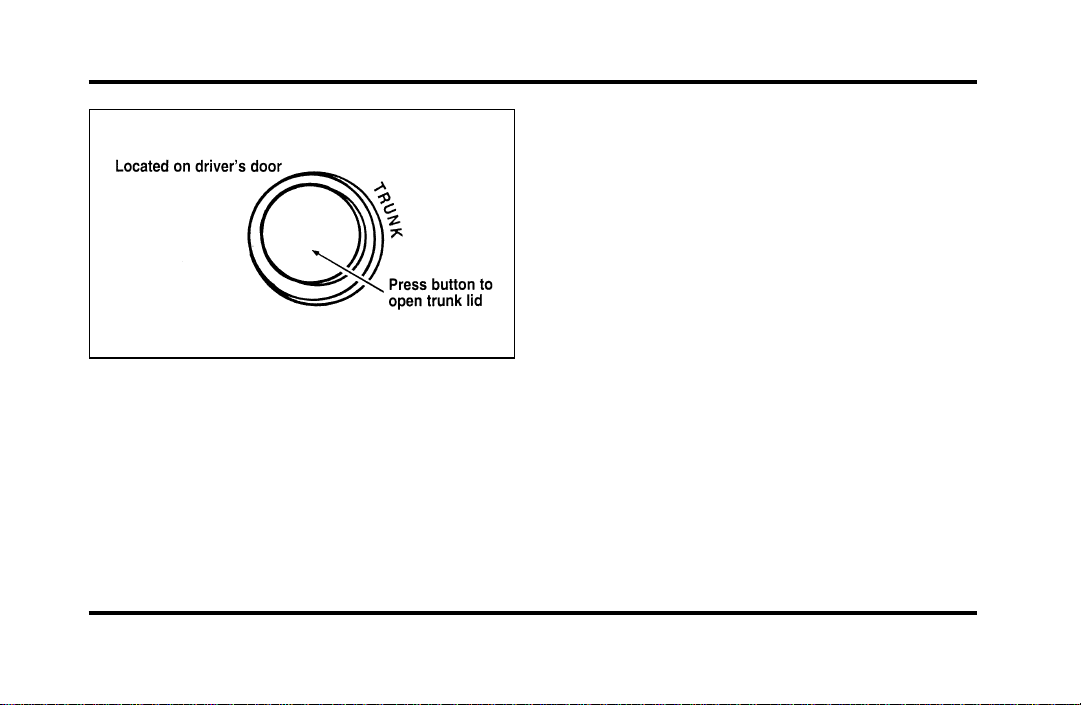
117
The remote control for the trunk
The trunk lid cannot be opened if your vehicle is
moving faster than three mph (five km/h).
Cargo Storage System
(If equipped)
Your vehicle may be equipped with a cargo storage
system. It was designed to allow you to use all
available space in your trunk while permitting easy
loading and unloading.
File:05fncfc.ex
Update:Fri Sep 6 14:53:57 1996
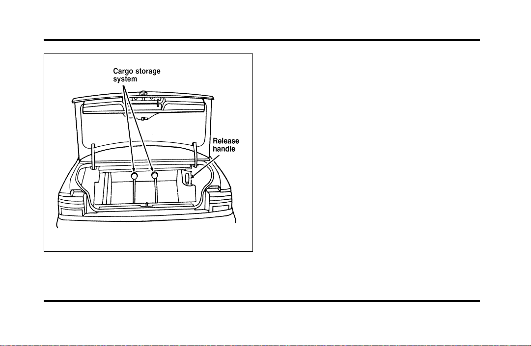
118
The cargo storage system
To operate:
1. Grasp and squeeze the release handle to move
the cargo storage system rearward.
2. Place groceries, packages, etc. in the cargo
storage system.
3. Grasp and squeeze the release handle to move
the cargo storage system forward until it locks
into place.
NOTE: The cargo storage system has three locking
positions. Make sure the storage system is securely
locked in place.
Keyless Entry System
You can lock or unlock the vehicle doors and open
the trunk without using a key. The buttons for the
system are below the outside door handle on the
driver’s side. See also Remote Entry System which
follows this description.
File:05fncfc.ex
Update:Fri Sep 6 14:53:57 1996
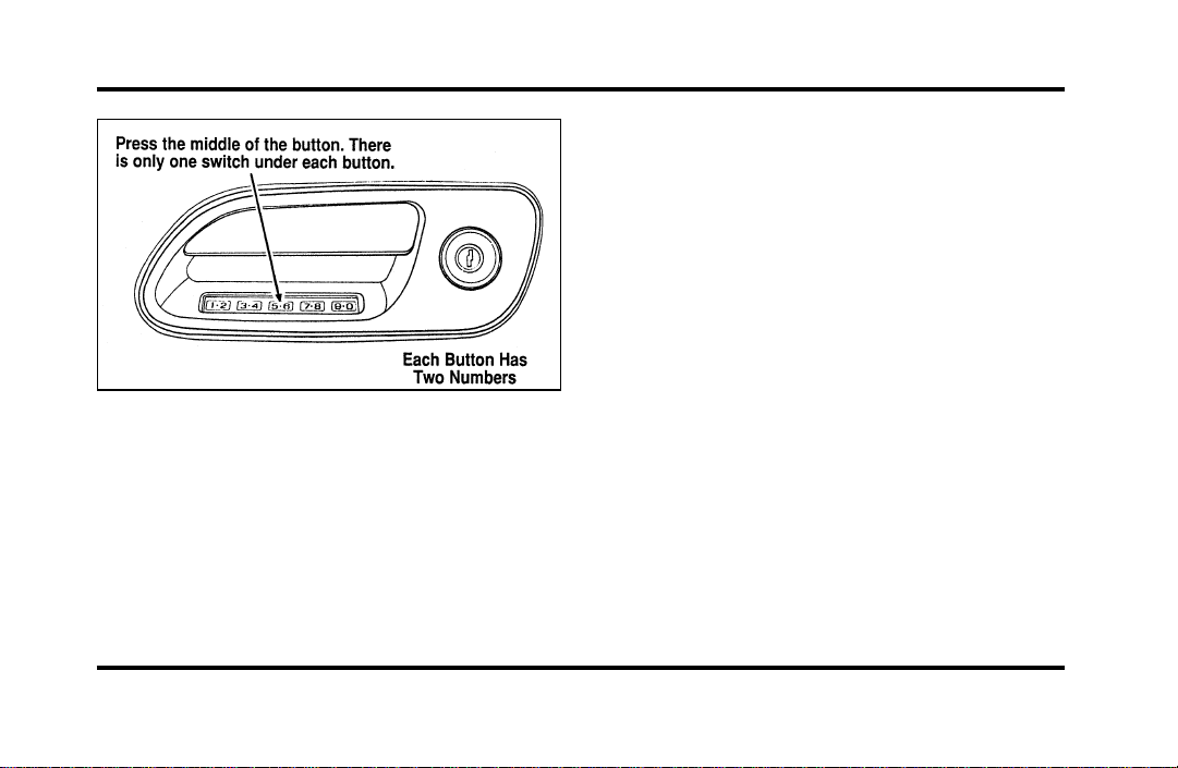
119
The keyless entry buttons
When you bought your vehicle, you were given a
computer code that operates the system for your
vehicle. For your convenience, we have duplicated
this code in three places.
The code is:
❑
on your owner’s wallet card found in the glove
compartment
❑
taped to the trunk lid’s right hinge support bar
❑
taped to the computer module in your driver’s
front door
When you use keyless entry, the illuminated entry
system turns on the interior lights for 25 seconds
and the buttons on the keypad light up. Do not
push the buttons with a key, ballpoint pen, pencil,
or any other hard object. These objects could
damage the buttons.
Unlocking the Doors with the Keyless
Entry System
You must unlock the driver’s door before you
unlock any of the other doors or trunk. If you let
more than five (5) seconds pass before pressing
numbers, the system shuts down, and you have to
enter the code again. The system has shut down if
the keypad light is out. If the keyless entry system
does not work properly, use the key or
transmitter(s) to lock and unlock the doors or
unlock the trunk.
File:05fncfc.ex
Update:Fri Sep 6 14:53:57 1996

120
1. To unlock the driver’s door, enter the factory
code or your personal code. All codes have five
(5) numbers. After you press the fifth number,
the driver’s door unlocks.
2. To unlock all passenger doors, press the 3/4
button within five (5) seconds of unlocking the
driver’s door or trunk, or re-enter the code to
open the driver’s door, then press 3/4.
3. To unlock the trunk, press the 5/6 button
within five seconds of unlocking the driver’s or
passenger’s doors, or re-enter the code to open
the driver’s door, then press 5/6.
As long as the driver’s door has been unlocked first,
you can open the passenger door or the trunk in
any order.
Locking the Doors with the Keyless
Entry System
Along with unlocking your doors, you can use the
keyless entry system to lock the doors.
To lock all of the vehicle’s doors at the same time,
press 7/8 and 9/0 at the same time. It is not
necessary to first enter the keypad code. This will
also arm your anti-theft system (if equipped).
Autolock
The Autolock feature will automatically lock all the
doors when:
❑
the vehicle’s doors are fully closed
❑
the ignition key is turned to the ON position
❑
someone is sitting in the driver’s seat or a
heavy object is placed on it
❑
the vehicle is in a forward gear, and
❑
you exceed three mph (five km/h).
File:05fncfc.ex
Update:Fri Sep 6 14:53:57 1996

121
The Autolock feature will repeat when:
❑
the ignition key remains in the ON position
❑
someone remains sitting in the driver’s seat or a
heavy object is on the seat
❑
a door is opened and then closed
❑
the vehicle is in a forward gear, and
❑
you exceed three mph (five km/h).
If you do not want to use the Autolock feature, it
can be deactivated by using the Feature Menu in
the Message Center.
Programming Your Own Entry Code
You can program up to three personal codes to
unlock your vehicle. These codes do not replace the
permanent code that the dealership gave you. Use
your personal code in the same manner as you
would your original code.
To program your own code:
1. Select five digits for your personal code.
2. Enter the factory code that the dealership gave
you.
3. Within five (5) seconds, press 1/2.
4. Within five (5) seconds of pressing 1/2, enter
your personal code, pressing each digit within
five (5) seconds of the previous digit.
5. Enter a sixth digit to indicate which Personality
should be recalled by this personal code.
1/2 Recall Personality 1
3/4 Recall Personality 2
9/0 No recall
All of the vehicle doors will lock and then
unlock to confirm programming of the new
code.
File:05fncfc.ex
Update:Fri Sep 6 14:53:57 1996

122
The keyless entry system registers this new code.
To open your vehicle, you can now use either code.
To erase all of the personal entry codes and remote
entry transmitters programmed to a vehicle:
1. Enter the original permanent code.
2. Press 1/2 within five seconds of Step 1.
3. Press and hold 1/2 for two (2) seconds.
All of the vehicle doors will lock and then
unlock to confirm erasure.
Do not set a code that presents the numbers in
sequential order, such as 1/2, 3/4, 5/6, 7/8, 9/0.
Studies show that people who idly press the buttons
usually press a sequential pattern. Also, do not
select a code that uses the same button five times.
Thieves can easily figure out these types of codes.
Arming, disarming and resetting your
anti-theft system (If equipped) from the
keyless entry pad
If your vehicle is equipped with the optional factory
installed anti-theft system, the keyless entry system
will arm it when you use the 7/8 and 9/0 keys to
lock the doors, and will disarm or reset a triggered
anti-theft alarm when you enter in the five digit
code to unlock the driver’s door.
Remote Entry System
With the remote entry system, you can lock and
unlock the vehicle doors and open the trunk
without using a key. The buttons for the system are
located on the two hand held transmitters that
came with your vehicle. The remote also has a
personal alarm feature.
The system will work with up to four transmitters.
Your vehicle came with two transmitters. Additional
transmitters can be ordered from your dealer.
File:05fncfc.ex
Update:Fri Sep 6 14:53:57 1996
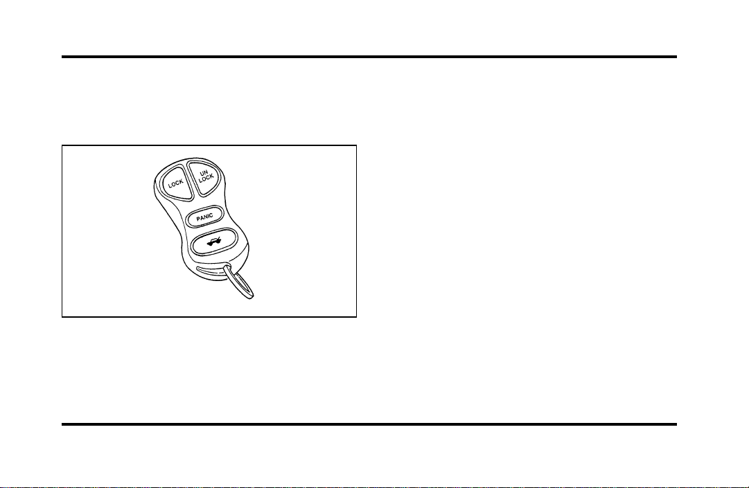
123
The personal alarm feature operates only with the
ignition off. The LOCK, UNLOCK and TRUNK
features work whenever your vehicle is in Park or
Neutral.
Remote entry transmitter
Unlocking the doors and opening the
trunk
To unlock the driver’s door, press the UNLOCK
control.
To unlock the other doors, press the UNLOCK
control a second time within five (5) seconds of
unlocking the driver’s door.
To open the trunk, press the TRUNK control twice
within five (5) seconds.
Locking the doors
To lock all the doors, press the LOCK control. This
will also arm the anti-theft system (if equipped).
A programmable door lock horn chirp can be
activated through the message center. Once
activated, every depression of the LOCK control will
cause the vehicle to honk its horn briefly.
File:05fncfc.ex
Update:Fri Sep 6 14:53:57 1996

124
Activating the remote personal alarm
If you wish to activate the remote personal alarm,
press the PANIC control. This will honk the horn
and flash the parking lamps and tail lamps for
approximately two minutes and forty-five seconds.
You can turn it OFF by pressing the PANIC control
again or by turning the ignition key to the RUN
position.
Arming and Disarming the Alarm
System
If your vehicle is equipped with the factory installed
anti-theft system, the remote entry system will
automatically arm it when the doors are locked
with the remote entry LOCK control. The remote
entry UNLOCK control will disarm or reset a
triggered anti-theft alarm.
The remote entry system is designed to work with
the factory installed anti-theft system. It may not
work with other anti-theft systems.
Replacing the Batteries
The remote entry transmitter is powered by two
coin type three-volt lithium 1616 batteries
(included) that should last for several years of
normal use. If you notice a significant decrease in
operating range, the batteries should be replaced.
Replacement batteries can be purchased at most
pharmacies, watch stores or at your Ford or
Lincoln-Mercury dealer.
NOTE: The operating range of the remote entry
system can also be affected by weather conditions
(such as very cold temperatures) or structures
around the vehicle (buildings, other vehicles, radio
and TV towers, etc.). Typical operating range will
allow you to be up to 33 feet (10 meters) away
from your vehicle.
The transmitter can be snapped apart to replace the
batteries by twisting a thin coin between the two
halves of the transmitter. DO NOT TAKE THE
FRONT PART OF THE TRANSMITTER APART.
File:05fncfc.ex
Update:Fri Sep 6 14:53:57 1996

125
When installing the new batteries, be sure to place
the positive (+) side down as marked. Snap the two
halves back together.
Replacement/additional transmitters
In the event a transmitter is lost, a new one may
be purchased from your dealer.
To program replacement or additional transmitters
you must have all the transmitters intended for use
on your vehicle.
Initiating the following procedure erases all prior
programmed transmitters, thus ALL must be
reprogrammed at the same time.
1. Enter the factory keyless entry code. Your
personal code will not allow programming.
2. Press the 1/2 button.
3. Press one button on each of the transmitters to
be programmed. Each transmitter button must
be pressed within seven (7) seconds of the
prior one. Each time a transmitter is
successfully programmed, all of the vehicle
doors will lock and then unlock to verify
programming. If the doors did not lock/unlock,
your transmitter was not programmed.
Additional transmitters may be purchased from your
dealer (remote entry system will work with up to
four transmitters). Follow the same programming
procedure as above.
THIS DEVICE COMPLIES WITH PART 15 OF
THE FCC RULES. OPERATION IS SUBJECT TO
THE FOLLOWING TWO CONDITIONS: (1)
THIS DEVICE MAY NOT CAUSE HARMFUL
INTERFERENCE, AND (2) THIS DEVICE MUST
ACCEPT ANY INTERFERENCE RECEIVED,
INCLUDING INTERFERENCE THAT MAY
CAUSE UNDESIRED OPERATION.
File:05fncfc.ex
Update:Fri Sep 6 14:53:57 1996

126
NOTE: All transmitters to be used on your vehicle
must be programmed/reprogrammed at the same
time.
Battery Saver
When the ignition is turned off, the vehicle will
turn off battery voltage to the interior lights after 45
minutes.
This will prevent draining of the battery if those
lights have been left on inadvertently or if a door is
not completely closed. Battery voltage to these
lamps will be restored when the keyless entry
keypad is used, the remote entry transmitter is
used, any door is opened, the trunk is opened, or
the ignition key is turned to the ON position.
Anti-theft System
When armed, this system helps protect your vehicle
against break-ins or theft by monitoring all doors,
the hood, and the trunk lock cylinder.
When an unauthorized entry occurs, the system
triggers and will:
❑
flash the headlamps, parking lamps, interior
lamps, and alarm indicator light
❑
honk the horn
❑
prevent the engine from starting
NOTE: The factory installed Remote Entry System
has a PANIC feature that also chirps the vehicle
horn and flashes the interior/exterior lamps when
the PANIC button on the remote entry transmitter
is pushed. The PANIC alarm and the Anti-Theft
alarm are two separate features. Both the
anti-theft alarm and the PANIC feature can be
active at the same time.
File:05fncfc.ex
Update:Fri Sep 6 14:53:57 1996

127
To tell the difference between a PANIC alarm and
a triggered Anti-Theft alarm:
❑
only the Anti-Theft alarm will cause the alarm
indicator light (located in the center of the
instrument cluster) to flash on and off.
❑
only the Anti-Theft alarm will prevent the
engine from starting.
For more information on the PANIC alarm, see
Remote Entry System in the Index.
Arming the System
To arm the system, do the following four steps in
sequence.
1. Remove the key from the ignition.
2. Open any door. The alarm indicator light will
start flashing to remind you to arm the system.
3. Lock the doors by using the power door lock
switch, pressing the remote entry transmitter
LOCK control or pressing the last two buttons
(7/8, 9/0) of the keyless entry keypad.
The alarm indicator will now glow steadily.
4. Close all doors. The alarm indicator light will
then remain on steadily for approximately 30
more seconds and then go out. When the light
goes out the system is armed.
NOTE: Be sure to close all doors completely. If
not, the alarm indicator light will remain on.
Remember, your anti-theft system is armed only
after the alarm indicator light remains on steadily
for approximately 30 seconds after the last door is
closed, and then goes out.
File:05fncfc.ex
Update:Fri Sep 6 14:53:57 1996

128
You can also arm the anti-theft system with the
factory installed remote entry system or the keyless
entry system by following this sequence:
1. Remove the key from the ignition.
2. Close all of the doors.
3. Press the remote entry transmitter LOCK
control or press the last two buttons (7/8, 9/0)
of the keyless entry keypad to lock the doors.
The alarm indicator will come on for 30
seconds to show the alarm is arming and then
turn off to show that the alarm has armed.
The anti-theft system is designed to work with the
factory installed remote entry system. It may not
work with other remote entry systems.
NOTE: The anti-theft system will not activate while
someone is sitting in the driver’s seat or if there is
a heavy object in the driver’s seat.
Disarming an Untriggered Anti-Theft
System
You can disarm the system by:
❑
unlocking a front door with the key (turn the
key all the way to the end of travel or the
system will not disarm).
❑
using the keyless entry unlock code.
❑
using the UNLOCK button of the remote entry
transmitter.
If you armed the system while inside your vehicle,
you can disarm it by turning the ignition to the ON
or ACC position. This allows you to open the door
and exit without triggering the system.
File:05fncfc.ex
Update:Fri Sep 6 14:53:57 1996

129
Triggering the Alarm System
The armed system will be triggered if:
❑
any door is opened without disarming the
system (see previous paragraphs), or
❑
the trunk lock cylinder is removed
NOTE: You can open the trunk with your key
without setting off the alarm.
❑
the hood is opened.
Disarming a Triggered System
The alarm can be disarmed by:
❑
unlocking a front door with the key
❑
using the keyless entry unlock code
❑
using the UNLOCK control on the remote entry
transmitter
NOTE: The flashing lights and honking horn will
shut off automatically approximately three minutes
after the system is triggered. It will trigger again if
another intrusion occurs. However, the engine will
not be allowed to start until the system is disarmed.
File:05fncfc.ex
Update:Fri Sep 6 14:53:57 1996
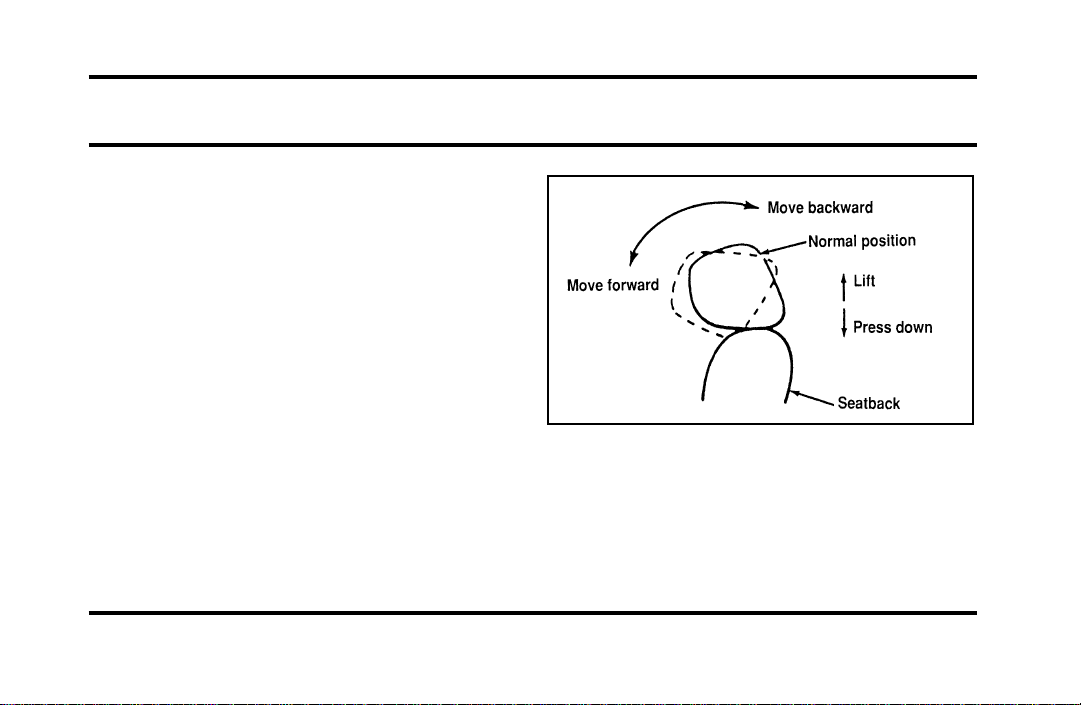
131
Seating and Safety Restraints
Seats
Head Restraints
If you use them properly, head restraints will help
protect your head and neck in a collision.
A head restraint should be placed as high as
possible behind your head without interfering with
your vision.
You can adjust the head restraints for your comfort
and protection.
Four-way head restraints
Your vehicle has the four-way head restraint. You
can adjust it in four directions. You can raise it two
(2) inches (50 mm) from its normal position, or you
can move it forward up to 60˚ until you reach the
desired position.
The four-way head restraint
File:06fnssc.ex
Update:Mon Jun 17 14:19:23 1996
132
AdjustingtheSeats
WARNING
Neveradjustthedriver’sseator
seatbackwhenthevehicleismoving.
WARNING
Alwaysdriveandridewithyour
seatbackuprightandthelapbeltsnug
andlowacrossthehips.
WARNING
Donotpilecargohigherthanthe
seatbackstoavoidinjuringpeopleina
collisionorsuddenstop.
UsingthePowerSeats
Yourvehicle’spowerseatscanbeadjustedin
severaldirections.Youcanraiseorlowerthewhole
seat,movetheseatforwardorbackwardandtilt
thefrontandbackoftheseatupordown.
Thecontrolstooperatethepowerrecliningfront
seatsarelocatedontheinsideofeachfrontdoor.
Thearrowsontheswitchesshowthedirectionof
theseatmovement.Tomovetheseatback,move
theswitchinthedesireddirection.
File:06fnssc.ex
Update:Mon Jun 17 14:19:23 1996
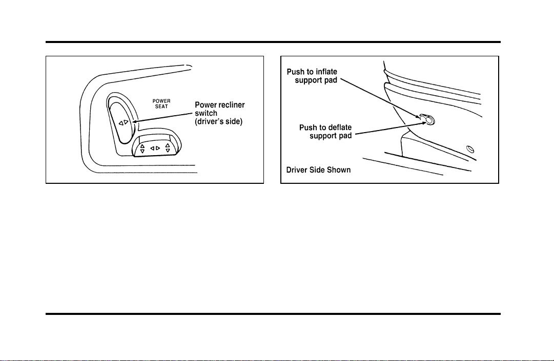
133
The power reclining seat switch on the
driver’s side
Power Lumbar Support
With this feature, you can position a lumbar
support pad in the seatback.
The seat controls for the lumbar support on
the driver’s seat
Heated Seats (If equipped)
The driver’s and front passenger’s Heated Seats are
controlled by the HEATED SEATS panel, which is
located directly below the climate control panel.
The Heated Seat System will only operate with the
ignition key in the ON position and will maintain a
temperature automatically once it is selected.
File:06fnssc.ex
Update:Mon Jun 17 14:19:23 1996
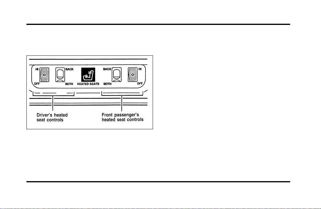
134
NOTE: Leaving the Heated Seat turned on when
you shut the vehicle off will not continue to heat
the seat.
The heated seat controls
To operate the Heated Seat System:
1. Select mode.
❑
“Both” to heat the seat back and seat cushion
❑
“Back” to heat the seat back only
2. Rotate the thumbwheel from “0” to “1” (the
lowest heat level). Allow five minutes for the
heat level to stabilize.
3. If the heat level is not high enough for
comfort, select increased heat levels “2”
through “5” (the maximum level). Allow at
least two minutes for the heat level to stabilize
at any new level selected.
4. If the heated seat switch is not turned off (“0”
on the thumbwheel), the seat will heat up to
the selected temperature level each time the
car is started.
NOTE: Cooling the seat down takes considerably
longer than increasing its heat level.
File:06fnssc.ex
Update:Mon Jun 17 14:19:23 1996
135
ImportantSafetyBeltInformation
Theuseofsafetybeltshelpstorestrainyouand
yourpassengersincaseofacollision.Inmoststates
andinCanada,thelawrequirestheiruse.
Safetybeltsprovidebestrestraintwhen:
❑
theseatbackisupright
❑
theoccupantissittingupright(notslouched)
❑
thelapbeltissnugandlowonthehips
❑
theshoulderbeltissnugagainstthechest
❑
thekneesarestraightforward
Tohelpyouremembertofastenyoursafetybelt,a
warninglightmaycomeonandachimemay
sound.SeeSafetyBeltWarningLightandChimein
theInstrumentationchapter.
Seethefollowingsectionsinthischapterfor
directionsonhowtoproperlyusethesesafetybelts.
AlsoseeSafetyRestraintsforChildreninthis
chapterforspecialinstructionsaboutusingsafety
beltsforchildren.
WARNING
Itisextremelydangeroustorideina
cargoarea,insideoroutsideofa
vehicle.Inacollision,peopleridingin
theseareasaremorelikelytobe
seriouslyinjuredorkilled.Donot
allowpeopletorideinanyareaofyour
vehiclethatisnotequippedwithseats
andsafetybelts.Besureeveryonein
yourvehicleisinaseatandusinga
safetybeltproperly.
WARNING
Alwaysdriveandridewithyour
seatbackuprightandthelapbeltsnug
andlowacrossthehips.
File:06fnssc.ex
Update:Mon Jun 17 14:19:23 1996
136
WARNING
Eachseatingpositioninyourvehicle
hasaspecificsafetybeltassembly
whichismadeupofonebuckleand
onetonguethataredesignedtobeused
asapair.1)Usetheshoulderbelton
theoutsideshoulderonly.Neverwear
theshoulderbeltunderthearm.2)
Neverswingitaroundyourneckover
theinsideshoulder.3)Neverusea
singlebeltformorethanoneperson.
WARNING
Fordrecommendsthatallsafetybelt
assembliesandattachinghardware
shouldbeinspectedbyaqualified
technicianafteranycollision.Safety
beltassembliesnotinuseduringa
collisionshouldalsobeinspectedand
replacedifeitherdamageorimproper
operationisnoted.
WARNING
Childrenshouldalwaysridewiththe
seatbackinthefullyuprightposition.
File:06fnssc.ex
Update:Mon Jun 17 14:19:23 1996
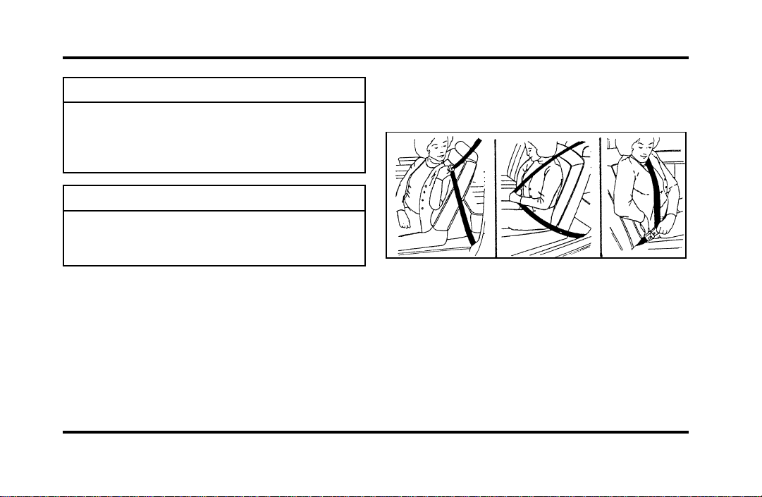
137
WARNING
Neverletapassengerholdachildon
hisorherlapwhilethevehicleis
moving.Thepassengercannotprotect
thechildfrominjuryinacollision.
WARNING
Lockthedoorsofyourvehiclebefore
drivingtolessentheriskofthedoor
comingopeninacollision.
CombinationLapandShoulder
Belts
Whileyourvehicleisinmotion,thecombination
lapandshoulderbeltadjuststoyourmovement.
However,ifyoubrakehard,cornerhardorifyour
vehiclereceivesanimpactof5mph(8km/h)or
more,thelapandshoulderbeltlocksandhelps
reduceyourforwardmovement.
Afteryougetintoyourvehicle,closethedoorand
lockit.Thenadjusttheseattothepositionthat
suitsyoubest.
Fasteningthecombinationlapandshoulder
belt
NOTE:BesuretoreadandunderstandImportant
SafetyBeltInformationinthischapter.
Toadjustthelappartofthebelt,pulluponthe
shoulderbeltuntilthelapbeltfitssnuglyandas
lowaspossiblearoundyourhips.
File:06fnssc.ex
Update:Mon Jun 17 14:19:23 1996
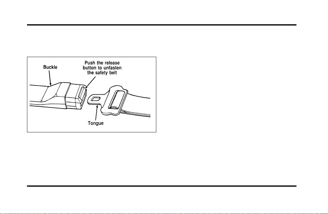
138
While the belt retracts, guide the tongue to its
original position to prevent it from striking you or
the vehicle.
Unfastening the lap/shoulder belts
Shoulder Belt Height Adjustment
Driver and right front passenger
You can adjust the shoulder belt height to one of
five (5) positions.
To adjust the belt down, push the release button
(see figures 1 and 2). To adjust the belt up, slide
the adjuster up. (You do not have to push the
release button.)
Make sure the adjuster is firmly in one of the five
positions. The belt should be adjusted up or down
until the belt rests across the middle of your
shoulder.
File:06fnssc.ex
Update:Mon Jun 17 14:19:23 1996

139
Figure 1 — The shoulder belt height adjuster Figure 2 — The shoulder belt height adjuster
File:06fnssc.ex
Update:Mon Jun 17 14:19:23 1996
140
WARNING
Positiontheshoulderbeltheight
adjustersothatthebeltrestsacrossthe
middleofyourshoulder.Besurethe
shoulderbeltisproperlypositionedon
yourshouldereachtimeyouusethe
belt.Iftheshoulderbeltisoffyour
shoulder,onyourupperarmorneck,
thereisagreaterriskofsevereinjury
inacollision.
RightFrontorRearSeatingPositions
Yourvehicleisequippedwithaduallockingmode
retractorontheshoulderbeltportionofthe
combinationlap/shouldersafetybeltforthefront
seatpassengerandrearseatpassengers.
Duallockingmoderetractorsoperateintwo
ways:
Vehiclesensitive(emergency)locking
mode
Inthisoperatingmode,theshoulderbeltretractor
willallowtheoccupantfreedomofmovement,
lockingtightonlyonhardbraking,hardcornering
orimpactsofapproximately5mph(8km/h)or
more.Theretractorcanalsobemadetolockby
pullingthebeltoutquickly.
Automaticlockingmode
Inthisoperatingmode,theshoulderbeltretractor
willbeautomaticallylockedandwillremainlocked
whenthecombinationlap/shouldersafetybeltis
buckled,anddoesnotallowtheoccupantfreedom
ofmovement.Thismodeprovidesthefollowing:
❑
Atightlap/shoulderbeltontheoccupant.
❑
Childseatinstallationrestraint.
File:06fnssc.ex
Update:Mon Jun 17 14:19:23 1996
141
WARNING
Rear-facingchildseatsorinfantcarriers
shouldneverbeplacedinthefront
seats.
Thismodemustbeusedwheninstallingachild
seatonthefrontpassengerseatandrearseats
whereduallockingretractorsareprovided.To
switchtheretractorfromtheemergencylocking
modetotheautomaticlockingmode,performthe
followingsteps:
1. Bucklethelap/shouldercombinationbelt.
2. Grasptheshoulderportionofthebeltandpull
downwarduntilallofthebeltisextractedand
aclickisheard.Atthistime,theretractorisin
theautomaticlockingmode(childrestraint
mode).
3. Aclickingsoundwillcontinuetobeheardas
thebeltisallowedtoretract.
NOTE:Whenthecombinationlap/shoulderbeltis
unbuckledandallowedtoretractcompletely,the
retractorwillswitchtothevehiclesensitive
(emergency)lockingmode.Seethedetailed
instructionsunderSafetySeatsforChildrenin
thischapter.
LapBelts
Thelapbeltinthecenterofthefrontseatdoesnot
adjustautomatically.Youmustadjustittofitsnugly
andaslowaspossiblearoundyourhips.Donot
wearitaroundyourwaist.
File:06fnssc.ex
Update:Mon Jun 17 14:19:23 1996
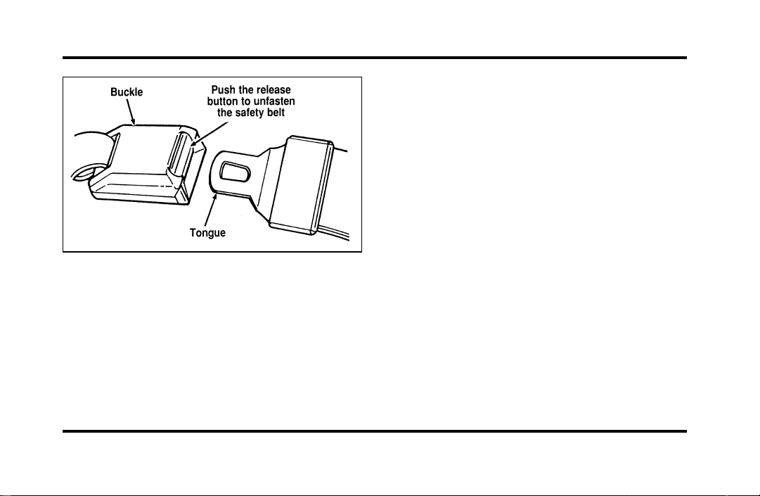
142
Unfastening the lap belts in the center front
seating position
NOTE: Be sure to read and understand Important
Safety Belt Information in this chapter.
Pull the belt across your hips and insert the
tongue into the correct buckle on your seat until
you hear a snap and feel it lock. Make sure the
buckle is securely fastened.
If you need to lengthen the belt, unfasten it and tip
the belt tongue at a right angle to the belt. Pull the
belt tongue over your lap until it reaches the
buckle.
If you need to shorten the belt, pull on the loose
end of the webbing until the belt fits snugly.
To unfasten the belt, push the release button on
the buckle. This allows the tongue to unlatch from
the buckle.
Safety Belt Extension Assembly
For some people, the safety belt may be too short
even when it is fully extended. You can add about
eight inches (20 cm) to the belt length with a
safety belt extension assembly (part number
611C22). Safety belt extensions are available at no
cost from your dealer.
Use only extensions manufactured by the same
supplier as the safety belt. Manufacturer
identification is located at the end of the webbing
File:06fnssc.ex
Update:Mon Jun 17 14:19:23 1996
143
onthelabel.Also,usethesafetybeltextensiononly
ifthesafetybeltistooshortforyouwhenfully
extended.Donotuseextensiontochangethefitof
theshoulderbeltacrossthetorso.
WARNING
Failuretofollowtheseinstructionswill
affecttheperformanceofthesafety
beltsandincreasetheriskofpersonal
injury.
SafetyBeltMaintenance
Checkthesafetybeltsystemsperiodicallytomake
surethattheyworkproperlyandarenotdamaged.
Allsafetybeltassemblies,includingretractors,
buckles,frontseatbeltbucklesupportassemblies
(slidebar)(ifequipped),shoulderbeltheight
adjusters(ifequipped),childsafetyseattether
bracketassemblies(ifequipped),andattaching
hardware,shouldbeinspectedafteranycollision.
Fordrecommendsthatallsafetybeltassemblies
usedinvehiclesinvolvedinacollisionbereplaced.
However,ifthecollisionwasminorandaqualified
technicianfindsthatthebeltsdonotshowdamage
andcontinuetooperateproperly,theydonotneed
tobereplaced.Safetybeltassembliesnotinuse
duringacollisionshouldalsobeinspectedand
replacedifeitherdamageorimproperoperationis
noted.
AirBagSupplementalRestraint
System(SRS)
ImportantAirBagPrecautions
Yourvehicleisequippedwithasupplemental
restraintsystemdesignedtoworkwiththesafety
beltstohelpprotectyouandyourrightfrontseat
passengerintheeventofacollision.TheAirBag
SupplementalRestraintSystemisprimarilydesigned
toreducecertainupperbodyinjuries.
File:06fnssc.ex
Update:Mon Jun 17 14:19:23 1996
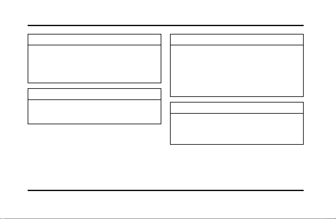
144
WARNING
Alloccupantsofthevehicle,including
thedriver,shouldalwaysweartheir
safetybelts,failuretodosomay
increasetheriskofpersonalinjuryin
theeventofacollision.
WARNING
Therightfrontpassengerairbagisnot
designedtorestrainoccupantsinthe
centerfrontseatingposition.
WARNING
Donotplaceobjectsormount
equipmentonorneartheairbagcovers
thatmaycomeintocontactwithan
inflatingairbag.Failuretofollowthese
instructionsmayincreasetheriskof
personalinjuryintheeventofa
collision.
WARNING
Donotattempttoservice,repair,or
modifytheairbagSupplemental
RestraintSystemoritsfuses.Seeyour
FordorLincoln-Mercurydealer.
File:06fnssc.ex
Update:Mon Jun 17 14:19:23 1996
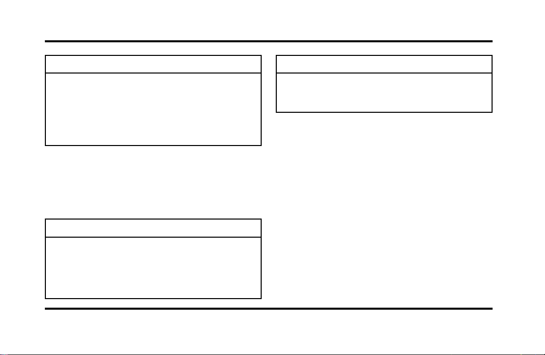
145
WARNING
Ifyouareclosetoaninflatingairbag,
itcouldseriouslyinjureyou.Position
yourseatsuchthatitisasfarback
fromthesteeringwheelaspossiblebut
stillallowsyoutoproperlycontrolthe
vehicle.
ChildrenandAirBags
NOTE:Foradditionalimportantsafetyinformation
ontheproperuseofseatbelts,childseats,and
infantseats,pleasereadtheentireSafetyRestraints
chapterinthisownerguide.
WARNING
Childrenshouldalwaysweartheir
safetybelts.Failuretofollowthese
instructionsmayincreasetheriskof
personalinjuryintheeventofa
collision.
WARNING
Rear-facingchildseatsandinfant
carriersshouldneverbeplacedinthe
frontseats.
HowDoestheAirBagSupplemental
RestraintSystemWork?
TheAirBagSupplementalRestraintSystemis
designedtoactivatewhenthevehicleisina
collisionsimilartohittingafixedbarrierheadonat
8-14mph(13-23km/h).Thefactthattheairbags
didnotinflateinacollisiondoesnotmeanthat
somethingiswrongwiththesystem.Rather,it
meanstheforceswerenotofthetypesufficientto
causeactivation.
Ifthevehicleisinamoderateorseverefrontal
collision,thesystemisactivatedandtheairbags
inflaterapidly.Aftertheairbaginflates,itwill
quicklydeflate.Aftertheairbagdeployment,you
maynoticeasmoke-like,powderyresidueorsmell
File:06fnssc.ex
Update:Mon Jun 17 14:19:23 1996
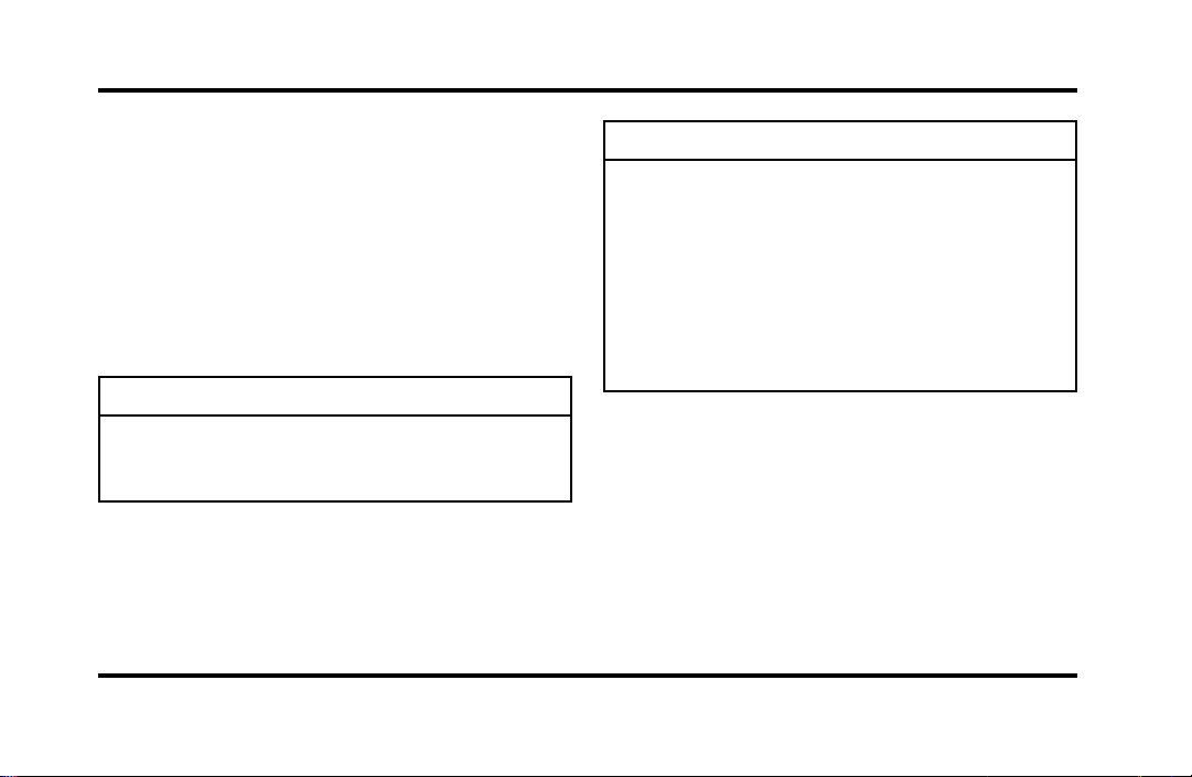
146
theburntpropellant.Thisisnormal.Theresidue
mayconsistofcornstarchortalcumpowder(which
isusedtolubricatetheairbag)orsodium
compounds,suchassodiumcarbonates(e.g.baking
soda)thatresultfromthecombustionprocessthat
inflatestheairbag.Smallamountsofsodium
hydroxidemaybepresentwhichmayirritatethe
skinandeyes,butnoneoftheresidueistoxic.The
AirBagSupplementalRestraintSystemwillreduce,
butnoteliminateallinjuriesinanaccident.
WARNING
Severalairbagsystemcomponentsget
hotafterinflation.Donottrytotouch
themafterinflation.
WARNING
Theairbagwillinflateonlyonce.The
systemisdesignedtofunctionona
one-time-onlybasis.Iftheairbagis
inflated,THEAIRBAGWILLNOT
FUNCTIONAGAINANDMUSTBE
REPLACEDIMMEDIATELY.Iftheair
bagisnotreplaced,thiswillincrease
theriskofinjuryinasubsequent
collision.
TheAirBagSupplementalRestraintSystemconsists
of:
❑
driverandpassengerairbagmodules(which
includetheinflatorsandairbags),
❑
oneormoreimpactandsafingsensors,
❑
asystemdiagnosticmodule,
File:06fnssc.ex
Update:Mon Jun 17 14:19:23 1996

147
❑
a readiness light and tone,
❑
and the electrical wiring which connects the
components.
The diagnostic module monitors its own circuits,
the air bag electrical system, the air bag readiness
light, the air bag power, and the air bag inflators.
Determining if System Is Operational
The Air Bag Supplemental Restraint System uses a
readiness light and a tone to indicate the condition
of the system. The readiness light is in the
instrument cluster. When you turn the ignition key
to ON, this light will illuminate for approximately
six (6) seconds and then turn off. This indicates
that the system is operating normally. NOTE:
Routine maintenance of the air bag system is not
required.
A problem with the system is indicated by one or
more of the following:
❑
the readiness light will either flash or stay lit,
❑
the readiness light will not light immediately
after ignition is turned on,
❑
a group of five beeps will be heard. The tone
pattern will repeat periodically until the problem
and light are repaired.
If any of these things happen, even intermittently,
have the Air Bag Supplemental Restraint System
serviced at your Ford or Lincoln-Mercury dealer
immediately. Unless serviced, the system may not
function properly in the event of a collision.
Disposal of Air Bags and Air Bag
Equipped Vehicles
For disposal of air bags or air bag equipped vehicles,
see your local Ford or Lincoln-Mercury dealer. Air
bags MUST BE disposed of by qualified personnel.
File:06fnssc.ex
Update:Mon Jun 17 14:19:23 1996
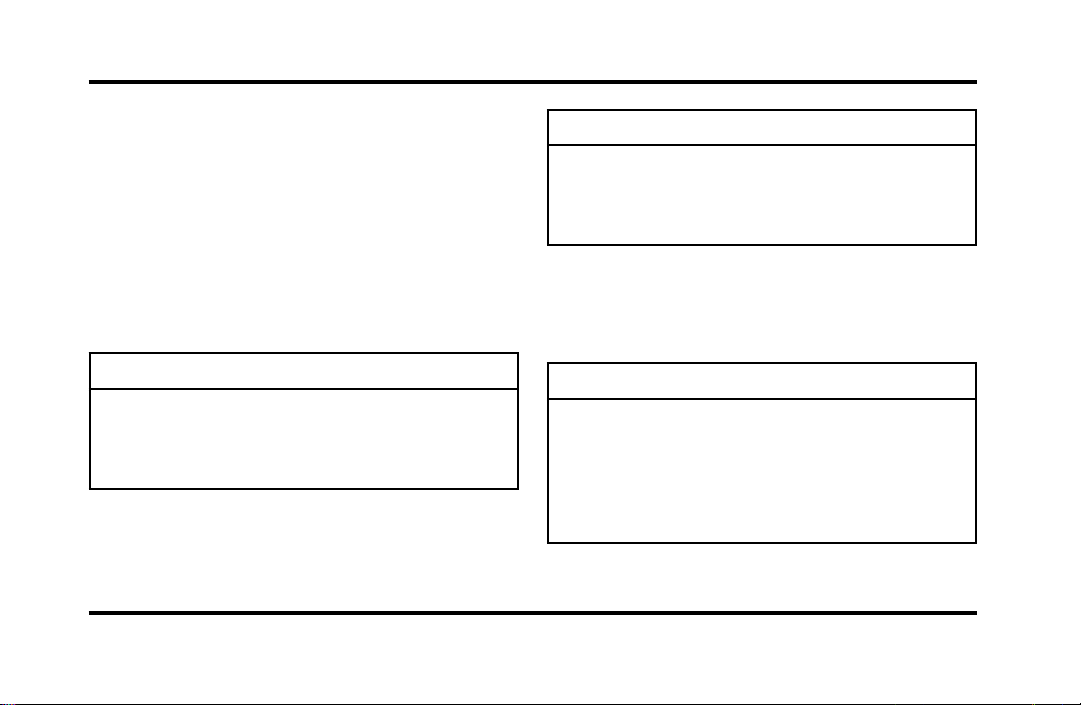
148
SafetyRestraintsforChildren
IntheU.S.andCanada,youarerequiredbylawto
usesafetyrestraintsforchildren.Ifsmallchildren
rideinyourvehicle—thisgenerallyincludes
childrenwhoarefouryearsoldoryoungerand
whoweigh40pounds(18kg)orless—youmust
puttheminsafetyseatsthataremadespeciallyfor
children.Safetybeltsalonedonotprovide
maximumprotectionforthesechildren.Checkyour
localandstatelawsforspecificrequirements.
WARNING
Neverletapassengerholdachildon
hisorherlapwhilethevehicleis
moving.Thepassengercannotprotect
thechildfrominjuryinacollision.
WARNING
Cargoshouldalwaysbesecuredto
preventitfromshiftingandcausing
damagetothevehicleorharmto
passengers.
Whenpossible,putchildrenintherearseatofyour
vehicle.Accidentstatisticssuggestthatchildrenare
saferwhenproperlyrestrainedintherearseating
positionsthaninthefrontseatingpositions.
WARNING
Carefullyfollowallofthe
manufacturer’sinstructionsincluded
withthesafetyseatyouputinyour
vehicle.Ifyoudonotinstallanduse
thesafetyseatproperly,thechildmay
beinjuredinasuddenstoporcollision.
File:06fnssc.ex
Update:Mon Jun 17 14:19:23 1996
149
WARNING
Safetybeltsandseatscanbecomehot
inavehiclethathasbeenclosedupin
sunnyweather;theycouldburnasmall
child.Checkseatcoversandbuckles
beforeyouplaceachildanywherenear
them.
WARNING
Donotleavechildren,unreliableadults,
orpetsunattendedinyourvehicle.
SafetySeatsforChildren
Useasafetyseatthatisrecommendedforthesize
andweightofthechild.Alwaysfollowthesafety
seatmanufacturer’sinstructionswheninstallingand
usingthesafetyseat.
Fordrecommendstheuseofachildsafetyseat
havingatoptetherstrap.Installthechildsafety
seatinaseatingpositionwhichiscapableof
providingatetheranchorage.Formoreinformation
ontoptetherstrapsseeAttachingSafetySeatsWith
TetherStrapsinthischapter.
Wheninstallingachildsafetyseat,besuretouse
thecorrectsafetybeltbuckleforthatseating
position,andmakesurethetongueissecurely
fastenedinthebuckle.Forashoulder/lapbelt
combinationwithaslidingtongue,makesurethe
retractorisintheautomaticlockingmode.
WARNING
Rear-facingchildseatsorinfantcarriers
shouldneverbeplacedinthefront
seats.
File:06fnssc.ex
Update:Mon Jun 17 14:19:23 1996
150
WARNING
Whenusingforward-facingchildseats
movethepassengerseatasfarback
fromtheinstrumentpanelaspossible.
Neversecurerear-facingchildseatsor
infantcarriersinthefrontseat.
Allchildrestraintsystemsaredesignedtobe
securedinvehicleseatsbylapbeltsorbythelap
portionofalap-shoulderbelt.
WARNING
Ifyoudonotproperlysecurethesafety
seat,thechildoccupyingtheseatmay
beinjuredduringacollisionorsudden
stop.Anunsecuredsafetyseatcould
alsoinjureotherpassengers.
WARNING
Carefullyfollowallofthe
manufacturer’sinstructionsincluded
withthesafetyseatyouputinyour
vehicle.Ifyoudonotinstallanduse
thesafetyseatproperly,thechildmay
beinjuredinasuddenstoporcollision.
WARNING
Alwayskeepthebucklereleasebutton
pointingupwardandawayfromthe
childseat,withthetonguebetweenthe
childseatandthereleasebuttonas
showninthefollowingillustration.
File:06fnssc.ex
Update:Mon Jun 17 14:19:23 1996
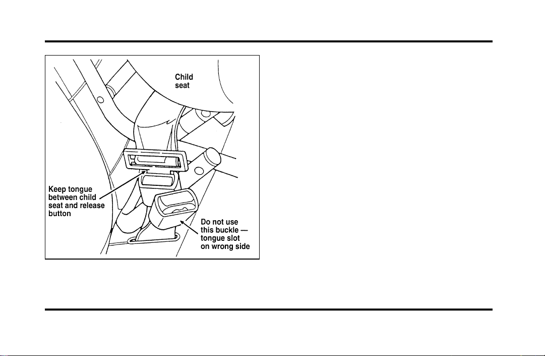
151
Safety belt buckle placement for child seats
Installing Safety Seats in the Front
and Rear Seating Positions
Your vehicle is equipped with a dual locking mode
retractor on the shoulder belt portion of the
combination lap/shoulder safety belt for the front
seat passenger and rear passengers.
If you choose to install a child safety seat in the
front seating position, move vehicle seat as far back
as possible.
For seating positions equipped with a dual-locking
mode retractor, use the following procedure:
1. Position the child seat in center of passenger
seating position.
File:06fnssc.ex
Update:Mon Jun 17 14:19:23 1996
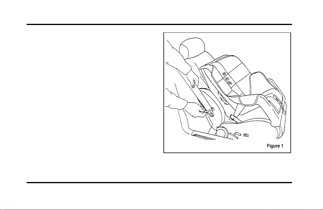
152
2. Pull down on shoulder belt, then grasp
shoulder belt and lap belt together. See Figure
1.
File:06fnssc.ex
Update:Mon Jun 17 14:19:23 1996
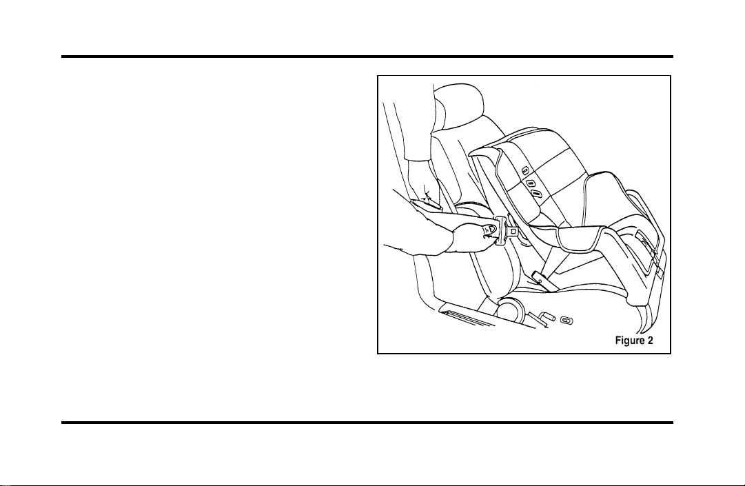
153
3. While holding the shoulder and lap belt
portions together, route the tongue through the
child seat according to the child seat
manufacturer’s instructions. See Figure 2. Be
sure that the belt webbing is not twisted.
Routing the lap/shoulder belt
File:06fnssc.ex
Update:Mon Jun 17 14:19:23 1996
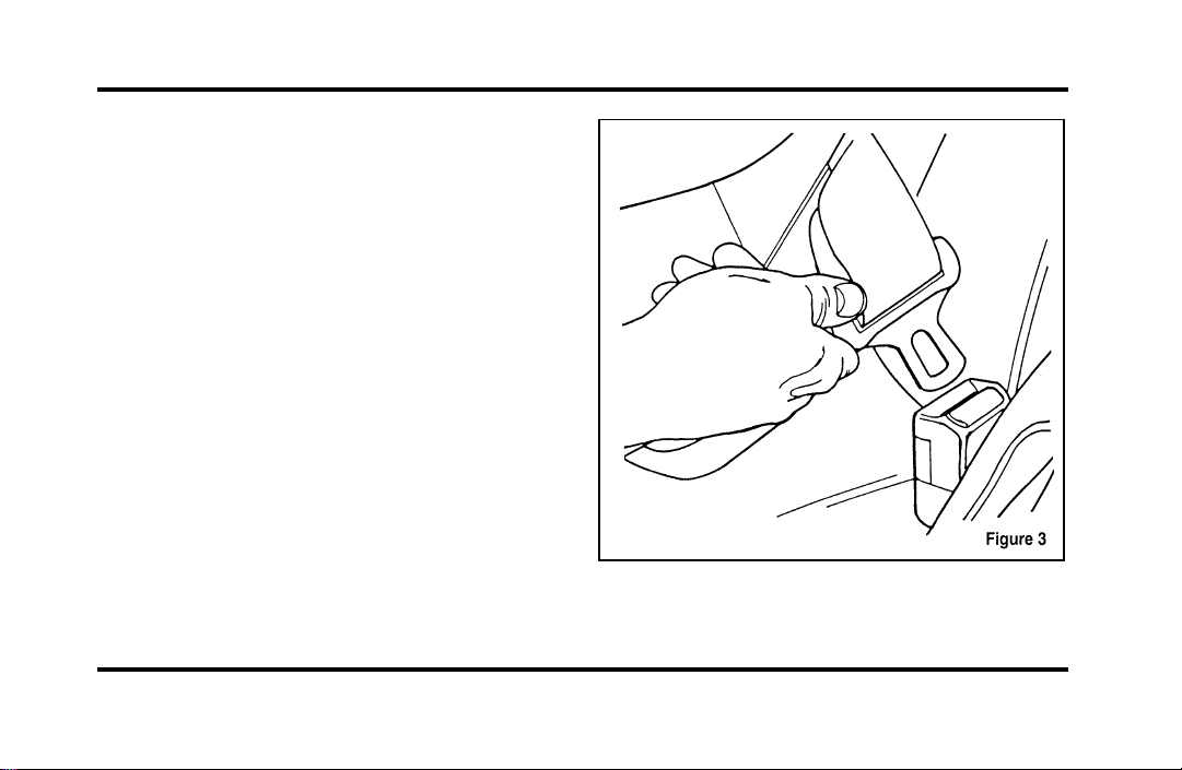
154
4. Insert the belt tongue into the proper buckle
for that seating position until you hear and feel
the latch engage. See Figure 3. Make sure
tongue is latched securely to buckle by pulling
on tongue.
Buckling the belt.
File:06fnssc.ex
Update:Mon Jun 17 14:19:23 1996
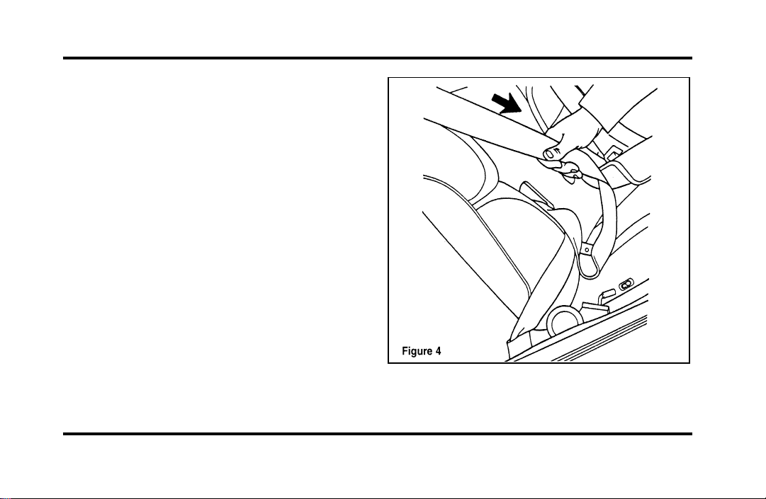
155
5. Grasp the shoulder portion of the belt and pull
downward until all of the belt is extracted and
a click is heard. At this time, the retractor is in
the automatic locking mode (child restraint
mode). See Figure 4.
NOTE: The dual locking mode retractor must be in
the automatic locking mode to properly restrain a
child seat.
Setting the retractor to automatic locking
mode
File:06fnssc.ex
Update:Mon Jun 17 14:19:23 1996
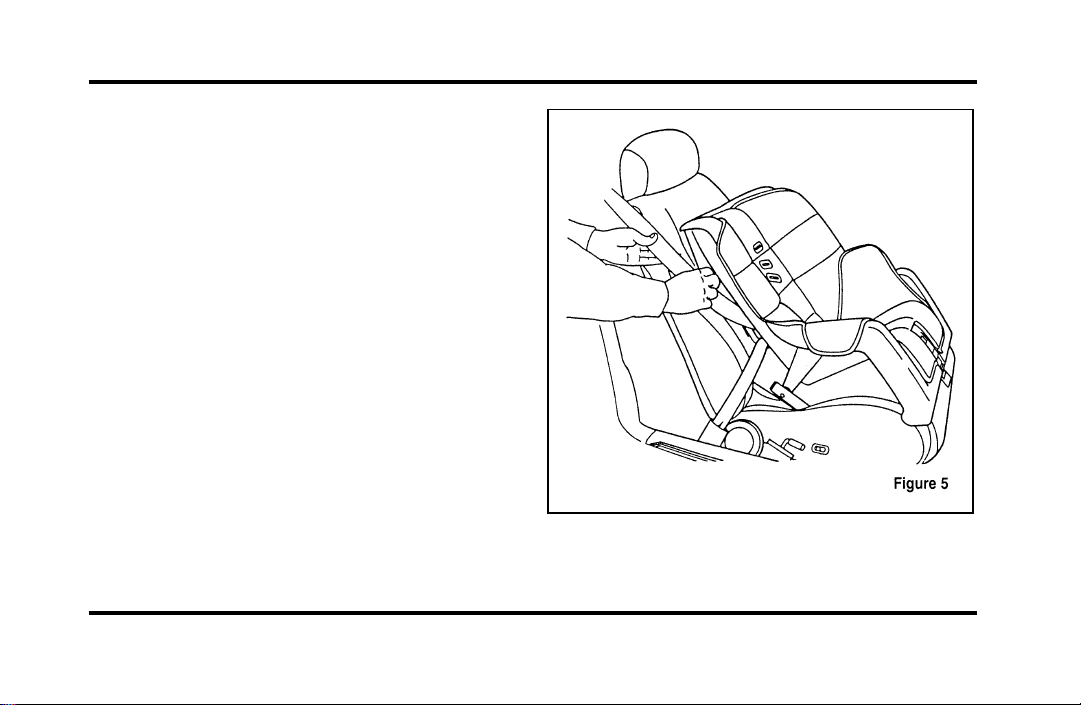
156
6. Allow the belt to retract. A clicking sound will
be heard as the belt retracts. This indicates the
retractor is in the automatic locking mode. Pull
on the lap belt portion across the child seat
towards the buckle and continue to pull up on
the shoulder belt portion while pushing down
on the child seat allowing the shoulder belt to
retract to remove any slack in the seat belt. See
Figures 5 and 6.
File:06fnssc.ex
Update:Mon Jun 17 14:19:23 1996
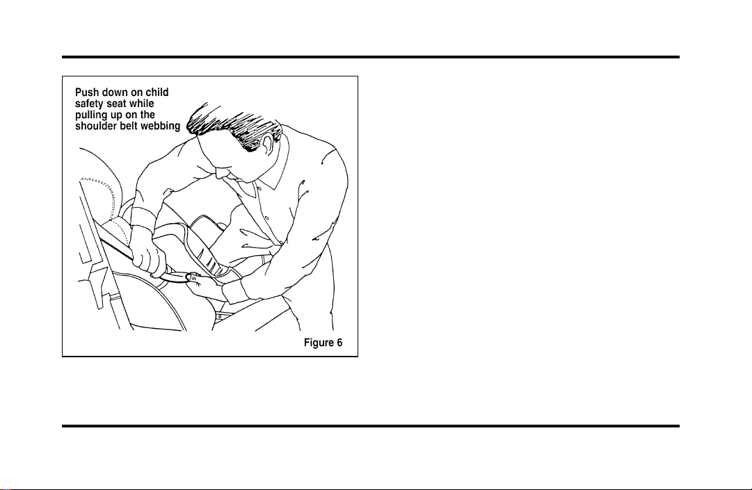
157
7. Before placing the child in the child seat,
forcibly tilt the seat from side to side and in
forward directions to make sure that the seat is
securely held in place. See Figure 7.
File:06fnssc.ex
Update:Mon Jun 17 14:19:23 1996
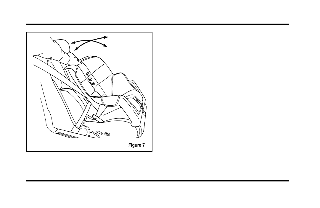
158
Checking that the seat is secure
8. Double check that the retractor is in the
automatic locking mode. Try to pull more belt
out of the retractor. If you cannot, the belt is
in the automatic locking mode. See Figure 8.
File:06fnssc.ex
Update:Mon Jun 17 14:19:23 1996
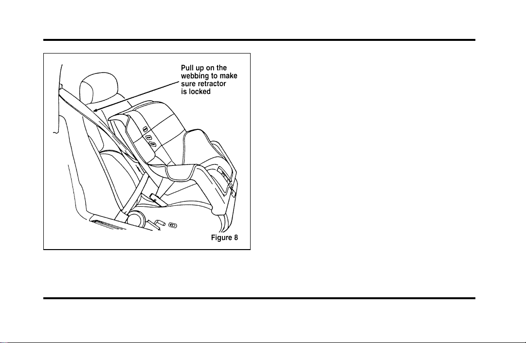
159
Checking the retractor
9. Check to make sure that the child seat is
properly secured prior to each use. If the
retractor is not locked, repeat steps 6 through
8.
NOTE: To remove the retractor from automatic
lock mode, allow seat belt to retract fully to its
stowed position and the retractor will automatically
switch back to the vehicle sensitive locking mode
for normal adult usage.
Installing a Child Safety Seat at the
Front Center Seating Position with
Adjustable Lap Belt
1. Lengthen the lap belt. To lengthen the belt,
hold the tongue so that its bottom is
perpendicular to the direction of webbing while
sliding the tongue up the webbing.
2. Place the child safety seat in the center seating
position.
File:06fnssc.ex
Update:Mon Jun 17 14:19:23 1996
160
3. Routethetongueandwebbingthroughthe
childseataccordingtothechildseat
manufacturer’sinstructions.
4. Insertthebelttongueintotheproperbuckle
forthecenterseatingpositionuntilyouheara
snapandfeelitlatch.Makesurethetongueis
securelyfastenedtothebucklebypullingon
tongue.
5. Pushdownonthechildseatwhilepullingon
thelooseendofthelapbeltwebbingtotighten
thebelt.
6. Beforeplacingthechildintothechildseat,
forciblytiltthechildseatfromside-to-sideand
inforwarddirectionstoensurethattheseatis
heldsecurelyinplace.Ifthechildseatmoves
excessively,repeatsteps5through6,or
properlyinstallthechildseatinadifferent
seatingposition.
WARNING
Carefullyfollowallofthe
manufacturer’sinstructionsincluded
withthesafetyseatyouputinyour
vehicle.Ifyoudonotinstallanduse
thesafetyseatproperly,thechildmay
beinjuredinasuddenstoporcollision.
AttachingSafetySeatsWithTether
Straps
Somemanufacturersmakesafetyseatsthatinclude
atetherstrapthatgoesoverthebackofthevehicle
seatandattachestoananchoringpoint.Other
manufacturersofferthetetherstrapasanaccessory.
Contactthemanufacturerofyourchildsafetyseat
forinformationaboutorderingatetherstrap.
File:06fnssc.ex
Update:Mon Jun 17 14:19:23 1996
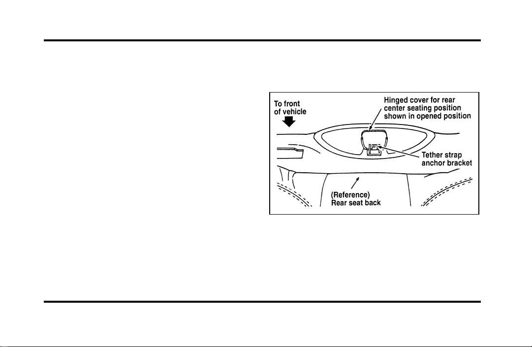
161
Tether anchorage hardware
All vehicles include a tether anchor installed at the
rear center seating position for use with child safety
seats. Attachment holes (at each rear outboard
seating position) have been provided in your vehicle
to attach anchor hardware, if required. Additional
kits can be obtained and installed at no charge from
any Ford or Lincoln-Mercury dealer.
Tether strap anchorage locations (rear
center seating position only)
Refer to Figures 1 and 2.
The tether strap anchorage bracket for the rear
center seating position was factory installed and is
located directly beneath the rear window trim
panel, which is behind the rear seat back. To use
this anchorage, do the following:
1. Open the hinged cover located at the front of
the high mount stop light. This cover conceals
the tether strap anchor bracket, as shown in
Figures 1 and 2.
NOTE: Do not raise the hinged cover of the trim
panel beyond its limit, to prevent damage to the
hinge.
Figure 1
File:06fnssc.ex
Update:Mon Jun 17 14:19:23 1996
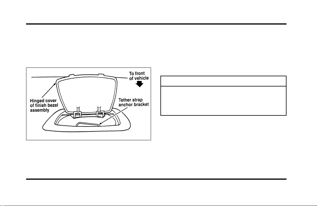
162
2. Installthetetherstrapbracketlocateddirectly
belowthecover.RefertoFigure2.Ifthe
centerseatingpositionisnotbeingused,the
covershouldbekeptclosedforaneat
appearance.
Figure2
SafetyBeltsforChildren
Childrenwhoaretoolargeforchildsafetyseats
shouldalwayswearsafetybelts.(Seeinstructions
withyourchildseat,orcontactitsmanufacturer,to
determinemaximumsizeofchildthatwillsafelyfit
intheseat.)
WARNING
Ifsafetybeltsarenotproperlyworn
andadjustedasdescribed,theriskof
seriousinjurytothechildinacollision
willbemuchgreater.
Iftheshoulderbeltportionofthelap/shoulderbelt
canbepositionedsothatitdoesnotcrossorrest
infrontofthechild’sfaceorneck,thechildshould
wearthelap/shoulderbelt.Movingthechildcloser
totheseatbeltbucklemayhelpprovideagood
shoulderbeltfit.
File:06fnssc.ex
Update:Mon Jun 17 14:19:23 1996
163
Toimprovethefitoflapandshoulderbeltson
childrenwhohaveoutgrownchildsafetyseats,Ford
recommendsuseofabelt-positioningboosterseat
thatislabelledasconformingtoallFederalmotor
vehiclesafetystandards.Belt-positioningbooster
seatsraisethechildandprovideashorter,firmer
seatingcushionthatencouragessaferseatingposture
andbetterfitoflapandshoulderbeltsonthechild.
Abelt-positioningboostershouldbeusedifthe
shoulderbeltrestsinfrontofthechild’sfaceor
neck,orifthelapbeltdoesnotfitsnuglyonboth
thighs,orifthethighsaretooshorttoletthechild
sitallthewaybackontheseatcushionwhenthe
lowerlegshangovertheedgeoftheseatcushion.
Youmaywishtodiscussthespecificneedsofyour
childwithyourpediatrician.
WARNING
Donotuseabelt-positioningbooster
withalap-onlybelt.
Lapbeltsandthelapbeltportionoflapand
shoulderbeltsshouldalwaysbewornsnuglyand
belowthehips,touchingthechild’sthighs.
WARNING
Childrenshouldalwaysridewiththe
seatbackinthefullyuprightposition.
File:06fnssc.ex
Update:Mon Jun 17 14:19:23 1996
165
Starting
Fuel-InjectedEngines
Whenstartingafuel-injectedengine,themost
importantthingtorememberistoavoid
pressingdownontheacceleratorbeforeor
duringstarting.Onlyusetheacceleratorwhenyou
haveproblemsgettingyourvehiclestarted.See
StartingYourEngineinthischapterfordetails
aboutwhentousetheacceleratorwhileyoustart
yourvehicle.
StartingYourVehicle
PreparingtoStartYourVehicle
WARNING
Donotstartyourvehicleinaclosed
garageorinotherenclosedareas.
Exhaustfumescanbetoxic.Always
openthegaragedoorbeforeyoustart
theengine.
Beforeyoustartyourvehicle,dothefollowing:
1. Makesurealloccupantsinthevehiclebuckle
theirsafetybelts.SeeSafetyRestraintsinthe
Indexformoredetails.
2. Makesuretheheadlampsandotheraccessories
areturnedoffwhenstarting.
File:08fntoc.ex
Update:Mon Jun 17 14:19:30 1996

166
3. Make sure that the gearshift is in P (Park) and
the parking brake is set before you turn the
key.
Before you start your vehicle, you should test the
warning lights on the instrument panel to make
sure that they work. Refer to the Instrumentation
chapter.
Starting Your Engine
To start your engine:
1. Follow the steps under Preparing to Start Your
Vehicle at the beginning of this section.
2. Turn the ignition key to the ON position.
3. DO NOT depress the accelerator pedal when
starting your engine. DO NOT use the
accelerator while the vehicle is parked.
4. Turn the key to the START position (cranking)
until the engine starts. Allow the key to return
to the ON position after the engine has started.
If you have difficulty in turning the key, rotate
the steering wheel slightly because it may be
binding.
For a cold engine:
❑
At temperatures 10˚F (-12˚C) and below: If
the engine does not start in fifteen (15)
seconds on the first try, turn the key to OFF,
wait approximately ten (10) seconds so you do
not flood the engine, then try again.
❑
At temperatures above 10˚F (-12˚C): If the
engine does not start in five (5) seconds on
the first try, turn the key to OFF, wait
approximately ten (10) seconds so you do not
flood the engine, then try again.
File:08fntoc.ex
Update:Mon Jun 17 14:19:30 1996

167
For a warm engine:
❑
Do not hold the key in the START position for
more than five (5) seconds at a time. If the
engine does not start within five (5) seconds on
the first try, turn the key to the OFF position.
Wait a few seconds after the starter stops, then
try again.
Whenever you start your vehicle, release the key
as soon as the engine starts. Excessive cranking
could damage the starter.
After you start the engine, let it idle for a few
seconds. Keep your foot on the brake pedal and
put the gearshift lever in gear. Release the parking
brake. Slowly release the brake pedal and drive
away in the normal manner.
NOTE: Your vehicle has an interlock that
prevents you from shifting out of P (Park) unless
your foot is on the brake pedal.
If the engine does not start after two attempts:
1. Turn the ignition key to the OFF position.
2. Press the accelerator all the way to the floor
and hold it.
3. Turn the ignition key to the START position.
4. Release the ignition key when the engine starts.
5. Release the accelerator gradually as the engine
speeds up.
If the engine still does not start, the fuel pump
shut-off switch may have been activated. For
directions on how to reset the switch see Fuel
Pump Shut-Off Switch in the index.
File:08fntoc.ex
Update:Mon Jun 17 14:19:30 1996
168
Acomputersystemcontrolstheengine’sidle
speed.Whenyoustartyourvehicle,the
engine’sidlespeednormallyrunshigherthan
whenitiswarmedup.Thesefasterengine
speedswillmakeyourvehiclemoveslightly
fasterthanitsnormalidlespeed.Itshould,
however,slowdownafterashorttime.Ifit
doesnot,havetheidlespeedchecked.
Iftheengineidlespeeddoesnotslowdown
automatically,donotallowyourvehicletoidle
formorethan10minutes.Havethevehicle
checked.
WARNING
Extendedidlingathighenginespeeds
canproduceveryhightemperaturesin
theengineandexhaustsystem,creating
theriskoffireorotherdamage.
WARNING
Donotpark,idle,ordriveyourvehicle
indrygrassorotherdrygroundcover.
Theemissionsystemheatsupthe
enginecompartmentandexhaust
system,whichcanstartafire.
EngineBlockHeater(Ifequipped)
Engineblockheatersarestronglyrecommendedif
youliveinaregionwheretemperaturesreach-10˚F
(-23˚C)orbelow.Anengineblockheaterwarms
theenginecoolant,whichimprovesstarting,warms
uptheenginefaster,andallowstheheater-defrost
systemtorespondquickly.
Toturntheheateron,simplyplugitintoa
grounded110-voltoutlet.Fordrecommendsthat
youusea110-voltcircuitthatisprotectedbya
groundfaultcircuitinterrupter.
File:08fntoc.ex
Update:Mon Jun 17 14:19:30 1996
169
WARNING
Topreventelectricalshock,donotuse
yourheaterwithungroundedelectrical
systemsortwo-pronged(cheater)
adapters.
Forbestresults,plugtheheaterinatleastthree
hoursbeforeyoustartyourvehicle.Usingthe
heaterforlongerthanthreehourswillnotdamage
theengine,soyoucanplugitinatnighttostart
yourvehiclethefollowingmorning.
Pushing
Vehicleswithautomatictransaxlescannotbestarted
bypushing.FollowthedirectionsunderIfYour
VehicleNeedsaJump-StartintheRoadside
EmergenciesChapter.
Carbonmonoxide,althoughcolorlessandodorless,
ispresentinexhaustfumes.Takeprecautionsto
avoiditsdangerouseffects.
WARNING
Donotstartyourvehicleinaclosed
garageorinotherenclosedareas.
Exhaustfumescanbetoxic.Always
openthegaragedoorbeforeyoustart
theengine.
File:08fntoc.ex
Update:Mon Jun 17 14:19:30 1996
170
WARNING
Ifyousmellexhaustfumesinsideyour
vehicle,haveyourdealerinspectyour
vehicleimmediately.Donotdriveif
yousmellexhaustfumes.
Havetheexhaustandbodyventilationsystems
checkedwhenever:
❑
yourvehicleisraisedforservice
❑
thesoundoftheexhaustsystemchanges
❑
yourvehiclehasbeendamagedinacollision
Improveyourventilationbykeepingallairinlet
ventsclearofsnow,leaves,andotherdebris.
Iftheengineisidlingwhileyouarestoppedinan
openareaforlongperiodsoftime,openthe
windowsatleastoneinch(2.5cm).Also,adjust
theheatingorairconditioningsystemtobringin
outsideair.
IfyouusetheElectronicAutomaticClimate
Control,setthefanspeedselectordialtoamedium
orhighblowerspeedwiththeVENTorPNL-FLR
functionbuttonspressed.
File:08fntoc.ex
Update:Mon Jun 17 14:19:30 1996

171
Driving
Brakes
Applying the Brakes
Your vehicle has anti-lock disc brakes on all four
wheels. They adjust automatically as the brake pads
wear down.
When you press down hard on the brake pedal, the
wheels will not lock and slide. The Anti-lock Brake
System (ABS) automatically starts releasing and
reapplying the front brakes independently and the
rear brakes together whenever your wheels start to
lock. When this happens, you will feel the brake
pedal pulsate. This is an indication that the ABS is
working correctly and is normal.
Each time you turn the ignition key to the ON
position, the anti-lock brake system will function
through one test cycle. When this happens, the
ANTI-LOCK light will come on for up to five
seconds and a clunk may be felt in the pedal. If the
light stays on longer than five seconds, shut off the
engine and restart. If it remains on, it means the
anti-lock brake system is disabled and should be
serviced immediately to restore the benefits of the
anti-lock feature. Normal braking is not affected
unless the brake warning light is also lit.
The Anti-lock Brake System has self-check
capabilities. As described above, the system turns on
the ANTI-LOCK light each time you start your
engine. After the engine is started and the
ANTI-LOCK light turns off, the system performs
another test the first time the vehicle reaches 14
m.p.h. (22 km/h). The system turns on the ABS
pump motor for approximately 1/2 second. At this
time, a mechanical noise may be heard. This is a
normal part of the self-check feature. If a
malfunction is found during this check the
ANTI-LOCK light will come on.
File:09fngfc.ex
Update:Fri Sep 6 08:48:49 1996

172
Do not drive with your foot resting on the brake
pedal; you will wear out the linings and increase
your vehicle’s stopping distance. Brake rotor damage
may also eventually occur.
NOTE: If you are driving down a long or steep hill,
shift to a lower gear and do not apply your brakes
continuously. If you apply your brakes continuously,
they may overheat and become less effective.
Occasional brake squeal during light to moderate
stops does not affect the function of the brake
system and is normal. However, if the squeal
becomes louder or more frequent, have your brakes
inspected by your dealer or a qualified service
technician.
Ford Motor Company has not found any
detrimental effects of popular mobile radio
transmitting equipment installed on vehicles with
the anti-lock brake system, if the equipment is
installed according to the manufacturer’s
instructions. However, if mobile radio transmitting
equipment is installed in your vehicle and, if either
the anti-lock brake system cycles or the ANTI-LOCK
light comes on at any time other than right after
you turn the key to the ON position or during a
sudden stop, have your mobile radio dealer inspect
the installation.
Parking Brake
The parking brake should be used whenever
you park your vehicle.
The parking brake is suspended just below the
lower left corner of the instrument panel.
To set the parking brake:
1. Move the gearshifter to P (Park).
2. Push the parking brake pedal down firmly and
fully with your left foot.
The Brake System Light in the warning lights will
glow once the parking brake is set.
File:09fngfc.ex
Update:Fri Sep 6 08:48:49 1996
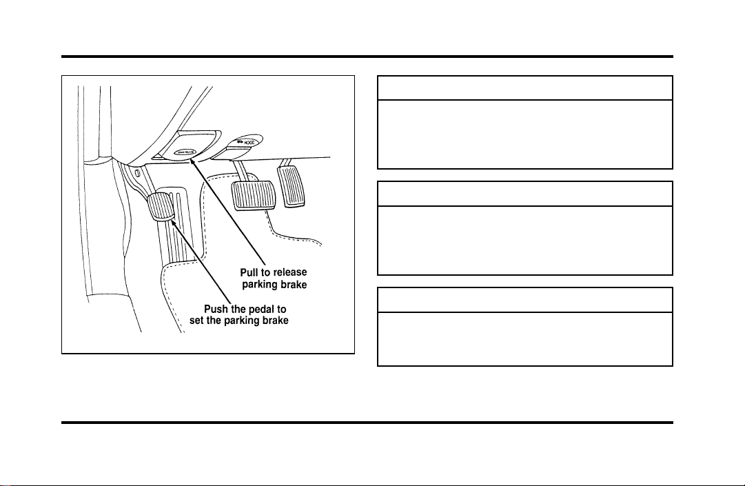
173
Theparkingbrake
WARNING
Alwayssettheparkingbrakefullyand
makesurethegearshiftislatchedinP
(Park).Turnofftheignitionwhenever
youleaveyourvehicle.
WARNING
Iftheparkingbrakeisfullyreleased,
buttheBrakeSystemlightremainson,
havethebrakescheckedimmediately.
Theymaynotbeworkingproperly.
WARNING
Topreventpersonalinjury,donot
releasetheparkingbrakewhileoutside
thevehicle.
File:09fngfc.ex
Update:Fri Sep 6 08:48:49 1996

174
You have an automatic release for the parking
brake. The parking brake should automatically
unlock when you move the gearshift to any forward
gear while the engine is running. However, the
automatic release does not work when the gearshift
is in reverse, neutral or park.
To manually release the parking brake, pull the
BRAKE RELEASE handle located on the lower left
corner of the instrument panel. The Brake Warning
Light will illuminate if the parking brake is not fully
released when the engine is running.
The parking brake is not designed to stop a moving
vehicle, but you can use the parking brake to stop
your vehicle in an emergency if the normal brakes
fail. However, since the parking brake applies only
the rear brakes, the stopping distance will increase
greatly and the handling of your vehicle will be
adversely affected.
Always check the Brake Warning Light each time
you start your engine. Driving with the parking
brake on will cause the brakes to wear out quickly
and will reduce the fuel economy.
Traction Control
TM
Your vehicle is be equipped with the Traction
Control
TM
system. This system helps prevent wheel
spin in order to improve tire traction and is an
especially useful feature when you drive in hilly
areas or on slippery, icy or snowy roads.
When the Traction Control system is controlling
wheelspin, an electric motor sound may be heard
from the engine compartment and engine
acceleration may seem slower. This is normal.
Traction Control
TM
works automatically by rapidly
applying and releasing the brakes and reducing
engine torque to prevent one or both of the front
drive wheels from spinning during acceleration.
File:09fngfc.ex
Update:Fri Sep 6 08:48:49 1996

175
During the Traction Control
TM
function, which most
often occurs during low speed acceleration on
slippery surfaces, a noise may be heard coming from
the engine compartment. This is normal and may
last for a few seconds during the acceleration of the
vehicle.
In general, this system improves your vehicle’s
stability and acceleration performance when road
conditions warrant. Traction Control
TM
is fully
effective at all vehicle speeds.
If the Traction Control
TM
system is cycled
excessively, the brake portion of the system will
shut down to prevent the front brakes from
overheating. A limited Traction Control
TM
function
using engine torque will still control wheels from
spinning. A cooling down period is required to
prevent damage to the brakes. This time period
varies and depends on brake usage during the
cooling down period. Anti-Lock braking is not
affected and will function normally during the cool
down period.
After the cool down period, the full Traction
Control
TM
function is restored.
Rear Air Suspension Adaptive
Ride Control System
Your vehicle has an air suspension system with
automatic rear load leveling and automatic ride
control. This system keeps the rear of your vehicle
at a constant level by adding air or releasing air
from the springs. Ride and handling is enhanced by
firming shock absorber performance during certain
road conditions, steering maneuvers, braking, and
accelerations and is returned to the driver selected
ride calibration when driver or road surface induced
motion changes are completed.
File:09fngfc.ex
Update:Fri Sep 6 08:48:49 1996
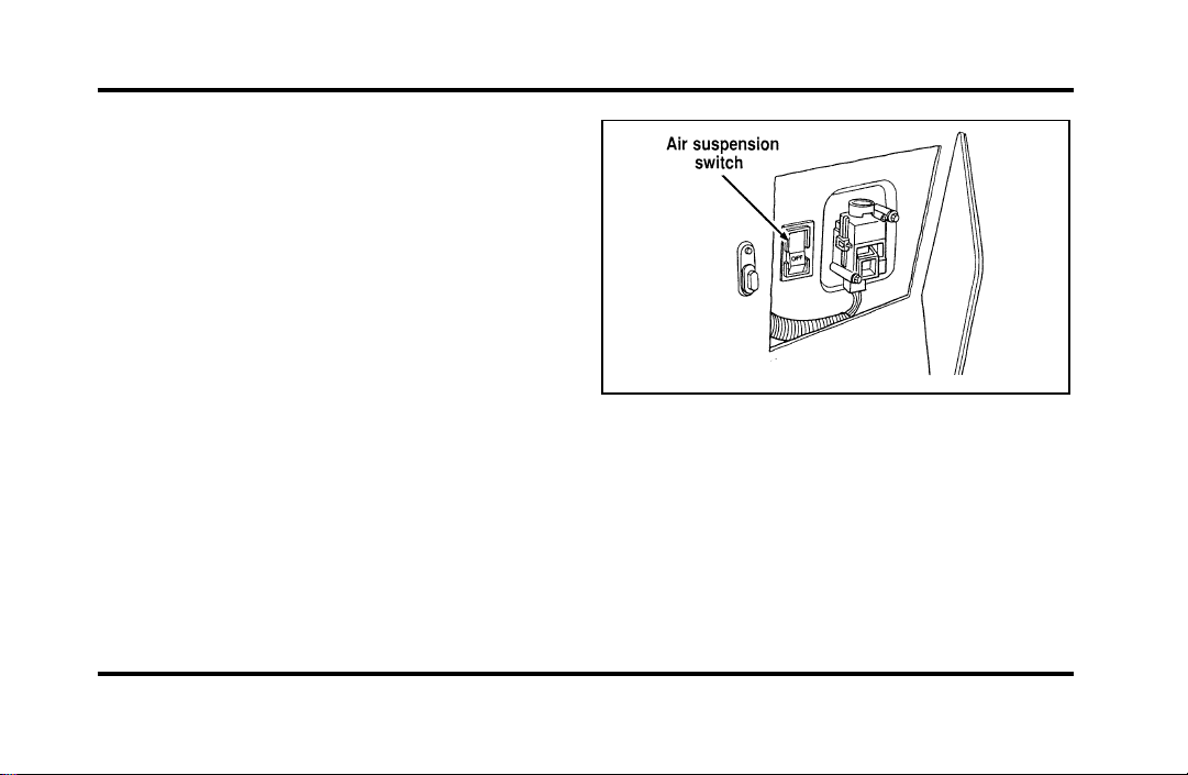
176
A shutoff switch is located behind an access panel
in the left side of the trunk. If this switch is in the
OFF position, the rear air suspension system will
remain at a constant state, not adjusting for varying
loads or driving conditions.
Normal vehicle operation does not require any
action by the driver.
For a more complete listing of the various driving
and steering options available, see Road Calibrated
Suspension in the Features chapter.
The air suspension switch
File:09fngfc.ex
Update:Fri Sep 6 08:48:49 1996

177
Steering Your Vehicle
Your vehicle comes with power steering. Power
steering uses energy from the engine to help steer
your vehicle.
If the amount of effort needed to steer your vehicle
changes, check your steering effort selection in the
Message Center. If this is not the problem, have the
power steering system checked. If the power
steering system breaks down (or if the engine is
turned off), you can steer the vehicle manually but
it takes more effort.
The steering system in your vehicle is speed
sensitive. This means that the steering effort is light
for parking and heavier for highway driving.
However, if you have to swerve around an object
or another vehicle, your steering will have full
power assist.
Never hold the steering wheel to the extreme right
or left for more than five seconds if the engine is
running. This can damage the power steering pump.
Driving with an Automatic
Overdrive Transaxle
Your automatic overdrive transaxle provides fully
automatic operation in either j (Overdrive) or D
(Drive). Driving with the shift selector in j
(Overdrive) gives the best fuel economy for normal
driving conditions. For manual control, start in 1
(First) and then shift manually.
Your vehicle is equipped with an Electronic
Powertrain Control Module that limits engine
and/or vehicle speeds with a cut-out mode to
promote durability.
File:09fngfc.ex
Update:Fri Sep 6 08:48:49 1996
178
PuttingYourVehicleinGear
Yourvehicle’sgearshiftcanbeonthecolumnoron
theconsole.
WARNING
Holdthebrakepedaldownwhileyou
movethegearshiftleverfromposition
toposition.Ifyoudonotholdthe
brakepedaldown,yourvehiclemay
moveunexpectedlyandinjuresomeone.
Tooperate:
1. Starttheengine.
2. Depressandholdthebrakepedal.
3. MovethegearshiftleveroutofP(Park).
4. Depressthethumbbutton(console-mounted
gearshiftonly).
5. MovethegearshiftleveroutofP(Park).
YourvehicleisequippedwithaBrakeShift
Interlocksafetyfeature.Thisfeaturepreventsthe
gearshiftfrombeingmovedfromtheP(Park)
positionuntilthebrakepedalisdepressed.This
featureisactivewhentheignitionisintheON
position.IfthegearshiftleverCANNOTbemoved
fromP(Park)withthebrakepedaldepressed:
1. Turntheengineoffandremovetheignition
key.
2. Applyparkingbrake.
3. Reinserttheignitionkeyandturnclockwiseto
thefirstposition.
4. Depressthebrakepedal,depressthethumb
button(console-mountedgearshiftonly),move
thegearshiftlevertoN(Neutral)andstartthe
engine.
File:09fngfc.ex
Update:Fri Sep 6 08:48:49 1996
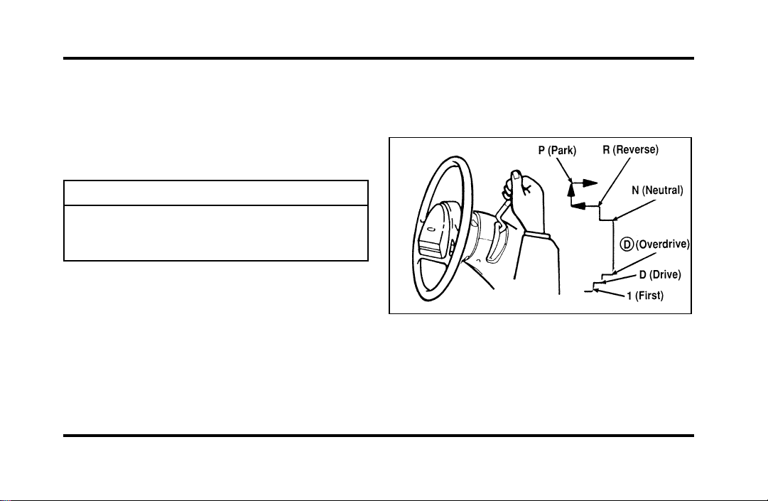
179
IfyouneedtoshiftoutofP(Park)byusingthe
alternateproceduredescribedabove,itispossible
thatafusehasblownandthatyourbrakelamps
mayalsonotbefunctional.Pleaserefertothe
ServicingYourContinentalchapterforinstructions
oncheckingandreplacingfuses.
WARNING
DONOTDRIVEYOURVEHICLE
UNTILYOUVERIFYTHATTHE
BRAKELAMPSAREWORKING.
Usingacolumn-mountedgearshift
Ifyourgearshiftisonthecolumn,youcanuseany
ofthefollowingpositions:
Thepositionsofthecolumn-mountedgearshift
Onceyouplacethegearshiftsecurelyintoposition,
graduallyreleasethebrakepedalandusethe
acceleratorasnecessary.
File:09fngfc.ex
Update:Fri Sep 6 08:48:49 1996

180
Using a console-mounted gearshift
(If equipped)
The console-mounted gearshift
File:09fngfc.ex
Update:Fri Sep 6 08:48:49 1996

181
The console-mounted gearshift thumb button and
brake pedal must be depressed to move the
gearshift lever out of P (Park). The thumb button
pops out automatically when the gearshift latches
into position. Once the gearshift is secure, gradually
release the brake pedal and use the accelerator as
necessary.
Gear Selection (Column- and
Console-Mounted Control)
R (Reverse)
With the gearshift in the R (Reverse) position, the
vehicle will move backward. You should always
come to a complete stop before shifting into or out
of R (Reverse).
N (Neutral)
With the gearshift in the N (Neutral) position, the
vehicle can be started and is free to roll. Hold the
brake pedal down while in this position.
Driving
When to use j (Overdrive)
j (Overdrive) is the usual driving position for an
automatic overdrive transaxle. It works the same
way D (Drive) works, automatically upshifting or
downshifting as the vehicle speeds or slows.
However, j (Overdrive) also shifts into a fourth
gear — an overdrive gear — when your vehicle
cruises at a consistent speed for any length of time.
This fourth gear will increase your fuel economy
when you travel at cruising speeds.
j (Overdrive) may not be appropriate for certain
terrain. If the transaxle shifts back and forth
between third and fourth gears while you are
driving on hilly roads or if your vehicle requires
additional power for climbing hills, shift to D
(Drive).
File:09fngfc.ex
Update:Fri Sep 6 08:48:49 1996

182
When to use D (Drive)
D (Drive) eliminates the excessive shifting between
third and fourth gears that your vehicle sometimes
does when you are traveling through hilly terrain in
j Overdrive. It also gives more engine braking to
slow your vehicle on downgrades than j
Overdrive.
When to use 1 (First)
Use 1 (First) when added engine braking is desired
when descending steep hills.
The automatic transaxle will shift to the proper gear
to ascend any grade without any need to shift to 1
(First).
P (Park)
Always come to a complete stop before you shift
into P (Park). Make sure that the gearshift is
securely latched in P (Park). This locks the transaxle
and prevents the front wheels from rotating.
Always set the parking brake fully and make sure
the gearshift is latched in P (Park). Turn off the
ignition whenever you leave your vehicle.
You can tell a column-mounted gearshift is securely
latched in P (Park) if the lever is adjacent to the P
(Park) and you cannot move it without pulling it
toward you and rotating it downward.
You can tell a console-mounted gearshift is securely
latched in P (Park) if the lever is adjacent to the P
(Park) and you cannot move it without pushing in
the thumb button.
File:09fngfc.ex
Update:Fri Sep 6 08:48:49 1996
183
Thegearshiftwilllockwhenyouturnthekeyto
theLOCKposition.Whenthegearshiftisinany
positionexceptP(Park),theignitionkeycannotbe
turnedtotheLOCKpositionorremovedfromthe
steeringcolumn.Toremovethekey,thegearshift
levermustbeinP(Park).
WARNING
Neverleaveyourvehicleunattended
whileitisrunning.
DrivingWithaHeavyLoad
Therearelimitstotheamountofweightyour
vehiclecancarryortow.Thetotalweightofyour
vehicle,plustheweightofthepassengersand
cargo,shouldneverbemorethantheGrossVehicle
WeightRating(GVWR).Also,theweightthatyour
vehiclecarriesoverthefrontaxleandrearaxle
shouldneverbemorethantheGrossAxleWeight
Rating(GAWR)fortherespectiveaxle.
Youcanfindyourvehicle’sGVWRandGAWRon
theSafetyComplianceCertificationLabelontheleft
frontdoorlockfacingoronthedoorlatchpost
pillar.
Theweightlimitsofyourvehicle’stiresaffectthe
GVWRorGAWRlimitations.Usageofreplacement
tireswithhigherweightlimitsthanoriginalsdoes
notincreaseGVWRorGAWR.Usageoflower
capacityreplacementtiresmaylowerGVWRand
GAWRlimitations.
WARNING
DonotexceedtheGVWRorthe
GAWRspecifiedontheSafety
ComplianceCertificationLabel.
File:09fngfc.ex
Update:Fri Sep 6 08:48:49 1996

184
Limiting Your Vehicle’s Load
The load that you add to your vehicle must not
exceed the maximum load stated on the Safety
Compliance Certification Decal attached to the left
front door pillar.
To figure the weight of your vehicle’s load, add the
weights of:
❑
the driver and passengers
❑
luggage and any other items that you put in
your vehicle
❑
the tongue load of the loaded trailer
❑
the weight of any equipment that has been
added to your vehicle since it was delivered to
your dealer
If you do not know the actual weights of these
items, use the following procedure to figure the
weight of a load:
1. Weigh your vehicle without the driver,
passengers and luggage. You might take your
vehicle to a shipping company or an inspection
station for trucks.
2. Then weigh your vehicle with the driver,
passengers and luggage.
3. Subtract the first reading from the second to
figure the total weight of the load.
After determining this load, you must also make
sure that the total weight of your vehicle, plus the
load it carries, is less than its GVWR. Also, make
sure that the weight your vehicle carries over each
axle is less than the GAWR for the respective axle.
File:09fngfc.ex
Update:Fri Sep 6 08:48:49 1996

185
IfyourvehicleexceedstheGVWR,removecargo
fromyourvehicleaccordingly.Ifyourvehicle
exceedstheGAWRforeitheraxle,shifttheloador
removecargoaccordingly.
WARNING
Improperdistributionofyourvehicle’s
loadorcarryingweightinexcessofthe
amountshownonthetiredecalcan
causerapidtirewearorlossofvehicle
control.
TrailerTowing
Yourvehicleiscapableoftowingatrailerofupto
amaximumof2,000lbs.(907kg)grosstrailer
weightwithamaximumtongueloadof200lbs.
(91kg).
Becausetowingatrailerputsextrastrainonyour
vehicle,youmustfollowcertainprecautionsfor
yoursafetyandthegoodofyourvehicle:
❑
Staywithintheloadlimitsfortowingyour
vehicle.(SeeTrailertowingspecificationsinthis
chapter.)
❑
Carefullyandthoroughlyprepareyourvehicle
fortowing,makingsuretousetheright
equipmentandtoattachitproperly.(See
PreparingtoTowinthischapter.)
❑
Useextracautionwhendrivingyourvehicle
whileyoutow.(SeeDrivingwhileyoutowin
thischapter.)
❑
Serviceyourvehiclemorefrequentlyifyoutow
atrailer.(SeeServicingyourvehicleifyoutow
inthischapter.)
Tento15%oftheloadedtrailer’sweightshouldbe
onthetongue.However,thetongueloadshould
neverexceed10%ofthemaximumweightthat
yourvehiclecansafelytow.
Newvehiclesshouldbedriven2,000miles
(3,200km)beforetowingatrailer.
File:09fngfc.ex
Update:Fri Sep 6 08:48:49 1996
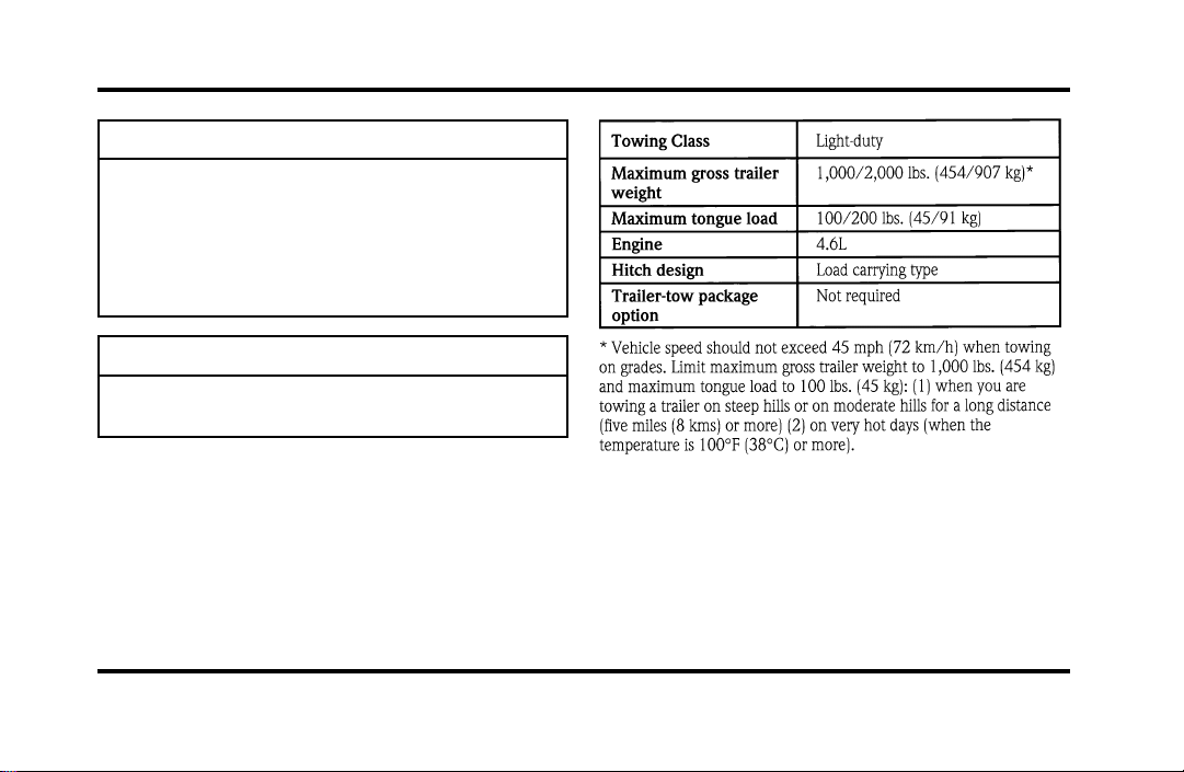
186
WARNING
Towingtrailersbeyondthemaximum
recommendedgrosstrailerweight
exceedsthelimitofthevehicleand
couldresultinenginedamage,transaxle
damage,structuraldamage,lossof
control,andpersonalinjury.
WARNING
Donottowatrailerwhenusinga
temporarysparetire.
Seethefollowingchartfortheamountofweight
yourvehiclecantow.
Youshouldalsolimityourtrailer’sloadwhenyou
towinhighaltitudes.
File:09fngfc.ex
Update:Fri Sep 6 08:48:49 1996

187
Preparing to Tow
For your safety and for the good of your vehicle,
use the right equipment for the type of trailer you
tow. Also, make sure that all towing equipment is
properly attached to your vehicle. If you are not
certain that you are using the right equipment in
the proper manner, see your Ford or
Lincoln-Mercury dealer.
Do not use hitches that clamp onto your vehicle’s
bumper. The bumper is not designed to bear the
load.
Always check the pressure in all your vehicle’s tires
when preparing to tow (see inflation
recommendation on the tire label).
Connecting the safety chains
Always attach the trailer’s safety chains to your
vehicle. They help protect your trailer if the hitch
breaks.
To connect the trailer’s safety chains:
1. Cross the chains under the trailer tongue and
attach them to your vehicle’s frame or hook
retainers. Never attach the safety chains to your
vehicle’s bumper. The bumper is not designed
to bear the weight of a trailer.
2. Make sure that you leave enough slack in the
chains to allow you to turn corners.
If you use a rental trailer, follow the instructions
that the rental agency gives you.
File:09fngfc.ex
Update:Fri Sep 6 08:48:49 1996

188
Connectingthetrailer’sbrakes
Electricbrakesandmanual,automatic,orsurge-type
hydraulicbrakesaresafeifyouinstallthemproperly
andadjustthemaccordingtothemanufacturer’s
instructions.Besurethatyourtrailer’sbrakesmeet
localandfederalregulations.
Separatetrailerbrakesofadequatesizeshould
beusedfortrailersweighingover1,000lbs.
(454kg)loadedweight.
WARNING
Donotconnectatrailer’shydraulic
brakesystemdirectlytoyourvehicle’s
brakesystem.Yourvehiclemaynot
haveenoughbrakingpowerandyour
chancesofhavingacollisiongreatly
increase.
Connectingthetrailer’slights
Donotconnectatrailer’slightingsystem
wiringdirectlytoyourvehicle’slightingsystem
wiring.Togettheproperequipmentforhooking
upyourtrailer’slights,seeyourlocaltrailerdealer
andyourForddealer.Besuretofollowtheir
instructionscarefully.
Ifyoudonotinstalltrailerlightscorrectly,youmay
causedamagetothevehicle’slightingsystem.
File:09fngfc.ex
Update:Fri Sep 6 08:48:49 1996

189
Driving While You Tow
Be especially careful when driving while you tow a
trailer. Never drive faster than 45 mph (70 km/h)
when you tow in hilly country on hot days. Also,
anticipate stops so that you can brake gradually.
Towing a trailer increases the load on the engine
and transaxle, particularly in hilly country and with
heavier trailers. Under these conditions you may
experience an excessive amount of shifting between
Overdrive and Third gears. Moving the shift selector
to D (Overdrive Lockout) will keep this from
happening and will provide better engine braking.
When driving in less hilly country or with a lighter
trailer load, you may move the gearshift selector
lever to j (Overdrive) without experiencing
excessive shifting.
When driving down steep hills, you should put the
gearshift selector lever in the 1 (First) position to
shift the transaxle into second gear. This will
provide additional engine braking.
The automatic transaxle will automatically
downshift to the proper gear for driving up a grade.
If you use the speed control while you are towing
on very long, steep grades, the speed control may
shut off.
Servicing Your Vehicle If You Tow
If you tow a trailer for a long distance, your vehicle
will need to be serviced more frequently than usual.
Refer to the Maintenance Schedule booklet for
additional information.
File:09fngfc.ex
Update:Fri Sep 6 08:48:49 1996
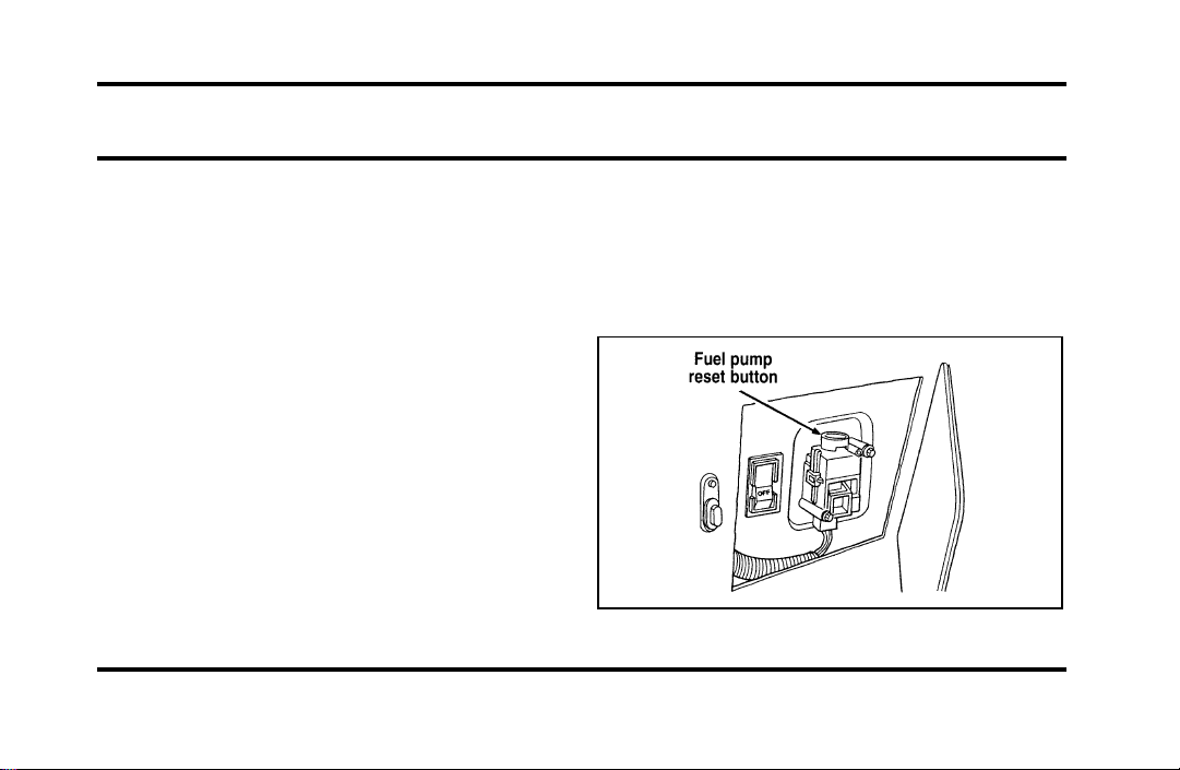
191
Roadside Emergencies
Hazard Flashers
The flashers work whether your vehicle is running
or not. The flashers work for up to two hours
when the battery is fully charged and in good
condition without draining the battery excessively. If
the flashers run for longer than two hours or if the
battery is not fully charged, the battery can be
drained.
If the Engine Cranks but Does
Not Start or Does Not Start After
a Collision
Fuel Pump Shut-off Switch
If the engine cranks but does not start even after a
small collision, the fuel pump shut-off switch may
have been actuated. The shut-off switch is a device
intended to stop the fuel pump when your vehicle
has been involved in a substantial jolt.
Once the shut-off switch is actuated, you must reset
the switch by hand before you can start your
vehicle. The switch is on the left side of the trunk.
The left side of the trunk
File:10fnerc.ex
Update:Fri Sep 6 08:49:57 1996

192
WARNING
Ifyouseeorsmellfuel,donotreset
theswitchortrytostartyourvehicle.
Haveallthepassengersgetoutofthe
vehicleandcallthelocalfire
departmentoratowingservice.
Ifyourenginecranksbutdoesnotstartaftera
collisionorsubstantialjolt:
1. TurntheignitionkeytotheOFFposition.
2. Checkunderthevehicleforleakingfuel.
3. Ifyoudonotseeorsmellfuel,pushthered
resetbuttondown.Ifthebuttonisalreadyset,
youmayhaveadifferentmechanicalproblem.
4. TurntheignitionkeytotheONpositionfora
fewseconds,thenturnittotheOFFposition.
5. Checkunderthevehicleagainforleakingfuel.
Ifyouseeorsmellfuel,donotstartyour
vehicleagain.Ifyoudonotseeorsmellfuel,
youcantrytostartyourvehicleagain.
Fuses
Fuses(conventionalandhighcurrent)protectyour
vehicle’selectricalsystemfromoverloading.If
electricalpartsinyourvehiclearenotworking,the
systemmayhavebeenoverloadedandblowna
fuse.Beforeyoureplaceorrepairanyelectrical
parts,checktheappropriatefuses(conventionaland
highcurrent).
Thefollowingchartstellyouwhichfusesprotect
eachelectricalpartofyourvehicle.Ifafuseblows,
allthepartsofyourvehiclethatusethatcircuit
willnotwork.
Onceyouhavedeterminedwhichfusestocheck,
followtheproceduresunderCheckingand
replacingfusesinthischapter.
File:10fnerc.ex
Update:Fri Sep 6 08:49:57 1996
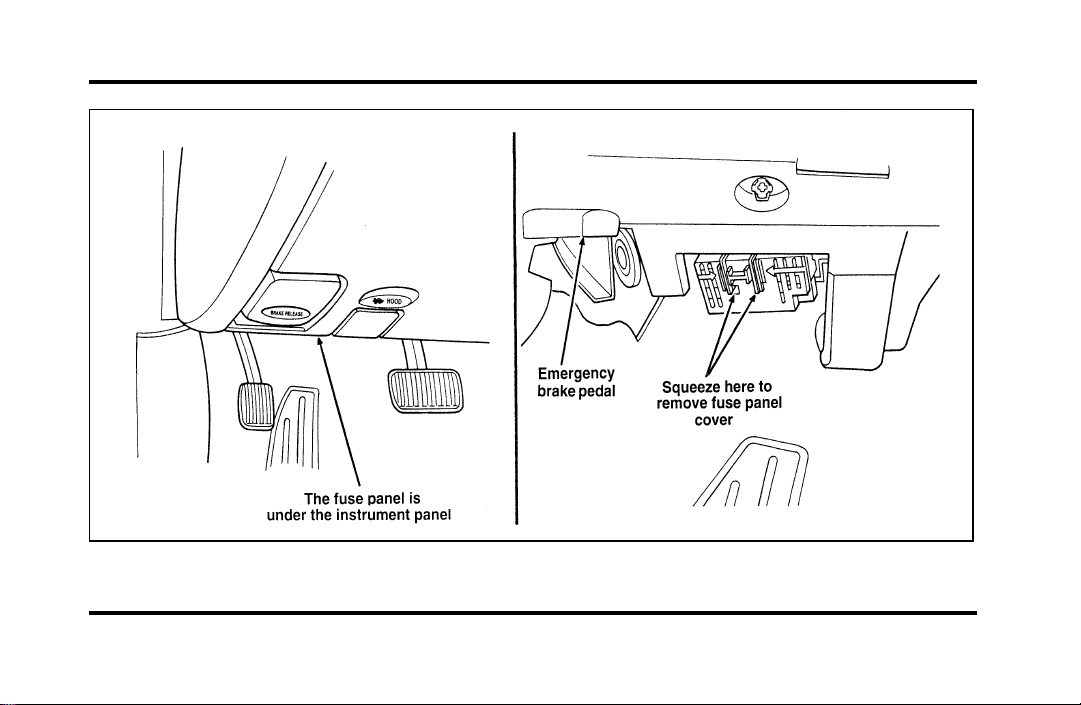
193
The instrument panel fuse panel location
File:10fnerc.ex
Update:Fri Sep 6 08:49:57 1996
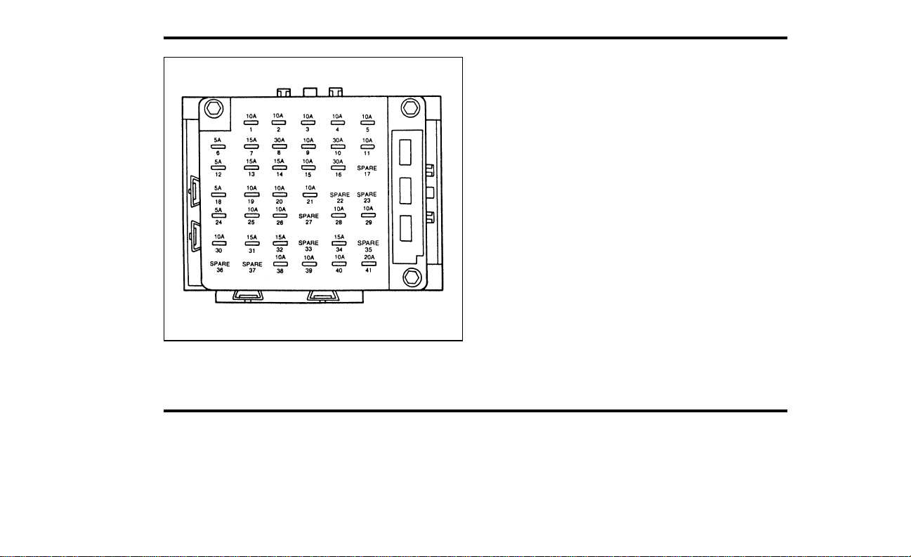
194
The instrument panel fuse panel
File:10fnerc.ex
Update:Thu Jun 20 15:19:51 1996

195
The Instrument Panel Fuses
File:10fnerc.ex
Update:Fri Sep 6 08:49:57 1996

196
File:10fnerc.ex
Update:Fri Sep 6 08:49:57 1996

197
File:10fnerc.ex
Update:Fri Sep 6 08:49:57 1996
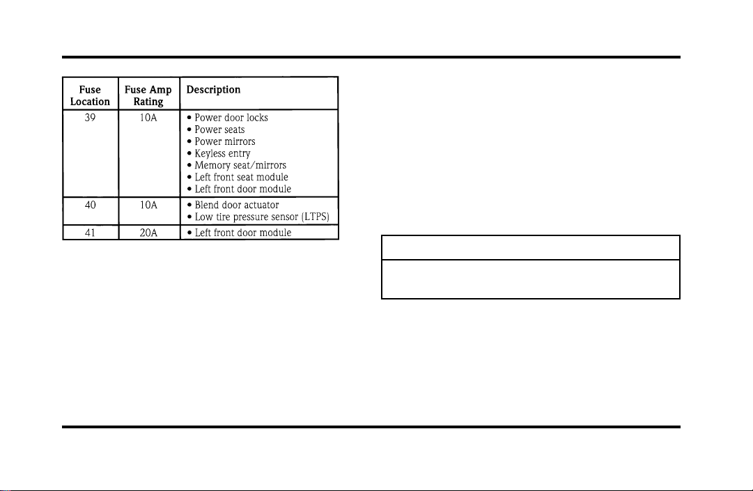
198
HighCurrentFuses
Highcurrentfusesarecircuitprotectorsthatare
partofthewiringharnessforsomeelectrical
equipment.These,likefuses,openwhenthecircuit
loadexceedstheiramperagerating.Highcurrent
fusesmaybepurchasedfromyourFordor
Lincoln-Mercurydealer.
Thehighcurrentfusepanelislocatedintheengine
compartmentontheleft-handfenderapron.
WARNING
Alwaysdisconnectthebatterybefore
servicinghighcurrentfuses.
Fordrecommendsthathighcurrentfusesbe
replacedbyaqualifiedtechnician.
File:10fnerc.ex
Update:Fri Sep 6 08:49:57 1996
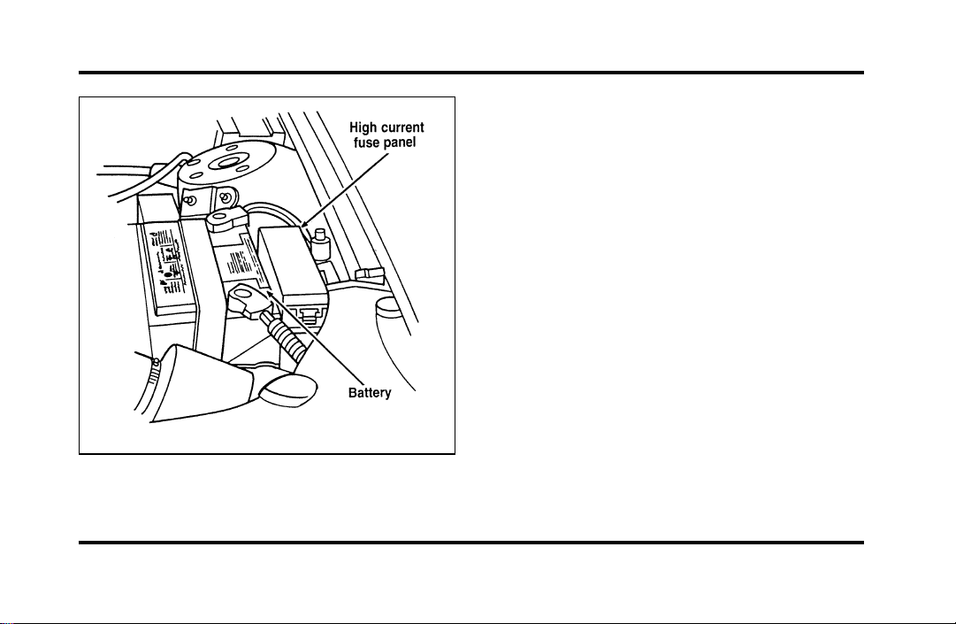
199
The high current fuse panel location
File:10fnerc.ex
Update:Fri Sep 6 08:49:57 1996
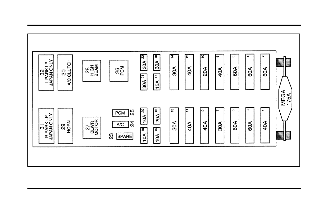
200
The high current fuse panel
File:10fnerc.ex
Update:Fri Sep 6 08:49:57 1996

201
The high current fuses
File:10fnerc.ex
Update:Fri Sep 6 08:49:57 1996

202
File:10fnerc.ex
Update:Fri Sep 6 08:49:57 1996
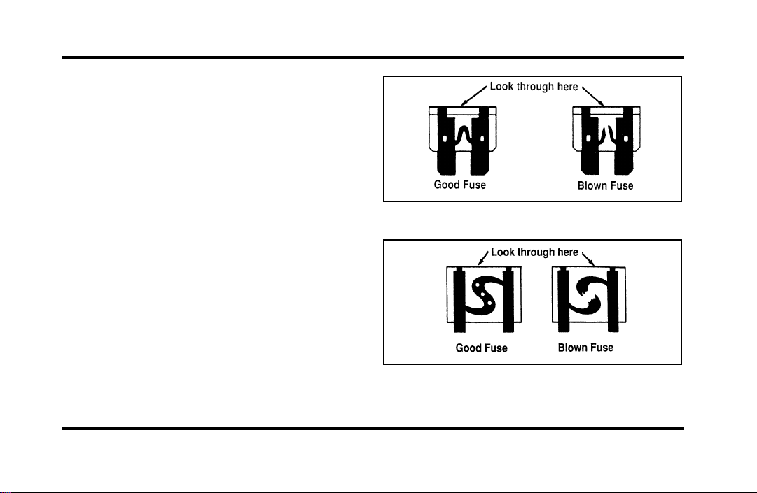
203
Checking and Replacing Fuses
If you need to check a fuse, follow these steps:
1. Find the fuse panel underneath the instrument
panel to the left of the steering column.
Squeeze together the two areas indicated by
the arrows and pull down to remove the cover.
2. Find the fuse you want to check (fuses are
numbered on the fuse panel) and remove it
with the fuse pulling tool that is provided.
3. Check the fuse to see if it is blown. Look
through the clear side of the fuse to see if the
metal wire inside is separated. If it is, the fuse
should be replaced.
The side view of a Blade type fuse
The side view of a high current fuse
File:10fnerc.ex
Update:Fri Sep 6 08:49:57 1996
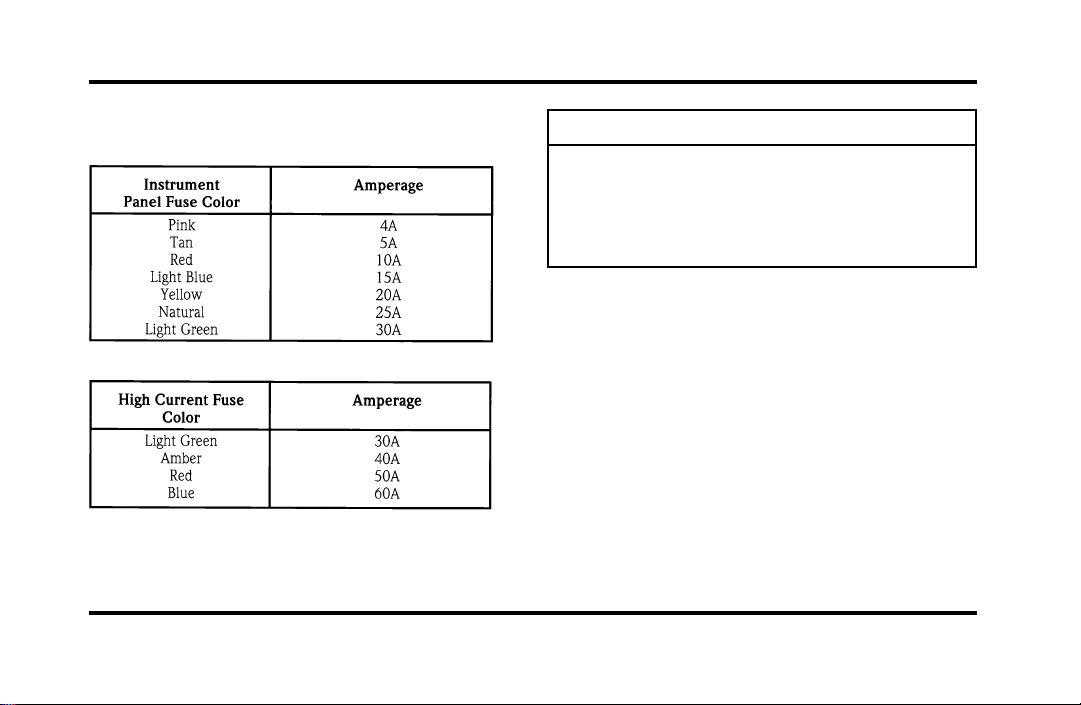
204
4. Replacethefusewithonethathastheright
amperagerating.(Seethefollowingcharts.)
WARNING
Alwaysreplaceafusewithonethathas
thespecifiedamperagerating.Usinga
fusewithahigheramperageratingcan
causeseverewiredamageandcould
startafire.
5. Aligntheedgeofthecoverwiththeedgeof
thefusepanelandpushthecoverupuntilit
latches.
Evenafteryoureplaceafuse,itmaycontinueto
blowifyoudonotfindwhatcausedtheoverload.
Ifthefusecontinuestoblow,haveyourelectrical
systemchecked.
File:10fnerc.ex
Update:Fri Sep 6 08:49:57 1996

205
ChangingaTire
Ifyougetaflattirewhileyouaredriving,donot
applythebrakeheavily.Instead,graduallydecrease
thespeed.Holdthesteeringwheelfirmlyand
slowlymovetoasafeplaceonthesideoftheroad.
Parkonalevelspot,turnofftheignition,setthe
parkingbrake,andturnonthehazardflashers.
TheTemporarySpareTire
Youmayhaveahighpressuretemporarysparetire.
Thissparetireissmallerthanaregulartireandis
designedforemergencyuseonly.Useitonlywhen
yougetaflattireandreplaceitassoonasyoucan.
Thissparetireismarkedwiththewords
“TEMPORARYUSEONLY”sothatyoucaneasily
identifyit.
WARNING
Ifyouusethetemporarysparetire
continuouslyordonotfollowthese
precautions,thetirecouldfail,causing
youtolosecontrolofthevehicle,
possiblyinjuringyourselforothers.
Whenyoudrivewiththetemporarysparetire,
DONOT:
❑
exceed50mph(80km/h)underany
circumstances.
❑
loadyourvehiclesothatitisheavierthanthe
maximumvehicleloadratinglistedonthetire
decal.
❑
towatrailer.
❑
trytorepairthetemporarysparetireorremove
itfromitswheel.
File:10fnerc.ex
Update:Fri Sep 6 08:49:57 1996
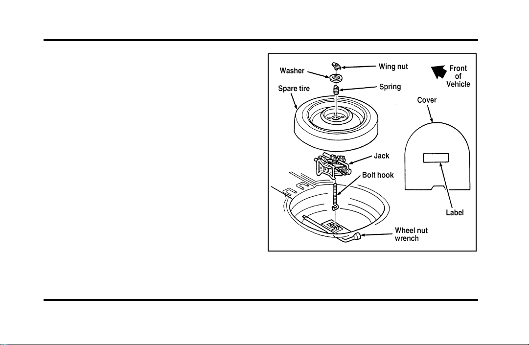
206
❑
use the wheel for any other type of vehicle.
❑
drive through an automatic car wash with this
tire. Because the temporary spare tire is smaller
than a conventional tire, it reduces the ground
clearance. Your vehicle may get caught in the
rails and it could be damaged.
Spare Tire Location
The spare tire is stored under the carpet on the
floor of the trunk.
You will find additional instructions for the spare
tire on the warning label located on the wheel and
the jacking instructions located on the spare tire
cover.
The spare tire location
File:10fnerc.ex
Update:Fri Sep 6 08:49:57 1996
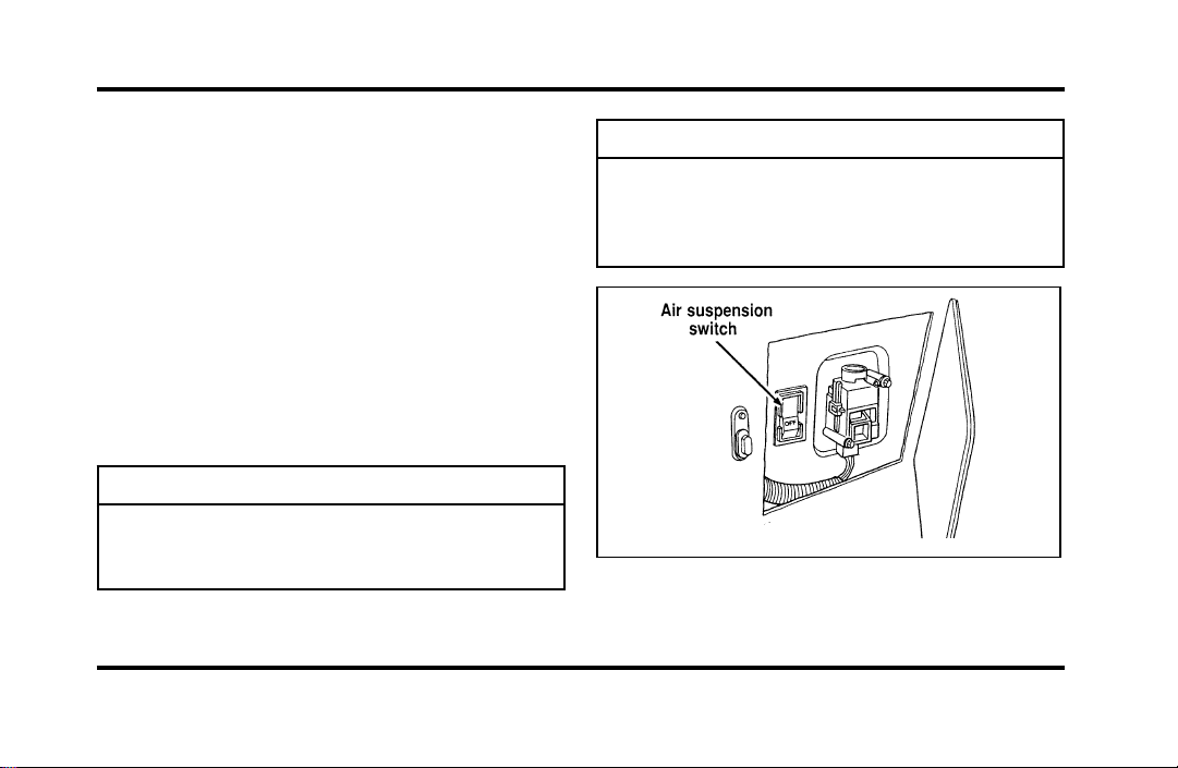
207
Toremovethesparetire:
1. Removethesparetirecover.
2. Unscrewthewing-nutholdingdownthespare
tire.
3. Liftoutthesparetireandjackkit.
PreparingtoChangetheTire
1. Makesurethatyourvehiclewillnotmoveor
roll.PutthegearshiftinP(Park).Setthe
parkingbrakeandblockthewheelthatis
diagonallyoppositethetirethatyouare
changing.
WARNING
Ifthevehicleslipsoffthejack,youor
someoneelsecouldbeseriously
injured.
Turnofftheairsuspensionswitchpriortojacking.
WARNING
OnvehiclesequippedwithAir
Suspension,turnOFFtheAir
Suspensionswitchpriortojacking,
hoistingortowingyourvehicle.
Theairsuspensionswitch—locatedinthe
trunk
File:10fnerc.ex
Update:Fri Sep 6 08:49:57 1996
208
2. Getoutthesparetireandjack.
WARNING
Toavoidinjury,neverruntheengine
withonewheelofftheground,suchas
whenchangingatire.
3. Removethecenterornamentfromthe
aluminumwheelwiththetaperedendofthe
wheelnutwrenchwhichcamewithyour
vehicle.Insertandtwistthehandle,thenpry
againstthewheel.
4. Looseneachwheellugnutone-halfturn
counterclockwise,butdonotremovethem
untilthetireisraisedofftheground.You
shouldpulluponthehandleratherthanpush
todevelopmaximumforcetoloosenwheellug
nuts.SeeAnti-TheftWheelLugNutslaterin
thischapterforinformationonremoving
anti-theftlugnuts.
RemovingandReplacingtheTire
1. Placethescissors-typejackunderthesideof
thevehicleandadjustthejackheightwiththe
jackhandle.Thejackshouldfitinthenotchin
theverticalrockerpanelflangewhichisnearest
tothewheeltobechanged.
WARNING
Tolessentheriskofpersonalinjury,
donotputanypartofyourbodyunder
thevehiclewhilechangingatire.Do
notstarttheenginewhenyourvehicle
isonthejack.Thejackisonlymeant
forchangingthetire.
File:10fnerc.ex
Update:Fri Sep 6 08:49:57 1996
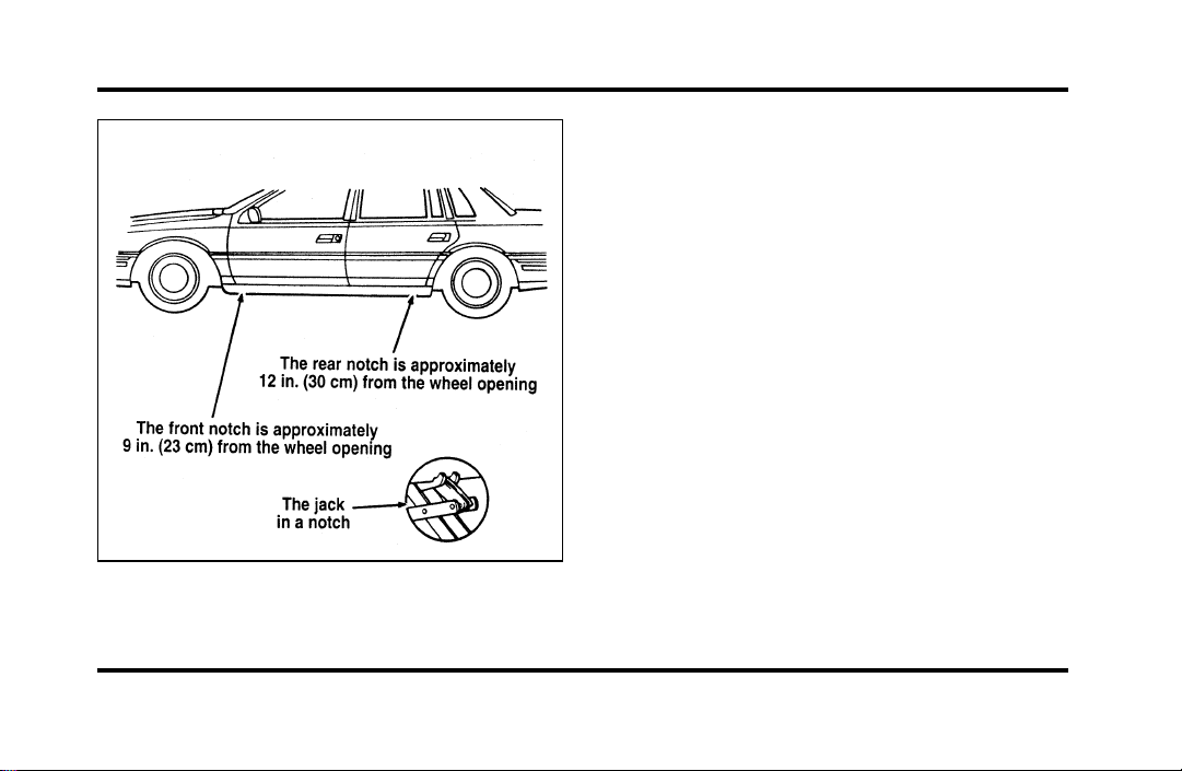
209
The notches for the jack
2. Turn the jack handle clockwise until the wheel
clears the ground. Remove the wheel lug nuts.
3. Replace the flat tire with the spare tire, making
sure that the air valve stem is facing outward.
4. Reinstall the lug nuts, tightening until the
wheel is snug against the hub. The beveled
edges on the lug nuts face inward. Do not fully
tighten the lug nuts until you lower the
vehicle. If you do, you could force the vehicle
off the jack.
5. Lower the vehicle by turning the jack handle
counterclockwise.
6. Remove the jack and fully tighten the lug nuts
in the order shown in the following illustration.
As soon as possible, have your dealer or a
qualified service technician check the lug nuts
for proper torque specifications.
File:10fnerc.ex
Update:Fri Sep 6 08:49:57 1996

210
The lug nuts on the wheel
7. Place any ornaments in the trunk.
8. Put the tire, jack, and wrench away. Make sure
the jack is securely fastened so it does not
rattle when you drive.
9. Unblock the wheels.
10. Turn on the air suspension switch.
After replacing a flat tire with the temporary spare
tire, the flat tire can be secured in the trunk tub by
placing the “J” hook through a lug nut hole in the
wheel with the tire and wheel lying at an angle.
Anti-Theft Wheel Lug Nuts
(If equipped)
If your vehicle has this option, one of the lug nuts
on each wheel locks and must be unlocked with a
special key. The key and registration card are
attached to the lug wrench and stored with the
spare tire. If you lose the key, send the registration
card to the manufacturer (not the dealer) to get a
replacement key.
NOTE: If entire lug wrench/lug nut key assembly
is lost, see your nearest Ford or Lincoln-Mercury
dealer who has access to a master set of keys.
NOTE: DO NOT USE A POWER IMPACT
WRENCH ON THE LUG NUT KEY.
File:10fnerc.ex
Update:Fri Sep 6 08:49:57 1996
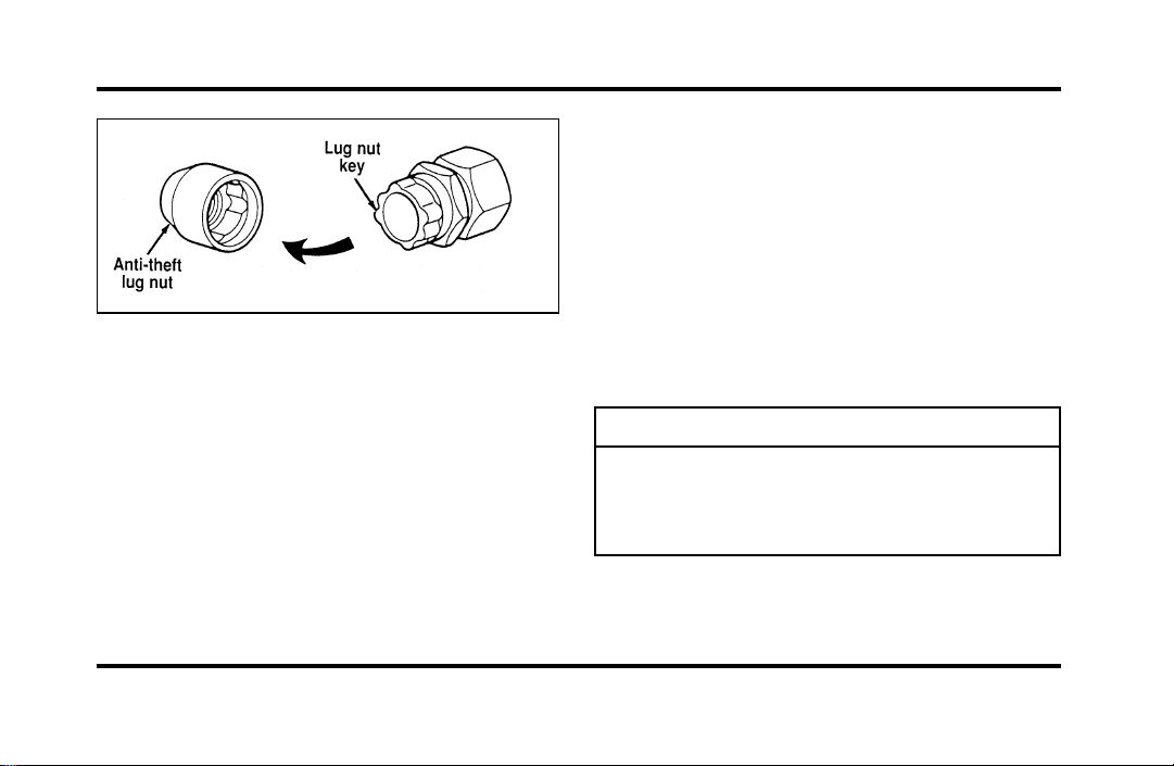
211
Theanti-theftlugnutandkey
Removingtheanti-theftlugnut
Insertthekeyoverthelockinglugnut.Makesure
thatyouholdthekeysquaretothelugnut.Ifyou
holdthekeyonanangle,youmaydamagethekey
andthelugnut.
Placethelugnutwrenchoverthelugnutkeyand
applypressureonthekeywiththewrench.Turn
thewrenchinacounterclockwisedirectionto
removethelugnut.
Reinstallingtheanti-theftlugnut
Insertthekeyoverthelockinglugnut.Placethe
lugnutwrenchoverthelugnutkeyand,while
applyingpressureonthekey,installthelugnut.
Jump-StartingYourVehicle
Yourvehicle’sbatterymaydieifyouleavethe
lightsonoranyelectricalequipmentonafteryou
turntheengineoff.Ifthishappens,youmaybe
abletojump-startyourvehiclewithabooster
battery.
WARNING
Thegasesaroundthebatterycan
explodeifexposedtoflames,sparks,or
litcigarettes.Anexplosioncouldresult
ininjuryorvehicledamage.
File:10fnerc.ex
Update:Fri Sep 6 08:49:57 1996
212
WARNING
Toprotectyourselfwhencharginga
battery,alwaysshieldyourfaceand
eyes.Makesurethatyoucanbreathe
freshair.
WARNING
Applyingtoomuchpressureonthe
endswhenliftingabatterycouldcause
acidtospill.Liftthebatterywitha
carrierorwithyourhandsonthe
oppositecorners.
WARNING
Batteriescontainsulfuricacidwhich
burnsskin,eyes,andclothing.
Iftheacidtouchessomeone’sskin,eyes,or
clothing,immediatelyflushtheareawithwaterfor
atleast15minutes.Ifsomeoneswallowstheacid,
havehimorherdrinklotsofmilkorwaterfirst,
thenMilkofMagnesia,abeatenegg,orvegetable
oil.Calladoctorimmediately.
Toavoiddamagingyourvehicleoryourbattery,
andtoavoidinjurytoyourself,followthese
directionsforpreparingyourvehicletojump-start
andconnectingthejumpercablesintheorderthey
aregiven.Ifindoubt,callforroadservice.
File:10fnerc.ex
Update:Fri Sep 6 08:49:57 1996

213
Preparing Your Vehicle
1. Your vehicle has a 12-volt starting system, so
you need to use a 12-volt jumper system. You
will damage your starting motor, ignition
system, and other electrical parts if you connect
them to a 24-volt power supply (either two
12-volt batteries in series or a 24-volt generator
set).
2. Do not disconnect the battery of the disabled
vehicle. You could damage the vehicle’s
electrical system.
3. Park the booster vehicle close to the hood of
the disabled vehicle. Make sure the vehicles
do not touch each other. Set the parking
brake on both vehicles and stay clear of the
engine cooling fan and other moving parts.
4. Check all battery terminals and remove any
excessive corrosion before you attach the
jumper cables.
5. Turn on the heater fan in both vehicles. Press
the DEFROST button. Turning on the fan helps
protect the electrical system from voltage
surges. Turn off all other switches and gauges.
File:10fnerc.ex
Update:Fri Sep 6 08:49:57 1996
214
Connectingthejumpercables
1. Connectoneendofthefirstjumpercableto
thepositive(+)terminalofthedischarged
battery.(Youcanconnecteitherjumpercable
tothepositive(+)terminal,aslongasyouuse
thesamecableforbothpositiveterminals.)
Mostjumpercableshavearedcableanda
blackcable.Theredcableisgenerallyusedfor
thepositiveterminalsandtheblackforthe
negativeones.
2. Connecttheotherendofthefirstcabletothe
positive(+)terminaloftheboosterbattery.
3. Connectoneendofthesecondcabletothe
negative(s)terminaloftheboosterbattery—
NOTtothedischargedbattery.
4. Connecttheotherendofthesecondcabletoa
goodmetallicsurfaceontheengineorframeof
thedisabledvehicle.
WARNING
Donotconnecttheendofthesecond
cabletothenegative(s)terminalofthe
batterytobejumped.Asparkmay
causeanexplosionofthegasesthat
surroundthebattery.
File:10fnerc.ex
Update:Fri Sep 6 08:49:57 1996
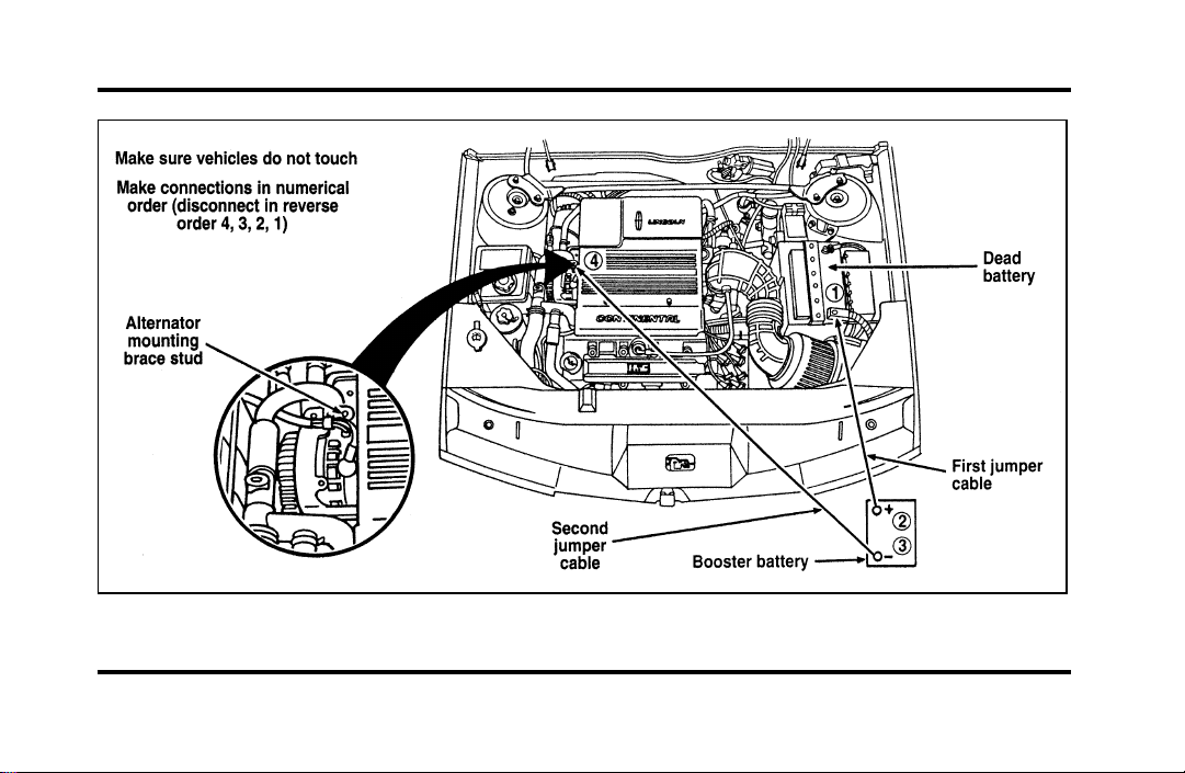
215
The engine with jumper cables
File:10fnerc.ex
Update:Fri Sep 6 08:49:57 1996

216
Jump-Starting
1. Make sure that the jumper cables are not in
the way of moving engine parts, then start the
booster vehicle. Run the engine at a moderate
speed.
2. Let the discharged battery charge for a few
minutes and then start the disabled vehicle. It
may take a couple of tries before the vehicle
starts. If the vehicle does not start after several
attempts, there may be a different problem.
3. When both vehicles are running, let them idle
for a few minutes to charge the discharged
battery.
Removing jumper cables
1. Always remove the jumper cables in the
reverse order. Remove the negative (s) end
of the jumper cable from the metallic surface
on the engine or frame of the disabled vehicle.
2. Remove the negative (s) cable from the
booster battery.
3. Remove the positive (+) cable from the booster
battery.
4. Remove the other end of the positive (+) cable
from the discharged battery.
After the vehicle is started, let it idle for a while to
let the engine “relearn” its idle conditions. Drive it
around for a while with all electrical accessories
turned off to let the battery recharge. Driveability
may be deteriorated slightly until all drive modes
are “relearned.” You may need to use a battery
charger to fully recharge the battery.
If you need to replace your battery, see Battery in
the Maintenance and Care chapter.
File:10fnerc.ex
Update:Fri Sep 6 08:49:57 1996
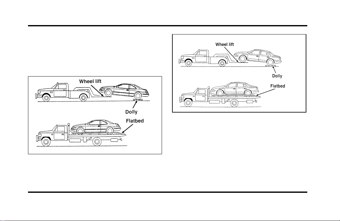
217
Towing Your Vehicle
If you need to have your vehicle towed, contact a
professional towing service or, if you are a member,
your roadside assistance center. Typical towing
options include wheel lift towing or flat bed towing.
Front towing
File:10fnerc.ex
Update:Fri Sep 6 08:49:57 1996
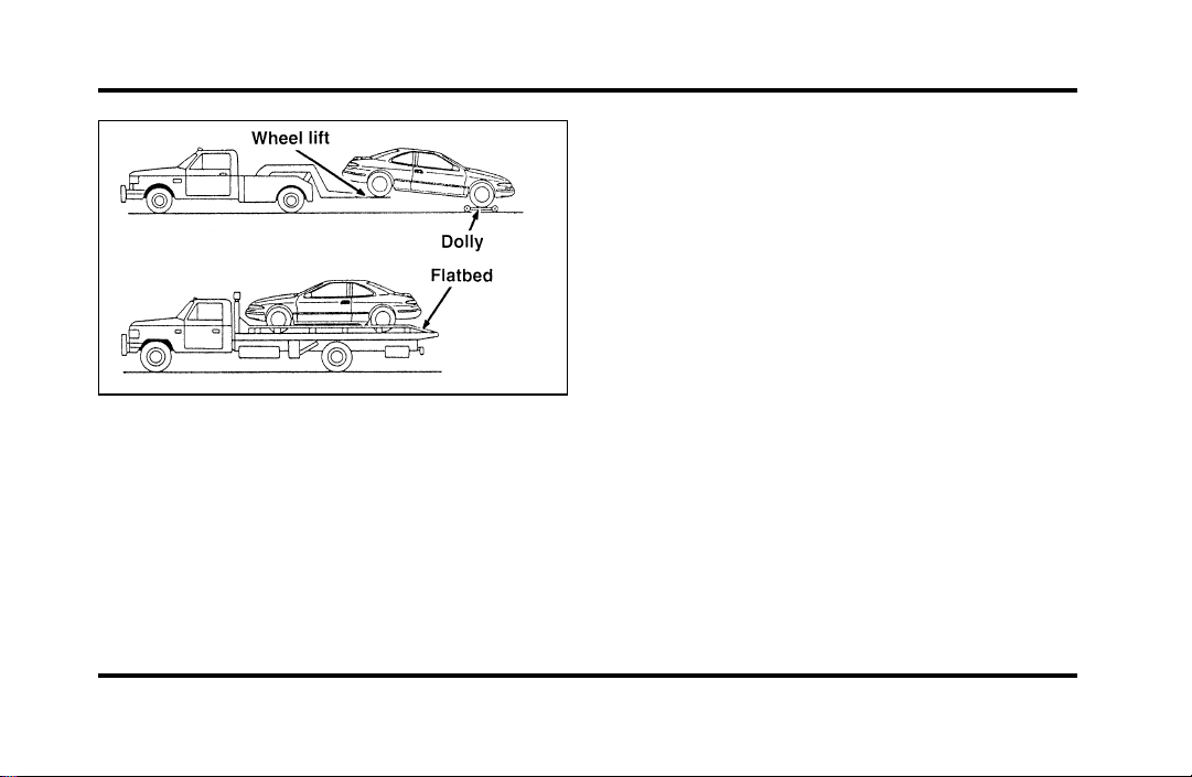
218
Rear towing
When calling for a tow truck, tell the operator what
kind of vehicle you have. A towing manual is
available from Ford Motor Company for all
authorized tow truck operators. Have your tow
truck driver refer to this manual for the proper
hook-up and towing procedures for your vehicle.
Lincoln RESCU System
(If equipped)
The Lincoln RESCU buttons, located in the
overhead console, should be used in the event that
you require roadside assistance (out of gas, need a
tow, etc.) or emergency assistance (involved in an
accident, report a crime or fire, require medical
attention, etc.).
See Lincoln RESCU System in the Features chapter
for more information.
File:10fnerc.ex
Update:Fri Sep 6 08:49:57 1996

219
Maintenance and Care
Service Made Easy
Ford has two goals for servicing your vehicle.
1. When we can, we design parts that do not
need to be serviced.
2. We want to make servicing your vehicle as
easy as possible. To help you:
❑
We highlight do-it-yourself items in yellow in
the engine compartment so that you can find
them easily.
❑
When possible, we design parts that can be
replaced without tools.
❑
We give you a Maintenance Schedule that
makes tracking routine service for your vehicle
easy. The maintenance schedule is located in
the Maintenance Schedule booklet.
This chapter tells you about the basic parts that you
need to check and service regularly.
If your vehicle needs professional servicing, your
dealership can provide the parts and service
required. Check your Warranty Information Booklet
to find out which parts and services are covered.
Also see the Customer Assistance chapter of this
Owner Guide.
Ford Motor Company recommends that the Owner
Maintenance Checks listed in the Maintenance
Schedule booklet be performed for the proper
operation of your vehicle. In addition to the
conditions listed in the Owner Maintenance
Checklist, be alert for any unusual noise, vibration,
or other indication that your vehicle may need
service. If you do notice something unusual, see
that your vehicle is serviced promptly.
File:11fnmcc.ex
Update:Fri Sep 6 08:51:16 1996

220
Use only recommended fuels, lubricants, fluids, and
service parts conforming to Ford specifications.
Motorcraft parts are designed and built to provide
the best performance in your vehicle. Using these
parts for replacement is your assurance that
Ford-built quality stays in your vehicle.
NOTE: Always dispose of used automotive fluids in
a responsible manner. Follow your community’s
standards for disposing of these types of fluids. Call
your local recycling center to find out about
recycling automotive fluids.%
Accident Damage
Should your vehicle suffer accident damage
requiring new sheet metal or plastic replacement
parts, be sure your repair shop uses only genuine
Ford replacement parts.
While imitation body parts may appear similar to
genuine Ford parts on the surface, differences in
quality become obvious when both are subjected to
standard Ford quality tests.
Ford tests indicate that you should be concerned
with the quality of the fit and finish, corrosion
resistance and structural integrity of these imitation
replacement parts, and how their use will affect
your warranty.
How Can You Protect Yourself?
Before any repair work begins, tell your adjuster
that you want your vehicle repaired using only
genuine Ford body parts. If the adjuster refuses,
contact your insurance agent for help. If your agent
and your insurance company refuse to repair your
vehicle with original factory parts, you should
contact your state insurance commissioner, the
National Highway Traffic Safety Administration or a
local consumer protection agency.
In Canada, contact provincial insurance
commissioners, Transport Canada or local consumer
protection groups.
File:11fnmcc.ex
Update:Fri Sep 6 08:51:16 1996
221
PrecautionsWhenServicingYour
Vehicle
Beespeciallycarefulwheninspectingorservicing
yourvehicle.Herearesomegeneralprecautionsfor
yoursafety:
❑
Donotworkonahotengine.Theengine
coolingfanmaycomeonunexpectedly.Always
turntheengineoffandletitcool.
WARNING
Thecoolingfanisautomaticandmay
comeonatanytime.Alwaysdisconnect
thenegativeterminalofthebattery
beforeworkingnearthefan.
❑
Ifyoumustworkwiththeenginerunning,
avoidwearinglooseclothingorjewelrythat
couldgetcaughtinmovingparts.Take
appropriateprecautionswithlonghair.
❑
Donotworkonavehicleinanenclosedspace
withtheenginerunning,unlessyouaresure
youhaveenoughventilation.
❑
Nevergetunderavehiclewhileitissupported
byajackonly.Ifyoumustworkundera
vehicle,usesafetystands.
❑
Keepalllitcigarettesandothersmoking
materialsawayfromthebatteryandall
fuel-relatedparts.
Ifyoudisconnectthebattery,theenginemust
“relearn”itsidleconditionsbeforeyourvehiclewill
driveproperly.Tofindouthowtheenginedoes
this,seeBatteryinthischapter.
File:11fnmcc.ex
Update:Fri Sep 6 08:51:16 1996
222
Workingwiththeengineoff:
1. Settheparkingbrakefullyandmakesurethat
thegearshiftissecurelylatchedinP(Park).
2. Removethekeyfromtheignitionafteryou
turntheengineoff.
3. Blockthewheels.Thiswillpreventyour
vehiclefrommovingunexpectedly.
Workingwiththeengineon:
1. Settheparkingbrakefullyandmakesurethat
thegearshiftissecurelylatchedinP(Park).
2. Blockthewheels.Thiswillpreventyour
vehiclefrommovingunexpectedly.
WARNING
Donotstartyourenginewiththeair
cleanerremovedanddonotremoveit
whiletheengineisrunning.
WARNING
Thecoolingfanisautomaticandmay
comeonatanytime.Alwaysdisconnect
thenegativeterminalofthebattery
beforeworkingnearthefan.
Ifthebatteryisdisconnected,thecomputermust
relearnitsidlecontrol.SeeBatteryintheIndex.
NOTE:Theenginecompartmentlightmaybe
switchedonoroffatthelightassembly.Thelight
assemblyislocatedonthehoodonthedriver’s
side.Toturnthelighton,pulltheswitchtoward
you;toturnitoff,pushitawayfromyou.The
switchmayremainintheonpositionatalltimes,
asthelightwillturnoffwhenthehoodisclosed.
File:11fnmcc.ex
Update:Fri Sep 6 08:51:16 1996
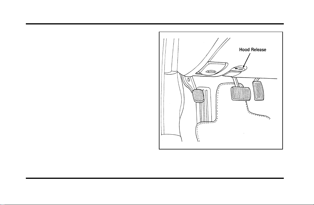
223
Opening the Hood
1. Inside the vehicle, pull the hood release handle
located under the bottom left corner of the
instrument panel.
The hood release under the instrument panel
File:11fnmcc.ex
Update:Fri Sep 6 08:51:16 1996
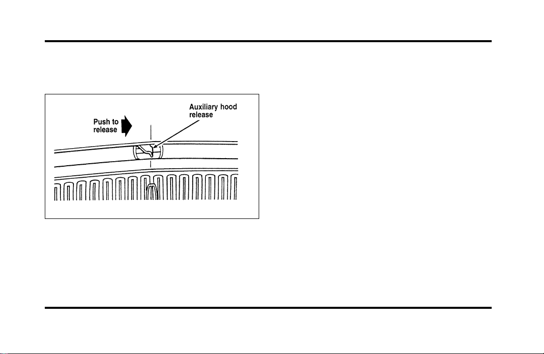
224
2. Go to the front of the vehicle and release the
auxiliary latch that is located under the hood at
the center of the vehicle.
The auxiliary latch under the front edge of the
hood
3. Lift the hood until the lift cylinders hold it
open.
Whenever you close the hood, latch it securely.
NOTE: Apply lubricant to the hood latch at
six-month intervals to maintain smooth and
trouble-free operation.
NOTE: Read and understand Precautions When
Servicing Your Vehicle at the beginning of this
chapter before opening the hood.
Engine Compartment
Your vehicle has a 4.6 liter 4V SFI engine. The
following page shows a diagram of where to find
items that you should regularly service.
File:11fnmcc.ex
Update:Fri Sep 6 08:51:16 1996
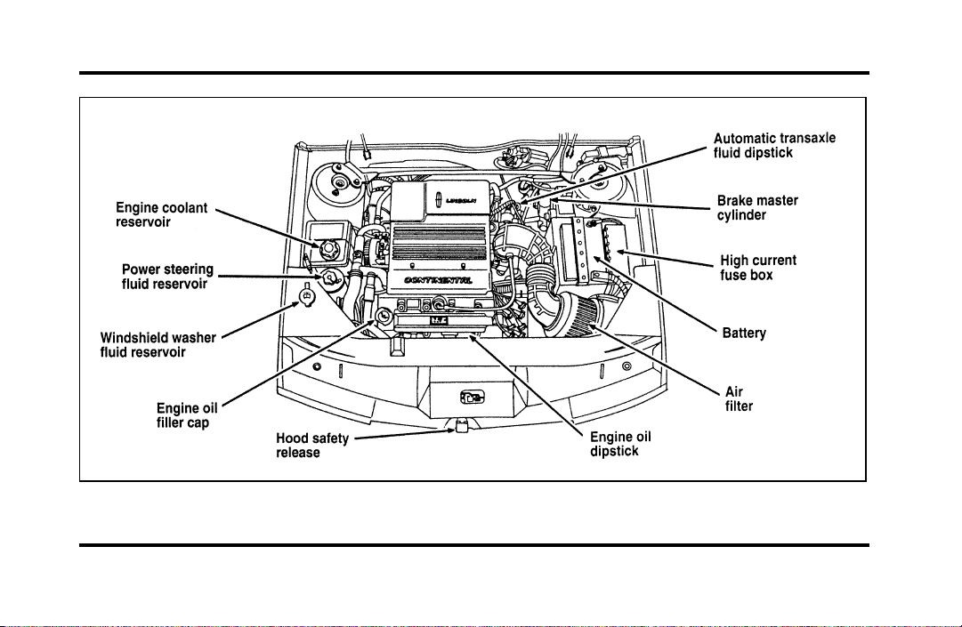
225
Engine compartment service points
File:11fnmcc.ex
Update:Fri Sep 6 08:51:16 1996
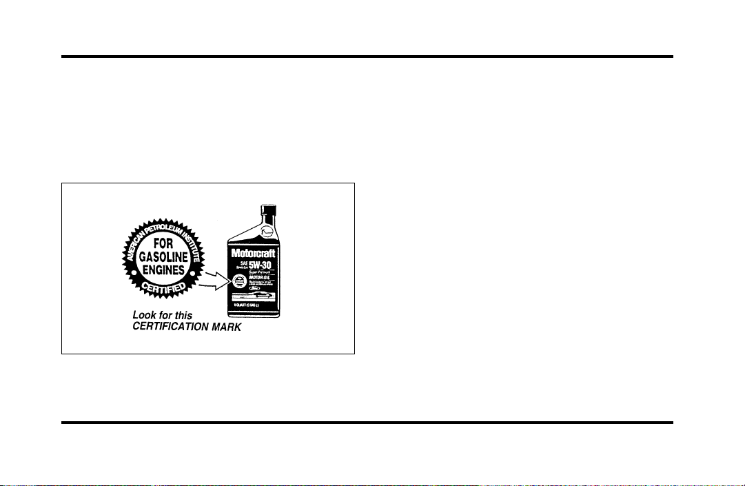
226
Engine Oil Recommendations
We recommend using Motorcraft oil or an
equivalent oil meeting Ford Specification
WSS-M2C153-F and displaying the American
Petroleum Institute CERTIFICATION MARK on the
front of the container.
The API Certification Mark
Never use:
❑
“Non-Detergent” oils
❑
Oils labeled API SA, SB, SC, SD, SE, SF or SG
❑
Additional engine oil additives, oil treatments or
engine treatments
Engine oils with an SAE 5W-30 viscosity are
PREFERRED for your vehicle. They provide the
best engine performance, fuel economy and engine
protection for all climates down to -15˚F (-25˚C).
Synthetic engine oils which are CERTIFIED and of
the preferred viscosity may be used in your engine.
The engine oil and oil filter must still be changed
according to the maintenance schedule.
File:11fnmcc.ex
Update:Fri Sep 6 08:51:16 1996
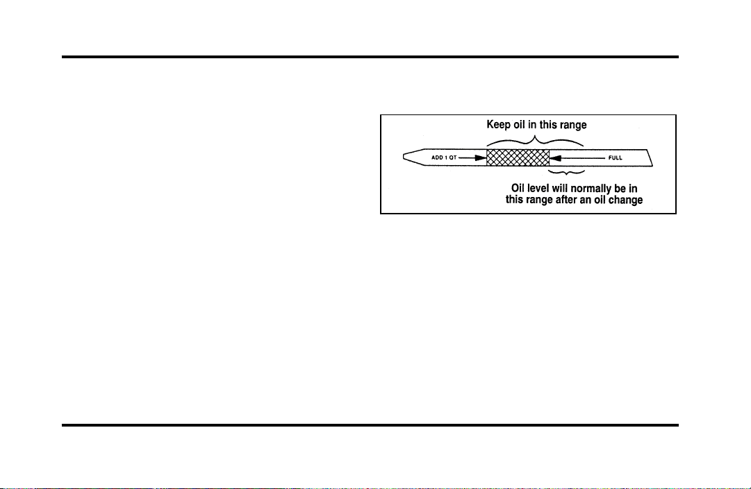
227
Checking and Adding Engine Oil
Since the proper amount of engine oil is important
for safe engine operation, check the oil using the
dipstick each time you put fuel in your vehicle.
Remember the engine must be off, the oil must be
warm and the vehicle must be parked on level
ground.
Checking the engine oil level:
1. Turn the engine off after it has warmed up and
allow a few minutes for the engine oil to drain
back into the oil pan.
2. Set the parking brake, making sure the gearshift
is securely latched in P (Park).
3. Open the hood. Protect yourself from engine
heat.
4. Locate the engine oil dipstick (highlighted in
yellow) and carefully pull it out of the engine.
5. Wipe the dipstick clean and put it back into
position, making sure it is fully seated.
Engine oil dipstick
6. Carefully pull the dipstick out again. If the oil
level is below the “ADD 1 QT” line, add
engine oil as necessary. If the oil level is
beyond the letter “F” in Full, engine damage or
high oil consumption may occur and some oil
must be removed from the engine.
7. Put the dipstick back in and make sure it is
fully seated.
File:11fnmcc.ex
Update:Fri Sep 6 08:51:16 1996

228
It may be necessary to add some oil between oil
changes. Make sure you use a CERTIFIED engine
oil of the preferred viscosity. Your vehicle’s
warranty coverage may not apply if engine damage
is caused by the use of improper engine oil.
Add engine oil through the oil filler cap highlighted
in yellow. To add oil, remove the filler cap and use
a funnel to pour oil into the opening. Be careful not
to overfill the engine. Recheck the oil level after 30
minutes to allow the oil to settle.
Changing the Engine Oil and the Oil
Filter
Change your engine oil and oil filter according to
these mileage and time requirements, whichever
occurs first.
Refer to the Maintenance Schedule booklet for
additional information.
File:11fnmcc.ex
Update:Fri Sep 6 08:51:16 1996
229
WARNING
ContinuouscontactwithUSEDmotor
oilhascausedcancerinlaboratory
mice.
Protectyourskinbywashingwithsoapandwater.
BrakeFluid
Undernormalcircumstances,yourvehicleshould
notuseupbrakefluidrapidly.However,expectthe
levelofthebrakefluidtoslowlyfallasyouput
moremileageonyourvehicleandthebrakelinings
wear.
Youshouldcheckthebrakefluidatevery
scheduledengineoilchange,butbesuretocheck
itatleastonceayear.Youcandothisbylooking
atthefluidlevelintheplasticreservoironthe
mastercylinder.(SeeTheEngineTypeinthis
chaptertolocatethemastercylinder.)Thefluid
levelshouldbebetweentheMAXandMINmark.
WARNING
Brakefluidistoxic.
Ifbrakefluidcontactseyes,flusheyeswithrunning
waterfor15minutes.Getmedicalattentionif
irritationpersists.Iftakeninternally,drinkwater
andinducevomiting.Getmedicalattention
immediately.
Ifthefluidislow,carefullycleanandremovethe
capfromthereservoir.Fillthereservoirtothe
MAXlinewithFordHighPerformanceDOT3
BrakeFluidC6AZ-19542-ABorequivalentDOT3
fluidmeetingFordspecificationESA-M6C25-A.
WARNING
Ifyouuseabrakefluidthatisnot
DOT3,youwillcausepermanent
damagetoyourbrakes.
DonotfillthereservoirabovetheMAXline.
File:11fnmcc.ex
Update:Fri Sep 6 08:51:16 1996
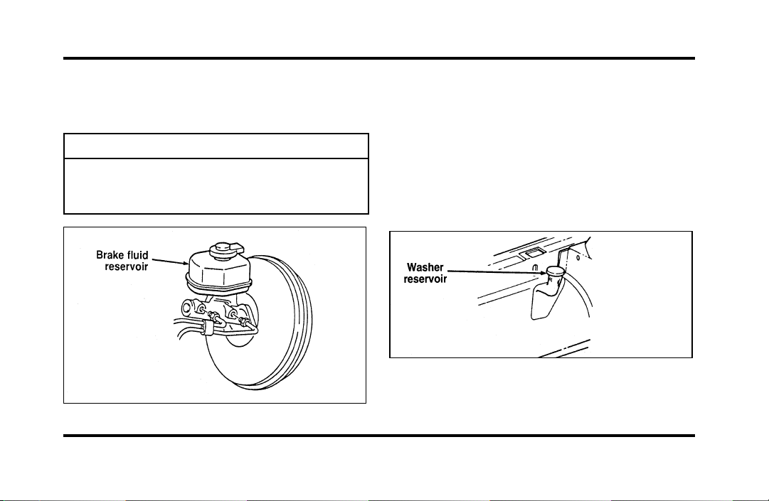
230
Ifyoufindthatthefluidlevelisexcessivelylow—
belowtheseamorridgeontheoutsideofthe
plasticreservoir—havethebrakesysteminspected.
WARNING
Donotletthereservoirforthemaster
cylinderrundry.Thismaycausethe
brakestofail.
Thebrakefluidreservoir
WindshieldWasherFluid
WasherFluid
Checkthelevelofthewindshieldwasherfluid
everytimeyoustopforfuel.Thereservoirfor
washerfluidislocatedonthepassenger’ssideof
theenginecompartment.Visualinspectioncan
determineifthewasherfluidisadequate.Donot
operatethewasherwhenthereservoirisempty.
Thereservoirforthewindshieldwasherfluid
File:11fnmcc.ex
Update:Fri Sep 6 08:51:16 1996
231
WARNING
Donotputwindshieldwasherfluidin
thecontainerfortheenginecoolant.
Usespeciallyformulatedwindshieldwasherfluid
ratherthanplainwater,becausespecially
formulatedwasherfluidscontainadditivesthat
dissolveroadgrime.Forsafetyreasons,washer
fluidscontaininganappropriateantifreezesuchas
methanolshouldbeusedinfreezingweather
(temperaturesbelow32˚F[0˚C]).Stateorlocal
regulationsonVolatileOrganicCompounds(VOCs)
mayrestrictuseofthemostcommonantifreeze,
methanol.Washerfluidscontainingnon-methanol
antifreezeagentsshouldbeusedonlyifthey
providecoldweatherprotectionwithoutdamaging
thevehicle’spaintfinish,wiperblades,and
windshieldwashersystem.
EngineCoolant
CheckingtheEngineCoolant
NOTE:Besuretoreadandunderstand
PrecautionsWhenServicingYourVehicleatthe
beginningofthischapter.
WARNING
Thecoolingfanisautomaticandmay
comeonatanytime.Alwaysdisconnect
thenegativeterminalofthebattery
beforeworkingnearthefan.
File:11fnmcc.ex
Update:Fri Sep 6 08:51:16 1996
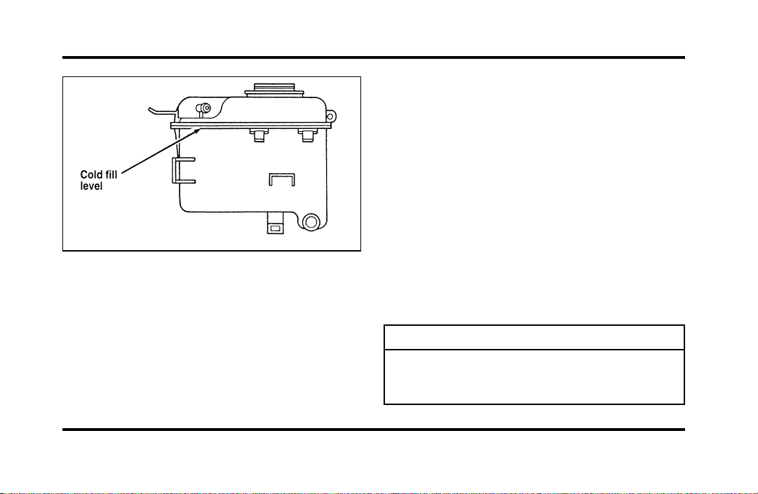
232
Theenginecoolantreservoir
Yourvehicle’scoolantprotectsyourenginefrom
overheatinginthesummerandfromfreezinginthe
winter.Checkthelevelofthecoolantatleastonce
amonth.Simplylookattheenginecoolant
reservoirlocatedintheenginecompartment.To
locatethereservoir,seethediagramofyour
vehicle’sengineunderEngineType,inthischapter.
Checktheenginecoolantlevelintheengine
coolantreservoiratleastonceamonthusingthe
followingguidelines.
Whenyourvehicle’sengineiscool,thecoolant
levelintheenginecoolantreservoirshouldbeat
thetopoftheclearportionofthereservoir.Ifthe
levelisbelowthecoldfilllevel,coolantmayneed
tobeadded.
Thecoolantadditivesalsoprotecttheentirecooling
systemfrominternalpassagewaycorrosionand
theseadditiveslubricatethewaterpump.The
coolantshouldbeservicedasnotedinthe
MaintenanceSchedulebooklet.
AddingEngineCoolant
WARNING
Donotputenginecoolantinthe
containerforthewindshieldwasher
fluid.
File:11fnmcc.ex
Update:Fri Sep 6 08:51:16 1996
233
Ifsprayedonthewindshield,enginecoolantcould
makeitdifficulttoseethroughthewindshield.
Whentheengineiscool,adda50/50mixtureof
enginecoolantandwatertotheenginecoolant
recoveryreservoir—DONOTADDDIRECTLYTO
THERADIATOR.Addstraightwateronlyinan
emergency,butyoushouldreplaceitwitha50/50
mixtureofcoolantanddistilledwaterassoonas
possible.
Checkthecoolantlevelinthecoolantrecovery
reservoirthenextfewtimesyoudrivethevehicle.
Ifnecessary,addenoughofa50/50mixtureof
coolantandwatertobringtheliquidleveltothe
filllineonthereservoir.
WARNING
Neverremovethecoolantrecoverycap
whiletheengineisrunningorhot.
Ifyoumustremovethecoolantrecoverycap,
followthesestepstoavoidpersonalinjury:
1. Beforeyouremovethecap,turntheengineoff
andletitcool.
2. Whentheengineiscool,wrapathickcloth
aroundthecap.Slowlyturncap
counterclockwisetothefirststop.
3. Stepbackwhilethepressurereleases.
4. Whenyouaresurethatallthepressurehas
beenreleased,usetheclothtopressthecap
down,turnitcounterclockwise,andremoveit.
UseFordPremiumCoolingSystemFluid
E2FZ-19549-AA(inCanada,MotorcraftCXC-8-B)or
anequivalentpremiumenginecoolantthatmeets
FordspecificationESE-M97B44-A.FordPremium
EngineCoolantisanoptimizedformulathatwill
protectallmetalsandrubberelastomersusedin
Fordcoolingsystemsfor4yearsor50,000miles
(80,000km).
File:11fnmcc.ex
Update:Fri Sep 6 08:51:16 1996

234
Do not use alcohol or methanol antifreeze or any
engine coolants mixed with alcohol or methanol
antifreeze. Do not use supplemental coolant
additives in your vehicle. These additives may harm
your engine cooling system. The use of an improper
coolant may void the warranty of your vehicle’s
engine cooling system.
Recycled engine coolant
Ford Motor Company recommends that Ford and
Lincoln-Mercury dealers use recycled engine coolant
produced by Ford-approved processes. Not all
coolant recycling processes produce coolant which
meets Ford specification ESE-M97B44-A, and use of
such coolant may harm engine and cooling system
components.
Always dispose of used automotive fluids in a
responsible manner. Follow your community’s
regulations and standards for recycling and disposing
of automotive fluids.
Coolant refill capacity
To find out how much fluid your vehicle’s cooling
system can hold, refer to Refill capacities in the
Capacities and specifications chapter.
Have your dealer check the engine cooling system
for leaks if you have to add more than a quart
(liter) of engine coolant per month.
Severe winter climate
If you drive in extremely cold climates (less than
-34˚F [-36˚C]), it may be necessary to increase the
coolant concentration above 50%. Refer to the chart
on the coolant container to ensure the coolant
concentration in your vehicle is such that the
coolant will not freeze at the temperature level in
which you drive during winter months. Never
increase the engine coolant concentration above
60%. Leave a 50/50 mixture of engine coolant and
water in your vehicle year-round in non-extreme
climates.
File:11fnmcc.ex
Update:Fri Sep 6 08:51:16 1996

235
Engine Coolant Refill Procedure
Proper procedures for a complete coolant drain and
flush of the cooling system can be found in the Car
Service Manual. Following these recommended
procedures will ensure that the specified coolant
level and a 50/50 or appropriate mixture of coolant
and water is maintained.
Engine Coolant Refill Procedure
When the entire cooling system is drained and
refilled, the following procedure should be used to
ensure a complete fill:
NOTE: It is imperative the following procedure be
adhered to. Failure to do so could result in damage
to your engine.
❑
Remove coolant reservoir pressure cap.
❑
Remove the engine coolant outlet tube fill plug
on the engine.
❑
With the engine off and cool, add a 50/50
mixture of recommended cooling system fluid
and water to the coolant outlet tube fill neck
until the reservoir is full.
NOTE: DO NOT FILL COOLANT SYSTEM
THROUGH COOLANT RESERVOIR. COOLANT
WILL NOT ENTER ENGINE, WHICH CAN LEAD
TO ENGINE DAMAGE.
NOTE: Avoid spilling coolant on the front end
accessory drive belt, as this will allow the belt to
slip and become noisy.
❑
Reinstall the pressure cap to the coolant
reservoir.
❑
Continue filling at the engine coolant tube fill
neck slowly while allowing air to escape.
❑
Reinstall the engine coolant tube fill plug when
the system is full.
File:11fnmcc.ex
Update:Fri Sep 6 08:51:16 1996

236
❑
Select maximum heater temperature and fan
speed settings. Position control to discharge air
at A/C vents in instrument panel.
❑
Start engine and allow to idle. While engine is
idling, feel for hot air at A/C vents.
NOTE: IF AIR DISCHARGE REMAINS COOL AND
ENGINE TEMPERATURE GAUGE DOES NOT
MOVE, SHUT ENGINE OFF IMMEDIATELY.
This is an indication of low coolant level and/or air
pockets in coolant system. Allow engine to cool and
repeat the previous steps.
❑
Allow to idle until normal operating temperature
is reached. Hot air should discharge from A/C
vents. The engine temperature gauge should
maintain a stabilized reading in the middle of
the “NORMAL” range and the lower radiator
hose should feel hot to the touch.
❑
Shut off the engine and allow to cool down.
❑
After the engine cools down, recheck the
engine coolant level. Fill reservoir to the
COLD-FULL level as required.
❑
Check for leaks at the draincock, block plug
and vent plug.
❑
Recheck the engine coolant level, using the
recommended procedure, after one or two
occasions of vehicle use. Fill to COLD-FULL
level as required.
File:11fnmcc.ex
Update:Fri Sep 6 08:51:16 1996

237
Power Steering Fluid
Check the level of the power steering fluid at least
twice a year (i.e., every Spring and Fall).
Checking and Adding Power Steering
Fluid
1. Start the engine and let it run until the power
steering fluid reaches normal operating
temperature. The power steering fluid will be at
the right temperature when the engine coolant
temperature gauge in the instrument cluster is
near the center of the NORMAL operating
temperature range.
2. While the engine idles, turn the steering wheel
back and forth several times. Make sure that
the cap assembly is installed at this time.
3. Turn the engine off and check the level on the
power steering reservoir.
4. The fluid level is viewed through the sight
window on the power steering reservoir. If the
power steering fluid is below the middle line,
add fluid in small amounts, continuously
checking the level. Do not overfill.
File:11fnmcc.ex
Update:Fri Sep 6 08:51:16 1996
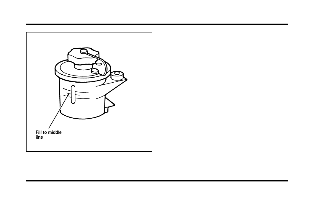
238
The power steering fluid reservoir
Use only MERCONH ATF power steering fluid.
If the power steering fluid is low, do not drive your
vehicle for a long period of time before adding fluid.
This can damage the power steering pump.
Automatic Transaxle Fluid
Under normal circumstances, you do not need to
check the fluid level of the transaxle, since your
vehicle does not use up transaxle fluid. Refer to the
Maintenance Schedule booklet for replacement
intervals. However, if the transaxle is not working
properly — for instance, the transaxle may slip or
shift slowly, or you may notice some sign of fluid
leakage — the fluid level should be checked.
NOTE: If the vehicle has been operated for an
extended period at high speeds or in city traffic
during hot weather, or pulling a trailer, the vehicle
should be turned off for about 30 minutes to allow
the fluid to cool before checking.
File:11fnmcc.ex
Update:Fri Sep 6 08:51:16 1996

239
Checking the Automatic Transaxle
Fluid
With the vehicle on a level surface and the brake
fully applied, start the engine and move the gear
shift selector through all of the gears allowing
sufficient time for each position to engage. Securely
latch the gear shift selector in the P (Park) position.
Fully set the parking brake and leave the engine
running.
Wipe off the dipstick cap and pull the dipstick out.
Wipe the indicator end clean. Put the dipstick back
into the filler tube and make sure it is fully seated.
Pull the dipstick out and read the fluid level.
NOTE: Your vehicle should not be driven until
some fluid has been added if the fluid level is
below the bottom dimple on the dipstick and the
outside temperature is above 50˚F (10˚C). Add only
enough fluid to bring the level above the bottom
hole.
If the vehicle has not been driven and the fluid
level is above the bottom dimple on the dipstick, do
not add fluid. Recheck the fluid level after your
vehicle has reached normal operating temperature.
Normal operating temperature is reached after
driving approximately 20 miles (30 km). The fluid
level should be within the crosshatched area on the
dipstick.
NOTE: If the vehicle has been operated for an
extended period at high speeds, driven in city traffic
during hot weather, or has been pulling a trailer,
the vehicle should be turned off for about 30
minutes to allow the fluid to cool before checking.
File:11fnmcc.ex
Update:Fri Sep 6 08:51:16 1996
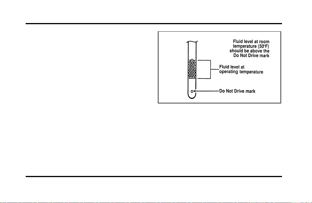
240
Adding Automatic Transaxle Fluid
Before adding any fluid, be sure that the correct
type will be used. Correct type is shown on the
dipstick.
Add fluid in 1/2 pint (.25L) increments through the
filler tube to bring the level to the correct area on
the dipstick. DO NOT OVERFILL. If the level is
above the top hole in the dipstick, excess fluid
should be removed by a qualified technician.
NOTE: Always dispose of used automotive fluids in
a responsible manner. Follow your community’s
standards for disposing of these types of fluids. Call
your local recycling center to find out about
recycling automotive fluids.
Automatic overdrive transaxle fluid dipstick
Battery
Your vehicle may have a Motorcraft
maintenance-free battery. When the original
equipment battery is replaced under warranty it
may be replaced by a low-maintenance battery. See
Motorcraft Parts at the end of this chapter for the
proper replacement battery.
File:11fnmcc.ex
Update:Fri Sep 6 08:51:16 1996
241
The low-maintenance battery has removable vent
caps for checking the electrolyte level and adding
water. The electrolyte level should be checked at
least every 24 months or 24,000 miles
(40,000 km) in temperatures up to 90˚F (32˚C)
and more often in temperatures above 90˚F (32˚C).
Keep the electrolyte level in each cell up to the
level indicator. Do not overfill.
If the level gets low, refill the battery with distilled
water. If necessary, you can add tap water to the
battery, provided the water is not hard or does not
have a high mineral or alkali content. If the battery
needs water quite often, have the charging system
checked for a possible malfunction.
Help Us Protect Our Environment
Ford Motor Company strongly recommends that
used lead-acid batteries be returned to an
authorized recycling facility for disposal.
Battery recycling symbol
Because your vehicle’s engine is electronically
controlled by a computer, some control conditions
are maintained by power from the battery. If you
ever disconnect the battery or install a new battery,
you must allow the computer to “relearn” its idle
conditions before your vehicle will drive properly.
To let the engine do this, put the gearshift in P
(Park), turn off all the accessories, and start the
vehicle. Let the engine idle for at least one minute.
(Engine must be warm in order to “learn.”) Also,
allow approximately 10 miles (16 km) of stop and
go traffic for your vehicle’s engine to completely
“relearn” its idle.
File:11fnmcc.ex
Update:Fri Sep 6 08:51:16 1996

242
If you do not let the engine relearn its idle, the idle
quality of your vehicle may be adversely affected
until the idle is relearned. Your vehicle will
eventually relearn its idle while you drive it, but it
takes much longer than if you use the previous
procedure.
Passenger Compartment Air Filter
Using a screwdriver,
1. Remove the two screws retaining the passenger
side half of the cowl vent screen.
2. From inside the vehicle, pull the hood release.
3. Open the hood, then pull the hood pad away
from the cowl vent screen.
4. Remove the cowl vent screen, then the filter.
Reverse procedure to install. The filter must be
properly positioned in the housing for proper
installation.
Wiper Blades
Check the windshield wiper blades at least twice a
year. Also check them whenever they seem less
effective than usual. Substances such as tree sap
and some hot wax treatments used by commercial
car washes reduce the effectiveness of wiper blades.
If the blades do not wipe properly, clean both the
windshield and the wiper blades. Use undiluted
windshield washer solution or a mild detergent.
Rinse thoroughly with clear water. Do not use fuel,
kerosene, paint thinner, or other solvents to clean
your wiper blades. These will damage your blades.
To make reaching the wiper blades easy, simply
turn the ignition to the ACC position and turn your
wipers on. Wait for them to reach a vertical
position and turn the ignition to the OFF position.
Do not move the wipers manually. Manually
moving the wipers across the windshield may
damage them.
File:11fnmcc.ex
Update:Fri Sep 6 08:51:16 1996
243
Wiperbladereplacement
Ifthewiperbladesstilldonotworkproperlyafter
youcleanthem,youmayneedtoreplacethewiper
bladeassemblyorthebladeelement.When
replacingthewiperbladeassembly,bladerefill,or
wiperarmalwaysuseaMotorcraftpartor
equivalent.Toreplacetheblades,followthe
instructionsthatcomewiththem.
SecuriTire(Ifequipped)
SecuriTiresaredesignedtoallowyoutocontinue
drivingyourContinentalalimitednumberofmiles
whenoneofyourvehicle’stiresisatloworeven
zeroairpressure.
Atzeropressure,theSecuritireswillprovideyou
withaminimumdrivingcapabilityofapproximately
20miles(30kms).Howyoudriveandtheactual
amountofairpressureleftinyourtireswill
determineexactlyhowmanymilescanbedriven.
Toextendthemileageandhelppreventdamageto
lowordeflatedtires,youshould:
❑
notexceed55mph(90km/h)anddriveata
reducedrateofspeed,ifpossible
❑
avoidexcessivehardsteeringandbraking
maneuvers,ifpossible
❑
stopperiodicallytoallowthetirestocooldown
WARNING
Ifyourvehicleisdrivenwithalow
tire,thetireitselfmaybecomeveryhot.
Allowthetireandwheeltocoolbefore
attemptingtochangeit.
File:11fnmcc.ex
Update:Fri Sep 6 08:51:16 1996
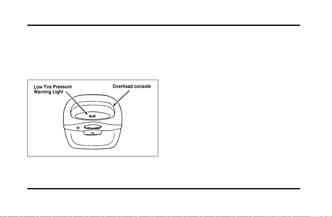
244
Pressure Alert System
Each of your SecuriTires is monitored by a low tire
pressure sensor. A warning will appear in the
overhead console when the pressure in one of your
tires drops below acceptable levels or if the system
has malfunctioned.
The Low Tire Pressure warning in the
overhead console
THIS DEVICE COMPLIES WITH FCC RULES,
PART 15. OPERATION IS SUBJECT TO THE
FOLLOWING TWO CONDITIONS: (1) THIS
DEVICE MAY NOT CAUSE HARMFUL
INTEREFERENCE AND (2) THIS DEVICE MUST
ACCEPT ANY INTEREFERENCE THAT MAY BE
RECEIVED, INCLUDING INTEREFERENCE THAT
MAY CAUSE UNDESIRABLE OPERATION.
Maintenance Warning
The “Low Tire Pressure” warning will illuminate
and stay on when one of your vehicle’s tires drops
below 18 psi (124 kps). The warning light will also
come on and stay lit if the Pressure Alert System
has malfunctioned.
If this warning appears, check the pressure in your
tires at the earliest possible convenience and adjust
any tire that is low to the recommended air
pressure level. This information can be found on
the Service Station Information page at the back of
this manual or on the driver’s door placard.
File:11fnmcc.ex
Update:Fri Sep 6 08:51:16 1996
245
Ifthewarningremainsonafteryouhaveadjusted
thetirestorecommendedairpressurelevels,take
yourvehicletoanauthorizedLincoln/Mercury
dealerforservice.
FlatTireWarning
Ifthesensorsdetectatirepressurelowerthan10
psi(68kps),the“LowTirePressure”warningwill
flashrepeatedlyintheoverheadconsoleandthe
message“WarningLowTirePressure”willbe
displayedintheMessageCenter,indicatingan
impendingflattire.Ifthisconditionoccurs,your
SecuriTirerequiresserviceassoonaspossible.Refer
toServicingYourSecuriTires.
NOTE:ThePressureAlertSystemwillactivateonly
whenthevehicleismovingfasterthan10mph
(15km/h).
ServicingYourSecuriTires
WARNING
Donotuseaerosoltireinflator/sealer
withSecuritires.Doingsomaydamage
thetire’spressuresensor.
IfyoucannotserviceyourSecuriTireimmediately,
replaceitwithyourmini-spareassoonasitissafe
todoso.
Yourmini-sparetirecanbeuseduntilyour
SecuriTirehasbeenrepaired.SeeTiresinthe
Servicingchapterofthisguideformoreinformation
onusingthespare.
File:11fnmcc.ex
Update:Fri Sep 6 08:51:16 1996
246
Itisrecommendedthatyoualwayshaveyour
SecuriTiresservicedbyanauthorizedMichelintire
dealer.EachSecuriTireisequippedwitha
pressuresensoraroundthewheelrim.This
sensorcouldbedamagedwhenremovingand
installingthetire.ServicingaSecuriTireat
locationsotherthanyourMichelintiredealermay
adverselyaffectyourwarranty.
IfyouhavequestionsconcerningyourSecuriTires
orservicing,pleasecalltheMichelinTire
InformationLineat1-800-847-3435orcontactyour
localMichelintiredealer.
Tires
❑
Useanaccuratetirepressuregauge.
❑
Checkthetirepressurewhentiresarecold,
afterthevehiclehasbeenparkedforatleast
onehourorhasbeendrivenlessthan3miles
(5km).
❑
Adjusttirepressuretorecommended
specificationsfoundontheSafetyCompliance
CertificationLabel.
WARNING
Improperlyinflatedtirescanaffect
vehiclehandlingandcanfailsuddenly,
possiblyresultinginlossofvehicle
control.
Intheeventofcontinuousoperationathighspeed,
thecoldairpressureinalltiresmustbeincreased
by4p.s.i.(28kpa)whencomparedtotheinflation
pressureshownonthetiredecalpostedinthe
glovecompartment.Undernocircumstancesshould
youexceedmaximumtireinflationpressurewhich
ismoldedonthetireoutersidewall.
File:11fnmcc.ex
Update:Fri Sep 6 08:51:16 1996

247
Tire Rotation
Because your vehicle’s front and rear tires perform
different jobs, they often wear differently. To make
sure your tires wear evenly and last longer, rotate
them as indicated in the following diagram.
Do not include the spare tire as part of your
rotation.
For tire rotation intervals, see the Maintenance
Schedule booklet. If you notice that the tires wear
unevenly, have them checked.
Rotating the tires
File:11fnmcc.ex
Update:Fri Sep 6 08:51:16 1996
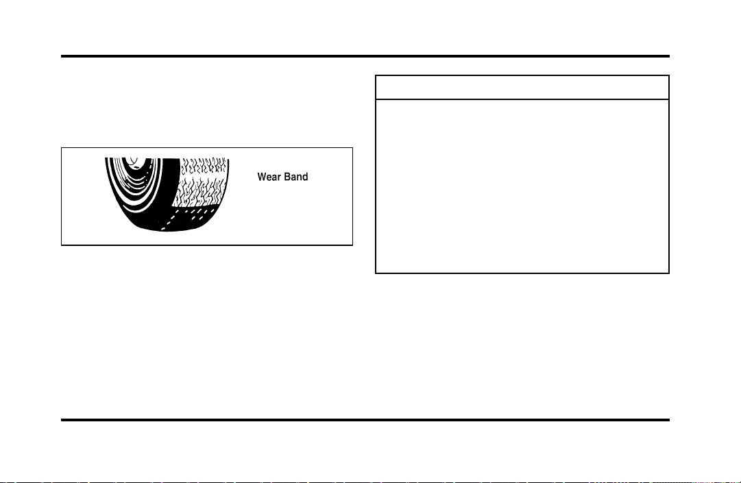
248
ReplacingtheTires
Replaceanytiresthatshowwearbands.Whenyour
tireshowsawearband,ithasonly1/16inch(2
mm)oftreadleft.
Aworn-outtire
Becauseyourvehicle’stiresmaywearunevenly,
youmayneedtoreplacethembeforeawearband
appearsacrosstheentiretread.
WARNING
Whenreplacingfullsizetires,never
mixradial,bias-belted,orbias-type
tires.Useonlythetiresizesthatare
listedonthetirepressuredecal.Make
surethatalltiresarethesamesize,
speedrating,andload-carryingcapacity.
Useonlythetirecombinations
recommendedonthedecal.Ifyoudo
notfollowtheseprecautions,your
vehiclemaynotdriveproperlyand
safely.
Tiresthatarelargerorsmallerthanyourvehicle’s
originaltiresmayalsoaffecttheaccuracyofyour
speedometer.
File:11fnmcc.ex
Update:Fri Sep 6 08:51:16 1996

249
Information About Tire Quality Grades
New vehicles are fitted with tires that have their
Tire Quality Grade (described below) molded into
the tire’s sidewall. These Tire Quality Grades are
determined by standards that the United States
Department of Transportation has set.
Tire Quality Grades apply to new pneumatic tires
for use on passenger cars. They do not apply to
deep tread, winter-type snow tires, space-saver or
temporary use spare tires, tires with nominal rim
diameters of 10 to 12 inches or limited production
tires as defined in Title 49 Code of Federal
Regulations Part 575.104(c)(2).
U.S. Department of Transportation — Tire
quality grades: The U.S. Department of
Transportation requires Ford to give you the
following information about tire grades exactly as
the government has written it.
Treadwear
The treadwear grade is a comparative rating based
on the wear rate of the tire when tested under
controlled conditions on a specified government test
course. For example, a tire graded 150 would wear
one and one-half (1 1/2) times as well on the
government course as a tire graded 100. The
relative performance of tires depends upon the
actual conditions of their use, however, and may
depart significantly from the norm due to variations
in driving habits, service practices and differences in
road characteristics and climate.
Traction A B C
The traction grades, from highest to lowest, are A,
B, and C, and they represent the tire’s ability to
stop on wet pavement as measured under controlled
conditions on specified government test surfaces of
asphalt and concrete. A tire marked C may have
poor traction performance.
File:11fnmcc.ex
Update:Fri Sep 6 08:51:16 1996
250
WARNING
Thetractiongradeassignedtothistire
isbasedonbraking(straightahead)
tractiontestsanddoesnotinclude
cornering(turning)traction.
TemperatureABC
ThetemperaturegradesareA(thehighest),B,and
C,representingthetire’sresistancetothe
generationofheatanditsabilitytodissipateheat
whentestedundercontrolledconditionsona
specifiedindoorlaboratorytestwheel.Sustained
hightemperaturecancausethematerialofthetire
todegenerateandreducetirelife,andexcessive
temperaturecanleadtosuddentirefailure.The
gradeCcorrespondstoalevelofperformance
whichallpassengercartiresmustmeetunderthe
FederalMotorVehicleSafetyStandardNo.109.
GradesBandArepresenthigherlevelsof
performanceonthelaboratorytestwheelthanthe
minimumrequiredbylaw.
WARNING
Thetemperaturegradeforthistireis
establishedforatirethatisproperly
inflatedandnotoverloaded.Excessive
speed,underinflation,orexcessive
loading,eitherseparatelyorin
combination,cancauseheatbuildup
andpossibletirefailure.
Snowtires
WARNING
Drivingtoofastforconditionscreates
thepossibilityoflossofvehiclecontrol.
Drivingatveryhighspeedsfor
extendedperiodsoftimemayresultin
damagetovehiclecomponents.
Useoftirechainsisnotrecommended.Theuseof
tirechainscouldresultindamagetoyourvehicle.
File:11fnmcc.ex
Update:Fri Sep 6 08:51:16 1996
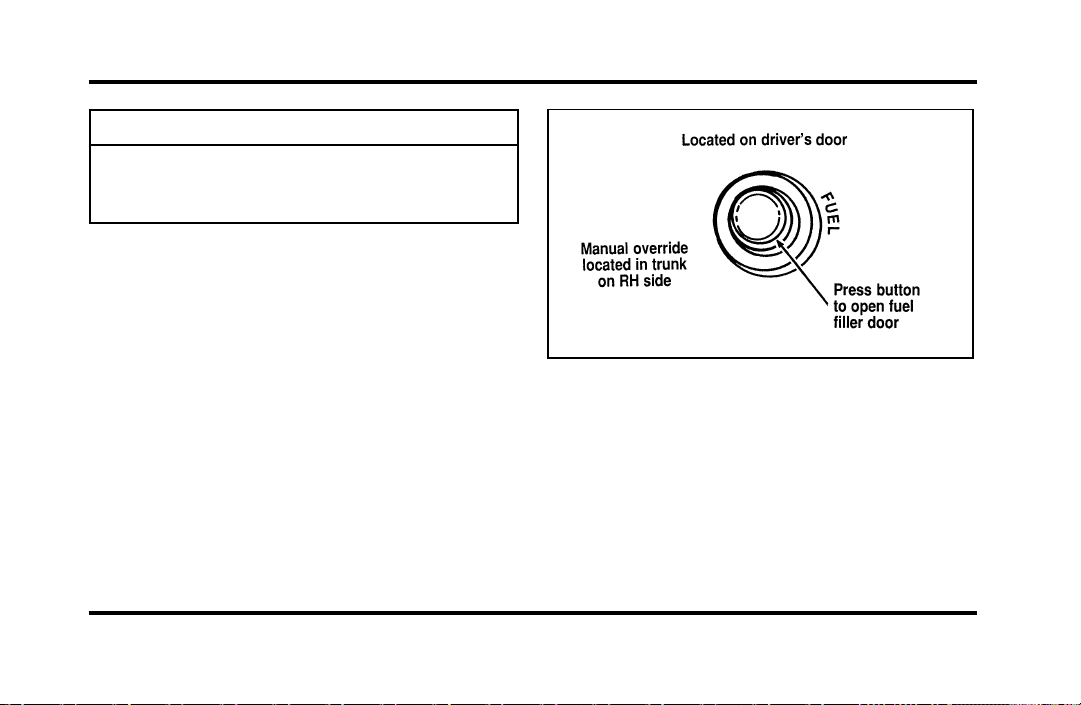
251
WARNING
Snowtiresmustbethesamesizeand
gradeasthetiresyoucurrentlyhaveon
yourvehicle.
FillingtheFuelTank
Thefuelfillerdoorcannotbeopenedfromoutside
thevehicle.Tounlatchthefueldoor,pushonthe
fueldoorbuttonlocatedonthedriversidedoor
trim.
Thefueldoorisontheexteriorofpassengerside,
nearthebackofthevehicle.ThewordsFUELFILL
andanarrowontheinstrumentclusterremindyou
thatthefueldoorisonthatside.
Thefueldoorreleasebutton
Ifthefueldoordoesnotopenwhenyoupushthe
releasebutton,openthetrunkandfindtheoverride
releaseontherightside.Theoverridereleaseisa
handlewhichsaysFUELFILLERDOORRELEASE
MANUALOVERRIDE.Openthefueldoorby
pullingonthehandle.
File:11fnmcc.ex
Update:Fri Sep 6 08:51:16 1996
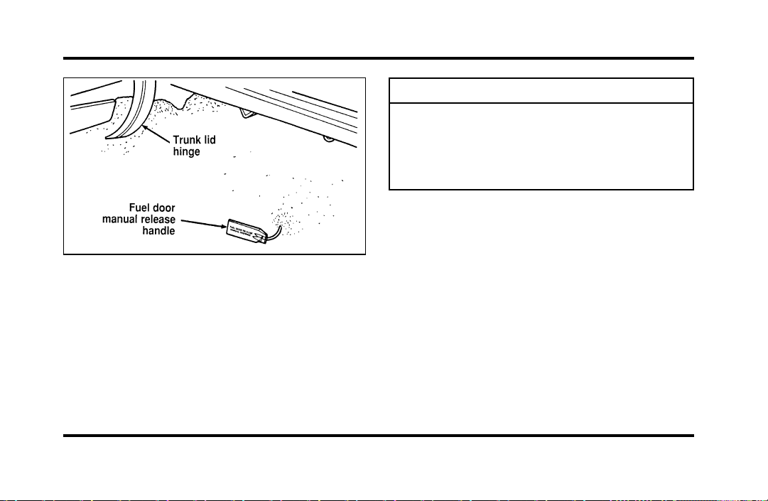
252
Fueldoorrelease—manualoverride
1. Afteropeningthefuelfillerdoor,removethe
capcarefullyandslowlybyturningit
counterclockwise1/2to3/4turn.Ifahissing
soundisheard,waituntilitstops,then
continueturninguntilthecapisfree.
WARNING
Thefuelsystemmaybeunderpressure.
Ifthefuelcapisventingvapororif
youhearahissingsound,waituntilit
stopsbeforecompletelyremovingthe
cap.
2. Makesurethatyoupumppremiumunleaded
fuelandputthenozzleallthewayinsidethe
fuelfillerpipe.
NOTE:Ifyouspillanyfuelonthebodyofyour
vehicle,cleanitoffimmediately.Thefuelmaydull
orsoftenthepaintifyoudonotwashitoff.
3. Replacethefuelcapcompletelywhenyouare
finished.Turnitclockwise1/4turnuntilitis
tight.Itwillclickwhenitisfullytightened.
4. Pushthefueldoorclosed.
File:11fnmcc.ex
Update:Fri Sep 6 08:51:16 1996

253
WARNING
Ifyoudonotusetheproperfuelcap,
thepressureinthefueltankcan
damagethefuelsystemorcauseitto
workimproperlyinacollision.
NOTE:Ifyoureplaceyourfuelcapwithan
aftermarketfuelfillercap,thecustomerwarranty
maybevoidforanydamagetothefueltank
and/orfuelsystem.
ChoosingtheRightFuel
UseonlyUNLEADEDFUEL.Theuseofleadedfuel
isprohibitedbylawandcoulddamageyourvehicle.
Yourvehiclewasnotdesignedtousefuel
containingmanganese-basedadditivessuchasMMT.
Additionally,vehiclescertifiedtoCaliforniaemission
standards(indicatedontheunderhoodVehicle
EmissionsControlInformationlabel)aredesignedto
operateonCaliforniareformulatedgasolines.If
Californiareformulatedgasolineisnotavailable
whenyourefuel,yourvehiclecanbeoperatedon
non-Californiafuels.However,eventhoughyour
enginewillperformadequatelyonothergasolines,
theperformanceoftheemissioncontroldevicesand
systemsmaybeadverselyaffected.Repairofdamage
causedbyusingafuelthatyourvehiclewasnot
designedformaynotbecoveredbyyourwarranty.
Octanerecommendation
Yourvehicleisdesignedtousepremiumgasoline
foroptimumperformancewithan(R+M)/2octane
ratingof91orhigher.Gasolineswithloweroctane
ratingscanbeused,butperformanceandfuel
economymaydecrease.Wedonotrecommend
gasolineslabeledas“premium”inhighaltitude
areasthataresoldwithoctaneratingslessthan91.
File:11fnmcc.ex
Update:Fri Sep 6 08:51:16 1996
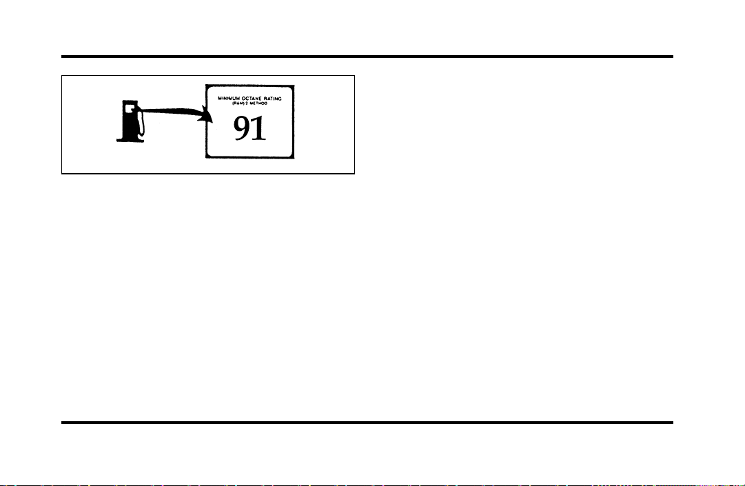
254
Typical octane rating label
Do not be concerned if your vehicle sometimes
knocks lightly. However, if it knocks heavily under
most driving conditions on the recommended
octane fuel, see your dealer or a qualified service
technician to prevent any engine damage.
Fuel quality
If you are experiencing starting, rough idle or
hesitation problems try a different brand of fuel. If
the condition persists, see your dealer or a qualified
service technician.
The American Automobile Manufacturers
Association (AAMA) issued a gasoline specification
to provide information on high quality fuels that
optimize the performance of your vehicle. We
recommend the use of gasolines that meet the
AAMA specification if they are available.
It should not be necessary to add any aftermarket
products to your fuel tank if you continue to use a
high-quality fuel.
Cleaner air
Ford approves the use of gasolines to improve air
quality, including reformulated gasolines that contain
oxygenates such as a maximum of 10% ethanol or
15% MTBE. There should be no more than 5%
methanol with cosolvents and additives to protect
the fuel system.
File:11fnmcc.ex
Update:Fri Sep 6 08:51:16 1996
255
SafetyInformationRelatingto
AutomotiveFuels
WARNING
Automotivefuelscancauseserious
injuryordeathifmisusedor
mishandled.
❑
Turnvehicleoffwhenrefueling.
❑
Donotsmokewhenrefueling.Fuelsare
extremelyflammable.
❑
Donotsiphonanyfuelbymouth.
WARNING
Gasolineorgasolineblendedwith
methanolcancauseblindnessand
possibledeathwhenswallowed.Ifany
fuelisswallowed,callaphysicianor
poisoncontrolcenterimmediately.
❑
Avoidbreathingvaporswhilerefueling.
❑
Iffuelissplashedontheskin,washwithsoap
andwater.
❑
Iffuelissplashedintheeyes,removecontact
lenses(ifworn),flushwithwaterfor15
minutes,andseekmedicalattention.
Gasolineandgasolineblendsmaycontainsmall
amountsofcarcinogens,suchasbenzene.Long-term
exposuretounleadedgasolinevaporshascaused
cancerinlaboratoryanimals.
Ifyouaretakingthemedication“Antabuse”or
otherformsofdisulfiramforthetreatmentof
alcoholism,vapororskincontactwitha
gasoline-methanolblend,maycausethesamekind
ofadversereactionasdrinkinganalcoholic
beverage.Insensitiveindividuals,seriouspersonal
injuryorsicknesscouldresult.Consultaphysician
promptlyifyouexperienceanadversereaction.
File:11fnmcc.ex
Update:Fri Sep 6 08:51:16 1996
256
RunningOutofFuel
NOTE:Avoidrunningoutoffuelbecausethis
situationmayhaveanadverseeffectonmodern
powertraincomponents.
Youmayneedtocranktheengineseveraltimes
beforethefuelsystemstartstopumpfuelfromthe
tanktotheengine.
Iftheenginedoesnotstart,checkthefuelpump
shut-offswitchandresetasrequired.SeeFuel
pumpshut-offswitchintheIndex.
WARNING
Neverpourfuelinthethrottlebodyor
attempttostarttheenginewiththeair
cleanerremoved.Doingsocouldresult
infireandpersonalinjury.
FuelEconomy
Fueleconomyisanestimateoftheefficiencyof
yourvehicleandcanbecalculatedasMilesPer
Gallon(MPG)orLitersPer100Kilometers
(L/100K).
Donotcalculatefueleconomyduringyourvehicle’s
break-inperiod.Thiswouldnotbeanaccurate
estimateofhowmuchfuelyourvehiclewill
normallyuse.
Tocalculatefueleconomy:
1. Fillthetankcompletelyandrecordtheinitial
odometerreading.
2. Everytimeyoubuyfuelrecordtheamount(in
gallonsorliters)purchased.
3. Afteratleastthreetofivetankfuls,fillthefuel
tankandrecordthefinalodometerreading.
4. Usetheseequationstocalculateyourfuel
economy.
File:11fnmcc.ex
Update:Fri Sep 6 08:51:16 1996

257
❑
English: MPG = (total miles)/(gallons used).
❑
Metric: L/100K = (liters used) x 100/(total
kilometers)
Comparisons With Environmental
Protection Agency (EPA) and Transport
Canada (TC) Fuel Economy Estimates
EPA fuel economy figures are obtained from
laboratory tests under simulated road conditions and
may not reflect the actual conditions you experience
or your style of driving. The EPA fuel economy
estimate is not a guarantee that you will achieve
the fuel economy shown.
The following decrease fuel economy:
❑
Lack of regular, scheduled maintenance
❑
Rapid acceleration and excessive speed
❑
Driving with your foot on the brake
❑
Sudden stops
❑
Extended engine idling
❑
Using speed control in hilly terrain
❑
Extended use of the A/C, defroster, rear
window defroster and other accessories
❑
Underinflated tires
❑
Heavy loads
❑
Aftermarket add-ons such as bike, ski or luggage
racks, bug deflectors, etc.
Self-Service Pointers
If you choose to do your own fueling, you should
also perform a few simple maintenance routines.
This extra effort will save you additional money and
contribute to the driving efficiency of your vehicle.
File:11fnmcc.ex
Update:Fri Sep 6 08:51:16 1996
258
Thefollowingproceduresrequireonlyatiregauge,
arag,anoilcanspoutandwindshieldwasherfluid.
❑
Checktheengineoilateveryrefuelingstop
❑
Cleanthewindshield,outsidemirrorsand
headlights
❑
Checkwindshieldwasherfluid
❑
Checktiresforexcessivewearorwornedges
❑
Checkthetirepressureatleastmonthly
EmissionControlSystem
Yourvehicleisequippedwiththree(3)catalytic
converterswhichareusedtoenableyourvehicleto
complywithapplicableexhaustemissions
requirements.
WARNING
Exhaustleaksmayresultintheentryof
harmfulandpotentiallylethalfumes
intothepassengercompartment.Under
extremeconditionsexcessiveexhaust
temperaturescoulddamagethefuel
system,theinteriorfloorcovering,or
othervehiclecomponents,possibly
causingafire.
Tomakesurethatthecatalyticconvertersandthe
otheremissionscontrolpartscontinuetowork
properly:
❑
Useonlypremiumunleadedfuel.
❑
Avoidrunningoutoffuel.
❑
Donotturnofftheignitionwhileyourvehicle
ismoving,especiallyathighspeeds.
❑
Donotpushstartyourvehicle.
File:11fnmcc.ex
Update:Fri Sep 6 08:51:16 1996
259
❑
HavetheserviceslistedintheMaintenance
Schedulebookletperformedaccordingtothe
specifiedschedule.Thescheduledmaintenance
servicesarerequiredbecausetheyare
consideredessentialtothelifeandperformance
ofyourvehicleandtoitsemissionssystem.
Ingeneral,maintenance,replacement,orserviceof
theemissionscontroldevicesorsystemsinyour
newFordMotorCompanyvehicleorenginemay
beperformedatyourexpensebyanyautomotive
repairestablishmentorindividualusingautomotive
partsequivalenttothosewhichyourvehicleor
enginewasoriginallyequipped.
FordstronglyrecommendstheuseofgenuineFord
replacementparts.IfotherthanFordorMotorcraft
partsorFordauthorizedremanufacturedpartsare
usedformaintenancereplacementsorforthe
serviceofcomponentsaffectingemissioncontrol,
suchnon-Fordpartsshouldbeequivalenttogenuine
FordMotorCompanypartsinperformanceand
durability.Itistheowner’sresponsibilityto
determinetheequivalencyofsuchparts.Please
consultyourwarrantybookletforcomplete
warrantyinformation.
WARNING
Donotpark,idle,ordriveyourvehicle
indrygrassorotherdrygroundcover.
Theemissionsystemheatsupthe
enginecompartmentandexhaust
system,whichcanstartafire.
Watchforfluidleaks,strangeodors,smoke,lossof
oilpressure,thechargewarninglight,thecheck
enginelight,orthetemperaturewarninglight.
Thesesometimesindicatethattheemissionsystem
isnotworkingproperly.
File:11fnmcc.ex
Update:Fri Sep 6 08:51:16 1996

260
Do not make any unauthorized changes to your
vehicle or engine. Changes that cause more
unburned fuel to reach the exhaust system can
increase the temperature of the engine or exhaust
system.
By law, anyone who manufactures, repairs, services,
sells, leases, trades vehicles, or supervises a fleet of
vehicles is not permitted to intentionally remove an
emission control device or prevent it from working.
In some of the United States and in Canada,
vehicle owners may be liable if their emission
control device is removed or is prevented from
working.
Do not drive your vehicle if it does not operate
properly. See your dealer if the engine runs on for
more than five seconds after you shut it off or if it
misfires, surges, stalls, or backfires.
Information about your vehicle’s emission control
system is on the Vehicle Emission Control
Information decal located on or near the engine.
This decal identifies engine displacement and gives
some tune-up specifications.
How to Prepare Your Vehicle for
Inspection/Maintenance (I/M) Testing
In some localities it may become a legal
requirement to pass an Inspection/Maintenance
(I/M) test of the On-Board Diagnostic (OBD) II
system. If the vehicle’s powertrain system or its
battery has just been serviced, the OBD II system is
reset to a not ready for I/M testing condition. To
prepare for I/M testing, the law specifies that
additional mixed city and highway driving is
required to complete the check of the OBD II
system.
File:11fnmcc.ex
Update:Fri Sep 6 08:51:16 1996

261
The driving modes required to reach the ready
condition consist of a minimum of 30 minutes of
city and highway driving as described below:
❑
At least twenty minutes driving in stop and go,
city type traffic with at least four idle periods.
❑
At least ten minutes of driving on an
expressway or highway.
Before completing the above driving modes, the
engine must be warmed up and at operating
temperature. Once started, the vehicle must not be
turned off during these driving modes.
Lights and Bulb Replacement
It is a good idea to check the operation of the
following lights frequently:
❑
headlamps
❑
high-mount brakelamp
❑
tail lamps
❑
brakelamps
❑
hazard flasher
❑
turn signals
❑
side markers
❑
license plate lamps
The alignment of your headlamps should be
checked if:
❑
oncoming motorists frequently signal you to turn
off your vehicle’s high beams when you do not
have the high beams on
❑
the headlamps do not seem to give you enough
light to see clearly at night
❑
the headlamp beams are pointed substantially
away from a position slightly down and to the
right
File:11fnmcc.ex
Update:Fri Sep 6 08:51:16 1996
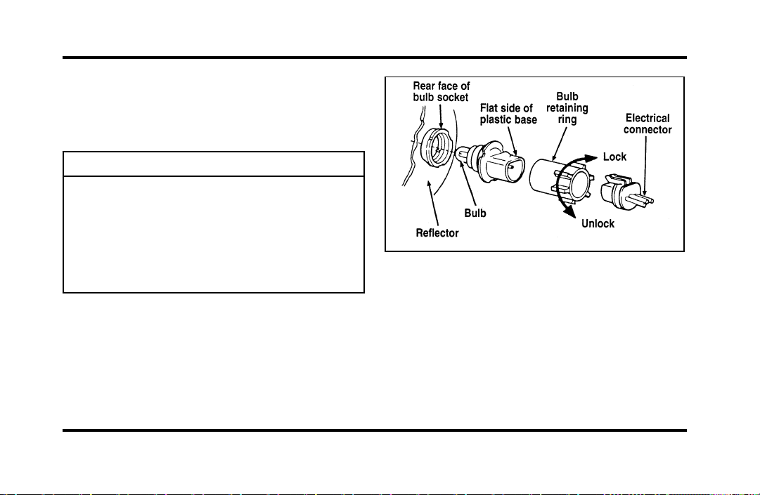
262
HeadlampBulb
Theheadlampsonyourvehicleusereplaceable
bulbs.Whenthelampburnsout,simplyreplacethe
bulb,ratherthanthewholelamp.
WARNING
Handleahalogenheadlampbulb
carefullyandkeepoutofchildren’s
reach.Graspthebulbonlybyitsplastic
baseanddonottouchtheglass.Theoil
fromyourhandcouldcausethebulbto
breakthenexttimetheheadlampsare
operated.
Donotremovetheburned-outbulbunlessyoucan
immediatelyreplaceitwithanewone.Ifabulbis
removedforanextendedperiodoftime,
contaminantsmayentertheheadlamphousingand
affectitsperformance.
Partsofaheadlamp
Removingtheheadlampbulb
1. Makesurethattheheadlampswitchisinthe
OFFposition.
2. Liftthehoodandremovetheplasticsight
shieldcoveringthebackoftheheadlampsby
liftingupontherearcornerstoreleasethe
velcroattachments.Lifttheshieldandpull
towardsthewindshield.
File:11fnmcc.ex
Update:Fri Sep 6 08:51:16 1996

263
3. At the back of the headlamp, pull back and up
slightly on the two right angle brackets to
release the headlamp assembly from the
vehicle.
4. Carefully pull the headlamp assembly away
from the vehicle to expose the back of the bulb
and wiring connector.
5. Remove the electrical connector from the bulb
by grasping the wire with a quick pull
rearward.
6. Remove the retaining ring by turning it 1/8 of
a turn to free it from the socket. Then slide the
ring off the plastic base of the bad bulb. Keep
the ring. You must use it again to hold the
new bulb in place.
7. Carefully remove the bulb assembly from its
socket by gently pulling it rearward without
turning.
Installing the headlamp bulb
1. With the flat side of the bulb’s plastic base
facing upward, insert the glass end of the bulb
into the socket. You may need to turn the bulb
left or right to line up the grooves in the plastic
base with the tabs in the socket. When the
grooves are aligned, push the bulb into the
socket until the plastic base contacts the rear of
the socket.
2. Slip the bulb retaining ring over the plastic base
until it contacts the rear of the socket. Lock
the ring into the socket by rotating it clockwise
until you feel a “stop.”
3. Push the electrical connector into the rear of
the plastic base until it snaps, locking it into
position.
4. Carefully position the headlamp assembly onto
the vehicle making sure the alignment pins are
inserted into the proper holes.
File:11fnmcc.ex
Update:Fri Sep 6 08:51:16 1996

264
5. Hold the headlamp assembly snugly against the
vehicle and push down on the right angle
brackets to lock the lamp into position.
6. Install the plastic sight shield.
7. Turn the headlamps on and make sure that
they work properly. If the headlamp was
correctly aligned before you changed the bulb,
you should not need to align it again.
Aiming Headlamps
Your vehicle is equipped with a Vehicle Headlamp
Aim Device (VHAD) on each headlamp body. Each
headlamp may be properly aimed in the horizontal
direction (left/right) and the vertical position
(up/down).
NOTE: A non-zero bubble reading does not
necessarily indicate out-of-aim headlamps. If your
vehicle is not positioned on a level surface, the
slope will be included in the level indicator.
Therefore, vertical headlamp adjustment should be
performed only when beam direction appears to be
incorrect or a level surface can be verified.
Tools required: One 4mm socket and ratchet.
The Horizontal aim must be adjusted first.
NOTE: The following procedure assumes that the
vehicle’s front structure is in factory alignment
condition. If the vehicle has been in an accident
requiring the front end of the vehicle to be
repaired, the horizontal indicator should be
recalibrated by the servicing facility.
File:11fnmcc.ex
Update:Fri Sep 6 08:51:16 1996
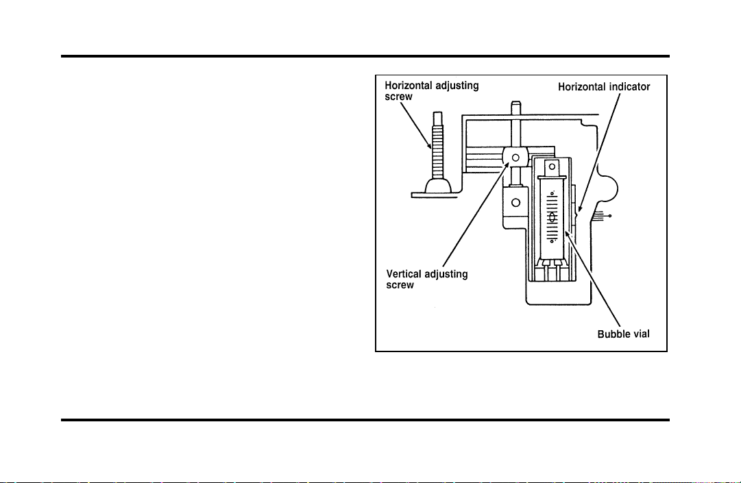
265
Before adjusting your headlamps, you must make
sure that the air suspension has been adjusted to
the proper ride height. In order to do this:
1. Position the vehicle on a level surface.
2. Make sure the air suspension switch in the
luggage compartment is in the ON position.
3. Turn the ignition key to the ON position.
4. Open and close the driver’s door to allow the
air suspension to fully level.
File:11fnmcc.ex
Update:Fri Sep 6 08:51:16 1996

266
Horizontal aim adjustment
1. Open the hood and lift the front end cover
from its velcro attachments. Locate the
horizontal level indicator and adjustment screw.
2. Use a 4mm socket and ratchet to turn the
horizontal adjusting screw until the horizontal
indicator is in line with the “0” reference.
Vertical aim adjustment
NOTE: The numbers shown on the vial indicate
beam direction in degrees up or down.
1. Locate the vertical level indicator and
adjustment screw.
2. Use a 4mm socket and ratchet to turn the
vertical adjustment screw until the bubble in
the horizontal level indicator is centered in the
vial.
3. Replace the front end cover and close the
hood.
File:11fnmcc.ex
Update:Fri Sep 6 08:51:16 1996
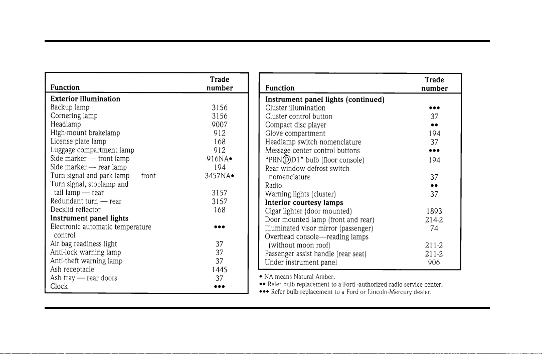
267
Bulb specifications
File:11fnmcc.ex
Update:Fri Sep 6 08:51:16 1996

268
Cleaning Your Vehicle
Washing and Polishing Your Vehicle
Wash the outside of your vehicle, including the
underside, with a mild detergent.
DO NOT:
❑
Wash your vehicle with hot water
❑
Wash your vehicle while it sits in direct
sunlight
❑
Wash your vehicle while the body is hot
Pollen, bird droppings and tree sap can damage the
paint, especially in hot weather. Wash your vehicle
as often as necessary to keep it clean.
Take similar precautions if your vehicle is exposed
to chemical industrial fallout.
Paint damage resulting from fallout is not related to
a defect inpaint materials or workmanship and
therefore is not covered by warranty. Ford,
however, believes that continual improvement in
customer satisfaction is a high priority. For this
reason, Ford has authorized its dealers to repair, at
no charge to the owner, the surfaces of new
vehicles damaged by environmental fallout within
12 months or 12,000 miles (20,000 km) of
purchase, whichever comes first. Customers may be
required to bring their vehicle in for inspection by a
Ford representative.
Polish your vehicle to remove harmful deposits and
protect the finish.
Cleaning Chrome and Aluminum Parts
Wash chrome and aluminum parts with a mild
detergent. Do not use steel wool, abrasive cleaners,
fuel, or strong detergents.
File:11fnmcc.ex
Update:Fri Sep 6 08:51:16 1996

269
Cleaning Plastic Parts
Some of your vehicle’s exterior trim parts are
plastic. Clean with a tar and road oil remover if
necessary. Use a vinyl cleaner for routine cleaning.
Do not clean plastic parts with thinners, solvents or
petroleum-based cleaners.
If you have your vehicle rustproofed, remove
oversprayed rustproofing with a tar and road oil
remover. If rustproofing is not removed from plastic
and rubber parts, it can cause deterioration.
Cleaning the Safety Belts
Clean the safety belts with any mild soap solution
that is recommended for cleaning upholstery or
carpets. Do not bleach or dye the belt webbing
because this may weaken it.
Cleaning the Instrument Panel Lens
Clean the instrument panel lens and woodtone trim
with a soft cloth and a glass cleaner. Do not use
paper towel or any abrasive cleaner to clean either
the lens or the woodtone trim as these may cause
scratches.
Cleaning the Exterior Lamps
Do not use dry paper towel, chemical solvents or
abrasive cleaners to clean the lamps, as these may
cause scratches or crack the lamps.
Cleaning the Interior Lamps
Your interior dome lamps and map lamps are plastic
and should be cleaned with a mild detergent
diluted in water. Rinse them with clear water.
File:11fnmcc.ex
Update:Fri Sep 6 08:51:16 1996

270
Cleaning the Seats
Leather
For routine cleaning, wipe the surface with a soft,
damp cloth. For more thorough cleaning, wipe the
surface with a leather and vinyl cleaner or a mild
soap.
Wipe the surface with a damp, soft cloth, then dry
and buff with a dry, soft cloth.
Fabric
Remove dust and loose dirt with a whisk broom or
a vacuum cleaner. Remove fresh spots immediately.
Follow the directions that come with the cleaner.
NOTE: Before using any cleaner, test it on a small,
hidden area of fabric. If the fabric’s color or texture
is adversely affected by a particular cleaner, do not
use it.
Cleaning the Wheels
Wash the wheels with the same detergent you use
to wash your vehicle’s body. Do not use acid-based
wheel cleaners, steel wool, abrasives, fuel, or strong
detergents. These substances will damage protective
coatings. Use tar and road oil remover to remove
grease and tar.
NOTE: Before going to a car wash, find out if the
brushes are abrasive.
If you have whitewall tires that are difficult to clean
with regular detergent, use whitewall tire cleaner.
Follow the directions on the container and rinse the
tires with plenty of clean water.
File:11fnmcc.ex
Update:Fri Sep 6 08:51:16 1996
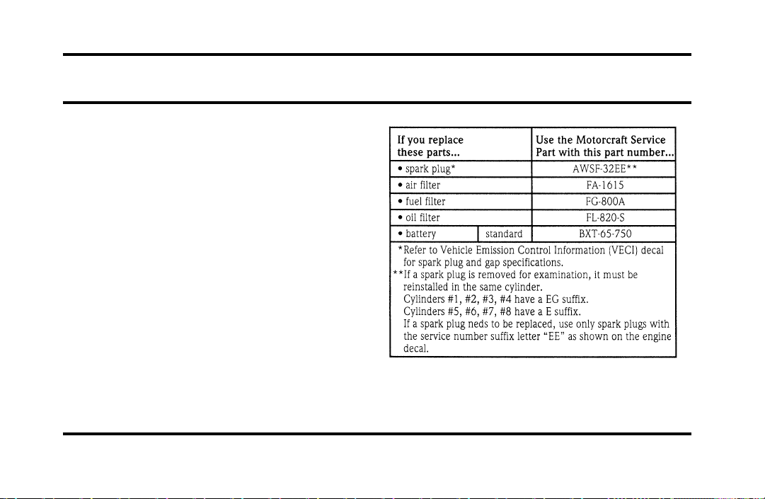
271
Capacities and Specifications
Refill Capacities, Motorcraft Parts,
and Lubricant Specifications
Motorcraft Parts
File:12fncsc.ex
Update:Mon Sep 9 10:15:52 1996
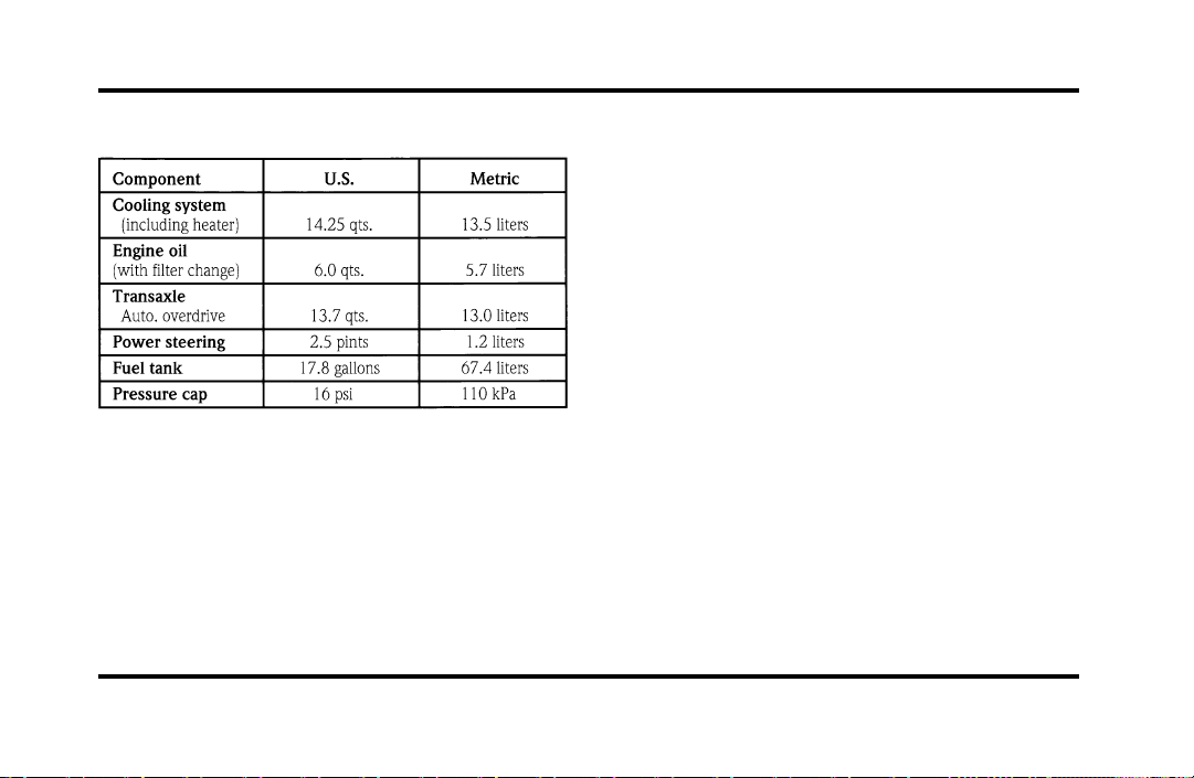
272
Fluid Specifications and Capacities
File:12fncsc.ex
Update:Mon Sep 9 10:15:52 1996
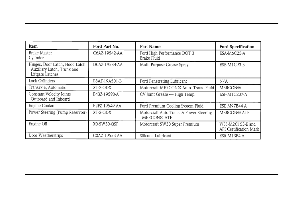
273
Lubricant Specifications
File:12fncsc.ex
Update:Mon Sep 9 10:15:52 1996

274
NOTE: Rear axle lube quantities must be replaced
every 100,000 miles (160,000 km) or if the axle
has been submerged in water. Otherwise, the lube
should not be checked or changed unless a leak is
suspected or repair required.
Vehicle Storage
Maintenance Tips
If you plan on storing your vehicle for an extended
period of time (60 days or more), refer to the
following maintenance recommendations to ensure
your vehicle stays in good operating condition.
General
❑
Store all vehicles in a dry, ventilated place.
❑
Protect from sunlight, if possible.
❑
If vehicles are stored outside, they require
regular maintenance to protect against rust and
damage.
Body
❑
Wash vehicle thoroughly to remove dirt, grease,
oil, tar or mud from exterior surfaces, rear
wheel housing and underside of front fenders.
❑
Periodically wash vehicles stored in exposed
locations.
❑
Touch-up raw or primed metal to prevent rust.
❑
Cover chrome and stainless steel parts with a
thick coat of auto wax to prevent discoloration.
Re-wax as necessary when the vehicle is
washed.
❑
Lubricate all hood, door and trunk lid hinges
and latches with a light grade oil.
❑
Cover interior soft trim to prevent fading.
❑
Keep all rubber parts free from oil and solvents.
File:12fncsc.ex
Update:Mon Sep 9 10:15:52 1996

275
Engine
❑
Start engine every 15 days. Run at fast idle
until it reaches normal operating temperature.
❑
With your foot on the brake, shift through all
the gears while the engine is running.
Fuel system
❑
Fill fuel tank with high-quality, premium
unleaded fuel until the first automatic shutoff of
the fuel pump nozzle.
NOTE: During extended periods of vehicle storage
(60 days or more), fuel may deteriorate due to
oxidation. This can damage rubber and other
polymers in the fuel system and may also clog small
orifices.
Ford Gas Stabilizer should be added whenever
actual or expected storage periods exceed 60 days.
Follow the instructions on the label. The vehicle
should then be operated at idle speed to circulate
the additive throughout the fuel system.
A volatile corrosion inhibitor added to the fuel
system will protect the fuel system’s inner surfaces
from corrosion. Follow the instructions packaged
with the product.
Cooling system
❑
Protect against freezing temperatures.
File:12fncsc.ex
Update:Mon Sep 9 10:15:52 1996

276
Battery
❑
Check and recharge as necessary.
❑
Keep connections clean and covered with a
light coat of grease.
❑
If storing your vehicle for more than 30 days
without recharging the battery, disconnect the
battery cables to ensure battery charge is
maintained for quick starting. NOTE: If battery
cables are disconnected, it will be necessary to
reset any memory features (eg. radio presets).
Brakes
❑
Make sure brakes and parking brake are fully
released.
Tires
❑
Maintain recommended air pressures.
Miscellaneous
❑
Make sure all linkages, cables, levers and clevis
pins under vehicle are covered with grease to
prevent rust.
❑
Move vehicles at least 25 feet (8 m) every 15
days to lubricate working parts and prevent
corrosion.
File:12fncsc.ex
Update:Mon Sep 9 10:15:52 1996

279
Customer Assistance
If You Have a Service Problem
Ford Motor Company has authorized Ford and
Lincoln-Mercury dealerships that can service your
vehicle for you. This chapter tells you how to get
service or maintenance for your vehicle.
Service/Maintenance Concerns
(U.S. or Canada)
Ford recommends taking your vehicle to your
selling dealer who wants to ensure your continued
satisfaction. You may, however, take your vehicle to
any authorized Ford or Lincoln-Mercury dealer. In
most cases, your dealer will be able to resolve your
concern.
If you are not satisfied with the service you
received from your dealership’s service department,
talk to the service manager at the dealership, or if
you still are not satisfied, talk to the owner or
general manager of the dealership. In most cases,
you will have your concern resolved at this level.
If you are away from home when your vehicle
needs to be serviced, or if you need more help than
the dealer gave you, contact the Ford Customer
Assistance Center to find an authorized dealership
that may be able to help you.
File:14fnhsc.ex
Update:Mon Sep 9 10:16:08 1996
280
If you have any questions or concerns that the
dealership cannot answer, contact the Customer
Assistance Center.
If you still have a complaint involving a warranty
dispute, you may wish to contact the Dispute
Settlement Board (U.S. only) or the Canadian Motor
Vehicle Arbitration Plan (CAMVAP) in Canada.
A warranty dispute must be submitted to the
Dispute Settlement Board before taking action under
the Magnuson-Moss Warranty Act, or to the extent
allowed by state law, before pursuing replacement
or repurchase remedies provided by certain state
laws. This dispute handling procedure is not
required prior to enforcing state created rights or
other rights which are independent of the
Magnuson-Moss Warranty Act or state replacement
or repurchase laws.
The Dispute Settlement Board
(U.S. Only)
The Dispute Settlement Board is:
❑
an independent, third-party arbitration program
for warranty disputes
❑
available free to owners and lessees of qualifying
Ford Motor Company vehicles
The Dispute Settlement Board may not be available
in all states. Ford Motor Company reserves the right
to change eligibility limitations, modify procedures
and/or to discontinue this service without notice
and without incurring obligations.
File:14fnhsc.ex
Update:Mon Sep 9 10:16:08 1996

281
What Kind of Cases Does the Board
Review?
The Board reviews all warranty performance
complaints on Ford, Mercury and Lincoln cars and
Ford and Mercury light trucks under the new
vehicle limited warranty that have not been
resolved by either a dealer or Ford Motor Company,
except those involving:
❑
a non-Ford product
❑
a non-Ford dealership
❑
a vehicle sales transaction
❑
request for reimbursement of consequential
expenses. Expenses incidental to the warranty
complaint being reviewed are eligible for
consideration.
❑
items not covered by the new vehicle limited
warranty
❑
items covered by a service contract
❑
alleged liability claims
❑
property damage where the damage is
significant when compared to the economic loss
alleged under the warranty dispute
❑
cases currently in litigation
❑
vehicles not used primarily for family, personal,
or household purposes (except in states where
the Dispute Settlement Board is required to
review commercial vehicles)
Complaints involving vehicles in which applicable
new vehicle limited warranties have expired at
receipt of your application are not eligible. Eligibility
may differ according to state law. For example, see
the unique brochures for California and Wisconsin
purchasers/lessees.
File:14fnhsc.ex
Update:Mon Sep 9 10:16:08 1996

282
How does the Board Work?
The Board consists of:
❑
three consumer representatives
❑
a Ford or Lincoln/Mercury dealer
Consumer candidates for Board membership are
recruited and trained by an independent consulting
firm. Dealers are chosen because of their business
leadership qualities.
What the Board needs
To have your case reviewed you must complete the
application in the DSB brochure and mail it to the
address provided on the application form.
Your application is reviewed and, if it is determined
to be eligible, you will receive an acknowledgment
indicating:
❑
the file number assigned to your application
❑
the toll-free phone number of the DSB’s
independent administrator
Your dealership and a Ford Motor Company
representative are asked to submit statements at this
time.
To review your case properly, the Board needs the
following information:
❑
legible copies of all documents and maintenance
or repair orders relevant to the case
❑
the year, make, model, and Vehicle
Identification Number (VIN) listed on your
vehicle ownership license
❑
the date of repair(s) and mileage at the time of
occurrence(s)
❑
the current mileage
❑
the name of the dealer who sold or serviced the
vehicle
❑
a brief description of your unresolved concern
File:14fnhsc.ex
Update:Mon Sep 9 10:16:08 1996

283
❑
a brief summary of the action taken with the
dealer and Ford Motor Company
❑
the names (if known) of all the people you
contacted at the dealership
❑
a description of the action you expect to resolve
your concern
Should your case NOT qualify for review, a letter of
explanation will be mailed to you.
Oral presentations
If the involved vehicle is within 36 months and
36,000 miles of the warranty start date, you have
the right to make an oral presentation before the
Board. Indicate your choice to do so on the
application. Oral presentations may also be
requested by the Board.
Making a decision
Board members will review all available information
related to the complaint, including oral
presentations, if necessary. They then arrive at a fair
and impartial decision, decided by a simple majority
vote.
Because the Board usually meets only once a
month, some cases may take longer than 30 days to
be reviewed. The Board makes every effort to
resolve each case within 40 days of receiving the
consumer application form.
After your case is reviewed, the Board mails you a
decision letter. The Board also provides a form on
which to accept or reject the Board’s decision. The
decisions of the Board are binding on the dealer
and Ford, but not on consumers who may elect to
pursue other remedies available to them under state
or federal law. Decisions of the Board may be
presented as evidence by any party in subsequent
legal proceedings that may be initiated, where
allowed by law.
File:14fnhsc.ex
Update:Mon Sep 9 10:16:08 1996
284
To Request a DSB
Brochure/Application
For a brochure/application, speak to your dealer or
write to the Board at the following address:
Ford of Canada Customer
Assistance
If you live in Canada and have any questions or
concerns that the dealership cannot answer, contact
the Lincoln Centre.
Please have the following information available
when contacting the Lincoln Centre:
❑
your telephone number (both business and
home)
❑
the name of the dealer and the city where the
dealership is located
❑
the year and make of your vehicle
❑
the date purchased
❑
the current mileage on your vehicle
❑
your Vehicle Identification Number (VIN) listed
on your vehicle ownership license
File:14fnhsc.ex
Update:Mon Sep 9 10:16:08 1996
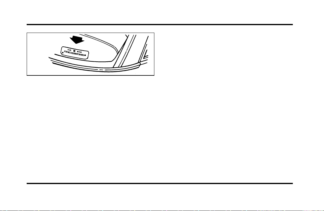
285
Vehicle Identification Number (VIN/Serial
Number)
Mediation/Arbitration Program
(Canada Only)
In those cases where you continue to feel that the
efforts by Ford and the dealer to resolve a
factory-related vehicle service concern have been
unsatisfactory, Ford of Canada participates in an
impartial third party mediation/arbitration program
administered by the Canadian Motor Vehicle
Arbitration Plan (CAMVAP).
The CAMVAP program is a straight-forward and
relatively speedy alternative to resolve a
disagreement when all other efforts to produce a
settlement have failed. This procedure is without
cost to you and is designed to eliminate the need
for lengthy and expensive legal proceedings.
In the CAMVAP program, impartial third-party
Arbitrators conduct hearings at mutually convenient
times and places in an informal environment. These
impartial Arbitrators review the positions of the
parties, make decisions and, where appropriate,
render awards to resolve disputes. CAMVAP
decisions are fast, fair and final as the arbitrator’s
award is binding on both you and Ford of Canada.
CAMVAP services are available in all territories and
provinces, except Quebec. For more information,
without charge or obligation, call your CAMVAP
Provincial Administrator directly at 1-800-207-0685.
File:14fnhsc.ex
Update:Mon Sep 9 10:16:08 1996

286
Getting Help Outside the U.S.
and Canada
Before you export your vehicle to a foreign country,
contact the appropriate foreign embassy or consulate
to make sure local regulations do not prevent you
from registering your vehicle. Officials at the
embassy can also help you decide whether you
should import your vehicle to that country.
Officials at the embassy or consulate can tell you
where to get unleaded fuel. If you cannot get
unleaded fuel or can get only fuel with an
anti-knock index that is lower than your vehicle
needs, contact a district or owner relations office
before you leave the U.S. or Canada.
Use of leaded fuel in your vehicle without a proper
conversion may damage the effectiveness of your
emissions control system and may cause engine
knocking or serious engine damage. Ford Motor
Company is not responsible for any damage that is
caused by use of improper fuel.
You may also have difficulty importing your vehicle
back into the U.S. if you use leaded fuel.
File:14fnhsc.ex
Update:Mon Sep 9 10:16:08 1996

287
If your vehicle must be serviced while you are
traveling or living in Central or South America, the
Caribbean, or the Middle East, contact the nearest
Ford dealership. If the dealership cannot help you,
write to:
If you are in other foreign countries, contact the
nearest Ford dealership. If the dealership cannot
help you, they can direct you to the appropriate
Ford affiliate office.
If you buy your vehicle in North America and then
relocate outside of the U.S. or Canada, register your
Vehicle Identification Number and new address
with Ford Motor Company Export Operations.
File:14fnhsc.ex
Update:Mon Sep 9 10:16:08 1996
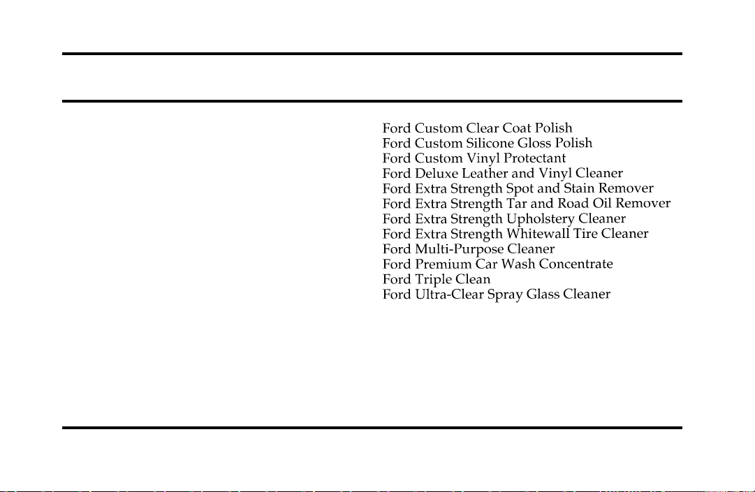
289
Accessories
Ford Accessories for Your Vehicle
A wide selection of accessories is available through
your local authorized dealer. These fine accessories
have been engineered specifically to fulfill your
automotive needs. They are custom designed to
complement the style and aerodynamic appearance
of your Ford-built vehicle. In addition, each
accessory is made from high quality materials and
meets or exceeds Ford’s rigid engineering and safety
specifications. That is why Ford brand accessories
are warranted for up to 12 months or 12,000 miles
(20,000 km), whichever comes first. See your
dealer for complete warranty information and
accessory availability.
Ford has many fine products available from your
dealer to clean your vehicle and protect its finishes.
For best results, use the following, or products of
equivalent quality:
File:15fnacc.ex
Update:Mon Sep 9 10:16:23 1996
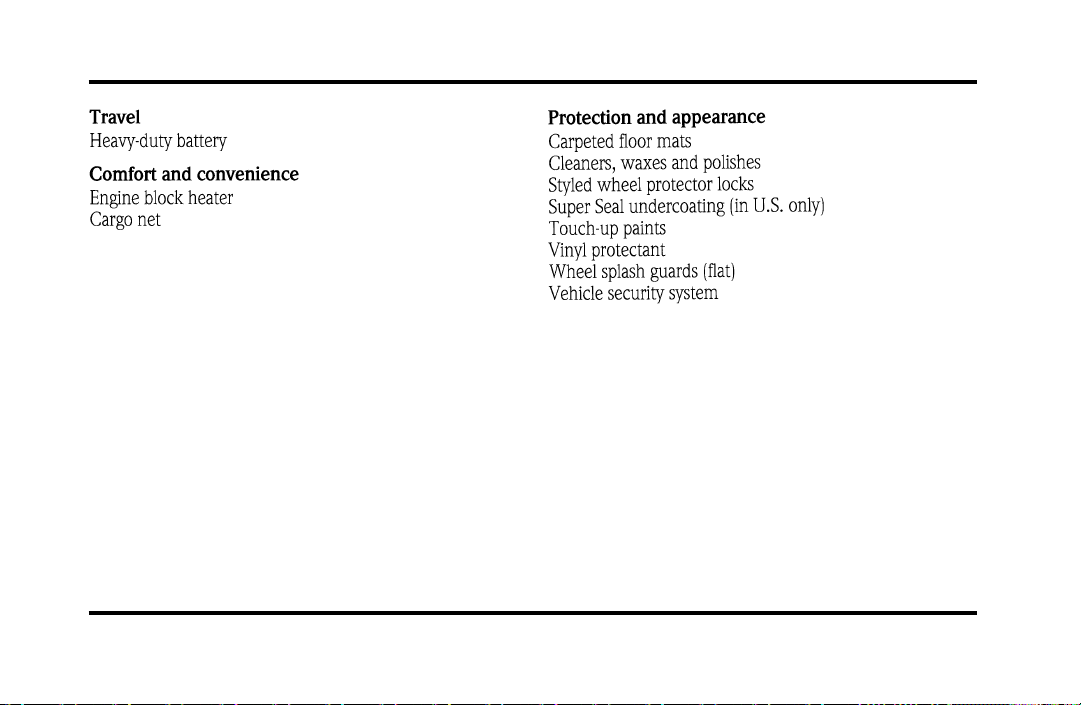
290
NOTE: When adding accessories, equipment,
passengers, and luggage to your vehicle, do not
exceed the total weight capacity of the vehicle or of
the front or rear axle (GVWR, GAWR as shown on
the Safety Compliance Certification Label). Consult
your dealer for specific weight information.
File:15fnacc.ex
Update:Mon Sep 9 10:16:23 1996

291
NOTE: The Federal Communications Commission
(FCC) or the Canadian Radio Telecommunications
Commission (CRTC) regulates the use of mobile
communications systems — such as two-way radios,
telephones, and theft alarms — that are equipped
with radio transmitters. Any such equipment
installed in your vehicle should comply with FCC
or CRTC regulations and should be installed only by
a qualified technician.
NOTE: Mobile communications systems may harm
the operation of your vehicle, particularly if they are
not properly designed for automotive use or are not
properly installed. For example, when operated,
such systems may cause the engine to stumble or
stall. In addition, such systems may themselves be
damaged or their operation affected by operating
your vehicle. (Citizens band [CB] transceivers,
garage door openers, and other transmitters whose
power output is 5 watts or less will not ordinarily
affect your vehicle’s operation.)
NOTE: Because we have no control over the
installation, design, or manufacture of such systems,
Ford cannot assume responsibility for any adverse
effects or damage that may result if you use this
equipment.
File:15fnacc.ex
Update:Mon Sep 9 10:16:23 1996

292
File:15fnacc.ex
Update:Mon Sep 9 10:16:23 1996

293
File:15fnacc.ex
Update:Mon Sep 9 10:16:23 1996

294
File:15fnacc.ex
Update:Mon Sep 9 10:16:23 1996

295
File:15fnacc.ex
Update:Mon Sep 9 10:16:23 1996

296
File:15fnacc.ex
Update:Mon Sep 9 10:16:23 1996
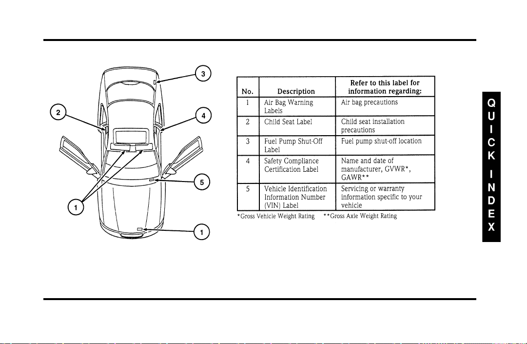
297
File:16fnqic.ex
Update:Tue Sep 17 08:28:40 1996

298
Front Exterior View
File:16fnqic.ex
Update:Tue Sep 17 08:28:40 1996
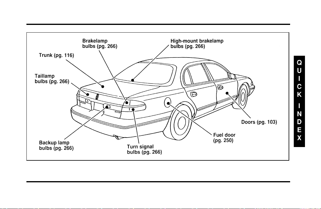
299
Rear Exterior View
File:16fnqic.ex
Update:Tue Sep 17 08:28:40 1996
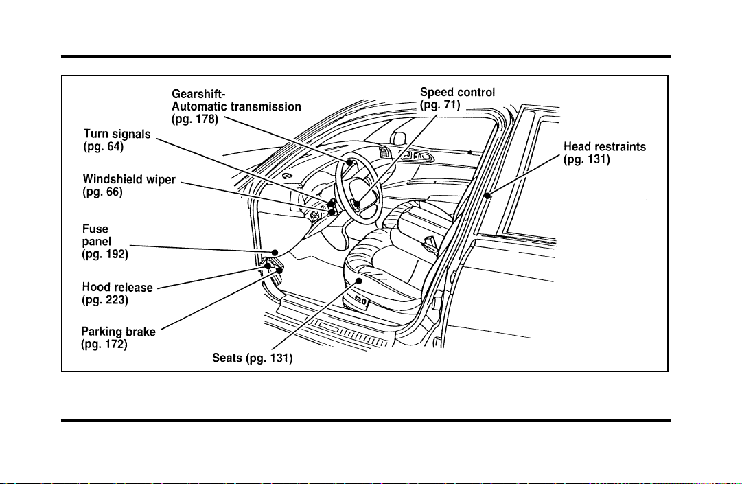
300
Entrance View
File:16fnqic.ex
Update:Tue Sep 17 08:28:40 1996
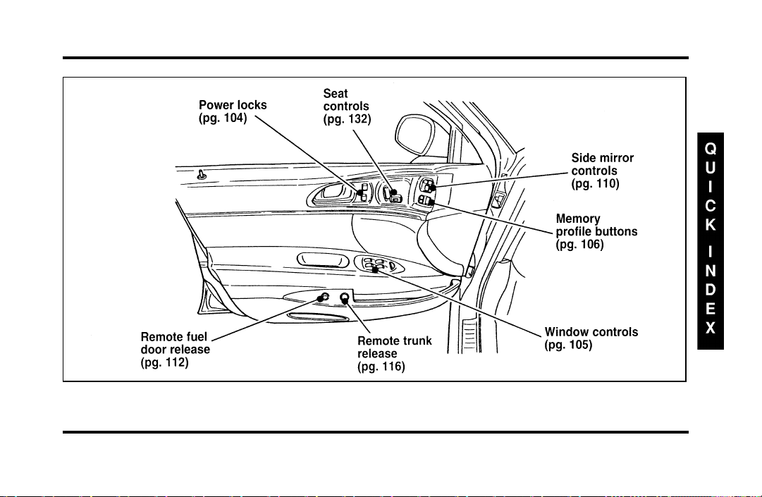
301
Driver’s Door
File:16fnqic.ex
Update:Tue Sep 17 08:28:40 1996
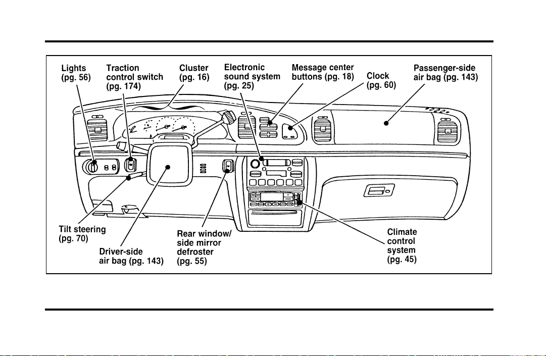
302
Instrument Panel
File:16fnqic.ex
Update:Tue Sep 17 08:28:40 1996
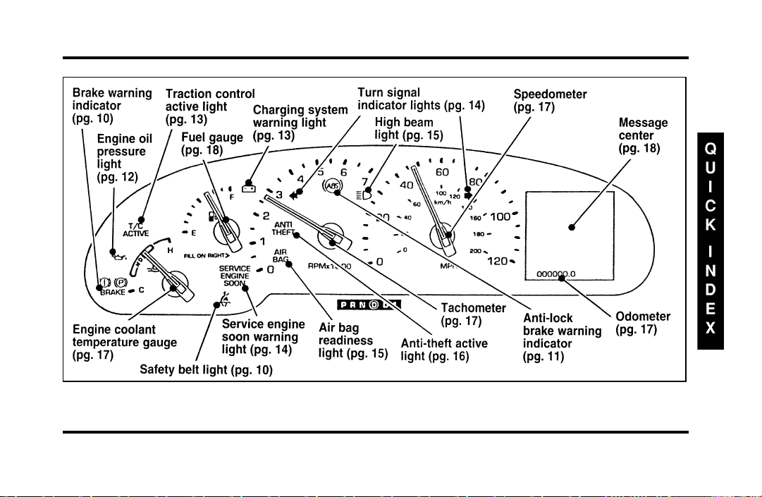
303
Instrument Cluster
File:16fnqic.ex
Update:Tue Sep 17 08:28:40 1996
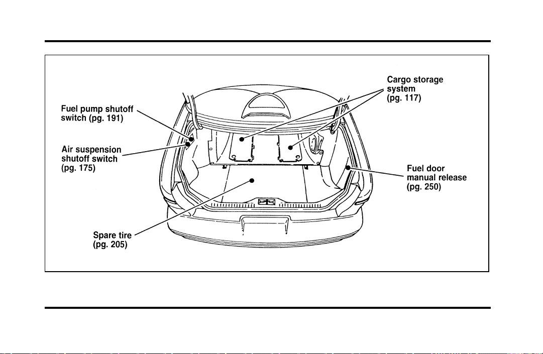
304
Trunk
File:16fnqic.ex
Update:Tue Sep 17 08:28:40 1996
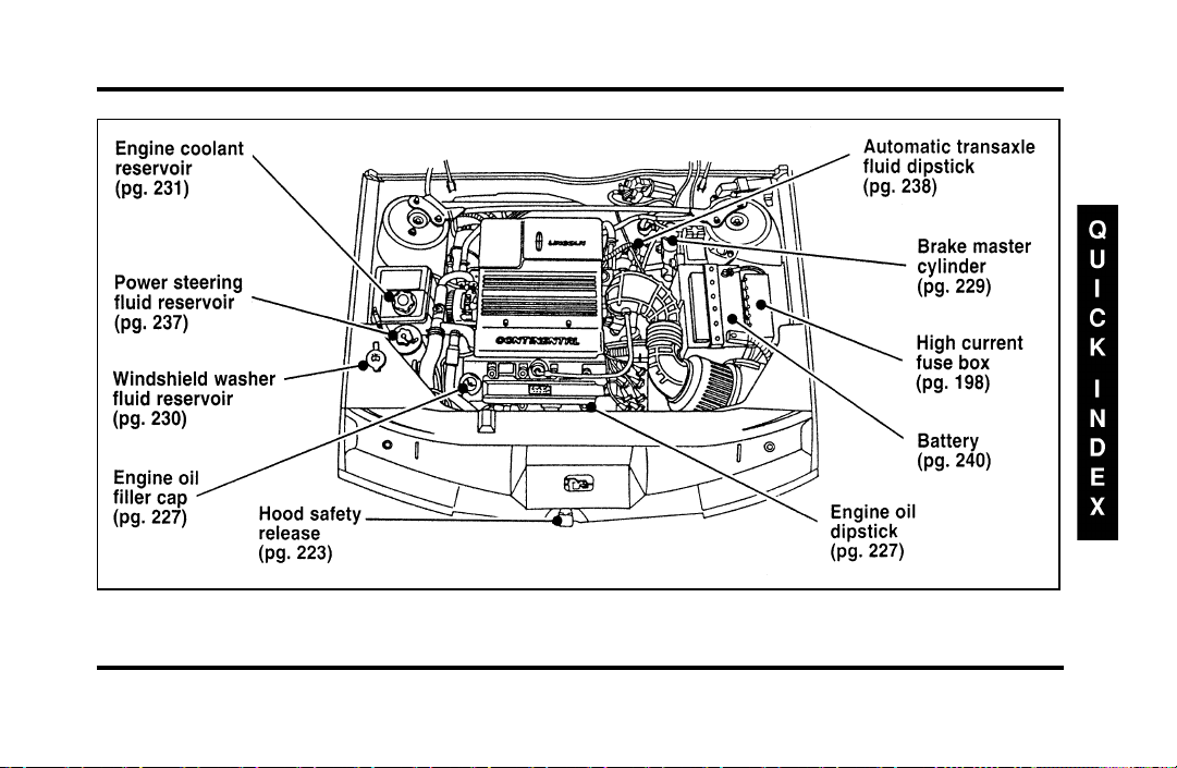
305
Engine Compartment
File:16fnqic.ex
Update:Tue Sep 17 08:28:40 1996

306
Index
A
ABS warning light (see Anti-lock
brake system) ............ 11
Accessory position on the ignition .... 62
Accident damage ............ 220
Air bag supplemental restraint system . . . 143
and child safety seats ......... 149
description .......... 143, 145
driver air bag ......... 143, 145
indicator light ............ 15
operation .............. 145
passenger air bag........... 145
service and information labels ..... 145
tone generator............ 147
Air cleaner filter
location............... 224
specifications ............ 271
Air conditioning, electronic automatic
temperature control system ...... 45
Air suspension
air leveling disabled warning,
message center........... 20
description .............175
Alarm, activating remote personal.....124
Aluminum wheels ...........250
Antenna, radio (see Electronic
sound system) .......... 25,31
Antifreeze (see Engine coolant) ......231
Anti-lock brake system (ABS)
description .............171
noise ................171
see also Brake ............171
warning light ............ 11
Anti-theft lug nuts and key........210
Anti-theft system
arming the system ..........127
description .......... 126, 127
File:fnixc.ex
Update:Tue Sep 17 08:28:54 1996

307
Anti-theft system (continued)
disarming an untriggered system .... 128
disarming a triggered system...... 129
triggering ........... 126, 128
warning light ............ 16
Appeals (see Dispute settlement board) . . 280
Assistance (see Customer assistance) . . . 279
Audio system (see Electronic
sound system) ............ 25
Autolamp system (see Headlamps) .... 56
Automatic transaxle
driving with............. 177
fluid, adding.......... 238, 240
fluid, checking......... 238, 239
fluid, refill capacities ......... 272
fluid, specification .......... 273
B
Basic vehicle warranty........... 4
Battery................240
acid, treating emergencies .......241
battery saver.............126
charging system warning light ..... 13
disconnecting ............216
how to service............240
jumping a disabled battery.......211
maintenance-free ...........240
proper disposal, recycling .......241
replacement, specifications.......271
servicing ..............240
voltage gauge ............ 13
when storing your vehicle.......276
Brake fluid...............229
brake warning light.......... 10
checking and adding .........229
File:fnixc.ex
Update:Tue Sep 17 08:28:54 1996

308
description ............. 229
specifications ............ 273
Brakes ................ 171
adjustment ............. 171
anti-lock .............. 171
anti-lock brake system (ABS)
warning light ........... 11
applying the brakes.......... 171
brake warning light.......... 10
fluid, checking and adding....... 229
fluid, refill capacities ...... 229, 272
fluid, specifications .......... 273
front disc .............. 171
if brakes do not grip well ....... 171
master cylinder ........... 229
new brake linings ........... 5
noise............. 171, 172
parking ............... 172
power braking ............ 171
servicing .............. 229
trailer ............... 188
when storing your vehicle....... 276
Break-in period.............. 5
Brights (high beams) .......... 15
Bulbs, replacing ............261
halogen ...............261
headlamps..............262
C
Canada, customer assistance .......284
Canada, warranty information ....... 4
Canadian Motor Vehicle Arbitration Plan
(CAMVAP)..............285
Capacities for refilling fluids .......272
Car seats for children
(see Child safety seats) ........149
Cassette tape player (see Electronic sound
system) ............... 32
Catalytic converter ...........258
CD player (see Electronic sound system) . . 35
Chains, tires ..............250
Changing a tire.............205
Charging system warning light ...... 13
Childproof locks ............103
File:fnixc.ex
Update:Tue Sep 17 08:28:54 1996

309
Child safety restraints .......... 148
child safety belts ........... 162
child safety seats........... 149
Child safety seats............ 149
and air bags ............. 149
attaching with tether straps ...... 160
automatic locking mode
(retractor) .......... 140, 149
in front seat............. 149
in rear outboard seat ......... 149
in rear seat ............. 149
tether anchorage hardware ...... 161
Chime
headlamps on ............ 15
key in ignition............ 63
safety belt.............. 10
Circuit breakers, see also fuses ...... 192
Cleaning your vehicle .......... 268
chrome and aluminum parts ...... 268
exterior............... 269
exterior lamps ............ 269
fabric................ 270
headlamps..............269
instrument panel......... 7,269
interior ...............269
interior lamps ............269
mirrors ............. 93,111
plastic parts .............269
polishing ..............268
rustproofing .............268
safety belts .............269
tail lamps ..............269
upholstery and interior trim ......269
washing...............268
waxing ...............268
wheels ...............270
Climate control system
air conditioning ........... 45
electronic automatic temperature
control .............. 45
heating ............... 45
Clock ................. 60
File:fnixc.ex
Update:Tue Sep 17 08:28:54 1996

310
Clutch
fluid reservoir ............ 229
specifications ............ 273
Cold engine starting .......... 166
Combination lap and shoulder belts . 135, 137
Compact disc player (see Electronic sound
system) ............... 35
Compact disc radio (see Electronic
sound system) ............ 27
Console, description .......... 113
Controls, mirrors ............ 92
Convenience kit in cargo area ...... 206
Coolant (see Engine coolant) ....... 231
checking and adding ......... 231
preparing for storage ......... 275
refill capacities............ 272
specifications ............ 273
temperature gauge .......... 17
warnings .............. 231
Cooling fan .............. 221
Crankcase emission filter ........ 271
Customer Assistance Centre,
Ford of Canada ............284
D
Daytime running light system ...... 56
Defects, reporting............277
Dipstick ................227
automatic transaxle fluid .... 238, 239
engine oil ..............227
power steering fluid .........237
Disabled vehicle (see Towing) ......217
Dispute Settlement Board ........280
Doors .................103
lubricant specifications ........273
Driving under special conditions
heavy load .............183
towing a trailer ...........185
E
Electrical system, fuses ...... 192, 203
Electronic sound system
antenna............... 31
tuning the radio ........... 27
File:fnixc.ex
Update:Tue Sep 17 08:28:54 1996

311
Electronic sound system (continued)
warranty and service information.... 44
Electronic stereo cassette radio
(see Electronic sound system) ..... 27
Electronic stereo radio (see Electronic
sound system) ............ 27
Emergencies, roadside
fuel ................ 255
jump-starting ............ 211
towing ............... 217
Emergency brake (parking brake) ..... 172
Emission control system ......... 258
catalytic converter .......... 258
emissions warranty .........4,258
Engine
does not start ......... 167, 191
fuel injected engine, starting. . . 165, 166
fuel pump shut-off switch ....... 191
preparing to start .......... 165
refill capacities............ 272
service points ............ 224
starting ............... 166
starting after a collision ........191
storing your vehicle ...... 274, 275
Engine block heater...........168
Engine coolant .............231
checking and adding .........231
disposal............ 220, 240
preparing for storage .........275
proper solution ........ 220, 240
recovery reservoir ....... 224, 231
refill capacities............272
specifications ............273
temperature gauge .......... 17
Engine coolant temperature gauge..... 17
description ............. 17
mechanical ............. 17
Engine coolant temperature
guage:electronic ........... 17
Engine fan...............221
Engine knocking ............253
Engine oil ...............226
“break-in” oils ............. 5
changing oil and oil filter .... 227, 228
File:fnixc.ex
Update:Tue Sep 17 08:28:54 1996

312
checking and adding ......... 227
check oil warning light ........ 12
dipstick............... 227
disposal............ 220, 240
engine oil pressure warning light.... 12
filter, specifications.......... 271
low oil warning light ......... 12
refill capacities............ 272
specifications ......... 226, 273
synthetic oil............. 226
viscosity .............. 226
F
Fan.................. 221
engine fan, avoiding injury ...... 221
Flashers, hazard ............ 68
Flashing the lights ........... 65
Flat tire ................ 205
Fluid refill capacities .......... 272
Ford Dispute Settlement Board ...... 280
Ford Motor Company of Canada ..... 284
Ford of Canada Customer
Assistance Centre...........284
Foreign registration ...........286
French owner guides, how to obtain .... 3
Fuel .................251
calculating fuel economy .......256
capacity...............272
choosing the right fuel ........253
comparisons with EPA fuel
economy estimates .........257
filling your vehicle with fuel......251
filter, specifications ..........271
fuel filler door release lever ......251
fuel gauge.............. 18
octane rating ............253
quality ...............253
running out of fuel ..........256
safety information relating to
automotive fuels ..........255
storing your vehicle .........275
treating emergencies .........255
Fuel cap................251
removing ..............251
File:fnixc.ex
Update:Tue Sep 17 08:28:54 1996

313
Fuel cap (continued)
replacing .............. 251
Fuel filler door ............. 251
remote release............ 251
Fuel filter, specifications......... 271
Fuel gauge............... 18
Fuel pump shut-off switch
engine does not start ......... 191
starting after a collision ........ 191
Fuse panels .............. 192
engine compartment ......... 198
instrument panel........... 203
Fuses
charts ............ 192, 203
checking and replacing ........ 203
G
Gas cap (see Fuel cap) ......... 251
Gas mileage (see Fuel economy) . . 253, 254
Gasoline (see Fuel) ........... 251
Gauges, Electronic
engine coolant temperature gauge . . . 17
fuel gauge.............. 18
odometer .............. 17
speedometer............. 17
Gauges, Mechanical
engine coolant temperature gauge . . . 17
fuel gauge.............. 18
odometer .............. 17
speedometer............. 17
tachometer ............. 17
GAWR (Gross Axle Weight Rating)
calculating..............184
definition ..............183
driving with a heavy load .......183
location...............183
Gearshift
automatic operation....... 177, 178
column-mounted ........ 178, 179
locking the gearshift ......... 62
positions ..............178
shifting the gears...........178
Gearshift:shifting the gears........178
GVWR (Gross Vehicle Weight Rating) . . . 183
File:fnixc.ex
Update:Tue Sep 17 08:28:54 1996

314
calculating ............. 184
definition .............. 183
driving with a heavy load ....... 183
location............... 183
H
Hazard flashers............. 68
Headlamps
aiming ............... 264
autolamp system ........... 57
checking alignment.......... 261
cleaning .............. 261
daytime running lights ........ 56
flashing............... 65
high beam ............. 65
replacing bulbs ........... 261
turning on and off .......... 57
warning chime............ 15
Head restraints............. 131
Heated mirrors............. 112
Heating
electronic automatic temperature control
system .............. 45
High beams
indicator light ............ 15
operation ............ 56,65
Hood .................223
latch location ............223
lubrication specifications .......273
release lever.............223
working under the hood .......221
Horn ................. 69
I
Idle, relearning.......... 216, 221
Ignition
chime ............... 63
positions of the ignition........ 62
removing the key .......... 63
Indicator lights and chimes (see Lights) . . . 7
Infant seats (see Safety seats).... 148, 149
Instrument panel ............. 7
cleaning...............269
Interval wipers ............. 66
File:fnixc.ex
Update:Tue Sep 17 08:28:54 1996

315
J
Jack ................. 206
operation ........... 207, 208
positioning .......... 207, 208
storage ............... 206
Jump-starting your vehicle
attaching cables ........... 214
disconnecting cables ......... 216
K
Keyless entry system
locking and unlocking doors ...... 119
programming entry code ....... 121
Keys
key in ignition chime......... 63
positions of the ignition........ 62
removing from the ignition ...... 63
stuck in lock position........62,63
L
Lamps
autolamp delay system ........ 57
checking .............. 261
daytime running light system ..... 56
flashing the lamps .......... 65
hazard flashers............ 68
headlamps.............. 57
high beams ............. 65
interior lamps ............ 56
replacing bulbs............261
trailer ...............188
Lane change indicator
(see Turn signal) ......... 64,65
Lap belts ...............141
Lights, warning and indicator
airbag............... 15
anti-lock brakes (ABS)......... 11
anti-theft .............. 16
brake................ 10
charging system ........... 13
engine oil pressure .......... 12
hazard warning light ......... 68
high beam ............. 15
lowoil............... 12
oil pressure ............. 12
File:fnixc.ex
Update:Tue Sep 17 08:28:54 1996

316
rear ABS .............. 11
safety belt.............. 10
service engine soon ......... 14
theft system ............. 16
turn signal indicator ...... 14,64,65
Load limits .............. 183
GAWR ............... 183
GVWR ............... 183
trailer towing ............ 185
Lubricant specifications ......... 273
Luggage compartment .......... 116
Lug nuts ............... 207
anti-theft .............. 210
standard .............. 208
tightening sequence ......... 207
M
Maintenance schedule and record
(see separate Maintenance Schedule
and Record booklet)........... 3
Maintenance (see Servicing) ....... 219
Master cylinder, brakes .........229
Mileage, calculating fuel economy.....257
Mirrors ................ 92
automatic dimming rearview mirror. . . 92
heated ...............112
rearview .............. 92
side view mirrors .......... 92
side view mirrors (manual) ......110
Moon roof............... 91
Motorcraft parts ............271
N
National Highway Traffic Safety
Administration ............277
New vehicle break-in ........... 5
O
Octane rating .............253
Odometer ............... 17
description ............. 17
Oil filter............. 228, 271
Oil (see Engine oil) ...........226
Oil viscosity ..............226
File:fnixc.ex
Update:Tue Sep 17 08:28:54 1996

317
On-board diagnostic (OBD II) system . . . 260
Overdrive ............... 181
Overseas offices ............ 286
P
Panic alarm feature, remote
entry system ............. 124
Parking brake ............. 172
operation .............. 172
warning light ............ 10
Parts (see Motorcraft Parts) ....... 271
PCV valve, specifications ........ 271
Phone, cellular ............. 113
Power features
antenna............... 31
mirrors ............... 92
moon roof.............. 91
seats ................ 132
windows .............. 105
Power steering
dipstick............... 237
driving with power steering ...... 177
fluid, checking and adding.......237
fluid, refill capacity ..........272
fluid, specifications ..........273
Prop rod, hood .............223
R
Radio (see Electronic sound systems) . . . 25
Rear axle
lubricant specification.........273
refill capacity ............272
Rearview mirror ............ 92
Rear window, washer reservoir ......230
Refill capacities for fluids ........272
Regulations, National Highway Traffic Safety
Administration ............277
Remote entry system
arming and disarming the
anti-theft system ..........124
locking/unlocking doors........123
opening the trunk ..........123
panic alarm .............124
File:fnixc.ex
Update:Tue Sep 17 08:28:54 1996

318
replacement/additional transmitters. . . 125
replacing the batteries ........ 124
Reporting safety defects ......... 277
Restraints, safety (see Safety restraints)
adult ............. 131, 135
child ................ 148
head ................ 131
infant ............ 148, 149
Reverse ................ 181
Roadside emergencies .......... 191
Rotating the tires............ 247
S
Safety belts (see Safety restraints) ..... 135
Safety chains, when towing a trailer.... 187
Safety Compliance Certification Label . . . 183
Safety defects, reporting ......... 277
Safety information relating to
automotive fuels ........... 255
Safety restraints
adjusting the safety belts . . 137, 138, 142
automatic locking mode ........ 140
automatic locking mode (retractor) . . . 140
center front lap belt .........141
center rear lap belt..........141
cleaning the safety belts........269
extension assembly ..........142
for adults ..............135
for children .............148
for infants........... 148, 149
for pregnant women .........135
head ................131
lap and shoulder belts ..... 135, 137
lap belt ...............141
maintenance.............143
proper use .............135
replacement .............143
warning light and chime ....... 10
Safety seats for children .........149
and air bags .............149
attaching with tether straps ......160
automatic locking mode
(retractor) .......... 140, 149
in front seat .............149
in rear outboard ...........149
File:fnixc.ex
Update:Tue Sep 17 08:28:54 1996

319
Safety seats for children (continued)
in rear seat ............. 149
tether anchorage hardware ...... 160
Seat belts (see Safety restraints) ..... 135
Seats ................. 131
adjusting the seats, power....... 132
child safety seats........... 149
cleaning upholstery.......... 270
head restraints............ 131
Service concerns ............ 279
Servicing your vehicle.......... 219
precautions when servicing ...... 221
servicing when you tow........ 217
Shift positions (see Gearshift) . . . 178, 179
Shoulder and lap belts
(see Safety restraints) ...... 135, 137
Shoulder belts
(see Safety restraints) ...... 137, 138
Side mirrors .............. 92
adjusting .............. 110
heated ............... 112
Sliding moon roof (see Moon roof) .... 91
Snow tires and chains..........250
Spare tire ...............205
changing the tire........ 205, 207
conventional spare ..........206
finding the spare...........206
removing the spare tire ........206
storing the flat tire ....... 206, 208
temporary spare ...........205
Spark plugs, specifications ........271
Specification chart, lubricants.......273
Speed control
turning off ............. 72
when towing a trailer.........189
Speedometer .............. 17
Starting your vehicle
preparing to start your vehicle .....165
starting a cold engine.........166
starting after a collision ........191
starting a warm engine ........166
starting your vehicle if the battery
is disabled.............211
Steering, power ............177
File:fnixc.ex
Update:Tue Sep 17 08:28:54 1996

320
Steering wheel
horn ................ 69
locking ............... 62
tilting ............... 70
Storage compartments, center console . . . 113
Storing your vehicle........... 274
Sunroof (moon roof) .......... 91
Sun visor ............... 94
Sunvisor................ 94
Supplemental air bag readiness light.... 15
Supplemental Restraint System (SRS) . . . 143
T
Tachometer .............. 17
mechanical cluster .......... 17
Tail lamps
bulb replacement........... 261
cleaning .............. 269
Temperature control (see Climate control) . 45
Tether anchor installation
(see Child restraints) ......... 160
Tilt steering wheel ........... 70
Tires .................246
changing ..............205
checking the pressure.........246
cleaning...............270
inspection and maintenance ......246
replacing ..............248
rotating ...............247
snow tires and chains.........250
spare tire ..............206
storing your vehicle .........276
tire grades .............248
treadwear ..............248
wear bands .............248
Towing a trailer (see Trailer towing) . . . 185
Towing your vehicle ..........217
using wheel dollies ..........217
with a tow truck ...........217
Trailer towing .............185
calculating maximum trailer weight . . . 185
safety chains.............187
tips ................189
trailer brakes ............188
File:fnixc.ex
Update:Tue Sep 17 08:28:54 1996

321
Trailer towing (continued)
trailer lamps............. 188
Transaxle
automatic operation ...... 177, 178
fluid, checking and adding
(automatic) ......... 238, 239
fluid, refill capacities ......... 272
lubricant specifications ........ 273
Transaxle control switch......... 181
Trunk, using the remote entry system
to open ............... 123
Tune-up specifications (VECI) ...... 260
Turn signal .............. 64
indicator lights...........14,65
lever ...............64,65
U
Used engine oil, disposal ..... 220, 240
V
Variable interval wipers ......... 66
VECI (Vehicle Emission Control Information)
decal ................260
Vehicle loading
automatic transaxles .........184
automatic transmissions ........184
calculating the load..........184
manual transaxles ..........184
manual transmissions .........184
understanding loading information . . . 183
Vehicle storage.............274
Ventilating your vehicle
(see Climate control) ....... 45,51
Viscosity (see Engine oil) ........226
Visor (see Sun visor) .......... 94
Voltmeter (see Battery voltage gauge) . . . 13
File:fnixc.ex
Update:Tue Sep 17 08:28:54 1996

322
W
Warm engine, starting.......... 166
Warning chimes
headlamps on ............ 15
key in ignition............ 63
safety belt.............. 10
Warning lights (see Lights)......... 7
Warranties................ 4
basic ................. 4
Canada ................ 4
radio ................ 44
Warranty Information Booklet ....... 4
Washer fluid.............. 66
rear window reservoir ........ 230
reservoir .............. 230
windshield ............. 230
Weight limits (GAWR, GVWR) ...... 183
Wheel bearings, lubricant specifications . . 273
Wheel dollies (see Towing) .......217
Wheels
anti-theft lugnuts...........210
cleaning...............270
covers ............ 207, 208
inspection and maintenance ......246
lug nuts...............207
Windows, power windows, operating . . . 105
Windshield, washing .......... 66
Windshield washer fluid and wipers.... 66
checking and adding fluid .......230
checking and replacing wiper blades . . 242
liftgate reservoir ...........230
operation .............. 66
reservoir ..............230
specifications ............273
variable interval wipers ........ 66
Windshield wipers and washer ...... 66
Wrecker towing ............217
File:fnixc.ex
Update:Tue Sep 17 08:28:54 1996
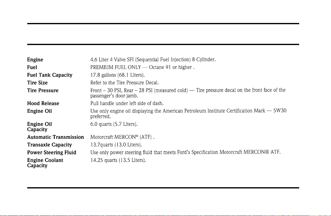
323
Service Station Information
File:17fngsc.ex
Update:Tue Sep 10 08:42:10 1996