Loading ...
Loading ...
Loading ...
US
12
Preparation
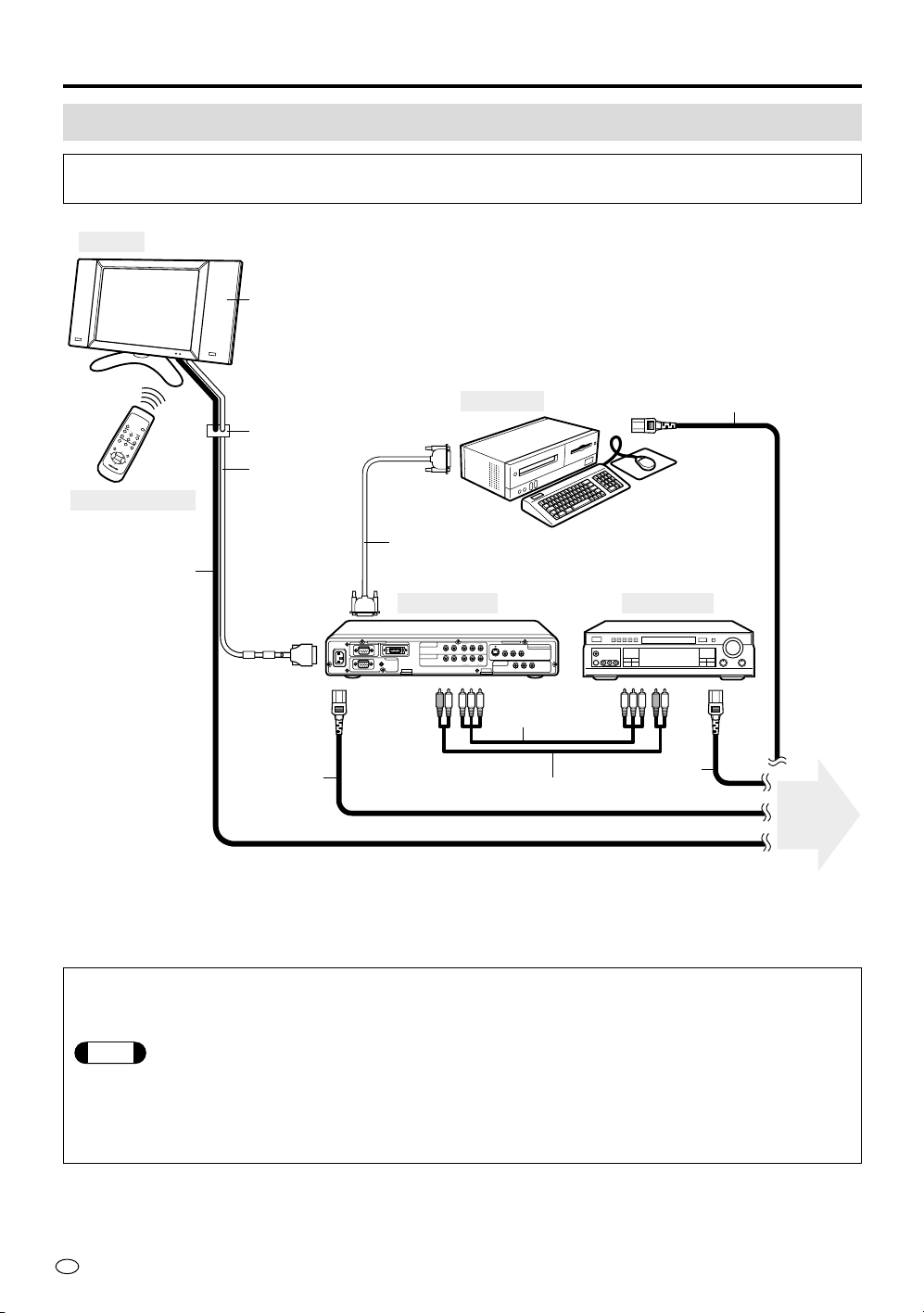
System Connection (Example)
The following diagram shows an example of system connection, on which this Operation
Manual is based.
PC INPUT
AUDIO
R-AUDIO-L
COMPONENT 1
(INPUT)
DISPLAY OUTPUTRS-232C
110-120V /
220-240V~
COMPONENT 2
(INPUT)
YP
B
(C
B
)P
R
(C
R
)
R-AUDIO-L Y P
B
(C
B
)P
R
(C
R
)
RGB
VIDEO
VIDEO
L
C
D
M
O
N
I
T
O
R
NTSC / PAL / SECAM
AV INPUT 1
S-VIDEO R-AUDIO-L
VIDEO R-AUDIO-L
AV INPUT 3
/ AV OUT
AVC System
Remote Control
Display
DVD Player
Computer
Cable Clamp
15-pin D-sub cable (*2)
Optional speaker system (*1)
System cable
AC Power cord
12ft.5-
39
/
64
" [3.8m]
AC Power cord
5ft.10-
55
/64" [1.8m]
AC Power cord
Audio Cable (*3)
AC Power cord
To power
outlet
Component
Video cable (*3)
(*1) For the best sound quality, we recommend you purchase the optional speaker system with built-in amplifier. The
optional speakers are connected to the rear cabinet of the display.
(*2) (*3) These cables are sold separately.
To enjoy the beautiful sound with optional Bose System side speakers
1 Make sure that the AV-3 setting of the OPTION mode in “OUTPUT” to “FIX” position.
Note
If it is set to “VARIABLE” position, the sound does not come out from the speakers. Change the
setting to “FIX” position so that you will be able to hear the sound. The setting procedures are shown
on page 27.
2 You can control the sound volume with VOLUME (+)/(–) on the remote control or the top of the
display.
Loading ...
Loading ...
Loading ...