LC-28HM2
OPERATION MANUAL
MODE D’EMPLOI
LC-28HM2
LCD AV MONITOR
MONITEUR AV À
CRISTAUX LIQUIDES
ENGLISH
FRANÇAIS
Printed in Japan
Imprimé au Japon
TINS-7335CEZZ
Printed on post-consumer recycled paper.
Imprimé sur du papier recyclé.
MANUAL DE MANEJO
MANUAL DE OPERAÇÃO
LC-28HM2
MONITOR AV LCD
MONITOR AV DE TELA
DE CRISTAL LÍQUIDO
ESPAÑOL
PORTUGUÊS
Impreso en papel reciclado.
Impresso em papel reciclado pós utilização.
Impreso en Japón
Impresso no Japão
TINS-7335CEZZ
1
1

Important Information
CAUTION
RISK OF ELECTRIC
SHOCK
DO NOT OPEN
CAUTION: TO REDUCE THE RISK OF ELECTRIC SHOCK,
DO NOT REMOVE COVER.
NO USER-SERVICEABLE PARTS INSIDE.
REFER SERVICING TO QUALIFIED SERVICE
PERSONNEL.
The lightning flash with arrowhead
symbol, within an equilateral triangle,
is intended to alert the user to the
presence of uninsulated “dangerous
voltage” within the product’s enclo-
sure that may be of sufficient
magnitude to constitute a risk of
electric shock to persons.
The exclamation point within a
triangle is intended to alert the user
to the presence of important operat-
ing and maintenance (servicing)
instructions in the literature accom-
panying the product.
WARNING: TO REDUCE THE RISK OF FIRE OR ELECTRIC SHOCK, DO
NOT EXPOSE THIS PRODUCT TO RAIN OR MOISTURE.
INFORMATION
This equipment has been tested and found to comply with the limits for a Class A digital device, pursuant
to Part 15 of the FCC Rules. These limits are designed to provide reasonable protection against harmful
interference in a residential installation. This equipment generates, uses, and can radiate radio frequency
energy and, if not installed and used in accordance with the instructions, may cause harmful interference to
radio communications. However, there is no guarantee that interference will not occur in a particular
installation. If this equipment does cause harmful interference to radio or television reception, which can be
determined by turning the equipment off and on, the user is encouraged to try to correct the interference by
one or more of the following measures:
• Relocate or adjust the receiving antenna.
• Increase the separation between the equipment and receiver.
• Connect the equipment into an outlet on a circuit different from that to which the receiver is connected.
• Consult the dealer or an experienced radio/TV technician for help.
U.S.A. ONLY
WARNING: FCC Regulations state that any unauthorized changes or modifications to this equipment not
expressly approved by the manufacturer could void the user’s authority to operate this equipment.
U.S.A. ONLY
CAUTION: Use the supplied AC cord as it is.
Do not remove the core part from the AC cord, and do not change
the way of winding cables around the core part.
CAUTION
Danger of explosion if battery is incorrectly replaced.
Replace only with the same or equivalent type
recommended by the manufacturer.
Dispose of used batteries according
to the manufacturer’s instructions.

ENGLISH
OPERATION MANUAL
ENGLISH
Contents
Adjusting the BRIGHT Settings ............................. 22
Adjusting the PICTURE Settings ........................... 23
Adjusting the SOUND Settings .............................. 25
Adjusting the OPTION Settings ............................. 27
Notes for Connection .................................................. 29
Connecting a DVD Video Player ............................ 29
Connecting a VCR/GAME System (AV-1 and AV-2)...
29
Connecting AV Equipment
(AV INPUT 3/ AV OUT) ............................................. 29
Connecting to a Computer ......................................... 30
Connection .............................................................. 30
Computer Control of the Display........................... 31
Commands .............................................................. 32
Computer Compatibility Chart ............................... 36
Reference ..................................................................... 37
Picture Sizes ............................................................ 37
Troubleshooting ...................................................... 39
Specifications .......................................................... 40
Dimensional Drawings ........................................... 41
Using the Wall Mount Bracket (Option) ................ 43
Safety Precautions ........................................................ 2
General Information ...................................................... 4
Supplied Accessories ............................................... 4
Optional Accessories ............................................... 4
Names of Parts .......................................................... 5
Example of Application ............................................ 8
Preparation ..................................................................... 9
Connecting the Display and AVC System............... 9
Batteries for Remote Control ................................. 11
System Connection (Example) .............................. 12
Basic Operation ........................................................... 14
Turning on POWER ................................................. 14
Switching INPUT Source ........................................ 14
Adjusting BRIGHTNESS ......................................... 15
Sound VOLUME ...................................................... 15
Adjusting the Display’s Position ........................... 16
Cleaning ................................................................... 16
Adjustments to the On-Screen Display .................... 17
Menu List ................................................................. 17
Adjusting the VIEW Settings.................................. 18
Page
Page

US
2
Dear SHARP Customer
Thank you for your purchase of a SHARP LCD product. To ensure safety and many
years of trouble-free operation of your product, please read the Safety Precautions
carefully before using this product.
Safety Precautions
Electricity is used to perform many useful functions, but it can also cause personal injuries and property
damage if improperly handled. This product has been engineered and manufactured with the highest
priority on safety. However, improper use can result in electric shock and/or fire. In order to prevent
potential danger, please observe the following instructions when installing, operating and cleaning the
product. To ensure your safety and prolong the service life of your LCD product, please read the follow-
ing precautions carefully before using the product.
1. Read instructions—All operating instructions must be read and understood before the product is
operated.
2. Keep this manual in a safe place—These safety and operating instructions must be kept in a safe
place for future reference.
3. Observe warnings—All warnings on the product and in the instructions must be observed closely.
4. Follow instructions—All operating instructions must be followed.
5. Cleaning—Unplug the power cord from the AC outlet before cleaning the product. Use a damp
cloth to clean the product. Do not use liquid cleaners or aerosol cleaners.
6. Attachments—Do not use attachments not recommended by the manufacturer. Use of inadequate
attachments can result in accidents.
7. Water and moisture—Do not use the product near water, such as bathtub, washbasin, kitchen
sink and laundry tub, swimming pool and in a wet basement.
8. Stand—Do not place the product on an unstable cart, stand, tripod or table. Placing the product
on an unstable base can cause the product to fall, resulting in serious personal injuries as well as
damage to the product. Use only a cart, stand, tripod, bracket or table recommended by the
manufacturer or sold with the product. When mounting the product on a wall, be sure to follow the
manufacturer’s instructions. Use only the mounting hardware recommended by the manufacturer.
9. When relocating the product placed on a cart, it must be moved with utmost
care. Sudden stops, excessive force and uneven floor surface can cause the
product to fall from the cart.
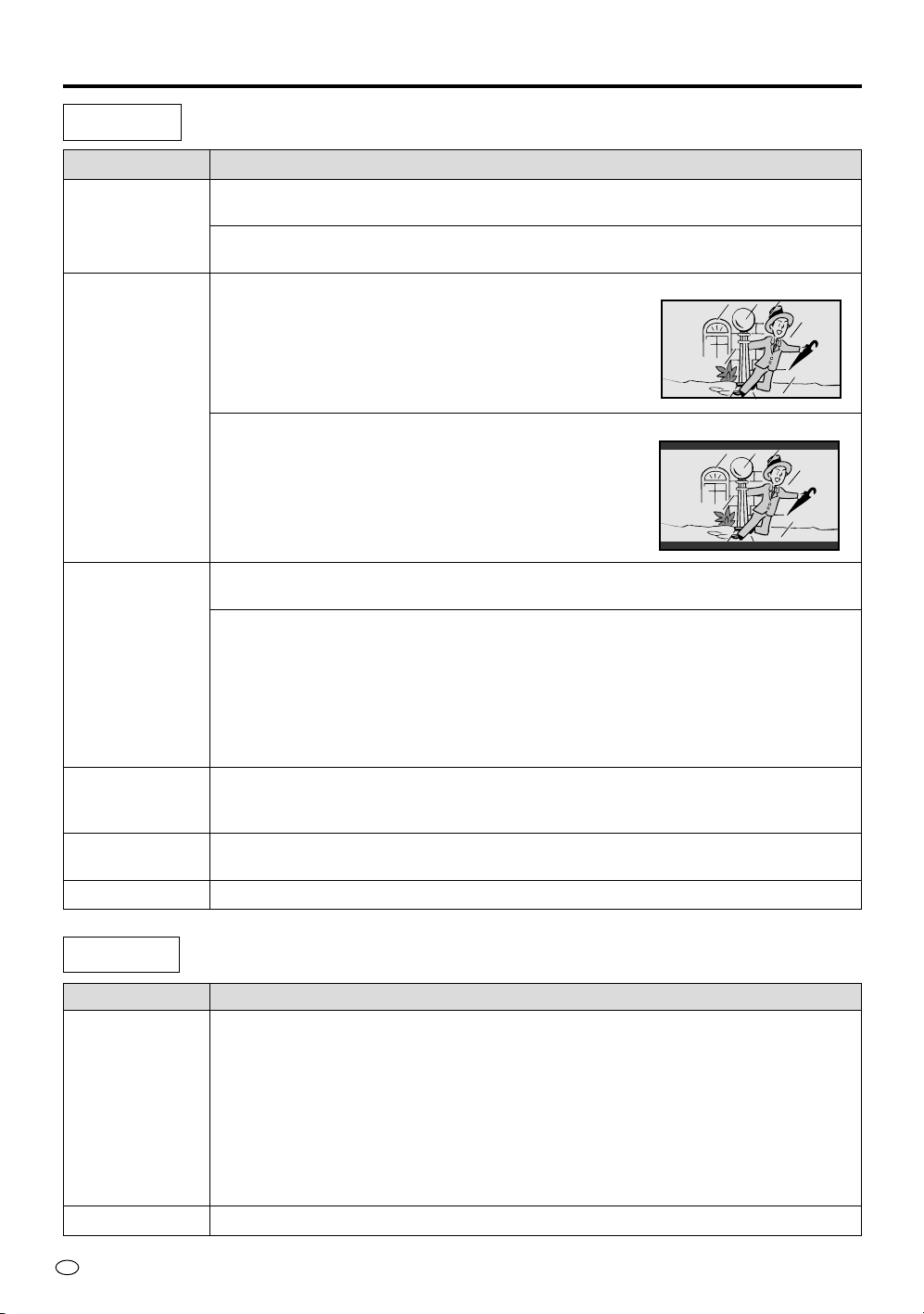
10. Ventilation—The vents and other openings in the cabinet are designed for
ventilation. Do not cover or block these vents and openings since insufficient
ventilation can cause overheating and/or shorten the life of the product. Do not
place the product on a bed, sofa, rug or other similar surface, since they can block
ventilation openings. Do not place the product in an enclosed place such as a
bookcase or rack, unless proper ventilation is provided or the manufacturer’s
instructions are followed.
11. Power cord protection—The power cords must be routed properly to prevent people from step-
ping on them or objects from resting on them.
12. The LCD panel used in this product is made of glass. Therefore, it can break when the product is
dropped or applied with impact. Be careful not to be injured by broken glass pieces in case the
LCD panel breaks.
13. Overloading—Do not overload AC outlets or extension cords. Overloading can cause fire or
electric shock.
14. Entering of objects and liquids—Never insert an object into the product through vents or open-
ings. High voltage flows in the product, and inserting an object can cause electric shock and/or
short internal parts. For the same reason, do not spill water or liquid on the product.
15. Servicing—Do not attempt to service the product yourself. Removing covers can expose you to
high voltage and other dangerous conditions. Request a qualified service person to perform
servicing.
3
US
General Information
Preparation
Basic Operation
Adjustments to the
On-Screen Display
Notes for
Connection
Reference
Connecting
to a Computer
16.Repair—If any of the following conditions occurs, unplug the power cord from the AC outlet, and
request a qualified service person to perform repairs.
a.When the power cord or plug is damaged.
b.When a liquid was spilled on the product or when objects have fallen into the product.
c. When the product has been exposed to rain or water.
d.When the product does not operate properly as described in the operating instructions.
Do not touch the controls other than those described in the operating instructions. Improper
adjustment of controls not described in the instructions can cause damage, which often re-
quires extensive adjustment work by a qualified technician.
e.When the product has been dropped or damaged.
f. When the product displays an abnormal condition. Any noticeable abnormality in the product
indicates that the product needs servicing.
17.Replacement parts—In case the product needs replacement parts, make sure that the service
person uses replacement parts specified by the manufacturer, or those with the same characteris-
tics and performance as the original parts. Use of unauthorized parts can result in fire, electric
shock and/or other danger.
18.Safety checks—Upon completion of service or repair work, request the service technician to
perform safety checks to ensure that the product is in proper operating condition.
19.Wall or ceiling mounting—When mounting the product on a wall or ceiling, be sure to install the
product according to the method recommended by the manufacturer.
20.Heat sources—Keep the product away from heat sources such as radiators, heaters, stoves and
other heat-generating products (including amplifiers).
21.Power source—This product must operate on a power source specified on the specification label.
If you are not sure of the type of power supply used in your home, consult your dealer or local
power company. For units designed to operate on batteries or another power source, refer to the
operating instructions.
The LCD panel is a very high technology product with 2,949,120 thin film transistors, giving you
fine picture details.
Occasionally, a few non-active pixels may appear on the screen as a fixed point of blue, green
or red.
Please note that this does not affect the performance of your product.
OPTIONAL
speaker
system
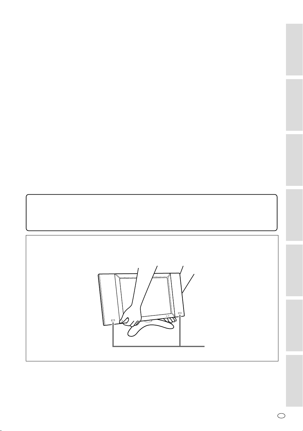
Precautions when transporting the display
When transporting the display, never carry it by holding onto the speakers. Be sure to always
carry the display by holding it with two hands-one hand on each side of the display.
US
4
General Information
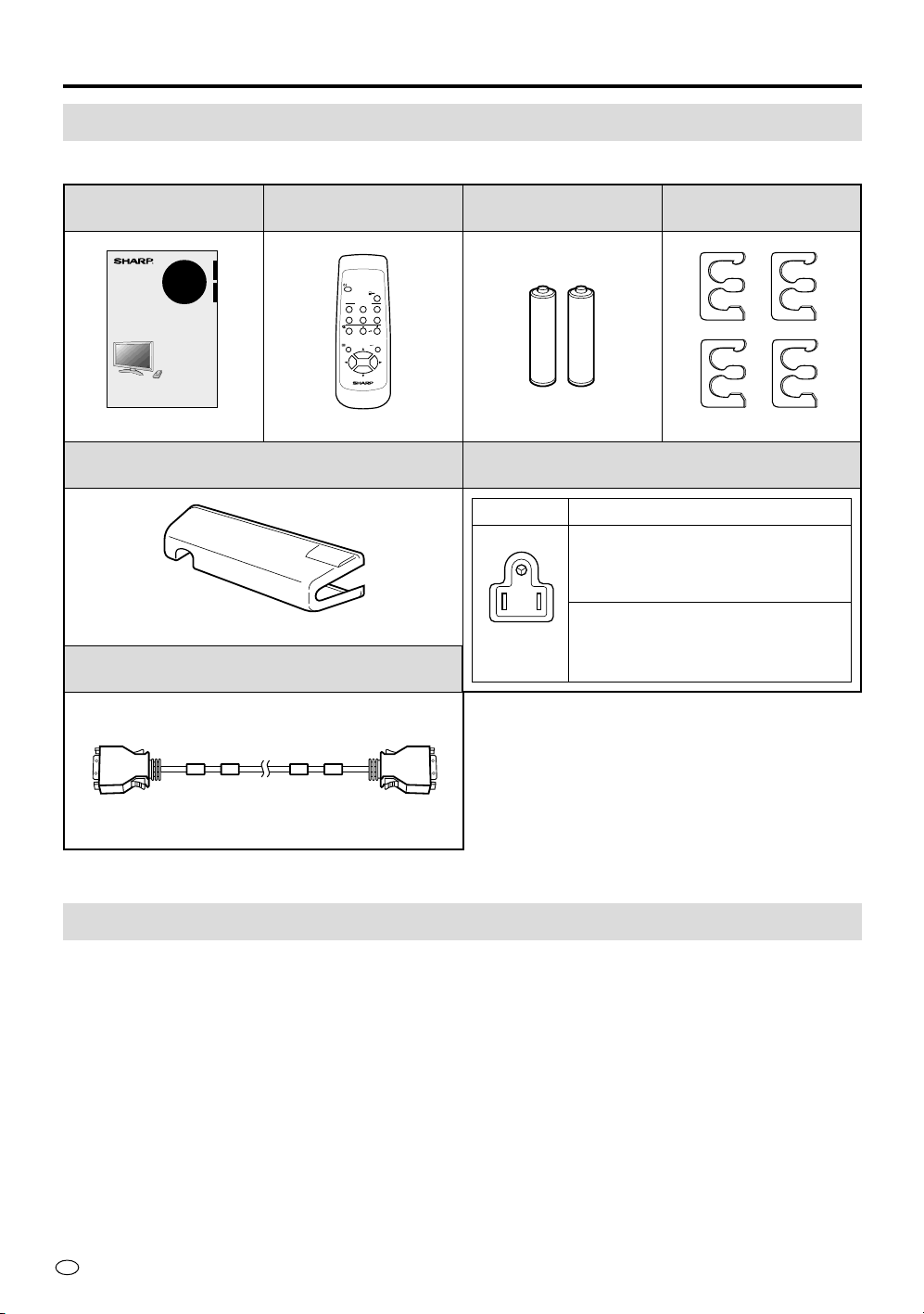
Supplied Accessories
Make sure the following accessories are provided with the product.
Remote Control
(×1)
AC Power Cord (×2)
Operation Manual (×1)
Size AA Dry Battery
(×2)
Cable Clamp (×4)
AVC System Terminal Cover (×1)
System Cable (×1)
POWER
123
12
PC
INPUT
COMPONENT
MUTE
MENU ENTER
VOL
AV INPUT
LCD MONITOR
3 pins
Plug form
Cord length
12ft.5-
39
/64" [3.8m] (for Display)
5ft.10-
55
/64" [1.8m] (for AVC system)
QACCD5023CEZZ
QACCD5024CEZZ
OPERATION MANUAL
MODE D’EMPLOI
LC-28HM2
LCD AV MONITOR
MONITEUR AV À
CRISTAUX LIQUIDES
ENGLISH
FRANÇAIS
Printed in Japan
Imprimé au Japon
TINS-XXXXCEZZ
Printed on post-consumer recycled paper.
Imprimé sur du papier recyclé.
Optional Accessories
• Bose System Side Speaker (Model: AN-28SP2)
• Wall Mount Bracket (Model: AN-28AG1)
TINS-7335CEZZ RRMCG1619CESA UBATU0243GEZZ LHLDW1224CEZZ
GCOVA1860CE02
QCNW-5948CEZZ
US
6
General Information
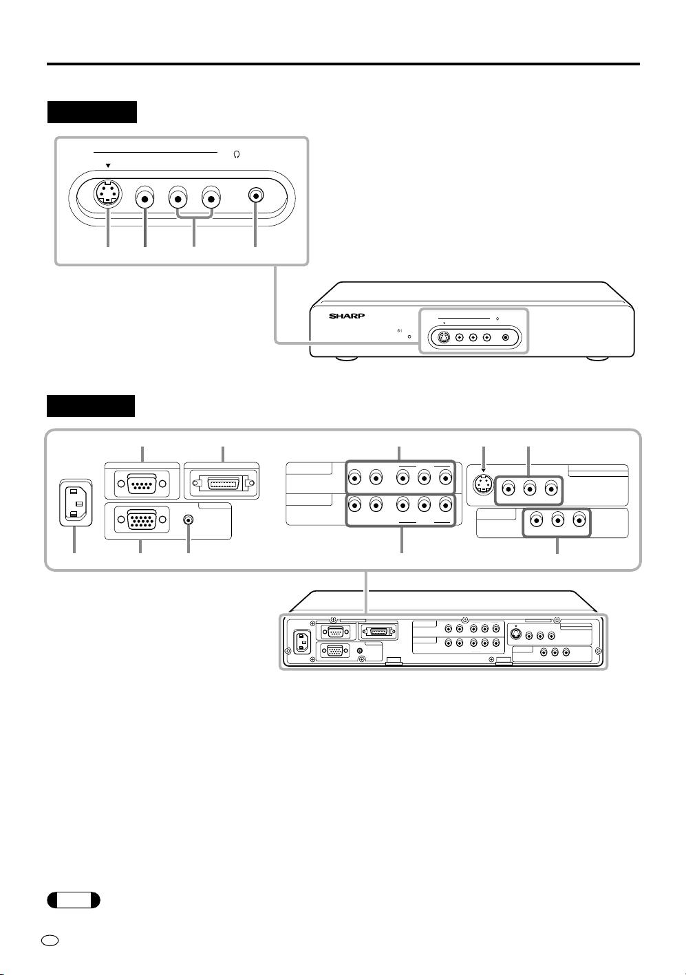
AVC System
Rear view
POWER
L- -RAUDIO
VIDEO
S-VIDEO
AV INPUT 2
AVC SYSTEM
L- -RAUDIO
VIDEO
S-VIDEO
AV INPUT 2
HEAD
PHONE
12 3 4
HEAD
PHONE
NTSC / PAL / SECAM
PC INPUT
AUDIO
AV INPUT 1
S-VIDEO VIDEO R-AUDIO-L
R-AUDIO-L
COMPONENT 1
(INPUT)
DISPLAY OUTPUTRS-232C
110-120V /
220-240V~
COMPONENT 2
(INPUT)
YP
B
(C
B
)P
R
(C
R
)
R-AUDIO-L Y P
B
(C
B
)P
R
(C
R
)
VIDEO R-AUDIO-L
AV INPUT 3
/ AV OUT
RGB
VIDEO
VIDEO
PC INPUT
AUDIO
R-AUDIO-L
COMPONENT 1
(INPUT)
DISPLAY OUTPUTRS-232C
110-120V /
220-240V~
COMPONENT 2
(INPUT)
YP
B
(C
B
)P
R
(C
R
)
R-AUDIO-L Y P
B
(C
B
)P
R
(C
R
)
RGB
VIDEO
VIDEO
NTSC / PAL / SECAM
AV INPUT 1
S-VIDEO VIDEO R-AUDIO-L
VIDEO R-AUDIO-L
AV INPUT 3
/ AV OUT
1 3 470
6
9
852
1 S-VIDEO input terminal (AV INPUT 2) [p.12]
2 VIDEO input terminal (AV INPUT 2) [p.12]
3 AUDIO input terminal (AV INPUT 2) [p.12]
4 HEAD PHONE jack [p.8]
1 AC Power input terminal [p.9]
2 RS-232C input terminal [p.31]
3 PC RGB input terminal [p.30]
4 PC AUDIO input terminal [p.30]
5 DISPLAY output terminal [p.9]
6 AUDIO/VIDEO input terminal (COMPONENT1)
[p.12]
7 AUDIO/VIDEO input terminal (COMPONENT2)
[p.12]
8 S-VIDEO input terminal (AV INPUT 1) [p.12]
9 VIDEO/AUDIO input terminal (AV INPUT 1) [p.12]
0 VIDEO/AUDIO input terminal
(AV INPUT 3/AV OUT) [pp.12, 29]
* 0 can also be used as video/audio output
terminals.
Front view
Note
If video input and S-video input are both connected to the AV-1 input and/or AV-2 input, S-video input has
priority.
7
US
General Information
POWER
123
12
PC
INPUT
COMPONENT
MUTE
MENU ENTER
VOL
AV INPUT
LCD MONITOR
1
3
4
6
8
0
q
5
7
9
2
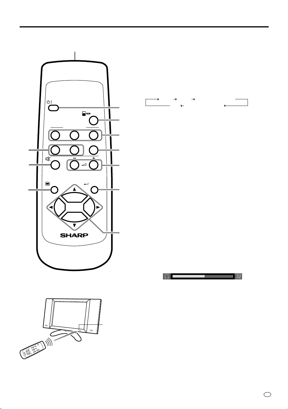
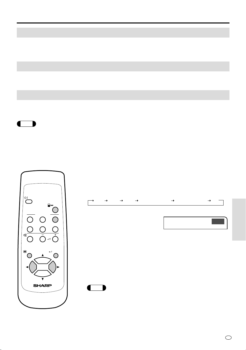
Remote Control
1 Infrared transmitter window
2 POWER button [p.14]
• To switch on the power, press this button.
The POWER/Standby indicator lights up green.
• To switch off the power, press this button.
The POWER/Standby indicator lights up red.
3 INPUT button [p.14]
Use this button to select an input source.
AV-1 AV-2 COMPONENT1
PC COMPONENT2
• The input source mode is skipped if the corre-
sponding input terminal is not connected with
external equipment (except “PC”).
• If you change the AV INPUT 3/AV OUT select,
you can select “AV-3”. See page 29 for details.
4 AV INPUT buttons
Use these buttons to select an AV input terminal
directly.
• You can not select an input source to which
external equipment is not connected.
5 COMPONENT buttons
Use these buttons to select a COMPONENT termi-
nal directly.
• You can not select an input source to which
external equipment is not connected.
6 PC button
Use this button to select the PC mode.
7 MUTE button
Use this button to temporarily turn off the sound.
Press the button again to turn the sound back to the
previous level.
8 VOL (+)/(–) buttons [p.15]
Use these buttons to increase/decrease sound volume.
The sound volume can be adjusted in the range 0~60.
9 MENU button [p.17]
Use this button to turn on/off the MENU screen.
0 ENTER button [p.18]
Use this button to execute a command.
q Cursor buttons [p.18]
Use these buttons to select a desired item on the
setting screen.
L
C
D
M
O
N
I
T
O
R
Remote Control
Display
Remote sensor
window

US
8
General Information
POWER
L- -RAUDIO
VIDEO
S-VIDEO
AV INPUT 2
AVC SYSTEM
HEAD
PHONE
L- -RAUDIO
VIDEO
S-VIDEO
AV INPUT 2
HEAD
PHONE
Example of Application
Using Headphones
You can use any pair of headphones (
9
/
64
" [3.5mm] diameter mini-plug) to listen to the sound.
Commercially available
(
9
/
64
" [3.5mm] diameter mini-jack, 16 ohms)
Indicator
Note
• When connecting headphones, the sound from the display speakers is muted.
•“ ” indicator appears when a pair of headphones is connected.
11
US
Preparation
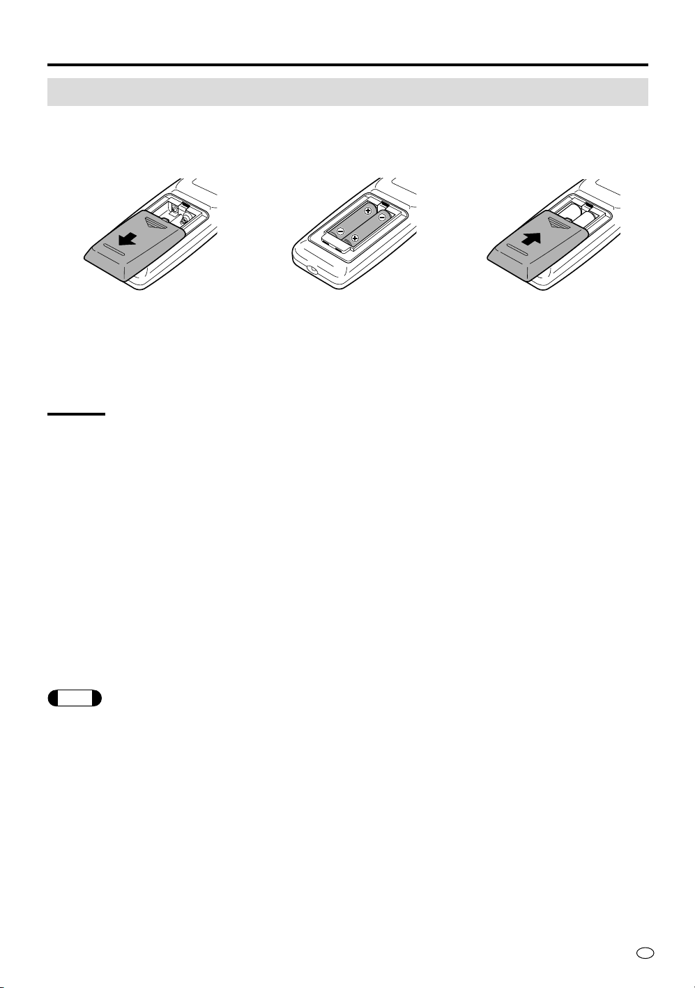
Batteries for Remote Control
If the remote control fails to operate the display, replace the batteries in the remote control.
1 Open the battery
compartment cover.
2 Load the supplied AA
batteries.
3 Close the battery
compartment cover.
• Slide the cover in the direction
of the arrow.
• Place the batteries with their
terminals corresponding to the
(+) and (–) indications in the
battery compartment.
• Slide the cover in the direction
of the arrow.
CAUTION
Battery handling precautions
Improper use of the dry batteries can result in leakage of the battery fluid and/or rupture. Be sure to
follow the guidelines outlined below.
• Place the batteries with their terminals according to the (+) and (–) locations.
• Different types of batteries have different characteristics. Do not mix batteries of different types.
• Do not use old and new batteries together. Mixing old and new batteries can shorten the life of new
batteries and/or cause old batteries to leak battery fluid.
• Remove batteries as soon as they are exhausted. Fluid leaking from the batteries can cause a rash. If
fluid has leaked out, wipe it off with a cloth.
Remote control handling precautions
• Do not expose the remote control to excessive shock. Do not place the remote control where it can
get wet or where the humidity is high.
• Do not place the remote control in a location where it is exposed to direct sunlight.
The heat can deform its plastic exterior.
• When the remote sensor window of the display is exposed to direct sunlight or to strong light source,
remote control may prove to be difficult. Change the direction of the light source or of the display or
operate the remote control from a location closer to the remote sensor window.
Note
• The batteries included with the unit may not last as long as new batteries due to aging. Replace them when they fail
to operate the remote control.
• If the remote control is not used for extended periods of time, remove the batteries.
US
12
Preparation
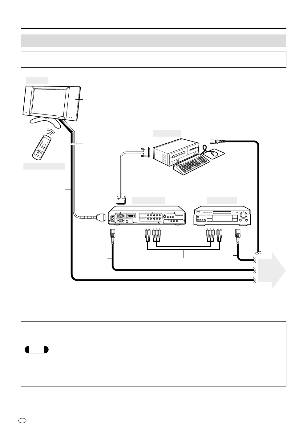
System Connection (Example)
The following diagram shows an example of system connection, on which this Operation
Manual is based.
PC INPUT
AUDIO
R-AUDIO-L
COMPONENT 1
(INPUT)
DISPLAY OUTPUTRS-232C
110-120V /
220-240V~
COMPONENT 2
(INPUT)
YP
B
(C
B
)P
R
(C
R
)
R-AUDIO-L Y P
B
(C
B
)P
R
(C
R
)
RGB
VIDEO
VIDEO
L
C
D
M
O
N
I
T
O
R
NTSC / PAL / SECAM
AV INPUT 1
S-VIDEO R-AUDIO-L
VIDEO R-AUDIO-L
AV INPUT 3
/ AV OUT
AVC System
Remote Control
Display
DVD Player
Computer
Cable Clamp
15-pin D-sub cable (*2)
Optional speaker system (*1)
System cable
AC Power cord
12ft.5-
39
/
64
" [3.8m]
AC Power cord
5ft.10-
55
/64" [1.8m]
AC Power cord
Audio Cable (*3)
AC Power cord
To power
outlet
Component
Video cable (*3)
(*1) For the best sound quality, we recommend you purchase the optional speaker system with built-in amplifier. The
optional speakers are connected to the rear cabinet of the display.
(*2) (*3) These cables are sold separately.
To enjoy the beautiful sound with optional Bose System side speakers
1 Make sure that the AV-3 setting of the OPTION mode in “OUTPUT” to “FIX” position.
Note
If it is set to “VARIABLE” position, the sound does not come out from the speakers. Change the
setting to “FIX” position so that you will be able to hear the sound. The setting procedures are shown
on page 27.
2 You can control the sound volume with VOLUME (+)/(–) on the remote control or the top of the
display.

13
US
Preparation
If you connect your audio amplifier or system speakers to the unit, please refer to the system example
below.
PC INPUT
AUDIO
R-AUDIO-L
COMPONENT 1
(INPUT)
DISPLAY OUTPUTRS-232C
110-120V /
220-240V~
COMPONENT 2
(INPUT)
YP
B
(C
B
)P
R
(C
R
)
R-AUDIO-L Y P
B
(C
B
)P
R
(C
R
)
RGB
VIDEO
VIDEO
NTSC / PAL / SECAM
AV INPUT 1
S-VIDEO R-AUDIO-L
VIDEO R-AUDIO-L
AV INPUT 3
/ AV OUT
AVC System
DisplaySpeaker Speaker
DVD Player
Amplifier
Cable Clamp
System cable
AC Power
cord
AC Power cordAudio cable
AC Power cord
Audio Cable
(Sold separately)
Sold separately
To power
outlet
Component
Video cable
Using an external speaker system
1 Connect an audio cable from the audio input terminal (LINE-IN) of the
amplifier to the AV INPUT 3/AV OUT terminal on the rear of the AVC
system.
2 Set the AV-3 setting of the OPTION mode in “OUTPUT” (VARIABLE).
See page 27 for the setting procedure.
3 Press VOLUME (+) on the top of the display or the remote control to
increase sound volume.
4 Set the maximum volume for the connected amplifier.
5 Check the volume level of the connected DVD player or VCR, then
adjust VOLUME (–) on the remote control to set the appropriate
volume.
POWER
123
12
PC
INPUT
COMPONENT
MUTE
MENU ENTER
VOL
AV INPUT
LCD MONITOR
US
14
Basic Operation
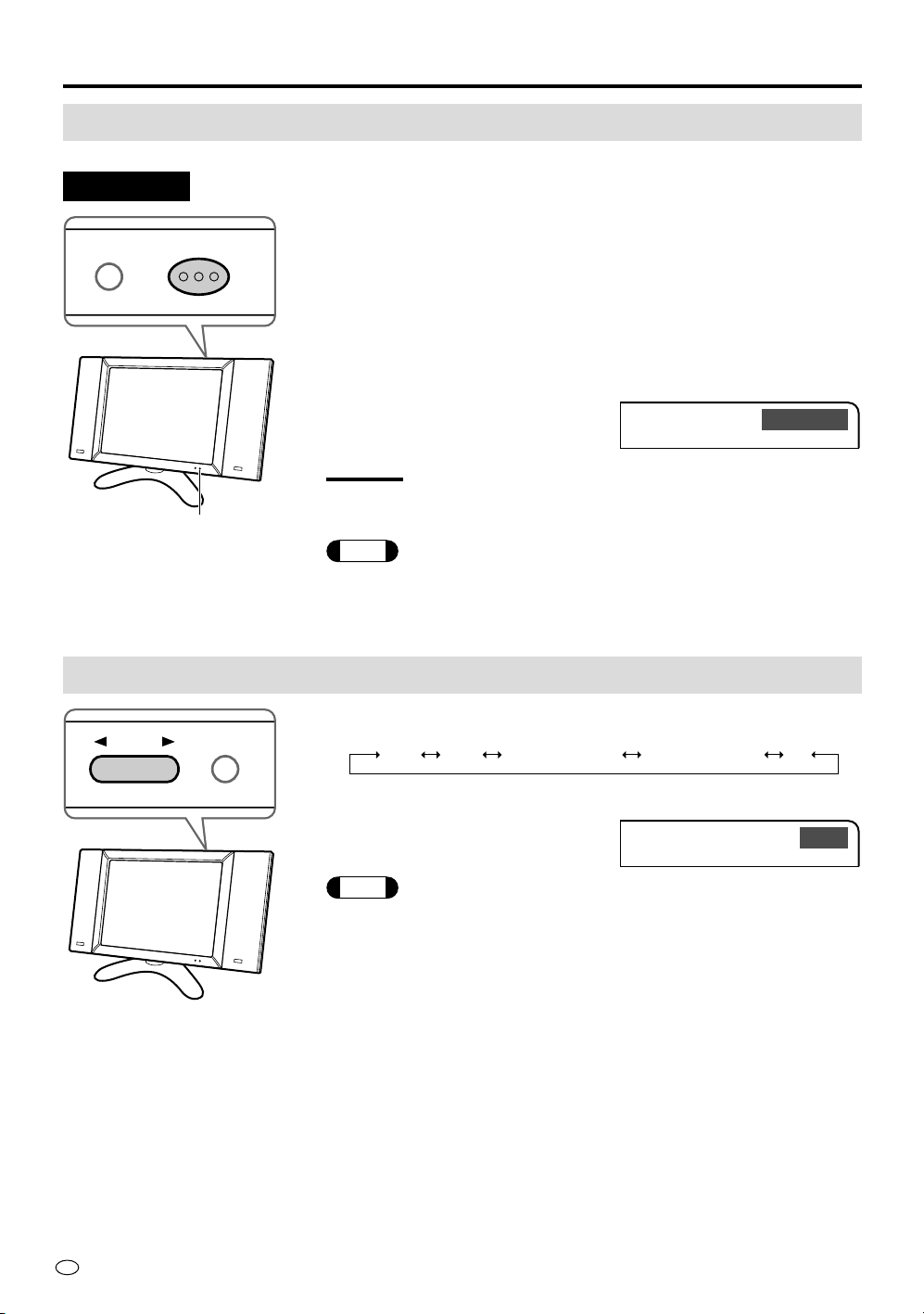
Turning on POWER
When the POWER/Standby indicator is “OFF”:
Press MAIN POWER on the top panel of the display.
If the power cannot be switched on by pressing MAIN POWER, first
press MAIN POWER in the “OFF” position, then while keeping INPUT
pressed, press MAIN POWER again.
When the POWER/Standby indicator lights up “red”:
Press POWER on the remote control.
• When the power is switched on, the POWER/Standby indicator
lights up green and a mode indicator appears on the upper right
corner of the display.
CAUTION
Never pull the plug of the power cord before you switch off the power
by using the MAIN POWER button on the top panel.
Note
Unless external AV equipment is connected, the indicator “AV-1”
appears on the display.
Switching INPUT Source
Press INPUT and select the applicable input source.
Note
•The input source mode is skipped if the corresponding input terminal is not
connected with external equipment (except “PC”).
•If you change the AV INPUT 3/AV OUT select, you can select “AV-3”. See
page 29 for details.
POWER/Standby indicator
BRIGHTNESS
MAIN POWER
Top view
BRIGHTNESS
INPUT
COMPO-1
Indicator (Example)
AV-1 AV-2 COMPONENT1 COMPONENT2 PC
AV-1
Indicator (Example)
15
US
Basic Operation
Basic Operation
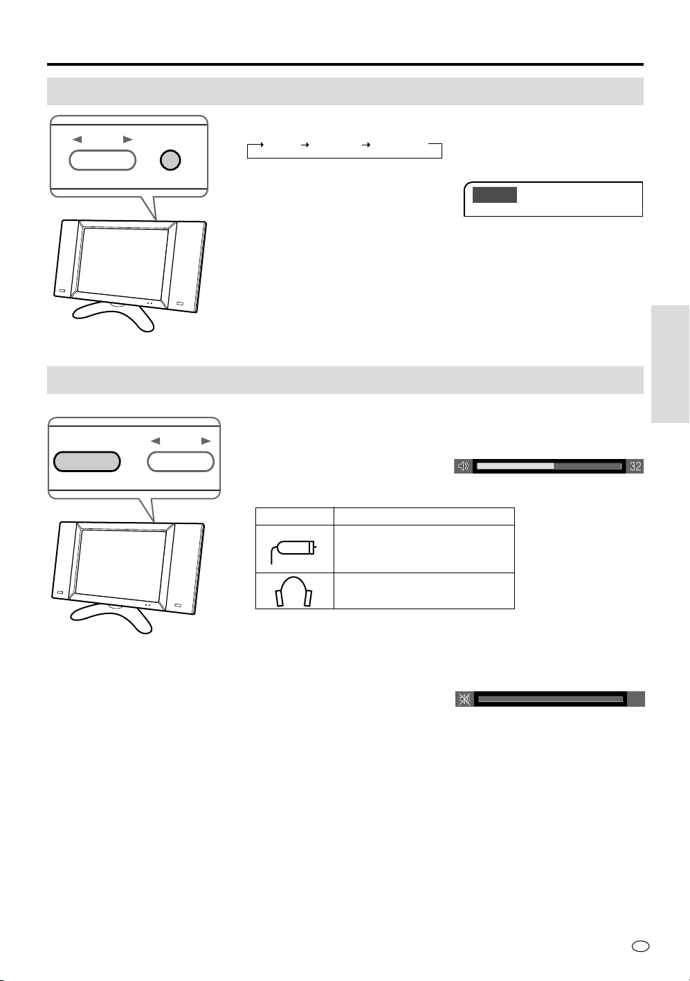
Adjusting BRIGHTNESS
Press BRIGHTNESS and adjust the brightness of the display.
DARK BRIGHT NORMAL
Sound VOLUME
Press VOL (+) to increase sound volume.
Press VOL (–) to decrease sound volume.
* No sound is output under the following conditions.
By pressing MUTE on the remote control, you can temporarily turn the
sound off.
To turn the sound on again, press MUTE once more, or VOL (+)/(–)
on the remote control or on top of the display.
BRIGHTNESS
INPUT
– +
INPUT
VOL
Indicator
Set to “Line output” with an
external amplifier connected
(page 13)
When headphones are
connected (page 8)
Mark Meaning
DARK
Indicator (Example)
Indicator
US
16
Basic Operation
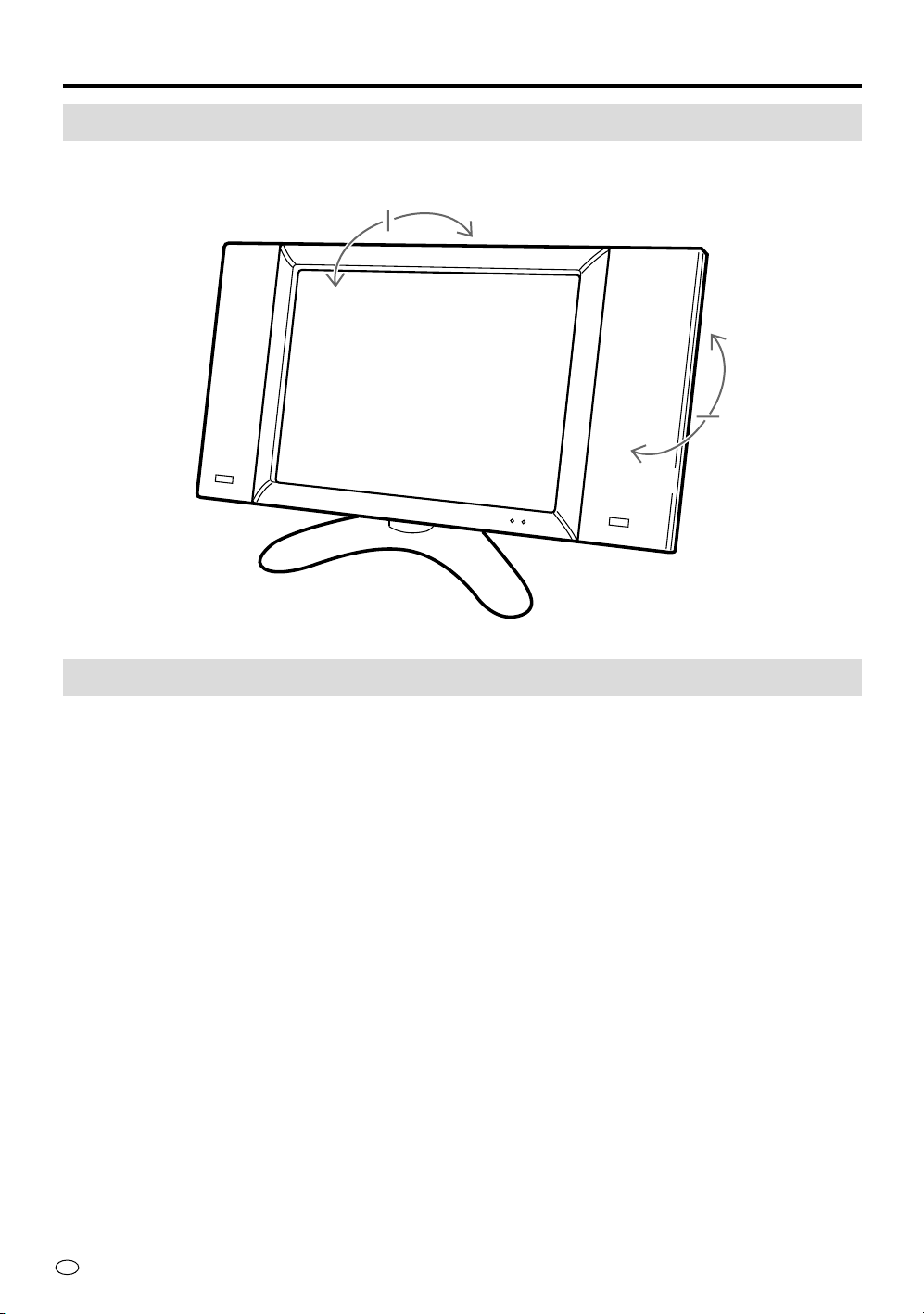
Adjusting the display’s position
The display can be inclined between 10° to the front and 8° to the back. In addition it can be rotated from
left to right and vice versa within a range of 20°.
Cleaning
Make sure to always switch the MAIN POWER button at the top of the display “OFF”, and then remove
the AC power cord.
If the screen becomes dirty, wipe it off with a damp cloth.
Taking care of the screen of your LCD display
• Never spray liquid directly on the display.
• When dust has accumulated on the screen, use a commercially available cleaning brush (anti-static
brush).
• To protect the screen, do not wipe with a dry cloth or a chemically treated cloth.
Taking care of the cabinet
• Wipe dirt off using a soft cloth made of flannel, for example.
• Never use volatile agents such as benzene or thinner as they will deteriorate the exterior and the
coating.
• Never apply other volatile chemicals such as insecticides.
Never let the exterior stay in contact with rubber or vinyl surfaces for long periods of time. This could
cause the cabinet to deteriorate or the coating to peel off.
10°
8°
10°
10°
17
US
Adjustments to the On-Screen Display
Menu List
The list below shows all the items you can set and adjust. See the following pages for details on each
setup procedure.
AV Mode
VIEW (p.18)
BRIGHT. (p.22)
PICTURE (p.23)
SOUND (p.25)
OPTION (p.27)
SIDE BAR
CINEMA
WIDE
BRIGHT
NORMAL
DARK
NORMAL
MOVIE
GAME
NORMAL
MOVIE
GAME
IMAGE
WIDE VIEW
AV-3
C-SYSTEM
DISPLAY
RESET
:Factory setting
SIDE BAR
CINEMA
FULL
DOT BY DOT
BRIGHT
NORMAL
DARK
CONTRAST
BRIGHT
RED
BLUE
RESET
TREBLE
BASS
BALANCE
LOUDNESS
RESET
IMAGE
AUTO SYNC
AV-3
SIGNAL INFO
DISPLAY
RESET
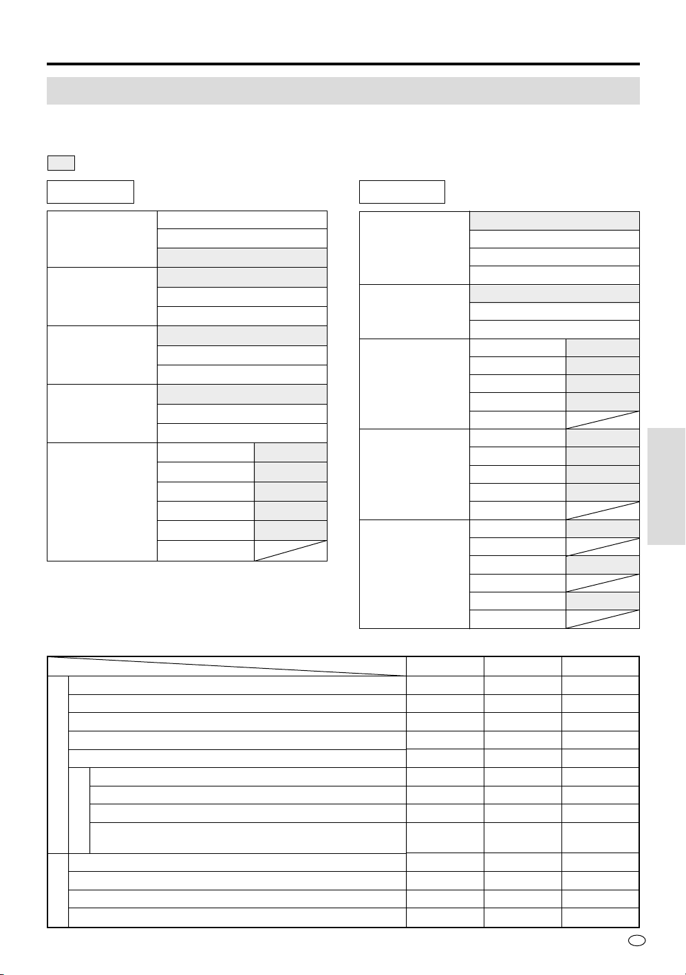
PC Mode
AV Mode Factory Setting Details
CONTRAST
TINT
COLOR
BRIGHT. (Black level)
SHARP (SHARPness)
BLACK (Black stretching: sense of depth)
VDE (Vertical Detail Enhancement) *Only for N358
F-TONE (Flesh Tone)
C-TEMP (Color TEMPerature)
*Only for PAL/PAL-60/PAL-M
TREBLE
BASS
BALANCE
LOUDNESS
PRO.
PICTURE
SOUND
NORMAL
60
0
0
0
0
OFF
OFF
ON
0
0
0
0
OFF
MOVIE
50
0
0
–5
0
OFF
OFF
ON
0
0
0
0
OFF
GAME
45
0
0
0
–20
OFF
OFF
OFF
0
0
0
0
OFF
NORMAL
FULL
OUTPUT
AUTO
ON
+30
0
0
0
0
0
0
OFF
NORMAL
OUTPUT
ON
Adjustments to the
On-Screen Display
VIEW (p.18)
BRIGHT. (p.22)
PICTURE (p.23)
SOUND (p.25)
OPTION (p.27)
US
18
–30
+
30
+
1
V-POSI.
–30
+
30
0
H-POSI.
RESE
T
V-POSI.
SIDE BAR
WI
D
CINEMA
MENU
VIEW
BRIGHT
H-POSI.
RESET
V-POSI.
SIDE BAR
WIDE
CINEMA
NU
VIEW
BRIGHT
SIDE BAR
WIDE
CINEMA
SIDE BAR
NU
VIEW
BRIGHT
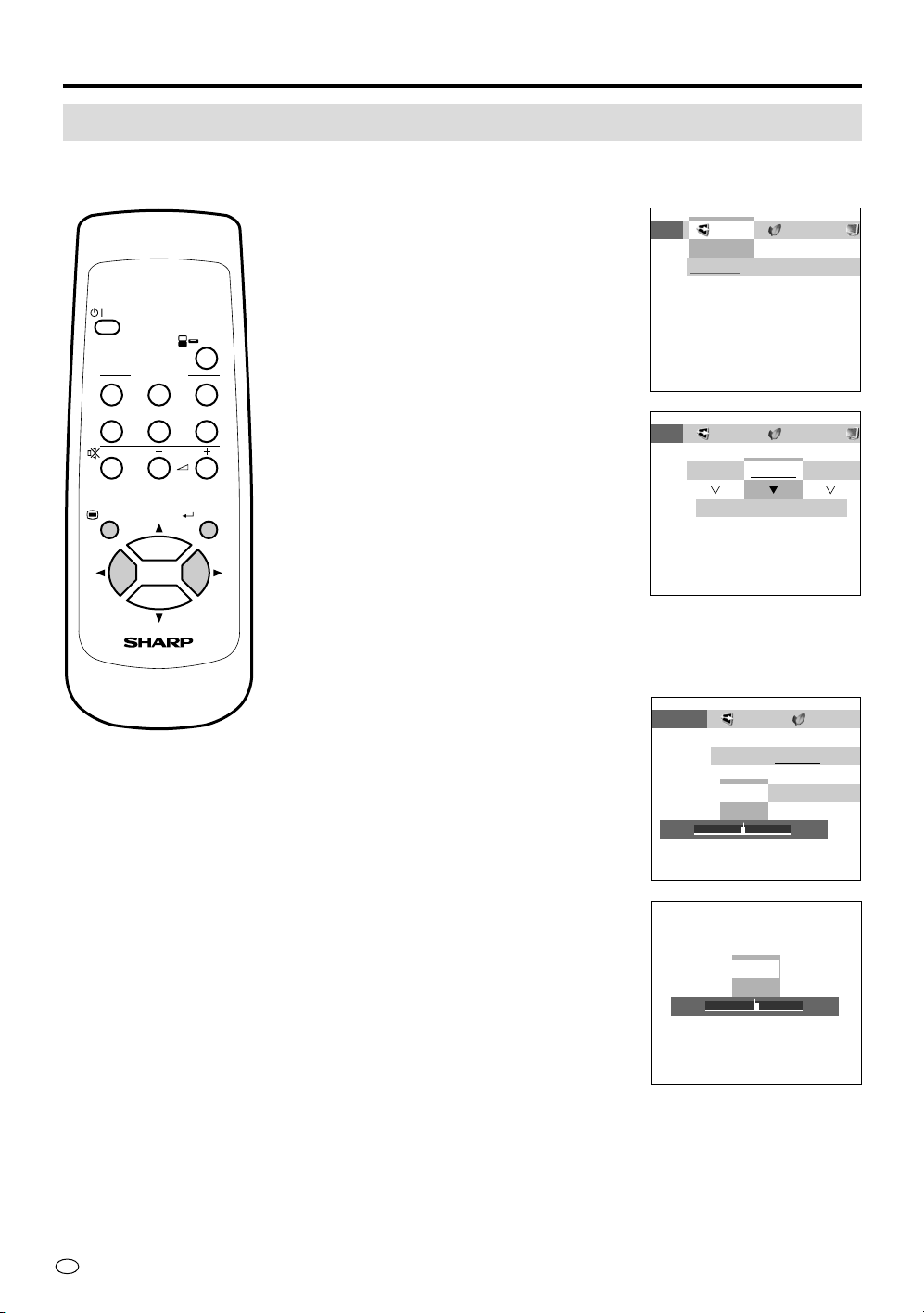
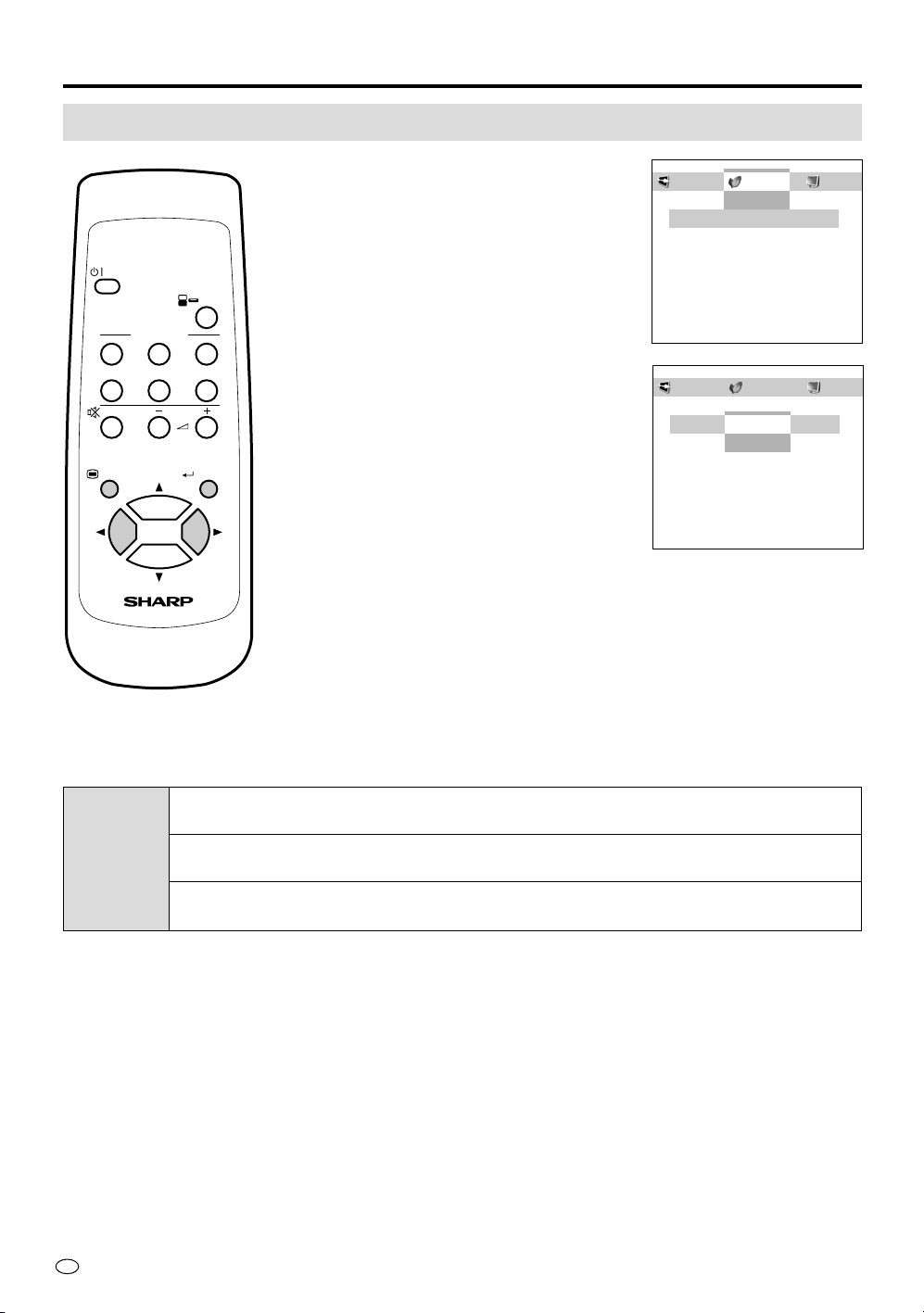
Adjusting the VIEW Settings
This menu allows you to select a picture size manually.
Details of modes and adjustment items are described on the following pages.
1 Press MENU to display the Menu screen.
Press \| to move the cursor to VIEW
and then press ENTER.
2 Press \| to move the cursor and select
the desired mode.
Then press ENTER.
Adjusting the Position of the Picture
Continue the following procedure if you want to adjust the position
vertically/horizontally.
3 Press \| to move the cursor and select
the desired adjustment.
Then press ENTER.
4 Press \| to make the adjustment and
then press ENTER.
Adjustments to the On-Screen Display
POWER
123
12
PC
INPUT
COMPONENT
MUTE
MENU ENTER
VOL
AV INPUT
LCD MONITOR

19
US
Adjustments to the On-Screen Display
Note
The SIDE BAR mode and the WIDE mode has an AUTO setting that automatically sets pictures with letter
box signals to a suitable size (for NTSC only). Please select “ON” in the AUTO setting using the '"\ |
buttons. See page 37.
AV mode
Mode
SIDE BAR
CINEMA
WIDE
➜
Hello, How are you?
➜
Hello, How are you?
The screen shows
the regular display
(height:width ratio is
4:3).
The screen shows a
movie size display
for (software-driven)
movies.
Compressed to the
4:3 format, a video
image is shown full
size.
PC mode
Mode
FULL
DOT BY DOT
Widened picture to full-screen size
Picking out the display mode of the input signal of the connected computer, this
function displays the picture in the center without enlargement.
• This unit is compatible with the following display modes.
Horizontal dot
640
800
1024
Vertical dot
480
600
768
Regular TV display
Display with bands at the top and bottom
Display with subtitles at the bottom
;;
;;
9 : 0 0
;;
;;
9 : 0 0
➜
US
20
Adjustments to the On-Screen Display
AV mode
Mode
SIDE BAR
CINEMA
WIDE
Selected item
[AUTO]
Automatically sets to a suitable
picture size
[POSITION]
Manually set to a desired position
[V-POSI.]
[H-POSI.]
[RESET]
[AUTO]
Automatically sets to a suitable
picture size
[POSITION]
Manually set to a desired position
Setting
“ON”
“OFF”
“V” Shifting the picture vertically (–10~+10)
“H” Shifting the picture horizontally (–30~+30)
“RESET” Returning to the factory setting
Shifting the picture vertically (–30~+30)
Shifting the picture horizontally (–30~+30)
Returning to the factory setting
“ON”
“OFF”
“V” Shifting the picture vertically (–15~+15)
“H” Shifting the picture horizontally (–30~+30)
“RESET” Returning to the factory setting
PC mode
Mode
SIDE BAR
CINEMA
FULL
DOT BY DOT
Selected item
[CLOCK]
[PHASE]
[V-POSI.]
[H-POSI.]
[RESET]
Setting
Adjust when flicker in the form of vertical
stripes appears. (–90~+90)
Adjust if contrast can not be obtained or flicker
occurs when letters, etc. are displayed.
(–20~+20)
Adjust when the picture is too high or too low.
(–60~+60)
Adjust when the picture is too far to the right or
too far to the left. (–90~+90)
Returning to the factory setting
* “Clock” and “PHASE” will only be displayed during the PC mode.

21
US
Note
• The screen size is slightly different when receiving 1080i signals and other type of signals.
• When the AUTO setting is “ON”, the picture may become larger and smaller, but this is only because the AUTO
setting is automatically selecting the most appropriate image for the incoming video signal and does not indicate a
malfunction. If it is disturbing, please set the AUTO setting to “OFF” and select the appropriate picture size.
• Depending on the picture you are watching the time it takes for the selection to take place may differ.
• For wide picture signals (cinema size, etc.), black bands at the top and bottom of the screen may remain.
• When watching special playback functions (video search, slow playback, etc.) on the VCR, the AUTO setting may
stop operating.
• This unit is equipped with functions, which select appropriate picture mode for all types. Note that if a size mode is
selected that differs from the video display ratio of the software, the view will be different from the original picture.
• When watching a 4:3 format (SIDE BAR) picture adjusted to a full size using the VIEW mode, the peripheral picture
may be invisible or partly deformed. In order to watch the original picture as intended by the copyright holder; please
watch using the SIDE BAR mode.
• Depending on the signal received or the movie software, correct operation cannot be obtained with the AUTO setting.
In this case, after setting the AUTO setting of the VIEW mode to “OFF”, select the appropriate picture size.
• When displaying with the CINEMA mode during the PC mode, the picture will be shown with the top and bottom of
the parts cut off.
• When displaying a wide movie from the DVD with the PC mode, use the CINEMA mode.
• Depending on the type of commercial software, parts of subtitles, etc. may disappear. In this case, please select an
appropriate picture mode using the VIEW mode and adjust the vertical position using position adjustment. Noise and
bending of the picture may occur at the top or the edges of the picture but this does not indicate a malfunction.
• Depending on the picture displayed, the display position may not change even though the value of the adjustment
changes.
Adjustments to the On-Screen Display
US
22
BRIGHT
DARK
NORMAL
PICTUR
VIEW
BRIGHT
BRIGHT
DARK
NORMAL
BRIGHT
PICTUR
VIEW
BRIGHT
Adjusting the BRIGHT Settings
1
Press MENU to display the Menu screen.
Press \| to move the cursor to BRIGHT
and then press ENTER.
2 Press \| to make the adjustment.
Then press ENTER.
Adjustments to the On-Screen Display
BRIGHT
Maximum brightness
NORMAL
Brightness 60% ➞ Suitable for viewing in well-lit areas. Saves energy.
DARK
Brightness 20% ➞ Sufficiently bright when viewing in dim areas.
Mode
POWER
123
12
PC
INPUT
COMPONENT
MUTE
MENU ENTER
VOL
AV INPUT
LCD MONITOR
23
US
ON
OFF
ON
OFF
ON
BLACK
F-TONE C-
T
VDE
UR
RESET
BRIGHT. SHARP
MOVIE
A
L GAME
PICTURE SOUND OPTI
O
VDE F-TONE C-TEMP
RESET
RESET
SHARP PRO.
A
ME
SOUND OPTION
GAME
MOVIE
NORMAL
NORMAL
PICTURE SOUND
BRIGHT
Adjustments to the On-Screen Display
POWER
123
12
PC
INPUT
COMPONENT
MUTE
MENU ENTER
VOL
AV INPUT
LCD MONITOR
COLOR
N
T BRIGHT. SHARP
MOVIE
NORMAL
GAME
PICTURE SOUND
BRIGHT
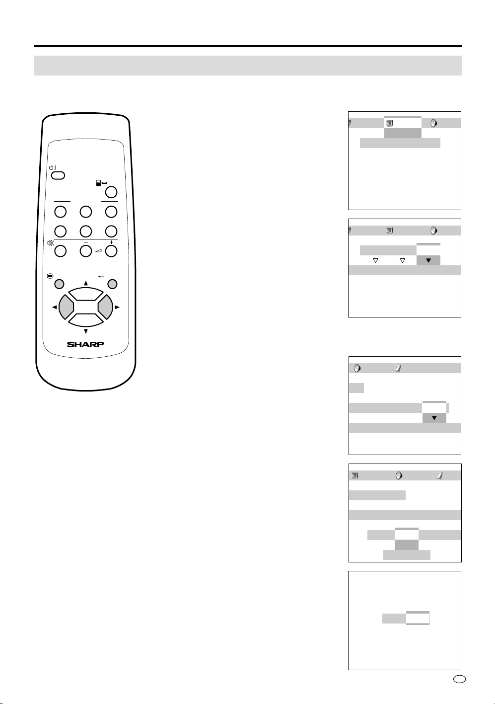
Adjusting the PICTURE Settings
This menu allows you to select an appropriate position for contents of the picture or lighting of the place.
Details of modes and adjustment items are described on the following pages.
1 Press MENU to display the Menu screen.
Press \| to move the cursor to
PICTURE and then press ENTER.
2 Press \| to move the cursor and select
the desired mode.
Then press ENTER.
For Fine Picture Adjustment
Continue the following procedure if you want to adjust the picture item by item.
3 Press \| to move the cursor and select
the desired adjustment.
Then press ENTER.
4 Press \| to move the cursor and select
the desired adjustment. Then press
ENTER.
5 Press \| to make the adjustment and
then press ENTER.
US
24
NORMAL
Suitable for viewing a most program material
MOVIE
Suitable for viewing a movie
GAME
Suitable for playing a TV game
Mode
CONTRAST
Adjusting the contrast of the picture
BRIGHT
Adjusting the black level of the picture
RED
Adjusting the red level of the picture
BLUE
Adjusting the blue level of the picture
RESET
Returning to the factory setting
Mode
AV mode
PC mode
Selected item
[CONTRAST]
[TINT]
[COLOR]
[BRIGHT]
[SHARP]
[RESET]
[PRO.]
Setting
Decrease/Increase contrast (0~+60)
Toward purple/Toward green (–30~+30)
Lower/Higher color intensity (–30~+30)
Adjusting the black level (–30~+30)
Adjusting the sharpness (–30~+30)
Returning to the factory setting
“BLACK” Adjusts the degree of dark portions of the picture and
changes the depth. (OFF/HIGH/LOW)
“VDE” Switches on/off the degree of emphasis on the contours of
the picture in the vertical direction. (ON/OFF)
Please use when picture is soft.
*Only for N358 regular video signal
“F-TONE” Changes the degree of emphasis on the skin color. (ON/
OFF)
“C-TEMP” Decrease/Increase color temperature (–5~+5)
*Only for PAL/PAL-60/PAL-M regular video signal
“RESET” Returning to the factory setting
Selected item
[CONTRAST]
[BRIGHT]
[RED]
[BLUE]
[RESET]
Setting
Decrease/Increase contrast (0~+60)
Less/More bright (–30~+30)
Less/More red level (–30~+30)
Less/More blue level (–30~+30)
Returning to the factory setting
Adjustments to the On-Screen Display
25
US
OFF
ON
OFF
ON
OFF
S
RESET
BALANCE LOUDNESS
MOVIE
GAME
SOUND OPTION
BASSTREBLE BALANCE LOUD
MOVIE
NORMAL
GAME
PICTURE SOUND OPTIO
N
GAME
MOVIE
NORMAL
NORMAL
PICTURE SOUND OPTIO
N
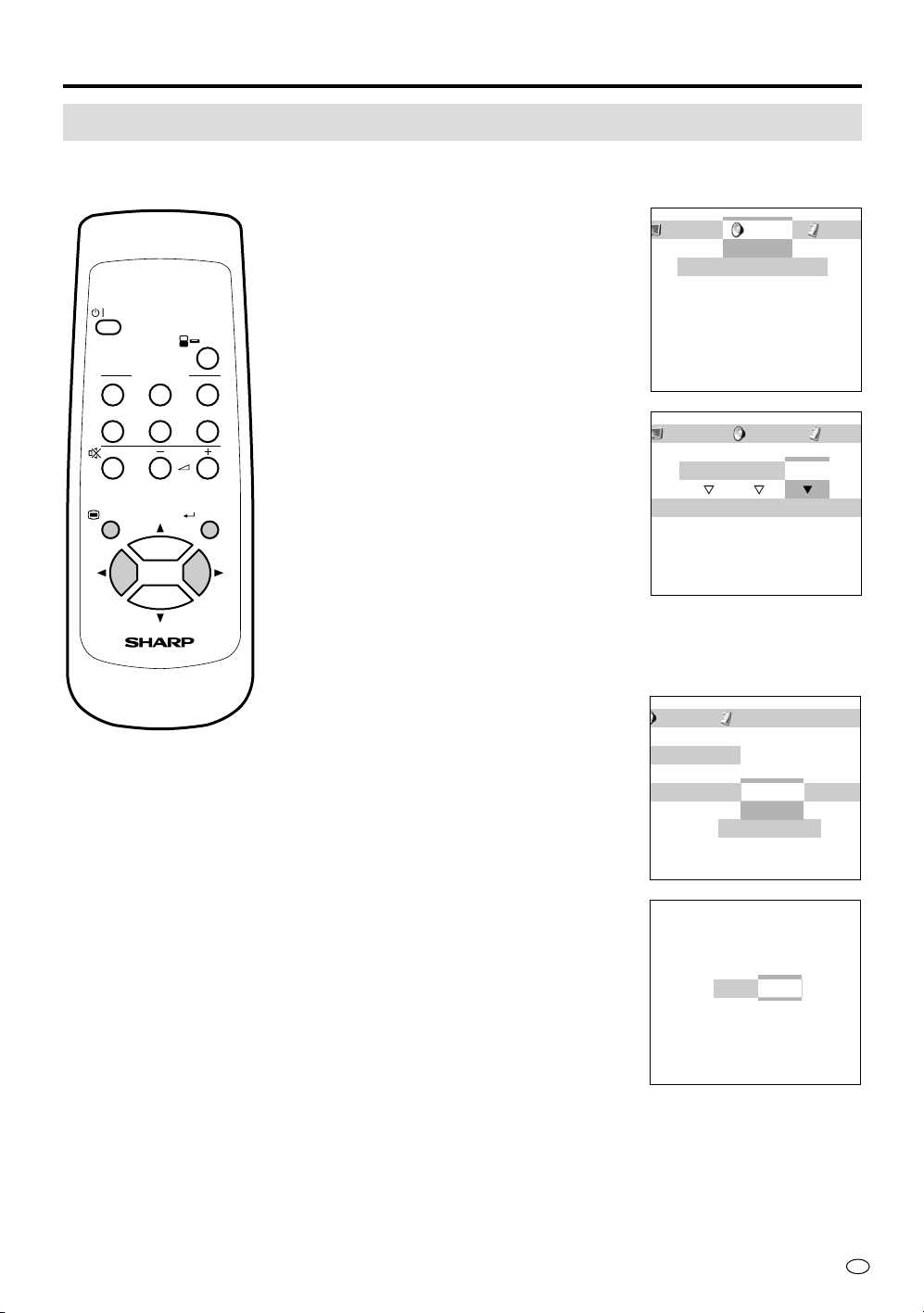
Adjusting the SOUND Settings
This menu allows you to select an appropriate position for contents of the picture.
Details of modes and adjustment items are described on the following pages.
1 Press MENU to display the Menu screen.
Press \| to move the cursor to SOUND
and then press ENTER.
2 Press \| to move the cursor and select
the desired mode.
Then press ENTER.
For Fine Sound Adjustment
Continue the following procedure if you want to adjust the sound item by
item.
3 Press \| to move the cursor and select
the desired adjustment.
Then press ENTER.
4 Press \| to make the adjustment and
then press ENTER.
POWER
123
12
PC
INPUT
COMPONENT
MUTE
MENU ENTER
VOL
AV INPUT
LCD MONITOR
Adjustments to the On-Screen Display
US
26
NORMAL
Suitable for viewing a most program material
MOVIE
Suitable for viewing a movie
GAME
Suitable for playing a TV game
Mode
AV mode
TREBLE
Decrease/Increase treble level (–30~+30)
BASS
Decrease/Increase bass level (–30~+30)
BALANCE
Adjusts the balance of right and left sound. L30 is from the most left and R30 is from the
most right.
LOUDNESS
Modulation of the sound ON/OFF
RESET
Returning to the factory setting
Mode
PC mode
Selected item
[TREBLE]
[BASS]
[BALANCE]
[LOUDNESS]
[RESET]
Setting
Decrease/Increase treble level (–30~+30)
Decrease/Increase bass level (–30~+30)
Adjusts the balance of right and left sound. L30 is from the most left
and R30 is from the most right.
Modulation of the sound ON/OFF
Returning to the factory setting
Adjustments to the On-Screen Display
US
28
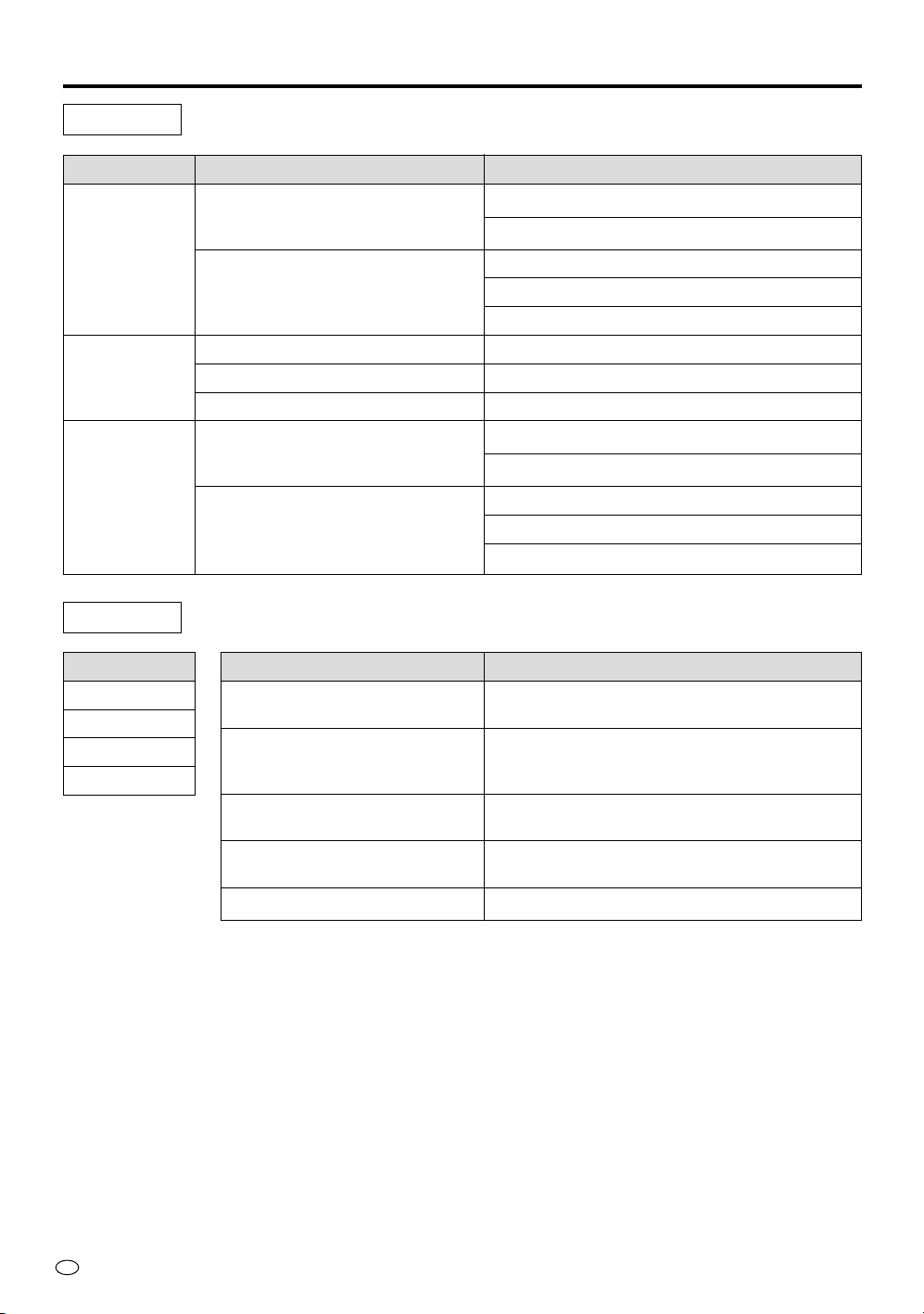
AV mode
Mode
IMAGE
WIDEVIEW
(See page 38.)
AV-3
C-SYSTEM
DISPLAY
RESET
Selected item
[NORMAL]
Normal horizontal picture orientation
[MIRROR]
Mirror image ➞ To display mirror picture for special uses.
[FULL]
This mode displays the full screen of the video signal
received. (The picture is displayed slightly stretched
vertically.)
[STRETCH]
This mode displays pictures based on the width of the
screen. Bands are present at the top and bottom.
(Aspect ratio is 16:9)
[INPUT]
AV INPUT 3 put in input mode
[OUTPUT]
The current image and sound are output from AV INPUT 3/AV OUT terminal, when
switching to “OUTPUT”.
“FIXED”: The sound level is fixed. ➞ Adjust it from the connected AV device (e.g.
an amplifier)
“VARIABLE”: The sound level is not fixed. (The maximum level is as much as in
the FIXED setting)
*No sound from side speakers
[AUTO]/[N358]/[N443]/[PAL]/[PAL-60]/[PAL-M]/[SECAM]
*The settings are stored per connection terminal (AV-1/2/3). Even if the power to
the unit is cut off, the settings will remain in the memory.
Turns [ON] or [OFF] the channel indicators which are displayed when changing
channels.
Returning to the factory setting
PC mode
Mode
AUTO SYNC
SIGNAL INFO
Selected item
Using this function, a stable computer screen without flicker in the display can be
obtained.
Press ENTER for adjustment.
*Depending on the signal, the AUTO SYNC function may not provide enough
adjustment. In this case, perform fine adjustment manually.
Even if the output setting is the same at the computer side (e.g. XGA), slight
discrepancies may occur in the adjustment of the hardware.
*Canceling the AUTO SYNC function:
Press ENTER to cancel the above function, when “Adjusting the image” is being
displayed.
This measures and sets the frequency when the display is used as a computer monitor.
Adjustments to the On-Screen Display
29
US
Connecting a DVD Video Player
When connecting a DVD player, always connect it directly to this unit.
If the signals is input via a video deck, the picture may not be displayed properly.
Connecting a VCR/GAME System (AV-1 and AV-2)
When connecting game system: “Shooting games” played with a pistol cannot be used.
Connecting AV Equipment (AV INPUT 3/ AV OUT)
• You can output the video and audio signals of AV-1/2 from the AV INPUT 3/AV OUT terminal.
• Set AV-3 setting to “OUTPUT”, and connect the AV INPUT 3/OUT terminal to an input terminal of a
video equipment, and you can record the received video and audio signal on the video equipment.
Note
•Component input signals and PC input signals are disabled for monitor output (recording).
•When using AV-1 or AV-2 with S-video input signal and the AV INPUT 3/AV OUT terminal is set to “OUTPUT”, the
signal is converted to a regular video signal output from AV OUT.
Switching the AV INPUT/OUTPUT
Changing “OUTPUT” to “INPUT”
1 Set the AV-3 setting in the OPTION mode to “INPUT”. For the opera-
tion, refer to “Adjusting the OPTION Settings” (page 27).
2 Select “AV-3” for the input source by using either the INPUT button or
the AV INPUT buttons.
AV-1 AV-2 AV-3 COMPONENT1 COMPONENT2 PC
Changing “INPUT” to “OUTPUT”
* Select the input source other than “AV-3” before going to the OPTION
mode to perform Step 1.
1 Set the AV-3 setting in the OPTION mode to “OUTPUT”.
For the operation, refer to “Adjusting the OPTION Settings” (page 27).
2 Select “FIXED” (for the optional side speakers) or “VARIABLE” (for a
commercially available speaker system).
Note
• FIXED: The sound level of the AV OUT is fixed and you can not adjust the
volume using the VOLUME buttons of the unit. Adjust the volume from the
AV equipment that is connected to the unit.
• VARIABLE: The sound level of the AV OUT is variable so that you can use
the VOLUME buttons of the unit to adjust the volume. Note that the sound
from the optional side speakers connected to the unit is muted.
• The default setting is “VARIABLE”.
Notes for Connection
POWER
123
12
PC
INPUT
COMPONENT
MUTE
MENU ENTER
VOL
AV INPUT
LCD MONITOR
AV-3
Indicator
Notes for
Connection
31
US
Connecting to a Computer
Computer Control of the Display
• When a program is set, the display can be controlled from the computer using the RS-232C terminal.
The input signal (computer/video) can be selected, the volume can be adjusted and various other
adjustments and settings can be made, enabling automatic programmed playing.
• Attach an RS-232C cable cross-type (commercially available) to the supplied Din-D/sub RS-232C for
the connections.
Note
This operation system should be used by a person who is accustomed to using computers.
Communication conditions
Set the RS-232C communications settings on the computer to match the display’s communications
conditions.
The display’s communications settings are as follows:
Communication procedure
Send the control commands from the computer via the RS-232C connector.
The display operates according to the received command and sends a response message to the compu-
ter.
Do not send multiple commands at the same time. Wait until the computer receives the OK response
before sending the next command.
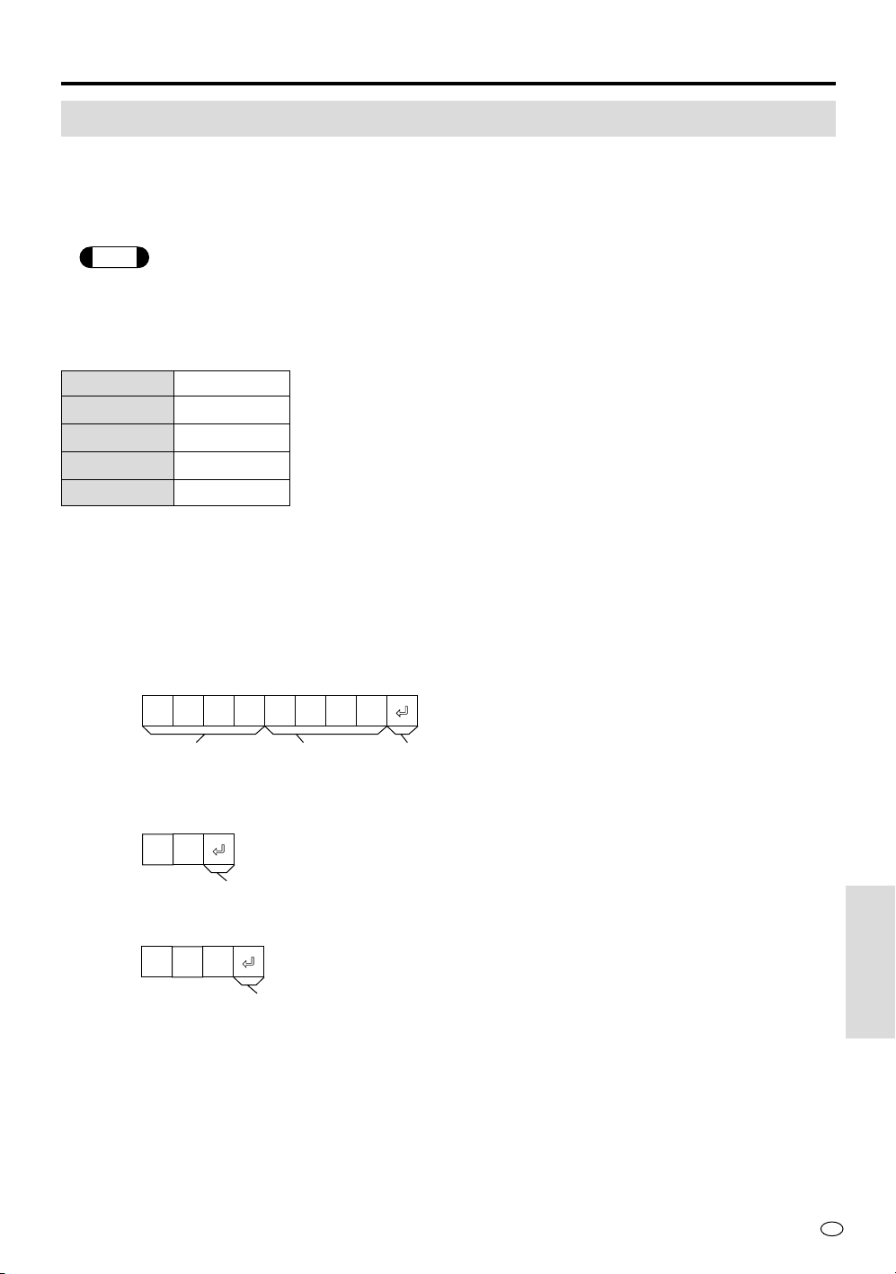
Command format
Response code format
Normal response
Problem response (communication error or incorrect command)
Baud rate 9,600 bps
Data length 8 bits
Parity bit None
Stop bit 1 bit
Flow control None
Parameter 4-digits
C1 C2 C3 C4 P1 P2 P3 P4
O K
RE R
Command 4-digits
Return code (0DH)
Return code (0DH)
Return code (0DH)
Connecting
to a Computer

US
32
Connecting to a Computer
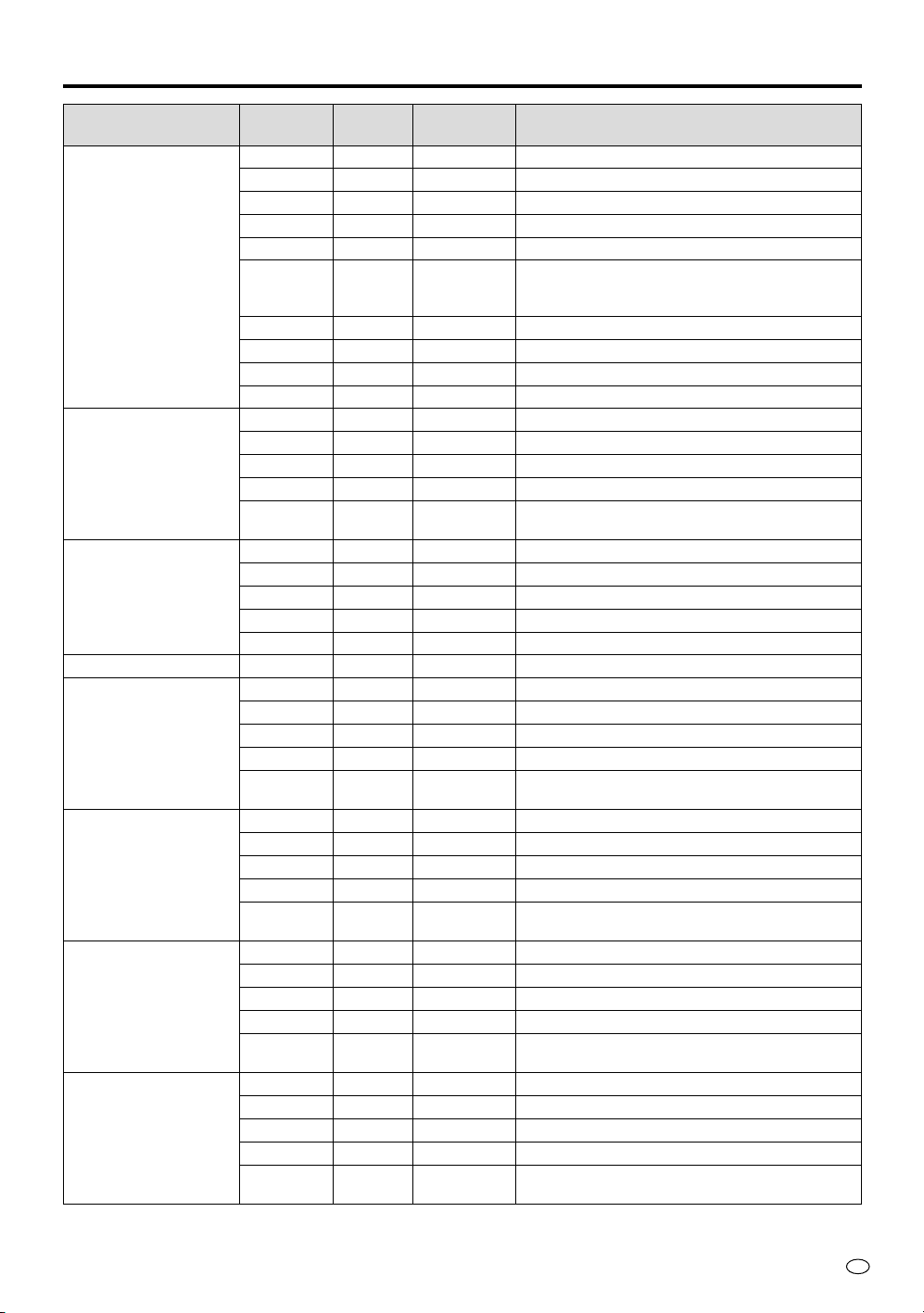
Commands
If an asterisk (*) appears, enter a value in the range indicated under CONTROL CONTENTS.
COMMAND
READ/
WRITE
WRITE
PARAMETER
CONTROL CONTENTSCONTROL ITEM
POWER SETTING
INPUT MODE
INPUT CHECK
DISPLAY
(CH CALL)
INPUT SELECTION
COLOR SYSTEM
SELECTION
AV mode (NORMAL)
PICTURE settings
AV mode (MOVIE)
PICTURE settings
POWR
IMOD
ICHK
/SYSE
CHCL
IRGB
IVED
ICED
MESY
VAPI
VABR
VACO
VATI
VASH
VARE
VABK
VAVE
VAPK
VACT
VBPI
VBBR
VBCO
VBTI
VBSH
VBRE
VBBK
VBVE
VBPK
VBCT
RW
R
W
RW
RW
RW
RW
RW
RW
RW
RW
RW
RW
W
RW
RW
RW
RW
RW
RW
RW
RW
RW
W
RW
RW
RW
RW
*
0
*
1
*
*
*
***
***
***
***
***
*
*
*
*
**
***
***
***
***
***
*
*
*
*
**
0: Sets the unit to the standby status
Responds to current input source (Read only)
1: RGB (PC) input
2: video input
3: component input
Inputs confirmation
Displays the input source as a CH call
0: Display (CH call) off
1: Display (CH call) on
Inputs RGB (PC)
Inputs VIDEO (*)
(* = 1-3)
1: Input COMPONENT1
2: Input COMPONENT2
1: AUTO
2: PAL
3: SECAM
4: NTSC 443
5: NTSC 358
6: PAL-M
7: (reserve)
8: PAL-60
CONTRAST (0-+60)
BRIGHT (–30-+30)
COLOR (–30-+30)
TINT (–30-+30)
SHARP (–30-+30)
0: Displays the setting value on OSD
(except PRO. settings)
1:
Resets the setting value (except PRO. Settings)
BLACK 0: OFF 1: LOW 2:HIGH
VDE 0: OFF 1: ON
F-TONE 0: OFF 1: ON
C-TEMP (–5-+5) (Only for PAL/PAL-60/PAL-M)
CONTRAST (0-+60)
BRIGHT (–30-+30)
COLOR (–30-+30)
TINT (–30-+30)
SHARP (–30-+30)
0: Displays the setting value on OSD
(except PRO. settings)
1:
Resets the setting value (except PRO. Settings)
BLACK 0: OFF 1: LOW 2:HIGH
VDE 0: OFF 1: ON
F-TONE 0: OFF 1: ON
C-TEMP (–5-+5) (Only for PAL/PAL-60/PAL-M)
Note: The unit cannot be controlled from a computer, when it is in Standby mode.
33
US
COMMAND
READ/
WRITE
WRITE
PARAMETER
CONTROL CONTENTSCONTROL ITEM
Connecting to a Computer
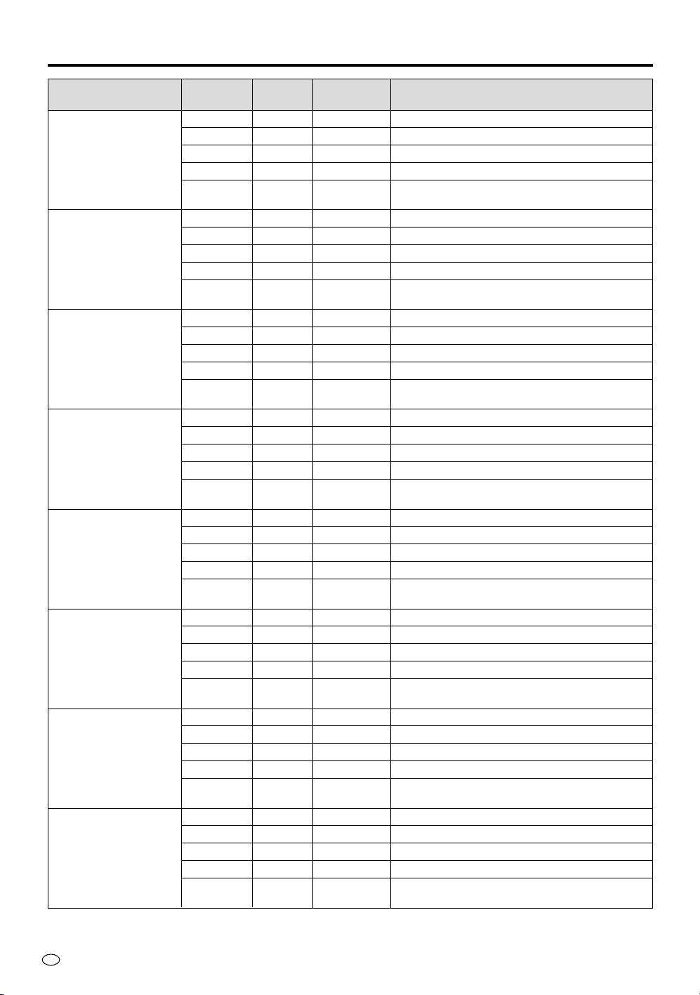
AV mode (GAME)
PICTURE settings
RGB (PC) mode
PICTURE settings
VOLUME
MUTE
SOUND settings
(in the current picture mode)
AV mode (NORMAL)
SOUND settings
AV mode (MOVIE)
SOUND settings
AV mode (GAME)
SOUND settings
VCPI
VCBR
VCCO
VCTI
VCSH
VCRE
VCBK
VCVE
VCPK
VCCT
RAPI
RABR
RARD
RABE
RARE
VOLA
VSPV
RSPV
VLNV
RLNV
MUTE
AABL
AABA
AATE
AALD
AARE
VABL
VABA
VATE
VALD
VAAR
VBBL
VBBA
VBTE
VBLD
VBAR
VCBL
VCBA
VCTE
VCLD
VCAR
RW
RW
RW
RW
RW
W
RW
RW
RW
RW
RW
RW
RW
RW
W
RW
RW
RW
RW
RW
RW
RW
RW
RW
RW
W
RW
RW
RW
RW
W
RW
RW
RW
RW
W
RW
RW
RW
RW
W
***
***
***
***
***
*
*
*
*
**
***
***
***
***
*
**
**
**
**
**
*
***
***
***
*
*
***
***
***
*
*
***
***
***
*
*
***
***
***
*
*
CONTRAST (0-+60)
BRIGHT (–30-+30)
COLOR (–30-+30)
TINT (–30-+30)
SHARP (–30-+30)
0: Displays the setting value on OSD
(except PRO. settings)
1:
Resets the setting value (except PRO. Settings)
BLACK 0: OFF 1: LOW 2:HIGH
VDE 0: OFF 1: ON
F-TONE 0: OFF 1: ON
C-TEMP (–5-+5) (Only for PAL/PAL-60/PAL-M)
CONTRAST (0-+60)
BRIGHT (–30-+30)
RED(–30-+30)
BLUE(–30-+30)
0: Displays the setting value on OSD
1: Resets the setting value
Controls the current volume
Controls the volume of AV speakers /headphones
Controls AV line volume
Controls the volume of PC speakers/headphones
Controls PC line volume
0: MUTE OFF 1: MUTE ON
BALANCE (–30-+30)
BASS (–30-+30)
TREBLE(–30-+30)
0: LOUDNESS OFF 1: LOUDNESS ON
0: Displays the setting value on OSD
1: Resets the setting value
BALANCE (–30-+30)
BASS (–30-+30)
TREBLE(–30-+30)
0: LOUDNESS OFF 1: LOUDNESS ON
0: Displays the setting value on OSD
1: Resets the setting value
BALANCE (–30-+30)
BASS (–30-+30)
TREBLE(–30-+30)
0: LOUDNESS OFF 1: LOUDNESS ON
0: Displays the setting value on OSD
1: Resets the setting value
BALANCE (–30-+30)
BASS (–30-+30)
TREBLE(–30-+30)
0: LOUDNESS OFF 1: LOUDNESS ON
0: Displays the setting value on OSD
1: Resets the setting value
US
34
Connecting to a Computer
COMMAND
READ/
WRITE
WRITE
PARAMETER
CONTROL CONTENTSCONTROL ITEM
RGB (PC) mode
SOUND settings
POSITION settings
(in the current picture
mode)
AV mode/ PC mode
common
AV mode (SIDE BAR)
POSITION settings
AV mode (CINEMA)
POSITION settings
AV mode (WIDE)
POSITION settings
PC mode (SIDE BAR)
POSITION settings
PC mode (CINEMA)
POSITION settings
PC mode (FULL)
POSITION settings
VRBL
VRBA
VRTE
VRLD
VRAR
INCL
INPH
IAHP
IAVP
IARE
(VACL)
(VAPH)
VAHP
VAVP
VAFR
(VBCL)
(VBPH)
VBHP
VBVP
VBFR
(VCCL)
(VCPH)
VCHP
VCVP
VCFR
RACL
RAPH
RAHP
RAVP
RAFR
RBCL
RBPH
RBHP
RBVP
RBFR
RCCL
RCPH
RCHP
RCVP
RCFR
RW
RW
RW
RW
W
RW
RW
RW
RW
W
RW
RW
RW
RW
W
RW
RW
RW
RW
W
RW
RW
RW
RW
W
RW
RW
RW
RW
W
RW
RW
RW
RW
W
RW
RW
RW
RW
W
***
***
***
*
*
***
***
***
***
*
***
***
***
***
*
***
***
***
***
*
***
***
***
***
*
***
***
***
***
*
***
***
***
***
*
***
***
***
***
*
BALANCE (–30-+30)
BASS (–30-+30)
TREBLE (–30~+30)
0: LOUDNESS OFF 1: LOUDNESS ON
0: Displays the setting value on OSD
1: Resets the setting value
*In the AV mode, the CLOCK cannot be adjusted.
*In the AV mode, the PHASE cannot be adjusted.
H-POSI.
V-POSI.
0: Displays the setting value on OSD
1: Resets the setting value
(CLOCK) (reserve)
(PHASE) (reserve)
H-POSI.
V-POSI.
0: Displays the setting value on OSD
1: Resets the setting value
(CLOCK) (reserve)
(PHASE) (reserve)
H-POSI.
V-POSI.
0: Displays the setting value on OSD
1: Resets the setting value
(CLOCK) (reserve)
(PHASE) (reserve)
H-POSI.
V-POSI.
0: Displays the setting value on OSD
1: Resets the setting value
CLOCK
PHASE
H-POSI.
V-POSI.
0: Displays the setting value on OSD
1: Resets the setting value
CLOCK
PHASE
H-POSI.
V-POSI.
0: Displays the setting value on OSD
1: Resets the setting value
CLOCK
PHASE
H-POSI.
V-POSI.
0: Displays the setting value on OSD
1: Resets the setting value

35
US
Connecting to a Computer
COMMAND
READ/
WRITE
WRITE
PARAMETER
CONTROL CONTENTSCONTROL ITEM
IVED___1
OK
MUT E _ _ _ 1
OK
Communication Example: Switching to the AV mode, and muting the sound
Computer The display
Switching to
the AV mode
Setting MUTE
PC mode (DOT BY
DOT)
PC Picture size
AV Picture size
WIDE VIEW setting
(Fit to screen)
INPUT DISPLAY
MIRROR image
AUTO SYNC setting
BRIGHTNESS setting
PICTURE mode
SOUND mode
AV-3 setting
AUTO setting
RDCL
RDPH
RDHP
RDVP
RDFR
RASR
RASV
RFSV
/IMFS
IMDI
IMRE
ADJS
IMAS
VLMP
RLMP
IMPI
IMAU
IMV3
IMAW
RW
RW
RW
RW
W
RW
RW
RW
RW
RW
RW
RW
RW
RW
RW
RW
RW
RW
***
***
***
***
*
*
*
*
*
*
*
*
*
*
*
*
*
*
CLOCK
PHASE
H-POSI.
V-POSI.
0: Displays the setting value on OSD
1: Resets the setting value
1: SIDE BAR
2: FULL
3: DOT BY DOT
4: (DOT BY DOT-WIDE) (reserve)
5: CINEMA
1: SIDE BAR
2: WIDE (/STRETCH)
3: (reserve)
4: (reserve)
5: CINEMA
1: (reserve)
2: STRETCH
3: FULL
Presence/absence of CH call when selecting
input source using command
0: OFF 1: ON
0: OFF 1: ON
0: AUTO SYNC STOP
1: AUTO SYNC START
During AUTO SYNC operation, only the ADJS
command is valid.
0: No AUTO SYNC OSD
1: Displays AUTO SYNC OSD
Brightness (AV) 1: DARK 2: NORMAL 3: BRIGHT
Brightness (PC) 1: DARK 2: NORMAL 3: BRIGHT
1: NORMAL 2: MOVIE 3: GAME
1: NORMAL 2: MOVIE 3: GAME
1: INPUT 2: OUTPUT (FIXED) 3: OUTPUT (VARIABLE)
0: OFF 1: ON
US
36
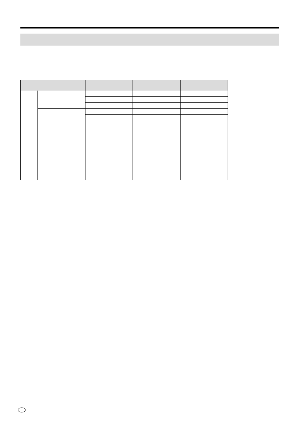
Computer Compatibility Chart
Horizontal Frequency: 15-68.7 kHz
Vertical Frequency: 60-85 Hz
Pixel Clock: 12-80 MHz
Recommended display signals and personal computer signals are as follows;
Connecting to a Computer
Horizontal
Frequency (kHz)
Vertical
Frequency (Hz)
VESA StandardResolution
720 × 400
VGA
640 × 480
SVGA 800 × 600
XGA 1,024 × 768
27.0
31.5
37.9
31.5
34.7
37.9
37.5
43.5
37.9
44.5
48.1
46.9
53.7
56.5
58.1
60
70
85
60
70
72
75
85
60
70
72
75
85
70
72
×
×
×
×
×
×
×
×
×
×
×
37
US
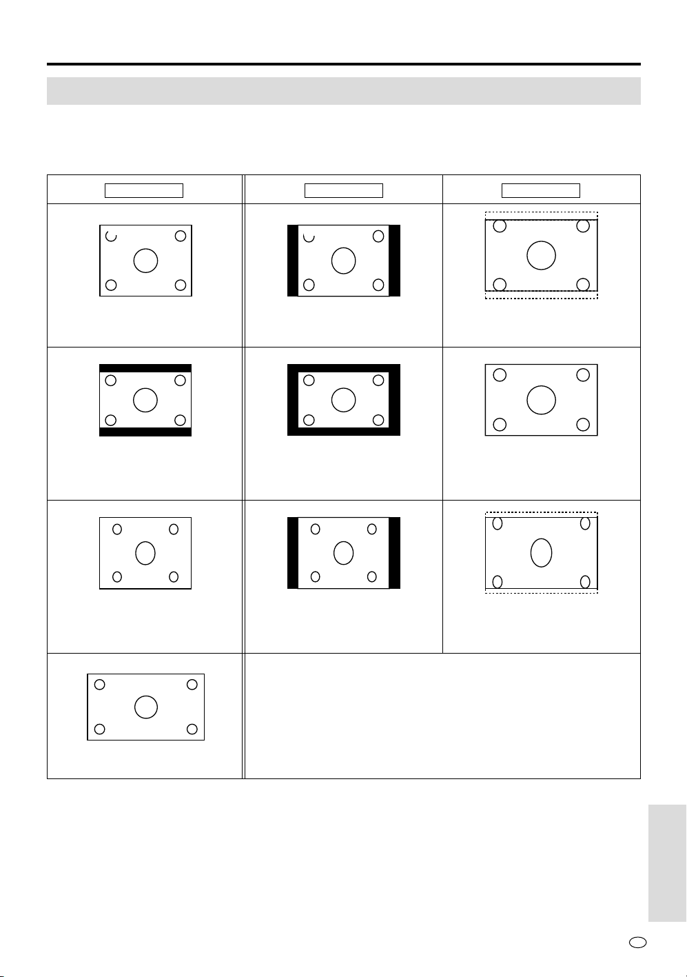
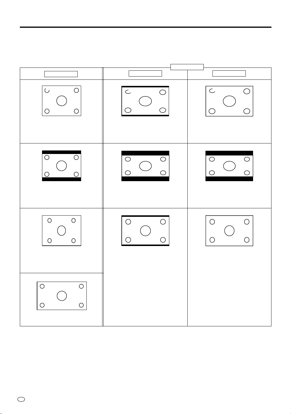
Picture Sizes
In the VIEW mode
The AUTO setting of the SIDE BAR mode and the WIDE mode is a function that allows you to enjoy
automatic switching to the CINEMA picture when NTSC letter box signal is received.
Reference
9:00
Subtitles
Regular video (broadcast)
signal
Letter Box
Wide screen with black bands
at the top and bottom of the
display
Squeeze (left-right compression)
Picture when playing back
DVD's with squeeze recording
For high-grade pictures such as
HDTV (Wide size)
Subtitles
9:00
Side Bars appear on the left
and right.
Screen with black bands at the
top and bottom and left and
right of the display.
Screen with black bands at the
left and right of the display.
Picture appears stretched
vertically.
Subtitles
9:00
Picture is perfectly round with
projections enlarged at the top
and bottom.
Full picture is included. The
picture is perfectly round.
Picture is projected at the top
and bottom. The picture is
stretched vertically.
SIDE BAR
Input signal
CINEMA
Automatically switches to the wide mode.
Reference
US
38
Reference
In the OPTION mode
Depending on the WIDE VIEW setting, the display of the wide mode changes. The display also changes
depending on the input video signal.
9:00
Subtitles
Regular video (broadcast)
signal
Letter Box
Wide screen with black bands
at the top and bottom of the
display
Squeeze (left-right compression)
Picture when playing back
DVD's with squeeze recording
For high-grade pictures such as
HDTV (Wide size)
Picture is stretched horizontally
while black bands appear to
make the vertical-horizontal
ratio 16:9.
Full picture is visible but black
bands appear at the top and
bottom. (Maximum stretching in
the horizontal direction)
Full picture is visible. Picture
becomes perfectly round. Black
bands appear at the top and
bottom.
9:00
Subtitles
Picture is stretched over the
entire screen.
Picture is stretched over the
entire screen.
Full picture is visible. Picture is
slightly stretched vertically.
STRETCH
Input signal
FULL
WIDE VIEW
Subtitles
9:00
US
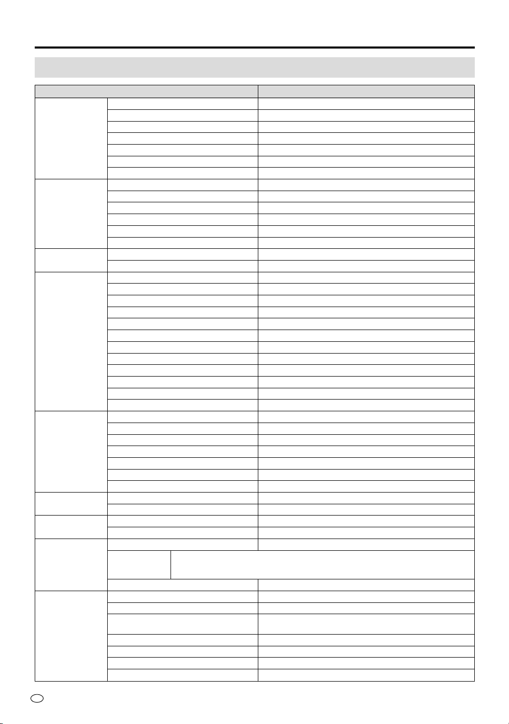
40
Specifications
ITEM LC-28HM2
LCD Size (Diagonal) 28" WIDE XGA LCD
Number of pixel 2,949,120 (1280 dots × 3 RGB × 768 lines)
Low reflection Low reflection coating
Brightness 400 cd/m
2
(at normally white)
Viewable angle Left to right 160°
Up to down 150°
Life of backlight 60,000 hours (at normal mode)
VIDEO Multi system capability PAL/PAL-M/PAL-60/NTSC(N358/N443)/SECAM
Digital comb filter for PAL/SECAM Yes
3D Y/C separator for NTSC Yes
Wide-band chroma IC Yes
Gamma correction circuit Yes
Line scanning for PAL/SECAM Yes
AUDIO Separate speaker system –
Recommendable optional speaker Bose System side speakers; 25 W (12.5 W+12.5 W)
INTERFACES Display: Display input 26 pins System link
(TERMINALS) Speaker terminals For Bose System side speaker
Power Inlet for AC power cord
AVC system: Display output 26 pins System link
AV input1 S-video, Video, Audio; R/L
AV input2 S-video, Video, Audio; R/L
AV input3/AV OUTPUT Video, Audio; R/L
COMPONENT1 Audio; R/L, Video; Y, PB(CB), PR(CR)
COMPONENT2 Audio; R/L, Video; Y, PB(CB), PR(CR)
PC RGB input, Audio input, RS-232C control
Headphones jack
9
/
64
" [3.5 mm] diameter mini-jack, 16 ohms
Power Inlet for AC power cord
FUNCTIONS OSD Language English
Reverse/Invert Mirror image only
Brightness NORMAL/BRIGHT/DARK
Component capability 480i/480p/1080i/720p
PC capability VGA/SVGA/XGA
WIDE view mode STRETCH/FULL
AUTO wide view (NTSC picture only) Automatically changing to CINEMA mode.
POWER SUPPLY AC auto power voltage capability AC 110 V-240 V, 50/60 Hz
Power consumption AVC system; AC 32 W Display; AC 140 W
RATED Left terminal out put for speakers DC 13.65 V max.
INDICATORS RS-232C input terminal DC 15 V max.
APPEARANCE Exterior color Silver
Outside AVC system; 14-
11
/64" [360 mm] × 2-
9
/16" [65 mm] × 14-
3
/8" [365 mm]
dimensions Display with stand; 27-
13
/64" [690.8 mm] × 20-
7
/16" [519 mm] × 10-
29
/32" [277 mm]
(W) × (H) × (D) Display without stand; 27-
13
/64" [690.8 mm] × 17-
41
/64" [448 mm] × 2-
11
/32" [59.7 mm]
Net weight Display; 29.3 lbs [13.3 kg] AVC system; 7.7 lbs [3.5 kg]
ACCESSORIES Remote control Infrared wireless type
Batteries for R/C Size AA×2
AC power cord Type A ×2 (12ft.5-
39
/
64
" [3.8 m] for Display, 5ft.10-
55
/
64
"
[1.8 m] for AVC system)
System cable 26 pins plug (male to male)
Cable clamp 4 pcs
AVC system terminal cover 1 pc
Operation manual language: English/French/Spanish/Portuguese
Reference

41
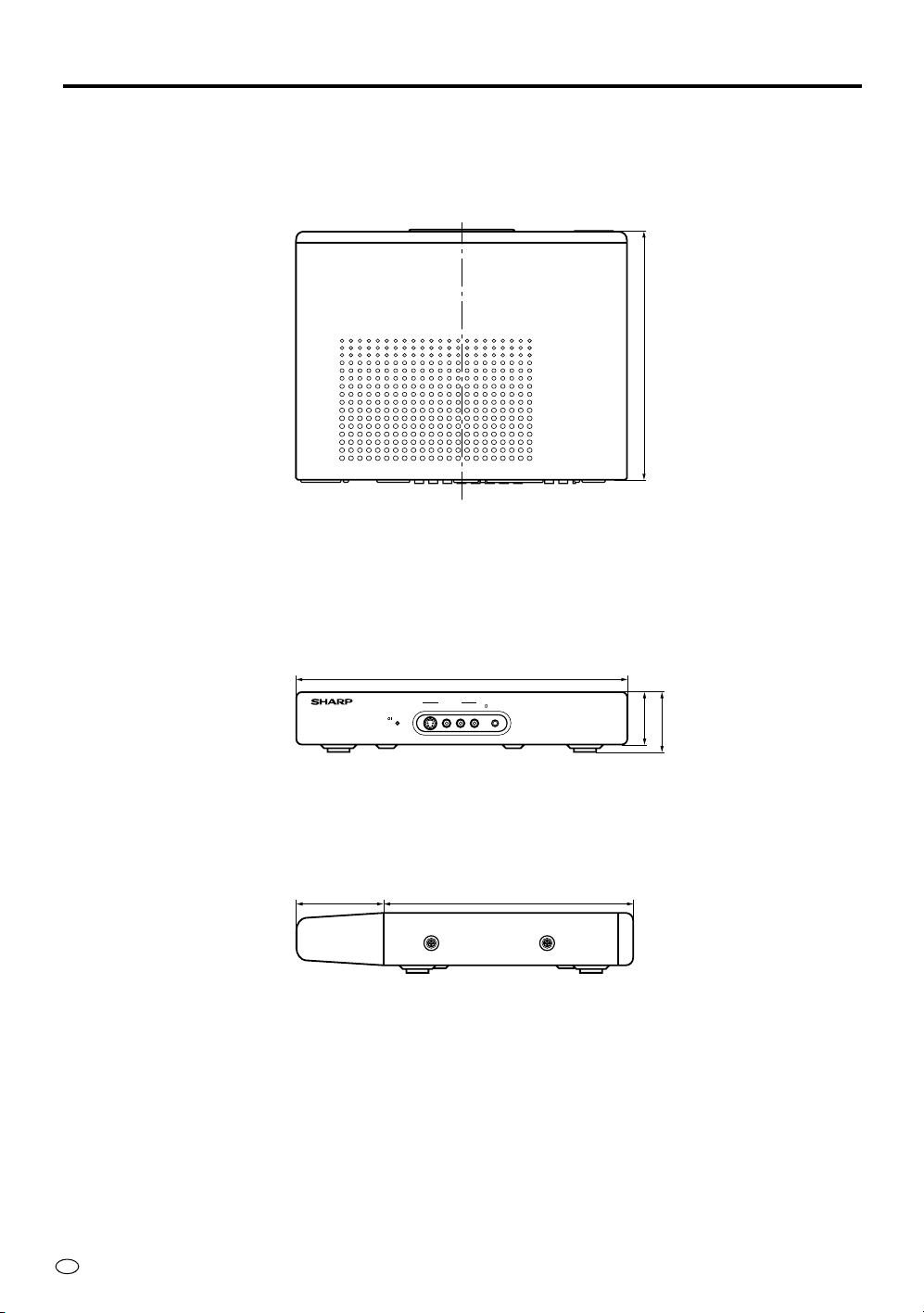
US
Dimensional Drawings
Display
Reference
POWER
17-
41
/64" [448 mm]
27-
13
/64" [690.8 mm]
20-
7
/16" [519 mm]
19-
3
/32" [485 mm]
10-
29
/32" [277 mm]
2-
11
/32"
[59.7 mm]
10-
29
/32" [277 mm]
7
/8"
[22.2 mm]
4-
7
/16"
[112.8 mm]
US
42
Reference
AVC System
AVC SYSTEM
POWER
14-
11
/64" [360 mm]
2-
1
/4" [57 mm]
2-
9
/16" [65 mm]
S-VIDEO VIDEO L-AUDIO-R
HEAD
PHONE
AV INPUT 2
3-
47
/64" [95 mm]
10-
5
/8" [270 mm]
10-
5
/8" [270 mm]
SHARP ELECTRONICS CORPORATION
Sharp Plaza, Mahwah, New Jersey 07430-2135
LIMITED WARRANTY
END-USER LIMITED WARRANTY
SHARP ELECTRONICS CORPORATION warrants to the first end user purchaser that this Sharp brand product (the
“Product”), when shipped in its original container, will be free from defective workmanship and materials, and agrees that it
will, at its option, either repair the defect or replace the defective Product or part thereof with a new or remanufactured
equivalent at no charge to the purchaser for parts or labor for the period(s) set forth below.
This warranty does not apply to any appearance items of the Product nor to the additional excluded item(s) set forth below
nor to any Product the exterior of which has been damaged or defaced, which has been subjected to improper voltage or
other misuse, abnormal service or handling, or which has been altered or modified in design or construction.
In order to enforce the rights under this limited warranty, the purchaser should follow the steps set forth below and provide
proof of purchase to the servicer.
To the extent permitted by applicable state law, the warranties set forth herein are in lieu of, and exclusive of, all other
warranties, express or implied. Specifically, ALL OTHER WARRANTIES OTHER THAN THOSE SET FORTH ABOVE ARE
EXCLUDED. ALL EXPRESS AND IMPLIED WARRANTIES INCLUDING THE WARRANTIES OF MERCHANTABILITY,
FITNESS FOR USE, AND FITNESS FOR A PARTICULAR PURPOSE ARE SPECIFICALLY EXCLUDED. If, under
applicable state law, implied warranties may not validly be disclaimed or excluded, the duration of such implied warranties
is limited to the period(s) from the date of purchase set forth below.
Neither the sales personnel of the seller nor any other person is authorized to make any warranties other than those
described herein, or to extend the duration of any warranties beyond the time period described herein on behalf of Sharp.
The warranties described herein shall be the sole and exclusive warranties granted by Sharp and shall be the sole and
exclusive remedy available to the purchaser. Correction of defects, in the manner and for the period of time described
herein, shall constitute complete fulfillment of all liabilities and responsibilities of Sharp to the purchaser with respect to the
Product, and shall constitute full satisfaction of all claims, whether based on contract, negligence, strict liability or otherwise.
In no event shall Sharp be liable, or in any way responsible, for any damages or defects in the Product which were caused
by repairs or attempted repairs performed by anyone other than an authorized servicer. Nor shall Sharp be liable or in any
way responsible for any incidental or consequential economic or property damage. Some states do not allow limits on
warranties or on remedies for breach in certain transactions; in such states, the limits herein may not apply.
Model Specific Section
Your Product Model Number & Description: LC-28HM2 LCD AV Monitor
(Be sure to have this information available when you need service for
your Product.)
Warranty Period for this Product: One (1) year parts and labor from the date of purchase.
Additional Item(s) Excluded from
Warranty Coverage (if any): None
Where to Obtain Service: From a Sharp Authorized Servicer located in the United States.
To find the location of the nearest Sharp Authorized Servicer, call
Sharp toll free at 1-800-BE-SHARP.
What to do to Obtain Service: Ship prepaid or carry in your Product to a Sharp Authorized Servicer.
Be sure to have Proof of Purchase available. If you ship the Product,
be sure it is insured and packaged securely.
TO OBTAIN PRODUCT INFORMATION, CALL 1-888-GO-SHARP.
Calling for Service
For location of the nearest Sharp Authorized Service, or to obtain product literature, accessories, supplies, or customer
assistance, please call 1-800-BE-SHARP.