Owner 's Manual for Water heater
OPERATING INSTRUCTIONS
About the control panel
Displaying Temperature Setpoint
The GeoSpring™ control will display the temperature setpoint anytime a button on the control is pressed. After 30 seconds of inactivity, the display will go blank. However, the LED indicating the selected mode of operation will remain lit. To wake the control at any time to see the temperature setpoint, press any button on the control.
Turning on the Water Heater
There is no power button for this unit. Once the water heater is wired and power is supplied, it will be on. The display will show the current water temperature setting and an LED will illuminate indicating the current operating mode.
To comply with safety regulations, the controls are factory preset to 120°F (49°C) and Hybrid Mode. It is recommended that the unit be set to Heat Pump mode to maximize energy savings. Operating in Hybrid mode provides a balance of energy savings and hot water use convenience. Reported energy consumption is based on operating the unit in Hybrid mode at required Department of Energy (DOE) test conditions. Operating at lower temperature settings or in Heat Pump mode will provide even greater energy savings.
To Adjust the Temperature
Follow these steps:
1. Press the UP or DOWN arrow on the control panel key pad to desired temperature.
2. Press ENTER to accept the new setting.
Note: To change between °F and °C, press and hold MODE.
Control Features

1. Display
2. Operating Modes
3. Vacation Mode
4. Mode Selector
Use this button to alternate between available modes.
5. Arrow Pads
Use these buttons to adjust the temperature setting.
6. Enter Key
Use this button to confirm temperature setting following adjustment.
7. Filter Reset
The filter is dirty and requires cleaning when the Red light is illuminated. Filter is located on top of the water heater. Press button and hold for 5 seconds to reset filter alarm.
8. Power Saver Override
If operating with a demand response program through a local utility company, press and hold to bring unit out of Power Saver mode.
9. Appliance Communication Module Port
For use with optional ConnectPlus communication module (see page 8 for details).
10. Anode Reset (on some models)
When the red light is illuminated, the system has indicated that the anode rod is approaching end of life and it is recommended to replace it. Press button once to silence alarm. Press and hold for 10 seconds to reset the anode alarm after replacing. Call GE Appliances Service to replace the anode rod. Failure to replace the anode rod will void warranty coverage and may result in a tank leak. (See page 12 for instructions to change the anode rod.) GE Appliances Service: 888.4GE.HEWH (888.443.4394).
Operational Modes
This water heater defaults to the Hybrid operating mode.
To select available modes listed below:
�1. Press the MODE button until the LED next to the desired Operating Mode is illuminated.
In Hybrid Mode and High Demand/Boost Mode, the Electric/Standard Mode LED will flash anytime the heating elements are active, such as during the initial recovery from a large draw. This is normal and does not indicate an operating issue.
Cold Climate Efficiency
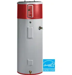
This heat pump water heater is compliant with the Tier 3 Advanced Water Heater Specification, v6.0 (formerly known as the Northern Climate Specification) and may qualify for rebates in some regions. Compliance with the specification does not require a Cold Climate Efficiency (CCE) setting for models produced after 2015, and as a result the CCE setting may not be available on your model. Check with your local utility for available rebates and requirements.
A ducting kit is available for use with your heat pump water heater if desired. [See for ducting kit details].
Ducting kits may be installed to achieve directed flow of inlet and outlet air for heat pump operation, or to allow water heater installation in rooms less than 700cu. ft.(19.8 cu.m.) or without louvered doors, as specified in the installation instructions.
Heat Pump Mode—RECOMMENDED FOR MAXIMUM SAVINGS
Heat Pump is the most energy-efficient mode for this water heater. It takes heat from the surrounding air to heat the water. The time it takes to heat the water is longer in this mode, so it may not be sufficient if you have a high-demand situation such as a large household or company.
Hybrid Mode
Hybrid mode combines the energy efficiency of Heat Pump with the recovery speed and power of the Electric/ Standard mode in most water usage situations. Hybrid mode will allow the unit to perform like a standard electric water heater while providing significant energy savings.
NOTE: Energy Guide unit performance, energy consumption and savings are based on non-ducted installations in Hybrid mode at required Department of Energy (DOE) test conditions. Operating in Heat Pump mode may provide a greater savings in energy and operating costs than the claimed savings.
High Demand/Boost Mode
This mode may be necessary if your household has a higher-than-average water usage or the unit is undersized for the household water demands. In this mode, the unit will use the electric heating elements only when the water demand rate is high. When using the heating elements, the water temperature will recover at a faster rate but it will use more energy to heat it. Unlike Electric/Standard mode, it will use the heating elements only when needed, and use the heat pump when water demand rates are lower.
NOTE: The difference between Hybrid mode and High Demand/Boost mode is that in High Demand/Boost mode the heating resistive elements are activated sooner than in Hybrid mode.
Electric/Standard Mode
This mode uses only the upper and lower heating resistance elements to heat the water, stopping the cool air discharge during heat pump operation. The time it takes to heat the water is less in this mode, but it is the LEAST energy-efficient mode.
Follow these steps to set Electric/Standard mode:
1. Select Electric/Standard mode using the MODE button.
2. Input the total days to remain in Electric/Standard mode using the UP arrow. The default is 3 days, maximum 99 days.
3. Press ENTER
At the end of the selected time period, the unit will switch
back to the previously selected more energy-efficient mode.
NOTE: In this mode the green LED light will flash after 48 hours as an indication that the unit is not operating in the most energy efficient mode. The unit will continue to operate in this mode and does not indicate an operating issue.
Vacation Mode
This feature is recommended when you will be away from the home for an extended period of time and hot water is not needed. In this mode, the unit will reduce the water temperature setting to 50°F (10°C) and will use the most efficient heating mode to conserve energy while the heater is sitting idle. The unit will automatically resume heating one day before your return, so that hot water will be available.
To set Vacation Mode:
1. Select Vacation by pressing the MODE button.
2. Input the total number of days you will be gone by pressing the UP arrow. The default is 7 days, maximum 199, or remain in Vacation Mode indefinitely by selecting “—”.
3. Press ENTER.
For example, if you will be gone 14 days, set Vacation mode for 14 days using the steps above. The temperature setting will automatically reduce to 500F (100C) for 13 days. At the end of the 13th day, the previous operating mode and temperature setting will reset to ensure hot water is available upon your return.
Extended Shutdown Periods
If the water heater is to remain idle for an extended period of time, the power and water to the appliance should be turned off and the water heater drained to conserve energy and prevent a buildup of dangerous hydrogen gas. This unit has no power button, power can only be shut off at the circuit breaker or disconnect switch.
If the water heater has an anode depletion sensing feature (some models) and the water heater cannot be drained, it is recommended to leave the power turned on with the water heater in vacation mode to ensure that the feature will continue to operate properly while still conserving energy.
The water heater and piping should be drained if they might be subjected to freezing temperatures.
After a long shutdown period, the water heater’s operation and controls should be checked by qualified service personnel. Make certain the water heater is completely filled again before placing it in operation.
NOTE: Refer to the Hydrogen Gas Caution in the Operating Instructions (see page 3).
ConnectPlus Module (where installed)
Your GeoSpring water heater is GE Appliances WiFi Connect compatible using the GE Appliances ConnectPlus module, sold separately. The ConnectPlus module will allow your water heater to communicate with your smart phone for remote monitoring, control of settings and vacation mode, and receiving alerts and notifications. Please visit GEAppliances/connect to learn more about connected appliance features, to learn which connected appliance App’s will work with your Smart Phone, and to learn where you can purchase a GE Appliances ConnectPlus module.
Installation
The ConnectPlus is equipped with magnets in the base of the module that enable it to attach to the painted metal exterior of the GeoSpring water heater. To connect your water heater to the internet through your home’s wireless internet router, plug the ConnectPlus cable into the communication port on the front of your GeoSpring and follow the activation instructions on your Smart Phone’s App.
WiFi Connectivity: For assistance with appliance or ConnectPlus network connectivity, please call 1-800220-6899.
The ConnectPlus module has the FCCID located on the back of the module.
RF Exposure - This device is only authorized for use in a mobile application. At least 20 cm of separation distance between the ConnectPlus device and the user’s body must be maintained at all times.

Notice: The Communication Port connection carries voltage not compatible to computers or accessories. Do NOT plug laptops, modems, routers, etc. into the Communication Port. Use only with designated GE Appliances Accessories. Connection to computers and accessories may result in product damage.
CARE AND CLEANING
Exterior Surfaces
Hand wash with warm water only.
Routine Preventive Maintenance
DANGER Risk of Scald - Before manually operating the relief valve, make certain no one will be exposed to the danger of coming in contact with the hot water released by the valve. The water may be hot enough to create a scald hazard. The water should be released into a suitable drain to prevent injury or property damage.
NOTE: If the temperature and pressure-relief valve on the hot water heater discharges periodically, this may be due to thermal expansion in a closed water system. Contact the water supplier or your plumbing contractor on how to correct this. Do not plug the relief valve outlet.
Properly maintained, your water heater will provide years of dependable trouble-free service. It is suggested that the following yearly preventive maintenance program be established.
1. Inspect Temperature & Pressure Relief Valve.
2. Inspect heating elements, TCO, and wiring to each.
3. Drain and Flush the water heater tank.
4. Clean the air filter.
5. Clear the condensate drain pan and drain lines.
6. Anode rod must be removed and inspected.
Temperature and Pressure-Relief Valve:
Once a year, it is recommended to lift and release the lever handle on the temperature and pressure-relief valve, located on the front-right side of the water heater, to make certain the valve operates freely. Allow several gallons to flush through the discharge line to an open drain.
Heating Elements and TCO:
Once a year, it is recommended to inspect the heating elements, TCO, and wiring to each. Inspection should be completed by service personnel qualified in electrical appliance repair.
Most electrical appliances, even when new, make some sound when in operation. If the hissing or singing sound level increases excessively, the electric heating element may require cleaning. Contact a qualified installer or plumber for inspection.
Draining and Flushing the Water Heater
CAUTION Risk of Shock - Shut off power to the water heater before draining water.
DANGER Risk of Scald - Before manually operating the relief valve, make certain no one will be exposed to the hot water released by the valve. The water drained from the tank may be hot enough to present a scald hazard and should be directed to a suitable drain to prevent injury or damage.
A water heater’s tank can act as a settling basin for solids suspended in the water. It is therefore not uncommon for hard water deposits to accumulate in the bottom of the tank. To clean the tank of these deposits, it is recommended to drain and flush the water heater tank once a year. To drain the water heater, follow these steps:
1. Turn off power to the unit. The electric heating elements will become damaged if operated without water.
2. Attach a garden hose to the drain valve located at the bottom of the unit and direct that hose to a drain.
3. Turn off the cold water supply.
4. Admit air to the tank by opening a hot water faucet or lifting the handle on the relief valve.
5. Open the drain valve with a flat screwdriver.

Flushing the Tank:
1. Follow steps above to drain the water heater.
2. Once the water heater is empty, with the drain valve open and garden hose attached to the drain valve, turn on the cold water supply.
3. Allow several gallons to flush through the drain valve and hose to an open drain.
4. Turn off the water supply and allow any water remaining in the tank to drain.
5. Repeat steps 3 and 4 until water runs clear.
6. Close the drain valve and fill the tank before returning power to the unit. The tank is full when water runs out of a nearby open hot water faucet.
Flushing should be done with an empty tank to promote additional removal of sediment.
Note: See page 14 for product schematic.
Cleaning the Filter
In the Hybrid, Heat Pump, and High Demand/Boost modes, the water heater pulls air through the filter and out the back of the unit. The filter is in place to protect the evaporator from dirt and dust.
A clean air filter is important to get the highest efficiency. Occasionally this filter will need to be cleaned. When the filter requires cleaning, the Red light above the FILTER button will illuminate and an alarm will sound.
NOTE: If the filter gets too dirty, the unit will automatically switch to Electric/Standard mode and energy savings will be lost.
Leave the power on. Remove the filter from the top of the unit. Squeeze two tabs and lift to remove the air filter. Once it has been removed, the filter can be vacuumed or wiped clean with a damp cloth or rinsed with warm water.
Once the filter has been cleaned and dried, it can be replaced by aligning it into the slots in the top of the unit and pushing it down into place.
After the clean filter has been reinstalled, press and hold the FILTER button to reset the alarm. The unit will automatically revert to the previously selected operating mode. If a heating cycle is active when the filter alarm is reset, it will continue in Electric/Standard mode to finish the cycle, then automatically revert to the previously selected mode.
IMPORTANT: Filter must be cleaned when the alarm is displayed. A dirty filter will make the system work harder and result in a reduction of efficiency and possible damage to the system. In order to get the best energy efficiency available, make sure your filter is clean.
NOTE: If the dirty filter alarm returns within a few days after cleaning and resetting, it may be an indication of a refrigerant leak. Further diagnosis by a service technician is necessary.

Clearing the Condensation Drain Tube
The main drain is intended to carry all condensate away. If it is clogged, the heat pump will stop operating, the display will show F20, and an alarm will sound. Press any button to silence the alarm, then clear the condensate drain by removing any drain lines and connections, and clearing debris. Reattach drain lines and connections, then allow the water heater to run. The GeoSpring water heater will continue to produce hot water using the backup resistance heating elements until the condensate drain has been cleared, and is able to drain properly. Once the drain has been cleared, the unit will then be able to operate the heat pump again.
Periodically inspect the drain lines and clear any debris that may have collected in the lines.
See Installation Instructions for more information.

Routine Preventative Maintenance Anode Rod
Anode rods are designed and installed to protect and
extend the life of residential water storage tanks.
The anode rod must be removed from the water heater’s tank and inspected annually, and replaced when more than 6” (15.2 cm) of core wire is exposed at either end of the rod.* Note: Artificially softened water will cause the anode rod to consume more rapidly.
Due to shock hazard and to prevent accidental water leaks, this inspection should be done by a qualified servicer or plumber, and requires that the electric power and cold water supply be turned off before servicing the anode rod.
NOTICE: Do not remove the anode rod from the water heater's tank except for inspection and/or replacement, as operation with the anode rod removed will shorten the life of the glass-lined tank and will void warranty coverage.
Some areas have water conditions that may cause an odor to develop in the water heater. Aluminum-Zinc alloy replacement rods are available to address the condition.
*NOTE: Failure to replace the anode rod when consumed risks voiding the warranty for the tank. Warranty coverage for all other components remains intact, and is unaffected by this maintenance requirement. The replacement anode rod, and the inspection for consumption are not covered by warranty.
Additional information for models with an anode depletion sensing feature (Anode button on the control):
When the depletion-sensing anode rod nears end of life, the red light above the ANODE button will illuminate and the control will beep and display F16. When this occurs, the anode rod must be inspected and replaced if the core wire at the top of the anode rod is exposed or if the length of the anode rod is less than 33” (83.8cm).* It is recommended to replace the anode rod as soon as possible to ensure that the tank will continue to be protected from corrosion. Call GE Appliances Service to order or to replace the anode rod. (See page 12 for instructions to change the anode rod.) GE Appliances Service: 888.4GE.HEWH (888.443.4394).
Press the ANODE button once to silence the alarm. Once replaced, reset the alarm by pressing and holding the ANODE button for 10 seconds until the control beeps and the LED above the button turns off.
If an Aluminum-Zinc anode rod is installed to address a water odor condition, the anode depletion sensing feature must be disabled. If disabled, annual inspections of the anode rod are required since the water heater will no longer be capable of alerting for a depleted anode rod.
To disable the feature:
1. Upon power-up following an Aluminum-Zinc anode rod installation, the control will sound an alarm and F17 will display. Press the ANODE button to quiet the alarm.
2. Press the ANODE button 3 times. “Off” or “On” will display confirming that the feature has been disabled/ enabled.
To enable the feature if a new anode depletion sensing anode rod is installed, follow Step 2 above.
Note: If the display is blank, press any button to wake the control before entering a button combination.
NOTE: If the water heater has been installed with a device that periodically cuts power to the water heater, the accuracy of the anode rod depletion sensing feature may become compromised and anode rod inspection every 2-3 years is required.
If the water heater will be inactive for a long period of time and the water heater cannot be drained, it is recommended to leave the power turned on with the water heater in vacation mode to ensure that the feature will continue to operate properly while still conserving energy.
NOTE: Refer to the Hydrogen Gas Caution in the Operating Instructions (see page 3).
Anode Rod Maintenance and Service
CAUTION - IMPORTANT SAFETY NOTICE
This information is intended to use by individuals possessing adequate background of electrical, electronic and mechanical experience. Any attempt to repair a major appliance may result in personal injury and property damage. The manufacturer or seller cannot be responsible for the interpretation of this information, nor can it assume any liability in connection with its use.
Tools needed:
• T20 Torx Screwdriver
• Slot Screwdriver
• Tape
• Socket Wrench
• Socket Extention 12” long
• 1 1/16” Socket
• Softset Sealant
• Anode Rod, if needed
* See page 24 for part ordering instructions
To service the Anode Rod:
1. Disconnect power, shut off the water supply, and partially drain one or two gallons from the water heater through the lower drain valve.
2. Remove the filter, trim ring, and front top cover as shown in Illustration A.

3. Reinstall the trim ring, place a protective layer of tape on sheet metal edges, as shown in Illustration B.

4. If present, remove insulation to uncover the anode rod as shown in Illustration C. Unplug anode wire (on some models).

5. Using a 1 V16” socket and extension, unscrew the anode rod, then lift out to inspect as shown in Illustration D.

6. To install the anode rod, seal the threads with soft set sealant, thread into the port and using the torque wrench tighten to 50 ± 5 ft-lbs of torque. Plug in the wire for the anode rod (some models). If an Aluminum-Zinc or other non-sensing anode rod is installed, the anode depletion sensing feature must be disabled and the wire end taped (some models).
7. Turn water supply on, open a tap to remove any air in plumbing system, inspect for leaks, then reassemble the unit in reverse order as shown in Illustration A, and turn the power on. Reset the ANODE button (some models) by pressing and holding for 10 seconds to indicate that a new anode depletion sensing anode rod is installed.
Installation Instructions
The location chosen for the water heater must take into consideration the following:
LOCAL INSTALLATION REGULATIONS
This water heater must be installed in accordance with these instructions, local codes, utility codes, utility company requirements or, in the absence of local codes, the latest edition of the National Electrical Code. It is available from some local libraries or can be purchased from the National Fire Prevention Association, Batterymarch park, Quincy, MA 02169 as booklet ANSI/NFPA 70.
POWER REQUIREMENTS
Check the markings on the rating plate of the water heater to be certain the power supply corresponds to the water heater requirements.
NOTE: 208V installations may experience lower performance.
LOCATION
The water heater and water lines should be protected from freezing temperatures and high-corrosive atmospheres. Do not install the water heater in outdoor, unprotected areas.
Locate the water heater in a clean dry area as near as practical to the area of greatest heated water demand. Long uninsulated hot water lines can waste energy and water. Unit must be installed in a level location.
NOTE: This unit is designed for any common indoor installation in a space with at least 700cu.ft. (19.8cu.m) (example 10’ x 10’ x 7’) including: garage, utility room, attic, closet, etc. It can be installed in rooms smaller than 700 cu.ft. (19.8cu.m) with the installation of a louvered door, or two louvered sections (one at the top and one at the bottom of the door or wall for airflow), or a GE Appliances ducting kit (see geospring for details). Louvers should have 240 square inches (0.15 m2) of open airflow area or greater.
Servicing the water heater requires proper installation such that the air filter, covers, trim ring, and front panels can be removed to permit inspection and servicing. Reference installation instructions found in this manual.
Attic installations require access stairs and solid flooring with no exposed floor joists up to the installation location. Moving the water heater or other appliances to provide service to the water heater is not covered under warranty.
NOTE: The heat pump operating range is 35°F to 120°F (2°C to 49°C). If the ambient temperature is outside of this range, the heat pump will turn off and the electric elements will be used until the ambient temperature returns to within the operating range.
CAUTION The water heater should not be located in an area where leakage of the tank or connections will result in damage to the area adjacent to it or to lower floors of the structure. Where such areas cannot be avoided, it is recommended that a suitable catch pan, adequately drained, be installed under the water heater.
Required clearances:
There must be a 7” (17.8 cm) clearance between any object and the rear and sides of the water heater in the event service is needed. A minimum 8“ (20.3cm) clearance above the water heater to remove the filter for cleaning and for service access, and clear access to the front of the water heater, is recommended. Installations that require 6” clearance on the sides or rear of the water heater for earthquake straps are also acceptable. In these cases, additional clearance must be provided on the opposite side of the unit to allow for service access. The hot and cold water plumbing and electrical connections must not interfere with the removal of the filter.
If a separate GE Appliances ducting kit is purchased, additional space is required above and to the rear of the water heater for installation. Consult the ducting kit manual for specific instructions. See for details.

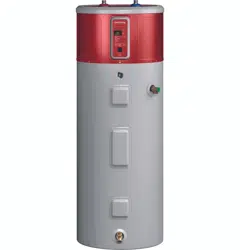
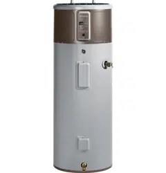
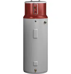
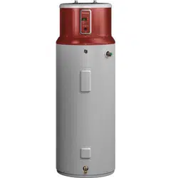
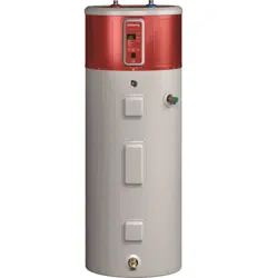
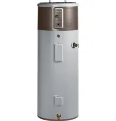
Model appearance may vary
Catch Pan Installation (If required)

NOTE: Auxiliary catch pan MUST conform to local codes. Catch Pan Kits are available from the store where the water heater was purchased, a builder store or any water heater distributor. The catch pan should be 2” (5.1 cm) minimum larger than the Water Heater base diameter. To prevent corrosion and improve Drain Valve access it is recommended that the water heater be placed on spacers inside the catch pan.
CONDENSATION DRAIN CONNECTION
This unit has a condensate drain; therefore a floor or other drain no higher than 36” (91.4cm) above the floor must be available in close proximity to the water heater to allow for the shortest possible drain line with minimal turns to be installed. Drain must meet state and local codes. It is important to install a 3At” FNPT fitting suitable for either rigid or flexible drain line to the primary drain port coming off the side of the unit. Diameter reductions from a 3At” drain line are discouraged.
Ensure that the rigid or flexible drain line maintains a downward slope to allow for proper gravity drainage of condensate to the drain and to allow for proper function of the condensate drain blockage sensor (see page 10). If no drain is available, then a common condensate pump with a capacity no less than 1 gallon (3.8L)/day must be purchased and installed. It is important to route the flexible or rigid drain line so that the discharge water cannot contact live electrical parts or cause water damage .

Additional parts needed:
1- Flexible or rigid %” drain line and associated %-FNPT fitting
THERMAL EXPANSION
If a check valve is present on the inlet water line, it will create a “closed system.” Heating water in a closed system creates an increase in pressure within the water system because the pressure is not able to dissipate in the main supply line. Referred to as “thermal expansion”, the rapid pressure increase can cause the relief valve to operate (releasing water) during each heating cycle, potentially causing premature failure to the valve or even the water heater. The suggested method of controlling thermal expansion is to install an expansion tank in the cold water line between the water heater and the check valve as shown in the following illustrations. Contact your installing contractor, water supplier, or plumbing inspector for additional information.
WATER SUPPLY CONNECTIONS
Refer to the illustration below for suggested typical installation. The HOT and COLD water connections are clearly marked and are %” NPT on all models. When connecting to the inlet/outlet ports, the use of %”female NPT tapered thread fittings with use of thread sealant is recommended. The installation of unions is recommended on the hot and cold water connections so that the water heater may be easily disconnected for servicing if necessary.
NOTE: Install a shut-off valve in the cold water line near the water heater. This will enable easier service or maintenance of the unit later.
IMPORTANT: Do not apply heat to the HOT or COLD water connections. If sweat connections are used, sweat tubing to adapter before fitting the adapter to the cold water connections on heater. Any heat applied to the hot or cold water connection will permanently damage the internal plastic lining in these ports.
TYPICAL INSTALLATION

RELIEF VALVE
WARNING Risk of Unit Damage - The pressure rating of the relief valve must not exceed 150 PSI (1.03 kPa), the maximum working pressure of the water heater as marked on the rating plate.
A new combination temperature and pressure-relief valve, complying with the Standard for Relief Valves and Automatic Gas Shut-Off Devices for Hot Water Supply Systems, ANSI Z21.22, is supplied and must remain installed in the opening provided and marked for the purpose on the water heater. No valve of any type should be installed between the relief valve and the tank. Local codes shall govern the installation of relief valves.
The BTUH rating of the relief valve must not be less than the input rating of the water heater as indicated on the rating label located on the front of the heater (1 watt=3.412 BTUH).
Connect the outlet of the relief valve to a suitable open drain so that the discharge water cannot contact live electrical parts or persons and to eliminate potential water damage.
Piping used should be of a type approved for hot water distribution. The discharge line must be no smaller than the outlet of the valve and must pitch downward from the valve to allow complete drainage (by gravity) of the relief valve and discharge line. The end of the discharge line should not be threaded or concealed and should be protected from freezing. No valve of any type, restriction or reducer coupling should be installed in the discharge line.
CAUTION
To reduce the risk of excessive pressures and temperatures in this water heater, install temperature and pressure protective equipment required by local codes and no less than a combination temperature and pressure relief valve certified by a nationally recognized testing laboratory that maintains periodic inspection of production of listed equipment or materials, as meeting the requirements for Relief Valves and Automatic Gas Shutoff Devices for Hot Water Supply Systems, ANSI Z21.22. This valve must be marked with a maximum set pressure not to exceed the marked maximum working pressure of the water heater. Install the valve into an opening provided and marked for this purpose in the water heater, and orient it or provide tubing so that any discharge from the valve exits only within 6 inches above, or at any distance below, the structural floor, and does not contact any live electrical part. The discharge opening must not be blocked or reduced in size under any circumstances.
TO FILL THE WATER HEATER
WARNING Risk of Unit Damage - The tank must be full of water before heater is turned on. The water heater warranty does not cover damage or failure resulting from operation with an empty or partially empty tank.
Make certain the drain valve is completely closed. Open the shut-off valve in the cold water supply line. Open each hot water faucet slowly to allow the air to vent from the water heater and piping.
A steady flow of water from the hot water faucet(s) indicates a full water heater.
F11” fault code during installation: If the unit is powered on without a full tank, the error code “F11” will show in the display. Turn off the power, fill the tank with water (see above), then turn the power back on.
Note: the DRY TANK DETECTION feature on tank is for the aid of installer and should NOT be used as the primary control to prevent operation with an empty or partially filled tank. Power should NEVER be applied to the water heater until installer has verified tank is filled and all air has been purged from system.
NOTICE
Do not mis-wire electrical connections. 240VAC or 208VAC must be applied across L1 and L2 wires as shown in ‘Water heater junction box' illustration. Failure to do so will VOID the warranty, and can result in 120V applied to water heater, which may damage the compressor or other electrical components.
If a 4-conductor wire is supplied to the water heater, cap the neutral, and connect the remaining wires as illustrated.
NOTE REGARDING UTILITY POWER-MANAGEMENT DEVICES (Sometimes called Peak Load Reduction Switches):
Some power-management switching devices or even some basic timer switches exist that REDUCE voltage from 240V to 120V during high-electricity-demand periods. These devices must be removed from the circuit providing power to the water heater because of the potential unit damage noted above.
However, switching devices which cut power from 240V to 0V on a periodic basis are acceptable.
“bAd linE” fault code during installation: If “bAd linE” is shown on the display, the unit is not receiving the correct voltage as a result of incorrect wiring. To correct this fault, turn the power off to the unit, correct the wiring issue, then turn the power back on.
ELECTRICAL CONNECTIONS
A separate branch circuit with copper conductors, overcurrent protective device and suitable disconnecting means must be provided by a qualified electrician.
All wiring must conform to local codes or latest edition of National Electrical Code ANSI/NFPA 70.
The water heater is completely wired to the junction box at the top of the water heater. An opening for 1/2” electrical fitting is provided for field wiring connections.
The voltage requirements and wattage load for the water heater are specified on the rating label on the front of the water heater.
The branch circuit wiring should include either:
1. Metallic conduit or metallic sheathed cable approved for use as a grounding conductor and installed with fittings approved for the purpose.
2. Nonmetallic sheathed cable, metallic conduit or metallic sheathed cable not approved for use as a ground conductor shall include a separate conductor for grounding. It should be attached to the ground terminals of the water heater and the electrical distribution box.
To connect power to the water heater:
1. Turn the power off.
2. Remove the screw/screws holding the junction box top cover.
3. Install L1 to L1, L2 to L2 and ground to the green ground wire connected to the bottom of the junction box.
NOTE: Install electric connections according to local codes or latest edition of National Electrical Code ANSI/NFPA 70.

WARNING Proper ground connection is essential. The presence of water in the piping and water heater does not provide sufficient conduction for a ground. Nonmetallic piping, dielectric unions, flexible connectors, etc., can cause the water heater to be electrically isolated. Do not disconnect factory ground.
The manufacturer's warranty does not cover any damage or defect caused by installation, attachment or use of any type of energy-saving or other unapproved devices (other than those authorized by the manufacturer) into, onto or in conjunction with the water heater. The use of unauthorized energy-saving devices may shorten the life of the water heater and may endanger life and property.
The manufacturer disclaims any responsibility for such loss or injury resulting from the use of such unauthorized devices.
If local codes require external application of insulation blanket kits, the manufacturer's instructions included with the kit must be carefully followed.
Application of any external insulation, blankets or water pipe insulation to this water heater will require careful attention to the following:
• Do not cover the temperature and pressure-relief valve.
• Do not cover access panels to the heating elements.
• Do not cover the electrical junction box of the water heater.
• Do not cover the operating or warning labels attached to the water heater or attempt to relocate them on the exterior of the insulation blanket.
• Do not block the air inlet/outlets in the top covers or rear of the unit.
NOTE: This guide recommends minimum branch circuit sizing based on the National Electric Code. Refer to wiring diagrams in this manual for held wiring connections.
BRANCH CIRCUIT SIZING GUIDE

INSTALLATION CHECKLIST
1. Tank location:
- Does room size require louvered door, ducting kit, or similar ventilation? 10' x 10' x 7' (700 cu.ft./19.8 cu.m.) or 240 square inches (0.15 m2) open air-flow area needed.
- Back of unit away from wall by 7 inches (17.5 cm), and sides have at least 7 inches (17.5 cm) clearance. (6 inches (15.2 cm) clearance for earthquake strap installations, with additional clearance on the opposite side of the unit.)
- Front of unit is free and clear.
- Is the water heater level? If no, add shims under the base of the unit to ensure proper function of sensors.
2. Verify Air Filter is installed. (Located in packaging).
3. Plumbing connections:
- (700 cu.ft. / 19.8 cu.m.) or 240 square
- Does not prevent air filter removal.
- No leaks after filling the tank with water, either when water is flowing or not.
4. Condensate lines are in place:
- Main flexible or rigid drain line installed and directed to a drain or condensate pump. Reducer fittings are not recommended.
5. Temperature and pressure-relief valve is working and drain line completed per local code.
6. Electrical verify 208/240 VAC to L1 and L2 at tank.
7. Electrical connection does not prevent air filter removal.
8. Verify control panel displays 120°F (49°C) Hybrid mode. Assist user in how to adjust temperature and modes (see “Water Temperature Adjustment” section on page 4).
WHAT TO EXPECT FOR “NORMAL STARTUP” IN HYBRID MODE
After the unit has been installed, with all electrical and water connections secure and checked, then the unit should be filled with water (vent tank by opening a hot water faucet somewhere in home to allow tank to fully fill with water). Once tank is full and power is energized, you may experience the following:
|
Elapsed Time
|
HEWH Actions
|
Comments
|
|
0 to 2 minutes
|
Unit will go through self-check. Fan will turn on after 1 minute.
|
This 2-minute off-time prevents compressor damage. A clicking noise may be heard during startup.
|
|
2 to 22 minutes
|
Compressor turns on. Fan continues to run.
|
This 20-minute period is used to ensure the tank is full of water (Dry-fire prevention algorithm).
|
|
22 minutes and beyond
|
Compressor turns off (Fan will run for 20 minutes after any compressor operation). Normal heating operation resumes.
|
The water heater is operating in Hybrid mode. Quickly provides initial amount of hot water with heating elements, then switches to efficient heat pump for majority of heating.
|
NOTE: The heat pump operating range is 35°F to 120°F (2°C to 49°C). If the ambient temperature is outside of this range, the heat pump will turn off and the electric elements will be used until the ambient temperature returns to within the operating range.
Frequently Asked Questions
Filter:
Q: Why is there a filter?
- A: In Hybrid and Heat Pump the unit moves air through the system. The filter protects the unit from dirt. A clean air filter improves efficiency.
Q: How to clean the filter?
- A: Leave power on and remove filter from top of unit. Filter can be vacuumed clean or rinsed with warm water. Once cleaned, reset the alarm by pressing and holding the Filter button. A dirty filter will reduce water heater efficiency!
Modes:
Q: What is Heat Pump?
- A: Heat Pump is the most-efficient mode. It takes heat from the air to heat water, thereby cooling the surrounding air. Slower recovery but most-efficient mode.
Q: What is Hybrid?
- A: The Hybrid mode combines benefits of Heat Pump with the speed and power of Standard Electric. This provides great performance with less energy.
Q: What is High Demand/Boost?
- A: High Demand/Boost can be used when hot water usage is higher than normal. The unit will be less efficient but will heat water faster in response to long water draws. For all normal draws, the unit will still use the efficient Heat Pump the majority of the time.
Q: What is Vacation mode?
- A: If you are gone for an extended period, this mode lowers the water temperature to reduce energy used. Unit will switch to the previous mode one day before you get back.
Q: What is Electric/Standard ?
- A: Electric/Standard mode uses only the resistance heaters to heat the water. This gives faster hot water recovery than Hybrid mode, but uses more energy. This mode operates without the fan, stopping the cool air normally discharged during heat pump operation.
Q: Why does the Electric/Standard green LED flash ?
- A: In this mode the green LED light will flash after 48 hours as an indication that the unit is not operating in the most energy efficient mode.
Operation:
Q: Why can I hear the unit run?
- A: In the most energy-efficient modes, Heat Pump, Hybrid, and High Demand/Boost, the method used to heat the water uses a fan that can be heard while running.
Q: The heat pump is not running its normal length of time. What causes this?
- A: Under some conditions, the GeoSpring™ Hybrid Water Heater will operate using the electric elements instead of the heat pump to protect your unit and ensure hot water is available to you. These conditions include extreme cold ambient temperature (<35°F), extreme hot ambient temperatures (>120°F), or very low voltage conditions. The unit will return to normal operation when conditions permit.
Q: Why is one of the operating mode LEDs flashing?
- A: In Hybrid Mode and High Demand/Boost Mode, the Electric/ Standard Mode LED will flash anytime the heating elements are active, such as during the initial recovery from a large draw. In Electric/Standard Mode, the operating mode LED will flash after 48 hours as an indication that the unit is not operating in the most energy efficient mode. These are both normal conditions and do not indicate an operating issue.
Q: Why isn't the temperature setting always displayed on the control?
- A: The display screen will go blank after a period of inactivity in order to conserve energy. Pressing any button will wake the control and display the temperature setpoint.
Anode Rod:
Q: What does an anode rod do?
- A: The anode rod provides protection against corrosion of the water heater tank. The anode rod must be replaced before it is consumed and no longer offering protection against corrosion.
Q: How to change the anode rod?
- A: Refer to page 12. Models equipped with an anode depletion sensing feature require a unique anode that can be ordered through GE Appliances Service.
Q: What can I do about a sulphur smell coming only from my hot water?
- A: Some areas have water conditions that may cause an odor to develop in the water heater. Aluminum-Zinc alloy replacement rods are available to address the condition. See page 11 for details.
Troubleshooting
Before you call for service....
Save time and money! Review the chart below first and you may not need to call for service.
CAUTION For your safety, DO NOT attempt repair of electrical wiring, controls, heating elements or other safety devices. Refer repairs to qualified service personnel.
|
Problem
|
Possible Causes
|
What To do
|
|
OPERATION AND PERFORMANCE
|
|
Not enough or no hot water
|
Water temperature may be set too low
|
• See the Water Temperature Adjustment and Water Heater Capacity sections. (Pages 4 & 5)
|
|
Hot water usage pattern exceeds the capability of the water heater in current mode
|
• Change to different mode.
• Wait for the water heater to recover after an abnormal demand.
|
|
Cold water inlet temperature may be colder during the winter months
|
• This is normal. The colder inlet water takes longer to heat.
• Consider increasing the set temperature as described in the Water Temperature Adjustment section.
|
|
Leaking or open hot water faucets
|
• Make sure all faucets are closed.
|
|
Long runs of exposed pipe, or hot water piping on outside wall
|
• Insulate piping.
|
|
Not enough clearance to allow air to circulate for the heat pump
|
• Make sure unit is 7” away from the wall and has 8” clearance above the air filter.
|
|
Room is too small or too cool, slowing heating performance
|
• Smaller rooms can lead to cooler room temperatures due to the heat pump cooling the air. If the room is smaller than 700cu.ft. (10'x10'x7'), install louvred doorsorsimilarventila-tion.
• Cooler room temperatures can cause the water heater to take longer to fully recover to the set temperature. Consider increasing the set temperature as described in the Water Temperature Adjustment section.
|
|
A fuse is blown, circuit breaker tripped, or electric service to your home may be interrupted
|
• Replace fuse or reset circuit breaker.
• Contact the local electric utility.
|
|
Inadequate wiring
|
• See the Installation Instructions.
|
|
Manual reset limit (TCO)
|
• See the Safety Controls section, see page 4.
|
|
Water Connections to unit reversed
|
• Correct piping connections.
|
|
Recirculating System Interference (if installed)
|
• Check flow rate is not set too high.
• Insulate piping
|
|
Water is too hot
|
Water temperature is set too high
|
• See the Water Temperature Adjustment section.
|
|
Electric control has failed
|
• Call for service.
|
|
Water heater is making the room cooler
|
Room is not vented properly or is too small
|
• If the room is smaller than 700cu.ft. (10'x10'x7') then it must have a louvred door or other means to allow air exchange with surrounding rooms.
|
|
Heat is removed from the air to heat the water
|
• This is normal.
|
|
CONTROL PANEL
|
|
The heater is beeping and the display says F11
|
The water heater has not been filled with water before powering up. Powering up the heater without water will damage the electric heaters. The water heater warranty does not cover damage or failure resulting from operation with an empty or partially empty tank.
|
• Fill the tank completely with water. Press ENTER to stop the alarm and then cycle power when the tank has been filled.
• If the unit has been confirmed to be filled with water, and an F11 code is experienced, it is possible that the code may be a false indicator due to certain unique environment conditions encountered during the start up. If the unit is full of water, turn the breaker off for about 10 minutes to allow the water temperature to stabilize, then turn the breaker back on. If the F11 code persists, schedule GE Appliances Service.
|
|
The heater is beeping, the anode light is on (on some models), and the display says F16
|
The anode rod is approaching end of life and it is recommended to replace it in order to continue to offer protection from corrosion.
|
• Call for service or follow the instructions on how to replace the anode rod on page 12. Ensure that the anode depletion sensing anode rod or other GE Appliances approved anode rod is installed. Installation of an unapproved anode rod will VOID the warranty.
|
|
The heater is beeping and the display says “F17"
|
The anode rod is not connected properly and the water heater may not be protected from corrosion.
|
• Check that the tank is filled completely with water.
• If the tank is full of water and the F17 code persists, contact GE Appliances service.
• Press anode button to silence alarm.
|
|
The green mode indicatorlight is hashing
|
Normal operation
|
• In Hybrid Mode and High Demand/Boost Mode, the Electric/ Standard Mode LED will flash anytime the heating elements are active.
• In Electric/Standard Mode, the operating mode LED will flash after 48 hours as an indication that the unit is not operating in the most energy efficient mode.
• These conditions are normal and do not indicate an operating issue.
|
|
The filterlight is on
|
The filter requires cleaning. A clean filter is necessary for effective operation.
|
• Follow the instructions on how to remove and clean the filter on page 10.
• Repeated dirty filter alarms that do not resolve by cleaning the filter may be an indication of a sealed system failure. Contact service.
|
|
The heater is beeping and the screen hashes, “bAdlinE"
|
Unit is not receiving 240VAC as intended
|
• Turn off power to water heater (generally at the breaker panel). Then read Electrical Connections section of the Installation Instructions, see page 16. Then contact the installer to verify electrical input to the water heater.
|
|
The heater is beeping and the screen displays an error code
|
Heat pump system issue, codes “FA”-“F8”; Control or other issue, codes “F9”-“F23”
|
• The water heater may automatically switch to another available heating mode to ensure continued availability of hot water. Contact service immediately and give them the codes listed on the display screen.
• To quiet the beeping, press either the UP or DOWN arrow button.
|
|
OTHER
|
|
Water heater makes sounds
|
A fan is used to move air through the system
|
• Some amount of fan sound is normal. If you hear an abnormal sound or the sound level seems unusually loud (ex, louder than a window A/C), then contact service.
|
|
The EEV valve makes clicking noises upon power up
|
• This is normal.
|
|
Unit is not making normal sounds
|
If unit is using electric resistance elements, it will not make fan or compressor sounds.
|
• Check mode of unit.
|
|
Rumbling noise
|
Water conditions in your home caused a buildup of scale or mineral deposits on the heating elements
|
• Remove and clean the heating elements. This should only be done by a qualified service person.
|
|
Water dripping down the outside of the heater
|
Condensate drain is clogged
|
• Clear out any debris in the drain port on the unit.
|
|
Hot/Cold water connections or other parts have loosened
|
• Tighten the loose connections. This should only be done by a qualified service person.
|
|
Relief valve producing popping sound or draining
|
Pressure buildup caused by thermal expansion to a closed system
|
• This is an unacceptable condition and must be corrected. See Thermal Expansion section on page 14. Do not plug the relief valve outlet. Contact a plumbing contractor to correct this.
|
|
Hot water has a rotten egg or sulfur smell
|
Certain water supplies with high sulfate content will react with the anode rod that is present in all water heaters for corrosion protection of the tank
|
• The odor can be reduced or eliminated in most water heaters by replacing the anode rod with less-active material rod. In some cases, an added step of chlorinating the water heater and all hot water lines may be necessary, contact your local water professional or plumber for options and instructions. Call 1.888.4GE.HEWH (1.888.443.4394) to learn how to purchase this replacement anode rod. A qualified servicer or plumber should do this replacement. Use of a non-GE Appliances approved anode rod, or operating the water heater without a GE Appliances approved anode rod will VOID the warranty.
|
Fault Codes
|
Fault Code Displayed
|
Condition
|
Action
|
|
F-C
|
Evaporator Not Frost Free. Probable refrigerant leak.
|
Call service**
|
|
F-D
|
Superheat Too Low. Possible refrigerant leak.
|
Call service**
|
|
F-E
|
Discharge Temperature Above Limit. Possible refrigerant leak.
|
Call service**
|
|
F-F
|
Electronic Expansion Valve Out of Range. Probable refrigerant leak.
|
Call service**
|
|
F-G
|
T5 Ambient Temperature Check
|
Technician service data
|
|
F-I
|
Refrigerant Leak Test. Probable refrigerant leak.
|
Call service**
|
|
F-J
|
Concurrent Load High Current
|
Call service
|
|
F-L
|
Evaporator Not Defrosting
|
Call service
|
|
F2
|
T2 Tank Temperature Sensor Failure
|
Call service
|
|
F3
|
Compressor Failure
|
Call service
|
|
F4
|
Fan Failure
|
Call service
|
|
F5
|
T3a Sensor (Evap inlet temperature) Failure
|
Call service
|
|
F6
|
T3b Sensor (Evap outlet temperature) Failure
|
Call service
|
|
F7
|
T4 Sensor (Compressor outlet) Failure
|
Call service
|
|
F8
|
T5 Sensor (ambient temperature) Failure
|
Call service
|
|
F9
|
Lower Heating Element Failure
|
Call service
|
|
F10
|
Upper Heating Element Failure
|
Call service
|
|
F11
|
Dry Tank Fault
|
See page 15
|
|
bAd linE (F12)
|
The voltage is too low at power-up
|
See page 15
|
|
F13
|
Stuck Key Fault
|
Call service
|
|
Dirty Filter (F14)
|
Filter is dirty. If fault repeats after clearing, probable refrigerant leak.
|
See page 10
|
|
F15
|
DataFlash Fault
|
Call service
|
|
F16*
|
Anode Rod Depleted
|
Call service, see page 11
|
|
F17*
|
Empty Tank or Anode Rod Wired Incorrectly
|
Call service
|
|
F18
|
Current Tansformer Wired Incorrectly
|
Call service
|
|
F19
|
Low Line Voltage
|
Technician service data
|
|
F20
|
Condensate Drain Pan Port Clogged
|
See page 10
|
|
F21
|
Application Update Failure
|
Call service
|
|
F22
|
Parametric Data Updated Failure
|
Call service
|
|
F23
|
Micro A/D Failure
|
Call service
|
* Some Models
**Service technicians should use TB01-16 to check for leaks.