AIR CONDITIONER
Please read this manual carefully before operating
your set and retain it for future reference.
P/NO:MFL67863605
www.LG.com
MODEL MODÈLE:LW1213ER
FRANÇAIS
OWNER’S MANUAL
GUIDE D’UTILISATION
S'il vous plaît lisez attentivement ce manuel avant d'utiliser
votre appareil et le conserver pour référence future.
CLIMATISEUR DE PIÈCE
23
12
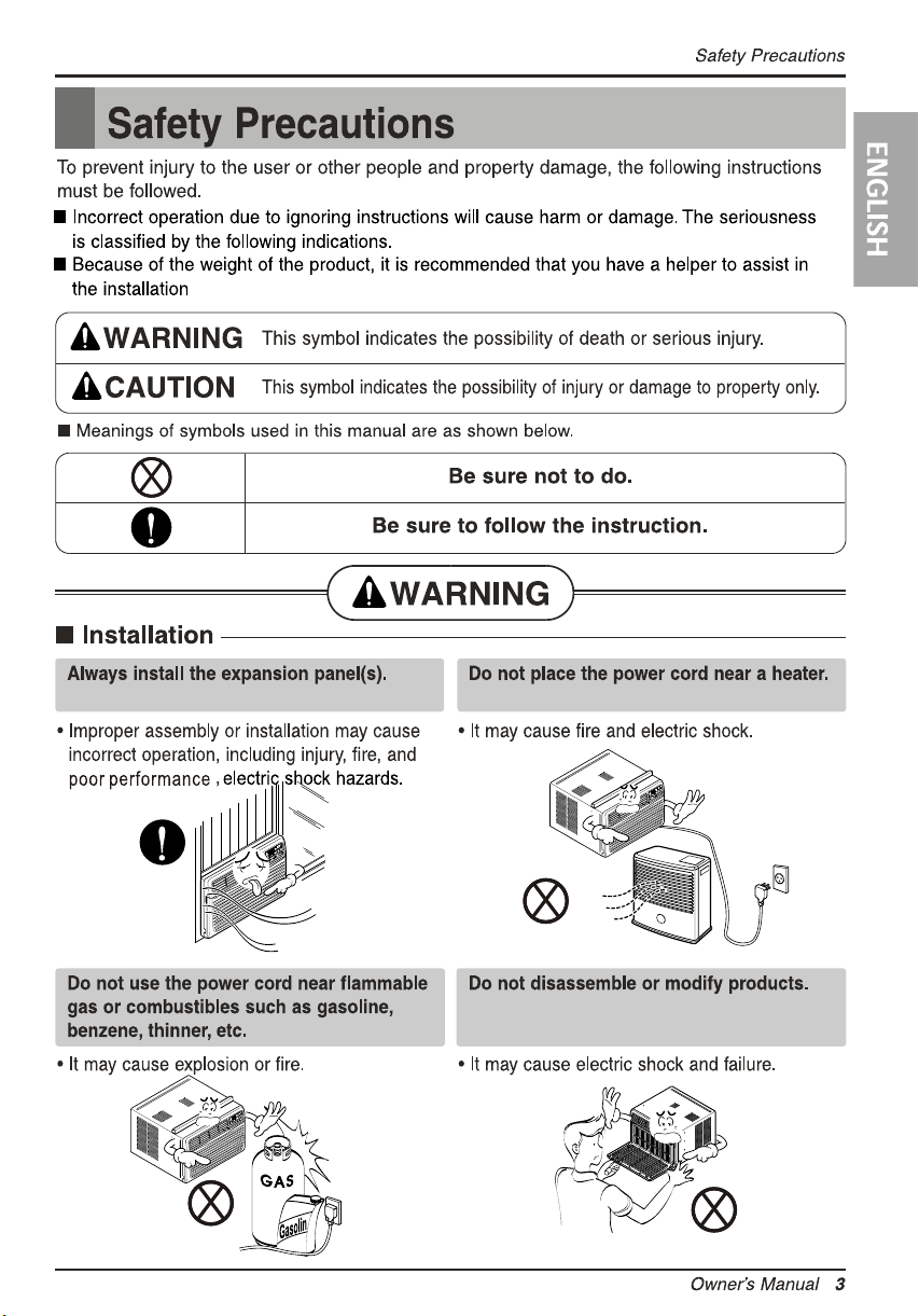
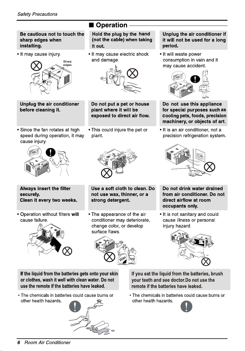
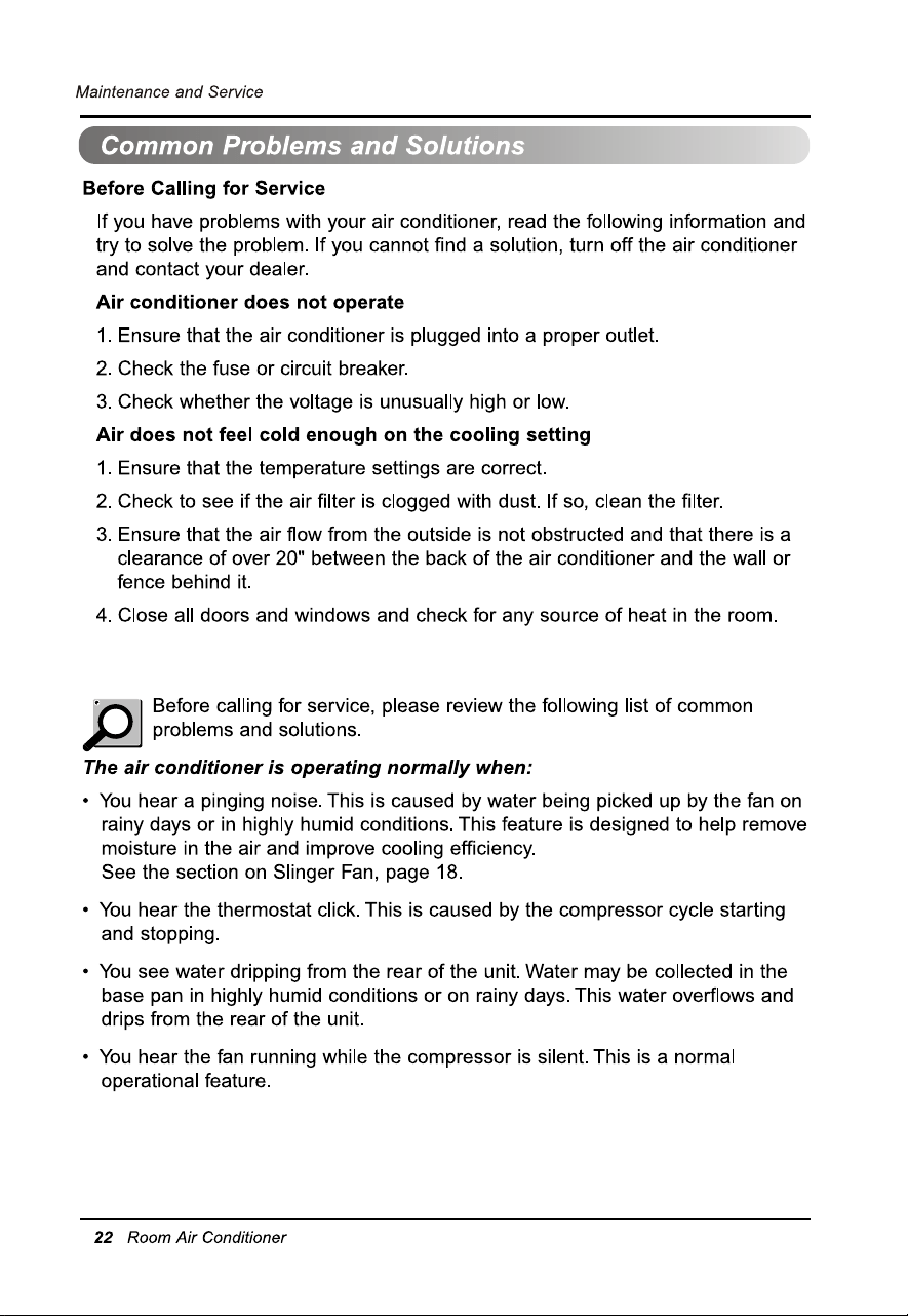
Do not operate the air conditioner if
you smell gas.
Do not operate the air conditioner if
you smell gas.
For inner cleaning, contact an Authorized Service Center or a dealer.
Do not use harsh detergent that causes corrosion or damage on the unit.
Harsh detergent may also cause failure of product, fire, or electronic shock.
13
15
11
14
12
10
9
7
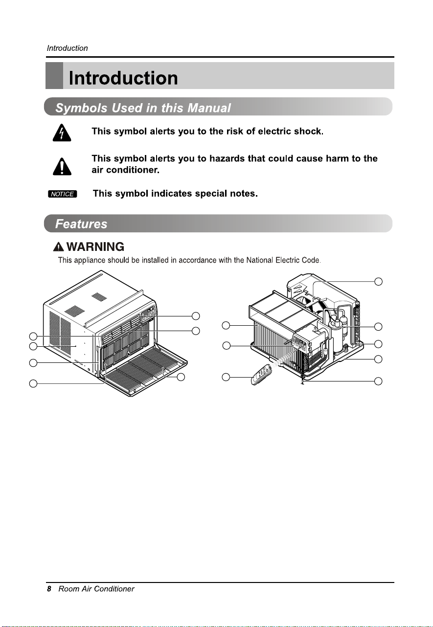
1. CABINET
2. FRONT GRILLE
3. AIR FILTER
4. AIR INTAKE (INLET GRILLE)
5. AIR DISCHARGE
6. VERTICAL AIR DEFLECTOR
(HORIZONTAL LOUVER)
7. EVAPORATOR
8. HORIZONTAL AIR DEFLECTOR
(VERTICAL LOUVER)
9. CONTROL PANEL
10. POWER CORD
11. COMPRESSOR
12. BASE PAN
13. BRACE
14. CONDENSER
15. REMOTE CONTROLLER(OPTIONAL)
4
6
5
8
1
2
3
Use of adapter plugs not pemitted in Canada.
5
4
3
2
1
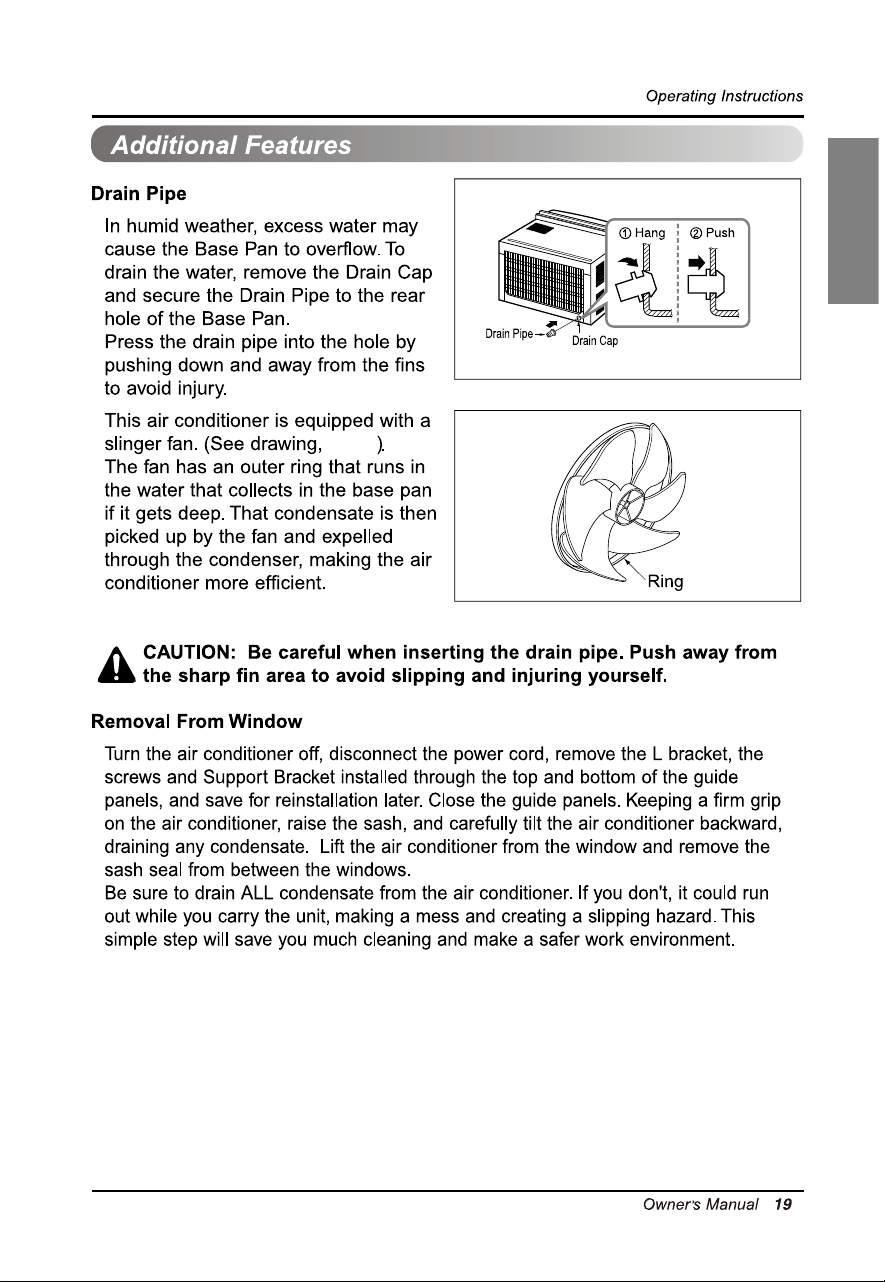
About
Awning
Cooled air
Fence
Over
Heat
radiation
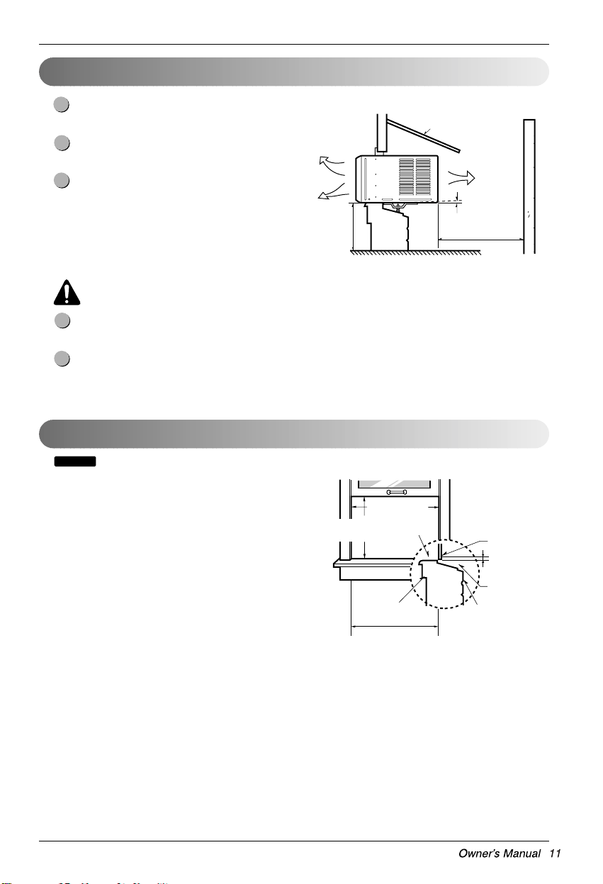
How to Install the Unit
To prevent vibration and noise, make sure the unit
is installed securely and firmly.
Install the unit where the sunlight does not shine
directly on the unit.
The outside of the cabinet must extend outward for
at least 12″ and there should be no obstacles,
such as a fence or wall, within 20″ from the back
of the cabinet because it will prevent heat radiation of the
condenser.
Restriction of outside air will greatly reduce the
cooling efficiency of the air conditioner.
CAUTION: All side louvers of the cabinet must remain exposed to the outside of the
structure.
Install the unit a little slanted so the back is slightly lower than the front (about 1/2″).
This will force condensed water to flow to the outside.
Install the unit with the bottom about 30″ ~60″ above the .level roolf
30″ ~60″
(762mm~1524mm)
1/2″ (12.7mm)
20″ (508mm)
Window Requirements
: All supporting parts should be secured to firm wood, masonry, or metal.
• This unit is designed for installation in standard double
hung windows with actual opening widths from 27″ to 39″.
• The top and bottom window sash must open sufficiently
to allow a clear vertical opening of 16″ from the bottom
of the upper sash to the window stool.
NOTICE
(686mm to 991mm)
Offset
Sill
Exterior
Interior wall
(Without frame curtain)
Stool
(406mm)
(With frame curtain)
(12.7mm to 31.8mm)
min
min
27″ to 39″
16″
23 5/8″(
600mm)
1/2
″ to1 1/4″
Hardware Installation
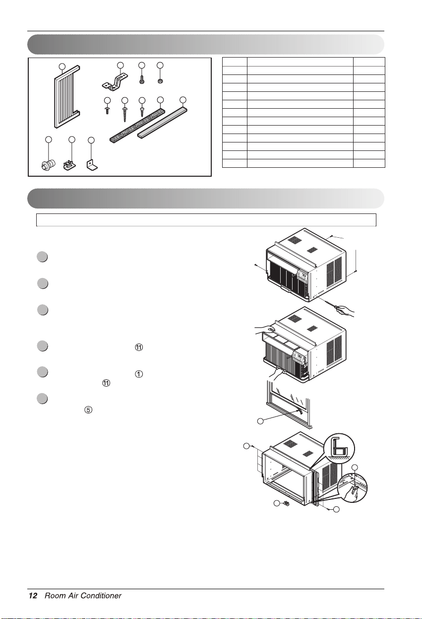
Installation Kits Contents
Suggested Tool Requirements
1
2 3 4
8 10
765
12
119
NO. NAME OF PARTS Q'TY
1 FRAME CURTAIN 2
2 SILL SUPPORT 2
3 BOLT 2
4 NUT 2
5 SCREW (TYPE A) 13
6 SCREW (TYPE B) 3
7 SCREW (TYPE C) 5
8 FOAM-STRIP 1
9 DRAIN PIPE 1
10 FOAM-PE 1
11 FRAME GUIDE 2
12 WINDOW LOCKING BRACKET 1
Shipping
Screws
5
10
(Type A)
11
11
5
PREPARATION OF CHASSIS
SCREWDRIVER(Philips and Flatead), RULER, KNIFE, HAMMER, PENCIL, LEVEL
Remove the screws which fasten the cabinet at both
sides and at the back.
Slide the unit from the cabinet by gripping the base pan
handle and pulling forward while bracing the cabinet.
Cut the window sash seal to the proper length.
Peel off the backing and attach the Foam-PE to the
underside of the window sash.
Insert the Frame Guides
into the bottom of the
cabinet.
Insert the Frame Curtain
into the Upper Guide and
Frame Guides
.
Fasten the curtains to the unit with Type
A screws
.
6
5
4
3
2
1
Hardware Installation
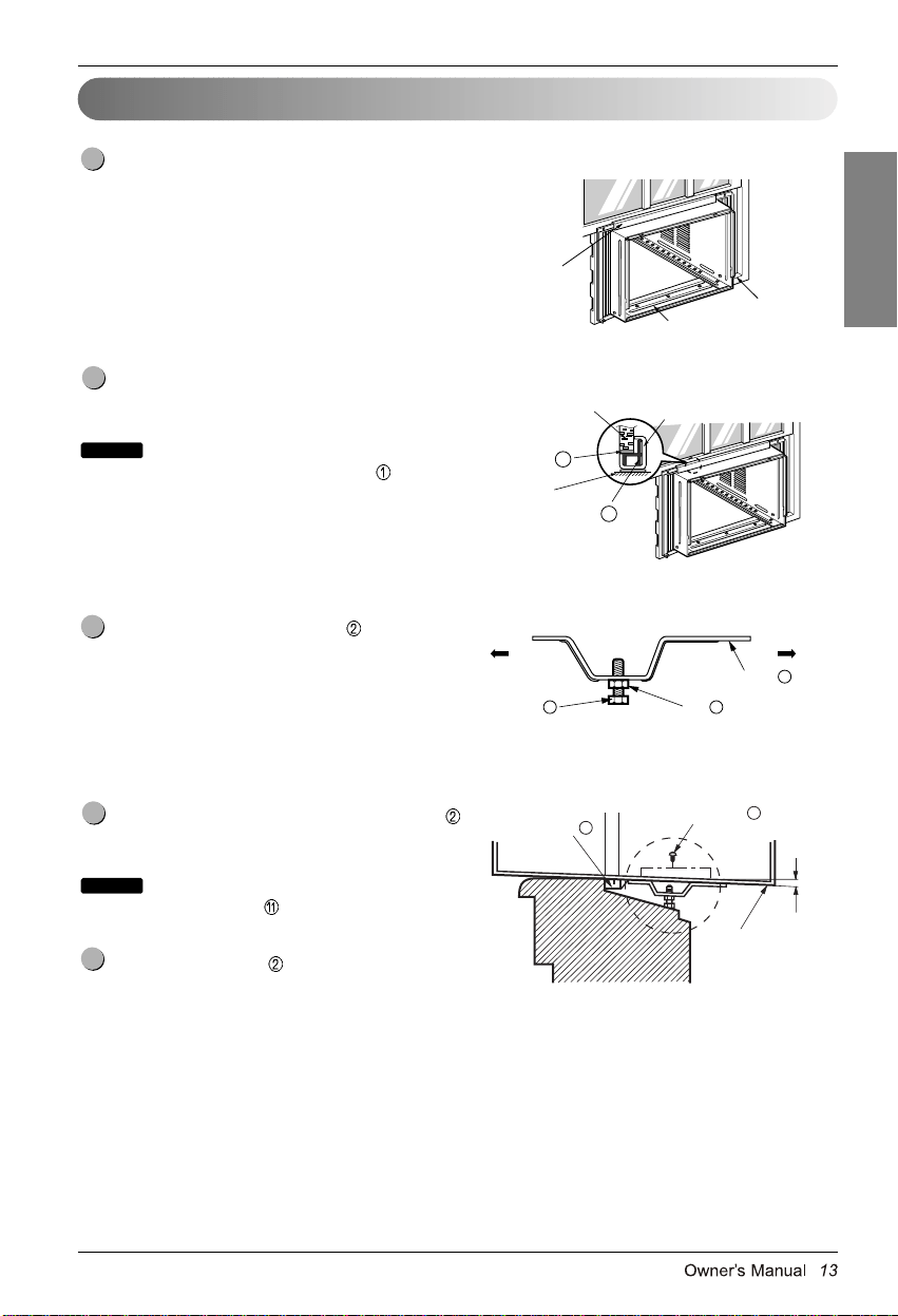
Cabinet Installation
Open the window. Mark a line on center of the
window stool.
Carefully place the cabinet on the window stool and
align the center mark on the bottom front with the
center line marked in the window stool.
Pull the bottom window sash down behind the Upper
Guide until it meets.
: Do not pull the window sash down tightly that
the movement of Frame Curtain is restricted.
Loosely assemble the Sill Support
using the parts
in Fig. 3.
Select the position that will place the Sill Support
near the outer most point on sill (See Fig. 4)
: Be careful when you install the cabinet
(Frame Guides
are broken easily).
Attach the Sill Support
to the cabinet track hole in
relation to the selected position using 2 Type A
screws in each support (See Fig. 4).
5
NOTICE
4
3
NOTICE
2
1
INDOOR OUTDOOR
Sill Support
2
Nut
4
Bolt
3
INDOOR OUTDOOR
Cabinet
Abou t
Frame Guide
11
Screw(Type A)
5
1/2″ (12.7mm)
Upper Guide
Window stool
Front Angle
Window Sash Upper guide
Frame Curtain
1
Foam-pe
Cabinet
Fig. 1
Fig. 2
Fig. 3
Fig. 4
10
ENGLISH
Hardware Installation
Sash track
Front Angle
Screw(Type B)
6
Screw(Type B)
6
Sill Support
2
Sill Support
2
Foam-Strip
8
Fig. 5
Type C
7
Fig. 6
Screw(Type A)
Screw
(Type A)
Power cord
Fig. 7
Fig. 8
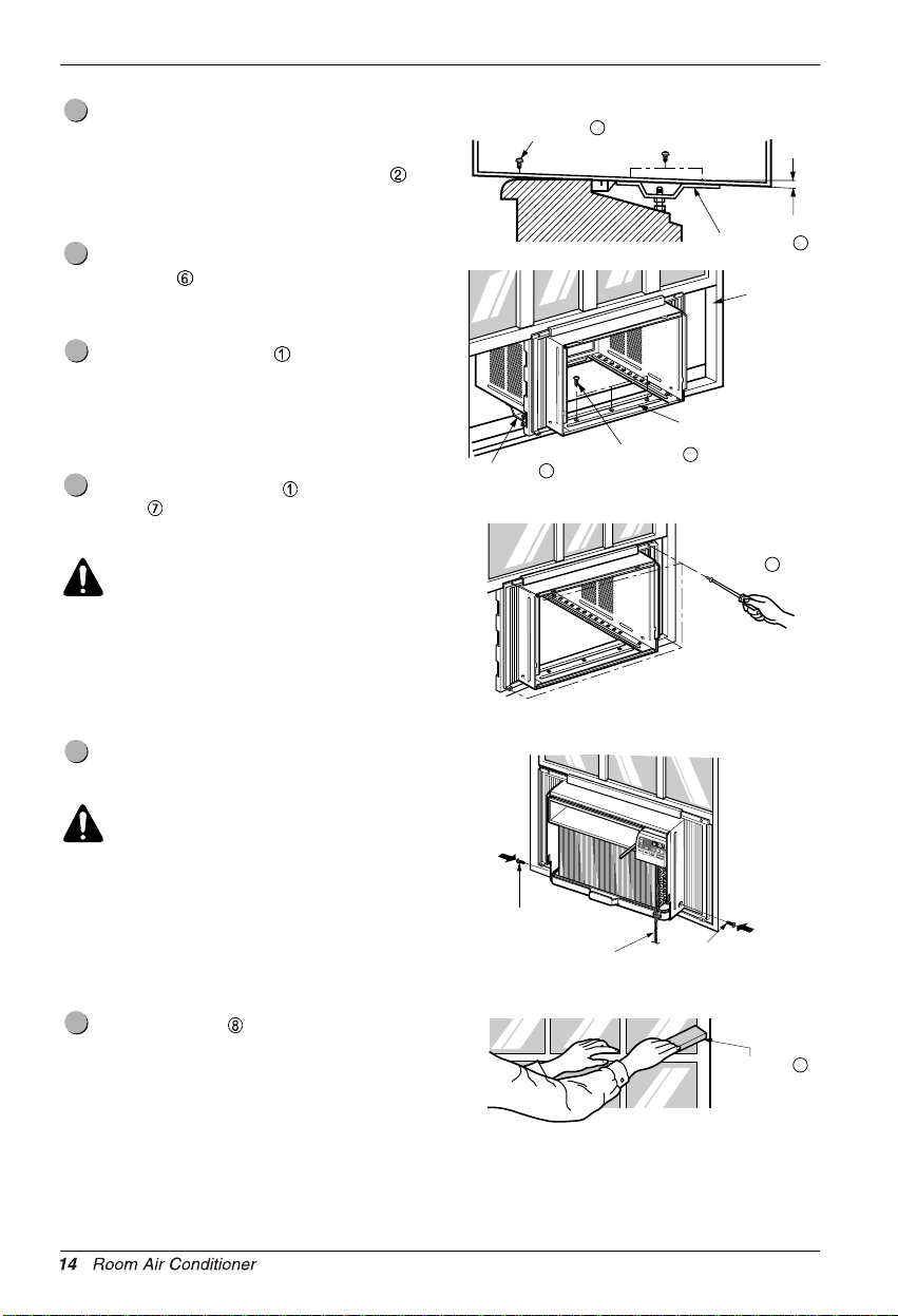
The cabinet should be installed with a very slight tilt
(about 1/2″) downward toward the outside
(See Fig. 5).
Adjust the bolt and the nut of Sill Support
for
balancing the cabinet.
Attach the cabinet to the window stool by driving
the screws
6
Hardware Installation
(Type B: Length 5/8″)
and below.) through the front angle into window
stool.
Pull each Frame Curtain
fully to each window
sash track, and repeat step 2.
Attach each Frame Curtain the window sash using
screws
(Type C). (See Fig. 6)
CAUTION: Do not drill a hole in the bottom
pan. The unit is designed to operate with
approximately 1/2″ of water in bottom pan.
There is no need to add water if the pan is
dry.
Slide the unit into the cabinet. (See Fig. 7)
CAUTION: For security purpose, reinstall
screws (Type A) at cabinet's sides.
Cut the Foam-Strip to the proper length and insert
between the upper window sash and the lower
window sash. (See Fig. 8)
11
10
9
8
7
t uobA
1/2″ (12.7mm)
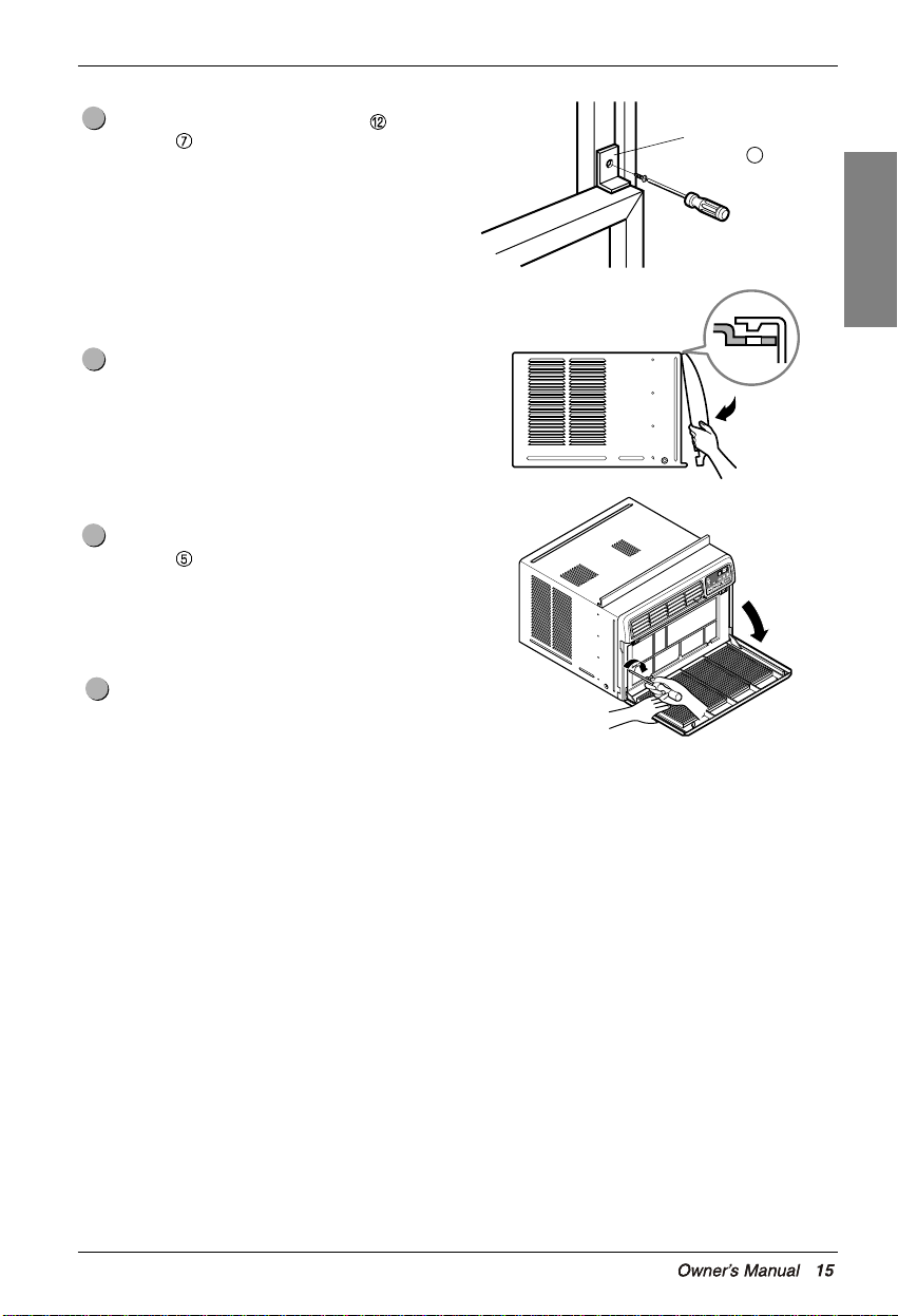
Attach the Window Locking Bracket with a Type
C screw
. (See Fig. 9)
Attach the front grille to the cabinet by inserting the
tabs on the grille into the tabs on the front of the
cabinet. Push the grille in until it snaps into place.
(See Fig. 10)
Pull down the inlet grille and secure it with a Type
A screw
through the front grille. (See Fig. 11)
Window installation of room air conditioner is
now completed. See ELECTRICAL DATA for
attaching power cord to electrical outlet.
15
14
13
12
Window locking
bracket
12
Fig. 9
Fig. 10
Fig. 11
ENGLISH
Hardware Installation
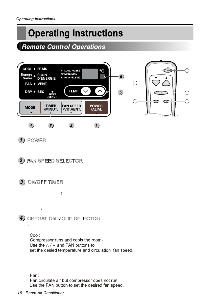
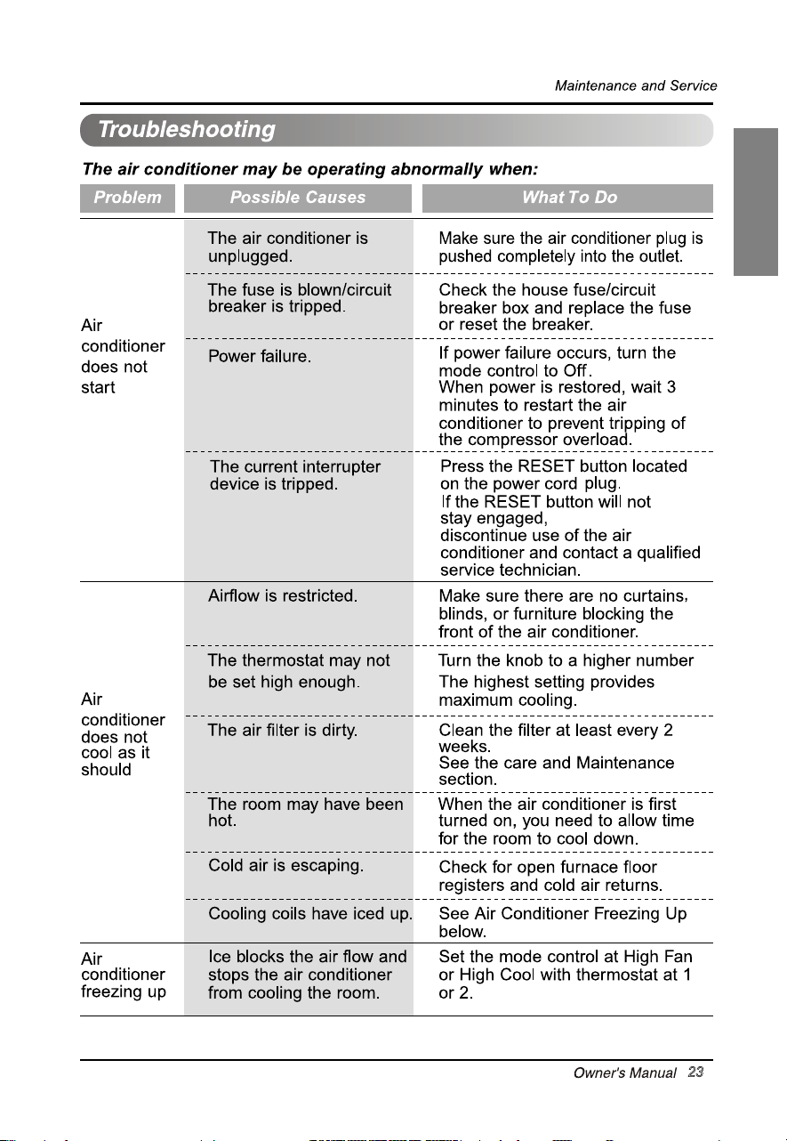
POWER
Operation starts when this button is pressed and stops when you
press the button again.
FAN SPEED SELECTOR
For increased power while cooling,select a higher fan speed.
3 steps:High
―Low―Med.
ON/OFF TIMER
The Timer can be set to start and stop the unit in hourly increments
(up to 24 hours
You will usually use shut-off time while you sleep.
For your sleeping comfort,once timer is set ,the temperature setting will
raise &
after 30min and once again after another 30min.
OPERATION MODE SELECTOR
Energy Saver:
Approximately every 3 minutes the fan will turn on
and check the room air tedetermine of cooling is need.
The fan stops when the compressor stops cooling.
Everytime you push this button,it will toggle between Cool,Energy Saver,Fan
and Dry.
C
Temp
Fan Speed
Timer Mode
1
2
4
3
5
Select dry mode for dry operation.
Dry:dry model is used to remove humidity from the room without additional cooling.
Once the set temperature is reached,the compressor and circulation fan turns off.
Fan speed is pre-set and cannot be adjusted.
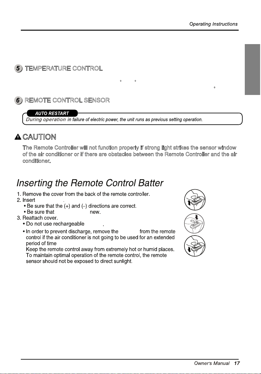
TEMPERATURE CONTROL
The thermostat monitors room temperature to maintain the desired temperature.
The thermostat can be set between
The unit takes an average of 30 minutes to adjust the room temperature by 1 C.
16 C~30 C.
REMOTE CONTROL SENSOR
CAUTION
The Remote Controller will not function properly if strong light strikes the sensor window
of the air conditioner or if there are obstacles between the Remote Controller and the air
conditioner.
y
one
battery
the
battery is
battery
battery
ENGLISH
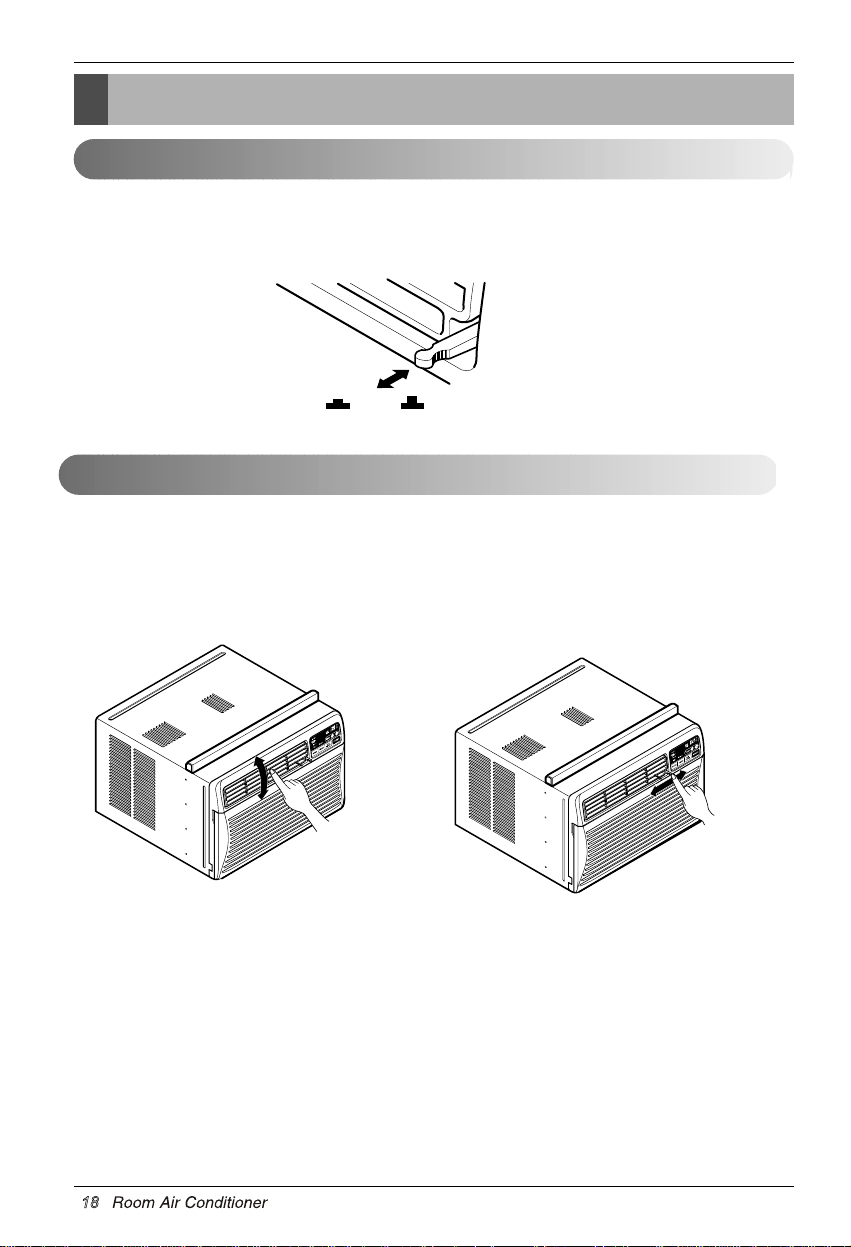
Adjusting horizontal air flow Adjusting vertical air flow
• Adjusting Horizontal Air Flow Direction
Adjusting the vertical louvers left and right will
change horizontal airflow.
• Adjusting Vertical Air Flow Direction
Adjusting the horizontal vane up and down will
change vertical airflow. The vane can be adjusted
by nudging the vane backward or forward.
Adjusting the Air Flow Direction
Operating Instructions
Adjusting the Air Flow Direction
• Recommended orientation of louvers
Adjust louvers to face upwards when cooling to maximize cooling efficiency.
Airflow can be adjusted by changing the direction of the air conditioner's louvers. This can also increase the
cooling efficiency of the air conditioner.
VENTCLOSE
OPEN
Vent Control
For maximum cooling efficiency, CLOSE the vent. This will allow internal air circulation.
OPEN the vent to discharge stale air.
18
below
ENGLISH
ENGLISH
23
ENGLISH
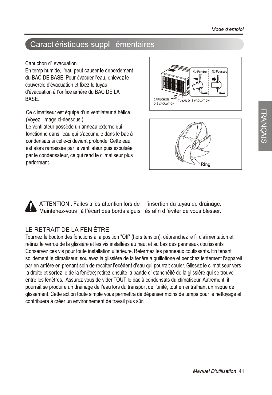
• Contactez l'installateur pour l'installation de cette unité.
42
44
45
Pour éviter des blessures à l'usager ou à d'autres personnes et des dommages à la propriété,
vous devez suivre les instructions ci-dessous.
L’utilisation incorrecte de l’appareil due à la méconnaissance des instructions de ce manuel provoquera
des blessures ou des dommages, dont la gravité est indiquée au moyen des symboles suivants.
En raison du poids du produit, il est recommandé de recourir à un assistant pour l'installation
de cet appareil.
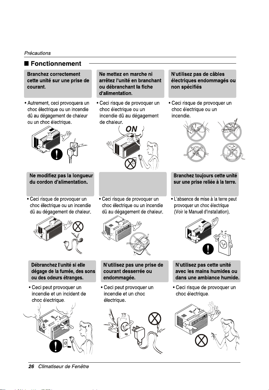
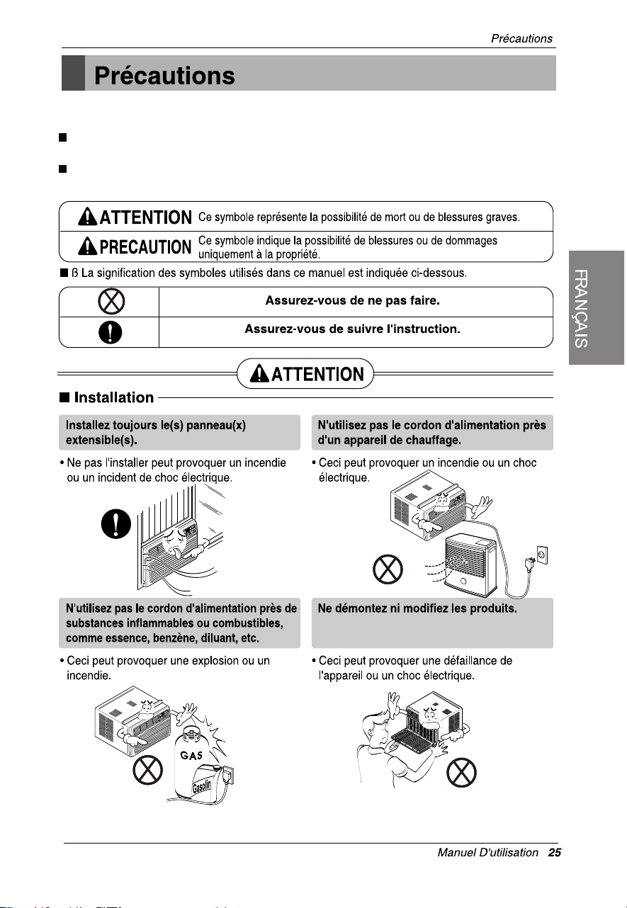
Installez le climatiseur sur un circuit
de sortie dédié. (Référez-vous à la
page 29). Ne partagez pas la prise de
courant avec d'autres appareils.
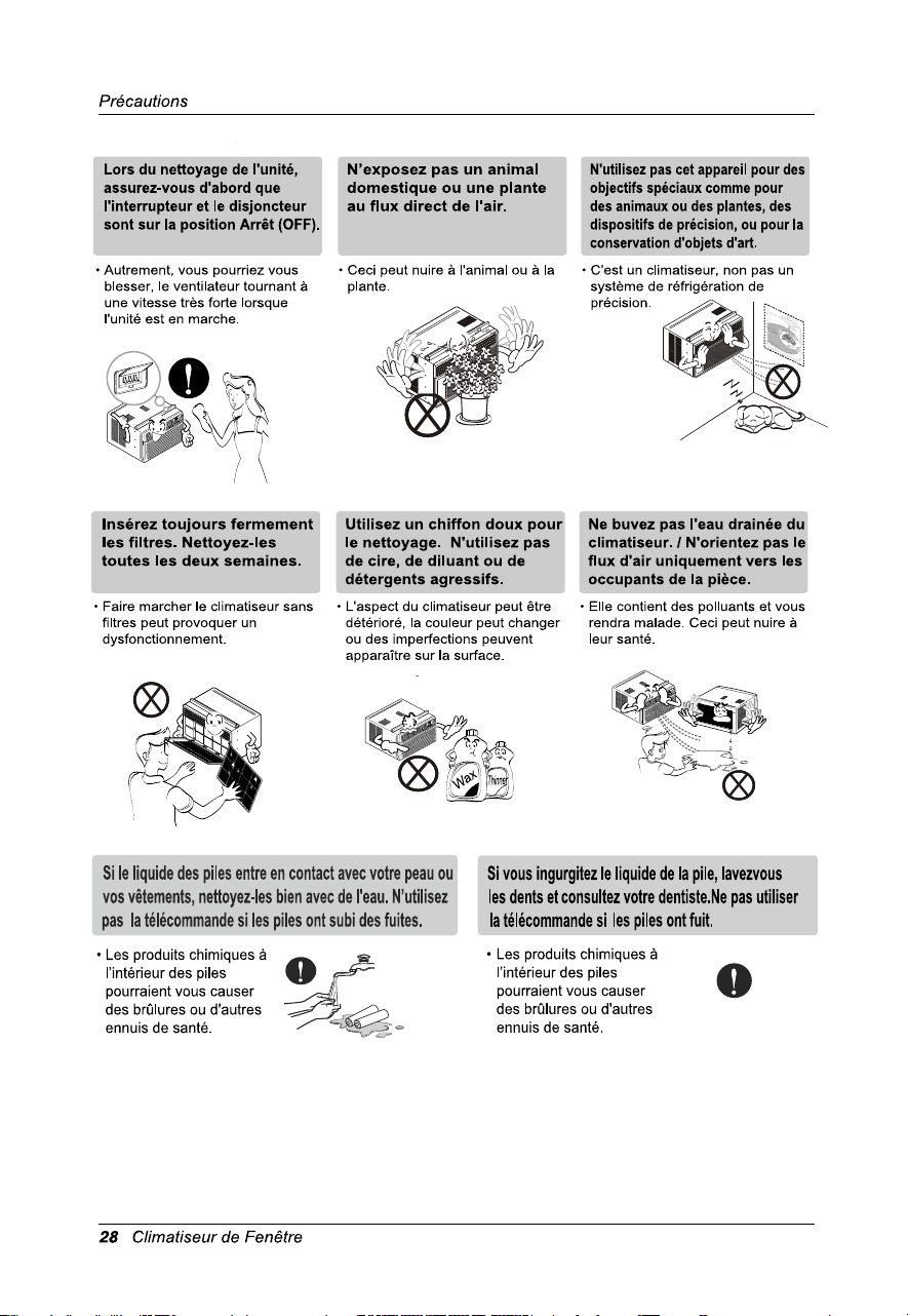
Pour le nettoyage de l’intérieur, veuillez contacter un Centre de Service Agrée ou un
concessionnaire.
N’utilisez pas de détergent puissants qui provoquent la corrosion ou endommagent l’unité.
Les détergents puissants peuvent aussi provoquer des pannes, des incendies ou
des chocs électriques.
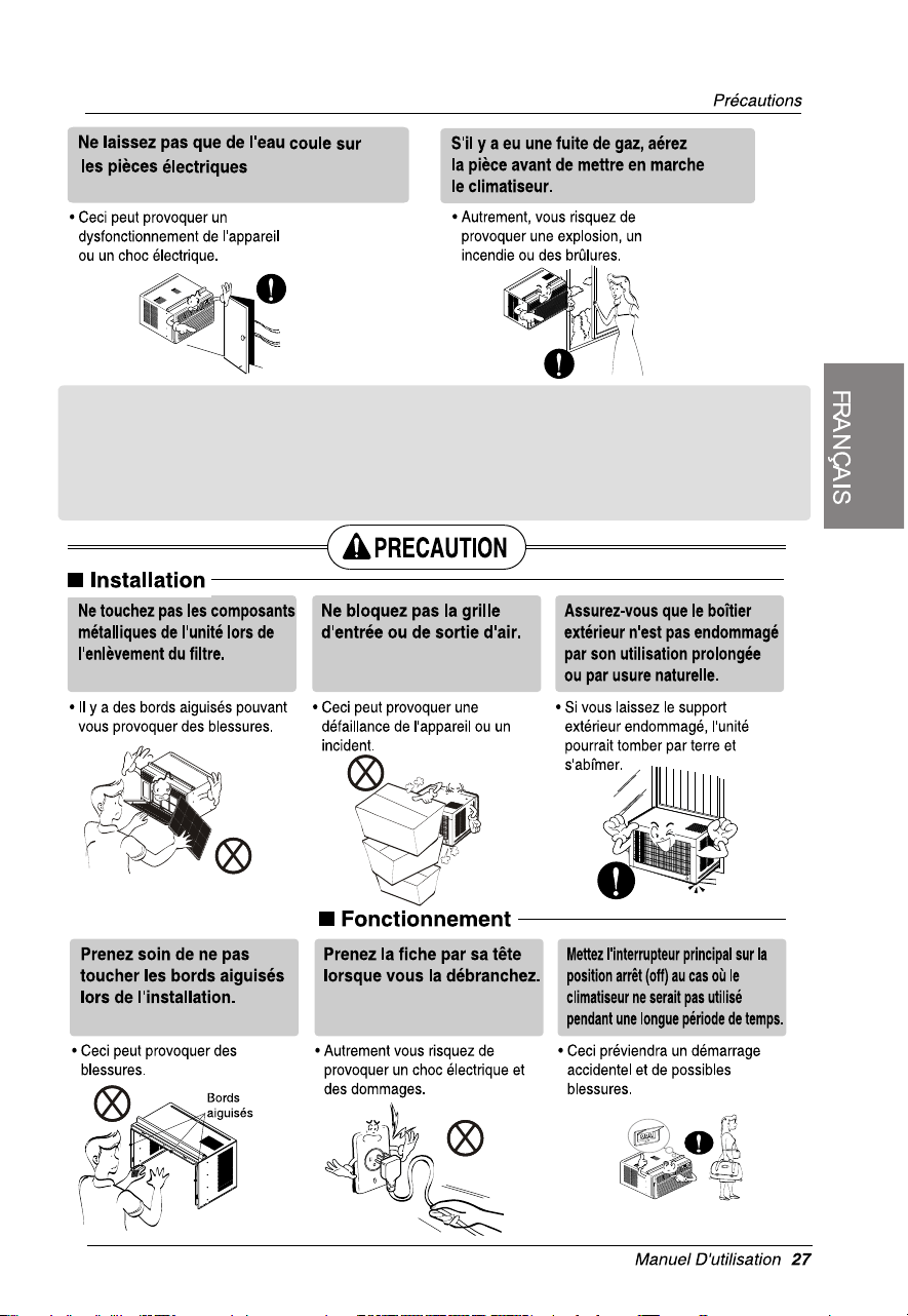
3. Lors du nettoyage de l'unité, assurez-vous d'abord que
l'interrupteur et le disjoncteur sont sur la position Arrêt (OFF). Le ventilateur tourne à une vitesse
très forte pendant que l'unité est en marche. Vous pourriez vous blesser si l'unité est
accidentellement mise en marche alors que vous nettoyez les parties intérieures de l'unité-
13
15
11
14
12
10
9
7
4
6
5
8
1
2
3
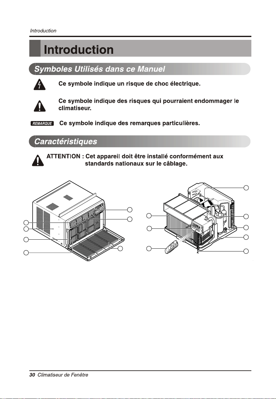
1. BOÎTIER
2. GRILLE AVANT
3. FILTRE À AIR
4. PRISE D'AIRAIR (GRILLE DE PRISE
D'AIR)
5. RETOUR D'AIR
6. DÉFLECTEUR D'AIR VERTICAL
(VOLET HORIZONTAL).
7. ÉVAPORATEUR
8. DÉFLECTEUR D'AIR HORIZONTAL
(VOLET VERTICAL)
9. PANNEAU DE COMMANDE
10. CORDON D'ALIMENTATION
11. COMPRESSEUR
12. RÉCEPTACLE D'EAU
13. ÉQUERRE DE RENFORT
14. CONDENSEUR
15. TÉLÉCOMMANDE(FACULTATIF)
l'utilisation de l'adaptateur se branche pas pemitted
au Canada.
Environ 12.7 mm
~
Auvent
Air refroidi
Clôture
508mm ou plus
Radiation
de chaleur
mm267
mm4251
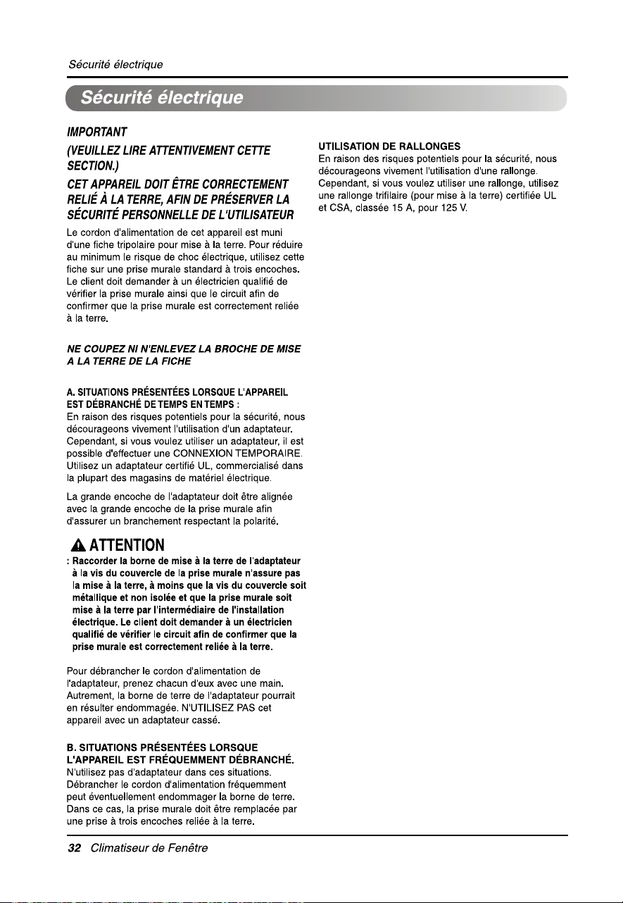
Installation de l’appareil
Installez l'appareil solidement et sécuritairement de
manière à prévenir la présence de vibrations et bruits.
Installez l'appareil de manière à ne pas l'exposer
directement aux rayons du soleil.
Le boîtier doit sortir d'au moins 305mm à l'extérieur et
aucun obstacle du genre clôture ou mur doit se
situer à moins de 508mm de l'arri è re du boîtier car cela
nuira à la radiation de chaleur du condenseur. La
capacité de refroidissement du climatiseur sera
sérieusement affectée par une restriction
d'alimentation d'air extérieur.
PRECAUTION: Toutes les ailettes latérales du
boîtier doivent se situer à l'extérieur du bâtiment.
Installez l'appareil légèrement incliné vers l'extérieur (environ 12.7mm).
Cela permettra à l'eau de condensation de s'écouler vers l'extérieur.
Installez l'appareil de man
ièreà ce que sa surface inférieure se situe entre 30" et 60" (762mm et 1524 mm)
au-desssus du niveau du plancher.
5
4
3
2
1
Installation du matériel
686mm
à
991mm
Décalage
Seuil
Extérieur
Mur intérieur
600mm
(Sans volets d'étanchéité)
Rebord
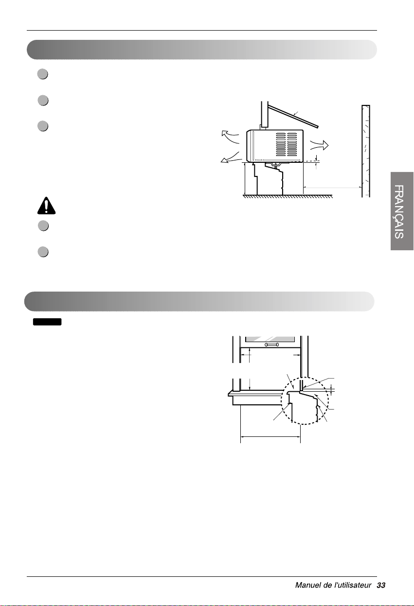
AVIS
12.7mm to 31.8mm
min.
min.
• Cet appareil est conçu pour installation
dans des fenêtres à guillotine normales de
largeur variant entre 686mm et 991mm.
• Les châssis supérieur et inférieur de la
fenêtre doivent offrir une ouverture verticale
d'au moins 406mm entre le bas du châssis
supérieur et le rebord de la fenêtre.
406mm
(volet d'étanchéité inclus)
Dimensions de fenêtre minimales
:
Tous les éléments d'installation doivent être fixés à du bois, de la maçonnerie ou du métal sain et solide.
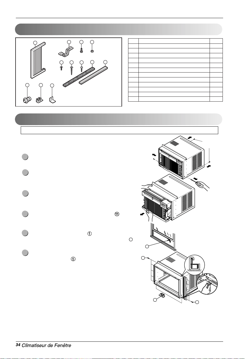
Contenu du nécessaire d’installation
Outils recommandés
1
2 3 4
8 10
765
12
119
NO. NOM DES PIÈCES QTÉ
1 VOLET D'ÉTANCHÉITÉ 2
2 SUPPORT DE SEUIL 2
3 BOULON 2
4 ÉCROU 2
5 VIS (TYPE A) 13
6 VIS (TYPE B) 3
7 VIS (TYPE C) 5
8 BANDE EN MOUSSE 1
9 TUYAU DE DRAINAGE 1
10 JOINT D'ÉTANCHÉITÉ EN MOUSSE 1
11 DISPOSITIF DE GUIDAGE DU CADRE 2
12 ÉTRIER DE VERROUILLAGE DE FENÊTRE 1
10
Vis
d'expédition
5
11
5
PRÉPARATION DU CADRE
Déposez les vis situées de part et d'autre et à l'arrière du
boîtier.
Tout en retenant le boîtier, glissez l'appareil hors du
boîtier en tirant vers l'avant sur la poignée du réceptacle
d'eau.
Coupez le joint d'étanchéité en mousse à la longueur
requise. Pelez le ruban détachable du joint et collez-le
sur la face inférieur du châssis inférieur.
Insérez les dispositifs de guidage du cadre
dans la
partie inférieure du boîtier.
Insérez les volets d'étanchéité dans le rail de guidage
supérieur et dans les dispositifs de guidage du cadre
Fixez les volets d'étanchéité à l'appareil à l'aide de
quatre vis de type A
.
6
5
4
3
2
1
11
TOURNEVIS (Philips etT Flatead), RÈGLE, COUTEAU, MARTEAU, CRAYON, NIVEAU.
Installation du matériel
(Type A)
INTÉRIEUR EXTÉRIEUR
Support de seuil
2
Écrou
4
Boulon
3
INTÉRIEUR EXTÉRIEUR
Boîtier
Environ 1/2" (12.7 mm)
Dispositif de
guidage de cadre
11
Vis (Type A)
5
Rail de guidage
supérieur
Rebord de fenêtre
Angle avant
Châssis de fenêtre
Rail de guidage supérieur
Volet d'étanchéité
1
10
Joint d'étanchéité
en mousse
Boîtier
Fig. 1
Fig. 2
Fig. 3
Fig. 4
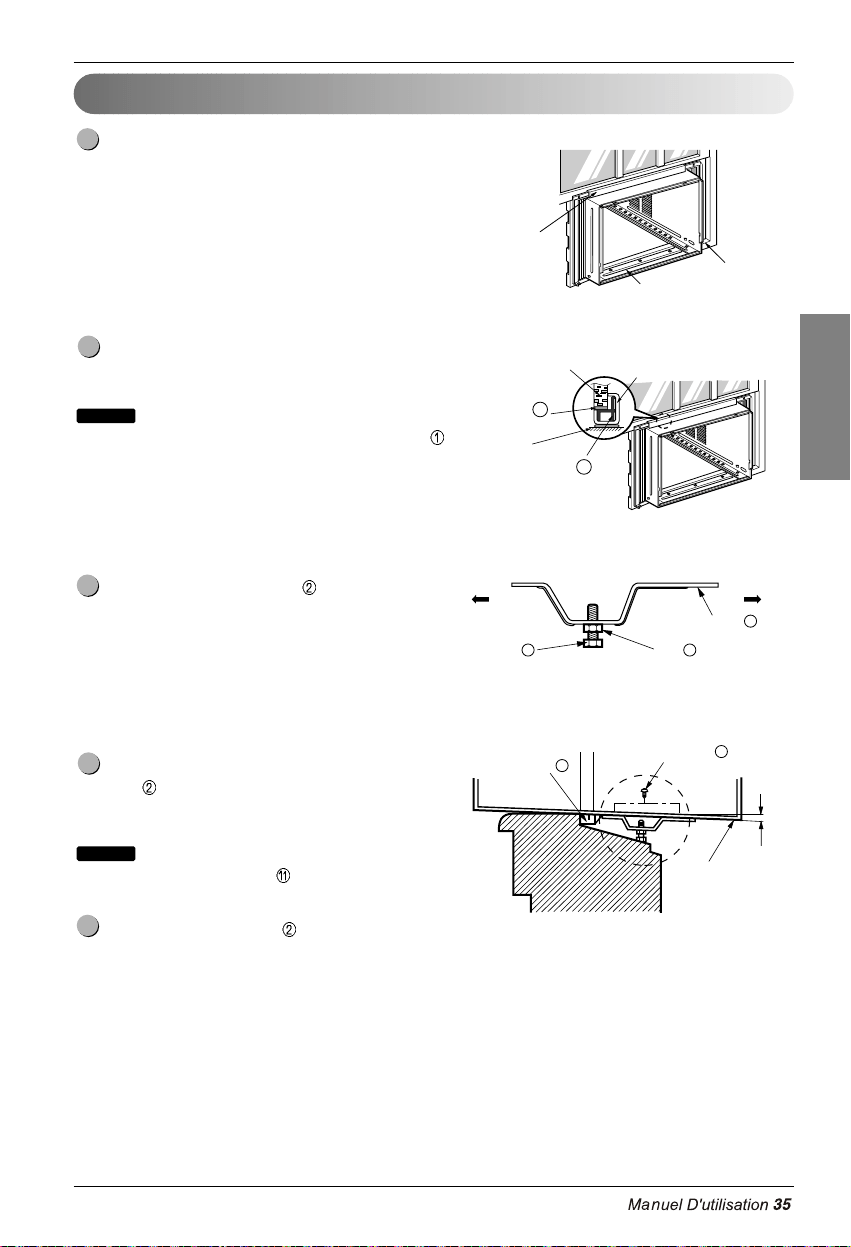
Installation du boîtier
Ouvrez la fenêtre. Tracez une ligne au centre du
rebord de fenêtre.
Placez le boîtier soigneusement sur le rebord de
fenêtre et alignez le repère central de sa portion
inférieure avant avec la ligne tracée sur le rebord de
fenêtre.
Abaissez le châssis inférieur à l'arrière du rail de
guidage supérieur jusqu'à ce qu'ils fassent
Ne serrez pas le châssis de fenêtre au point où cela
nuira au mouvement des volets d'étanchéité
.
Assemblez le support de seuil
à l'aide des pièces
illustrées dans la fig. 3 mais ne les serrez pas. 3.
Choisissez l'emplacement qui situera le support de
seuil
à l'emplacement le plus à l'extérieur du seuil
(Voyez la fig. 4).
Installez le boîtier avec précaution (les dispositifs
de guidage de cadre peuvent briser).
Fixez les supports de seuil
aux orifices de guidage
du boîtier, en fonction de l'emplacement sélectionné,
à l'aide de 2 vis de type A pour chaque support
(Voyez la fig.4).
5
REMARQUE
4
3
REMARQUE
2
1
FRANÇAIS
Installation du matériel
2
Coulisse
de chassis
Angle avant
Environ 12.7mm
Vis (Type B)
6
Vis (Type B)
6
Support de seuil
2
Support de seuil
Bande
en mousse
8
Fig. 5
Type C
7
Fig. 6
Fig. 7
Fig. 8
Vis (Type A)
Cordon
d'alimentation
Vis (Type A)
Installez le boîtier avec une inclinaison d'environ
1/2" (12.7 mm) vers l'extérieur (Voyez la fig. 5).
Réglez l'écrou et le boulon des supports de seuil
de manière à équilibrer le boîtier.
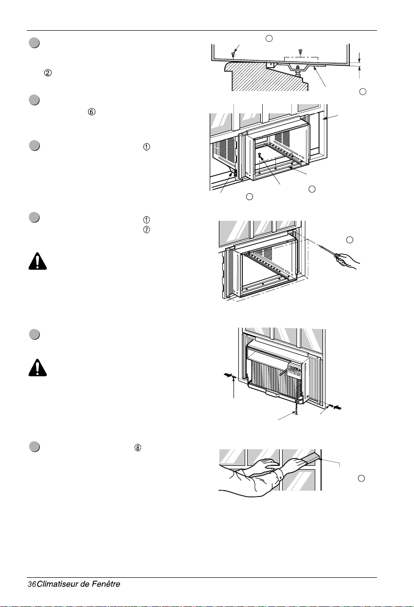
Fixez le boîtier au rebord de fenêtre à l'aide de
vis de type B
(16 mm [5/5"] de long) passant à
travers de l'angle avant du boîtier et se logeant
dans le rebord de fenêtre.
Tirez chaque volet d'étanchéité entièrement
contre chaque coulisse de châssis et répétez
l'étape 2.
Fixez chaque volet d'étanchéité à la coulisse de
châssis à l'aide de vis de type C . (Voyez la fig. 6.)
PRECAUTION: Ne percez pas de trous dans le
réceptacle d'eau. L'appareil est conçu pour
fonctionner avec environ 1/2" (12.7 mm) d'eau
présent dans le réceptacle d'eau. S'il n'y a pas
d'eau dans le réceptacle, il n'est pas
nécessaire d'en ajouter.
Glissez l'appareil dans le boîtier. (Voyez la fig. 7)
PRECAUTION: Pour des raisons de sécurité,
réinstallez les vis latérales (Type A) du boîtier.
Coupez la bande en mousse
à la longueur
appropriée et insérez-la entre les châssis supérieur
et inférieur de la fenêtre. (Voyez la fig. 8)
11
10
9
8
7
6
Installation du matériel
Étrier de verrouillage
de fenêtre
12
Fig. 9
Fig. 10
Fig. 11
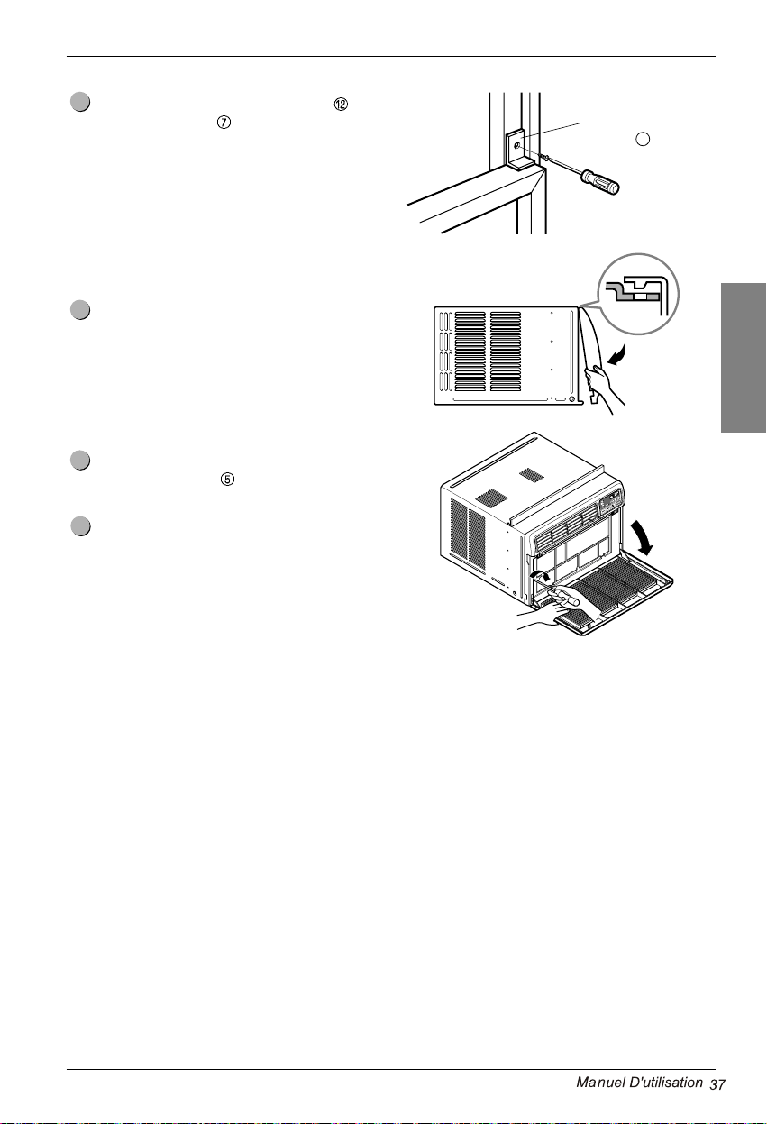
Fixez l'étrier de verrouillage de fenêtre à l'aide
d'une vis de type C
. (Voyez la fig. 9)
Fixez la grille avant au boîtier en en insérant les
languettes de la grille dans les encoches situées à
l'avant du boîtier. Poussez la grille jusqu'à ce que
vous l'entendiez cliquer en place. (Voyez la fig.10)
Abaissez la grille de prise d'air et et fixez-la à l'aide
d'une vis de Type A
passant à travers de la
grille. (Voyez la fig. 11)
L'installation du climatiseur de pièce est
maintenant complétée. Pour les détails de
branchement du cordon d'alimentation à une
prise de courant murale, veuillez vous reporter
à SPÉCIFICATIONS ÉLECTRIQUES.
15
14
13
12
FRANÇAIS
Installation du matériel

POWER
SÉLECTEUR DE RÉGIME DU VENTILATEUR
Pour un refroidissement accru, réglez le ventilateur à un
régime supérieur.
3 niveaux : High → Low→ Med.
4
MINUTERIE ACTIVATION/DÉSACTIVATION
La minuterie peut être réglée pour l'activation/désactivation de l'appareil à intervalles
de une heure (jusqu'à 24 heures).
C
1
C
TEMPERATURE
VITESSE DU VENTILATEUR
MINUTEUR MODE
1
2
4
3
5
P
SÉLECTEUR DE MODE DE FONCTIONNEMENT
Chaque fois que vous appuyez sur ce bouton, il va basculer entre FRAIS, ECONOMIE
D’ENERGIE, VENTILLATEUR et SEC.
Frais: Le compresseur est en marche et rafraîchi la pièce.
Utilisez les boutons et VENTILLATEUR pour régler la température
à votre convenance ainsi que la vitesse du ventilateur de recirculation.
Ventilateur: Le ventilateur fait recirculer l’air, mais le compresseur ne fonctionne pas.
Utilisez le bouton VENTILLATEUR pour régler la température
à votre convenance.
1
2
3
Sec:
Le modèle sec est employé pour enlever l’humidité de la pièce sans
y apporter de l’air froid supplémentaire.
Une fois la température réglée atteinte, le compresseur et le ventilateur de
recirculation s’arrêtent.
Pour le fonctionnement en mode d'économieénergétique.
Economie D’energie:
Appuyez sur cette touche pour activer l'appareil et appuyez de nouveau pour le désactiver.
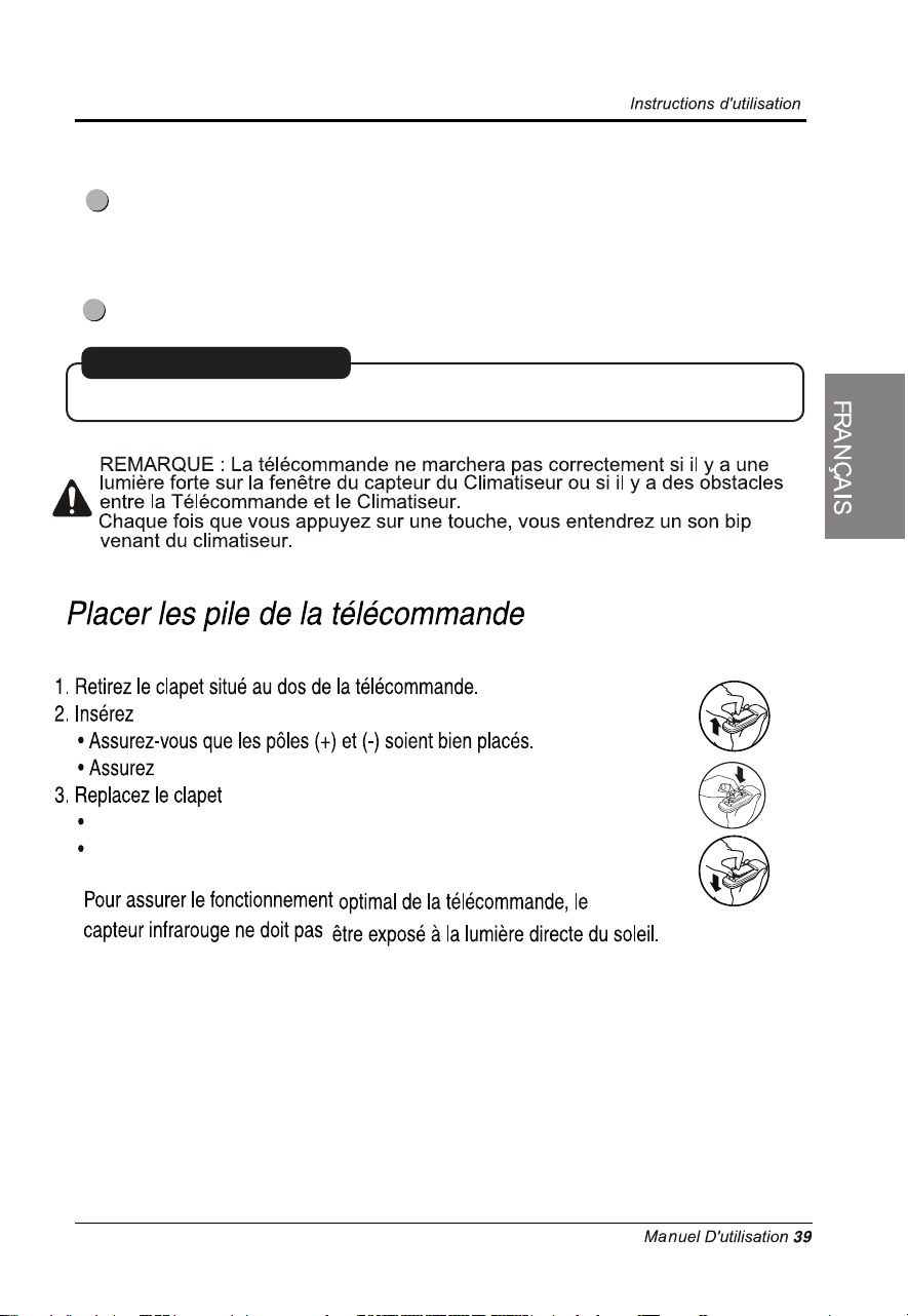
CAPTEUR DE SIGNAL DE TÉLÉCOMMANDE
6
AUTO-REMISE EN MARCHE
En cas de manque de courant, l’unité reprend ses réglages précédents de fonctionnement.
5
CONTRÔLE DE TEMPÉRATURE
Le thermostat surveille la température de la pièce afin d'y
maintenir la température souhaitée.
Vous pouvez régler le thermosat entre 16°C~30°C.
Cet appareil ne requiert qu'environ 30 minutes pour
changer la température de la pièce de 1°C.
une batterie.
pas de batterie est neuve.
N’utilisez pas de batterie rechargeable.
Afin d’éviter la décharge, retirez la batterie de la télécommande
si le climatiseur ne va pas être utilisé pendant une longue période.
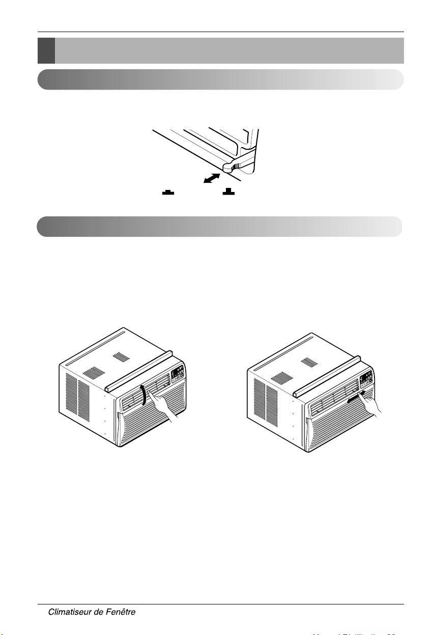
FERMÉ VENTILATION OUVERT
Commande de l’orifice de ventilation
Pour une efficacité maximum du refroidissement, fermez l'ORIFICE DE VENTILATION. Ceci activera la
circulation de l'air de la pièce. OUVREZ l'orifice de ventilation afin d'évacuer l'air vicié.
Réglage de l’orientation du débit d’air
Vous pouvez régler le débit d'air en changeant l'orientation des volets du climatiseur. Cela peut également
améliorer l'efficacité de refroidissement du climatiseur.
• Orientation recommandée des volets
En mode refroidissement et afin d'en améliorer le rendement, orientez les volets vers le haut.
Réglage du dé Rlatnoziroh ria'd tib églage du débit d'air vertical
•
Réglage de l'orientation horizontale du débit d'air
Le réglage des volets verticaux vers la gauche et la
droite changera l'orientation du débit d'air
horizontal.
• Réglage de l'orientation verticale du débit d'air
Le réglage du déflecteur d'air horizontal vers le haut
et le bas changera l'orientation du débit d'air
vertical. L’ailette peut être ajustée en poussant
celle-ci vers la partie de devant ou vers l’arrière.
Réglage de l'orientation du débit d'air
Mode d'emploi
40
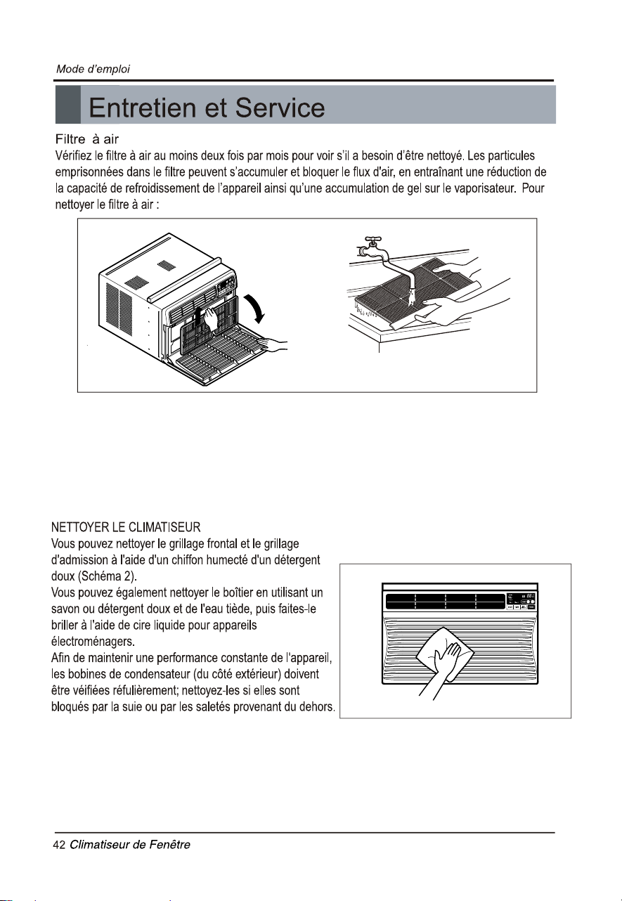
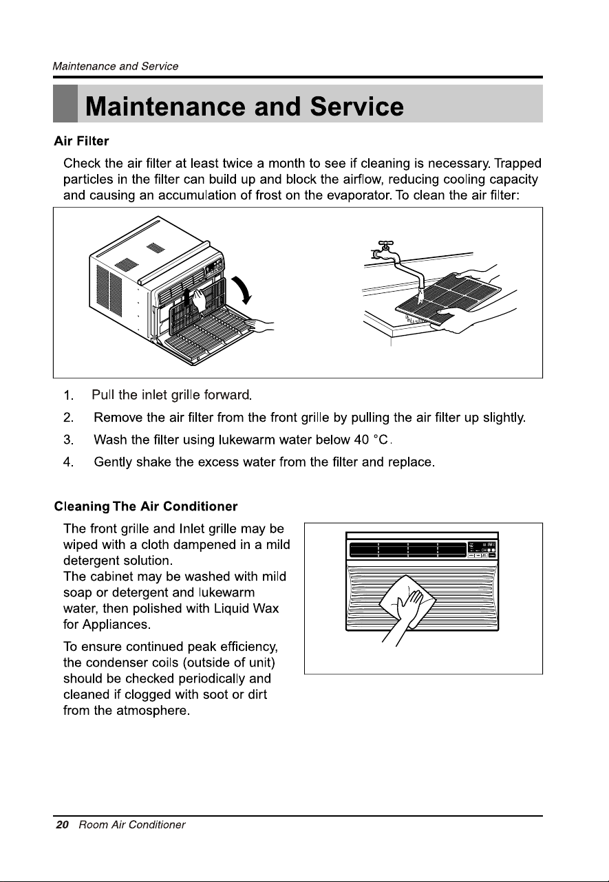
1. Ouvrez la grille interne vers le bas en retirant sa partie supérieure.
2. Remueva el filtro de aire de la parrilla frontal halando el filtro suavemente hacia arriba.
3.
4. Rincez et secouez doucement l'eau du filtre et laissez-le sécher complètement avant de la
remettre.
Lavez le filtre à air à l’eau tiède (au dessous de 40 C (104 F)).
° °
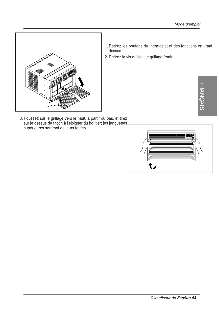
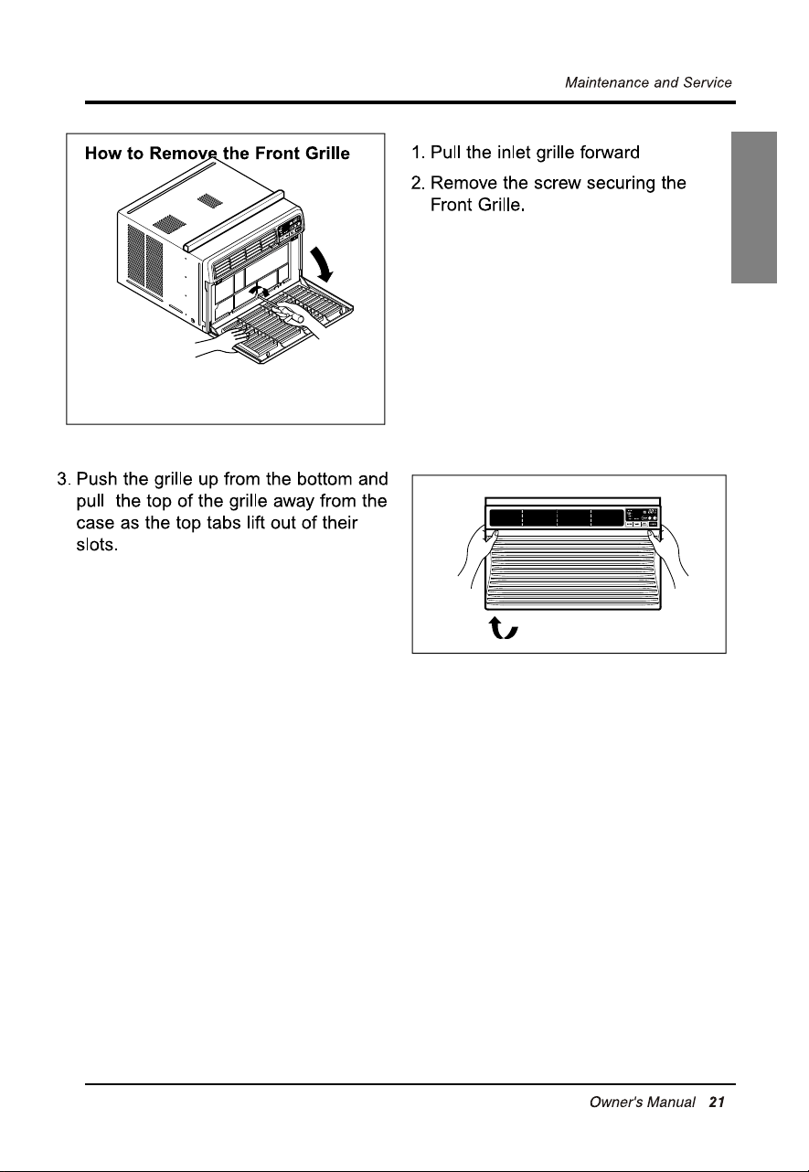
COMMENT ENLEVER LE GRILLAGE FRONTAL
Le disjoncteur intégré de
circuit a basculé.
Appuyez sur le bouton RESET (remise en circuit)
de la fiche du climatiseur. Si le bouton RESET
(remise en circuit) ne reste pas enfoncé,
débranchez votre climatiseur et appelez un
technicien de service qualifié.
45

CEQUIESTCOUVERTPARLAGARANTIE
Si le climatiseur de pièce LG présente un vicede matièreou de fabrication dansdes conditions normales d’utilisation ménagère pendant la
périodedegarantieindiquéeci‐dessous,LG,àsonchoix,répareraouremplaceraleproduit.Cettegarantielimitéen'estoffertequ'àl'acheteur
au détail d'
origine du produit, ne peut pas être assignée ni transféréeà un acheteur ou un utilisateur subséquent et ne s'applique que si le
produitaétéachetéparl'entremised'unrevendeuroudistributeuragrééLGet
utiliséauCanada.
Note : Les produits de rechange oules pièces réparéespourront être ne
ufsou remisà neuf à l'usine et seront garantis pour le restant dela
périodedegarantieoriginaleduproduit ouquatre‐vingt ‐dix(90)jours,selonlapluslonguedespériodes.Veuillezconserverlebondecaisseou
de livraison daté comme preuve de date d'achat aux fins de la garantie (vous pou
rriez avoir à en fournir une copie à LG ou à un de ses
représentantsautorisés).
DURÉEDELAGARANTIE:
1anàcompterdela
dated'achat:touteslespiècesinternes/fonctionnellesetlamain‐d'oeuvre.
EXÉCUTIONDUSERVICE:Serviceàdomicile
Lese
rviceàdomicile sera assurépendantla période degarantiesi un telserviceestoffert auCanada.Leserviceà domicilepeut ne pas être
offertdanscer
tainesrégions.Pourobtenirunserviceàdomicile,leproduit doitsetrouveràunendroitaccessibleetsansobstructionpourle
personneld'entretien.Silaréparationnepeutpasêtreeffectuéeaumomentdelavisiteàdomicile,ilpourraêtrenécessairederetirer,réparer
etretournerlep r oduit. Sileservice àdo
micilen'estpasoffertdansvotrerégion,LGpourra,àsonchoix,opterdedéfrayer letransportaller‐
ret
ourduproduitàuncentredeserviceagréédeLG.
CEQUELAGARANTIELIMI
TÉENECOUVREPAS
1. Lesservicesdelivraison,deramassageoud'installationdu
produitetd'instructionsursonutilisation.
2. Leremplacementdefusiblesouleré enclenchementde
disjoncteurs,lamodificationducâblageoudelaplomberieou
lamodi
ficationdel'installationduproduit,audomicile.
3. Lesdommagesoulespannescaus
ésparlesfuites,lebrisou
legeldetuyauxd'eauoudetuyauxdedrainage,l'interruption
del'alimentationeneauouunmauvaisapportd'air.
4. Lesdommagesoulespannescaus
ésparunaccident,la
vermine,lafoudre,levent,unincendie,uneinondationouun
actefortuit.
5. Lesdommagesoulespannescausésparmauvaiseutilisation,
usageabusif,mauvaiseinstallation,réparationouentretien.
Lamauvaiseinstallationenglobel'utilisationdepiècesnon
approuvéesounonspécifiéesparLG.
6. Lesdo
mmagesoulespannescausésparunemodi ficationnon
autoriséeduproduit.
7. Lesdommagesoulespannescausésparl'applicationd'un
courantoud'unetensionélectriqueinappropriéeoule
manqueàrespecterlecodedeplomberie.
8. Lesdommagesd'apparencecommeleséraflures,les
bosselures,l'écaillageoutoutautredommageaufiniàmoi
ns
quecedommagesoitcauséparunvicedematièreou
de
fabricationetestrapportéàLGdanslessept(7)jours
ouvrablessuivantladatedelivraison.
9. Lesdommagesoulespiècesmanquantes à unproduitde
plancher,enboîteouverte,àrabai
souremisàneuf.
10. Unproduitdontlenumérodesérieoriginal
del'usineaété
éliminé,falsifiéoumodifiéd'unefaçonquelconque.
11. Lesréparationsquandleproduitestutiliséd'unefaçonautre
quel'usageménagernormal(ex.:location,usagecommercial,
bureauxouinstallationsrécréatives)oud'un
efaçoncontraire
auxdirectivesdanslemanueldel'utilisateur.
12. Leretrait
etlaréinstallationd'unproduitinstalléàunendroit
inaccessible.
CETTEGARANTIEREMPLACETOUTEAUTREGARANTIEEXPRESSEOUIMPLICITEYCOMPRIS,SANSLIMITE,LAGARANTIEDEBONNEVENTEET
D'APTITUDEÀPRODUIREUNETÂ CHEPARTICULIÈRE.SIUNEGARANTI
EIMPLICITEQUELCONQUEESTREQUISEPARLALOI,CETTEGARANTIE
SERAD'UNE DURÉE ÉGALEÀLADURÉEINDIQUÉECI‐HAUT.LARÉPARATIONOU LE REMPLACEM
ENTOF FERT AU TITREDECETTE GARANTIE
REPRÉSENTE LE REMÈDE EXCLUSIF AU CLIENT. NI LE FABRICANT NI SON DISTRIBUTEUR CANADIEN NE PEUT ÊTRE TENU RESPONSABLE DE
QUELQUE DO
MMAGE INDIRECT, FORTUIT, CONSÉQUENTIEL, SPÉCIAL OU PUNITIF QUE CE SOIT, Y COMPRIS, SANS LIMITE, LA PERTE DE
REVENUSOUDEPROFITSOUTOUTAUTREDOMMAGE,QU'
ILSOITFONDÉSURUNCONTRAT,UNTORTOUAUTRE.
CERTAINESPROVINCESNEPERMETTENTPASL'EXCLUSIONOULALIMITEDESDOMMAGESINDIRECTSOUFORTUITSOULALIM
ITEDEDURÉE
D'UNEGARANTIEIMPLICITE;ILSEPEUTDONCQUELESEXCLUSIONSOULESLI
MITESCI‐HAUTNES'APPLIQUENTPASDANSVOTRECAS.CETTE
GARANTIE VOUS ACCORDE DES DROITS LÉGAUX PARTICULIERS ET VOUS POURRIEZ AUSSI AVOIR D'AUTRES DROITS QUI VARIENT D'UNE
PROVINCEÀL'AUTRE.
Poste : Centre de service à la clientèle LG (a/s du : CIC)
550 Matheson Blvd. East Mississauga
Ontario L4Z 4G3
POUR OBTENIR UN SERVICE AU TI
TRE DE LA GARANTIE OU DES RENSEIGNEMENTS ADDITIONNELS
Composez le 1-888-LG-CANADA(542 2623) ou consultez notre site Web
www.lg.com
GARANTIE
GARANTIE LIMITÉE DE CLIMATISEUR PIECE LG

LG ROOM AIR CONDITIONER LIMITED WARRANTY-CANADA
WH
AT THIS WARRANTY COVERS:
LG Electronics Canada Inc. (“LG”) warrants your LG Room Air Conditioner ("product") against defect in materials or workmanship
under normal household use, during the warranty period set forth below, LG will, at its option, repair or replace the product. This
limited warranty is valid only to the original retail purchaser of the product, is not assignable or transferrable to any subsequent
purchaser or user, and applies only when the product is purchased through an LG authorized dealer or distributor and used within
Canada.
Note: Replacement products and repair parts may be new or factory-remanufactured and are warranted for the remaining portion
of the original unit’s warranty period or ninety (90) days, whichever is longer. Please retain dated receipt or delivery ticket as
evidence of the Date of Purchase for proof of warranty (you may be required to submit a copy to LG or authorized representative).
WARRANTY PERIOD:
1 year from the Date of Pur
chase: Any internal/ functional Parts and Labor.
HOW SERV
ICE IS HANDLED: In-Home Service
In-home service will be provided during the warranty period subject to availability within the United States. In-home service may
not be available in all areas. To receive in-home service, the product must be unobstructed and accessible to service personnel. If
during in-home service repair cannot be completed, it may be necessary to remove, repair and return the product. If in-home
service is unavailable, LG may elect, at our option, to provide for transportation of our choice to and from a LG authorized service
center.
THIS LIMITED WARRANTY DOES NOT CO
VER:
1. Ser
vice trips to deliver, pick up, or install the product or
for instruction on product use.
2. Replacing house fuses or resetting of circuit breakers,
correction of house wiring or plumbing, or correction of
product installation.
3. Damage or failure caused by leaky/ broken/ frozen water
pipes, restricted drain lines, inadequate or interrupted
water supply or inadequate supply of air.
4. Damage or failure caused by accidents, pests and vermin,
lightning, wind, fire, floods or acts of God.
5. Damage or failure resulting from misuse, abuse, improper
installation, repair or maintenance. Improper repair
includes use of parts not approved or specified by LG.
6. Damage or failure caused by unauthorized modification or
alteration to the product.
7. Damage or failure caused by incorrect electrical current,
voltage, or plumbing codes.
8. Cosmetic damage, including scratches, dents, chips or
other damage to the finish of the product, unless such
damage results from defects in materials or
workmanship and is reported to LG within seven (7)
calendar days from the date of delivery.
9. Damage or missing items to any display, open box,
discounted, or refurbished product.
10. Product where the original factory serial numbers have
been removed, defaced or changed in any way.
11. Repairs when product is used in other than normal and
usual household use (e.g. rental, commercial use,
offices, or recreational facilities) or contrary to the
instructions outlined in the owner’s manual.
12. The removal and reinstallation of the Product if it is
installed in an inaccessible location.
THIS
WARRANTY IS IN LIEU OF ANY OTHER WARRANTY, EXPRESS OR IMPLIED, INCLUDING AND WITHOUT LIMITATION TO, ANY
WARRANTY OF MERCHANTABILITY OR FITNESS FOR A PARTICULAR PURPOSE. TO THE EXTENT ANY IMPLIED WARRANTY IS
REQUIRED BY LAW, THIS WARRANTY IS LIMITED IN DURATION TO THE TERM PERIOD EXPRESSED ABOVE. REPAIR OR
REPLACEMENT AS PROVIDED UNDER THIS WARRANTY IS THE EXCLUSIVE REMEDY FOR THE CUSTOMER. NEITHER THE
MANUFACTURER NOR ITS U.S. DISTRIBUTOR SHALL BE LIABLE FOR ANY INCIDENTAL, CONSEQUENTIAL, INDIRECT, SPECIAL, OR
PUNITIVE DAMAGES OF ANY NATURE, INCLUDING AND WITHOUT LIMITATION TO, LOST REVENUES OR
PROFITS, OR ANY OTHER
DAMAGE, WHETHER BASED IN CONTRACT, TORT, OR OTHERWISE.
SOME STATES DO NOT ALLOW THE EXCLUSION OR LIMITATION OF INCIDENTAL OR CONSEQUENTIAL DAMAGES OR LIMITATIONS
ON HOW LONG AN IMPLIED WARRANTY LASTS, SO THE ABOVE EXCLUSION OR LIMITATION MAY NOT A
PPLY TO YOU
.
THIS
WARRANTY GIVES YOU SPECIFIC LEGAL RIGHTS AND YOU MAY ALSO HAVE OTHER RIGHTS THAT VARY FROM STATE TO STATE.
HOW TO OBTAIN WARRANTY SERVICE & ADDITIONAL INFORMATION:
Call 1-888-LG-CANADA(542 2623)or visit our website at www.lg.cRP
Mail to: LG Electronics Canada Inc.
550 Matheson Blvd East Mississauga.
Ontario L4Z 4G3
WARRANTY

1-888-LG-CANADA (542 2623)
LG Customer Information Center
Register your product Online!
LG.com
LG ELECTRONICS CANADA INC.
550 Matheson BLVD East Mississauga
Ontario L4Z 4G3