CAUTION
Read all precautions and instruc-
tions in this manual before using
this equipment. Keep this manual
for future reference.
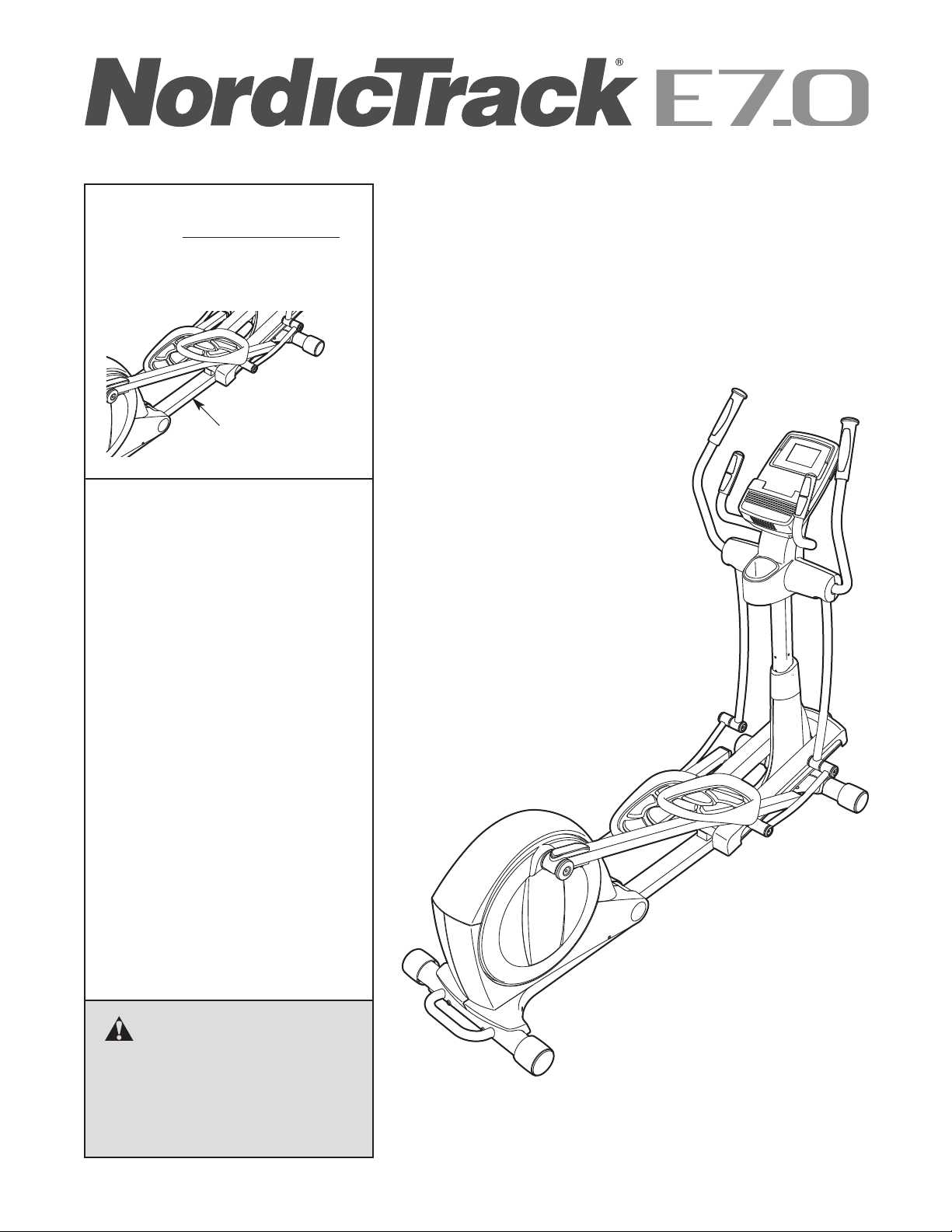
Serial Number
Decal (under frame)
USERʼS MANUAL
Model No. NTEVEL87910.1
Serial No.
Write the serial number in the space
above for reference.
www.iconeurope.com
QUESTIONS?
If you have questions, or if there are
missing parts, please contact us:
UK
Call: 08457 089 009
From Ireland: 053 92 36102
Website: www.iconsupport.eu
E-mail: [email protected]
Write:
ICON Health & Fitness, Ltd.
c/o HI Group PLC
Express Way
Whitwood, West Yorkshire
WF10 5QJ
UK
AUSTRALIA
Call: 1-800-237-173
E-mail:
This manual downloaded from http://www.manualowl.com
2
NordicTrack is a registered trademark of ICON IP, Inc.
TABLE OF CONTENTS
WARNING DECAL PLACEMENT . . . . . . . . . . . . . . . . . . . . . . . . . . . . . . . . . . . . . . . . . . . . . . . . . . . . . . . . . . . . . .2
I
MPORTANT PRECAUTIONS . . . . . . . . . . . . . . . . . . . . . . . . . . . . . . . . . . . . . . . . . . . . . . . . . . . . . . . . . . . . . . . .3
BEFORE YOU BEGIN . . . . . . . . . . . . . . . . . . . . . . . . . . . . . . . . . . . . . . . . . . . . . . . . . . . . . . . . . . . . . . . . . . . . . .4
ASSEMBLY . . . . . . . . . . . . . . . . . . . . . . . . . . . . . . . . . . . . . . . . . . . . . . . . . . . . . . . . . . . . . . . . . . . . . . . . . . . . . . .5
HOW TO USE THE ELLIPTICAL . . . . . . . . . . . . . . . . . . . . . . . . . . . . . . . . . . . . . . . . . . . . . . . . . . . . . . . . . . . . .14
MAINTENANCE AND TROUBLESHOOTING . . . . . . . . . . . . . . . . . . . . . . . . . . . . . . . . . . . . . . . . . . . . . . . . . . .22
EXERCISE GUIDELINES . . . . . . . . . . . . . . . . . . . . . . . . . . . . . . . . . . . . . . . . . . . . . . . . . . . . . . . . . . . . . . . . . . .24
PART LIST . . . . . . . . . . . . . . . . . . . . . . . . . . . . . . . . . . . . . . . . . . . . . . . . . . . . . . . . . . . . . . . . . . . . . . . . . . . . . .27
EXPLODED DRAWING . . . . . . . . . . . . . . . . . . . . . . . . . . . . . . . . . . . . . . . . . . . . . . . . . . . . . . . . . . . . . . . . . . . .29
ORDERING REPLACEMENT PARTS . . . . . . . . . . . . . . . . . . . . . . . . . . . . . . . . . . . . . . . . . . . . . . . . . .Back Cover
RECYCLING INFORMATION . . . . . . . . . . . . . . . . . . . . . . . . . . . . . . . . . . . . . . . . . . . . . . . . . . . . . . . . .Back Cover
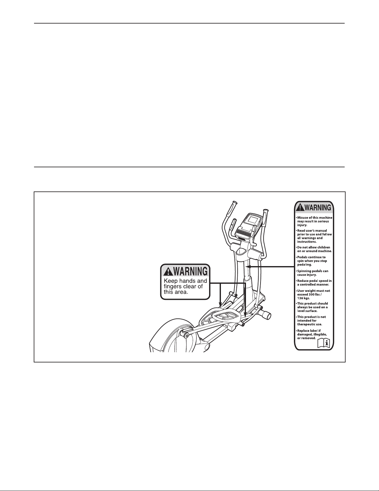
WARNING DECAL PLACEMENT
This drawing shows the location(s) of the warning
decal(s). If a decal is missing or illegible, see the
front cover of this manual and request a free
replacement decal. Apply the decal in the loca-
tion shown. Note: The decal(s) may not be shown
at actual size.
This manual downloaded from http://www.manualowl.com

3
WARNING: To reduce the risk of serious injury, read all important precautions and
instructions in this manual and all warnings on your elliptical before using your elliptical. ICON
assumes no responsibility for personal injury or property damage sustained by or through the use of
t
his product.
IMPORTANT PRECAUTIONS
1. Before beginning any exercise program,
consult your physician. This is especially
important for persons over age 35 or
persons with pre-existing health problems.
2. Use the elliptical only as described in this
manual.
3. It is the responsibility of the owner to ensure
that all users of the elliptical are adequately
informed of all precautions.
4. The elliptical is intended for home use only.
Do not use the elliptical in a commercial,
rental, or institutional setting.
5. Keep the elliptical indoors, away from
moisture and dust. Do not put the elliptical in
a garage or covered patio, or near water.
6. Place the elliptical on a level surface, with a
mat beneath it to protect the floor or carpet.
Make sure that there is at least 3 ft. (0.9 m) of
clearance in the front and rear of the elliptical
and 2 ft. (0.6 m) on each side.
7. Inspect and properly tighten all parts
regularly. Replace any worn parts
immediately.
8. Keep children under age 12 and pets away
from the elliptical at all times.
9. The elliptical should not be used by persons
weighing more than 300 lbs. (136 kg).
10. Wear appropriate clothes while exercising;
do not wear loose clothes that could become
caught on the elliptical. Always wear athletic
shoes for foot protection while exercising.
11. Hold the handlebars or the upper body arms
when mounting, dismounting, or using the
elliptical.
12. The pulse sensor is not a medical device.
Various factors may affect the accuracy of
heart rate readings. The pulse sensor is
intended only as an exercise aid in
determining heart rate trends in general.
13. The elliptical does not have a freewheel; the
pedals will continue to move until the
flywheel stops. Reduce your pedaling speed
in a controlled way.
14. Keep your back straight while using the
elliptical; do not arch your back.
15. Over exercising may result in serious injury
or death. If you feel faint or if you experience
pain while exercising, stop immediately and
cool down.
This manual downloaded from http://www.manualowl.com
4
BEFORE YOU BEGIN
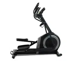
Thank you for selecting the revolutionary NordicTrack
®
E
7.0 elliptical. The E 7.0 elliptical provides an impres-
sive selection of features designed to make your
workouts at home more effective and enjoyable.
For your benefit, read this manual carefully before
you use the elliptical. If you have questions after
reading this manual, please see the front cover of this
manual. To help us assist you, note the product model
n
umber and serial number before contacting us. The
model number and the location of the serial number
decal are shown on the front cover of this manual.
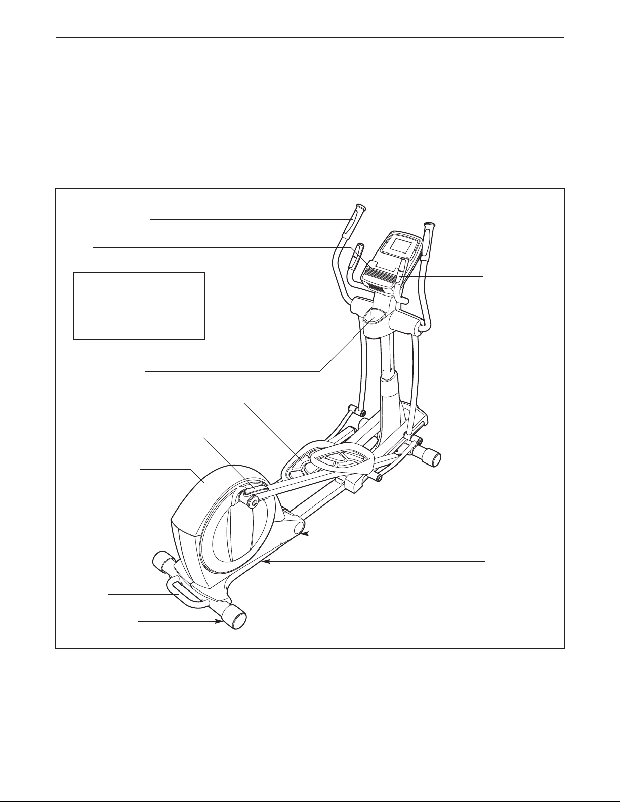
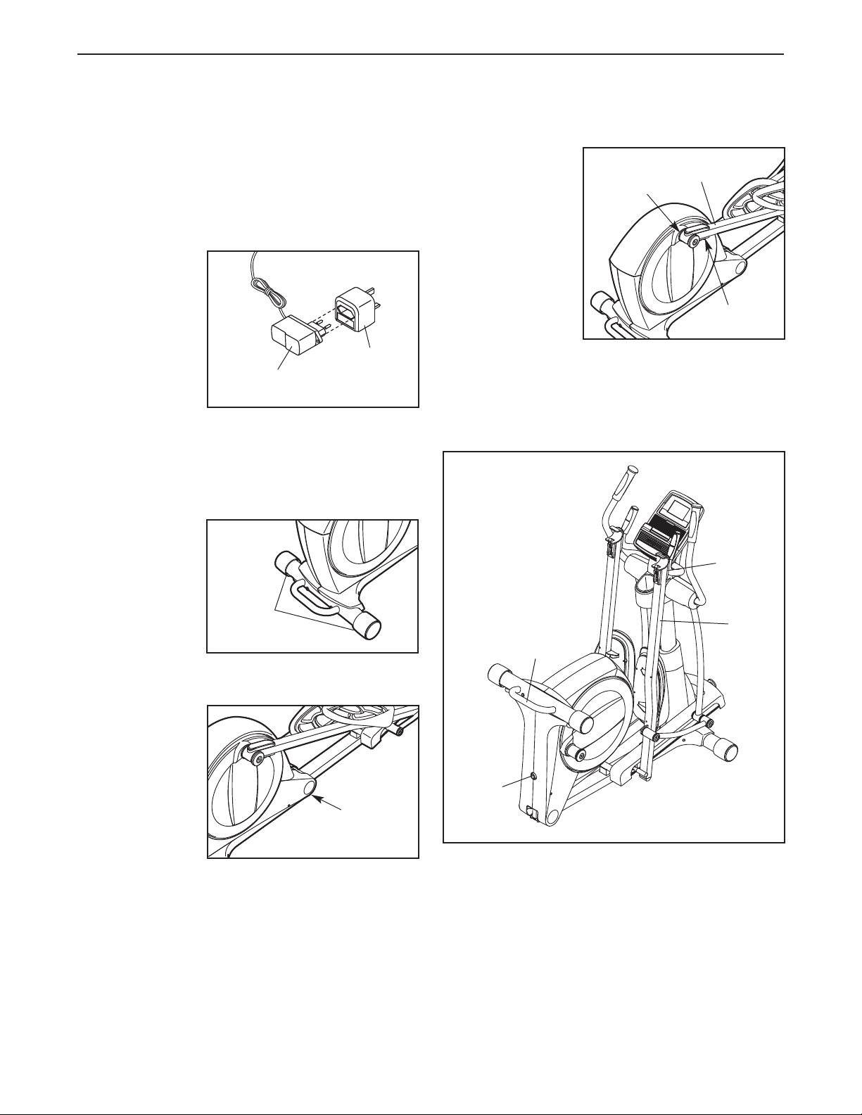
Before reading further, please familiarize yourself with
the parts that are labeled in the drawing below.
Pulse Sensor
Upper Body Arm
Access Cover
Wheel
Pedal
Accessory Tray
Console
Leveling Foot
Handle
Latch Button
Ramp
Storage Magnet
Fan
Pedal Arm Latch
Leveling Foot
H: 5 ft. 2 in. (157 cm)
W: 2 ft. (61 cm)
L: 6 ft. (183 cm)
Wt.: 176 lbs. (80 kg)
This manual downloaded from http://www.manualowl.com
5
ASSEMBLY
Assembly requires two persons. Place all parts of the elliptical in a cleared area and remove the packing
materials. Do not dispose of the packing materials until assembly is completed.
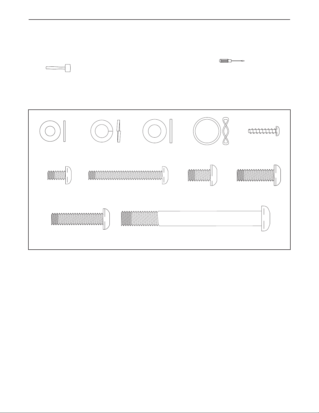
In addition to the included tool(s), assembly requires a Phillips screwdriver and a rubber
mallet .
See the drawings below to identify the small parts needed for assembly. The number in parentheses below each
drawing is the key number of the part, from the PART LIST near the end of this manual. The number following
the key number is the quantity needed for assembly. Note: If a part is not in the hardware kit, check to see if
it has been preassembled. To avoid damaging parts, do not use power tools for assembly.
M10 x 95mm Patch
Screw (100)–4
M8 Split Washer
(103)–14
M6 x 12mm Patch
Screw (111)–4
M8 Washer
(95)–6
M8 x 16mm Patch
Screw (102)–16
Wave Washer
(118)–2
M6 Washer
(112)–8
M8 x 25mm Patch
Screw (121)–2
M6 x 50mm Patch
Screw (62)–4
M8 x 35mm Patch
Screw (137)–2
M4 x 19mm
Screw (123)–8
This manual downloaded from http://www.manualowl.com
6
1.
O
rient the Rear Stabilizer (4) as shown.
Attach the Rear Stabilizer (4) to the Folding
Frame (2) with two M10 x 95mm Patch Screws
(100).
Next, hold the handle on the Rear Stabilizer (4),
press the Latch Button (67), and lower the Rear
Stabilizer and the Folding Frame (2) to the floor.
4
1
To make assembly easier, read the
i
nformation on page 5 before you begin.
100
Handle
2
67
2. Orient the Front Stabilizer (3) so that the welded
tubes are facing away from the Main Frame (1).
While a second person lifts the front of the Main
Frame (1), attach the Front Stabilizer (3) with
two M10 x 95mm Patch Screws (100).
2
3
1
100
Welded
Tubes
This manual downloaded from http://www.manualowl.com
7
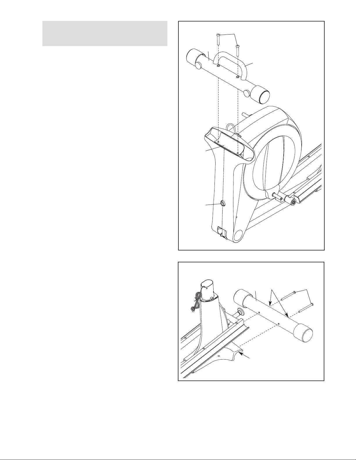
3. Identify and orient the Upright (5) and the Top
Cover (27) as shown.
Slide the Top Cover (27) upward onto the
Upright (5).
Then, have a second person hold the Upright
(5) and the Top Cover (27) near the Main Frame
(1) until step 4.
Locate the wire tie in the Upright (5). Tie the
lower end of the wire tie to the Main Wire (60).
Next, pull the upper end of the wire tie until the
Main Wire is routed completely through the
Upright.
Tip: To prevent the Main Wire (60) from
falling into the Upright (5), secure the Main
Wire with the wire tie.
3
5
Wire Tie
Wire Tie
27
60
1
4
4. Tip: Avoid pinching the Main Wire (60). Insert
the Upright (5) into the Main Frame (1).
Attach the Upright (5) with four M8 x 16mm
Patch Screws (102) and four M8 Split Washers
(103); do not tighten the Patch Screws yet.
You will tighten the Patch Screws at the end
of step 11.
5
102
102
102
102
103
103
103
103
1
Avoid pinching the
Main Wire (60)
This manual downloaded from http://www.manualowl.com
8
5
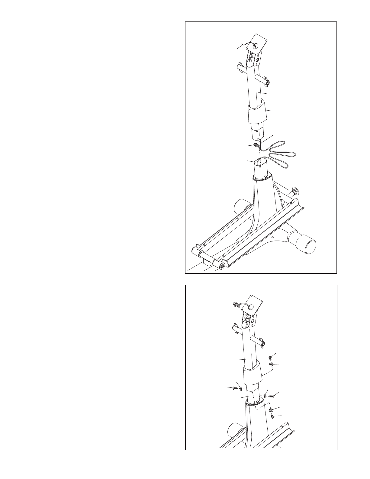
5. Using a small plastic bag to keep your fingers
clean, apply a coat of the included grease to the
U
pright Axle (48) and to two Wave Washers
(118).
Tip: Avoid damaging the Main Wire (60).
Insert the Upright Axle (48) through the Upright
(5) and center it. Slide a Wave Washer (118)
onto each side of the Upright Axle.
Next, identify the Right and Left Upper Body
Legs (6, 7), which are marked with “Right” and
“Left” stickers, and orient them as shown.
Slide the Right and Left Upper Body Legs (6, 7)
onto the right and left sides of the Upright Axle
(48).
Tighten an M8 x 16mm Patch Screw (102) and
an M8 Washer (95) into each end of the Upright
Axle (48) at the same time.
Avoid damaging the
Main Wire (60)
Grease
Grease
95
5
7
102
95
102
118
48
60
6
118
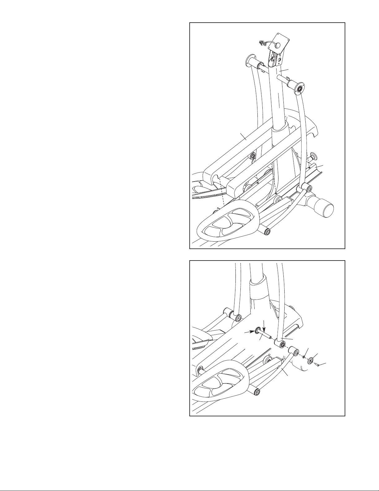
6. Identify the Right Pedal (14), the Right Pedal
Pad (104), and the Right Pedal Arm (12)
assembly, which are marked with “Right” stick-
ers, and orient them as shown.
Set the Right Pedal Pad (104) on the Right
Pedal Arm (12). Then, set the Right Pedal (14)
on the Right Pedal Pad.
Attach the Right Pedal (14) to the Right Pedal
Arm (12) with two M6 x 12mm Patch Screws
(111) and two M6 Washers (112); do not
tighten the Patch Screws yet.
Next, tighten two M6 x 50mm Patch Screws
(62) and two M6 Washers (112) into the Right
Pedal Arm (12) and the Right Pedal (14). Then,
tighten the two M6 x 12mm Patch Screws
(111).
Attach the Left Pedal (not shown) to the Left
Pedal Arm (not shown) assembly in the
same way.
6
14
12
111
112
112
62
104
This manual downloaded from http://www.manualowl.com
9
8a
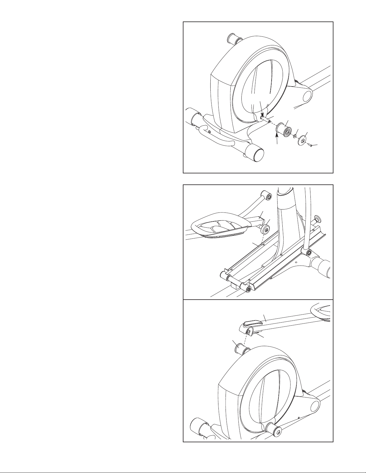
8. See drawing 8a. Locate the Pedal Arm Roller
(32) on the Left Pedal Arm (13).
Set the Pedal Arm Roller (32) on the left side of
the Ramp (130).
See drawing 8b. Pull upward on the Latch (50)
on the Left Pedal Arm (13).
Press the Left Pedal Arm (13) onto the left
Pedal Arm Sleeve (46). Make sure that the
Left Pedal Arm latches into place.
Repeat this step on the other side of the
elliptical.
32
13
130
7. Apply grease to the axle on the right Crank Arm
(39).
O
rient a Pedal Arm Sleeve (46) so that the flat
side is facing the elliptical. Slide the Pedal Arm
S
leeve onto the axle on the right Crank Arm
(39).
Attach the Pedal Arm Sleeve (46) with an M8 x
25mm Patch Screw (121), a Large Axle Cover
(113), and an M8 Washer (95). Tip: Avoid
damaging the Large Axle Cover when tight-
ening the Patch Screw.
Repeat this step on the other side of the
elliptical.
8b
46
13
50
7
95
113
Flat
Side
121
39
Grease
46
This manual downloaded from http://www.manualowl.com
10
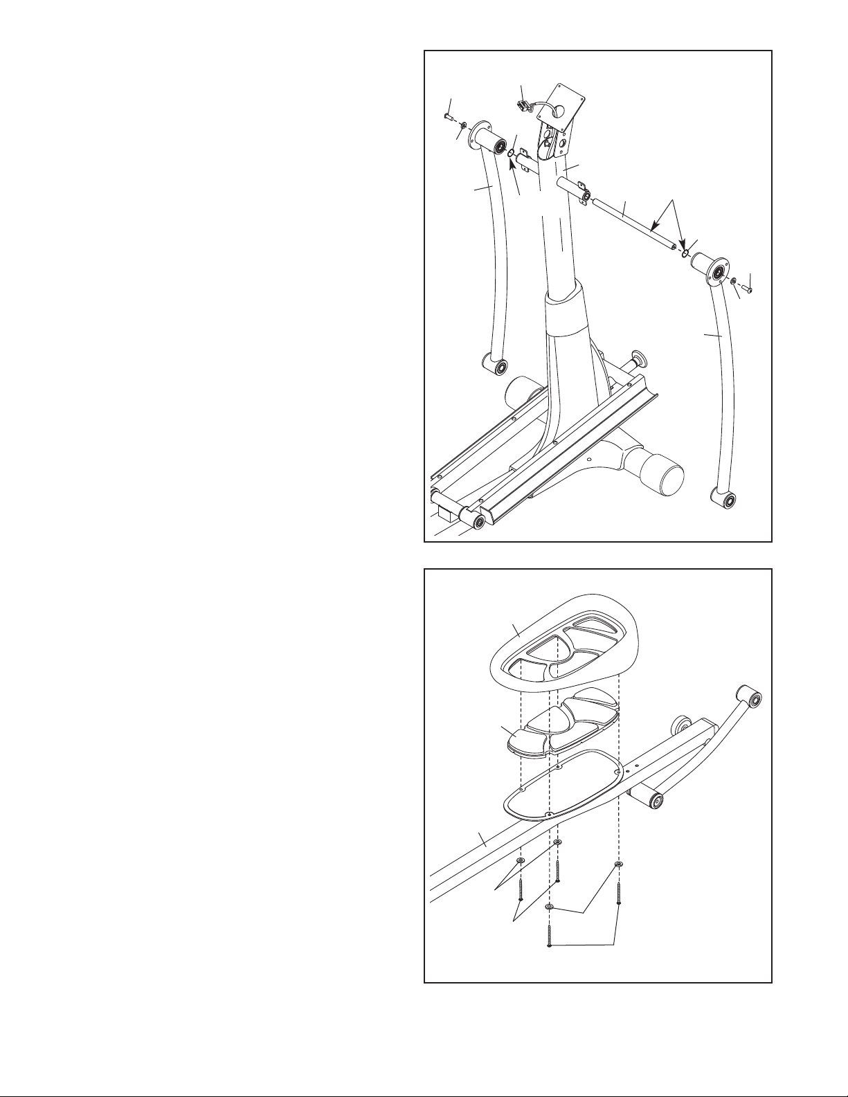
10. Apply grease to a Link Arm Axle (114).
Insert the Link Arm Axle (114) into the Right
Upper Body Leg (6) and the Right Link Arm (43)
from the side shown.
Insert a hex key into the M8 x 35mm Patch
Screw (137) in the Link Arm Axle (114).
Using a second hex key, tighten another M8 x
35mm Patch Screw (137), a Small Axle Cover
(56), and an M8 Washer (95) into the other end
of the Link Arm Axle (114). Tip: Avoid damag-
ing the Small Axle Cover when tightening
the Patch Screw.
Repeat this step on the other side of the
elliptical.
10
9. Orient the Ramp Cover (131) around the
Upright (5) as shown.
P
ress the tabs on the Ramp Cover (131) into
the Ramp (130).
9
131
130
5
95
43
56
6
114
137
137
Grease
This manual downloaded from http://www.manualowl.com
11
12
11
9
7
6
8
102
102
103
1
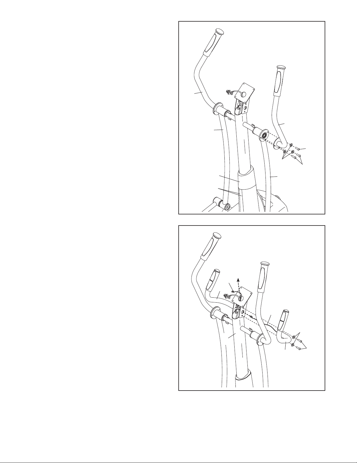
1. Identify the Right Upper Body Arm (8), which is
marked with a “Right” sticker, and orient it as
s
hown.
Have a second person hold the Right Upper
Body Arm (8) near the Right Upper Body Leg
(
6).
Attach the Right Upper Body Arm (8) to the
Right Upper Body Leg (6) with three M8 x
16mm Patch Screws (102) and three M8 Split
Washers (103).
Attach the Left Upper Body Arm (9) to the
Left Upper Body Leg (7) in the same way.
See step 4 on page 7. Tighten the M8 x
16mm Patch Screws (102).
Slide the Top Cover (27) downward and press it
into the Right and Left Frame Covers (21, 22).
12. Identify the Right Handlebar (10), which is
marked with a “Right” sticker, and orient it as
shown.
Have a second person hold the Right
Handlebar (10) near the right side of the Upright
(5).
Insert the Pulse Wire (105) from the Right
Handlebar (10) into the right side of the Upright
(5) and pull it upward out of the top of the
Upright.
Tip: Avoid pinching the Pulse Wire (105).
Attach the Right Handlebar (10) to the Upright
(5) with two M8 x 16mm Patch Screws (102)
and two M8 Split Washers (103).
Attach the Left Handlebar (11) in the same
way.
102
103
105
105
10
11
5
Avoid pinching the
Pulse Wires (105)
27
21, 22
This manual downloaded from http://www.manualowl.com
12
13
14
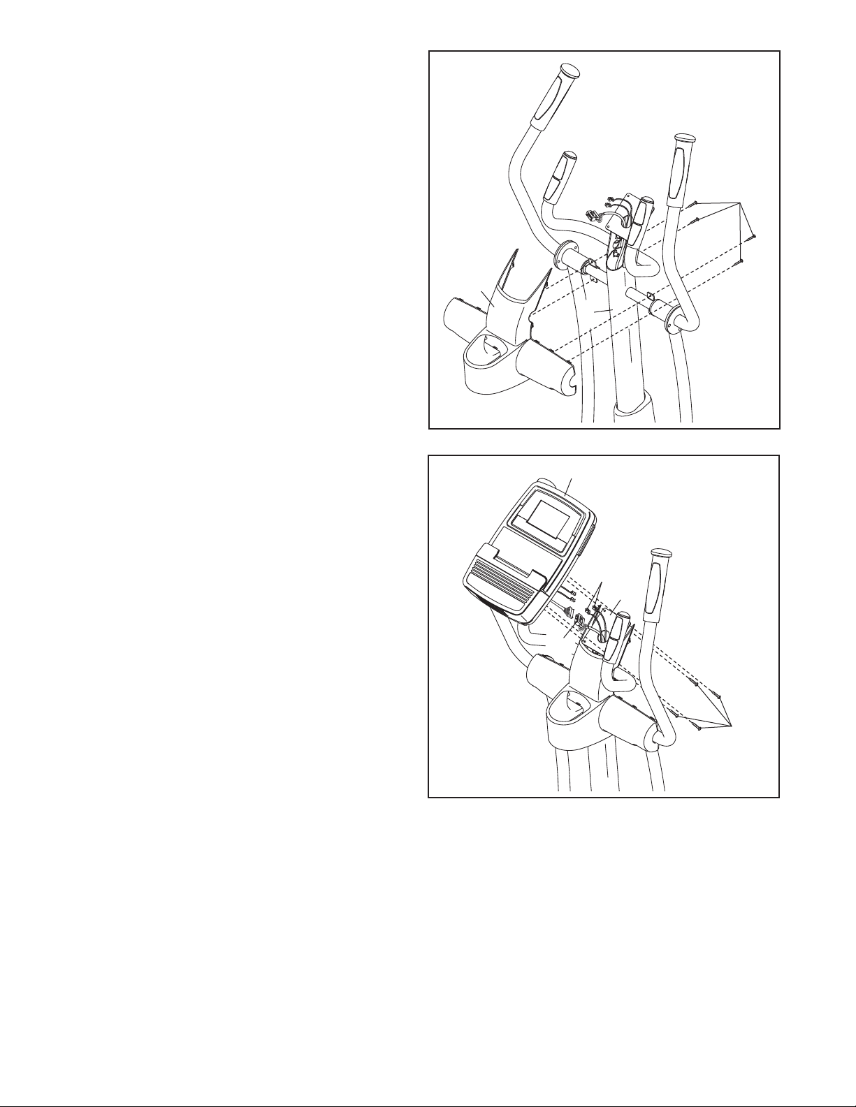
14. Untie and discard the wire tie attached to the
Main Wire (60).
While a second person holds the Console (33)
near the Upright (5), connect the wires on the
Console to the Main Wire (60) and to the Pulse
Wires (105).
Insert the excess wire downward into the
Upright (5) or upward into the Console (33).
Tip: Avoid pinching the wires. Attach the
Console (33) to the Upright (5) with four M4 x
19mm Screws (123).
105
5
60
25
123
5
13. Orient the Rear Upright Cover (25) as shown.
Attach the Rear Upright Cover (25) to the
Upright (5) with four M4 x 19mm Screws (123).
Avoid pinching
the wires
33
123
This manual downloaded from http://www.manualowl.com
13
17. Make sure that all parts of the elliptical are properly tightened. Note: Some hardware may be left over
after assembly is completed. To protect the floor or carpet from damage, place a mat under the elliptical.
24
25
1
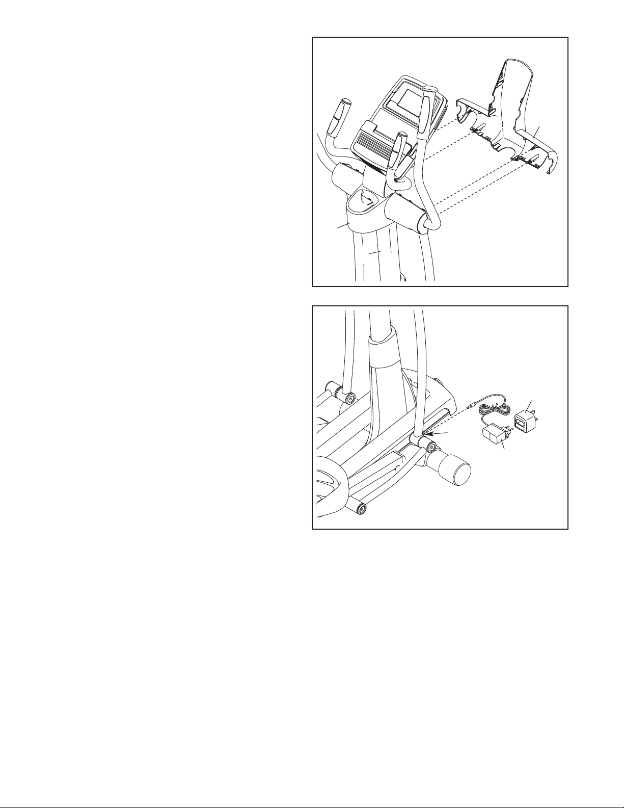
5. Orient the Front Upright Cover (24) as shown.
Attach the Front Upright Cover (24) around the
Upright (5) by pressing the tabs on the Front
U
pright Cover into the Rear Upright Cover (25).
5
15
139
138
16. Plug the Power Adapter (138) into the Power
Receptacle (135).
If necessary, plug the Power Adapter (138) into
the Plug Adapter (139).
To plug the Power Adapter (138) into an outlet,
see HOW TO PLUG IN THE POWER
ADAPTER on page 14.
135
16
This manual downloaded from http://www.manualowl.com
14
HOW TO USE THE ELLIPTICAL
HOW TO PLUG IN THE POWER ADAPTER
IMPORTANT: If the elliptical has been exposed to
c
old temperatures, allow it to warm to room tem-
perature before plugging in the power adapter. If
you do not do this, you may damage the console
displays or other electronic components.
Plug the power
adapter into the
receptacle on
the frame of the
elliptical. Next,
plug the power
adapter into the
plug adapter.
Then, plug the
plug adapter into
an appropriate
outlet that is properly installed in accordance with all
local codes and ordinances.
HOW TO LEVEL THE ELLIPTICAL
If the elliptical
rocks slightly on
your floor during
use, turn one or
both of the level-
ing feet beneath
the rear stabi-
lizer until the
rocking motion is
eliminated.
If the frame of
the elliptical
flexes during
use, turn the
center leveling
foot until the flex-
ing motion is
eliminated.
HOW TO FOLD AND UNFOLD THE ELLIPTICAL
When the elliptical
i
s not in use, the
frame can be
folded out of the
way. First, lift the
latch under each
pedal arm, and lift
the pedal arms off
the sleeves on the
crank arms.
Next, raise the pedal arms until the magnets on the
pedal arms touch the handlebars; the magnets will
hold the pedal arms in place. Then, hold the handle
and lift the frame until it locks in a vertical position.
To use the elliptical, first hold the handle, press the
latch button, and lower the frame.
Next, pull the magnets on the pedal arms off the han-
dlebars. Then, lift the latches under the pedal arms,
and set the pedal arms on the sleeves on the crank
arms. Release the latches, and make sure that the
pedal arms are securely connected to the crank arms.
Latch
Sleeve
P
edal Arm
Handle
Latch
Button
Pedal
Arm
Magnet
Leveling
Feet
Leveling
Foot
Power Adapter
Plug
Adapter
This manual downloaded from http://www.manualowl.com
15
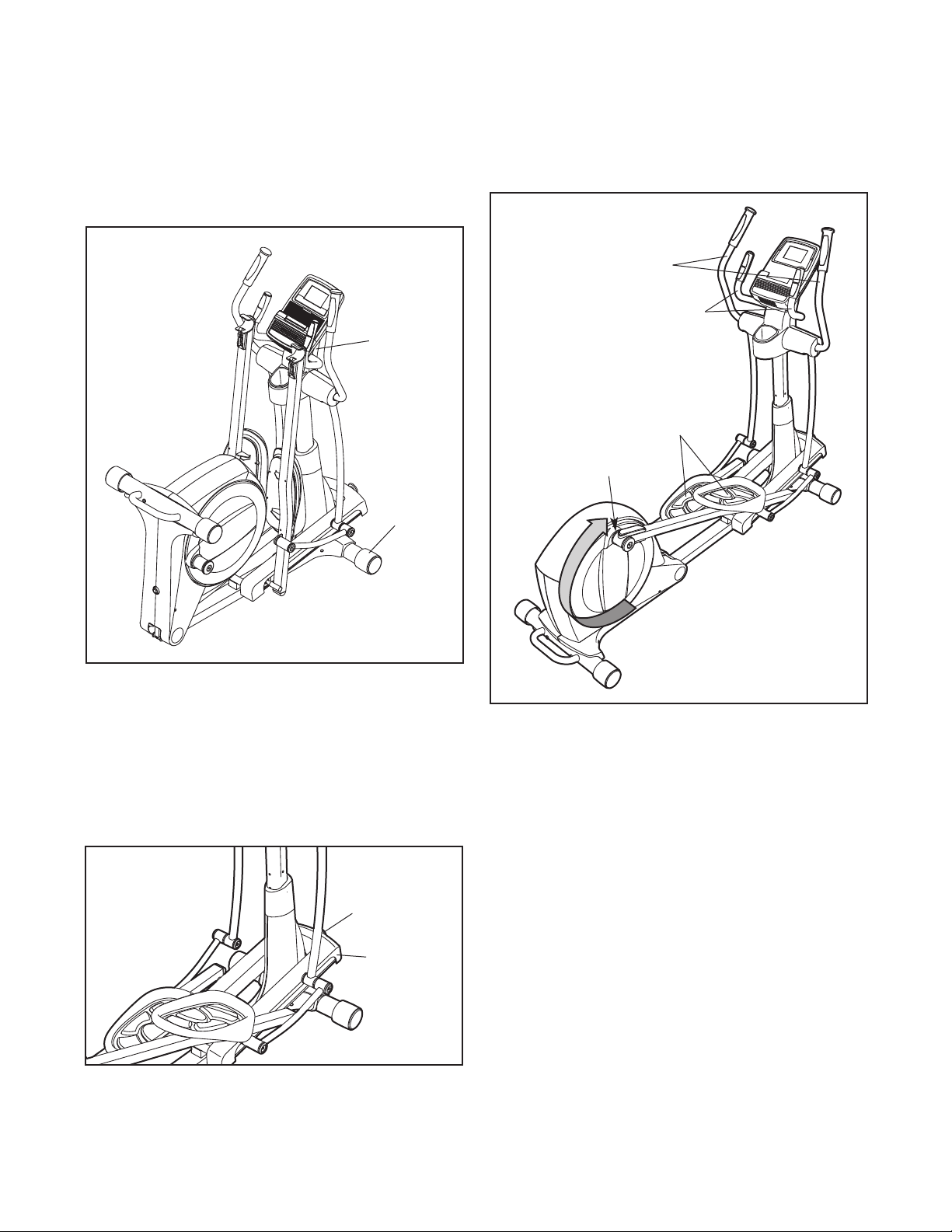
HOW TO MOVE THE ELLIPTICAL
To move the elliptical, first fold it as described above.
N
ext, stand in front of the elliptical, hold the upright,
and place one foot against one of the wheels. Pull the
u
pright until the elliptical rolls on the wheels. With the
help of a second person, carefully move the elliptical
to the desired location, and then lower it to the floor.
HOW TO CHANGE THE INCLINE OF THE RAMP
To vary the motion of the pedals, you can change the
incline of the ramp. To change the incline, pull the
ramp knob outward, raise or lower the ramp, and
engage the ramp pin into one of the adjustment holes
in the front of the frame.
HOW TO EXERCISE ON THE ELLIPTICAL
To mount the elliptical, hold the upper body arms and
s
tep onto the pedal that is in the lowest position. Next,
step onto the other pedal. Push the pedals until they
b
egin to move with a continuous motion.
Note: The crank arms can turn in either direction.
It is recommended that you turn the crank arms in
the direction shown by the arrow; however, for
variety you can turn the crank arms in the oppo-
site direction.
To dismount the elliptical, wait until the pedals come to
a complete stop. Note: The elliptical does not have
a free wheel; the pedals will continue to move until
the flywheel stops. When the pedals are stationary,
step off the higher pedal first. Then, step off the lower
pedal.
Upper Body Arms
Handlebars
Pedals
Crank Arm
Pull on
the upright
Place
your foot
here
Ramp
Knob
Ramp
This manual downloaded from http://www.manualowl.com
16
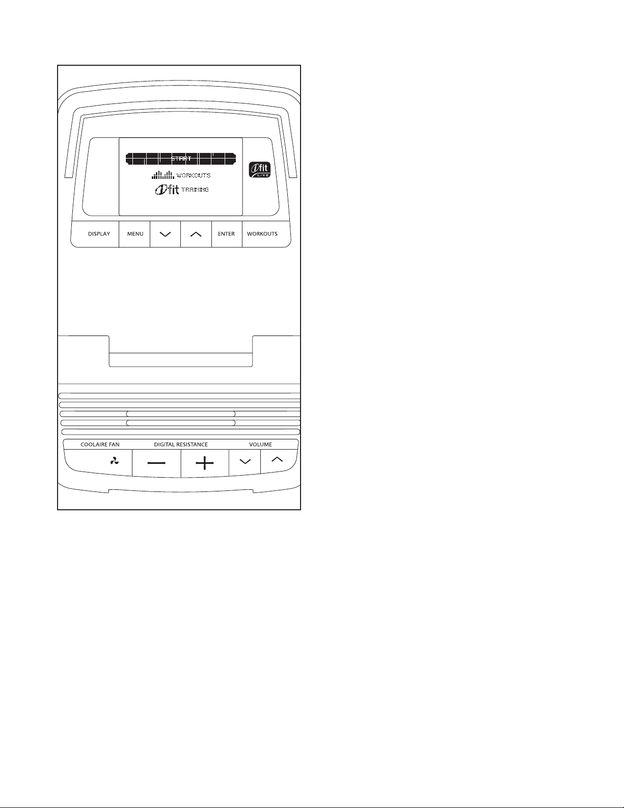
CONSOLE DIAGRAM FEATURES OF THE CONSOLE
The advanced console offers an array of features
d
esigned to make your workouts more effective and
enjoyable.
When you use the manual mode of the console, you
can change the resistance of the pedals with the touch
of a button. While you exercise, the console will dis-
play continuous exercise feedback. You can also
measure your heart rate using the handgrip pulse sen-
sor or the optional chest pulse sensor.
The console also offers eighteen preset workouts—ten
weight loss workouts and eight timed workouts. Each
workout automatically changes the resistance of the
pedals and prompts you to vary your pedaling pace as
it guides you through an effective workout.
The console also features an iFit training mode that
allows you to connect to your wireless network
through an iFit Live module. The optional iFit Live
module allows you to download personalized workouts
and to track and analyze workout information on the
iFit Live website. To purchase an iFit Live module at
any time, go to www.iFit.com or call the telephone
number on the front cover of this manual.
You can even connect your MP3 player or CD player
to the console sound system and listen to your favorite
music or audio books while you exercise.
To activate the console, see page 17. To use the
manual mode, see page 17. To use a preset work-
out, see page 18. To use the iFit training mode, see
page 20. To use the sound system, see page 20. To
use the information mode, see page 20.
Note: If there is a sheet of plastic on the display,
remove the plastic.
This manual downloaded from http://www.manualowl.com

17
HOW TO ACTIVATE THE CONSOLE
The included power adapter must be used to operate
the elliptical. See HOW TO PLUG IN THE POWER
ADAPTER on page 14. When the power adapter is
p
lugged in, the displays will light and the console will
be ready for use.
HOW TO TURN OFF THE CONSOLE
If the pedals do not move for several seconds, a tone
will sound and the console will pause.
If the pedals do not move for several minutes and the
buttons are not pressed, the console will turn off and
the display will be reset.
When you are finished exercising, unplug the power
adapter. IMPORTANT: If you do not do this, the
electrical components on the elliptical may wear
prematurely.
HOW TO USE THE MANUAL MODE
1. Begin pedaling or press any button on the
console to turn on the console.
See HOW TO ACTIVATE THE CONSOLE above.
2. Select the manual mode.
Each time you turn on the console, the main menu
will appear.
To select the manual
mode, press the
increase and decrease
buttons next to the Enter
button and highlight
START. Then, press the
Enter button.
If you have selected a workout or the iFit Training
mode, press the Menu button to return to the main
menu.
3. Change the resistance of the pedals as
desired.
As you pedal, change the resistance of the pedals
by pressing the Digital Resistance increase and
d
ecrease buttons.
Note: After you press the buttons, it will take a
moment for the pedals to reach the selected resis-
tance level.
4.
Follow your progress with the display.
The console offers several display modes. The
display mode that you select will determine which
workout information is shown. Press the Display
button repeatedly to select the desired display
mode.
The display can show the following workout
information:
Calories—This display mode will show the
approximate number of calories you have burned.
Profile—When a workout is selected, this display
mode will show a profile of the resistance levels
for the workout.
Pulse—This display mode will show your heart
rate when you use the handgrip pulse sensor or
the optional chest pulse sensor (see step 5 on
page 18).
Resistance—This display mode will show the
resistance level of the pedals for a few seconds
each time the resistance level changes.
RPM—This display mode will show your pedaling
pace, in revolutions per minute (rpm).
Strides—This display mode will show the total
number of strides you have pedaled.
Time—When the manual mode is selected, this
display mode will show the elapsed time. When a
workout is selected, the display mode will show
the time remaining in the workout instead of the
elapsed time.
Change the volume level of the console by press-
ing the Volume increase and decrease buttons.
This manual downloaded from http://www.manualowl.com
18
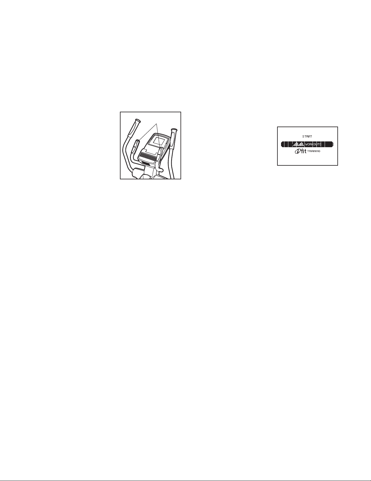
5. Measure your heart rate if desired.
You can measure you heart rate using either the
handgrip pulse sensor or the optional chest pulse
sensor (see page 21 for information about the
optional chest pulse sensor).
N
ote: If you hold the handgrip pulse sensor
and wear the chest pulse sensor at the same
time, the console will not display your heart
rate accurately.
If there are sheets of
plastic on the metal
contacts on the hand-
grip pulse sensor,
remove the plastic. To
measure your heart
rate, hold the handgrip
pulse sensor with your
palms resting against
the metal contacts.
Avoid moving your
hands or gripping the contacts tightly.
When your pulse is detected, your heart rate will
appear in the display. For the most accurate heart
rate reading, hold the contacts for at least 15
seconds.
If the display does not show your heart rate, make
sure that your hands are positioned as described.
Be careful not to move your hands excessively or
squeeze the metal contacts tightly. For optimal
performance, clean the metal contacts using a soft
cloth; never use alcohol, abrasives, or chemi-
cals to clean the contacts.
6. Turn on the fan if desired.
Press the Coolaire Fan button repeatedly to turn
on or to turn off the fan.
7. When you are finished using the elliptical, the
console will turn off automatically.
See HOW TO TURN OFF THE CONSOLE on
page 17.
HOW TO USE A PRESET WORKOUT
1. Begin pedaling or press any button on the
console to turn on the console.
See HOW TO ACTIVATE THE CONSOLE on page
17.
2. Select a preset workout.
If you have selected a workout or the iFit Training
mode, press the Menu button to return to the main
menu.
To select a preset work-
out, first press the
increase and decrease
buttons next to the Enter
button and highlight
WORKOUTS. Then,
press the Enter button.
Next, press the increase and decrease buttons to
highlight the desired workout category. Then,
press the Enter button.
You can also press the Workouts button repeat-
edly to select a workout category or the manual
mode.
Press the increase and decrease buttons to high-
light the desired workout subcategory. Then, press
the Enter button.
Press the increase and decrease buttons to high-
light the name of the desired workout. The
duration, the maximum rpm (pedaling pace), the
maximum resistance level, and a profile of the
resistance levels of the workout will appear in the
right side of the display. Then, press the Enter
button.
3. Begin pedaling to start the workout.
Each workout is divided into one-minute seg-
ments. One resistance level and one target rpm
(pedaling pace) are programmed for each seg-
ment. Note: The same resistance level and/or
target rpm may be programmed for consecutive
segments.
Contacts
This manual downloaded from http://www.manualowl.com

19
T
he workout profile will
show your progress.
T
he flashing segment of
the profile represents
the current segment of
the workout. The height
o
f the flashing segment
indicates the resistance level for the current
segment.
When the first segment of the workout ends, the
resistance level and the target rpm for the second
segment will appear in the display for a few sec-
onds to alert you. The next segment of the profile
will begin to flash, and the pedals will automati-
cally adjust to the resistance level for the next
segment.
As you exercise, you will be prompted to keep
your pedaling pace (rpm) near the target rpm for
the current segment. When the word FASTER
appears in the display, increase your pedaling
pace. When the word SLOWER appears,
decrease your pedaling pace. When no words
appear, maintain your current pedaling pace.
IMPORTANT: The target rpm is intended only to
provide motivation. Your actual pedaling pace
(rpm) may be slower than the target rpm. Make
sure to pedal at a pace that is comfortable for
you.
I
f the resistance level for the current segment is
too high or too low, you can manually override the
s
etting by pressing the Digital Resistance buttons.
IMPORTANT: When the current segment of the
workout ends, the pedals will automatically
adjust to the resistance level for the next
s
egment.
The workout will continue in this way until the last
segment ends. To stop the workout at any time,
stop pedaling. A tone will sound and the time will
begin to flash in the display. To restart the workout,
simply resume pedaling.
4. Follow your progress with the display.
See step 4 on page 17.
5.
Measure your heart rate if desired.
See step 5 on page 18.
6. Turn on the fan if desired.
See step 6 on page 18.
7. When you are finished using the elliptical, the
console will turn off automatically.
See HOW TO TURN OFF THE CONSOLE on
page 17.
Current Segment
This manual downloaded from http://www.manualowl.com

20
HOW TO USE THE IFIT TRAINING MODE
T
he optional iFit Live module allows your console to
communicate with your wireless network and unlocks
exciting new features. For example, you can download
personalized workouts, create your own workouts,
track your workout results, and access many other
features on the iFit Live website. To purchase an iFit
L
ive module at any time, go to www.iFit.com or
call the telephone number on the front cover of
this manual.
To select the iFit training mode, insert the iFit Live
module into the console. Press the Menu button and
then press the increase and decrease buttons next to
the Enter button and highlight IFIT TRAINING. Then,
press the Enter button.
For more information about the iFit training mode, go
to www.iFit.com. Note: To use the iFit Live module,
you must have access to a computer with an internet
connection and a USB port. You must also have your
own wireless network including an 802.11b router with
SSID broadcast enabled (hidden networks are not
supported). You will also need an iFit.com member-
ship.
HOW TO USE THE SOUND SYSTEM
To play music or audio books through the console
sound system while you exercise, plug the included
audio cable into the jack on the side of the console
and into a jack on your MP3 player or CD player;
make sure that the audio cable is fully plugged in.
Next, press the play button on your MP3 player or CD
player. Adjust the volume level using the volume con-
trol on your MP3 player or CD player or press the
Volume increase and decrease buttons on the console
(see the drawing on page 16).
HOW TO USE THE INFORMATION MODE
T
he console features an information mode that allows
you to view usage information, select a unit of mea-
surement for the iFit Live workouts, and to adjust the
contrast level of the displays.
When an iFit Live module is connected to the console,
y
ou can also use the information mode to choose an
audio setting for the voice of the personal trainer,
check the status of the iFit Live module, and check for
downloads.
1. Select the information mode.
To select the information
mode, press and hold
down the Display button
for a few seconds until
the information mode
appears in the display.
2. View usage information.
The display will show the total distance that has
been pedaled on the elliptical. The display will also
show the total number of hours that the elliptical
has been used.
3. Select a unit of measurement if desired.
Note: Some iFit Live workouts will display the dis-
tance in miles or kilometers.
The word ENGLISH for English miles or the word
METRIC for metric kilometers will appear in the
display to indicate the currently selected unit of
measurement.
To change the unit of measurement, press the
increase and decrease buttons until the bullet
appears next to the word UNITS. Then, press the
Enter button repeatedly to select the desired unit
of measurement.
This manual downloaded from http://www.manualowl.com
21
4. Adjust the contrast level of the display if
desired.
The currently selected contrast level will also
a
ppear in the display. To change the contrast level,
press the increase and decrease buttons until the
bullet appears next to the word CONTRAST.
Press the Enter button and then press the
increase and decrease buttons repeatedly to
select the desired contrast level. Press the Enter
button again to save your selection.
5. Determine if an iFit Live module is connected
to the console.
If an iFit Live module is connected to the console,
the display will show the words WIFI STATUS or
USB STATUS.
If no accessory is connected, the display will show
the words NO MODULE DETECTED. If no acces-
sory is connected, go to step 9.
6. Select an audio setting for the voice of the
personal trainer if desired.
The currently selected audio setting for the voice
of the personal trainer will also appear in the
display.
To change the audio setting, press the increase
and decrease buttons until the bullet appears next
to the words TRAINER VOICE. Then, press the
Enter button repeatedly to turn the voice of the
personal trainer ON or OFF.
7. Check the status of the iFit Live module if
desired.
To check the status of the iFit Live module, press
t
he increase and decrease buttons until the bullet
appears next to the words CHECK WIFI STATUS
or CHECK USB STATUS.
Then, press the Enter button. After a few seconds,
the status of the iFit Live module will appear in the
display. To exit this display, press and hold down
the Display button for a few seconds.
8. Check for downloads if desired.
To check for iFit Live workouts and firmware down-
loads, press the increase and decrease buttons
until the bullet appears next to the words CHECK
FOR DOWNLOADS.
Then, press the Enter button. The console will
then check for iFit Live workouts and firmware
downloads.
9. Exit the information mode.
Press the Display button to exit the information
mode.
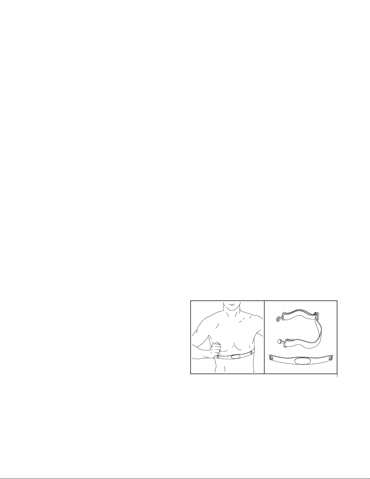
THE OPTIONAL CHEST PULSE SENSOR
The optional chest pulse sensor provides hands-free
operation and continuously monitors your heart rate
during your workouts. To purchase the optional
chest pulse sensor, see the front cover of this
manual.
This manual downloaded from http://www.manualowl.com
22
Inspect and tighten all parts of the elliptical regularly.
R
eplace any worn parts immediately.
To clean the elliptical, use a damp cloth and a small
amount of mild soap. IMPORTANT: To avoid damage
t
o the console, keep liquids away from the con-
sole and keep the console out of direct sunlight.
CONSOLE TROUBLESHOOTING
If the console does not turn on, make sure that the
power adapter is fully plugged in. If lines appear in the
console display, see HOW TO USE THE INFORMA-
TION MODE on page 20 and adjust the contrast level
of the display.
If the handgrip pulse sensor does not function prop-
erly, see step 5 on page 18.
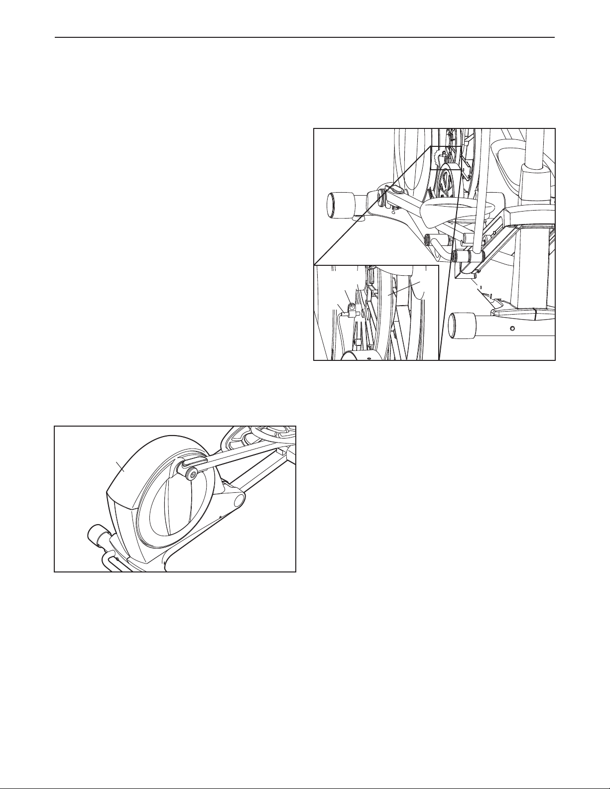
HOW TO ADJUST THE REED SWITCH
If the console does not display correct feedback, the
reed switch should be adjusted.
To adjust the reed switch, first unplug the power
adapter. Using a flat screwdriver, release the tabs on
the Access Cover (20) and pry the Access Cover
upward off the elliptical.
Next, look into the access opening and locate the
R
eed Switch (69). Rotate the Large Pulley (74) until a
Pulley Magnet (75) is aligned with the Reed Switch.
Next, loosen, but do not remove, the indicated M4 x
16mm Screw (106). Slide the Reed Switch (69)
slightly toward or away from the Pulley Magnet (75).
Then, retighten the M4 x 16mm Screw.
Plug in the power adapter and rotate the large pulley
for a moment. Repeat these actions until the console
displays correct feedback. When the reed switch is
correctly adjusted, reattach the access cover.
MAINTENANCE AND TROUBLESHOOTING
20
106
75
69
74
This manual downloaded from http://www.manualowl.com
23
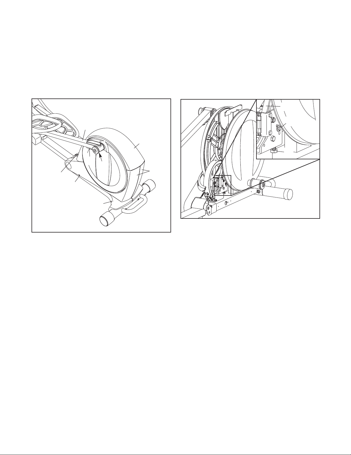
H
OW TO ADJUST THE DRIVE BELT
If you can feel the pedals slip while you are pedaling,
even when the resistance is adjusted to the highest
l
evel, the drive belt may need to be adjusted.
T
o adjust the drive belt, first unplug the power adapter.
Using a flat screwdriver, release the tabs on the
Access Cover (20) and pry the Access Cover upward
off the elliptical.
Next, lift the Latch (50) on the underside of the Left
Pedal Arm (13), and then lift the Left Pedal Arm off the
left Pedal Arm Sleeve (46).
T
hen, remove the M4 x 16mm Round Head Screws
(134) and the M4 x 42mm Screws (120) from the
Right and Left Shields (18, 19). (Note: Not all Screws
are shown. Be sure to note which size Screws come
f
rom which holes.) Then, carefully remove the Left
Shield.
Loosen the Pivot Screw (97). Tighten the Belt
Adjustment Screw (85) until the Drive Belt (38) is tight.
When the Drive Belt is tight, tighten the Pivot Screw.
When you are finished, reattach the left shield, replace
the left pedal arm, and reattach the access cover.
Then, plug in the power adapter.
13
19, 18
120
134
120
46
85
38
97
20
50
This manual downloaded from http://www.manualowl.com
24
These guidelines will help you to plan your exercise
program. For detailed exercise information, obtain a
reputable book or consult your physician. Remember,
proper nutrition and adequate rest are essential for
successful results.
EXERCISE INTENSITY
Whether your goal is to burn fat or to strengthen your
cardiovascular system, exercising at the proper inten-
sity is the key to achieving results. You can use your
heart rate as a guide to find the proper intensity level.
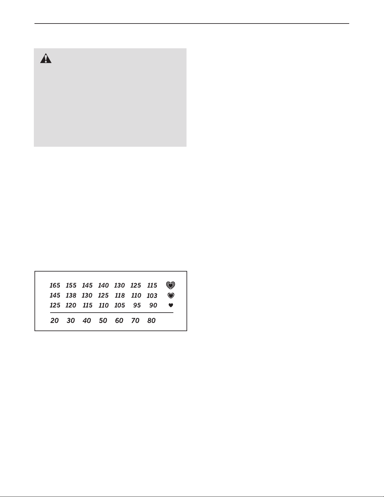
The chart below shows recommended heart rates for
fat burning and aerobic exercise.
To find the proper intensity level, find your age at the
bottom of the chart (ages are rounded off to the near-
est ten years). The three numbers listed above your
age define your “training zone.” The lowest number is
the heart rate for fat burning, the middle number is the
heart rate for maximum fat burning, and the highest
number is the heart rate for aerobic exercise.
Burning Fat—To burn fat effectively, you must exer-
cise at a low intensity level for a sustained period of
time. During the first few minutes of exercise, your
body uses carbohydrate calories for energy. Only after
the first few minutes of exercise does your body begin
to use stored fat calories for energy. If your goal is to
burn fat, adjust the intensity of your exercise until your
heart rate is near the lowest number in your training
zone. For maximum fat burning, exercise with your
heart rate near the middle number in your training
zone.
Aerobic Exercise—If your goal is to strengthen your
cardiovascular system, you must perform aerobic
exercise, which is activity that requires large amounts
of oxygen for prolonged periods of time. For aerobic
exercise, adjust the intensity of your exercise until
your heart rate is near the highest number in your
training zone.
WORKOUT GUIDELINES
Warming Up—Start with 5 to 10 minutes of stretching
and light exercise. A warm-up increases your body
temperature, heart rate, and circulation in preparation
for exercise.
Training Zone Exercise—Exercise for 20 to 30 min-
utes with your heart rate in your training zone. (During
the first few weeks of your exercise program, do not
keep your heart rate in your training zone for longer
than 20 minutes.) Breathe regularly and deeply as you
exercise–never hold your breath.
Cooling Down—Finish with 5 to 10 minutes of
stretching. Stretching increases the flexibility of your
muscles and helps to prevent post-exercise problems.
EXERCISE FREQUENCY
To maintain or improve your condition, complete three
workouts each week, with at least one day of rest
between workouts. After a few months of regular exer-
cise, you may complete up to five workouts each
week, if desired. Remember, the key to success is to
make exercise a regular and enjoyable part of your
everyday life.
EXERCISE GUIDELINES
WARNING: Before beginning this
or any exercise program, consult your physi-
c
ian. This is especially important for persons
over age 35 or persons with pre-existing
health problems.
The pulse sensor is not a medical device.
Various factors may affect the accuracy of
heart rate readings. The pulse sensor is
intended only as an exercise aid in determin-
ing heart rate trends in general.
This manual downloaded from http://www.manualowl.com

25
SUGGESTED STRETCHES
T
he correct form for several basic stretches is shown at the right. Move slowly as you stretch—never bounce.
1. Toe Touch Stretch
Stand with your knees bent slightly and slowly bend forward from
your hips. Allow your back and shoulders to relax as you reach
down toward your toes as far as possible. Hold for 15 counts,
then relax. Repeat 3 times. Stretches: Hamstrings, back of
knees, and back.
2. Hamstring Stretch
Sit with one leg extended. Bring the sole of the opposite foot
toward you and rest it against the inner thigh of your extended
leg. Reach toward your toes as far as possible. Hold for 15
counts, then relax. Repeat 3 times for each leg. Stretches:
Hamstrings, lower back, and groin.
3. Calf/Achilles Stretch
With one leg in front of the other, reach forward and place your
hands against a wall. Keep your back leg straight and your back
foot flat on the floor. Bend your front leg, lean forward and move
your hips toward the wall. Hold for 15 counts, then relax. Repeat
3 times for each leg. To cause further stretching of the achilles
tendons, bend your back leg as well. Stretches: Calves, achilles
tendons, and ankles.
4. Quadriceps Stretch
With one hand against a wall for balance, reach back and grasp
one foot with your other hand. Bring your heel as close to your
buttocks as possible. Hold for 15 counts, then relax. Repeat 3
times for each leg. Stretches: Quadriceps and hip muscles.
5. Inner Thigh Stretch
Sit with the soles of your feet together and your knees outward.
Pull your feet toward your groin area as far as possible. Hold for
15 counts, then relax. Repeat 3 times. Stretches: Quadriceps and
hip muscles.
1
2
3
4
5
This manual downloaded from http://www.manualowl.com

26
NOTES
This manual downloaded from http://www.manualowl.com

27
11Main Frame
2
1 Folding Frame
31Front Stabilizer
41Rear Stabilizer
51Upright
61Right Upper Body Leg
71Left Upper Body Leg
81Right Upper Body Arm
91Left Upper Body Arm
10 1 Right Handlebar
11 1 Left Handlebar
12 1 Right Pedal Arm
13 1 Left Pedal Arm
14 1 Right Pedal
15 1 Left Pedal
16 2 Wheel Cap
17 2 Disc
18 1 Right Shield
19 1 Left Shield
20 1 Access Cover
21 1 Right Frame Cover
22 1 Left Frame Cover
23 2 Double Tree Fastener
24 1 Front Upright Cover
25 1 Rear Upright Cover
26 1 Accessory Tray
27 1 Top Cover
28 2 Pedal Arm Cap
29 18 Mount w/Screw
30 2 Magnet Cover
31 4 Pedal Arm Magnet
32 2 Pedal Arm Roller
33 1 Console
34 2 Pulse Sensor/Wire
35 2 Handgrip
36 2 Wheel
37 2 Stabilizer Cap
38 1 Drive Belt
39 2 Crank Arm
40 2 Disc Insert
41 3 Leveling Foot
42 1 Latch Bracket
43 1 Right Link Arm
44 1 Ramp Pin
45 1 Ramp Knob
46 2 Pedal Arm Sleeve
47 2 Inner Sleeve Bushing
48 1 Upright Axle
49 2 Latch Housing
50 2 Latch
51 2 Large Latch Spring
5
2 2 Latch Insert
53 4 Long Latch Spring
54 16 Arm/Leg Bushing
55 4 M4 x 16mm Flat Head Screw
56 6 Small Axle Cover
57 2 Upright Bushing
58 2 Outer Sleeve Bushing
59 1 Audio Cable
60 1 Main Wire
61 1 Flywheel
62 4 M6 x 50mm Patch Screw
63 1 Frame Axle
64 4 Main Frame Bushing
65 1 Latch Bracket Axle
66 1 Latch Bracket Spring
67 1 Latch Button
68 1 Button Housing
69 1 Reed Switch/Wire
70 1 Clamp
71 1 Crank Hub
72 1 Crank
73 1 Crank Spacer
74 1 Large Pulley
75 2 Pulley Magnet
76 2 Folding Frame Bearing
77 1 Idler
78 1 Resistance Motor
79 1 Resistance Arm
80 1 Resistance Wheel
81 1 Resistance Bracket
82 1 Motor Bracket
83 1 C-magnet Bracket
84 1 Flywheel Axle
85 1 Belt Adjustment Screw
86 8 M8 x 28mm Patch Screw
87 2 Crank Snap Ring
88 1 C-magnet Bracket Bolt
89 4 Motor Screw
90 1 M5 x 7mm Screw
91 1 M3.5 x 12mm Screw
92 1 M6 Locknut
93 1 Pin Spring
94 2 M8 Jam Nut
95 10 M8 Washer
96 1 M6 Washer
97 1 Pivot Screw
98 2 Motor Bracket Screw
99 1 Idler Bolt
100 4 M10 x 95mm Patch Screw
Key No. Qty. Description Key No. Qty. Description
PART LIST Model No. NTEVEL87910.1 R0111A
This manual downloaded from http://www.manualowl.com

28
Note: Specifications are subject to change without notice. For information about ordering replacement parts, see
the back cover of this manual. *These parts are not illustrated.
1
01 3 Small Pedal Arm Snap Ring
102 16 M8 x 16mm Patch Screw
1
03 14 M8 Split Washer
104 1 Right Pedal Pad
105 2 Pulse Wire
106 9 M4 x 16mm Screw
1
07 4 M10 x 20mm Button Screw
108 6 M10 Washer
109 4 M8 x 16mm Button Screw
110 2 M8 x 23.5mm x 1mm Washer
111 4 M6 x 12mm Patch Screw
112 8 M6 Washer
113 2 Large Axle Cover
114 2 Link Arm Axle
115 2 Pedal Plate
116 1 Left Pedal Pad
117 1 Flywheel Bearing
118 2 Wave Washer
119 1 M4 x 25mm Screw
120 4 M4 x 42mm Screw
121 2 M8 x 25mm Patch Screw
122 1 3/8" x 13mm Flange Screw
1
23 8 M4 x 19mm Screw
124 2 Large Pedal Arm Snap Ring
1
25 4 M4 x 8mm Screw
126 2 M10 Locknut
127 2 Long C-pin
128 2 Short C-pin
1
29 1 Left Link Arm
130 1 Ramp
131 1 Ramp Cover
132 4 Ramp Bushing
133 1 Ramp Axle
134 10 M4 x 16mm Round Head Screw
135 1 Power Receptacle/Wire
136 4 M8 x 38mm Screw
137 4 M8 x 35mm Patch Screw
138 1 Power Adapter
139 1 Plug Adapter
140 1 M5 Washer
141 2 Adjustment Nut
*–Assembly Tool
*–Grease Packet
*–Userʼs Manual
K
ey No. Qty. Description Key No. Qty. Description
This manual downloaded from http://www.manualowl.com
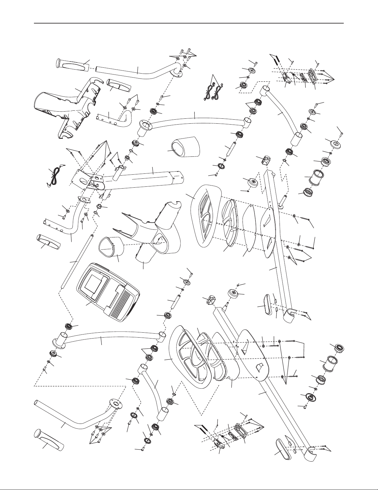
29
EXPLODED DRAWING A Model No. NTEVEL87910.1 R0111A
137
95
137
6
8
102
54
95
102
34
59
35
123
54
57
118
57
118
48
54
34
33
54
95
102
102
137
95
95
35
9
7
56
129
54
54
54
54
54
50
51
52
49
106
127
53
128
121
95
113
58
47
46
121
95
113
47
46
58
54
127
106
49
51
52
50
53
128
43
137
114
56
95
114
56
54
54
54
56
5
24
109
95
56
27
105
123
25
26
102
10
102
102
11
103
103
103
103
103
109
123
124
124
103
103
32
101
30
31
28
111
12
14
62
112
125
104
115
112
31
32
101
28
15
13
111
62
30
31
125
116
115
62
112
112
54
This manual downloaded from http://www.manualowl.com
30
67
42
110
109
65
109
66
75
75
136
136
87
76
73
74
82
96
78
89
80
91
77
88
94
84
94
98
97
92
99
76
87
71
86
86
68
55
106
70
69
64
108
107
63
108
110
72
39
86
100
107
38
61
2
37
4
37
122
39
107
1
64
41
16
100
36
36
126
3
126
16
41
41
64
60
107
133
85
132
132
132
108
103
102
102
102
103
117
108
108
108
102
103
131
130
44
93
45
29
29
29
29
29
135
139
138
90
81
79
83
101
140
141
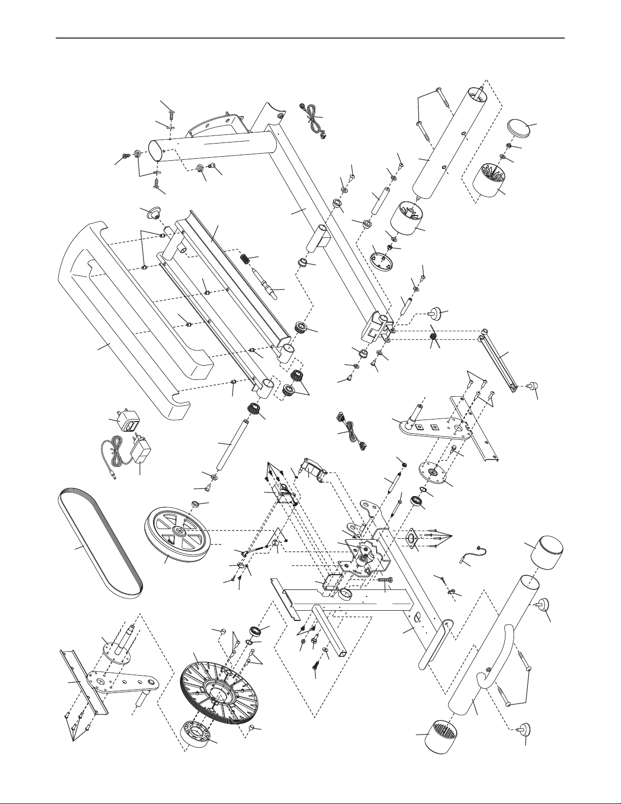
EXPLODED DRAWING B Model No. NTEVEL87910.1 R0111A
This manual downloaded from http://www.manualowl.com
31
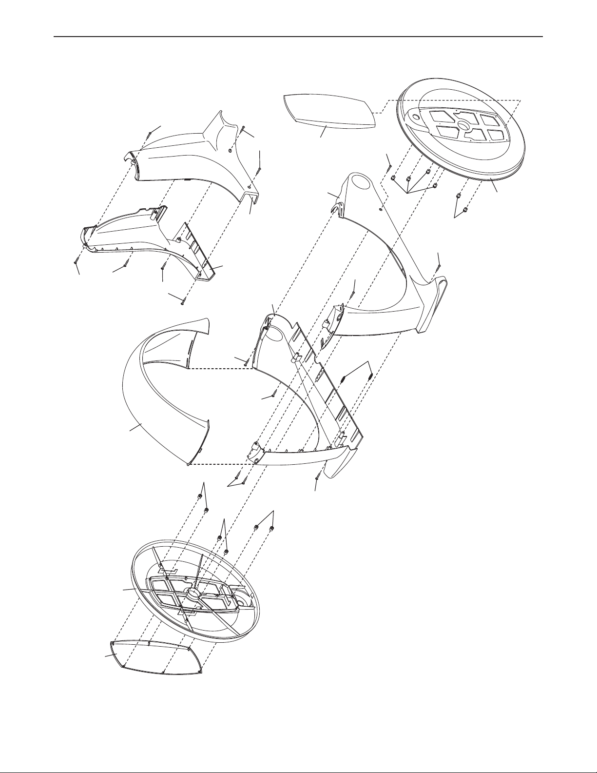
EXPLODED DRAWING C Model No. NTEVEL87910.1 R0111A
17
17
21
134
134
29
29
20
134
120
134
134
19
120
18
120
120
22
23
134
134
29
29
40
40
29
119
This manual downloaded from http://www.manualowl.com

Part No. 307549 R0111A Printed in China © 2011 ICON IP, Inc.
ORDERING REPLACEMENT PARTS
T
o order replacement parts, see the front cover of this manual. To help us assist you, please be prepared to
provide the following information when contacting us:
• the model number and serial number of the product (see the front cover of this manual)
• the name of the product (see the front cover of this manual)
• the key number and description of the replacement part(s) (see the PART LIST and the EXPLODED
DRAWING near the end of this manual)
RECYCLING INFORMATION
This electronic product must not be disposed of in municipal waste. To pre-
serve the environment, this product must be recycled after its useful life as
required by law.
Please use recycling facilities that are authorized to collect this type of waste in
your area. In doing so, you will help to conserve natural resources and improve
European standards of environmental protection. If you require more information
about safe and correct disposal methods, please contact your local city office or
the establishment where you purchased this product.
This manual downloaded from http://www.manualowl.com