www.lg.com
OWNER’S MANUAL
IPS LED MONITOR
IPS LED MONITOR MODEL
27EB22PY
Please read this manual carefully before operating your set and
retain it for future reference.
ENGLISH
1
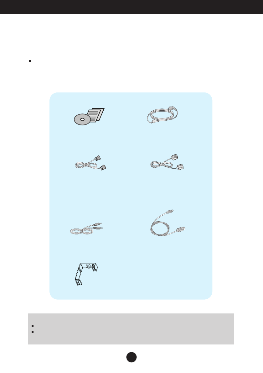
Accessories
!!! Thank for selecting LGE products !!!
Please make sure the following items are included with your
monitor. If any items are missing, contact your dealer.
User's Guide/Cards
Power Cord
15-pin D-Sub Signal Cable
(To set it up, this signal cable may be
attached to this product before
shipping out.)
DVI-D Signal Cable
(This feature is not available in all
countries.)
NOTE
This accessories may look different from those shown here.
User must use shielded signal interface cables (D-sub 15 pin cable, DVI-D cable) with ferrite
cores (core in the connector) to maintain standard compliance for the product.
Audio Cable
USB Cable
Cable Holder
2
Connecting the Display
Before setting up the monitor, ensure that the power to the monitor,
the computer system, and other attached devices are turned off.
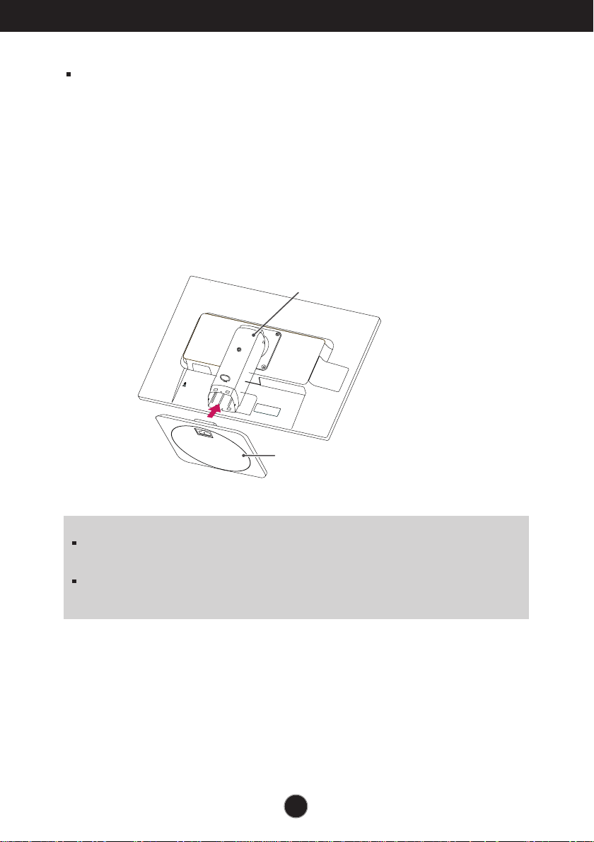
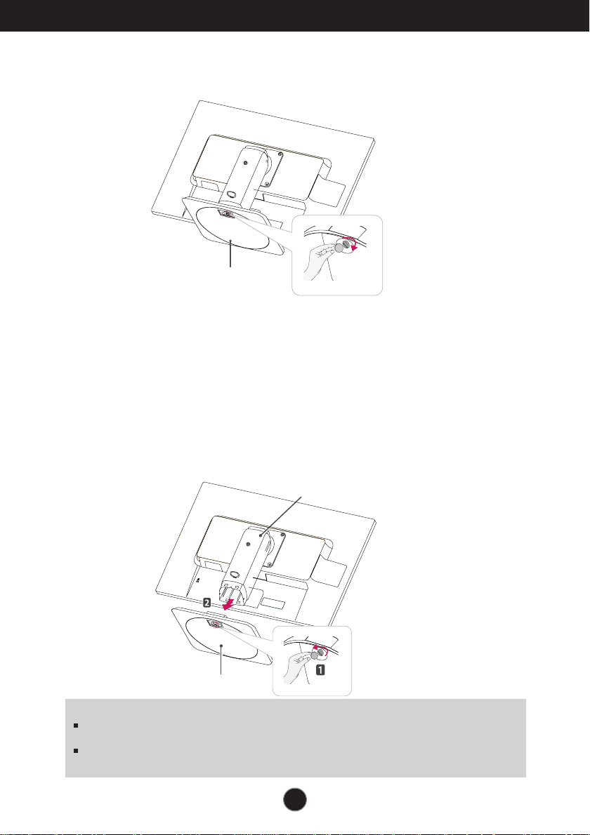
Connecting the stand base
1. Place the monitor with its front facing downward on a cushion or soft cloth.
2
.
Assemble the Stand Base into the Stand Body.
Be sure don't pull out the Stop Pin and make the Stand Base direction as shown.
WARNING
The tape and locking pin may only be removed from those monitors equipped with a
standing base when the base is pulled up. Otherwise, you may be injured by the protruding
sections of the stand.
Product Handling with Care: When you lift up or move the product, Do Not hold or touch the
front part of LCD panel. It will damage the panel. (Please hold the Stand Body or plastic cover of
the product.)
Stand Base
Stand Body
3
Connecting the Display
IMPORTANT
This illustration depicts the general model of connection. Your monitor may differ from the items
shown in the picture.
Do not carry the product upside down holding only the stand base. The product may fall and get
damaged or injure your foot.
3. Use a coin on the back of the stand base and turn the screw clockwise to tighten.
4.
Lift and turn the monitor to face towards the front after the connection is
made to the female part of the cable you're attaching.
Removing the stand base
1. Place the monitor with its front facing downward on a cushion or soft cloth.
2. When you desire to disintegrate the monitor from the stand base, use a coin to turn the
screw counterclockwise.
Stand Base
Stand Base
Stand Body
4
Connecting the Display
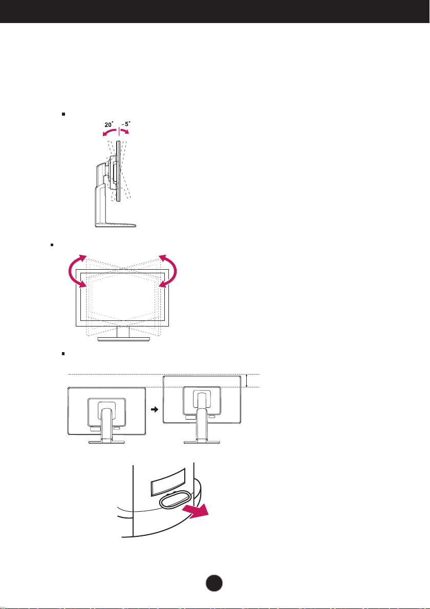
Height Range : maximum 5.12 inches (130.0 mm)
* Please be sure to
remove the Locking
pin to adjust the height.
130.0mm
Positioning your display
After installation, adjust the angle as shown below.
1. Adjust the position of the panel in various ways for maximum comfort.
Tilt Range
Swivel Range : 355˚
5
Connecting the Display
ERGONOMIC
I
t is recommended that in order to maintain an ergonomic and comfortable viewing position, the forward tilt
angle of the monitor should not exceed 5 degrees.
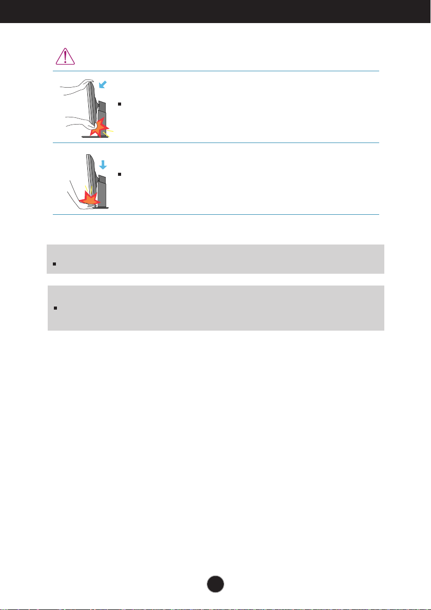
WARNING
You do not need to replace the Locking pin after it is removed, to adjust its height.
When adjusting the angle of the screen, do not put your finger(s) in
between the head of the monitor and the stand body. You can hurt your
finger(s).
When adjusting the height of the screen, do not put your finger(s) in
between the head of the monitor and the stand base. You can hurt your
finger(s).
6
Connecting the Display
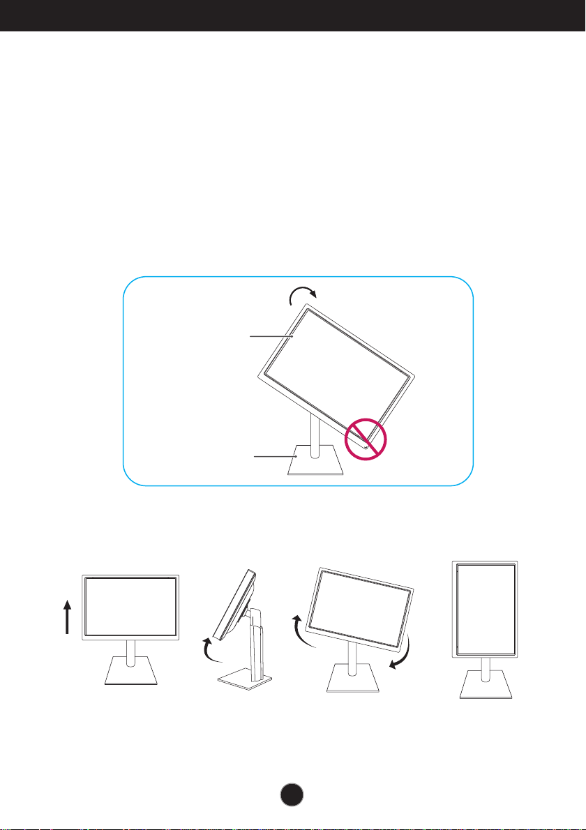
-The pivot function allows you to rotate the screen 90 degrees clockwise.
1.
Lift the monitor to its highest height to utilize the Pivot function.
2. Landscape & Portrait : You can rotate the panel 90
o
clockwise.
Please be cautious and avoid contact between the monitor head and the
Stand Base when rotating the screen to access the Pivot function. If the
monitor head touches the Stand Base, then the Stand Base could crack.
3
.
Be careful with the cables when rotating the screen.
Using the Pivot function
Stand section
Head section
7
Connecting the Display
A
B
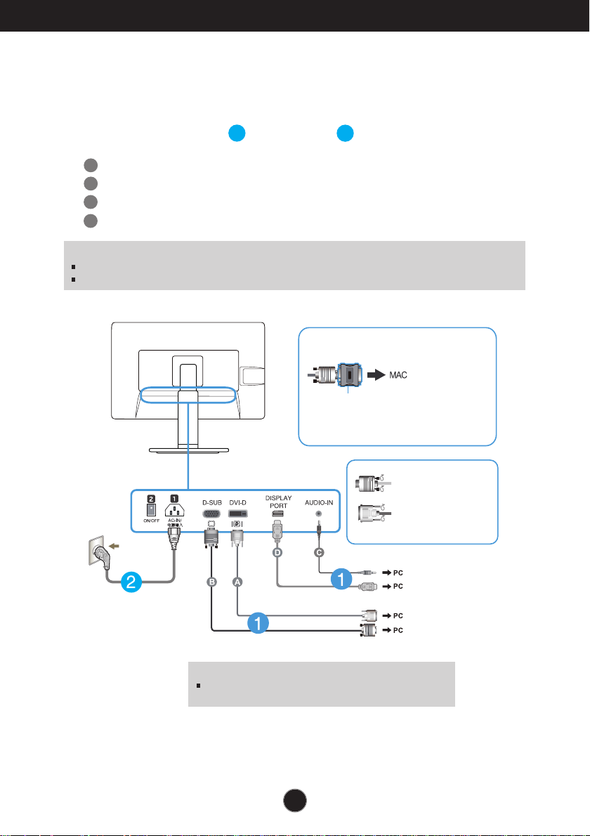
Connect DVI-D(Digital signal) Cable
Connect D-sub(Analog signal) Cable
1. Before setting up the monitor, ensure that the power to the monitor, the computer
system, and other attached devices is turned off.
2.
Connect signal input cable and power cord in order, then tighten the screw
of the signal cable.
Connecting with the PC
1
2
Wall-outlet type
Mac adapter : For Apple Macintosh use, a
separate plug adapter is needed to change the
15 pin high density (3 row) D-sub VGA
connector on the supplied cable to a 15 pin 2
row connector.
When using a D-Sub signal input cable
connector for Macintosh
Varies according to model.
DVI-D (This feature is not available in all countries.)
Connect the signal
input cable and tighten
it up by turning in the
direction of the arrow
as shown in the figure.
Warning
Please pull the DVI cable first,then pull DisplayPort cable,
for protect your finger.
NOTE
This is a simplified representation of the rear view.
This rear view represents a general model; your display may differ from the view as shown.
C
Connect Audio Cable
D
Connect DisplayPort Cable (Separate purchase)
8
Connecting the Display
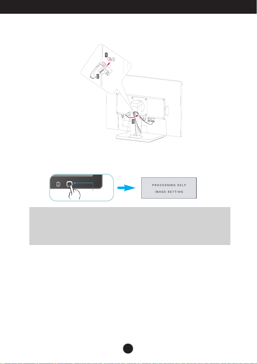
NOTE
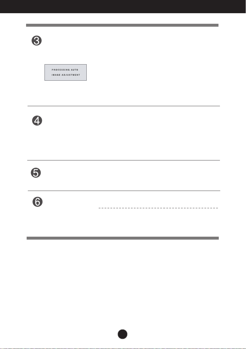
‘ Self Image Setting Function’? This function provides the user with optimal display
settings.When the user connects the monitor for the first time, this function automatically adjusts
the display to optimal settings for individual input signals.
‘AUTO’ Function? When you encounter problems such as blurry screen, blurred letters, screen
flicker or tilted screen while using the device or after changing screen resolution, press the
AUTO function button to improve resolution.
4. Press the power button on the front panel to turn the power on. When monitor power is
turned on, the 'Self Image Setting Function' is executed automatically.
(Only Analog Mode)
Power Button
3. Put the power cord and cables into the cable holder.
Connecting the Display
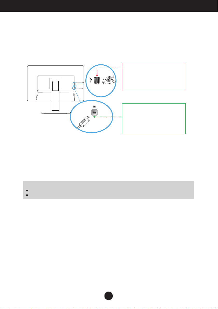
Connecting the USB(Universal Serial Bus) Cable
1. You can use the USB port at the back of the monitor to connect peripherals (USB
mouse, USB keyboard, etc.) to the monitor, not to the computer.
2.
The monitor’s USB terminal supports USB 2.0 and High Speed cables.
Two USB Downstream ports
Connect these ports to a mouse,
USB keyboard,memory stick with
current spec under 100mA.
One USB Upstream port
Connect this port to the downstream
port of a computer, laptop or USB
monitor (Your computer or USB
monitor must support USB and have
USB ports).
NOTE
This is a simplified representation of the rear view.
This rear view represents a general model; your display may differ from the view as shown.
9
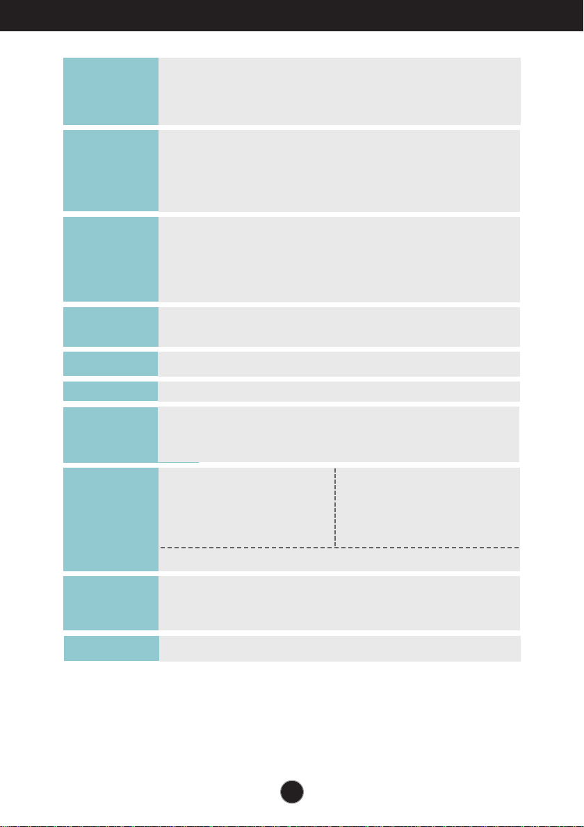
Control Panel Functions
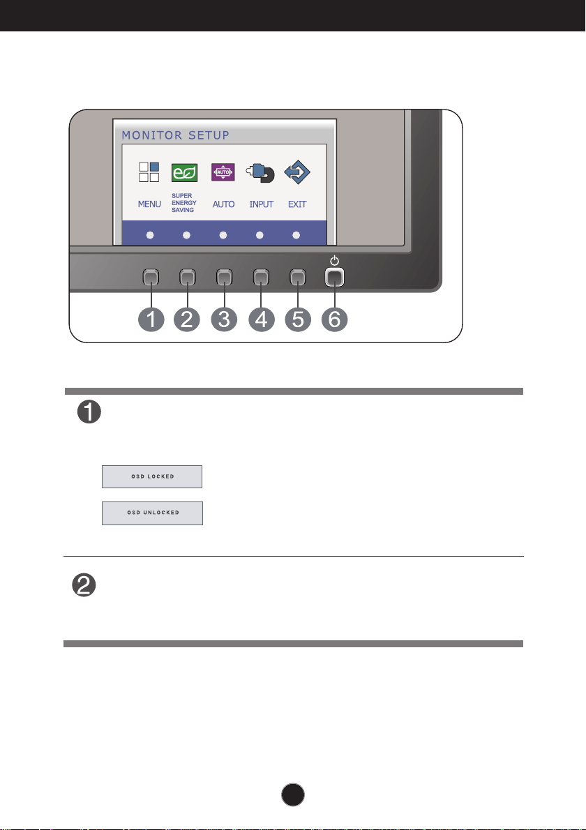
Front Panel Controls
MENU Button
OSD LOCKED/UNLOCKED
This function allows you to lock the current control
settings, so that they cannot be inadvertently changed.
Press and hold the MENU button for several seconds.
The message "OSD LOCKED" should appear.
You can unlock the OSD controls at any time by pushing
the MENU button for several seconds. The message
"OSD UNLOCKED" should appear.
SUPER ENERGY
SAVING Button
Use this button to enter
SUPER ENERGY SAVING
menu.For more information, refer to page 17.
10
Control Panel Functions
INPUT Button
When two input signals are connected, you can select the
input signal (D-SUB/DVI/DP) you want. When only one
signal is connected, it is automatically detected. The default
setting is D-Sub.
(SOURCE Hot key)
Exit the OSD(On Screen Display).
EXIT Button
AUTO Button
AUTO IMAGE ADJUSTMENT
When adjusting your display settings, always press
the AUTO button before entering the On Screen
Display(OSD). (Only Analog Mode)
This will automatically adjust your display image to
the ideal settings for the current screen resolution
size (display mode).
The best display mode is
27EB22PY : 1920 x 1080
Use this button to turn the display on or off.
The power indicator stays white if the display is running
properly (On Mode). If the display is in Sleep Mode
(Energy Saving), the power indicator is blinking white.
Power Button &
Power Indicator
11
On Screen Display (OSD) Control Adjustment
Screen Adjustment
Making adjustments to the image size, position and operating
parameters of the display is quick and easy with the On Screen
Display Control system.
A short example is given below to familiarize you with the use of the
controls. The following section is an outline of the available
adjustments and selections you can make using the OSD.
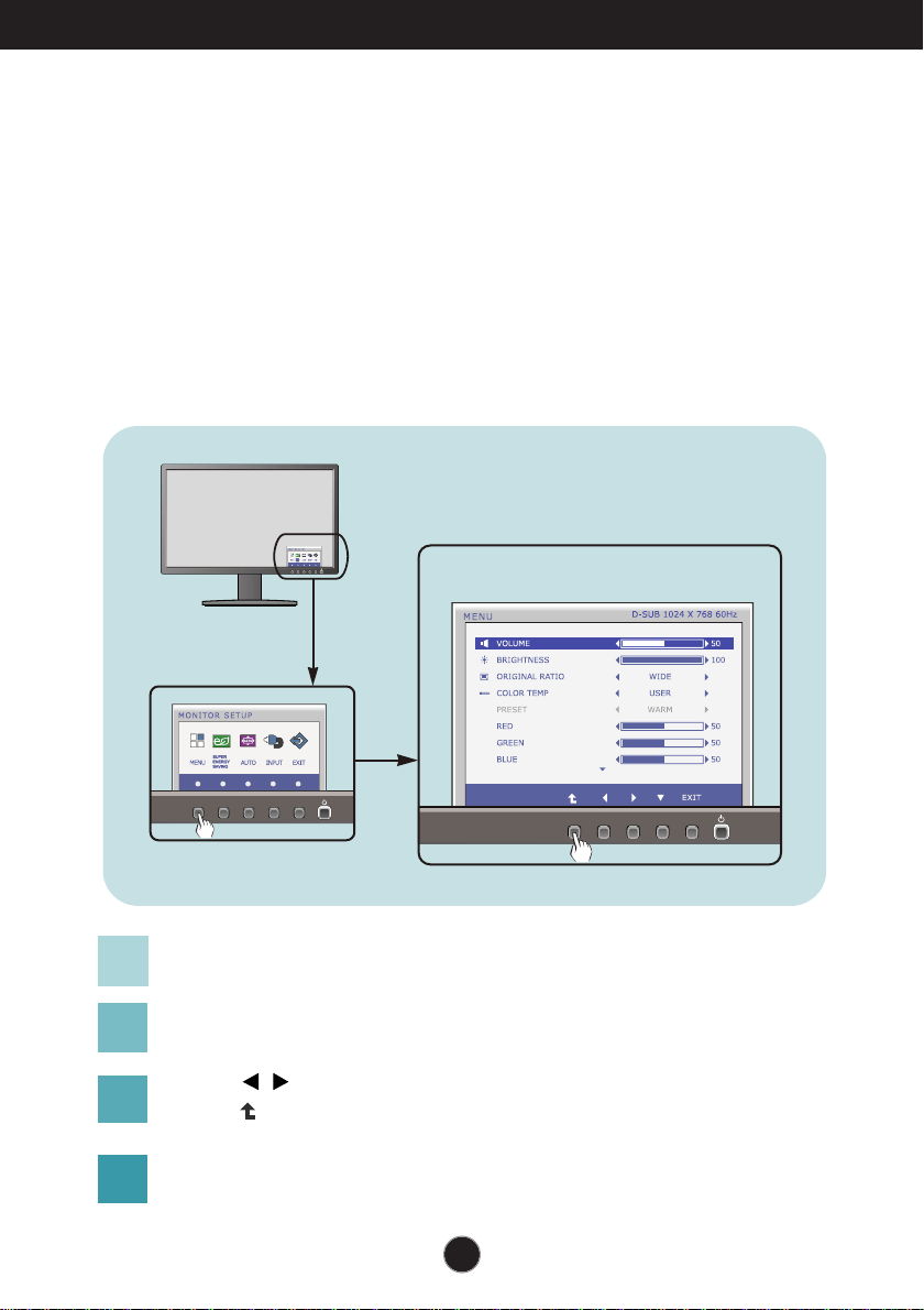
To make adjustments in the On Screen Display, follow these steps:
Press the discretionary Button, then the main menu of the OSD appears.
To access a control, use the corresponding Buttons.
Use the / Buttons to adjust the image to the desired level.
Use the Button to select other sub-menu items.
Press the EXIT Button to exit from the OSD.
1
2
3
4
12
On Screen Display(OSD) Selection and Adjustment
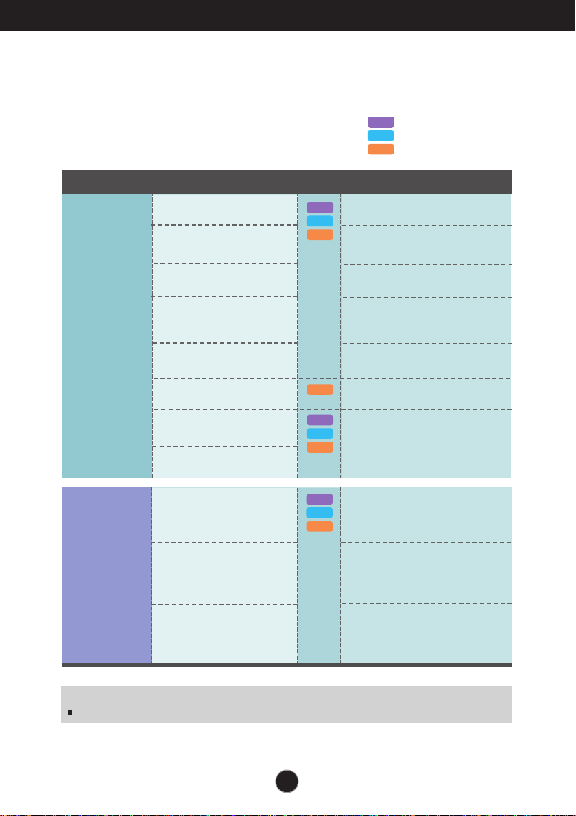
The following table indicates all the On Screen Display control, adjustment,
and setting menus.
: D-SUB(Analog signal) input
: DVI-D(Digital signal) input
: DP(DisplayPort signal) input
DSUB
DVI-D
To adjust the volume
To customize the screen status
for a user's operating
environment
To adjust the contrast of the
screen
To customize the color of the
screen
MENU
To adjust the brightness of the
screen
To adjust the image size
Main menu Sub-menu
Supported input
Description
VOLUME
BRIGHTNESS
ORIGINAL RATIO
COLOR TEMP
(USER / PRESET)
CONTRAST
BLACK LEVEL
LANGUAGE
FACTORY RESET
SUPER
ENERGY
SAVING
Turn on the SUPER ENERGY
SAVING function.
Turn off the SUPER ENERGY
SAVING function.
Initialize the SUPER ENERGY
SAVING and set to "OFF" mode.
ON
OFF
RESET
NOTE
The order of icons may differ depending on the model (13~19).
DP
DSUB
DVI-D
DP
DSUB
DVI-D
DP
DSUB
DVI-D
DP
DP
To set offset level
13
On Screen Display(OSD) Selection and Adjustment
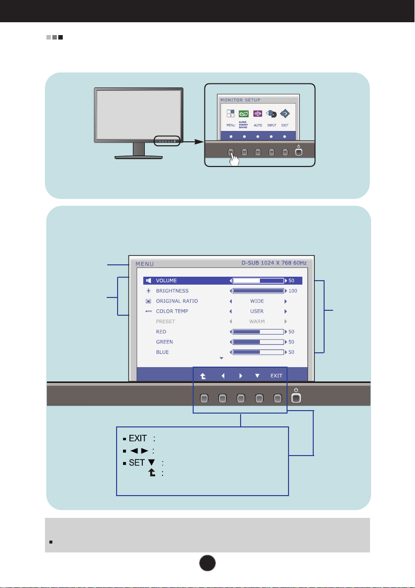
You were introduced to the procedure of selecting and adjusting an item
using the OSD system. Listed below are the icons, icon names, and icon
descriptions of the all items shown on the Menu.
Sub-
menus
NOTE
OSD (On Screen Display) menu languages on the monitor may differ from the manual.
Menu Name
Icons
Button
Tip
Exit
Adjust (Decrease/Increase)
Press the MENU Button, then the main menu of the OSD appears.
Select another sub-menu
Restart to select sub-menu
14
On Screen Display(OSD) Selection and Adjustment
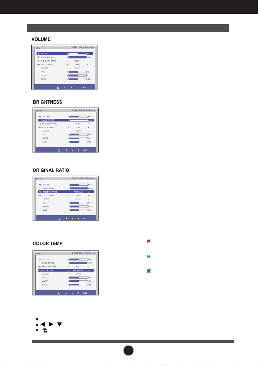
Main menu Sub menu Description
To adjust the brightness of the screen.
Change the input image signal ratio to
original.
WIDE
ORIGINAL
Switch to full screen mode according to
input image signal.
* This function works only if input
resolution is lower than monitor ratio
(16:9).
Exit : Exit
, , : Move
: Select another sub-menu
PRESET
RED
Set your own red color levels.
GREEN
Set your own green color levels.
BLUE
Set your own blue color levels.
Select the screen color.
• WARM: Set the screen to warm
color temperature .
• MEDIUM: Set the screen to medium
color temperature.
• COOL: Set the screen to cool color
temperature.
USER
To adjust the volume of headphone/Speaker.
15
On Screen Display(OSD) Selection and Adjustment
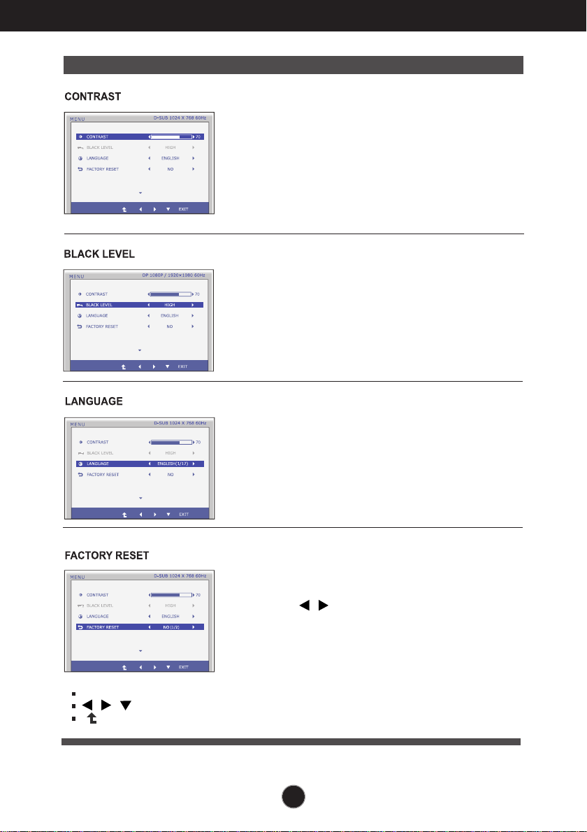
Main menu Description
To choose the language in which the
control names are displayed.
Press the , buttons to reset
immediately.
Restore all factory default settings except
"LANGUAGE."
To adjust the contrast of the screen.
Exit : Exit
, , : Move
: Select another sub-menu
You can set the offset level. If you select
'HIGH', the screen will be bright and if you
select ‘LOW’, the screen will be dark.
* Offset? As the criteria for video signal, it is the
darkest screen the monitor can show.
(only for DP input)
16
On Screen Display(OSD) Selection and Adjustment
You were introduced to the procedure of selecting and adjusting an item
using the OSD system. Listed below are the icons, icon names, and icon
descriptions of the all items shown on the Menu.
Sub-menus
NOTE
OSD (On Screen Display) menu languages on the monitor may differ from the manual.
Menu Name
Icons
Button
Tip
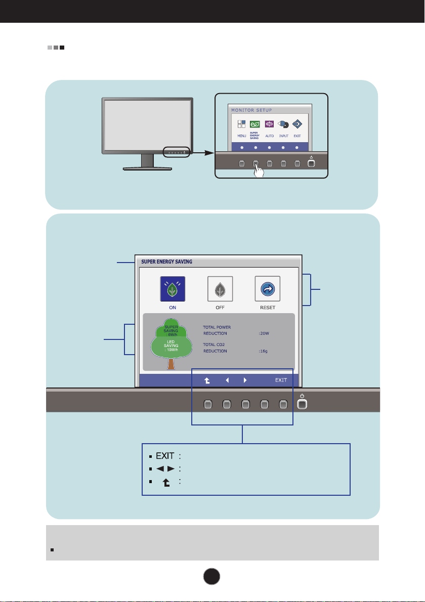
Press the SUPER ENERGY SAVING Button, then the main menu of the
OSD appears.
Exit
Move
Restart to select sub-menu
17
On Screen Display(OSD) Selection and Adjustment
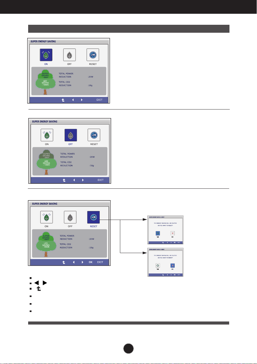
Main menu Sub menu Description
Exit : Exit
, : Move
: Select another sub-menu
Turn on the SUPER ENERGY
SAVING fuction.
When current setting value is
ON,the SUPER SAVING color is
green.
Turn off the SUPER ENERGY
SAVING function.Now the monitor
is LED SAVING function.
When current setting value is
OFF,the SUPER SAVING color is
gray.
Clear the TOTAL POWER
REDUCTION and TOTAL CO2
REDUCTION values.
OK : Select
TOTAL POWER REDUCTION : How much power is saved during using the monitor.
TOTAL CO2 REDUCTION : Change the TOTAL POWER REDUCTION to CO2.
ON
OFF
RESET
18
On Screen Display(OSD) Selection and Adjustment
SUPER SAVING
LED SAVING
6
10
27 inch
Saving Data depends on the Panel. So,those values should be different from
each panel and panel vendor.
LG accumulate those values using integrated function with 10 minutes
broadcast video signal.
LED Saving means that how much power can be saved using WLED Panel
instead of CCFL panel.
SUPER Saving means that how much power can be more saved using
SUPER ENERGY SAVING function.
NOTE
SAVING DATA(W/h):
19
Troubleshooting
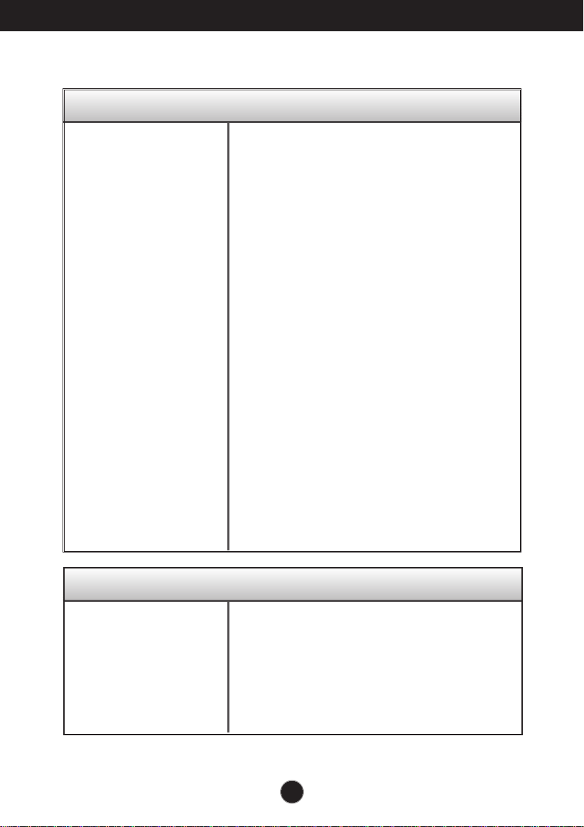
No image appears
Check the following before calling for service.
No image appears
Do you see a "OSD LOCKED" message on the screen?
● Is the power cord of the
display connected?
● Is the power indicator
light on?
● Is the power indicator
flickering?
● Do you see an "OUT OF
RANGE" message on
the screen?
● Do you see a "CHECK
SIGNAL CABLE"
message on the
screen?
•
Check and see if the power cord is connected
properly to the power outlet.
•
Press the Power button.
•
If the display is in power saving mode, try moving
the mouse or pressing any key on the keyboard to
bring up the screen.
• Try to turn on the PC
.
•
This message appears when the signal from the
PC (video card) is out of horizontal or vertical
frequency range of the display. See the
'Specifications' section of this manual and
configure your display again.
•
This message appears when the signal cable
between your PC and your display is not
connected. Check the signal cable and try again.
• You can secure the current control settings,
so that they cannot be inadvertently changed.
You can unlock the OSD controls at any time
by pushing the MENU button for several
seconds: the message
“OSD UNLOCKED” will appear.
●
Do you see “OSD
LOCKED” when you
push MENU button?
20
Troubleshooting
IMPORTANT
Check Control Panel --> Display --> Settings and see if the frequency or the
resolution were changed. If yes, readjust the video card to the recommend
resolution.
If the recommended resolution (optimal resolution) is not selected, letters may be
blurred and the screen may be dimmed, truncated or biased. Make sure to select
the recommend resolution.
The setting method can differ by computer and O/S (Operation System),
and resolution mentioned above may not be supported by the video card
performance. In this case, please ask to the computer or the video card
manufacturer.
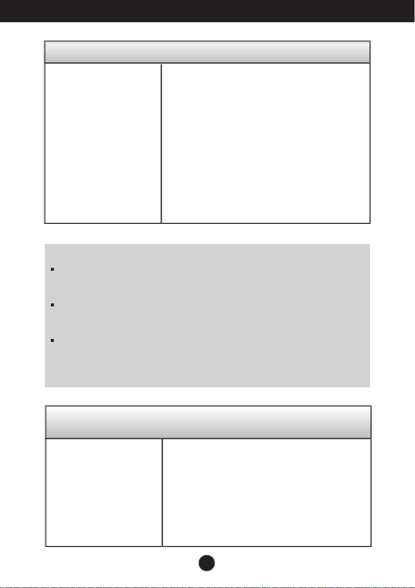
Display image is incorrect
● The screen color is
mono or abnormal.
● The screen blinks.
•
Check if the signal cable is properly connected
and use a screwdriver to fasten if necessary.
•
Make sure the video card is properly inserted in
the slot.
•
Set the color setting higher than 24 bits (true color)
at Control Panel - Settings.
•
Check if the screen is set to interlace mode and if
yes, change it to the recommend resolution.
Do you see an "Unrecognized monitor, Plug&Play (VESA
DDC) monitor found" message?
●
Have you installed the
display driver?
•
Be sure to install the display driver from the display
driver CD (or diskette) that comes with your
display. Or, you can also download the driver from
our web site: http://www.lg.com.
•
Make sure to check if the video card supports
Plug&Play function.
21
Specifications
68.6
cm (
27
inch) Flat Panel Active matrix-TFT LCD
Anti-Glare coating
Visible diagonal size : 68.6 cm
0.3114 x 0.3114 mm (Pixel pitch)
Display
Horizontal Freq. 30 kHz to 83 kHz (Automatic)
Vertical Freq. Analog,Digital:56 Hz to 75 Hz (Automatic)
DisplayPort:56 Hz to 61 Hz (Automatic)
Input Form Separate Sync.
Digital
Sync Input
Signal Input 15 pin D-Sub Connector
DVI-D Connector (Digital)
20 pin DisplayPort Connector
Input Form RGB Analog (0.7 Vp-p/ 75 ohm), Digital
DisplayPort
Video Input
Max VESA 1920 x 1080 @60 Hz
Recommend VESA 1920x 1080 @60 Hz
Resolution
Plug&Play
On Mode
: 27
W(Typ.)
Sleep Mode ≤ 0.3 W
Off Mode ≤ 0.3 W
Power
Consumption
With Stand
Width 64.4 cm ( 25.35 inch)
Height 41.0 cm ( 16.14 inch)
(Min.)
54.0 cm ( 21.26 inch)
(Max.)
Depth 25.9 cm ( 10.20 inch)
Weight(excl. packing) 6.5 kg (14.44 lb)
Dimensions
& Weight
Tilt -
5
˚
to 20
˚
Swivel 355˚
Height 130 mm / 5.12 inch
Range
AC 100 - 240 V~ 50 / 60 Hz 1.5 A
Power Input
DDC 2B(Digital,DisplayPort),DDC2AB(Anlaog)
Without Stand
Width 64.4 cm ( 25.35 inch)
Height 38.7 cm ( 15.24 inch)
Depth 6.4 cm ( 2.52 inch)
USB
USB2.0
22
Specifications
Operating Conditions
Temperature 10 ˚C to 35 ˚C
Humidity 10 % to 80 % non-Condensing
Storage Conditions
Temperature -20 ˚C to 60 ˚C
Humidity 5 % to 90 % non-Condensing
Environment
al Conditions
Attached ( ), Detached ( O )
Stand Base
Wall-outlet type
Power cord
NOTE
Information in this document is subject to change without notice.
23
Specifications
Preset Modes (Resolution)
Display Modes (Resolution) Horizontal Freq. (kHz) Vertical Freq. (Hz)
*Recommend Mode
1
2
3
4
5
6
7
8
9
10
11
*12
720 x 400
640 x 480
640 x 480
800 x 600
800 x 600
1024 x 768
1024 x 768
1152 x 864
1280 x 1024
1280 x 1024
1680 x 1050
1920 x 1080
31.468
31.469
37.500
37.879
46.875
48.363
60.023
67.500
63.981
79.976
65.290
67.500
70
60
75
60
75
60
75
75
60
75
60
60
27EB22PY
Indicator
On Mode
Sleep Mode
Off Mode
White
White Blinking
Off
LED Color
MODE
24
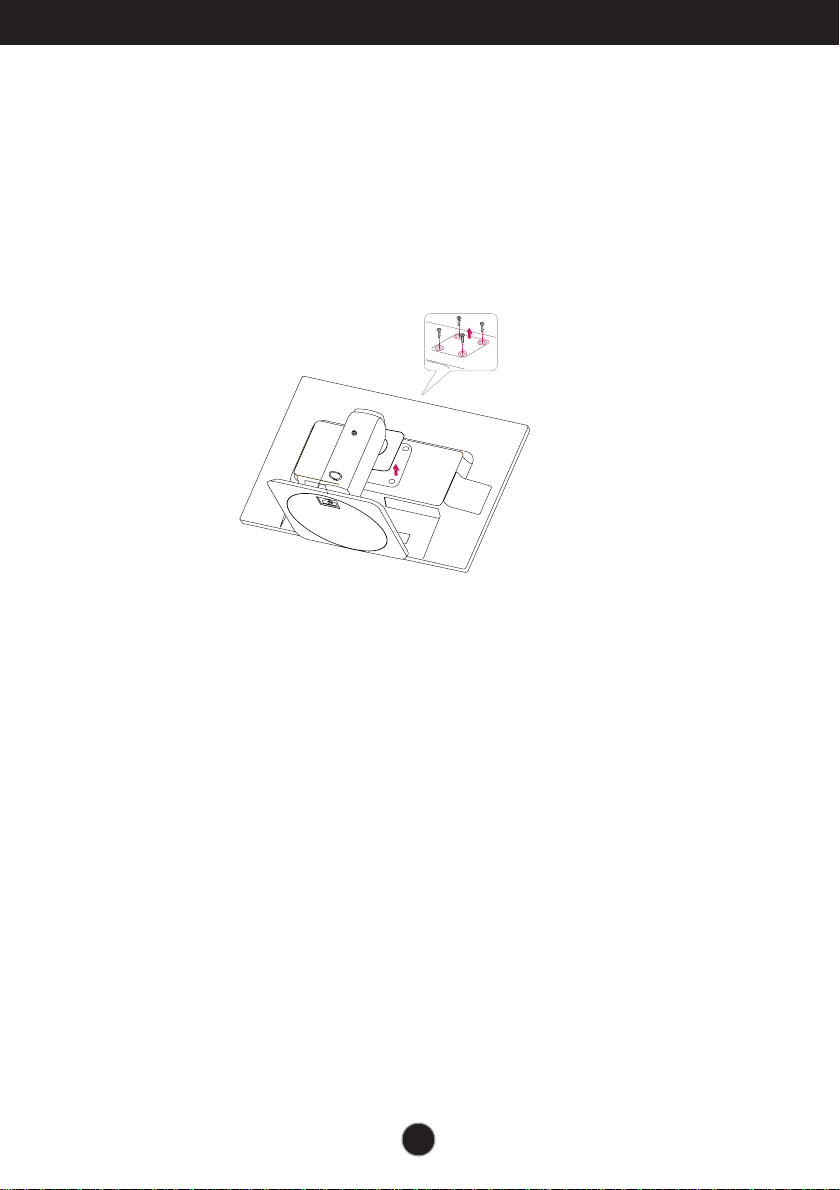
Installing the Wall mount plate
This monitor satisfies the specifications of the Wall mount plate or
the interchange device.
1.
After moving the product to face downward, make sure to place it on a soft
2.
Separate the head and the stand with the use of a screwdriver.
cloth or a cushion to avoid surface damage.
25
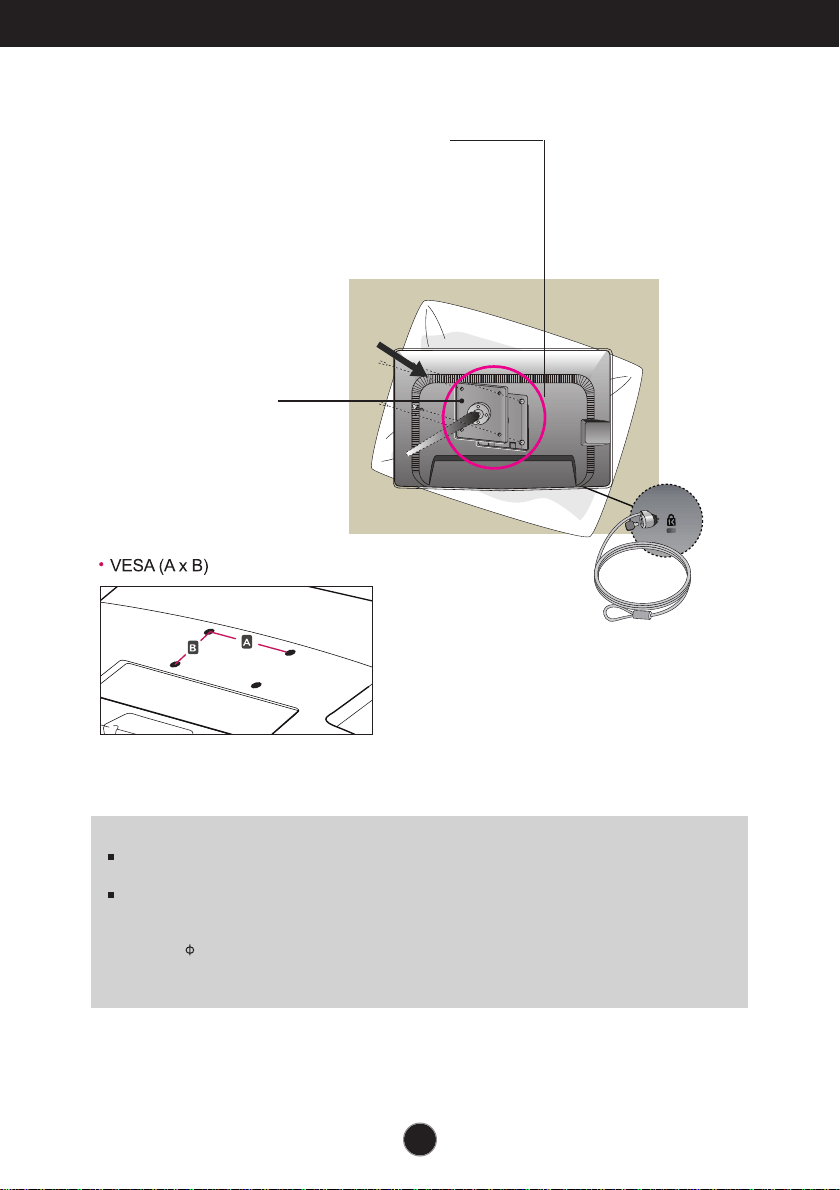
Wall mount plate(Separate purchase)
This is stand-type or wall mount type and is
connectable with Wall mount plate.
Please refer to the installation guide for more
details, which is provided when Wall mount plate
is purchased.
Kensington Security Slot
Connected to a locking
cable that can be
purchased separately at
most computer stores.
3.
Install the Wall mount plate.
<Screw Mounting Interface Dimension>
Hole spacing : 200 mm x 100 mm.
NOTE
VESA compatible only with respect to screw mounting interface dimensions and mounting screw
specifications
Please use VESA standard as below.
* 784.8 mm and under (30.9 inch)
- Wall Mount Pad Thickness : 2.6 mm
- Screw : 4.0 mm x Pitch 0.7 mm x Length 10 mm
* 787.4 mm and above (31.0 inch)
- Please use VESA standard wall mount pad and screws.
Wall Mount pad
Installing the Wall mount plate
26
Make sure to read the Safety Precautions
before using the product.
Keep the OWNER’S MANUAL(CD) in an
accessible place for furture reference.
The model and serial number of the SET is
located on the back or one side of the SET.
Record it below should you ever need service.
MODEL
SERIAL
As an ENERGY STAR Partner LGE U. S. A.,Inc.
has determined that this product meets the
ENERGY STAR guidelines for energy efficiency.
ENERGY STAR is a set of power-saving
guidelines issued by the U.S.Environmental
Protection Agency(EPA).
*above information is only for USA FCC Regulatory
Declaration of Conformity
Trade Name: LG
Model : 27EB22PYC
Res
pon
sible Party: LG Electronics Inc.
Address : 1000 Sylvan Ave. Englewood Cliffs
NJ 07632 U.S.A
TEL: 201-266-2534