

GLE
Operator's Manual
Mercedes-Benz
Your Operator's Manual
Digital form inside the vehicle
Familiarize yourself with the contents of the Operator's Manual directly via your
vehicle's multimedia system (Menu item "Vehicle").
Booklet inside the vehicle
In addition to the vehicle's Operator's Manual, you can obtain the complete multi-
media system Supplement from your authorized Mercedes-Benz Center.
Digital form via the Internet
You can find the Operator's Manual on the Mercedes-Benz homepage.
Digital form as an App
The Mercedes-Benz Guides App is available for free on the Apple
®
App store or Google
Play.
Apple® iOS Android™
Order no. P166 0521 13 Part no. 166 584 36 09 Edition A 2019
É16658436096ËÍ
1665843609
GLE Operator's Manual
Welcome to the world of Mercedes-Benz
We urge you to read this Operator's Manual
carefully and familiarize yourself with the vehi-
cle before driving. For your own safety and a
longer vehicle life, follow the instructions and
warning notices in this Operator's Manual.
Ignoring them could result in damage to the
vehicle or personal injury to you or others.
Vehicle damage caused by failure to follow
instructions is not covered by the Mercedes-
Benz Limited Warranty.
The equipment or product designation of your
vehicle may vary depending on:
R
Model
R
Order
R
Country specification
R
Availability
Mercedes-Benz therefore reserves the right to
introduce changes in the following areas:
R
Design
R
Equipment
R
Technical features
The equipment in your vehicle may therefore
differ from that shown in the descriptions and
illustrations.
The following are integral components of the
vehicle:
R
Digital Operator's Manual
R
Printed Operator's Manual
R
Maintenance Booklet
R
Equipment-dependent supplements
Keep these documents in the vehicle at all
times. If you sell the vehicle, always pass all
documents on to the new owner.
Your Operator's Manual:
Digital form inside the vehicle
The Digital Operator's Manual provides
comprehensive and specifically adapted
information on your vehicle's equipment
and multimedia system. It contains infor-
mative animations, individual language
settings and an intuitive search function.
Booklet inside the vehicle
In addition to this manual and the afore-
mentioned digital media, you also have the
option to obtain a comprehensive printed
version of the Supplement for your multi-
media system from your authorized
Mercedes-Benz Center.
Digital form via the Internet
The Operator's Manual on the Internet pro-
vides easy access to all information
regarding your vehicle and multimedia sys-
tem. It also provides helpful animations,
interesting background information and a
wide array of search options.
Digital form as an App
Using the Mercedes-Benz Guides App, you
can view all the information on your vehicle
and multimedia system via mobile Internet
or download it independently of network
access. Available for smartphones or tab-
lets.
You can also use the Mercedes-Benz Guides
App:
Please note that the Mercedes-Benz Guides App
may not yet be available in your country.
Mercedes-Benz USA, LLC
Mercedes-Benz Canada, Inc.
A Daimler Company
1665843609
É16658436096ËÍ

Index ....................................................... 4
Digital Operator's Manual .................. 26
Introduction ...........................................26
Operation ............................................... 26
Introduction ......................................... 27
Protecting the environment ...................27
Genuine Mercedes-Benz parts ...............27
Operator's Manual ................................. 28
Service and vehicle operation ................28
Operating safety .................................... 30
QR code for rescue card ........................ 32
Data stored in the vehicle ......................32
Information on copyright ....................... 35
At a glance ........................................... 36
Cockpit .................................................. 36
Instrument cluster .................................37
Multifunction steering wheel ................. 38
Center console ...................................... 39
Overhead control panel .........................42
Door control panel ................................. 43
Safety ................................................... 44
Panic alarm ............................................ 44
Occupant safety .................................... 44
Children in the vehicle ........................... 59
Pets in the vehicle ................................. 65
Driving safety systems ........................... 66
Protection against theft .........................75
Opening and closing ........................... 77
SmartKey ............................................... 77
Doors ..................................................... 83
Cargo compartment ...............................84
Side windows ......................................... 88
Sliding sunroof ....................................... 92
Seats, steering wheel and mirrors .... 97
Correct driver's seat position ................ 97
Seats ..................................................... 97
Steering wheel ..................................... 103
Mirrors ................................................. 105
Memory function ................................. 108
Lights and windshield wipers .......... 110
Exterior lighting ................................... 110
Interior lighting .................................... 114
Replacing bulbs (vehicles with LED
headlamps) .......................................... 115
Replacing bulbs (vehicles with halo-
gen headlamps) ................................... 115
Windshield wipers ................................ 117
Climate control ................................. 122
Overview of climate control systems ... 122
Operating the climate control sys-
tems .................................................... 127
Setting the air vents ............................ 132
Driving and parking .......................... 134
Notes on breaking-in a new vehicle ..... 134
Driving ................................................. 134
DYNAMIC SELECT controller ............... 142
Automatic transmission ....................... 143
Refueling ............................................. 150
Parking ................................................ 156
Driving tips .......................................... 159
Driving systems ................................... 169
Towing a trailer .................................... 220
Bicycle rack ......................................... 226
Notes on towing vehicles ..................... 228
On-board computer and displays .... 229
Important safety notes ........................ 229
Displays and operation ........................ 229
Menus and submenus ......................... 232
Display messages ................................ 244
Warning and indicator lamps in the
instrument cluster ............................... 274
Multimedia system ........................... 287
General notes ...................................... 287
Important safety notes ........................ 287
Function restrictions ............................ 287
Operating system ................................ 288
2
Contents

Stowage and features ...................... 295
Stowage areas .....................................295
Features .............................................. 304
Maintenance and care ...................... 321
Engine compartment ........................... 321
ASSYST PLUS ...................................... 325
Care ..................................................... 326
Breakdown assistance ..................... 334
Where will I find...? .............................. 334
Flat tire ................................................ 335
Battery (vehicle) .................................. 340
Jump-starting ....................................... 343
Towing and tow-starting ......................345
Fuses ................................................... 349
Wheels and tires ............................... 351
Important safety notes ........................ 351
Operation ............................................ 351
Winter operation .................................. 353
Tire pressure ....................................... 354
Loading the vehicle .............................. 361
All about wheels and tires ................... 364
Changing a wheel ................................ 371
Wheel and tire combinations ...............376
Emergency spare wheel ....................... 376
Technical data ................................... 381
Information regarding technical data ... 381
Vehicle electronics .............................. 381
Identification plates .............................382
Service products and filling capaci-
ties ...................................................... 383
Vehicle data ......................................... 390
Vehicle data for off-road driving .......... 392
Trailer tow hitch ................................... 394
Contents
3

1, 2, 3 ...
4ETS (Electronic Traction System)
see ETS/4ETS (Electronic Trac-
tion System)
4MATIC (permanent four-wheel
drive) .................................................. 214
12 V socket
see Sockets
115 V socket ...................................... 308
360° camera
Cleaning .........................................331
Display in the multimedia system .. 201
Function/notes .............................199
A
ABS (Anti-lock Braking System)
Display message ............................ 245
Function/notes ................................ 66
Important safety notes .................... 66
Warning lamp ................................. 277
Accident
Automatic measures after an acci-
dent ................................................. 59
Activating media mode
General notes ................................ 293
Activating/deactivating cooling
with air dehumidification ................. 127
Active Blind Spot Assist
Activating/deactivating (on-
board computer) ............................ 238
Display message ............................ 265
Function/information .................... 209
Trailer towing ................................. 211
Active Brake Assist
Activating or deactivating .............. 238
Display message ............................ 250
Function/notes ................................ 67
Active Brake Assist with cross-
traffic function
Activating or deactivating .............. 238
Display message ............................ 251
Function/notes ................................ 72
Important safety notes .................... 73
Warning lamp ................................. 285
Active Curve System
Display message ............................ 262
Function/notes ............................. 185
Active Distance Assist DISTRONIC
Activating ....................................... 173
Activation conditions ..................... 173
Cruise control lever ....................... 173
Deactivating ................................... 175
Display message ............................ 266
Displays on the instrument clus-
ter .................................................. 176
Driving tips .................................... 177
Function/notes ............................. 171
Important safety notes .................. 172
Setting the specified minimum
distance ......................................... 175
Stopping ........................................ 174
Warning lamp ................................. 285
Active Lane Keeping Assist
Activating/deactivating (on-
board computer) ............................ 238
Display message ............................ 264
Function/information .................... 211
Trailer towing ................................. 214
Active light function ......................... 112
Active Parking Assist
Canceling ....................................... 195
Detecting parking spaces .............. 192
Display message ............................ 265
Exiting a parking space .................. 194
Function/notes ............................. 191
Important safety notes .................. 191
Parking .......................................... 193
Active Steering Assist
Activating/deactivating ................. 237
Display message ............................ 267
ADAPTIVE BRAKE ................................. 72
Adaptive Damping System
see ADS (Adaptive Damping System)
Adaptive Highbeam Assist
Display message ............................ 257
Function/notes ............................. 113
Switching on/off ........................... 114
Additives (engine oil) ........................ 388
Address book
see also Digital Operator's Man-
ual .................................................. 287
Adjusting the volume
Multimedia system ........................ 288
4
Index

ADS (Adaptive Damping System)
Function/notes .............................184
Air bags
Deployment ..................................... 56
Display message ............................ 254
Front air bag (driver, front
passenger) ....................................... 50
Important safety notes .................... 49
Introduction ..................................... 49
Knee bag .......................................... 50
Occupant Classification System
(OCS) ............................................... 51
PASSENGER AIR BAG indicator
lamps ............................................... 45
Side impact air bag .......................... 51
Window curtain air bag .................... 51
Air filter (display message) .............. 260
AIR FLOW ...........................................128
Air vents
Glove box ....................................... 132
Important safety notes .................. 132
Rear ............................................... 133
Setting ...........................................132
Setting the center air vents ........... 132
Setting the side air vents ...............132
Air-conditioning system
see Climate control
AIRMATIC package
ADS (Adaptive Damping System) ... 184
Function/notes .............................183
Alarm
ATA (Anti-Theft Alarm system) ......... 75
Switching off (ATA) .......................... 75
Switching the function on/off
(ATA) ................................................ 75
Alarm system
see ATA (Anti-Theft Alarm system)
AMG
Adaptive sport suspension sys-
tem ................................................ 187
AMG menu (on-board computer) ..... 241
Anti-lock braking system
see ABS (Anti-lock Braking System)
Anti-skid chains
see Snow chains
Anti-Theft Alarm system
see ATA (Anti-Theft Alarm system)
Approach/departure angle .............. 168
Ashtray ............................................... 307
Assistance display (on-board com-
puter) ..................................................237
Assistance menu (on-board com-
puter) ..................................................237
ASSYST PLUS
Displaying a service message ........325
Hiding a service message .............. 325
Resetting the service interval dis-
play ................................................ 325
Service message ............................ 325
Special service requirements ......... 326
ATA (Anti-Theft Alarm system)
Activating/deactivating ................... 75
Function ........................................... 75
Switching off the alarm .................... 75
ATTENTION ASSIST
Activating/deactivating ................. 238
Display message ............................ 261
Function/notes ............................. 203
Audio menu (on-board computer) .... 235
Authorized Mercedes-Benz Center
see Qualified specialist workshop
Authorized workshop
see Qualified specialist workshop
AUTO lights
Display message ............................ 256
see Lights
Automatic car wash (care) ............... 326
Automatic engine start (ECO start/
stop function) .................................... 140
Automatic engine switch-off (ECO
start/stop function) .......................... 139
Automatic headlamp mode .............. 110
Automatic transmission
Accelerator pedal position ............. 146
Changing gear ............................... 146
DIRECT SELECT lever ..................... 143
Display message ............................ 270
Drive program ................................ 146
Drive program display .................... 145
Driving tips .................................... 146
DYNAMIC SELECT controller ......... 142
Emergency running mode .............. 150
Engaging drive position .................. 145
Engaging neutral ............................ 144
Index
5

Engaging park position automati-
cally ............................................... 144
Engaging reverse gear ................... 144
Engaging the park position ............ 144
Important safety notes .................. 143
Kickdown ....................................... 146
Manual shifting .............................. 147
Oil temperature (on-board com-
puter, Mercedes-AMG vehicles) ..... 241
Overview ........................................ 143
Problem (malfunction) ................... 150
Pulling away ................................... 138
Starting the engine ........................ 137
Steering wheel paddle shifters ...... 147
Trailer towing ................................. 146
Transmission position display ........ 145
Transmission positions .................. 145
Automatic transmission emer-
gency mode ....................................... 150
AUX jacks
CD/DVD drive ............................... 294
Axle load, permissible (trailer tow-
ing) ...................................................... 394
B
Back button ....................................... 288
Bag hook ............................................ 300
Ball coupling
Installing ........................................ 222
Removing ....................................... 225
BAS (Brake Assist System) ................. 67
Battery (SmartKey)
Checking .......................................... 80
Important safety notes .................... 80
Replacing ......................................... 80
Battery (vehicle)
Charging ........................................ 342
Display message ............................ 258
Important safety notes .................. 340
Jump starting ................................. 343
Overview ........................................ 340
Replacing ....................................... 343
Belt
see Seat belts
Belt warning ......................................... 48
Bicycle rack ....................................... 226
Blind Spot Assist
Activating/deactivating ................. 238
Display message ............................ 265
Notes/function .............................. 206
Trailer towing ................................. 207
see Active Blind Spot Assist
BlueTEC
Adding DEF .................................... 153
BlueTEC (DEF) .................................... 386
Bluetooth
®
Searching for a mobile phone ........ 291
Searching for a mobile phone
(device manager) ........................... 292
see also Digital Operator's Man-
ual .................................................. 287
Telephony ...................................... 291
Brake Assist
see BAS (Brake Assist System)
Brake fluid
Display message ............................ 250
Notes ............................................. 388
Brake force distribution
see EBD (electronic brake force
distribution)
Brake lamps
Display message ............................ 256
Brake linings
Display message ............................ 250
Brakes
ABS .................................................. 66
BAS .................................................. 67
Brake fluid (notes) ......................... 388
Braking assistance appropriate to
the situation ..................................... 69
Display message ............................ 245
High-performance brake system .... 163
Hill start assist ............................... 139
Important safety notes .................. 161
Maintenance .................................. 162
Parking brake ................................ 157
Riding tips ...................................... 161
Warning lamp ................................. 276
Braking assistance appropriate to
the situation
Function/notes ................................ 69
Breakdown assistance
Where will I find...? ........................ 334
see Flat tire
6
Index

see Towing away
Brightness control (instrument
cluster lighting) ................................... 37
Bulbs
see Replacing bulbs
C
California
Important notice for retail cus-
tomers and lessees .......................... 28
Calling up a malfunction
see Display messages
Car
see Vehicle
Care
360° camera ................................. 331
Car wash ........................................326
Carpets .......................................... 333
Display ...........................................332
Exhaust pipe .................................. 331
Exterior lights ................................ 330
Gear or selector lever .................... 332
Interior ...........................................332
Matte finish ................................... 328
Notes ............................................. 326
Paint .............................................. 328
Plastic trim ....................................332
Power washer ................................ 327
Rear view camera .......................... 331
Roof lining ...................................... 333
Seat belt ........................................ 333
Seat cover ..................................... 333
Sensors ......................................... 330
Side running board ........................ 330
Steering wheel ............................... 332
Trim pieces ....................................332
Washing by hand ........................... 327
Wheels ...........................................329
Windows ........................................ 330
Wiper blades .................................. 330
Wooden trim .................................. 332
Cargo compartment cover
Notes/how to use ......................... 300
Cargo compartment enlargement
Important safety notes .................. 298
Cargo compartment floor
Important safety notes .................. 302
Opening/closing ............................ 303
Stowage well (under) ..................... 302
Cargo net
Attaching ....................................... 301
Important safety information ......... 301
Cargo tie down rings ......................... 299
CD
see also Digital Operator's Man-
ual ..................................................287
CD player (on-board computer) ........235
Center console
Lower section .................................. 40
Upper section .................................. 39
Central locking
Automatic locking (on-board com-
puter) ............................................. 240
Locking/unlocking (SmartKey) ........77
Child
Restraint system .............................. 61
Child seat
Forward-facing restraint system ...... 64
LATCH-type (ISOFIX) child seat
anchors ............................................ 62
On the front-passenger seat ............ 63
Rearward-facing restraint system .... 64
Top Tether .......................................62
Child-proof locks
Important safety notes .................... 64
Rear doors ....................................... 65
Children
Special seat belt retractor ............... 60
Children in the vehicle
Important safety notes .................... 59
Cigarette lighter ................................ 307
Cleaning
Mirror turn signal ........................... 330
Trailer tow hitch ............................. 331
Climate control
Automatic climate control (3-
zone) .............................................. 125
Controlling automatically ............... 128
Cooling with air dehumidification .. 127
Defrosting the windows ................. 130
Defrosting the windshield .............. 129
Dual-zone automatic climate con-
trol ................................................. 123
General notes ................................ 122
Indicator lamp ................................ 128
Index
7

Ionization ....................................... 131
Maximum cooling .......................... 130
Notes on using the automatic cli-
mate control .................................. 127
Overview of systems ...................... 122
Problem with the rear window
defroster ........................................ 131
Problems with cooling with air
dehumidification ............................ 128
Rear control panel .........................125
Refrigerant ..................................... 389
Refrigerant filling capacity ............. 390
Setting the air distribution ............. 129
Setting the air vents ......................132
Setting the airflow ......................... 129
Setting the climate mode (AIR
FLOW) ............................................ 128
Setting the temperature ................ 128
Switching air-recirculation mode
on/off ............................................ 131
Switching on/off ........................... 127
Switching residual heat on/off ...... 131
Switching the rear window
defroster on/off ............................ 130
Switching the ZONE function
on/off ............................................ 129
Coat hooks ......................................... 302
Cockpit
Overview .......................................... 36
see Instrument cluster
Collapsible spare wheel
Inflating ......................................... 379
see Emergency spare wheel
COMAND
Driving dynamics display ............... 219
COMAND display
Cleaning ......................................... 332
Combination switch .......................... 111
Connecting a USB device
see also Digital Operator's Man-
ual .................................................. 287
Consumption statistics (on-board
computer) .......................................... 232
Controller ........................................... 288
Convenience closing feature .............. 90
Convenience opening feature ............ 89
Coolant (engine)
Checking the level ......................... 324
Display message ............................ 257
Filling capacity ............................... 389
Important safety notes .................. 388
Temperature (on-board computer,
Mercedes-AMG vehicles) ............... 241
Temperature gauge ........................ 230
Warning lamp ................................. 283
Cooling
see Climate control
Copyright ............................................. 35
Cornering light function
Display message ............................ 256
Crash-responsive emergency light-
ing ....................................................... 115
Crosswind Assist ................................. 72
Crosswind driving assistance ............ 72
Cruise control
Activating ....................................... 170
Activation conditions ..................... 170
Cruise control lever ....................... 170
Deactivating ................................... 171
Display message ............................ 267
Driving system ............................... 169
Function/notes ............................. 169
Important safety notes .................. 169
Storing and maintaining current
speed ............................................. 170
Cup holder
Center console .............................. 305
Important safety notes .................. 304
Rear compartment ......................... 305
Temperature controlled ................. 305
Customer Assistance Center
(CAC) ..................................................... 31
Customer Relations Department ....... 31
D
Dashboard
see Instrument cluster
Data
see Technical data
Data carrier
Selecting ........................................ 235
Daytime running lamps
Display message ............................ 256
8
Index

Function/notes ............................. 110
Switching on/off (on-board com-
puter) ............................................. 239
Declarations of conformity .................30
Decorative film
Cleaning instructions .....................329
DEF
Adding ...........................................153
Display message ............................ 260
Filling capacity ............................... 387
Important safety notes .................. 386
Diagnostics connection ......................31
Differential lock (display mes-
sage) ...................................................263
Digital Operator's Manual
Help ................................................. 26
Introduction ..................................... 26
Digital speedometer ......................... 233
DIRECT SELECT lever
Automatic transmission ................. 143
Display messages
ASSYST PLUS ................................ 325
Calling up (on-board computer) ..... 244
Driving systems .............................261
Engine ............................................ 257
General notes ................................ 244
Hiding (on-board computer) ........... 244
KEYLESS-GO .................................. 273
Lights ............................................. 256
Safety systems .............................. 245
SmartKey ....................................... 273
Tires ............................................... 268
Vehicle ...........................................270
Distance recorder
see Odometer
see Trip odometer
Distance warning (warning lamp) .... 285
Distance warning function
Function/notes ................................ 68
Warning lamp ................................. 285
Doors
Automatic locking (on-board com-
puter) ............................................. 240
Automatic locking (switch) ...............84
Central locking/unlocking
(SmartKey) .......................................77
Control panel ...................................43
Display message ............................ 272
Emergency locking ........................... 84
Emergency unlocking ....................... 84
Important safety notes .................... 83
Opening (from inside) ...................... 83
Overview .......................................... 83
Power closing .................................. 84
Downhill speed regulation
see DSR (Downhill Speed Regulation)
Drinking and driving ......................... 160
Drive program
Automatic transmission ................. 146
Off-Road program (vehicles with-
out Off-Road Engineering pack-
age) ............................................... 215
Off-road programs (vehicles with
Off-Road Engineering package) ...... 216
SETUP (on-board computer,
Mercedes-AMG vehicles) ............... 242
Drive programs
Display (DIRECT SELECT lever) ...... 145
Driver's door
see Doors
Driving
Important safety notes .................. 134
Towing vehicles ............................. 228
Driving abroad
Mercedes-Benz Service ................. 326
Driving Assistance PLUS package ... 209
Driving in mountainous terrain
Approach/departure angle ............ 168
Driving lamps
see Daytime running lamps
Driving off-road
see Off-road driving
Driving safety system
Active Brake Assist .......................... 67
Braking assistance appropriate to
the situation ..................................... 69
Driving safety systems
ABS (Anti-lock Braking System) ....... 66
Active Brake Assist with cross-
traffic function ................................. 72
ADAPTIVE BRAKE ............................. 72
BAS (Brake Assist System) .............. 67
Distance warning function ............... 68
EBD (electronic brake force distri-
bution) ............................................. 72
Index
9

ESP
®
(Electronic Stability Pro-
gram) ............................................... 70
Important safety information ........... 66
Overview .......................................... 66
STEER CONTROL ............................. 75
Driving system
Active Distance Assist
DISTRONIC .................................... 171
Active Distance Assist
DISTRONIC with Active Steering
Assist ............................................. 177
AIRMATIC package ........................ 183
Parking assist PARKTRONIC .......... 188
Driving systems
360°camera .................................. 199
Active Blind Spot Assist ................. 209
Active Curve System ...................... 185
Active Lane Keeping Assist ............ 211
Active Parking Assist ..................... 191
ADS ............................................... 184
AMG adaptive sport suspension
system ........................................... 187
ATTENTION ASSIST ........................ 203
Blind Spot Assist ............................ 206
Cruise control ................................ 169
Display message ............................ 261
Driving Assistance Plus package ... 209
HOLD function ............................... 182
Lane Keeping Assist ...................... 207
Level control (vehicle with the Off-
Road Engineering package) ........... 179
Rear view camera .......................... 195
Traffic Sign Assist .......................... 205
Driving tips
Active Distance Assist
DISTRONIC .................................... 177
Automatic transmission ................. 146
Brakes ........................................... 161
Break-in period .............................. 134
Downhill gradient ........................... 161
Drinking and driving ....................... 160
Driving in winter ............................. 164
Driving on flooded roads ................ 163
Driving on sand .............................. 167
Driving on wet roads ...................... 163
Driving over obstacles ................... 168
Exhaust check ............................... 160
Fuel ................................................ 159
General .......................................... 159
Hydroplaning ................................. 163
Icy road surfaces ........................... 164
Limited braking efficiency on sal-
ted roads ....................................... 162
Off-road driving .............................. 165
Off-road fording ............................. 164
Snow chains .................................. 353
The first 1000 miles (1500 km) ..... 134
Tire ruts ......................................... 167
Towing a trailer .............................. 221
Traveling uphill ............................... 168
Wet road surface ........................... 162
DSR (Downhill Speed Regulation)
Display message ............................ 263
Function/notes ............................. 214
DVD video
Operating (on-board computer) ..... 235
see also Digital Operator's Man-
ual .................................................. 287
DYNAMIC SELECT controller
Automatic transmission ................. 142
E
EASY-ENTRY feature
Activating/deactivating ................. 240
Function/notes ............................. 104
EASY-EXIT feature
Crash-responsive ........................... 105
Function/notes ............................. 104
Switching on/off ........................... 240
EASY-PACK cargo compartment
management system ........................ 302
EBD (electronic brake force distri-
bution)
Display message ............................ 247
Function/notes ................................ 72
ECO display
Function/notes ............................. 160
On-board computer ....................... 233
ECO start/stop function
Automatic engine start .................. 140
Automatic engine switch-off .......... 139
Deactivating/activating ................. 140
General information ....................... 139
Important safety notes .................. 139
Introduction ................................... 139
10
Index

Electronic Stability Program
see ESP
®
(Electronic Stability Program)
Emergency
Automatic measures after an acci-
dent .................................................59
Emergency release
Driver's door .................................... 84
Vehicle .............................................84
Emergency spare wheel
General notes ................................ 377
Important safety notes .................. 376
Removing .......................................377
Storage location ............................ 377
Stowing .......................................... 377
Emergency Tensioning Devices
Activation ......................................... 56
Emergency unlocking
Tailgate ............................................ 88
Emissions control
Service and warranty information .... 28
Engine
Check Engine warning lamp ........... 283
Display message ............................ 257
ECO start/stop function ................ 139
Engine number ............................... 383
Irregular running ............................ 141
Jump-starting ................................. 343
Starting (important safety notes) ... 136
Starting problems .......................... 141
Starting the engine with the
SmartKey ....................................... 137
Starting via smartphone ................ 137
Starting with KEYLESS-GO ............. 137
Switching off .................................. 157
Tow-starting (vehicle) ..................... 349
Engine electronics
Problem (malfunction) ................... 141
Engine jump starting
see Jump starting (engine)
Engine oil
Adding ...........................................323
Additives ........................................ 388
Checking the oil level ..................... 322
Checking the oil level using the
dipstick .......................................... 323
Display message ............................ 259
Filling capacity ............................... 387
Notes about oil grades ................... 387
Notes on oil level/consumption .... 322
Temperature (on-board computer,
Mercedes-AMG vehicles) ...............241
Engine switch-off
see ECO start/stop function
Entering an address
see also Digital Operator's Man-
ual ..................................................287
ESP
®
(Electronic Stability Pro-
gram)
AMG menu (on-board computer) ... 242
Characteristics ................................. 70
Deactivating/activating ................... 71
Display message ............................ 245
Function/notes ................................ 70
General notes .................................. 70
Important safety information ........... 70
Warning lamp ................................. 279
ETS/4ETS (Electronic Traction Sys-
tem) ...................................................... 70
Exhaust check ................................... 160
Exhaust pipe (cleaning instruc-
tions) ..................................................331
Exterior lighting
see Lights
Exterior mirrors
Adjusting ....................................... 105
Dipping (automatic) ....................... 107
Folding in when locking (on-board
computer) ...................................... 241
Folding in/out (automatically) ....... 106
Folding in/out (electrically) ........... 106
Out of position (troubleshooting) ... 107
Setting ........................................... 106
Storing settings (memory func-
tion) ............................................... 108
Storing the parking position .......... 107
Eyeglasses compartment ................. 297
F
Favorites
Overview ........................................ 289
Filler cap
see Refueling
Flat tire
MOExtended tires .......................... 336
Preparing the vehicle ..................... 335
Index
11

TIREFIT kit ...................................... 337
see Emergency spare wheel
Floormats ...........................................319
Fog lamps (extended range) ............. 113
Folding the rear bench seat for-
wards/back ....................................... 298
Fording
Off-road ......................................... 164
On flooded roads ........................... 163
Frequencies
Mobile phone ................................. 381
Two-way radio ................................ 381
Fuel
Additives ........................................ 385
Consumption statistics .................. 232
Displaying the current consump-
tion ................................................ 233
Displaying the range ......................233
Driving tips ....................................159
Flexible fuel vehicles ......................386
Fuel gauge ....................................... 37
Grade (gasoline) ............................ 384
Important safety notes .................. 384
Low outside temperatures ............. 385
Problem (malfunction) ................... 153
Quality (diesel) ............................... 385
Refueling ........................................ 150
Tank content/reserve fuel ............. 384
Fuel filler flap
Opening ......................................... 152
Fuel filter (display message) ............ 260
Fuel level
Calling up the range (on-board
computer) ...................................... 233
Fuel tank
Capacity ........................................ 384
Problem (malfunction) ................... 153
Fuses
Allocation chart ............................. 349
Before changing ............................. 349
Dashboard fuse box ....................... 349
Fuse box in the engine compart-
ment .............................................. 350
Fuse box under rear bench seat .... 350
Important safety notes .................. 349
G
Garage door opener
Clearing the memory ..................... 319
General notes ................................ 316
Important safety notes .................. 317
Opening/closing the garage door..319
Problems when programming ........318
Programming (button in the rear-
view mirror) ................................... 317
Synchronizing the rolling code ....... 318
Gear indicator (on-board com-
puter, Mercedes-AMG vehicles) ....... 241
Genuine parts ...................................... 27
Glove box ...........................................296
Google™ Local Search
see also Digital Operator's Man-
ual ..................................................287
GTW (Gross Trailer Weight) (defini-
tion) .................................................... 370
H
Handbrake
see Parking brake
Hazard warning lamps ......................112
Head restraints
Adjusting ......................................... 99
Adjusting (electrically) ................... 100
Adjusting (manually) ........................ 99
Adjusting (rear) .............................. 100
Installing/removing (rear) .............. 100
Luxury ............................................ 100
Headlamps
Fogging up ..................................... 114
see Automatic headlamp mode
Heating
see Climate control
High beam flasher .............................111
High-beam headlamps
Adaptive Highbeam Assist ............. 113
Display message ............................ 256
Replacing bulbs .............................116
Switching on/off ........................... 111
Highway mode ................................... 113
Hill start assist .................................. 139
HOLD function
Deactivating ................................... 183
12
Index

Display message ............................ 264
Function/notes ............................. 182
Home address
see also Digital Operator's Man-
ual .................................................. 287
Hood
Closing ........................................... 322
Display message ............................ 272
Important safety notes .................. 321
Opening ......................................... 321
Horn ...................................................... 36
Hydroplaning ..................................... 163
I
Ignition lock
see Key positions
Immobilizer .......................................... 75
Indicator and warning lamps
Active Distance Assist
DISTRONIC .................................... 285
Indicator lamps
see Warning and indicator lamps
Indicators
see Turn signals
Insect protection on the radiator .... 322
Instrument cluster
Overview .......................................... 37
Warning and indicator lamps ........... 37
Instrument cluster lighting .............. 229
Intelligent Light System
Activating/deactivating ................. 239
Display message ............................ 256
Overview ........................................ 112
Interior lighting
Automatic control .......................... 114
Emergency lighting ........................ 115
General notes ................................ 114
Manual control ............................... 114
Overview ........................................ 114
Reading lamp ................................. 114
iPod
®
see also Digital Operator's Man-
ual .................................................. 287
J
Jack
Storage location ............................ 335
Using ............................................. 373
Jump starting (engine) ...................... 343
K
Key positions
KEYLESS-GO .................................. 135
SmartKey ....................................... 135
KEYLESS-GO
Activating ......................................... 78
Convenience closing feature ............ 91
Deactivation ..................................... 78
Display message ............................ 273
Locking ............................................ 78
Removing the Start/Stop button ... 136
Start function ................................... 79
Start/Stop button .......................... 135
Starting the engine ........................ 137
Unlocking ......................................... 78
Kickdown
Driving tips .................................... 146
Manual gearshifting ....................... 149
Knee bag .............................................. 50
L
Lamps
see Warning and indicator lamps
Lane detection (automatic)
see Lane Keeping Assist
Lane Keeping Assist
Activating/deactivating ................. 238
Display message ............................ 264
Function/information .................... 207
see Active Lane Keeping Assist
Lap time (RACETIMER) ...................... 242
LATCH-type (ISOFIX) child seat
anchors ................................................ 62
Level control
AIRMATIC ...................................... 185
Level control (display message) ...... 261
Level control (vehicle with the Off-
Road Engineering package)
Basic settings ................................ 180
Function/notes ............................. 179
Index
13

Important safety notes .................. 179
License plate lamp (display mes-
sage) ................................................... 256
Light function, active
Display message ............................ 256
Light sensor (display message) ....... 256
Light switch
Operation ....................................... 110
Lights
Activating/deactivating the Intel-
ligent Light System ........................ 239
Active light function ....................... 112
Adaptive Highbeam Assist ............. 113
Automatic headlamp mode ............ 110
Fog lamps (extended) .................... 113
Hazard warning lamps ................... 112
High beam flasher .......................... 111
High-beam headlamps ................... 111
Highway mode ............................... 113
Light switch ................................... 110
Low-beam headlamps .................... 111
Off-road lights ................................ 113
Parking lamps ................................ 111
Rear fog lamp ................................ 111
Standing lamps .............................. 111
Switching the daytime running
lamps on/off (on-board com-
puter) ............................................. 239
Turn signals ................................... 111
see Interior lighting
see Replacing the bulbs
Loading guidelines ............................ 295
Locking
see Central locking
Locking (doors)
Automatic ........................................ 84
Emergency locking ........................... 84
From inside (central locking but-
ton) .................................................. 83
Locking centrally
see Central locking
Locking verification signal (on-
board computer) ............................... 240
LOW RANGE
Display message ............................ 263
Off-road gear ................................. 217
LOW RANGE off-road gear ................ 217
Low-beam headlamps
Display message ............................ 256
Replacing bulbs ............................. 116
Switching on/off ........................... 111
Lumbar support
Adjusting (on the seat) .................. 101
Luxury head restraints ..................... 100
M
M+S tires ............................................ 353
Malfunction message
see Display messages
Matte finish (cleaning instruc-
tions) .................................................. 328
mbrace
Call priority .................................... 313
Display message ............................ 250
Downloading destinations
(COMAND) ..................................... 313
Downloading routes ....................... 316
Emergency call .............................. 310
General notes ................................ 310
Geo fencing ................................... 316
Info call button .............................. 312
Locating a stolen vehicle ............... 315
Remote fault diagnosis .................. 315
Remote vehicle locking .................. 314
Roadside assistance button ........... 311
Search & Send ............................... 313
Self-test ......................................... 310
Speed alert .................................... 316
System .......................................... 310
Triggering the vehicle alarm ........... 316
Vehicle remote unlocking .............. 314
Mechanical key
Function/notes ................................ 79
General notes .................................. 79
Inserting .......................................... 79
Locking vehicle ................................ 84
Removing ......................................... 79
Unlocking the driver's door .............. 84
Media Interface
USB port in the armrest of the
center console ............................... 296
see Digital Operator's Manual
Memory card (audio) ......................... 235
Memory function ............................... 108
14
Index

Mercedes-Benz Intelligent Drive
360°camera .................................. 199
Active Blind Spot Assist ................. 209
Active Distance Assist
DISTRONIC ....................................171
Active Distance Assist
DISTRONIC with Active Steering
Assist ............................................. 177
Active Lane Keeping Assist ............ 211
Active Parking Assist ..................... 191
ATTENTION ASSIST ........................ 203
Blind Spot Assist ............................ 206
General notes ................................ 169
Lane Keeping Assist ......................207
Parking Assist PARKTRONIC .......... 188
PRE-SAFE
®
PLUS (anticipatory
occupant protection PLUS) .............. 59
Rear view camera .......................... 195
Traffic Sign Assist .......................... 205
Message memory (on-board com-
puter) ..................................................244
Mirror
Vanity mirror (sun visor) ................ 305
Mirror turn signal
Cleaning ......................................... 330
Mirrors
see Exterior mirrors
see Rear-view mirror
see Vanity mirror (in the sun visor)
Mobile phone
Connecting (Bluetooth
®
inter-
face) .............................................. 291
Connecting (device manager) ........292
Frequencies ................................... 381
Installation ..................................... 381
Menu (on-board computer) ............ 236
Transmission output (maximum) .... 381
Modifying the programming
(SmartKey) ...........................................79
MOExtended tires .............................. 336
Mounting wheels
Lowering the vehicle ...................... 375
Mounting a new wheel ................... 374
Preparing the vehicle .....................372
Raising the vehicle ......................... 373
Removing a wheel .......................... 374
Securing the vehicle against roll-
ing away ........................................ 372
MP3
Operation ....................................... 235
see also Digital Operator's Man-
ual ..................................................287
Multifunction display
Function/notes .............................231
Permanent display ......................... 239
Multifunction steering wheel
Operating the on-board computer .. 230
Overview .......................................... 38
Multimedia system
Switching on and off ......................288
Music files
see also Digital Operator's Man-
ual ..................................................287
N
Navigation
Entering a destination .................... 289
Menu (on-board computer) ............ 233
see also Digital Operator's Man-
ual ..................................................287
Notes on breaking-in a new vehi-
cle ....................................................... 134
O
Occupant Classification System
(OCS)
Conditions ....................................... 52
Faults ............................................... 55
Operation ......................................... 52
System self-test ............................... 54
Occupant safety
Air bags ...........................................49
Automatic measures after an acci-
dent ................................................. 59
Belt warning ..................................... 48
Children in the vehicle ..................... 59
Important safety notes .................... 44
Introduction to the restraint sys-
tem .................................................. 44
Occupant Classification System
(OCS) ............................................... 51
PASSENGER AIR BAG indicator
lamps ............................................... 45
Index
15

Pets in the vehicle ........................... 65
PRE-SAFE
®
(anticipatory occu-
pant protection) ...............................58
PRE-SAFE
®
PLUS (anticipatory
occupant protection PLUS) .............. 59
Restraint system warning lamp ........ 45
Seat belt .......................................... 45
OCS
Conditions ....................................... 52
Faults ............................................... 55
Operation ......................................... 52
System self-test ...............................54
Odometer ...........................................232
Off-road driving
Approach/departure angle ............ 393
Checklist after driving off-road ...... 167
Checklist before driving off-road .... 166
Fording depth ................................ 392
General information ....................... 165
Important safety notes .................. 165
Maximum gradient climbing abil-
ity .................................................. 393
Traveling uphill ............................... 168
Off-road lights .................................... 113
Off-Road program (vehicles with-
out Off-Road Engineering package)
Function/notes ............................. 215
Off-road programs (vehicles with
Off-Road Engineering package)
Function/notes ............................. 216
Off-road drive program .................. 216
Offroad Plus drive program ............ 217
Off-road programs (vehicles with
the Off-Road Engineering package)
Displays in the COMAND display ... 219
Off-road system
4MATIC .......................................... 214
DSR ............................................... 214
LOW RANGE off-road gear ............. 217
Off-road 4ETS .................................. 70
Off-road ABS .................................... 67
Off-road ESP
®
.................................. 72
Off-Road program (vehicles with-
out Off-Road Engineering pack-
age) ............................................... 215
Off-road programs (vehicles with
Off-Road Engineering package) ...... 216
Oil
see Engine oil
On and Offroad menu (on-board
computer) .......................................... 241
On-board computer
Active Distance Assist
DISTRONIC .................................... 176
AMG menu ..................................... 241
Assistance menu ........................... 237
Audio menu ................................... 235
Convenience submenu .................. 240
Display messages .......................... 244
Displaying a service message ........ 325
Factory settings submenu ............. 241
Important safety notes .................. 229
Instrument cluster submenu .......... 239
Lighting submenu .......................... 239
Menu overview .............................. 232
Message memory .......................... 244
Navigation menu ............................ 233
On and Offroad menu .................... 241
Operation ....................................... 230
RACETIMER ................................... 242
Service menu ................................. 238
Settings menu ............................... 239
Standard display ............................ 232
Telephone menu ............................ 236
Trip menu ...................................... 232
Vehicle submenu ........................... 240
Video DVD operation ..................... 235
Operating safety
Declaration of conformity ................ 30
Important safety notes .................... 30
Operating system
see On-board computer
Operation
Digital Operator's Manual ................ 26
Operator's Manual
Overview .......................................... 28
Vehicle equipment ........................... 28
Outside temperature display ........... 229
Overhead control panel ...................... 42
Override feature
Rear side windows ........................... 65
16
Index

P
Paddle shifters
see Steering wheel paddle shifters
Paint code number ............................382
Paintwork (cleaning instructions) ... 328
Panic alarm .......................................... 44
Panorama roof with power tilt/
sliding panel
Important safety notes .................... 92
Opening/closing the roller sun-
blind ................................................. 95
Operating ......................................... 94
Operating the roller sunblinds for
the sliding sunroof ........................... 94
Problem (malfunction) ..................... 95
Reversing feature .............................93
Parking
Important safety notes .................. 156
Parking brake ................................ 157
Position of exterior mirror, front-
passenger side ...............................107
Rear view camera .......................... 195
see PARKTRONIC
Parking aid
see 360° camera
see Exterior mirrors
see PARKTRONIC
Parking Assist PARKTRONIC
Deactivating/activating ................. 190
Driving system ............................... 188
Function/notes .............................188
Important safety notes .................. 188
Problems (malfunctions) ................ 191
Sensor range ................................. 188
Towing a trailer .............................. 188
Warning display ............................. 189
Parking assistance
see Driving system
Parking brake
Applying automatically ................... 158
Applying or releasing manually ...... 158
Display message ............................ 247
Electric parking brake .................... 157
Emergency braking ........................ 159
General notes ................................ 157
Releasing automatically ................. 158
Warning lamp ................................. 282
Parking lamps
Switching on/off ........................... 111
PASSENGER AIR BAG
Display message ............................ 254
Indicator lamps ................................ 45
Problem (malfunction) ................... 254
Pets in the vehicle ............................... 65
Phone book
see also Digital Operator's Man-
ual .................................................. 287
Plastic trim (cleaning instruc-
tions) .................................................. 332
Power locks ......................................... 84
Power washers .................................. 327
Power windows
see Side windows
PRE-SAFE
®
(anticipatory occupant
protection)
Display message ............................ 251
Operation ......................................... 58
PRE-SAFE
®
PLUS (anticipatory
occupant protection PLUS)
Display message ............................ 251
Operation ......................................... 59
Protection against theft
ATA (Anti-Theft Alarm system) ......... 75
Immobilizer ...................................... 75
Protection of the environment
General notes .................................. 27
Pulling away
Automatic transmission ................. 138
General notes ................................ 138
Hill start assist ............................... 139
Trailer ............................................ 138
Q
QR code
Mercedes-Benz Guide App ................. 1
Rescue card ..................................... 32
Qualified specialist workshop ........... 31
R
RACE TIMER (on-board computer,
Mercedes-AMG vehicles) .................. 242
Radiator cover ................................... 322
Index
17

Radio
Selecting a station ......................... 235
Radio mode
see also Digital Operator's Man-
ual .................................................. 287
Radio-controlled devices (instal-
ling) ..................................................... 320
Radio-wave reception/transmis-
sion in the vehicle
Declaration of conformity ................ 30
Reading lamp ..................................... 114
Rear bench seat
Folding forwards/back .................. 299
Rear compartment
Setting the air vents ...................... 133
Setting the temperature ................ 128
Rear fog lamp
Display message ............................ 256
Switching on/off ........................... 111
Rear Seat Entertainment System
AUX jacks ...................................... 294
AUX jacks CD/DVD drive .............. 294
Rear seats
Adjusting ....................................... 100
Rear view camera
Cleaning instructions ..................... 331
Display in the multimedia system .. 196
Function/notes ............................. 195
Switching on/off ........................... 196
Rear window defroster
Problem (malfunction) ................... 131
Switching on/off ........................... 130
Rear window wiper
Replacing the wiper blade .............. 120
Switching on/off ........................... 118
Rear-view mirror
Anti-glare (manual) ........................ 105
Dipping (automatic) ....................... 107
Reflective safety jacket .................... 334
Refrigerant (air-conditioning sys-
tem)
Important safety notes .................. 389
Refueling
Fuel gauge ....................................... 37
Important safety notes .................. 150
Refueling process .......................... 151
see Fuel
Remote control
Garage door opener ....................... 316
Replacing bulbs
General notes ................................ 115
High-beam headlamps ................... 116
Important safety notes .................. 115
Installing/removing the cover
(front wheel arch) .......................... 116
Low-beam headlamps .................... 116
Overview of bulb types .................. 115
Turn signals (front) ......................... 117
Reporting safety defects .................... 32
Rescue card ......................................... 32
Reserve (fuel tank)
see Fuel
Reserve fuel
Display message ............................ 259
Warning lamp ................................. 283
Residual heat (climate control) ........ 131
Restraint system
Display message ............................ 252
Introduction ..................................... 44
Warning lamp ................................. 282
Warning lamp (function) ................... 45
Reversing feature
Panorama sliding sunroof ................ 93
Roller sunblinds ............................... 94
Side windows ................................... 89
Sliding sunroof ................................. 93
Tailgate ............................................ 85
Reversing lamps (display mes-
sage) ................................................... 256
Roadside Assistance (breakdown) .... 29
Roller sunblind
Panorama roof with power tilt/
sliding panel ..................................... 94
Rear side windows ......................... 306
Roof carrier ........................................ 304
Roof lining and carpets (cleaning
guidelines) ......................................... 333
Roof load (maximum) ........................ 390
Route (navigation)
see Route guidance (navigation)
Route guidance
see also Digital Operator's Man-
ual .................................................. 287
Route guidance (navigation) ............ 233
18
Index

Route guidance active ...................... 234
S
Safety
Children in the vehicle ..................... 59
see Occupant safety
see Operating safety
Safety system
see Driving safety systems
SD card
Inserting ........................................ 293
Inserting/removing ........................ 293
Removing ....................................... 293
SD memory card
see also Digital Operator's Man-
ual .................................................. 287
Selecting ........................................ 235
Search & Send
see also Digital Operator's Man-
ual .................................................. 287
Seat
Correct driver's seat position ........... 97
Seat belts
Adjusting the driver's and front-
passenger seat belt ......................... 48
Adjusting the height ......................... 48
Cleaning ......................................... 333
Correct usage .................................. 47
Fastening ......................................... 48
Important safety guidelines ............. 46
Introduction ..................................... 45
Releasing ......................................... 48
Switching belt adjustment on/off
(on-board computer) ...................... 240
Warning lamp ................................. 274
Warning lamp (function) ................... 48
Seats
Adjusting (electrically) ..................... 98
Adjusting the 4-way lumbar sup-
port ................................................ 101
Adjusting the head restraint ............ 99
Calling up a stored setting (mem-
ory function) .................................. 109
Cleaning the cover ......................... 333
Folding the rear bench seat for-
wards/back ................................... 298
Important safety notes .................... 97
Overview .......................................... 97
Seat heating problem .................... 103
Seat ventilation problem ................ 103
Storing settings (memory func-
tion) ............................................... 108
Switching seat heating on/off ....... 101
Switching seat ventilation on/off .. 102
Section
Sliding sunroof ................................. 92
Securing hooks .................................. 300
Selector lever
Cleaning ......................................... 332
Sensors (cleaning instructions) ....... 330
Service menu (on-board com-
puter) .................................................. 238
Service message
see ASSYST PLUS
Service products
Brake fluid ..................................... 388
Coolant (engine) ............................ 388
DEF special additives ..................... 386
Engine oil ....................................... 387
Fuel ................................................ 384
Important safety notes .................. 383
Refrigerant (air-conditioning sys-
tem) ............................................... 389
Washer fluid ................................... 389
Setting the air distribution ............... 129
Setting the airflow ............................ 129
Setting the date/time format
see also Digital Operator's Man-
ual .................................................. 287
Setting the language
see also Digital Operator's Man-
ual .................................................. 287
Setting the time
see also Digital Operator's Man-
ual .................................................. 287
Settings
Factory (on-board computer) ......... 241
On-board computer ....................... 239
SETUP (on-board computer,
Mercedes-AMG vehicles) .................. 242
Side impact air bag ............................. 51
Side marker lamp (display mes-
sage) ................................................... 256
Index
19

Side windows
Cleaning ......................................... 330
Convenience closing feature ............ 90
Convenience opening feature ..........89
Important safety information ........... 88
Opening/closing .............................. 89
Overview .......................................... 88
Problem (malfunction) .....................91
Resetting .........................................91
Reversing feature .............................89
SIRIUS services
see also Digital Operator's Man-
ual .................................................. 287
Sliding sunroof
Important safety notes .................... 92
Opening/closing .............................. 93
Problem (malfunction) ..................... 95
Resetting ......................................... 93
see Panorama roof with power
tilt/sliding panel
SmartKey
Changing the battery ....................... 80
Changing the programming .............79
Checking the battery .......................80
Convenience closing feature ............ 90
Convenience opening feature .......... 89
Display message ............................ 273
Door central locking/unlocking .......77
Important safety notes .................... 77
KEYLESS-GO start function .............. 79
Loss .................................................81
Mechanical key ................................ 79
Overview .......................................... 77
Positions (ignition lock) ................. 135
Problem (malfunction) ..................... 81
Starting the engine ........................ 137
Smartphone
Starting the engine ........................ 137
SMS
see also Digital Operator's Man-
ual .................................................. 287
Snow chains
Information .................................... 353
Sockets
Center console .............................. 308
General notes ................................ 308
Luggage compartment ...................308
Rear compartment ......................... 308
Sound
Switching on/off ........................... 288
Special seat belt retractor .................. 60
Specialist workshop ............................ 31
Speed, controlling
see Cruise control
Speedometer
Digital ............................................ 233
In the Instrument cluster ................. 37
Segments ...................................... 229
Selecting the display unit ...............239
Standing lamps
Display message ............................ 256
Switching on/off ........................... 111
Start/Stop button
Starting the engine ........................ 137
Start/stop function
see ECO start/stop function
Starting (engine) ................................ 136
STEER CONTROL .................................. 75
Steering
Display message ............................ 272
Steering wheel
Adjusting (electrically) ................... 104
Adjusting (manually) ...................... 103
Button overview ............................... 38
Buttons (on-board computer) ......... 230
Cleaning ......................................... 332
Important safety notes .................. 103
Steering wheel heating .................. 104
Storing settings (memory func-
tion) ............................................... 108
Steering wheel heating
Problem (malfunction) ................... 104
Switching on/off ........................... 104
Steering wheel paddle shifters ........ 147
Stopwatch (RACETIMER) ................... 242
Stowage areas ................................... 295
Stowage compartments
Armrest (under) ............................. 296
Center console .............................. 297
Center console (rear) ..................... 297
Cup holders ................................... 304
Eyeglasses compartment ............... 297
Glove box ....................................... 296
Important safety information ......... 295
Stowage net ................................... 297
20
Index

Stowage net ....................................... 297
Summer tires
In winter ........................................353
Sun visor ............................................ 305
Suspension setting
AIRMATIC ...................................... 183
AMG adaptive sport suspension
system ...........................................187
Suspension tuning
SETUP (on-board computer,
Mercedes-AMG vehicles) ...............242
SUV
(Sport Utility Vehicle) ....................... 30
Switching air-recirculation mode
on/off ................................................. 131
Switching on media mode
Via the device list .......................... 293
T
Tachometer ........................................ 229
Tailgate
Display message ............................ 271
Emergency unlocking ....................... 88
Important safety notes .................... 84
Limiting the opening angle ............... 88
Opening dimensions ...................... 390
Opening/closing (automatically
from inside) ...................................... 87
Opening/closing (automatically
from outside) ................................... 86
Opening/closing (from outside) ....... 85
Power closing .................................. 84
Tank
see Fuel tank
Tank content
Fuel gauge ....................................... 37
Technical data
Capacities ...................................... 383
Information .................................... 381
Tires/wheels ................................. 376
Trailer loads ................................... 394
Vehicle data ................................... 390
Telephone
Accepting a call (multifunction
steering wheel) .............................. 236
Authorizing a mobile phone (con-
necting) ......................................... 291
Authorizing a mobile phone via the
device manager (connecting) ......... 292
Connecting a mobile phone
(device manager) ........................... 292
Connecting a mobile phone (gen-
eral information) ............................ 291
Display message ............................ 272
Menu (on-board computer) ............ 236
Number from the phone book ........ 236
Redialing ........................................ 236
Rejecting/ending a call ................. 236
see also Digital Operator's Man-
ual .................................................. 287
Temperature
Coolant (display in the instrument
cluster) .......................................... 230
Coolant (on-board computer,
Mercedes-AMG vehicles) ............... 241
Engine oil (on-board computer,
Mercedes-AMG vehicles) ............... 241
Outside temperature ...................... 229
Setting (climate control) ................ 128
Transmission oil (on-board com-
puter, Mercedes-AMG vehicles) ..... 241
Through-loading feature ................... 298
Timing (RACETIMER) ......................... 242
Tire pressure
Calling up (on-board computer) ..... 358
Checking manually ........................ 357
Display message ............................ 268
Maximum ....................................... 357
Not reached (TIREFIT) .................... 339
Notes ............................................. 356
Reached (TIREFIT) .......................... 339
Recommended ............................... 354
Tire pressure loss warning system
General notes ................................ 357
Important safety notes .................. 358
Restarting ...................................... 358
Tire pressure monitor
Checking the tire pressure elec-
tronically ........................................ 360
Function/notes ............................. 358
General notes ................................ 358
Important safety notes .................. 359
Radio type approval for the tire
pressure monitor ........................... 361
Restarting ...................................... 361
Index
21

Warning lamp ................................. 286
Warning message .......................... 360
Tire pressure table ............................355
TIREFIT kit
Important safety notes .................. 337
Storage location ............................ 335
Tire pressure not reached .............. 339
Tire pressure reached .................... 339
Using ............................................. 338
Tires
Aspect ratio (definition) ................. 370
Average weight of the vehicle
occupants (definition) .................... 369
Bar (definition) ............................... 369
Changing a wheel .......................... 371
Characteristics .............................. 369
Checking ........................................ 351
Curb weight (definition) ................. 370
Definition of terms ......................... 369
Direction of rotation ...................... 372
Display message ............................ 268
Distribution of the vehicle occu-
pants (definition) ............................ 371
DOT (Department of Transporta-
tion) (definition) ............................. 369
DOT, Tire Identification Number
(TIN) ............................................... 368
GAWR (Gross Axle Weight Rating)
(definition) ..................................... 369
GTW (Gross Trailer Weight) (defi-
nition) ............................................ 370
GVW (Gross Vehicle Weight) (def-
inition) ........................................... 370
GVWR (Gross Vehicle Weight Rat-
ing) (definition) .............................. 370
Important safety notes .................. 351
Increased vehicle weight due to
optional equipment (definition) ...... 369
Information on driving .................... 351
Kilopascal (kPa) (definition) ........... 370
Labeling (overview) ........................ 366
Load bearing index (definition) ...... 371
Load index ..................................... 368
Load index (definition) ................... 370
M+S tires ....................................... 353
Maximum load on a tire (defini-
tion) ............................................... 370
Maximum loaded vehicle weight
(definition) ..................................... 370
Maximum permissible tire pres-
sure (definition) ............................. 370
Maximum tire load ......................... 368
Maximum tire load (definition) ....... 370
MOExtended tires .......................... 353
Optional equipment weight (defi-
nition) ............................................ 371
PSI (pounds per square inch) (def-
inition) ........................................... 370
Replacing ....................................... 371
Service life ..................................... 352
Sidewall (definition) ....................... 371
Snow chains .................................. 353
Speed rating (definition) ................ 370
Storing ........................................... 372
Structure and characteristics
(definition) ..................................... 369
Summer tires in winter .................. 353
Temperature .................................. 365
TIN (Tire Identification Number)
(definition) ..................................... 371
Tire bead (definition) ...................... 370
Tire pressure (definition) ................ 370
Tire pressures (recommended) ...... 369
Tire size (data) ............................... 376
Tire size designation, load-bearing
capacity, speed rating .................... 366
Tire tread ....................................... 352
Tire tread (definition) ..................... 370
Total load limit (definition) ............. 371
Traction ......................................... 365
Traction (definition) ....................... 371
Tread wear ..................................... 365
TWR (permissible trailer drawbar
noseweight) (definition) ................. 371
Uniform Tire Quality Grading
Standards ...................................... 364
Uniform Tire Quality Grading
Standards (definition) .................... 369
Wear indicator (definition) ............. 371
Wheel and tire combination ........... 376
Wheel rim (definition) .................... 369
see Flat tire
Top Tether ............................................ 62
Tow-starting
Emergency engine starting ............ 349
22
Index

Important safety notes .................. 345
Towing
Permitted towing methods ............ 347
Towing a trailer
Axle load, permissible .................... 394
Cleaning the trailer tow hitch .........331
Coupling up a trailer ......................223
Decoupling a trailer ....................... 225
Driving tips ....................................221
Important safety notes .................. 220
Installing the ball coupling ............. 222
Lights display message .................. 256
Mounting dimensions .................... 394
Parking Assist PARKTRONIC .......... 188
Power supply ................................. 226
Pulling away with a trailer .............. 138
Removing the ball coupling ............ 225
Trailer loads ................................... 394
Towing away
Important safety guidelines ........... 345
Installing the towing eye ................ 347
Notes for 4MATIC vehicles ............ 348
Removing the towing eye ...............347
Transporting the vehicle ................ 348
With both axles on the ground ....... 347
Towing eye ......................................... 335
Traffic reports
see also Digital Operator's Man-
ual ..................................................287
Traffic Sign Assist
Activating/deactivating the warn-
ing function ....................................237
Display message ............................ 264
Function/notes .............................205
Important safety notes .................. 205
Instrument cluster display ............. 205
Trailer coupling
see Towing a trailer
Trailer loads and drawbar nose-
weights ............................................... 225
Trailer towing
Active Blind Spot Assist ................. 211
Active Lane Keeping Assist ............ 214
Blind Spot Assist ............................ 207
Permissible trailer loads and
drawbar noseweights ..................... 225
Transfer case ..................................... 150
Transmission
see Automatic transmission
Transmission position display ......... 145
Transporting the vehicle .................. 348
Traveling uphill
Brow of hill ..................................... 169
Driving downhill .............................169
Maximum gradient-climbing capa-
bility ............................................... 168
Trim pieces (cleaning instruc-
tions) ..................................................332
Trip computer (on-board com-
puter) ..................................................232
Trip odometer
Calling up ....................................... 232
Resetting (on-board computer) ...... 233
Trunk
see Tailgate
Turn signals
Display message ............................ 256
Replacing bulbs (front) ................... 117
Switching on/off ........................... 111
Two-way radio
Frequencies ................................... 381
Installation ..................................... 381
Transmission output (maximum) .... 381
TWR (Tongue Weight Rating) (defi-
nition) ................................................. 371
Type identification plate
see Vehicle identification plate
U
Unlocking
Emergency unlocking ....................... 84
From inside the vehicle (central
unlocking button) ............................. 83
Upshift indicator (on-board com-
puter, Mercedes-AMG vehicles) ....... 241
USB devices
Connecting to the Media Inter-
face ............................................... 294
V
Vanity mirror (in the sun visor) ........ 306
Vehicle
Correct use ...................................... 31
Index
23

Data acquisition ............................... 32
Display message ............................ 270
Equipment ....................................... 28
Individual settings .......................... 239
Limited Warranty ............................. 32
Loading .......................................... 361
Locking (in an emergency) ............... 84
Locking (SmartKey) .......................... 77
Lowering ........................................ 375
Maintenance .................................... 29
Operating safety .............................. 30
Parking .......................................... 156
Parking for a long period ................ 159
Pulling away ................................... 138
Raising ........................................... 373
Reporting problems .........................31
Securing from rolling away ............ 372
Towing away .................................. 345
Transporting .................................. 348
Unlocking (in an emergency) ........... 84
Unlocking (SmartKey) ...................... 77
Vehicle data ................................... 390
Vehicle battery
see Battery (vehicle)
Vehicle data ....................................... 390
Vehicle data (off-road driving)
Approach/departure angle ............ 393
Fording depth ................................ 392
Maximum gradient climbing abil-
ity .................................................. 393
Vehicle dimensions ........................... 390
Vehicle emergency locking ................ 84
Vehicle identification number
see VIN
Vehicle identification plate .............. 382
Vehicle level
AIRMATIC ...................................... 185
Vehicle level (display message) ....... 261
Vehicle tool kit .................................. 335
Video
Operating the DVD ......................... 235
see also Digital Operator's Man-
ual .................................................. 287
VIN ...................................................... 382
Seat ............................................... 383
Type plate ...................................... 382
W
Warning and indicator lamps
ABS ................................................ 277
Brakes ........................................... 276
Coolant .......................................... 283
Distance warning ........................... 285
Engine diagnostics ......................... 283
ESP
®
.............................................. 279
ESP
®
OFF ....................................... 280
Fuel tank ........................................ 283
Overview .......................................... 37
Parking brake ................................ 282
PASSENGER AIR BAG ...................... 45
Reserve fuel ................................... 283
Restraint system ............................ 282
Seat belt ........................................ 274
Tire pressure monitor .................... 286
Warranty .............................................. 28
Washer fluid
Display message ............................ 272
Weather display (COMAND)
see also Digital Operator's Man-
ual .................................................. 287
Wheel and tire combinations
Tires ............................................... 376
Wheel bolt tightening torque ........... 375
Wheel chock ...................................... 372
Wheels
Changing a wheel .......................... 371
Checking ........................................ 351
Cleaning ......................................... 329
Emergency spare wheel ................. 376
Important safety notes .................. 351
Information on driving .................... 351
Interchanging/changing ................ 371
Mounting a new wheel ................... 374
Mounting a wheel .......................... 372
Overview ........................................ 351
Removing a wheel .......................... 374
Snow chains .................................. 353
Storing ........................................... 372
Tightening torque ........................... 375
Wheel size/tire size ....................... 376
Window curtain air bag
Display message ............................ 253
Operation ......................................... 51
24
Index

Windows
see Side windows
Windshield
Defrosting ...................................... 129
Infrared reflective .......................... 320
Windshield washer fluid
see Windshield washer system
Windshield washer system
Adding washer fluid ....................... 325
Important safety notes .................. 389
Windshield wipers
Problem (malfunction) ................... 121
Rear window wiper ........................ 118
Replacing the wiper blades ............ 118
Replacing the wiper blades
(MAGIC VISION CONTROL) ............ 119
Switching on/off ........................... 117
Winter driving
Slippery road surfaces ................... 164
Winter operation
Overview ........................................ 353
Radiator cover ............................... 322
Winter tires
M+S tires ....................................... 353
Wiper blades
Cleaning ......................................... 330
Replacing ....................................... 118
Replacing (rear window) ................ 120
Replacing (windshield) ................... 118
Wooden trim (cleaning instruc-
tions) .................................................. 332
Workshop
see Qualified specialist workshop
Z
ZONE function
Switching on/off ........................... 129
Index
25
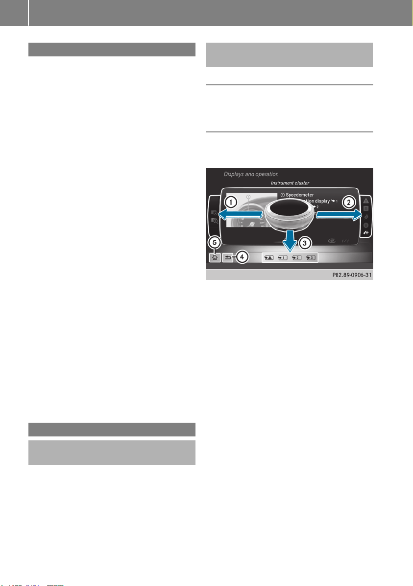
Introduction
The printed Operator's Manual provides infor-
mation about the safe operation of your vehicle.
The Digital Operator's Manual provides compre-
hensive and specifically adapted information on
your vehicle's equipment and multimedia sys-
tem. You can call up the Digital Operator's Man-
ual via the multimedia system.
i
You will not incur any costs when calling up
the Digital Operator's Manual. The Digital
Operator's Manual works without connecting
to the Internet.
There are three ways to access the topics of the
Digital Operator's Manual:
R
Visual search
The visual search allows you to explore your
vehicle "virtually". Starting from either the
vehicle exterior view or interior view, you can
access many of the different topics covered
by the Digital Operator's Manual. To access
the vehicle interior section, select the "Vehi-
cle interior" view.
R
Keyword search
The keyword search allows you to search for a
keyword by entering characters. Further
information can be found in the Digital Oper-
ator's Manual in the "Audio 20" or "COMAND"
section under the "Character entry (teleph-
ony)" keyword.
R
Contents
You can select individual sections in the con-
tents.
i
The Digital Operator's Manual is deactiva-
ted for safety reasons while driving.
Operation
Calling up the Digital Operator's Man-
ual
X
Press the Ø button on the center console.
The overview relating to the vehicle appears.
X
Select the "Operator's Manual" menu item by
turning 3 or pressing 7 the controller.
X
Confirm 7 the message about the warning
and safety notes.
The menu for the Digital Operator's Manual
appears.
Operating the Digital Operator's Man-
ual
General notes
Please observe the information about the oper-
ation of the controller (Y page 288).
Content pages
The content pages can be accessed by means of
a visual search, a keyword search or using the
contents.
X
To scroll forward/back: turn 3 the con-
troller.
X
To display in full-screen or animation: slide
8 the controller to the left :.
X
To select information text or save book-
marks: slide 9 the controller to the
right ;.
X
To select a link: slide 6 the controller
down =.
X
To exit a content page: select the %
symbol ?.
X
To call up the menu of the Digital Opera-
tor's Manual: select Þ symbol A.
26
Digital Operator's Manual

Protecting the environment
General notes
H
Environmental note
Daimler's declared policy is one of compre-
hensive environmental protection.
The objectives are for the natural resources
that form the basis of our existence on this
planet to be used sparingly and in a manner
that takes the requirements of both nature
and humanity into account.
You too can help to protect the environment
by operating your vehicle in an environmen-
tally responsible manner.
Fuel consumption and the rate of engine,
transmission, brake and tire wear are affected
by these factors:
R
operating conditions of your vehicle
R
your personal driving style
You can influence both factors. You should
bear the following in mind:
Operating conditions:
R
avoid short trips as these increase fuel con-
sumption.
R
always make sure that the tire pressures
are correct.
R
do not carry any unnecessary weight.
R
remove roof racks once you no longer need
them.
R
a regularly serviced vehicle will contribute
to environmental protection. You should
therefore adhere to the service intervals.
R
always have service work carried out at a
qualified specialist workshop.
Personal driving style:
R
do not depress the accelerator pedal when
starting the engine.
R
do not warm up the engine when the vehicle
is stationary.
R
drive carefully and maintain a safe distance
from the vehicle in front.
R
avoid frequent, sudden acceleration and
braking.
R
change gear in good time and use each gear
only up to Ô of its maximum engine speed.
R
switch off the engine in stationary traffic.
R
keep an eye on the vehicle's fuel consump-
tion.
Environmental concerns and recom-
mendations
Wherever the operating instructions require you
to dispose of materials, first try to regenerate or
re-use them. Observe the relevant environmen-
tal rules and regulations when disposing of
materials. In this way you will help to protect the
environment.
Genuine Mercedes-Benz parts
H
Environmental note
Daimler AG also supplies reconditioned major
assemblies and parts which are of the same
quality as new parts. They are covered by the
same Limited Warranty entitlements as new
parts.
!
Air bags and Emergency Tensioning Devi-
ces, as well as control units and sensors for
these restraint systems, may be installed in
the following areas of your vehicle:
R
doors
R
door pillars
R
door sills
R
seats
R
cockpit
R
instrument cluster
R
center console
Do not install accessories such as audio sys-
tems in these areas. Do not carry out repairs
or welding. You could impair the operating
efficiency of the restraint systems.
Have aftermarket accessories installed at a
qualified specialist workshop.
You could jeopardize the operating safety of
your vehicle if you use parts, tires and wheels as
well as accessories relevant to safety which
have not been approved by Mercedes-Benz. This
could lead to malfunctions in safety-relevant
Genuine Mercedes-Benz parts
27
Introduction
Z

systems, e.g. the brake system. Use only genu-
ine Mercedes-Benz parts or parts of equal qual-
ity. Only use tires, wheels and accessories that
have been specifically approved for your vehi-
cle.
Genuine Mercedes-Benz parts are subject to
strict quality control. Every part has been spe-
cifically developed, manufactured or selected
for and adapted to Mercedes-Benz vehicles.
Therefore, only genuine Mercedes-Benz parts
should be used.
More than 300,000 different genuine
Mercedes-Benz parts are available for
Mercedes-Benz models.
All authorized Mercedes-Benz Centers maintain
a supply of genuine Mercedes-Benz parts for
necessary service and repair work. In addition,
strategically located parts delivery centers pro-
vide quick and reliable parts service.
Always specify the vehicle identification number
(VIN) when ordering genuine Mercedes-Benz
parts (Y page 382).
Operator's Manual
Vehicle equipment
i
This Operator's Manual describes all models
and all standard and optional equipment of
your vehicle available at the time of going to
print. Country-specific differences are possi-
ble. Bear in mind that your vehicle may not
feature all functions described here. This also
applies to safety-relevant systems and func-
tions. The equipment in your vehicle may
therefore differ from that shown in the
descriptions and illustrations.
The original purchase contract documentation
for your vehicle contains a list of all the systems
in your vehicle.
Should you have any questions concerning
equipment and operation, please consult an
authorized Mercedes-Benz Center.
The Operator's Manual and Maintenance Book-
let are important documents and should be kept
in the vehicle.
Service and vehicle operation
Warranty
The Limited Warranty for your vehicle applies in
accordance with the warranty terms and condi-
tions in the Service and Warranty Information
booklet.
Your authorized Mercedes-Benz Center will
replace and repair all factory-installed parts in
accordance with the following warranty terms
and conditions:
R
New Vehicle Limited Warranty
R
Emission System Warranty
R
Emission Performance Warranty
R
California, Connecticut, Maine, Massachu-
setts, New York, Pennsylvania, Rhode Island
and Vermont Emission Control System War-
ranty
R
State warranty enforcement laws (lemon
laws)
Replacement parts and accessories are covered
by the Mercedes-Benz Parts and Accessories
warranties. These are available at any author-
ized Mercedes-Benz Center.
i
Should you lose your Service and Warranty
Information booklet, have an authorized
Mercedes-Benz Center arrange for a replace-
ment. The new Service and Warranty Infor-
mation booklet will be posted to you.
Information for customers in Califor-
nia
Under California law you may be entitled to a
replacement of your vehicle or a refund of the
purchase price or lease price, if after a reason-
able number of repair attempts Mercedes-Benz
USA, LLC and/or its authorized repair or service
facilities fail to fix one or more substantial
defects or malfunctions in the vehicle that are
covered by its express warranty.
During the period of 18 months from original
delivery of the vehicle or the accumulation of
18,000 miles (approximately 29,000 km) on the
odometer of the vehicle, whichever occurs first,
a reasonable number of repair attempts is pre-
sumed for a retail buyer or lessee if one or more
of the following occurs:
(1) the same substantial defect or malfunction
results in a condition that is likely to cause
28
Service and vehicle operation
Introduction

death or serious bodily injury if the vehicle is
driven, that defect or malfunction has been
subject to repair two or more times, and you
have directly notified Mercedes-Benz USA,
LLC in writing of the need for its repair.
(2) the same substantial defect or malfunction
of a less serious nature than category (1)
has been subject to repair four or more
times and you have directly notified
Mercedes-Benz in writing of the need for its
repair.
(3) the vehicle is out of service by reason of
repair of the same or different substantial
defects or malfunctions for a cumulative
total of more than 30 calendar days.
Please send your written notice to:
Mercedes-Benz USA, LLC
Customer Assistance Center
One Mercedes Drive
Montvale, NJ 07645-0350
Maintenance
USA only:
Always have the Service and Warranty Booklet
with you when you bring the vehicle to an
authorized Mercedes-Benz Center. The service
advisor will record every service for you in the
Service and Warranty Booklet.
Canada only:
Have every service in a qualified specialist work-
shop confirmed in the service report.
Roadside Assistance
The Mercedes-Benz Roadside Assistance Pro-
gram offers technical help in the event of a
breakdown. Calls to the toll-free Roadside Assis-
tance Hotline are answered by our agents 24
hours a day, 365 days a year.
1-800 FOR-MERCEDES (1-800-367-6372)
(USA)
1-800-387-0100 (Canada)
For additional information, refer to the
Mercedes-Benz Roadside Assistance Program
brochure (USA) or the "Roadside Assistance"
section in the Service and Warranty Booklet
(Canada). You will find both in the vehicle docu-
ment wallet.
Change of address or change of own-
ership
In the event of a change of address, please send
us the "Notification of Address Change" in the
Service and Warranty Booklet or simply call the
Mercedes-Benz Customer Assistance Center
(USA) at the hotline number
1-800 FOR-MERCEDES (1-800-367-6372) or
Customer Service Center (Canada) at
1-800-387-0100. This will assist us in contact-
ing you in a timely manner should the need arise.
If you sell your Mercedes, please leave all liter-
ature in the vehicle so that it is available to the
next owner.
If you have purchased a used car, please send us
the "Notification of Used Car Purchase" in the
Service and Warranty Booklet or simply call the
Mercedes-Benz Customer Assistance Center
(USA) at the hotline number
1-800 FOR-MERCEDES (1-800-367-6372) or
Customer Service (Canada) at 1-800-387-0100.
Vehicle operation outside the USA
and Canada
When you are abroad with your vehicle, observe
the following points:
R
Service facilities or replacement parts may
not be readily available.
R
Lead-free fuel for vehicles with a catalytic
converter may not be available. Leaded fuel
can cause damage to the catalytic converter.
R
The fuel may have a considerably lower
octane number. Unsuitable fuel can cause
engine damage.
Some Mercedes-Benz models are available for
delivery in Europe through our European Deliv-
ery Program. For details, consult an authorized
Mercedes-Benz Center or write to one of the
following addresses.
In the USA
Mercedes-Benz USA, LLC
European Delivery Department
One Mercedes Drive
Montvale, NJ 07645-0350
In Canada
Mercedes-Benz Canada, Inc.
European Delivery Department
98 Vanderhoof Avenue
Toronto, Ontario M4G 4C9
Service and vehicle operation
29
Introduction
Z

Sports Utility Vehicle
G
WARNING
Due to the high center of gravity, the vehicle
may start to skid and roll over in the event of
an abrupt steering maneuver and/or when
the vehicle's speed is not adapted to the road
conditions. There is a risk of an accident.
Always adapt your speed and driving style to
the vehicle's driving characteristics and to the
prevailing road and weather conditions.
Utility vehicles have a significantly higher roll-
over rate than other types of vehicles.
Failure to operate this vehicle safely may result
in an accident, rollover of the vehicle, and severe
or fatal injury.
In a rollover crash, an unbelted person is signif-
icantly more likely to die than a person wearing
a seat belt.
You and all vehicle occupants should always
wear your seat belts.
Operating safety
Important safety notes
G
WARNING
If you do not have the prescribed service/
maintenance work or any required repairs
carried out, this can result in malfunctions or
system failures. There is a risk of an accident.
Always have the prescribed service/mainte-
nance work as well as any required repairs
carried out at a qualified specialist workshop.
G
WARNING
Flammable material such as leaves, grass or
twigs may ignite if they come into contact with
hot parts of the exhaust system. There is a risk
of fire.
When driving on an unpaved road or off-road,
check the vehicle underside regularly. In par-
ticular, remove trapped plant parts or other
flammable material. Contact a qualified spe-
cialist workshop immediately if damage is
detected.
G
WARNING
Modifications to electronic components, their
software as well as wiring can impair their
function and/or the function of other net-
worked components. In particular, systems
relevant to safety could also be affected. As a
result, these may no longer function as inten-
ded and/or jeopardize the operating safety of
the vehicle. There is an increased risk of an
accident and injury.
Never tamper with the wiring as well as elec-
tronic components or their software. You
should have all work to electrical and elec-
tronic equipment carried out at a qualified
specialist workshop.
!
There is a risk of damage to the vehicle if:
R
the vehicle becomes stuck, e.g. on a high
curb or an unpaved road
R
you drive too fast over an obstacle, e.g. a
curb, a speed bump or a pothole in the road
R
a heavy object strikes the underbody or
parts of the chassis
In situations like this, the body, the under-
body, chassis parts, wheels or tires could be
damaged without the damage being visible.
Components damaged in this way can unex-
pectedly fail or, in the case of an accident, no
longer withstand the loads they are designed
to.
If the underbody paneling is damaged, com-
bustible materials such as leaves, grass or
twigs can gather between the underbody and
the underbody paneling. If these materials
come in contact with hot parts of the exhaust
system, they can catch fire.
In such situations, have the vehicle checked
and repaired immediately at a qualified spe-
cialist workshop. If on continuing your jour-
ney you notice that driving safety is impaired,
pull over and stop the vehicle immediately,
paying attention to road and traffic condi-
tions. In such cases, consult a qualified spe-
cialist workshop.
Declarations of conformity
USA: "The wireless devices of this vehicle com-
ply with Part 15 of the FCC Rules. Operation is
subject to the two following two conditions: 1)
30
Operating safety
Introduction

These devices may not cause harmful interfer-
ence, and 2) These devices must accept any
interference received, including interference
that may cause undesired operation. Changes
or modifications not expressly approved by the
party responsible for compliance could void the
user’s authority to operate the equipment."
Canada: "The wireless devices of this vehicle
comply with Industry Canada license-exempt
RSS standard(s). Operation is subject to the fol-
lowing two conditions: (1) These devices may
not cause interference, and (2) These devices
must accept any interference, including inter-
ference that may cause undesired operation of
the device."
Diagnostics connection
The diagnostics connection is only intended for
the connection of diagnostic equipment at a
qualified specialist workshop.
G
WARNING
If you connect equipment to a diagnostics
connection in the vehicle, it may affect the
operation of vehicle systems. As a result, the
operating safety of the vehicle could be affec-
ted. There is a risk of an accident.
Only connect equipment to a diagnostics con-
nection in the vehicle, which is approved for
your vehicle by Mercedes-Benz.
G
WARNING
Objects in the driver's footwell can restrict the
pedal travel or obstruct a depressed pedal.
The operating and road safety of the vehicle is
jeopardized. There is a risk of an accident.
Make sure that all objects in the vehicle are
stowed correctly, and that they cannot enter
the driver's footwell. Install the floormats
securely and as specified in order to ensure
sufficient clearance for the pedals. Do not use
loose floormats and do not place floormats on
top of one another.
!
If the engine is switched off and equipment
on the diagnostics connection is used, the
starter battery may discharge.
Connecting equipment to the diagnostics con-
nection can lead to emissions monitoring infor-
mation being reset, for example. This may lead
to the vehicle failing to meet the requirements of
the next emissions test during the main inspec-
tion.
Qualified specialist workshop
An authorized Mercedes-Benz Center is a quali-
fied specialist workshop. It has the necessary
specialist knowledge, tools and qualifications to
correctly carry out the work required on your
vehicle. This is especially the case for work rel-
evant to safety.
Always have the following work carried out at an
authorized Mercedes-Benz Center:
R
work relevant to safety
R
service and maintenance work
R
repair work
R
alterations, installation work and modifica-
tions
R
work on electronic components
Correct use
If you remove any warning stickers, you or oth-
ers could fail to recognize certain dangers.
Leave warning stickers in position.
Observe the following information when driving
your vehicle:
R
the safety notes in this manual
R
the vehicle technical data
R
traffic rules and regulations
R
laws and safety standards pertaining to motor
vehicles
Problems with your vehicle
If you should experience a problem with your
vehicle, particularly one that you believe may
affect its safe operation, we urge you to contact
an authorized Mercedes-Benz Center immedi-
ately to have the problem diagnosed and recti-
fied. If the problem is not resolved to your sat-
isfaction, please discuss the problem again with
the Mercedes-Benz Center or, if necessary, con-
tact us at one of the following addresses.
In the USA
Customer Assistance Center
Mercedes-Benz USA, LLC
Operating safety
31
Introduction
Z

3 Mercedes Drive
Montvale, NJ 07645-0350
In Canada
Customer Relations Department
Mercedes-Benz Canada, Inc.
98 Vanderhoof Avenue
Toronto, Ontario M4G 4C9
Reporting safety defects
USA only:
The following text is reproduced as required of
all manufacturers under Title 49, Code of U.S.
Federal Regulations, Part 575 pursuant to the
National Traffic and Motor Vehicle Safety Act of
1966.
If you believe that your vehicle has a defect
which could cause a crash or could cause injury
or death, you should immediately inform the
National Highway Traffic Safety Administration
(NHTSA) in addition to notifying Mercedes-Benz
USA, LLC.
If NHTSA receives similar complaints, it may
open an investigation, and if it finds that a safety
defect exists in a group of vehicles, it may order
a recall and remedy campaign. However, NHTSA
cannot become involved in individual problems
between you, your dealer, or Mercedes-Benz
USA, LLC.
To contact NHTSA, you may call the Vehicle
Safety Hotline toll-free at 1-888-327-4236
(TTY: 1-800-424-9153); go to http://
www.safercar.gov; or write to: Administrator,
NHTSA, 400 Seventh Street, SW., Washington,
DC 20590.
You can also obtain other information about
motor vehicle safety from
http://www.safercar.gov
Limited Warranty
!
Observe the notes in this Operator's Manual
regarding the correct operation of your vehi-
cle and possible damage to the vehicle. Dam-
age to the vehicle which is caused by violation
of these notes is not covered by the
Mercedes-Benz implied warranty or the new
or used-vehicle warranty.
QR code for rescue card
The QR codes are secured in the fuel filler flap
and on the opposite side on the B-pillar. In the
event of an accident, rescue services can use
the QR code to quickly find the appropriate res-
cue card for your vehicle. The current rescue
card contains the most important information
about your vehicle in a compact form, e.g. the
routing of the electric cables.
You can find more information at
www.mercedes-benz.de/qr-code.
Data stored in the vehicle
Electronic control units
There are electronic control units installed in
your vehicle. Some of these are necessary for
your vehicle to operate safely, while some offer
support during driving (driver assistance sys-
tems). In addition, your vehicle offers comfort
and entertainment functions that are also made
possible by electronic control units.
Electronic control units contain data storage
systems that can temporarily or permanently
save technical information concerning the vehi-
cle's condition, component stress and mainte-
nance requirements as well as technical events
and malfunctions.
This information generally documents the con-
dition of a component, a module, a system or the
surroundings, such as:
R
operating states of system components (e.g.
fill levels, battery status, tire pressure)
R
status messages concerning the vehicle or its
individual components (e.g. wheel rpm/
speed, deceleration, lateral acceleration, indi-
cation of whether seat belts are fastened)
R
malfunctions and defects in important system
components (e.g. lights, brakes)
R
information about events leading to vehicle
damage
R
system responses in special driving situations
(e.g. air bag deployment, intervention of sta-
bility control systems)
R
ambient conditions (e.g. temperature, rain
sensor)
In addition to performing the actual control unit
function, this data is used by manufacturers to
detect and rectify malfunctions and to optimize
vehicle functions. Most of this data is volatile
32
Data stored in the vehicle
Introduction

and processed only in the vehicle itself. Only a
small part of the data is stored in event or mal-
function memories.
When you use services, the technical data from
the vehicle can be read out by service network
employees (e.g. workshops, manufacturers) or
third parties (e.g. breakdown services). Services
can include repair services, maintenance pro-
cesses, warranty cases and quality assurance
measures. The data are read out via the con-
nection for the diagnostics connection in the
vehicle, which is required by law. The relevant
offices in the service network or third parties
collect, process and use the data. This data
documents the vehicle's technical states, is
used to help in finding malfunctions and improv-
ing quality and is sent to the manufacturer
where necessary. In addition, the manufacturer
is subject to product liability. The manufacturer
needs technical data from vehicles for this pur-
pose.
Malfunction memories in the vehicle can be
reset by a service center during repair or service
work.
You can incorporate data into the vehicle's com-
fort and infotainment functions yourself as part
of the selected equipment.
These include, for example:
R
multimedia data such as music, films or pho-
tos for playback in an integrated multimedia
system
R
address book data for use in conjunction with
an integrated hands-free system or an inte-
grated navigation system
R
navigation destinations that have been
entered
R
data about using Internet services
This data can be saved locally in the vehicle or
located on a device that you have connected to
the vehicle (e.g. smartphone, USB memory stick
or MP3 player). If this data is saved in the vehi-
cle, you can delete it at any time. This data is
sent to third parties only at your request, par-
ticularly when you use online services in accord-
ance with the settings that you have selected.
You can save and change comfort settings/
customizations in the vehicle at any time.
Depending on the equipment in question, these
can include:
R
seat and steering wheel position settings
R
suspension and climate control settings
R
custom settings such as interior lighting
If your vehicle is equipped appropriately, you
can connect your smartphone or another mobile
end device to the vehicle. You can control this by
means of the control elements integrated in the
vehicle. The smartphone's picture and sound
can be output via the multimedia system. Spe-
cific items of information are also sent to your
smartphone.
Depending on the type of integration, this can
include:
R
general vehicle information
R
position data
This allows the use of selected smartphone
apps, such as navigation or music player apps.
There is no additional interaction between the
smartphone and the vehicle, particularly active
access to vehicle data. The type of additional
data processing is determined by the provider of
the app being used. Whether you can configure
settings for it and, if so, which ones, depends on
the app and your smartphone's operating sys-
tem.
Online services
Wireless network connection
If your vehicle has a wireless network connec-
tion, data can be exchanged between your vehi-
cle and other systems. The wireless network
connection is made possible by the vehicle's
own transmitter and receiver or by mobile devi-
ces that you have brought into the vehicle (e.g.
smartphones). Online functions can be used via
this wireless network connection. These include
online services and applications/apps provided
by the manufacturer or other providers.
Services provided by the manufacturer
In the case of the manufacturer's online serv-
ices, the manufacturer describes the functions
in a suitable place (e.g. operating instructions,
manufacturer's website) and provides the asso-
ciated information subject to data protection
legislation. Personal data can be used in order to
provide online services. The exchange of data
for this purpose takes place via a secure con-
nection, e.g. with the manufacturer's IT systems
intended for the purpose. Collecting, processing
and using personal data beyond the provision of
services is permitted only on the basis of a stat-
utory permit or declaration of consent.
Data stored in the vehicle
33
Introduction
Z

You can usually activate and deactivate the serv-
ices and functions (sometimes subject to a fee).
In many cases, this also applies to the vehicle's
entire data connection. However, this does not
apply in particular to legally prescribed func-
tions and services such as the "eCall" emer-
gency call system.
Services from third parties
If it is possible to use online services from other
providers, these services are the responsibility
of the provider in question and subject to that
provider's data protection conditions and terms
of use. The manufacturer has no influence over
the content exchanged here.
For this reason, please ask the service provider
for information about the type, extent and pur-
pose of the collection and use of personal data
when services are provided by third parties.
COMAND/mbrace
If the vehicle is equipped with COMAND or
mbrace, additional data about the vehicle's
operation, the use of the vehicle in certain sit-
uations, and the location of the vehicle may be
compiled through COMAND or the mbrace sys-
tem.
For additional information please refer to the
COMAND User Manual or the Digital Operator's
Manual and/or the mbrace Terms and Condi-
tions.
Event data recorders
This vehicle is equipped with an event data
recorder (EDR). This vehicle is equipped with an
event data recorder (EDR). The main purpose of
an EDR is to record, in certain crash or near
crash-like situations, such as an air bag deploy-
ment or hitting a road obstacle, data that will
assist in understanding how a vehicle's systems
performed. The EDR is designed to record data
relating to vehicle dynamics and safety systems
for a short period of time, typically 30 seconds
or less.
The EDR in this vehicle is designed to record
such data as:
R
How various systems in your vehicle were
operating
R
Whether or not the driver and passenger
safety belts were buckled/fastened
R
How far (if at all) the driver was depressing the
accelerator and/or brake pedal and
R
How fast the vehicle was traveling
These data can help provide a better under-
standing of the circumstances in which crashes
and injuries occur. NOTE: EDR data are recor-
ded by your vehicle only if a non-trivial crash
situation occurs; no data are recorded by the
EDR under normal driving conditions and no
personal data (e.g. name, gender, age and crash
location) are recorded. However, other parties,
such as law enforcement could combine the
EDR data with the type of personally identifying
data routinely acquired during a crash investi-
gation.
Access to the vehicle and/or the EDR is needed
to read data that is recorded by an EDR, and
special equipment is required. In addition to the
vehicle manufacturer, other parties that have
the special equipment, such as law enforce-
ment, can read the information by accessing the
vehicle or the EDR.
EDR data may be used in civil and criminal mat-
ters as a tool in accident reconstruction, acci-
dent claims and vehicle safety. Since the Crash
Data Retrieval CDR tool that is used to extract
data from the EDR is commercially available,
Mercedes-Benz USA, LLC ("MBUSA") expressly
disclaims any and all liability arising from the
extraction of this information by unauthorized
Mercedes-Benz personnel.
MBUSA will not share EDR data with others
without the consent of the vehicle owners or, if
the vehicle is leased, without the consent of the
lessee. Exceptions to this representation
include responses to subpoenas by law enforce-
ment; by federal, state or local government; in
connection with or arising out of litigation involv-
ing MBUSA or its subsidiaries and affiliates; or,
as required by law.
Warning: The EDR is a component of the
Restraint System Module. Tampering with, alter-
ing, modifying or removing the EDR component
may result in a malfunction of the Restraint Sys-
tem Module and other systems.
State laws or regulations regarding EDRs that
conflict with federal regulation are pre-empted.
34
Data stored in the vehicle
Introduction

This means that in the event of such conflict, the
federal regulation governs. As of February 2013,
13 states have enacted laws relating to EDRs.
Information on copyright
Free and open-source software
Information on license for free and open-source
software used in your vehicle can be found on
the data carrier in your vehicle document wallet
and, including updates, on the following web-
site:
http://www.mercedes-benz.com/
opensource
Information on copyright
35
Introduction
Z
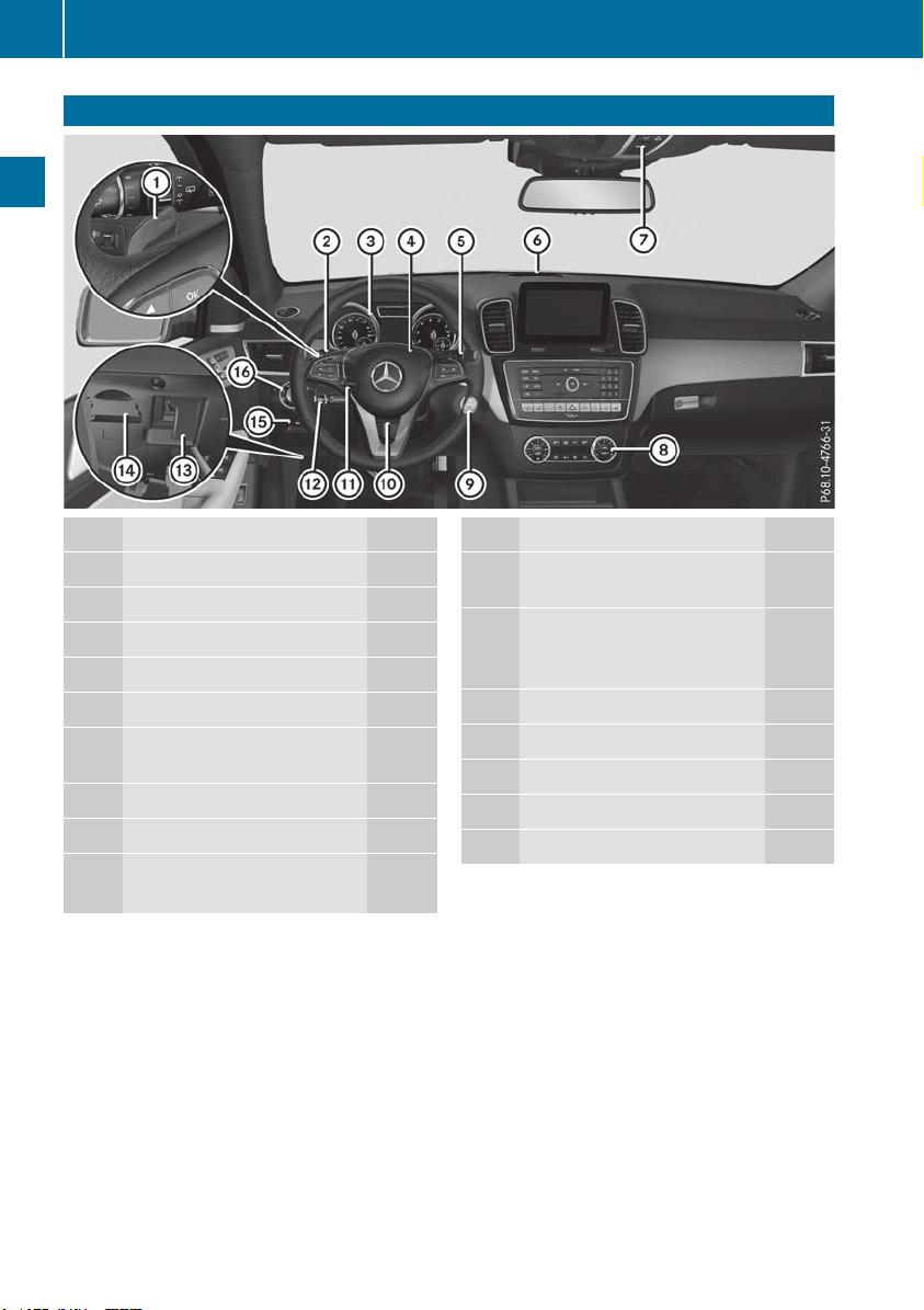
Cockpit
Function Page
:
Steering wheel paddle shifter 147
;
Combination switch 111
=
Instrument cluster 37
?
Horn
A
DIRECT SELECT lever 143
B
Parking Assist PARKTRONIC
warning display 189
C
Overhead control panel 42
D
Climate control systems 122
E
Ignition lock 135
Start/Stop button 135
Function Page
F
Adjusts the steering wheel
manually 103
G
Adjusts the steering wheel
electrically 103
Steering wheel heating 104
H
Cruise control lever 170
I
Opens the hood 321
J
Diagnostics connection 31
K
Electric parking brake 157
L
Light switch 110
36
Cockpit
At a glance
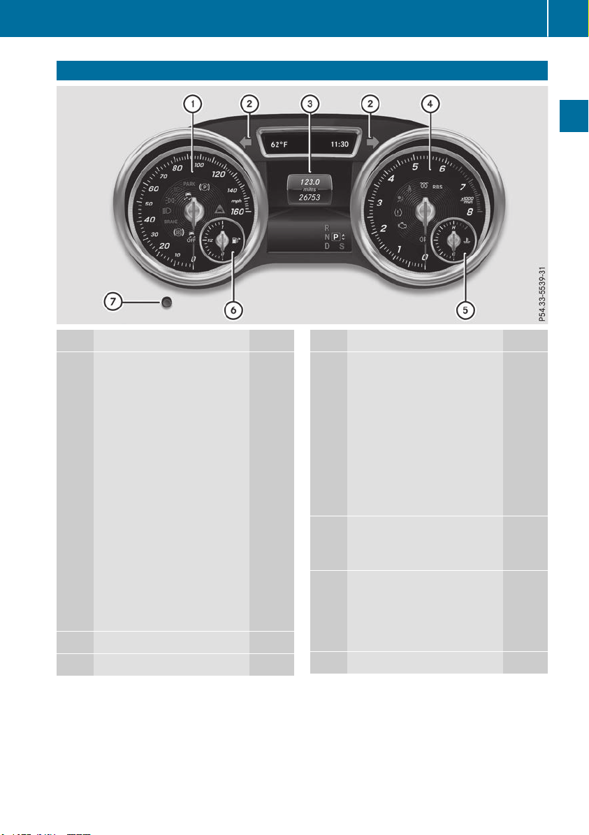
Instrument cluster
Function Page
:
Speedometer with segments 229
Warning and indicator lamps:
å ESP
®
OFF
279
! ABS
277
Brakes 276
$ (USA only)
J (Canada only)
L Low-beam headlamps
111
T Parking lamps
111
÷ ESP
®
279
K High-beam headlamps
111
Electric parking brake (red) 282
F (USA only)
! (Canada only)
! Electric parking brake
(yellow)
282
· Distance warning
285
;
#! Turn signals
111
=
Multifunction display 231
Function Page
?
Tachometer 229
Warning and indicator lamps:
R Rear fog lamp
111
; Check Engine
283
h Tire pressure monitor
286
6 Restraint system
45
ü Seat belts
274
% Diesel engine: preglow
137
é RBS (Recuperative
Brake System)
A
Coolant temperature gauge 230
Warning and indicator lamps:
? Coolant
283
B
Fuel level indicator
Warning and indicator lamps:
8 Reserve fuel with fuel
filler flap location indicator
(right-hand side) 283
C
Instrument cluster lighting 229
i
Information on displaying the outside tem-
perature in the multifunction display can be
found under "Outside temperature display"
(Y page 229).
Instrument cluster
37
At a glance
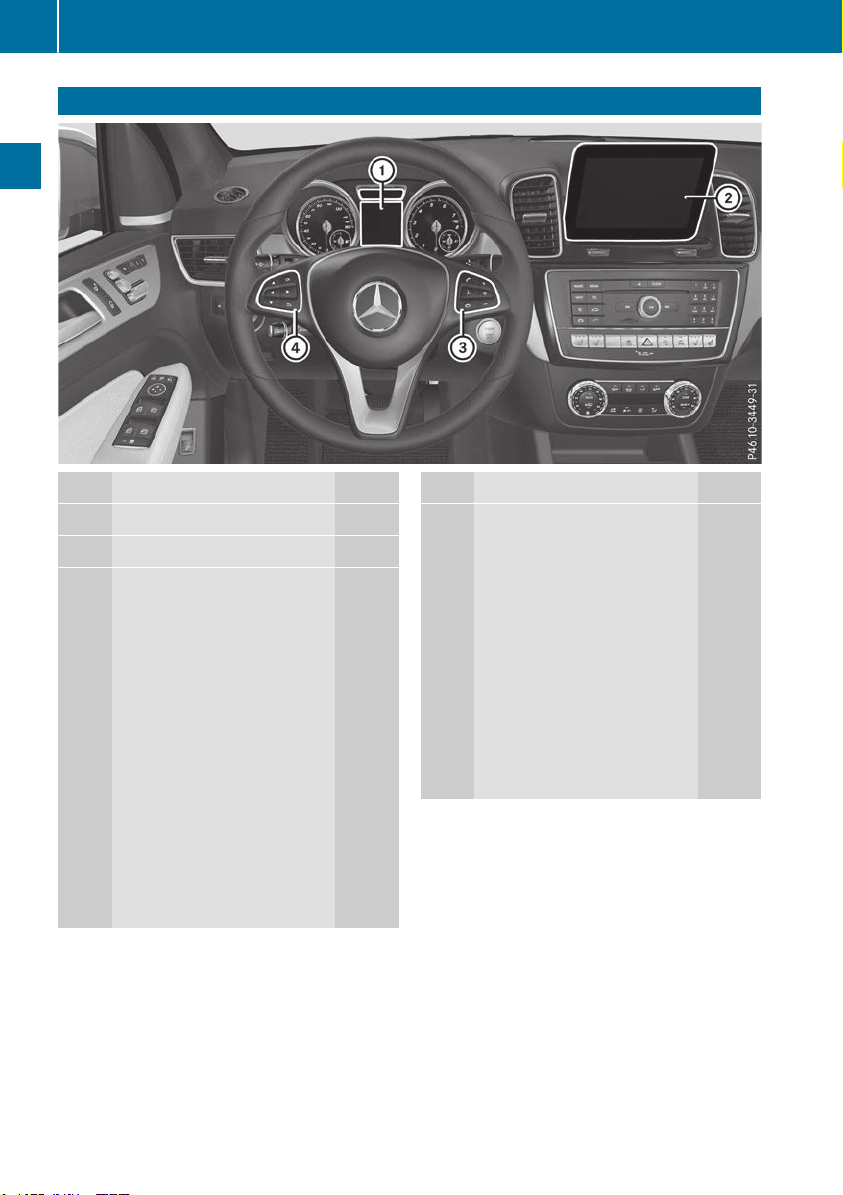
Multifunction steering wheel
Function Page
:
Multifunction display 231
;
Multimedia system display
= ?
Switches on voice-operated
navigation or the Voice Con-
trol System
8
Mute
WX
Adjusts the volume
~
Rejects or ends a call 236
Exits phone book/redial
memory
6
Makes or accepts a call
Switches to the redial mem-
ory
Function Page
?
=;
Selects a menu 230
9:
Selects a submenu or scrolls
through lists 230
a
Confirms a selection 230
Hides display messages 244
%
Back 230
Switches off voice-operated
navigation or the Voice Con-
trol System
i In vehicles with multimedia system
COMAND you can find further information:
R
on the multimedia system in the Digital
Operator's Manual
R
on the DVD changer or single DVD drive in
the Digital Operator's Manual
R
on the Voice Control System in the sepa-
rate operating instructions
i In vehicles with multimedia system Audio 20
you can find further information:
R
on the multimedia system in the Digital
Operator's Manual
R
on the voice-operated control of the navi-
gation in the manufacturer's operating
instructions
38
Multifunction steering wheel
At a glance
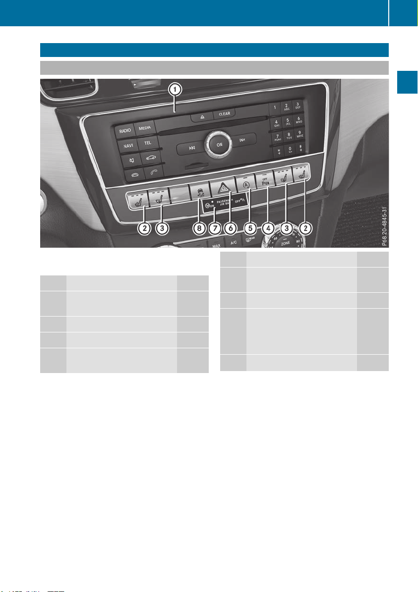
Center console
Center console, upper section
i
Vehicles with the Off-Road Engineering
package
Function Page
:
Multimedia system; see the
Digital Operator's Manual
;
c Seat heating
101
=
s Seat ventilation
102
?
c Parking Assist
PARKTRONIC 188
Function Page
A
è ECO start/stop func-
tion
139
B
£ Hazard warning lamps
112
C
PASSENGER AIRBAG indica-
tor lamps 45
Anti-theft alarm system indi-
cator lamp 75
D
å ESP
®
70
Center console
39
At a glance
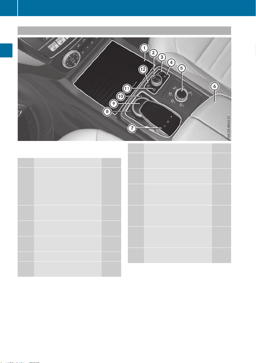
Center console, lower section
i
Vehicles with the Off-Road Engineering
package
Function Page
:
Stowage compartment 297
Cup holder 304
Ashtray 307
Cigarette lighter 307
Socket 308
;
Selector wheel for level con-
trol 179
=
à DSR (Downhill Speed
Regulation)
214
?
r Manual gearshifting
(permanent setting) 147
A
DYNAMIC SELECT controller 142
B
Stowage compartment with
Media Interface 296
Function Page
C
Touchpad; see Digital Opera-
tor's Manual
D
% Back button (see the
Digital Operator's Manual)
E
Multimedia system control-
ler; see Digital Operator's
Manual
F
g Switches to the favor-
ites button (see the Digital
Operator's Manual)
G
Switches to the vehicle set-
tings display (see the Digital
Operator's Manual)
H
+ LOW RANGE off-road
gear 217
40
Center console
At a glance
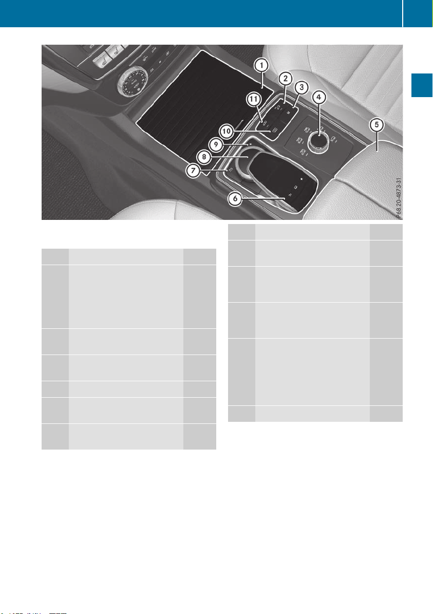
i
Vehicles with the AIRMATIC package and
Mercedes-AMG vehicles
Function Page
:
Stowage compartment 297
Cup holder 304
Ashtray 307
Cigarette lighter 307
Socket 308
;
à DSR (Downhill Speed
Regulation)
214
=
r Manual gearshifting
(permanent setting) 147
?
DYNAMIC SELECT controller 142
A
Stowage compartment with
Media Interface 296
B
Touchpad; see Digital Opera-
tor's Manual
Function Page
C
% Back button (see the
Digital Operator's Manual)
D
Multimedia system control-
ler; see Digital Operator's
Manual
E
g Switches to the favor-
ites button (see the Digital
Operator's Manual)
F
Switches to the vehicle set-
tings display (see the Digital
Operator's Manual)
AMG adaptive sport suspen-
sion system (Mercedes-AMG
vehicles) 187
G
Á Level control
185
Center console
41
At a glance
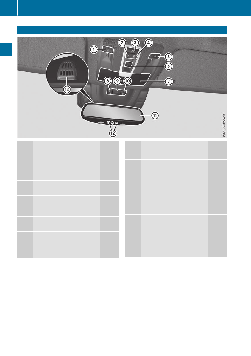
Overhead control panel
Function Page
:
p Switches the left-hand
reading lamp on/off
114
;
c Switches the front inte-
rior lighting on 114
=
u Switches the rear inte-
rior lighting on or off 114
?
| Switches the front inte-
rior lighting/automatic inte-
rior lighting control off
114
A
p Switches the right-
hand reading lamp on/off 114
B
3 Opens/closes the pan-
orama roof with power tilt/
sliding panel and roller sun-
blinds 94
Function Page
C
Eyeglasses compartment 297
D
F Breakdown assistance
call button (mbrace system)
311
E
G SOS button (mbrace
system) 310
F
ï Info call button
(mbrace system) 312
G
Rear-view mirror 105
H
Buttons for the garage door
opener 319
I
Microphone for mbrace
(emergency call system),
telephone and the Voice
Control System
1
1
The Voice Control System is only available in combination with COMAND. Please observe the separate oper-
ating instructions.
42
Overhead control panel
At a glance
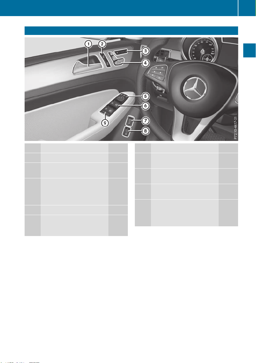
Door control panel
Function Page
:
Opens the door 83
;
%&Unlocks/locks
the vehicle
83
=
r 45=
Stores settings for the seat,
exterior mirrors and steering
column (memory function) 108
?
Adjusts the seats 97
A
7Zö\
Adjusts and folds the exterior
mirrors in/out electrically 105
Function Page
B
W Opens/closes the side
windows
89
C
q Opens/closes the tail-
gate 87
D
6 Plug-in hybrid: Unlocks
the fuel filler flap
E
n Activates/deactivates
the override feature for the
side windows in the rear
compartment
65
Door control panel
43
At a glance
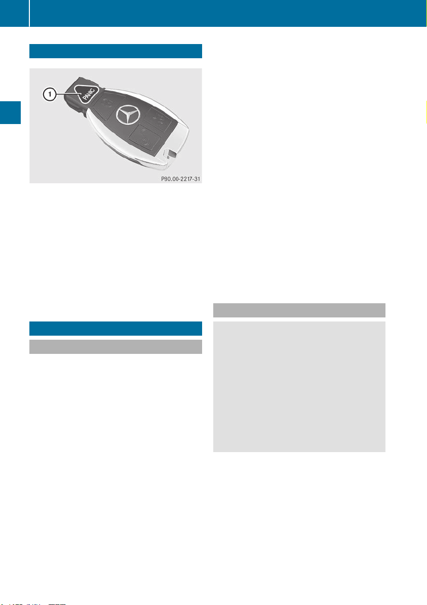
Panic alarm
X
To activate: press ! button : for
approximately one second.
A visual and audible alarm is triggered if the
alarm system is armed.
X
To deactivate: press ! button : again.
or
X
Insert the SmartKey into the ignition lock.
or, on vehicles with KEYLESS‑GO:
X
Press the Start/Stop button.
The SmartKey must be in the vehicle.
Occupant safety
Introduction to the restraint system
The restraint system can reduce the risk of vehi-
cle occupants coming into contact with parts of
the vehicle's interior in the event of an accident.
The restraint system can also reduce the forces
to which vehicle occupants are subjected during
an accident.
The restraint system comprises:
R
Seat belt system
R
Air bags
R
Child restraint system
R
Child seat securing systems
The components of the restraint system work in
conjunction with each other. They can only
deploy their protective function if, at all times, all
vehicle occupants:
R
have fastened their seat belts correctly
(Y page 47)
R
have the seat and head restraint adjusted
properly (Y page 97)
As the driver, you also have to make sure that
the steering wheel is adjusted correctly.
Observe the information relating to the correct
driver's seat position (Y page 97).
You also have to make sure that an air bag can
inflate properly if deployed (Y page 49).
An air bag supplements a correctly worn seat
belt. As an additional safety device, the air bag
increases the level of protection for vehicle
occupants in the event of an accident. For exam-
ple, if, in the event of an accident, the protection
offered by the seat belt is sufficient, the air bags
are not deployed. When an accident occurs, only
the air bags that increase protection in that par-
ticular accident situation are deployed. How-
ever, seat belts and air bags generally do not
protect against objects penetrating the vehicle
from the outside.
Information on restraint system operation can
be found under "Triggering of the Emergency
Tensioning Devices and air bags" (Y page 56).
See "Children in the vehicle" for information on
children traveling with you in the vehicle as well
as on child restraint systems (Y page 59).
Important safety notes
G
WARNING
Modifications to the restraint system may
cause it to no longer work as intended. The
restraint system may then not perform its
intended protective function and may fail in an
accident or trigger unexpectedly, for example.
This poses an increased risk of injury or even
fatal injury.
Never modify parts of the restraint system.
Never tamper with the wiring, the electronic
components or their software.
If it is necessary to modify components of the
restraint system to accommodate a person with
disabilities, contact an authorized Mercedes-
Benz Center for details. USA only: for further
information contact our Customer Assistance
Center at 1-800 FOR-MERCEDES
(1‑800‑367‑6372).
Mercedes-Benz recommends that you only use
driving aids which have been approved specifi-
cally for your vehicle by Mercedes-Benz.
44
Occupant safety
Safety
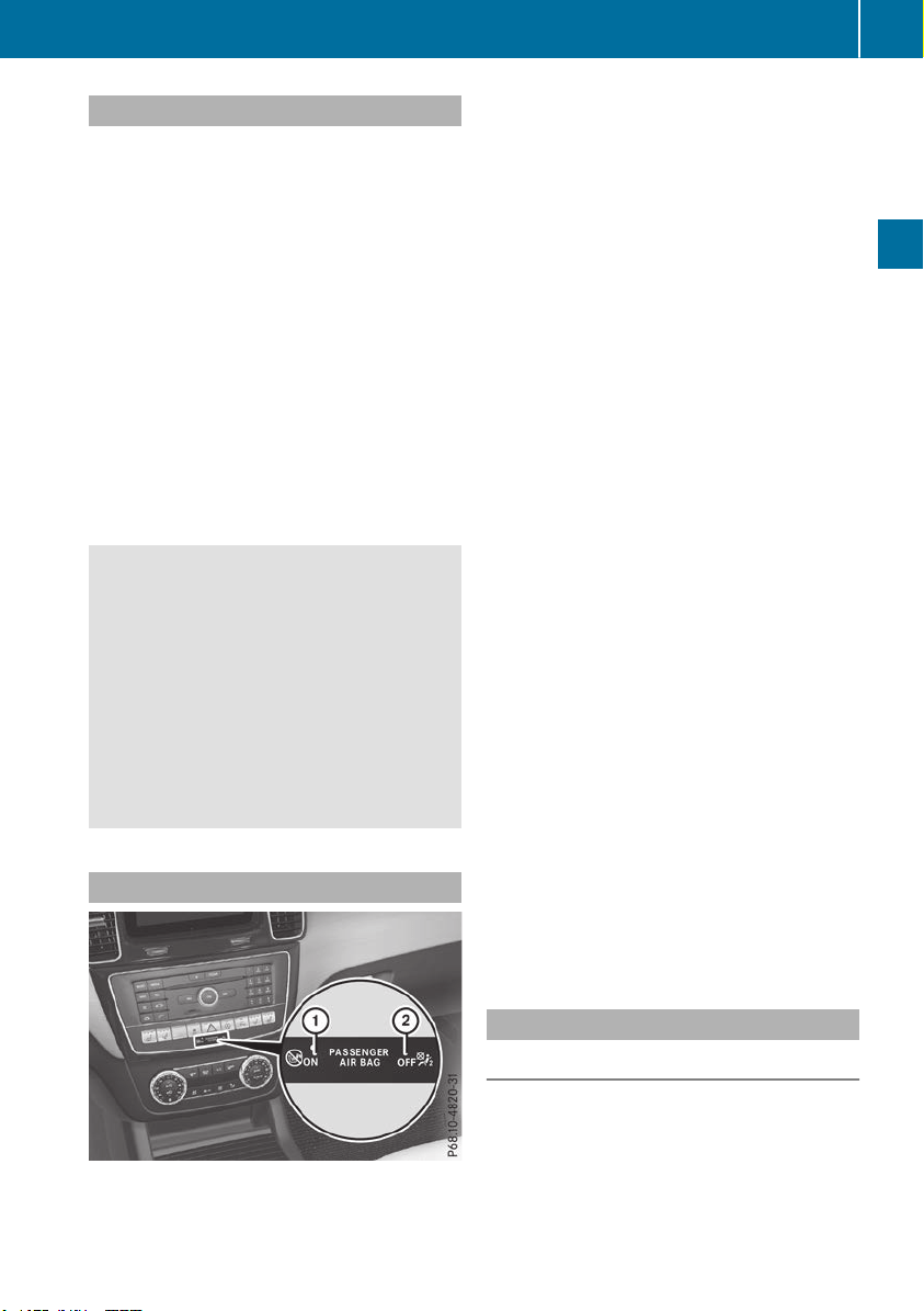
Restraint system warning lamp
The functions of the restraint system are
checked after the ignition is switched on and at
regular intervals while the engine is running.
Therefore, malfunctions can be detected in
good time.
The 6 restraint system warning lamp on the
instrument cluster lights up when the ignition is
switched on. It goes out no later than a few sec-
onds after the vehicle is started. The compo-
nents of the restraint system are in operational
readiness.
A malfunction has occurred if the 6 restraint
system warning lamp:
R
does not light up after the ignition is switched
on
R
does not go out after a few seconds with the
engine running
R
lights up again while the engine is running
G
WARNING
If the restraint system is malfunctioning,
restraint system components may be trig-
gered unintentionally or may not deploy as
intended during an accident. This can affect
for example the Emergency Tensioning
Device or the air bag. This poses an increased
risk of injury or even fatal injury.
Have the restraint system checked and
repaired in a qualified specialist workshop as
soon as possible.
PASSENGER AIR BAG indicator lamp
PASSENGER AIR BAG ON indicator lamp : and
PASSENGER AIR BAG OFF indicator lamp ; are
part of the Occupant Classification System
(OCS).
The indicator lamps display the status of the
front-passenger front air bag.
R
PASSENGER AIR BAG ON lights up for 60 sec-
onds, subsequently both indicator lamps are
off (PASSENGER AIR BAG ON and OFF): the
front-passenger front air bag is able to deploy
in the event of an accident.
R
PASSENGER AIR BAG OFF lights up: the front-
passenger front air bag is deactivated. It will
then not be deployed in the event of an acci-
dent.
If the PASSENGER AIR BAG ON indicator lamp is
off, only the PASSENGER AIR BAG OFF indicator
lamp shows the status of the front-passenger
front air bag. The PASSENGER AIR BAG OFF
indicator lamp may be lit continuously or be off.
Depending on the person in the front-passenger
seat, the front-passenger front air bag must
either be deactivated or enabled; see the fol-
lowing points. You must make sure of this both
before and during a journey.
R
Children in a child restraint system:
whether the front-passenger front air bag is
enabled or deactivated depends on the instal-
led child restraint system, and the age and
size of the child. Therefore, be sure to observe
the notes on the "Occupant Classification
System (OCS)" (Y page 51) and on "Chil-
dren in the vehicle" (Y page 59). There you
will also find instructions on rearward and
forward-facing child restraint systems on the
front-passenger seat.
R
All other persons: depending on the classi-
fication of the person in the front-passenger
seat, the front-passenger front air bag is ena-
bled or deactivated (Y page 51). Be sure to
observe the notes on "Seat
belts“ (Y page 45) and "Air bags"
(Y page 49). There you can also find infor-
mation on the correct seat position.
Seat belts
Introduction
Seat belts are the most effective means of
restricting the movement of vehicle occupants
in the event of an accident or the vehicle rolling
over. This reduces the risk of vehicle occupants
coming into contact with parts of the vehicle
interior or being ejected from the vehicle. Fur-
thermore, the seat belt helps to keep the vehicle
Occupant safety
45
Safety
Z

occupant in the best position in relation to the
air bag.
The seat belt system comprises:
R
Seat belts
R
Emergency Tensioning Devices for the front
seat belts and the outer seat belts in the rear
R
Seat belt force limiters
If the seat belt is pulled out of the belt outlet
quickly or with a jerky movement, the belt
retractor locks. The belt strap cannot be extrac-
ted any further.
The Emergency Tensioning Device tightens the
seat belt in an accident, pulling the belt close
against the body. However it does not pull the
vehicle occupant back in the direction of the
backrest.
The Emergency Tensioning Device does not cor-
rect an incorrect seat position or the routing of
an incorrectly fastened seat belt.
When triggered, a seat belt force limiter helps to
reduce the force exerted by the seat belt on the
vehicle occupant.
The seat belt force limiters for the front seats are
synchronized with the front air bags, which
absorb part of the deceleration force. This can
reduce the force exerted on the vehicle occu-
pants during an accident.
!
If the front-passenger seat is not occupied,
do not engage the seat belt tongue in the
buckle on the front-passenger seat. Other-
wise, in addition to other systems, the Emer-
gency Tensioning Device could also be trig-
gered in the event of an accident and would
need to be replaced.
Important safety notes
The use of seat belts and child restraint systems
is required by law in:
R
all 50 states
R
the U.S. territories
R
the District of Columbia
R
all Canadian provinces
Even where this is not required by law, all vehicle
occupants should correctly fasten their seat
belts before starting the journey.
G
WARNING
If the seat belt is not worn correctly, it cannot
perform its intended protective function. An
incorrectly fastened seat belt can also cause
injuries, for example, in the event of an acci-
dent or when braking or changing direction
abruptly. This poses an increased risk of injury
or even fatal injury.
Always ensure that all vehicle occupants have
their seat belts fastened correctly and are sit-
ting properly.
The components of the restraint system work in
conjunction with each other. They can only
deploy their protective function if, at all times, all
vehicle occupants:
R
have fastened their seat belts correctly
(Y page 47)
R
have the seat and head restraint adjusted
properly (Y page 97)
G
WARNING
The seat belt does not offer the intended level
of protection if you have not moved the back-
rest to an almost vertical position. When brak-
ing or in the event of an accident, you could
slide underneath the seat belt and sustain
abdomen or neck injuries, for example. This
poses an increased risk of injury or even fatal
injury.
Adjust the seat properly before beginning
your journey. Always ensure that the backrest
is in an almost vertical position and that the
shoulder section of your seat belt is routed
across the center of your shoulder.
G
WARNING
Persons less than 5 ft (1.50 m) tall cannot
wear the seat belt correctly without an addi-
tional and suitable restraint system. If the
seat belt is not worn correctly, it cannot per-
form its intended protective function. An
incorrectly fastened seat belt can also cause
injuries, for example, in the event of an acci-
dent or when braking or changing direction
abruptly. This poses an increased risk of injury
or even fatal injury.
For this reason, always secure persons under
5 ft (1.50 m) tall in suitable additional restraint
systems.
46
Occupant safety
Safety

If a child younger than twelve years old and
under 5 ft (1.50 m) in height is traveling in the
vehicle:
R
always secure the child in a child restraint
system suitable for this Mercedes-Benz vehi-
cle. The child restraint system must be appro-
priate to the age, weight and size of the child.
R
always observe the instructions and safety
notes on "Children in the vehicle"
(Y page 59) in addition to the child restraint
system manufacturer's installation and oper-
ating instructions
R
always observe the instructions and safety
notes on the "Occupant classification system
(OCS)". (Y page 51)
G
WARNING
The seat belts may not perform their intended
protective function if:
R
they are damaged, modified, extremely
dirty, bleached or dyed
R
the seat belt buckle is damaged or
extremely dirty
R
the Emergency Tensioning Devices, belt
anchorages or inertia reels have been modi-
fied.
Seat belts may be damaged in an accident,
although the damage may not be visible, e.g.
due to splinters of glass. Modified or damaged
seat belts may tear or fail, e.g. in an accident.
Modified Emergency Tensioning Devices
could accidentally trigger or fail to deploy
when necessary. This poses an increased risk
of injury or even fatal injury.
Never modify the seat belts, Emergency Ten-
sioning Devices, belt anchorages and inertia
reels. Make sure that the seat belts are
undamaged, not worn out and clean. Follow-
ing an accident, have the seat belts checked
immediately at a qualified specialist work-
shop.
Only use seat belts that have been approved for
your vehicle by Mercedes-Benz.
Proper use of the seat belts
Observe the safety notes on the seat belt
(Y page 46).
All vehicle occupants must be wearing the seat
belt correctly before beginning the journey. Also
make sure that all vehicle occupants are always
wearing the seat belt correctly while the vehicle
is in motion.
When fastening the seat belt, always make sure
that:
R
the seat belt buckle tongue is inserted only
into the belt buckle belonging to that seat
R
the seat belt is pulled tight across your body
Avoid wearing bulky clothing, e.g. a winter
coat.
R
the seat belt is not twisted
Only then can the forces which occur be dis-
tributed over the area of the belt.
R
the shoulder section of the belt is routed
across the center of your shoulder
The shoulder section of the seat belt should
not touch your neck or be routed under your
arm or behind your back. Where possible,
adjust the seat belt to the appropriate height.
R
the lap belt is taut and passes across your lap
as low down as possible
The lap belt must always be routed across
your hip joints and not across your abdomen.
This applies particularly to pregnant women.
If necessary, push the lap belt down to your
hip joint and pull it tight using the shoulder
section of the belt.
R
the seat belt is not routed across sharp, poin-
ted or fragile objects
If you have such items located on or in your
clothing, e.g. pens, keys or eyeglasses, store
these in a suitable place.
R
only one person is using a seat belt
Infants and children must never travel sitting
on the lap of a vehicle occupant. In the event
of an accident, they could be crushed
between the vehicle occupant and seat belt.
R
objects are never secured with a seat belt if
the seat belt is also being used by one of the
vehicle's occupants
Also ensure that there are never objects
between a person and the seat, e.g. cushions.
Seat belts are only intended to secure and
restrain vehicle occupants. Always observe the
"Loading guidelines" for securing objects, lug-
gage or loads (Y page 295).
Occupant safety
47
Safety
Z
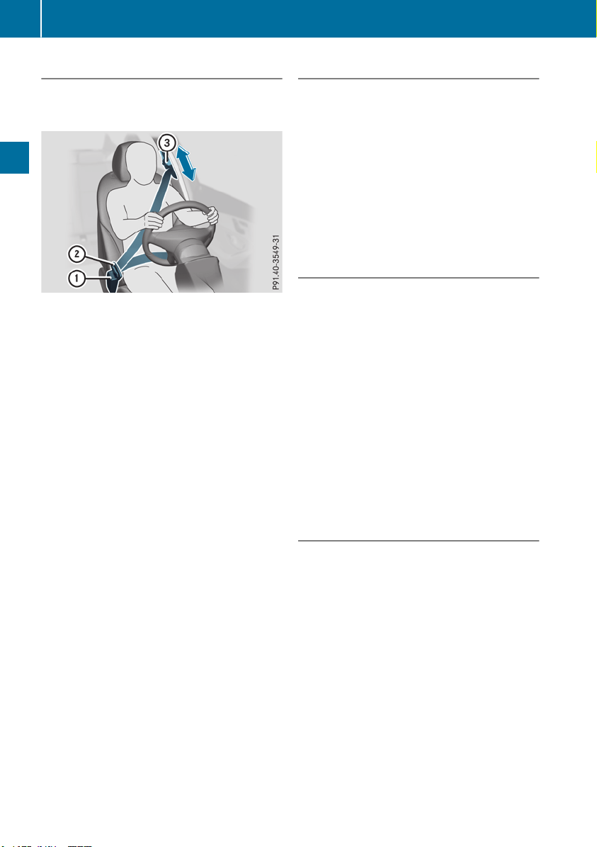
Fastening and adjusting the seat belts
Observe the safety notes on the seat belt
(Y page 46) and the notes on correct use of seat
belts (Y page 47).
Basic illustration
X
Adjust the seat (Y page 97).
The seat backrest must be in an almost
upright position.
X
Pull the seat belt smoothly from the belt outlet
and engage belt tongue ; into belt
buckle :.
The seat belt on the driver’s seat and the
front-passenger seat may be tightened auto-
matically, see "Belt adjustment"
(Y page 48).
X
If necessary, pull up on the shoulder section
of the seat belt to tighten the belt across your
body.
The shoulder section of the seat belt must
always be routed across the center of the shoul-
der. Adjust the belt outlet if necessary.
X
To raise: slide the belt outlet up.
The belt outlet will engage in various posi-
tions.
X
To lower: hold belt outlet release = and slide
the belt outlet down.
X
Let go of belt outlet release = in the desired
position and make sure that the belt outlet
engages.
All seat belts except the driver's seat belt are
equipped with a special seat belt retractor to
securely fasten child restraint systems in the
vehicle. Further information can be found under
"Special seat belt retractor" (Y page 60).
Releasing seat belts
!
Make sure that the seat belt is fully rolled up.
Otherwise, the seat belt or belt tongue will be
trapped in the door or in the seat mechanism.
This could damage the door, the door trim
panel and the seat belt. Damaged seat belts
can no longer fulfill their protective function
and must be replaced. Visit a qualified spe-
cialist workshop.
X
Press the release button in the belt buckle,
hold the belt tongue firmly and guide the belt
back.
Seat belt adjustment
The belt adjustment is a convenience function
integrated into PRE-SAFE
®
. With this function,
the driver's and front-passenger seat belts are
adjusted to the upper body of the vehicle occu-
pant.
The seat belt strap will slightly tighten if:
R
the belt tongue is inserted into the buckle and
R
the ignition is switched on
The seat belt adjustment will apply a certain
tightening force if any slack is detected between
the vehicle occupant and the seat belt. Do not
grab hold of the seat belt.
The belt adjustment can be switched on and off
using the on-board computer (Y page 240).
Belt warning for the driver and front
passenger
The 7 seat belt warning lamp in the instru-
ment cluster is a reminder that all vehicle occu-
pants must wear their seat belts. It may light up
continuously or flash. In addition, there may be
a warning tone.
Regardless of whether the driver's seat belt has
already been fastened, the 7 seat belt warn-
ing lamp lights up for six seconds each time the
engine is started. If the front doors are closed
and the driver's or front-passenger seat belt has
not been fastened, the 7 seat belt warning
lamp lights up again after the six seconds. As
soon as the driver's and front-passenger seat
belts are fastened or a front door is opened
again, the 7 seat belt warning lamp goes out.
If the driver's seat belt is not fastened after the
engine is started, an additional warning tone will
sound. The warning tone switches off after six
48
Occupant safety
Safety

seconds or once the driver's seat belt is fas-
tened.
If the vehicle's speed exceeds 15 mph
(25 km/h) once and the driver's and front-
passenger seat belts are not fastened, a warning
tone sounds. A warning tone also sounds with
increasing intensity for 60 seconds or until the
driver or front passenger have fastened their
seat belts.
If the driver or front passenger unfasten their
seat belts during the journey, the seat belt warn-
ing is activated again.
Air bags
Introduction
The installation point of an air bag can be rec-
ognized by the AIRBAG marking.
An air bag complements the correctly fastened
seat belt. It is no substitute for the seat belt. The
air bag provides additional protection in appli-
cable accident situations.
Not all air bags are deployed in an accident. The
different air bag systems function independ-
ently from one another (Y page 56).
However, no system available today can com-
pletely eliminate injuries and fatalities.
It is also not possible to rule out a risk of injury
caused by an air bag due to the high speed at
which the air bag must be deployed.
Important safety notes
G
WARNING
If you do not sit in the correct seat position,
the air bag cannot protect as intended and
could even cause additional injury when
deployed. This poses an increased risk of
injury or even fatal injury.
To avoid hazardous situations, always make
sure that all of the vehicle's occupants:
R
have fastened their seat belts correctly,
including pregnant women
R
are sitting correctly and maintain the great-
est possible distance to the air bags
R
follow the following instructions
Always make sure that there are no objects
between the air bag and the vehicle's occu-
pants.
R
Adjust the seats properly before beginning
your journey. Always make sure that the seat
is in an almost upright position. The center of
the head restraint must support the head at
about eye level.
R
Move the driver's and front-passenger seats
as far back as possible. The driver's seat posi-
tion must allow the vehicle to be driven safely.
R
Only hold the steering wheel on the outside.
This allows the air bag to be fully deployed.
R
Always lean against the backrest while driv-
ing. Do not lean forward or lean against the
door or side window. You may otherwise be in
the deployment area of the air bags.
R
Always keep your feet in the footwell in front
of the seat. Do not put your feet on the dash-
board, for example. Your feet may otherwise
be in the deployment area of the air bag.
R
For this reason, always secure persons less
than 5 ft (1.50 m) tall in suitable restraint sys-
tems. Up to this height, the seat belt cannot
be worn correctly.
If a child is traveling in your vehicle, also
observe the following notes:
R
Always secure children under twelve years of
age and less than 5 ft (1.50 m) tall in suitable
child restraint systems.
R
Child restraint systems should be installed on
the rear seats.
R
Only secure a child in a rearward-facing child
restraint system on the front-passenger seat
when the front-passenger front air bag is
deactivated. If the PASSENGER AIR BAG OFF
indicator lamp is permanently lit, the front-
passenger front air bag is deactivated
(Y page 45).
R
Always observe the instructions and safety
notes on the "Occupant Classification System
(OCS)" (Y page 51) and on "Children in the
vehicle" (Y page 59) in addition to the child
restraint system manufacturer's installation
and operating instructions.
Occupant safety
49
Safety
Z
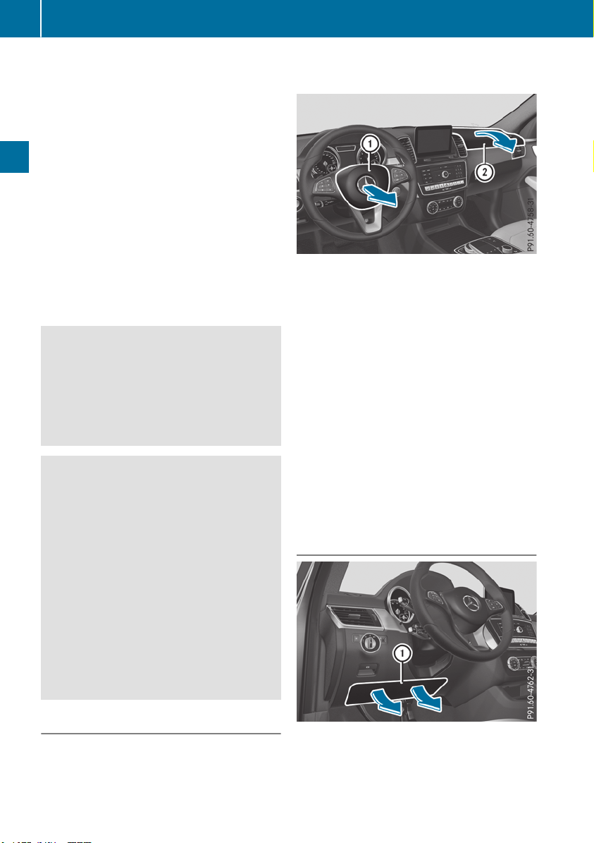
Objects in the vehicle interior may prevent
an air bag from functioning correctly. Before
starting your journey and to avoid risks resulting
from the speed of the air bag as it deploys, make
sure that:
R
there are no people, animals or objects
between the vehicle occupants and an air bag
R
there are no objects between the seat, door
and B-pillar
R
there are no hard objects, e.g. coat hangers,
hanging on the grab handles or coat hooks
R
no accessories, such as cup holders, are
attached to the vehicle within the deployment
area of an air bag, e.g. to doors, side windows,
rear side trim or side walls
R
no heavy, sharp-edged or fragile objects are in
the pockets of your clothing. Store such
objects in a suitable place
G
WARNING
If you modify the air bag cover or affix objects
such as stickers to it, the air bag can no longer
function correctly. There is an increased risk
of injury.
Never modify an air bag cover or affix objects
to it.
G
WARNING
Sensors to control the air bags are located in
the doors. Modifications or work not per-
formed correctly to the doors or door panel-
ing, as well as damaged doors, can lead to the
function of the sensors being impaired. The air
bags might therefore not function properly
anymore. Consequently, the air bags cannot
protect vehicle occupants as they are
designed to do. There is an increased risk of
injury.
Never modify the doors or parts of the doors.
Always have work on the doors or door pan-
eling carried out at a qualified specialist work-
shop.
Front air bags
!
Do not place heavy objects on the front-
passenger seat. This could cause the system
to identify the seat as being occupied. In the
event of an accident, the restraint systems on
the front-passenger side may be triggered
and have to be replaced.
Driver's air bag : deploys in front of the steer-
ing wheel. Front-passenger front air bag ;
deploys in front of and above the glove box.
When deployed, the front air bags offer addi-
tional head and thorax protection for the occu-
pants in the front seats.
The PASSENGER AIR BAG OFF indicator lamp
informs you about the status of the front-
passenger front air bag (Y page 45).
The front-passenger front air bag will only
deploy if:
R
the system, based on the OCS weight sensor
readings, detects that the front-passenger
seat is occupied (Y page 51). The
PASSENGER AIR BAG OFF indicator lamp is
not lit (Y page 52)
R
the restraint system control unit predicts a
high accident severity
Driver's knee bag
Driver's knee bag : deploys under the steering
column. The driver's knee bag is deployed
together with the front air bag.
50
Occupant safety
Safety
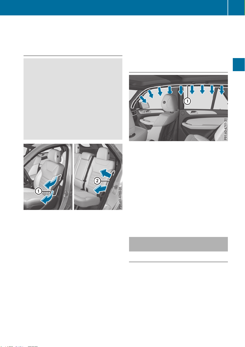
The driver's knee bag offers additional thigh,
knee and lower leg protection for the occupant
in the driver's seat.
Side impact air bags
G
WARNING
Unsuitable seat covers can obstruct or pre-
vent deployment of the air bags integrated
into the seats. Consequently, the air bags
cannot protect vehicle occupants as they are
designed to do. In addition, the operation of
the occupant classification system (OCS)
could be adversely affected. This poses an
increased risk of injury or even fatal injury.
You should only use seat covers that have
been approved for the respective seat by
Mercedes-Benz.
Front side impact air bags : and rear side
impact air bags ; deploy next to the outer bol-
ster of the seat backrest.
When deployed, the side impact air bag offers
additional thorax protection. It also offers addi-
tional pelvis protection for occupants in the
front seats. However, it does not protect the:
R
Head
R
Neck
R
Arms
If the restraint system control unit detects a side
impact, the side impact air bag is deployed on
the side on which the impact occurs.
The side impact air bag on the front-passenger
side deploys under the following conditions:
R
the OCS system detects that the front-
passenger seat is occupied or
R
the seat belt buckle tongue is engaged in the
belt buckle of the front-passenger seat
If the belt tongue is engaged in the belt buckle,
the side impact air bag on the front-passenger
side deploys if an appropriate accident situation
occurs. In this case, deployment is independent
of whether the front-passenger seat is occupied
or not.
Window curtain air bags
Window curtain air bags : are integrated into
the side of the roof frame and deployed in the
area from the A-pillar to the C-pillar.
When deployed, the window curtain air bag
enhances the level of protection for the head.
However, it does not protect the chest or arms.
If the restraint system control unit detects a side
impact, the window curtain air bag is deployed
on the side on which the impact occurs.
If the system determines that they can offer
additional protection to that provided by the
seat belt, a window curtain air bag may be
deployed in other accident situations
(Y page 56).
Occupant Classification System
(OCS)
Introduction
The Occupant Classification System (OCS) cat-
egorizes the person in the front-passenger seat.
Depending on that result, the front-passenger
front air bag is either enabled or deactivated.
The system does not deactivate:
R
the side impact air bag
R
the window curtain air bag
R
the Emergency Tensioning Devices
Occupant safety
51
Safety
Z
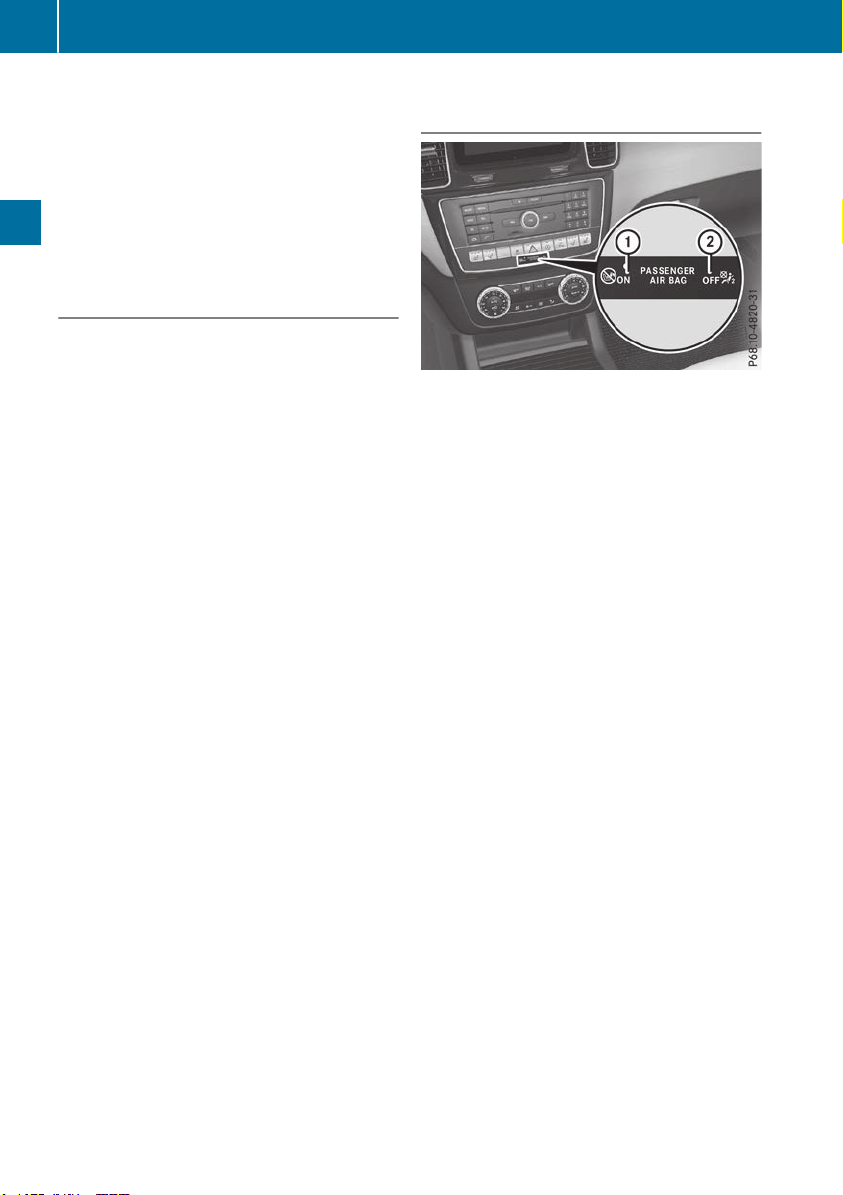
In the following situation, the side impact air bag
and the Emergency Tensioning Device are deac-
tivated:
R
OCS has not categorized the person on the
front-passenger seat as an adult or a person
of corresponding stature and
R
the seat belt buckle tongue of the seat belt is
not inserted into the front-passenger seat belt
buckle
Requirements
To be classified correctly, the front passenger
must sit:
R
with the seat belt fastened correctly
R
in an almost upright position with their back
against the seat backrest
R
with their feet resting on the floor, if possible
If the front passenger does not observe these
conditions, OCS may produce a false classifica-
tion, e.g. because the front passenger:
R
transfers their weight by supporting them-
selves on a vehicle armrest
R
sits in such a way that their weight is raised
from the seat cushion
If it is absolutely necessary to install a child
restraint system on the front-passenger seat, be
sure to observe the correct positioning of the
child restraint system. Never place objects
under or behind the child restraint system, e.g. a
cushion. The entire base of the child restraint
system must always rest on the seat cushion of
the front-passenger seat. The backrest of the
forward-facing child restraint system must lie as
flat as possible against the backrest of the front-
passenger seat.
The child restraint system must not touch the
roof or be subjected to a load by the head
restraint. Adjust the angle of the seat backrest
and the head restraint position accordingly.
Only then can OCS be guaranteed to function
correctly. Always observe the child restraint sys-
tem manufacturer's installation and operating
instructions.
Occupant Classification System opera-
tion (OCS)
:
PASSENGER AIR BAG ON indicator lamp
;
PASSENGER AIR BAG OFF indicator lamp
The indicator lamps inform you whether the
front-passenger front air bag is deactivated or
enabled.
X
Press the Start/Stop button once or twice, or
turn the SmartKey to position 1 or 2 in the
ignition lock.
The system carries out self-diagnostics.
The PASSENGER AIR BAG OFF and PASSENGER
AIR BAG ON indicator lamps must light up simul-
taneously for approximately six seconds.
The indicator lamps display the status of the
front-passenger front air bag.
R
PASSENGER AIR BAG ON lights up for 60 sec-
onds, subsequently both indicator lamps are
off (PASSENGER AIR BAG ON and OFF): the
front-passenger front air bag is able to deploy
in the event of an accident.
R
PASSENGER AIR BAG OFF lights up: the front-
passenger front air bag is deactivated. It will
then not be deployed in the event of an acci-
dent.
If the PASSENGER AIR BAG ON indicator lamp is
off, only the PASSENGER AIR BAG OFF indicator
lamp shows the status of the front-passenger
front air bag. The PASSENGER AIR BAG OFF
indicator lamp may be lit continuously or be off.
If the status of the front-passenger front air bag
changes while the vehicle is in motion, an air bag
display message appears in the instrument clus-
ter (Y page 254). When the front-passenger
seat is occupied, always pay attention to the
PASSENGER AIR BAG OFF indicator lamp. Be
aware of the status of the front-passenger front
air bag both before and during the journey.
52
Occupant safety
Safety

G
WARNING
If the PASSENGER AIR BAG OFF indicator
lamp is lit, the front-passenger front air bag is
disabled. It will not be deployed in the event of
an accident and cannot perform its intended
protective function. A person in the front-
passenger seat could then, for example, come
into contact with the vehicle's interior, espe-
cially if the person is sitting too close to the
dashboard. This poses an increased risk of
injury or even fatal injury.
When the front-passenger seat is occupied,
always ensure that:
R
the classification of the person in the front-
passenger seat is correct and the front-
passenger front air bag is enabled or disa-
bled in accordance with the person in the
front-passenger seat
R
the front-passenger seat has been moved
back as far back as possible.
R
the person is seated correctly.
Make sure, both before and during the jour-
ney, that the status of the front-passenger
front air bag is correct.
G
WARNING
If you secure a child in a rearward-facing child
restraint system on the front-passenger seat
and the PASSENGER AIR BAG OFF indicator
lamp is off, the front-passenger front air bag
can deploy in the event of an accident. The
child could be struck by the air bag. This poses
an increased risk of injury or even fatal injury.
Make sure that the front-passenger front air
bag has been deactivated. The PASSENGER
AIR BAG OFF indicator lamp must be lit.
NEVER use a rearward-facing child restraint
on a seat protected by an ACTIVE FRONT AIR-
BAG in front of it; DEATH or SERIOUS INJURY
to the child can occur.
If the PASSENGER AIR BAG OFF indicator lamp
stays off, do not install a rearward-facing child
restraint system on the front-passenger seat.
You can find more information on OCS under
"Problems with the Occupant Classification Sys-
tem" (Y page 55).
G
WARNING
If you secure a child in a forward-facing child
restraint system on the front-passenger seat
and you position the front-passenger seat too
close to the dashboard, the child could, in the
event of an accident:
R
come into contact with the vehicle's inte-
rior if the PASSENGER AIR BAG OFF indi-
cator lamp is lit, for example
R
be struck by the air bag if the PASSENGER
AIR BAG OFF indicator lamp is off
This poses an increased risk of injury or even
fatal injury.
Move the front-passenger seat as far back as
possible. Always make sure that the shoulder
belt strap is correctly routed from the vehicle
belt sash guide to the shoulder belt guide on
the child restraint system. The shoulder belt
strap must be routed forwards and down-
wards from the vehicle belt sash guide. If nec-
essary, adjust the vehicle belt sash guide and
the front-passenger seat accordingly. Always
observe the child restraint system manufac-
turer's installation instructions.
If OCS determines that:
R
The front-passenger seat is unoccupied, the
PASSENGER AIR BAG OFF indicator lamp
lights up after the system self-test and
remains lit. This indicates that the front-
passenger front air bag is deactivated.
R
The front-passenger seat is occupied by a
child of up to twelve months old, in a standard
child restraint system, the PASSENGER AIR
BAG OFF indicator lamp lights up after the
system self-test and remains lit. This indi-
cates that the front-passenger front air bag is
deactivated.
But even in the case of a twelve-month-old
child, in a standard child restraint system, the
PASSENGER AIR BAG OFF indicator lamp can
go out after the system self-test. This indi-
cates that the front-passenger front air bag is
activated. The result of the classification is
dependent on, among other factors, the child
restraint system and the child's stature. It is
recommended that you install the child
restraint system on a suitable rear seat.
Occupant safety
53
Safety
Z

R
The front-passenger seat is occupied by a
person of smaller stature (e.g. a teenager or
small adult), the PASSENGER AIR BAG OFF
indicator lamp lights up and remains lit after
the system self-test depending on the result
of the classification or, alternatively, goes out.
-
If the PASSENGER AIR BAG OFF indicator
lamp is off, move the front-passenger seat
as far back as possible. Alternatively, a per-
son of smaller stature can sit on a rear seat.
-
If the PASSENGER AIR BAG OFF indicator
lamp is lit, a person of smaller stature
should not use the front-passenger seat.
R
The front-passenger seat is occupied by an
adult or a person of adult stature, the
PASSENGER AIR BAG OFF indicator lamp
goes out after the system self-test. This indi-
cates that the front-passenger front air bag is
activated.
If children are traveling in the vehicle, be sure to
observe the notes on "Children in the vehicle"
(Y page 59).
When the Occupant Classification System
(OCS) is malfunctioning, the red 6 restraint
system warning lamp on the instrument cluster
and the PASSENGER AIR BAG OFF indicator
lamp light up simultaneously. The front-
passenger front air bag is deactivated in this
case and does not deploy during an accident.
Have the Occupant Classification System (OCS)
checked and repaired immediately at a qualified
specialist workshop. Mercedes-Benz recom-
mends that you use an authorized Mercedes-
Benz Center for this purpose.
If the front-passenger seat, the seat cover or the
seat cushion are damaged, have the necessary
repair work carried out at a qualified specialist
workshop. Mercedes-Benz recommends that
you use an authorized Mercedes-Benz Center
for this purpose.
For safety reasons, Mercedes-Benz recom-
mends that you only use seat accessories that
have been approved by Mercedes-Benz.
If the driver's air bag deploys, this does not
mean that the front-passenger front air bag will
also deploy. The Occupant Classification Sys-
tem (OCS) categorizes the occupant on the
front-passenger seat. Depending on that result,
the front-passenger front air bag is either ena-
bled or deactivated.
System self-test
G
DANGER
If the PASSENGER AIR BAG OFF and
PASSENGER AIR BAG ON indicator lamps do
not both light up during the self-test, the sys-
tem is malfunctioning. The front-passenger
front air bag might be triggered unintention-
ally or might not be triggered at all in the event
of an accident with high deceleration. This
poses an increased risk of injury or even fatal
injury.
In this case the front-passenger seat may not
be used. Do not install a child restraint system
on the front-passenger seat. Have the Occu-
pant Classification System (OCS) checked
and repaired immediately at a qualified spe-
cialist workshop.
G
WARNING
If the PASSENGER AIR BAG OFF indicator
lamp remains lit after the self-test, the front-
passenger front air bag is deactivated. It will
not be deployed in the event of an accident. In
this case, the front-passenger front air bag
cannot perform its intended protective func-
tion, e.g. when a person is seated in the front-
passenger seat.
That person could, for example, come into
contact with the vehicle's interior, especially
if the person is sitting too close to the dash-
board. This poses an increased risk of injury or
even fatal injury.
When the front-passenger seat is occupied,
always ensure that:
R
the classification of the person in the front-
passenger seat is correct and the front-
passenger front air bag is enabled or deac-
tivated in accordance with the person in the
front-passenger seat
R
the person is seated properly with a cor-
rectly fastened seatbelt
R
the front-passenger seat has been moved
as far back as possible
If the PASSENGER AIR BAG OFF indicator
lamp remains lit when it should not, the front-
54
Occupant safety
Safety

passenger seat must not be used. Do not
install a child restraint system on the front-
passenger seat. Have the Occupant Classifi-
cation System (OCS) checked and repaired
immediately at a qualified specialist work-
shop.
G
WARNING
Objects between the seat surface and the
child restraint system could affect OCS oper-
ation. This could result in the front-passenger
air bag not functioning as intended during an
accident. This poses an increased risk of
injury or even fatal injury.
Do not place any objects between the seat
surface and the child restraint system. The
entire base of the child restraint system must
always rest on the seat cushion of the front-
passenger seat. The backrest of the forward-
facing child restraint system must, as far as
possible, be resting on the backrest of the
front-passenger seat. Always comply with the
child restraint system manufacturer's instal-
lation instructions.
After the self-test, the PASSENGER AIR BAG OFF
or the PASSENGER AIR BAG ON indicator lamp
displays the status of the front-passenger front
air bag (Y page 52). If the front-passenger front
air bag is enabled, the PASSENGER AIR BAG ON
indicator lamp lights up for 60 seconds and then
goes out.
If the PASSENGER AIR BAG ON indicator lamp is
off, only the PASSENGER AIR BAG OFF indicator
lamp displays the status of the front-passenger
front air bag. The PASSENGER AIR BAG OFF
indicator lamp may be lit continuously or be off.
For more information about the OCS, see "Prob-
lems with the Occupant Classification System"
(Y page 55).
Problems with the Occupant Classification System (OCS)
Be sure to observe the notes on "System self-test" (Y page 54).
Occupant safety
55
Safety
Z

Problem
Possible causes/consequences and MM Solutions
The PASSENGER AIR
BAG OFF indicator lamp
lights up and remains lit,
even though the front-
passenger seat is occu-
pied by an adult or a per-
son of a stature corre-
sponding to that of an
adult.
The classification of the person on the front-passenger seat is incor-
rect.
X
Make sure the conditions for a correct classification of the person
on the front-passenger seat are met (Y page 52).
X
If the PASSENGER AIR BAG OFF indicator lamp remains lit, the front-
passenger seat may not be used.
X
Have OCS checked as soon as possible at an authorized Mercedes-
Benz Center.
The PASSENGER AIR
BAG OFF indicator lamp
does not light up and/or
does not stay on.
The front-passenger seat
is:
R
unoccupied
R
occupied by the
weight of a child up to
twelve months old in a
child restraint system
OCS is malfunctioning.
X
Make sure there is nothing between the seat cushion and the child
seat.
X
Make sure that the entire base of the child restraint system rests on
the seat cushion of the front-passenger seat. The backrest of the
forward-facing child restraint system must lie as flat as possible
against the backrest of the front-passenger seat. If necessary,
adjust the position of the front-passenger seat.
X
When installing the child restraint system, make sure that the seat
belt is tight. Do not pull the seat belt tight using the front-passenger
seat adjustment. This could result in the seat belt and the child
restraint system being pulled too tightly.
X
Check for correct installation of the child restraint system.
Make sure that the head restraint does not apply a load to the child
restraint system. If necessary, adjust the head restraint accord-
ingly.
X
Make sure that no objects are applying additional weight onto the
seat.
X
If the PASSENGER AIR BAG OFF indicator lamp remains off and/or
the PASSENGER AIR BAG ON indicator lamp lights up, do not install
a child restraint system on the front-passenger seat. It is recom-
mended that you install the child restraint system on a suitable rear
seat.
X
Have OCS checked as soon as possible at an authorized Mercedes-
Benz Center.
Deployment of Emergency Tensioning
Devices and air bags
Important safety notes
G
WARNING
The air bag parts are hot after an air bag has
been deployed. There is a risk of injury.
Do not touch the air bag parts. Have a
deployed air bag replaced at a qualified spe-
cialist workshop as soon as possible.
G
WARNING
A deployed air bag no longer offers any pro-
tection and cannot provide the intended pro-
tection in an accident. There is an increased
risk of injury.
Have the vehicle towed to a qualified special-
ist workshop in order to have a deployed air
bag replaced.
It is important for your safety and that of your
passenger to have deployed air bags replaced
and to have any malfunctioning air bags
56
Occupant safety
Safety

repaired. This will help to make sure the air bags
continue to perform their protective function for
the vehicle occupants in the event of a crash.
G
WARNING
Emergency Tensioning Devices that have
deployed pyrotechnically are no longer opera-
tional and are unable to perform their inten-
ded protective function. This poses an
increased risk of injury or even fatal injury.
Have pyrotechnically triggered Emergency
Tensioning Devices replaced immediately at a
qualified specialist workshop.
An electric motor is used by PRE-SAFE
®
to trig-
ger the tightening of the seat belt in hazardous
situations. This procedure is reversible.
If Emergency Tensioning Devices are triggered
or air bags are deployed, you will hear a bang,
and some powder may also be released. The
6 restraint system warning lamp lights up.
Only in rare cases will the bang affect your hear-
ing. The powder that is released generally does
not constitute a health hazard, but it may cause
short-term breathing difficulties in people with
asthma or other respiratory problems. Provided
it is safe to do so, you should leave the vehicle
immediately or open the window in order to pre-
vent breathing difficulties.
Air bags and pyrotechnic Emergency Tensioning
Devices (ETDs) contain perchlorate material,
which may require special handling and regard
for the environment. National guidelines must
be observed during disposal. In California, see
www.dtsc.ca.gov/HazardousWaste/
Perchlorate/index.cfm.
Method of operation
During the first stage of a collision, the restraint
system control unit evaluates important physi-
cal data relating to vehicle deceleration or accel-
eration, such as:
R
duration
R
direction
R
intensity
Based on the evaluation of this data, the
restraint system control unit triggers the Emer-
gency Tensioning Devices during a head-on or
rear-end collision.
An Emergency Tensioning Device can only be
triggered, if:
R
the ignition is switched on
R
the components of the restraint system are
operational. You can find further information
under "Restraint system warning lamp"
(Y page 45)
R
the seat belt buckle tongue has engaged in
the belt buckle of the respective front seat
The Emergency Tensioning Devices in the rear
passenger compartment are triggered inde-
pendently of the lock status of the seat belts.
If the restraint system control unit detects a
more severe accident, further components of
the restraint system are activated independ-
ently of each other in certain frontal collision
situations:
R
Front air bags and driver's knee bag
R
Window curtain air bag, if the system deter-
mines that deployment can offer additional
protection to that provided by the seat belt
Depending on the person in the front-passenger
seat, the front-passenger front air bag is either
disabled or enabled. The front-passenger front
air bag can be deployed in an accident only if the
PASSENGER AIR BAG OFF indicator lamp is off.
Observe the information on the PASSENGER AIR
BAG indicator lamps (Y page 45).
Your vehicle has two-stage front air bags. At the
first deployment threshold the front air bag fills
with gas. If the second deployment threshold is
then reached within a few milliseconds, the front
air bag is filled with the maximum quantity of
gas.
The activation threshold of the Emergency Ten-
sioning Devices and the air bags is determined
by evaluating the rate of vehicle deceleration or
acceleration which occurs at various points in
the vehicle. This process is pre-emptive in
nature. Deployment should take place in good
time at the start of the collision.
The rate of vehicle deceleration or acceleration
and the direction of the force are essentially
determined by:
R
the distribution of forces during the collision
R
the collision angle
R
the deformation characteristics of the vehicle
R
the characteristics of the object with which
the vehicle has collided
Factors which can only be seen and measured
after a collision has occurred do not play a deci-
sive role in the deployment of an air bag. Nor do
Occupant safety
57
Safety
Z

they provide an indication of air bag deploy-
ment.
The vehicle can be deformed considerably, with-
out an air bag being deployed. This is the case if
only parts which are relatively easily deformed
are affected and the rate of deceleration is not
high. Conversely, air bags may be deployed even
though the vehicle suffers only minor deforma-
tion. This is the case if, for example, very rigid
vehicle parts such as longitudinal body mem-
bers are hit, and sufficient deceleration occurs
as a result.
If the restraint system control unit detects a side
impact or if the vehicle rolls over, the applicable
components of the restraint system are
deployed independently of each other depend-
ing on the apparent type of accident.
R
Side impact air bags on the side where the
impact takes place, independently of the
Emergency Tensioning Device and the use of
the seat belt on the driver's seat and outer
seats in the second row
The side impact air bag on the front-
passenger side deploys under the following
conditions:
-
the OCS system detects that the front-
passenger seat is occupied or
-
the seat belt buckle tongue is engaged in
the belt buckle of the front-passenger seat
R
Window curtain air bag on the side of impact,
independently of the use of the seat belt and
independently of whether the front-
passenger seat is occupied
R
Emergency Tensioning Devices, if the system
determines that deployment can offer addi-
tional protection in this situation
R
Window curtain air bags on the driver's and
front-passenger side in certain situations
when the vehicle rolls over, if the system
determines that deployment can offer addi-
tional protection to that provided by the seat
belt
i
Not all air bags are deployed in an accident.
The different air bag systems work independ-
ently of each other.
How the air bag system works is determined
by the severity of the accident detected,
especially the vehicle deceleration or accel-
eration and the apparent type of accident:
R
Head-on collision
R
Side impact
R
Rollover
PRE-SAFE
®
(anticipatory occupant
protection system)
Introduction
In certain hazardous situations, PRE-SAFE
®
takes pre-emptive measures to protect the vehi-
cle occupants.
Important safety notes
!
Make sure that there are no objects in the
footwell or behind the seats. There is a danger
that the seats and/or objects could be dam-
aged when PRE-SAFE
®
is activated.
Although your vehicle is equipped with PRE-
SAFE
®
, the possibility of injury in the event of an
accident cannot be ruled out. Always adapt your
driving style to suit the prevailing road and
weather conditions and maintain a safe distance
from the vehicle in front. Drive carefully.
Function
PRE-SAFE
®
intervenes:
R
in emergency braking situations, e.g. when
BAS is activated
R
in critical driving situations, e.g. when physi-
cal limits are exceeded and the vehicle under-
steers or oversteers severely
R
on vehicles with the Driving Assistance PLUS
package: when Active Brake Assist intervenes
powerfully or the radar sensor system detects
an imminent danger of collision in certain sit-
uations
PRE-SAFE
®
takes the following measures
depending on the hazardous situation detected:
R
the front seat belts are pre-tensioned.
R
if the vehicle skids, the side windows and the
sliding sunroof are closed.
R
vehicles with the memory function: the front-
passenger seat is adjusted if it is in an unfav-
orable position.
R
vehicles with a multicontour seat: the air pres-
sure in the side bolsters of the seat backrest
is increased.
If the hazardous situation passes without result-
ing in an accident, PRE-SAFE
®
slackens the belt
pre-tensioning. On vehicles with multicontour
seats, the air pressure in the side bolsters is
reduced again. All settings made by PRE-SAFE
®
can then be reversed.
58
Occupant safety
Safety

If the seat belt pre-tensioning is not reduced:
X
Move the seat backrest or seat back slightly
when the vehicle is stationary.
The seat belt pre-tensioning is reduced and
the locking mechanism is released.
The seat-belt adjustment is an integral part of
the PRE-SAFE
®
convenience function. Informa-
tion about the convenience function can be
found under "Belt adjustment" (Y page 48).
PRE-SAFE
®
PLUS (anticipatory occu-
pant protection system PLUS)
Introduction
PRE-SAFE
®
PLUS is only available in vehicles
with the Driving Assistance PLUS package.
Using the radar sensor system, PRE-SAFE
®
PLUS is able to detect that a head-on or rear-end
collision is imminent. In certain hazardous sit-
uations, PRE-SAFE
®
PLUS takes pre-emptive
measures to protect the vehicle occupants.
Important safety notes
The intervention of PRE-SAFE
®
PLUS cannot
prevent an imminent collision.
The driver is not warned about the intervention
of PRE-SAFE
®
PLUS.
PRE-SAFE
®
PLUS does not intervene if the vehi-
cle is backing up.
When driving, or when parking or exiting a park-
ing space using Active Parking Assist, PRE-
SAFE
®
PLUS will not apply the brakes.
Function
PRE-SAFE
®
PLUS intervenes in certain situa-
tions if the radar sensor system detects an
imminent head-on or rear-end collision.
PRE-SAFE
®
PLUS takes the following measures
depending on the hazardous situation detected:
R
if the radar sensor system detects that a
head-on collision is imminent, the seat belts
are pre-tensioned.
R
if the radar sensor system detects that a rear-
end collision is imminent:
-
the brake pressure is increased if the driver
applies the brakes when the vehicle is sta-
tionary.
-
the seat belts are pre-tensioned.
The PRE-SAFE
®
PLUS braking application is can-
celed:
R
if the accelerator pedal is depressed when a
gear is engaged
R
if the risk of a collision passes or is no longer
detected
R
if Active Distance Assist DISTRONIC indicates
an intention to intervene
If the hazardous situation passes without result-
ing in an accident, the original settings are
restored.
Automatic measures after an acci-
dent
Immediately after an accident, the following
measures are implemented, depending on the
type and severity of the impact:
R
the hazard warning lamps are switched on
R
the emergency lighting is activated
R
the vehicle doors are unlocked
R
the front side windows are lowered
R
vehicles with a memory function: the electri-
cally adjustable steering wheel is raised when
the driver's door is opened
R
the engine is switched off and the fuel supply
is cut off
R
vehicles with Mercedes me connect: auto-
matic emergency call
Children in the vehicle
Important safety notes
Accident statistics show that children secured
in the rear seats are safer than children secured
in the front-passenger seat. For this reason,
Mercedes-Benz strongly advises that you install
Children in the vehicle
59
Safety
Z

a child restraint system on a rear seat. Children
are generally better protected there.
If a child younger than twelve years old and
under 5 ft (1.50 m) in height is traveling in the
vehicle:
R
always secure the child in a child restraint
system suitable for Mercedes-Benz vehicles.
The child restraint system must be appropri-
ate to the age, weight and size of the child.
R
be sure to observe the instructions and safety
notes in this section in addition to the child
restraint system manufacturer's installation
instructions.
R
always observe the instructions and safety
notes on the "Occupant classification system
(OCS)". (Y page 51)
G
WARNING
If you leave children unsupervised in the vehi-
cle, they could set it in motion by, for example:
R
release the parking brake.
R
shift the automatic transmission out of the
parking position P.
R
start the engine.
In addition, they may operate vehicle equip-
ment and become trapped. There is a risk of
an accident and injury.
When leaving the vehicle, always take the
SmartKey with you and lock the vehicle. Never
leave children unsupervised in the vehicle.
G
WARNING
If persons, particularly children are subjected
to prolonged exposure to extreme heat or
cold, there is a risk of injury, possibly even
fatal. Never leave children unattended in the
vehicle.
G
WARNING
If the child restraint system is subjected to
direct sunlight, parts may get very hot. Chil-
dren may burn themselves on these parts,
particularly on the metal parts of the child
restraint system. There is a risk of injury.
If you leave the vehicle, taking the child with
you, always ensure that the child restraint
system is not exposed to direct sunlight. Pro-
tect it with a blanket, for example. If the child
restraint system has been exposed to direct
sunlight, let it cool down before securing the
child in it. Never leave children unattended in
the vehicle.
Always ensure that all vehicle occupants have
their seat belts fastened correctly and are sitting
properly. Particular attention must be paid to
children.
Observe the safety notes on the seat belt
(Y page 46) and the notes on correct use of seat
belts (Y page 47).
A booster seat may be necessary to achieve
proper seat belt positioning for children over
40 lbs (18 kg) until they reach a height where a
three-point seat belt can be properly fastened
without a booster seat.
Special seatbelt retractor
G
WARNING
If the seat belt is released while driving, the
child restraint system will no longer be
secured properly. The special seat belt retrac-
tor is disabled and the inertia real draws in a
portion of the seat belt. The seat belt cannot
be immediately refastened. There is an
increased risk of injury, possibly even fatal.
Stop the vehicle immediately, paying atten-
tion to road and traffic conditions. Reactivate
the special seat belt retractor and secure the
child restraint system properly.
All seat belts in the vehicle, except the driver's
seat belt, are equipped with a special seat belt
retractor. When activated, the special seat belt
retractor ensures that the seat belt cannot
slacken once the child seat is secured.
Installing a child restraint system:
X
Make sure you observe the child restraint
system manufacturer's installation instruc-
tions.
X
Pull the seat belt smoothly from the belt out-
let.
X
Engage seat belt tongue in belt buckle.
60
Children in the vehicle
Safety

Activating the special seat belt retractor:
X
Pull the seat belt out fully and let the inertia
reel retract it again.
While the seat belt is retracting, you should
hear a ratcheting sound. The special seat belt
retractor is enabled.
X
Push the child restraint system down so that
the seat belt is tight and does not loosen.
Removing the child restraint system and deac-
tivating the special seat belt retractor:
X
Make sure you observe the child restraint
system manufacturer's installation instruc-
tions.
X
Press the release button of the seat belt
buckle and guide the seat belt tongue back
towards the belt sash guide.
The special seat belt retractor is deactivated.
Child restraint system
The use of seat belts and child restraint systems
is required by law in:
R
all 50 states
R
the U.S. territories
R
the District of Columbia
R
all Canadian provinces
If you install a rearward-facing child restraint
system on the center rear seat, the rear armrest
must be folded back as far as possible.
You can obtain further information about the
correct child restraint system from any author-
ized Mercedes-Benz Center.
G
WARNING
If the child restraint system is installed incor-
rectly on a suitable seat, it cannot protect as
intended. The child cannot then be restrained
in the event of an accident, heavy braking or
sudden changes of direction. There is an
increased risk of injury, possibly even fatal.
Make sure that you observe the child restraint
system manufacturer's installation instruc-
tions and the notes on use. Please ensure,
that the base of the child restraint system is
always resting completely on the seat cush-
ion. Never place objects, e.g. cushions, under
or behind the child restraint system. Only use
child restraint systems with the original cover
designed for them. Only replace damaged
covers with genuine covers.
G
WARNING
If the child restraint system is installed incor-
rectly or is not secured, it can come loose in
the event of an accident, heavy braking or a
sudden change in direction. The child
restraint system could be thrown about, strik-
ing vehicle occupants. There is an increased
risk of injury, possibly even fatal.
Always install child restraint systems prop-
erly, even if they are not being used. Make
sure that you observe the child restraint sys-
tem manufacturer's installation instructions.
You will find further information on stowing
objects, luggage or loads under "Loading guide-
lines" (Y page 295).
G
WARNING
Child restraint systems or their securing sys-
tems which have been damaged or subjected
to a load in an accident can no longer protect
as intended. The child cannot then be
restrained in the event of an accident, heavy
braking or sudden changes of direction. There
is an increased risk of injury, possibly even
fatal.
Replace child restraint systems which have
been damaged or subjected to a load in an
accident as soon as possible. Have the secur-
ing systems on the child restraint system
checked at a qualified specialist workshop,
before you install a child restraint system
again.
The securing systems of child restraint systems
are:
R
the seat belt system
R
the LATCH-type (ISOFIX) securing rings
R
the Top Tether anchorages
If it is absolutely necessary to carry a child on
the front passenger seat, be sure to observe the
information on the "Occupant Classification
System (OCS)" (Y page 51). There you will also
find information on disabling the front
passenger front air bag.
Children in the vehicle
61
Safety
Z
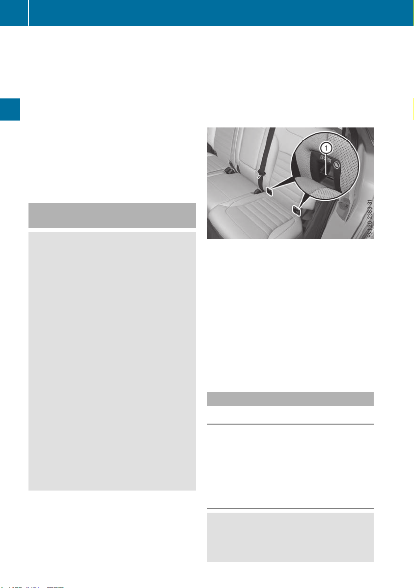
All child restraint systems must meet the fol-
lowing standards:
R
U.S. Federal Motor Vehicle Safety Standards
213 and 225
R
Canadian Motor Vehicle Safety Standards
213 and 210.2
Confirmation that the child restraint system cor-
responds to the standards can be found on an
instruction label on the child restraint system.
This confirmation can also be found in the instal-
lation instructions that are included with the
child restraint system.
Observe the warning labels in the vehicle inte-
rior and on the child restraint system.
LATCH-type (ISOFIX) child seat secur-
ing system
G
WARNING
For LATCH-type (ISOFIX) child restraint sys-
tems in which the child is secured using the
safety belt integrated in the child restraint
system, the maximum permissible weight of
the child and child restraint system together
is 73 lbs (33 kg).
If the child and the child restraint system
together weigh more than 73 lbs (33 kg), the
LATCH-type (ISOFIX) child restraint system
with integrated safety belt no longer offers
sufficient protection. The LATCH-type (ISO-
FIX) child seat securing system may be over-
loaded, and the child may not be restrained in
an accident, for example. This poses an
increased risk of injury or even fatal injury.
If the child and the child restraint system
together weigh more than 73 lbs(33 kg), use
only a LATCH-type (ISOFIX) child restraint sys-
tem in which the child is also secured with the
vehicle seat belt. Also secure the child
restraint system with the Top Tether belt, if
available.
Regularly check that the permissible gross
weight of the child together with the child
restraint system is still maintained.
Always comply with the manufacturer's instal-
lation and operating instructions for the child
restraint system used.
Before every trip, make sure that the LATCH-
type (ISOFIX) child restraint system is engaged
correctly in both LATCH-type (ISOFIX) securing
rings
!
When installing the child restraint system,
make sure that the seat belt for the middle
seat does not get trapped. The seat belt could
otherwise be damaged.
X
Install the LATCH-type (ISOFIX) child restraint
system on both LATCH-type (ISOFIX) securing
rings :.
LATCH-type (ISOFIX) is a standardized securing
system for specially designed child restraint
systems on the rear seats. LATCH-type (ISOFIX)
securing rings for two LATCH-type (ISOFIX) child
restraint systems are installed on the left and
right of the rear seats.
Non-LATCH-type (ISOFIX) child seats may also
be used and can be installed using the vehicle's
seat belt system. Install the child seat according
to the manufacturer's instructions.
Top Tether
Introduction
Top Tether provides an additional connection
between the child restraint system secured with
a LATCH-type (ISOFIX) system and the vehicle.
This helps reduce the risk of injury even further.
If the child restraint system is equipped with a
Top Tether belt, this should always be used.
Important safety notes
G
WARNING
If the rear seat backrests are not locked, they
could fold forwards in the event of an acci-
dent, heavy braking or sudden changes of
62
Children in the vehicle
Safety
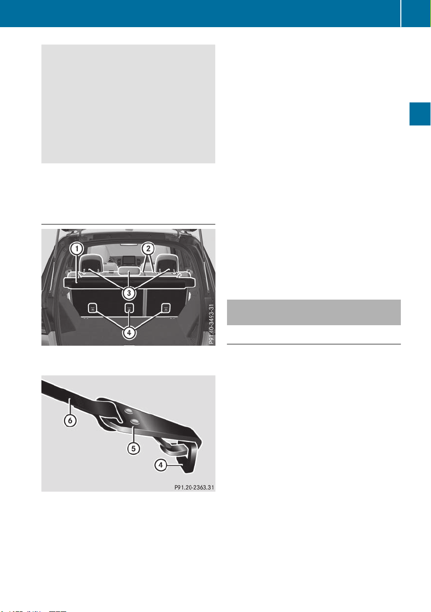
direction. As a result, child restraint systems
cannot perform their intended protective
function. Rear seat backrests that are not
locked can also cause additional injuries, e.g.
in the event of an accident. This poses an
increased risk of injury or even fatal injury.
Always lock rear seat backrests after instal-
ling a Top Tether belt. Adjust the rear seat
backrests so that they are in an upright posi-
tion.
Make sure that the backrest in the rear com-
partment engages fully. To do so, pull firmly on
the seat backrest.
Top Tether anchorages
Top Tether anchorages ? are located on the
rear side of the seat backrests.
X
Move head restraint = upwards
(Y page 100).
X
Install the LATCH-type (ISOFIX) child restraint
system with Top Tether. Always comply with
the child restraint system manufacturer's
installation instructions when doing so.
X
Route Top Tether belt B under head restraint
= between the two head restraint bars.
X
Guide Top Tether belt B down between cargo
compartment cover : and seat backrest ;.
X
Hook Top Tether hook A of Top Tether belt
B into Top Tether anchorage ?.
Make sure that:
R
Top Tether hook A is hooked into Top
Tether anchorage ? as shown.
R
Top Tether belt B is not twisted.
R
Top Tether belt B is routed between seat
backrest ; and cargo compartment
cover : if cargo compartment cover : is
installed.
R
Top Tether belt B is routed between seat
backrest ; and the cargo net if the cargo
net is installed.
X
Tension Top Tether belt B. Always comply
with the child restraint system manufactur-
er's installation instructions when doing so.
X
Move head restraint = back down again
slightly if necessary (Y page 100). Make sure
that you do not interfere with the correct rout-
ing of Top Tether belt B.
Child restraint system on the front-
passenger seat
General notes
Accident statistics show that children secured
in the rear seats are safer than children secured
in the front-passenger seat. For this reason,
Mercedes-Benz strongly advises that you install
the child restraint system on a rear seat.
If it is absolutely necessary to install a child
restraint system on the front-passenger seat,
always observe the instructions and safety
notes on the "Occupant Classification System
(OCS)" (Y page 51).
You can thus avoid the risks that could arise as
a result of:
R
an incorrectly categorized person in the front-
passenger seat
R
deactivating the front passenger front air bag
unintentionally
R
the unsuitable positioning of the child
restraint system, e.g. too close to the dash-
board
Children in the vehicle
63
Safety
Z

Rearward-facing child restraint system
If circumstances require you to secure a child in
a rearward-facing child restraint system on the
front-passenger seat, always make sure that the
front passenger front air bag is deactivated.
Only if the PASSENGER AIR BAG OFF indicator
lamp is lit continuously (Y page 45), is the front
passenger front air bag deactivated.
Always observe the child restraint system man-
ufacturer's installation and operating instruc-
tions.
Forward-facing child restraint system
If it is absolutely necessary to install a forward-
facing child restraint system on the front-
passenger seat, always move the front-
passenger seat as far back as possible. The
entire base of the child restraint system must
always rest on the seat cushion of the front-
passenger seat. The backrest of the child
restraint system must lie as flat as possible
against the backrest of the front-passenger
seat. The child restraint system must not touch
the roof or be subjected to a load by the head
restraint. Adjust the angle of the seat backrest
and the head restraint position accordingly.
Always make sure that the shoulder belt strap is
correctly routed from the vehicle belt outlet to
the shoulder belt guide on the child restraint
system. The shoulder belt strap must be routed
forward and down from the vehicle belt outlet. If
necessary, adjust the vehicle belt outlet and the
front-passenger seat accordingly.
Always observe the child restraint system man-
ufacturer's installation and operating instruc-
tions.
Child-proof locks
Important safety notes
G
WARNING
If children are traveling in the vehicle, they
could:
R
open doors, thus endangering other people
or road users
R
exit the vehicle and be caught by oncoming
traffic
R
operate vehicle equipment and become
trapped
There is a risk of an accident and injury.
Always activate the child-proof locks and
override feature if children are traveling in the
vehicle. When leaving the vehicle, always take
the key with you and lock the vehicle. Never
leave children unattended in the vehicle.
Override feature for:
R
the rear doors (Y page 65)
R
the rear side windows (Y page 65)
G
WARNING
If you leave children unsupervised in the vehi-
cle, they could set it in motion by, for example:
R
release the parking brake.
R
shift the automatic transmission out of the
parking position P.
R
start the engine.
In addition, they may operate vehicle equip-
ment and become trapped. There is a risk of
an accident and injury.
When leaving the vehicle, always take the
SmartKey with you and lock the vehicle. Never
leave children unsupervised in the vehicle.
G
WARNING
If persons, particularly children are subjected
to prolonged exposure to extreme heat or
cold, there is a risk of injury, possibly even
fatal. Never leave children unattended in the
vehicle.
64
Children in the vehicle
Safety
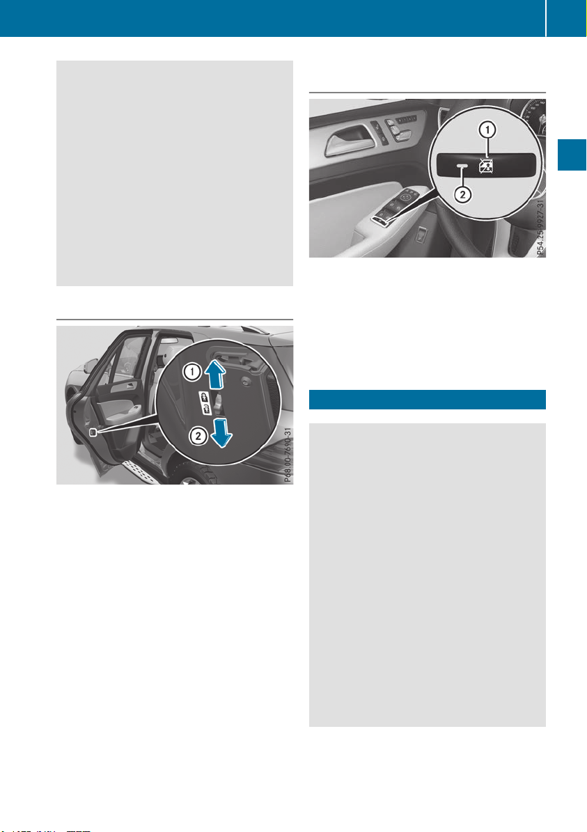
G
WARNING
If the child restraint system is subjected to
direct sunlight, parts may get very hot. Chil-
dren may burn themselves on these parts,
particularly on the metal parts of the child
restraint system. There is a risk of injury.
If you leave the vehicle, taking the child with
you, always ensure that the child restraint
system is not exposed to direct sunlight. Pro-
tect it with a blanket, for example. If the child
restraint system has been exposed to direct
sunlight, let it cool down before securing the
child in it. Never leave children unattended in
the vehicle.
Child-proof locks for the rear doors
You secure each door individually with the child-
proof locks on the rear doors. A door secured
with a child-proof lock cannot be opened from
inside the vehicle. When the vehicle is unlocked,
the door can be opened from the outside.
X
To activate: press the child-proof lock lever
up in the direction of arrow :.
X
Make sure that the child-proof locks are work-
ing properly.
X
To deactivate: press the child-proof lock
lever down in the direction of arrow ;.
Child-proof lock for the rear side win-
dows
X
To activate/deactivate: press button :.
If indicator lamp ; is lit, operation of the rear
side windows is disabled. Operation is only
possible using the switches in the driver's
door. If indicator lamp ; is off, operation is
possible using the switches in the rear com-
partment.
Pets in the vehicle
G
WARNING
If you leave animals unsupervised or unse-
cured in the vehicle, they may press buttons
or switches, for instance.
In this way, animals may:
R
activate vehicle equipment and become
trapped, for example
R
switch systems on or off and thereby
endanger other road users
Furthermore, unsecured animals may be flung
around inside the vehicle in the event of an
accident or abrupt steering or braking maneu-
ver, and thereby injure vehicle occupants.
There is a risk of accident and injury.
Never leave animals unattended in the vehi-
cle.
Always secure animals properly when driving,
for instance with a suitable pet carrier.
Pets in the vehicle
65
Safety
Z

Driving safety systems
Overview of driving safety systems
In this section, you will find information about
the following driving safety systems:
R
ABS (Anti-lock Braking System)
(Y page 66)
R
BAS (Brake Assist System) (Y page 67)
R
Active Brake Assist (Y page 67)
R
ESP
®
(Electronic Stability Program)
(Y page 70)
R
EBD (Electronic Brake force Distribution)
(Y page 72)
R
ADAPTIVE BRAKE (Y page 72)
R
Active Brake Assist with cross-traffic function
(Y page 72)
R
Active Steering Assist STEER CONTROL
(Y page 75)
Important safety notes
If you fail to adapt your driving style or if you are
inattentive, the driving safety systems can nei-
ther reduce the risk of an accident nor override
the laws of physics. Driving safety systems are
merely aids designed to assist driving. You are
responsible for maintaining the distance to the
vehicle in front, for vehicle speed, for braking in
good time, and for staying in lane. Always adapt
your driving style to suit the prevailing road and
weather conditions and maintain a safe distance
from the vehicle in front. Drive carefully.
The driving safety systems described only work
as effectively as possible when there is ade-
quate contact between the tires and the road
surface. Pay particular attention to the informa-
tion regarding tires, recommended minimum
tire tread depths etc. in the "Wheels and tires"
section (Y page 351).
In wintry driving conditions, always use winter
tires (M+S tires)and if necessary, snow chains.
Only in this way will the driving safety systems
described in this section work as effectively as
possible.
ABS (Anti-lock Braking System)
General information
ABS regulates brake pressure in such a way that
the wheels do not lock when you brake. This
allows you to continue steering the vehicle when
braking.
The ! ABS warning lamp in the instrument
cluster lights up when the ignition is switched
on. It goes out when the engine is running.
ABS works from a speed of about 5 mph
(8 km/h), regardless of road-surface conditions.
ABS works on slippery surfaces, even when you
only brake gently.
Important safety notes
i
Observe the "Important safety notes" sec-
tion (Y page 66).
G
WARNING
If ABS is faulty, the wheels could lock when
braking. The steerability and braking charac-
teristics may be severely impaired. Addition-
ally, further driving safety systems are deac-
tivated. There is an increased danger of skid-
ding and accidents.
Drive on carefully. Have ABS checked imme-
diately at a qualified specialist workshop.
When ABS is malfunctioning, other systems,
including driving safety systems, will also
become inoperative. Observe the information
on the ABS warning lamp (Y page 277) and dis-
play messages which may be shown in the
instrument cluster (Y page 245).
Brakes
X
If ABS intervenes: continue to depress the
brake pedal vigorously until the braking sit-
uation is over.
X
To make a full brake application: depress
the brake pedal with full force.
If ABS intervenes when braking, you will feel a
pulsing in the brake pedal.
The pulsating brake pedal can be an indication
of hazardous road conditions, and functions as a
reminder to take extra care while driving.
66
Driving safety systems
Safety

Off-road ABS
An ABS system specifically suited to off-road
terrain is activated automatically once the off-
road program is activated on:
R
Vehicles without the Offroad Engineering
package (Y page 215)
R
Vehicles with the Off-Road Engineering pack-
age (Y page 216)
At speeds below 20 mph (30 km/h), the front
wheels lock cyclically during braking. The dig-
ging-in effect achieved in the process reduces
the stopping distance on off-road terrain. This
limits steering capability.
BAS (Brake Assist System)
General information
BAS operates in emergency braking situations.
If you depress the brake pedal quickly, BAS
automatically boosts the braking force, thus
shortening the stopping distance.
Important safety notes
i
Observe the "Important safety notes" sec-
tion (Y page 66).
G
WARNING
If BAS is malfunctioning, the braking distance
in an emergency braking situation is
increased. There is a risk of an accident.
In an emergency braking situation, depress
the brake pedal with full force. ABS prevents
the wheels from locking.
Braking
X
Keep the brake pedal firmly depressed until
the emergency braking situation is over.
ABS prevents the wheels from locking.
The brakes will function as usual once you
release the brake pedal. BAS is deactivated.
Active Brake Assist
General information
i
Observe the "Important safety notes" sec-
tion (Y page 66).
Active Brake Assist consists of a distance warn-
ing function with an autonomous braking func-
tion and situation-dependent braking assis-
tance.
Active Brake Assist can help you to minimize the
risk of a collision with the vehicle traveling in
front or reduce the effects of such a collision.
If Active Brake Assist detects that there is a risk
of collision, you will be warned visually and
acoustically. If you do not react to the visual and
audible collision warning, autonomous braking
can be initiated in critical situations. If you apply
the brake yourself in a critical situation, Active
Brake Assist supports you with situation-
dependent braking assistance.
Active Brake Assist is only available in certain
countries.
Important safety notes
In particular, the detection of obstacles can be
impaired if:
R
there is dirt on the sensors or anything else
covering the sensors
R
there is snow or heavy rain
R
there is interference by other radar sources
R
there are strong radar reflections, for exam-
ple in parking garages
R
a narrow vehicle is traveling in front, e.g. a
motorbike
R
a vehicle is traveling in front on a different line
R
you are driving a new vehicle or servicing on
the Active Brake Assist system has just been
carried out
Observe the notes in the section on breaking-
in (Y page 134).
Following damage to the front end of the vehicle,
have the configuration and operation of the
radar sensor checked at a qualified specialist
workshop. This also applies to collisions at slow
speeds where there is no visible damage to the
front of the vehicle.
Driving safety systems
67
Safety
Z

Activating/deactivating
Active Brake Assist is automatically active after
switching on the ignition.
You can activate or deactivate Active Brake
Assist (Y page 238) in the on-board computer.
When deactivated, the distance warning func-
tion and the autonomous braking function are
also deactivated.
If Active Brake Assist is deactivated, the æ
symbol appears in the assistance graphic dis-
play.
If DSR (Y page 214) is activated, Active Brake
Assist is deactivated.
Distance warning function
General information
The distance warning function can help you to
minimize the risk of a front-end collision with a
vehicle ahead or reduce the effects of such a
collision. If the distance warning function
detects that there is a risk of a collision, you will
be warned visually and acoustically.
Important safety notes
i
Observe the "Important safety notes" sec-
tion for driving safety systems (Y page 66).
G
WARNING
The distance warning function does not react:
R
to people or animals
R
to oncoming vehicles
R
to crossing traffic
R
when cornering
The distance warning function may not give
warnings in all critical situations. There is a
risk of an accident.
Always pay careful attention to the traffic sit-
uation and be ready to brake.
Always adapt your speed to suit the prevailing
road and traffic conditions.
G
WARNING
The distance warning function cannot always
clearly identify objects and complex traffic
situations.
In such cases, the distance warning function
may:
R
give an unnecessary warning
R
not give a warning
There is a risk of an accident.
Always pay careful attention to the traffic sit-
uation and do not rely solely on the distance
warning function.
Function
Starting at a speed of around 4 mph (7 km/h),
the distance warning function warns you if you
rapidly approach a vehicle in front. An intermit-
tent warning tone will then sound, and the ·
distance warning lamp will light up in the instru-
ment cluster.
X
Brake immediately in order to increase the
distance from the vehicle in front.
or
X
Take evasive action, provided it is safe to do
so.
Due to the nature of the system, particularly
complicated but non-critical driving conditions
may also cause the system to display a warning.
With the help of the radar sensor system, the
distance warning function can detect obstacles
that are in the path of your vehicle for an exten-
ded period of time.
Up to a speed of around 44 mph (70 km/h), the
distance warning function can also react to sta-
tionary obstacles, such as stopped or parked
vehicles.
Autonomous braking function
If the driver does not react to the distance warn-
ing signal in a critical situation, Active Brake
Assist can assist the driver with the autonomous
braking function.
Vehicles without Active Distance Assist
DISTRONIC: the autonomous braking function
is available in the following speed ranges:
R
4 - 65 mph (7 - 105 km/h) for moving objects
R
4 - 31 mph (7 - 50 km/h) for stationary
objects
68
Driving safety systems
Safety

Vehicles with Active Distance Assist
DISTRONIC: the autonomous braking function
is available in the following speed ranges:
R
4 - 124 mph (7 - 200 km/h) for moving
objects
R
4 - 31 mph (7 - 50 km/h) for stationary
objects
Due to the nature of the system, particularly
complicated but non-critical driving conditions
may also cause the Autonomous Braking Func-
tion to intervene.
If the autonomous braking function requires a
particularly high braking force, preventative
passenger protection measures (PRE-SAFE
®
)
are activated simultaneously (Y page 58).
Situation-dependent braking assis-
tance
General information
i
Observe the "Important safety notes" sec-
tion (Y page 66).
With the help of the radar sensor system, Active
Brake Assist can detect obstacles that are in the
path of your vehicle for an extended period of
time.
If Active Brake Assist detects a risk of collision
with the vehicle in front, it calculates the brake
pressure necessary to avoid a collision. If you
apply the brakes forcefully, situation-dependent
braking assistance adapts to the situation and
automatically increases the brake pressure to a
degree appropriate to the traffic situation.
Situation-dependent braking assistance pro-
vides braking assistance in hazardous situations
at speeds above 4 mph (7 km/h). It uses radar
sensor technology to assess the traffic situa-
tion.
Situation-dependent braking assistance is capa-
ble of reacting to moving objects that have
already been detected as such at least once
over the period of observation, up to vehicle
speeds of around 155 mph (250 km/h).
Situation-dependent braking assistance reacts
to stationary obstacles up to a speed of approx-
imately 44 mph (70 km/h).
If situation-dependent braking assistance
demands particularly high brake pressure, pre-
ventative passenger protection measures (PRE-
SAFE
®
) are triggered simultaneously
(Y page 58).
X
Keep the brake pedal depressed until the
emergency braking situation is over.
ABS prevents the wheels from locking.
The brakes will work normally again if:
R
you release the brake pedal
R
there is no longer any danger of a collision
R
no obstacle is detected in front of your vehi-
cle.
Situation-dependent braking assistance is then
deactivated.
Important safety notes
i
Observe the "Important safety notes" sec-
tion for driving safety systems (Y page 66).
G
WARNING
Adaptive Brake Assist cannot always clearly
identify objects and complex traffic situa-
tions.
In such cases, Adaptive Brake Assist might:
R
intervene unnecessarily
R
not intervene
There is a risk of an accident.
Always pay careful attention to the traffic sit-
uation and be ready to brake. Terminate the
intervention in a non-critical driving situation.
G
WARNING
Adaptive Brake Assist does not react:
R
to people or animals
R
to oncoming vehicles
R
to crossing traffic
R
when cornering
As a result, Adaptive Brake Assist may not
intervene in all critical conditions. There is a
risk of an accident.
Always pay careful attention to the traffic sit-
uation and be ready to brake.
Due to the nature of the system, complex but
non-critical driving conditions may also cause
Active Brake Assist to intervene.
Even if Active Brake Assist is not available due to
a malfunction in the radar sensor system, the
brake system is still available with full brake
boosting effect and BAS.
Driving safety systems
69
Safety
Z

ESP
®
(Electronic Stability Program)
General notes
i
Observe the "Important safety notes" sec-
tion (Y page 66).
ESP
®
monitors driving stability and traction, i.e.
power transmission between the tires and the
road surface.
If ESP
®
detects that the vehicle is deviating from
the direction desired by the driver, one or more
wheels are braked to stabilize the vehicle. The
engine output is also modified to keep the vehi-
cle on the desired course within physical limits.
ESP
®
assists the driver when pulling away on
wet or slippery roads. ESP
®
can also stabilize
the vehicle during braking.
ETS/4ETS (Electronic Traction System)
ETS traction control is part of ESP
®
. On vehicles
with 4MATIC, 4ETS is part of ESP
®
.
Traction control brakes the drive wheels indi-
vidually if they spin. This enables you to pull
away and accelerate on slippery surfaces, for
example if the road surface is slippery on one
side. In addition, more drive torque is transfer-
red to the wheel or wheels with traction.
Traction control remains active, even if you
deactivate ESP
®
.
In appropriate driving situations, activate the
off-road program:
X
Vehicles without the Offroad Engineering
package (Y page 215)
X
Vehicles with the Off-Road Engineering pack-
age (Y page 216)
Off-road 4ETS (Electronic Traction Sys-
tem)
An ETS system specifically suited to off-road
terrain is activated automatically once the off-
road program is activated:
R
Vehicles without the Offroad Engineering
package (Y page 215)
R
Vehicles with the Off-Road Engineering pack-
age (Y page 216)
Important safety notes
G
WARNING
If ESP
®
is malfunctioning, ESP
®
is unable to
stabilize the vehicle. Additionally, further driv-
ing safety systems are deactivated. This
increases the risk of skidding and an accident.
Drive on carefully. Have ESP
®
checked at a
qualified specialist workshop.
!
Vehicles with 4MATIC: only operate the
vehicle for a maximum of ten seconds on a
brake test dynamometer. Switch off the igni-
tion.
Application of the brakes by ESP
®
may oth-
erwise destroy the brake system.
!
Vehicles with 4MATIC: function or perform-
ance tests may only be carried out on a 2-axle
dynamometer. Before you operate the vehicle
on such a dynamometer, please consult a
qualified workshop. You could otherwise
damage the drive train or the brake system.
ESP
®
is only deactivated if the å warning
lamp is lit continuously.
If the ÷ warning lamp and the å warning
lamp are lit continuously, ESP
®
is not available
due to a malfunction.
Observe the information on warning lamps
(Y page 279) and display messages which may
be shown in the instrument cluster
(Y page 245).
i
Only use wheels with the recommended tire
sizes. Only then will ESP
®
function properly.
Characteristics of ESP
®
General information
If the ÷ ESP warning lamp goes out before
beginning the journey, ESP
®
is automatically
active.
If ESP
®
intervenes, the ÷ ESP
®
warning lamp
flashes in the instrument cluster.
70
Driving safety systems
Safety
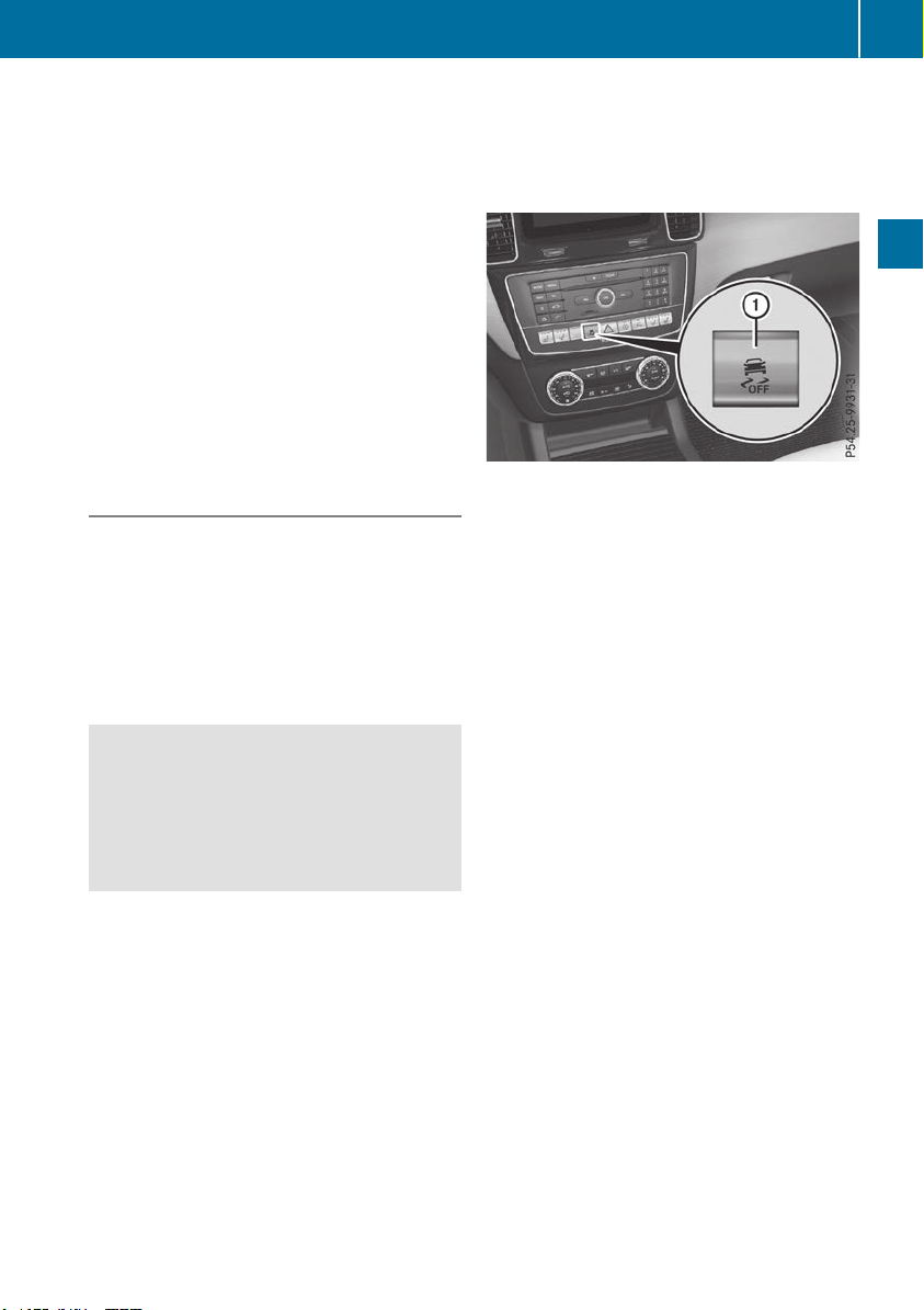
If ESP
®
intervenes:
X
Do not deactivate ESP
®
under any circum-
stances.
X
Only depress the accelerator pedal as far as
necessary when pulling away.
X
Adapt your driving style to suit the prevailing
road and weather conditions.
ECO start/stop function
The ECO start/stop function switches the
engine off automatically when the vehicle stops
moving. The engine starts automatically when
the driver wants to pull away again. ESP
®
remains in its previously selected status, e.g. if
ESP
®
was deactivated before the engine was
automatically switched off.
Deactivating/activating ESP
®
Important safety notes
i
Observe the "Important safety notes" sec-
tion (Y page 66).
You can select between the following states of
ESP
®
:
R
ESP
®
is activated.
R
ESP
®
is deactivated.
G
WARNING
If you deactivate ESP
®
, ESP
®
no longer sta-
bilizes the vehicle. There is an increased risk
of skidding and an accident.
Only deactivate ESP
®
in the situations descri-
bed in the following.
It may be best to deactivate ESP
®
in the follow-
ing situations:
R
when using snow chains
R
in deep snow
R
on sand or gravel
Spinning the wheels results in a cutting action
which provides better grip.
i
Activate ESP
®
as soon as the situations
described above no longer apply. ESP
®
will
otherwise not be able to stabilize the vehicle if
the vehicle starts to skid or a wheel starts to
spin.
!
Avoid spinning the driven wheels for an
extended period with ESP
®
deactivated. You
could otherwise damage the drivetrain.
Deactivating/activating ESP
®
X
To deactivate: press button :.
The å ESP
®
OFF warning lamp in the
instrument cluster lights up.
X
To activate: press button :.
The å ESP
®
OFF warning lamp in the
instrument cluster goes out.
Characteristics when ESP
®
is deactivated
If ESP
®
is deactivated and one or more wheels
start to spin, the ÷ ESP
®
warning lamp in the
instrument cluster flashes. In such situations,
ESP
®
will not stabilize the vehicle.
If you deactivate ESP
®
:
R
ESP
®
no longer improves driving stability.
R
Engine torque is no longer limited and the
drive wheels are able to spin.
R
Traction control is still activated.
R
Active Brake Assist is no longer available; nor
is it activated if you brake firmly with assis-
tance from ESP
®
R
PRE-SAFE
®
is no longer available, nor is it
activated if you brake firmly and ESP
®
inter-
venes.
R
Active Brake Assist with cross-traffic function
is no longer available; nor is it activated if you
brake firmly with assistance from ESP
®
R
ESP
®
still provides support when you brake
firmly.
Driving safety systems
71
Safety
Z

Offroad ESP
®
(vehicles with Off-Road
Engineering package)
An ESP
®
system specifically suited to off-road
terrain is activated automatically once the off-
road program is activated on:
R
Vehicles without the Offroad Engineering
package (Y page 215)
R
Vehicles with the Off-Road Engineering pack-
age (Y page 216)
Offroad ESP
®
intervenes with a delay if there is
oversteering or understeering, thus improving
traction.
Crosswind Assist
General information
Strong crosswind gusts can impair the ability of
your vehicle to drive straight ahead. The cross-
wind driving assistance function integrated in
ESP
®
noticeably reduces these impairments.
ESP
®
intervenes automatically according to the
direction and intensity of the crosswinds affect-
ing your vehicle.
ESP
®
intervenes with stabilizing braking to
assist you in keeping the vehicle in the lane.
Crosswind Assist is active at vehicle speeds
above 50 mph (80 km/h) when driving straight
ahead or cornering gently.
Important safety notes
Crosswind Assist does not work if ESP
®
is
switched off or deactivated because of a mal-
function.
EBD (electronic brake force distribu-
tion)
General information
EBD monitors and controls the brake pressure
on the rear wheels to improve driving stability
while braking.
Important safety notes
i
Observe the "Important safety notes" sec-
tion for driving safety systems (Y page 66).
G
WARNING
If EBD is malfunctioning, the rear wheels can
lock, e.g. under full braking. This increases the
risk of skidding and an accident.
You should therefore adapt your driving style
to the different handling characteristics. Have
the brake system checked at a qualified spe-
cialist workshop.
Observe information regarding indicator and
warning lamps (Y page 277) as well as display
messages (Y page 247).
ADAPTIVE BRAKE
ADAPTIVE BRAKE enhances braking safety and
offers increased braking comfort. In addition to
the braking function, ADAPTIVE BRAKE also has
the HOLD function (Y page 182) and hill start
assist (Y page 139).
Active Brake Assist with cross-traffic
function
General information
i
Pay attention to the important safety notes
in the "Driving safety systems" section
(Y page 66).
Active Brake Assist with cross-traffic function
can help you to minimize the risk of a collision
with a vehicle in front or a pedestrian and reduce
the effects of such a collision. If the Active Brake
Assist with cross-traffic function detects a risk
of collision, you will be warned visually and
acoustically and, if necessary, your brake appli-
cation will be assisted according to the situa-
tion. If you do not react, the system can also
react by braking automatically. In the event of a
detected risk of collision due to crossing traffic,
you will also be visually and acoustically warned
as well as assisted by the brake boosting effect
according to the situation.
Active Brake Assist with cross-traffic function is
only available in vehicles with the Driving Assis-
tance Plus package.
For Active Brake Assist with cross-traffic func-
tion to assist you when driving, the radar sensor
system and the camera system must be opera-
tional.
72
Driving safety systems
Safety

If the radar sensor system or the camera system
is malfunctioning, Active Brake Assist with
cross-traffic function is restricted or no longer
available. The brake system is still available with
complete brake boosting effect and BAS.
The radar sensor system and camera system
help Active Brake Assist with cross-traffic func-
tion to detect obstacles that are in the path of
your vehicle for an extended period of time.
In addition, pedestrians in the path of your vehi-
cle can be detected.
Active Brake Assist with cross-traffic function
detects pedestrians using typical characteris-
tics such as body contours and the posture of a
person standing upright.
i
Observe the restrictions described in the
"Important safety notes" section
(Y page 73).
Important safety notes
G
WARNING
Active Brake Assist with cross-traffic function
will initially brake your vehicle by a partial
application of the brakes if a danger of colli-
sion is detected. There may be a collision
unless you brake yourself. Even after subse-
quent full application of the brakes a collision
cannot always be avoided, particularly when
approaching at too high a speed. There is a
risk of an accident.
Always apply the brakes yourself and try to
take evasive action, provided it is safe to do
so.
In the event of a partial application of the brakes,
the vehicle is braked with up to 50% of the full
braking pressure.
G
WARNING
Active Brake Assist with cross-traffic function
cannot always clearly identify objects and
complex traffic situations.
In such cases, Active Brake Assist with cross-
traffic function might:
R
issue an unnecessary warning or engage
R
neither give a warning nor intervene
There is a risk of an accident.
Always pay particular attention to the traffic
situation and be prepared to brake, especially
if Active Brake Assist with cross-traffic func-
tion alerts you. Terminate the intervention in a
non-critical driving situation.
G
WARNING
Active Brake Assist with cross-traffic function
cannot always clearly identify people, partic-
ularly if they are moving. Active Brake Assist
with cross-traffic function cannot intervene in
these cases. There is a risk of an accident.
Always pay particular attention to the traffic
situation and be prepared to brake, especially
if Active Brake Assist with cross-traffic func-
tion alerts you.
In order to maintain the appropriate distance to
the vehicle in front and thus prevent a collision,
you must apply the brakes yourself.
G
WARNING
Active Brake Assist with cross-traffic function
does not react:
R
to small people, e.g. children
R
to animals
R
to oncoming vehicles
R
when cornering
As a result, Active Brake Assist with cross-
traffic function may not warn you or engage in
all critical situations. There is a risk of an acci-
dent.
Always pay careful attention to the traffic sit-
uation and be ready to brake.
In the event of snowfall or heavy rain, the rec-
ognition can be impaired.
Recognition by the radar sensor system is also
impaired if:
R
there is dirt on the sensors or anything else
covering the sensors
R
there is interference by other radar sources
R
there are strong radar reflections, for exam-
ple in parking garages
R
a narrow vehicle is traveling in front, e.g. a
motorbike
Driving safety systems
73
Safety
Z

R
a vehicle is traveling in front on a different line
relative to the center of your vehicle
R
vehicles quickly move into the radar sensor
system detection range
Recognition by the camera system is also
impaired in the event of:
R
dirt on the camera or if the camera is covered
R
glare on the camera system, e.g. from the sun
being low in the sky
R
darkness
R
or if:
-
pedestrians move quickly, e.g. into the path
of the vehicle
-
the camera system no longer recognizes a
pedestrian as a person due to special cloth-
ing or other objects
-
a pedestrian is concealed by other objects
-
the typical outline of a person is not distin-
guishable from the background
Following damage to the front end of the vehicle,
have the configuration and operation of the
radar sensors checked at a qualified specialist
workshop. This also applies to collisions at slow
speeds where there is no visible damage to the
front of the vehicle.
Following damage to the windshield, have the
configuration and operation of the camera sys-
tem checked at a qualified specialist workshop.
Function
X
To activate or deactivate: activate or deac-
tivate Active Brake Assist with cross-traffic
function using the on-board computer
(Y page 238).
If the Active Brake Assist with cross-traffic
function is deactivated, the æ symbol
appears in the multifunction display.
If you have activated DSR (Y page 214), the
Active Brake Assist with cross-traffic function is
deactivated.
Starting at a speed of around 4 mph (7 km/h),
this function warns you if you rapidly approach a
vehicle in front. An intermittent warning tone
will then sound and the · distance warning
lamp will light up in the instrument cluster.
X
Brake immediately to defuse the situation.
or
X
Take evasive action provided it is safe to do
so.
Active Brake Assist with cross-traffic function
can also brake the vehicle automatically under
the following conditions:
R
the driver and front-passenger have their seat
belts fastened
and
R
the vehicle speed is between approximately
4 mph (7 km/h) and 124 mph (200 km/h)
Up to a speed of approximately 44 mph
(70 km/h), Active Brake Assist with cross-traffic
function may react to:
R
stationary objects in the path of your vehicle,
e.g. stopped or parked vehicles
R
pedestrians in the path of your vehicle
i
If there is an increased risk of a collision,
preventive passenger protection measures
(PRE-SAFE
®
) are triggered (Y page 58).
If the risk of collision with the vehicle in front
remains and you do not brake, take evasive
action or accelerate significantly, the vehicle
may perform automatic emergency braking, up
to the point of full brake application. Automatic
emergency braking is not performed until imme-
diately prior to an imminent accident.
If you apply the brake yourself in a critical sit-
uation or during autonomous braking, braking
assistance is provided according to the situa-
tion. If necessary, this increases the brake pres-
sure up to full brake application.
To avoid a collision, Active Brake Assist with
cross-traffic function calculates the brake force
necessary if:
R
you approach an obstacle, and
R
Active Brake Assist with cross-traffic function
has detected a risk of a collision
When driving at a speed under 20 mph
(30 km/h): if you depress the brake pedal,
Active Brake Assist with cross-traffic function is
activated. The increase in brake pressure from
Active Brake Assist with cross-traffic function is
carried out at the last possible moment.
When driving at a speed above 20 mph
(30 km/h): if you depress the brake pedal
sharply, Active Brake Assist with cross-traffic
function automatically increases the brake pres-
sure to a degree suited to the traffic situation.
Active Brake Assist with cross-traffic function
provides braking assistance in hazardous situa-
tions with vehicles in front within a speed range
between 4 mph (7 km/h) and 155 mph
(250 km/h).
74
Driving safety systems
Safety
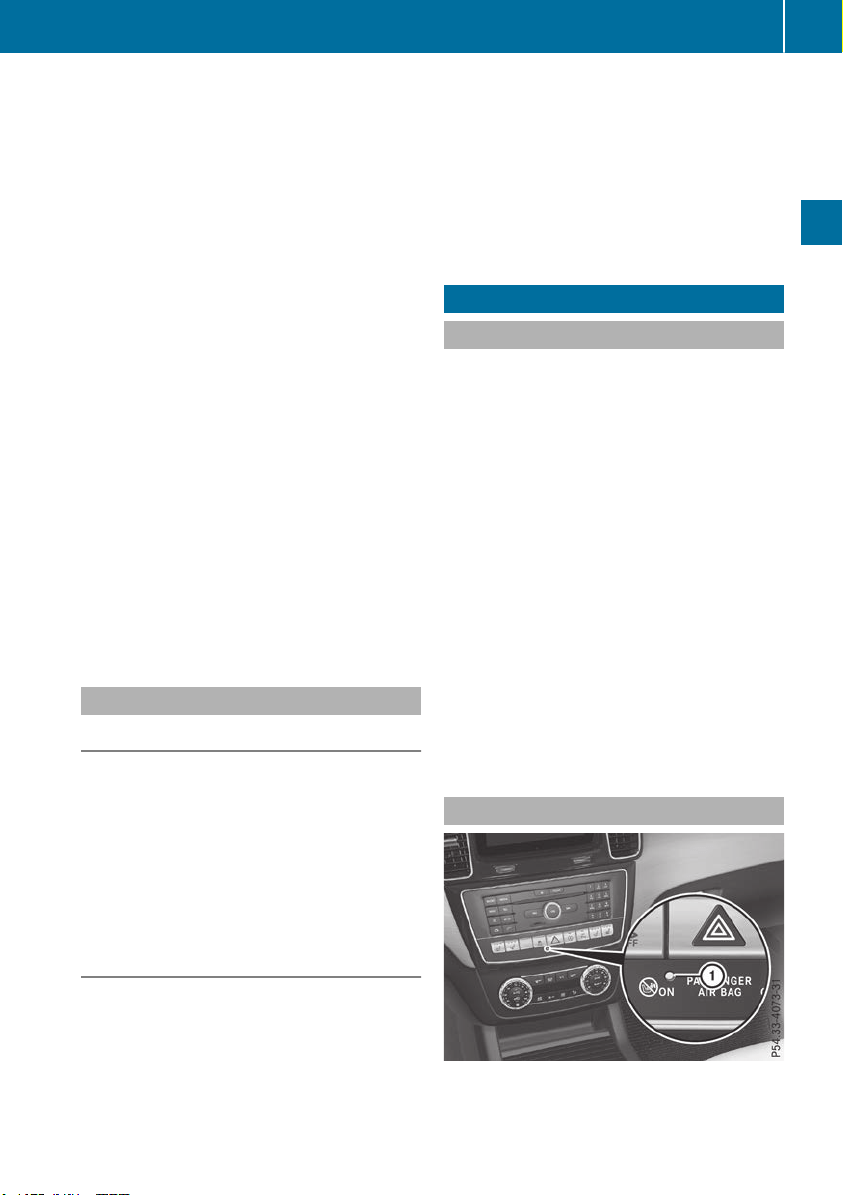
Up to a speed of approximately 44 mph
(70 km/h) the Active Brake Assist with cross-
traffic function assists you with braking in haz-
ardous situations with:
R
stationary obstacles in the path of the vehicle,
e.g. stopped or parked vehicles
R
stationary pedestrians in the path of the vehi-
cle
R
obstacles crossing your path that move in the
detection range of the sensors and are detec-
ted
X
Keep the brake pedal depressed until the
emergency braking situation is over.
ABS prevents the wheels from locking.
You can prevent the intervention of Active Brake
Assist with cross-traffic function at any time by:
R
depressing the accelerator pedal further
R
activating kickdown
R
releasing the brake pedal
The braking application of Active Brake Assist
with cross-traffic function is ended automati-
cally if:
R
you maneuver to avoid the obstacle
R
there is no longer a risk of collision
R
there is no longer an obstacle detected in
front of your vehicle
STEER CONTROL
General information
STEER CONTROL helps you by transmitting a
noticeable steering force to the steering wheel
in the direction required for vehicle stabilization.
This steering assistance is provided in particular
if:
R
both right wheels or both left wheels are on a
wet or slippery road surface when you brake
R
the vehicle starts to skid
Important safety notes
i
Observe the "Important safety notes" sec-
tion (Y page 66).
No steering assistance is provided from STEER
CONTROL, if:
R
ESP
®
is deactivated
R
ESP
®
is malfunctioning
R
the steering is malfunctioning
If ESP
®
is malfunctioning, you will be assisted
further by the electrical power steering.
Protection against theft
Immobilizer
X
To activate with the SmartKey: remove the
SmartKey from the ignition lock.
X
To activate with KEYLESS-GO: switch the
ignition off and open the driver's door.
X
To deactivate: switch on the ignition.
The immobilizer prevents your vehicle from
being started without the correct SmartKey.
When leaving the vehicle, always take the
SmartKey with you and lock the vehicle. Anyone
can start the engine if a valid SmartKey has been
left inside the vehicle.
i
The immobilizer is always deactivated when
you start the engine.
In the event that the engine cannot be started
(yet the vehicle's battery is charged), the sys-
tem is not operational. Contact an authorized
Mercedes-Benz Center or call
1-800 FOR-MERCEDES (in the USA) or
1-800-387-0100 (in Canada).
ATA (anti-theft alarm system)
Protection against theft
75
Safety
Z

X
To arm: lock the vehicle with the SmartKey or
KEYLESS-GO.
Indicator lamp : flashes. The alarm system
is armed after approximately 15 seconds.
X
To switch off using the SmartKey: unlock
the vehicle with the SmartKey.
or
X
Insert the SmartKey into the ignition lock.
X
To switch off using KEYLESS-GO: unlock
the vehicle with KEYLESS-GO.
or
X
Press the Start/Stop button on the dash-
board. The SmartKey must be inside the vehi-
cle.
A visual and audible alarm is triggered if the
alarm system is armed and you open:
R
a door
R
the vehicle with the mechanical key
R
the tailgate
R
the hood
X
To switch the alarm off with the Smart-
Key: press the % or & button on the
SmartKey.
The alarm is stopped.
or
X
Insert the SmartKey into the ignition lock.
The alarm is stopped.
X
To stop the alarm using KEYLESS-GO:
grasp the outside door handle. The SmartKey
must be outside the vehicle.
The alarm is stopped.
or
X
Press the Start/Stop button on the dash-
board. The SmartKey must be inside the vehi-
cle.
The alarm is stopped.
The alarm is not switched off, even if you close
the open door that triggered it, for example.
i If the alarm continues for more than
30 seconds, the mbrace emergency call sys-
tem automatically notifies the Customer
Assistance Center. This is done either by text
message or data connection. The emergency
call system sends the message or data provi-
ded that:
R
you have subscribed to the mbrace service.
R
the mbrace service has been activated
properly.
R
the necessary mobile phone network is
available.
76
Protection against theft
Safety
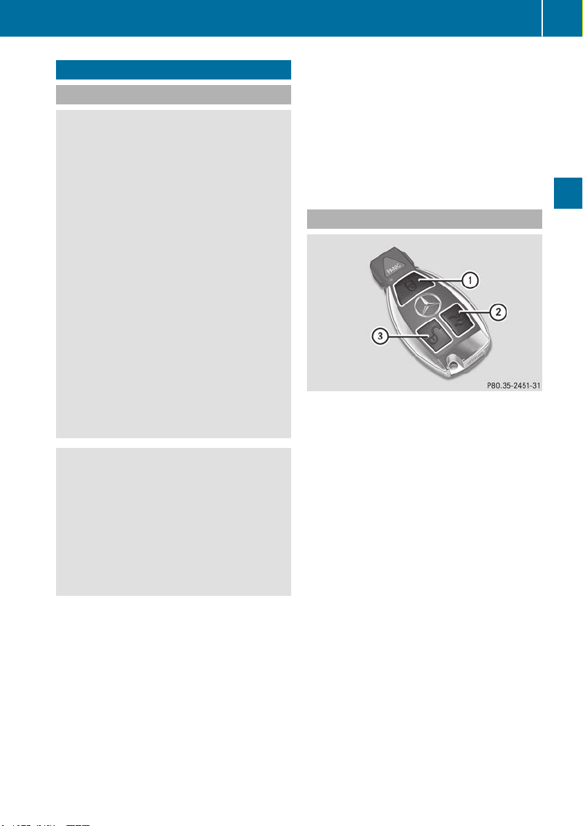
SmartKey
Important safety notes
G
WARNING
If children are left unsupervised in the vehicle,
they could:
R
open the doors, thus endangering other
people or road users.
R
get out and disrupt traffic.
R
operate the vehicle's equipment.
Additionally, children could set the vehicle in
motion if, for example, they:
R
release the parking brake.
R
shifting the automatic transmission out of
park position P
R
Start the engine.
There is a risk of an accident and injury.
When leaving the vehicle, always take the
SmartKey with you and lock the vehicle. Never
leave children or animals unattended in the
vehicle. Always keep the SmartKey out of
reach of children.
G
WARNING
If you attach heavy or large objects to the
SmartKey, the SmartKey could be uninten-
tionally turned in the ignition lock. This could
cause the engine to be switched off. There is a
risk of an accident.
Do not attach any heavy or large objects to the
SmartKey. Remove any bulky key rings before
inserting the SmartKey into the ignition lock.
!
Keep the SmartKey away from strong mag-
netic fields. Otherwise, the remote control
function could be affected.
Strong magnetic fields can occur in the vicin-
ity of powerful electrical installations.
Do not keep the SmartKey:
R
with electronic devices, e.g. a mobile phone
or another SmartKey.
R
with metallic objects, e.g. coins or metal foil.
R
inside metallic objects, e.g. a metal case.
This can affect the functionality of the Smart-
Key.
Do not keep the KEYLESS-GO or KEYLESS-GO
Start function key in the temperature-controlled
cup holder. Otherwise, the KEYLESS-GO or KEY-
LESS-GO Start function key will not be detected.
Vehicles with KEYLESS-GO start function: do
not keep the SmartKey in the cargo compart-
ment. Otherwise, the SmartKey may not be
detected, e.g. when starting the engine using
the Start/Stop button.
SmartKey functions
:
& To lock the vehicle
;
F To open/close the tailgate
=
% To unlock the vehicle
X
To unlock centrally: press the % button.
If you do not open the vehicle within approx-
imately 40 seconds of unlocking:
R
the vehicle is locked again.
R
anti-theft protection is reactivated.
X
To lock centrally: press the & button.
The SmartKey centrally locks and unlocks the
following components:
R
the doors
R
the tailgate
R
the fuel filler flap
The turn signals flash once when unlocking and
three times when locking.
You can also set an audible signal to confirm
that the vehicle has been locked. The audible
signal can be activated and deactivated using
the on-board computer (Y page 240).
You will receive visual and acoustic locking con-
firmation if all components were able to be
locked.
SmartKey
77
Opening and closing
Z
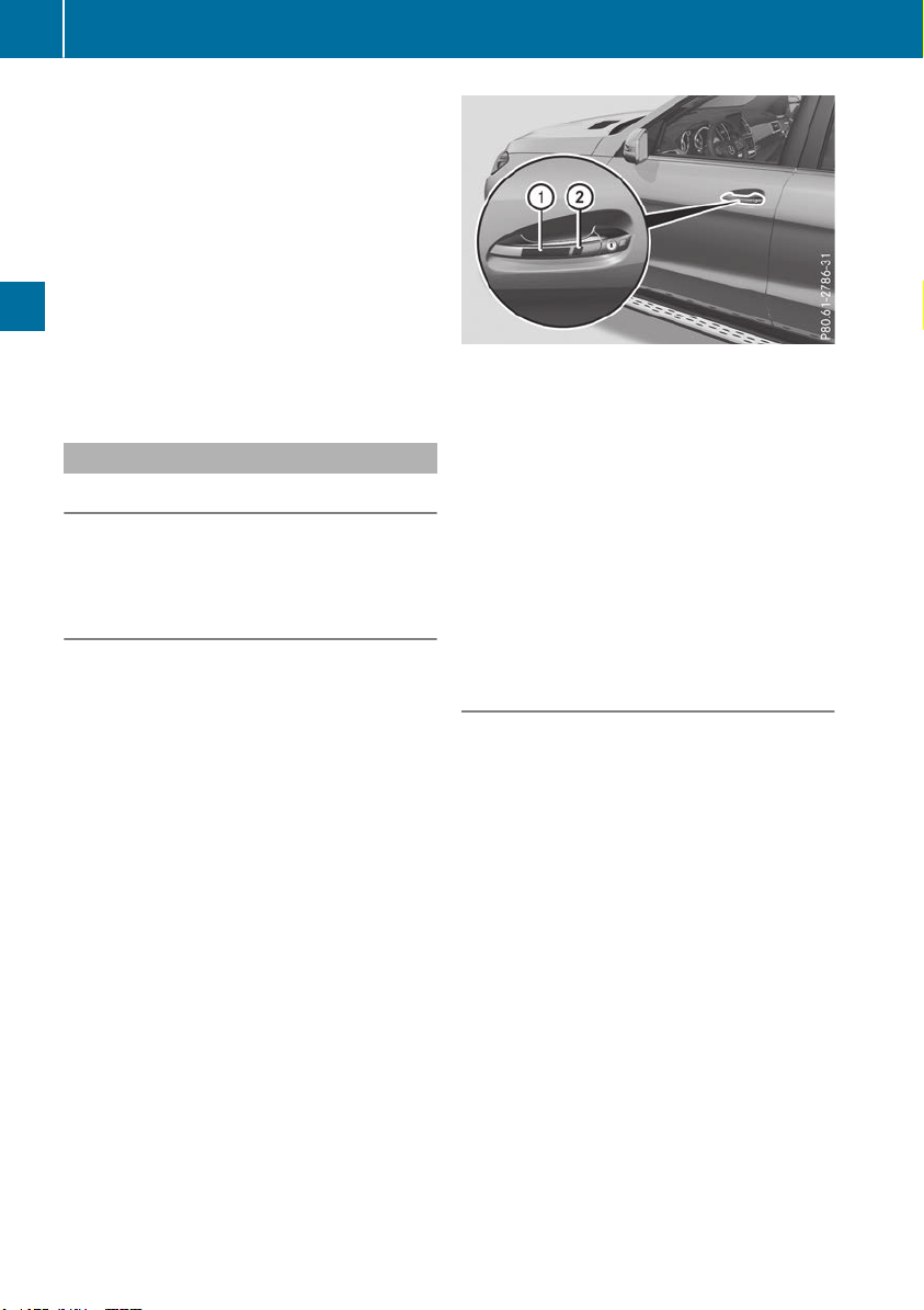
If activated in the multimedia system, the loca-
tor lighting also lights up in the dark (see the
Digital Operator's Manual).
X
To open the tailgate automatically from
outside the vehicle: press and hold the F
button until the tailgate opens.
Vehicles with KEYLESS-GO:
X
To close the tailgate automatically from
outside the vehicle: if the SmartKey is loca-
ted in the immediate vicinity of the vehicle,
press the F button on the SmartKey.
When the tailgate closes you can then release
the button.
KEYLESS-GO
General notes
Bear in mind that the engine can be started by
any of the vehicle occupants if there is a KEY-
LESS-GO key in the vehicle (Y page 137).
Locking/unlocking centrally
You can start, lock or unlock the vehicle using
KEYLESS-GO. To do this, you only need carry the
SmartKey with you. You can combine the func-
tions of KEYLESS-GO with those of a conven-
tional SmartKey. Unlock the vehicle by using
KEYLESS-GO, for instance, and lock it using the
& button on the SmartKey.
The driver's door and the door at which the han-
dle is used, must both be closed. The SmartKey
must be outside the vehicle. When locking or
unlocking with KEYLESS-GO, the distance
between the SmartKey and the corresponding
door handle must not be greater than 3 ft (1 m).
KEYLESS-GO checks whether a valid SmartKey
is in the vehicle by periodically establishing a
radio connection between the vehicle and the
SmartKey. This happens:
R
when starting the engine
R
while driving
R
when the external door handles are touched
R
during convenience closing
X
To unlock the vehicle: touch the inner sur-
face of the door handle.
X
To lock the vehicle: touch sensor surface :
or ;.
Make sure that you do not touch the inner
surface of the door handle.
X
Convenience closing feature: touch
recessed sensor surface ; for an extended
period.
Further information on the convenience closing
feature (Y page 90).
If you pull on the handle of the tailgate, only the
cargo compartment of the vehicle is unlocked.
Deactivating and activating
If you do not intend to use a SmartKey for an
extended period of time, you can deactivate the
KEYLESS-GO function of the SmartKey. The
SmartKey will then use very little power, thereby
conserving battery power. For the purposes of
activation/deactivation, the vehicle must not be
nearby.
X
To deactivate: press the & button on the
SmartKey twice in rapid succession.
The battery check lamp of the SmartKey
flashes twice briefly and lights up once, KEY-
LESS-GO is deactivated (Y page 80).
X
To activate: press any button on the Smart-
Key.
or
X
Insert the SmartKey into the ignition lock.
KEYLESS-GO and all of its associated features
are available again.
78
SmartKey
Opening and closing
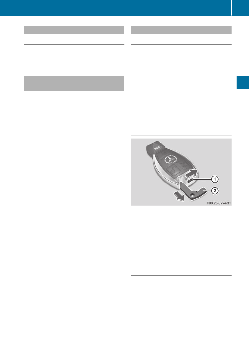
KEYLESS-GO start function
General notes
Bear in mind that the engine can be started by
any of the vehicle occupants if there is a Smart-
Key in the vehicle (Y page 137).
Changing the settings of the locking
system
You can change the settings of the locking sys-
tem. This means that only the driver's door and
the fuel filler flap are unlocked when the vehicle
is unlocked. This is useful if you frequently travel
alone.
X
To change the setting: press and hold down
the % and & buttons simultaneously
for about six seconds until the battery indica-
tor lamp flashes twice (Y page 80).
If the setting of the locking system is changed
within the signal range of the vehicle, pressing
the & or % button:
R
locks or
R
unlocks the vehicle
The SmartKey now functions as follows:
X
To unlock: press the % button once.
X
To unlock centrally: press the % button
twice.
X
To lock centrally: press the & button.
The KEYLESS-GO function is changed as fol-
lows:
X
To unlock the driver's door: touch the inner
surface of the door handle on the driver's
door.
X
To unlock centrally: touch the inner surface
of the door handle on the front-passenger
door or the rear door.
X
To lock centrally: touch the outer sensor
surface on one of the door handles
(Y page 78).
X
To restore the factory settings: press and
hold down the % and & buttons simul-
taneously for approximately six seconds until
the battery check lamp flashes twice
(Y page 80).
Mechanical key
General notes
If the vehicle can no longer be locked or
unlocked with the SmartKey or with KEYLESS-
GO, use the mechanical key.
If you use the mechanical key to unlock and
open the driver's door, the anti-theft alarm sys-
tem will be triggered. Switch off the alarm
(Y page 75).
If you unlock the vehicle using the mechanical
key, the fuel filler flap will not be unlocked auto-
matically.
X
To unlock the fuel filler flap: insert the
SmartKey into the ignition lock.
Removing the mechanical key
X
Push release catch : in the direction of the
arrow and at the same time remove mechan-
ical key ; from the SmartKey.
For further information about:
R
Unlocking the driver's door (Y page 84)
R
Unlocking the cargo compartment
(Y page 88)
R
Locking the vehicle (Y page 84)
Inserting the mechanical key
X
Push mechanical key ; completely into the
SmartKey until it engages and release
catch : is back in its basic position.
SmartKey
79
Opening and closing
Z
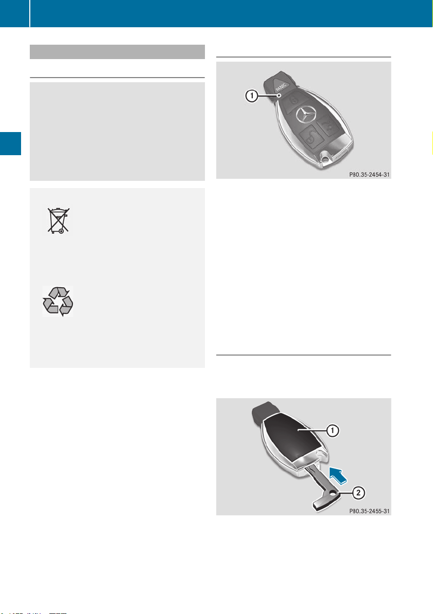
SmartKey battery
Important safety notes
G
WARNING
Batteries contain toxic and corrosive substan-
ces. If batteries are swallowed, it can result in
severe health problems. There is a risk of fatal
injury.
Keep batteries out of the reach of children. If
a battery is swallowed, seek medical attention
immediately.
H
Environmental note
Batteries contain dangerous
substances. It is against the
law to dispose of them with
the household rubbish. They
must be collected separately
and recycled to protect the
environment.
Dispose of batteries in an
environmentally friendly
manner. Take discharged
batteries to a qualified spe-
cialist workshop or a special
collection point for used bat-
teries.
The SmartKey batteries contain perchlorate
material, which may require special handling
and regard for the environment. National guide-
lines must be observed during disposal. In Cal-
ifornia, see www.dtsc.ca.gov/
HazardousWaste/Perchlorate/index.cfm.
Mercedes-Benz recommends that you have the
batteries replaced at a qualified specialist work-
shop.
Checking the battery
X
Press the & or % button.
The battery is working properly if battery
check lamp : lights up briefly.
The battery is discharged if battery check
lamp : does not light up briefly.
X
Change the battery (Y page 80).
If the SmartKey battery is checked within the
signal reception range of the vehicle, pressing
the & or % button:
R
locks or
R
unlocks the vehicle
i
You can get a battery at any qualified spe-
cialist workshop.
Replacing the battery
You require a CR 2025 3 V cell battery.
X
Take the mechanical key out of the SmartKey
(Y page 79).
X
Press mechanical key ; into the SmartKey
opening in the direction of the arrow until bat-
tery compartment cover : opens. Do not
hold battery compartment cover : closed
while doing so.
X
Remove battery compartment cover :.
80
SmartKey
Opening and closing
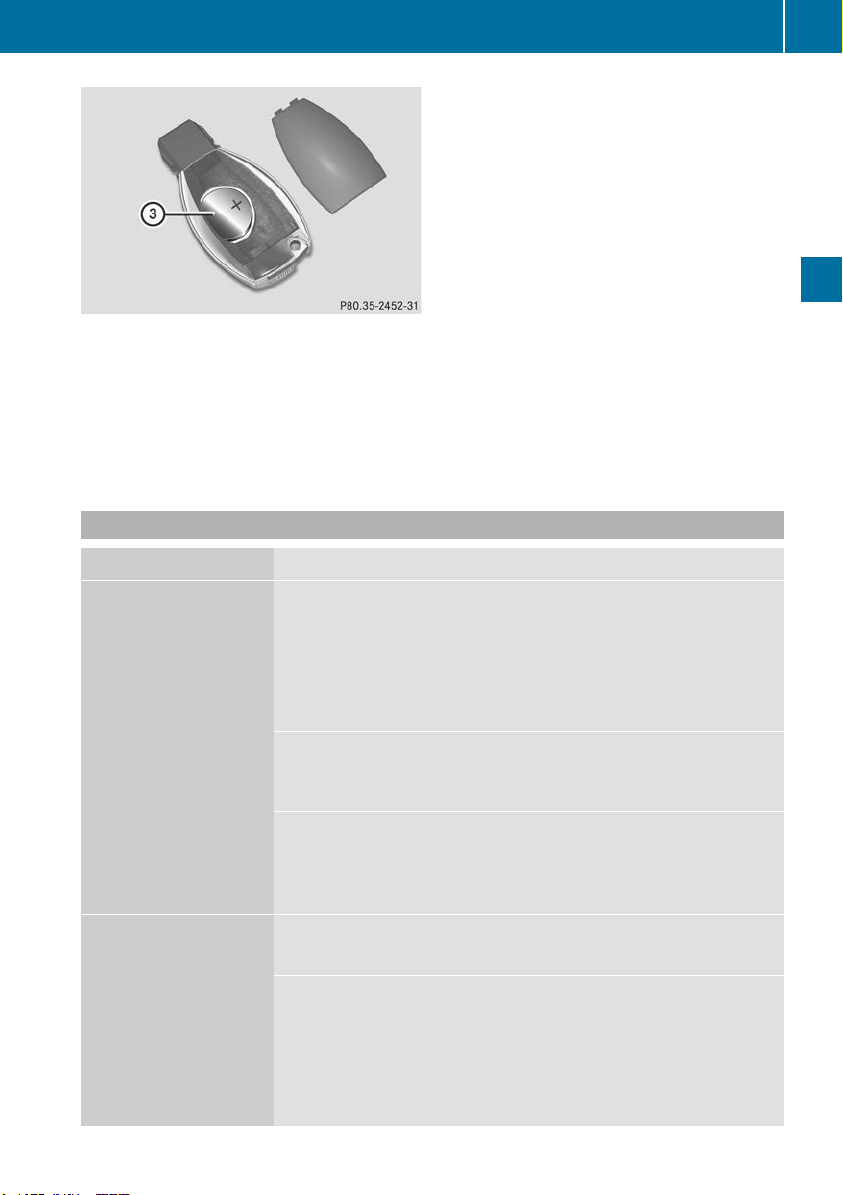
X
Repeatedly tap the SmartKey against your
palm until battery = falls out.
X
Insert the new battery with the positive ter-
minal facing upwards. Use a lint-free cloth to
do so.
X
Make sure that the surface of the battery is
free of lint, grease and other contaminants.
X
Insert the front tabs of battery compartment
cover : into the housing first and then press
to close it.
X
Insert mechanical key ; into the SmartKey
(Y page 79).
X
Check the function of all SmartKey buttons on
the vehicle.
Problems with the SmartKey
Problem
Possible causes/consequences and MM Solutions
You can no longer lock or
unlock the vehicle using
the SmartKey.
The SmartKey battery is discharged or nearly discharged.
X
Check the SmartKey battery (Y page 80) and replace it if necessary
(Y page 80).
If this does not work:
X
Unlock (Y page 84) or lock (Y page 84) the vehicle using the
mechanical key.
There is interference from a powerful source of radio waves.
X
Unlock (Y page 84) or lock (Y page 84) the vehicle using the
mechanical key.
The SmartKey is faulty.
X
Unlock (Y page 84) or lock (Y page 84) the vehicle using the
mechanical key.
X
Have the SmartKey checked at a qualified specialist workshop.
You can no longer lock or
unlock the vehicle using
KEYLESS-GO.
KEYLESS-GO was deactivated.
X
Reactivate KEYLESS-GO (Y page 78).
The SmartKey battery is discharged or nearly discharged.
X
Check the SmartKey battery (Y page 80) and replace it if necessary
(Y page 80).
If this does not work:
X
Unlock (Y page 84) or lock (Y page 84) the vehicle using the
mechanical key.
SmartKey
81
Opening and closing
Z

Problem
Possible causes/consequences and MM Solutions
There is interference from a powerful source of radio waves.
X
Unlock (Y page 84) or lock (Y page 84) the vehicle using the
mechanical key.
KEYLESS-GO is malfunctioning.
X
Lock/unlock the vehicle using the remote control function of the
SmartKey.
X
Have the vehicle and SmartKey checked at a qualified specialist
workshop.
If the vehicle can also not be locked/unlocked using the remote con-
trol function:
X
Unlock (Y page 84) or lock (Y page 84) the vehicle using the
mechanical key.
X
Have the vehicle and SmartKey checked at a qualified specialist
workshop.
The engine cannot be
started using the Smart-
Key.
The on-board voltage is too low.
X
Switch off non-essential consumers, e.g. seat heating or interior
lighting, and try to start the engine again.
If this does not work:
X
Check the starter battery and charge it if necessary (Y page 342).
or
X
Jump-start the vehicle (Y page 343).
or
X
Consult a qualified specialist workshop.
The engine cannot be
started using the Start/
Stop button. The Smart-
Key is in the vehicle.
The vehicle is locked.
X
Unlock the vehicle and try to start the vehicle again.
The SmartKey battery is discharged or nearly discharged.
X
Check the SmartKey battery (Y page 80) and replace it if necessary
(Y page 80).
If this does not work:
X
Start your vehicle with the SmartKey in the ignition lock.
There is interference from a powerful source of radio waves.
X
Start your vehicle with the SmartKey in the ignition lock.
You have lost a Smart-
Key.
X
Have the SmartKey deactivated at a qualified specialist workshop.
X
Report the loss immediately to the vehicle insurers.
X
If necessary, have the locks changed as well.
You have lost the
mechanical key.
X
Report the loss immediately to the vehicle insurers.
X
If necessary, have the locks changed as well.
82
SmartKey
Opening and closing
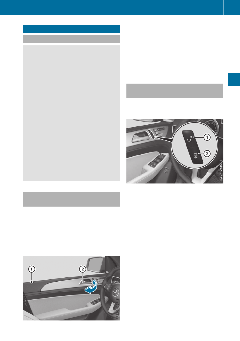
Doors
Important safety notes
G
WARNING
If children are left unsupervised in the vehicle,
they could:
R
open the doors, thus endangering other
people or road users.
R
get out and disrupt traffic.
R
operate the vehicle's equipment.
Additionally, children could set the vehicle in
motion if, for example, they:
R
release the parking brake.
R
shifting the automatic transmission out of
park position P
R
Start the engine.
There is a risk of an accident and injury.
When leaving the vehicle, always take the
SmartKey with you and lock the vehicle. Never
leave children or animals unattended in the
vehicle. Always keep the SmartKey out of
reach of children.
Unlocking and opening doors from
the inside
You can open a door from inside the vehicle
even if it has been locked. You can only open the
rear doors from inside the vehicle if they are not
secured by the child-proof locks (Y page 65).
If the vehicle has previously been locked from
the outside, opening a door from the inside will
trigger the anti-theft alarm system. Switch off
the alarm (Y page 75).
X
Front door: pull door handle ;.
If the door is locked, locking knob : pops up.
The door is unlocked and can be opened.
X
Rear door: pull door handle ;.
If the door is locked, locking knob : pops up
and the door unlocks.
X
Pull door handle ; again.
The door can be opened.
Centrally locking and unlocking the
vehicle from the inside
You can centrally lock or unlock the vehicle from
the inside. The buttons are located on both front
doors.
X
To unlock: press button :.
X
To lock: press button ;.
If the front-passenger door is closed, the vehi-
cle locks.
Meanwhile, the fuel filler flap will not be locked
or unlocked.
You cannot unlock the vehicle centrally from the
inside if the vehicle has been locked from the
outside.
You can open a front door from inside the vehi-
cle even if it has been locked.
If a locked door is opened from the inside, the
previous unlock status of the vehicle will be
taken into consideration if:
R
the vehicle was locked using the locking but-
ton for the central locking, or
R
if the vehicle was locked automatically
The vehicle will be fully unlocked if it had previ-
ously been fully unlocked. If only the driver's
door had been previously unlocked, only the
door which has been opened from the inside is
unlocked.
Doors
83
Opening and closing
Z
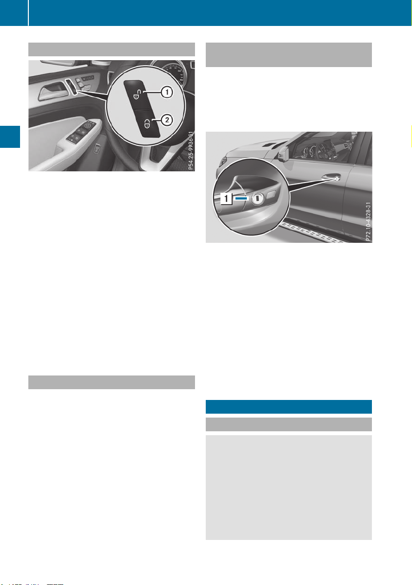
Automatic locking feature
X
To deactivate: press and hold button : for
about five seconds until a tone sounds.
X
To activate: press and hold button ; for
about five seconds until a tone sounds.
If you press one of the two buttons and do not
hear a tone, the relevant setting has already
been selected.
The vehicle is locked automatically when the
ignition is switched on and the wheels are turn-
ing.
You could therefore be locked out if:
R
the vehicle is being pushed.
R
the vehicle is being towed.
R
the vehicle is on a roller dynamometer.
You can also switch the automatic locking func-
tion on and off using the on-board computer
(Y page 240).
Power closing
Power closing pulls the doors and tailgate into
their locks automatically even if they are not
completely closed.
X
To power close a door: push the door into
the lock up to the first detent position.
Power closing will pull the door fully closed.
X
To power close the tailgate: lightly press
the tailgate downwards.
Power closing will pull the tailgate fully
closed.
Unlocking/locking the driver's door
using the mechanical key
i
If you want to centrally lock the vehicle using
the mechanical key, begin by pressing the
locking button for the interior locking mech-
anism while the driver's door is open. Then
proceed to lock the driver's door using the
mechanical key.
X
Insert the mechanical key into the lock of the
driver's door as far as it will go.
X
To unlock: turn the mechanical key counter-
clockwise to position 1.
X
To lock: turn the mechanical key clockwise as
far as it will go to position 1.
If you use the mechanical key to unlock and
open the driver's door, the anti-theft alarm sys-
tem will be triggered. Switch off the alarm
(Y page 75).
If you lock the vehicle as described above, the
fuel filler flap is not locked. The anti-theft alarm
system is not armed.
Cargo compartment
Important safety notes
G
WARNING
Combustion engines emit poisonous exhaust
gases such as carbon monoxide. If the tailgate
is open when the engine is running, particu-
larly if the vehicle is moving, exhaust fumes
could enter the passenger compartment.
There is a risk of poisoning.
Turn off the engine before opening the tail-
gate. Never drive with the tailgate open.
84
Cargo compartment
Opening and closing
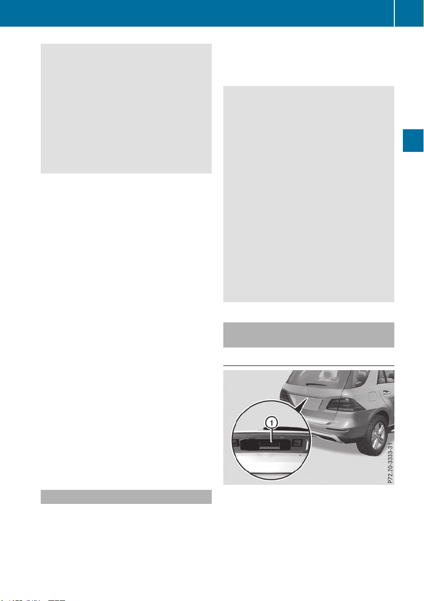
G
WARNING
If objects, luggage or loads are not secured or
not secured sufficiently, they could slip, tip
over or be flung around and thereby hit vehicle
occupants. There is a risk of injury, particu-
larly in the event of sudden braking or a sud-
den change in direction.
Always store objects so that they cannot be
flung around. Secure objects, luggage or
loads against slipping or tipping before the
journey.
!
The tailgate swings upwards and to the rear
when opened. Therefore, make sure that
there is sufficient clearance above and behind
the tailgate.
The opening dimensions of the tailgate can be
found in the "Vehicle data" section
(Y page 390).
You should preferably place luggage or loads in
the cargo compartment. Observe the loading
guidelines (Y page 295).
Do not leave the SmartKey in the cargo com-
partment. You could otherwise lock yourself
out.
Vehicles without the EASY-PACK tailgate:
the tailgate can be:
R
opened and closed manually from outside
R
unlocked from inside with the emergency
release
For vehicles with the EASY-PACK tailgate:
you can:
R
close the tailgate manually from outside
R
open the tailgate automatically from outside
R
open and close the tailgate automatically
from inside
R
unlock the tailgate from inside with the emer-
gency release
R
limit the opening angle of the tailgate
Tailgate reversing feature
On vehicles with the tailgate remote closing fea-
ture, the tailgate is equipped with automatic
obstacle recognition with a reversing feature. If
a solid object blocks or restricts the tailgate
when automatically opening or closing, this pro-
cedure is stopped. If the tailgate is stopped dur-
ing the closing procedure, it will open again
automatically. The automatic obstacle recogni-
tion with reversing feature is only an aid. It is not
a substitute for your attentiveness when open-
ing and closing the tailgate.
G
WARNING
The reversing feature does not respond:
R
to soft, light and thin objects, e.g. fingers
R
over the last Ó in (8 mm) of the closing
movement
The reversing feature cannot prevent some-
one from becoming trapped in these situa-
tions in particular. There is a risk of injury.
Make sure that no body parts are in close
proximity during the closing procedure.
If somebody becomes trapped:
R
press the F button on the SmartKey, or
R
pull or press the remote operating switch
on the driver's door or
R
press the closing or locking button on the
tailgate or
R
pull the handle on the tailgate
Opening and closing manually from
outside
Opening
X
Press the % button on the SmartKey.
X
Pull handle :.
X
Raise the tailgate.
Vehicles with the EASY-PACK tailgate: if you
pull handle : and then release it, the tailgate
opens automatically.
Cargo compartment
85
Opening and closing
Z
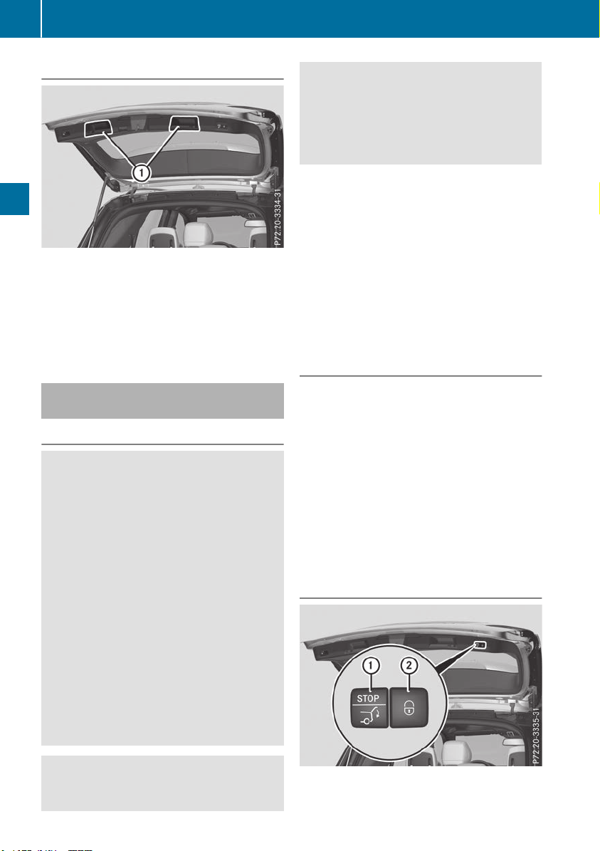
Closing
X
Pull the tailgate down using recess :.
X
Allow the tailgate to drop into the lock.
X
Lock the vehicle if necessary with the &
button on the SmartKey or with KEYLESS-GO.
i
If a KEYLESS-GO key is detected in the cargo
compartment, the tailgate will not lock.
Opening/closing automatically from
the outside
Important safety notes
G
WARNING
Parts of the body could become trapped dur-
ing automatic closing of the tailgate. More-
over, people, e.g. children, may be standing in
the closing area or may enter the closing area
during the closing process. There is a risk of
injury.
Make sure that nobody is in the vicinity of the
closing area during the closing process.
Use one of the following options to stop the
closing process:
R
press the F button on the SmartKey.
R
pull or press the remote operating switch
on the driver's door.
R
press the closing or locking button on the
tailgate.
R
pull the handle on the tailgate
G
WARNING
Combustion engines emit poisonous exhaust
gases such as carbon monoxide. If the tailgate
is open when the engine is running, particu-
larly if the vehicle is moving, exhaust fumes
could enter the passenger compartment.
There is a risk of poisoning.
Turn off the engine before opening the tail-
gate. Never drive with the tailgate open.
!
The tailgate swings upwards and to the rear
when opened. Therefore, make sure that
there is sufficient clearance above and behind
the tailgate.
Two warning tones sound while the tailgate is
opening or closing.
The opening dimensions of the tailgate can be
found in the "Vehicle data" section
(Y page 390).
i
Notes on the automatic reversing feature for
the tailgate (Y page 85).
Opening the tailgate automatically
You can open the tailgate automatically with the
SmartKey or the handle in the tailgate.
X
Press and hold the F button on the Smart-
Key until the tailgate opens.
or
X
When the tailgate is unlocked, pull the tailgate
handle and let it go again immediately.
or
X
With the tailgate stopped in an intermediate
position, pull the tailgate upwards.
You can release the tailgate as soon as the
tailgate starts to open.
Closing the tailgate automatically
86
Cargo compartment
Opening and closing
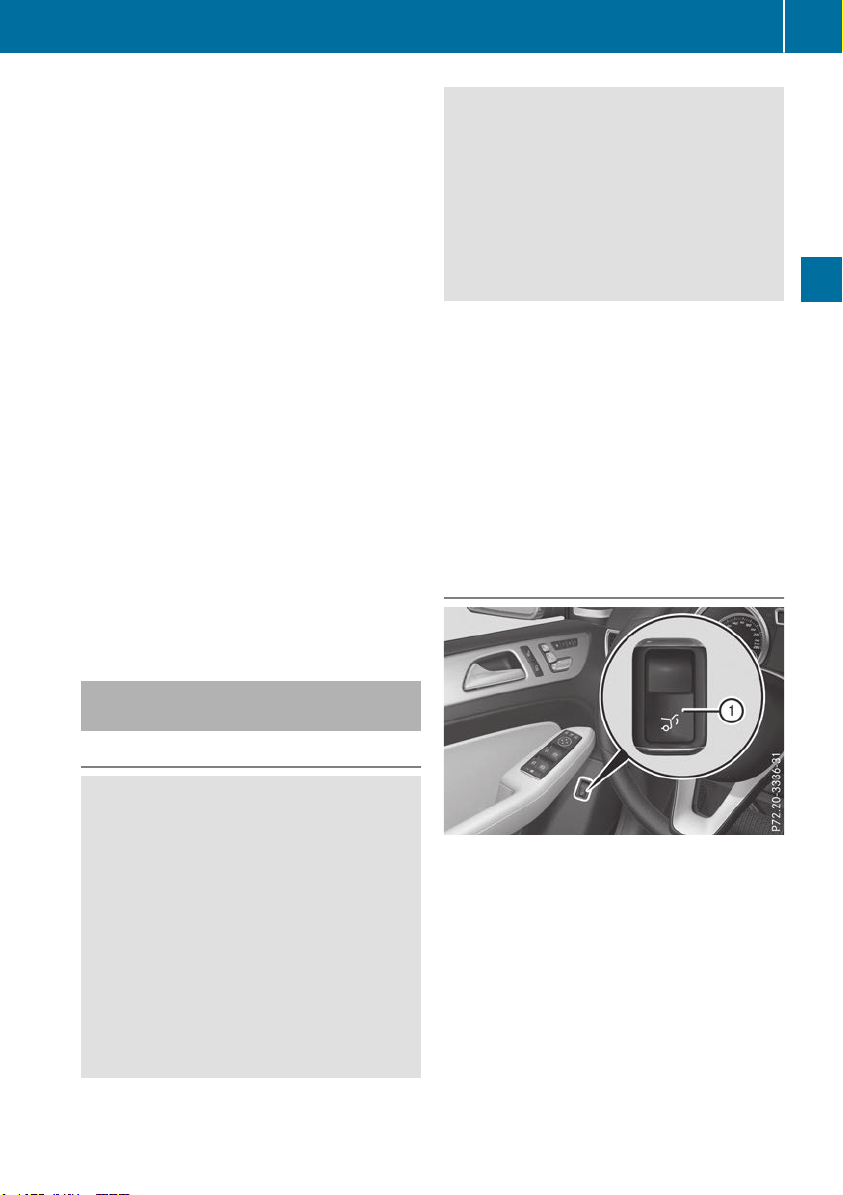
X
To close: press closing button : in the tail-
gate.
or
X
Vehicles with KEYLESS-GO or KEYLESS-GO
starting function: press and hold the F
button on the SmartKey until the tailgate
closes.
You can release the button as soon as the
tailgate starts to close.
Vehicles with KEYLESS-GO or KEYLESS-GO
starting function: you can close and lock the
tailgate simultaneously.
X
Press locking button ; in the tailgate.
If a KEYLESS-GO or KEYLESS-GO starting
function key is detected outside the vehicle,
the tailgate closes and locks. All the doors
must be shut and the SmartKey located in the
vicinity of the tailgate.
i
The tailgate cannot be opened and closed
with the SmartKey if there is a SmartKey in the
ignition.
If the tailgate touches an object while closing,
the closing procedure is interrupted and the
tailgate reopens.
If a KEYLESS-GO or KEYLESS-GO starting
function key is detected in the cargo com-
partment, the tailgate will not lock.
Opening/closing automatically from
inside
Important safety notes
G
WARNING
Parts of the body could become trapped dur-
ing automatic closing of the tailgate. In addi-
tion, people may be standing in the closing
area or may enter the closing area, e.g. chil-
dren, during the closing procedure. There is a
risk of injury.
Make sure that nobody is in the vicinity of the
closing area during the closing process.
Release the remote operating switch imme-
diately if somebody becomes trapped. To re-
open the tailgate pull on the remote operating
switch.
G
WARNING
Combustion engines emit poisonous exhaust
gases such as carbon monoxide. If the tailgate
is open when the engine is running, particu-
larly if the vehicle is moving, exhaust fumes
could enter the passenger compartment.
There is a risk of poisoning.
Turn off the engine before opening the tail-
gate. Never drive with the tailgate open.
!
The tailgate swings upwards and to the rear
when opened. Therefore, make sure that
there is sufficient clearance above and behind
the tailgate.
Two warning tones sound while the tailgate is
opening or closing.
The opening dimensions of the tailgate can be
found in the "Vehicle data" section
(Y page 390).
i
Notes on the automatic reversing feature for
the tailgate (Y page 85).
Opening and closing
X
To open: pull remote operating switch : for
the tailgate until the tailgate opens.
X
To close: turn the SmartKey to position 1 or
2 in the ignition lock.
X
Press remote operating switch for tailgate :
until the tailgate is completely closed.
You can open and close the tailgate from the
driver's seat when the vehicle is stationary and
unlocked.
Cargo compartment
87
Opening and closing
Z
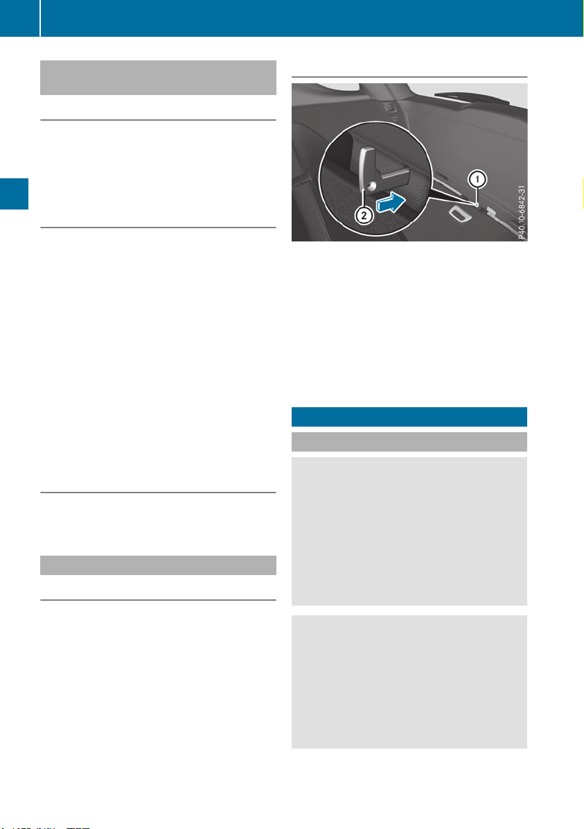
Limiting the opening angle of the tail-
gate
General notes
!
Make sure there is sufficient clearance to
open the tailgate fully when setting the open-
ing angle. The tailgate could otherwise be
damaged. Ideally, set the opening angle out-
side.
Activating
You can limit the opening angle of the tailgate.
This is possible in the top half of its opening
range, up to approximately 4 in (10 cm) before
the stop.
X
To open the tailgate: pull the handle on the
tailgate.
X
To stop the opening procedure at the
desired position: press the closing button in
the tailgate or pull the handle on the outside
of the tailgate again.
X
To save the position: press and hold the
closing button in the tailgate until two short
tones sound.
The opening angle limiter is activated. The
tailgate will now stop in the stored position
when opening.
Deactivating
X
Press and hold the closing button in the tail-
gate until you hear a short tone.
Tailgate emergency release
General notes
!
The tailgate swings upwards and to the rear
when opened. Therefore, make sure that
there is sufficient clearance above and behind
the tailgate.
The opening dimensions of the tailgate can be
found in the "Vehicle data" section
(Y page 390).
If the tailgate can no longer be unlocked:
R
using the SmartKey, or
R
using the remote operating switch in the door
control panel:
Use the emergency release.
Opening
X
Take mechanical key ; out of the SmartKey
(Y page 79).
X
Insert mechanical key ; or a suitable tool,
e.g. a thin screwdriver, into opening : in the
paneling and push it in.
The tailgate is released.
X
Open the tailgate.
X
Insert mechanical key ; into the SmartKey
(Y page 79).
Side windows
Important safety notes
G
WARNING
While opening the side windows, body parts
could become trapped between the side win-
dow and the door frame as the side window
moves. There is a risk of injury.
Make sure that nobody touches the side win-
dow during the opening procedure. If some-
body becomes trapped, release the switch or
pull the switch to close the side window again.
G
WARNING
While closing the side windows, body parts in
the closing area could become trapped. There
is a risk of injury.
When closing make sure that no parts of the
body are in the closing area. If somebody
becomes trapped, release the switch or press
the switch to open the side window again.
88
Side windows
Opening and closing

G
WARNING
If children operate the side windows they
could become trapped, particularly if they are
left unsupervised. There is a risk of injury.
Activate the override feature for the rear side
windows. When leaving the vehicle, always
take the SmartKey with you and lock the vehi-
cle. Never leave children unsupervised in the
vehicle.
Side window reversing feature
The side windows are equipped with an auto-
matic reversing feature. If a solid object blocks
or restricts a side window during the closing
process, the side window opens again automat-
ically. However, the automatic reversing feature
is only an aid and does not relieve you of the
responsibility of paying attention when closing a
side window.
G
WARNING
The reversing feature does not react:
R
to soft, light and thin objects, e.g. small fin-
gers
R
over the last 1/6 in(4 mm) of the closing
movement
R
during resetting
R
when closing the side window again man-
ually immediately after automatic reversing
This means that the reversing feature cannot
prevent someone being trapped in these sit-
uations. There is a risk of injury.
Make sure that no body parts are in close
proximity during the closing procedure. If
someone becomes trapped, press the switch
to open the side window again.
Opening and closing the side win-
dows
The switches for all side windows are located on
the driver's door. There is also a switch on each
door for the corresponding side window.
The switches on the driver's door take prece-
dence.
:
Front left
;
Front right
=
Rear right
?
Rear left
X
Turn the SmartKey to position 1 or 2 in the
ignition lock.
X
To open manually: press and hold the cor-
responding switch.
X
To open fully: press the switch beyond the
pressure point and release it.
Automatic operation is started.
X
To close manually: pull the corresponding
switch and hold it.
X
To close fully: pull the switch beyond the
pressure point and release it.
Automatic operation is started.
X
To interrupt automatic operation: press/
pull the corresponding switch again.
If you press the switch beyond the pressure
point and release, automatic operation is star-
ted in the corresponding direction. You can stop
automatic operation by pressing/pulling the
switch again.
You can continue to operate the side windows
after you switch off the engine or remove the
SmartKey. This function is available for up to five
minutes or until the driver's or front-passenger
door is opened.
The side windows cannot be operated from the
rear when the override feature for the side win-
dows is activated (Y page 65).
Convenience opening
General notes
Vehicles with KEYLESS-GO or KEYLESS-GO
start function: you can ventilate the vehicle
before you start driving.
Side windows
89
Opening and closing
Z

To do this, the SmartKey is used to carry out the
following functions simultaneously:
R
unlock the vehicle
R
open the side windows
R
open the sliding sunroof or the panorama roof
with power tilt/sliding panel and the roller
sunblinds
R
switch on the seat ventilation for the driver's
seat
The convenience opening feature can only be
operated using the SmartKey. The SmartKey
must be close to the vehicle. For vehicles with-
out KEYLESS-GO, the SmartKey must be near
the driver's door handle.
The "convenience opening" feature is also avail-
able when the vehicle is unlocked.
Convenience opening
X
Vehicles without KEYLESS-GO: point the tip
of the SmartKey at the door handle on the
driver's door.
X
Press and hold the % button until the side
windows and the sliding sunroof or panorama
roof with power tilt/sliding panel are in the
desired position.
If the roller sunblinds of the panorama roof
with power tilt/sliding panel are closed, the
roller sunblinds are opened first.
X
Press and hold the % button again until the
panorama roof with power tilt/sliding panel is
in the desired position.
X
To interrupt convenience opening: release
the % button.
Convenience closing feature
Important safety notes
G
WARNING
When the convenience closing feature is oper-
ating, parts of the body could become trapped
in the closing area of the side window and the
sliding sunroof. There is a risk of injury.
Observe the complete closing procedure
when the convenience closing feature is oper-
ating. Make sure that no body parts are in
close proximity during the closing procedure.
When you lock the vehicle, you can simultane-
ously:
R
close the side windows
R
close the sliding sunroof or the panorama roof
with power tilt/sliding panel
On vehicles with a panorama roof with power
tilt/sliding panel, you can then close the roller
sunblinds.
Proceed as follows if someone is trapped:
R
Release the & button to interrupt the clos-
ing procedure.
R
Press and hold the % button to open.
Vehicles with KEYLESS-GO:
R
Release the sensor surfaces on the exterior
door handle to interrupt the closing proce-
dure.
R
To open, pull the same door handle immedi-
ately and hold it firmly. The side windows and
the sliding sunroof will open for as long as the
door handle is held but the door is not
opened.
Notes on the automatic reversing feature for:
R
The side window (Y page 89)
R
The sliding sunroof (Y page 93)
R
The panorama roof with power tilt/sliding
panel (Y page 93)
Using the SmartKey
The SmartKey must be close to the vehicle. For
vehicles without KEYLESS-GO, the SmartKey
must be near the driver's door handle.
X
Vehicles without KEYLESS-GO: point the tip
of the SmartKey at the door handle on the
driver's door.
X
Press and hold the & button until the side
windows and the sliding sunroof or the pano-
rama roof with power tilt/sliding panel are
fully closed.
X
Make sure that all the side windows and the
sliding sunroof or panorama roof with power
tilt/sliding panel are closed.
On vehicles with a panorama roof with power
tilt/sliding panel:
X
Press and hold the & button again until the
roller sunblinds of the panorama roof with
power tilt/sliding panel close.
X
To interrupt convenience closing: release
the & button.
90
Side windows
Opening and closing
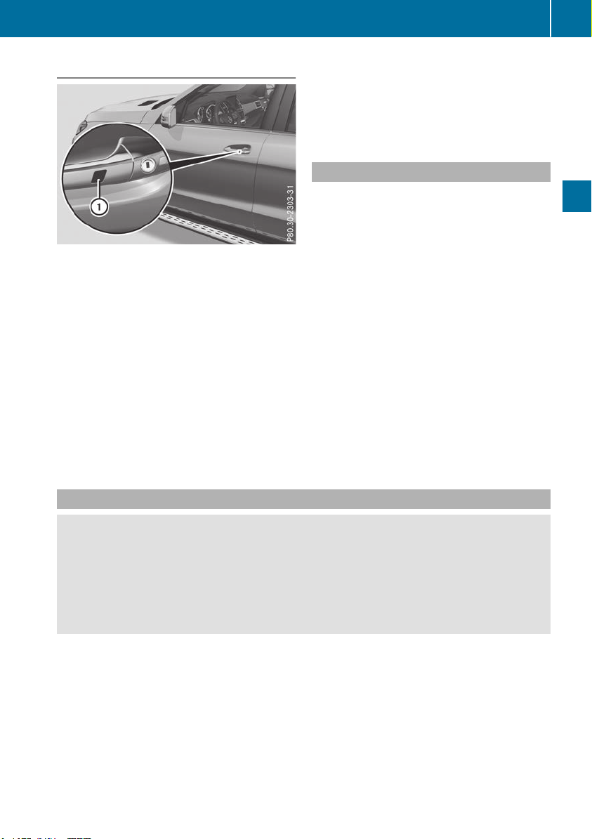
Using KEYLESS-GO
X
Touch recessed sensor surface : on the
door handle until the side windows and the
sliding sunroof or the panorama roof with
power tilt/sliding panel are fully closed.
i
Make sure you only touch recessed sensor
surface :.
X
Make sure that all the side windows and the
sliding sunroof or panorama roof with power
tilt/sliding panel are closed.
X
Vehicles with a panorama roof with
power tilt/sliding panel: touch recessed
sensor surface : on the door handle again
until the roller sunblinds of the panorama roof
with power tilt/sliding panel close.
X
To interrupt convenience closing: release
recessed sensor surface : on the door han-
dle.
Resetting the side windows
If a side window can no longer be closed fully,
you must reset it.
X
Close all the doors.
X
Turn the SmartKey to position 1 or 2 in the
ignition lock.
X
Pull the corresponding switch on the door
control panel until the side window is com-
pletely closed (Y page 89).
X
Hold the switch for an additional second.
If the side window opens again slightly:
X
Immediately pull the corresponding switch on
the door control panel until the side window is
completely closed (Y page 89).
X
Hold the switch for an additional second.
X
If the respective side window remains closed
after the button is released, then it has been
set correctly. If this is not the case, repeat the
steps above.
Problems with the side windows
G
WARNING
If you close a side window again immediately after it has been blocked or reset, the side window
closes with increased or maximum force. The reversing feature is then not active. Parts of the
body could be trapped in the closing area in the process. This poses an increased risk of injury or
even fatal injury.
Make sure that no parts of the body are in the closing area. To stop the closing process, release
the switch or push the switch again to reopen the side window.
Side windows
91
Opening and closing
Z

Problem
Possible causes/consequences and MM Solutions
A side window cannot be
closed because it is
blocked by objects, e.g.
leaves in the window
guide.
X
Remove the objects.
X
Close the side window.
A side window cannot be
closed and you cannot
see the cause.
If a side window is obstructed during closing and reopens again
slightly:
X
Immediately after the window blocks, pull the corresponding switch
again until the side window has closed.
The side window is closed with increased force.
If a side window is obstructed again during closing and reopens again
slightly:
X
Immediately after the window blocks, pull the corresponding switch
again until the side window has closed.
The side window is closed without the automatic reversing feature.
The side windows cannot
be opened or closed with
convenience opening.
The SmartKey battery is discharged or nearly discharged.
X
Check the SmartKey battery (Y page 80) and replace it if necessary
(Y page 80).
If a side window will still not open or close due to a malfunction, consult a qualified specialist
workshop.
Sliding sunroof
Important safety notes
Your vehicle may be equipped with a sliding
sunroof or a panorama roof with power tilt/slid-
ing panel. In the following section, the term
"sliding sunroof" refers to both sliding sunroof
variants.
G
WARNING
While opening and closing the sliding sunroof,
body parts in close proximity could become
trapped. There is a risk of injury.
Make sure that no body parts are in close
proximity during the opening and closing pro-
cedures.
If somebody becomes trapped:
R
release the switch immediately, or
R
during automatic operation, push the
switch briefly in any direction
The opening or closing procedure will be stop-
ped.
G
WARNING
If children operate the sliding sunroof they
could become trapped, particularly if they are
left unsupervised. There is a risk of injury.
When leaving the vehicle, always take the
SmartKey with you and lock the vehicle. Never
leave children unsupervised in the vehicle.
!
Only open the sliding sunroof if it is free of
snow and ice. Otherwise, malfunctions may
occur.
Do not allow anything to protrude from the
sliding sunroof. Otherwise, the seals could be
damaged.
!
The weather can change abruptly. It could
start to rain or snow. Make sure that the slid-
ing sunroof is closed when you leave the vehi-
cle. The vehicle electronics can be damaged if
water enters the vehicle interior.
Resonance noises can occur in addition to the
usual airflow noises when the sliding sunroof is
open. They are caused by minor pressure fluc-
tuations in the vehicle interior. Change the posi-
92
Sliding sunroof
Opening and closing
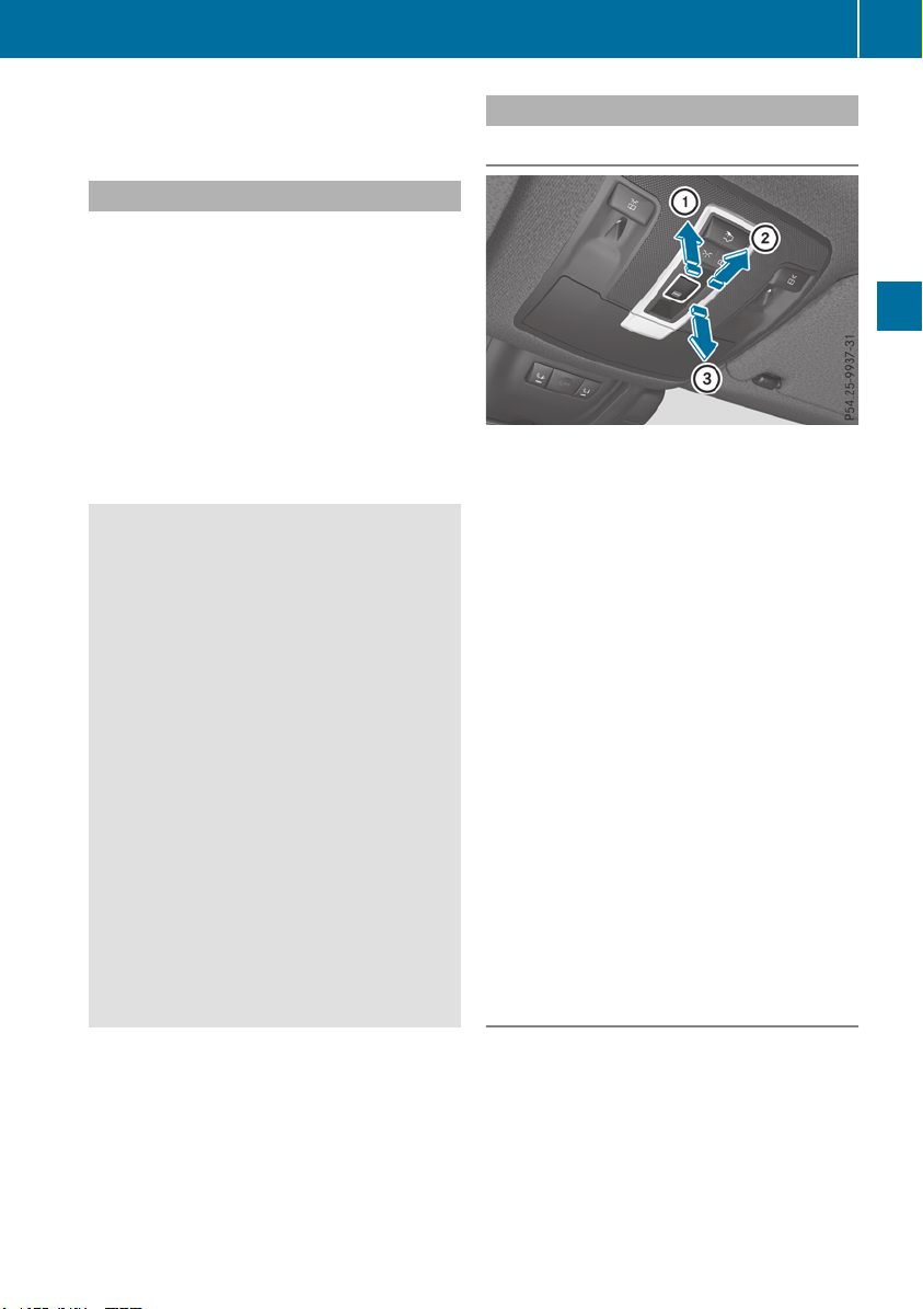
tion of the sliding sunroof or open a side win-
dow. The noise will be reduced or eliminated.
Sliding sunroof reversing feature
Your vehicle may be equipped with a sliding
sunroof or a panorama roof with power tilt/slid-
ing panel. In the following section, the term
"sliding sunroof" refers to both sliding sunroof
variants.
The sliding sunroof is equipped with an auto-
matic reversing feature. If a solid object blocks
or restricts the sliding sunroof during the closing
process, the sliding sunroof opens again auto-
matically. However, the automatic reversing
feature is only an aid and does not relieve you of
the responsibility of paying attention when clos-
ing the sliding sunroof.
G
WARNING
The reversing feature does not react:
R
to soft, light and thin objects, e.g. small fin-
gers
R
over the last 1/6 in (4 mm) of the closing
movement
R
during resetting
R
when closing the sliding sunroof again man-
ually immediately after automatic reversing
This means that the reversing feature cannot
prevent someone being trapped in these sit-
uations. There is a risk of injury.
Make sure that no body parts are in close
proximity during the closing procedure.
If somebody becomes trapped:
R
release the switch immediately, or
R
press the switch in any direction during the
automatic closing process
The closing process is stopped.
Operating the sliding sunroof
Opening and closing
:
To raise
;
To open
=
To close/lower
X
Turn the SmartKey to position 1 or 2 in the
ignition lock.
X
Press or pull the 2 switch in the corre-
sponding direction.
If you press the 2 switch beyond the pres-
sure point, an automatic opening/closing proc-
ess is started in the corresponding direction.
You can stop automatic operation by pressing/
pulling the switch again.
When opening and raising the roof, automatic
operation is only available if the sliding sunroof
is in the closed position.
The sun protection cover automatically opens
along with the sliding sunroof. You can open or
close the sun protection cover manually when
the sliding sunroof is raised or closed.
You can continue to operate the sliding sunroof
after switching off the engine or removing the
SmartKey from the ignition lock. This function is
available for up to five minutes or until the driv-
er's or front-passenger door is opened.
Resetting
!
If the sliding sunroof still cannot be opened
or closed fully after resetting, contact a quali-
fied specialist workshop.
Reset the sliding sunroof if it does not move
smoothly.
X
Turn the SmartKey to position 1 or 2 in the
ignition lock.
X
Raise the sliding sunroof fully at the rear
(Y page 93).
Sliding sunroof
93
Opening and closing
Z
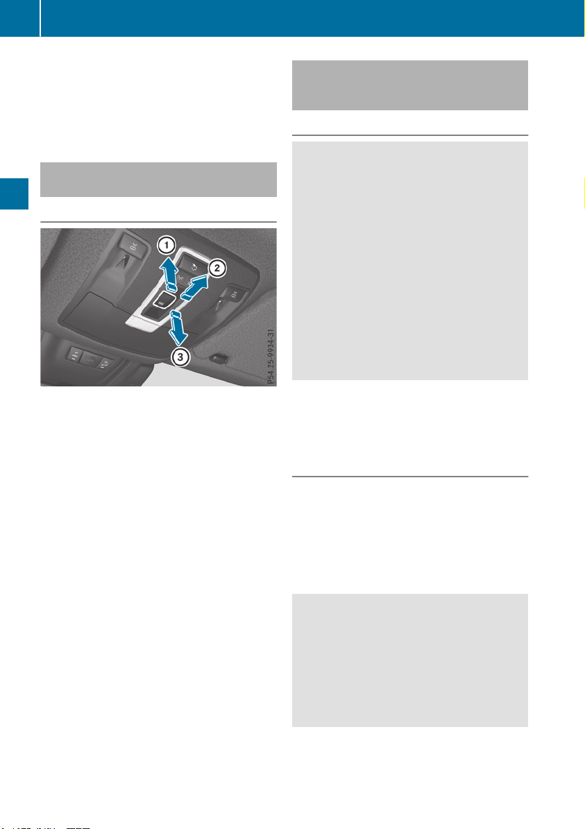
X
Keep the 2 switch pressed for another
second.
X
Make sure that the sliding sunroof can be fully
opened and closed again (Y page 93).
X
If this is not the case, repeat the steps above.
Operating the panorama roof with
power tilt/sliding panel
Opening and closing
:
To raise
;
To open
=
To close/lower
The panorama roof with power tilt/sliding panel
can only be opened when the roller sunblind is
open.
X
Turn the SmartKey to position 1 or 2 in the
ignition lock.
X
Press or pull the 2 switch in the corre-
sponding direction.
If you press/pull the 2 switch beyond the
pressure point, automatic operation is started in
the corresponding direction. You can stop auto-
matic operation by pressing/pulling the switch
again.
The automatic raising feature is available only
when the panorama roof with power tilt/sliding
panel is closed.
Operating the roller sunblinds for the
panorama roof with power tilt/sliding
panel
Important safety notes
G
WARNING
Parts of the body could become trapped
between the roller sunblind and frame or slid-
ing sunroof during automatic opening or clos-
ing. There is a risk of injury.
When opening or closing, make sure that no
body parts are in the sweep of the roller sun-
blind.
If somebody becomes trapped:
R
release the switch immediately, or
R
during automatic operation, push the
switch briefly in any direction
The opening or closing procedure will be stop-
ped.
The roller sunblinds shield the vehicle interior
from sunlight. The roller sunblinds can only be
opened and closed together when the pano-
rama roof with power tilt/sliding panel is closed.
Roller sunblind reversing feature
The roller sunblinds are equipped with an auto-
matic reversing feature. If a solid object blocks
or restricts a roller sunblind during the closing
process, the roller sunblind opens again auto-
matically. However, the automatic reversing
feature is only an aid and is not a substitute of
your attentiveness when closing the roller sun-
blind.
G
WARNING
The reversing feature does not react in par-
ticular to soft, light and thin objects, e.g. small
fingers. This means that the reversing feature
cannot prevent someone being trapped in
these situations. There is a risk of injury.
When closing the roller sunblind, make sure
that no body parts are in the sweep area.
94
Sliding sunroof
Opening and closing
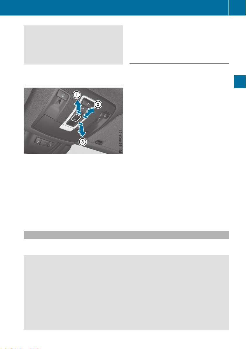
If somebody becomes trapped:
R
release the switch immediately, or
R
press the switch in any direction during the
automatic closing process
The closing process is stopped.
Opening and closing the roller sun-
blinds
:
Opens
;
Opens
=
Closes
X
Turn the SmartKey to position 1 or 2 in the
ignition lock.
X
Press or pull the 2 switch in the corre-
sponding direction.
If you press the 2 switch beyond the pres-
sure point, an automatic opening/closing proc-
ess is started in the corresponding direction.
You can stop automatic operation by pressing/
pulling the switch again.
Resetting the panorama roof with
power tilt/sliding panel and the roller
sunblinds
!
If the panorama roof with power tilt/sliding
panel and the roller sunblinds cannot be fully
opened or closed after resetting, contact a
qualified specialist workshop.
Reset the panorama roof with power tilt/sliding
panel and the roller sunblinds if the panorama
roof with power tilt/sliding panel or the roller
sunblinds do not move smoothly.
X
Turn the SmartKey to position 1 or 2 in the
ignition lock.
X
Pull the 2 switch repeatedly to the point of
resistance in the direction of arrow = until
the panorama roof with power tilt/sliding
panel is fully closed.
X
Keep the 2 switch pulled for an additional
second.
X
Pull the 2 switch repeatedly to the point of
resistance in the direction of arrow = until
the roller sunblinds are fully closed.
X
Keep the 2 switch pulled for an additional
second.
X
Make sure that the panorama roof with power
tilt/sliding panel and the roller sunblinds can
be fully opened again.
X
If this is not the case, repeat the steps above.
Problems with the sliding sunroof
Your vehicle may be equipped with a sliding sunroof or a panorama roof with power tilt/sliding
panel. In the following section, the term "sliding sunroof" refers to both sliding sunroof variants.
G
WARNING
If you close the sliding sunroof again immediately after it has been blocked or reset, the sliding
sunroof closes with increased or maximum force. The reversing feature is then not active. Parts
of the body could be trapped in the closing area in the process. This poses an increased risk of
injury or even fatal injury.
Make sure that no parts of the body are in the closing area.
If somebody becomes trapped:
R
release the switch immediately, or
R
press the switch in any direction during the automatic closing process
The closing process is stopped.
Sliding sunroof
95
Opening and closing
Z

!
If the sliding sunroof still cannot be opened or closed as a result of a malfunction, contact a
qualified specialist workshop.
Problem
Possible causes/consequences and MM Solutions
The sliding sunroof can-
not be closed and you
cannot see the cause.
If the sliding sunroof is obstructed during closing and reopens again
slightly:
X
Immediately after the sliding sunroof blocks, pull the 2 switch in
the overhead control panel down to the point of resistance and hold
it until the sliding sunroof is closed.
The sliding sunroof is closed with increased force.
If the sliding sunroof is obstructed again during closing and then
reopens slightly:
X
Immediately after the sliding sunroof blocks, pull the 2 switch in
the overhead control panel down to the point of resistance and hold
it until the sliding sunroof is closed.
The sliding sunroof is closed without the automatic reversing fea-
ture.
96
Sliding sunroof
Opening and closing
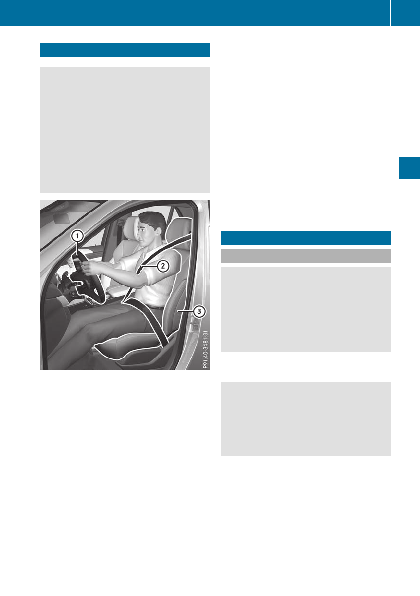
Correct driver's seat position
G
WARNING
You could lose control of your vehicle if you do
the following while driving:
R
adjust the driver's seat, head restraint,
steering wheel or mirrors
R
fasten the seat belt
There is a risk of an accident.
Adjust the driver's seat, head restraint, steer-
ing wheel and mirror and fasten your seat belt
before starting the engine.
Observe the following when adjusting steering
wheel :, seat belt ; and driver's seat =:
R
you are as far away from the driver's air bag as
possible
R
you are sitting in a normal upright position
R
your thighs are slightly supported by the seat
cushion
R
your legs are not entirely stretched and you
can depress the pedals properly
R
the back of your head is supported at eye level
by the center of the head restraint
R
you can hold the steering wheel with your
arms slightly bent
R
you can move your legs freely
R
you can see all the displays in the instrument
cluster clearly
R
you should have a good overview of traffic
conditions
R
the seat belt is pulled snugly against the body
and is routed across the center of your shoul-
der and across your hips in the pelvic area
Further related subjects:
R
Electrical seat adjustment (Y page 98)
R
Adjusting the steering wheel mechanically
(Y page 103) or electrically (Y page 104)
R
Fastening the seat belt correctly (Y page 48).
R
Adjusting the rear-view mirror and exterior
mirrors (Y page 105).
R
Vehicles with memory function: storing the
seat, steering wheel, exterior mirror and
Head-up display settings with the memory
function (Y page 108)
Seats
Important safety notes
G
WARNING
Children could become trapped if they adjust
the seats, particularly when unattended.
There is a risk of injury.
When leaving the vehicle, always take the
SmartKey with you and lock the vehicle. Never
leave children unsupervised in the vehicle.
The seats can still be adjusted when there is no
SmartKey in the ignition lock.
G
WARNING
When you adjust a seat, you or other vehicle
occupants could become trapped, e.g. on the
seat guide rail. There is a risk of injury.
Make sure when adjusting a seat that no one
has any body parts in the sweep of the seat.
Observe the safety notes on "Air bags"
(Y page 49) and "Children in the Vehicle"
(Y page 59).
Seats
97
Seats, steering wheel and mirrors
Z

G
WARNING
You could lose control of your vehicle if you do
the following while driving:
R
adjust the driver's seat, head restraint,
steering wheel or mirrors
R
fasten the seat belt
There is a risk of an accident.
Adjust the driver's seat, head restraint, steer-
ing wheel and mirror and fasten your seat belt
before starting the engine.
G
WARNING
If you adjust the seat height carelessly, you or
other vehicle occupants could be trapped and
thereby injured. Children in particular could
accidentally press the electrical seat adjust-
ment buttons and become trapped. There is a
risk of injury.
While moving the seats, make sure that your
hands or other body parts do not get under the
lever assembly of the seat adjustment sys-
tem.
G
WARNING
If the head restraints are not installed or not
adjusted correctly, they cannot provide pro-
tection as intended. There is an increased risk
of injury in the head and neck area, e.g. in the
event of an accident or when braking.
Always drive with the head restraints instal-
led. Before driving off, make sure for every
vehicle occupant that the center of the head
restraint supports the back of the head at
about eye level.
G
WARNING
The seat belt does not offer the intended level
of protection if you have not moved the back-
rest to an almost vertical position. When brak-
ing or in the event of an accident, you could
slide underneath the seat belt and sustain
abdomen or neck injuries, for example. This
poses an increased risk of injury or even fatal
injury.
Adjust the seat properly before beginning
your journey. Always ensure that the backrest
is in an almost vertical position and that the
shoulder section of your seat belt is routed
across the center of your shoulder.
!
To prevent damage to the seats and the seat
heating, observe the following notes:
R
Do not spill liquids onto the seats. Dry the
seats as soon as possible if liquid does get
spilled on the seats.
R
If the seat covers are damp or wet, do not
switch on the seat heating. Also, do not use
the seat heating to dry the seats.
R
Clean the seat covers as recommended;
see keyword "Care".
R
Do not transport heavy loads on the seats.
Do not place pointed objects on the seat
cushions such as knives, nails or tools.
Where possible, use the seats only for car-
rying passengers.
R
When operating the seat heating, do not
cover the seats with insulating materials,
e.g. blankets, coats, bags, protective cov-
ers, child seats or booster seats.
!
Make sure that there are no objects in the
footwell under or behind the seats when mov-
ing the seats back. There is a risk that the
seats and/or the objects could be damaged.
i Further related subjects:
R
Cargo compartment enlargement (folding
down the rear bench seat) (Y page 298)
Adjusting the seats electrically
:
Head restraint height
;
Seat cushion angle
=
Seat height
98
Seats
Seats, steering wheel and mirrors
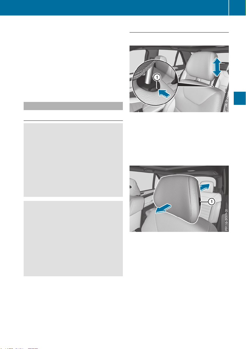
?
Seat fore-and-aft adjustment
A
Backrest angle
i
Vehicles with memory function: if PRE-
SAFE
®
has been triggered, the front-
passenger seat will be moved to a better posi-
tion if it was previously in an unfavorable posi-
tion.
i
Vehicles with memory function: when the
seat is moved forwards or backwards, the
headrest is moved up or down automatically.
Adjusting the head restraints
Important safety notes
G
WARNING
You could lose control of your vehicle if you do
the following while driving:
R
adjust the driver's seat, head restraint,
steering wheel or mirrors
R
fasten the seat belt
There is a risk of an accident.
Adjust the driver's seat, head restraint, steer-
ing wheel and mirror and fasten your seat belt
before starting the engine.
G
WARNING
If the head restraints are not installed or not
adjusted correctly, they cannot provide pro-
tection as intended. There is an increased risk
of injury in the head and neck area, e.g. in the
event of an accident or when braking.
Always drive with the head restraints instal-
led. Before driving off, make sure for every
vehicle occupant that the center of the head
restraint supports the back of the head at
about eye level.
Do not swap the head restraints of the front and
rear seats. Otherwise, you cannot adjust the
height and angle of the head restraints to the
correct position.
Using the fore-and-aft adjustment, adjust the
head restraint so that it is as close as possible to
your head.
Observe the important safety notes regarding
the seats (Y page 97).
Adjusting the head restraints manually
Adjusting the head restraint height
X
To raise: pull the head restraint up to the
desired position.
X
To lower: press release catch : in the direc-
tion of the arrow and push the head restraint
down to the desired position.
Adjusting the fore/aft position of the
head restraint
With this function you can adjust the distance
between the head restraint and the back of the
seat occupant's head.
X
To move forwards: pull the head restraint
forwards in the direction of the arrow until it
engages.
There are several notches.
X
To move backwards: press and hold release
button : and push the head restraint back-
wards.
X
When the head restraint is in the desired posi-
tion, release the button and make sure that
the head restraint is engaged in position.
i
Adjust the head restraint so that the back of
your head is as close to the head restraint as
possible.
Seats
99
Seats, steering wheel and mirrors
Z
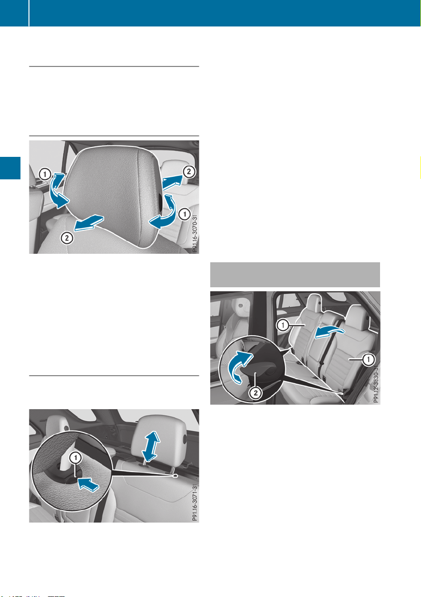
Adjusting the head restraints electri-
cally
X
To adjust the head restraint height: slide
the switch for the head restraint adjustment
(Y page 98) up or down in the direction of the
arrow.
Adjusting the luxury head restraints
X
To adjust the side bolsters of the head
restraint: push or pull right and/or left-hand
side bolster : into the desired position.
X
To adjust the fore/aft position of the head
restraint: push or pull the head restraint in
the direction of arrow ;.
i
Adjust the head restraint so that the back of
your head is as close to the head restraint as
possible.
Rear seat head restraints
Adjusting the rear seat head restraint
height
X
Once the head restraint is fully lowered, press
release catch :.
X
To raise: pull the head restraint up to the
desired position.
X
To lower: press release catch : and push
the head restraint down until it is in the
desired position.
Removing and installing the rear seat
head restraints
X
To remove: pull the head restraint up to the
stop.
X
Press release catch : and pull the head
restraint out of the guides.
X
To re-install: insert the head restraint so that
the notches on the bar are on the left when
viewed in the direction of travel.
X
Push the head restraint down until you hear it
engage in position.
Adjusting the angle of the rear seat
backrests
You can adjust the angle of the backrests in the
second row of seats. There are several possible
detent positions.
X
Pull the left or right release lever ; upwards
in the direction of the arrow until relevant
backrest : is fully released.
X
Pull backrest : forwards in the direction of
the arrow and allow it to engage.
X
To ensure that the backrest has engaged, lean
firmly against backrest :.
100
Seats
Seats, steering wheel and mirrors
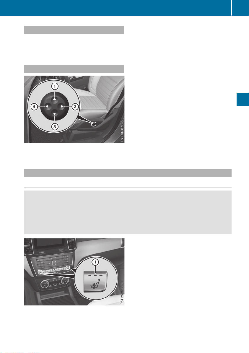
Adjusting the multicontour seat
The multicontour seat can be adjusted via the
multimedia system (see the Digital Operator's
Manual).
Adjusting the 4-way lumbar support
:
Raises the backrest contour
;
Softens the backrest contour
=
Lowers the backrest contour
?
Hardens the backrest contour
You can adjust the contour of the front seat
backrests individually to provide optimum sup-
port for your back.
Seat heating and seat ventilation
Switching the seat heating on/off
G
WARNING
Repeatedly switching on the seat heating can cause the seat cushion and backrest pads to
become very hot. The health of persons with limited temperature sensitivity or a limited ability to
react to high temperatures may be affected or they may even suffer burn-like injuries. There is a
risk of injury.
Therefore, do not switch the seat heating on repeatedly.
:
Driver's and front-passenger seat
Seats
101
Seats, steering wheel and mirrors
Z
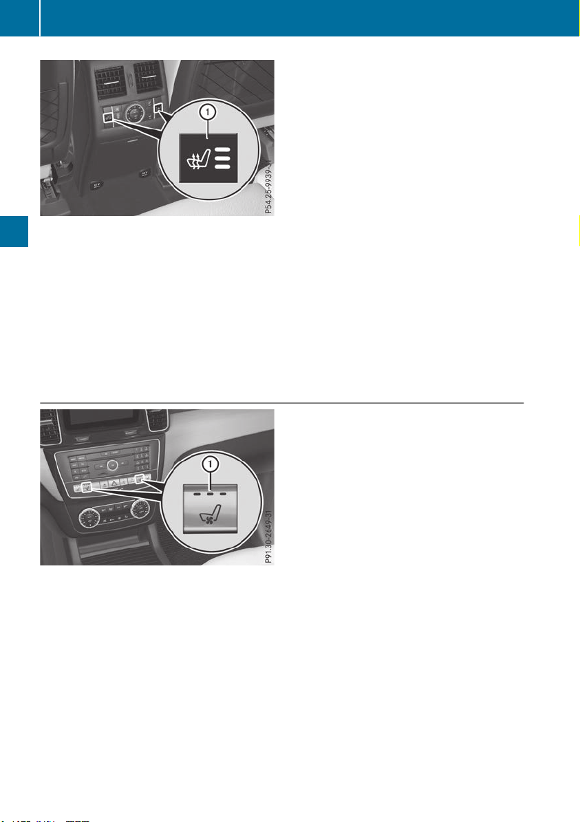
:
Rear seats
The three red indicator lamps in the button indicate the heating level you have selected.
The system automatically switches down from level 3 to level 2 after approximately eight minutes.
The system automatically switches down from level 2 to level 1 after approximately ten minutes.
The system automatically switches off approximately 35 minutes after it is set to level 1.
X
Turn the SmartKey to position 1 or 2 in the ignition lock (Y page 135).
X
To switch on: press button : repeatedly until the desired heating level is set.
X
To switch off: press button : repeatedly until all the indicator lamps go out.
i
If the battery voltage is too low, the seat heating may switch off.
Activating/deactivating seat ventilation
The three blue indicator lamps in the buttons indicate the blower setting you have selected.
X
Turn the SmartKey to position 1 or 2 in the ignition lock (Y page 135).
X
To switch on: press button : repeatedly until the desired blower setting is set.
X
To switch off: press button : repeatedly until all the indicator lamps go out.
i
If the battery voltage is too low, the seat ventilation may switch off.
i
You can open the side windows and the sliding sunroof using the "Convenience opening" feature
(Y page 89). The seat ventilation of the driver's seat automatically switches to the highest level.
102
Seats
Seats, steering wheel and mirrors
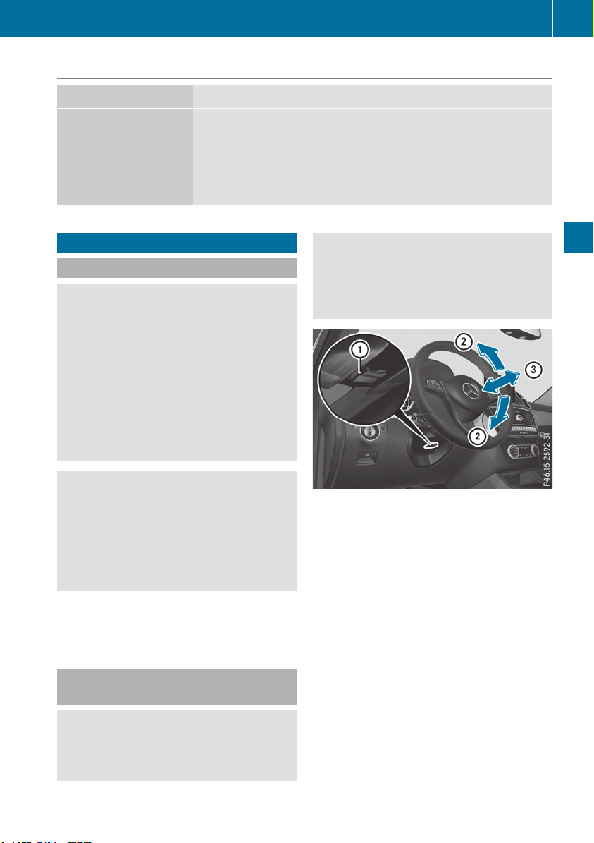
Problems with the seat heating or seat ventilation
Problem
Possible causes/consequences and MM Solutions
The seat heating or seat
ventilation has switched
off prematurely or can-
not be switched on.
The on-board voltage is too low because too many electrical consum-
ers are switched on.
X
Switch off electrical consumers that you do not need, such as the
rear window defroster or interior lighting.
Once the battery is sufficiently charged, the seat heating or seat
ventilation will switch back on automatically.
Steering wheel
Important safety notes
G
WARNING
You could lose control of your vehicle if you do
the following while driving:
R
adjust the driver's seat, head restraint,
steering wheel or mirrors
R
fasten the seat belt
There is a risk of an accident.
Adjust the driver's seat, head restraint, steer-
ing wheel and mirror and fasten your seat belt
before starting the engine.
G
WARNING
Children could injure themselves if they
adjust the steering wheel. There is a risk of
injury.
When leaving the vehicle, always take the
SmartKey with you and lock the vehicle. Never
leave children unsupervised in the vehicle.
The electrically adjustable steering wheel can
still be adjusted when there is no SmartKey in
the ignition lock.
Adjusting the steering wheel man-
ually
G
WARNING
If the steering wheel is unlocked while the
vehicle is in motion, it could change position
unexpectedly. This could cause you to lose
control of the vehicle. There is a risk of an
accident.
Before starting off, make sure the steering
wheel is locked. Never unlock the steering
wheel while the vehicle is in motion.
:
Release lever
;
Adjusts the steering wheel height
=
Adjusts the steering wheel position (fore-
and-aft adjustment)
X
Push release lever : down completely.
The steering column is unlocked.
X
Adjust the steering wheel to the desired posi-
tion.
X
Push release lever : up completely.
The steering column is locked.
X
Check if the steering column is locked. When
doing so, try to push the steering wheel up or
down or try to move it in the fore-and-aft
direction.
Steering wheel
103
Seats, steering wheel and mirrors
Z
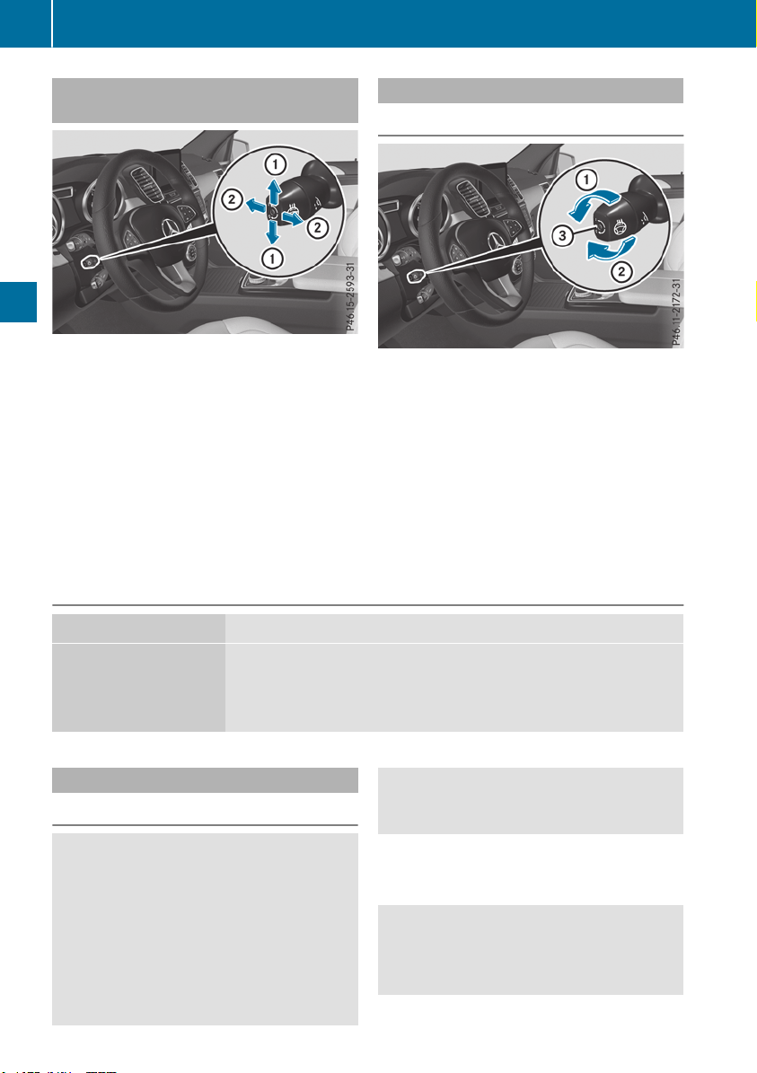
Adjusting the steering wheel electri-
cally
:
Adjusts the steering wheel height
;
Adjusts the steering wheel position (fore-
and-aft adjustment)
The steering wheel can also be adjusted when
the SmartKey is removed from the ignition lock.
i Further related subjects:
R
EASY-ENTRY/EXIT feature (Y page 104)
R
Storing settings (Y page 108)
Steering wheel heating
Switching on/off
X
Turn the SmartKey to position 2 in the igni-
tion lock (Y page 135).
X
To switch on/off: turn the lever in the direc-
tion of arrow : or ;.
Indicator lamp = lights up or goes out.
Vehicles with KEYLESS-GO: when you switch off
the ignition and open the driver's door, the
steering wheel heating is deactivated.
Vehicles without KEYLESS-GO: when you
remove the SmartKey from the ignition lock, the
steering wheel heating is deactivated.
Problems with the steering wheel heating
Problem
Possible causes/consequences and MM Solutions
The steering wheel heat-
ing has switched off pre-
maturely or cannot be
switched on.
The on-board voltage is too low because too many electrical consum-
ers are switched on.
X
Switch off electrical consumers that you do not need, such as the
rear window defroster or interior lighting.
EASY-ENTRY/EXIT feature
Important safety notes
G
WARNING
When the EASY-ENTRY/EXIT feature adjusts
the steering wheel, you and other vehicle
occupants – particularly children – could
become trapped. There is a risk of injury.
While the EASY-ENTRY/EXIT feature is mak-
ing adjustments, make sure that no one has
any body parts in the sweep of the steering
wheel.
Move the steering wheel adjustment lever if
there is a risk of entrapment by the steering
wheel. The adjustment process is stopped.
Press one of the memory function position but-
tons. This function is only available on vehicles
with memory function.
G
WARNING
If children activate the EASY-ENTRY/EXIT fea-
ture, they can become trapped, particularly
when unattended. There is a risk of injury.
104
Steering wheel
Seats, steering wheel and mirrors
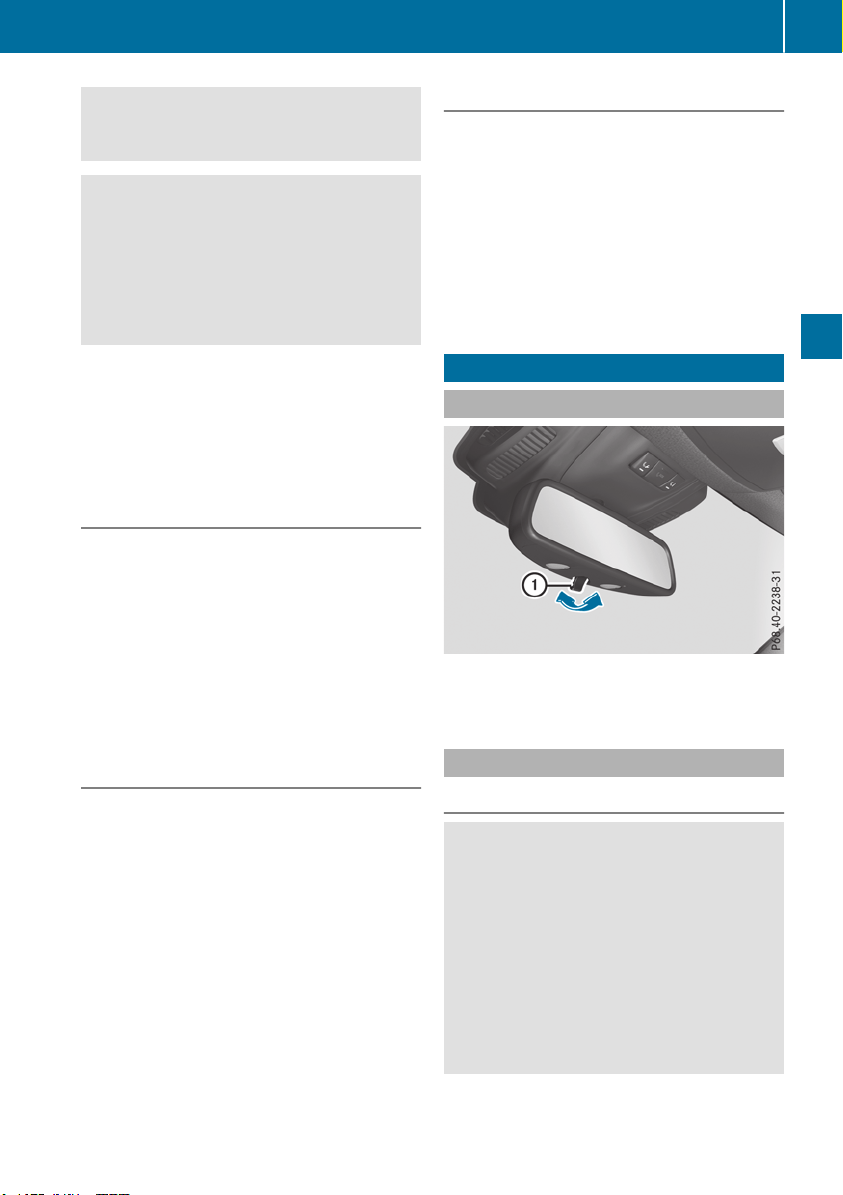
When leaving the vehicle, always take the
SmartKey with you and lock the vehicle. Never
leave children unsupervised in the vehicle.
G
WARNING
If you drive off while the EASY-ENTRY/EXIT
feature is making adjustments, you could lose
control of the vehicle. There is a risk of an
accident.
Always wait until the adjustment process is
complete before driving off.
The EASY-ENTRY/EXIT feature makes getting in
and out of your vehicle easier.
You can activate and deactivate the EASY-
ENTRY/EXIT feature in the on-board computer
(Y page 240).
Position of the steering wheel when the
EASY-ENTRY/EXIT feature is active
The steering wheel swings up when you:
R
remove the SmartKey from the ignition lock.
R
open the driver's door and KEYLESS-GO is in
position 1.
R
open the driver's door and the SmartKey is in
position u or 1 in the ignition lock.
i
The steering wheel only moves up if it has
not already reached the upper stop.
Position of the steering wheel for driv-
ing
The steering wheel is moved to the last selected
position when:
R
the driver's door is closed
R
you insert the SmartKey into the ignition lock
or
R
you press the Start/Stop button once on vehi-
cles with KEYLESS-GO
When you close the driver's door with the igni-
tion switched on, the steering wheel is also
automatically moved to the previously set posi-
tion.
The last position of the steering column is stored
when you:
R
switch the ignition off
R
save the setting with the memory function
(Y page 108).
Crash-responsive EASY-EXIT feature
If the crash-responsive EASY-EXIT feature is trig-
gered in an accident, the steering column will
move upwards when the driver's door is opened.
This occurs irrespective of the position of the
SmartKey in the ignition lock. This makes it eas-
ier to exit the vehicle and rescue the occupants.
The crash-responsive EASY-EXIT feature is only
operational if the EASY-EXIT/ENTRY feature is
activated in the on-board computer
(Y page 240).
Mirrors
Rear-view mirror
X
Anti-glare mode: flick anti-glare lever : for-
wards or back.
Exterior mirrors
Adjusting the exterior mirrors
G
WARNING
You could lose control of your vehicle if you do
the following while driving:
R
adjust the driver's seat, head restraint,
steering wheel or mirrors
R
fasten the seat belt
There is a risk of an accident.
Adjust the driver's seat, head restraint, steer-
ing wheel and mirror and fasten your seat belt
before starting the engine.
Mirrors
105
Seats, steering wheel and mirrors
Z
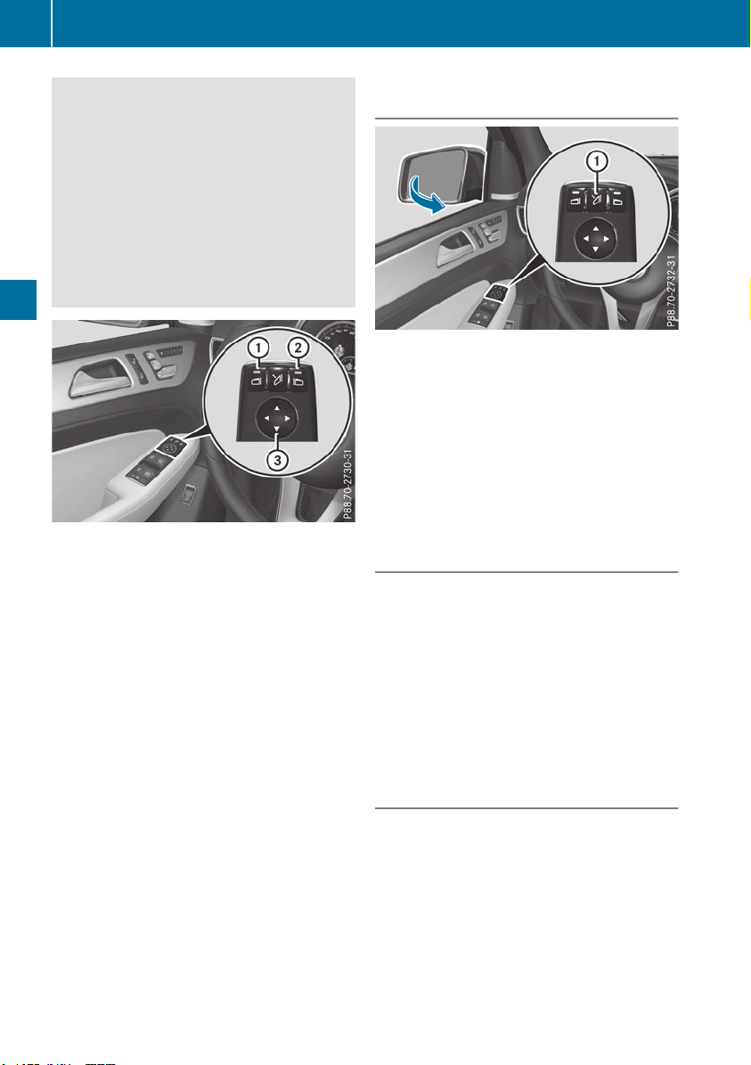
G
WARNING
The exterior mirror on the front-passenger
side reduces the size of the image. Visible
objects are actually closer than they appear.
This means that you could misjudge the dis-
tance from road users traveling behind, e.g.
when changing lane. There is a risk of an acci-
dent.
For this reason, always make sure of the
actual distance from the road users traveling
behind by glancing over your shoulder.
X
Turn the SmartKey to position 1 or 2 in the
ignition lock (Y page 135).
X
Exterior mirror on the driver's side: press but-
ton :.
Exterior mirror on the front-passenger side:
press button ;.
The indicator lamp in the corresponding but-
ton lights up in red.
The indicator lamp goes out again after some
time. You can adjust the selected exterior
mirror using button = as long as the indicator
lamp is lit.
X
Press button = up, down, or to the right or
left until you have adjusted the exterior mirror
to the correct position. You should have a
good overview of traffic conditions.
The convex exterior mirrors provide a larger field
of vision.
The exterior mirrors are heated automatically if
the rear window defroster is switched on and the
outside temperature is low.
Folding the exterior mirrors in or out
electrically
X
Turn the SmartKey to position 1 or 2 in the
ignition lock (Y page 135).
X
Briefly press :.
Both exterior mirrors fold in or out.
i
Make sure that the exterior mirrors are
always folded out fully while driving. They
could otherwise vibrate.
i
If you are driving faster than 30 mph
(47 km/h), you can no longer fold in the exte-
rior mirrors.
Resetting the exterior mirrors
If the battery has been disconnected or com-
pletely discharged, the exterior mirrors must be
reset. Otherwise, the exterior mirrors will not
fold in when you select the "Fold in mirrors when
locking" function in the on-board computer
(Y page 241).
X
Turn the SmartKey to position 1 in the igni-
tion lock (Y page 135).
X
Briefly press :.
Folding the exterior mirrors in or out
automatically
If the "Fold in mirrors when locking" function is
activated in the on-board computer
(Y page 241):
R
the exterior mirrors fold in automatically as
soon as you lock the vehicle from the outside.
R
the exterior mirrors fold out again automati-
cally as soon as you unlock the vehicle and
then open the driver's or front-passenger
door.
106
Mirrors
Seats, steering wheel and mirrors
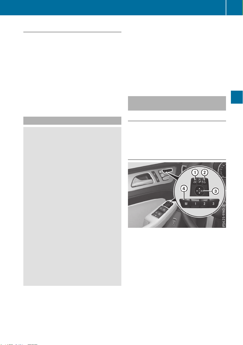
Exterior mirror pushed out of position
If an exterior mirror has been pushed out of
position, proceed as follows:
X
Vehicles without electrically folding exte-
rior mirrors: move the exterior mirror into
the correct position manually.
X
Vehicles with electrically folding exterior
mirrors: press and hold mirror-folding but-
ton : until you hear a click and the mirror
engages in position audibly.
The mirror housing is engaged again and you
can adjust the exterior mirrors as usual
(Y page 105).
Automatic anti-glare mirrors
G
WARNING
Electrolyte may escape if the glass in an auto-
matic anti-glare mirror breaks. The electrolyte
is harmful and causes irritation. It must not
come into contact with your skin, eyes, res-
piratory organs or clothing or be swallowed.
There is a risk of injury.
If you come into contact with the electrolyte,
observe the following:
R
Rinse off the electrolyte from your skin
immediately with water.
R
Immediately rinse the electrolyte out of
your eyes thoroughly with clean water.
R
If the electrolyte is swallowed, immediately
rinse your mouth out thoroughly. Do not
induce vomiting.
R
If electrolyte comes into contact with your
skin or hair or is swallowed, seek medical
attention immediately.
R
Immediately change out of clothing which
has come into contact with electrolyte.
R
If an allergic reaction occurs, seek medical
attention immediately.
The rear-view mirror and the exterior mirror on
the driver's side automatically go into anti-glare
mode if the following conditions are met simul-
taneously:
R
the ignition is switched on and
R
incident light from headlamps strikes the sen-
sor in the rear-view mirror
The mirrors do not go into anti-glare mode if
reverse gear is engaged or if the interior lighting
is switched on.
Parking position for the exterior mir-
ror on the front-passenger side
Setting and storing the parking position
You can position the front-passenger side exte-
rior mirror in such a way that you can see the
rear wheel on that side as soon as you engage
reverse gear. You can store this position.
Using reverse gear
:
Button for the driver's side exterior mirror
;
Button for the front-passenger side exterior
mirror
=
Switch
?
Memory button M
X
Bring the vehicle to a standstill.
X
Turn the SmartKey to position 2 in the igni-
tion lock (Y page 135).
X
Press button ;.
Mirrors
107
Seats, steering wheel and mirrors
Z

X
Engage reverse gear.
The exterior mirror on the front-passenger
side moves to the default setting parking posi-
tion.
X
Use button = to adjust the exterior mirror to
a position that allows you to see the rear
wheel and the curb.
The parking position is stored.
i
If you shift the transmission to another posi-
tion, the exterior mirror on the front-
passenger side returns to the driving position.
Using the memory button
You can store the parking position of the exte-
rior mirror on the front-passenger side using
memory button M ?. The reverse gear must not
be engaged during the process.
X
Turn the SmartKey to position 2 in the igni-
tion lock (Y page 135).
X
Press button ;.
X
Use button = to adjust the exterior mirror to
a position that allows you to see the rear
wheel and the curb.
X
Press memory button M ? and one of the
arrows on button = within three seconds.
The parking position is stored if the exterior
mirror does not move.
X
If the mirror moves out of position, repeat the
steps.
Calling up a stored parking position set-
ting
X
Turn the SmartKey to position 2 in the igni-
tion lock (Y page 135).
X
Adjust the exterior mirror on the front-
passenger side using button ;.
X
Engage reverse gear.
The exterior mirror on the front-passenger
side moves to the stored parking position.
The exterior mirror on the front-passenger side
moves back to its original position:
R
as soon as you exceed a speed of 9 mph
(15 km/h)
R
when you use button : to select the exterior
mirror on the driver's side
Memory function
Storing settings
G
WARNING
If you use the memory function on the driver's
side while driving, you could lose control of
the vehicle as a result of the adjustments
being made. There is a risk of an accident.
Only use the memory function on the driver's
side when the vehicle is stationary.
G
WARNING
When the memory function adjusts the seat or
steering wheel, you and other vehicle occu-
pants – particularly children – could become
trapped. There is a risk of injury.
While the memory function is making adjust-
ments, make sure that no one has any body
parts in the sweep of the seat or steering
wheel. If somebody becomes trapped, imme-
diately release the memory function position
button. The adjustment process is stopped.
G
WARNING
Children could become trapped if they acti-
vate the memory function, particularly when
unattended. There is a risk of injury.
When leaving the vehicle, always take the
SmartKey with you and lock the vehicle. Never
leave children unsupervised in the vehicle.
The memory function can be used at any time,
e.g. even when the SmartKey isn't in the ignition
lock.
With the memory function, you can store up to
three different settings, e.g. for three different
people.
The following settings are stored as a single
memory preset:
R
position of the seat, backrest and head
restraint
R
driver's side: steering wheel position
R
driver's side: position of the exterior mirrors
on the driver's and front-passenger sides
108
Memory function
Seats, steering wheel and mirrors
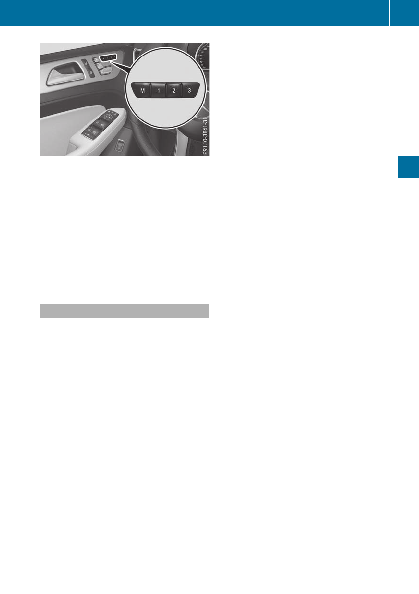
X
Adjust the seat (Y page 98).
X
On the driver's side, adjust the steering wheel
(Y page 104) and the exterior mirrors
(Y page 105).
X
Press memory button M and then press mem-
ory position button 1, 2 or 3 within three sec-
onds.
The settings are stored in the selected preset
position. A tone sounds when the settings
have been completed.
The memory function can still be used if the
SmartKey has been removed.
Calling up a stored setting
X
Press and hold the relevant storage position
button 1, 2 or 3 until the seat, steering wheel
and exterior mirrors are in the stored position.
The setting procedure is interrupted as soon as
you release the storage position buttons.
Memory function
109
Seats, steering wheel and mirrors
Z
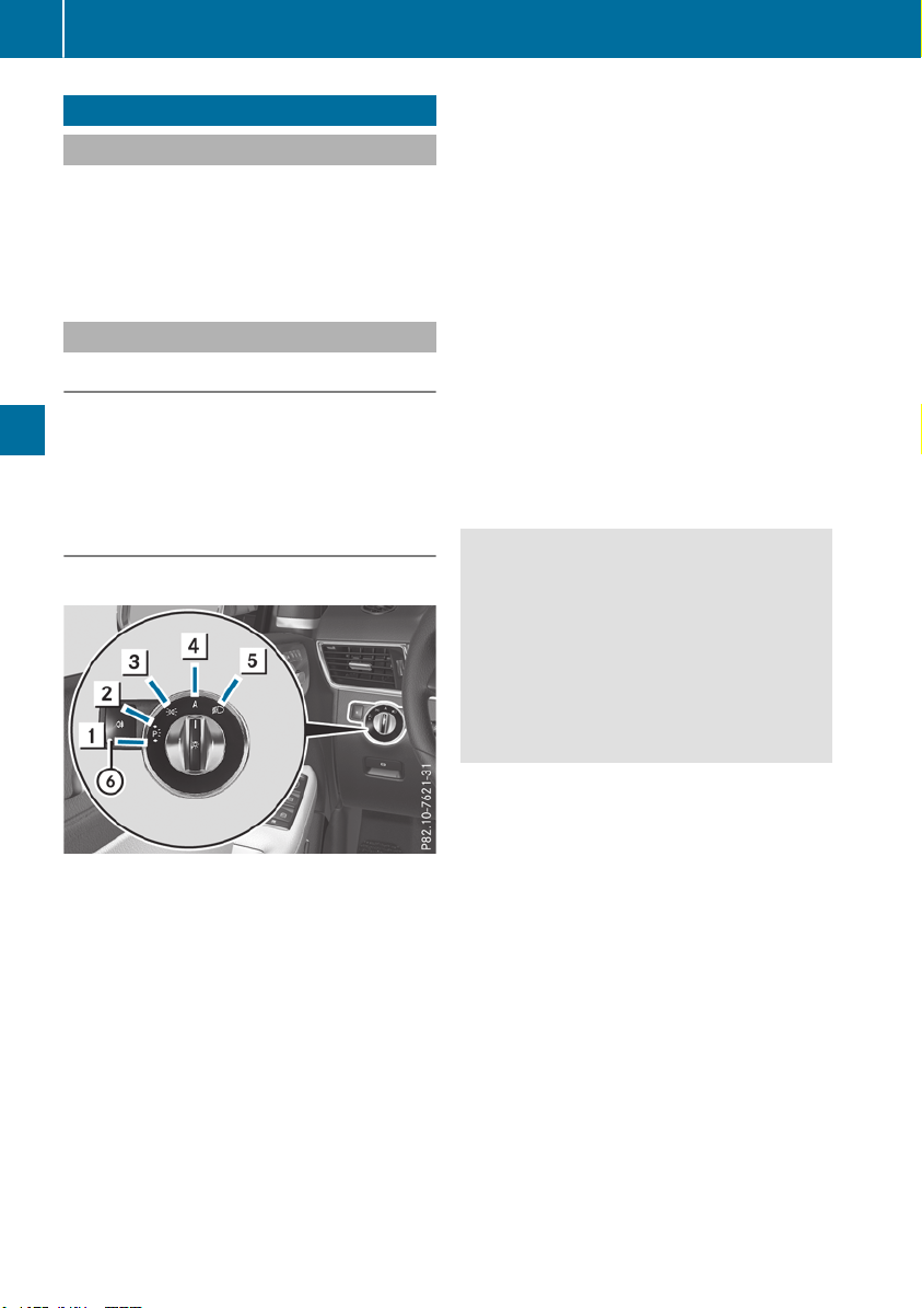
Exterior lighting
General notes
For reasons of safety, Mercedes-Benz recom-
mends that you drive with the lights switched on
even during the daytime. In some countries,
operation of the headlamps varies due to legal
requirements and self-imposed obligations.
Setting the exterior lighting
Setting options
Exterior lighting can be set using:
R
the light switch
R
the combination switch (Y page 111)
R
the on-board computer (Y page 239)
Light switch
Operation
1 W
Left-hand standing lamps
2 X
Right-hand standing lamps
3 T
Parking lamps, license plate and
instrument cluster lighting
4 c
Automatic headlamp mode, controlled
by the light sensor
5 L
Low-beam/high-beam headlamps
B R
Rear fog lamp
If you hear a warning tone when you leave the
vehicle, the lights may still be switched on.
X
Turn the light switch to c.
The exterior lighting (except the parking/stand-
ing lamps) switches off automatically if you:
R
remove the SmartKey from the ignition lock
R
open the driver's door with the SmartKey in
position u in the ignition lock
Automatic headlamp mode
c is the favored light switch position. The
light setting is automatically selected according
to the brightness of the ambient light (excep-
tion: poor visibility due to weather conditions
such as fog, snow or spray):
R
SmartKey in position 1 in the ignition lock:
the parking lamps are switched on/off auto-
matically depending on the brightness of the
ambient light.
R
With the engine running (USA only): if you
have switched on the Daytime RunningDaytime Running
LightsLights function in the on-board computer,
the daytime running lamps or the parking
lamps and low-beam headlamps are switched
on or off automatically depending on the
brightness of the ambient light.
X
To switch on automatic headlamp mode:
turn the light switch to c.
G
WARNING
When the light switch is set to Ã, the low-
beam headlamps may not be switched on
automatically if there is fog, snow or other
causes of poor visibility due to the weather
conditions such as spray. There is a risk of an
accident.
In such situations, turn the light switch to
L.
The automatic headlamp mode is only an aid.
The driver is responsible for the vehicle's light-
ing at all times.
Canada only:
The daytime running lamps improve the visibility
of your vehicle during the day. The daytime run-
ning lamps function is required by law in Can-
ada. It cannot therefore be deactivated.
When the engine is running and the vehicle is
stationary: if you move the selector lever from a
driving position to P, the daytime running
lamps/low-beam headlamps go out after three
minutes.
When the engine is running, the vehicle is sta-
tionary and in bright ambient light: if you turn the
light switch to the T position, the daytime
running lamps and parking lamps switch on.
If the engine is running and you turn the light
switch to L, the manual settings take prec-
edence over the daytime running lamps.
USA only:
110
Exterior lighting
Lights and windshield wipers
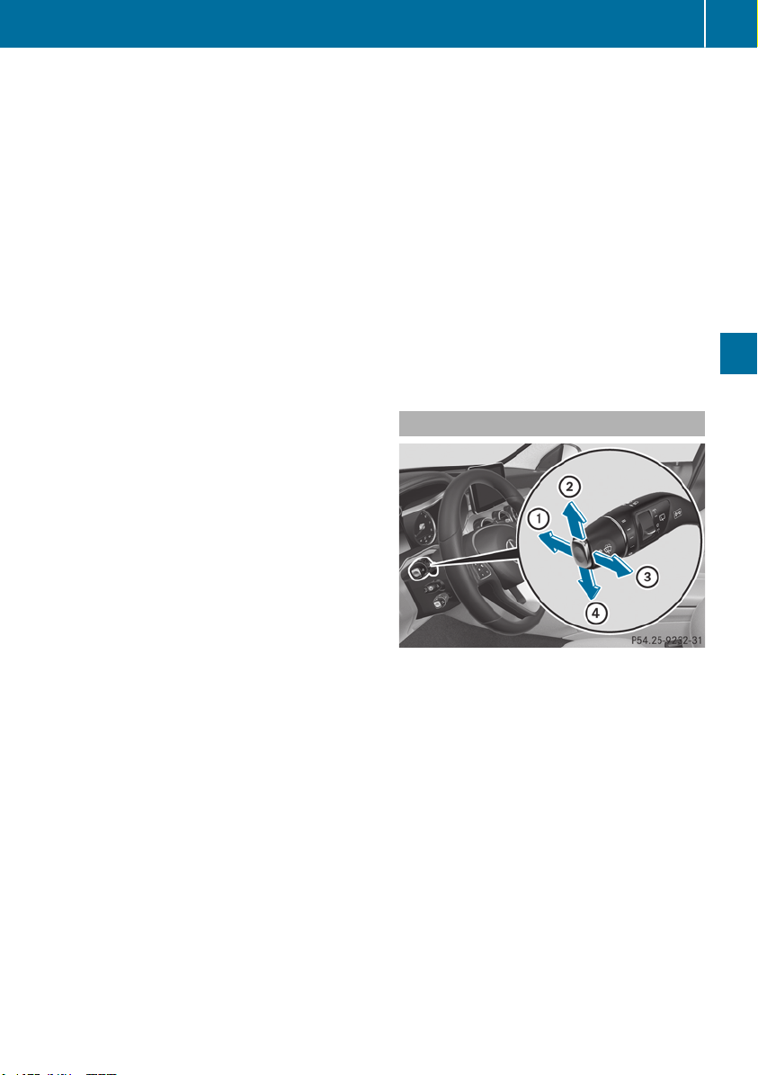
The daytime running lamps improve the visibility
of your vehicle during the day. To do this, the
daytime running lamps function must be
switched on using the on-board computer
(Y page 239).
If the engine is running and you turn the light
switch to T or L, the manual settings
take precedence over the daytime running
lamps.
Low-beam headlamps
Even if the light sensor does not detect that it is
dark, the parking lamps and low-beam head-
lamps switch on when the ignition is switched on
and the light switch is set to the L position.
This is a particularly useful function in the event
of rain and fog.
X
To switch on the low-beam headlamps:
turn the SmartKey to position 2 in the igni-
tion lock or start the engine.
X
Turn the light switch to L.
The green L indicator lamp in the instru-
ment cluster lights up.
Rear fog lamp
The rear fog lamp improves visibility of your
vehicle for the traffic behind in the event of thick
fog. Please take note of the country-specific
regulations for the use of rear fog lamps.
X
To switch on the rear fog lamp: turn the
SmartKey to position 2 in the ignition lock or
start the engine.
X
Turn the light switch to L or c.
X
Press the R button.
The yellow R indicator lamp in the instru-
ment cluster lights up.
X
To switch off the rear fog lamp: press the
R button.
The yellow R indicator lamp in the instru-
ment cluster goes out.
Parking lamps
!
If the battery charge is very low, the parking
lamps or standing lamps are automatically
switched off to enable the next engine start.
Always park your vehicle safely and in a well lit
area, in accordance with the relevant legal
stipulations. Avoid using the T parking
lamps over a period of several hours. If pos-
sible, switch on the right-hand X or left-
hand W standing lamps.
X
To switch on: turn the light switch to T.
The green T indicator lamp in the instru-
ment cluster lights up.
Standing lamps
Switching on the standing lamps ensures the
corresponding side of the vehicle is illuminated.
X
To switch on the standing lamps: the
SmartKey should not be in the ignition lock or
in key position u in the ignition lock.
X
Turn the light switch to W (left-hand side of
the vehicle) or X (right-hand side of the
vehicle).
Vehicles towing a trailer: both the right-hand
and left-hand standing lamps (tail lamps) are
always illuminated on the trailer.
Combination switch
:
High-beam headlamps
;
Turn signal, right
=
High-beam flasher
?
Turn signal, left
X
To indicate briefly: press the combination
switch briefly to the pressure point in the
direction of arrow ; or ?.
The corresponding turn signal flashes three
times.
X
To indicate: press the combination switch
beyond the pressure point in the direction of
arrow ; or ?.
X
To switch on the high-beam headlamps:
turn the light switch to L or Ã.
X
Press the combination switch beyond the
pressure point in the direction of arrow :.
In the à position, the high-beam head-
lamps are only switched on when it is dark and
the engine is running.
Exterior lighting
111
Lights and windshield wipers
Z
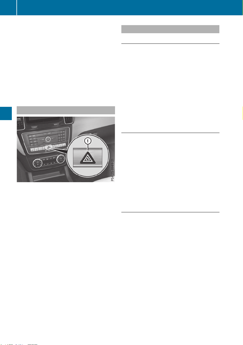
The blue K indicator lamp in the instru-
ment cluster lights up when the high-beam
headlamps are switched on.
X
To switch off the high-beam headlamps:
move the combination switch back to its nor-
mal position.
The blue K indicator lamp in the instru-
ment cluster goes out.
Vehicles with Adaptive Highbeam Assist: if
Adaptive Highbeam Assist is activated, it auto-
matically controls activation and deactivation of
the high-beam headlamps (Y page 113).
Hazard warning lamps
X
To switch on the hazard warning lamps:
press button :.
All turn signals flash. If you now switch on a
turn signal using the combination switch, only
the turn signal lamp on the corresponding
side of the vehicle will flash.
X
To switch off the hazard warning lamps:
press button :.
The hazard warning lamps automatically switch
on if:
R
an air bag is deployed or
R
the vehicle decelerates rapidly from a speed
of above 45 mph (70 km/h) and comes to a
standstill
The hazard warning lamps switch off automati-
cally if the vehicle reaches a speed of above
6 mph (10 km/h) again after a full brake appli-
cation.
i
The hazard warning lamps still operate if the
ignition is switched off.
Intelligent Light System
General notes
The Intelligent Light System is a system that
adjusts the headlamps automatically to suit the
prevailing driving and weather conditions. It
offers advanced functions for improved illumi-
nation of the road surface, e.g. depending on the
vehicle speed or weather conditions. The sys-
tem includes the active light function, cornering
light function, highway mode and extended
range fog lamps. The system is only active when
it is dark.
You can activate or deactivate the "Intelligent
Light System" using the on-board computer
(Y page 239).
Active light function
The active light function is a system that moves
the headlamps according to the steering move-
ments of the front wheels. In this way, relevant
areas remain illuminated while driving. This
allows you to recognize pedestrians, cyclists
and animals sooner.
Active: when the lights are switched on.
Vehicles with Lane Keeping Assist: the active
light function evaluates the course of the lane in
which you are driving and adjusts the light in
advance.
Cornering light function
The cornering light function improves the illu-
mination of the road over a wide angle in the
direction you are turning, enabling better visi-
bility in tight bends, for example. It can only be
activated when the low-beam headlamps are
switched on.
Active:
R
if you are driving at speeds below 25 mph
(40 km/h) and switch on the turn signal or
turn the steering wheel
R
if you are driving at speeds between 25 mph
(40 km/h) and 45 mph (70 km/h) and turn
the steering wheel
The cornering lamp may remain lit for a short
time, but is automatically switched off after no
more than three minutes.
Cornering light function with traffic circle
function:
112
Exterior lighting
Lights and windshield wipers

The cornering light function is activated on both
sides before entering a traffic circle through an
evaluation of the current GPS position of the
vehicle. It remains active until after the vehicle
has left the traffic circle. In this way, pedestrians
crossing the road, for example, are illuminated
by your vehicle in good time.
Highway mode
Highway mode increases the range of the beam.
Active: if you are driving at a speed above
110 km/h and do not make any large steering
movements for at least 1,000 m or if you are
driving at a speed above 130 km/h.
Not active: if you are driving at speeds below
80 km/h following activation.
Extended range fog lamps
The extended range fog lamps reduce the glare
experienced by the driver and improve the illu-
mination of the edge of the road.
Active: if you are driving at speeds below
40 mph (70 km/h) and you switch on the rear
fog lamp.
Not active: if, following activation, you are driv-
ing at speeds above 60 mph (100 km/h) or if you
switch off the rear fog lamp
Off-road lights
The off-road lights facilitate the early recogni-
tion of objects/obstacles when driving off-road
thanks to a symmetrical, wider and brighter dis-
tribution of light from the low-beam headlamps.
Active: when driving at speeds no faster than
30 mph (50 km/h) and the off-road program
selector wheel is in position 1 or 2.
Not active: when driving at speeds above
30 mph (50 km/h).
When the off-road lights are switched on, the
cornering light function is permanently activa-
ted, the active light function is deactivated and
the headlamp range control is set to static
mode.
Adaptive Highbeam Assist
General notes
You can use this function to set the headlamps
to change between low beam and high beam
automatically. The system recognizes vehicles
with their lights on, either approaching from the
opposite direction or traveling in front of your
vehicle, and consequently switches the head-
lamps from high beam to low beam.
The system automatically adapts the low-beam
headlamp range depending on the distance to
the other vehicle. Once the system no longer
detects any other vehicles, it reactivates the
high-beam headlamps.
The system's optical sensor is located behind
the windshield near the overhead control panel.
Important safety notes
G
WARNING
Adaptive Highbeam Assist does not recognize
road users:
R
who have no lights, e.g. pedestrians
R
who have poor lighting, e.g. cyclists
R
whose lighting is blocked, e.g. by a barrier
On very rare occasions, Adaptive Highbeam
Assist may fail to recognize other road users
that have lights, or may recognize them too
late. In this, or in similar situations, the auto-
matic high-beam headlamps will not be deac-
tivated or will be activated regardless. There is
a risk of an accident.
Always carefully observe the traffic conditions
and switch off the high-beam headlamps in
good time.
Adaptive Highbeam Assist cannot take into
account road, weather or traffic conditions.
Adaptive Highbeam Assist is only an aid. You are
responsible for adjusting the vehicle's lighting
to the prevailing light, visibility and traffic con-
ditions.
In particular, the detection of obstacles can be
impaired if:
R
poor visibility, e.g. due to fog, heavy rain or
snow
R
dirt on the sensors or the sensors are
obscured
Exterior lighting
113
Lights and windshield wipers
Z
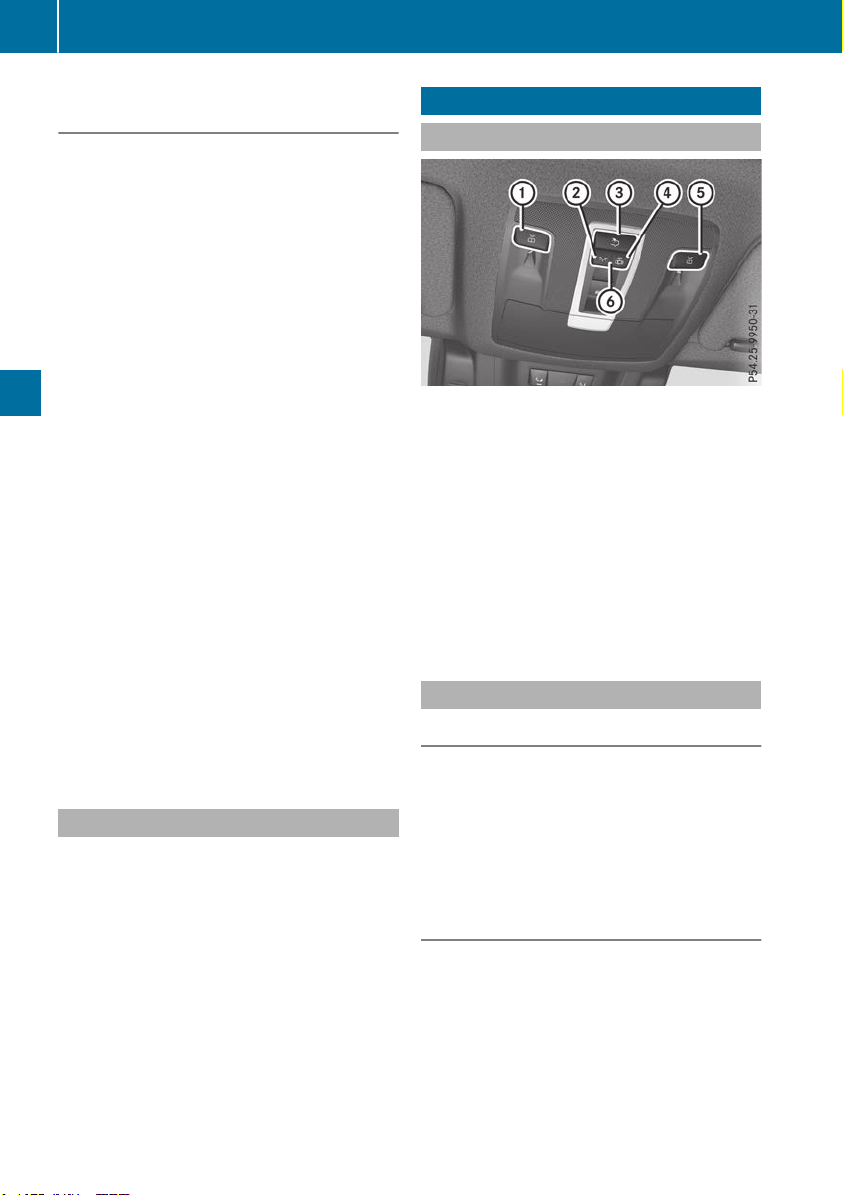
Switching Adaptive Highbeam Assist
on/off
X
To switch on: turn the light switch to Ã.
X
Press the combination switch beyond the
pressure point in the direction of arrow :.
The _ indicator lamp in the multifunction
display lights up when it is dark and the light
sensor activates the low-beam headlamps.
If you are driving at speeds above approx-
imately 16 mph (25 km/h):
The headlamp range is set automatically
depending on the distance between the vehi-
cle and other road users.
If you are driving at speeds above approx-
imately 19 mph (30 km/h) and no other road
users have been detected:
The high-beam headlamps are switched on
automatically. The K indicator lamp in the
instrument cluster also lights up.
If you are driving at speeds below approx-
imately 16 mph (25 km/h) or other road users
have been detected or the roads are ade-
quately lit:
The high-beam headlamps are switched off
automatically. The K indicator lamp in the
instrument cluster goes out. The _ indi-
cator lamp in the multifunction display
remains lit.
X
To switch off: move the combination switch
back to its normal position or move the light
switch to another position.
The _ indicator lamp in the multifunction
display goes out.
Headlamps fogged up on the inside
Certain climatic and physical conditions may
cause moisture to form in the headlamp. This
moisture does not affect the functionality of the
headlamp.
Interior lighting
Overview of interior lighting
Overhead control panel
:
p Switches the left-hand front reading
lamp on/off
;
c Switches the front interior lighting on
=
v Switches the rear interior lighting on/
off
?
| Switches the front interior lighting/
automatic interior lighting control off
A
p Switches the right-hand front reading
lamp on/off
B
Switches the automatic interior lighting con-
trol on
Interior lighting control
General notes
The interior light functions are automatically
switched off after some time to prevent the
vehicle's battery from discharging, unless the
SmartKey is in position 2 in the ignition lock.
The color and brightness of the ambient lighting
are set using the multimedia system (see Digital
Operator's Manual).
Automatic interior lighting control
X
To switch on: set the switch to center posi-
tion B.
X
To switch off: set the switch to the |
position.
114
Interior lighting
Lights and windshield wipers

The interior lighting automatically switches on if
you:
R
Unlock the vehicle
R
Open a door
R
Remove the SmartKey from the ignition lock
The interior lighting is switched on for a set time
when the SmartKey is removed from the ignition
lock. This delayed switch-off can be adjusted via
the multimedia system (see Digital Operator's
Manual).
Crash-responsive emergency lighting
The interior lighting is activated automatically if
the vehicle is involved in an accident.
X
To switch off the crash-responsive emer-
gency lighting: press the hazard warning
lamp button.
or
X
Lock and then unlock the vehicle using the
SmartKey.
Replacing bulbs (vehicles with LED
headlamps)
The front and rear light clusters of your vehicle
are equipped with light-emitting diodes. Do not
replace the vehicle's bulbs yourself. Contact a
qualified specialist workshop which has the nec-
essary specialist knowledge and tools to carry
out the work required.
Lamps are an important aspect of vehicle safety.
You must therefore make sure that these func-
tion correctly at all times. Have the headlamp
setting checked regularly.
Replacing bulbs (vehicles with halo-
gen headlamps)
Important safety notes
G
WARNING
Bulbs, lamps and connectors can get very hot
when operating. If you change a bulb, you
could burn yourself on these components.
There is a risk of injury.
Allow these components to cool down before
changing a bulb.
Do not use a bulb if it has been dropped or if its
glass tube has been scratched.
The bulb may explode if:
R
you touch it
R
it is hot
R
you drop it
R
you scratch it
Use bulbs only in closed lamps that have been
designed for this purpose. Only install spare
bulbs of the same type and the specified volt-
age.
Marks on the glass tube reduce the service life
of the bulbs. Do not touch the glass tube with
your bare hands. If necessary, clean the glass
tube when cold with alcohol or spirit and rub it
off with a lint-free cloth.
Protect bulbs from moisture during operation.
Do not allow bulbs to come into contact with
liquids.
Replace only the bulbs listed (Y page 115).
Have the bulbs that you cannot replace yourself
replaced at a qualified specialist workshop.
If you require assistance replacing bulbs, con-
sult a qualified specialist workshop.
If the new bulb still does not light up, consult a
qualified specialist workshop.
Headlamps and lights are an important aspect of
vehicle safety. You must therefore make sure
that these function correctly at all times. Have
the headlamp setting checked regularly.
Overview of bulb replacement - bulb
types
You can replace the following bulbs. The bulb
type can be found in the legend.
Replacing bulbs (vehicles with halogen headlamps)
115
Lights and windshield wipers
Z
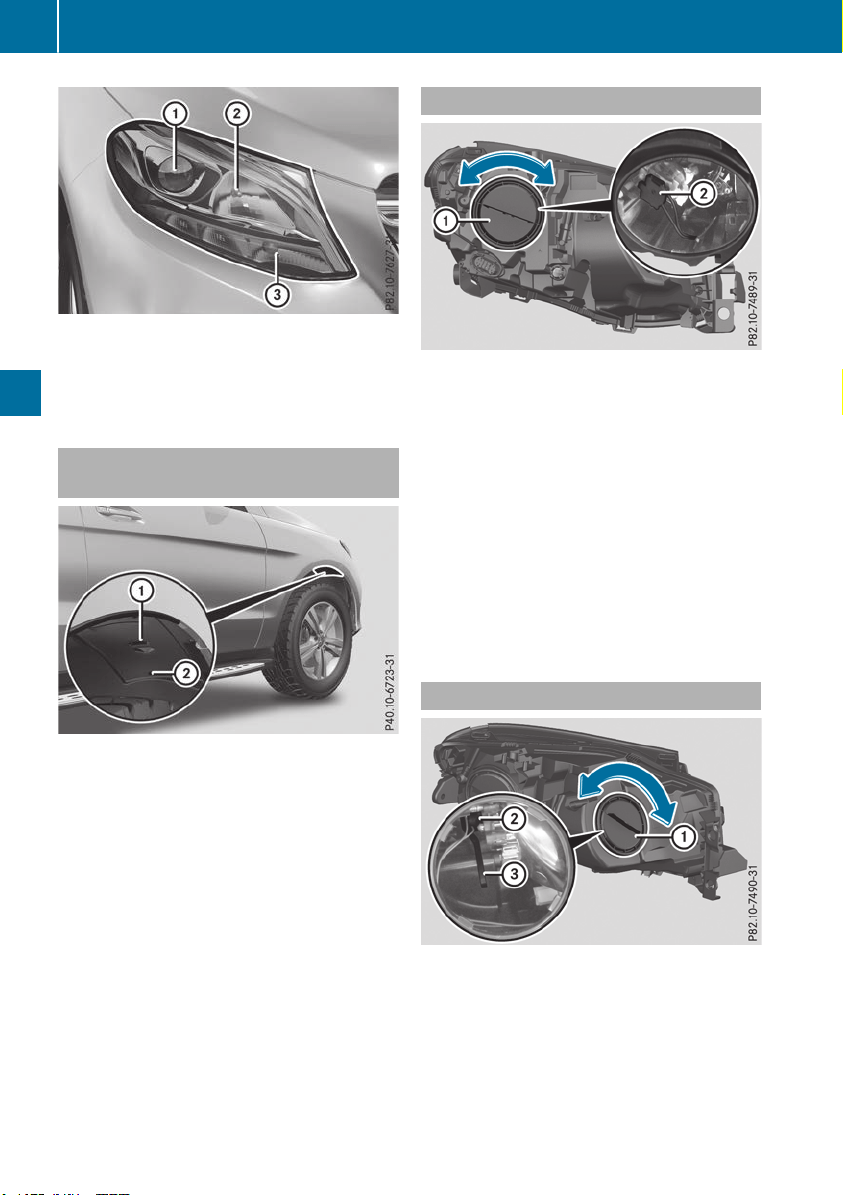
Halogen headlamps
:
Low-beam headlamp: H7 55 W
;
High-beam headlamp: H7 55 W
=
Turn signal: W 5 W BV
Removing and installing the cover in
the front wheel housing
You must remove the cover from the front wheel
housing before you can change the front bulbs.
X
To remove: switch off the lights.
X
Turn the front wheel inwards.
X
Remove securing pin ; using a suitable tool.
X
Slide cover : up and remove it.
X
To install: insert cover : again and slide it
down until it engages.
X
Insert securing pin ;.
Low-beam headlamps
X
Remove the cover in the front wheel housing
(Y page 116).
X
Turn housing cover : counter-clockwise and
remove it.
X
Turn bulb holder ; counter-clockwise and
pull out.
X
Pull the bulb out of bulb holder ;.
X
Insert new bulb into bulb holder ;.
X
Insert bulb holder ; and turn it clockwise.
X
Press on housing cover : and turn it to the
right.
X
Replace the cover in the front wheel housing
(Y page 116).
High-beam headlamps
X
Switch off the lights.
X
Open the hood.
X
Turn housing cover : counter-clockwise and
remove it.
X
Pull lever = upwards (headlamps on the left
in the direction of travel) or push it down-
wards (headlamps on the right in the direction
of travel) and remove bulb holder ;.
116
Replacing bulbs (vehicles with halogen headlamps)
Lights and windshield wipers
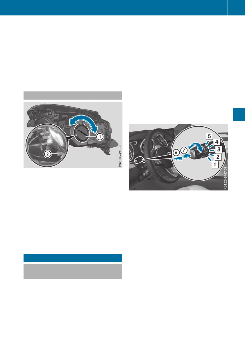
X
Remove the bulb from bulb holder ;.
X
Insert the new bulb into bulb holder ;.
X
Simultaneously push down on bulb holder ;
and push lever = downwards (headlamps on
the left in the direction of travel) or pull
upwards (headlamps on the right in the direc-
tion of travel).
X
Press on housing cover : and turn it clock-
wise.
Turn signals
X
Switch off the lights.
X
Open the hood.
X
Turn housing cover : counter-clockwise and
remove it.
X
Turn bulb holder ; counter-clockwise and
pull out.
X
Pull the bulb out of bulb holder ;.
X
Insert new bulb into bulb holder ;.
X
Insert bulb holder ; and turn it clockwise.
X
Press on housing cover : and turn it to the
right.
Windshield wipers
Switching the windshield wipers
on/off
!
Do not operate the windshield wipers when
the windshield is dry, as this could damage
the wiper blades. Moreover, dust that has col-
lected on the windshield can scratch the glass
if wiping takes place when the windshield is
dry.
If it is necessary to switch on the windshield
wipers in dry weather conditions, always use
washer fluid when operating the windshield
wipers.
!
If the windshield wipers leave smears on the
windshield after the vehicle has been washed
in an automatic car wash, wax or other resi-
dues may be the reason for this. Clean the
windshield using washer fluid after washing
the vehicle in an automatic car wash.
!
Intermittent wiping with rain sensor: due to
optical influences and the windshield becom-
ing dirty in dry weather conditions, the wind-
shield wipers may be activated inadvertently.
This could then damage the windshield wiper
blades or scratch the windshield.
For this reason, you should always switch off
the windshield wipers in dry weather.
Combination switch
1
$ Windshield wiper off
2
Ä Intermittent wipe, low (rain sensor set
to low sensitivity)
3
Å Intermittent wipe, high (rain sensor
set to high sensitivity)
4
° Continuous wipe, slow
5
¯ Continuous wipe, fast
B
í Single wipe
C
î To wipe with washer fluid
X
Switch on the ignition.
X
Turn the combination switch to the corre-
sponding position.
In the Ä or Å position, the appropriate
wiping frequency is set automatically according
to the intensity of the rain. In the Å position,
the rain sensor is more sensitive than in
the Ä position, causing the windshield wiper
to wipe more frequently.
Vehicles with MAGIC VISION CONTROL: the
washer fluid is fed through the wiper blades and
when wiping with washer fluid î the washer
fluid is emitted directly from the blades.
Windshield wipers
117
Lights and windshield wipers
Z
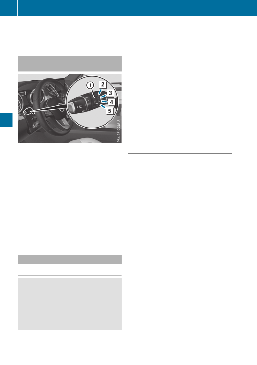
If the wiper blades are worn, the windshield will
no longer be wiped properly. This could prevent
you from observing the traffic conditions.
Switching the rear window wipers
on/off
Combination switch
:
è Rear window wiper switch
2
b Wipes with washer fluid
3
I Switches on intermittent wiping
4
0 Switches off intermittent wiping
5
b Wipes with washer fluid
X
Turn the SmartKey to position 1 or 2
(Y page 135).
X
Turn switch : on the combination switch to
the corresponding position.
When the rear window wiper is switched on,
the è symbol appears in the assistance
graphic in the instrument cluster. Further
information on the assistance graphic
(Y page 237).
Replacing the wiper blades
Important safety notes
G
WARNING
If the windshield wipers begin to move while
you are changing the wiper blades, you could
be trapped by the wiper arm. There is a risk of
injury.
Always switch off the windshield wipers and
ignition before changing the wiper blades.
!
To avoid damaging the wiper blades, make
sure that you touch only the wiper arm of the
wiper.
!
Never open the hood/tailgate if a wiper arm
has been folded away from the windshield/
rear window.
Never fold a windshield wiper arm without a
wiper blade back onto the windshield/rear
window.
Hold the windshield wiper arm firmly when
you change the wiper blade. If you release the
wiper arm without a wiper blade and it falls
onto the windshield/rear window, the wind-
shield/rear window may be damaged by the
force of the impact.
Mercedes-Benz recommends that you have
the wiper blades changed at a qualified spe-
cialist workshop.
Changing the windshield wiper blades
Moving the wiper arms to a vertical posi-
tion
On vehicles without KEYLESS-GO:
X
Turn the SmartKey to position u in the igni-
tion lock (Y page 135).
X
Set the windshield wiper to position ° on
the combination switch.
X
Turn the SmartKey to position 1 in the igni-
tion lock (Y page 135).
X
As soon as the wiper arms are vertical to the
hood, turn the SmartKey to position u in the
ignition lock (Y page 135).
X
Remove the SmartKey.
X
Fold the wiper arms away from the windshield
until you feel them snap into place.
On vehicles with KEYLESS-GO:
X
Switch off the engine.
X
Remove your foot from the brake pedal.
X
Set the windshield wiper to the ° position.
X
Press the Start/Stop button repeatedly until
the windshield wiper starts.
X
When the wiper arms are vertical to the hood,
press the Start/Stop button repeatedly until
the windshield wiper stops.
X
Fold the wiper arms away from the windshield
until you feel them snap into place.
118
Windshield wipers
Lights and windshield wipers
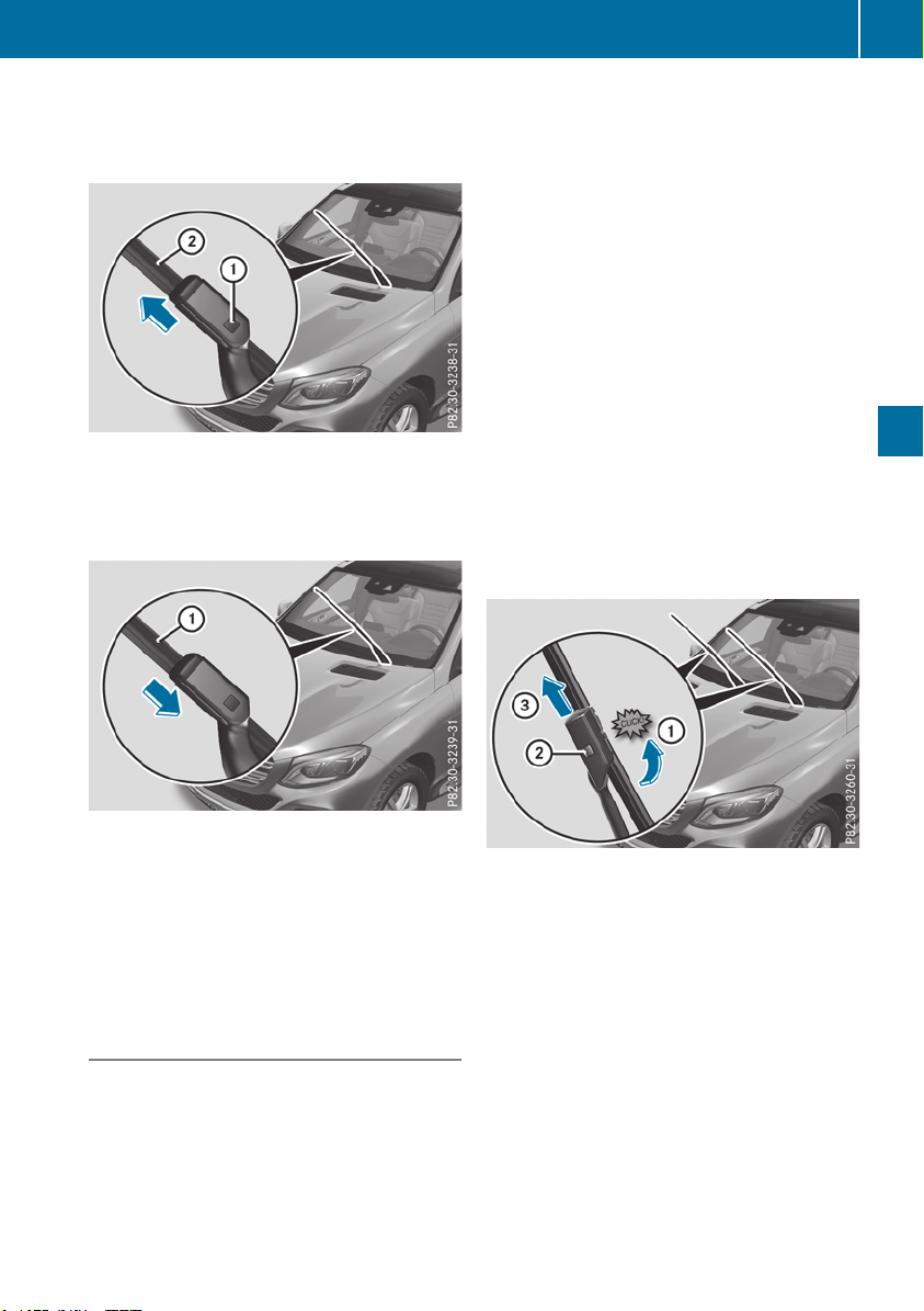
Removing the wiper blades
X
Remove the SmartKey from the ignition lock.
X
Fold the wiper arm away from the windshield.
X
Firmly press release knob : and pull wiper
blade ; upwards from the wiper arm in the
direction of the arrow.
Installing the wiper blades
X
Position new wiper blade : in the retainer on
the wiper arm and slide it into place in the
direction of the arrow.
The wiper blade audibly engages.
X
Make sure that the wiper blade is seated cor-
rectly.
X
Fold the wiper arm back onto the windshield.
Replacing the wiper blades (MAGIC
VISION CONTROL)
Moving the wiper arms to a vertical posi-
tion
On vehicles without KEYLESS-GO:
X
Turn the SmartKey to position u in the igni-
tion lock (Y page 135).
X
Set the windshield wiper to position ° on
the combination switch.
X
Turn the SmartKey to position 1 in the igni-
tion lock (Y page 135).
X
As soon as the wiper arms are vertical to the
hood, turn the SmartKey to position u in the
ignition lock (Y page 135).
X
Remove the SmartKey.
X
Fold the wiper arms away from the windshield
until you feel them snap into place.
On vehicles with KEYLESS-GO:
X
Switch off the engine.
X
Remove your foot from the brake pedal.
X
Set the windshield wiper to the ° position.
X
Press the Start/Stop button repeatedly until
the windshield wiper starts.
X
When the wiper arms are vertical to the hood,
press the Start/Stop button repeatedly until
the windshield wiper stops.
X
Fold the wiper arms away from the windshield
until you feel them snap into place.
Removing a wiper blade
X
To bring the wiper blade into position to
be removed: hold the wiper arm firmly with
one hand. With the other hand, turn the wiper
blade in the direction of arrow : beyond the
point of resistance.
The wiper blade engages in the removal posi-
tion with an audible click.
X
To remove a wiper blade: firmly press
release knob ; and pull the wiper blade
upwards =.
Windshield wipers
119
Lights and windshield wipers
Z
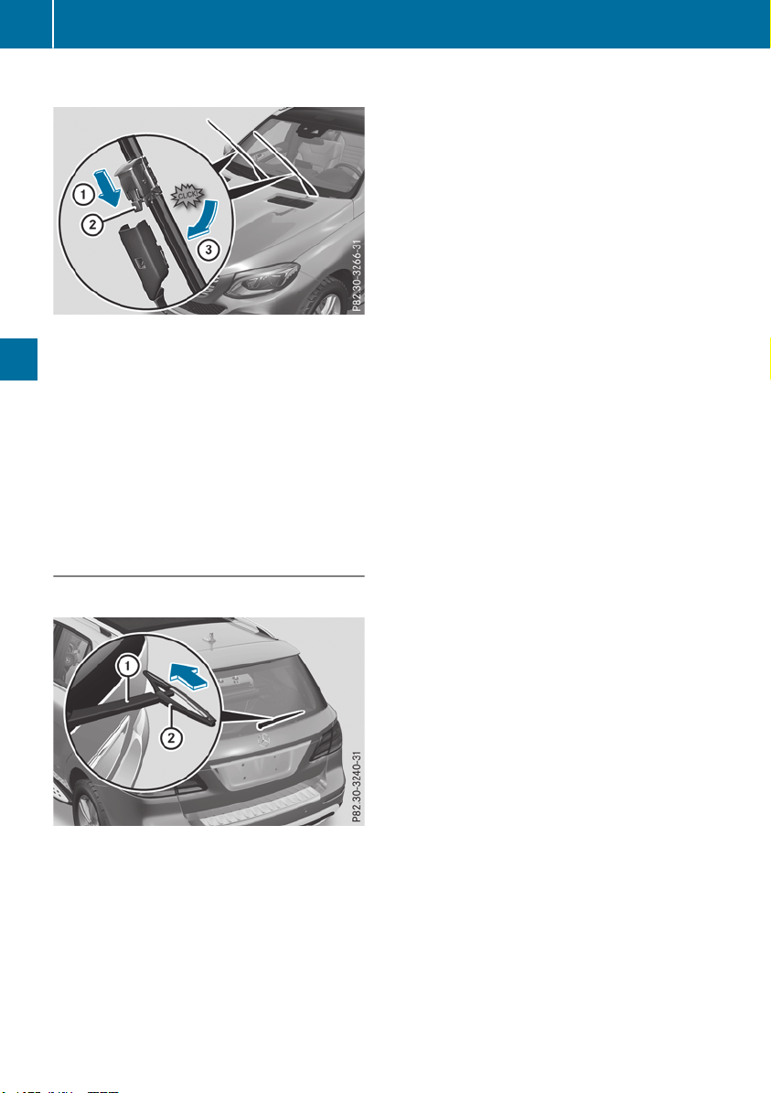
Installing the wiper blades
X
Push the new wiper blade in the direction of
arrow : onto the wiper arm until lug ;
engages.
X
Push the wiper blade out of the removal posi-
tion in the direction of arrow = beyond the
point of resistance.
The wiper blade disengages with an audible
click and is freely movable again.
X
Make sure that the wiper blade is seated cor-
rectly.
X
Fold the wiper arm back onto the windshield.
Replacing the rear window wiper blade
Removing a wiper blade
X
Remove the SmartKey from the ignition lock.
X
Fold wiper arm : away from the rear window
until it engages.
X
Position wiper blade ; at a right angle to
wiper arm :.
X
Hold wiper arm : and press wiper blade ;
in the direction of the arrow until it releases.
X
Remove wiper blade ;.
Installing a wiper blade
X
Place new wiper blade ; onto wiper arm :.
X
Hold wiper arm : and press wiper blade ;
in the opposite direction to the arrow until it
engages.
X
Make sure that wiper blade ; is seated cor-
rectly.
X
Position wiper blade ; parallel to wiper
arm :.
X
Fold wiper arm : back onto the rear window.
120
Windshield wipers
Lights and windshield wipers

Problems with the windshield wipers
Problem
Possible causes/consequences and MM Solutions
The windshield wipers
are jammed.
Leaves or snow, for example, may be obstructing the windshield wiper
movement. The wiper motor has been deactivated.
X
For safety reasons, you should remove the SmartKey from the igni-
tion lock.
or
X
Switch off the engine using the Start/Stop button and open the
driver's door.
X
Remove the cause of the obstruction.
X
Switch the windshield wipers back on.
The windshield wipers
fail completely.
The windshield wiper drive is malfunctioning.
X
Select another wiper speed on the combination switch.
X
Have the windshield wipers checked at a qualified specialist work-
shop.
Windshield wipers
121
Lights and windshield wipers
Z

Overview of climate control systems
General notes
Observe the settings recommended on the fol-
lowing pages. The windows could otherwise fog
up.
To prevent the windows from fogging up:
R
Switch off climate control only briefly
R
Switch on air-recirculation mode only briefly
R
Switch on the cooling with air dehumidifica-
tion function
R
Activate the "Windshield defrosting" function
briefly, if required
Climate control regulates the temperature and
the humidity in the vehicle interior and filters
undesirable substances out of the air.
The "Cooling with air dehumidification" function
is only available when the engine is running.
Optimum climate control is only achieved with
the side windows and roof closed.
The residual heat function can only be activated
or deactivated with the ignition switched off
(Y page 131).
i
Ventilate the vehicle for a brief period during
warm weather, e.g. using the convenience
opening feature (Y page 89). This will speed
up the cooling process and the desired inte-
rior temperature will be reached more
quickly.
If you start the engine using your smartphone,
the last selected climate control setting is reac-
tivated (Y page 137).
i
The integrated filter filters out most parti-
cles of dust and soot and completely filters
out pollen. It also reduces gaseous pollutants
and odors. A clogged filter reduces the
amount of air supplied to the vehicle interior.
Depending on the operating conditions and
environmental influences, the interval for
replacing the filter may be shorter than speci-
fied.
i
Vehicles with ionization of the interior
air with air filter: in addition to ionization,
the vehicle has an air filter with anti-allergenic
properties that contribute to improved air fil-
tration.
i
It is possible that under certain circumstan-
ces the residual heat function may be activa-
ted automatically an hour after the SmartKey
has been removed in order to dry the auto-
matic climate control. The vehicle is then ven-
tilated for 30 minutes.
i
Plug-in hybrid vehicles: observe the notes
on climate control in the separate operating
instructions.
122
Overview of climate control systems
Climate control
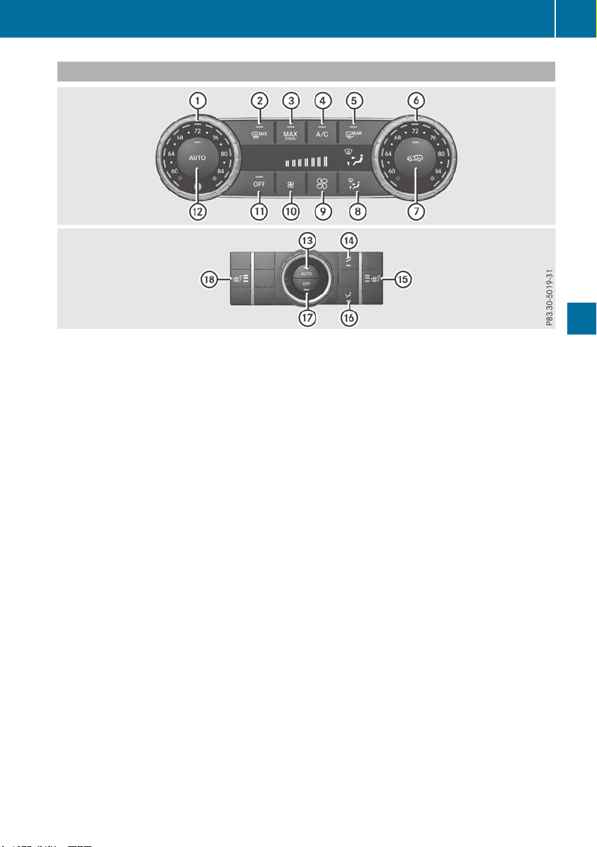
Control panel for dual-zone automatic climate control
USA only
Front control panel
:
Sets the temperature, left (Y page 128)
;
Defrosts the windshield (Y page 129)
=
Switches the maximum cooling MAX COOL on or off (Y page 130)
?
Switches cooling with air dehumidification on/off (Y page 127)
A
Switches the rear window defroster on/off (Y page 130)
B
Sets the temperature, right (Y page 128)
C
Switches air-recirculation mode on/off (Y page 131)
D
Sets the air distribution (Y page 129)
E
Increases the airflow (Y page 129)
F
Reduces the airflow (Y page 129)
G
Activates/deactivates climate control (Y page 127)
H
Sets climate control to automatic (Y page 128)
Rear control panel
I
Sets rear-compartment climate control to automatic (Y page 128)
J
Directs the air distribution through the rear air vents (Y page 129)
K
Switches the seat heating on the right-hand side on/off (Y page 101)
L
Directs the air distribution through the footwell vents (Y page 129)
M
Switches the rear climate control on/off (Y page 127)
N
Switches the seat heating on the left-hand side on/off (Y page 101)
Overview of climate control systems
123
Climate control
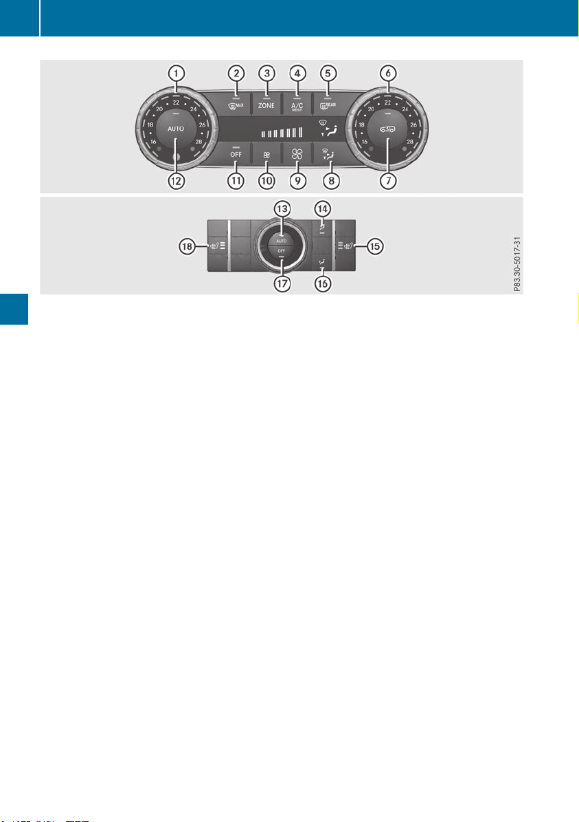
Canada only
Front control panel
:
Sets the temperature, left (Y page 128)
;
Defrosts the windshield (Y page 129)
=
Switches the ZONE function on/off (Y page 129)
?
Switches cooling with air dehumidification on/off (Y page 127)
Switches the residual heat on or off (Y page 131)
A
Switches the rear window defroster on/off (Y page 130)
B
Sets the temperature, right (Y page 128)
C
Switches air-recirculation mode on/off (Y page 131)
D
Sets the air distribution (Y page 129)
E
Increases the airflow (Y page 129)
F
Reduces the airflow (Y page 129)
G
Activates/deactivates climate control (Y page 127)
H
Sets climate control to automatic (Y page 128)
Rear control panel
I
Sets rear-compartment climate control to automatic (Y page 128)
J
Directs the air distribution through the rear air vents (Y page 129)
K
Switches the seat heating on the right-hand side on/off (Y page 101)
L
Directs the air distribution through the footwell vents (Y page 129)
M
Switches the rear climate control on/off (Y page 127)
N
Switches the seat heating on the left-hand side on/off (Y page 101)
124
Overview of climate control systems
Climate control
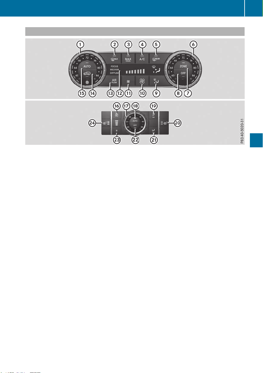
Control panel for 3-zone automatic climate control
USA only
Front control panel
:
Sets the temperature, left (Y page 128)
;
Defrosts the windshield (Y page 129)
=
Switches the maximum cooling MAX COOL on or off (Y page 130)
?
Switches cooling with air dehumidification on/off (Y page 127)
A
Switches the rear window defroster on/off (Y page 130)
B
Sets the temperature, right (Y page 128)
C
Switches the ZONE function on/off (Y page 129)
D
Activates/deactivates climate control (Y page 127)
E
Sets the air distribution (Y page 129)
F
Increases the airflow (Y page 129)
G
Reduces the airflow (Y page 129)
H
Display
I
Adjusts the climate mode settings (Y page 128)
J
Switches air-recirculation mode on/off (Y page 131)
K
Sets climate control to automatic (Y page 128)
Rear control panel
L
Increases the airflow (Y page 129)
M
Sets the temperature (Y page 128)
N
Sets rear-compartment climate control to automatic (Y page 128)
O
Directs the airflow through the rear air vents (Y page 129)
P
Switches the seat heating on the right-hand side on/off (Y page 101)
Q
Directs the airflow through the footwell vents (Y page 129)
R
Switches the rear climate control on/off (Y page 127)
S
Reduces the airflow (Y page 129)
T
Switches the seat heating on the left-hand side on/off (Y page 101)
Overview of climate control systems
125
Climate control
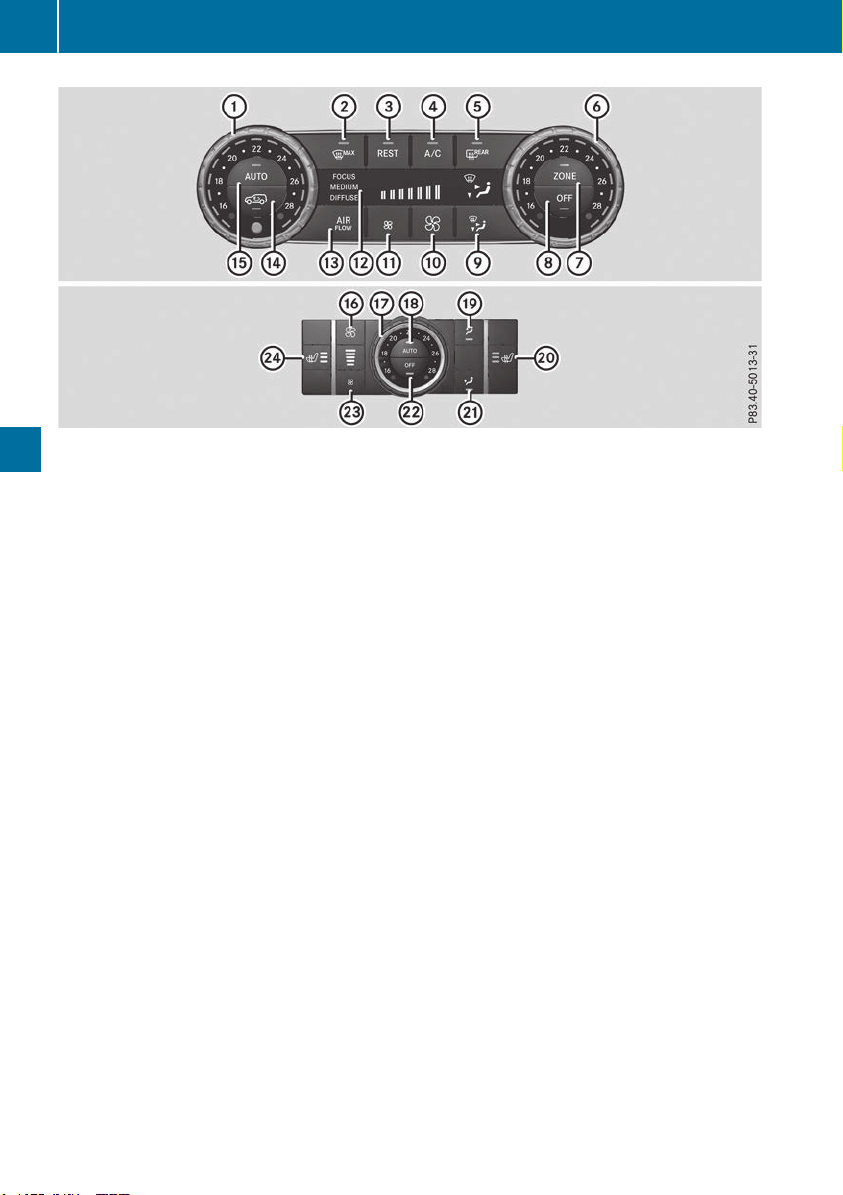
Canada only
Front control panel
:
Sets the temperature, left (Y page 128)
;
Defrosts the windshield (Y page 129)
=
Switches the residual heat on or off (Y page 131)
?
Switches cooling with air dehumidification on/off (Y page 127)
A
Switches the rear window defroster on/off (Y page 130)
B
Sets the temperature, right (Y page 128)
C
Switches the ZONE function on/off (Y page 129)
D
Activates/deactivates climate control (Y page 127)
E
Sets the air distribution (Y page 129)
F
Increases the airflow (Y page 129)
G
Reduces the airflow (Y page 129)
H
Display
I
Adjusts the climate mode settings (Y page 128)
J
Switches air-recirculation mode on/off (Y page 131)
K
Sets climate control to automatic (Y page 128)
Rear control panel
L
Increases the airflow (Y page 129)
M
Sets the temperature (Y page 128)
N
Sets rear-compartment climate control to automatic (Y page 128)
O
Directs the airflow through the rear air vents (Y page 129)
P
Switches the seat heating on the right-hand side on/off (Y page 101)
Q
Directs the airflow through the footwell vents (Y page 129)
R
Switches the rear climate control on/off (Y page 127)
S
Reduces the airflow (Y page 129)
T
Switches the seat heating on the left-hand side on/off (Y page 101)
126
Overview of climate control systems
Climate control

Optimum use of automatic climate
control
The following contains notes and recommenda-
tions on optimum use of the dual-zone auto-
matic climate control or 3-zone automatic cli-
mate control.
R
You can switch on climate control by using the
à and ¿ or à and Á buttons.
The indicator lamps in the à and
¿ buttons or the à and Á buttons
light up.
R
Vehicles with 3-zone automatic climate
control: in automatic mode, you can also use
the ñ button to set a climate mode
(FOCUS/MEDIUM/DIFFUSE). The MEDIUM
level is recommended.
R
Set the temperature to 72 ‡ (22 †).
R
Only use the "Windshield defrosting" function
briefly until the windshield is clear again.
R
Only use air-recirculation mode briefly, e.g. if
there are unpleasant outside odors or when in
a tunnel. The windows could otherwise fog up,
since no fresh air is drawn into the vehicle in
air-recirculation mode.
R
Vehicles with 3-zone automatic climate
control: use the ZONE function to adopt the
temperature settings on the driver's side for
the front-passenger side and the rear com-
partment as well. The indicator lamp above
the á button goes out.
R
Vehicles with 3-zone automatic climate
control: use the "residual heat" function if
you want to heat or ventilate the vehicle inte-
rior when the ignition is switched off. The
residual heat function can only be activated or
deactivated with the ignition switched off.
R
If you change the settings of the climate con-
trol system, the climate status display
appears for approximately three seconds at
the bottom of the screen in the multimedia
system display. You will see the current set-
tings of the various climate control functions.
During automatic engine switch-off, the climate
control system only operates at a reduced capa-
city. If you require the full climate control output,
you can switch off the ECO start/stop function
by pressing the ECO button (Y page 140).
Operating the climate control sys-
tems
Activating/deactivating climate con-
trol
General notes
When the climate control is switched off, the air
supply and air circulation are also switched off.
The windows could fog up. Therefore, switch off
climate control only briefly
Activate climate control primarily using the
à button (Y page 128).
In the rear compartment, you can also switch
climate control on and off using the à and
^ buttons.
Activating/deactivating
X
Turn the SmartKey to position 2 in the igni-
tion lock (Y page 135).
X
To activate: press the à button.
The indicator lamp in the à button lights
up. Airflow and air distribution are set to auto-
matic mode.
X
To deactivate: press the ^ button.
The indicator lamp in the ^ button lights
up.
Switching cooling with air dehumidi-
fication on/off
Activating/deactivating
X
To activate: press the ¿ or Á button.
The indicator lamp in the ¿ or Á button
lights up.
X
To deactivate: press the ¿ or Á but-
ton.
The indicator lamp in the ¿ or Á button
goes out. The "Cooling with air dehumidifica-
tion" function has a delayed switch-off fea-
ture.
Operating the climate control systems
127
Climate control

Problems with the "Cooling with air dehumidification" function
Problem
Possible causes/consequences and MM Solutions
The indicator lamp in the
¿ or Á button
flashes three times or
remains off. The "Cool-
ing with air dehumidifi-
cation" function cannot
be switched on.
Cooling with air dehumidification has been deactivated due to a mal-
function.
X
Visit a qualified specialist workshop.
Setting climate control to automatic
General notes
In automatic mode, the set temperature is main-
tained automatically at a constant level. The
system automatically regulates the temperature
of the dispensed air, the airflow and the air dis-
tribution.
The "Cooling with air dehumidification" function
is activated automatically in automatic mode.
In the rear compartment, you can also switch
climate control for the rear seats to automatic
mode using the à button.
Automatic control
X
Turn the SmartKey to position 2 in the igni-
tion lock (Y page 135).
X
Set the desired temperature.
X
To activate: press the à button.
The indicator lamp in the à button lights
up. Automatic air distribution and airflow are
activated.
X
To switch to manual mode: press the _
button.
3-zone automatic climate control: when auto-
matic mode is activated, you can select a cli-
mate mode (Y page 128).
Adjusting the climate mode settings
You can select the following climate mode set-
tings in automatic mode:
FOCUS high airflow, slightly cooler setting
MEDIUM medium airflow, standard setting
DIFFUSE low airflow, slightly warmer and draft-
free setting
X
Turn the SmartKey to position 2 in the igni-
tion lock (Y page 135).
X
Press the à button.
X
Press the ñ button repeatedly until the
desired climate mode appears in the display.
Setting the temperature
Dual-zone automatic climate control
Different temperatures can be set for the driv-
er's and front-passenger sides.
X
Turn the SmartKey to position 2 in the igni-
tion lock (Y page 135).
X
To increase or decrease: turn control : or
B counter-clockwise or clockwise
(Y page 123).
Only change the temperature setting in small
increments. Start at 72 ‡ (22 †).
3-zone automatic climate control
You can select different temperature settings
for the driver's and front-passenger sides as well
as for the rear compartment.
X
Turn the SmartKey to position 2 in the igni-
tion lock (Y page 135).
X
To increase or decrease temperature in
the front compartment: turn control : or
B counter-clockwise or clockwise
(Y page 125).
Only change the temperature setting in small
increments. Start at 72 ‡ (22 †).
X
To increase or reduce the temperature in
the rear compartment using the front con-
trol panel: press the á button.
The indicator lamp in the á button goes
out.
128
Operating the climate control systems
Climate control

The temperature setting for the driver's side
is adopted for the rear compartment and the
front-passenger side.
X
Turn thumbwheel : to the left or right
(Y page 125).
Only change the temperature setting in small
increments. Start at 72 ‡ (22 †).
X
To increase or decrease the rear compart-
ment temperature using the rear control
panel: turn control M counter-clockwise or
clockwise on the rear control panel
(Y page 125).
Only change the temperature setting in small
increments. Start at 72 ‡ (22 †).
Setting the air distribution
Air distribution settings
Front control panel
P
Directs the airflow through the center
vents
O
Directs air through the footwell air vents
S
Directs the airflow through the center
and footwell vents
¯
Directs air through the defroster vents
b
Directs the airflow through the defroster
and center vents (Canada only)
a
Directs air through the defroster and
footwell vents
_
Directs the airflow through the defroster,
center and footwell air vents (Canada
only)
Rear control panel
M
Directs the airflow through the rear cen-
ter and B-pillar air vents
O
Directs air through the footwell air vents
i
Using the rear control panel, you can also
activate both air distribution positions simul-
taneously. In order to do this, press both air
distribution buttons. The air is then routed
through all rear air vents.
i
Regardless of the air distribution setting,
airflow is always directed through the side air
vents. The side air vents can only be closed
when the controls on the side air vents are
turned downwards.
Setting
X
Turn the SmartKey to position 2 in the igni-
tion lock (Y page 135).
X
Press the _ button repeatedly until the
desired symbol appears in the display.
Setting the airflow
X
Turn the SmartKey to position 2 in the igni-
tion lock (Y page 135).
X
To increase: press the K button.
X
To reduce: press the I button.
i
You can use 3-zone automatic climate con-
trol to set the airflow in the rear compartment
separately.
Switching the ZONE function on/off
X
To activate: press the á button.
The indicator lamp above the á button
lights up.
Dual-zone automatic climate control: the tem-
perature setting for the driver's side is not
adopted for the front-passenger side.
3-zone automatic climate control: the tem-
perature setting for the driver's side is not
adopted for the front-passenger side and the
rear compartment.
X
To deactivate: press the á button.
The indicator lamp above the á button
goes out.
Dual-zone automatic climate control: the tem-
perature setting for the driver's side is adop-
ted for the front-passenger side.
3-zone automatic climate control: the tem-
perature setting for the driver's side is adop-
ted for the front-passenger side and the rear
compartment.
Defrosting the windshield
General notes
You can use this function to defrost the wind-
shield or to clear a fogged up windshield or front
side windows on the inside.
Switch off the "Windshield defrosting" function
as soon as the windshield is clear again.
Operating the climate control systems
129
Climate control

Activating/deactivating
X
Turn the SmartKey to position 2 in the igni-
tion lock (Y page 135).
X
To activate: press the ¬ button.
The indicator lamp in the ¬ button lights
up.
The climate control system switches to the
following settings:
R
high airflow
R
high temperature
R
air distribution to the windshield and front
side windows
R
air-recirculation mode off
X
To deactivate: press the ¬ button.
The indicator lamp in the ¬ button goes
out. The previously selected settings are
restored. Air-recirculation mode remains
deactivated.
MAX COOL maximum cooling
The MAX COOL function is only available in vehi-
cles for the USA.
MAX COOL is only operational when the engine
is running.
X
To activate: press the Ù button.
The indicator lamp in the Ù button lights
up.
X
To deactivate: press the Ù button.
The indicator lamp in the Ù button goes
out. The previously selected settings are
restored.
When you activate MAX COOL, climate control
switches to the following functions:
R
maximum cooling
R
maximum airflow
R
air-recirculation mode on
Removing condensation from the win-
dows
Windows fogged up on the inside
X
Activate the ¿ or Á cooling with air
dehumidification function.
X
Activate automatic mode Ã.
X
If the windows continue to fog up, activate the
"windshield defrosting" function
(Y page 129).
i
You should only select this setting until the
windshield is clear again.
Windows fogged up on the outside
X
Activate the windshield wipers.
X
Press the _ button repeatedly until the
P or O symbol appears in the display.
i
You should only select this setting until the
windshield is clear again.
i
If you clean the windows regularly, they do
not fog up so quickly.
Rear window defroster
General notes
The rear window defroster has a high current
draw. You should therefore switch it off as soon
as the rear window is clear. Otherwise, the rear
window defroster switches off automatically
after several minutes.
If the battery voltage is too low, the rear window
defroster may switch off.
Activating/deactivating
X
Turn the SmartKey to position 2 in the igni-
tion lock (Y page 135).
X
Press the ¤ button.
The indicator lamp in the ¤ button lights
up or goes out.
130
Operating the climate control systems
Climate control

Problems with the rear window defroster
Problem
Possible causes/consequences and MM Solutions
The rear window
defroster has deactiva-
ted prematurely or can-
not be activated.
The battery has not been sufficiently charged.
X
Switch off any consumers that are not required, e.g. reading lamps,
interior lighting or the seat heating.
When the battery is sufficiently charged, the rear window defroster
can be activated again.
Switching air-recirculation mode
on/off
General notes
You can deactivate the flow of fresh air if
unpleasant odors are entering the vehicle from
outside. The air already inside the vehicle will
then be recirculated.
If you switch on air-recirculation mode, the win-
dows can fog up more quickly, in particular at
low temperatures. Only use air-recirculation
mode briefly to prevent the windows from fog-
ging up.
Activating/deactivating
X
Turn the SmartKey to position 2 in the igni-
tion lock (Y page 135).
X
To activate: press the d button.
The indicator lamp in the d button lights
up.
i
In the event of high pollution levels (3-zone
automatic climate control only) or at high out-
side temperatures, air-recirculation mode is
automatically activated. When air-recircula-
tion mode is activated automatically, the indi-
cator lamp in the d button is not lit.
Outside air is added after about 30 minutes.
X
To deactivate: press the d button.
The indicator lamp in the d button goes
out.
i Air-recirculation mode deactivates auto-
matically:
R
after approximately five minutes at outside
temperatures below approximately 41 ‡
(5 †)
R
after approximately five minutes if cooling
with air dehumidification is deactivated
R
after approximately 30 minutes at outside
temperatures above approximately 41 ‡
(5 †) if the "Cooling with air dehumidifi-
cation" function is activated
Switching the residual heat on or off
General notes
The residual heat function is only available on
vehicles for Canada.
It is possible to make use of the residual heat of
the engine to continue heating the stationary
vehicle for up to 30 minutes after the engine has
been switched off. The heating time depends on
the set interior temperature.
Activating/deactivating
X
To activate: press the Ì or Á button.
The indicator lamp in the Ì or Á button
lights up.
i
The blower will run at a low speed regardless
of the airflow setting.
i
If you activate the residual heat function at
high temperatures, only the ventilation will be
activated. The blower runs at medium speed.
X
To deactivate: press the Ì or Á but-
ton.
The indicator lamp in the Ì or Á button
goes out.
Residual heat is deactivated automatically:
R
after approximately 30 minutes
R
when the ignition is switched on
R
if the battery voltage drops
Ionization
Ionization is used to purify the air in the vehicle
interior and attain an improved interior climate.
Operating the climate control systems
131
Climate control
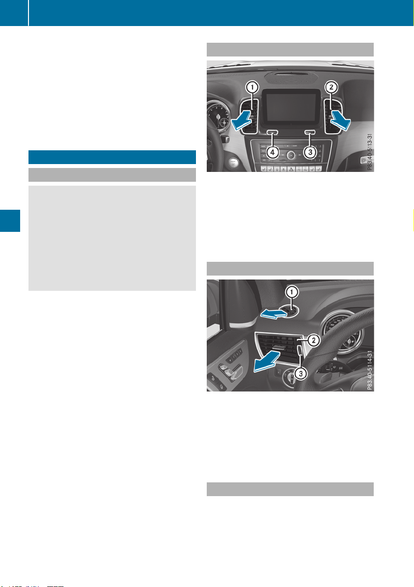
The ionization of the interior air is odorless and
cannot be perceived directly in the vehicle inte-
rior.
You can switch ionization on and off via the mul-
timedia system (see the Digital Operator's Man-
ual).
Ionization can only be operated when the auto-
matic climate control is switched on. The side air
vent on the driver's side must be open.
Setting the air vents
Important safety notes
G
WARNING
Very hot or very cold air can flow from the air
vents. This could result in burns or frostbite in
the immediate vicinity of the air vents. There
is a risk of injury.
Make sure that all vehicle occupants always
maintain a sufficient distance to the air out-
lets. If necessary, redirect the airflow to
another area of the vehicle interior.
In order to ensure the direct flow of fresh air
through the air vents into the vehicle interior,
please observe the following notes:
R
keep the air inlet grille on the hood and in the
engine compartment on the front-passenger
side free of blockages, such as ice, snow or
leaves.
R
never cover the air vents or air intake grilles in
the vehicle interior.
i
For virtually draft-free ventilation, adjust the
sliders of the air vents to the center position.
Setting the center air vents
:
Center air vent, left
;
Center air vent, right
=
Center vent thumbwheel, right
?
Center vent thumbwheel, left
X
To open or close: turn thumbwheels =
and ? to the left or right.
Setting the side air vents
Example
:
Side window defroster vent
;
Side air vent, left
=
Thumbwheel for side air vent
X
To open or close: turn thumbwheel = up or
down.
Setting the glove box air vent
!
Close the air vent when heating the vehicle.
At high outside temperatures, open the air
vent and activate the "cooling with air dehu-
midification" function. Otherwise, tempera-
ture-sensitive items stored in the glove box
could be damaged.
132
Setting the air vents
Climate control
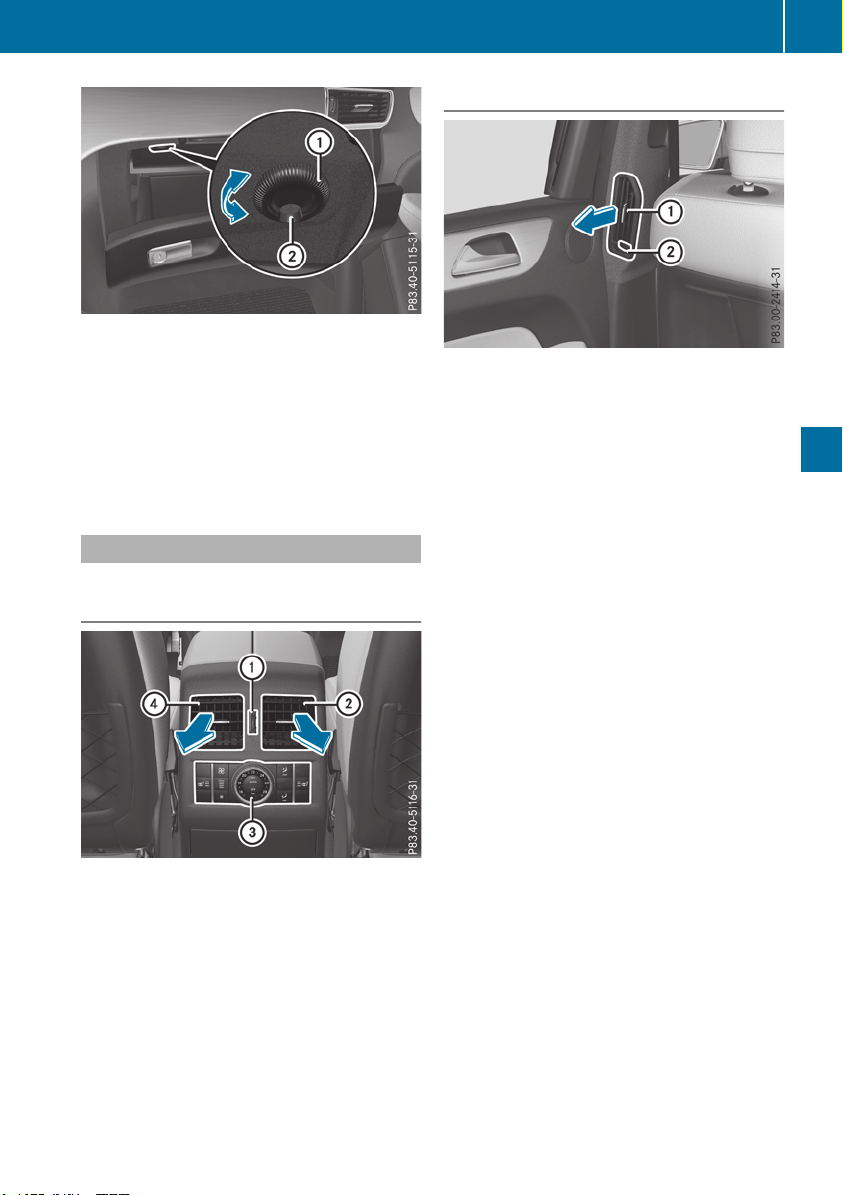
:
Air vent control
;
Air vent
When the climate control system is activated,
the glove box can be ventilated, for instance to
cool its contents. The level of airflow depends on
the airflow and air distribution settings.
X
To open or close: turn thumbwheel : to the
right or left.
Setting the rear air vents
Setting the center vents in the rear com-
partment
Example: center vents with rear control panel
:
Rear-compartment air vent thumbwheel
;
Rear-compartment air vent, right
=
Rear control panel
?
Rear-compartment air vent, left
X
To open or close: turn thumbwheel : up or
down.
Setting the B-pillar air vent
:
B-pillar air vent
;
Thumbwheel for B-pillar air vent
X
To open or close: turn thumbwheel ; to the
left or right.
Setting the air vents
133
Climate control
Z

Notes on breaking-in a new vehicle
Important safety notes
The sensor system of some driving and driving
safety systems adjusts automatically while a
certain distance is being driven after the vehicle
has been delivered or after repairs. Full system
effectiveness is not reached until the end of this
teach-in procedure.
New and replaced brake pads and discs only
reach their optimum braking effect after several
hundred kilometers of driving. Compensate for
this by applying greater force to the brake pedal.
The first 1000 miles (1500 km)
The more you look after the engine when it is
new, the more satisfied you will be with its per-
formance in the future.
R
You should therefore drive at varying vehicle
and engine speeds for the first 1000 miles
(1500 km).
R
Avoid heavy loads, e.g. driving at full throttle,
during this period.
R
Change gear in good time, before the tach-
ometer needle is Ô of the way to the red area
of the tachometer.
R
Do not manually shift to a lower gear to brake
the vehicle.
R
Try to avoid depressing the accelerator pedal
beyond the point of resistance (kickdown).
Additional breaking-in notes for Mercedes-AMG
vehicles:
R
Do not drive faster than 85 mph (140 km/h)
for the first 1,000 miles (1,500 km).
R
Only allow the engine to reach a maximum
engine speed of 4,500 rpm briefly.
R
Change gear in good time.
R
Ideally, for the first 1,000 miles (1,500 km),
drive in the Comfort drive program.
After 1000 miles (1500 km), you can increase
the engine speed gradually and accelerate the
vehicle to full speed.
You should also observe these notes on break-
ing in if the engine or parts of the drive train on
your vehicle have been replaced.
Always observe the maximum permissible
speed.
Driving
Important safety notes
G
WARNING
Objects in the driver's footwell can restrict the
pedal travel or obstruct a depressed pedal.
The operating and road safety of the vehicle is
jeopardized. There is a risk of an accident.
Make sure that all objects in the vehicle are
stowed correctly, and that they cannot enter
the driver's footwell. Install the floormats
securely and as specified in order to ensure
sufficient clearance for the pedals. Do not use
loose floormats and do not place floormats on
top of one another.
G
WARNING
Unsuitable footwear can hinder correct usage
of the pedals, e.g.:
R
shoes with thick soles
R
shoes with high heels
R
slippers
There is a risk of an accident.
Wear suitable footwear to ensure correct
usage of the pedals.
G
WARNING
If you switch off the ignition while driving,
safety-relevant functions are only available
with limitations, or not at all. This could affect,
for example, the power steering and the brake
boosting effect. You will require considerably
more effort to steer and brake. There is a risk
of an accident.
Do not switch off the ignition while driving.
G
WARNING
If the parking brake has not been fully
released when driving, the parking brake can:
R
overheat and cause a fire
R
lose its hold function.
There is a risk of fire and an accident. Release
the parking brake fully before driving off.
134
Driving
Driving and parking
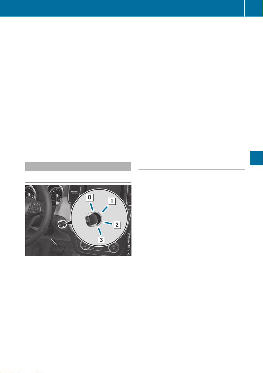
!
Do not warm up the engine while stationary.
Pull away immediately. Avoid high engine
speeds and full throttle until the engine has
reached its operating temperature.
In vehicles with automatic transmission,
engage positions P and R only when the vehi-
cle is stationary.
Where possible, avoid spinning the drive
wheels when pulling away on slippery roads.
You could otherwise damage the drive train.
!
Mercedes-AMG vehicles: at low engine oil
temperatures below 68 ‡ (+20 †), the max-
imum engine speed is restricted in order to
protect the engine. To protect the engine and
maintain smooth engine operation, avoid driv-
ing at full throttle when the engine is cold.
Plug-in hybrid: be sure to read the separate
Operator's Manual. Otherwise, you may not rec-
ognize dangers.
Key positions
SmartKey
g
To remove the SmartKey
1
Power supply for some consumers, such as
the windshield wipers
2
Ignition (power supply for all consumers)
and drive position
3
To start the engine
As soon as the ignition is switched on, all the
indicator lamps in the instrument cluster light
up. Further information on situations where an
indicator lamp either fails to go out after starting
the engine or lights up while driving
(Y page 276).
If the SmartKey is in position u in the ignition
lock for a longer period, it can no longer be
turned in the ignition lock. The steering is then
locked. To unlock, remove the SmartKey and
reinsert it into the ignition lock.
The steering is locked when you remove the
SmartKey from the ignition lock.
X
Remove the SmartKey when the engine is
switched off.
The starter battery could otherwise be dis-
charged.
If you cannot turn the SmartKey in the ignition
lock, the starter battery may not be charged
sufficiently.
X
Check the starter battery and charge it if nec-
essary (Y page 342).
or
X
Jump-start the vehicle (Y page 343).
i
The SmartKey can be turned in the ignition
lock even if it is not the correct SmartKey for
the vehicle. The ignition is not switched on.
The engine cannot be started.
KEYLESS-GO
General notes
Vehicles with KEYLESS-GO are equipped with a
SmartKey featuring an integrated KEYLESS-GO
function and a detachable Start/Stop button.
A check which periodically establishes a radio
connection between the vehicle and the Smart-
Key determines whether a valid SmartKey is in
the vehicle. This occurs, for example, when
starting the engine.
When you insert the Start/Stop button into the
ignition lock, the system needs approximately
two seconds recognition time. You can then use
the Start/Stop button.
Pressing the Start/Stop button several times in
succession corresponds to the different Smart-
Key positions in the ignition lock. This is only the
case if you are not depressing the brake pedal.
If you depress the brake pedal and press the
Start/Stop button, the engine starts immedi-
ately.
To start the vehicle without actively using the
SmartKey:
R
the Start/Stop button must be inserted in the
ignition lock
R
the SmartKey must be in the vehicle
R
the vehicle must not be locked with the
SmartKey or KEYLESS-GO (Y page 78).
Driving
135
Driving and parking
Z
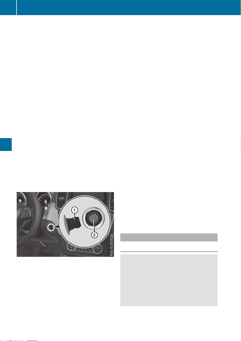
Do not keep the SmartKey:
R
with electronic devices, e.g. a mobile phone
or another SmartKey
R
with metallic objects, e.g. coins or metal foil
R
inside metallic objects, e.g. a metal case
This can impair the functionality of the KEY-
LESS-GO key.
Do not keep the KEYLESS-GO key in the tem-
perature-controlled cup holder (Y page 305).
Otherwise, the KEYLESS-GO key will not be rec-
ognized.
If you lock the vehicle with the SmartKey remote
control or with KEYLESS-GO, after a short time:
R
you will not be able to switch on the ignition
with the Start/Stop button
R
you will not be able to start the engine with the
Start/Stop button until the vehicle is
unlocked again
If you lock the vehicle centrally using the button
on the front door (Y page 83), you can continue
to start the engine with the Start/Stop button.
The engine can be switched off while the vehicle
is in motion by pressing and holding the Start/
Stop button for three seconds. This function
operates independently of the ECO start/stop
automatic engine switch-off function.
Key positions with KEYLESS-GO
:
Start/Stop button
;
Ignition lock
As soon as the ignition is switched on, all the
indicator lamps in the instrument cluster light
up. Further information on situations where an
indicator lamp either fails to go out after starting
the engine or lights up while driving
(Y page 276).
If Start/Stop button : has not yet been
pressed, this corresponds to the SmartKey
being removed from the ignition.
X
To switch on the power supply: press
Start/Stop button : once.
The power supply is switched on. You can now
activate the windshield wipers, for example.
The power supply is switched off again if:
R
the driver's door is opened and
R
you press Start/Stop : button twice when in
this position
X
To switch on the ignition: press Start/Stop
button : twice.
The ignition is switched on.
If you press Start/Stop button : once when
in this position, the ignition is deactivated
again.
Removing the Start/Stop button
You can remove the Start/Stop button from the
ignition lock and start the vehicle as normal
using the SmartKey.
It is possible to switch between KEYLESS-GO
mode and key operation only when the trans-
mission is in position j.
X
Remove Start/Stop button : from ignition
lock ;.
You do not have to remove the Start/Stop but-
ton from the ignition lock when you leave the
vehicle. You should, however, always take the
SmartKey with you when leaving the vehicle. As
long as the SmartKey is in the vehicle:
R
the vehicle can be started using the Start/
Stop button
R
the electrically powered equipment can be
operated
Starting the engine
Important safety notes
G
WARNING
If children are left unsupervised in the vehicle,
they could:
R
open the doors, thus endangering other
people or road users.
R
get out and disrupt traffic.
R
operate the vehicle's equipment.
136
Driving
Driving and parking

Additionally, children could set the vehicle in
motion if, for example, they:
R
release the parking brake.
R
shifting the automatic transmission out of
park position P
R
Start the engine.
There is a risk of an accident and injury.
When leaving the vehicle, always take the
SmartKey with you and lock the vehicle. Never
leave children or animals unattended in the
vehicle. Always keep the SmartKey out of
reach of children.
G
WARNING
Combustion engines emit poisonous exhaust
gases such as carbon monoxide. Inhaling
these exhaust gases leads to poisoning. There
is a risk of fatal injury. Therefore never leave
the engine running in enclosed spaces with-
out sufficient ventilation.
G
WARNING
Flammable materials introduced through
environmental influence or by animals can
ignite if in contact with the exhaust system or
parts of the engine that heat up. There is a risk
of fire.
Carry out regular checks to make sure that
there are no flammable foreign materials in
the engine compartment or in the exhaust
system.
General notes
Vehicles with a gasoline engine: the catalytic
converter is preheated for up to 30 seconds
after a cold start. The sound of the engine may
change during this time.
Automatic transmission
X
Shift the transmission to position j
(Y page 144).
The transmission position indicator on the
multifunction display shows j
(Y page 145).
i
You can start the engine in transmission
position j and i.
Starting procedure with the SmartKey
X
To start a diesel engine: turn the SmartKey
to position 2 in the ignition lock
(Y page 135).
The % indicator lamp on the instrument
cluster lights up.
X
Turn the SmartKey to position 3 in the igni-
tion lock (Y page 135) and release it as soon
as the engine is running.
i
Vehicles with a diesel engine: you can
start the engine without preglow if the engine
is warm.
Using KEYLESS-GO to start the engine
The Start/Stop button can be used to start the
vehicle without inserting the SmartKey into the
ignition lock. The Start/Stop button must be
inserted in the ignition lock and the SmartKey
must be in the vehicle. This mode for starting the
engine operates independently of the ECO
start/stop automatic engine start function.
X
Depress the brake pedal and keep it
depressed.
X
Press the Start/Stop button once
(Y page 135).
Vehicles with a gasoline engine: the engine
starts.
Vehicles with a diesel engine: preglow is
activated and the engine starts.
Starting procedure via smartphone
Observe the important safety notes on starting
the engine (Y page 136).
You can also start your engine via your smart-
phone from outside the vehicle. In this case, the
previously selected climate control setting is
activated. In this way you can cool or heat the
interior of the vehicle before starting the jour-
ney.
Only start the engine via your smartphone if it is
safe to start and run the engine where your vehi-
cle is parked.
Observe the legal stipulations in the area where
your vehicle is parked. Engine start via smart-
phone may be limited to certain countries or
regions.
Driving
137
Driving and parking
Z

You can execute a maximum of two consecutive
starting attempts via your smartphone. If you
insert the SmartKey into the ignition lock, you
can carry out two more starting attempts.
Once you have started the engine, you can
switch the engine off via your smartphone at any
time.
You can only start the engine via your smart-
phone if:
R
the SmartKey is in the ignition lock
R
park position j is selected
R
the accelerator pedal is not depressed
R
the anti-theft alarm system is not activated
R
the panic alarm is not activated
R
the hazard warning lamps are switched off
R
the hood is closed
R
the doors are closed and locked
R
the windows and sliding sunroof are closed
Also make sure that:
R
the fuel tank is sufficiently filled
R
the starter battery has been sufficiently
charged
G
WARNING
Limbs could be crushed or trapped if the
engine is started unintentionally during ser-
vice or maintenance work. There is a risk of
injury.
Always secure the engine against uninten-
tional starting before carrying out mainte-
nance or repair work.
Make sure that the engine cannot be started via
your smartphone before carrying out mainte-
nance or repairs. You can prevent an engine
start via your smartphone if you:
R
switch on the hazard warning lamps
R
do not lock the doors
R
open the hood
Pulling away
General notes
G
WARNING
If the engine speed is above the idling speed
and you engage transmission position 7
or C, the vehicle could pull away sud-
denly. There is a risk of an accident.
When engaging transmission position 7 or
C, always firmly depress the brake pedal
and do not simultaneously accelerate.
Depress the accelerator carefully when pulling
away.
The vehicle locks centrally once you have pulled
away. The locking knobs in the doors drop down.
You can open the doors from the inside at any
time.
You can also deactivate the automatic locking
feature (Y page 240).
It is possible to shift the transmission from posi-
tion j to the desired position only if you
depress the brake pedal. Only then is the park-
ing lock released. If you do not depress the
brake pedal, the DIRECT SELECT lever can still
be moved but the parking lock remains
engaged.
i
Upshifts take place at higher engine speeds
after a cold start. This helps the catalytic con-
verter to reach its operating temperature
more quickly.
Information on the automatic release of the
electric parking brake (Y page 158).
Pulling away with a trailer
To ensure that you do not roll backwards when
pulling away on an uphill slope, engage the elec-
tric parking brake.
X
Press and hold handle :.
The electric parking brake continues to brake
and prevent the vehicle from rolling back-
wards.
138
Driving
Driving and parking
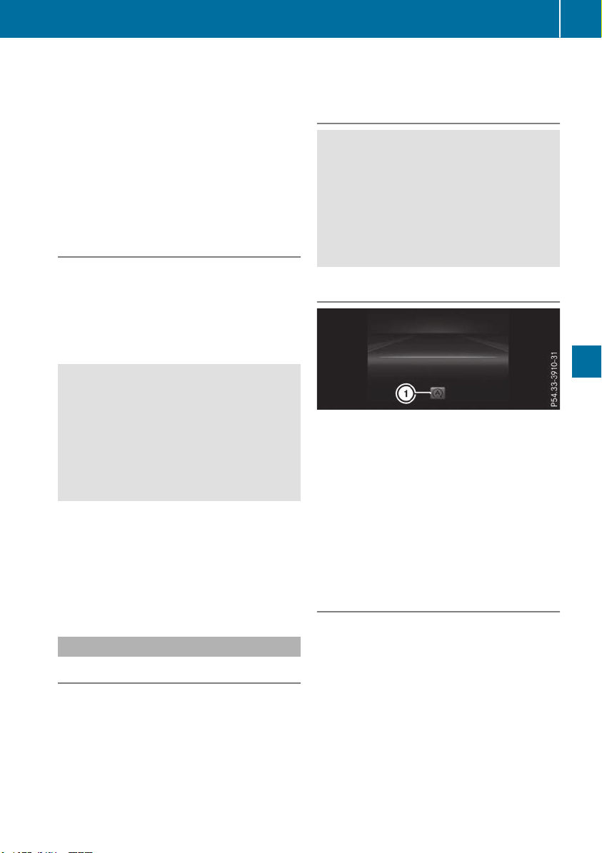
The red F (USA only) or ! (Canada
only) indicator lamp in the instrument cluster
remains on.
X
Depress the accelerator pedal.
X
As soon as the vehicle/trailer combination is
held by the driving force of the engine, release
lever :.
the electric parking brake is released.
The red F (USA only) or ! (Canada
only) indicator lamp in the instrument cluster
goes out.
Hill start assist
Hill start assist helps you when pulling away
forward or in reverse on an uphill gradient. It
holds the vehicle for a short time after you have
removed your foot from the brake pedal. This
gives you enough time to move your foot from
the brake pedal to the accelerator pedal and to
depress it before the vehicle begins to roll.
G
WARNING
After a short time, hill start assist will no lon-
ger brake your vehicle and it could roll away.
There is a risk of an accident and injury.
Therefore, quickly move your foot from the
brake pedal to the accelerator pedal. Never
leave the vehicle when it is held by hill start
assist.
Hill start assist is not active if:
R
you are pulling away on a level road or on a
downhill gradient.
R
the transmission is in position i.
R
the electric parking brake is applied.
R
ESP
®
is malfunctioning.
ECO start/stop function
Introduction
Plug-in hybrid: observe the notes on the ECO
start/stop function in the separate operating
instructions.
The ECO start/stop function switches the
engine off automatically if the vehicle is stopped
under certain conditions.
The engine starts automatically when the driver
wants to pull away again. The ECO start/stop
function thereby helps you to reduce the fuel
consumption and emissions of your vehicle.
Important safety notes
G
WARNING
If the engine is switched off automatically and
you exit the vehicle, the engine is restarted
automatically. The vehicle may begin moving.
There is a risk of accident and injury.
If you wish to exit the vehicle, always turn off
the ignition and secure the vehicle against
rolling away.
General notes
:
ECO start/stop display
The ECO start/stop function is activated when-
ever you start the engine using the SmartKey or
the Start/Stop button.
If the engine has been switched off automati-
cally by the ECO start/stop function, the è
ECO symbol is shown in the multifunction dis-
play.
Mercedes-AMG vehicles: the ECO start/stop
function is only available in drive programs
Comfort and Slippery.
Automatic engine switch-off
If the vehicle is braked to a standstill with the
transmission in h or i, the ECO start/stop
function will switch off the engine automatically.
The ECO start/stop function is operational
when:
R
the indicator lamp in the ECO button is lit
green
R
the Sport Plus drive program is not selected
(Mercedes-AMG GLE 43 4MATIC)
R
the Sport Plus or Sport drive program is not
selected (Mercedes-AMG vehicles)
R
no Off-road program has been selected
Driving
139
Driving and parking
Z
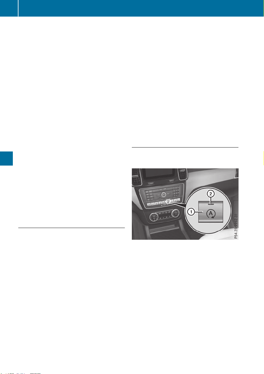
R
the outside temperature and the atmospheric
air pressure is within the range that is suitable
for the system
R
the engine is at normal operating temperature
R
the set temperature for the vehicle interior
has been reached
R
the battery is sufficiently charged
R
the system detects that the windshield is not
fogged up when the air-conditioning system is
switched on
R
the hood is closed
R
the driver's door is closed and the driver's
seat belt is fastened
All of the vehicle's systems remain active when
the engine is stopped automatically.
The HOLD function can also be activated if the
engine has been switched off automatically. It is
then not necessary to continue applying the
brakes during the automatic stop phase. When
you depress the accelerator pedal, the engine
starts automatically and the braking effect of
the HOLD function is deactivated.
All vehicles (except Mercedes-AMG vehi-
cles): automatic engine switch-off can take
place a maximum of four times in a row (initial
stop, then three subsequent stops).
Mercedes-AMG vehicles: the number of con-
secutive automatic engine switch-offs is unlimi-
ted.
Automatic engine start
The engine starts automatically if:
R
you switch off the ECO start/stop function by
pressing the ECO button
R
in transmission position h or i, the brake
pedal is released and the HOLD function is not
active
R
you depress the accelerator pedal
R
you engage reverse gear k
R
you move the transmission out of position j
R
you switch to the Sport Plus drive program
(Mercedes-AMG GLE 43 4MATIC)
R
you switch to the Sport Plus or Sport drive
program (Mercedes-AMG vehicles)
R
you activate manual gearshifting (Mercedes-
AMG vehicles)
R
you switch to the Offroad drive program
(vehicles without Off-road Engineering Pack-
age)
R
you switch to the Offroad or Offroad Plus
drive program (vehicles with Off-road Engi-
neering Package)
R
you unfasten your seat belt or open the driv-
er's door
R
the vehicle starts to roll
R
the brake system requires this
R
the temperature in the vehicle interior devi-
ates from the set range
R
the system detects moisture on the wind-
shield when the air-conditioning system is
switched on
R
the battery's condition of charge is too low
Shifting the transmission to position j does
not start the engine.
Deactivating or activating the ECO
start/stop function
All vehicles (except Mercedes-AMG vehi-
cles)
X
To deactivate: press ECO button :.
Indicator lamp ; goes out.
X
To activate: press ECO button :.
Indicator lamp ; lights up.
If indicator lamp ; is off, the ECO start/stop
function has been deactivated manually or as
the result of a malfunction.
140
Driving
Driving and parking
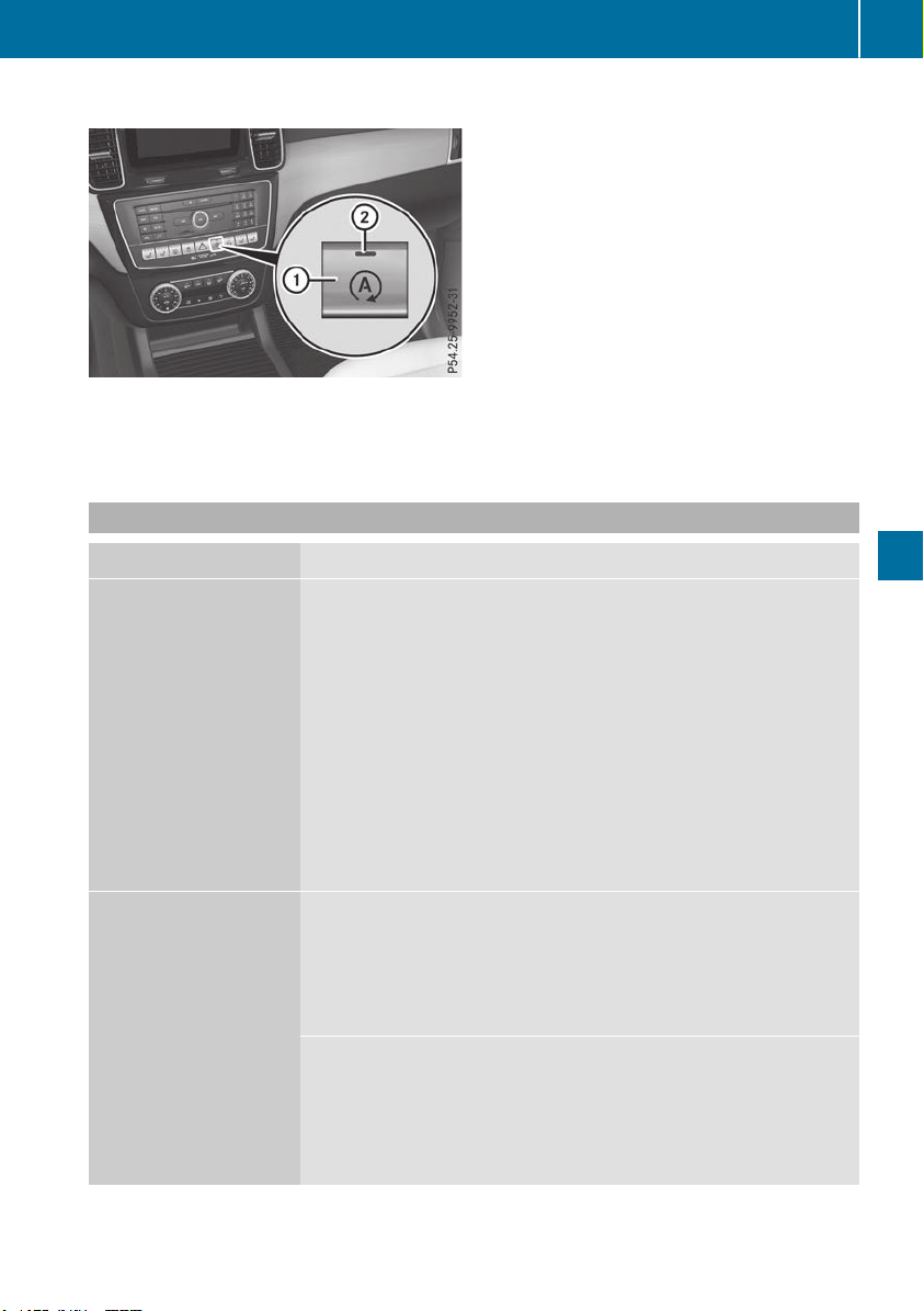
Mercedes-AMG vehicles
X
To deactivate: in the Comfort drive pro-
gram, press ECO button :.
or
X
Activate manual gearshifting (Y page 147).
or
X
Switch to the Sport Plus or Sport drive pro-
gram (Y page 142).
Indicator lamp ; goes out.
X
To activate: press ECO button :.
Indicator lamp ; lights up. When the
Sport Plus or Sport drive program is activa-
ted, the automatic transmission switches to
the Comfort drive program.
If indicator lamp ; is off, the ECO start/stop
function has been deactivated manually or as
the result of a malfunction.
Problems with the engine
Problem
Possible causes/consequences and MM Solutions
The engine does not
start. The starter motor
can be heard.
R
There is a malfunction in the engine electronics.
R
There is a malfunction in the fuel supply.
Before attempting to start the engine again:
X
Turn the SmartKey in the ignition lock back to position u.
or
X
Press the Start/Stop button repeatedly until all indicator lamps in
the instrument cluster go out.
X
Try to start the engine again (Y page 136). Avoid excessively long
and frequent attempts to start the engine as these will drain the
battery.
If the engine does not start after several attempts:
X
Consult a qualified specialist workshop.
The engine does not
start. You cannot hear
the starter motor.
The on-board voltage is too low because the battery is too weak or
discharged.
X
Jump-start the vehicle (Y page 343).
If the engine does not start despite attempts to jump-start it:
X
Consult a qualified specialist workshop.
The starter motor was exposed to a thermal load that was too high.
X
Allow the starter motor to cool down for approximately two minutes.
X
Try to start the engine again.
If the engine still does not start:
X
Consult a qualified specialist workshop.
Driving
141
Driving and parking
Z
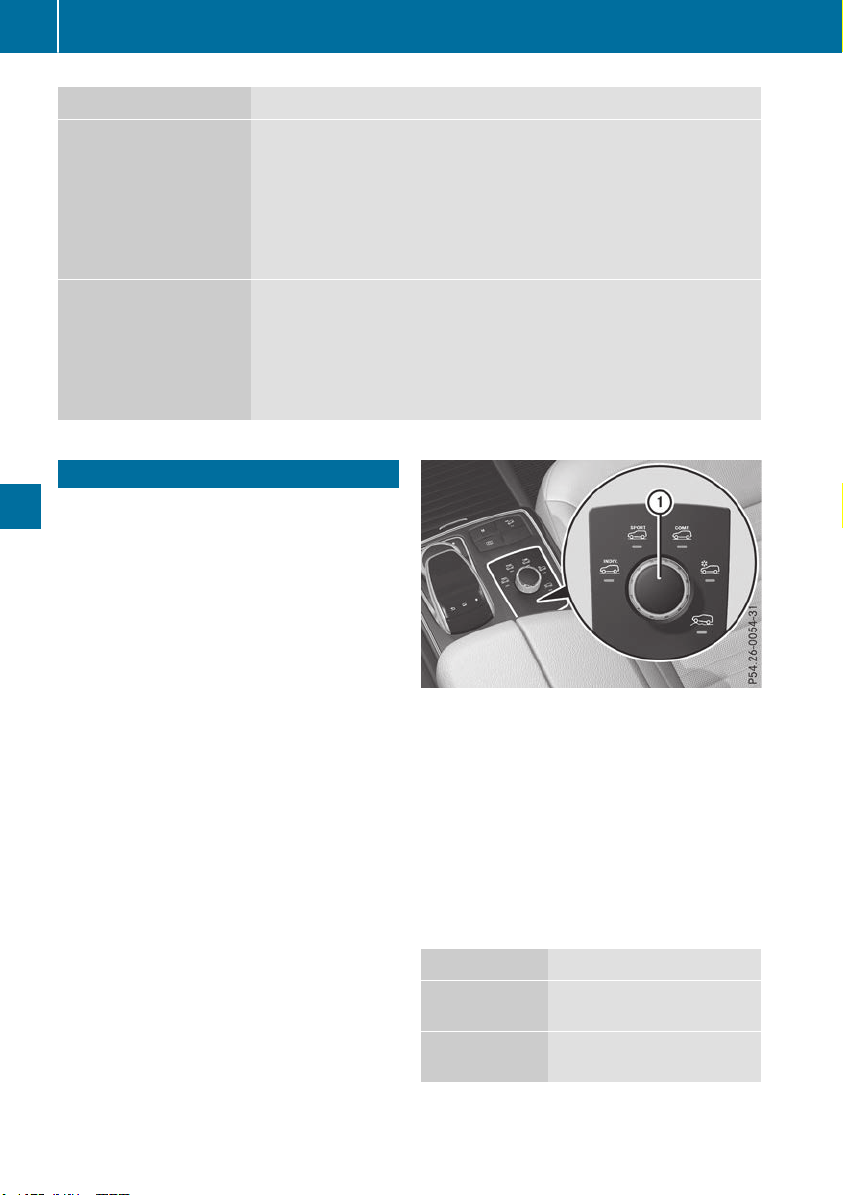
Problem
Possible causes/consequences and MM Solutions
Vehicles with a gasoline
engine:
The engine is not running
smoothly and is misfir-
ing.
There is a malfunction in the engine electronics or in a mechanical
component of the engine management system.
X
Only depress the accelerator pedal slightly.
Otherwise, non-combusted fuel may get into the catalytic converter
and damage it.
X
Have the cause rectified immediately at a qualified specialist work-
shop.
The coolant temperature
gage shows a value
above 248 ‡ (120 †).
The coolant level is too low. The coolant is too hot and the engine is no
longer being cooled sufficiently.
X
Stop as soon as possible and allow the engine and the coolant to
cool down.
X
Check the coolant level (Y page 324). Observe the warning notes
as you do so and add coolant if necessary.
DYNAMIC SELECT controller
Plug-in hybrid: observe the notes on the
DYNAMIC SELECT controller in the separate
operating instructions.
Use the DYNAMIC SELECT controller to change
the drive program. Depending on the drive pro-
gram selected the following vehicle character-
istics will change:
R
the drive (engine and transmission manage-
ment)
R
the transmission
R
the suspension
R
the steering
R
the availability of the ECO start/stop function
Each time you start the engine with the Smart-
Key or the Start/Stop button, the Comfort drive
program is activated. For further information
about starting the engine, see (Y page 136).
The Comfort drive program is recommended in
city traffic and stop/start traffic situations.
X
All vehicles (except Mercedes-AMG vehi-
cles): turn DYNAMIC SELECT controller : as
many times as necessary until the desired
drive program is selected.
The selected drive program appears in the
multifunction display. After five seconds, this
information disappears from the display.
In addition, the current drive program settings
are displayed in the multimedia system dis-
play.
Drive programs available (all vehicles
except Mercedes-AMG vehicles):
Individual
Individual settings
Sport
Sporty driving characteris-
tics
Comfort
Comfortable and economi-
cal driving characteristics
142
DYNAMIC SELECT controller
Driving and parking
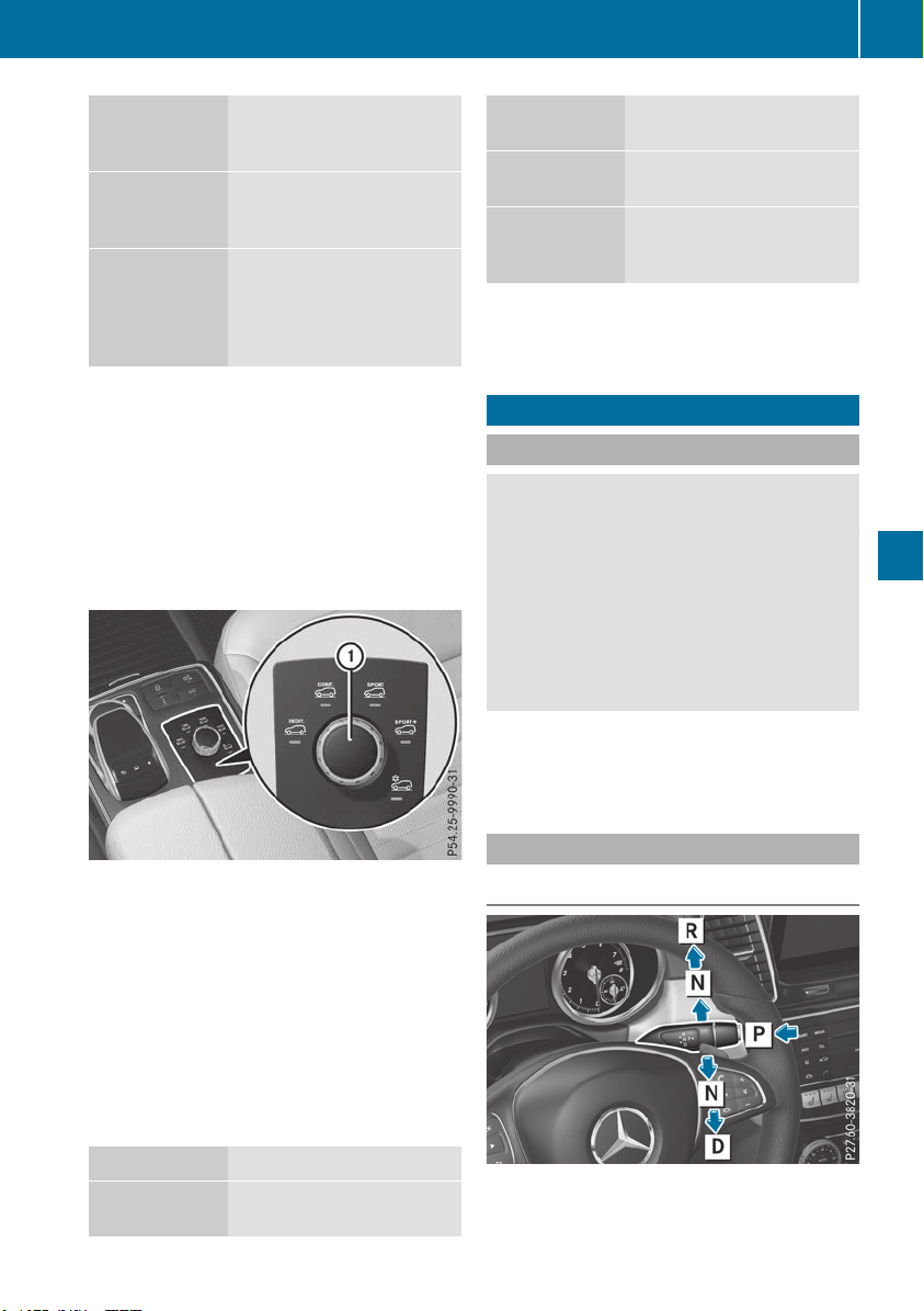
Slippery
Optimal driving characteris-
tics on slippery or snow-
covered roads
Off-road
Optimal driving characteris-
tics for easily negotiable off-
road terrain
Off-road Plus
(vehicles with
Off-road Engi-
neering Pack-
age)
Optimal driving characteris-
tics for rough terrain
Further information on:
R
the Individual, Sport, Comfort and Slippery
drive programs (Y page 146)
R
the Off-road drive program (vehicles without
Off-road Engineering Package)
(Y page 215)
R
the Off-road and Off-road Plus drive pro-
grams (vehicles with Off-road Engineering
Package) (Y page 216)
X
Mercedes-AMG vehicles: turn DYNAMIC
SELECT controller : as many times as nec-
essary until the desired drive program is
selected.
The selected drive program appears in the
multifunction display. After five seconds, this
information disappears from the display.
In addition, the current drive program settings
are displayed in the multimedia system dis-
play.
Drive programs available (Mercedes-AMG
vehicles):
Individual
Individual settings
Comfort
Comfortable and economi-
cal driving characteristics
Sport
Sporty driving characteris-
tics
Sport Plus
Particularly sporty driving
characteristics
Slippery
Optimal driving characteris-
tics on slippery or snow-
covered roads
Additional information for drive programs
(Y page 146).
Automatic transmission
Important safety notes
G
WARNING
The automatic transmission switches to neu-
tral position N when you switch off the engine.
The vehicle may roll away. There is a risk of an
accident.
After switching off the engine, always switch
to parking position P. Prevent the parked vehi-
cle from rolling away by applying the parking
brake.
Plug-in hybrid: be sure to read the separate
Operator's Manual. Otherwise, you may not rec-
ognize dangers.
DIRECT SELECT lever
Overview of transmission positions
j
Park position with parking lock
k
Reverse gear
Automatic transmission
143
Driving and parking
Z

i
Neutral
h
Drive
The DIRECT SELECT lever is on the right of the
steering column.
The DIRECT SELECT lever always returns to its
original position. The current transmission posi-
tion j, k, i or h is shown on the trans-
mission position display on the multifunction
display (Y page 145).
Engaging park position P
!
If the engine speed is too high or the vehicle
is coasting, do not shift the automatic trans-
mission directly from h to k, from k to h
or directly to j. Otherwise, the automatic
transmission may be damaged.
X
Push the DIRECT SELECT lever switch in the
direction of arrow j.
Engaging park position P automatically
Park position j is automatically engaged if:
R
you switch off the engine using the SmartKey
and remove the SmartKey
R
you switch off the engine using the SmartKey
or using the Start/Stop button and open the
driver's door or front-passenger door
R
you open the driver's door when the vehicle is
stationary or when driving at a very low speed
and the transmission is in position h or k
Under certain conditions, the automatic trans-
mission will shift automatically to transmission
position j if the HOLD function or Active Dis-
tance Assist DISTRONIC is activated. Observe
the information on the HOLD function
(Y page 183) and on Active Distance Assist
DISTRONIC (Y page 174).
Engaging reverse gear R
!
Only move the automatic transmission to
k when the vehicle is stationary.
X
If the transmission is in position h or i:
push the DIRECT SELECT lever up past the
first point of resistance.
X
If the transmission is in position j: depress
the brake pedal and push the DIRECT SELECT
lever up past the first point of resistance.
Shifting to neutral N
G
WARNING
If children are left unsupervised in the vehicle,
they could:
R
open the doors, thus endangering other
people or road users.
R
get out and disrupt traffic.
R
operate the vehicle's equipment.
Additionally, children could set the vehicle in
motion if, for example, they:
R
release the parking brake.
R
shifting the automatic transmission out of
park position P
R
Start the engine.
There is a risk of an accident and injury.
When leaving the vehicle, always take the
SmartKey with you and lock the vehicle. Never
leave children or animals unattended in the
vehicle. Always keep the SmartKey out of
reach of children.
X
If the transmission is in position h or k:
push the DIRECT SELECT lever up or down to
the first point of resistance.
X
If the transmission is in position j: depress
the brake pedal and push the DIRECT SELECT
lever up or down to the first point of resist-
ance.
If you switch the engine off with the transmis-
sion in position k or h, the automatic trans-
mission shifts to i automatically.
With the SmartKey: if you then open the driv-
er's door or the front-passenger door or remove
the SmartKey from the ignition lock, the auto-
matic transmission shifts to j automatically.
With the Start/Stop button: if you then open
the driver's door or the front-passenger door,
the automatic transmission shifts automatically
to j.
If you want the automatic transmission to
remain in neutral i, e.g. when having the vehi-
cle cleaned in an automatic, tow-through car
wash:
144
Automatic transmission
Driving and parking

With the SmartKey:
X
Switch on the ignition.
X
Depress the brake pedal and keep it
depressed.
X
Shift to neutral i.
X
Release the brake pedal.
X
Release the electric parking brake.
X
Switch off the ignition and leave the SmartKey
in the ignition lock.
With the Start/Stop button:
X
Remove the Start/Stop button from the igni-
tion lock.
X
Insert the SmartKey into the ignition lock.
X
Switch on the ignition.
X
Depress the brake pedal and keep it
depressed.
X
Shift to neutral i.
X
Release the brake pedal.
X
Release the electric parking brake.
X
Switch off the ignition and leave the SmartKey
in the ignition lock.
Engaging drive position D
X
If the transmission is in position k or i:
push the DIRECT SELECT lever down past the
first point of resistance.
X
If the transmission is in position j: depress
the brake pedal and push the DIRECT SELECT
lever down past the first point of resistance.
Transmission position and drive pro-
gram display
The current transmission position and drive pro-
gram appear in the multifunction display.
:
Transmission position
;
Gear
=
Drive program
The arrows in the transmission position display
show how and into which transmission positions
you can shift using the DIRECT SELECT lever.
If the transmission position display on the mul-
tifunction display is not working, you should pull
away carefully to check whether the desired
transmission position is engaged. Ideally, you
should select transmission position h.
Transmission positions
B
Park position
Only shift the transmission into posi-
tion j (Y page 156) when the vehi-
cle is stationary. The parking lock
should not be used as a brake when
parking. Always apply the electronic
parking brake in addition to the park-
ing lock in order to secure the vehi-
cle.
In the event of a malfunction of the
vehicle's electronics, the transmis-
sion may lock in position j. Have
the vehicle electronics checked
immediately at a qualified specialist
workshop.
Park position j is automatically
engaged if:
R
you switch off the engine using the
SmartKey and remove the Smart-
Key
R
you switch off the engine using the
SmartKey or using the Start/Stop
button and open the driver's door
or front-passenger door
R
you open the driver's door when
the vehicle is stationary or when
driving at a very low speed and the
transmission is in position h or
k
C
Reverse gear
Shift the transmission into position
k only when the vehicle is station-
ary.
Automatic transmission
145
Driving and parking
Z

A
Neutral
Do not shift the transmission to i
while driving. The automatic trans-
mission could otherwise be dam-
aged.
No power is transmitted from the
engine to the drive wheels.
Releasing the brakes will allow you to
move the vehicle freely, e.g. to push
it or tow it.
If ESP
®
is deactivated or faulty: shift
the transmission to position i if the
vehicle is in danger of skidding, e.g.
on icy roads.
If you switch the engine off with the
transmission in position k or h,
the automatic transmission will shift
to i automatically.
!
Coasting in neutral i may
cause damage to the drive train.
7
Drive
The automatic transmission changes
gear automatically. All forward gears
are available.
Driving tips
Changing gear
The automatic transmission shifts through the
individual gears automatically when it is in trans-
mission position h. This automatic gear shift-
ing behavior is determined by:
R
the selected drive program
R
the position of the accelerator pedal
R
the road speed
Accelerator pedal position
Your style of driving influences how the auto-
matic transmission shifts gear:
R
little throttle: early upshifts
R
more throttle: late upshifts
Kickdown
Use kickdown for maximum acceleration.
X
Depress the accelerator pedal beyond the
pressure point.
The automatic transmission shifts to a lower
gear depending on the engine speed.
X
Ease off the accelerator pedal once the
desired speed is reached.
The automatic transmission shifts back up.
Rocking the vehicle free
Shifting back and forth between transmission
positions h and k can help to free up the
vehicle if it gets stuck in mud or snow. The vehi-
cle's engine management system limits the
speed to a maximum of 5 mph (9 km/h) when
shifting back and forth. To shift repeatedly
between transmission positions h and k,
move the DIRECT SELECT lever up and down
beyond the pressure point.
Towing a trailer
X
Drive in the middle of the engine speed range
on uphill gradients.
X
Depending on the uphill or downhill gradient,
use the left-hand steering wheel paddle
shifter (Y page 147) to select a lower gear,
even if cruise control or Active Distance
Assist DISTRONIC is activated.
Drive programs
Slippery drive program
The Slippery drive program has the following
characteristics:
R
reduced engine and transmission settings for
optimum propulsion on slippery or snow-cov-
ered roads.
R
optimized ESP
®
stability control on slippery or
snow-covered roads.
R
the vehicle has improved driving stability on
slippery or snow-covered roads, for example.
146
Automatic transmission
Driving and parking

Comfort drive program
The Comfort drive program has the following
characteristics:
R
comfort-oriented engine and transmission
settings.
R
optimal fuel consumption resulting from the
automatic transmission shifting up sooner.
R
the vehicle pulls away more gently in forward
and reverse gears, unless the accelerator
pedal is depressed fully.
R
the automatic transmission shifting up
sooner. This results in the vehicle being driven
at lower engine speeds and the wheels being
less likely to spin.
Sport drive program
The Sport drive program has the following char-
acteristics:
R
sporty engine and transmission settings.
R
the automatic transmission shifts up later.
The fuel consumption possibly being higher
as a result of the later automatic transmission
shift points.
R
the suspension exhibits sporty damping (vehi-
cles with AIRMATIC).
Drive program Sport Plus (Mercedes-
AMG vehicles)
The Sport Plus drive program has the following
characteristics:
R
the vehicle exhibits particularly sporty driving
characteristics.
R
the vehicle pulls away in first gear.
R
the automatic transmission shifts up later.
The fuel consumption possibly being higher
as a result of the later automatic transmission
shift points.
R
the suspension exhibits particularly firm
springing and damping settings (vehicles with
AIRMATIC).
R
the ECO start/stop function is deactivated, it
can, however, be activated again using the
ECO button (Y page 140).
Individual drive program
In the Individual drive program, the following
properties of the drive program can be selected:
R
the drive (engine and transmission manage-
ment)
R
the transmission
R
the suspension (vehicles with AIRMATIC)
R
all vehicles (except Mercedes-AMG vehicles):
the steering
To select the gears in the Individual drive pro-
gram permanently using the steering wheel pad-
dle shifters, select the permanent manual gear-
shift program.
Information about configuring the Individual
drive program with the multimedia system can
be found in the Digital Operator's Manual.
Manual gear shifting
General notes
You can change gear yourself using the steering
wheel paddle shifters. The transmission must be
in position h to do this.
Depending on which steering wheel paddle
shifter is pulled, the automatic transmission
immediately shifts into the next gear down or
up, if permitted.
To use manual shifting, you have two options:
R
temporary setting
R
permanent setting
If you activate manual gearshifting, the current
gear appears in the multifunction display
instead of transmission position h.
If manual gearshifting is deactivated, the gears
will be selected automatically.
Automatic transmission
147
Driving and parking
Z
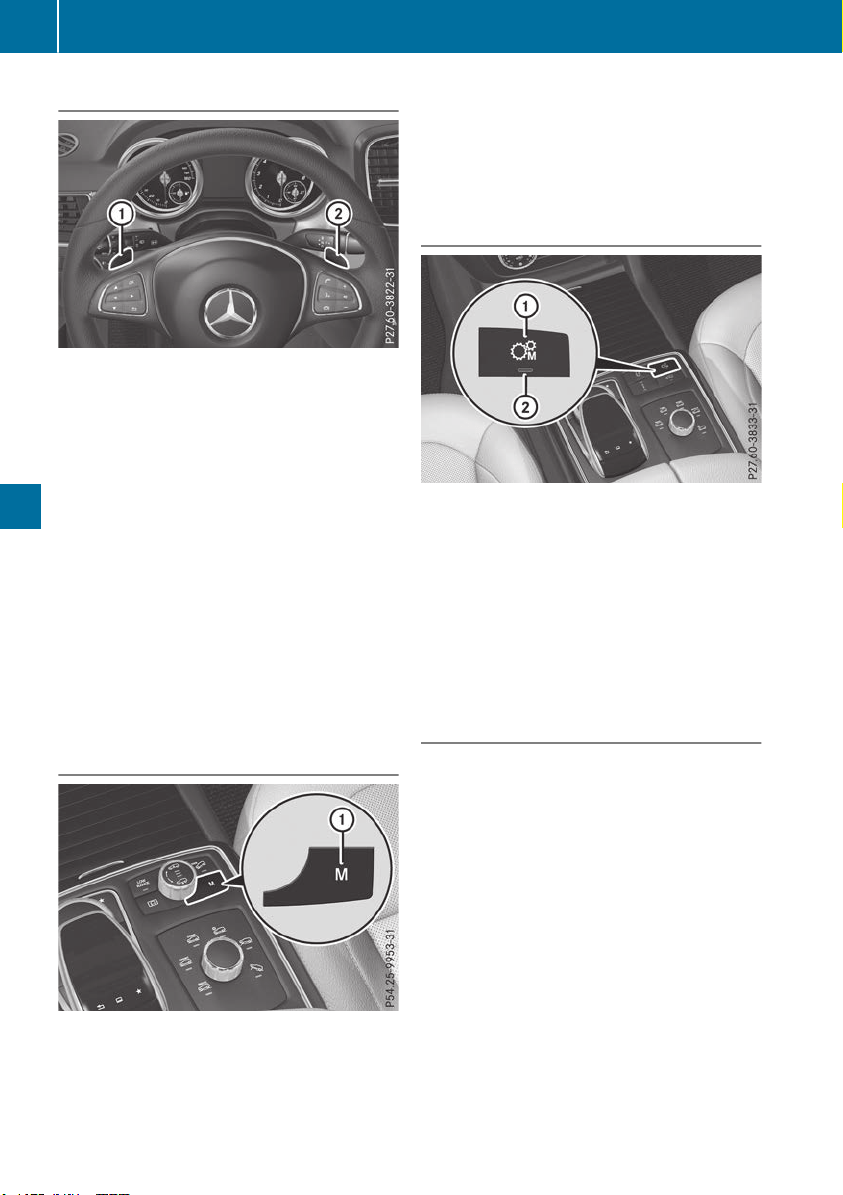
Temporary setting
X
To activate: shift the DIRECT SELECT lever to
position h.
X
Pull steering wheel paddle shifter : or ;.
The temporary setting is active for a certain
amount of time. Under certain conditions, the
minimum amount of time is extended, e.g. in the
case of lateral acceleration, during overrun
mode or when driving on steep terrain.
X
To deactivate: pull steering wheel paddle
shifter ; and hold it in place.
or
X
Use the DIRECT SELECT lever to switch the
transmission position.
or
X
Use the DYNAMIC SELECT controller to
change the drive program.
Permanent setting (all vehicles except
Mercedes-AMG vehicles)
X
To activate: shift the DIRECT SELECT lever to
position h.
X
Press button :.
X
To deactivate: press button :.
or
X
Use the DYNAMIC SELECT controller to
change the drive program.
Permanent setting (Mercedes-AMG
vehicles)
X
To activate: shift the DIRECT SELECT lever to
position h.
X
Press button :.
Indicator lamp ; lights up.
X
To deactivate: press button :.
or
X
Use the DYNAMIC SELECT controller to
switch to the Individual drive program.
Indicator lamp ; goes out.
Shifting gears
!
Mercedes-AMG vehicles: the automatic
transmission does not shift up automatically
even when the engine limiting speed for the
current gear is reached. When the engine lim-
iting speed is reached, the fuel supply is cut to
prevent the engine from overrevving. Always
make sure that the engine speed does not
reach the red area of the tachometer. There is
otherwise a risk of engine damage.
148
Automatic transmission
Driving and parking
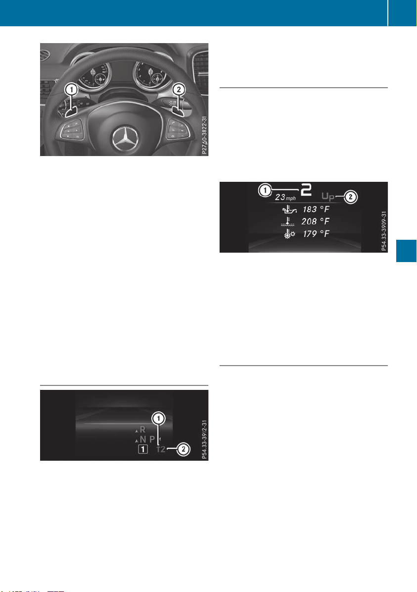
X
To shift up: pull steering wheel paddle
shifter ;.
The automatic transmission shifts up to the
next gear.
All vehicles (except Mercedes-AMG vehi-
cles): if the maximum engine speed in the
gear currently engaged is reached and you
continue to accelerate, the automatic trans-
mission automatically shifts up to prevent
engine damage.
X
To shift down: pull steering wheel paddle
shifter :.
The automatic transmission shifts down to
the next gear.
Automatic down shifting occurs when coast-
ing.
If the engine were to exceed the maximum
engine speed when shifting down, the auto-
matic transmission protects against engine
damage by not shifting down.
Shift recommendation
The gearshift recommendations assist you in
adopting an economical driving style. The rec-
ommended gear is shown in the multifunction
display.
X
When the corresponding gearshift recom-
mendation : appears in the multifunction
display of the instrument cluster, shift to rec-
ommended gear ;.
Upshifting (Mercedes-AMG vehicles)
!
In manual mode, the automatic transmis-
sion does not shift up automatically even
when the engine limiting speed for the current
gear is reached. When the engine limiting
speed is reached, the fuel supply is cut to
prevent the engine from overrevving. Always
make sure that the engine speed does not
reach the red area of the tachometer. There is
otherwise a risk of engine damage.
:
Gear indicator
;
Upshift indicator
Before the engine speed reaches the red area,
an upshift indicator will be shown in the multi-
function display.
X
When the UPUP message appears in the multi-
function display, pull on the right-hand steer-
ing wheel paddle shifter.
Kickdown
Mercedes-AMG vehicles: kickdown is only
possible in the temporary setting.
X
For maximum acceleration, depress the
accelerator pedal beyond the pressure point.
The automatic transmission shifts to a lower
gear depending on the engine speed.
X
Shift back up once the desired speed is
reached.
During kickdown, you cannot shift gears using
the steering wheel paddle shifters.
If you apply full throttle, the automatic trans-
mission shifts up to the next gear when the
maximum engine speed is reached. This pre-
vents the engine from overrevving.
Automatic transmission
149
Driving and parking
Z

Problems with the transmission
Problem
Possible causes/consequences and MM Solutions
The transmission has
problems shifting gear.
The transmission is losing oil.
X
Have the transmission checked at a qualified specialist workshop
immediately.
7G-TRONIC:
The acceleration ability
is deteriorating.
The transmission no lon-
ger changes gear.
The transmission is in emergency mode.
It is only possible to shift into second gear and reverse gear.
X
Stop the vehicle.
X
Shift the transmission to position j.
X
Switch off the engine.
X
Wait at least ten seconds before restarting the engine.
X
Shift the transmission to position h or k.
If h is selected, the transmission shifts to second gear; if k is
selected, the transmission shifts to reverse gear.
X
Have the transmission checked at a qualified specialist workshop
immediately.
9G-TRONIC:
The acceleration ability
is deteriorating.
The transmission no lon-
ger changes gear.
The transmission is in emergency mode.
It is only partly possible to engage the gears, or the transmission is in
position i.
X
Stop the vehicle.
X
Shift the transmission to position j.
X
Switch off the engine.
X
Wait at least ten seconds before restarting the engine.
X
Shift the transmission to position h or k.
X
Have the transmission checked at a qualified specialist workshop
immediately.
Transfer case
This section is only valid for vehicles with 4-
wheel drive (4MATIC). Power is always trans-
mitted to both axles.
!
Performance tests may only be carried out
on a 2-axle dynamometer. The brake system
or transfer case could otherwise be damaged.
Contact a qualified specialist workshop for a
performance test.
!
Because ESP
®
is an automatic system, the
engine and ignition must be switched off
(SmartKey in position 0 or 1 or Start/Stop
button in position 0 or 1) when the electric
parking brake is being tested on a brake dyna-
mometer (maximum 10 seconds).
Braking triggered automatically by ESP
®
may
seriously damage the brake system.
!
Vehicles with 4MATIC must not be towed
with either the front or the rear axle raised, as
doing so will damage the transmission.
Refueling
Important safety notes
G
WARNING
Fuel is highly flammable. Risk of fire and
explosion by improper handling of fuel.
You must avoid fire, open flames, smoking
and creating sparks. Switch off the ignition
before refueling and, if present, switch off the
auxiliary heating.
150
Refueling
Driving and parking

G
WARNING
Fuel is poisonous and hazardous to health.
There is a risk of injury.
You must make sure that fuel does not come
into contact with your skin, eyes or clothing
and that it is not swallowed. Do not inhale fuel
vapors. Keep fuel away from children.
If you or others come into contact with fuel,
observe the following:
R
Wash away fuel from skin immediately
using soap and water.
R
If fuel comes into contact with your eyes,
immediately rinse them thoroughly with
clean water. Seek medical assistance with-
out delay.
R
If fuel is swallowed, seek medical assis-
tance without delay. Do not induce vomit-
ing.
R
Immediately change out of clothing which
has come into contact with fuel.
G
WARNING
Electrostatic charge can cause sparks and
thereby ignite fuel vapors. There is a risk of
fire and explosion.
Before you open the fuel filler cap or take hold
of the pump nozzle, touch the metallic vehicle
body. This discharges any electrostatic
charge that may have built up.
Do not get into the vehicle again during the
refueling process. Otherwise, electrostatic
charge could build up again.
G
WARNING
Vehicles with a diesel engine:
If you mix diesel fuel with gasoline, the flash
point is lower than that of pure diesel fuel.
When the engine is running, exhaust system
components could overheat without being
noticed. There is a risk of fire.
Never refuel with gasoline. Never mix gasoline
with diesel fuel.
!
Do not use gasoline to refuel vehicles with a
diesel engine. Do not switch on the ignition if
you accidentally refuel with the wrong fuel.
Otherwise, the fuel will enter the fuel system.
Even small amounts of the wrong fuel could
result in damage to the fuel system and the
engine. The repair costs are high. Notify a
qualified specialist workshop and have the
fuel tank and fuel lines drained completely.
!
Do not use diesel to refuel vehicles with a
gasoline engine. Do not switch on the ignition
if you accidentally refuel with the wrong fuel.
Otherwise, the fuel will enter the fuel system.
Even small amounts of the wrong fuel could
result in damage to the fuel system and the
engine. Notify a qualified specialist workshop
and have the fuel tank and fuel lines drained
completely.
!
Overfilling the fuel tank could damage the
fuel system.
!
Take care not to spill any fuel on painted
surfaces. You could otherwise damage the
paintwork.
!
Use a filter when adding fuel from a fuel can.
The fuel lines and/or the fuel injection system
could otherwise be blocked by particles from
the fuel can.
Do not get into the vehicle again during the refu-
eling process. Otherwise, electrostatic charge
could build up again.
If you overfill the fuel tank, fuel could spray out
when the fuel pump nozzle is removed.
i
Flexible Fuel vehicles can be recognized by
the Ethanol up to E85 sticker on the inside of
the fuel filler flap. Please note that the warn-
ings about the risk of fire, explosion or injury
also refer to Flexible Fuel vehicles.
For further information on fuel and fuel quality
(Y page 384).
Refueling
General information
Pay attention to the important safety notes
(Y page 150).
If you unlock/lock the vehicle from the outside,
the fuel filler flap also unlocks/locks.
The position of the fuel filler cap is displayed in
the instrument cluster 8. The arrow next to
the filling pump indicates the side of the vehicle.
Refueling
151
Driving and parking
Z
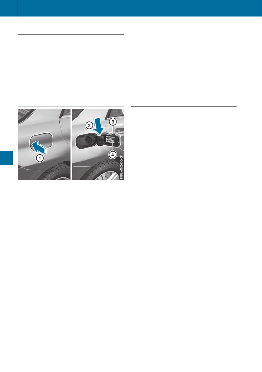
Preparing to refuel
X
Switch off the engine.
X
Remove the SmartKey from the ignition lock.
or, on vehicles with KEYLESS‑GO:
X
Open the driver's door.
The vehicle electronics now have status g.
This is the same as the SmartKey having been
removed.
The driver’s door can be closed again.
Opening the fuel filler flap
:
Opens the fuel filler flap
;
Insert the fuel filler cap
=
Instruction label for fuel type to be refueled
?
Tire pressure table
X
Press the fuel filler flap in the direction of
arrow :.
The fuel filler flap swings up.
X
Turn the fuel filler cap counterclockwise and
remove it.
X
Insert the fuel filler cap into the holder
bracket on the inside of the filler flap in the
direction of arrow ;.
X
Completely insert the filler neck of the fuel
pump nozzle into the tank, hook in place and
refuel.
X
Only fill the tank until the pump nozzle
switches off.
Do not add any more fuel after the pump stops
filling for the first time. Otherwise, fuel may
leak out.
Vehicles with a diesel engine: the filler neck is
designed for refueling at diesel filling pumps.
Closing the fuel filler flap
X
Replace the cap on the filler neck and turn
clockwise until it engages audibly.
X
Close the fuel filler flap.
Close the fuel filler flap before locking the vehi-
cle.
If you drive at speeds above 1 mph (2 km/h)
with the fuel filler flap open, the Fuel FillerFuel Filler
Flap OpenFlap Open message is shown in the multifunc-
tion display.
If you are driving with the fuel filler cap open, the
8 reserve fuel warning lamp flashes. A mes-
sage appears in the multifunction display
(Y page 259).
In addition, the ; Check Engine warning
lamp may light up (Y page 283).
i
For further information on warning and indi-
cator lamps in the instrument cluster, see
(Y page 283).
152
Refueling
Driving and parking

Problems with fuel and the fuel tank
Problem
Possible causes/consequences and MM Solutions
Fuel is leaking from the
vehicle.
G
WARNING
The fuel line or the fuel tank is faulty.
Risk of explosion or fire.
X
Apply the electric parking brake.
X
Switch off the engine.
X
Remove the SmartKey from the ignition lock.
or, in vehicles with KEYLESS-GO start-function or KEYLESS‑GO
X
Open the driver's door.
The vehicle electronics are now in key position u. This is the same
as the SmartKey having been removed.
X
Do not restart the engine under any circumstances.
X
Consult a qualified specialist workshop.
The engine does not
start.
The fuel tank of a vehicle with a diesel engine has been run completely
dry.
X
Refuel the vehicle with at least 5.3 US qt (5 liters) of diesel.
X
Turn the ignition on for approximately ten seconds (Y page 135).
X
Start the engine continuously for up to ten seconds until it runs
smoothly.
If the engine does not start:
X
Turn the ignition on again for approximately ten seconds
(Y page 135).
X
Start the engine again continuously for up to ten seconds until it
runs smoothly.
If the engine does not start after three attempts:
X
Consult a qualified specialist workshop.
The fuel filler flap cannot
be opened.
The fuel filler flap is not unlocked.
X
Unlock the vehicle (Y page 77).
The SmartKey battery is discharged or nearly discharged.
X
Unlock the vehicle using the mechanical key (Y page 79).
The fuel filler flap is unlocked, but the opening mechanism is jammed.
X
Consult a qualified specialist workshop.
DEF (BlueTEC vehicles only)
General notes
To function properly, BlueTEC exhaust gas after-
treatment must be operated with the reducing
agent DEF. Adding DEF is one of the tasks per-
formed during maintenance.
When the supply of DEF is almost used up, the
Check Additive See Operator's ManualCheck Additive See Operator's Manual
message is shown in the multifunction display.
If you drive the vehicle faster than 10 mph
(16 km/h), the Check Additive See Opera‐Check Additive See Opera‐
tor's Manualtor's Manual message goes out after approx-
imately one minute.
Refueling
153
Driving and parking
Z

When the DEF supply drops to a minimum, the
Remaining Starts: 16Remaining Starts: 16 message is shown in
the multifunction display.
If the Remaining Starts: 16Remaining Starts: 16 message
appears in the multifunction display, you can
start the engine another 16 times. If DEF is not
refilled, you will subsequently be unable to
start the engine.
X
Add at least 2 gal (7.5 l) of DEF.
X
Switch on the ignition for at least 60 seconds.
X
Start the engine.
i
The DEF range shown depends strongly on
the driving style and operating conditions.
The actual range can therefore deviate from
the calculated range. The DEF consumption is
between 1% and 5% of the fuel consumption.
i
Have the DEF tank refilled at a qualified spe-
cialist workshop.
Use the special DEF refill bottle when adding
DEF between maintenance intervals. You can
obtain further information from an authorized
Mercedes-Benz Center or, if necessary, contact
Roadside Assistance (Y page 29).
If the outside temperature is below 12 ‡
(Ò11 †), it may be difficult to top up. If DEF is
frozen and there is an active warning indicator, it
may not be possible to add DEF. Park the vehicle
in a warmer place, e.g. in a garage, until DEF has
become fluid again. It will then be possible to
add DEF again. Alternatively, have the DEF tank
refilled at a qualified specialist workshop.
Further information about BlueTEC exhaust gas
aftertreatment and DEF is available at any
authorized Mercedes-Benz Center.
Important safety notes
DEF is a water-soluble fluid for the exhaust gas
aftertreatment of diesel engines. It is:
R
Not poisonous
R
Colorless and odorless
R
Not flammable
When you open the DEF container, small
amounts of ammonia vapor may be released.
Ammonia vapors have a pungent odor and are
particularly irritating to the skin, to mucous
membranes and to the eyes. You may experi-
ence a burning sensation in your eyes, nose and
throat. Coughing and watering of the eyes are
possible.
Do not inhale ammonia vapors. Fill the DEF tank
only in well-ventilated areas.
DEF must not come into contact with your skin,
eyes or clothing and must not be swallowed.
Keep DEF away from children.
If you or other persons come into contact with
DEF, observe the following:
R
Rinse DEF from your skin immediately with
soap and water.
R
If DEF comes into contact with your eyes,
immediately rinse them thoroughly with clean
water. Seek medical assistance without
delay.
R
If DEF has been swallowed, rinse your mouth
out immediately. Drink plenty of water. Seek
medical assistance without delay.
R
Change out of clothing contaminated with
DEF immediately.
!
Only use DEF in accordance with
ISO 22241. Do not mix any additives with
DEF, and do not dilute DEF with water. This
may destroy the BlueTEC exhaust gas after-
treatment system.
!
The vehicle must be parked on level ground
to fill the DEF tank. The DEF tank can only be
filled as intended with the vehicle parked on a
level surface. This avoids false level readings.
Filling the tank is not permitted if the vehicle
is not parked on a level surface. There is a
danger of overfilling, which could result in
damage to components of the BlueTEC
exhaust gas aftertreatment.
!
Immediately rinse off surfaces which come
into contact with DEF or remove DEF with a
damp cloth and cold water. If DEF has already
crystallized, clean using a sponge and cold
water. DEF residue crystallizes after a short
period and contaminates the affected surfa-
ces. Furthermore, electrical components in
the vicinity may be damaged by DEF.
!
DEF is not a fuel additive and must not be
added to the fuel tank. If DEF is added to the
fuel tank, this can lead to engine damage.
For further information on DEF, see
(Y page 386).
154
Refueling
Driving and parking

Opening/closing the DEF filler cap
The fuel filler flap is unlocked or locked auto-
matically when you open or close the vehicle
with the SmartKey or with KEYLESS-GO.
X
To open: switch the ignition off.
X
Press the fuel filler flap in the direction of
arrow :.
The fuel filler flap swings up.
X
Turn blue DEF fuel filler cap ; counter-clock-
wise and remove it.
DEF filler cap ; is secured with a plastic
strip.
X
To close: place DEF filler cap ; on the filler
neck and turn it clockwise.
X
To close the fuel filler flap, press it in the
direction of arrow :.
X
Drive faster than 10 mph (16 km/h).
The Check Additive See Operator'sCheck Additive See Operator's
ManualManual message disappears after approx-
imately one minute.
i
If the Check Additive See Operator'sCheck Additive See Operator's
ManualManual message continues to be shown on
the multifunction display, you must add more
DEF.
DEF refill canisters
!
Do not screw the disposable hose on too
tight. The disposable hose could otherwise be
damaged and DEF may leak out.
X
Unscrew the cap from the opening on top of
DEF refill canister ;.
X
Place disposable hose : on the opening of
DEF refill canister ; and screw it on clock-
wise until hand-tight.
Disposable hose : remains closed until you
fasten disposable hose : to the DEF filler
neck of the vehicle.
X
Place disposable hose : on the filler neck on
the vehicle and screw it on clockwise until
hand-tight. When you feel resistance, dispos-
able hose : is sufficiently secured.
X
Lift up and tip DEF refill canister ;.
Filling stops when the DEF tank is completely
filled. Do not fill the DEF tank any further. DEF
refill canister ; can be removed when it has
been only partially emptied.
X
Turn disposable hose : on the filler neck of
the vehicle counter-clockwise and remove it.
X
Turn disposable hose : on the opening of
DEF refill canister ; counter-clockwise and
remove it.
X
Reseal DEF refill canister ; with the cap.
DEF refill canisters are available at many gas
stations or at a qualified specialist workshop.
DEF refill canisters are often sold with a filler
hose. A filler hose that does not exactly fill the
vehicle's DEF tank offers no protection against
Refueling
155
Driving and parking
Z
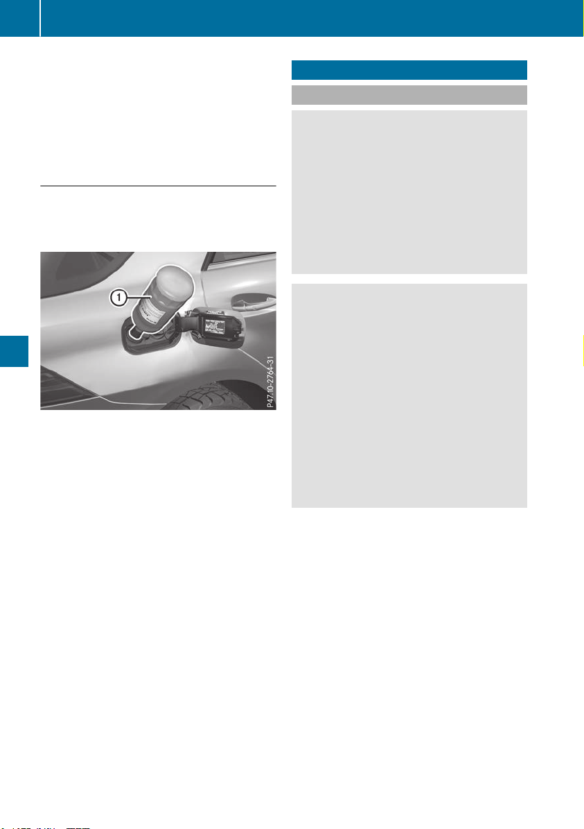
overfilling. DEF may leak if overfilled. Mercedes-
Benz offers a special disposable hose with over-
fill protection. You can obtain this from any
authorized Mercedes-Benz Center. DEF is avail-
able in a variety of containers and receptacles.
Only use the disposable hose with the
Mercedes-Benz DEF refill canisters.
DEF refill bottle
!
Only screw on the DEF refill bottle hand-
tight. Otherwise, the thread of the DEF refill
bottle could be damaged and DEF could leak
out.
X
Unscrew the protective cap from DEF refill
bottle :.
X
Place DEF refill bottle : on the filler neck as
shown and screw it on clockwise until hand-
tight.
X
Press DEF refill bottle : towards the filler
neck.
The DEF tank is filled. This may take up to one
minute.
i
When DEF refill bottle : is no longer
pressed, filling stops and the bottle may be
taken off again after being only partially emp-
tied.
X
Release DEF refill bottle :.
X
Turn DEF refill bottle : counter-clockwise
and remove it.
X
Screw the protective cap onto DEF refill bot-
tle : again.
DEF refill bottles are available at many gas sta-
tions or at a qualified specialist workshop. Refill
bottles without a threaded cap do not provide
overfill protection. DEF may leak if overfilled.
Mercedes Benz offers special refill bottles with a
threaded seal. These are available at any author-
ized Mercedes-Benz Center.
Parking
Important safety notes
G
WARNING
Flammable material such as leaves, grass or
twigs may ignite if they come into contact with
hot parts of the exhaust system or exhaust
gas flow. There is a risk of fire.
Park the vehicle so that no flammable mate-
rials come into contact with parts of the vehi-
cle which are hot. Take particular care not to
park on dry grassland or harvested grain
fields.
G
WARNING
If you leave children unsupervised in the vehi-
cle, they could set it in motion by, for example:
R
release the parking brake.
R
shift the automatic transmission out of the
parking position P.
R
start the engine.
In addition, they may operate vehicle equip-
ment and become trapped. There is a risk of
an accident and injury.
When leaving the vehicle, always take the
SmartKey with you and lock the vehicle. Never
leave children unsupervised in the vehicle.
!
Always secure the vehicle correctly against
rolling away. Otherwise, the vehicle or its driv-
etrain could be damaged.
To ensure that the vehicle is secured against
rolling away unintentionally:
R
the electric parking brake must be applied
R
the transmission must be in position j and
the SmartKey must be removed from the igni-
tion lock
R
the front wheels must be turned towards the
curb on steep uphill or downhill gradients
R
the empty vehicle must be secured at the
front axle with a wheel chock or similar, for
example, on uphill or downhill gradients
R
a laden vehicle must also be secured at the
rear axle with a wheel chock or similar, for
example, on uphill or downhill gradients
156
Parking
Driving and parking

Switching off the engine
G
WARNING
The automatic transmission switches to neu-
tral position N when you switch off the engine.
The vehicle may roll away. There is a risk of an
accident.
After switching off the engine, always switch
to parking position P. Prevent the parked vehi-
cle from rolling away by applying the parking
brake.
X
Apply the electric parking brake.
X
Shift the transmission to position j.
X
With the SmartKey: turn the SmartKey to
position u in the ignition lock and remove it.
The immobilizer is activated.
X
With KEYLESS-GO:
Press the Start/Stop button (Y page 135)
The engine stops and all the indicator lamps in
the instrument cluster go out.
If you switch the engine off with the transmis-
sion in position k or h, the automatic trans-
mission shifts to i automatically.
If you then open the driver's or front-passenger
door, the automatic transmission shifts to j
automatically.
If you want the automatic transmission to
remain in neutral i, e.g. when having the vehi-
cle cleaned in an automatic, tow-through car
wash:
X
Vehicles with a SmartKey: switch on the
ignition.
X
Vehicles with KEYLESS-GO: remove the
Start/Stop button from the ignition lock.
X
Insert the SmartKey into the ignition lock.
X
Switch on the ignition.
X
All vehicles: depress the brake pedal and
keep it depressed.
X
Engage neutral i.
X
Release the brake pedal.
X
Release the electric parking brake.
X
Switch off the ignition and leave the SmartKey
in the ignition lock.
i
The engine can be switched off in an emer-
gency while the vehicle is in motion by press-
ing and holding the Start/Stop button for
three seconds.
Electric parking brake
General notes
G
WARNING
If you leave children unsupervised in the vehi-
cle, they could set it in motion by, for example:
R
release the parking brake.
R
shift the automatic transmission out of the
parking position P.
R
start the engine.
In addition, they may operate vehicle equip-
ment and become trapped. There is a risk of
an accident and injury.
When leaving the vehicle, always take the
SmartKey with you and lock the vehicle. Never
leave children unsupervised in the vehicle.
The function of the electric parking brake is
dependent on the on-board voltage. If the on-
board voltage is low or there is a malfunction in
the system, it may not be possible to apply the
released parking brake.
X
If this is the case, only park the vehicle on
level ground and secure it to prevent it rolling
away.
X
Shift the automatic transmission to position
j.
It may not be possible to release an applied
parking brake if the on-board voltage is low or
there is a malfunction in the system. Contact a
qualified specialist workshop.
i
The electric parking brake performs a func-
tion test at regular intervals while the engine
is switched off. The sounds that can be heard
while this is occurring are normal.
Parking
157
Driving and parking
Z
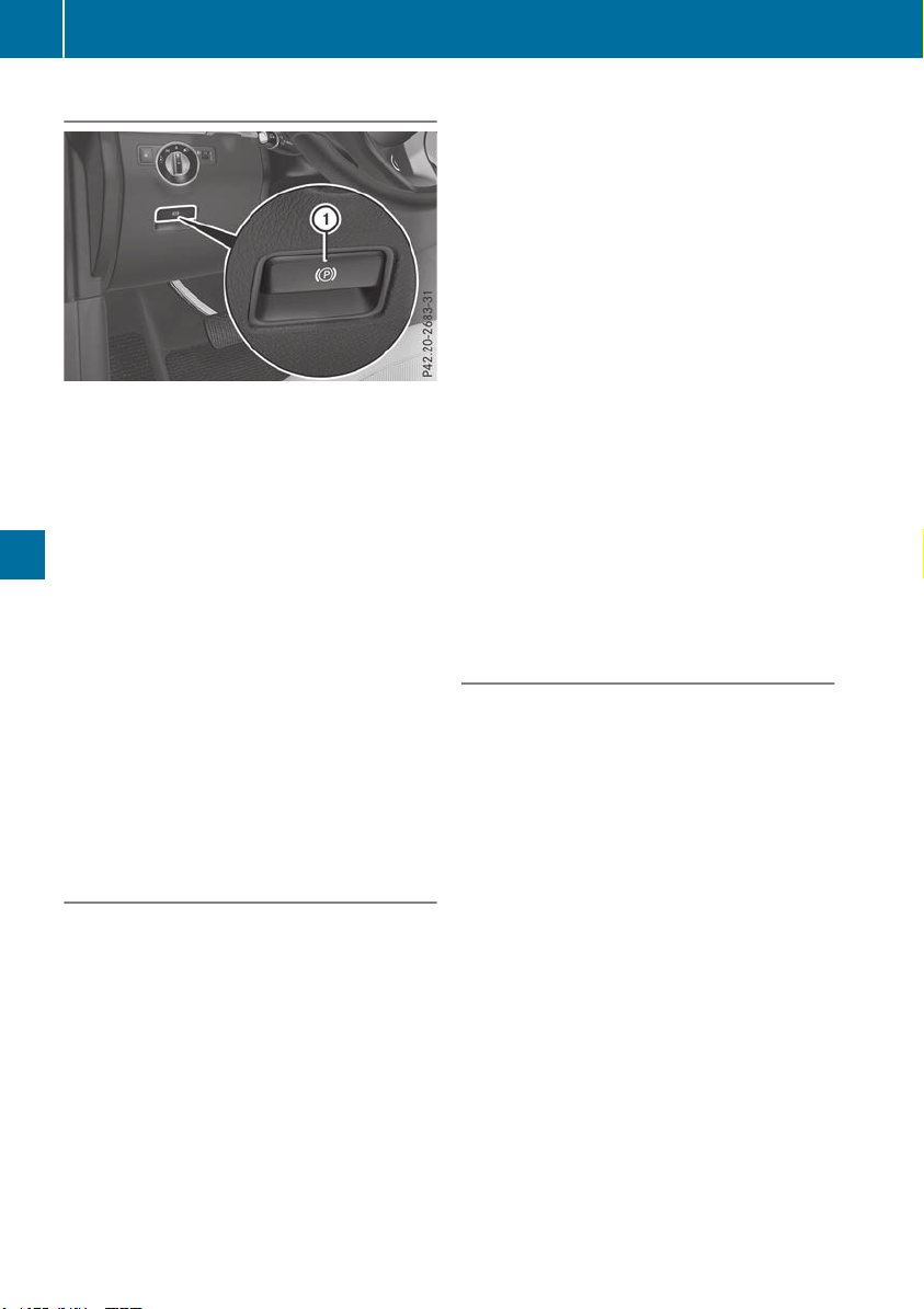
Applying or releasing manually
X
To engage: push handle :.
When the electric parking brake is engaged,
the F (USA only) or ! (Canada only)
red indicator lamp lights up in the instrument
cluster.
i
The electric parking brake can also be
applied when the SmartKey is removed.
X
To release: pull handle :.
The red F (USA only) or ! (Canada
only) indicator lamp in the instrument cluster
goes out.
i The electric parking brake can only be
released:
R
when the SmartKey is in position 1 in the
ignition lock (Y page 135) or
R
if the ignition was switched on using the
Start/Stop button
To ensure that you do not roll backwards when
pulling away on an uphill slope, engage the elec-
tric parking brake (Y page 138).
Applying automatically
The electric parking brake is automatically
applied when the transmission is in position j
and
R
the engine is switched off or
R
the driver is not wearing a seat belt and the
driver's door is opened
To prevent the electric parking brake from being
automatically applied, pull handle :.
The electric parking brake is also applied auto-
matically if:
R
Active Distance Assist DISTRONIC brings the
vehicle to a standstill or
R
the HOLD function is keeping the vehicle sta-
tionary
R
Active Parking Assist or the Parking Package
with rear view camera is keeping the vehicle
stationary
In addition, at least one of the following condi-
tions must be fulfilled:
R
the engine is switched off
R
the driver is not wearing a seat belt and the
driver's door is opened
R
there is a system malfunction
R
the power supply is insufficient
R
the vehicle is stationary for a lengthy period
The red F (USA only) or ! (Canada only)
indicator lamp in the instrument cluster lights
up.
The electric parking brake is not automatically
applied if the engine is switched off by the ECO
start/stop function.
Releasing automatically
The electric parking brake is released automat-
ically when all of the following conditions are
fulfilled:
R
The engine is running.
R
The seat belt tongue is engaged in the belt
buckle.
R
The transmission is in position h or k and
you depress the accelerator pedal or, on a
level surface, you shift from transmission
position j to h or k.
R
If the transmission is in position k, the trunk
lid must be closed.
If the seat belt tongue is not engaged in the seat
belt buckle, the following conditions must be
fulfilled:
R
The driver's door is closed.
R
You are shifting from transmission position
j or have previously driven at speeds
greater than 2 mph (3 km/h).
R
If the transmission is in position k, the trunk
lid must be closed.
When the electric parking brake is released,
the ! indicator lamp goes out in the instru-
ment cluster.
158
Parking
Driving and parking
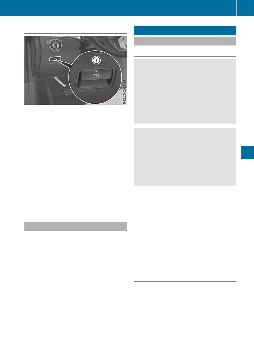
Emergency braking
The vehicle can also be braked during an emer-
gency by using the electric parking brake.
X
While driving, push handle : of the electric
parking brake.
The vehicle is braked for as long as the handle
of the electric parking brake is pressed. The
longer the electric parking brake handle is
depressed, the greater the braking force.
During braking:
R
a warning tone sounds
R
the ReleaseRelease Park.Park. BrakeBrake message appears
R
the red F (USA only) or ! (Canada
only) indicator lamp on the instrument cluster
will flash
When the vehicle has been braked to a stand-
still, the electric parking brake is applied.
Parking the vehicle for a long period
If you leave the vehicle parked for longer than
four weeks, the battery may be damaged by
exhaustive discharging.
If you leave the vehicle parked for longer than six
weeks, the vehicle may suffer damage as a
result of lack of use.
X
Visit a qualified specialist workshop and seek
advice.
i
You can obtain information about trickle
chargers from a qualified specialist work-
shop.
Plug-in hybrid vehicles: observe the notes on
the high-voltage battery in the separate Opera-
tor's Manual.
Driving tips
General notes
Important safety notes
G
WARNING
If you switch off the ignition while driving,
safety-relevant functions are only available
with limitations, or not at all. This could affect,
for example, the power steering and the brake
boosting effect. You will require considerably
more effort to steer and brake. There is a risk
of an accident.
Do not switch off the ignition while driving.
G
WARNING
If you operate mobile communication equip-
ment when driving, you may be distracted
from the traffic situation. You could also lose
control of the vehicle. There is a risk of an
accident.
Only operate this equipment when the vehicle
is stationary.
Observe the legal requirements for the country
in which you are driving. Some jurisdictions pro-
hibit the driver from using a mobile phone while
driving a vehicle.
If you make a call while driving, always use
hands-free mode. Only operate the telephone
when the traffic situation permits. If you are
unsure, pull over to a safe location and stop
before operating the telephone.
Bear in mind that at a speed of only 30 mph
(approximately 50 km/h), the vehicle covers a
distance of 44 ft (approximately 14 m) per sec-
ond.
Drive sensibly – save fuel
Observe the following tips to save fuel:
X
The tires should always be inflated to the rec-
ommended tire pressure.
X
Remove unnecessary loads.
X
Remove roof carriers when they are not nee-
ded.
X
Warm up the engine at low engine speeds.
Driving tips
159
Driving and parking
Z
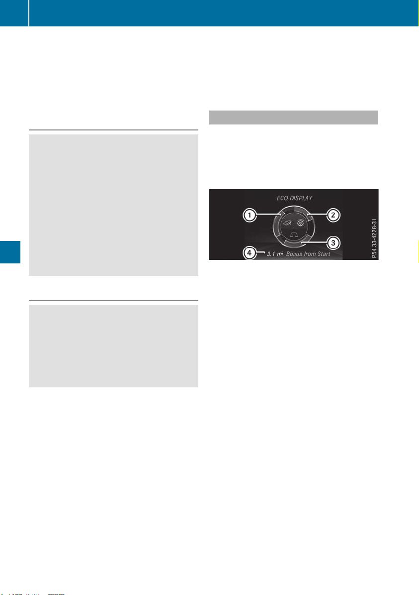
X
Avoid frequent acceleration or braking.
X
Have all service and maintenance work car-
ried out at the specified intervals.
Fuel consumption also increases when driving in
cold weather, in stop-start traffic and in hilly ter-
rain.
Drinking and driving
G
WARNING
Drinking and driving and/or taking drugs and
driving are very dangerous combinations.
Even a small amount of alcohol or drugs can
affect your reflexes, perceptions and judg-
ment.
The possibility of a serious or even fatal acci-
dent is greatly increased when you drink or
take drugs and drive.
Do not drink or take drugs and drive or allow
anyone to drive who has been drinking or tak-
ing drugs.
Emission control
G
WARNING
Combustion engines emit poisonous exhaust
gases such as carbon monoxide. Inhaling
these exhaust gases leads to poisoning. There
is a risk of fatal injury. Therefore never leave
the engine running in enclosed spaces with-
out sufficient ventilation.
Certain engine systems are designed to keep
the level of poisonous components in exhaust
fumes within legal limits.
These systems only work at peak efficiency if
they are serviced exactly in accordance with the
manufacturer's specifications. Always have
work on the engine carried out at a qualified
specialist workshop. Mercedes-Benz recom-
mends that you use an authorized Mercedes-
Benz Center for this purpose. In particular, work
relevant to safety or on safety-related systems
must be carried out at a qualified specialist
workshop.
The engine settings must not be changed under
any circumstances. Furthermore, all specific
service work must be carried out at regular
intervals and in accordance with the Mercedes-
Benz service requirements.
You can obtain current information concerning
the servicing of your vehicle at any time from a
qualified specialist workshop. This could be an
overview of the maintenance work or any addi-
tional maintenance work, for example.
ECO display
The ECO display shows you how economical
your driving style is. The ECO display assists you
in achieving the most economical driving style
for the selected settings and prevailing condi-
tions. Your driving style can significantly influ-
ence the vehicle's consumption.
:
Acceleration
;
Coasting
=
Constant
?
Additional range achieved
Range ? is shown under BonusBonus fr.fr. StartStart and
represents the additional range achieved since
the beginning of the journey as a result of an
adapted driving style.
If the fuel level has dropped into the reserve
range, the Reserve FuelReserve Fuel message is shown in
the multifunction display instead of range ?.
The 8 warning lamp in the instrument cluster
also lights up (Y page 283).
160
Driving tips
Driving and parking

The ECO display consists of three sections, with
an inner and outer area. The sections corre-
spond to the following three categories:
:
Acceleration (evaluation of all accel-
eration processes):
R
the outer area fills up and the inner
area lights up green: moderate
acceleration, especially at higher
speeds
R
the outer area empties and the
inner area is gray: sporty acceler-
ation
;
Coasting (evaluation of all decelera-
tion processes):
R
the outer area fills up and the inner
area lights up green: anticipatory
driving, keeping your distance and
early release of the accelerator.
The vehicle can coast without use
of the brakes.
R
the outer area empties and the
inner area is gray: frequent heavy
braking
=
Constant (continuous evaluation
over the entire journey):
R
the outer area fills up and the inner
area lights up green: constant
speed and avoidance of unneces-
sary acceleration and deceleration
R
the outer area empties and the
inner area is gray: fluctuations in
speed
The three inner areas display the current driving
style and light up green as a result of a particu-
larly economical driving style. Depending on the
driving situation, up to two areas may light up
simultaneously.
At the beginning of the journey, the three outer
areas are empty and fill up as a result of eco-
nomical driving. A higher level indicates a more
economical driving style. If the three outer areas
are completely filled at the same time, the driver
has adopted the most economical driving style
for the selected settings and prevailing condi-
tions. The ECO display border lights up.
The ECO display does not indicate the actual fuel
consumption. The additionally achieved range
displayed under Bonus fr. StartBonus fr. Start does not
indicate a fixed consumption reduction.
In addition to driving style, the actual consump-
tion is affected by other factors, such as:
R
load
R
tire pressure
R
cold start
R
choice of route
R
electrical consumers switched on
These factors are not included in the ECO dis-
play.
An economical driving style specially requires
driving at moderate engine speeds.
Achieving a higher value in the categories
"Acceleration" and "Constant":
R
observe the gearshift recommendations.
R
drive the vehicle in the Comfort drive pro-
gram.
On long journeys at a constant speed, e.g. on the
highway, only the outer area for "constant" will
change.
The ECO display summarizes the driving style
from the start of the journey to its completion.
Therefore, there are more marked changes in
the outer areas at the start of a journey. On lon-
ger journeys, there are fewer changes. For more
marked changes, perform a manual rest
(Y page 233).
For further information on the ECO display, see
(Y page 233).
Braking
Important safety notes
G
WARNING
If you shift down on a slippery road surface in
an attempt to increase the engine's braking
effect, the drive wheels could lose their grip.
There is an increased danger of skidding and
accidents.
Do not shift down for additional engine brak-
ing on a slippery road surface.
Downhill gradients
!
On long and steep gradients, you must
reduce the load on the brakes by shifting to a
lower gear in good time. This allows you to
take advantage of the engine's braking effect.
Driving tips
161
Driving and parking
Z

This helps you to avoid overheating the
brakes and wearing them out excessively.
When you take advantage of engine braking, a
drive wheel may not turn for some time, e.g.
on a slippery road surface. This could cause
damage to the drive train. This type of damage
is not covered by the Mercedes-Benz war-
ranty.
Do not depress the brake pedal continuously
while the vehicle is in motion, e.g. causing the
brakes to rub by constantly applying light pres-
sure to the pedal. This results in excessive and
premature wear to the brake pads.
Use the left-hand steering wheel paddle shifter
to shift into a lower gear in good time on long
and steep downhill gradients. This is especially
important if the vehicle is laden.
This also applies if you have activated cruise
control, the limiter or Active Distance Assist
DISTRONIC.
This will use the braking effect of the engine, so
that less braking will be required to maintain the
speed. This relieves the load on the brake sys-
tem and prevents the brakes from overheating
and wearing too quickly.
Heavy and light loads
G
WARNING
If you rest your foot on the brake pedal while
driving, the braking system can overheat. This
increases the stopping distance and can even
cause the braking system to fail. There is a
risk of an accident.
Never use the brake pedal as a footrest. Never
depress the brake pedal and the accelerator
pedal at the same time.
!
Depressing the brake pedal constantly
results in excessive and premature wear to
the brake pads.
If the brakes have been subjected to a heavy
load, do not stop the vehicle immediately. Drive
on for a short while. This allows the airflow to
cool the brakes more quickly.
Wet roads
If you have driven for a long time in heavy rain
without braking, there may be a delayed reac-
tion from the brakes when braking for the first
time. This may also occur after the vehicle has
been washed or driven through deep water.
You then have to depress the brake pedal more
firmly. Maintain a greater distance from the
vehicle in front.
After driving on a wet road or having the vehicle
washed, brake firmly while paying attention to
the traffic conditions. This will warm up the
brake discs, thereby drying them more quickly
and protecting them against corrosion.
Limited braking performance on salt-
treated roads
If you drive on salted roads, a layer of salt resi-
due may form on the brake discs and brake
pads. This can result in a significantly longer
braking distance.
R
Brake occasionally to remove any possible
salt residue. Make sure that you do not
endanger other road users when doing so.
R
Carefully depress the brake pedal and the
beginning and end of a journey.
R
Maintain a greater distance to the vehicle
ahead.
Servicing the brakes
!
The brake fluid level may be too low, if:
R
if the red brake warning lamp lights up in
the instrument cluster and
R
you hear a warning tone while the engine is
running
Observe additional warning messages in the
multifunction display.
The brake fluid level may be too low due to
brake pad wear or leaking brake lines.
Have the brake system checked immediately.
Consult a qualified specialist workshop to
arrange this.
!
A function or performance test should only
be carried out on a 2-axle dynamometer. If
you wish to operate the vehicle on such a
dynamometer, please consult a qualified spe-
cialist workshop in advance. You could oth-
erwise damage the drive train or the brake
system.
!
Because ESP
®
is an automatic system, the
engine and ignition must be switched off
(SmartKey in position 0 or 1 or Start/Stop
button in position 0 or 1) when the electric
162
Driving tips
Driving and parking

parking brake is being tested on a brake dyna-
mometer (maximum 10 seconds).
Braking triggered automatically by ESP
®
may
seriously damage the brake system.
All checks and maintenance work on the brake
system must be carried out at a qualified spe-
cialist workshop.
Have brake pads installed and brake fluid
replaced at a qualified specialist workshop.
If the brake system has only been subject to
moderate loads, you should test the functional-
ity of your brakes at regular intervals. To do so,
depress the brake pedal firmly when driving at a
high speed. This improves the grip of the brake
pads.
You can find a description of Brake Assist (BAS)
on (Y page 67) or of BAS PLUS on (Y page 72).
Mercedes-Benz recommends that you only have
brake pads/linings installed on your vehicle
which have been approved for Mercedes-Benz
vehicles or which correspond to an equivalent
quality standard. Brake pads/linings which have
not been approved for Mercedes-Benz vehicles
or which are not of an equivalent quality could
affect your vehicle's operating safety.
Mercedes-Benz recommends that you only use
brake fluid that has been specially approved for
your vehicle by Mercedes-Benz, or which corre-
sponds to an equivalent quality standard. Brake
fluid which has not been approved for
Mercedes-Benz vehicles or which is not of an
equivalent quality could affect your vehicle's
operating safety.
High-performance brake system
(Mercedes-AMG vehicles)
The high-performance brake system is designed
for heavy loads. This may lead to noise when
braking. This will depend on:
R
Speed
R
Braking force
R
Environmental conditions, such as tempera-
ture and humidity
The wear of individual components of the brake
system, such as the brake pads/linings or brake
discs, depends on the individual driving style
and operating conditions.
For this reason, it is impossible to state a mile-
age that will be valid under all circumstances. An
aggressive driving style will lead to high wear.
You can obtain further information about this
from your authorized Mercedes-Benz Center.
New and replaced brake pads and discs only
reach their optimum braking effect after several
hundred kilometers of driving. Compensate for
this by applying greater force to the brake pedal.
Keep this in mind, and adapt your driving and
braking accordingly during this break-in period.
Excessive heavy braking results in correspond-
ingly high brake wear. Observe the # brake
wear warning lamp in the instrument cluster and
note any brake status messages in the multi-
function display. Especially for high perform-
ance driving, it is important to maintain and have
the brake system checked regularly.
Driving on wet roads
Hydroplaning
If water has accumulated to a certain depth on
the road surface, there is a danger of hydro-
planing occurring, even if:
R
you drive at low speeds
R
the tires have adequate tread depth
For this reason, in the event of heavy rain or in
conditions in which hydroplaning may occur,
you must drive in the following manner:
R
lower your speed
R
avoid ruts
R
avoid sudden steering movements
R
brake carefully
Driving on flooded roads
!
Do not drive through flooded areas. Check
the depth of any water before driving through
it. Drive slowly through standing water. Oth-
erwise, water could enter the vehicle interior
or engine compartment. It can then damage
the engine's or automatic transmission's
electronic components. It can also be sucked
in by the engine's air intake connection and
cause engine damage.
i
Vehicles with the AIRMATIC Package:
select the raised vehicle level before driving
through a body of water.
Driving tips
163
Driving and parking
Z

Off-road fording
!
Under no circumstances should you accel-
erate before entering the water. The bow
wave could cause water to enter and damage
the engine and other assemblies.
!
Do not open any of the vehicle's doors while
fording. Otherwise, water could get into the
vehicle interior and damage the vehicle's
electronics and interior equipment.
R
Establish how deep the water is and the char-
acteristics of the body of water before ford-
ing.
R
Select the highest possible vehicle level.
R
Shift to a lower gear using the left-hand steer-
ing wheel paddle shifter.
R
Avoid high engine speeds.
R
Enter and exit the water at a flat place and at
a steady walking pace.
R
Drive slowly and at an even speed through the
water.
R
Ensure that a bow wave does not form as you
drive.
R
Do not stop and do not switch off the engine.
Water offers a high degree of resistance, and
the ground is slippery and in some cases
unstable. Therefore, it is difficult and danger-
ous to pull away in the water.
R
Clean any mud from the tire tread after ford-
ing.
R
Apply the brakes to dry them after fording.
Always observe the fording depth values
(Y page 392).
Winter driving
G
WARNING
If you shift down on a slippery road surface in
an attempt to increase the engine's braking
effect, the drive wheels could lose their grip.
There is an increased danger of skidding and
accidents.
Do not shift down for additional engine brak-
ing on a slippery road surface.
G
DANGER
If the exhaust pipe is blocked or adequate
ventilation is not possible, poisonous gases
such as carbon monoxide (CO) may enter the
vehicle. This is the case, e.g. if the vehicle
becomes trapped in snow. There is a risk of
fatal injury.
If you leave the engine or the auxiliary heating
running, make sure the exhaust pipe and area
around the vehicle are clear of snow. To
ensure an adequate supply of fresh air, open a
window on the side of the vehicle that is not
facing into the wind.
!
When scraping ice off the rear window, take
care not to damage the rear-window seal or
trim.
Have your vehicle winter-proofed at a qualified
specialist workshop at the onset of winter.
Drive particularly carefully on slippery road sur-
faces. Avoid sudden acceleration, steering and
braking maneuvers. Do not use cruise control or
Active Distance Assist DISTRONIC.
If the vehicle threatens to skid or cannot be
stopped when moving at low speed:
X
Shift the transmission to position i.
X
Try to bring the vehicle under control using
corrective steering.
When driving in snow with or without snow
chains, select driving program Slippery
(Y page 142).
i
Vehicles with a diesel engine: do not
cover the radiator, e.g. with a protective
cover. The measuring function of the on-
board diagnosis system may otherwise pro-
vide inaccurate values. Some of these values
are required by law and must therefore always
be accurate.
The outside temperature indicator is not
designed to serve as an ice-warning device and
is therefore unsuitable for that purpose.
Changes in the outside temperature are dis-
played after a short delay.
Indicated temperatures just above the freezing
point do not guarantee that the road surface is
free of ice. The road may still be icy, especially in
wooded areas or on bridges. You should pay
special attention to road conditions when tem-
peratures are around the freezing point.
For more information on driving with snow
chains, see (Y page 353).
164
Driving tips
Driving and parking

For more information on driving with summer
tires, see (Y page 353).
Observe the notes in the "Changing a wheel"
section (Y page 371).
Off-road driving
Important safety notes
G
WARNING
If you drive on a steep incline at an angle or
turn when driving on an incline, the vehicle
could slip sideways, tip and rollover. There is a
risk of an accident.
Always drive on a steep incline in the line of
fall (straight up or down) and do not turn the
vehicle.
G
WARNING
Flammable material such as leaves, grass or
twigs may ignite if they come into contact with
hot parts of the exhaust system. There is a risk
of fire.
When driving on an unpaved road or off-road,
check the vehicle underside regularly. In par-
ticular, remove trapped plant parts or other
flammable material. Contact a qualified spe-
cialist workshop immediately if damage is
detected.
G
WARNING
If the vehicle level is high, the vehicle center of
gravity is raised. This could cause the vehicle
to tip over more easily on uphill or downhill
gradients. There is a risk of an accident.
Select the lowest possible vehicle level.
!
There is a risk of damage to the vehicle if:
R
the vehicle becomes stuck, e.g. on a high
curb or an unpaved road
R
you drive too fast over an obstacle, e.g. a
curb, a speed bump or a pothole in the road
R
a heavy object strikes the underbody or
parts of the chassis
In situations like this, the body, the under-
body, chassis parts, wheels or tires could be
damaged without the damage being visible.
Components damaged in this way can unex-
pectedly fail or, in the case of an accident, no
longer withstand the loads they are designed
to.
If the underbody paneling is damaged, com-
bustible materials such as leaves, grass or
twigs can gather between the underbody and
the underbody paneling. If these materials
come in contact with hot parts of the exhaust
system, they can catch fire.
In such situations, have the vehicle checked
and repaired immediately at a qualified spe-
cialist workshop. If on continuing your jour-
ney you notice that driving safety is impaired,
pull over and stop the vehicle immediately,
paying attention to road and traffic condi-
tions. In such cases, consult a qualified spe-
cialist workshop.
When driving off-road, substances such as sand,
mud and water or water mixed with oil may get
into the brakes. This could result in a reduced
braking effect or in total brake failure and also in
increased wear and tear. The braking charac-
teristics change depending on the material
entering the brakes. Clean the brakes after driv-
ing off-road. If you detect a reduced braking
effect or grinding noises, have the brake system
checked in a qualified specialist workshop as
soon as possible. Adapt your driving style to the
different braking characteristics.
Driving off-road increases the likelihood of dam-
age to the vehicle, which, in turn, can lead to
failure of the mechanical assembly or systems.
Adapt your driving style to suit the terrain con-
ditions. Drive carefully. Have damage to the
vehicle rectified immediately at a qualified spe-
cialist workshop.
Do not shift into transmission position i when
driving off-road. You could lose control of the
vehicle if you attempt to brake the vehicle using
the service brake. If the gradient is too steep for
your vehicle, drive back down in reverse gear.
General notes
H
Environmental note
Protection of the environment is of primary
importance. Treat nature with respect.
Observe all prohibiting signs.
Read this section carefully before driving your
vehicle off-road. Practice by driving over more
gentle off-road terrain first.
Driving tips
165
Driving and parking
Z

Familiarize yourself with the characteristics of
your vehicle and the gear shift operation before
driving through difficult terrain.
The following driving systems are specially
adapted to off-road driving:
R
The Off-road drive program (vehicles without
Off-Road Engineering package)
(Y page 215)
R
Off-road and Off-road Plus drive programs
(vehicles with Off-Road Engineering package)
(Y page 216)
R
LOW RANGE off-road gear (vehicles with the
Off-Road Engineering package)
(Y page 217)
R
Differential lock (vehicles with the Off-Road
Engineering package) (Y page 217)
R
Off-road ABS (Y page 67)
R
Off-road 4ETS (Y page 70)
R
Off-road ESP
®
(Y page 72)
R
AIRMATIC package (vehicle level)
(Y page 183)
R
DSR (Downhill Speed Regulation)
(Y page 214)
Observe the following notes:
R
Stop the vehicle before starting to drive along
an off-road route. If necessary, select the off-
road program (Y page 216) or shift to the
LOW RANGE off-road gear (Y page 217).
R
Select a vehicle level that is suitable for the
terrain. To avoid damaging the vehicle, make
sure there is always sufficient ground clear-
ance.
R
Check that items of luggage and loads are
stowed safely and are well secured
(Y page 299).
R
Always keep the engine running and in gear
when driving on a downhill gradient. Activate
DSR (Y page 214).
R
Always keep the engine running and in gear
when driving down an incline.
R
Adapt your speed to the terrain. The rougher,
steeper or more ruts on the terrain, the slower
your speed should be.
R
Do not jump with the vehicle as this will inter-
rupt the vehicle's propulsion.
R
Drive with extreme care on unfamiliar off-road
routes where visibility is poor. For safety rea-
sons, get out of the vehicle first and survey
the off-road route.
R
Look out for obstacles, such as rocks, holes,
tree stumps and furrows.
R
Take care when turning on an uphill or down-
hill slope or when driving across a slope. The
vehicle could otherwise tip over.
R
Always keep the doors, the tailgate, the side
windows and the sliding sunroof closed while
the vehicle is in motion.
R
Do not shift the automatic transmission to
position i.
R
Observe the notes on off-road fording
(Y page 164).
i
Information about retrofitting special all-ter-
rain tires is available from any qualified spe-
cialist workshop.
i
Do not use the HOLD function when driving
off-road, on steep uphill or downhill gradients
or on slippery or loose surfaces. The HOLD
function cannot hold the vehicle on such sur-
faces.
Checklist before driving off-road
!
If the engine oil warning lamp lights up while
the vehicle is in motion, stop the vehicle in a
safe place as soon as possible. Check the
engine oil level. The engine oil warning lamp
warning must not be ignored. Continuing the
journey while the symbol is displayed could
lead to engine damage.
X
Engine oil level: check the engine oil level
and add oil if necessary.
When driving on steep gradients, the engine
oil level must be sufficiently high to ensure a
correct oil supply in the vehicle.
X
DEF tank (BlueTEC vehicles): check the
level and add if necessary (Y page 153).
X
Tire-changing tool kit: check that the jack is
working and make sure you have the lug
wrench, a robust tow cable and a folding
spade in the vehicle.
X
Wheels and tires: check the tread depth and
pressure of the tires.
X
Check for damage and remove any foreign
objects, e.g. small stones, from the wheels/
tires.
X
Replace any missing valve caps.
X
Replace dented or damaged wheels.
X
Rims: dented or bent rims can result in a loss
of tire pressure and damage the tire bead.
166
Driving tips
Driving and parking

Before driving off-road, check the wheels and
replace them if necessary.
Checklist after driving off-road
!
If you detect damage to the vehicle after
driving off-road, have the vehicle checked
immediately at a qualified specialist work-
shop.
Driving over rough terrain places greater
demands on your vehicle than driving on normal
roads. After driving off-road, check the vehicle.
This allows you to detect damage promptly and
reduce the risk of an accident to yourself and
other road users.
X
If the Offroad or Offroad Plus drive program
is selected: select the Individual, Sport,
Comfort or Slippery drive program
(Y page 142).
X
Deactivate the LOW RANGE off-road gear
(Y page 217).
X
Deactivate DSR (Y page 214).
X
Lower the vehicle level again to a level suita-
ble to the road conditions, e.g. to the normal
level.
X
Clean the headlamps and rear lights and
check for damage.
X
Clean the front and rear license plates.
X
Clean the wheels and tires with a water jet
and remove any foreign objects.
X
Clean the wheels, wheel housings and the
vehicle underside with a water jet; check for
any foreign objects and damage.
X
Check whether twigs or other parts of plants
have become trapped. These increase the risk
of fire and can damage fuel pipes, brake
hoses or the rubber bellows of the axle joints
and propeller shafts.
X
After the trip, examine without fail the entire
undercarriage, wheels, tires, brakes, body-
work structure, steering, chassis and exhaust
system for damage.
X
After driving for extended periods across
sand, mud, gravel, water or in similarly dirty
conditions, have the brake discs, wheels,
brake pads/linings and axle joints checked
and cleaned.
X
If you detect strong vibrations after off-road
travel, check for foreign objects in the wheels
and drive train and remove them if necessary.
Foreign objects can disturb the balance and
cause vibrations.
Driving on sand
Observe the following rules when driving on
sand:
R
Select the Offroad drive program (vehicles
with Off-road Engineering Package)
(Y page 216).
R
Select the Offroad drive program (vehicles
without Off-road Engineering Package)
(Y page 215).
R
Select a higher vehicle level.
R
Avoid high engine speeds.
R
Use the left-hand steering wheel paddle
shifter to shift to a lower gear appropriate to
the terrain.
R
Drive quickly to overcome the rolling resist-
ance. Otherwise the vehicle's wheels could
become stuck in loose ground.
R
Drive in the tracks of other vehicles if possi-
ble. Make sure that:
-
the tire ruts are not too deep
-
the sand is sufficiently firm
-
the ground clearance of the vehicle is suf-
ficient.
Tire ruts and gravel roads
!
Check that the ruts are not too deep and
that your vehicle has sufficient clearance.
Otherwise, your vehicle could be damaged or
bottom out and get stuck.
Observe the following rules when driving along
ruts in off-road terrain or on roads with loose
gravel:
R
Select the Offroad drive program (vehicles
with Off-road Engineering Package)
(Y page 216).
R
Select the Offroad drive program (vehicles
without Off-road Engineering Package)
(Y page 215).
R
Select a higher vehicle level.
R
Avoid high engine speeds.
R
Shift to a lower gear using the left-hand steer-
ing wheel paddle shifter.
R
Drive slowly.
R
Where ruts are too deep, drive with the
wheels of one side on the center grassy area,
if possible.
Driving tips
167
Driving and parking
Z
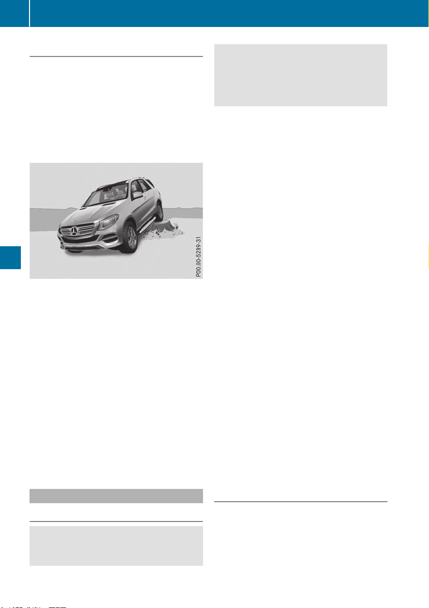
Driving over obstacles
!
Obstacles could damage the floor of the
vehicle or components of the chassis. Ask
passengers for guidance when driving over
large obstacles. The passenger should always
keep a safe distance from the vehicle when
doing so in order to avoid injury as a result of
unexpected vehicle movements. After driving
off-road or over obstacles, check the vehicle
for possible damage, especially to the under-
body and the components of the chassis.
Observe the following rules when driving over
tree stumps, large stones and other obstacles:
R
Select the Offroad drive program (vehicles
with Off-road Engineering Package)
(Y page 216).
R
Select the Offroad drive program (vehicles
without Off-road Engineering Package)
(Y page 215).
R
Select LOW RANGE offroad gear (vehicles
with Off-Road Engineering package)
(Y page 217)
R
Raise the vehicle level.
R
Avoid high engine speeds.
R
Shift to a lower gear using the left-hand steer-
ing wheel paddle shifter.
R
Drive very slowly.
R
Drive straight over the center of obstacles.
Traveling uphill
Approach/departure angle
G
WARNING
If you drive on a steep incline at an angle or
turn when driving on an incline, the vehicle
could slip sideways, tip and rollover. There is a
risk of an accident.
Always drive on a steep incline in the line of
fall (straight up or down) and do not turn the
vehicle.
R
Observe the rules on off-road driving.
R
Do not drive at an angle on slopes, inclines or
gradients, but instead follow the direct line of
fall.
R
When driving down an incline, make use of the
engine's braking effect. Observe the engine
speed; do not overrev the engine.
R
Select the Offroad drive program (vehicles
with Off-road Engineering Package)
(Y page 216).
R
Select the Offroad drive program (vehicles
without Off-road Engineering Package)
(Y page 215).
R
Before driving on extreme uphill and downhill
gradients, select the LOW RANGE offroad
gear (vehicles with Off-road Engineering
Package) (Y page 217).
R
Drive slowly.
R
Avoid high engine speeds. Drive at appropri-
ate engine speeds (maximum 3,000 rpm).
R
Use the left-hand steering wheel paddle
shifter to shift into a lower gear in good time
on long and steep downhill gradients.
R
Check the brakes after prolonged off-road
driving.
Hill start assist will aid you when pulling away on
a hill. For further information about hill start
assist, see (Y page 139).
Do not shift into transmission position i when
driving off-road. You could lose control of the
vehicle if you attempt to brake the vehicle using
the service brake. If the gradient is too steep for
your vehicle, drive back down in reverse gear.
Always observe the approach/departure angle
values (Y page 393).
Maximum gradient-climbing capability
Always observe the maximum gradient climbing
ability values (Y page 393).
168
Driving tips
Driving and parking

Hilltops
When driving up an uphill gradient, slightly
reduce pressure on the accelerator immediately
before reaching the brow of the hill. Make use of
the vehicle's own impetus to travel over the
brow.
This style of driving prevents:
R
the vehicle from lifting off the ground on the
brow of a hill
R
the vehicle from traveling too quickly down
the other side
Driving downhill
R
Drive slowly.
R
Do not drive at an angle down steep inclines.
Steer into the line of fall and drive with the
front wheels aligned straight. Otherwise, the
vehicle could slip sideways, tip and rollover.
R
Shift to a lower gear using the left-hand pad-
dle shifter before tackling steep downhill gra-
dients.
R
Activate DSR. If this is not sufficient, brake
gently. When doing so, make sure that the
vehicle is facing in the direction of the line of
fall.
R
Check that the brakes are working normally
after a long downhill stretch.
i
The special off-road ABS setting enables a
precise, brief and repeated locking of the
front wheels. This causes them to dig into
loose earth. Be aware that the front wheels
easily skid across the ground surface if com-
pletely braked and therefore lose their ability
to steer.
Driving systems
Intelligent Drive
Mercedes-Benz Intelligent Drive stands for inno-
vative driver assistance and safety systems
which enhance comfort and support the driver in
critical situations. With these intelligent co-ordi-
nated systems Mercedes-Benz has set a mile-
stone on the path towards autonomous driving.
Mercedes-Benz Intelligent Drive embraces all
elements of active and passive safety in one well
thought out system – for the safety of the vehi-
cle occupants and that of other road users.
Further information on driving safety systems
(Y page 66).
Cruise control
General notes
Cruise control maintains a constant road speed
for you. It brakes automatically in order to avoid
exceeding the set speed. You must select a
lower gear in good time on long and steep down-
hill gradients, especially if the vehicle is laden or
towing a trailer. By doing so, you will make use of
the braking effect of the engine. This relieves the
load on the brake system and prevents the
brakes from overheating and wearing too
quickly.
Use cruise control only if road and traffic con-
ditions make it appropriate to maintain a steady
speed for a prolonged period. You can store any
road speed above 20 mph (30 km/h).
i
Cruise control should not be activated when
driving off-road.
Important safety notes
If you fail to adapt your driving style, cruise con-
trol can neither reduce the risk of an accident
nor override the laws of physics. Cruise control
cannot take into account the road, traffic and
weather conditions. Cruise control is only an
aid. You are responsible for the distance to the
vehicle in front, for vehicle speed, for braking in
good time and for staying in your lane.
Do not use cruise control:
R
in road and traffic conditions which do not
allow you to maintain a constant speed, e.g. in
heavy traffic or on winding roads
R
on slippery road surfaces. Braking or accel-
erating could cause the drive wheels to lose
traction and the vehicle could then skid
R
when there is poor visibility, e.g. due to fog,
heavy rain or snow
If there is a change of drivers, advise the new
driver of the speed stored.
Driving systems
169
Driving and parking
Z
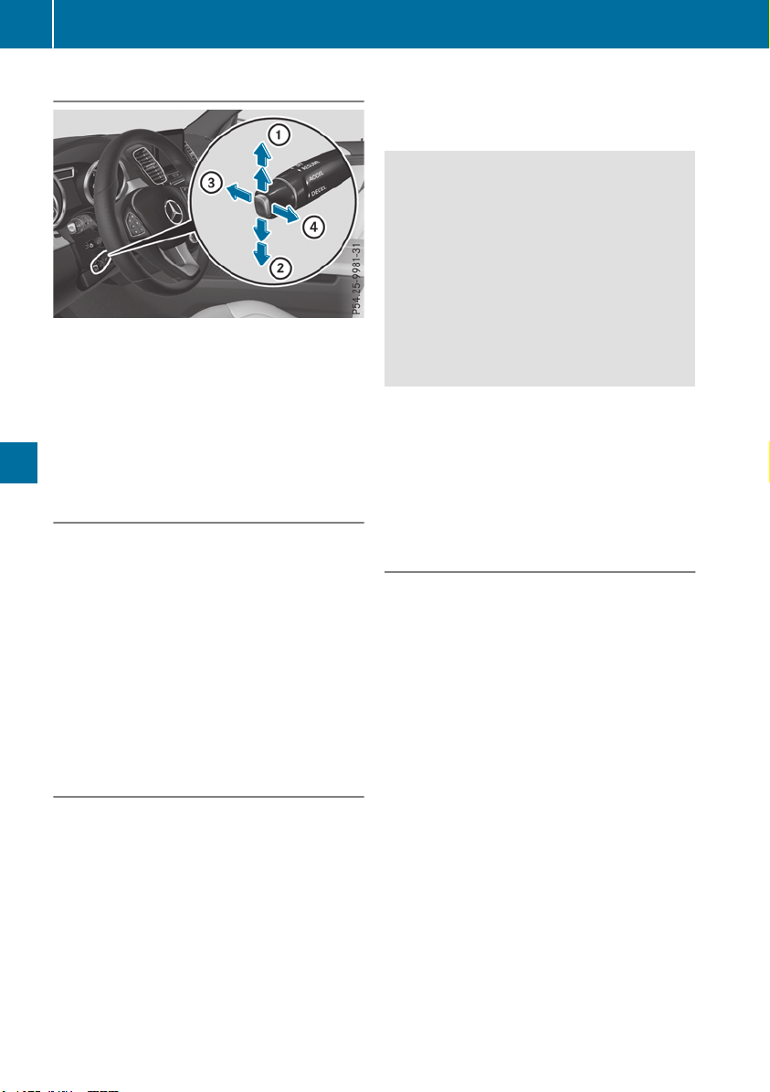
Cruise control lever
:
Activates or increases speed
;
Activates or reduces speed
=
Deactivates cruise control
?
Activates at the current speed/last stored
speed
When you activate cruise control, the stored
speed is shown in the multifunction display for
five seconds.
Activation conditions
To activate cruise control, all of the following
activation conditions must be fulfilled:
R
the electric parking brake must be released.
R
you are driving faster than 20 mph (30 km/h).
R
ESP
®
must be active, but not intervening.
R
the transmission must be in position h.
R
DSR must be deactivated.
R
the Offroad Plus drive program must be deac-
tivated (vehicles with the Off-road Engineer-
ing Package).
Storing, maintaining and calling up a
speed
Storing and maintaining a speed
X
Accelerate the vehicle to the desired speed.
X
Briefly press the cruise control lever up : or
down ?.
X
Remove your foot from the accelerator pedal.
Cruise control is activated. The vehicle auto-
matically maintains the stored speed.
i
Cruise control may be unable to maintain
the stored speed on uphill gradients. The
stored speed is resumed when the gradient
evens out. Cruise control maintains the
stored speed on downhill gradients by auto-
matically applying the brakes.
Storing or calling up a speed
G
WARNING
If you call up the stored speed and it differs
from the current speed, the vehicle acceler-
ates or decelerates. If you do not know the
stored speed, the vehicle could accelerate or
brake unexpectedly. There is a risk of an acci-
dent.
Pay attention to the road and traffic condi-
tions before calling up the stored speed. If you
do not know the stored speed, store the
desired speed again.
X
Briefly pull the cruise control lever towards
you =.
X
Remove your foot from the accelerator pedal.
Cruise control is operational and when first
activated stores the current speed or regu-
lates the speed of the vehicle to the stored
speed.
Setting a speed
Keep in mind that it may take a brief moment
until the vehicle has accelerated or braked to
the speed set.
X
Press the cruise control lever up : for a
higher speed or down ; for a lower speed.
X
To adjust the set speed in 1 mph incre-
ments (1 km/h increments): briefly press
the cruise control lever up : or down ; to
the pressure point.
Every time the cruise control lever is pressed
up : or down ; the last speed stored is
increased or reduced.
X
To adjust the set speed in 5 mph incre-
ments (10 km/h increments): briefly press
the cruise control lever up : or down ;
beyond the pressure point.
Every time the cruise control lever is pressed
up : or down ; the last speed stored is
increased or reduced.
i
Cruise control is not deactivated if you
depress the accelerator pedal. For example, if
you accelerate briefly to overtake, cruise con-
trol adjusts the vehicle's speed to the last
speed stored after you have finished overtak-
ing.
170
Driving systems
Driving and parking

Deactivating cruise control
There are several ways to deactivate cruise con-
trol:
X
Briefly press the cruise control lever for-
wards :.
or
X
Brake.
Cruise control is automatically deactivated if:
R
you engage the electric parking brake
R
you are driving at less than 20 mph (30 km/h)
R
ESP
®
intervenes or you deactivate ESP
®
R
you activate DSR
R
you activate the Offroad Plus program (vehi-
cles with the Off-road Engineering Package)
R
you shift the transmission to position i
while driving
If cruise control is deactivated, you will hear a
warning tone. You will see the Cruise Con‐Cruise Con‐
trol Offtrol Off message in the multifunction display
for approximately five seconds.
i
When you switch off the engine, the last
speed stored is cleared.
Active Distance Assist DISTRONIC
General notes
Active Distance Assist DISTRONIC regulates the
speed and automatically helps you maintain the
distance from the vehicle detected in front.
Vehicles are detected with the aid of the radar
sensor system. Active Distance Assist
DISTRONIC brakes automatically so that the set
speed is not exceeded.
You must select a lower gear in good time on
long and steep downhill gradients, especially if
the vehicle is laden or towing a trailer. By doing
so, you will make use of the braking effect of the
engine. This relieves the load on the brake sys-
tem and prevents the brakes from overheating
and wearing too quickly.
If Active Distance Assist DISTRONIC detects
that there is a risk of a collision with the vehicle
in front, you will be warned visually and audibly.
Active Distance Assist DISTRONIC cannot pre-
vent a collision without your intervention. An
intermittent warning tone will then sound and
the distance warning lamp will light up in the
instrument cluster. Brake immediately in order
to increase the distance to the vehicle in front or
take evasive action provided it is safe to do so.
For Active Distance Assist DISTRONIC to assist
you when driving, the radar sensor system must
be operational.
Active Distance Assist DISTRONIC operates in
the speed range between 0 mph (0 km/h) and
120 mph (200 km/h).
Do not use Active Distance Assist DISTRONIC
while driving on roads with steep gradients.
As Active Distance Assist DISTRONIC transmits
radar waves, it can resemble the radar detectors
of the responsible authorities. You can refer to
the relevant chapter in the Operator's Manual if
questions are asked about this.
i
USA only:
This device has been approved by the FCC as
a "Vehicular Radar System". The radar sensor
is intended for use in an automotive radar
system only. Removing, tampering with, or
altering the device will void any warranties,
and is not permitted by the FCC. Do not tam-
per with, alter, or use in any non-approved
way.
Any unauthorized modification to this device
could void the user's authority to operate the
equipment.
i
Canada only: This device complies with
RSS-210 of Industry Canada. Operation is
subject to the following two conditions:
1. This device may not cause interference,
and
2. This device must accept any interference
received, including interference that may
cause undesired operation of the device.
Do not tamper with, alter or use in any non-
approved way.
Any unauthorized modification to this device
could void the user's authority to operate the
equipment.
Driving systems
171
Driving and parking
Z

Important safety notes
G
WARNING
Active Distance Assist DISTRONIC does not
react to:
R
people or animals
R
stationary objects in the road, e.g. stopped
or parked vehicles
R
oncoming vehicles and crossing traffic
As a result, Active Distance Assist DISTRONIC
may neither give warnings nor intervene in
such situations. There is a risk of an accident.
Always pay careful attention to the traffic sit-
uation and be ready to brake.
G
WARNING
Active Distance Assist DISTRONIC cannot
always clearly identify other road users and
complex traffic situations.
In such cases, Active Distance Assist
DISTRONIC can:
R
give an unnecessary warning and then
brake the vehicle
R
neither give a warning nor intervene
R
accelerate or brake unexpectedly
There is a risk of an accident.
Continue to drive carefully and be ready to
brake, especially if Active Distance Assist
DISTRONIC warns you.
G
WARNING
Active Distance Assist DISTRONIC brakes
your vehicle with up to 50% of the maximum
possible deceleration. If this deceleration is
not sufficient, Active Distance Assist
DISTRONIC alerts you with a visual and acous-
tic warning. There is a risk of an accident.
Adjust your speed in these cases and main-
tain sufficient distance.
Apply the brakes yourself and/or take evasive
action.
!
When Active Distance Assist DISTRONIC or
the HOLD function is activated, the vehicle
brakes automatically in certain situations.
To avoid damage to the vehicle, deactivate
Active Distance Assist DISTRONIC and the
HOLD function in the following or similar sit-
uations:
R
when towing the vehicle
R
in the car wash
Active Distance Assist DISTRONIC:
R
Can neither reduce the risk of accident nor
override the laws of physics if you fail to adapt
your driving style.
R
Cannot take into account road, weather or
traffic conditions.
R
Is only an aid.
You are responsible for the distance to the vehi-
cle in front, for vehicle speed, for braking in good
time and for staying in your lane.
Do not use Active Distance Assist DISTRONIC:
R
In road and traffic conditions which do not
allow you to maintain a constant speed, e.g. in
heavy traffic or on winding roads
R
On icy or slippery roads; braking or acceler-
ating can cause the drive wheels to lose trac-
tion and the vehicle could then skid
R
In poor visibility, e.g. due to fog, heavy rain or
snow
Active Distance Assist DISTRONIC may not
detect narrow vehicles driving in front, e.g.
motorcycles, or vehicles driving in a staggered
formation.
In particular, the detection of obstacles can be
impaired if:
R
There is dirt on the sensors or anything else
covering the sensors
R
There is snow or heavy rain
R
There is interference by other radar sources
R
There are strong radar reflections, for exam-
ple in parking garages
If Active Distance Assist DISTRONIC no longer
detects a vehicle in front, Distance Pilot
DISTRONIC may unexpectedly accelerate to the
speed stored.
This speed may:
R
Be too high if you are driving in a turning lane
or an exit lane
R
Be so high when driving in the right-hand lane
that you overtake vehicles in the left-hand
lane
R
Be so high in the left lane that you pass vehi-
cles driving on the right
172
Driving systems
Driving and parking
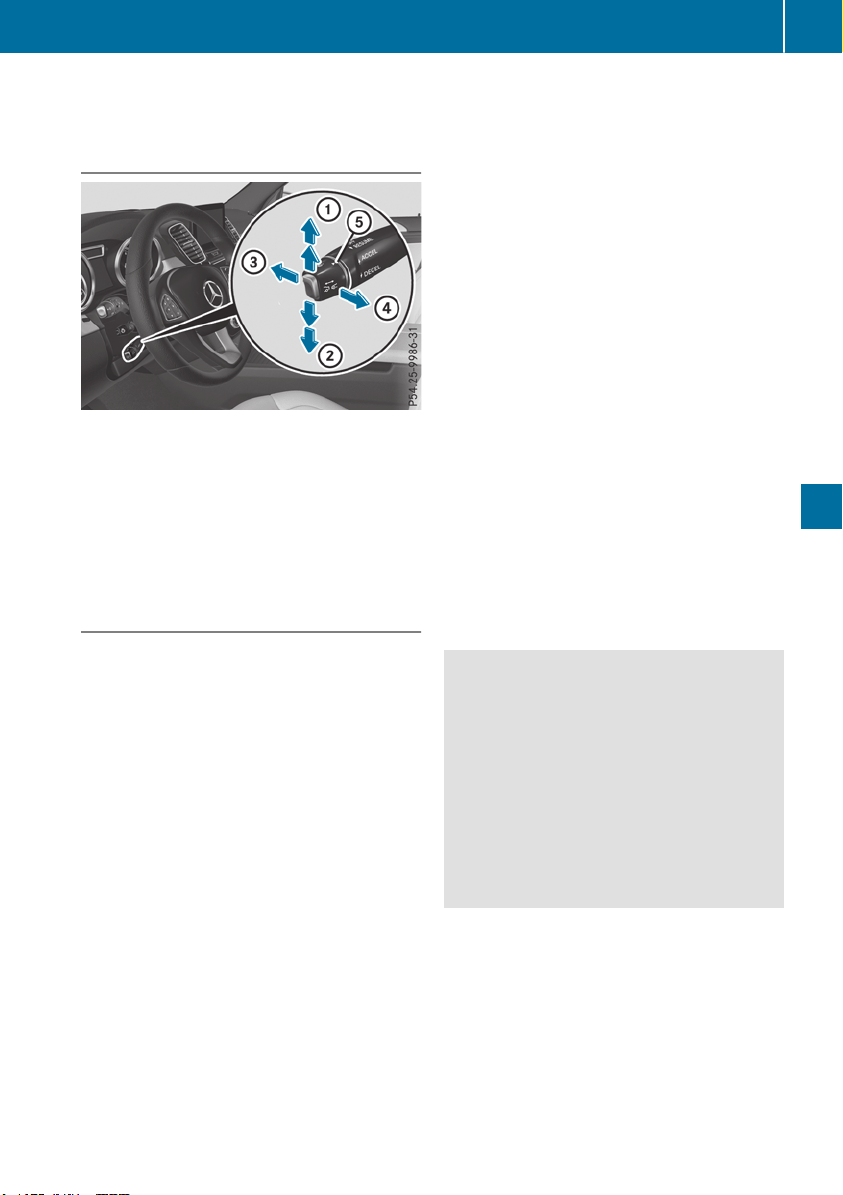
If there is a change of drivers, advise the new
driver of the speed stored.
Cruise control lever
:
Activates or increases speed
;
Activates or reduces speed
=
Deactivates Active Distance Assist
DISTRONIC
?
Activates at the current speed or last stored
speed
A
Sets a specified minimum distance
Activating Active Distance Assist
DISTRONIC
Activation conditions
To activate Active Distance Assist DISTRONIC,
the following conditions must be fulfilled:
R
the engine must be started. It may take up to
two minutes of driving before Active Distance
Assist DISTRONIC is ready for use.
R
the electric parking brake must be released.
R
ESP
®
must be active, but not intervening.
R
the transmission must be in position h.
R
the driver's door must be closed when you
shift from j to h or your seat belt must be
fastened.
R
the front-passenger door and rear doors must
be closed.
R
the Offroad Plus drive program must be deac-
tivated (vehicles with the Off-road Engineer-
ing Package).
R
DSR must be deactivated.
R
the vehicle must not skid.
Activating
X
Briefly pull the cruise control lever towards
you =, up : or down ?.
Active Distance Assist DISTRONIC is activa-
ted.
X
Remove your foot from the accelerator pedal.
Your vehicle adapts its speed to that of the
vehicle in front, but only up to the desired
stored speed.
i
If you do not fully release the accelerator
pedal, the Act.Act. DistanceDistance AssistAssist Suspen‐Suspen‐
dedded message will appears on the multifunc-
tion display. The set distance to a slower-
moving vehicle in front will then not be main-
tained. You will be driving at the speed you
determine by the position of the accelerator
pedal.
You can also activate Active Distance Assist
DISTRONIC when stationary. The lowest speed
that can be set is 20 mph (30 km/h).
X
Briefly pull the cruise control lever towards
you =, up : or down ? .
Active Distance Assist DISTRONIC is activa-
ted.
Activating at the current speed or last
stored speed
G
WARNING
If you call up the stored speed and it differs
from the current speed, the vehicle acceler-
ates or decelerates. If you do not know the
stored speed, the vehicle could accelerate or
brake unexpectedly. There is a risk of an acci-
dent.
Pay attention to the road and traffic condi-
tions before calling up the stored speed. If you
do not know the stored speed, store the
desired speed again.
X
Briefly pull the cruise control lever towards
you =.
X
Remove your foot from the accelerator pedal.
The first time Active Distance Assist
DISTRONIC is activated, it stores the current
speed or regulates the speed of the vehicle to
the previously stored speed.
Driving systems
173
Driving and parking
Z

Driving with Active Distance Assist
DISTRONIC
Pulling away and driving
X
If you want to pull away with Active Dis-
tance Assist DISTRONIC: remove your foot
from the brake pedal.
X
Briefly pull the cruise control lever towards
you ?.
or
X
Accelerate briefly.
Your vehicle pulls away and adapts its speed
to that of the vehicle in front. If no vehicle is
detected in front, your vehicle accelerates to
the set speed.
The vehicle can also pull away when it is facing
an unidentified obstacle or is driving on a differ-
ent line from another vehicle. The vehicle then
brakes automatically.
If there is no vehicle in front, Active Distance
Assist DISTRONIC operates in the same way as
cruise control.
If Active Distance Assist DISTRONIC detects a
slower-moving vehicle in front, it brakes your
vehicle. In this way, the distance you have selec-
ted is maintained.
If Active Distance Assist DISTRONIC detects a
faster-moving vehicle in front, it increases the
driving speed. However, the vehicle is only
accelerated up to the speed you have stored.
Selecting the drive program
Active Distance Assist DISTRONIC supports a
sporty driving style if you have selected the
Sport or Sport Plus drive program
(Y page 146). Acceleration behind the vehicle in
front or to the set speed is then noticeably more
dynamic. If you have selected the Comfort drive
program, the vehicle accelerates more gently.
This setting is recommended in stop-and-start
traffic.
Changing lanes
If you change to the overtaking lane, Active Dis-
tance Assist DISTRONIC helps you if:
R
you are driving faster than 45 mph (70 km/h)
R
you switch on the appropriate turn signal
R
Active Distance Assist DISTRONIC does not
currently detect a danger of collision
If these conditions are fulfilled, your vehicle is
accelerated. Acceleration will be interrupted if
changing lanes takes too long or if the distance
between your vehicle and the vehicle in front
becomes too small.
i
When you change lanes, Active Distance
Assist DISTRONIC monitors the right lane (in
left-side traffic) or the left lane (in right-side
traffic).
Stopping
G
WARNING
If you leave the driver's seat when the vehicle
is only being braked by Active Distance Assist
DISTRONIC, it could roll away:
R
if there is a malfunction in the system or in
the voltage supply
R
if Active Distance Assist DISTRONIC is
deactivated using the cruise control lever,
for example by a vehicle occupant or from
outside the vehicle
R
if the electrical system in the engine com-
partment, the battery or the fuses are tam-
pered with
R
if the battery is disconnected
R
if the vehicle is accelerated, e.g. by a vehi-
cle occupant
There is a risk of an accident.
Always deactivate Active Distance Assist
DISTRONIC and secure the vehicle against
rolling away before you leave it.
If Active Distance Assist DISTRONIC detects
that the vehicle in front is stopping, it brakes
your vehicle until it is stationary.
Once your vehicle is stationary, it remains sta-
tionary and you do not need to depress the
brake.
After a time, the electric parking brake secures
the vehicle and relieves the service brake.
Depending on the specified minimum distance,
your vehicle will come to a standstill at a suffi-
cient distance behind the vehicle in front. The
specified minimum distance is set using the
control on the cruise control lever.
174
Driving systems
Driving and parking
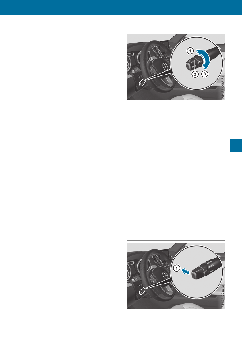
When Active Distance Assist DISTRONIC is acti-
vated and the vehicle is at a standstill, the trans-
mission will be shifted automatically to position
j if:
R
the driver's door is open and the driver's seat
belt is unfastened.
R
the engine is switched off, unless it is auto-
matically switched off by the ECO start/stop
function.
When Active Distance Assist DISTRONIC is acti-
vated and the vehicle is at a standstill, the elec-
tric parking brake will secure the vehicle auto-
matically if:
R
a system malfunction occurs
R
the power supply is not sufficient
On steep uphill or downhill inclines or if there is
a malfunction, the transmission may also be
automatically shifted into position j.
Setting a speed
Keep in mind that it may take a brief moment
until the vehicle has accelerated or braked to
the speed set.
X
Press the cruise control lever up : for a
higher speed or down A for a lower speed
X
To adjust the set speed in 1 mph incre-
ments (1 km/h increments): briefly press
the cruise control lever up : or down ; to
the pressure point.
Every time the cruise control lever is pressed
up : or down ; the last speed stored is
increased or reduced.
X
To adjust the set speed in 5 mph incre-
ments (10 km/h increments): briefly press
the cruise control lever up : or down ;
beyond the pressure point.
Every time the cruise control lever is pressed
up : or down ;, the last speed stored is
increased or reduced.
i
If you accelerate to overtake, Active Dis-
tance Assist DISTRONIC adjusts the vehicle's
speed to the last speed stored after you have
finished overtaking.
Setting a specified minimum distance
You can set the specified minimum distance for
Active Distance Assist DISTRONIC by varying
the time span between one and two seconds.
This determines the distance that Active Dis-
tance Assist DISTRONIC is to maintain from the
vehicle in front, depending on the road speed.
You can see this distance in the multifunction
display (Y page 176).
X
To increase: turn control ; in direction =.
Active Distance Assist DISTRONIC then main-
tains a greater distance between your vehicle
and the vehicle in front.
X
To decrease: turn control ; in direction :.
Active Distance Assist DISTRONIC then main-
tains a shorter distance between your vehicle
and the vehicle in front.
i
Make sure that you maintain a sufficiently
safe distance from the vehicle in front. Adjust
the distance to the vehicle in front if neces-
sary.
Deactivating Active Distance Assist
DISTRONIC
Driving systems
175
Driving and parking
Z
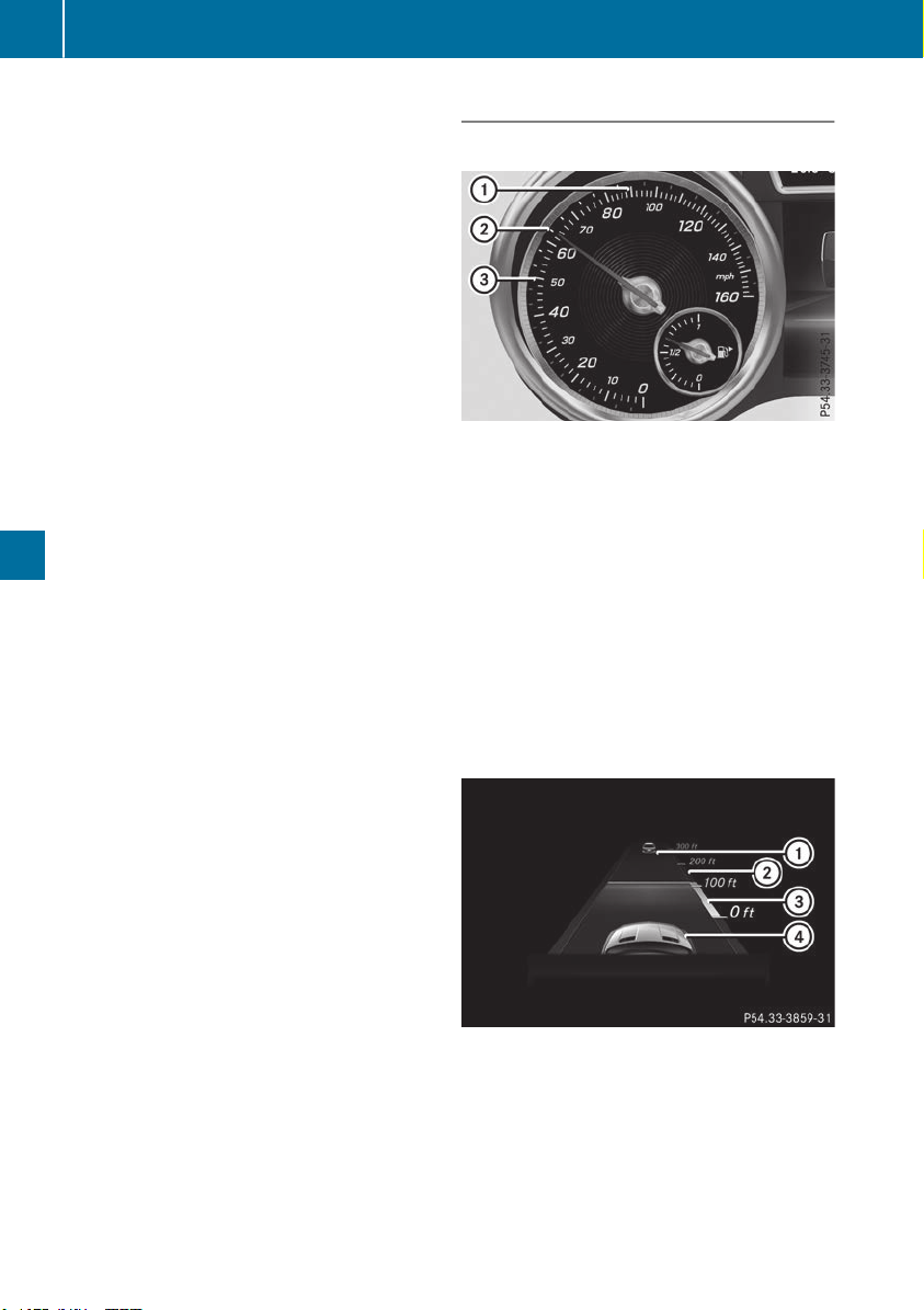
There are several ways to deactivate Active Dis-
tance Assist DISTRONIC:
X
Briefly press the cruise control lever for-
wards :.
or
X
Brake, unless the vehicle is stationary
When you deactivate Active Distance Assist
DISTRONIC, the Active Distance AssistActive Distance Assist
OffOff message will appear on the multifunction
display for approximately five seconds.
i
The last speed stored remains stored until
you switch off the engine.
i
Active Distance Assist DISTRONIC is not
deactivated if you depress the accelerator
pedal. If you accelerate to overtake, Active
Distance Assist DISTRONIC adjusts the vehi-
cle's speed to the last speed stored after you
have finished overtaking.
Active Distance Assist DISTRONIC is automati-
cally deactivated if:
R
you engage the electric parking brake or if the
vehicle is automatically secured with the elec-
tric parking brake
R
ESP
®
intervenes or you deactivate ESP
®
R
the transmission is in position j, k or i
R
you pull the cruise control lever towards you
in order to pull away and the front-passenger
door or one of the rear doors is open
R
you switch on Active Parking Assist or the
Parking Package with rear view camera
R
the vehicle is skidding
A warning tone sounds. The ActiveActive DistanceDistance
Assist OffAssist Off will appear on the multifunction
display for approximately five seconds.
Active Distance Assist DISTRONIC will automat-
ically be deactivated if:
R
you activate DSR
R
you activate the OFFROAD Program+ (vehi-
cles with the Off-road Engineering Package)
The à DSR symbol appears in the multifunc-
tion display.
Displays in the instrument cluster
Displays in the speedometer
Active Distance Assist DISTRONIC displays on the
speedometer (example)
When Active Distance Assist DISTRONIC is acti-
vated, one or two segments ; in the set speed
range light up.
If Active Distance Assist DISTRONIC detects a
vehicle in front, segments ; from speed of the
vehicle in front = to stored speed : light up.
i
For design reasons, the speed displayed on
the speedometer may differ slightly from the
speed set for Active Distance Assist
DISTRONIC.
Assistant display when Active Distance
Assist DISTRONIC is deactivated
:
Vehicle in front, if detected
;
Distance indicator, current distance to the
vehicle in front
=
Specified minimum distance to the vehicle
in front; adjustable
?
Your vehicle
X
Select the Assistance GraphicAssistance Graphic function
using the on-board computer (Y page 237).
176
Driving systems
Driving and parking
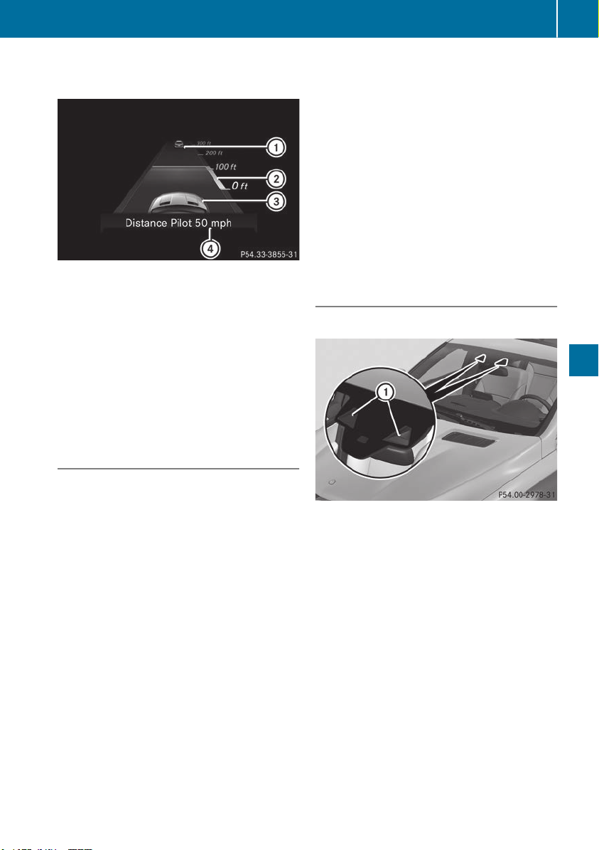
Assistant display when Active Distance
Assist DISTRONIC is activated
:
Vehicle in front, if detected
;
Specified minimum distance to the vehicle
in front; adjustable
=
Your vehicle
?
Active Distance Assist DISTRONIC active
X
Select the Assistance GraphicAssistance Graphic function
using the on-board computer (Y page 237).
You will see the stored speed for approximately
five seconds when you activate Active Distance
Assist DISTRONIC.
Tips for driving with Active Distance
Assist DISTRONIC
General notes
Pay particular attention in the following traffic
situations:
R
Cornering, entering and exiting a bend: the
ability of Active Distance Assist DISTRONIC to
detect vehicles on bends is limited. Your vehi-
cle may brake unexpectedly or late.
R
Vehicles driving in a staggered formation:
Active Distance Assist DISTRONIC may not
detect vehicles that are not driving in the mid-
dle of their lanes. The distance to the vehicle
in front will be too short.
R
Other vehicles changing lane: Active Distance
Assist DISTRONIC has not detected the vehi-
cle cutting in yet. The distance to this vehicle
will be too short.
R
Narrow vehicles: Active Distance Assist
DISTRONIC has not yet detected the vehicle
in front on the edge of the road because of its
narrow width. The distance to the vehicle in
front will be too short.
R
Obstacles and stationary vehicles: Active Dis-
tance Assist DISTRONIC does not brake for
obstacles or stationary vehicles. If, for exam-
ple, the detected vehicle turns a corner and
an obstacle or stationary vehicle is revealed,
Active Distance Assist DISTRONIC will not
brake for them.
R
Crossing vehicles: Active Distance Assist
DISTRONIC may mistakenly detect vehicles
that are crossing your lane. Activating Active
Distance Assist DISTRONIC at, for example, a
traffic light with crossing traffic could cause
your vehicle to pull away at the wrong time.
In such situations, brake if necessary. Active
Distance Assist DISTRONIC will then be deacti-
vated.
Active Distance Assist DISTRONIC with
Active Steering Assist
General notes
Active Distance Assist DISTRONIC with Active
Steering Assist aids you in keeping the vehicle in
the center of the driving lane by means of mod-
erate steering interventions in a speed range
from 0 - 125 mph (0 - 200 km/h).
It monitors the area in front of your vehicle by
means of camera system : at the top of the
windshield.
In a speed range from 0 - 37 mph (0 - 60 km/h),
the advanced automatic pulling away function
focuses on the vehicle in front, taking into
account lane markings, e.g. when following vehi-
cles in a traffic jam.
At speeds of more than 37 mph (60 km/h),
Active Steering Assist focuses on clear lane
markings (left and right), focusing on the vehicle
in front only if clear lane markings are not pres-
ent.
If these conditions are not present, Active Steer-
ing Assist cannot provide assistance.
Driving systems
177
Driving and parking
Z

Active Distance Assist DISTRONIC must be
active in order for the function to be available.
Important safety notes
Active Distance Assist DISTRONIC with Active
Steering Assist can neither reduce the risk of an
accident if you fail to adapt your driving style,
nor override the laws of physics. It cannot take
into account road, weather or traffic conditions.
Active Distance Assist DISTRONIC with Active
Steering Assist is only an aid. You are responsi-
ble for the distance to the vehicle in front, for
vehicle speed, for braking in good time and for
staying in your lane.
Active Distance Assist DISTRONIC with Active
Steering Assist does not detect road and traffic
conditions and does not detect all road users. If
you are following a vehicle which is driving
towards the edge of the road, your vehicle could
come into contact with the curb or other road
boundaries. Be particularly aware of other road
users, e.g. cyclists, that are directly next to your
vehicle.
Obstacles such as traffic pylons on the lane or
projecting out into the lane are not detected.
An inappropriate steering intervention, e.g. after
intentionally driving over a lane marking, can be
corrected at any time if you steer slightly in the
opposite direction.
Active Distance Assist DISTRONIC with Active
Steering Assist cannot continuously keep your
vehicle in lane. In some cases, the steering
intervention is not sufficient to bring the vehicle
back to the lane. In such cases, you must steer
the vehicle yourself to ensure that it does not
leave the lane.
The support provided by the system can be
impaired if:
R
there is poor visibility, e.g. due to insufficient
illumination of the road, or due to snow, rain,
fog or heavy spray
R
there is glare, e.g. from oncoming traffic, the
sun or reflection from other vehicles (e.g. if
the road surface is wet)
R
the windshield is dirty, fogged up, damaged or
covered, for instance by a sticker, in the vicin-
ity of the camera
R
there are no or several unclear lane markings
for one lane, e.g. roadworks
R
the lane markings are worn away, dark or cov-
ered up, e.g. by dirt or snow
R
the distance to the vehicle in front is too short
and thus the lane markings cannot be detec-
ted
R
the lane markings change quickly, e.g. lanes
branch off, cross one another or merge
R
the road is narrow and winding
R
there are highly variable shade conditions on
the roadway
The system is switched to passive and no longer
assists you by performing steering interventions
if:
R
you actively change lane
R
you switch on the turn signal
R
you take your hands off the steering wheel or
do not steer for a prolonged period of time
i
Once you have finished changing lanes,
Active Steering Assist automatically reacti-
vates.
Active Steering Assist cannot provide assis-
tance:
R
on very sharp corners
R
when towing a trailer
R
when a loss of tire pressure or a defective tire
has been detected and displayed
Observe the important safety notes on Active
Distance Assist DISTRONIC (Y page 172).
The steering interventions are carried out with a
limited steering moment. The system requires
the driver to keep his hands on the steering
wheel and to steer himself.
If you do not steer yourself or if you take your
hands off the steering wheel for a prolonged
period of time, the system will first alert you with
a visual warning. A steering wheel symbol
appears in the multifunction display. If you have
still not started to steer and have not taken hold
of the steering wheel after five seconds at the
latest, a warning tone also sounds to remind you
to take control of the vehicle. Active Steering
Assist is then switched to passive. Active Dis-
tance Assist DISTRONIC remains active.
Activating Active Steering Assist
X
Select the Active Distance Assist DISTRONIC
with Active Steering Assist function using the
on-board computer (Y page 237).
The ActiveActive SteeringSteering AssistAssist OnOn message
appears on the multifunction display. Active
Steering Assist is activated.
178
Driving systems
Driving and parking
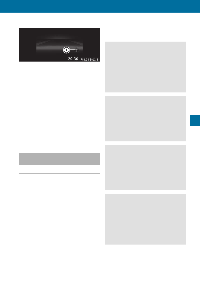
Information in the multifunction display
If Active Steering Assist is activated but not
ready for a steering intervention, steering wheel
symbol : appears in gray. If the system pro-
vides you with support by means of steering
interventions, symbol : is shown in green.
Deactivating Active Steering Assist
X
Deactivate the Active Distance Assist
DISTRONIC with Active Steering Assist func-
tion using the on-board computer
(Y page 237).
The Active Steering Assist OffActive Steering Assist Off mes-
sage appears on the multifunction display.
Active Steering Assist is deactivated.
When Active Distance Assist DISTRONIC is
deactivated or not available, Active Steering
Assist is deactivated automatically.
Level control (vehicles with the Off-
Road Engineering package)
Important safety notes
Level control adapts the vehicle level automati-
cally to the current operating and driving situa-
tion. This results in reduced fuel consumption
and improved handling.
Make changes to the vehicle level while the
vehicle is in motion. This enables the vehicle to
adjust to the new level as quickly as possible.
The vehicle level may change visibly if you park
the vehicle and the outside temperature
changes. If the temperature drops, the vehicle
level is lower; with an increase in temperature,
the vehicle level rises.
If you unlock the vehicle or open a door, the
vehicle begins to compensate for load discrep-
ancies while still parked. However, for signifi-
cant level changes, such as after the vehicle has
been stationary for a long period, the engine
must be on. For safety reasons, the vehicle is
only lowered when the doors are closed. Low-
ering is interrupted if a door is opened, and it
continues once the door has been closed.
Further information about "Driving off-road"
(Y page 165).
G
WARNING
When the vehicle is being lowered, people
could become trapped if their limbs are
between the vehicle body and the wheels or
underneath the vehicle. There is a risk of
injury.
Make sure no one is underneath the vehicle or
in the immediate vicinity of the wheel arches
when the vehicle is being lowered.
G
WARNING
When you drive with the vehicle raised, the
driving characteristics could be impaired by
the vehicle's raised center of gravity. The vehi-
cle could rollover more easily, for example on
a bend. There is a risk of an accident.
Always select as low a vehicle level as possi-
ble and adjust your driving style.
G
WARNING
When you drive with the chassis lowered or
raised, the vehicle's braking and driving char-
acteristics can be significantly impaired. You
could also exceed the permissible vehicle
height if the chassis is raised. There is a risk of
an accident.
Adjust the vehicle level before pulling away.
G
WARNING
Due to the high center of gravity, the vehicle
may start to skid and roll over in the event of
an abrupt steering maneuver and/or when
the vehicle's speed is not adapted to the road
conditions. There is a risk of an accident.
Always adapt your speed and driving style to
the vehicle's driving characteristics and to the
prevailing road and weather conditions.
!
When driving on extremely rough terrain,
select a high vehicle level in good time. Make
sure there is always sufficient ground clear-
ance. You will otherwise damage the vehicle.
Driving systems
179
Driving and parking
Z
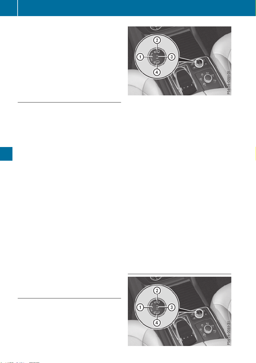
R
Utility vehicles have a significantly higher roll-
over rate than other types of vehicles.
Failure to operate this vehicle safely may
result in an accident, rollover of the vehicle,
and severe or fatal injury.
R
In a rollover crash, an unbelted person is sig-
nificantly more likely to die than a person
wearing a seat belt.
You and all vehicle occupants should always
wear your seat belts.
Basic settings
The extent to which the vehicle is raised or low-
ered depends on the basic setting selected.
Select:
R
the Comfort or Sport drive program for driv-
ing on normal roads
R
the Offroad drive program for driving on eas-
ily negotiable off-road terrain
R
the Offroad Plus drive program for off-road
driving
R
offroad level 1 for driving on easily negotiable
off-road terrain
R
offroad level 2 for driving on normal off-road
terrain
R
offroad level 3 for freeing the vehicle in par-
ticularly rough terrain at low speeds only
The individual vehicle levels differ from the nor-
mal level as follows:
R
–0.6 in (–15 mm) in the Sport drive program
R
+/–0 in (+/–0 mm) in the Comfort drive pro-
gram
R
+ 1.2 in (+ 30 mm) in the Offroad drive pro-
gram
R
+ 2.4 in (+ 60 mm) in the Offroad Plus drive
program
R
+ 1.2 in (+ 30 mm) in offroad level 1
R
+ 2.4 in (+ 60 mm) in offroad level 2
R
+ 3.5 in (+ 90 mm) in offroad level 3
Setting the vehicle level
!
Make sure that there is enough ground
clearance when the vehicle is being lowered.
It could otherwise hit the ground, damaging
the underbody.
Set the vehicle level using the selector wheel.
X
Start the engine.
X
Press selector wheel :.
Selector wheel : extends.
X
To raise the vehicle: turn selector wheel :
clockwise ;.
The vehicle is raised.
X
To lower the vehicle: turn selector wheel :
counter-clockwise ?.
The vehicle is lowered.
During the adjustment, the LoweringLowering or Vehi‐Vehi‐
clecle RisingRising message appears in the multifunc-
tion display.
If you press the % or a button on the
multifunction steering wheel, the message will
disappear. Once normal level has been reached,
all indicator lamps = go out.
The vehicle automatically selects normal level if
you:
R
drive at speeds above 70 mph (112 km/h) or
R
drive at speeds between 65 mph (105 km/h)
and 70 mph (112 km/h) for approximately
20 seconds
The vehicle is lowered to low level if you are
traveling at higher speeds.
Normal level
180
Driving systems
Driving and parking
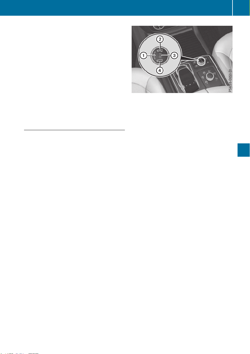
Setting the vehicle to normal level:
X
Start the engine.
X
Press selector wheel :.
Selector wheel : extends.
X
To lower the vehicle: turn selector wheel :
counter-clockwise ?.
The vehicle is lowered.
If one or more indicator lamps = are on:
X
Turn selector wheel : counter-clockwise ?
until all indicator lamps = that are lit start to
flash.
The vehicle is lowered to normal level. As
soon as the next lowest level is reached, the
indicator lamp stops flashing and goes out.
Offroad levels
General notes
Only select an offroad level when this is appro-
priate for road conditions. Otherwise, fuel con-
sumption increases and handling may be affec-
ted.
You can select from the following:
R
Offroad level 1 at speeds up to 60 mph
(96 km/h)
R
Offroad level 2 at speeds up to 40 mph
(64 km/h)
R
Offroad level 3 at speeds up to 12 mph
(20 km/h)
If you select an offroad level when driving at too
high a speed, the DriveDrive MoreMore SlowlySlowly message
appears in the multifunction display.
Offroad level 3 is only suitable for driving on
extremely difficult off-road terrain under partic-
ularly rough conditions.
R
Adjust your driving style to the altered han-
dling characteristics.
R
Do not drive at speeds above 12 mph
(20 km/h).
Indicator lamps = for the desired offroad level
flash:
R
the lower indicator lamp flashes, offroad
level 1 is selected
R
the lower and center indicator lamps flash,
offroad level 2 is selected
R
all three indicator lamps flash, offroad level 3
is selected
The vehicle adjusts to the offroad level selected.
As soon as an offroad level is reached, the cor-
responding indicator lamp stops flashing and
lights up constantly.
Raising the vehicle
Set the vehicle level using the selector wheel.
X
To raise the vehicle: turn selector wheel :
clockwise ;.
The vehicle is raised to offroad level 1 by 1.2 in
(30 mm) compared to the normal level.
During the adjustment, the Vehicle risingVehicle rising
message, for example, appears in the multifunc-
tion display.
If you press the % or a button on the
multifunction steering wheel, the message will
disappear.
i
Up to offroad level 2, you can hide the mes-
sages using the % or a button on the
multifunction steering wheel.
While the adjustment from offroad level 2 to off-
road level 3 is taking place, you will see a mes-
sage such as the following in the multifunction
display: Vehicle rising Max. speedVehicle rising Max. speed
12 mph (20 km/h)12 mph (20 km/h).
The Max.Max. speedspeed 12 mph12 mph (20 km/h)(20 km/h) message
draws your attention to the maximum speed
permitted for offroad level 3.
If you drive above 12 mph (20 km/h) at offroad
level 3, you will see the following message
Driving systems
181
Driving and parking
Z

shown in red in the multifunction display: Low‐Low‐
ering Max. speed 12 mph (20 km/h)ering Max. speed 12 mph (20 km/h).
i
You cannot clear these messages.
You also hear a warning. The vehicle is lowered
and offroad level 3 is canceled.
If you continue to increase your speed, the red
message continues to be shown in the multi-
function display. The newly set level is not dis-
played until the vehicle has been set to a level
suitable for the current speed.
Lowering the vehicle
If you drive faster than 12 mph (20 km/h) while
the vehicle level is being lowered, you will see
the following message shown in white in the
multifunction display: Lowering Max. speedLowering Max. speed
20 km/h20 km/h.
The vehicle is lowered to offroad level 2.
You will see a message in the multifunction dis-
play, for example: LoweringLowering.
Offroad level 2 is canceled and the vehicle is
lowered to offroad level 1 if you:
R
drive at speeds above 50 mph (80 km/h) or
R
drive at speeds between 40 mph (64 km/h)
and 50 mph (80 km/h) for longer than
20 seconds
Offroad level 1 is canceled. Depending on the
vehicle's speed and the selected drive program,
the vehicle is automatically lowered to normal
level or low level if you:
R
drive at speeds above 70 mph (112 km/h) or
R
drive at speeds between 65 mph (105 km/h)
and 70 mph (112 km/h) for longer than
20 seconds
HOLD function
General notes
The HOLD function can assist the driver in the
following situations:
R
when pulling away, especially on steep slopes
R
when maneuvering on steep slopes
R
when waiting in traffic
The vehicle is kept stationary without the driver
having to depress the brake pedal.
The braking effect is canceled and the HOLD
function deactivated when you depress the
accelerator pedal to pull away.
i
Do not use the HOLD function when driving
off-road, on steep uphill or downhill gradients
or on slippery or loose surfaces. The HOLD
function cannot hold the vehicle on such sur-
faces.
Important safety notes
G
WARNING
If the vehicle is only braked using the HOLD
function, the vehicle may roll away in the fol-
lowing situations when you leave the vehicle:
R
if there is a malfunction in the system or in
the voltage supply
R
if the HOLD function is deactivated by
depressing the accelerator pedal or brake
pedal, e.g. by a vehicle occupant
R
if the electrical system in the engine com-
partment, the battery or the fuses are tam-
pered with or the battery is disconnected
There is a risk of an accident.
Always deactivate the HOLD function and
secure the vehicle against rolling away before
you leave it.
!
When Active Distance Assist DISTRONIC or
the HOLD function is activated, the vehicle
brakes automatically in certain situations.
To avoid damage to the vehicle, deactivate
Active Distance Assist DISTRONIC and the
HOLD function in the following or similar sit-
uations:
R
when towing the vehicle
R
in the car wash
Deactivate the HOLD function (Y page 183).
Activation conditions
You can activate the HOLD function if:
R
the vehicle is stationary
R
the engine is running or if it has been auto-
matically switched off by the ECO start/stop
function
R
the driver's door is closed or your seat belt is
fastened
R
the electric parking brake is released
182
Driving systems
Driving and parking
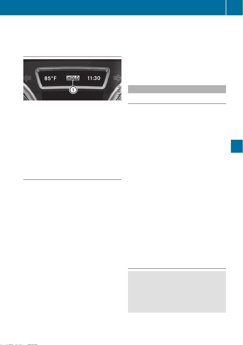
R
the transmission is in position h, k or i
R
Active Distance Assist DISTRONIC is deacti-
vated
Activating the HOLD function
X
Make sure that the activation conditions are
met.
X
Depress the brake pedal.
X
Quickly depress the brake pedal further
until : appears in the multifunction display.
The HOLD function is activated. You can
release the brake pedal.
i
If depressing the brake pedal the first time
does not activate the HOLD function, wait
briefly and then try again.
Deactivating the HOLD function
The HOLD function is deactivated automatically
if:
R
you depress the accelerator and the trans-
mission is in position h or k
R
you shift the transmission to position j
R
you depress the brake pedal again with a cer-
tain amount of pressure until : disappears
from the multifunction display
R
you secure the vehicle using the electric park-
ing brake
R
you activate Active Distance Assist
DISTRONIC
i
After a time, the electric parking brake
secures the vehicle and relieves the service
brake.
When the HOLD function is activated, the trans-
mission is automatically shifted to position j
if:
R
the driver's door is open and the driver's seat
belt is unfastened
R
the engine is switched off, unless it is auto-
matically switched off by the ECO start/stop
function
The electric parking brake secures the vehicle
automatically if the HOLD function is activated
when the vehicle is stationary and:
R
a system malfunction occurs
R
the power supply is insufficient
On steep uphill or downhill gradients or if there
is a malfunction, the transmission may also be
automatically shifted to position j.
AIRMATIC package
General notes
AIRMATIC is an air suspension system with var-
iable damping for improved driving comfort.
Level control ensures the best possible suspen-
sion and constant ground clearance, even with a
laden vehicle. When you drive fast, the vehicle is
lowered automatically to improve driving safety
and to reduce fuel consumption. There is also
the option to manually adjust the vehicle level.
AIRMATIC consists of:
R
level settings
R
level control and
R
ADS or ADS PLUS (Adaptive Damping Sys-
tem)
All vehicles (except Mercedes-AMG vehi-
cles): your vehicle may also be equipped with
the ACTIVE CURVE SYSTEM (Y page 185).
Mercedes-AMG vehicles: your vehicle is equip-
ped with the ACTIVE CURVE SYSTEM
(Y page 185).
Observe the notes on driving with a trailer
(Y page 221).
The vehicle level can be set using the DYNAMIC
SELECT controller (Y page 142)or the level but-
ton (Y page 185). The setting always corre-
sponds to the last selected function.
Important safety notes
G
WARNING
When the vehicle is being lowered, people
could become trapped if their limbs are
between the vehicle body and the wheels or
underneath the vehicle. There is a risk of
injury.
Driving systems
183
Driving and parking
Z
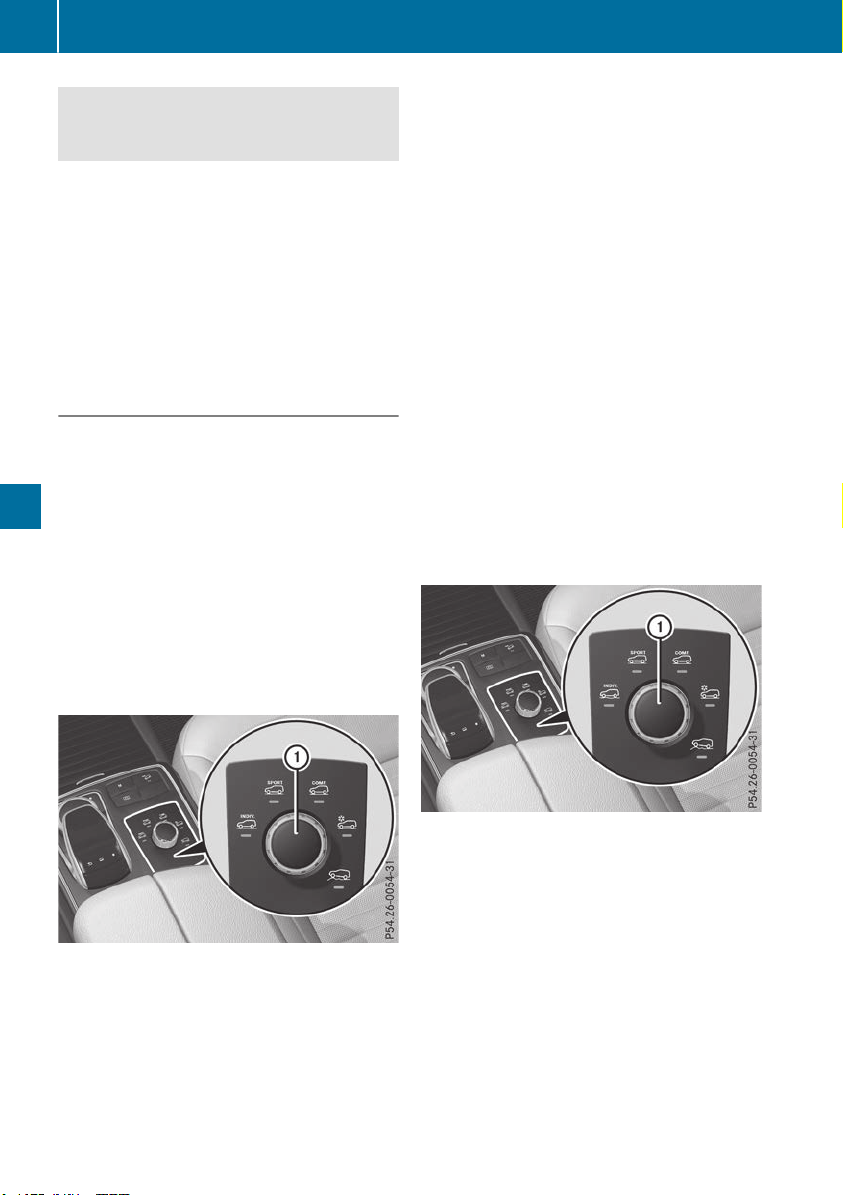
Make sure no one is underneath the vehicle or
in the immediate vicinity of the wheel arches
when the vehicle is being lowered.
If you unlock the vehicle or open a door, the
vehicle begins to compensate for load discrep-
ancies while still parked. However, for signifi-
cant level changes, such as after the vehicle has
been stationary for a long period, the engine
must be on. For safety reasons, the vehicle is
only lowered when the doors are closed. Low-
ering is interrupted if a door is opened, and it
continues once the door has been closed.
ADS and ADS PLUS (Adaptive Damping
System)
General notes
The Adaptive Damping System automatically
controls the calibration of the dampers. The
damping characteristics adapt to the current
operating and driving situation.
The damping is tuned individually to each wheel
and depends on:
R
your driving style, e.g. sporty
R
the road surface conditions
R
the drive program selected
R
the vehicle level setting
Selecting Comfort mode
In the Comfort drive program, the driving char-
acteristics of your vehicle are more comforta-
ble. Therefore, select this mode if you favor a
more comfortable driving style. Also select the
Comfort drive program when driving fast on
straight roads, e.g. on straight stretches of high-
way.
X
Select the Comfort drive program using
DYNAMIC SELECT controller :.
The vehicle is adjusted to normal level
All vehicles (except Mercedes-AMG vehi-
cles): in the Comfort drive program, the vehicle
is lowered by 0.6 in (15 mm) if you:
R
drive at speeds above 70 mph (112 km/h) or
R
drive at speeds between 60 mph (96 km/h)
and 70 mph (112 km/h) for longer than
20 seconds
The vehicle is raised again if you:
R
drive at speeds below 25 mph (40 km/h) or
R
drive at speeds between 25 mph (40 km/h)
and 40 mph (64 km/h) for longer than 20 sec-
onds
Mercedes-AMG vehicles: in the Comfort drive
program, the vehicle is:
R
lowered by 0.4 in (10 mm) if you drive at
speeds above 112 mph (180 km/h)
R
raised again if you drive at speeds below
87 mph (140 km/h)
Selecting Sport mode
The firmer setting of the suspension tuning in
the Sport drive program ensures even better
contact with the road. Select this drive program
when employing a sporty driving style, e.g. on
winding country roads.
DSR is not available in the Sport drive program.
For further information on DSR, see
(Y page 214).
X
Select the Sport drive program using
DYNAMIC SELECT controller :.
All vehicles (except Mercedes-AMG vehi-
cles): the vehicle is lowered by 0.6 in (15 mm)
compared to the normal level.
Mercedes-AMG vehicles: the vehicle
remains at the normal level.
184
Driving systems
Driving and parking
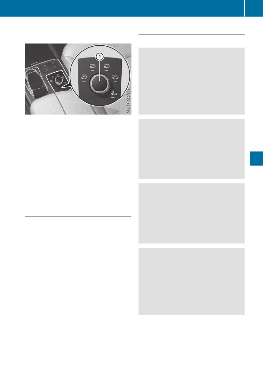
Selecting Sport Plus tuning (Mercedes-
AMG vehicles)
The very firm setting of the suspension setting in
the Sport Plus drive program ensures the best
possible contact with the road. Select this drive
program when employing a sporty driving style,
e.g. on winding country roads or primarily when
driving on race circuits.
DSR is not available in the Sport Plus drive pro-
gram. For further information on DSR, see
(Y page 214).
X
Select the Sport Plus drive program using
DYNAMIC SELECT controller :.
The vehicle is lowered by 0.4 in (10 mm) com-
pared to the normal level.
ACTIVE CURVE SYSTEM
The ACTIVE CURVE SYSTEM uses active stabil-
izers to optimize both driving comfort and vehi-
cle dynamics. Depending on the drive program
selected (Y page 146), the ACTIVE CURVE SYS-
TEM also changes the setting.
If you have selected the Comfort drive program:
R
rolling movement is reduced in the event of
changing surface undulations
R
the roll angle when cornering is reduced
R
the driving is dynamic
If you have selected the Sport drive program:
R
the roll angle is reduced significantly
R
the driving is even more dynamic
Mercedes-AMG vehicles: if you have selected
the Sport Plus drive program:
R
the roll angle is reduced even more signifi-
cantly
R
the driving is designed for maximum dyna-
mism
Vehicle level
Important safety notes
G
WARNING
When the vehicle is being lowered, people
could become trapped if their limbs are
between the vehicle body and the wheels or
underneath the vehicle. There is a risk of
injury.
Make sure no one is underneath the vehicle or
in the immediate vicinity of the wheel arches
when the vehicle is being lowered.
G
WARNING
When you drive with the vehicle raised, the
driving characteristics could be impaired by
the vehicle's raised center of gravity. The vehi-
cle could rollover more easily, for example on
a bend. There is a risk of an accident.
Always select as low a vehicle level as possi-
ble and adjust your driving style.
G
WARNING
When you drive with the chassis lowered or
raised, the vehicle's braking and driving char-
acteristics can be significantly impaired. You
could also exceed the permissible vehicle
height if the chassis is raised. There is a risk of
an accident.
Adjust the vehicle level before pulling away.
G
WARNING
Due to the high center of gravity, the vehicle
may start to skid and roll over in the event of
an abrupt steering maneuver and/or when
the vehicle's speed is not adapted to the road
conditions. There is a risk of an accident.
Always adapt your speed and driving style to
the vehicle's driving characteristics and to the
prevailing road and weather conditions.
!
When driving on extremely rough terrain,
select a high vehicle level in good time. Make
sure there is always sufficient ground clear-
ance. You will otherwise damage the vehicle.
R
Utility vehicles have a significantly higher roll-
over rate than other types of vehicles.
Driving systems
185
Driving and parking
Z

Failure to operate this vehicle safely may
result in an accident, rollover of the vehicle,
and severe or fatal injury.
R
In a rollover crash, an unbelted person is sig-
nificantly more likely to die than a person
wearing a seat belt.
You and all vehicle occupants should always
wear your seat belts.
General notes
Only select raised level if this is appropriate for
the road conditions. Otherwise, fuel consump-
tion may increase and handling may be affected.
Make changes to the vehicle level while the
vehicle is in motion. This enables the vehicle to
adjust to the new level as quickly as possible.
The vehicle level may change visibly if you park
the vehicle and the outside temperature
changes. If the temperature drops, the vehicle
level is lower; with an increase in temperature,
the vehicle level rises.
If you unlock the vehicle or open a door, the
vehicle begins to compensate for load discrep-
ancies while still parked. However, for signifi-
cant level changes, such as after the vehicle has
been stationary for a long period, the engine
must be on. For safety reasons, the vehicle is
only lowered when the doors are closed. Low-
ering is interrupted if a door is opened, and it
continues once the door has been closed.
Vehicles with no trailer coupled: below a
speed of 40 mph (64 km/h) you can choose
between the normal and raised vehicle level.
Select the normal vehicle level for normal road
surfaces and the raised vehicle level for driving
with snow chains or on particularly poor road
surfaces. Your selection remains stored even if
you remove the SmartKey from the ignition lock.
If you try to select raised level at a speed above
40 mph (64 km/h), the Drive More SlowlyDrive More Slowly
message appears in the multifunction display.
Vehicles with a trailer coupled: below a speed
of 19 mph (30 km/h), you can choose between
the normal and raised vehicle level.
Setting the raised vehicle level
X
Start the engine.
If indicator lamp ; is not lit:
X
Press button :.
Indicator lamp ; flashes while the vehicle is
being raised, and lights up continuously as
soon as the vehicle reaches the desired level.
All vehicles (except Mercedes-AMG vehi-
cles): the vehicle is raised by 2.4 in (60 mm)
compared to the normal level.
Mercedes-AMG vehicles: the vehicle is
raised by 2 in (50 mm) compared to the nor-
mal level.
The Vehicle RisingVehicle Rising message appears in the
multifunction display.
The message remains until the raised level is
reached.
If you press the % or a button on the
multifunction steering wheel, the message will
disappear.
The raised vehicle level setting is canceled in the
following cases:
R
All vehicles (except Mercedes-AMG vehi-
cles): you are driving faster than 50 mph
(80 km/h).
R
Mercedes-AMG vehicles: you are driving
faster than 43 mph (70 km/h).
R
All vehicles (except Mercedes-AMG vehi-
cles): you drive for approximately 20 seconds
between 40 mph (64 km/h) and 50 mph
(80 km/h).
R
Mercedes-AMG vehicles: you drive at
speeds between 40 mph (64 km/h) and
43 mph (70 km/h) for approximately 20 sec-
onds.
R
You drive with a trailer at speeds greater than
19 mph (30 km/h).
186
Driving systems
Driving and parking
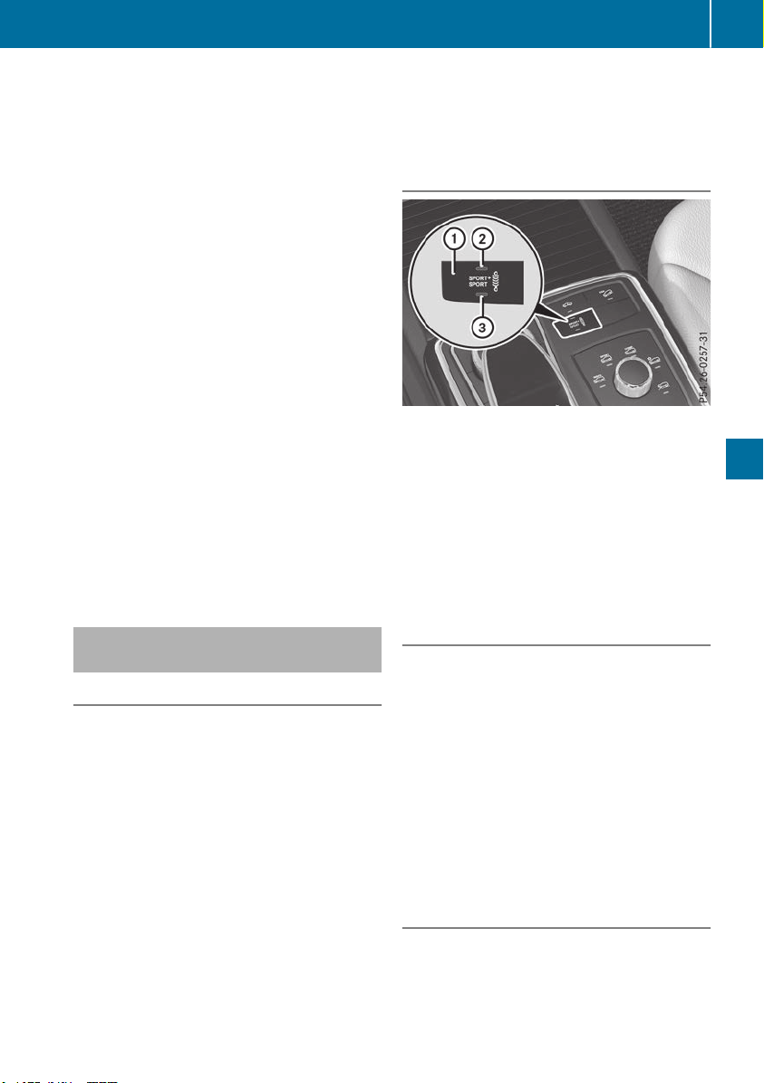
The raised vehicle level remains saved when you
are not driving within these speed ranges.
Setting the normal vehicle level
!
Make sure that there is enough ground
clearance when the vehicle is being lowered.
It could otherwise hit the ground, damaging
the underbody.
X
Start the engine.
If indicator lamp ; is lit:
X
Press button :.
Indicator lamp ; flashes while the vehicle is
being lowered, and goes out as soon as the
desired vehicle level is reached.
Vehicles with no trailer coupled: the vehi-
cle is adjusted to the height of the selected
drive program (Y page 142).
Vehicles with a trailer coupled: the vehicle
is adjusted to normal level regardless of the
drive program selected (Y page 142). The
vehicle remains at the normal level, even if the
drive program is changed.
During the adjustment, the LoweringLowering mes-
sage appears in the multifunction display.
If you press the % or a button on the
multifunction steering wheel, the message will
disappear.
AMG adaptive sport suspension sys-
tem
General notes
i
The AMG adaptive sport suspension system
is available for Mercedes-AMG vehicles and
for the Mercedes-AMG GLE 43 4MATIC.
The electronically controlled damping system
works continuously. This improves driving
safety and ride comfort.
The damping is tuned individually to each wheel
and depends on:
R
your driving style, e.g. sporty
R
the road surface condition, e.g. bumps
R
your individual selection of Sport, Sport+ or
Comfort
The suspension setting can be adjusted using
button : in the center console or the DYNAMIC
SELECT controller (Y page 142).
Each time you start the engine with the ignition
SmartKey or the Start/Stop button, Comfort
mode is activated. For further information about
starting the engine, see (Y page 136).
Sport mode
The firmer setting of the suspension tuning in
Sport mode ensures even better contact with
the road. Select this mode when employing a
sporty driving style, e.g. on winding country
roads.
X
Press button : repeatedly until indicator
lamp = lights up.
You have selected Sport mode.
The AMG Suspension System SPORTAMG Suspension System SPORT mes-
sage appears in the multifunction display.
Sport + mode
The very firm setting of the suspension setting in
Sport + mode ensures the best possible contact
with the road. Select this mode only when driv-
ing on race circuits.
If indicator lamps ; and = are off:
X
Press button : repeatedly until indicator
lamp ; lights up.
You have selected Sport + mode.
The AMGAMG SuspensionSuspension SystemSystem SPORT +SPORT + mes-
sage appears in the multifunction display.
In "Sport +" mode, the vehicle is lowered by
10 mm compared to the normal level.
Comfort mode
In Comfort mode, the driving characteristics of
your vehicle are more comfortable. Select this
mode if you favor a more comfortable driving
style, but also when driving fast on straight
roads, e.g. highways.
Driving systems
187
Driving and parking
Z
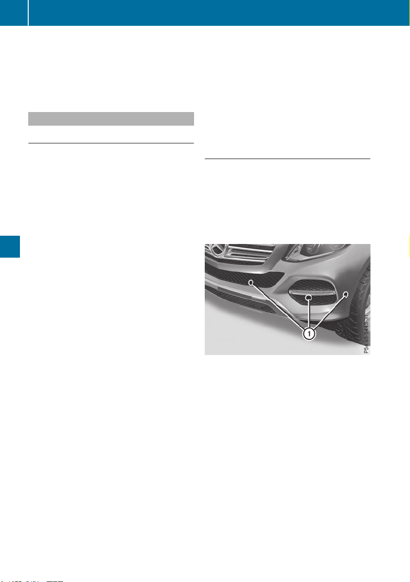
X
Press button : repeatedly until indicator
lamps ; and = go out.
You have selected Comfort mode.
The AMGAMG SuspensionSuspension SystemSystem COMFORTCOMFORT mes-
sage appears in the multifunction display.
Parking Assist PARKTRONIC
Important safety notes
Parking Assist PARKTRONIC is an electronic
parking aid with ultrasound. It monitors the area
around your vehicle using six sensors in the
front bumper and six sensors in the rear
bumper. Parking Assist PARKTRONIC visually
and audibly indicates the distance between your
vehicle and an object.
Parking Assist PARKTRONIC is only an aid. It is
not a replacement for your attention to your
immediate surroundings. You are always
responsible for safe maneuvering, parking and
exiting a parking space. Make sure that there
are no persons, animals or objects in the maneu-
vering area while maneuvering and parking in/
leaving parking spaces.
!
When parking, pay particular attention to
objects above or below the sensors, such as
flower pots or trailer drawbars. PARKTRONIC
does not detect such objects when they are in
the immediate vicinity of the vehicle. You
could damage the vehicle or the objects.
The sensors may not detect snow and other
objects that absorb ultrasonic waves.
Ultrasonic sources such as an automatic car
wash, the compressed-air brakes on a truck
or a pneumatic drill could cause PARKTRONIC
to malfunction.
PARKTRONIC may not function correctly on
uneven terrain.
!
Fold in the ball coupling if the trailer tow
hitch is not required. PARKTRONIC measures
the minimum detection range to an obstacle
from the bumper, not the ball coupling.
Parking Assist PARKTRONIC is deactivated for
the rear area when you establish an electrical
connection between your vehicle and a trailer.
Parking Assist PARKTRONIC is activated auto-
matically when you:
R
switch on the ignition
R
shift the transmission to position h, k or
i
R
release the electric parking brake.
Parking Assist PARKTRONIC is deactivated at
speeds above 11 mph (18 km/h). It is reactiva-
ted at lower speeds.
Range of the sensors
General notes
Parking Assist PARKTRONIC does not take into
account obstacles located:
R
below the detection range, such as persons,
animals or objects
R
above the detection range, such as overhang-
ing loads, truck overhangs or loading ramps
:
Sensors in the front bumper, left-hand side
(example)
The sensors must be free from dirt, ice or slush.
They can otherwise not function correctly. Clean
the sensors regularly, taking care not to scratch
or damage them (Y page 330).
188
Driving systems
Driving and parking
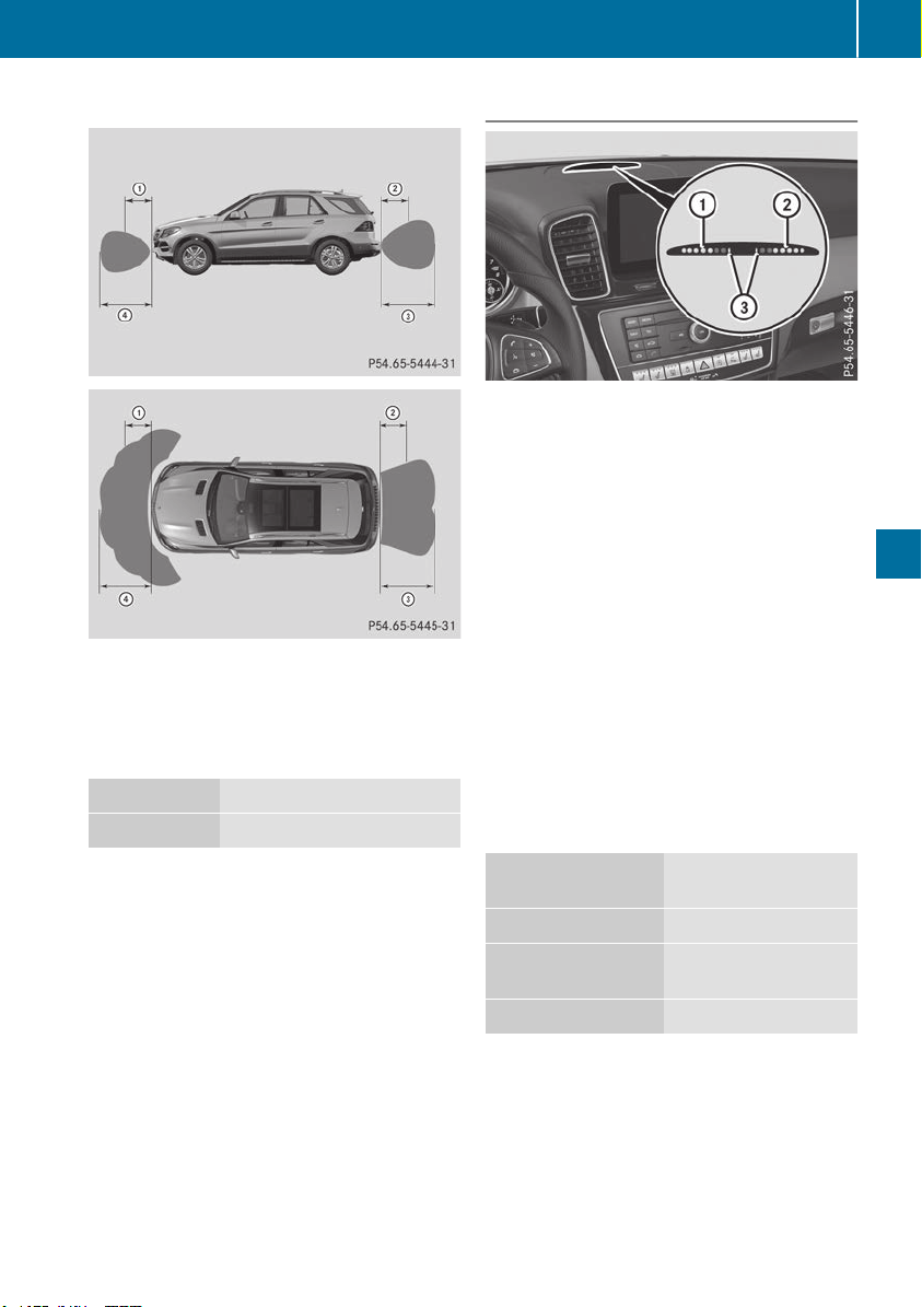
Range
:
Approx. 24 in (approx. 60 cm) (corners)
;
Approx. 32 in (approx. 80 cm) (corners)
=
Approx. 48 in (approx. 120 cm) (center)
?
Approx. 40 in (approx. 100 cm) (center)
Minimum distance
Center Approx. 8 in (approx. 20 cm)
Corners Approx. 6 in (approx. 15 cm)
If there is an obstacle within this range, the rel-
evant warning displays light up and a warning
tone sounds. If the distance falls below the min-
imum, the distance may no longer be shown.
Warning displays
:
Segments on the left-hand side of the vehi-
cle
;
Segments on the right-hand side of the vehi-
cle
=
Segments showing operational readiness
The warning displays show the distance
between the sensors and the obstacle. The
warning display for the front area is located on
the dashboard above the center air vents. The
warning display for the rear area is located on
the headliner in the rear passenger compart-
ment.
The warning display for each side of the vehicle
is divided into five yellow and two red segments.
Parking Assist PARKTRONIC is operational if yel-
low segments showing operational readiness =
light up.
The selected transmission position and the
direction in which the vehicle is rolling deter-
mine which warning display is active when the
engine is running.
Transmission posi-
tion
Warning display
h
Front area activated
k, i or the vehicle
is rolling backwards
Rear and front areas
activated
j
No areas activated
One or more segments light up as the vehicle
approaches an obstacle, depending on the vehi-
cle's distance from the obstacle.
Driving systems
189
Driving and parking
Z
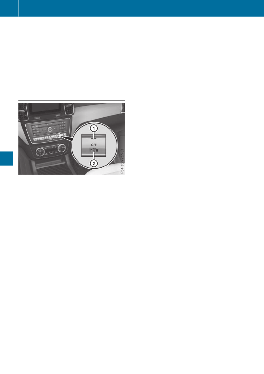
From the:
R
sixth segment onwards, you will hear an inter-
mittent warning tone for approximately two
seconds.
R
seventh segment onwards, you will hear a
warning tone for approximately two seconds.
This indicates that you have now reached the
minimum distance.
Deactivates or activates Parking Assist
PARKTRONIC
:
Indicator lamp
;
Deactivates or activates Parking Assist
PARKTRONIC
If indicator lamp : lights up, Parking Assist
PARKTRONIC is deactivated. Active Parking
Assist is then also deactivated.
i
Parking Assist PARKTRONIC is automati-
cally activated when you turn the SmartKey to
position 2 in the ignition lock.
190
Driving systems
Driving and parking

Problems with Parking Assist PARKTRONIC
Problem
Possible causes/consequences and MM Solutions
Only the red segments in
the Parking Assist
PARKTRONIC warning
displays are lit. You also
hear a warning tone for
approximately two sec-
onds.
Parking Assist
PARKTRONIC is deacti-
vated after approx-
imately five seconds,
and the indicator lamp in
the Parking Assist
PARKTRONIC button
lights up.
Parking Assist PARKTRONIC has malfunctioned and has been deacti-
vated.
X
If problems persist, have Parking Assist PARKTRONIC checked at a
qualified specialist workshop.
Only the red segments in
the Parking Assist
PARKTRONIC warning
displays are lit. Parking
Assist PARKTRONIC is
deactivated after
approximately five sec-
onds.
The Parking Assist PARKTRONIC sensors are dirty or there is inter-
ference.
X
Clean the Parking Assist PARKTRONIC sensors (Y page 330).
X
Switch the ignition back on.
The problem may be caused by an external source of radio or ultra-
sound waves.
X
Check to see if Parking Assist PARKTRONIC works at a different
location.
Active Parking Assist
General notes
Active Parking Assist is an electronic parking aid
with ultrasound. It measures the road on both
sides of the vehicle. A parking symbol indicates
a suitable parking space. Active steering inter-
vention and brake application can assist you
during parking. Parking Assist PARKTRONIC is
also available (Y page 188).
Important safety notes
Active Parking Assist is merely an aid. It is not a
replacement for your attention to your immedi-
ate surroundings. You are always responsible
for safe maneuvering, parking and exiting a
parking space. Make sure that no persons, ani-
mals or objects are in the path of your vehicle.
When Parking Assist PARKTRONIC is deactiva-
ted, Active Parking Assist is also unavailable.
G
WARNING
While parking or pulling out of a parking
space, the vehicle swings out and can drive
onto areas of the oncoming lane. This could
cause you to collide with other road users or
objects. There is a risk of an accident.
Pay attention to other road users or objects.
Stop the vehicle if necessary or cancel the
Active Parking Assist parking procedure.
!
If they cannot be avoided, drive over obsta-
cles such as curbs slowly and at an obtuse
angle. Otherwise, you may damage the
wheels or tires.
Active Parking Assist may also show parking
spaces that are not suitable for parking, e.g.:
R
where parking or stopping is prohibited
R
in front of driveways or entrances and exits
R
on unsuitable surfaces
Driving systems
191
Driving and parking
Z
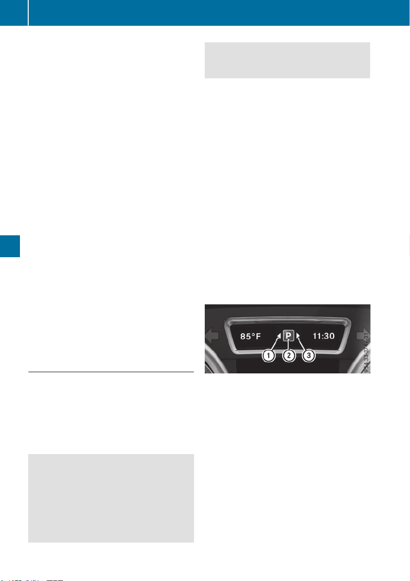
Parking tips:
R
on narrow roads, drive as close to the parking
space as possible
R
parking spaces that are littered or overgrown
might be identified or measured incorrectly
R
parking spaces that are partially occupied by
trailer drawbars might not be identified as
such or be measured incorrectly
R
snowfall or heavy rain may lead to a parking
space being measured inaccurately
R
pay attention to the warning messages of
Parking Assist PARKTRONIC during the park-
ing procedure (Y page 188).
R
you can intervene in the steering procedure to
correct it at any time. Active Parking Assist
will then be canceled
R
when transporting a load which protrudes
from your vehicle, you should not use Active
Parking Assist
R
never use Active Parking Assist when snow
chains are installed
R
make sure that the tire pressures are always
correct. This has a direct influence on the
parking characteristics of the vehicle
Use Active Parking Assist for parking spaces:
R
parallel or at right angles to the direction of
travel
R
on straight roads, not bends
R
on the same level as the road, e.g. not on the
pavement
Detecting parking spaces
Objects located above the detection range of
Active Parking Assist will not be detected when
the parking space is measured. These are not
taken into account when the parking/exiting
procedure is calculated, e.g. overhanging loads,
tail sections or loading ramps of trucks. Active
Parking Assist may therefore guide you into the
parking space too early.
G
WARNING
If there are objects above the detection range:
R
Active Parking Assist may steer too early
R
the vehicle may not stop in front of these
objects
This could cause a collision. There is a risk of
an accident.
If objects are located above the detection
range, stop and deactivate Active Parking
Assist.
Further information about the detection range
(Y page 188).
Active Parking Assist does not assist you park-
ing in spaces at right angles to the direction of
travel if:
R
two parking spaces are located directly next
to one another
R
the parking space is directly next to a low
obstacle such as a low curb
R
you park forwards
Active Parking Assist does not assist you park-
ing in spaces that are parallel or at right angles
to the direction of travel if:
R
the parking space is on a curb
R
the system reads the parking space as being
blocked, for example by foliage or grass pav-
ing blocks
R
the area is too small for the vehicle to maneu-
ver into
R
the parking space is bordered by an obstacle,
e.g. a tree, a post or a trailer
:
Detected parking space on the left
;
Parking symbol
=
Detected parking space on the right
Active Parking Assist is switched on automati-
cally when driving forwards. The system is
operational up to a speed of approximately
22 mph (35 km/h). While in operation, the sys-
tem independently locates and measures park-
ing spaces on both sides of the vehicle.
Active Parking Assist will only detect parking
spaces:
R
parallel or at right angles to the direction of
travel
R
that are parallel to the direction of travel and
at least 59 in (1.5 m) wide
192
Driving systems
Driving and parking

R
that are parallel to the direction of travel and
at least 39.5 in (1.0 m) longer than your vehi-
cle
R
that are at right angles to the direction of
travel and at least 39.5 in (1.0 m) wider than
your vehicle
i
Note that Active Parking Assist cannot
measure the size of a parking space if it is at
right angles to the direction of travel. You will
need to judge whether your vehicle will fit into
the parking space.
When driving at speeds below 19 mph
(30 km/h), you will see parking symbol ; as a
status indicator in the instrument cluster. When
a parking space has been detected, an arrow
towards the right or the left also appears. By
default, Active Parking Assist only displays park-
ing spaces on the front-passenger side. Parking
spaces on the driver's side are displayed as
soon as the turn signal on the driver's side is
activated. When parking on the driver's side,
this must remain activated until you confirm the
use of Active Parking Assist by pressing the
a button on the multifunction steering
wheel. The system automatically determines
whether the parking space is parallel or at right
angles to the direction of travel.
A parking space is displayed while you are driv-
ing past it, and until you are approximately 50 ft
(15 m) away from it.
Parking
G
WARNING
If you leave the driver's seat when the vehicle
is being braked only by the Active Parking
Assist, it could roll away in the following sit-
uations:
R
if there is a malfunction in the system or in
the voltage supply
R
if the electrical system in the engine com-
partment, the battery or the fuses have
been tampered with
R
if the battery is disconnected
R
if the vehicle is accelerated, e.g. by a vehi-
cle occupant
There is a risk of an accident.
Before leaving the vehicle, always secure it
against rolling away.
i
If Parking Assist PARKTRONIC detects
obstacles, Active Parking Assist will brake
automatically whilst the vehicle is parking.
You are responsible for braking in good time.
X
Stop the vehicle when the parking space sym-
bol shows the desired parking space in the
instrument cluster.
X
Shift the transmission to position k.
The StartStart ParkingParking Assist?Assist? Yes:Yes: OKOK No:No:
% message will appear on the multifunc-
tion display.
X
To cancel the procedure: press the %
button on the multifunction steering wheel or
pull away.
or
X
To park using Active Parking Assist: press
the a button on the multifunction steering
wheel.
The ParkingParking AssistAssist ActiveActive AccelerateAccelerate
and Brake Observe Surroundingsand Brake Observe Surroundings mes-
sage will appear on the multifunction display.
X
Let go of the multifunction steering wheel.
X
Back up the vehicle, being ready to brake at all
times. When backing up, drive at a speed
below approximately 6 mph (10 km/h). Oth-
erwise, Active Parking Assist will be canceled.
Active Parking Assist brakes the vehicle to a
standstill when the vehicle approaches the
rear border of the parking space.
Maneuvering may be required in tight parking
spaces.
The Parking Assist Active Select DParking Assist Active Select D
Observe SurroundingsObserve Surroundings message will appear
on the multifunction display.
X
Shift the transmission to position h while
the vehicle is stationary.
Active Parking Assist immediately steers in
the other direction.
The ParkingParking AssistAssist ActiveActive AccelerateAccelerate
and Brake Observe Surroundingsand Brake Observe Surroundings mes-
sage will appear on the multifunction display.
i
You will achieve the best results by waiting
for the steering procedure to complete before
pulling away.
X
Drive forwards and be ready to brake at all
times.
Active Parking Assist brakes the vehicle to a
standstill.
The Parking Assist Active Select RParking Assist Active Select R
Observe SurroundingsObserve Surroundings message will appear
on the multifunction display.
Driving systems
193
Driving and parking
Z

As soon as the parking procedure is complete,
the Active Parking Assist FinishedActive Parking Assist Finished mes-
sage will appear on the multifunction display
and you will hear a tone. The vehicle is now
parked. The vehicle is kept stationary without
the driver having to depress the brake pedal.
The braking effect is canceled when you depress
the accelerator pedal.
Active Parking Assist no longer supports you
with steering interventions and brake applica-
tions. When Active Parking Assist is finished,
you must steer and brake again yourself. Park-
ing Assist PARKTRONIC is still available.
Parking tips:
R
The way your vehicle is positioned in the park-
ing space after parking is dependent on vari-
ous factors. These include the position and
shape of the vehicles parked in front and
behind it and the conditions of the location. It
may be the case that Active Parking Assist
guides you too far into a parking space, or not
far enough into it. In some cases, it may also
lead you across or onto the curb. If necessary,
cancel the parking procedure with Active
Parking Assist.
R
You can also preselect transmission position
h. The vehicle redirects and does not drive
as far into the parking space. Should the
transmission change take place too early, the
parking procedure will be canceled. A sensi-
ble parking position can no longer be ach-
ieved from this position.
Exiting a parking space
In order that Active Parking Assist can support
you when exiting the parking space:
R
the border of the parking space must be high
enough at the front and the rear. A curb is too
small, for example.
R
the border of the parking space must not be
too wide. Your vehicle can be maneuvered
into a position at a maximum of 45° to the
starting position in the parking space.
R
a maneuvering distance of at least 3.3 ft
(1.0 m) must be available.
Active Parking Assist can only assist you with
exiting a parking space if you have parked the
vehicle parallel to the direction of travel using
Active Parking Assist.
i
If Parking Assist PARKTRONIC detects
obstacles, Active Parking Assist brakes auto-
matically whilst the vehicle is exiting the park-
ing space. You are responsible for braking in
good time.
X
Start the engine.
X
Release the electric parking brake.
X
Switch on the turn signal in the direction you
will drive out of the parking space.
X
Shift the transmission to position h or k.
The StartStart ParkingParking Assist?Assist? Yes:Yes: OKOK No:No:
% message will appear on the multifunc-
tion display.
X
To cancel the procedure: press the %
button on the multifunction steering wheel or
pull away.
or
X
To exit a parking space using Active Park-
ing Assist: press the a button on the mul-
tifunction steering wheel.
The ParkingParking AssistAssist ActiveActive AccelerateAccelerate
and Brake Observe Surroundingsand Brake Observe Surroundings mes-
sage will appear on the multifunction display.
X
Let go of the multifunction steering wheel.
X
Pull away, being ready to brake at all times. Do
not exceed a maximum speed of approx-
imately 6 mph (10 km/h) when exiting a park-
ing space. Otherwise, Active Parking Assist
will be canceled.
X
Depending on the message or as required,
shift the transmission to position h or k
when the vehicle is stationary.
Active Parking Assist immediately steers in
the other direction. The Parking AssistParking Assist
ActiveActive AccelerateAccelerate andand BrakeBrake ObserveObserve
SurroundingsSurroundings message will appear on the
multifunction display.
i
You will achieve the best results by waiting
for the steering procedure to complete before
pulling away.
If you back up after activation, the steering
wheel is moved to the straight-ahead posi-
tion.
X
Drive forwards and back up as prompted by
the Parking Assist PARKTRONIC warning dis-
plays, several times if necessary.
Once you have exited the parking space com-
pletely, the steering wheel is moved to the
straight-ahead position. You will hear a tone and
the Active Parking Assist FinishedActive Parking Assist Finished mes-
sage will appear on the multifunction display.
You will then have to steer and merge into traffic
on your own. Parking Assist PARKTRONIC is still
available. You can take over the steering before
194
Driving systems
Driving and parking
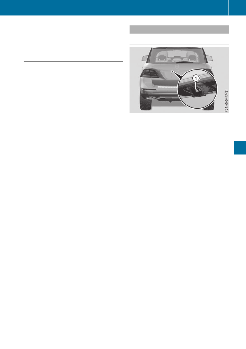
the vehicle has exited the parking space com-
pletely. This is useful, for example when you
recognize that it is already possible to pull out of
the parking space.
Canceling Active Parking Assist
X
Stop the movement of the multifunction
steering wheel or steer yourself.
Active Parking Assist will be canceled at once.
The Active Parking Assist CanceledActive Parking Assist Canceled
message appears on the multifunction dis-
play.
or
X
Press the Parking Assist PARKTRONIC button
(Y page 190).
Parking Assist PARKTRONIC is switched off
and Active Parking Assist is immediately can-
celed. The Active Parking Assist Can‐Active Parking Assist Can‐
celedceled message appears on the multifunction
display.
Active Parking Assist is canceled automatically
if:
R
the electric parking brake is engaged
R
transmission position j is selected
R
parking using Active Parking Assist is no lon-
ger possible
R
you are driving faster than 6 mph (10 km/h)
R
a wheel spins, ESP
®
intervenes or fails. The
÷ warning lamp lights up in the instrument
cluster
A warning tone sounds. The parking symbol dis-
appears and the multifunction display shows the
ActiveActive ParkingParking AssistAssist CanceledCanceled message.
When Active Parking Assist is canceled, you
must steer and brake again yourself.
If a system malfunction occurs, the vehicle is
braked to a standstill. To drive on, depress the
accelerator again.
Rear view camera
General notes
Rear view camera : is an optical parking and
maneuvering aid. It shows the area behind your
vehicle with guide lines in the multimedia sys-
tem.
The area behind the vehicle is displayed as a
mirror image, as in the rear view mirror.
i
The text shown in the multimedia system
display depends on the language setting. The
following are examples of rear view camera
displays in the multimedia system.
Important safety notes
The rear view camera is only an aid. It is not a
replacement for your attention to your immedi-
ate surroundings. You are always responsible
for safe maneuvering and parking. Make sure
that there are no persons, animals or objects in
the maneuvering area while maneuvering and
parking in parking spaces.
Under the following circumstances, the rear
view camera will not function, or will function in
a limited manner:
R
if the trunk lid is open
R
if there is heavy rain, snow or fog
R
at night or in very dark places
R
if the camera is exposed to very bright light
R
if the area is lit by fluorescent bulbs or LED
lighting (the display may flicker)
R
if there is a sudden change in temperature,
e.g. when driving into a heated garage in win-
ter
Driving systems
195
Driving and parking
Z
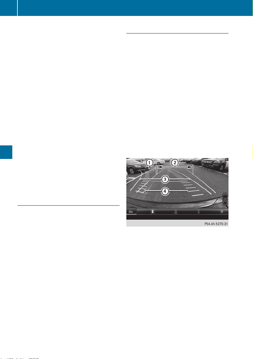
R
if the camera lens is dirty or obstructed.
Observe the notes on cleaning
(Y page 331)
R
if the rear of your vehicle is damaged. In this
event, have the camera position and setting
checked at a qualified specialist workshop
The field of vision and other functions of the rear
view camera may be restricted due to additional
accessories on the rear of the vehicle (e.g.
license plate holder, bicycle rack).
For technical reasons, leaving the standard
height can result in inaccuracies in the guide
lines on vehicles with a height-adjustable chas-
sis.
i
The rear view camera is protected from rain-
drops and dust by means of a flap. When the
rear view camera is activated, this flap opens.
The flap closes again when:
R
you have finished the maneuvering process
R
you switch off the engine
R
you open the cargo compartment
Observe the notes on cleaning (Y page 331).
For technical reasons, the flap may remain
open briefly after the rear view camera has
been deactivated.
Activating/deactivating the rear view
camera
X
To activate: make sure that the SmartKey is
in position 2 in the ignition lock.
X
Make sure that the Activation by R gearActivation by R gear
function is selected in the multimedia system
(see the Digital Operator's Manual).
X
Engage reverse gear.
The rear view camera flap opens. The multi-
media system shows the area behind the vehi-
cle with guide lines.
The image from the rear view camera is avail-
able throughout the maneuvering process.
X
To switch the function mode for vehicles
with trailer tow hitch: using the controller,
select symbol : for the "Reverse parking"
function or symbol ; for "Coupling up a
trailer".
The symbol of the selected function is high-
lighted.
To deactivate: the rear view camera deacti-
vates if you shift the transmission to j or after
driving forwards a short distance.
Displays in the multimedia system
The rear view camera may show a distorted view
of obstacles, show them incorrectly or not at all.
The rear view camera does not show objects in
the following positions:
R
very close to the rear bumper
R
under the rear bumper
R
in the area immediately above the tailgate
handle
!
Objects not at ground level may appear to
be further away than they actually are, e.g.:
R
the bumper of a parked vehicle
R
the drawbar of a trailer
R
the ball coupling of a trailer tow hitch
R
the rear section of an HGV
R
a slanted post
Use the guidelines only for orientation.
Approach objects no further than the bottom-
most guideline.
:
Yellow guide line at a distance of approx-
imately 13 ft (4.0 m) from the rear of the
vehicle
;
White guide line without turning the steering
wheel, vehicle width including the exterior
mirrors (static)
=
Yellow guide line for the vehicle width
including the exterior mirrors, for current
steering wheel angle (dynamic)
?
Yellow lane marking the course the tires will
take at the current steering wheel angle
(dynamic)
196
Driving systems
Driving and parking
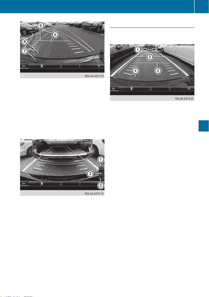
A
Yellow guide line at a distance of approx-
imately 3 ft (1.0 m) from the rear of the vehi-
cle
B
Vehicle center axle (marker assistance)
C
Bumper
D
Red guide line at a distance of approximately
12 in (0.30 m) from the rear of the vehicle
The guide lines are shown when the transmis-
sion is in position k.
The distance specifications only apply to
objects that are at ground level.
:
Front warning display
;
Additional measurement operational readi-
ness indicator for Parking Assist
PARKTRONIC
=
Rear warning display
Vehicles with Parking Assist PARKTRONIC:
when Parking Assist PARKTRONIC is opera-
tional (Y page 188), additional measurement
operational readiness indicator ; appears in
the multimedia system. If the Parking Assist
PARKTRONIC warning displays are active or
light up, warning displays : and = are also
active or light up correspondingly in the multi-
media system.
"Reverse parking" function
Backing up straight into a parking space
without steering input
:
White guide line without steering input –
vehicle width including the exterior mirrors
(static)
;
Yellow guide line for the vehicle width
including the exterior mirrors, for current
steering wheel angle (dynamic)
=
Yellow guide line at a distance of approx-
imately 3 ft (1.0 m) from the rear of the vehi-
cle
?
Red guide line at a distance of approximately
12 in (0.30 m) from the rear of the vehicle
X
Make sure that the rear view camera is
switched on (Y page 196).
The lane and the guide lines are shown.
X
With the help of white guide line :, check
whether the vehicle will fit into the parking
space.
X
Using white guide line : as a guide, carefully
back up until you reach the end position.
Red guide line ? is then at the end of the
parking space. The vehicle is almost parallel
in the parking space.
Driving systems
197
Driving and parking
Z
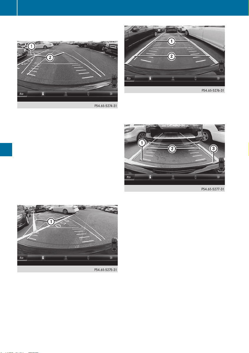
Reverse perpendicular parking with steer-
ing input
:
Parking space marking
;
Yellow guide line for the vehicle width
including the exterior mirrors, for current
steering wheel angle (dynamic)
X
Drive past the parking space and bring the
vehicle to a standstill.
X
Make sure that the rear view camera is
switched on (Y page 196).
The lane and the guide lines are shown.
X
While the vehicle is at a standstill, turn the
steering wheel in the direction of the parking
space until yellow guide line ; reaches park-
ing space marking :.
X
Maintain the steering input and reverse care-
fully.
:
Yellow guide line for the vehicle width
including the exterior mirrors, for current
steering wheel angle (dynamic)
X
Stop the vehicle when it is almost exactly in
front of the parking space.
The white lane should be as close to parallel
with the parking space marking as possible.
:
White guide line for current steering input
;
Parking space marking
X
Turn the steering wheel to the center position
while the vehicle is stationary.
:
Red guide line at a distance of approximately
12 in (0.30 m) from the rear of the vehicle
;
White guide line without steering input
=
End of parking space
X
Back up carefully until you have reached the
final position.
Red guide line : is then at end of parking
space =. The vehicle is almost parallel in the
parking space.
198
Driving systems
Driving and parking
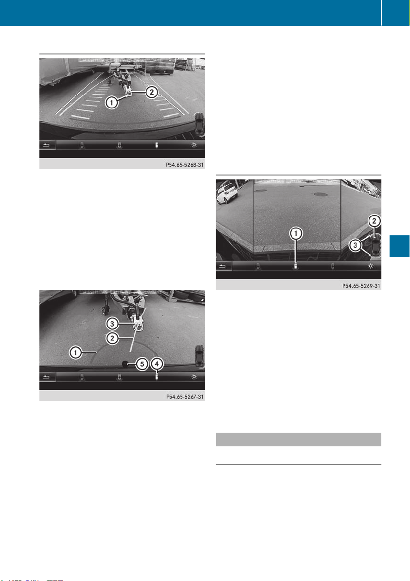
"Coupling up a trailer" function
:
Vehicle center point on the yellow guide line
at a distance of approximately 1.0 m from
the rear of the vehicle
;
Trailer drawbar
This function is only available on vehicles with a
trailer tow hitch.
X
Before coupling up a trailer, set the height of
trailer drawbar ; so that it is slightly higher
than the ball coupling.
X
Position the vehicle centrally in front of trailer
drawbar ;.
:
Red guide line at a distance of approximately
0.30 m from the ball coupling
;
Trailer drawbar marker assistant
=
Trailer drawbar
?
Symbol for the "Coupling up a trailer" func-
tion
A
Ball coupling
i
For technical reasons, the ball coupling of
the trailer tow hitch in the multimedia system
display is either only partially visible or not at
all.
X
Select symbol ? using the controller.
The "Coupling up a trailer" function is selec-
ted. The distance specifications now only
apply to objects that are at the same level as
the ball coupling.
X
Back up carefully, making sure that trailer
drawbar locating aid ; points approximately
in the direction of trailer drawbar =.
X
Back up carefully until trailer drawbar = rea-
ches the red guide line.
The distance between the trailer drawbar and
the red guide line is now approximately
0.30 m.
X
Couple up the trailer (Y page 221).
180° view
:
Symbol for the 180° view function
;
Your vehicle
=
Warning displays for Parking Assist
PARKTRONIC
You can also use the rear view camera to select
a 180° view.
When Parking Assist PARKTRONIC is opera-
tional (Y page 188), a symbol for your own vehi-
cle appears in the multimedia system. If the
Parking Assist PARKTRONIC warning displays
are active, warning displays = light up in the
multimedia system in yellow or red accordingly.
360° camera
General notes
The 360° camera is a system consisting of four
cameras.
The system processes images from the follow-
ing cameras:
R
Rear view camera
R
Front camera
R
Two cameras in the exterior rear view mirrors
Driving systems
199
Driving and parking
Z

The cameras cover the immediate surroundings
of the vehicle. The 360° camera assists you, for
instance when parking or at exits with reduced
visibility.
You can show pictures from the 360° camera in
full-screen mode or in seven different split-
screen views on the multimedia system display.
A split-screen view also includes a top view of
the vehicle. This view is calculated from the data
supplied by the installed cameras (virtual cam-
era).
The six split-screen views are:
R
Top view and picture from the rear view cam-
era (130° viewing angle)
R
Top view and image from the front camera
(130° viewing angle without displaying the
maximum steering wheel angle)
R
Top view and enlarged rear view
R
Top view and enlarged front view
R
Top view and trailer view (vehicles with trailer
tow hitch)
R
Top view and rear-view images from the exte-
rior mirror cameras (rear wheel view)
R
Top view and forward-view images from the
exterior mirror cameras (front wheel view)
When the function is active and you shift the
transmission from h or k to i, the dynamic
guide lines are hidden.
When you shift between transmission positions
h and k, you see the previously selected front
or rear view.
Distances measured by Parking Assist
PARKTRONIC will also be optically displayed:
R
in split screen view as red or yellow brackets
around the vehicle icon in the top view, or
R
at the bottom right as red or yellow brackets
around the vehicle symbol in full-screen mode
The line thickness and color of the brackets
show how far the vehicle is away from an object:
R
yellow brackets with thin lines: Parking Assist
PARKTRONIC is active
R
yellow brackets with normal lines: an object is
present in close range of the vehicle
R
red line: an object is present in the immediate
close range of the vehicle
i
The camera in the rear area is protected
from raindrops and dust by means of a flap.
When the camera is activated, this flap opens.
The flap closes again in the following situa-
tions:
R
you have finished the maneuvering process
R
you switch the engine off
R
you open the cargo compartment
Observe the notes on cleaning (Y page 331).
For technical reasons, the flap may remain
open briefly after the camera has been deac-
tivated.
Important safety notes
The 360°camera is only an aid and may show a
distorted view of obstacles, show them incor-
rectly or not at all. The 360°camera is not a
substitute for attentive driving.
You are always responsible for safe maneuver-
ing and parking. Make sure that there are no
persons, animals or objects in the maneuvering
area while maneuvering and parking in parking
spaces.
You are always responsible for safety and must
continue to pay attention to your immediate
surroundings when parking and maneuvering.
This applies to the areas behind, in front of and
beside the vehicle. You could otherwise endan-
ger yourself and others.
The 360° camera will not function or will func-
tion in a limited manner in the following situa-
tions:
R
the doors are open
R
the exterior mirrors are folded in
R
the tailgate is open
R
in heavy rain, snow or fog
R
at night or in very dark places
R
the cameras are exposed to very bright light
R
the area is lit by fluorescent bulbs or LED
lighting (the display may flicker)
R
there is a sudden change in temperature,
such as when driving into a heated garage in
winter
R
the camera lenses are dirty or covered
R
the vehicle components in which the cameras
are installed are damaged In this event, have
the camera position and setting checked at a
qualified specialist workshop
Do not use the 360° camera under such cir-
cumstances. You can otherwise injure others or
cause damage to objects or the vehicle.
200
Driving systems
Driving and parking

Guide lines are always shown at road level. In
trailer mode, the guide lines are shown at the
level of the trailer coupling.
The field of vision and other functions of the
camera system may be restricted due to addi-
tional accessories on the rear of the vehicle (e.g.
license plate holder, bicycle rack).
On vehicles with height-adjustable chassis,
depending on technical conditions, leaving the
standard height can result in:
R
inaccuracies in the guide lines
R
inaccuracies in the display of generated
images (top view)
Activation conditions
The 360° camera image can be displayed in the
following situations:
R
your vehicle is equipped with a 360° camera
R
the SmartKey is in key position 2 in the igni-
tion lock
R
the multimedia system is switched on
Switching on the 360° camera
X
Press the Ø button in the center console
for longer than two seconds.
Depending on whether transmission position
h or k is selected, the following appears:
R
a split screen with top view and the image
from the front camera or
R
a split screen with top view and the image
from the rear view camera
or
X
Press the Ø button in the center console.
The vehicle menu is displayed.
X
Select 360°360° CameraCamera and press 7 to confirm.
Depending on whether transmission position
h or k is selected, the following appears:
R
a split screen with top view and the image
from the front camera or
R
a split screen with top view and the image
from the rear view camera
Activating the 360° camera using
reverse gear
The 360° camera images can be automatically
displayed by engaging reverse gear.
X
Make sure that the SmartKey is in position 2
in the ignition lock.
X
Make sure that the Activation by R gearActivation by R gear
function is selected on the multimedia system
(see the Digital Operator's Manual).
X
To show the 360° camera image: engage
reverse gear.
The multimedia system shows the area
behind the vehicle in split-screen mode. You
see the top view of the vehicle and the image
from the rear view camera.
Selecting the split-screens or 180° view
Selecting split-screen view
X
To switch to the line with the vehicle icons:
slide 5 the controller.
X
To select one of the vehicle icons: turn 3
the controller.
X
To switch to 180° View180° View: turn 3 the con-
troller to select 180° View180° View and press 7 to
confirm.
i
The 180°180° ViewView option is only available in the
following views:
R
Top view with picture from the rear view
camera
R
Top view with picture from the front camera
Displays in the multimedia system
Important safety notes
The camera system may show a distorted view
of obstacles, show them incorrectly or not at all.
Obstacles are not shown by the system in the
following locations:
R
under the front and rear bumpers
R
very close to the front and rear bumpers
R
in the area immediately above the tailgate
handle
R
very close to the exterior mirrors
R
in the transitional areas between the various
cameras in the virtual top view
!
Objects not at ground level may appear to
be further away than they actually are, e.g.:
R
the bumper of a parked vehicle
R
the drawbar of a trailer
R
the ball coupling of a trailer tow hitch
Driving systems
201
Driving and parking
Z
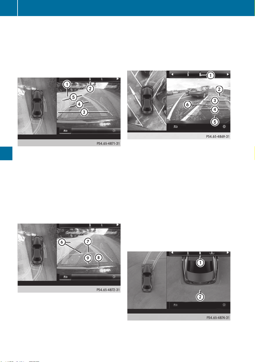
R
the rear section of an HGV
R
a slanted post
Use the guidelines only for orientation.
Approach objects no further than the bottom-
most guideline.
Top view with picture from the rear view
camera
:
Yellow guide line at a distance of approx-
imately 13 ft (4.0 m) from the rear of the
vehicle
;
Symbol for the split screen setting with top
view and rear view camera image
=
Guide lines for the maximum steering input
?
Yellow lane marking the course the tires will
take at the current steering wheel angle
(dynamic)
A
Yellow guide line for the vehicle width
including the exterior mirrors, for current
steering wheel angle (dynamic)
B
Vehicle center axle (marker assistance)
C
Yellow guide line at a distance of approx-
imately 3 ft (1.0 m) from the rear of the vehi-
cle
D
Bumper
E
Red guide line at a distance of approximately
12 in (0.30 m) from the rear of the vehicle
The guide lines are shown when the transmis-
sion is in position k.
The distance specifications only apply to
objects that are at ground level.
Top view with picture from the front cam-
era
:
Symbol for the split screen setting with top
view and front camera image
;
Yellow guide line at a distance of approx-
imately 13 ft (4.0 m) from the front of the
vehicle
=
Yellow guide line for the vehicle width
including the exterior mirrors, for current
steering wheel angle (dynamic)
?
Yellow lane marking the course the tires will
take at the current steering wheel angle
(dynamic)
A
Red guide line at a distance of approximately
12 in (0.30 m) from the front of the vehicle
B
Yellow guide line at a distance of approx-
imately 3 ft (1.0 m) from the front of the
vehicle
Top view and enlarged rear view
:
Symbol for the split screen setting with top
view and rear view camera image enlarged
;
Red guide line at a distance of approximately
12 in (0.30 m) from the rear of the vehicle
202
Driving systems
Driving and parking
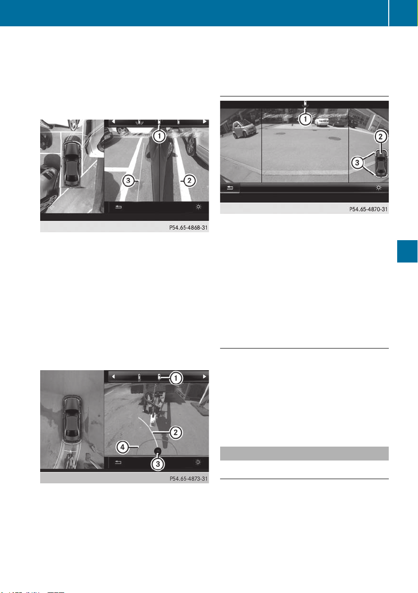
This view assists you in estimating the distance
to the vehicle behind you.
i
This setting can also be selected as an
enlarged front view.
Top view with image from the camera in
the exterior mirrors
:
Symbol for setting the top view with image
from the forward camera in the exterior mir-
rors
;
Yellow guide line for the vehicle width
including the exterior mirrors (right side of
vehicle)
=
Yellow guide line for the vehicle width
including the exterior mirrors (left side of
vehicle)
i
You can also select the camera setting in the
exterior mirrors for the rear-facing view.
Top view with trailer view
:
Symbol for the trailer view setting
;
Trailer drawbar marker assistant
=
Ball coupling
?
Red guide line at a distance of approximately
0.30 m from the ball coupling
The lines are shown at the level of the trailer
coupling.
i
For technical reasons, the ball coupling of
the trailer tow hitch is only partially visible in
the multimedia system display.
180° view
:
Symbol for the full screen setting with rear
view camera image
;
Your vehicle
=
Warning displays for Parking Assist
PARKTRONIC
i
180° view can also be selected as front
view.
Select this view when you are driving out of an
exit and the view of crossing traffic is restricted,
for example.
Exiting 360° camera display mode
The 360° camera display is stopped:
R
when you select transmission position j, or
R
when you are driving at moderate speeds
The previous display appears in the multimedia
system. You can also switch the display by
selecting the & symbol in the display and
pressing the controller to confirm.
ATTENTION ASSIST
General notes
ATTENTION ASSIST helps you during long,
monotonous journeys, such as on highways. It is
active in the 37 mph (60 km/h) to 125 mph
(200 km/h) range. If ATTENTION ASSIST
detects typical indicators of fatigue or increas-
ing lapses in concentration on the part of the
driver, it suggests taking a break.
Driving systems
203
Driving and parking
Z
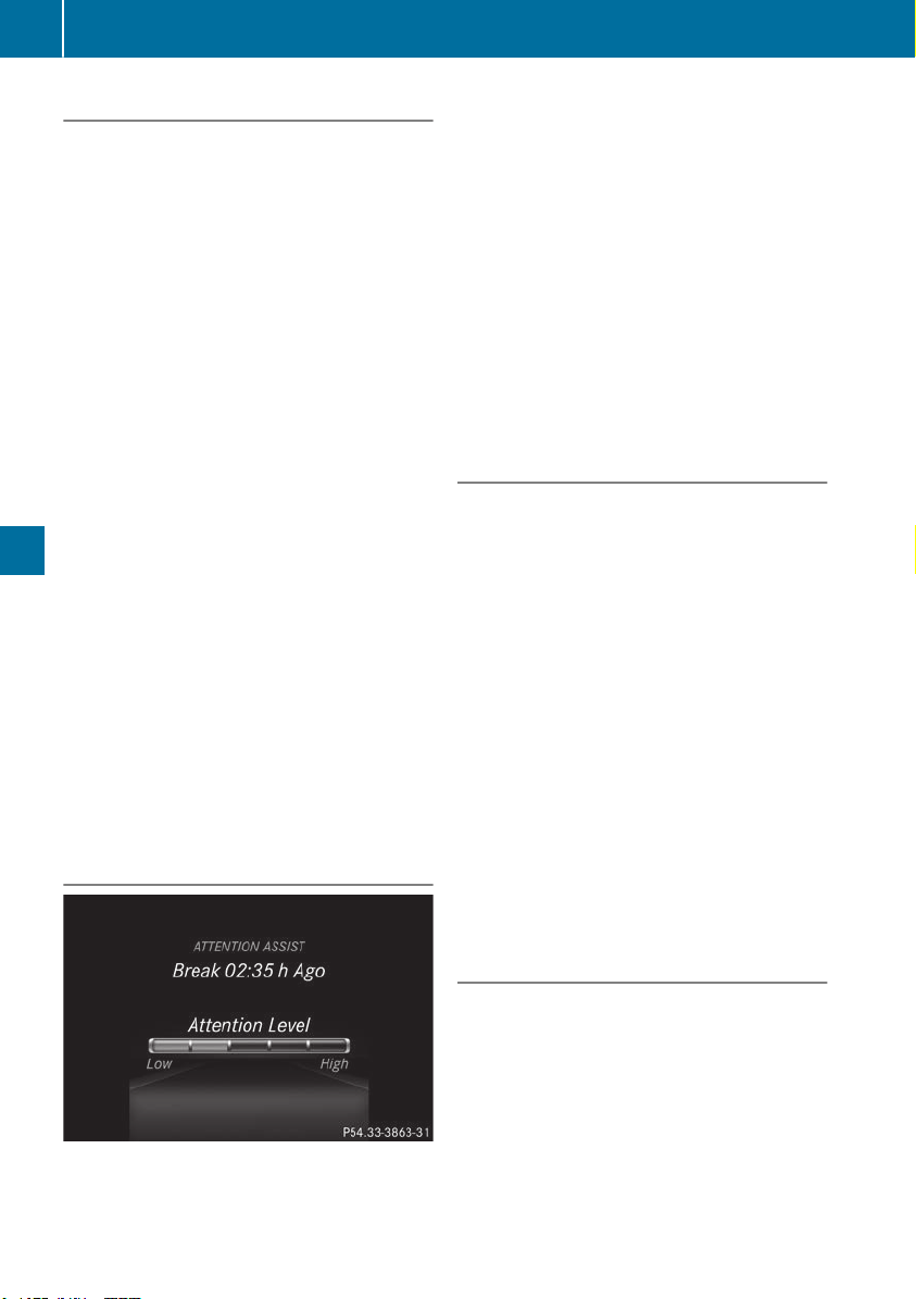
Important safety notes
ATTENTION ASSIST is only an aid to the driver. It
might not always recognize fatigue or increasing
inattentiveness in time or fail to recognize them
at all. The system is not a substitute for a well-
rested and attentive driver.
The functionality of ATTENTION ASSIST is
restricted and warnings may be delayed or not
occur at all:
R
if the length of the journey is less than approx-
imately 30 minutes
R
if the road condition is poor, e.g. if the surface
is uneven or if there are potholes
R
if there is a strong side wind
R
if you have adopted a sporty driving style with
high cornering speeds or high rates of accel-
eration
R
if you are predominantly driving slower than
37 mph (60 km/h) or faster than 125 mph
(200 km/h)
R
if you are driving with the Active Steering
Assist of Active Distance Assist DISTRONIC
activated
R
if the time has been set incorrectly
R
in active driving situations, such as when you
change lanes or change your speed
The attention level evaluation is deleted and
restarts when the journey is continued, if:
R
you switch off the engine
R
you take off your seat belt and open the driv-
er's door, e.g. for a change of drivers or to
take a break
Displaying the attention level
You can have current status information dis-
played in the assistance menu (Y page 237) of
the on-board computer.
X
Select the Assistance display for ATTENTION
ASSIST using the on-board computer
(Y page 237).
The following information is displayed:
R
The length of the journey since the last break.
R
The attention level determined by ATTENTION
ASSIST, displayed in a bar display in five levels
from high to low.
R
If ATTENTION ASSIST is unable to calculate
the attention level and cannot output a warn-
ing, the System suspendedSystem suspended message
appears. The bar display then changes the
display, e.g. if you are driving at a speed below
37 mph (60 km/h) or above 125 mph
(200 km/h).
Activating ATTENTION ASSIST
X
Activate ATTENTION ASSIST using the on-
board computer (Y page 238).
The system determines the attention level of
the driver depending on the setting selected:
Standard selected: the sensitivity with which
the system determines the attention level is set
to normal.
Sensitive selected: the sensitivity is set higher.
The attention level detected by ATTENTION
ASSIST is adapted accordingly and the driver is
warned earlier.
When ATTENTION ASSIST is deactivated, the
À symbol and OFF appear in the multifunc-
tion display in the assistance display when the
engine is running.
When ATTENTION ASSIST has been deactivated,
it is automatically reactivated after the engine
has been stopped. The sensitivity selected cor-
responds to the last selection activated (stand-
ard/sensitive).
Warning in the multifunction display
If fatigue or increasing lapses in concentration
are detected, a warning appears in the multi-
function display: AttentionAttention Assist:Assist: TakeTake aa
Break!Break!
In addition to the message shown in the multi-
function display, you will then hear a warning
tone.
X
If necessary, take a break.
X
Confirm the message by pressing the a
button on the steering wheel.
204
Driving systems
Driving and parking
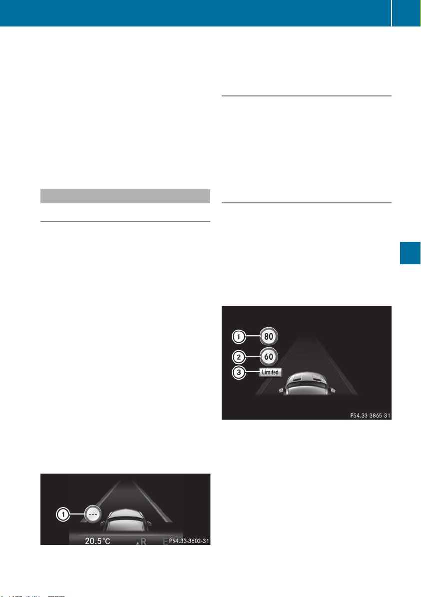
On long journeys, take regular breaks in good
time to allow yourself to rest. If you do not take
a break, you will be warned again after
15 minutes at the earliest. This will only happen
if ATTENTION ASSIST still detects typical indi-
cators of fatigue or increasing lapses in concen-
tration.
Vehicles with COMAND: if a warning is issued
in the multifunction display, a service station
search is performed in COMAND. You can select
a service station and navigation to this service
station will then begin. This function can be acti-
vated and deactivated in COMAND.
Traffic Sign Assist
General notes
Traffic Sign Assist displays the maximum speed
permitted to the driver in the instrument cluster.
The data stored in the navigation system and
general traffic regulations are used to determine
the current speed limit.
As Traffic Sign Assist is a map-based system,
traffic signs put up temporarily (e.g. near road-
works) are not detected.
If a traffic sign that is relevant to your vehicle is
passed, the display of the speed limits is upda-
ted.
Traffic signs with a restriction indicated by an
additional sign (e.g. in wet conditions) are also
shown.
The traffic signs are only displayed with the
restrictions if:
R
The regulation must be observed with the
restriction, or
R
Traffic Sign Assist is unable to determine
whether the restriction applies
If Traffic Sign Assist is unable to determine a
maximum permitted speed from any of the avail-
able sources, no speed limit is displayed in the
instrument cluster either.
Traffic Sign Assist is not available in all coun-
tries. In this case, symbol : is shown in the
assistance graphic display (Y page 237).
Important safety notes
Traffic Sign Assist is only an aid and is not always
able to correctly display speed limits. Traffic
signs always have priority over the Traffic Sign
Assist display.
The system may be either functionally impaired
or temporarily unavailable if the information in
the digital street map of the navigation system is
incorrect or out of date.
Instrument cluster display
Displaying the assistance graphic
X
Call up the assistance graphics display func-
tion using the on-board computer
(Y page 237).
X
Select the Traffic Sign Assist display.
Detected traffic signs are displayed in the
instrument cluster.
Speed limit with unknown restriction
:
Maximum permitted speed
;
Maximum permitted speed for vehicles for
which the restriction in the additional sign is
relevant
=
Additional sign for unknown restriction
A maximum permitted speed of 80 mph
(80 km/h) and a speed limit of 60 mph
(60 km/h) with an unknown restriction apply.
Driving systems
205
Driving and parking
Z

Lane Tracking package
General notes
The Lane Tracking package consists of Blind
Spot Assist (Y page 206) and Lane Keeping
Assist (Y page 207).
Blind Spot Assist
General notes
Blind Spot Assist monitors the areas on either
side of the vehicle that are not visible to the
driver with two lateral, rear-facing radar sen-
sors. A warning display in the exterior mirrors
draws your attention to vehicles detected in the
monitored area. If you then switch on the cor-
responding turn signal to change lane, you will
also receive an optical and audible warning.
Blind Spot Assist supports you from a speed of
approximately 20 mph (30 km/h).
Important safety notes
G
WARNING
Blind Spot Assist does not react to:
R
vehicles overtaken too closely on the side,
placing them in the blind spot area
R
vehicles which approach with a large speed
differential and overtake your vehicle
As a result, Blind Spot Assist may not give
warnings in such situations. There is a risk of
an accident.
Always observe the traffic conditions care-
fully, and maintain a safe lateral distance.
Blind Spot Assist is only an aid. It may fail to
detect some vehicles and is no substitute for
attentive driving. Always ensure that there is
sufficient distance to the side for other road
users and obstacles.
i
USA only:
This device has been approved by the FCC as
a "Vehicular Radar System". The radar sensor
is intended for use in an automotive radar
system only. Removing, tampering with, or
altering the device will void any warranties,
and is not permitted by the FCC. Do not tam-
per with, alter, or use in any non-approved
way.
Any unauthorized modification to this device
could void the user’s authority to operate the
equipment.
Radar sensors
The radar sensors for Blind Spot Assist are inte-
grated into the rear bumper. Make sure that the
bumpers are free from dirt, ice or slush. The
sensors must not be covered, for example by
cycle racks or overhanging loads. Following a
severe impact or in the event of damage to the
bumpers, have the function of the radar sensors
checked at a qualified specialist workshop.
Blind Spot Assist may no longer work properly.
Monitoring area
In particular, the detection of obstacles can be
impaired if:
R
there is dirt on the sensors or anything else
covering the sensors
R
there is poor visibility, e.g. due to fog, heavy
rain, snow or spray
R
there are narrow vehicles, e.g. motorcycles or
bicycles
R
the road has very wide lanes
R
the road has narrow lanes
R
you are not driving in the middle of the lane
R
there are barriers or similar lane borders
Vehicles in the monitoring range are then not
indicated.
At a distance of around 1.6 ft (0.5 m) ; from the
vehicle, Blind Spot Assist monitors the area up
to 10 ft (3 m) next to = and behind : your
vehicle, as shown in the picture.
206
Driving systems
Driving and parking
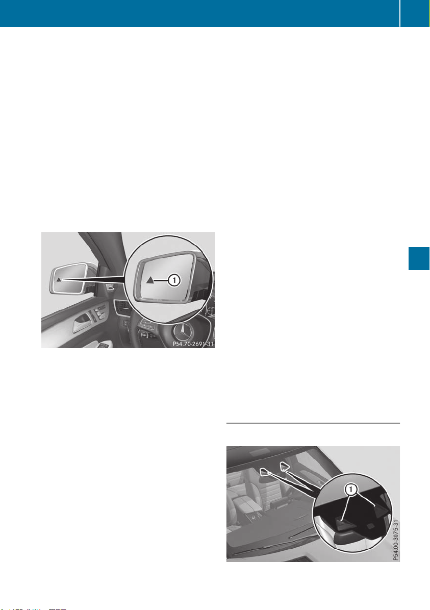
If the lanes are narrow, vehicles driving in the
lane beyond the lane next to your vehicle may be
indicated, especially if the vehicles are not driv-
ing in the middle of their lane. This may be the
case if there are vehicles driving at the inner
edge of their lanes.
Due to the nature of the system:
R
warnings may be issued in error when driving
close to crash barriers or similar solid lane
borders.
R
the warning is canceled when driving for an
extended period next to long vehicles, such as
trucks.
Warning lamp
Blind Spot Assist is not active at speeds below
approximately 20 mph (30 km/h). Vehicles in
the monitoring range are then not indicated.
:
Warning lamp
If Blind Spot Assist is activated, warning lamp :
in the exterior mirrors lights up yellow at speeds
of up to 20 mph (30 km/h). At speeds above
20 mph (30 km/h), the warning lamp goes out
and Blind Spot Assist is operational.
If a vehicle is detected within the blind spot
monitoring range at speeds above 20 mph
(30 km/h), warning lamp : on the correspond-
ing side lights up red. This warning is always
emitted when a vehicle enters the blind spot
monitoring range from behind or from the side.
When you overtake a vehicle, the warning only
occurs if the difference in speed is less than
7 mph (12 km/h).
If you select the reverse gear, Blind Spot Assist
is not operational.
The brightness of the warning lamps is auto-
matically adapted to the brightness of the sur-
roundings.
Collision warning
If a vehicle is detected in the monitoring range of
Blind Spot Assist and you switch on the corre-
sponding turn signal, a double warning tone
sounds. Red warning lamp : flashes. If the turn
signal remains on, detected vehicles are indica-
ted by the flashing of red warning lamp :.
There are no further warning tones.
Switching on Blind Spot Assist
X
Make sure that Blind Spot Assist is activated
in the on-board computer (Y page 238).
X
Turn the SmartKey to position 2 in the igni-
tion lock.
Warning lamps : in the exterior mirrors light
up red for approximately 1.5 seconds and
then turn yellow.
Towing a trailer
When you attach a trailer, make sure you have
correctly established the electrical connection.
This can be accomplished by checking the trailer
lighting. In this event, Blind Spot Assist is deac-
tivated. The warning lamp lights up yellow in the
exterior mirrors and the Blind Spot AssistBlind Spot Assist
Not Available When Towing a TrailerNot Available When Towing a Trailer
See Operator's ManualSee Operator's Manual message appears in
the multifunction display.
i
You can deactivate the warning lamps in the
exterior mirrors.
To do so, switch off Blind Spot Assist when:
R
the SmartKey is in position 2 in the igni-
tion lock
R
the engine is not running
Lane Keeping Assist
General notes
:
Lane Keeping Assist camera
Driving systems
207
Driving and parking
Z

Lane Keeping Assist monitors the area in front of
your vehicle with camera :, which is mounted
at the top of the windshield. Lane Keeping Assist
detects lane markings on the road and can warn
you before you leave your lane unintentionally.
This function is available in the range between
40 mph and 120 mph (60 km/h and 200 km/h).
A warning may be given if a front wheel passes
over a lane marking. It will warn you by means of
intermittent vibration in the steering wheel for
up to 1.5 seconds.
Important safety notes
G
WARNING
Lane Keeping Assist cannot always clearly
detect lane markings.
In such cases, Lane Keeping Assist can:
R
give an unnecessary warning
R
not give a warning
There is a risk of an accident.
Always pay particular attention to the traffic
situation and keep within the lane, especially
if Lane Keeping Assist alerts you.
G
WARNING
The Lane Keeping Assist warning does not
return the vehicle to the original lane. There is
a risk of an accident.
You should always steer, brake or accelerate
yourself, in particular if warned by Lane Keep-
ing Assist.
If you fail to adapt your driving style, Lane Keep-
ing Assist can neither reduce the risk of an acci-
dent nor override the laws of physics. Lane
Keeping Assist cannot take into account the
road, traffic and weather conditions. Lane Keep-
ing Assist is merely an aid. You are responsible
for the distance to the vehicle in front, for vehi-
cle speed, for braking in good time and for stay-
ing in your lane.
The Lane Keeping Assist does not keep the vehi-
cle in the lane.
The system may be impaired or may not function
if:
R
there is poor visibility, e.g. due to insufficient
illumination of the road, or due to snow, rain,
fog or heavy spray
R
there is glare, e.g. from oncoming traffic, the
sun or reflection from other vehicles (e.g. if
the road surface is wet)
R
the windshield is dirty, fogged up, damaged or
covered, for instance by a sticker, in the vicin-
ity of the camera
R
there are no or several unclear lane markings
for one lane, e.g. roadworks
R
the lane markings are worn away, dark or cov-
ered up, e.g. by dirt or snow
R
the distance to the vehicle in front is too short
and thus the lane markings cannot be detec-
ted
R
the lane markings change quickly, e.g. lanes
branch off, cross one another or merge
R
the road is narrow and winding
R
there are highly variable shade conditions on
the roadway
Switching on Lane Keeping Assist
X
Switch on Active Lane Keeping Assist using
the on-board computer; to do so, select
StandardStandard or AdaptiveAdaptive (Y page 238).
If you drive at speeds above 40 mph
(60 km/h) and lane markings are detected,
the lines in the assistance graphic are shown
in green (Y page 237). Lane Keeping Assist is
ready for use.
Standard
If StandardStandard is selected, no warning vibration
occurs if:
R
you switch on the turn signals. In this event,
the warnings are suppressed for a certain
period of time.
R
a driving safety system intervenes, e.g. ABS,
BAS or ESP
®
.
Adaptive
When AdaptiveAdaptive is selected, no warning vibra-
tion occurs if:
R
you have switched on the turn signal; in this
event, the warnings are suppressed for a cer-
tain period of time.
R
a driving safety system intervenes, e.g. ABS,
BAS or ESP
®
.
208
Driving systems
Driving and parking

R
you accelerate hard, e.g. kickdown.
R
you brake hard.
R
you steer actively, e.g. swerve to avoid an
obstacle or change lanes quickly.
R
you cut the corner on a sharp bend.
To ensure that you are warned only when nec-
essary and in good time if you cross the lane
markings, the system detects certain conditions
and warns you accordingly.
The warning vibration occurs earlier if:
R
you approach the outer lane marking on a
bend
R
the road has very wide lanes, e.g. a freeway
R
the system detects solid lane markings
The warning vibration occurs later if:
R
the road has narrow lanes
R
you cut the corner on a bend
Driving Assistance Plus package
General notes
The Driving Assistance Plus Package consists of
Active Distance Assist DISTRONIC(Y page 171),
Active Blind Spot Assist (Y page 209) and
Active Lane Keeping Assist (Y page 211).
Active Blind Spot Assist
General notes
Active Blind Spot Assist monitors the areas on
either side of the vehicle that are not directly
visible to the driver with two lateral, rear-facing
radar sensors. A warning lamp lights up in the
exterior mirrors and draws your attention to
vehicles detected in the monitored area. If you
then switch on the corresponding turn signal to
change lanes, you will also receive a visual and
audible collision warning. If a risk of lateral col-
lision is detected, corrective braking may help
you avoid a collision. Before a course-correcting
brake application, Active Blind Spot Assist eval-
uates the space in the direction of travel and at
the sides of the vehicle. For this, Active Blind
Spot Assist uses the forward-facing radar sen-
sors.
Active Blind Spot Assist supports you from a
speed of approximately 20 mph (30 km/h).
Important safety notes
Active Blind Spot Assist is only an aid and is not
a substitute for attentive driving.
G
WARNING
Active Blind Spot Assist does not react to:
R
vehicles overtaken too closely on the side,
placing them in the blind spot area
R
vehicles which approach with a large speed
differential and overtake your vehicle
As a result, Active Blind Spot Assist may nei-
ther give warnings nor intervene in such sit-
uations. There is a risk of an accident.
Always observe the traffic conditions care-
fully, and maintain a safe lateral distance.
i
USA only: This device has been approved by
the FCC as a "Vehicular Radar System". The
radar sensor is intended for use in an auto-
motive radar system only. Removal, tamper-
ing, or altering of the device will void any war-
ranties, and is not permitted by the FCC. Do
not tamper with, alter, or use in any non-
approved way.
Any unauthorized modification to this device
could void the user's authority to operate the
equipment.
i
Canada only: This device complies with
RSS-210 of Industry Canada. Operation is
subject to the following two conditions:
1. This device may not cause interference,
and
2. This device must accept any interference
received, including interference that may
cause undesired operation of the device.
Removal, tampering, or altering of the device
will void any warranties, and is not permitted.
Do not tamper with, alter, or use in any non-
approved way.
Any unauthorized modification to this device
could void the user's authority to operate the
equipment.
Radar sensors
The Active Blind Spot Assist radar sensors are
integrated into the front and rear bumpers and
behind a cover in the radiator trim. Make sure
that the bumpers and the cover in the radiator
grill are free of dirt, ice or slush. The sensors
must not be covered, for example by cycle racks
Driving systems
209
Driving and parking
Z
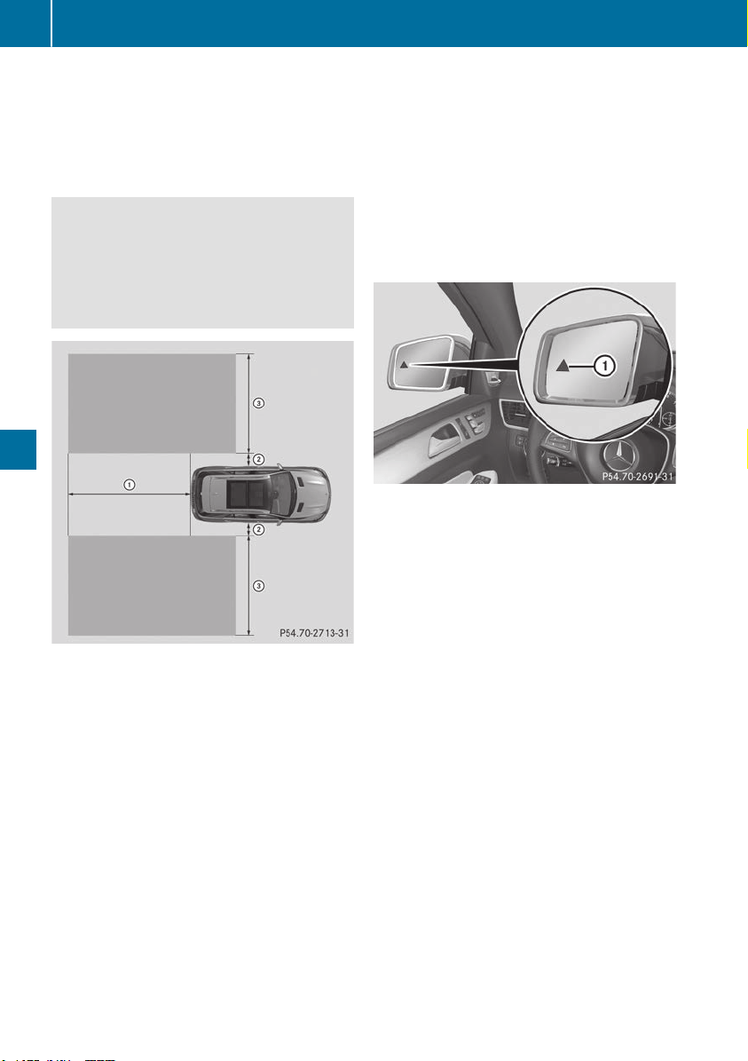
or overhanging loads. Following an accident or
in the event of damage to the bumpers, have the
function of the radar sensors checked at a quali-
fied specialist workshop. Active Blind Spot
Assist may otherwise no longer work properly.
Monitoring area
G
WARNING
Active Blind Spot Assist does not detect all
traffic situations and road users. There is a
risk of an accident.
Always make sure that there is sufficient dis-
tance on the side for other traffic or obstacles.
At a distance of approximately 1.6 ft (0.5 m) ;
from the vehicle, Active Blind Spot Assist mon-
itors the area up to 10 ft (3 m) next to = and
behind : your vehicle, as shown in the picture.
In particular, the detection of obstacles can be
impaired if:
R
there is dirt on the sensors or anything else
covering the sensors
R
poor visibility, e.g. due to rain, snow or spray
Vehicles in the monitoring range are then not
reliably indicated.
Active Blind Spot Assist may not detect narrow
vehicles, such as motorcycles or bicycles, or
may only detect them too late.
If the lanes are narrow, vehicles driving in the
lane beyond the lane next to your vehicle may be
indicated, especially if the vehicles are not driv-
ing in the middle of their lane. This may be the
case if there are vehicles at the inner edge of
your lane.
On very wide lanes, vehicles in the adjacent lane
may not be shown if they are too far away.
Due to the nature of the system:
R
warnings may be issued in error when driving
close to crash barriers or similar solid lane
borders.
R
warnings may be interrupted when driving
alongside particularly long vehicles, e.g.
trucks, for a prolonged time.
Warning lamp
:
Warning lamp
Active Blind Spot Assist is not operational at
speeds below approximately 20 mph (30 km/h).
Vehicles in the monitoring range are then not
indicated.
If Active Blind Spot Assist is activated, warning
lamp : in the exterior mirrors lights up yellow
at speeds of up to 20 mph (30 km/h). At speeds
above 20 mph (30 km/h), the warning lamp
goes out and Active Blind Spot Assist is opera-
tional.
If a vehicle is detected within the monitoring
range at speeds above approximately 20 mph
(30 km/h), warning lamp : on the correspond-
ing side lights up red. This warning lamp always
lights up when a vehicle enters the blind spot
monitoring range from behind or from the side.
When you overtake a vehicle, the warning only
occurs if the difference in speed is less than
7 mph (12 km/h).
If you select the reverse gear, Active Blind Spot
Assist is not operational.
The brightness of the warning lamps is auto-
matically adapted to the brightness of the sur-
roundings.
210
Driving systems
Driving and parking

Visual and acoustic collision warning
If you switch on the turn signals to change lanes
and a vehicle is detected in the side monitoring
range, you receive a visual and acoustic collision
warning. You then hear a double warning tone
and red warning lamp : flashes. If the turn sig-
nal remains on, detected vehicles are indicated
by the flashing of red warning lamp :. There are
no further warning tones.
Course-correcting brake application
If Active Blind Spot Assist detects a risk of a lat-
eral collision in the monitoring range, a course-
correcting brake application is carried out. This
is meant to assist you in avoiding a collision.
G
WARNING
A course-correcting brake application cannot
always prevent a collision. There is a risk of an
accident.
Always steer, brake or accelerate yourself,
especially if Active Blind Spot Assist warns
you or makes a course-correcting brake appli-
cation. Always maintain a safe distance at the
sides.
If a course-correcting brake application occurs,
red warning lamp : flashes in the exterior mir-
ror and a double warning tone sounds. In addi-
tion, a display underlining the danger of a side
collision appears in the multifunction display.
In very rare cases, the system may make an
inappropriate brake application. A course-cor-
recting brake application may be interrupted at
any time by countersteering slightly or acceler-
ating.
The course-correcting brake application is avail-
able in the speed range between 20 mph
(30 km/h) and 120 mph (200 km/h).
Either no braking application, or a course-cor-
recting brake application adapted to the driving
situation occurs if:
R
there are vehicles or obstacles, e.g. crash
barriers, located on both sides of your vehicle.
R
a vehicle approaches you too closely at the
side.
R
you have adopted a sporty driving style with
high cornering speeds.
R
you clearly brake or accelerate.
R
a driving safety system intervenes, e.g. ESP
®
or PRE-SAFE
®
Brake.
R
ESP
®
is switched off.
R
the offroad program is activated (vehicles
without the Offroad Engineering package).
R
the Offroad or Offroad Plus drive program is
activated (vehicles with the Off-Road Engi-
neering package).
R
the LOW RANGE offroad gear is activated
(vehicles with the Offroad Engineering pack-
age).
R
a loss of tire pressure or a defective tire is
detected.
Switching on Active Blind Spot Assist
X
Make sure that Active Blind Spot Assist
(Y page 238) is activated in the on-board
computer.
X
Turn the SmartKey to position 2 in the igni-
tion lock.
Warning lamps : in the exterior mirrors light
up red for approximately 1.5 seconds and
then turn yellow.
Towing a trailer
When you attach a trailer, make sure you have
correctly established the electrical connection.
This can be accomplished by checking the trailer
lighting. Active Blind Spot Assist is then deacti-
vated. The indicator lamp lights up yellow in the
exterior mirrors and the Active Blind SpotActive Blind Spot
Asst. Not Available When Towing aAsst. Not Available When Towing a
Trailer See Operator's ManualTrailer See Operator's Manual message
appears in the multifunction display.
Active Lane Keeping Assist
General notes
Active Lane Keeping Assist monitors the area in
front of your vehicle by means of multifunction
camera : at the top of the windshield. Various
different areas to the front, rear and side of your
Driving systems
211
Driving and parking
Z

vehicle are also monitored with the aid of the
radar sensor system. Active Lane Keeping
Assist detects lane markings on the road and
can warn you before you leave your lane unin-
tentionally. If you do not react to the warning, a
lane-correcting application of the brakes can
bring the vehicle back into the original lane.
This function is available in a speed range
between 40 mph and 120 mph (60 km/h and
200 km/h).
For Active Lane Keeping Assist to assist you
when driving, the radar sensor system must be
operational.
Important safety notes
If you fail to adapt your driving style, Active Lane
Keeping Assist can neither reduce the risk of
accident nor override the laws of physics. Active
Lane Keeping Assist cannot take into account
road, weather or traffic conditions. Active Lane
Keeping Assist is only an aid. You are responsi-
ble for the distance to the vehicle in front, for
vehicle speed, for braking in good time and for
staying in your lane.
Active Lane Keeping Assist cannot continuously
keep your vehicle in its lane.
G
WARNING
Active Lane Keeping Assist cannot always
clearly detect lane markings.
In such cases, Active Lane Keeping Assist
can:
R
give an unnecessary warning and then
make a course-correcting brake application
R
neither give a warning nor intervene
There is a risk of an accident.
Always pay particular attention to the traffic
situation and keep within the lane, especially
if Active Lane Keeping Assist alerts you. Ter-
minate the intervention in a non-critical driv-
ing situation.
The system may be impaired or may not function
if:
R
there is poor visibility, e.g. due to insufficient
illumination of the road, or due to snow, rain,
fog or heavy spray
R
there is glare, e.g. from oncoming traffic, the
sun or reflection from other vehicles (e.g. if
the road surface is wet)
R
the windshield is dirty, fogged up, damaged or
covered, for instance by a sticker, in the vicin-
ity of the camera
R
there are no or several unclear lane markings
for one lane, e.g. roadworks
R
the lane markings are worn away, dark or cov-
ered up, e.g. by dirt or snow
R
the distance to the vehicle in front is too short
and thus the lane markings cannot be detec-
ted
R
the lane markings change quickly, e.g. lanes
branch off, cross one another or merge
R
the road is narrow and winding
R
there are highly variable shade conditions on
the roadway
R
no vehicle is detected in the adjacent lane and
there are broken lane markings
Warning vibration in the steering wheel
A warning may be given if a front wheel passes
over a lane marking. It will warn you by means of
intermittent vibration in the steering wheel for
up to 1.5 seconds.
In order that you are warned only when neces-
sary and in good time if you cross the lane mark-
ing, the system detects certain conditions and
warns you accordingly.
The warning vibration occurs earlier if:
R
you approach the outer lane marking on a
bend
R
the road has very wide lanes, e.g. a freeway
R
the system detects solid lane markings
The warning vibration occurs later if:
R
the road has narrow lanes
R
you cut the corner on a bend
Lane-correcting brake application
G
WARNING
A lane-correcting brake application cannot
always bring the vehicle back into the original
lane. There is a risk of an accident.
Always steer, brake or accelerate yourself,
especially if Active Lane Keeping Assist warns
you or makes a lane-correcting brake appli-
cation.
G
WARNING
Active Lane Keeping Assist does not detect
traffic conditions or road users. In very rare
212
Driving systems
Driving and parking
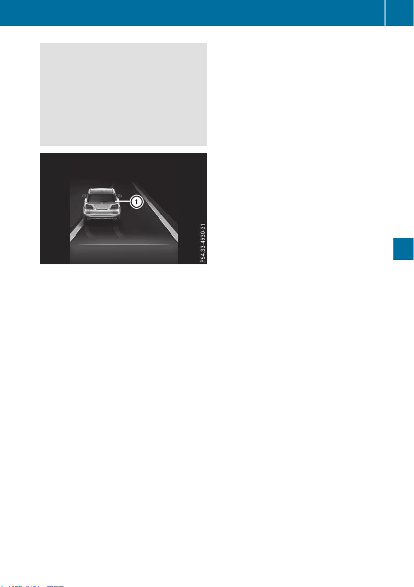
cases, the system may make an inappropriate
brake application, e.g. after intentionally driv-
ing over a solid lane marking. There is a risk of
an accident.
An inappropriate brake application may be
interrupted at any time if you steer slightly in
the opposite direction. Always make sure that
there is sufficient distance on the side for
other traffic or obstacles.
If you leave your lane, under certain circumstan-
ces the vehicle will brake briefly on one side.
This is meant to assist you in bringing the vehicle
back to the original lane.
If a lane-correcting brake application occurs,
display : appears in the multifunction display.
A lane-correcting brake application can be made
after driving over a solid or broken lane marking.
Before this, a warning must be given by means of
intermittent vibration in the steering wheel. In
addition, a lane with lane markings on both sides
must have been detected.
In the case of a broken lane marking being
detected, a lane-correcting brake application
can only be made if a vehicle has been detected
in the adjacent lane. The following vehicles can
have an influence on brake application: oncom-
ing traffic, vehicles that are overtaking and vehi-
cles that are driving parallel to your vehicle.
i
A further lane-correcting brake application
can only occur after your vehicle has returned
to the original lane.
No lane-correcting brake application occurs if:
R
you clearly and actively steer, brake or accel-
erate
R
you cut the corner on a sharp bend
R
you have switched on the turn signal
R
a driving safety system intervenes, e.g. ESP
®
,
PRE-SAFE
®
Brake or Active Blind Spot Assist
R
you have adopted a sporty driving style with
high cornering speeds or high rates of accel-
eration
R
ESP
®
is switched off
R
the transmission is not in position h
R
on vehicles with a trailer tow hitch, the elec-
trical connection to the trailer has been cor-
rectly established
R
the Off-road program is activated (vehicles
without the Off-road Engineering Package)
R
the Off-road or Off-road Plus drive program is
activated (vehicles with the Off-road Engi-
neering Package)
R
the LOW RANGE off-road gear is activated
(vehicles with the Off-road Engineering Pack-
age)
R
an obstacle has been detected in the lane in
which you are driving
R
when a loss of tire pressure or a defective tire
has been detected and displayed
There is a possibility that the Active Lane Keep-
ing Assist could misjudge the given traffic sit-
uation. An inappropriate brake application may
be interrupted at any time if you:
R
steer slightly in the opposite direction
R
switch on the turn signal
R
clearly brake or accelerate
A lane-correcting brake application is interrup-
ted automatically if:
R
a driving safety system intervenes, e.g. ESP
®
,
PRE-SAFE
®
Brake or Active Blind Spot Assist
R
lane markings are no longer detected
Switching on Active Lane Keeping Assist
X
Switch on Active Lane Keeping Assist using
the on-board computer; to do so, select
StandardStandard or AdaptiveAdaptive (Y page 238).
If you drive at speeds above 40 mph
(60 km/h) and lane markings are detected,
the lines in the assistance graphic are shown
in green (Y page 237). Active Lane Keeping
Assist is ready for use.
If StandardStandard is selected, no warning vibration
occurs if:
Driving systems
213
Driving and parking
Z

R
you switch on the turn signals. In this event,
the warnings are suppressed for a certain
period of time.
R
a driving safety system intervenes, such as
ABS, BAS or ESP
®
.
When AdaptiveAdaptive is selected, no warning vibra-
tion occurs if:
R
you switch on the turn signals. In this event,
the warnings are suppressed for a certain
period of time.
R
a driving safety system intervenes, e.g.
ABS, BAS or ESP
®
.
R
you accelerate hard, e.g. kickdown.
R
you brake hard.
R
you steer actively, e.g. swerve to avoid an
obstacle or change lanes quickly.
R
you cut the corner on a sharp bend.
Towing a trailer
When you attach a trailer, make sure you have
correctly established the electrical connection.
This can be accomplished by checking the trailer
lighting. Lane-correcting brake application does
not take place when towing a trailer. Active Lane
Keeping Assist is not activated and the lines in
the assistance graphic are gray.
Off-road driving systems
4MATIC (permanent four-wheel drive)
4MATIC ensures that all four wheels are perma-
nently driven. Together with ESP
®
and 4ETS, it
improves the traction of your vehicle whenever
a drive wheel spins due to insufficient grip.
If you fail to adapt your driving style, 4MATIC can
neither reduce the risk of accident nor override
the laws of physics. 4MATIC cannot take
account of road, weather and traffic conditions.
4MATIC is only an aid. You are responsible for
the distance to the vehicle in front, for vehicle
speed, for braking in good time and for staying in
your lane.
!
Never tow the vehicle with one axle raised.
This may damage the transfer case. Damage
of this sort is not covered by the Mercedes-
Benz Limited Warranty. All wheels must
remain either on the ground or be fully raised.
Observe the instructions for towing the vehi-
cle with all wheels in full contact with the
ground.
!
A function or performance test should only
be carried out on a two-axle dynamometer.
Before you operate the vehicle on such a
dynamometer, please consult a qualified
workshop. You could otherwise damage the
drive train or the brake system.
i
In wintry driving conditions, the maximum
effect of 4MATIC can only be achieved if you
use winter tires (M+S tires), with snow chains
if necessary.
Further information about "Driving off-road"
(Y page 165).
DSR (Downhill Speed Regulation)
General notes
DSR is an aid to assist you when driving down-
hill. It keeps the speed of travel at the speed
selected on the on-board computer. The steeper
the downhill gradient, the greater the DSR brak-
ing effect on the vehicle. When driving on flat
stretches of road or on an uphill gradient, the
DSR braking effect is minimal or nonexistent.
DSR controls the vehicle’s speed when it is acti-
vated and the transmission is in position h, k
or i. You can drive at a higher or a lower speed
than that set on the on-board computer at any
time by accelerating or braking.
Important safety notes
G
WARNING
If the speed driven and the set speed deviate
and you activate DSR on a slippery road sur-
face, the wheels may lose traction. There is an
increased danger of skidding and accidents.
Before switching DSR on, please take into
consideration the road surface and the differ-
ence between driving speed and the set
speed.
If you fail to adapt your driving style, DSR can
neither reduce the risk of accident nor override
the laws of physics. DSR cannot take account of
road, weather and traffic conditions. DSR is only
an aid. You are responsible for the distance to
the vehicle in front, for vehicle speed, for brak-
ing in good time and for staying in your lane.
You are always responsible for keeping control
of the vehicle and for assessing whether the
downhill gradient can be managed. DSR may not
always be able to keep to the set speed, depend-
214
Driving systems
Driving and parking
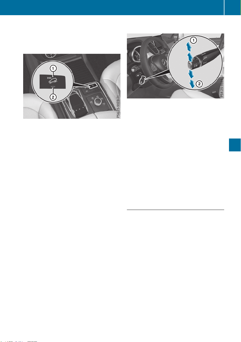
ing on road surface and tire conditions. Select a
set speed suitable for the prevailing conditions
and when necessary, apply the brakes manually.
Activating DSR
X
Press button :.
Indicator lamp ; lights up.
The à DSR symbol appears in the multi-
function display.
You can only activate DSR when driving at
speeds below 25 mph (40 km/h).
If the current vehicle speed is too high, the Ã
DSR symbol appears in the multifunction display
with the Max. Speed 25 mphMax. Speed 25 mph message (Can-
ada: 40 km/h40 km/h).
If you have activated DSR and you change the
drive program, DSR is deactivated. If you switch
between the offroad and offroad plus drive pro-
grams, DSR remains activated.
Deactivating DSR
X
Press button :.
Indicator lamp ; goes out.
The à DSR symbol appears in the multi-
function display with the OffOff message.
On vehicles with the Off-road Engineering Pack-
age, if you select a different drive program, DSR
is also deactivated. If you switch between the
Offroad programs, DSR remains activated.
DSR switches off automatically if you drive
faster than 28 mph (Canada: 45 km/h). The
à DSR symbol appears in the multifunction
display with the OffOff message. The status indi-
cator in the multifunction display goes out. You
also hear a warning. On vehicles with the Off-
road Engineering Package, if you select a differ-
ent onroad/offroad program, DSR is also deac-
tivated.
Changing the set speed
X
To increase or reduce the set speed in
1 mphincrements (Canada: 1 km/h incre-
ments): briefly press the cruise control lever
up : for a higher set speed or down ; for a
lower set speed.
The set speed appears in the multifunction
display with the à DSR symbol.
When DSR is activated, you can change the set
speed to a value between 1 mph and 11 mph
(Canada: between 2 km/h and 18 km/h).
i
The DSR set speed is always changed in
1 mph increments (Canada: 1 km/h incre-
ments). This is regardless of whether you
press the cruise control lever to or beyond the
pressure point.
Off-road program (vehicles without the
Off-Road Engineering package)
General notes
Select the Offroad program for easily negotia-
ble off-road terrain, e.g. dirt tracks, gravel or
sandy surfaces. The engine's torque is restric-
ted to a limited degree and the drive wheels can
spin. The spinning wheels produce a cutting
effect for better traction. ABS, ESP
®
and 4ETS
programs especially adapted to off-road driving
are activated. A gentle accelerator pedal curve
is also selected, i.e. the accelerator pedal must
be depressed much further in order to acceler-
ate.
You can select the Offroad drive program at
speeds below 60 mph (96 km/h). The DriveDrive
program "Offroad" Max. Speed 60 mphprogram "Offroad" Max. Speed 60 mph
message appears in the multifunction display. If
you drive at speeds of more than 60 mph
(96 km/h) and select the Offroad drive pro-
gram, the Drive More SlowlyDrive More Slowly message
Driving systems
215
Driving and parking
Z
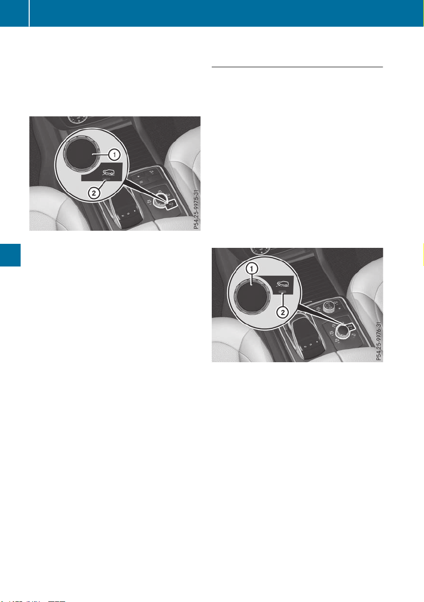
appears in the multifunction display. The last
active drive program is selected again.
Do not use the Offroad program on roads that
are snow-covered or icy or if you have installed
your vehicle with snow chains.
Selecting the Offroad program
Selecting the Offroad program
X
To select drive program: turn DYNAMIC
SELECT controller : until indicator lamp ;
lights up.
The Drive Program "Offroad1" Max.Drive Program "Offroad1" Max.
Speed 60 mphSpeed 60 mph message appears in the mul-
tifunction display.
The vehicle is raised by +2.4 in (60 mm).
The vehicle is lowered to normal level again if
you:
R
drive at speeds above 50 mph (80 km/h) (all
vehicles except Mercedes-AMG vehicles)
R
drive at speeds above 43 mph (70 km/h)
(Mercedes-AMG vehicles)
R
drive between 40 mph (64 km/h) and 50 mph
(80 km/h) for approximately 20 seconds (all
vehicles except Mercedes-AMG vehicles).
R
drive at speeds between 40 mph (64 km/h)
and 43 mph (70 km/h) for approximately
20 seconds (Mercedes-AMG vehicles)
The vehicle changes from the Offroad drive pro-
gram to the Comfort drive program if you drive
faster than 70 mph (112 km/h).
The Drive More SlowlyDrive More Slowly message appears in
the multifunction display.
Further information about "Driving off-road"
(Y page 165).
Off-road programs (vehicles with Off-
Road Engineering package)
General notes
The Offroad and Offroad Plus drive programs
assist you when driving off-road. The engine's
performance characteristics and the gearshift-
ing characteristics of the automatic transmis-
sion are adapted for this purpose. ABS, ESP
®
and 4ETS programs especially adapted to off-
road driving are activated. An accelerator pedal
curve suitable for the terrain is selected, i.e. the
accelerator pedal must be depressed further to
accelerate.
Do not use the Offroad or Offroad Plus drive
programs on roads that are snow-covered or icy,
or if you have installed your vehicle with snow
chains.
Offroad drive program
:
DYNAMIC SELECT controller
;
Offroad program indicator lamp
Select the Offroad program for easily negotia-
ble off-road terrain, e.g. dirt tracks, gravel or
sandy surfaces. The engine's torque is restric-
ted to a limited degree and the drive wheels can
spin. The spinning wheels produce a cutting
effect for better traction. ABS, ESP
®
and 4ETS
programs especially adapted to off-road driving
are activated. A gentle accelerator pedal curve
is also selected, i.e. the accelerator pedal must
be depressed much further in order to acceler-
ate.
You can select the Offroad drive program at
speeds below 60 mph (96 km/h). The DriveDrive
Program "Offroad" Max. Speed 60 mphProgram "Offroad" Max. Speed 60 mph
message appears in the multifunction display. If
you drive at speeds above 60 mph (96 km/h)
and select the Offroad drive program, the
Drive More SlowlyDrive More Slowly message appears in the
216
Driving systems
Driving and parking
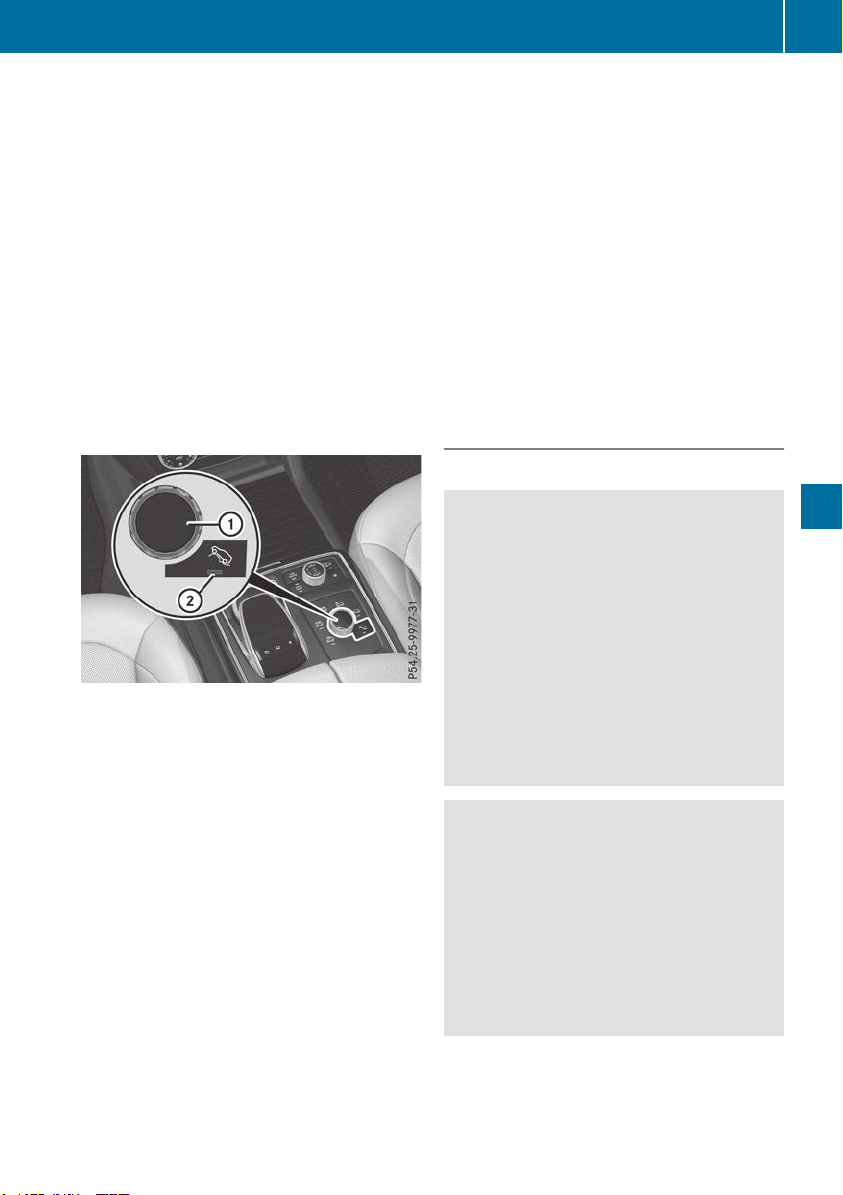
multifunction display. The last active drive pro-
gram is selected again.
Selecting the Offroad program
X
To select a drive program: turn DYNAMIC
SELECT controller : until indicator lamp ;
lights up.
The Drive program "Offroad" Max.Drive program "Offroad" Max.
speed 60 mphspeed 60 mph message appears in the mul-
tifunction display.
The vehicle is raised by +1.2 in (30 mm).
The vehicle changes from the Offroad drive pro-
gram to the Comfort drive program if you drive
faster than 70 mph (112 km/h).
The Drive more slowlyDrive more slowly message appears in
the multifunction display.
Offroad Plus drive program
:
DYNAMIC SELECT controller
;
Offroad Plus drive program indicator lamp
Select the Offroad Plus drive program for rough
terrain, e.g. for steep and/or uneven terrain or
for driving on rocky terrain.
Your vehicle has an automatically activated dif-
ferential lock for the transfer case. It controls
the balance between the front and rear axles.
The differential lock improves the vehicle's trac-
tion. 4ETS (Y page 70) controls the balance
between both wheels on an axle.
Selecting the Offroad Plus drive program
X
To select drive program: turn DYNAMIC
SELECT controller : until indicator lamp ;
lights up.
The Drive program "Offroad Plus"Drive program "Offroad Plus"
Max.Max. speedspeed 2525 mphmph message appears in the
multifunction display.
R
The Offroad Plus program is selected and
the vehicle is raised by +1.2 in (30 mm)
compared with the Offroad drive program.
R
DSR is switched on.
R
The differential lock is closed.
You can select the Offroad Plus drive program at
speeds below 25 mph (40 km/h).
The Offroad Plus drive program automatically
switches to the Offroad drive program if you
drive faster than 30 mph (45 km/h). The DriveDrive
more slowlymore slowly message appears in the multi-
function display.
Further information about "Driving off-road"
(Y page 165).
LOW RANGE off-road gear (vehicles
with the Off-Road Engineering package)
Important safety notes
G
WARNING
If you select the LOW RANGE off-road gear on
a slippery road surface, the wheels could lose
traction:
R
if you remove your foot from the accelera-
tor pedal when driving
R
if off road ABS intervenes when braking
If the wheels lose traction. the vehicle can no
longer be steered. There is an increased dan-
ger of skidding and accidents.
Never select the LOW RANGE off-road gear
when driving on slippery road surfaces.
G
WARNING
If you do not wait for the transfer case gear
change process to complete, the transfer
case could remain in the neutral position. The
power transmission to the driven wheels is
then interrupted. There is a danger of the
vehicle rolling away unintentionally. There is a
risk of an accident.
Wait until the transfer case shift process is
completed.
Do not turn off the engine while changing gear
and do not shift the automatic transmission to
another position.
Driving systems
217
Driving and parking
Z
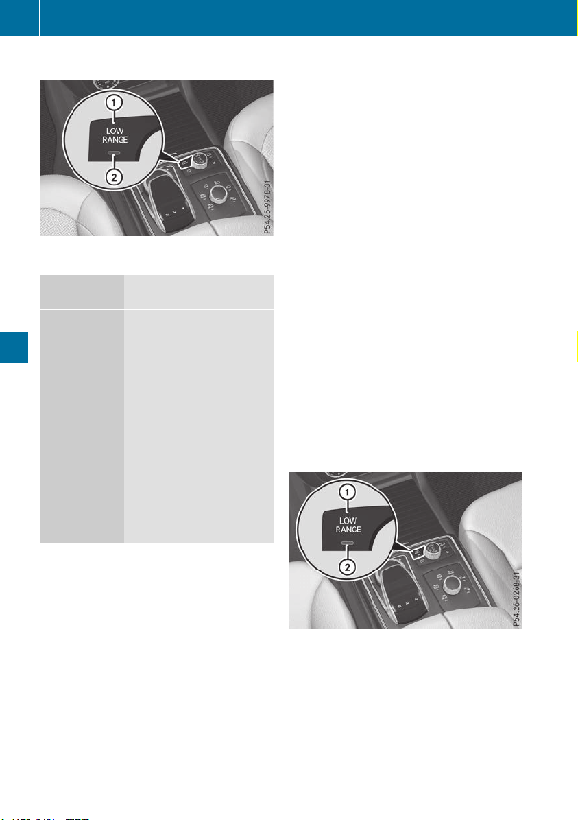
General notes
:
LOW RANGE offroad gear button
;
LOW RANGE offroad gear indicator lamp
HIGH RANGE
Position for all normal on-
road driving conditions
LOW RANGE
Offroad position for driving
off-road and fording
The transmission ratio
between the engine and
wheels is only approx-
imately one third of that in
the HIGH RANGE road posi-
tion. Drive torque is thus
proportionately higher.
Do not use LOW RANGE:
R
on slippery road surfaces,
e.g. in the case of slush
R
on snow or ice-covered
roads
R
if you have mounted snow
chains to your vehicle
The LOW RANGE offroad gear assists you in
driving off-road and when fording. When LOW
RANGE is engaged, the engine’s performance
characteristics and the gearshifting character-
istics of the automatic transmission are adapted
for this purpose.
Further information about "Driving off-road"
(Y page 165). You will find information about
driving safety systems in conjunction with
LOW RANGE in the "Safety" section (Y page 66).
From HIGH RANGE to LOW RANGE
!
Only change from LOW RANGE to HIGH
RANGE if:
R
the engine is running.
R
the transmission is in position N
R
you are driving at a speed below 40 km/h
X
Press LOW RANGE button :.
Indicator lamp ; flashes.
When the gear change is complete, indicator
lamp ; lights up. LOW RANGE indicator
appears in the multifunction display and in the
status indicator.
While indicator lamp ; is flashing, you can
cancel the gear change by pressing LOW
RANGE button : again.
i
You cannot activate LOW RANGE if the
SPORT drive program is activated. The LOWLOW
RANGE Not in Drive Program "Sport"RANGE Not in Drive Program "Sport"
message then appears in the multifunction
display.
From LOW RANGE to HIGH RANGE
!
Only change from LOW RANGE to HIGH
RANGE if:
R
the engine is running.
R
the transmission is in position N
R
you are driving at a speed below 50 km/h
X
Press LOW RANGE button :.
Indicator lamp ; flashes.
When the gear change is complete, indicator
lamp ; goes out. In the multifunction dis-
play, the LOW RANGE OffLOW RANGE Off message appears
and the status indicator goes out.
While indicator lamp ; is flashing, you can
cancel the gear change by pressing LOW
RANGE button : again.
218
Driving systems
Driving and parking
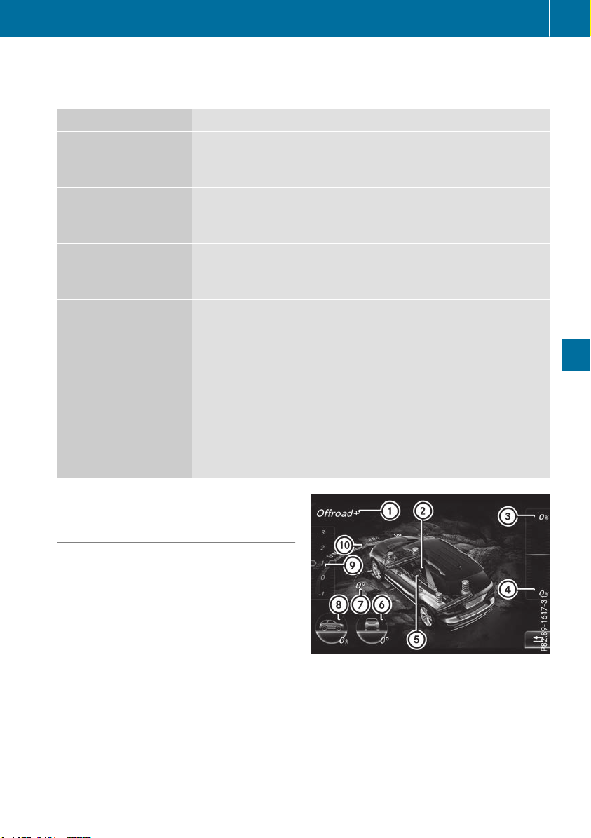
Messages in the multifunction display
If a gear change process has not been successful, the following messages may be displayed in the
multifunction display:
Display messages
Possible causes/consequences and MM Solutions
LOW RANGE Max.LOW RANGE Max.
Speed 24 mphSpeed 24 mph
You have been driving faster than 24 mph (40 km/h). Additionally, the
indicator lamp on the button in the center console is flashing.
X
Slow down to change gear.
LOW RANGE Shift toLOW RANGE Shift to
Position N BrieflyPosition N Briefly
The transmission is in position h and you are driving at below
40 km/h.
X
To shift gear, shift the transmission to position i.
LOW RANGE ShiftingLOW RANGE Shifting
Canceled PleaseCanceled Please
ReactivateReactivate
The gear change process was not carried out.
X
Ensure that all gear change conditions are fulfilled and carry out the
gear change process again.
LOW RANGE StopLOW RANGE Stop
Apply Parking BrakeApply Parking Brake
A warning tone also sounds. The gear change process has not been
completed. LOW RANGE is in the neutral position. There is no con-
nection between the engine and the drive wheels.
!
Do not drive any further. You could otherwise damage the vehi-
cle's drive train.
X
Stop the vehicle. Take into account the road and traffic conditions
when doing this.
X
Depress the electric parking brake (Y page 157).
X
Carry out the gear change process again.
If the gear change process has been carried out, the LOW RANGELOW RANGE
Stop Apply Parking BrakeStop Apply Parking Brake message disappears.
Driving dynamics display in the
COMAND display (vehicles with the Off-
Road Engineering package)
General notes
The driving dynamics display allows you to see
the selected drive program and additional infor-
mation about the vehicle's operating status in
the COMAND display.
:
Drive program selected
;
Status of the differential lock for the transfer
case
=
Accelerator pedal position shown in %
?
Brake pedal position shown in %
A
Condition of the LOW RANGE offroad gear
B
Angle of inclination
C
Steering angle
D
Uphill or downhill gradient in percentage
Driving systems
219
Driving and parking
Z
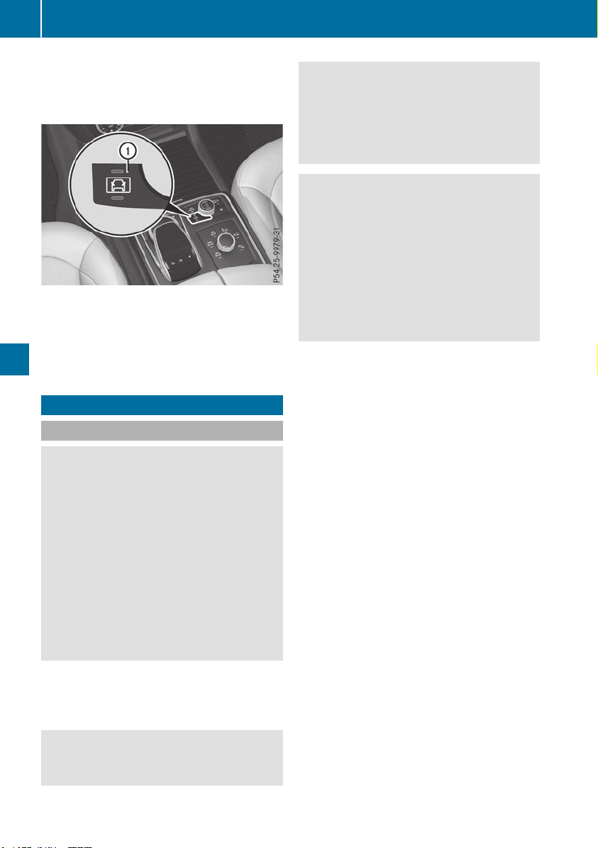
E
Level control
F
Compass with angle scale
Activating the driving dynamics display
X
Switch on COMAND (see the Digital Opera-
tor's Manual).
X
Press button :.
The driving dynamics display appears in the
COMAND display.
Towing a trailer
Important safety notes
G
WARNING
Installing an unsuitable ball coupling may
result in overloading of the trailer tow hitch
and the rear axle. This applies especially if the
ball coupling in question is longer or angled
differently. This could seriously impair the
driving characteristics and the trailer can
come loose. There is a risk of an accident.
You should only ever install a ball coupling
that has the permissible dimensions and that
is designed to meet your trailer-towing
requirements. Do not modify the ball coupling
or the trailer tow hitch.
You will find the values approved by the manu-
facturer on the vehicle identification plates and
those for the towing vehicle under "Technical
data" (Y page 394).
G
WARNING
If the ball coupling is not installed correctly or
not secured with the bolt provided and the
corresponding spring cotter, the trailer may
come loose. There is a risk of an accident.
Always install and secure the ball coupling as
described. Before every journey, ensure that
the ball coupling is secured with the bolt and
the corresponding spring cotter.
G
WARNING
When the vehicle/trailer combination begins
to lurch, you could lose control of it. The vehi-
cle/trailer combination could even rollover.
There is a risk of an accident.
On no account should you attempt to
straighten up the vehicle/trailer combination
by increasing the speed. Reduce vehicle
speed and do not countersteer. Apply the
brake as necessary.
Please observe the manufacturer's operating
instructions for the trailer coupling if a detach-
able trailer coupling is used.
Couple and uncouple the trailer carefully. If you
do not couple the trailer to the towing vehicle
correctly, the trailer could become detached.
Make sure that the following values are not
exceeded:
R
the permissible trailer drawbar noseweight
R
the permissible trailer load
R
the permissible rear axle load of the towing
vehicle
R
the maximum permissible gross vehicle
weight of both the towing vehicle and the
trailer
The applicable permissible values, which must
not be exceeded, can be found:
R
in the vehicle documents
R
on the identification plates for the trailer tow
hitch and the trailer
R
on the vehicle identification plate
If the values differ, the lowest value applies.
When towing a trailer, your vehicle's handling
characteristics will be different in comparison
with when driving without a trailer.
The vehicle/trailer combination:
R
is heavier
R
is restricted in its acceleration and gradient-
climbing capability
R
has an increased braking distance
220
Towing a trailer
Driving and parking

R
is affected more by strong crosswinds
R
demands more sensitive steering
R
has a larger turning circle
This could impair the handling characteristics.
When towing a trailer, always adjust your speed
to the current road and weather conditions. Do
not exceed the maximum permissible speed for
your vehicle/trailer combination.
Notes on towing a trailer
General notes
!
If you have a trailer tow hitch retrofitted,
changes to the cooling system and drive train
may be necessary, depending on the vehicle
type.
If you have a trailer tow hitch retrofitted,
observe the anchorage points on the chassis
frame.
R
Do not exceed the legally prescribed maxi-
mum speed for vehicle/trailer combinations
in the relevant country.
This lowers the risk of an accident.
R
Only install an approved trailer coupling on
your vehicle.
More information on availability and installa-
tion can be obtained at any qualified special-
ist workshop.
R
The bumpers of your vehicle are not suitable
for installing detachable trailer couplings.
R
Do not install hired trailer couplings or other
detachable trailer couplings on the bumpers
of your vehicle.
R
If you no longer need the ball coupling,
remove it from the ball coupling recess. This
will reduce the risk of damage to the ball cou-
pling.
When towing a trailer, set the tire pressure on
the rear axle of the towing vehicle for the max-
imum load. You will find the values in the tire
pressure table in the fuel filler flap of the vehicle
(Y page 369).
Please note that when towing a trailer, the fol-
lowing driving systems have limited availability
or are not available at all:
R
Parking Assist PARKTRONIC (Y page 188)
R
Blind Spot Assist (Y page 206)
R
Active Lane Keeping Assist (Y page 211)
On vehicles without level control, the height of
the ball coupling will alter according to the load
placed on the vehicle. If necessary, use a trailer
with a height-adjustable drawbar.
You will find installing dimensions and loads
under "Technical data" (Y page 394).
Driving tips
Also observe the notes on pulling away with a
trailer (Y page 138).
The maximum permissible speed for vehicle/
trailer combinations depends on the type of
trailer. Before beginning the journey, check the
trailer's documents to see what the maximum
permissible speed is for your trailer. Observe the
legally permissible maximum speed in the rele-
vant country.
For certain Mercedes-Benz vehicles, the maxi-
mum permissible rear axle load is increased
when towing a trailer. See "Technical data" to
find out whether this applies to your vehicle
(Y page 394). If you utilize any of the added
maximum rear axle load when towing a trailer,
the vehicle/trailer combination may not exceed
a maximum speed of 60 mph (100 km/h) for
reasons concerning the operating permit. This
also applies in countries in which the maximum
permissible speed for car/trailer combinations
is greater than 60 mph (100 km/h).
When towing a trailer, your vehicle's handling
characteristics will be different in comparison
with when driving without a trailer.
Use the left-hand steering wheel paddle shifter
to shift into a lower gear in good time on long
and steep downhill gradients.
This also applies if you have activated cruise
control or Active Distance Assist DISTRONIC.
This will use the braking effect of the engine, so
that less braking will be required to maintain the
speed. This relieves the load on the brake sys-
tem and prevents the brakes from overheating
and wearing too quickly. If you need additional
braking, depress the brake pedal repeatedly
rather than continuously.
Driving tips
If the trailer swings from side to side:
X
Do not accelerate.
X
Do not counter-steer.
X
Brake if necessary.
Towing a trailer
221
Driving and parking
Z
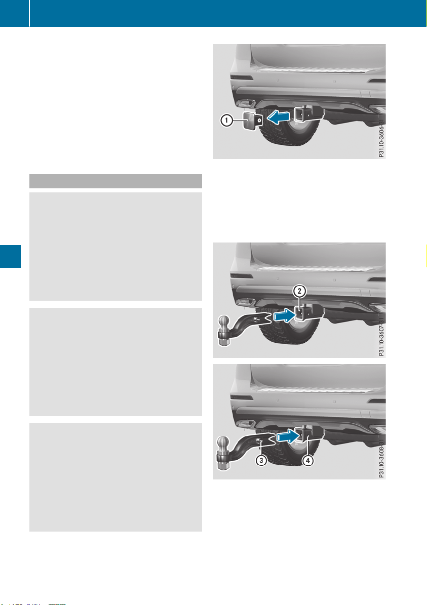
R
Maintain a greater distance from the vehicle
in front than when driving without a trailer.
R
Avoid braking abruptly. If possible, brake gen-
tly at first to allow the trailer to run on. Then,
increase the braking force rapidly.
R
The values given for gradient-climbing capa-
bilities from a standstill refer to sea level.
When driving in mountainous areas, note that
the power output of the engine and, conse-
quently, the vehicle's gradient-climbing capa-
bility, decreases with increasing altitude.
Installing the ball coupling
G
WARNING
If the ball coupling is not correctly installed
and secured, it can come loose during the
journey and endanger other road users. There
is a risk of an accident and injury.
Always install and secure the ball coupling as
described. Before every journey, ensure that
the ball coupling is secured with the bolt and
the corresponding spring cotter.
G
WARNING
If the ball coupling is not installed correctly or
not secured with the bolt provided and the
corresponding spring cotter, the trailer may
come loose. There is a risk of an accident.
Always install and secure the ball coupling as
described. Before every journey, ensure that
the ball coupling is secured with the bolt and
the corresponding spring cotter.
G
WARNING
If the ball coupling is not installed and secured
correctly the trailer may come loose. There is
a risk of an accident.
Install and secure the ball coupling as descri-
bed in the ball coupling installation instruc-
tions. Make sure that the ball coupling is
installed and secured correctly before every
journey.
X
Pull protective cap : in the direction of the
arrow, out of the ball coupling recess.
X
Stow protective cap : so that it cannot be
thrown around.
Observe the loading guidelines (Y page 295)
and the safety notes regarding stowage
spaces (Y page 295).
X
Insert the ball coupling horizontally into ball
coupling recess ; in the direction of the
arrow until the holes in ball coupling = are in
line with the holes in ball coupling recess ?.
222
Towing a trailer
Driving and parking
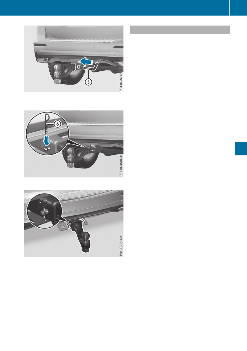
X
Slide bolt A into the hole in the ball coupling
recess and the ball coupling to the stop.
X
Secure the bolt using spring cotter B.
X
Check the ball coupling, bolt and spring cotter
for correct installation.
If the ball coupling cannot be correctly mounted,
remove the ball coupling. Under these circum-
stances, the ball coupling must not be used for
trailer towing.
Have the entire trailer tow hitch checked at a
qualified specialist workshop.
Coupling up a trailer
!
Do not connect the trailer's brake system (if
featured) to the hydraulic brake system of the
towing vehicle, as the latter is equipped with
an anti-lock brake system. Doing so will result
in a loss of function of the brake systems of
both the vehicle and the trailer.
X
Shift the transmission to position j.
X
Apply the vehicle's electric parking brake.
X
Start the engine.
X
Vehicles with AIRMATIC Package: select
normal level and the Comfort drive program.
X
Switch off the engine.
X
Close the doors and tailgate.
X
Couple up the trailer.
X
Establish the electrical connection between
the vehicle and the trailer.
X
Check that the trailer lighting system is work-
ing.
X
Push the combination switch upwards/down-
wards and check whether the corresponding
turn signal on the trailer flashes.
A trailer that is connected is recognized only
when the electrical connection is established
correctly and when the lighting system is work-
ing properly. The function of other systems also
depends on this, for example:
R
ESP
®
R
Parking Assist PARKTRONIC
R
Active Parking Assist
R
Parking Package with rear view camera
R
Active Blind Spot Assist
R
Active Lane Keeping Assist
i
Vehicles with the AIRMATIC Package: if you
couple up a trailer, the vehicle always remains
at normal level. When coupling up a trailer,
please observe the following:
R
If the normal level has not been set man-
ually, the vehicle is automatically lowered
to normal level. This is the case if a speed of
5 mph (8 km/h) is reached.
R
The Sport drive program is not available.
These restrictions apply to all accessories
powered through a connection to the trailer
power socket of your vehicle, e.g. a bicycle
carrier.
Observe the maximum permissible trailer
dimensions (width and length).
Towing a trailer
223
Driving and parking
Z

Most U.S. states and all Canadian provinces
require by law:
R
Safety chains between the towing vehicle and
the trailer. The chains should be cross-wound
under the trailer drawbar. They must be fas-
tened to the vehicle's trailer coupling, not to
the bumper or the axle.
Leave enough play in the chains to make tight
cornering possible.
R
A separate brake system for certain types of
trailer.
R
Safety switch for braked trailers. Check the
specific legal requirements applicable to your
state.
If the trailer becomes detached from the tow-
ing vehicle, the safety feature triggers the
trailer brakes.
Towing a trailer
There are numerous legal requirements con-
cerning the towing of a trailer, e.g. speed restric-
tions. Make sure that your car/trailer combina-
tion complies with the local regulations:
R
in your place of residence
R
in the location to which you are driving
The police and local authorities can provide reli-
able information.
Observe the following when towing a trailer:
R
To gain driving experience and to become
accustomed to the new handling characteris-
tics, you should practice the following in a
traffic-free location:
-
cornering
-
stopping
-
backing up
R
Before driving, check:
-
trailer tow hitch
-
safety switch for braked trailers
-
safety chains
-
electrical connections
-
lights
-
wheels
R
Adjust the exterior mirrors to provide an
unobstructed view of the rear section of the
trailer.
R
If the trailer has electronically controlled
brakes, pull away carefully. Brake manually
using the brake controller and check whether
the brakes function correctly.
R
Secure any objects on the trailer to prevent
the cargo from slipping when the vehicle is in
motion.
R
When you couple up a trailer, check at regular
intervals that the load is firmly secured. If the
trailer is equipped with trailer lights and
brakes, check the trailer to ensure that these
are working.
R
Bear in mind that the handling will be less
stable when towing a trailer than when driving
without one. Avoid sudden steering move-
ments.
R
The vehicle/trailer combination is heavier,
accelerates more slowly, has a decreased
gradient climbing capability and a longer
braking distance.
It is more susceptible to side winds and
requires more careful steering.
R
If possible, do not brake suddenly, but instead
depress the brake pedal moderately at first so
that the trailer can activate its brakes. Then
increase the pressure on the brake pedal.
R
If the automatic transmission repeatedly
shifts between gears on uphill or downhill gra-
dients, shift to a lower gear using the left-hand
steering wheel paddle shifter.
A lower gear and lower speed reduce the risk
of engine failure.
R
When driving downhill, shift to a lower gear to
utilize the engine's braking effect.
Avoid continuous brake application as this
may overheat the vehicle brakes and, if instal-
led, the trailer brakes.
R
If the coolant temperature increases dramat-
ically while the air-conditioning system is
switched on, switch off the air-conditioning
system.
Coolant heat can also be dissipated by open-
ing the windows and switching the ventilation
blower and the interior temperature to the
highest level.
R
When overtaking, pay particular attention to
the extended length of your vehicle/trailer
combination.
Due to the length of the vehicle/trailer com-
bination, you require additional road space in
relation to the vehicle you are overtaking
before you can change back to the original
lane.
224
Towing a trailer
Driving and parking

Decoupling a trailer
G
WARNING
If you uncouple a trailer with the overrun
brake engaged, you could trap your hand
between the vehicle and the trailer drawbar.
There is a risk of injury.
Do not uncouple a trailer if the overrun brake
is engaged.
G
WARNING
Vehicles with level control:
The vehicle is lowered as soon as you discon-
nect the trailer cable. This could result in your
limbs or those of other people that are
between the vehicle body and tires or under-
neath the vehicle being trapped. There is a
risk of injury.
Make sure that nobody is in the immediate
vicinity of the wheel housings or under the
vehicle when you disconnect the trailer cable.
!
Do not disconnect a trailer with an engaged
overrun brake. Otherwise, your vehicle could
be damaged by the rebounding of the overrun
brake.
X
Shift the transmission to position j.
X
Apply the vehicle's electric parking brake.
X
Start the engine.
X
Close the doors and tailgate.
X
Apply the trailer's parking brake.
X
Detach the trailer cable and decouple the
trailer.
X
Switch off the engine.
Permissible trailer loads and drawbar
loads
Weight specifications
Maximum allowable gross mass
The gross vehicle weight of the trailer is calcu-
lated by adding the weight of the trailer to the
weight of the load and equipment on the trailer.
You will find installing dimensions and loads
under "Technical data" (Y page 394).
Permissible noseweight
You will find installing dimensions and loads
under "Technical data" (Y page 394).
Loading a trailer
R
When loading the trailer, make sure that nei-
ther the permissible gross weight of the trailer
nor the gross vehicle weight are exceeded.
The permissible gross vehicle weight is indi-
cated on the identification plate located on
the B-pillar on the driver's side of the vehicle.
You can find the maximum permissible values
on the type plates of your vehicle and the
trailer. When calculating how much weight
the vehicle and trailer may carry, pay atten-
tion to the respective lowest values.
R
The trailer drawbar load on the ball coupling
must be added to the rear axle load to avoid
exceeding the permissible gross axle weight.
The permissible gross vehicle weight is indi-
cated on the identification plate located on
the B-pillar on the driver's side of the vehicle.
i
Mercedes-Benz recommends a trailer load
where the trailer drawbar noseweight
accounts for 8 % to 15 % of the trailer's per-
missible gross weight.
i
The weight of additional accessories, pas-
sengers, and cargo reduces the permissible
trailer load and drawbar load for your vehicle.
Checking the vehicle and trailer weight
R
To check that the weights of the towing vehi-
cle and the trailer comply with the maximum
permissible values, have the vehicle/trailer
combination (including the driver, passen-
gers, and cargo with a fully laden trailer)
weighed on a calibrated weighbridge.
R
Check the gross axle weight rating of the front
and rear axles, the gross weight of the trailer
and the trailer drawbar noseweight.
Removing the ball coupling
X
Remove the spring cotter.
X
Remove the bolt from the ball coupling
recess.
X
Remove the ball coupling from the ball cou-
pling recess.
Towing a trailer
225
Driving and parking
Z
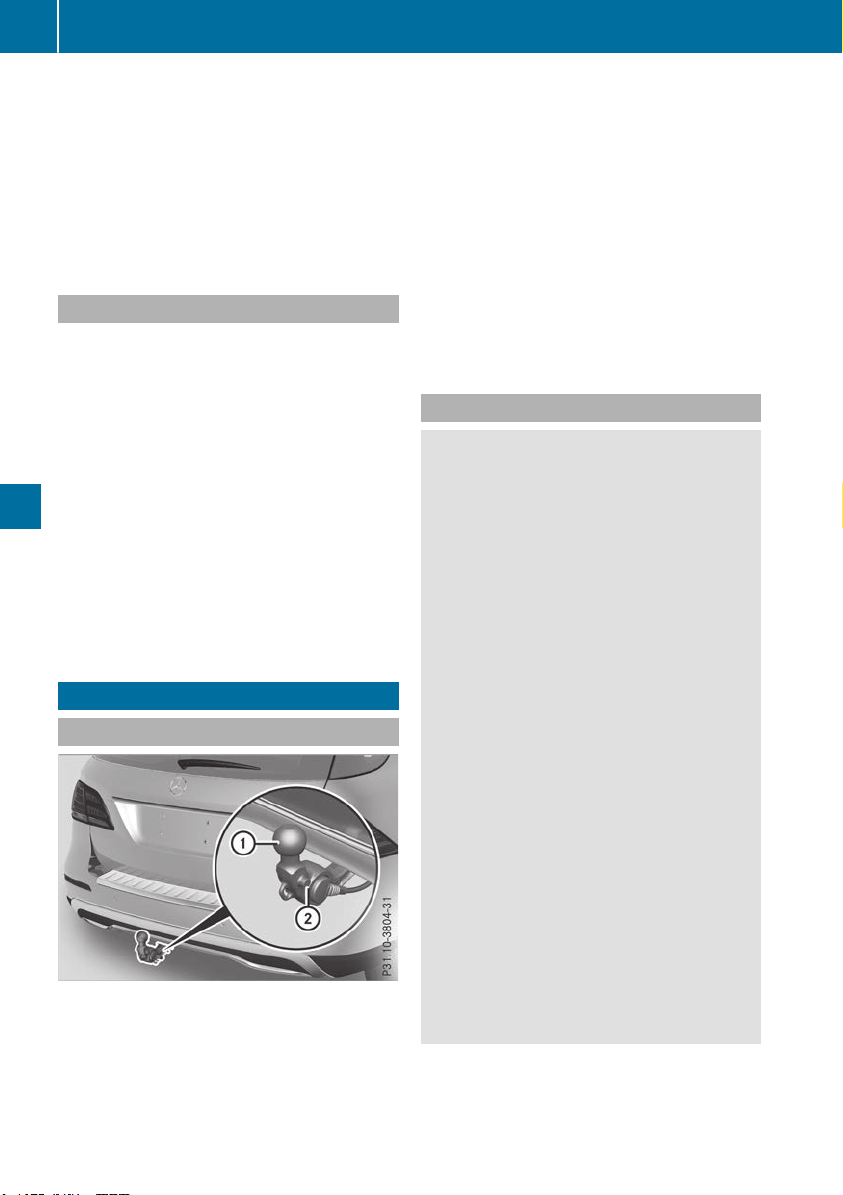
X
Clean the ball coupling if it is dirty.
X
Stow the ball coupling so that it cannot be
thrown around.
Observe the loading guidelines (Y page 295)
and the safety notes regarding stowage spaces
(Y page 295).
Information on cleaning and care of the trailer
tow hitch (Y page 331).
Trailer power supply
!
Accessories with a maximum power con-
sumption of 180 W can be connected to the
permanent power supply.
You must not charge a trailer battery using the
power supply.
The trailer socket of your vehicle is equipped at
the factory with a permanent power supply.
The permanent power supply is supplied via
trailer socket pin 4.
The trailer's permanent power supply is
switched off in the event of low vehicle supply
voltage and after six hours at the latest.
A qualified specialist workshop can provide
more information about installing the trailer
electrics.
Bicycle rack
General notes
Trailer tow hitch (example with additional
guide pin)
Depending on the bicycle rack's design, you can
transport up to four bicycles on it:
R
When attached by clamping onto ball cou-
pling :, the maximum payload is 75 kg. You
can transport up to three bicycles.
R
When attached to ball coupling : and also
guide pin ;, the maximum payload is 100 kg.
You can transport up to three bicycles.
The payload is calculated from the weight of the
bicycle rack and the load of the bicycle rack.
To transport bicycles with a gross weight
between 75 kg and 100 kg, use only bicycle
racks with additional anchorage on guide pin ;.
Important safety notes
G
WARNING
The bicycle rack can detach from the vehicle if
you
R
exceed the permissible payload of the
trailer tow hitch
R
use the bicycle rack incorrectly
R
attach the bicycle rack to the ball coupling
beneath the ball head
There is a risk of an accident.
For your safety and that of other road users,
observe the following:
R
Always observe the permissible payload of
the trailer tow hitch.
R
Use the bicycle rack only to transport bicy-
cles.
R
Always attach the bicycle rack correctly by
clamping onto the ball head and, if possible,
to the guide pin on the ball coupling as well.
R
To transport four bicycles, always use bicy-
cle racks with additional support on the ball
coupling's guide pin.
R
Use only bicycle racks approved by
Mercedes-Benz.
R
Always comply with the bicycle rack's oper-
ating manual.
!
Using unsuitable bicycle racks or using
them incorrectly can cause damage to and
fractures in the trailer tow hitch.
226
Bicycle rack
Driving and parking
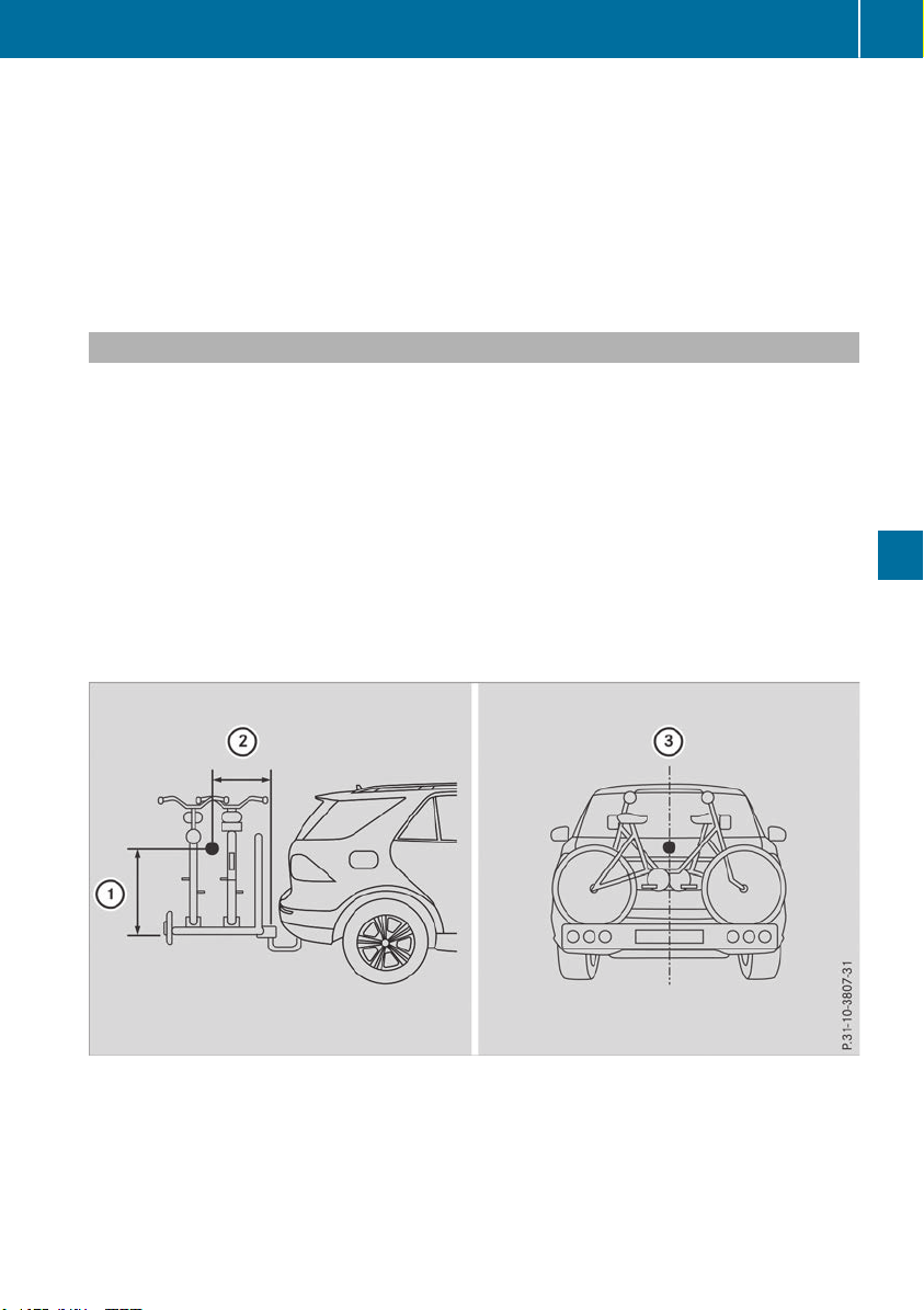
Use only bicycle racks approved by
Mercedes-Benz.
Bicycle racks cause your vehicle's driving char-
acteristics to change. The vehicle:
R
is heavier
R
is restricted in its acceleration and gradient-
climbing capability
R
has an increased braking distance
This could impair the handling characteristics.
Adapt your driving style accordingly. Maintain a
safe distance and drive carefully.
When using bicycle racks, set the tire pressure
on the rear axle of the vehicle for the maximum
load. Further information on tire pressure can be
found on the tire pressure table (Y page 354).
Loading instructions
The greater the distance between the load's center of gravity and the ball head, the higher the load
exerted on the trailer tow hitch.
Therefore, observe the following notes:
R
Attach heavy bicycles as close as possible to the vehicle.
R
Always distribute the load on the bicycle rack as symmetrically as possible to the vehicle longi-
tudinal axis.
Before loading the bicycle rack, Mercedes-Benz advises you to remove all add-on parts from the
bicycles, e.g. bicycle baskets, child seats or batteries. This will allow you to improve the aerody-
namic resistance and the bicycle rack's center of gravity.
Always secure bicycles against slipping and check that they are firmly seated at regular intervals.
Do not use tarpaulins or other covers. This could impair the driving characteristics and rear visibility.
The aerodynamic resistance would also rise, and so would the load exerted on the trailer tow hitch
as a result.
Load distribution on the bicycle rack
:
Distance in height between the center of gravity and the ball coupling
;
Distance to the rear between the center of gravity and the ball coupling
=
The center of gravity is located on the central axis of the vehicle
Bicycle rack
227
Driving and parking
Z

When loading the bicycle rack, comply with the following notes:
Number of bicycles Gross weight of bicy-
cle rack and load
Max. distance :: Max. distance ;;
3 up to 75 kg 420 mm 300 mm
4
2
up to 100 kg
2
420 mm 400 mm
Notes on towing vehicles
The vehicle is not suitable for attaching tow bar
systems, such as those used for flat towing or
dinghy towing.
Attaching or using tow bar systems may result in
damage to the vehicle.
When towing a vehicle with tow bar systems,
safe driving characteristics cannot be guaran-
teed for the towing vehicle or the towed vehicle.
The vehicle/vehicle combination may swerve.
Observe the permissible towing methods
(Y page 347) and the notes on towing with both
axles on the ground (Y page 347).
2
When transporting four bicycles or a gross weight between 75 kg and 100 kg, use only bicycle racks with
additional support on the guide pin of the trailer tow hitch.
228
Notes on towing vehicles
Driving and parking

Important safety notes
G
WARNING
If you operate information systems and com-
munication equipment integrated in the vehi-
cle when driving, you may be distracted from
the traffic situation. You could also lose con-
trol of the vehicle. There is a risk of an acci-
dent.
Only operate this equipment when the traffic
situation permits. If you are not sure that this
is possible, park the vehicle paying attention
to traffic conditions and operate the equip-
ment when the vehicle is stationary.
You must observe the legal requirements for the
country in which you are currently driving when
operating the on-board computer.
G
WARNING
If the instrument cluster has failed or mal-
functioned, you may not recognize function
restrictions in systems relevant to safety. The
operating safety of your vehicle may be
impaired. There is a risk of an accident.
Pull over as soon as it is safe to do so and
consult a qualified specialist workshop.
The on-board computer only shows messages or
warnings from certain systems in the multifunc-
tion display. You should therefore make sure
your vehicle is operating safely at all times.
For an overview, see the instrument panel illus-
tration (Y page 37).
Plug-in hybrid: be sure to read the separate
Operator's Manual. Otherwise, you may not rec-
ognize dangers.
Displays and operation
Instrument cluster lighting
The lighting in the instrument cluster, in the dis-
plays and the controls in the vehicle interior can
be adjusted using the brightness control knob.
The brightness control knob is located on the
bottom left of the instrument cluster
(Y page 37).
X
Turn the brightness control knob clockwise or
counter-clockwise.
If you turn the light switch to Ã, T or
L, the brightness is dependent upon the
brightness of the ambient light.
i
The light sensor in the instrument cluster
automatically controls the brightness of the
multifunction display.
In daylight, the displays in the instrument
cluster are not illuminated.
Speedometer with segments
The segments in the speedometer indicate
which speed range is available.
R
Cruise control activated (Y page 169):
The segments light up from the stored speed
to the maximum speed.
R
Active Distance Assist DISTRONIC activated
(Y page 171):
One or two segments in the set speed range
light up.
R
Active Distance Assist DISTRONIC detects a
vehicle in front moving more slowly than the
stored speed:
The segments between the speed of the vehi-
cle in front and the stored speed light up.
Tachometer
!
Do not drive in the overrevving range, as this
could damage the engine.
The red band in the tachometer indicates the
engine's overrevving range.
The fuel supply is interrupted to protect the
engine when the red band is reached.
Outside temperature display
You should pay special attention to road condi-
tions when temperatures are around freezing
point.
Bear in mind that the outside temperature dis-
play indicates the temperature measured and
does not record the road temperature.
The outside temperature display is in the multi-
function display (Y page 231).
Displays and operation
229
On-board computer and displays
Z
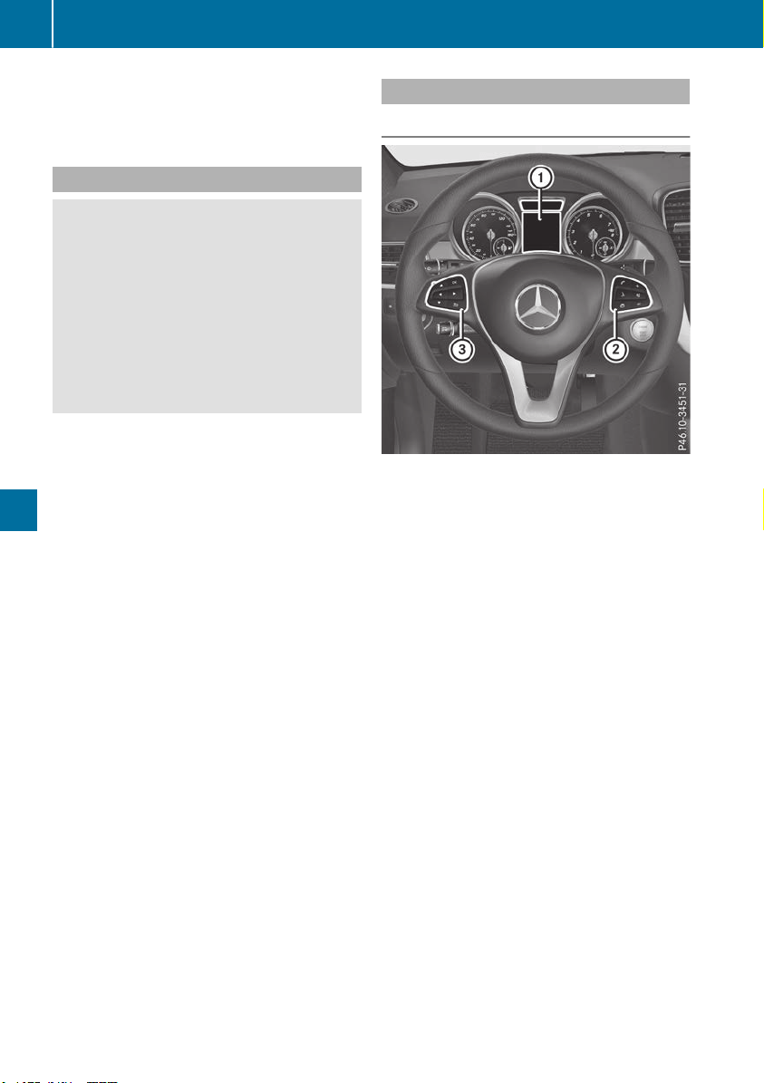
There is a short delay before a change in outside
temperature appears in the multifunction dis-
play.
Coolant temperature gauge
G
WARNING
Opening the hood when the engine is over-
heated or when there is a fire in the engine
compartment could expose you to hot gases
or other service products. There is a risk of
injury.
Let an overheated engine cool down before
opening the hood. If there is a fire in the
engine compartment, keep the hood closed
and contact the fire department.
!
A display message is shown if the coolant
temperature is too high.
If the coolant temperature is over 248 ‡
(120 †), do not continue driving. The engine
will otherwise be damaged.
All vehicles except PLUG-IN HYBRID: the
coolant temperature display is on the instru-
ment cluster on the right-hand side (Y page 37).
Under normal operating conditions and with the
specified coolant level, the coolant temperature
may rise to 248 ‡ (120 †).
Operating the on-board computer
Overview
:
Multifunction display
;
Right control panel
=
Left control panel
X
To activate the on-board computer: turn
the SmartKey to position 1 in the ignition
lock.
You can control the multifunction display and
the settings in the on-board computer using the
buttons on the multifunction steering wheel.
Vehicles with the COMAND multimedia system:
you can find further information on the Voice
Control System in the separate operating
instructions.
Vehicles with the Audio 20 multimedia system:
you can find further information on voice-oper-
ated control for navigation in the manufactur-
er's operating instructions.
230
Displays and operation
On-board computer and displays

Left control panel
=
;
R
Calls up the menu and menu bar
9
:
Press briefly:
R
Scrolls in lists
R
Selects a submenu or function
R
In the AudioAudio menu: selects the
previous or next station, when the
preset list or station list is active,
or the previous or next audio track
or video scene
R
In the TelTel (Telephone) menu:
switches to the phone book and
selects a name or telephone num-
ber
9
:
Press and hold:
R
In the AudioAudio menu: selects a pre-
set list or a station list in the
desired frequency range or an
audio track or video scene using
rapid scrolling
R
In the TelTel (Telephone) menu:
starts rapid scrolling if the phone
book is open
a
R
Confirms the selection or display
message
R
In the TelTel (Telephone) menu:
switches to the phone book and
starts dialing the selected number
%
Press briefly:
R
Back
R
Switches off voice-operated con-
trol for navigation or the Voice
Control System
R
Hides display messages or calls up
the last TripTrip menu function used
R
Exits the telephone book/redial
memory
%
Press and hold:
R
Calls up the standard display in the
TripTrip menu
Right control panel
~
R
Rejects or ends a call
R
Exits the telephone book/redial
memory
6
R
Makes or accepts a call
R
Switches to the redial memory
W
X
R
Adjusts the volume
8
R
Mute
?
R
Switches on voice-operated con-
trol for navigation or the Voice
Control System
Multifunction display
:
Permanent display: outside temperature or
speed (Y page 239)
;
Time
=
Text field
?
Menu bar
A
Drive program (Y page 145)
B
Transmission position (Y page 145)
X
To display menu bar ?: press the =
or ; button on the steering wheel.
If you do not press any other button, menu
bar ? fades out after a few seconds.
Text field = shows the selected menu or sub-
menu as well as display messages.
Displays and operation
231
On-board computer and displays
Z
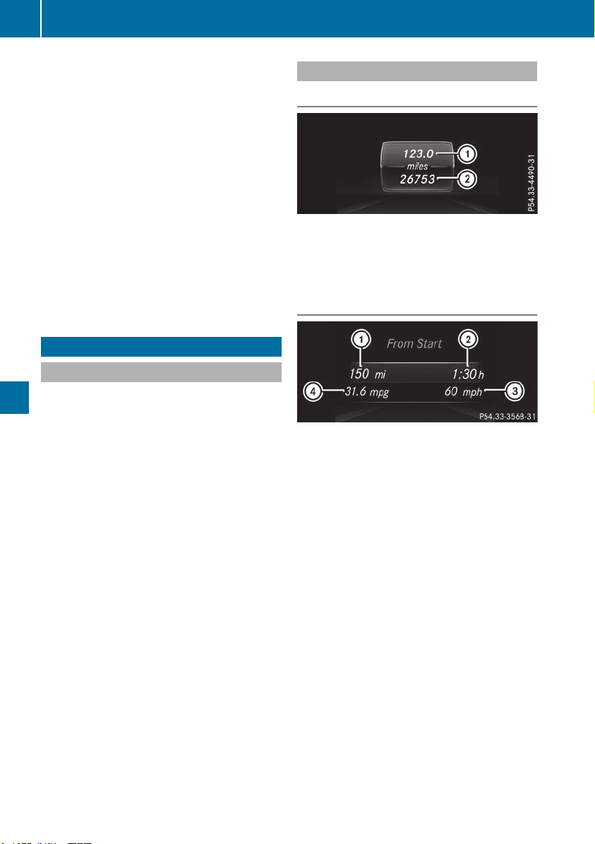
i
Set the time using the multimedia system;
see the Digital Operator's Manual.
Possible displays in the multifunction dis-
play:
R
Z Gearshift recommendation, when shifting
manually (Y page 147)
R
j Active Parking Assist (Y page 191)
R
CRUISECRUISE Cruise control (Y page 169)
R
_ Adaptive Highbeam Assist
(Y page 114)
R
è ECO start/stop function (Y page 139)
R
ë HOLD function (Y page 182)
R
a Active Distance Assist DISTRONIC
Active Steering Assist (Y page 237)
R
DSRDSR Downhill Speed Regulation
(Y page 214)
Menus and submenus
Menu overview
Press the = or ; button on the steering
wheel to call up the menu bar and select a menu.
Operating the on-board computer (Y page 230).
Depending on the equipment installed in the
vehicle, you can call up the following menus:
R
TripTrip menu (Y page 232)
R
NaviNavi menu (navigation instructions)
(Y page 233)
R
AudioAudio menu (Y page 235)
R
TelTel menu (telephone) (Y page 236)
R
DriveAssistDriveAssist menu (assistance)
(Y page 237)
R
Serv.Serv. menu (Y page 238)
R
Sett.Sett. menu (settings) (Y page 239)
R
ON&OFFROADON&OFFROAD menu (Y page 241)
R
AMGAMG menu (Mercedes-AMG vehicles)
(Y page 241)
Trip menu
Standard display
X
Press and hold the % button on the steer-
ing wheel until the TripTrip menu with trip odom-
eter : and odometer ; appears.
Trip computer "From Start" or "From
Reset"
:
Distance
;
Driving time
=
Average speed
?
Average fuel consumption
X
Press the = or ; button on the steering
wheel to select the TripTrip menu.
X
Press the 9 or : button to select
From startFrom start or From resetFrom reset.
The values in the FromFrom StartStart submenu are cal-
culated from the start of a journey, while the
values in the From ResetFrom Reset submenu are calcu-
lated from the last time the submenu was reset
(Y page 233).
The From StartFrom Start trip computer is automatically
reset if:
R
the ignition has been switched off for more
than four hours.
R
999 hours have been exceeded.
R
9,999 miles have been exceeded.
The From resetFrom reset trip computer is automatically
reset if the value exceeds 9,999 hours or
99,999 miles.
232
Menus and submenus
On-board computer and displays
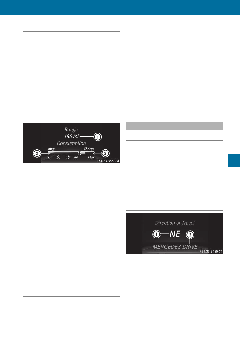
ECO display
The ECO display is not available for Mercedes-
AMG vehicles.
X
Press the = or ; button on the steering
wheel to select the TripTrip menu.
X
Press the 9 or : button to select ECOECO
DISPLAYDISPLAY.
If the ignition remains switched off for longer
than four hours, the ECO display will be auto-
matically reset.
For more information on the ECO display, see
(Y page 160).
Displaying the range and current fuel
consumption
Mercedes-AMG vehicles: the menu displays
only the approximate range :.
X
Press the = or ; button on the steering
wheel to select the TripTrip menu.
Digital speedometer
X
Press the = or ; button on the steering
wheel to select the TripTrip menu.
X
Press the 9 or : button to select the
digital speedometer.
A gear shift recommendation Z can also
appear.
Observe the information on gearshift recom-
mendation Z when shifting manually
(Y page 147).
Mercedes-AMG vehicles: a gearshift recom-
mendation is shown in the status bar of the
multifunction display and not in the digital
speedometer display.
Resetting values
X
Press the = or ; button on the steering
wheel to select the TripTrip menu.
X
Press the 9 or : button to select the
function that you wish to reset.
X
Press a to confirm your selection.
X
Press : to select YesYes and press a to
confirm.
You can reset the values of the following func-
tions:
R
Trip odometer
R
"From Start" trip computer
R
"From Reset" trip computer
R
ECO display
If you reset the values in the ECO display, the
values in the "From Start" trip computer are also
reset. If you reset the values in the "From Start"
trip computer, the values in the ECO display are
also reset.
Navigation system menu
Displaying navigation instructions
In the NaviNavi menu, the multifunction display
shows navigation instructions.
You can find further information on navigation in
the Digital Operator's Manual in the multimedia
system.
X
Switch on the multimedia system (see the
Digital Operator's Manual)
X
Press the = or ; button on the steering
wheel to select the NaviNavi menu.
Route guidance not active
:
Direction of travel
;
Current road
Menus and submenus
233
On-board computer and displays
Z
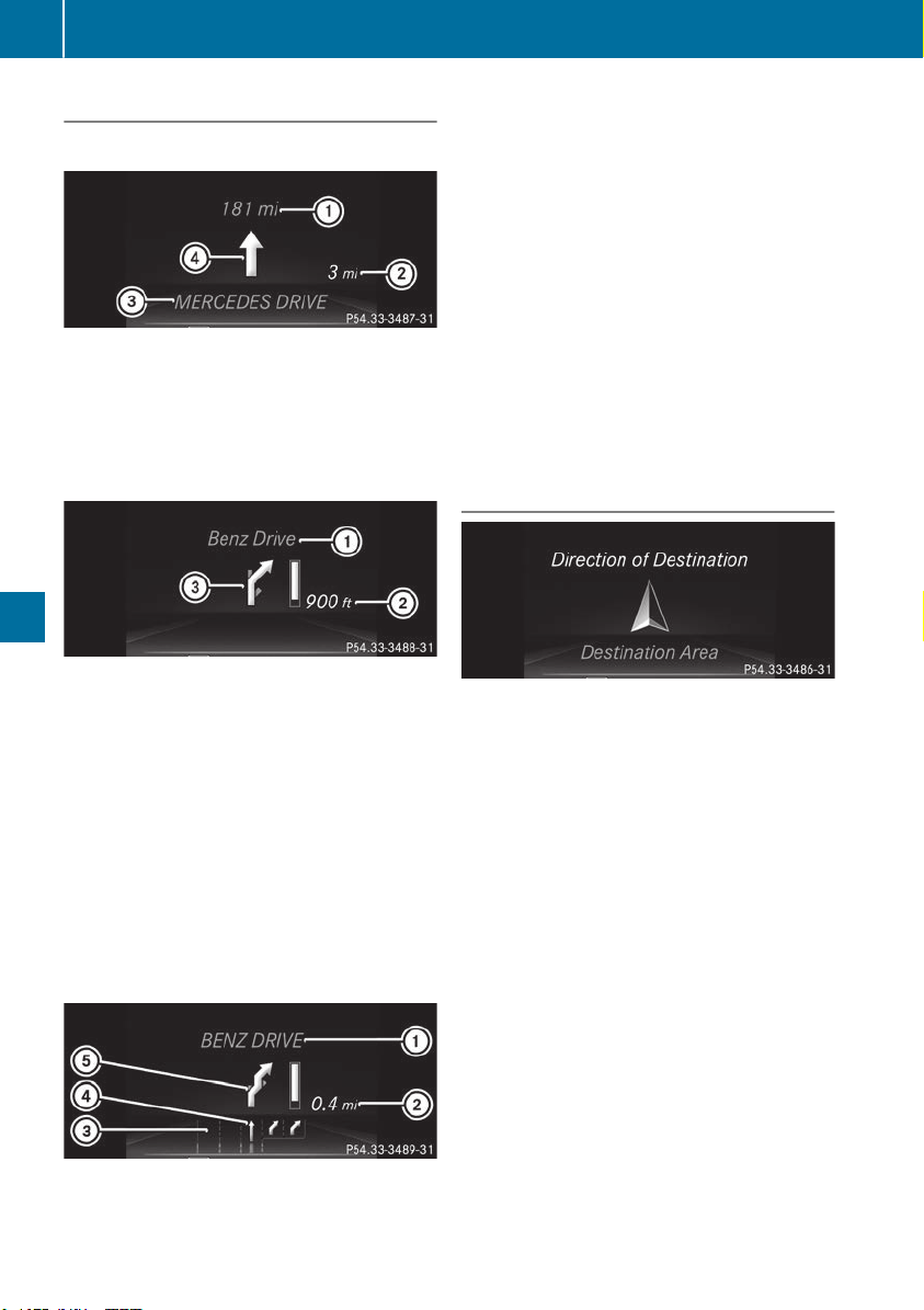
Route guidance active
No change of direction announced
:
Distance to destination
;
Distance to the next change of direction
=
Current road
?
"Follow the road's course" symbol
Change of direction announced without a
lane recommendation
:
Road into which the change of direction
leads
;
Distance to change of direction and visual
distance display
=
Change-of-direction symbol
When a change of direction is to be made, you
will see symbol = for the change of direction
and distance graphic ;. The distance indicator
shortens towards the top of the display as you
approach the point of the announced change of
direction. The change of direction starts once
the distance display reaches zero.
Change of direction announced with a
lane recommendation
:
Road into which the change of direction
leads
;
Distance to change of direction and visual
distance display
=
Lanes not recommended
?
Recommended lane and new lane during a
change of direction
A
Change-of-direction symbol
On multilane roads, lane recommendations can
be displayed for the next change of direction if
the digital map supports this data. During the
change of direction, new lanes may be added.
Lane not recommended =: you will not be able
to complete the next change of direction if you
stay in this lane.
Recommended lane and new lane during a
change of direction ?: in this lane you will be
able to complete the next two changes of direc-
tion without changing lane.
Other status indicators of the naviga-
tion system
The navigation system displays additional infor-
mation and the vehicle status.
Possible displays:
R
New Route...New Route... or Calculating Route...Calculating Route...
A new route is calculated.
R
Road Not MappedRoad Not Mapped
The vehicle position is inside the area of the
digital map but the road is not recognized, e.g.
newly built streets, car parks or private land.
R
No RouteNo Route
No route could be calculated to the selected
destination.
R
O
You have reached the destination or an inter-
mediate destination.
234
Menus and submenus
On-board computer and displays
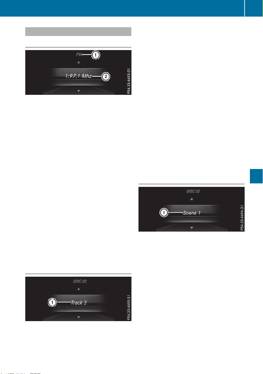
Audio menu
Selecting a radio station
:
Active station list
;
Station frequency with memory position
The multifunction display shows station ; with
station frequency or station name. The preset
position is only displayed along with station ; if
this has been stored. You can store TV chan-
nels ; in the multimedia system.
X
Switch on the multimedia system and select
radio (see the Digital Operator's Manual).
X
Press the = or ; button on the steering
wheel to select the AudioAudio menu.
X
To select a preset list or station list: press
and briefly hold the 9 or : button until
the preset list or station list in the desired
frequency range is shown in the multifunction
display.
X
To select a station: briefly press 9
or :.
i
SIRIUS XM satellite radio functions like a
normal radio.
For more information on radio operation, see
"Satellite radio" in the Digital Operator's Man-
ual.
Operating an audio player or audio
media
Audio files from various audio players or media
can be played, depending on the equipment
installed in the vehicle.
X
Switch on the multimedia system and select
CD or MP3 mode (see the Digital Operator's
Manual).
X
Press the = or ; button on the steering
wheel to select the AudioAudio menu.
X
To select the next/previous track: briefly
press the 9 or : button.
X
To select a track from the track list (rapid
scrolling): press and hold the 9 or :
button until desired track : has been
reached.
If you press and hold 9 or :, the rapid
scrolling speed is increased. Not all audio
players or media support this function.
If track information is saved on the audio player
or media, the multifunction display will show the
number and title of the track. The current track
does not appear in audio mode (Auxiliary audio
mode: external audio source connected).
Video DVD operation
X
Switch on the multimedia system and select
video DVD (see the Digital Operator's Man-
ual).
X
Press the = or ; button on the steering
wheel to select the AudioAudio menu.
X
To select the next or previous scene:
briefly press the 9 or : button.
X
To select a scene from the scene list
(rapid scrolling): press and hold the 9
or : button until desired scene : has
been reached.
Menus and submenus
235
On-board computer and displays
Z

Telephone menu
Introduction
G
WARNING
If you operate information systems and com-
munication equipment integrated in the vehi-
cle when driving, you may be distracted from
the traffic situation. You could also lose con-
trol of the vehicle. There is a risk of an acci-
dent.
Only operate this equipment when the traffic
situation permits. If you are not sure that this
is possible, park the vehicle paying attention
to traffic conditions and operate the equip-
ment when the vehicle is stationary.
When telephoning, you must observe the legal
requirements for the country in which you are
currently driving.
X
Switch on the mobile phone (see the manu-
facturer’s operating instructions).
X
Switch on the multimedia system (see the
Digital Operator's Manual)
X
Establish a Bluetooth
®
connection to the mul-
timedia system (see the Digital Operator's
Manual).
X
Press the = or ; button on the steering
wheel to select the TelTel menu.
You will see one of the following display mes-
sages in the multifunction display:
R
Phone READYPhone READY or the name of the network
provider: the mobile phone has found a net-
work and is ready to receive.
R
Phone No ServicePhone No Service: there is no network
available or the mobile phone is searching for
a network.
Accepting a call
If someone calls you when you are in the TelTel
menu, a display message appears in the multi-
function display.
You can accept a call at any time regardless of
the menu selected.
X
Press the 6 button on the steering wheel
to accept an incoming call.
Rejecting or ending a call
You can end or reject a call even if you are not in
the TelTel menu.
X
Press the ~ button on the steering wheel
to reject or end a call.
Selecting an entry from the phone book
X
Press the = or ; button on the steering
wheel to select the TelTel menu.
X
Press the 9, : or a button to
switch to the phone book.
X
Authorize access to the phone book on the
phone.
X
Press the 9 or : button to select the
desired name.
or
X
To start rapid scrolling: press and hold the
9 or : button for longer than one sec-
ond.
Rapid scrolling stops when you release the
button or reach the end of the list.
X
If only one telephone number is stored for
a name: press the 6 or a button to
start dialing.
or
X
If there is more than one number for a
particular name: press the 6 or a
button to display the numbers.
X
Press the 9 or : button to select the
number you want to dial.
X
Press the 6 or a button to start dialing.
or
X
To exit the telephone book: press the ~
or % button.
Redialing
The on-board computer saves the last names or
numbers dialed in the redial memory.
X
Press the = or ; button on the steering
wheel to select the TelTel menu.
X
Press the 6 button to switch to the redial
memory.
X
Press the 9 or : button to select the
desired name or number.
236
Menus and submenus
On-board computer and displays
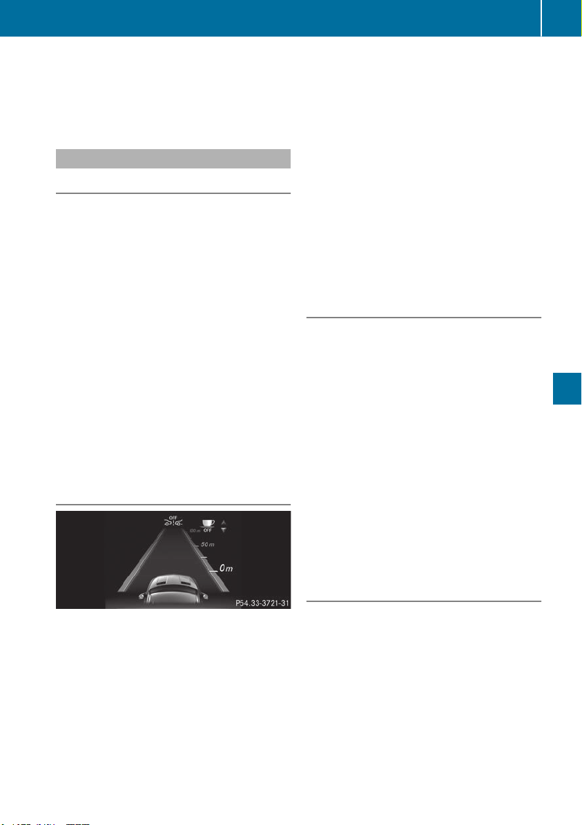
X
Press the 6 or a button to start dialing.
or
X
To exit the redial memory: press the ~
or % button.
Assistance menu
Introduction
Depending on the equipment installed in the
vehicle, you have the following options in the
DriveAssistDriveAssist menu:
R
Displaying the assistance graphic
(Y page 237)
R
Activating/deactivating the Traffic Sign
Assist display (Y page 237)
R
Activating or deactivating Active Steering
Assist (Y page 237)
R
Activating/deactivating Active Brake Assist
(Y page 238)
R
Activating/deactivating Active Brake Assist
with cross-traffic function (Y page 238)
R
Activating/deactivating ATTENTION ASSIST
(Y page 238)
R
Activating/deactivating Blind Spot Assist or
Active Blind Spot Assist (Y page 238)
R
Activating/deactivating Lane Keeping Assist
or Active Lane Keeping Assist (Y page 238)
Displaying the assistance graphic
X
Press the = or ; button on the steering
wheel to select the DriveAssistDriveAssist menu.
X
Press 9 or : to select AssistanceAssistance
GraphicGraphic.
X
Confirm by pressing a on the steering
wheel.
The multifunction display shows the Active
Distance Assist DISTRONIC distance display
on the assistant display.
The assistance graphic displays the status of
and information from the following driving
systems or driving safety systems:
R
Traffic Sign Assist (Y page 205)
R
Active Distance Assist DISTRONIC
(Y page 171)
R
Active Brake Assist (Y page 67)
R
Active Brake Assist with cross-traffic func-
tion (Y page 73)
R
ATTENTION ASSIST (Y page 203)
R
Lane Keeping Assist (Y page 207) or Active
Lane Keeping Assist (Y page 211)
R
DSR (Y page 214)
R
Off-road program (vehicles with Off-Road
Engineering package) (Y page 216)
R
Rear window wipers (Y page 118)
X
Press : to display the ATTENTION ASSIST
assessment.
Traffic Sign Assist
You can switch the Traffic Sign Assist message
function on or off in the TrafficTraffic SignSign AssistAssist
menu. When the function is activated, detected
traffic signs and information appear in the mul-
tifunction display for five seconds.
X
Press the = or ; button on the steering
wheel to select the DriveAssistDriveAssist menu.
X
Press the 9 or : button to select
Traffic Sign AssistTraffic Sign Assist.
X
Confirm by pressing a on the steering
wheel.
The current selection appears.
X
To activate/deactivate the message func-
tion: press the a button again.
For further information about Traffic Sign Assist,
see (Y page 205).
Activating or deactivating Active Steer-
ing Assist
X
Press the = or ; button on the steering
wheel to select the DriveAssistDriveAssist menu.
X
Press the 9 or : button to select
Active Steering AssistActive Steering Assist.
X
Confirm by pressing a on the steering
wheel.
The current selection appears.
X
To activate/deactivate: press the a but-
ton again.
When Active Steering Assist is activated, the
multifunction display shows the ActiveActive
Steering AssistSteering Assist OnOn message.
Menus and submenus
237
On-board computer and displays
Z

Further information about Active Distance
Assist DISTRONIC with Active Steering Assist
(Y page 177).
Activating/deactivating Active Brake
Assist
You can use these functions to activate/deac-
tivate Active Brake Assist or, on vehicles with
the Driving Assistance package, to activate or
deactivate Active Brake Assist with cross-traffic
function.
X
Press the = or ; button on the steering
wheel to select the DriveAssistDriveAssist menu.
X
Press the 9 or : button to select
Brake AssistBrake Assist.
X
Press a to confirm.
The current selection appears.
X
To activate/deactivate: press the a but-
ton again.
When Active Brake Assist or Active Brake
Assist with cross-traffic function is deactiva-
ted, the æ symbol appears in the multi-
function display in the assistance graphic dis-
play.
Further information on Active Brake Assist
(Y page 67)and Active Brake Assist with cross-
traffic function (Y page 72).
Activating/deactivating ATTENTION
ASSIST
X
Press the = or ; button on the steering
wheel to select the DriveAssistDriveAssist menu.
X
Press the 9 or : button to select
Attention AssistAttention Assist.
X
Press the a button.
The current selection appears.
X
Press a to confirm.
X
Press the : or 9 button to set OffOff,
StandardStandard or SensitiveSensitive.
X
Press the a button to save the setting.
When ATTENTION ASSIST is deactivated, the
é symbol appears in the multifunction dis-
play in the assistance graphics display.
For further information about ATTENTION
ASSIST, see (Y page 203).
Activating/deactivating Blind Spot
Assist
X
Press the = or ; button on the steering
wheel to select the DriveAssistDriveAssist menu.
X
Press the 9 or : button to select
Blind Spot AssistBlind Spot Assist.
X
Confirm by pressing a on the steering
wheel.
The current selection appears.
X
To activate/deactivate: press the a but-
ton again.
For further information about Blind Spot Assist,
see (Y page 206).
For further information about Active Blind Spot
Assist, see (Y page 209).
Activating/deactivating Lane Keeping
Assist
X
Press the = or ; button on the steering
wheel to select the DriveAssistDriveAssist menu.
X
Press the 9 or : button to select
Lane Keeping AssistLane Keeping Assist.
X
Press a to confirm.
The current selection appears.
X
Press a to confirm.
X
Press the : or 9 button to set OffOff,
StandardStandard or AdaptiveAdaptive.
When Lane Keeping Assist or Active Lane
Keeping Assist is activated, the multifunction
display shows the lane markings as bright
lines in the assistance graphic.
X
Press the a button to save the setting.
For further information about Lane Keeping
Assist, see (Y page 207).
For further information about Active Lane Keep-
ing Assist, see (Y page 211).
Service menu
Introduction
Depending on the equipment installed in the
vehicle, you have the following options in the
Serv.Serv. menu:
238
Menus and submenus
On-board computer and displays

R
calling up display messages in message mem-
ory (Y page 244)
R
restarting the tire pressure loss warning sys-
tem (Y page 358) or checking the tire pres-
sure electronically (Y page 360)
R
calling up the service due date (Y page 325).
Settings menu
Introduction
Depending on the equipment installed in the
vehicle, In the Sett.Sett. menu you have the follow-
ing options:
R
Changing the instrument cluster settings
(Y page 239)
R
Changing the light settings (Y page 239)
R
Changing the vehicle settings (Y page 240)
R
Changing the convenience settings
(Y page 240)
R
Restoring the factory settings (Y page 241)
Instrument cluster submenu
Selecting the distance unit
The Display Unit Speedometer / Odome‐Display Unit Speedometer / Odome‐
ter:ter: function allows you to choose whether
certain displays appear in kilometers or miles in
the multifunction display.
X
Press the = or ; button on the steering
wheel to select the Sett.Sett. menu.
X
Press the : or 9 button to select the
Instrument ClusterInstrument Cluster submenu.
X
Press a to confirm.
X
Press the : or 9 button to select the
Display Unit Speedometer / OdometerDisplay Unit Speedometer / Odometer
function.
You will see the selected setting: kmkm or milesmiles.
X
Press the a button to save the setting.
The selected unit of measurement for distance
applies to:
R
Digital speedometer in the TripTrip menu
R
Odometer and the trip odometer
R
Trip computer
R
Current consumption and the range
R
Navigation instructions in the NaviNavi menu
R
Cruise control
R
Active Distance Assist DISTRONIC
R
ASSYST PLUS service interval display
Selecting permanent display
The Permanent Display:Permanent Display: function allows you
to choose whether the multifunction display
always shows the outside temperature or the
speed.
The speed display is inverse to the speedome-
ter.
X
Press the = or ; button on the steering
wheel to select the Sett.Sett. menu.
X
Press the : or 9 button to select the
Instrument ClusterInstrument Cluster submenu.
X
Confirm by pressing a on the steering
wheel.
X
Press the : or 9 button to select the
Permanent Display:Permanent Display: function.
The current setting, Outside TemperatureOutside Temperature,
Speedometer [km/h]Speedometer [km/h] or SpeedometerSpeedometer
[mph][mph] appears.
X
To change the setting: press a again.
Light submenu
Setting the daytime running lamps
This function is not available in Canada.
X
Press the = or ; button on the steering
wheel to select the Sett.Sett. menu.
X
Press the : or 9 button to select the
LightLight submenu.
X
Press a to confirm.
X
Press : or 9 to select the DaytimeDaytime
Running LightsRunning Lights function.
If the DaytimeDaytime RunningRunning LightsLights function has
been switched on, the cone of light and the
W symbol in the multifunction display are
shown in orange.
X
Press the a button to save the setting.
Further information on daytime running lamps
(Y page 110).
Switching the Intelligent Light System
on/off
X
Press the = or ; button on the steering
wheel to select the Sett.Sett. menu.
X
Press the : or 9 button to select the
LightLight submenu.
X
Press a to confirm.
Menus and submenus
239
On-board computer and displays
Z

X
Press the : or 9 button to select the
Intell. Light SystemIntell. Light System function.
If the Intell. Light SystemIntell. Light System function has
been switched on, the cone of light and the
L symbol in the multifunction display are
shown in orange.
X
Press the a button to save the setting.
When you activate Intell. Light SystemIntell. Light System,
you activate the following functions:
R
Highway mode
R
Active light function
R
Cornering light function
R
Extended range fog lamps
R
Off-road lights
Further information on the Intelligent Light Sys-
tem (Y page 112).
Vehicle submenu
Activating/deactivating the automatic
door locking mechanism
If you activate the AutomaticAutomatic DoorDoor LockLock func-
tion, the vehicle is centrally locked above a
speed of approximately 9 mph (15 km/h).
X
Press the = or ; button on the steering
wheel to select the Sett.Sett. menu.
X
Press the : or 9 button to select the
VehicleVehicle submenu.
X
Press a to confirm.
X
Press the : or 9 button to select the
Automatic Door LockAutomatic Door Lock function.
When the Automatic Door LockAutomatic Door Lock function is
activated, the vehicle doors are displayed in
orange in the multifunction display.
X
Press the a button to save the setting.
For further information on the automatic locking
feature, see (Y page 84).
Activating/deactivating the acoustic
locking verification signal
If you switch on the AcousticAcoustic LockLock function, an
acoustic signal sounds when you lock the vehi-
cle.
X
Press the = or ; button on the steering
wheel to select the SettingsSettings menu.
X
Press the : or 9 button to select the
VehicleVehicle submenu.
X
Press a to confirm.
X
Press the : or 9 button to select the
Acoustic LockAcoustic Lock function.
If the Acoustic LockAcoustic Lock function is activated,
the & symbol in the multifunction display
lights up orange.
X
Press the a button to save the setting.
Convenience submenu
Activating/deactivating the EASY-
ENTRY/EXIT feature
G
WARNING
When the EASY-ENTRY/EXIT feature adjusts
the steering wheel, you and other vehicle
occupants – particularly children – could
become trapped. There is a risk of injury.
While the EASY-ENTRY/EXIT feature is mak-
ing adjustments, make sure that no one has
any body parts in the sweep of the steering
wheel.
If somebody becomes trapped:
R
press one of the memory function position
buttons, or
R
move the switch for steering wheel adjust-
ment in the opposite direction to that in
which the steering wheel is moving.
The adjustment process is stopped.
X
Press the = or ; button on the steering
wheel to select the Sett.Sett. menu.
X
Press the : or 9 button to select the
ConvenienceConvenience submenu.
X
Press a to confirm.
X
Using : or 9, select the EasyEasy Entry/Entry/
ExitExit function.
If the EasyEasy Entry/ExitEntry/Exit function is activated,
the vehicle steering wheel is displayed in
orange in the multifunction display.
X
Press the a button to save the setting.
Further information on the EASY-ENTRY/EXIT
feature (Y page 104).
Switching the seat belt adjustment on/off
X
Press the = or ; button on the steering
wheel to select the SettingsSettings menu.
X
Press the : or 9 button to select the
ConvenienceConvenience submenu.
X
Press a to confirm.
240
Menus and submenus
On-board computer and displays
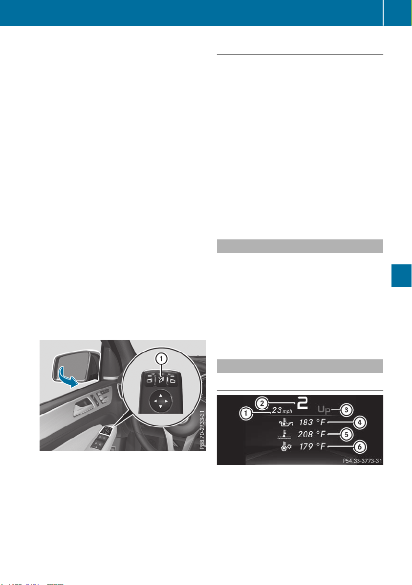
X
Press the : or 9 button to select the
Belt AdjustmentBelt Adjustment function.
If the BeltBelt AdjustmentAdjustment function is activated,
the vehicle seat belt is shown in orange in the
multifunction display.
X
Press the a button to save the setting.
For further information on belt adjustment, see
(Y page 48).
Switching the fold-in mirrors when lock-
ing feature on/off
This function is only available when the vehicle is
equipped with the electrical fold-in function.
When you activate the Auto.Auto. MirrorMirror FoldingFolding
function, the exterior mirrors are folded in when
the vehicle is locked. The exterior mirrors fold
out automatically again as soon as you unlock
the vehicle.
X
Press the = or ; button on the steering
wheel to select the Sett.Sett. menu.
X
Press the : or 9 button to select the
ConvenienceConvenience submenu.
X
Press a to confirm.
X
Press the : or 9 button to select the
Auto. Mirror FoldingAuto. Mirror Folding function.
If the Auto. Mirror FoldingAuto. Mirror Folding function is
switched on, the multifunction display shows
the exterior mirror in orange.
X
Press the a button to save the setting.
If you have switched the Auto. Mirror Fold‐Auto. Mirror Fold‐
inging on and you fold the exterior mirrors in using
button :, they will not fold out automatically
(Y page 106).
You can then only fold out the exterior mirrors
using button :.
Restoring the factory settings
X
Press the = or ; button on the steering
wheel to select the Sett.Sett. menu.
X
Press the : or 9 button to select the
Factory SettingFactory Setting submenu.
X
Press a to confirm.
The Reset All Settings?Reset All Settings? message
appears.
X
Press the : or 9 button to select NoNo or
YesYes.
X
Press a to confirm the selection.
If you select YesYes, the multifunction display
shows a confirmation message.
If you want to reset the Daytime RunningDaytime Running
LightsLights function in the LightLight submenu, you
must turn the SmartKey to position 1 in the
ignition lock.
ON&OFFROAD menu
X
Press the = or ; button on the steering
wheel to select the ON&OFFROADON&OFFROAD menu.
You can view the current off-road program set-
tings in the ON&OFFROADON&OFFROAD menu:
R
Vehicles with the Off-Road Engineering pack-
age (Y page 216)
R
Vehicles without the Offroad Engineering
package (Y page 215)
AMG menu (Mercedes-AMG vehicles)
Warm-up
:
Digital speedometer
;
Gear indicator
=
Upshift indicator
?
Engine oil temperature
A
Coolant temperature
B
Transmission oil temperature
Menus and submenus
241
On-board computer and displays
Z
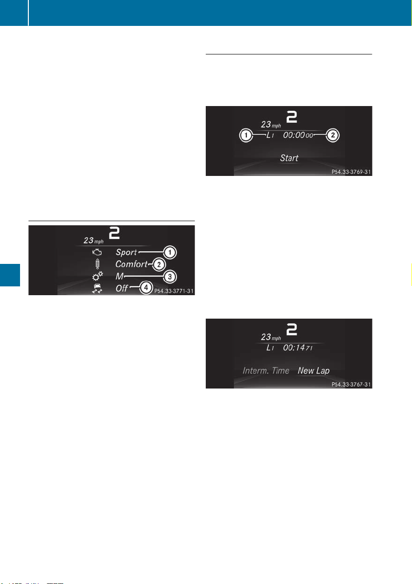
X
Press the = or ; button on the steering
wheel to select the AMGAMG menu.
Upshift indicator: upshift indicator UpUp =
indicates that the engine has reached the
overrevving range when in the manual drive
program.
Engine/transmission oil temperature:
when the engine and transmission are at nor-
mal operating temperature, oil tempera-
ture ? and B are displayed in white in the
multifunction display.
If the multifunction display shows oil temper-
ature ? or B in blue, the engine or the
transmission are not yet at normal operating
temperature. Avoid driving at full engine out-
put during this time.
SETUP
:
Engine mode (ComfortComfort/SportSport/Sport +Sport +)
;
Suspension setting ComfortComfort/SportSport/
Sport +Sport +
=
Transmission position DD/MM
?
ESP
®
mode (ONON/OFFOFF)
SETUP displays the following information/func-
tions:
R
the digital speedometer
R
the gear indicator
R
the engine mode
R
the suspension mode
R
the transmission position
R
the ESP
®
(Electronic Stability Program) mode
X
Press the = or ; button on the steering
wheel to select the AMGAMG menu.
X
Press the 9 button repeatedly until SETUP
is displayed.
RACE TIMER
Displaying and starting RACETIMER
The RACETIMER is only intended for use on a
closed race circuit. Do not use the function on
public roads.
:
Lap
;
RACETIMER
You can start the RACETIMER when the engine is
running or if the SmartKey is in position 2 in the
ignition lock.
X
Press the = or ; button on the steering
wheel to select the AMGAMG menu.
X
Press the 9 button repeatedly until the
RACETIMER is shown.
X
To start: press the a button to start the
RACETIMER.
Displaying the intermediate time
X
Press the = or ; button to select
Interm. TimeInterm. Time.
X
Press a to confirm.
The intermediate time is displayed for five
seconds.
242
Menus and submenus
On-board computer and displays
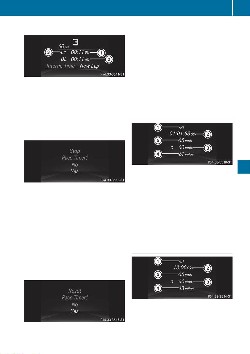
Starting a new lap
:
RACETIMER
;
Fastest lap time (best lap)
=
Lap
X
Press a to confirm New LapNew Lap.
i
It is possible to store a maximum of sixteen
laps. The 16th lap can only be completed with
Finish LapFinish Lap.
Stopping the RACETIMER
X
Press the % button on the steering wheel.
X
Confirm YesYes with a.
The RACETIMER interrupts timing if you stop the
vehicle and turn the SmartKey to position 1 in
the ignition lock. If you turn the SmartKey to
position 3 and then press a to confirm
StartStart timing is continued.
Resetting the current lap
X
Stop the RACETIMER.
X
Press the = or ; button to select
Reset LapReset Lap.
X
Press a to reset the lap time to "0".
Deleting all laps
If you switch off the engine, the RACETIMER is
reset to "0" after 30 seconds. All laps are
deleted.
You cannot delete individual stored laps. If you
have stopped 16 laps, the current lap does not
have to be reset.
X
Reset the current lap.
X
Press a to confirm ResetReset.
Reset Race Timer?Reset Race Timer? appears in the multi-
function display.
X
Press the : button to select YesYes and press
the a button to confirm.
All laps are deleted.
Overall statistics
:
RACETIMER overall evaluation
;
Total time driven
=
Average speed
?
Distance covered
A
Maximum speed
This function is shown if you have stored at least
one lap and stopped the RACETIMER.
X
Press the = or ; button on the steering
wheel to select the AMGAMG menu.
X
Press the 9 button repeatedly until the
overall evaluation is shown.
Lap statistics
:
Lap
;
Lap time
=
Average lap speed
?
Lap length
A
Top speed during lap
Menus and submenus
243
On-board computer and displays
Z

This function is only available if you have stored
at least two laps and have stopped the RACE-
TIMER.
X
Press the = or ; button on the steering
wheel to select the AMGAMG menu.
X
Press the 9 button repeatedly until the lap
evaluation is shown.
Each lap is shown in a separate submenu. The
fastest lap is indicated by flashing symbol :.
X
Press the 9 or : button to select a dif-
ferent lap evaluation.
Display messages
Introduction
General notes
Display messages appear in the multifunction display.
Display messages with graphic displays may be shown in simplified form in the Operator's Manual
and may therefore differ from the multifunction display.
Please respond in accordance with the display messages and follow the additional notes in this
Operator's Manual.
Certain display messages are accompanied by an audible warning tone or a continuous tone.
When you stop and park the vehicle, please observe the notes on:
R
HOLD function (Y page 182)
R
Parking (Y page 156)
Hiding display messages
X
Press the a or % button on the steering wheel.
The multifunction display hides the display message.
High-priority display messages are shown in red in the multifunction display. Some high-priority
display messages cannot be hidden.
The multifunction display shows these messages continuously until the causes for the messages
have been remedied.
Message memory
The on-board computer saves certain display messages in the message memory. You can call up
the display messages:
X
Press = or ; on the steering wheel to select the Serv.Serv. menu.
If there are display messages, the multifunction display shows 2 Messages2 Messages, for example.
X
Press the 9 or : button to select the entry, e.g. 2 messages2 messages.
X
Press a to confirm.
X
Press the 9 or : button to scroll through the display messages.
When the ignition is switched off, all display messages are deleted, apart from some high-priority
display messages. Once the causes of the high-priority display messages have been rectified, the
corresponding display messages are also deleted.
244
Display messages
On-board computer and displays

Safety systems
Display messages
Possible causes/consequences and MM Solutions
!÷
Currently Unavaila‐Currently Unavaila‐
ble See Operator'sble See Operator's
ManualManual
ABS (Anti-lock Braking System) and ESP
®
(Electronic Stability Pro-
gram) are temporarily not available.
Other driving systems and driving safety systems may also malfunc-
tion.
In addition, the ÷, å and ! warning lamps light up in the
instrument cluster.
Possible causes are:
R
Self-diagnosis is not yet complete
R
The on-board voltage may be insufficient
G
WARNING
The brake system continues to function normally, but without the
functions listed above. The wheels could therefore lock if you brake
hard, for example.
The steerability and braking characteristics may be severely affected.
The braking distance in an emergency braking situation can increase.
If ESP
®
is not operational, ESP
®
is unable to stabilize the vehicle.
There is an increased risk of skidding and an accident.
X
Carefully drive a suitable distance, making slight steering move-
ments at a speed above 12 mph (20 km/h).
If the display message disappears, the functions mentioned above
are available again.
If the multifunction display still shows the display message:
X
Drive on carefully.
X
Visit a qualified specialist workshop immediately.
!÷
Inoperative SeeInoperative See
Operator's ManualOperator's Manual
ABS and ESP
®
are malfunctioning.
Other driving systems and driving safety systems may also malfunc-
tion.
The $ (USA only) or J (Canada only), ÷, å and !
warning lamps in the instrument cluster also light up.
G
WARNING
The brake system continues to function normally, but without the
functions listed above. The wheels could therefore lock if you brake
hard, for example.
The steerability and braking characteristics may be severely affected.
The braking distance in an emergency braking situation can increase.
If ESP
®
is not operational, ESP
®
is unable to stabilize the vehicle.
There is an increased risk of skidding and an accident.
X
Drive on carefully.
X
Visit a qualified specialist workshop immediately.
Display messages
245
On-board computer and displays
Z

Display messages
Possible causes/consequences and MM Solutions
÷
Currently Unavaila‐Currently Unavaila‐
ble See Operator'sble See Operator's
ManualManual
ESP
®
is temporarily unavailable.
Other driving systems and driving safety systems may also malfunc-
tion.
In addition, the ÷ and å warning lamps light up in the instru-
ment cluster.
The self-diagnosis function might not be complete, for example.
ATTENTION ASSIST is deactivated.
G
WARNING
The brake system continues to function normally, but without the
functions listed above. The wheels could therefore lock if you brake
hard, for example.
The braking distance in an emergency braking situation can thus
increase.
If ESP
®
is not operational, ESP
®
is unable to stabilize the vehicle.
There is an increased risk of skidding and an accident.
X
Carefully drive a suitable distance, making slight steering move-
ments at a speed above 12 mph (20 km/h).
If the display message disappears, the functions mentioned above
are available again.
If the multifunction display still shows the display message:
X
Drive on carefully.
X
Visit a qualified specialist workshop immediately.
÷
Inoperative SeeInoperative See
Operator's ManualOperator's Manual
ESP
®
is malfunctioning.
Other driving systems and driving safety systems may also malfunc-
tion.
In addition, the ÷ and å warning lamps light up in the instru-
ment cluster.
G
WARNING
The brake system continues to function normally, but without the
functions listed above. The wheels could therefore lock if you brake
hard, for example.
The braking distance in an emergency braking situation can thus
increase.
If ESP
®
is not operational, ESP
®
is unable to stabilize the vehicle.
There is an increased risk of skidding and an accident.
X
Drive on carefully.
X
Visit a qualified specialist workshop immediately.
246
Display messages
On-board computer and displays

Display messages
Possible causes/consequences and MM Solutions
T !
÷
Inoperative SeeInoperative See
Operator's ManualOperator's Manual
EBD (electronic brake force distribution), ABS and ESP
®
are malfunc-
tioning.
Other driving systems and driving safety systems may also malfunc-
tion.
In addition, the ÷, å and ! warning lamps light up in the
instrument cluster and a warning tone sounds.
G
WARNING
The brake system continues to function normally, but without the
functions listed above. The wheels could therefore lock if you brake
hard, for example.
The steerability and braking characteristics may be severely affected.
The braking distance in an emergency braking situation can increase.
If ESP
®
is not operational, ESP
®
is unable to stabilize the vehicle.
There is an increased risk of skidding and an accident.
X
Drive on carefully.
X
Visit a qualified specialist workshop immediately.
F (USA
only) ! (Canada
only)
Turn On the Igni‐Turn On the Igni‐
tiontion toto ReleaseRelease thethe
Parking BrakeParking Brake
The red F (USA only) or ! (Canada only) indicator lamp lights
up.
You attempted to release the electric parking brake while the ignition
was switched off.
X
SmartKey : insert the SmartKey into the ignition lock and turn to
position 1.
X
KEYLESS-GO: switch on the ignition.
F (USA
only) ! (Canada
only)
PleasePlease ReleaseRelease Park‐Park‐
ing Brakeing Brake
The red F (USA only) or ! (Canada only) indicator lamp flashes
and a warning tone sounds. A condition for automatic release of the
electric parking brake is not fulfilled (Y page 157).
You are driving with the electric parking brake applied.
X
Release the electric parking brake manually.
The red F (USA only) or ! (Canada only) indicator lamp flashes
and a warning tone sounds.
You are using the electric parking brake for emergency braking
(Y page 157).
F (USA
only) ! (Canada
only)
Parking Brake SeeParking Brake See
Operator's ManualOperator's Manual
The yellow ! warning lamp lights up.
The electric parking brake is malfunctioning.
To apply:
X
Switch the ignition off.
X
Press the electric parking brake handle for at least ten seconds.
X
Shift the transmission to position j .
X
Consult a qualified specialist workshop.
Display messages
247
On-board computer and displays
Z

Display messages
Possible causes/consequences and MM Solutions
The yellow ! warning lamp and the red F (USA only) or !
(Canada only) indicator lamp light up.
The electric parking brake is malfunctioning.
To release:
X
Switch off the ignition and turn it back on.
X
Release the electric parking brake manually.
or
X
Release the electric parking brake automatically (Y page 157).
If the electric parking brake still cannot be released:
X
Do not drive on.
X
Consult a qualified specialist workshop.
The red F (USA only) or ! (Canada only) indicator lamp flashes
and the yellow ! warning lamp lights up.
The electric parking brake is malfunctioning.
To release:
X
Switch off the ignition and turn it back on.
X
Release the electric parking brake manually.
To apply:
X
Switch off the ignition and turn it back on.
X
Apply the electric parking brake manually.
If the red F (USA only) or ! (Canada only) indicator lamp con-
tinues to flash:
X
Do not drive on.
X
Secure the vehicle against rolling away (Y page 372).
X
Shift the transmission to position j .
X
Turn the front wheels towards the curb.
X
Consult a qualified specialist workshop.
248
Display messages
On-board computer and displays

Display messages
Possible causes/consequences and MM Solutions
The yellow ! warning lamp lights up. The red F (USA only)
or ! (Canada only) indicator lamp flashes for about ten seconds
after the electric parking brake has been applied or released. It then
goes out or remains lit.
The electric parking brake is malfunctioning.
X
Switch off the ignition and turn it back on.
X
Apply the electric parking brake.
If it is not possible to apply the electric parking brake:
X
Shift the transmission to position j.
X
Visit a qualified specialist workshop.
If it is not possible to release the electric parking brake:
X
Release the electric parking brake automatically (Y page 157).
If the electric parking brake still cannot be released:
X
Consult a qualified specialist workshop.
The yellow ! warning lamp lights up. If you manually apply or
release the electric parking brake, the red F (USA only) or !
(Canada only) indicator lamp flashes.
The electric parking brake is malfunctioning. It is not possible to apply
the electric parking brake manually.
X
Shift the transmission to position j .
X
Visit a qualified specialist workshop.
F (USA
only) ! (Canada
only)
Parking Brake Inop‐Parking Brake Inop‐
erativeerative
The yellow ! warning lamp lights up. The red F (USA only)
or ! (Canada only) indicator lamp flashes for about ten seconds
after the electric parking brake has been applied or released. It then
goes out or remains lit.
The electric parking brake is malfunctioning, e.g. because of over-
voltage or undervoltage.
X
Remove the cause for the overvoltage or undervoltage, e.g. by
charging the battery or restarting the engine.
X
Apply or release the electric parking brake.
If it remains impossible to apply or release the electric parking brake:
X
Switch off the ignition and turn it back on.
X
Apply or release the electric parking brake.
If the electric parking brake still cannot be released:
X
Consult a qualified specialist workshop.
If the electric parking brake still cannot be applied:
X
Visit a qualified specialist workshop.
Display messages
249
On-board computer and displays
Z

Display messages
Possible causes/consequences and MM Solutions
The yellow ! warning lamp lights up and the red F (USA only)
or ! (Canada only) indicator lamp flashes.
It is not possible to apply the electric parking brake manually.
X
Shift the transmission to position j .
X
Visit a qualified specialist workshop.
$ (USA only)
J (Canada only)
Check Brake FluidCheck Brake Fluid
LevelLevel
There is not enough brake fluid in the brake fluid reservoir. In addition,
the $ (USA only) or J (Canada only) warning lamp lights up in
the instrument cluster and a warning tone sounds.
G
WARNING
The braking effect may be impaired.
There is a risk of an accident.
X
Pull over and stop the vehicle safely as soon as possible, paying
attention to road and traffic conditions. Do not continue driving
under any circumstances.
X
Secure the vehicle against rolling away (Y page 156).
X
Consult a qualified specialist workshop.
X
Do not add brake fluid. This does not correct the malfunction.
#
CheckCheck BrakeBrake PadPad WearWear
The brake pads/linings have reached their wear limit.
USA only: the red $ brake system warning lamp is lit while the
engine is running.
X
Visit a qualified specialist workshop.
G
InoperativeInoperative
One or more main features of the mbrace system are malfunctioning.
X
Visit a qualified specialist workshop.
ActiveActive BrakeBrake AssistAssist
FunctionsFunctions CurrentlyCurrently
Limited See Opera‐Limited See Opera‐
tor's Manualtor's Manual
Active Brake Assist with cross-traffic function is temporarily inopera-
tive.
Possible causes are:
R
the radar sensor system is temporarily inoperative, e.g. due to elec-
tromagnetic radiation emitted by nearby TV or radio stations or
other sources of electromagnetic radiation
R
the system is outside the operating temperature range
R
the on-board voltage is too low
When the causes stated above no longer apply, the display message
disappears.
Active Brake Assist with cross-traffic function or PRE‑SAFE
®
PLUS is
functional again.
If the display message does not disappear:
X
Pull over and stop the vehicle safely as soon as possible, paying
attention to road and traffic conditions.
X
Secure the vehicle against rolling away (Y page 156).
X
Restart the engine.
250
Display messages
On-board computer and displays

Display messages
Possible causes/consequences and MM Solutions
ActiveActive BrakeBrake AssistAssist
Functions LimitedFunctions Limited
See Operator's Man‐See Operator's Man‐
ualual
Active Brake Assist is unavailable due to a malfunction. Adaptive
Brake Assist may also have failed.
X
Visit a qualified specialist workshop immediately.
PRE-SAFE Inopera‐PRE-SAFE Inopera‐
tivetive SeeSee Operator'sOperator's
ManualManual
Important functions of PRE-SAFE
®
have failed. All other occupant
safety systems, e.g. air bags, remain available.
X
Visit a qualified specialist workshop immediately.
ActiveActive BrakeBrake AssistAssist
FunctionsFunctions CurrentlyCurrently
Limited See Opera‐Limited See Opera‐
tor's Manualtor's Manual
Active Brake Assist or PRE‑SAFE
®
PLUS is temporarily inoperative.
Possible causes are:
R
function is impaired due to heavy rain or snow
R
the radar sensor system is temporarily inoperative, e.g. due to elec-
tromagnetic radiation emitted by nearby TV or radio stations or
other sources of electromagnetic radiation
R
Mercedes-AMG vehicles: ESP
®
is deactivated
R
the system is outside the operating temperature range
R
the on-board voltage is too low
When the causes stated above no longer apply, the display message
disappears.
Active Brake Assist or PRE‑SAFE
®
PLUS is operative again.
If the display message does not disappear:
X
Pull over and stop the vehicle safely as soon as possible, paying
attention to road and traffic conditions.
X
Secure the vehicle against rolling away (Y page 156).
X
Restart the engine.
X
Mercedes-AMG vehicles: switch ESP
®
on again (Y page 71).
ActiveActive BrakeBrake AssistAssist
Functions LimitedFunctions Limited
See Operator's Man‐See Operator's Man‐
ualual
Active Brake Assist with cross-traffic function or PRE‑SAFE
®
PLUS is
not available due to a malfunction.
X
Visit a qualified specialist workshop immediately.
Display messages
251
On-board computer and displays
Z

Display messages
Possible causes/consequences and MM Solutions
RadarRadar SensorsSensors DirtyDirty
See Operator's Man‐See Operator's Man‐
ualual
The radar sensor system is malfunctioning.
Possible causes are:
R
dirt on sensors
R
heavy rain or snow
R
when driving on inter-urban roads without traffic or infrastructure,
e.g. in desert-like areas
At least one driving system or driving safety system is malfunctioning
or is temporarily unavailable:
R
PRE-SAFE
®
PLUS
R
Active Brake Assist
R
Active Lane Keeping Assist
R
Active Blind Spot Assist
R
Active Distance Assist DISTRONIC
If the radar sensor system in front is dirty, Active Blind Spot Assist will
not perform a course-correcting brake application.
A warning tone also sounds.
Once the cause of the problem is no longer present, the driving and
drive safety systems will be available again. The display message dis-
appears.
If the display message does not disappear:
X
Pull over and stop the vehicle safely as soon as possible, paying
attention to road and traffic conditions.
X
Secure the vehicle against rolling away (Y page 156).
X
Switch off the engine.
X
Clean all sensors (Y page 330).
X
Restart the engine.
The display message disappears.
6
SRSSRS MalfunctionMalfunction Ser‐Ser‐
vice Requiredvice Required
The restraint system is malfunctioning.
The 6 warning lamp also lights up in the instrument cluster.
G
WARNING
The air bags or Emergency Tensioning Devices may either be triggered
unintentionally or, in the event of an accident, may not be triggered.
There is an increased risk of injury.
X
Visit a qualified specialist workshop immediately.
For further information about the restraint system, see (Y page 44).
6
Front Left Malfunc‐Front Left Malfunc‐
tion Servicetion Service
RequiredRequired or FrontFront
Left MalfunctionLeft Malfunction
Service RequiredService Required
The restraint system has malfunctioned at the front on the left or right.
The 6 warning lamp also lights up in the instrument cluster.
G
WARNING
The air bags or Emergency Tensioning Devices may either be triggered
unintentionally or, in the event of an accident, may not be triggered.
There is an increased risk of injury.
X
Visit a qualified specialist workshop immediately.
252
Display messages
On-board computer and displays

Display messages
Possible causes/consequences and MM Solutions
6
Rear Left Malfunc‐Rear Left Malfunc‐
tion Servicetion Service
RequiredRequired or RearRear
Right MalfunctionRight Malfunction
Service RequiredService Required
The rear left-hand or right-hand restraint system is malfunctioning.
The 6 warning lamp also lights up in the instrument cluster.
G
WARNING
The air bags or Emergency Tensioning Devices may either be triggered
unintentionally or, in the event of an accident, may not be triggered.
There is an increased risk of injury.
X
Visit a qualified specialist workshop immediately.
6
RearRear CenterCenter Malfunc‐Malfunc‐
tion Servicetion Service
RequiredRequired
The rear center restraint system is malfunctioning. The 6 warning
lamp also lights up in the instrument cluster.
G
WARNING
The air bags or Emergency Tensioning Devices may either be triggered
unintentionally or, in the event of an accident, may not be triggered.
There is an increased risk of injury.
X
Visit a qualified specialist workshop immediately.
6
Left Side CurtainLeft Side Curtain
Airbag MalfunctionAirbag Malfunction
Service RequiredService Required or
Right Side CurtainRight Side Curtain
Airbag MalfunctionAirbag Malfunction
Service RequiredService Required
The left-hand or right-hand window curtain air bag is malfunctioning.
The 6 warning lamp also lights up in the instrument cluster.
G
WARNING
The left or right window curtain air bag may either be triggered unin-
tentionally or, in the event of an accident, may not be triggered.
There is an increased risk of injury.
X
Visit a qualified specialist workshop immediately.
Display messages
253
On-board computer and displays
Z

Display messages
Possible causes/consequences and MM Solutions
FrontFront PassengerPassenger Air‐Air‐
bag Disabled Seebag Disabled See
Operator's ManualOperator's Manual
The front-passenger front air bag is deactivated during the journey,
although:
R
an adult
or
R
a person of the corresponding stature is on the front-passenger seat
If additional forces are applied to the seat, the system may interpret
the occupant's weight as lower than it actually is.
G
WARNING
The front-passenger front air bag does not deploy during an accident.
There is an increased risk of injury.
X
Pull over and stop the vehicle safely as soon as possible, paying
attention to road and traffic conditions.
X
Secure the vehicle against rolling away (Y page 156).
X
Switch the ignition off.
X
Have the occupant on the front-passenger seat get out of the vehi-
cle.
X
Keep the seat unoccupied, close the front-passenger door and
switch on the ignition.
X
Observe the PASSENGER AIR BAG indicator lamps in the center
console and the multifunction display and check the following:
Seat unoccupied and ignition switched on:
R
a self-diagnosis is carried out. The PASSENGER AIR BAG OFF and
PASSENGER AIR BAG ON indicator lamps must light up simulta-
neously for approximately six seconds
R
the PASSENGER AIR BAG OFF indicator lamp must then light up
and remain lit after the self-diagnosis. If the indicator lamp is on,
OCS (vehicle Occupant Classification System) has deactivated
the front-passenger front air bag (Y page 52)
R
the Front Passenger Airbag Enabled See Operator'sFront Passenger Airbag Enabled See Operator's
ManualManual or Front Passenger Airbag Disabled See Opera‐Front Passenger Airbag Disabled See Opera‐
tor'stor's ManualManual display messages must not be shown on the mul-
tifunction display
X
Wait for a period of at least 60 seconds until the necessary system
checks have been completed.
X
Make sure that the display messages do not appear in the multi-
function display.
If these conditions are fulfilled, the front-passenger seat can be occu-
pied again. Whether the PASSENGER AIR BAG OFF or ON indicator
lamp remains lit or goes out depends on how OCS classifies the occu-
pant.
If the conditions are not fulfilled, the system is not operating correctly.
X
Visit a qualified specialist workshop immediately.
For further information about the Occupant Classification System, see
(Y page 52).
254
Display messages
On-board computer and displays

Display messages
Possible causes/consequences and MM Solutions
FrontFront PassengerPassenger Air‐Air‐
bag Enabled Seebag Enabled See
Operator's ManualOperator's Manual
The front-passenger front air bag is enabled during the journey,
although:
R
a child, a small adult or an object weighing less than the system's
weight threshold is located on the front-passenger seat
or
R
the front-passenger seat is unoccupied
The system may detect objects or forces applying additional weight on
the seat.
G
WARNING
The front-passenger front air bag may deploy unintentionally.
There is an increased risk of injury.
X
Pull over and stop the vehicle safely as soon as possible, paying
attention to road and traffic conditions.
X
Secure the vehicle against rolling away (Y page 156).
X
Switch the ignition off.
X
Open the front-passenger door.
X
Remove the child and the child restraint system from the front-
passenger seat.
X
Make sure that there are no objects on the seat adding to the
weight.
The system might otherwise detect the additional weight and inter-
pret the seat occupant's weight as greater than it actually is.
X
Keep the seat unoccupied, close the front-passenger door and
switch on the ignition.
X
Observe the PASSENGER AIR BAG indicator lamps in the center
console and the multifunction display and check the following:
Seat unoccupied and ignition switched on:
R
a self-diagnosis is carried out. The PASSENGER AIR BAG OFF and
PASSENGER AIR BAG ON indicator lamps must light up simulta-
neously for approximately six seconds
R
the PASSENGER AIR BAG OFF indicator lamp must then light up
and remain lit after the self-diagnosis. If the indicator lamp is on,
OCS has deactivated the front-passenger front air bag
(Y page 52)
R
the Front Passenger Airbag Enabled See Operator'sFront Passenger Airbag Enabled See Operator's
ManualManual or Front Passenger Airbag Disabled See Opera‐Front Passenger Airbag Disabled See Opera‐
tor'stor's ManualManual display messages must not be shown on the mul-
tifunction display
X
Wait for a period of at least 60 seconds until the necessary system
checks have been completed.
X
Make sure that the display messages do not appear in the multi-
function display.
If these conditions are fulfilled, the front-passenger seat can be occu-
pied again. Whether the PASSENGER AIR BAG OFF or ON indicator
lamp remains lit or goes out depends on how OCS classifies the occu-
pant.
If the conditions are not fulfilled, the system is not operating correctly.
Display messages
255
On-board computer and displays
Z

Display messages
Possible causes/consequences and MM Solutions
X
Visit a qualified specialist workshop immediately.
For further information about the Occupant Classification System, see
(Y page 52).
Lights
i
Vehicles with LED bulbs in the light clusters:
The display message for the corresponding lamp only appears when all of the LEDs in the lamp
have failed.
Display messages
Possible causes/consequences and MM Solutions
b
Check Left Low BeamCheck Left Low Beam
(Example)
The bulb in question is malfunctioning.
X
Visit a qualified specialist workshop.
or
X
Check whether you are permitted to replace the bulb yourself
(Y page 115).
b
Active HeadlampsActive Headlamps
InoperativeInoperative
The active light function is faulty.
X
Visit a qualified specialist workshop.
b
Intell. Light Sys‐Intell. Light Sys‐
tem Inoperativetem Inoperative
The Intelligent Light System is faulty. The lights remain available with-
out the Intelligent Light System.
X
Visit a qualified specialist workshop.
b
Malfunction SeeMalfunction See
Operator's ManualOperator's Manual
The exterior lighting is malfunctioning.
X
Visit a qualified specialist workshop.
Vehicles with trailer tow hitch: a fuse may have blown.
X
Pull over and stop the vehicle safely as soon as possible, paying
attention to road and traffic conditions.
X
Secure the vehicle against rolling away (Y page 156).
X
Check the fuses (Y page 349).
X
If necessary, replace the blown fuse. Observe the warning notes.
If the multifunction display still shows the display message:
X
Visit a qualified specialist workshop.
b
Malfunction SeeMalfunction See
Operator's ManualOperator's Manual
The exterior lighting is malfunctioning.
X
Visit a qualified specialist workshop.
b
Auto Lamp FunctionAuto Lamp Function
InoperativeInoperative
The light sensor is defective.
X
Visit a qualified specialist workshop.
256
Display messages
On-board computer and displays

Display messages
Possible causes/consequences and MM Solutions
b
Switch Off LightsSwitch Off Lights
You leave the vehicle and the lights are switched on. A warning tone
also sounds.
X
Turn the light switch to the à position.
b
Switch On HeadlampsSwitch On Headlamps
You are driving with low-beam headlamps switched off.
X
Turn the light switch to the L or à position.
Adaptive HighbeamAdaptive Highbeam
Assist CurrentlyAssist Currently
Unavailable SeeUnavailable See
Operator's ManualOperator's Manual
Adaptive Highbeam Assist is deactivated and temporarily inoperative.
Possible causes are:
R
The windshield in the camera's field of vision is dirty.
R
Visibility is impaired due to heavy rain, snow or fog.
X
Clean the windshield.
If the system detects that the camera is fully operational, the Adap‐Adap‐
tive Highbeam Assist Now Availabletive Highbeam Assist Now Available message is displayed.
Adaptive Highbeam Assist is operational again.
Adaptive HighbeamAdaptive Highbeam
Assist InoperativeAssist Inoperative
Adaptive Highbeam Assist is faulty.
X
Visit a qualified specialist workshop.
Engine
Display messages
Possible causes/consequences and MM Solutions
+
CheckCheck CoolantCoolant LevelLevel
See Operator's Man‐See Operator's Man‐
ualual
The coolant level is too low.
!
Avoid making long journeys with too little coolant in the engine
cooling system. The engine will otherwise be damaged.
X
Add coolant, observing the warning notes before doing so
(Y page 324).
If you have to add coolant frequently:
X
Contact a qualified specialist workshop and have the engine cooling
system checked.
?
The fan motor is malfunctioning.
X
At coolant temperatures below 248 ‡(120 †), drive to the nearest
qualified specialist workshop.
X
Avoid heavy loads on the engine as you do so, e.g. driving in moun-
tainous terrain and stop-and-go traffic.
Display messages
257
On-board computer and displays
Z

Display messages
Possible causes/consequences and MM Solutions
?
Coolant Too HotCoolant Too Hot
Stop Vehicle TurnStop Vehicle Turn
Engine OffEngine Off
The coolant is too hot.
A warning tone also sounds.
G
WARNING
Do not drive when your engine is overheated. This can cause some
fluids which may have leaked into the engine compartment to catch
fire.
Steam from the overheated engine can also cause serious burns which
can occur just by opening the hood.
There is a risk of injury.
X
Pull over and stop the vehicle safely and switch off the engine, pay-
ing attention to road and traffic conditions.
X
Secure the vehicle against rolling away (Y page 156).
X
Wait until the engine has cooled down.
X
Make sure that the air supply to the engine radiator is not blocked,
e.g. by snow, slush or ice.
X
Do not start the engine again until the display message goes out and
the coolant temperature is below 248 ‡ (120 †). Otherwise, the
engine could be damaged.
X
Pay attention to the coolant temperature gauge.
If the temperature increases again:
X
Visit a qualified specialist workshop immediately.
Under normal operating conditions and with the specified coolant
level, the coolant temperature may rise to 248 ‡ (120 †).
#
See Operator's Man‐See Operator's Man‐
ualual
The battery is not being charged.
A warning tone also sounds.
Possible causes are:
R
a defective alternator
R
a torn poly-V-belt
R
a malfunction in the electronics
!
Do not continue driving. The engine could otherwise overheat.
X
Pull over and stop the vehicle safely and switch off the engine, pay-
ing attention to road and traffic conditions.
X
Secure the vehicle against rolling away (Y page 156).
X
Consult a qualified specialist workshop.
258
Display messages
On-board computer and displays

Display messages
Possible causes/consequences and MM Solutions
#
Stop Vehicle SeeStop Vehicle See
Operator's ManualOperator's Manual
The battery is no longer being charged and the condition of charge is
too low.
A warning tone also sounds.
X
Pull over and stop the vehicle safely and switch off the engine, pay-
ing attention to road and traffic conditions.
X
Secure the vehicle against rolling away (Y page 156).
X
Observe the instructions in the # See Operator's ManualSee Operator's Manual
display message.
X
Consult a qualified specialist workshop.
4
CheckCheck EngineEngine OilOil AtAt
Next RefuelingNext Refueling
The engine oil level has dropped to the minimum level.
A warning tone also sounds.
!
Avoid long journeys with too little engine oil. The engine will oth-
erwise be damaged.
X
Check the oil level when next refueling, at the latest (Y page 323).
X
If necessary, add engine oil (Y page 323).
If the engine oil needs topping up more often:
X
Contact a qualified specialist workshop and have the engine
checked.
Information on approved engine oils can be obtained from any quali-
fied specialist workshop or on the Internet at http://bevo.mercedes-
benz.com.
4
Check Engine OilCheck Engine Oil
Level (Add 1 quart)Level (Add 1 quart)
Mercedes-AMG vehicles: the engine oil level is too low.
!
Avoid long journeys with too little engine oil. The engine will oth-
erwise be damaged.
X
Check the oil level when next refueling, at the latest (Y page 323).
X
If necessary, add engine oil (Y page 323).
If the engine oil needs topping up more often:
X
Contact a qualified specialist workshop and have the engine
checked.
Information on approved engine oils can be obtained from any quali-
fied specialist workshop or on the Internet at http://bevo.mercedes-
benz.com.
4
Engine Oil LevelEngine Oil Level
Low Stop VehicleLow Stop Vehicle
Turn Engine OffTurn Engine Off
Mercedes-AMG vehicles: the engine oil level is too low.
There is a risk of engine damage.
X
Pull over and stop the vehicle safely and switch off the engine, pay-
ing attention to road and traffic conditions.
X
Secure the vehicle against rolling away (Y page 156).
X
Check the engine oil level (Y page 323).
X
If necessary, add engine oil (Y page 323).
8
Fuel Level LowFuel Level Low
The fuel level has dropped into the reserve range.
X
Refuel at the nearest gas station.
Display messages
259
On-board computer and displays
Z

Display messages
Possible causes/consequences and MM Solutions
C
There is only a very small amount of fuel in the fuel tank.
X
Refuel at the nearest gas station without fail.
8
Gas Cap LooseGas Cap Loose
The fuel filler cap is not closed correctly or the fuel system is leaking.
X
Check that the fuel filler cap is correctly closed.
If the fuel filler cap is not correctly closed:
X
Close the fuel filler cap.
If the fuel filler cap is correctly closed:
X
Visit a qualified specialist workshop.
8
Ultra Low-sulfurUltra Low-sulfur
Diesel Fuel OnlyDiesel Fuel Only
Vehicles with a diesel engine: the fuel level has fallen below the
reserve range.
X
Refuel at the nearest gas station.
X
Only use commercially available vehicular ULTRA-LOW SULFUR
HIGHWAY DIESEL FUEL (ULSD, 15 ppm SULFUR MAXIMUM).
¸
Replace Air FilterReplace Air Filter
Vehicles with a diesel engine: the engine air filter is dirty and must be
replaced.
X
Visit a qualified specialist workshop.
!
Check Fuel FilterCheck Fuel Filter
Vehicles with a diesel engine: there is water in the fuel filter. The water
must be drained off.
X
Visit a qualified specialist workshop.
Ø
Check Additive SeeCheck Additive See
Operator's ManualOperator's Manual
The DEF tank is almost empty.
X
Have the DEF tank filled immediately at a qualified specialist work-
shop (Y page 153).
The DEF system is malfunctioning.
X
Visit a qualified specialist workshop.
Ø
RemainingRemaining Starts:Starts: 1616
The DEF level has fallen to a minimum. You can start the engine a
further 16 times.
X
Have the DEF tank filled immediately at a qualified specialist work-
shop (Y page 153).
i
You can start the engine a further 16 times. If DEF is not added, it
will then not be possible to restart the engine. Refill the DEF tank
with approximately 2 gal (7.5 l) of DEF (Y page 153).
If the 'ten starts' message appears in the display and a warning tone
sounds, the DEF system is malfunctioning.
X
Visit a qualified specialist workshop.
260
Display messages
On-board computer and displays

Driving systems
Display messages
Possible causes/consequences and MM Solutions
À
Attention Assist:Attention Assist:
Take a Break!Take a Break!
Based on certain criteria, ATTENTION ASSIST has detected fatigue or
a lack of concentration on the part of the driver. A warning tone also
sounds.
X
If necessary, take a break.
During long journeys, take regular breaks in good time so you get
enough rest.
À
Attention AssistAttention Assist
InoperativeInoperative
ATTENTION ASSIST is inoperative.
X
Visit a qualified specialist workshop.
Á
Drive More SlowlyDrive More Slowly
You cannot change the vehicle level.
Possible causes are:
R
You are driving too fast for the selected vehicle level
R
You are driving too fast with a trailer or the trailer-coupling socket is
being used, e.g. for a bicycle rack
X
Drive more slowly and then select the desired vehicle level again.
R
Vehicles with the Off-Road Engineering package (Y page 179)
R
Vehicles with the AIRMATIC package (Y page 185)
X
Observe the notes on towing a trailer (Y page 221).
Á
Compressor Is Cool‐Compressor Is Cool‐
inging
You have selected a higher vehicle level. The compressor first needs
to cool down because of frequent level changes.
X
Drive in a manner appropriate for the current vehicle level.
X
Make sure that there is sufficient ground clearance.
X
Allow the compressor to cool down.
When the compressor has cooled down, the display message dis-
appears. The vehicle then continues rising to the selected level.
Á
MalfunctionMalfunction
AIRMATIC is malfunctioning.
X
Drive as appropriate for the current vehicle level, but do not exceed
50 mph (80 km/h).
X
Make sure that there is sufficient ground clearance.
X
Visit a qualified specialist workshop.
Display messages
261
On-board computer and displays
Z

Display messages
Possible causes/consequences and MM Solutions
Á
Max. Speed 12 mphMax. Speed 12 mph
You are exceeding the speed permissible for the selected off-road
level.
In addition, the vehicle level display appears above the display mes-
sage, and a warning tone sounds.
G
WARNING
The vehicle could tip and rollover.
There is a risk of an accident.
X
Adjust your driving style to the altered handling characteristics.
X
Only make slight steering movements and avoid fast steering move-
ments.
X
Do not exceed 12 mph (20 km/h) until the vehicle has reached off-
road level 2.
Á
RaisingRaising Max.Max. SpeedSpeed
12 mph12 mph
The vehicle is being adjusted to off-road level 3.
In addition, the vehicle level display appears above the display mes-
sage.
The display message refers to the maximum speed permissible
(depending on the model type) for off-road level 3.
X
Do not drive at speeds above 12 mph (20 km/h).
g
LoweringLowering Max.Max.
Speed 12 mphSpeed 12 mph
The vehicle is being lowered from off-road level 3 to off-road level 2.
In addition, the vehicle level display appears above the display mes-
sage.
The display message refers to the maximum speed permissible
(depending on the model type) for off-road level 3.
X
Do not exceed 12 mph (20 km/h) until the vehicle has reached off-
road level 2.
ACTIVEACTIVE CURVECURVE SYSTEMSYSTEM
MalfunctionMalfunction
The ACTIVE CURVE SYSTEM is faulty. The vehicle's handling charac-
teristics may be affected.
X
Do not drive at speeds above 50 mph (80 km/h).
X
Visit a qualified specialist workshop.
ACTIVEACTIVE CURVECURVE SYSTEMSYSTEM
Malfunction SeeMalfunction See
Operator's ManualOperator's Manual
The ACTIVE CURVE SYSTEM is faulty. The vehicle's handling charac-
teristics are severely impaired. A warning tone also sounds.
G
WARNING
There is a risk of an accident.
X
Drive on carefully.
X
Adjust your driving style to the altered handling characteristics.
X
Avoid sudden acceleration around tight corners and fast steering
movements.
X
Do not drive at speeds above 50 mph (80 km/h).
X
Visit a qualified specialist workshop immediately.
262
Display messages
On-board computer and displays

Display messages
Possible causes/consequences and MM Solutions
ý
Different. LockDifferent. Lock
Sys. MalfunctionSys. Malfunction
The differential lock is faulty.
X
Do not drive at speeds above 50 mph (80 km/h).
X
Visit a qualified specialist workshop.
ý
Different. LockingDifferent. Locking
Sys. Cooling DownSys. Cooling Down
Please WaitPlease Wait
The differential lock is too hot and has been disengaged.
X
Drive on carefully.
X
Allow the differential lock to cool down.
The differential lock re-engages as soon as it has cooled down.
LOW RANGE StopLOW RANGE Stop
Apply Parking BrakeApply Parking Brake
A gearshift process has been canceled. LOW RANGE is in the neutral
position. There is no connection between the engine and the drive
wheels.
X
Pull over and stop the vehicle safely as soon as possible, paying
attention to road and traffic conditions.
X
Apply the electric parking brake. Do not continue driving under any
circumstances.
X
Repeat the gearshift process.
LOW RANGE Malfunc‐LOW RANGE Malfunc‐
tiontion ToTo Park,Park, ApplyApply
BrakeBrake
LOW RANGE is malfunctioning.
X
Do not drive at speeds above 31 mph (50 km/h).
X
When parking, secure the vehicle against rolling away (Y page 156).
X
Visit a qualified specialist workshop.
LOW RANGE Max.LOW RANGE Max.
Speed 25 mphSpeed 25 mph
You have exceeded the maximum speed for the gearshift process.
X
Drive more slowly.
The gear change is made.
LOW RANGE Max.LOW RANGE Max.
Speed 31 mphSpeed 31 mph
You have exceeded the maximum speed for the gearshift process.
X
Drive more slowly.
The gear change is made.
LOW RANGE Shift toLOW RANGE Shift to
Position N BrieflyPosition N Briefly
You have reduced the vehicle speed, but the automatic transmission
is not in position i.
X
Briefly shift the automatic transmission to i.
LOW RANGE ShiftingLOW RANGE Shifting
Canceled PleaseCanceled Please
ReactivateReactivate
The gearshift process has been canceled.
X
Repeat the gearshift process.
Ã
InoperativeInoperative
DSR (Downhill Speed Regulation) is deactivated due to a malfunction.
X
Have DSR checked at a qualified specialist workshop.
Display messages
263
On-board computer and displays
Z

Display messages
Possible causes/consequences and MM Solutions
TrafficTraffic SignSign AssistAssist
Currently Unavaila‐Currently Unavaila‐
ble See Operator'sble See Operator's
ManualManual
Traffic Sign Assist is temporarily inoperative.
Possible causes are:
R
the windshield in the camera's field of vision is dirty
R
visibility is impaired due to heavy rain, snow or fog
X
Clean the windshield.
If the system detects that the camera is fully operational, the display
message disappears.
Traffic Sign Assist is operational again.
TrafficTraffic SignSign AssistAssist
InoperativeInoperative
Traffic Sign Assist is malfunctioning.
X
Visit a qualified specialist workshop.
ë
OffOff
The HOLD function is deactivated. The vehicle is skidding.
A warning tone also sounds.
X
Reactivate the HOLD function later (Y page 182).
LaneLane KeepingKeeping AssistAssist
Currently Unavaila‐Currently Unavaila‐
ble See Operator'sble See Operator's
ManualManual or ActiveActive
LaneLane KeepingKeeping AssistAssist
Currently Unavaila‐Currently Unavaila‐
ble See Operator'sble See Operator's
ManualManual
Lane Keeping Assist or Active Lane Keeping Assist is deactivated and
temporarily inoperative.
Possible causes are:
R
the windshield in the camera's field of vision is dirty
R
visibility is impaired due to heavy rain, snow or fog
R
there have been no lane markings for an extended period
R
the lane markings are worn away, dark or covered up, e.g. by dirt or
snow
When the causes stated above no longer apply, the display message
disappears.
Lane Keeping Assist or Active Lane Keeping Assist is operational
again.
If the display message does not disappear:
X
Pull over and stop the vehicle safely as soon as possible, paying
attention to road and traffic conditions.
X
Secure the vehicle against rolling away (Y page 156).
X
Clean the windshield.
LaneLane KeepingKeeping AssistAssist
InoperativeInoperative or
ActiveActive LaneLane KeepingKeeping
Assist InoperativeAssist Inoperative
Lane Keeping Assist or Active Lane Keeping Assist is malfunctioning.
X
Visit a qualified specialist workshop.
264
Display messages
On-board computer and displays

Display messages
Possible causes/consequences and MM Solutions
Blind Spot AssistBlind Spot Assist
Currently Unavaila‐Currently Unavaila‐
ble See Operator'sble See Operator's
ManualManual or ActiveActive
Blind Spot AssistBlind Spot Assist
Currently Unavaila‐Currently Unavaila‐
ble See Operator'sble See Operator's
ManualManual
Blind Spot Assist or Active Blind Spot Assist is temporarily inoperative.
Possible causes are:
R
the radar sensor system is outside the operating temperature range
R
the radar sensor system is temporarily inoperative, e.g. due to elec-
tromagnetic radiation emitted by nearby TV or radio stations or
other sources of electromagnetic radiation
The yellow 9 indicator lamps also light up in the exterior mirrors.
When the causes stated above no longer apply, the display message
disappears.
Blind Spot Assist or Active Blind Spot Assist is operational again.
If the display message does not disappear:
X
Pull over and stop the vehicle safely as soon as possible, paying
attention to road and traffic conditions.
X
Secure the vehicle against rolling away (Y page 156).
X
Restart the engine.
Blind Spot AssistBlind Spot Assist
Not Available WhenNot Available When
Towing a TrailerTowing a Trailer
See Operator's Man‐See Operator's Man‐
ualual or Act. BlindAct. Blind
Spot Asst. NotSpot Asst. Not
Available When Tow‐Available When Tow‐
ing a Trailer Seeing a Trailer See
Operator's ManualOperator's Manual
Blind Spot Assist or Active Blind Spot Assist is deactivated while tow-
ing a trailer.
You have established the electrical connection between the trailer and
your vehicle.
X
Press a on the steering wheel to confirm the display message.
Blind Spot AssistBlind Spot Assist
InoperativeInoperative or
Active Blind SpotActive Blind Spot
Assist InoperativeAssist Inoperative
Blind Spot Assist or Active Blind Spot Assist is malfunctioning.
The yellow 9 indicator lamps also light up in the exterior mirrors.
X
Visit a qualified specialist workshop.
Active ParkingActive Parking
Assist CanceledAssist Canceled
The driver's door is open.
X
Repeat the parking gap measurement and parking process with the
driver's door closed.
You have inadvertently touched the multifunction steering wheel while
steering intervention was active.
X
While steering intervention is active, make sure that the multifunc-
tion steering wheel is not touched unintentionally.
The vehicle has started to skid and ESP
®
has intervened.
X
Use Active Parking Assist again later (Y page 191).
Active ParkingActive Parking
Assist InoperativeAssist Inoperative
Parking Assist PARKTRONIC is malfunctioning or faulty.
X
Follow the instructions and helpful hints in the "Problems with
Parking Assist PARKTRONIC" section (Y page 191).
If the multifunction display still shows the display message:
X
Visit a qualified specialist workshop.
Display messages
265
On-board computer and displays
Z

Display messages
Possible causes/consequences and MM Solutions
Active Parking Assist is unavailable or faulty.
X
Switch off the ignition and restart the engine.
If Active Parking Assist continues to be unavailable (the j symbol
does not appear on the multifunction display):
X
Visit a qualified specialist workshop.
Active ParkingActive Parking
Assist FinishedAssist Finished
The vehicle is parked. A warning tone also sounds.
The display message disappears automatically.
Active DistanceActive Distance
Assist OffAssist Off
Active Distance Assist DISTRONIC was deactivated.
If a warning tone also sounds, the Active Distance Assist DISTRONIC
has deactivated automatically (Y page 171).
Active DistanceActive Distance
AssistAssist NowNow AvailableAvailable
Active Distance Assist DISTRONIC is operational again after having
been temporarily unavailable. You can now reactivate Active Distance
Assist DISTRONIC (Y page 171).
Active DistanceActive Distance
Assist CurrentlyAssist Currently
Unavailable SeeUnavailable See
Operator's ManualOperator's Manual
Active Distance Assist DISTRONIC is temporarily inoperative.
Active Steering Assist is also temporarily inoperative.
Possible causes are:
R
the radar sensor system is temporarily inoperative, e.g. due to elec-
tromagnetic radiation emitted by nearby TV or radio stations or
other sources of electromagnetic radiation
R
the system is outside the operating temperature range
R
the on-board voltage is too low
A warning tone also sounds.
When the causes stated above no longer apply, the display message
disappears.
Active Distance Assist DISTRONIC is operational again.
If the display message does not disappear:
X
Pull over and stop the vehicle safely as soon as possible, paying
attention to road and traffic conditions.
X
Secure the vehicle against rolling away (Y page 156).
X
Restart the engine.
Active DistanceActive Distance
Assist InoperativeAssist Inoperative
Active Distance Assist DISTRONIC is faulty.
The following may have also failed:
R
Active Brake Assist
R
Active Brake Assist with cross-traffic function
A warning tone also sounds.
X
Visit a qualified specialist workshop.
Act. DistanceAct. Distance
Assist SuspendedAssist Suspended
You have depressed the accelerator pedal. Active Distance Assist
DISTRONIC is no longer controlling the speed of the vehicle.
X
Remove your foot from the accelerator pedal.
266
Display messages
On-board computer and displays

Display messages
Possible causes/consequences and MM Solutions
Act.Act. DistanceDistance AssistAssist
- - - mph- - - mph
A condition for activating Active Distance Assist DISTRONIC has not
been met.
X
Check the activation conditions for Active Distance Assist
DISTRONIC (Y page 171).
Active SteeringActive Steering
Assist CurrentlyAssist Currently
Unavailable; seeUnavailable; see
Operator's ManualOperator's Manual
Active Steering Assist is temporarily inoperative.
Possible causes are:
R
the windshield in the camera's field of vision is dirty
R
visibility is impaired due to heavy rain, snow or fog
R
there have been no lane markings for an extended period
R
the lane markings are worn away, dark or covered up, e.g. by dirt or
snow
When the causes stated above no longer apply, the display message
disappears.
Active Steering Assist is operational again.
If the display message does not disappear:
X
Pull over and stop the vehicle safely as soon as possible, paying
attention to road and traffic conditions.
X
Secure the vehicle against rolling away (Y page 156).
X
Clean the windshield.
Active SteeringActive Steering
Assist InoperativeAssist Inoperative
Active Steering Assist is faulty.
However, the Active Distance Assist DISTRONIC functions are still
available.
A warning tone also sounds.
X
Visit a qualified specialist workshop.
CruiseCruise ControlControl Inop‐Inop‐
erativeerative
Cruise control is malfunctioning.
X
Visit a qualified specialist workshop.
Cruise ControlCruise Control
--- mph--- mph
R
A condition for activating cruise control has not been met.
You have tried to store a speed below 20 mph (30 km/h), for exam-
ple.
R
ESP
®
is deactivated The yellow ESP
®
OFF warning lamp is lit.
X
If conditions permit, drive faster than 20 mph (30 km/h) and store
the speed.
or
X
Check the activation conditions for cruise control (Y page 169).
or
X
Reactivate ESP
®
(Y page 71).
Cruise Control OffCruise Control Off
Cruise control has been deactivated.
If a warning tone also sounds, cruise control has deactivated auto-
matically (Y page 169).
Display messages
267
On-board computer and displays
Z

Tires
Display messages
Possible causes/consequences and MM Solutions
CheckCheck TireTire PressurePressure
SoonSoon
The tire pressure loss warning system has detected a significant loss
in pressure.
A warning tone also sounds.
Possible causes:
R
you have changed the positions of the wheels and tires or installed
new wheels and tires.
R
the tire pressure in one or more tires has dropped significantly
G
WARNING
Tire pressures that are too low pose the following hazards:
R
they may burst, especially as the load and vehicle speed increase.
R
they may wear excessively and/or unevenly, which may greatly
impair tire traction.
R
the driving characteristics, as well as steering and braking, may be
greatly impaired.
There is a risk of an accident.
X
Stop the vehicle without making any sudden steering or braking
maneuvers. Pay attention to the traffic conditions as you do so.
X
Secure the vehicle against rolling away (Y page 156).
X
Check the tires and, if necessary, follow the instructions for a flat
tire (Y page 335).
X
Check the tire pressures and, if necessary, correct the tire pressure.
X
Restart the tire pressure loss warning system when the tire pres-
sure is correct (Y page 358).
CheckCheck TireTire PressurePressure
Then Restart RunThen Restart Run
Flat IndicatorFlat Indicator
The tire pressure loss warning system generated a display message
and has not been restarted since.
X
Set the correct tire pressure in all four tires.
X
Restart the tire pressure loss warning system (Y page 358).
Run Flat IndicatorRun Flat Indicator
InoperativeInoperative
The tire pressure loss warning system is faulty.
X
Visit a qualified specialist workshop.
PleasePlease CorrectCorrect TireTire
PressurePressure
The tire pressure is too low in at least one of the tires, or the tire
pressure difference between the wheels is too great.
X
Check the tire pressures at the next opportunity (Y page 358).
X
If necessary, correct the tire pressure.
X
Restart the tire pressure monitor (Y page 361).
268
Display messages
On-board computer and displays

Display messages
Possible causes/consequences and MM Solutions
Check TiresCheck Tires
The tire pressure in one or more tires has dropped significantly. The
wheel position is displayed in the multifunction display.
A warning tone also sounds.
G
WARNING
Tire pressures that are too low pose the following hazards:
R
they may burst, especially as the load and vehicle speed increase.
R
they may wear excessively and/or unevenly, which may greatly
impair tire traction.
R
the driving characteristics, as well as steering and braking, may be
greatly impaired.
There is a risk of an accident.
X
Stop the vehicle without making any sudden steering or braking
maneuvers. Pay attention to the traffic conditions as you do so.
X
Secure the vehicle against rolling away (Y page 156).
X
Check the tires and, if necessary, follow the instructions for a flat
tire (Y page 335).
X
Check the tire pressure (Y page 358).
X
If necessary, correct the tire pressure.
Warning Tire Mal‐Warning Tire Mal‐
functionfunction
The tire pressure in one or more tires has dropped suddenly. The wheel
position is shown in the multifunction display.
G
WARNING
Driving with a flat tire poses a risk of the following hazards:
R
a flat tire affects the ability to steer or brake the vehicle.
R
you could lose control of the vehicle.
R
continued driving with a flat tire will cause excessive heat build-up
and possibly a fire.
There is a risk of an accident.
X
Stop the vehicle without making any sudden steering or braking
maneuvers. Pay attention to the traffic conditions as you do so.
X
Secure the vehicle against rolling away (Y page 156).
X
Check the tires and, if necessary, follow the instructions for a flat
tire (Y page 335).
TireTire Press.Press. MonitorMonitor
Currently Unavaila‐Currently Unavaila‐
bleble
Because there is interference from a strong source of radio waves, no
signals from the tire pressure sensors are detected. The tire pressure
monitor is temporarily malfunctioning.
X
Drive on.
The tire pressure monitor restarts automatically as soon as the
problem has been resolved.
Tire Press. Sen‐Tire Press. Sen‐
sor(s) Missingsor(s) Missing
There is no signal from the tire pressure sensor of one or several
wheels. The pressure of the affected tire is not displayed in the mul-
tifunction display.
X
Have the faulty tire pressure sensor replaced at a qualified special-
ist workshop.
Display messages
269
On-board computer and displays
Z

Display messages
Possible causes/consequences and MM Solutions
Tire Pressure Moni‐Tire Pressure Moni‐
tor Inoperative Notor Inoperative No
Wheel SensorsWheel Sensors
The wheels mounted do not have a suitable tire pressure sensor. The
tire pressure monitor is deactivated.
X
Mount wheels with suitable tire pressure sensors.
The tire pressure monitor is activated automatically after driving for
a few minutes.
TireTire Press.Press. MonitorMonitor
InoperativeInoperative
The tire pressure monitor is faulty.
X
Visit a qualified specialist workshop.
Vehicle
Display messages
Possible causes/consequences and MM Solutions
ShiftShift toto 'P''P' oror 'N''N'
to Start Engineto Start Engine
You attempted to start the engine with the transmission in position k
or h.
X
Shift the transmission to position j or i.
Apply Brake toApply Brake to
Shift from 'P'Shift from 'P'
You attempted to shift the transmission to position h, k or i
without depressing the brake pedal.
X
Depress the brake pedal.
ToTo DeselectDeselect PP oror N,N,
Depress Brake andDepress Brake and
Start EngineStart Engine
You attempted to shift the transmission out of position j or i into
another transmission position with the engine switched off.
X
Depress the brake pedal.
X
Start the engine.
Apply Brake toApply Brake to
Select RSelect R
You have attempted to shift from position h to position k without
applying the brakes.
X
Depress the brake pedal.
X
Shift the transmission to position k .
TransmissionTransmission NotNot inin
P Risk of VehicleP Risk of Vehicle
Rolling AwayRolling Away
The driver's door is open or not fully closed and the transmission is in
position k, i or h.
A warning tone also sounds.
G
WARNING
The vehicle may roll away.
There is a risk of an accident.
X
Shift the transmission to position j .
X
Secure the vehicle against rolling away (Y page 156).
X
Close the driver's door completely.
Only Shift to 'P'Only Shift to 'P'
whenwhen VehicleVehicle isis Sta‐Sta‐
tionarytionary
The vehicle is moving.
X
Stop the vehicle safely as soon as possible, paying attention to road
and traffic conditions.
X
Shift the transmission to position j .
270
Display messages
On-board computer and displays

Display messages
Possible causes/consequences and MM Solutions
ServiceService RequiredRequired DoDo
Not Shift GearsNot Shift Gears
Visit DealerVisit Dealer
You cannot change the transmission position due to a malfunction.
A warning tone also sounds.
If transmission position h is selected:
X
Drive to a qualified specialist workshop without shifting the trans-
mission from position h .
If position k, i or j is selected:
X
Secure the vehicle against rolling away (Y page 156).
X
Notify a qualified specialist workshop or breakdown service.
ReversingReversing NotNot Possi‐Possi‐
bleble ServiceService RequiredRequired
You can no longer shift to transmission position k due to a malfunc-
tion.
Transmission positions j, i or h continue to be available.
A warning tone also sounds.
X
Visit a qualified specialist workshop.
Transmission Mal‐Transmission Mal‐
function Stopfunction Stop
A malfunction has occurred in the mechanical transmission compo-
nents.
A warning tone also sounds. The transmission shifts automatically to
position i.
X
Pull over and stop the vehicle safely as soon as possible, paying
attention to road and traffic conditions.
X
Shift the transmission to position j .
X
Secure the vehicle against rolling away (Y page 156).
X
Notify a qualified specialist workshop or breakdown service.
Auxiliary BatteryAuxiliary Battery
MalfunctionMalfunction
The auxiliary battery for the automatic transmission is no longer being
charged.
X
Visit a qualified specialist workshop.
X
Until then, always set the automatic transmission to position j
before switching off the engine.
X
Before leaving the vehicle, apply the electric parking brake.
A
The tailgate is open
G
WARNING
When the engine is running, exhaust gases can enter the vehicle inte-
rior if the tailgate is open.
There is a risk of poisoning.
X
Close the tailgate.
Display messages
271
On-board computer and displays
Z

Display messages
Possible causes/consequences and MM Solutions
?
The hood is open.
G
WARNING
The open hood may block your view when the vehicle is in motion.
There is a risk of an accident.
X
Pull over and stop the vehicle safely as soon as possible, paying
attention to road and traffic conditions.
X
Secure the vehicle against rolling away (Y page 156).
X
Close the hood.
C
At least one door is open.
A warning tone also sounds.
X
Close all the doors.
Ð
Power Steering Mal‐Power Steering Mal‐
function See Opera‐function See Opera‐
tor's Manualtor's Manual
The power steering is malfunctioning.
A warning tone also sounds.
G
WARNING
You will need to use more force to steer.
There is a risk of an accident.
X
Check whether you are able to apply the extra force required.
If you are able to steer safely:
X
Drive on carefully.
X
Visit a qualified specialist workshop immediately.
If you are unable to steer safely:
X
Do not drive on.
X
Consult a qualified specialist workshop.
Phone No ServicePhone No Service
Your vehicle is outside the network provider's transmitter/receiver
range.
X
Wait until the mobile phone operational readiness symbol appears
in the multifunction display.
¥
Check Washer FluidCheck Washer Fluid
The washer fluid level in the washer fluid reservoir has dropped below
the minimum.
X
Add washer fluid (Y page 325).
Wiper Malfunction‐Wiper Malfunction‐
inging
The windshield wipers are malfunctioning.
X
Visit a qualified specialist workshop.
Hazard WarningHazard Warning
Flashers Malfunc‐Flashers Malfunc‐
tioningtioning
The hazard warning lamps are faulty.
X
Visit a qualified specialist workshop.
272
Display messages
On-board computer and displays

SmartKey
Display messages
Possible causes/consequences and MM Solutions
Â
KeyKey DoesDoes NotNot BelongBelong
to Vehicleto Vehicle
You have put the wrong SmartKey in the ignition lock.
X
Use the correct SmartKey.
Â
Take Your Key fromTake Your Key from
IgnitionIgnition
The SmartKey is in the ignition lock.
A warning tone also sounds.
X
Remove the SmartKey.
Â
Obtain a New KeyObtain a New Key
The SmartKey needs to be replaced.
X
Visit a qualified specialist workshop.
Â
Replace Key BatteryReplace Key Battery
The SmartKey battery is discharged.
X
Change the battery (Y page 80).
Â
Don't Forget YourDon't Forget Your
KeyKey
The SmartKey is not in the ignition lock. You have opened the driver's
door with the engine switched off.
A warning tone also sounds.
This display message is displayed for a maximum of 60 seconds and is
simply a reminder.
X
Take the SmartKey with you when you leave the vehicle.
Â
Key Not DetectedKey Not Detected
(white display message)
The SmartKey is currently undetected.
X
Change the location of the SmartKey in the vehicle.
If the SmartKey still cannot be detected:
X
Operate the vehicle with the SmartKey in the ignition lock.
Â
Key Not DetectedKey Not Detected
(red display message)
The SmartKey is not in the vehicle.
A warning tone also sounds.
If the engine is switched off, you can no longer lock the vehicle cen-
trally or start the engine.
X
Pull over and stop the vehicle safely as soon as possible, paying
attention to road and traffic conditions.
X
Secure the vehicle against rolling away (Y page 156).
X
Locate the SmartKey.
Display messages
273
On-board computer and displays
Z

Display messages
Possible causes/consequences and MM Solutions
Because there is interference from a strong source of radio waves, the
SmartKey is not detected whilst the engine is running.
A warning tone also sounds.
X
Pull over and stop the vehicle safely as soon as possible, paying
attention to road and traffic conditions.
X
Secure the vehicle against rolling away (Y page 156).
X
Insert the SmartKey into the ignition lock and drive in SmartKey
mode.
Â
Remove 'Start' But‐Remove 'Start' But‐
ton and Insert Keyton and Insert Key
R
The SmartKey detection function has a temporary malfunction or is
faulty.
R
The SmartKey is continually undetected.
A warning tone also sounds.
X
Insert the SmartKey into the ignition lock and turn it to the desired
position.
X
Visit a qualified specialist workshop.
Warning and indicator lamps in the instrument cluster
General notes
Some systems carry out a self-diagnosis when the ignition is switched on. Therefore, some indicator
and warning lamps may light up or flash temporarily. This behavior is non-critical. These indicator
and warning lamps only indicate a malfunction if they light up or flash after starting the engine or
whilst driving.
Safety
Seat belts
Warning/
indicator
lamp
NN Signal type
Possible causes/consequences and MM Solutions
ü
N After starting the engine, the red seat belt warning lamp lights up for 6 seconds.
The seat belt warning lamp reminds the driver and front passenger to fasten their
seat belts.
X
Fasten your seat belt (Y page 48).
ü
N After starting the engine, the red seat belt warning lamp lights up. In addition, a
warning tone sounds for up to 6 seconds.
The driver's seat belt is not fastened.
X
Fasten your seat belt (Y page 48).
The warning tone ceases.
274
Warning and indicator lamps in the instrument cluster
On-board computer and displays

Warning/
indicator
lamp
NN Signal type
Possible causes/consequences and MM Solutions
ü
N The red seat belt warning lamp lights up after the engine starts, as soon as the
driver's or the front-passenger door is closed.
The driver or front passenger has not fastened their seat belt.
X
Fasten your seat belt (Y page 48).
The warning lamp goes out.
There are objects on the front-passenger seat.
X
Remove the objects from the front-passenger seat and stow them in a secure
place.
The warning lamp goes out.
ü
N The red seat belt warning lamp flashes and an intermittent audible warning
sounds.
The driver or front passenger has not fastened their seat belt. The vehicle is being
driven faster than 15 mph (25 km/h) or has briefly been driven faster than 15 mph
(25 km/h).
X
Fasten your seat belt (Y page 48).
The warning lamp goes out and the intermittent warning tone ceases.
There are objects on the front-passenger seat. The vehicle is being driven faster
than 15 mph (25 km/h) or has briefly been driven faster than 15 mph (25 km/h).
X
Remove the objects from the front-passenger seat and stow them in a secure
place.
The warning lamp goes out and the intermittent warning tone ceases.
Warning and indicator lamps in the instrument cluster
275
On-board computer and displays
Z

Safety systems
Warning/
indicator
lamp
NN Signal type
Possible causes/consequences and MM Solutions
J$
N $ (USA only), J (Canada only): the red brake system warning lamp is lit
while the engine is running.
A warning tone also sounds.
G
WARNING
The brake boosting effect is malfunctioning and the braking characteristics may be
affected.
There is a risk of an accident.
X
Pull over and stop the vehicle safely as soon as possible, paying attention to road
and traffic conditions. Do not continue driving under any circumstances.
X
Secure the vehicle against rolling away (Y page 156).
X
Consult a qualified specialist workshop.
X
Observe the additional display messages in the multifunction display.
J$
N $ (USA only), J (Canada only): the red brake system warning lamp is lit
while the engine is running.
A warning tone also sounds.
G
WARNING
There is not enough brake fluid in the brake fluid reservoir.
There is a risk of an accident.
X
Pull over and stop the vehicle safely as soon as possible, paying attention to road
and traffic conditions. Do not continue driving under any circumstances.
X
Secure the vehicle against rolling away (Y page 156).
X
Do not add brake fluid. Adding more will not correct the malfunction.
X
Consult a qualified specialist workshop.
X
Observe the additional display messages in the multifunction display.
$
N USA only: the red brake system warning lamp is lit while the engine is running.
The multifunction display also shows a display message with the # symbol.
The brake pads/linings have reached their wear limit.
X
Visit a qualified specialist workshop.
276
Warning and indicator lamps in the instrument cluster
On-board computer and displays

Warning/
indicator
lamp
NN Signal type
Possible causes/consequences and MM Solutions
!
N The yellow ABS warning lamp is lit while the engine is running.
ABS (Anti-lock Braking System) is deactivated due to a malfunction.
Other driving systems and driving safety systems may also malfunction.
In addition, the ÷ and å warning lamps may light up in the instrument
cluster.
ATTENTION ASSIST is deactivated.
G
WARNING
The brake system continues to function normally, but without the functions listed
above. The wheels could therefore lock if you brake hard, for example.
The steerability and braking characteristics may be severely affected. The braking
distance in an emergency braking situation can increase.
If ESP
®
is not operational, ESP
®
is unable to stabilize the vehicle.
There is an increased risk of skidding and an accident.
X
Observe the additional display messages in the multifunction display.
X
Drive on carefully.
X
Visit a qualified specialist workshop immediately.
If the ABS control unit is faulty, there is also a possibility that other systems, such
as the navigation system or the automatic transmission, will not be available.
Warning and indicator lamps in the instrument cluster
277
On-board computer and displays
Z

Warning/
indicator
lamp
NN Signal type
Possible causes/consequences and MM Solutions
!
N The yellow ABS warning lamp is lit while the engine is running.
ABS is temporarily unavailable.
Other driving systems and driving safety systems may also malfunction.
In addition, the ÷ and å warning lamps may light up in the instrument
cluster.
ATTENTION ASSIST is deactivated.
Possible causes are:
R
self-diagnosis is not yet complete
R
the on-board voltage may be insufficient
G
WARNING
The brake system continues to function normally, but without the functions listed
above. The front and rear wheels could therefore lock if you brake hard, for exam-
ple.
The steerability and braking characteristics may be severely affected. The braking
distance in an emergency braking situation can increase.
If ESP
®
is not operational, ESP
®
is unable to stabilize the vehicle.
There is a risk of an accident.
X
Carefully drive a suitable distance, making slight steering movements at a speed
above 12 mph (20 km/h).
The functions mentioned above are available again when the warning lamp goes
out.
If the warning lamp is still on:
X
Observe the additional display messages in the multifunction display.
X
Drive on carefully.
X
Visit a qualified specialist workshop immediately.
278
Warning and indicator lamps in the instrument cluster
On-board computer and displays

Warning/
indicator
lamp
NN Signal type
Possible causes/consequences and MM Solutions
!
N The yellow ABS warning lamp is lit while the engine is running.
EBD is not available due to a malfunction.
Other driving systems and driving safety systems may also malfunction.
In addition, the ÷ and å warning lamps may light up in the instrument
cluster.
ATTENTION ASSIST is deactivated.
G
WARNING
The brake system continues to function normally, but without the functions listed
above. The front and rear wheels could therefore lock if you brake hard, for exam-
ple.
The steerability and braking characteristics may be severely affected. The braking
distance in an emergency braking situation can increase.
If ESP
®
is not operational, ESP
®
is unable to stabilize the vehicle.
There is an increased risk of skidding and an accident.
X
Observe the additional display messages in the multifunction display.
X
Drive on carefully.
X
Visit a qualified specialist workshop immediately.
$J
֌
!
N $ (USA only), J (Canada only): the red brake warning lamp and the yellow
ESP
®
, ESP
®
OFF and ABS warning lamps are lit while the engine is running.
ABS and ESP
®
are malfunctioning.
Other driving systems and driving safety systems may also malfunction.
ATTENTION ASSIST is deactivated.
G
WARNING
The brake system continues to function normally, but without the functions listed
above. The front and rear wheels could therefore lock if you brake hard, for exam-
ple.
The steerability and braking characteristics may be severely affected. The braking
distance in an emergency braking situation can increase.
If ESP
®
is not operational, ESP
®
is unable to stabilize the vehicle.
There is an increased risk of skidding and an accident.
X
Observe the additional display messages in the multifunction display.
X
Drive on carefully.
X
Visit a qualified specialist workshop immediately.
Warning and indicator lamps in the instrument cluster
279
On-board computer and displays
Z

Warning/
indicator
lamp
NN Signal type
Possible causes/consequences and MM Solutions
÷
N The yellow ESP
®
warning lamp flashes while the vehicle is in motion.
ESP
®
or traction control has intervened because there is a risk of skidding or at
least one wheel has started to spin.
Cruise control or Active Distance Assist DISTRONIC is deactivated.
X
When pulling away, only depress the accelerator pedal as far as necessary.
X
Ease off the accelerator pedal while the vehicle is in motion.
X
Adapt your driving style to suit the road and weather conditions.
X
Do not deactivate ESP
®
.
In rare cases (Y page 71), it may be best to deactivate ESP
®
.
Observe the important safety notes on ESP
®
(Y page 70).
å
N The yellow ESP
®
OFF warning lamp is lit while the engine is running.
ESP
®
is deactivated.
G
WARNING
If ESP
®
is switched off, ESP
®
is unable to stabilize the vehicle.
Further driving systems or driving safety systems are thus restricted, e.g. Active
Blind Spot Assist. The system does not perform course-correcting brake applica-
tions.
There is an increased risk of skidding and an accident.
X
Reactivate ESP
®
.
In rare cases (Y page 71), it may be best to deactivate ESP
®
.
Observe the important safety notes on ESP
®
(Y page 70).
X
Adapt your driving style to suit the road and weather conditions.
If ESP
®
cannot be activated:
X
Drive on carefully.
X
Contact a qualified specialist workshop and have ESP
®
checked.
280
Warning and indicator lamps in the instrument cluster
On-board computer and displays

Warning/
indicator
lamp
NN Signal type
Possible causes/consequences and MM Solutions
֌
N The yellow ESP
®
and ESP
®
OFF warning lamps are lit while the engine is running.
ESP
®
, BAS, Active Brake Assist, Active Brake Assist with cross-traffic function,
ESP
®
trailer stabilization, PRE‑SAFE
®
, PRE‑SAFE
®
PLUS, the HOLD function, hill
start assist, Crosswind Assist, STEER CONTROL, Active Lane Keeping Assist and
Active Blind Spot Assist are not available due to a malfunction.
ATTENTION ASSIST is deactivated.
G
WARNING
The brake system continues to function normally, but without the functions listed
above.
The braking distance in an emergency braking situation can thus increase.
If ESP
®
is not operational, ESP
®
is unable to stabilize the vehicle.
There is an increased risk of skidding and an accident.
X
Observe the additional display messages in the multifunction display.
X
Drive on carefully.
X
Visit a qualified specialist workshop immediately.
֌
N The yellow ESP
®
and ESP
®
OFF warning lamps are lit while the engine is running.
ESP
®
, BAS, Active Brake Assist, Active Brake Assist with cross-traffic function,
ESP
®
trailer stabilization, PRE‑SAFE
®
, PRE‑SAFE
®
PLUS, the HOLD function, hill
start assist, Crosswind Assist, STEER CONTROL, Active Lane Keeping Assist and
Active Blind Spot Assist are not available due to a malfunction.
ATTENTION ASSIST is deactivated.
Self-diagnosis is not yet complete
G
WARNING
The brake system continues to function normally, but without the functions listed
above.
The braking distance in an emergency braking situation can thus increase.
If ESP
®
is not operational, ESP
®
is unable to stabilize the vehicle.
There is an increased risk of skidding and an accident.
X
Carefully drive a suitable distance, making slight steering movements at a speed
above 12 mph (20 km/h).
The functions mentioned above are available again when the warning lamp goes
out.
If the warning lamp is still on:
X
Observe the additional display messages in the multifunction display.
X
Drive on carefully.
X
Visit a qualified specialist workshop immediately.
Warning and indicator lamps in the instrument cluster
281
On-board computer and displays
Z

Warning/
indicator
lamp
NN Signal type
Possible causes/consequences and MM Solutions
F!
N F (USA only), ! (Canada only): the red indicator lamp for the electric
parking brake flashes or is lit and/or the yellow warning lamp for the electric
parking brake is lit.
X
Observe the additional display messages in the multifunction display.
6
N The red restraint system warning lamp is lit while the engine is running.
The restraint system is malfunctioning.
G
WARNING
The air bags or Emergency Tensioning Devices may either be triggered uninten-
tionally or, in the event of an accident, may not be triggered.
There is an increased risk of injury.
X
Observe the additional display messages in the multifunction display.
X
Drive on carefully.
X
Contact a qualified specialist workshop and have the restraint system checked.
For further information about the restraint system, see (Y page 44).
282
Warning and indicator lamps in the instrument cluster
On-board computer and displays

Engine
Warning/
indicator
lamp
NN Signal type
Possible causes/consequences and MM Solutions
;
N The yellow Check Engine warning lamp lights up while the engine is running.
There may be a malfunction, for example:
R
in the engine management
R
in the fuel injection system
R
in the exhaust system
R
in the ignition system (for vehicles with gasoline engines)
R
in the fuel system
The emission limit values may be exceeded and the engine may be in emergency
mode.
X
Visit a qualified specialist workshop immediately.
Vehicles with a diesel engine: the fuel tank has been run dry (Y page 153).
X
Start the engine three to four times after refueling.
If the yellow Check Engine warning lamp goes out, emergency running mode is
canceled. The vehicle need not be checked.
In some states, you must immediately visit a qualified specialist workshop as soon
as the yellow Check Engine warning lamp lights up. This is due to the legal require-
ments in effect in these states. If in doubt, check whether such legal regulations
apply in the state in which you are currently driving.
8
N The yellow reserve fuel warning lamp lights up while the engine is running.
The fuel level has dropped into the reserve range.
X
Refuel at the nearest gas station.
8
N The yellow reserve fuel warning lamp flashes while the vehicle is in motion.
In addition, the ; Check Engine warning lamp may light up.
The fuel filler cap is not closed correctly or the fuel system is leaking.
X
Check that the fuel filler cap is correctly closed.
X
If the fuel filler cap is not correctly closed: close the fuel filler cap.
X
If the fuel filler cap is closed: visit a qualified specialist workshop.
?
N The red coolant warning lamp lights up while the engine is running and the
coolant temperature gauge is at the start of the scale.
The temperature sensor for the coolant temperature gauge is malfunctioning.
The coolant temperature is no longer being monitored. There is a risk of engine
damage if the coolant temperature is too high.
X
Pull over and stop the vehicle safely and switch off the engine, paying attention
to road and traffic conditions. Do not continue driving under any circumstances.
X
Secure the vehicle against rolling away (Y page 156).
X
Consult a qualified specialist workshop.
Warning and indicator lamps in the instrument cluster
283
On-board computer and displays
Z

Warning/
indicator
lamp
NN Signal type
Possible causes/consequences and MM Solutions
?
N The red coolant warning lamp comes on while the engine is running.
The coolant level is too low.
If the coolant level is correct, the airflow to the engine radiator may be blocked or
the electric engine radiator fan may be defective.
The coolant is too hot and the engine is no longer being cooled sufficiently.
X
Observe the additional display messages in the multifunction display.
X
Pull over and stop the vehicle safely and switch off the engine, paying attention
to road and traffic conditions.
X
Secure the vehicle against rolling away (Y page 156).
X
Leave the vehicle and keep a safe distance from the vehicle until the engine has
cooled down.
X
Check the coolant level and add coolant, observing the warning notes
(Y page 324).
X
If you have to add coolant frequently, have the engine cooling system checked.
X
Make sure that the air supply to the engine radiator is not blocked, e.g. by snow,
slush or ice.
X
Do not start the engine again until the coolant temperature is below 248 ‡
(120 †). Otherwise, the engine could be damaged.
X
Drive to the nearest qualified specialist workshop.
X
Avoid heavy loads on the engine as you do so, e.g. driving in mountainous terrain
and stop-and-go traffic.
?
N The red coolant warning lamp comes on while the engine is running.
The coolant temperature has exceeded 248 ‡ (120 †). The airflow to the engine
radiator may be blocked or the coolant level may be too low.
G
WARNING
The engine is not being cooled sufficiently and may be damaged.
Do not drive when your engine is overheated. This can cause some fluids which
may have leaked into the engine compartment to catch fire.
Steam from the overheated engine can also cause serious burns which can occur
just by opening the hood.
There is a risk of injury.
X
Observe the additional display messages in the multifunction display.
X
Pull over and stop the vehicle safely and switch off the engine, paying attention
to road and traffic conditions.
X
Secure the vehicle against rolling away (Y page 156).
X
Leave the vehicle and keep a safe distance from the vehicle until the engine has
cooled down.
X
Check the coolant level and add coolant, observing the warning notes
(Y page 324).
X
If you have to add coolant frequently, have the engine cooling system checked.
X
Make sure that the air supply to the engine radiator is not blocked, e.g. by snow,
slush or ice.
284
Warning and indicator lamps in the instrument cluster
On-board computer and displays

Warning/
indicator
lamp
NN Signal type
Possible causes/consequences and MM Solutions
X
At coolant temperatures below 248 ‡ (120 †), drive to the nearest qualified
specialist workshop.
X
Avoid heavy loads on the engine as you do so, e.g. driving in mountainous terrain
and stop-and-go traffic.
Driving systems
Warning/
indicator
lamp
NN Signal type
Possible causes/consequences and MM Solutions
·
N The red distance warning lamp lights up while the vehicle is in motion. A warning
tone also sounds.
You are approaching a vehicle, a pedestrian or a stationary obstacle in your line of
travel at too high a speed.
X
Be prepared to brake immediately.
X
Pay careful attention to the traffic situation. You may have to brake or take
evasive action.
Further information about Active Distance Assist DISTRONIC (Y page 171).
Further information on the distance warning function of Active Brake Assist
(Y page 67).
Further information on the distance warning function of Active Brake Assist with
cross-traffic function (Y page 72).
Warning and indicator lamps in the instrument cluster
285
On-board computer and displays
Z

Tires
Warning/
indicator
lamp
NN Signal type
Possible causes/consequences and MM Solutions
h
N The yellow tire pressure monitor warning lamp (pressure loss/malfunction) is lit.
The tire pressure monitor has detected a loss of pressure in at least one of the tires.
G
WARNING
Tire pressures that are too low pose the following hazards:
R
they may burst, especially as the load and vehicle speed increase.
R
they may wear excessively and/or unevenly, which may greatly impair tire trac-
tion.
R
the driving characteristics, as well as steering and braking, may be greatly
impaired.
There is a risk of an accident.
X
Stop the vehicle without making any sudden steering or braking maneuvers. Pay
attention to the traffic conditions as you do so.
X
Secure the vehicle against rolling away (Y page 156).
X
Observe the additional display messages in the multifunction display.
X
Check the tires and, if necessary, follow the instructions for a flat tire
(Y page 335).
X
Check the tire pressure (Y page 358).
X
If necessary, correct the tire pressure.
h
N The yellow tire pressure monitor warning lamp (pressure loss/malfunction)
flashes for approximately one minute and then remains lit.
The tire pressure monitor is faulty.
G
WARNING
The system is possibly unable to recognize or register low tire pressure.
There is a risk of an accident.
X
Observe the additional display messages in the multifunction display.
X
Visit a qualified specialist workshop immediately.
286
Warning and indicator lamps in the instrument cluster
On-board computer and displays

General notes
The multimedia system section in this Opera-
tor's Manual describes the basic principles for
operation. More information can be found in the
Digital Operator's Manual.
Important safety notes
G
WARNING
If you operate information systems and com-
munication equipment integrated in the vehi-
cle when driving, you may be distracted from
the traffic situation. You could also lose con-
trol of the vehicle. There is a risk of an acci-
dent.
Only operate this equipment when the traffic
situation permits. If you are not sure that this
is possible, park the vehicle paying attention
to traffic conditions and operate the equip-
ment when the vehicle is stationary.
You must observe the legal requirements for the
country in which you are currently driving when
operating the multimedia system.
The multimedia system calculates the route to
the destination without taking the following into
account, for example:
R
traffic lights
R
stop and yield signs
R
parking or stopping restrictions
R
road narrowing
R
other road and traffic rules and regulations
The multimedia system may give incorrect nav-
igation recommendations if the actual street/
traffic situation does not correspond with the
digital map's data.
For example:
R
a diverted route
R
the road layout or the direction of a one-way
street has been changed
For this reason, you must always observe road
and traffic rules and regulations during your
journey. Road and traffic rules and regulations
always have priority over multimedia system
driving recommendations.
Navigation announcements are intended to
direct you while driving without diverting your
attention from the road and driving.
Please always use this feature instead of con-
sulting the map display for directions. Looking
at the icons or map display can distract you from
traffic conditions and driving, and increase the
risk of an accident.
This equipment complies with FCC radiation
exposure limits set forth for uncontrolled equip-
ment and meets the FCC radio frequency (RF)
Exposure Guidelines in Supplement C to OET65.
This equipment has very low levels of RF energy
that is deemed to comply without maximum
permissive exposure evaluation (MPE). How-
ever, it is recommended to install it at a distance
of at least 8 inches (approx. 20 cm) between the
radiation source and a person's body (not
including limbs such as hands, wrists, feet and
legs).
G
WARNING
Modifications to electronic components, their
software as well as wiring can impair their
function and/or the function of other net-
worked components. In particular, systems
relevant to safety could also be affected. As a
result, these may no longer function as inten-
ded and/or jeopardize the operating safety of
the vehicle. There is an increased risk of an
accident and injury.
Never tamper with the wiring as well as elec-
tronic components or their software. You
should have all work to electrical and elec-
tronic equipment carried out at a qualified
specialist workshop.
Function restrictions
For safety reasons, some functions are restric-
ted or unavailable while the vehicle is in motion.
You will notice this, for example, because either
you will not be able to select certain menu items
or a message will appear to this effect.
Function restrictions
287
Multimedia system
Z

Operating system
Overview
General notes
!
Do not use the space in front of the display
for storage. Objects placed here could dam-
age the display or impair its function. Avoid
any direct contact with the display surface.
Pressure on the display surface may result in
impairments to the display, which could be
irreversible.
Wearing polarized sunglasses may impair your
ability to read the display.
The display has an automatic temperature-con-
trolled switch-off feature. The brightness is
automatically reduced if the temperature is too
high. The display may temporarily switch off
completely.
Cleaning instructions
!
Do not touch the display. The display has a
very sensitive high-gloss surface; there is a
risk of scratching. If you have to clean the
screen, however, use a mild cleaning agent
and a soft, lint-free cloth.
The display must be switched off and have
cooled down before you start cleaning. Do not
apply pressure to the display surface when
cleaning it, as this could cause irreversible dam-
age to the display.
Switching the multimedia system
on/off
X
Press the q control knob.
Adjusting the volume
X
Turn the q control knob.
The volume is adjusted:
R
for the currently selected media source
R
during traffic or navigation announcements
R
in hands-free mode during an active call
Switching the sound on or off
X
Press the 8 button on the control panel.
If the audio output is switched off, the status
line will show the 8 symbol. If you switch
the media source or set the volume, the sound
is automatically switched on.
i
Navigation announcements will be heard
even if the sound is muted.
Functions
The multimedia system has the following func-
tions:
R
Radio mode
R
Media mode with media search
R
Sound systems
R
Navigation system
COMAND: navigation via the hard drive
Audio 20: navigation via SD card
R
Communication functions
R
SIRIUS Weather (COMAND)
R
Vehicle functions with system settings
R
Favorites functions
Controller
The controller in the center console lets you:
R
select menu items on the display
R
enter characters
R
select a destination on the map
R
save entries
The controller can be:
R
turned 3
R
slid left or right 1
R
slid forwards or back 4
R
slid diagonally 2
R
pressed briefly or pressed and held7
Back button
You can use the % button to exit a menu or to
call up the main menu of the current operating
mode.
X
To exit the menu: briefly press the %
button.
The multimedia system changes to the next
higher menu level in the current operating
mode.
X
To call up the main menu: press the %
button for longer than two seconds.
The multimedia system changes to the main
menu of the current operating mode.
288
Operating system
Multimedia system

Favorites button
You can assign predefined functions using the
g favorites button and call them up by press-
ing the button (Y page 289).
Favorites
Calling up and exiting favorites
X
To call up: press the g button on the con-
troller.
X
Select a favorite, e.g. VehicleVehicle.
The favorites are displayed.
X
To exit: press the g button again.
Adding favorites
Adding predefined favorites
X
Press the g button.
X
COMAND: slide 6 the controller.
X
Audio 20: slide 5 or 6 the controller.
The menu bar is displayed.
X
Select ReassignReassign.
The categories are displayed.
X
Select a category.
The favorites are displayed.
X
Select a favorite.
X
COMAND: to add the favorite to the desired
position, turn and press the controller.
If a favorite has already been added at this
position, it will be overwritten.
X
Audio 20: to add the favorite to the desired
position, turn, slide 5 or 6 and press the
controller.
If a favorite has already been added at this
position, it will be overwritten.
Adding your own favorites
You can add climate control as a favorite, for
example.
X
Select VehicleVehicleQVehicle SettingsVehicle Settings.
X
Press and hold the g button until the
favorites are displayed.
X
Add a favorite to the desired position.
If a favorite has already been added at this
position, it will be overwritten.
Navigation mode
Important safety notes
G
WARNING
If you operate information systems and com-
munication equipment integrated in the vehi-
cle when driving, you may be distracted from
the traffic situation. You could also lose con-
trol of the vehicle. There is a risk of an acci-
dent.
Only operate this equipment when the traffic
situation permits. If you are not sure that this
is possible, park the vehicle paying attention
to traffic conditions and operate the equip-
ment when the vehicle is stationary.
You must observe the legal requirements for the
country in which you are currently driving when
operating the navigation system.
General notes
Among other things, correct functioning of the
navigation system depends on GPS reception. In
certain situations, GPS reception may be
impaired, there may be interference or there
may be no reception at all, e.g. in tunnels or
parking garages.
Audio 20 is equipped with Garmin
®
MAP PILOT
(see the manufacturer's operating instructions).
The Garmin
®
MAP PILOT operating instructions
are stored on the SD card as a PDF file. The SD
card box contains a quick guide.
The following descriptions apply to navigation
with COMAND. Further information can be
found in the Digital Operator's Manual.
Selecting a route type and route options
Multimedia system:
X
Select NaviNaviQNavigationNavigation.
The map shows the vehicle's current position.
X
Slide 6 the controller.
X
Select OptionsOptionsQRoute SettingsRoute Settings.
Notes for route types:
R
Eco RouteEco Route
R
Dynamic Traffic RouteDynamic Traffic Route
Operating system
289
Multimedia system
Z

Traffic reports on the route for the route guid-
ance are taken into account (not available in
all countries).
R
Dynamic TRF. Route After RequestDynamic TRF. Route After Request
You can decide whether or not current traffic
reports should be included in the route cal-
culation (not available in all countries).
R
Calculate Alternative RoutesCalculate Alternative Routes
Different routes are being calculated. In order
to do so, instead of StartStart, select the menu
item ContinueContinue.
X
To avoid/use route options: select AvoidAvoid
OptionsOptions.
X
Select a route option.
Notes for route options:
R
Use Toll RoadsUse Toll Roads
The route calculation includes roads which
require you to pay a usage fee (toll).
R
Number of Occupants in the Vehicle:Number of Occupants in the Vehicle:
(only available in the USA)
Prerequisite: your vehicle meets the access
conditions for carpool lanes.
Carpool lanes will be included if the carpool
lanes option is activated.
Entering an address
Multimedia system:
X
Select NaviNaviQNavigationNavigation.
The map shows the vehicle's current position.
X
Slide 6 the controller.
X
Select DestinationDestinationQAddress EntryAddress Entry.
Enter an address, e.g. as follows:
R
city or ZIP code, street, house number
R
state/province, city or ZIP code
R
city or ZIP code, center
R
street, city or ZIP code, intersection
X
Select CityCity.
The city in which the vehicle is currently loca-
ted (current vehicle position) is at the top.
Below this, you will see locations for which
route guidance has already been carried out.
X
Enter the city.
The G symbol: the location is contained on
the digital map multiple times.
X
To switch to the list: slide 5 the control-
ler.
X
Select the location.
If available, the ZIP code is shown. If there are
different ZIP codes available for the location,
the corresponding digits are displayed with an
XX.
X
Enter the street and house number.
The address is in the menu.
Further options for destination entry:
R
search for a keyword
The keyword search finds destinations using
fragments of words.
R
select the last destination
R
select a contact
R
select a POI
You can search for a POI by location, name or
telephone number.
R
select destination on the map
R
enter intermediate destination
You can map the route to the destination
yourself with up to four intermediate destina-
tions.
R
select destinations from Mercedes-Benz
Apps
R
select geo-coordinates
Calculating the route
Prerequisite: the address has been entered and
is in the menu.
X
Select StartStart or ContinueContinue.
The route is calculated with the selected route
type and the selected route options.
If route guidance has already been activated,
a prompt will appear asking whether you wish
to end the current route guidance.
X
Select Cancel Active Route GuidanceCancel Active Route Guidance or
Set as Intermediate DestinationSet as Intermediate Destination.
Cancel Active Route GuidanceCancel Active Route Guidance cancels
the current route guidance and starts route
calculation to the new destination.
Set as Intermediate DestinationSet as Intermediate Destination adds
the new destination in addition to the existing
destination and opens the intermediate des-
tinations list.
290
Operating system
Multimedia system

Connecting a mobile phone
(COMAND)
Requirements
For telephony via the Bluetooth
®
interface, you
require a Bluetooth
®
-capable mobile phone. The
mobile phone must support Hands-Free Profile
1.0 or above.
Multimedia system:
X
Select VehicleVehicleQSystem Set‐System Set‐
tingstingsQActivate BluetoothActivate Bluetooth.
X
Activate Bluetooth
®
O.
Mobile phone:
X
Activate Bluetooth
®
and, if necessary, Blue-
tooth
®
visibility for other devices (see the
manufacturer's operating instructions).
The Bluetooth
®
device names for all of one man-
ufacturer's products might be identical. To
make it possible to clearly identify your mobile
phone, change the device name (see the man-
ufacturer's operating instructions).
If the mobile phone supports the PBAP (Phone
Book Access Profile) and MAP (Message
Access Profile) Bluetooth
®
profiles, the follow-
ing information will be transmitted after you
connect:
R
Phone book
R
Call lists
R
Text messages and e-mail
i
Further information on suitable mobile
phones can be found at: http://
www.mercedes-benz.com/connect
i
In the USA, you can get in touch with the
Mercedes-Benz Customer Assistance Center
on 1-800-FOR-MERCedes (1-800-367-6372).
In Canada, you can get in touch with the Cus-
tomer Relations Center on 1-800-387-0100.
Searching for and authorizing (connect-
ing) a mobile phone
Before using your mobile phone with the multi-
media system for the first time, you will need to
search for the phone and then authorize (con-
nect) it. Depending on the mobile phone, author-
ization either takes place by means of Secure
Simple Pairing or by entering a passkey. The
multimedia system automatically makes the
procedure that is relevant for your mobile phone
available. The mobile phone is always connec-
ted automatically after authorization. Further
information on using a mobile phone with the
multimedia system (see the Digital Operator's
Manual).
If the multimedia system does not detect your
mobile phone, this may be due to particular
security settings on your mobile phone (see the
manufacturer's operating instructions).
Only one mobile phone can be connected to the
multimedia system at any one time.
Searching for a mobile phone
Multimedia system:
X
Select Tel/Tel/®QConn.Conn.
DeviceDeviceQSearch for PhonesSearch for PhonesQStartStart
SearchSearch.
The available mobile phones are displayed.
Symbols in the device list
Sym-
bol
Explanation
Ï
New mobile phone found, not yet
authorized.
Ñ
Mobile phone is authorized, but is
not connected.
Connecting a mobile phone
Authorization using Secure Simple Pairing:
X
Select mobile phone.
A code is displayed in the multimedia system
and on the mobile phone.
X
If codes match: select YesYes on the multimedia
system.
X
Confirm code on the mobile phone. Depend-
ing on the mobile phone used, confirm the
connection to the multimedia system and for
the PBAP and MAP Bluetooth
®
profiles. The
prompt to confirm may take up to two
minutes to be displayed (see the manufactur-
er's operating instructions).
X
If the codes are different: select NoNo on the
multimedia system.
The process is canceled.
Repeat authorization.
Operating system
291
Multimedia system
Z

Authorization by entering a passkey (passcode):
X
Select the Bluetooth
®
name of the mobile
phone.
The input menu for the passkey is displayed.
X
Choose a one to sixteen-digit number combi-
nation as a passkey.
X
Enter the passkey on the multimedia system.
X
Press ¬ to confirm.
X
Enter and confirm the passkey on the mobile
phone. Depending on the mobile phone used,
confirm the connection to the multimedia sys-
tem and for the PBAP and MAP Bluetooth
®
profiles. The prompt to confirm may take up
to two minutes to be displayed (see the man-
ufacturer's operating instructions).
Connecting a mobile phone (Audio 20)
Requirements
For telephony via the Bluetooth
®
interface, you
require at least one Bluetooth
®
-capable mobile
phone depending on use of one-telephone
mode or two-telephone mode. The mobile
phone must support Hands-Free Profile 1.0 or
above.
In two-telephone mode you can use all the
functions of the multimedia system with the
main telephone. With the additional tele-
phone, you can receive incoming calls.
Multimedia system:
X
Select VehicleVehicleQSystem Set‐System Set‐
tingstingsQActivate BluetoothActivate Bluetooth.
X
Activate Bluetooth
®
O.
Mobile phone:
X
Activate Bluetooth
®
and, if necessary, Blue-
tooth
®
visibility for other devices (see the
manufacturer's operating instructions).
The Bluetooth
®
device names for all of one man-
ufacturer's products might be identical. To
make it possible to clearly identify your mobile
phone, change the device name (see the man-
ufacturer's operating instructions).
If the mobile phone supports the PBAP (Phone
Book Access Profile) and MAP (Message
Access Profile) Bluetooth
®
profiles, the follow-
ing information is transmitted after you connect
the main telephone:
R
Phone book
R
Call lists
R
Text messages and e-mail
i
Further information on suitable mobile
phones can be found at: http://
www.mercedes-benz.com/connect
i
In the USA, you can get in touch with the
Mercedes-Benz Customer Assistance Center
on 1-800-FOR-MERCedes (1-800-367-6372).
In Canada, you can get in touch with the Cus-
tomer Relations Center on 1-800-387-0100.
Searching for and authorizing (connect-
ing) a mobile phone
Before using your mobile phone with the multi-
media system for the first time, you will need to
search for the phone and then authorize (con-
nect) it. Depending on the mobile phone, author-
ization either takes place by means of Secure
Simple Pairing or by entering a passkey. The
multimedia system automatically makes the
procedure that is relevant for your mobile phone
available. The mobile phone is always connec-
ted automatically after authorization. Further
information on using a mobile phone with the
multimedia system (see the Digital Operator's
Manual).
If the multimedia system does not detect your
mobile phone, this may be due to particular
security settings on your mobile phone (see the
manufacturer's operating instructions).
Searching for a mobile phone
Multimedia system:
X
Select Tel/Tel/®QConn. DeviceConn. DeviceQCon‐Con‐
nect New Devicenect New Device.
X
Select Connect via VehicleConnect via Vehicle.
X
Select mobile phone.
Connecting a mobile phone
X
One-telephone mode: select Connect asConnect as
New Main PhoneNew Main Phone.
X
Two-telephone mode: select Connect asConnect as
Additional PhoneAdditional Phone when a mobile phone is
already connected.
292
Operating system
Multimedia system

X
Authorization using Secure Simple Pair-
ing:
A code is displayed in the multimedia system
and on the mobile phone.
X
Confirm code on the mobile phone. Depend-
ing on the mobile phone used, confirm the
connection to the multimedia system and for
the PBAP and MAP Bluetooth
®
profiles. The
prompt to confirm may take up to two
minutes to be displayed (see the manufactur-
er's operating instructions).
X
If the codes are different: select NoNo on the
multimedia system.
The process is canceled.
Repeat authorization.
or
X
Authorization by entering a passkey
(passcode): enter any one- to sixteen-digit
number sequence which you have chosen
yourself into the passkey input menu.
X
Press ¬ to confirm.
X
Enter and confirm the passkey on the mobile
phone. Depending on the mobile phone used,
confirm the connection to the multimedia sys-
tem and for the PBAP and MAP Bluetooth
®
profiles. The prompt to confirm may take up
to two minutes to be displayed (see the man-
ufacturer's operating instructions).
Symbols in the device manager
The symbols are shown in color depending on
their use.
Symbol Explanation
Mobile phone connected to the
multimedia system
Main telephone with full range of
functions
Additional telephone for incoming
calls in two telephone mode
Media mode
General notes
If you wish to play external media sources, the
appropriate media mode must already be turned
on. Further information on media mode (see the
Digital Operator's Manual).
The following external media sources can be
used:
R
Apple
®
devices (e.g. iPhone
®
)
R
USB devices (e.g. USB stick, MP3 player)
(Y page 294)
R
CD
R
DVD (COMAND)
R
SD cards
R
Via devices connected by Bluetooth
®
i
Information on single CD/DVD drive or DVD
changer (see the Digital Operator's Manual).
Selecting using the device list
Multimedia system:
X
Select MediaMediaQDevicesDevices.
The available media sources will be shown.
The # dot indicates the current setting.
X
Select the media source.
Playable files are played.
Inserting/removing an SD card
Important safety notes
G
WARNING
SD cards are small parts. They can be swal-
lowed and cause choking. This poses an
increased risk of injury or even fatal injury.
Keep the SD card out of the reach of children.
If a SD card is swallowed, seek medical atten-
tion immediately.
!
If the SD card is no longer in use, you should
take it out and remove it from the vehicle.
High temperatures can damage the card.
Inserting an SD card
The SD card slot is located on the control panel.
X
Insert the SD card into the SD card slot until
the SD card engages. The side with the con-
tacts must face down.
Removing an SD card
X
Press the SD card.
The SD card is ejected.
X
Remove the SD card.
Operating system
293
Multimedia system
Z
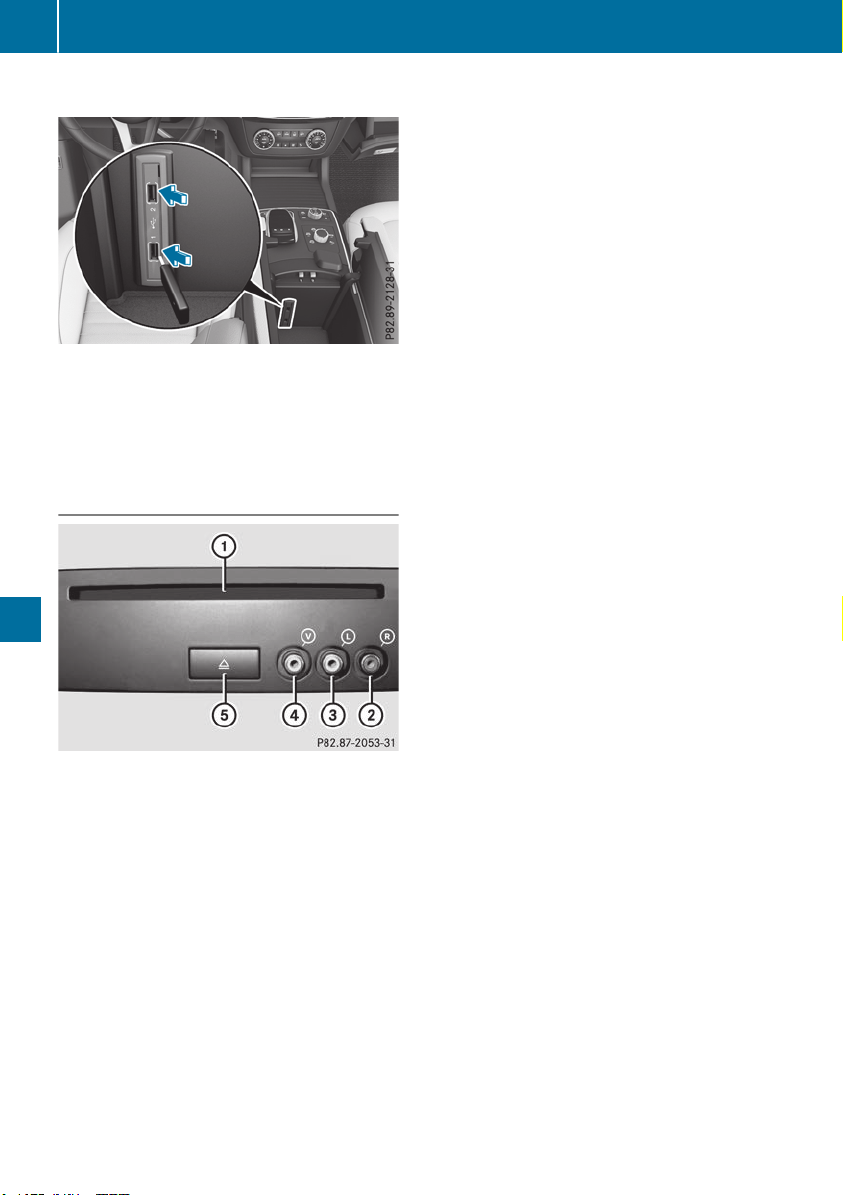
Connecting USB devices
X
Connect the USB device to the USB port.
There are two USB ports in the stowage space
under the armrest.
X
Select the media source (Y page 293).
CD/DVD drive and AUX jacks (Rear Seat
Entertainment System)
:
Disc slot
;
AUX, right-hand (R) jack for audio signal
(red)
=
AUX, left-hand (L) jack for audio signal
(white)
?
AUX, video (V) jack (yellow)
A
Disc eject button
The AUX jacks shown are for the AUX drive.
Identical jacks can be found on the right-hand
side of the rear-passenger compartment
screens (AUX display).
294
Operating system
Multimedia system

Stowage areas
Loading guidelines
G
WARNING
If objects, luggage or loads are not secured or
not secured sufficiently, they could slip, tip
over or be flung around and thereby hit vehicle
occupants. There is a risk of injury, particu-
larly in the event of sudden braking or a sud-
den change in direction.
Always store objects so that they cannot be
flung around. Secure objects, luggage or
loads against slipping or tipping before the
journey.
G
WARNING
Combustion engines emit poisonous exhaust
gases such as carbon monoxide. If the tailgate
is open when the engine is running, particu-
larly if the vehicle is moving, exhaust fumes
could enter the passenger compartment.
There is a risk of poisoning.
Turn off the engine before opening the tail-
gate. Never drive with the tailgate open.
G
WARNING
The exhaust tail pipe and tail pipe trim can
become very hot. If you come into contact
with these parts of the vehicle, you could burn
yourself. There is a risk of injury.
Always be particularly careful around the
exhaust tail pipe and the tail pipe trim. Allow
these components to cool down before touch-
ing them.
The gross vehicle weight (GVW) is the vehicle
weight including fuel, vehicle tool kit, spare
wheel, installed accessories, vehicle occupants
and luggage/cargo.
Do not exceed the load limit or permitted gross
vehicle weight rating (GVWR) for your vehicle.
The gross load limit and the GVWR are specified
on the vehicle identification plate on the B-pillar
of the driver's door (Y page 361).
The load must also be distributed so that the
weight on each axle never exceeds the gross
axle weight rating (GAWR) for the front and rear
axles. The specifications for GVWR and GAWR
are on the vehicle identification plate on the B-
pillar of the driver's door (Y page 361).
Observe the notes on loading the vehicle
(Y page 361).
The handling characteristics of a laden vehicle
are dependent on the distribution of the load
within the vehicle. For this reason, you should
observe the following notes when transporting a
load:
R
Never exceed the maximum permissible
gross vehicle mass or the gross axle weight
rating for the vehicle (including occupants).
R
The cargo compartment is the preferred place
to carry objects.
R
Position heavy loads as far forward as possi-
ble and as low down in the cargo compart-
ment as possible.
R
The load must not protrude above the upper
edge of the seat backrests.
R
Always place the load against the rear or front
seat backrests. Make sure that the seat
backrests are securely locked into place.
R
Always place the load behind unoccupied
seats if possible.
R
Use the cargo tie-down rings and the parcel
nets to transport loads and luggage.
R
Use cargo tie-down rings and fastening mate-
rials appropriate for the weight and size of the
load.
R
Secure the load with sufficiently strong and
wear-resistant tie-downs. Pad sharp edges for
protection.
Stowage spaces
Important safety notes
G
WARNING
If you transport objects in the vehicle interior
and these are not adequately secured, they
could slip or be flung around and thereby
strike vehicle occupants. In addition, cup
holders, open stowage spaces and mobile
phone brackets may not always be able to
hold the objects placed in them in the event of
an accident. There is a risk of injury, particu-
larly in the event of sharp braking or sudden
changes of direction.
Stowage areas
295
Stowage and features
Z
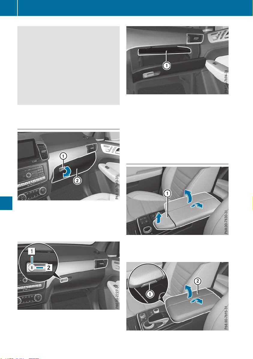
R
Always stow objects in such a way that they
cannot be tossed about in these or similar
situations.
R
Always make sure that objects do not pro-
trude out of the stowage spaces, luggage
nets or stowage nets.
R
Ensure that closable stowage spaces are
shut before beginning your journey.
R
Always stow and secure heavy, hard, poin-
ted, sharp-edged, fragile or large objects in
the cargo compartment.
Observe the loading guidelines (Y page 295).
Glove box
X
To open: pull handle : and open glove box
flap ;.
X
To close: fold glove box flap ; up until it
engages.
i
The glove box can be cooled (Y page 132).
1
Glove box unlocked
2
Glove box locked
The glove box can be locked and unlocked using
the mechanical key.
Partition : for stowing flat objects is located in
the upper section of the glove box. It can be
removed to increase the stowage space in the
glove box.
X
To remove: pull out partition :.
X
To install: insert partition : and push it back
until it engages.
Stowage compartment under the arm-
rest
Vehicles without touchpad
X
To open: pull handle : up.
The armrest folds out.
296
Stowage areas
Stowage and features
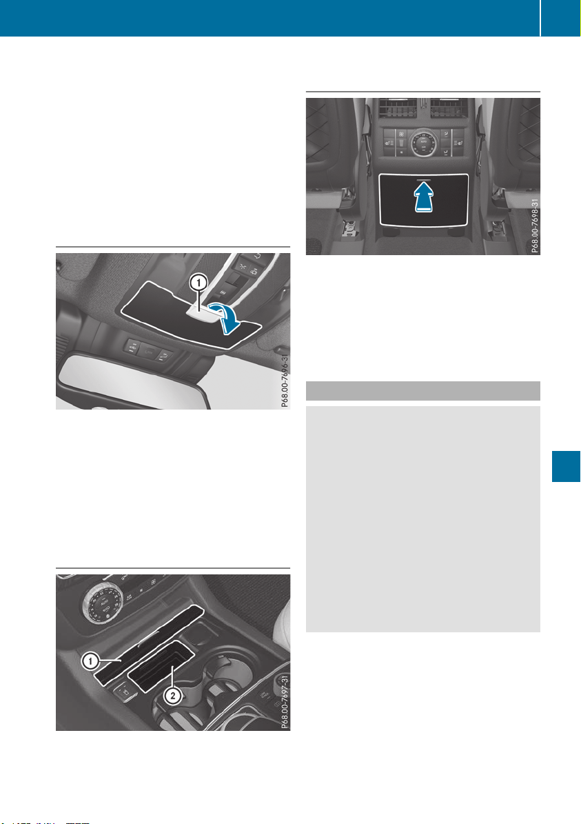
Vehicles with touchpad and COMAND
X
To open: press button : at the front.
Armrest ; folds out.
Depending on the vehicle equipment, there is a
multimedia connection unit with two USB ports,
e.g. for iPod
®
, iPhone
®
or MP3 player in the
stowage compartment .
i
There is a removable stowage tray in the
storage compartment, in which objects such
as an iPod
®
can be stored.
Eyeglasses compartment
X
To open: press marking :.
The eyeglasses compartment opens down.
X
To close: press marking : again and the
eyeglasses compartment moves up and
engages.
Make sure that the eyeglasses compartment is
always closed while the vehicle is in motion.
Stowage compartment in the front cen-
ter console
X
To open: slide cover : forwards.
Stowage compartment ; appears.
X
To close: pull cover : back as far as it will go.
Stowage compartment in the rear cen-
ter console
X
To open: briefly press the stowage compart-
ment marking.
The stowage compartment opens.
i
Depending on the vehicle's equipment,
there may be open stowage spaces above and
below the stowage compartment.
Stowage net
G
WARNING
Vehicles with the Occupant Classification
System (OCS):
If the gross weight of the objects in the stow-
age net on the back of the front-passenger
seat is greater than 4.4 lb (2 kg), OCS cannot
correctly assess the occupant's weight cate-
gory. The front-passenger front air bag could
deploy without cause, or may fail to deploy in
the event of an accident. This poses an
increased risk of injury or even fatal injury.
Always observe the permissible gross weight
of 4.4 lb (2 kg). Stow and secure heavy
objects in the cargo compartment.
Stowage nets are located in the front-passenger
footwell and on the back of the driver's and the
front-passenger seat.
Observe the loading guidelines (Y page 295)
and the safety notes regarding stowage spaces
(Y page 295).
Stowage areas
297
Stowage and features
Z
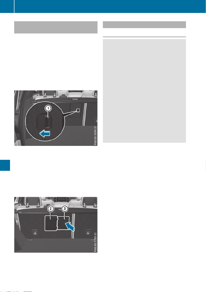
Through-loading facility in the rear
passenger compartment
There is a through-loading facility above the
armrest in the rear for transporting longer
objects. You can continue to use both of the
outer rear seats.
If objects or loads are not secured when being
transported in the through-loading facility, they
could slip or be thrown around and thereby hit
vehicle occupants.
Observe the loading guidelines (Y page 295)
and the safety notes regarding stowage spaces
(Y page 295).
The through-loading facility is opened from the
cargo compartment.
X
Fold down the rear seat armrest.
X
Pull the center head restraint on the rear
bench seat into the uppermost position
(Y page 99).
X
Slide release catch : to the left and swing
flap ; to the left until it is lying on the rear
side of the rear bench seat.
X
Push cover = forward until it is lying on the
rear seat armrest.
Cargo compartment enlargement
Important safety notes
G
WARNING
If the rear bench seat/rear seat and seat
backrest are not engaged they could fold for-
wards, e.g. when braking suddenly or in the
event of an accident.
R
The vehicle occupant would thereby be
pushed into the seat belt by the rear bench
seat/rear seat or by the seat backrest. The
seat belt can no longer offer the intended
level of protection and could even cause
injuries.
R
Objects or loads in the trunk/cargo com-
partment cannot be restrained by the seat
backrest.
There is an increased risk of injury.
Before every trip, make sure that the seat
backrests and the rear bench seat/rear seat
are engaged.
Make sure that the seat backrest and the seat
cushion are correctly engaged in position. To do
so, pull firmly on the seat backrest.
!
Fold the seat cushion upwards before fold-
ing the rear bench seat forward. Otherwise,
the backrests may be damaged.
When the backrest is folded forwards, the
front seats should not be moved to their rear-
most position. Otherwise, the front seats and
the rear bench seat could be damaged.
!
The backrest is heavy. Therefore, take care
when folding it down. Make sure that the head
restraints are pushed all the way in so that the
backrests and seat cushions are not dam-
aged.
Observe the loading guidelines (Y page 295).
The left-hand and right-hand rear seat backrests
can be folded forward separately to increase the
cargo compartment capacity.
298
Stowage areas
Stowage and features
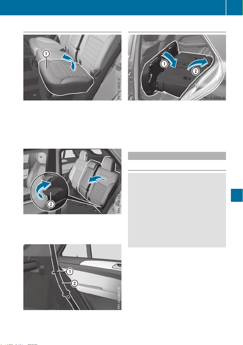
Folding the rear bench seat forward
If the driver's or front-passenger seat is set for a
larger person, it may not be possible to fold the
rear bench seat forward. In this case, move the
front seats as far forward as possible.
X
Move the head restraints to the lowest posi-
tion (Y page 100).
X
Fold seat cushion : up.
X
Pull release handle ; up in the direction of
the arrow until the backrest is fully released.
X
Fold the backrest forward until it reaches the
cargo compartment position.
X
Guide seat belts ; under respective clips :.
Folding the rear bench seat back
X
Fold seat backrest ; back until it engages.
Make sure not to trap the seat belt while doing
so.
X
Swing seat cushion : back.
X
Pull up and adjust the head restraints if nec-
essary (Y page 100).
Securing loads
Cargo tie-down rings
G
WARNING
The Top Tether anchorages cannot secure a
load. If you secure a load with the Top Tether
anchorages, the Top Tether anchorages could
be pulled out during braking, abrupt changes
in direction or in the event of an accident. The
load could slip, tip over or be flung around and
thereby hit vehicle occupants. There is a risk
of injury.
Only use the cargo tie down rings when secur-
ing a load.
Observe the following notes on securing loads:
R
Secure the load using the cargo tie-down
rings.
R
Distribute the load on the cargo tie-down
rings evenly.
R
Do not use elastic straps or nets to secure a
load, as these are only intended as an anti-slip
protection for light loads.
R
Do not route tie-downs across sharp edges or
corners.
R
Pad sharp edges for protection.
Stowage areas
299
Stowage and features
Z
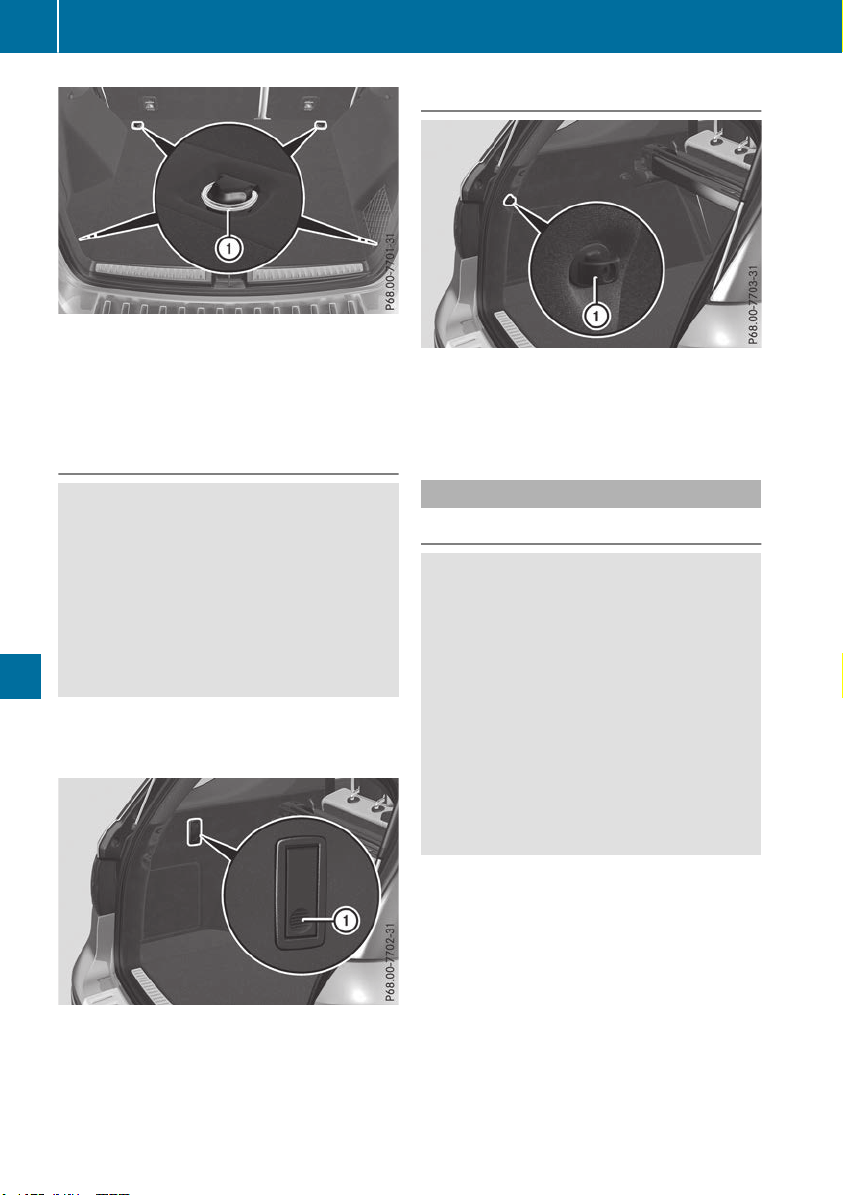
There are four cargo tie-down rings : in the
cargo compartment.
The parcel net must be pushed down before
using the cargo tie-down rings on the front right-
hand side of the cargo compartment.
Bag hook
G
WARNING
The bag hooks cannot restrain heavy objects
or items of luggage. Objects or items of lug-
gage could be flung around and thereby hit
vehicle occupants when braking or abruptly
changing directions. There is a risk of injury.
Only hang light objects on the bag hooks.
Never hang hard, sharp-edged or fragile
objects on the bag hooks.
!
The bag hook can bear a maximum load of
6.6lbs (3kg) and should not be used to secure
a load.
There is a bag hook in the cargo compartment
on the left-hand side.
X
Press bag hook marking :.
X
Turn bag hook : until it engages.
Securing hooks
There is a securing hook : on each side of the
cargo compartment.
Only secure lightweight luggage items on the
securing hooks (maximum 9 lbs (4 kg)).
Cargo compartment cover
Important safety notes
G
WARNING
On its own, the cargo compartment cover
cannot secure or restrain heavy objects,
items of luggage and heavy loads. You could
be hit by an unsecured load during sudden
changes in direction, braking or in the event of
an accident. There is an increased risk of
injury or even fatal injury.
Always store objects so that they cannot be
flung around. Secure objects, luggage or
loads against slipping or tipping over, e.g. by
using tie downs, even if you are using the
cargo compartment cover.
!
When loading the vehicle, make sure that
you do not stack the load in the cargo com-
partment higher than the lower edge of the
side windows. Do not place heavy objects on
top of the cargo compartment cover.
A cargo compartment cover or a combined
cargo cover and net (cargo compartment cover
with cargo net) is installed, depending on equip-
ment, behind the rear bench seat backrest.
300
Stowage areas
Stowage and features
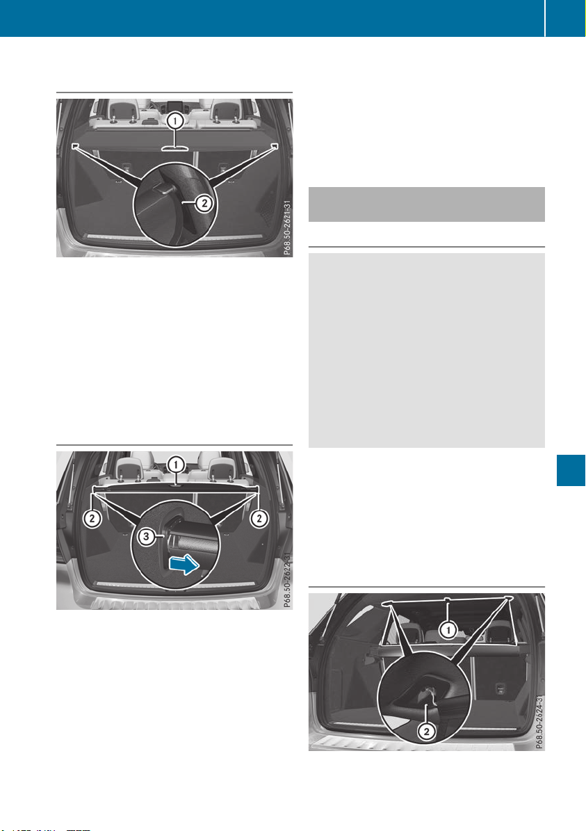
Extending/retracting the cargo com-
partment cover
X
To extend: pull the cargo compartment cover
back by grab handle : and clip it into retain-
ers ; on the left and right.
X
To retract: unhook the cargo compartment
cover from left-hand and right-hand retain-
ers ;.
X
Guide cargo compartment cover forwards by
grab handle : until it is completely rolled up.
Removing/installing the cargo com-
partment cover (without integrated
cargo net)
X
To remove: make sure that cargo compart-
ment cover : is rolled up.
X
Push end cap = of cargo compartment
cover : in the direction of the arrow on the
right or left-hand side.
X
Push cargo compartment cover : into oppo-
site anchorage ;.
X
Remove cargo compartment cover :.
X
To install: place cargo compartment
cover : into anchorage ; on the right or
left-hand side.
X
Push in opposite end cap = of cargo com-
partment cover : in the direction of the
arrow and insert cargo compartment
cover : into opposite anchorage ;.
Cargo net in combined cargo cover
and net
Important safety notes
G
WARNING
On its own, the cargo net cannot secure or
restrain heavy objects, items of luggage and
heavy loads. You could be hit by an unsecured
load during sudden changes in direction,
braking or in the event of an accident. There is
an increased risk of injury or even fatal injury.
Always store objects so that they cannot be
flung around. Secure objects, luggage or
loads against slipping or tipping over, e.g. by
using tie downs, even if you are using the
cargo net.
It is important to use a cargo net if you load the
vehicle with small objects above the seat backr-
ests. For safety reasons, always use a cargo net
when transporting loads.
Damaged cargo nets can no longer fulfill their
protective function and must be replaced. Visit a
qualified specialist workshop.
Attaching the cargo net
X
Pull the cargo net up by tab : and hook it into
eyelets ; using both hands.
Stowage areas
301
Stowage and features
Z
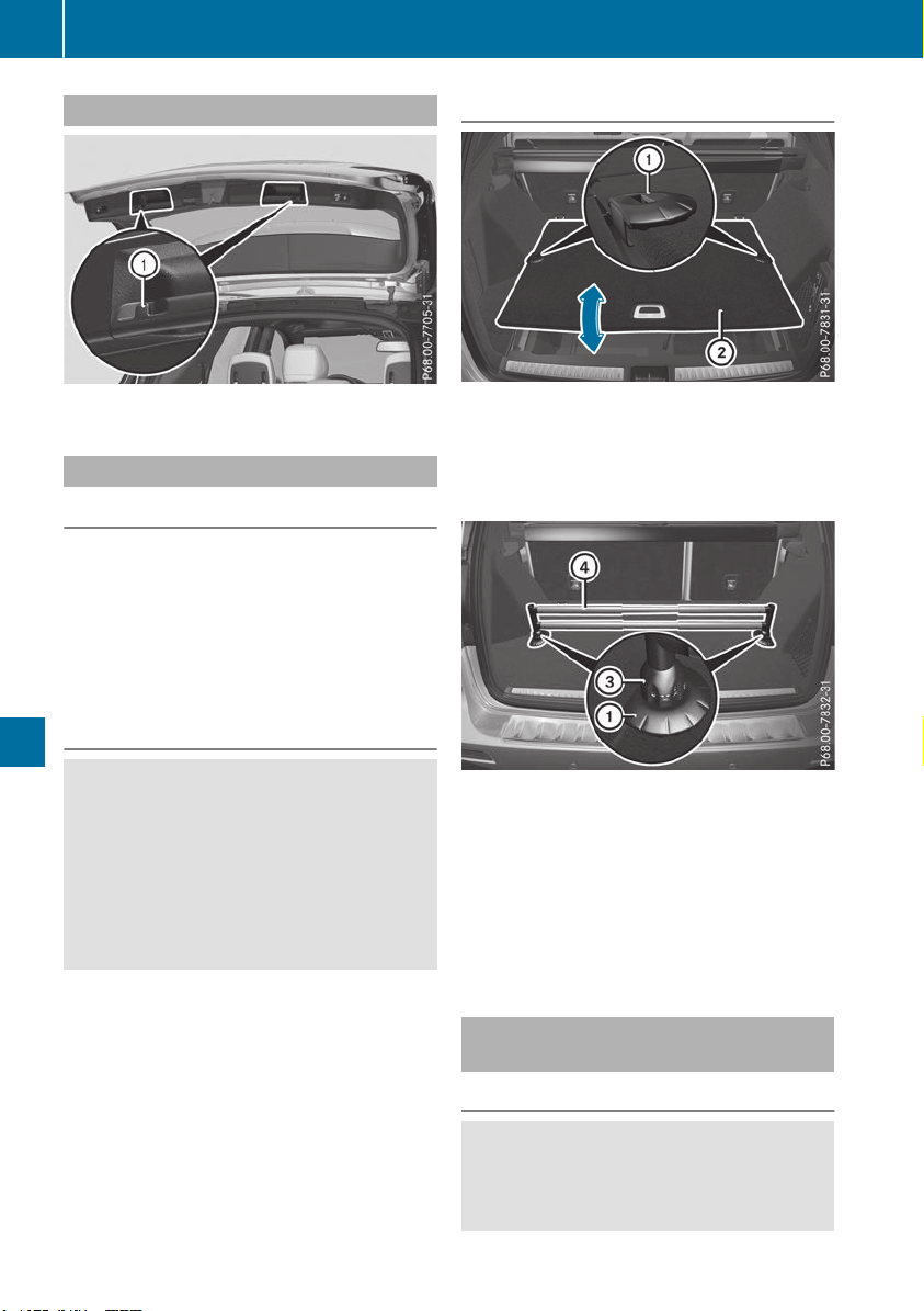
Coat hooks on the tailgate
:
Coat hook
EASY-PACK load-securing kit
General notes
The EASY-PACK load-securing kit allows you to
use your cargo compartment for a variety of
purposes. The following accessory parts are
located under the cargo compartment floor:
R
a telescopic rod
R
two mounting elements
R
two brackets
Important safety notes
G
WARNING
If you drive when the cargo compartment floor
is open, objects could be flung around, thus
striking vehicle occupants. There is a risk of
injury, particularly in the event of sudden
braking or a sudden change in direction.
Always close the cargo compartment floor
before a journey.
Installation
X
Open cargo compartment floor ;
(Y page 302).
X
Attach brackets : in the desired position on
the side of cargo compartment floor ;.
X
Close cargo compartment floor ;.
X
Turn mounting elements = to =.
X
Insert mounting elements = into brack-
ets :.
X
Pull telescopic rod ? apart.
X
Insert telescopic rod ? into mounting ele-
ments =.
X
Turn both mounting elements = to & until
you feel them engage.
Stowage well under the cargo com-
partment floor
Important safety notes
G
WARNING
If you drive when the cargo compartment floor
is open, objects could be flung around, thus
striking vehicle occupants. There is a risk of
302
Stowage areas
Stowage and features
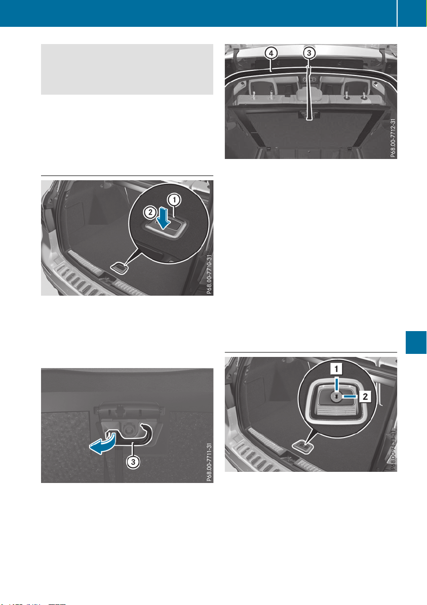
injury, particularly in the event of sudden
braking or a sudden change in direction.
Always close the cargo compartment floor
before a journey.
The accessory parts of the EASY–PACK load-
securing kit, as well as TIREFIT and the tire-
changing tools are located in the removable
insert in the stowage well.
Opening/closing the cargo compart-
ment floor
X
To open: holding the ribbing, press handle :
down ;.
Handle : folds up.
X
Swing the cargo compartment floor up using
handle : until it rests against the cargo com-
partment cover.
X
Fold out hook = on the underside of the
cargo compartment floor in the direction of
the arrow.
X
Attach hook = to the cargo compartment's
upper seal ?.
X
To close: detach hook = from the cargo
compartment's upper seal ?.
X
Fasten hook = to the retainer on the under-
side of the cargo compartment floor.
X
Fold the cargo compartment floor down.
X
Press the cargo compartment floor down ;
until it engages.
i
To remove the cargo compartment floor,
undo the press studs below the cargo com-
partment floor. When you re-install the cargo
compartment floor, fasten it with the press
studs.
Locking/unlocking the cargo compart-
ment floor
1
Cargo compartment floor unlocked
2
Cargo compartment floor locked
The cargo compartment floor can be locked and
unlocked using the mechanical key.
Stowage areas
303
Stowage and features
Z
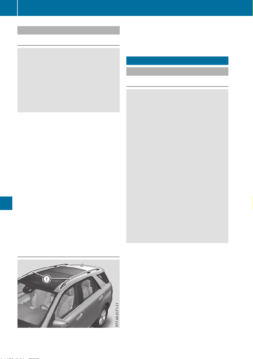
Roof carrier
Important safety notes
G
WARNING
When you load the roof, the center of gravity
of the vehicle rises and the driving character-
istics change. If you exceed the maximum roof
load, the driving characteristics, as well as
steering and braking, will be greatly impaired.
There is a risk of an accident.
Never exceed the maximum roof load and
adjust your driving style.
!
Mercedes-Benz recommends that you only
use roof carriers that have been tested and
approved for Mercedes-Benz vehicles. This
helps to prevent damage to the vehicle.
Position the load on the roof carrier in such a
way that the vehicle will not sustain damage
even when it is in motion.
Depending on the vehicle equipment, ensure
that when the roof carrier is installed you can:
R
raise the sliding sunroof fully
R
open the panorama roof with power tilt/
sliding panel fully
R
open the tailgate fully
You will find information on the maximum roof
load in the "Technical data" section
(Y page 390).
An incorrectly secured roof carrier or roof load
may become detached from the vehicle. You
must therefore ensure that you observe the roof
carrier manufacturer's installation instructions.
Attaching the roof carrier
X
Secure the roof carrier to roof rails :. In
doing so, observe the manufacturer's instal-
lation instructions.
Features
Cup holder
Important safety notes
G
WARNING
If you transport objects in the vehicle interior
and these are not adequately secured, they
could slip or be flung around and thereby
strike vehicle occupants. In addition, cup
holders, open stowage spaces and mobile
phone brackets may not always be able to
hold the objects placed in them in the event of
an accident. There is a risk of injury, particu-
larly in the event of sharp braking or sudden
changes of direction.
R
Always stow objects in such a way that they
cannot be tossed about in these or similar
situations.
R
Always make sure that objects do not pro-
trude out of the stowage spaces, luggage
nets or stowage nets.
R
Ensure that closable stowage spaces are
shut before beginning your journey.
R
Always stow and secure heavy, hard, poin-
ted, sharp-edged, fragile or large objects in
the cargo compartment.
Observe the loading guidelines (Y page 295).
!
Only use the cup holders for containers of
the right size and which have lids. The drinks
could otherwise spill.
!
Do not expose drinks bottles in the cup
holder in the center console to continuous,
strong and direct sunlight. The passenger
compartment in the area of the center con-
sole can otherwise be damaged by the con-
centrated and reflected sunlight.
Do not keep the KEYLESS-GO key in the tem-
perature-controlled cup holder (Y page 305).
Otherwise, the KEYLESS-GO key will not be rec-
ognized.
304
Features
Stowage and features
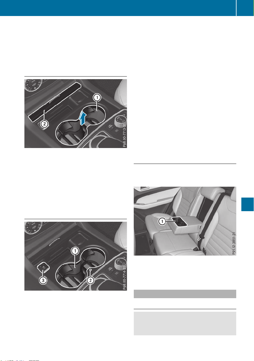
The stowage compartments in the doors provide
space for bottles with a capacity of up to
34 fl. oz. (1.0 l).
The bottles are not secured or prevented from
tipping over. Therefore, do not place any open
drink containers in the stowage compartments.
Cup holder in the front center console
:
Cup holder
;
Cover
X
To open: slide cover ; to its foremost posi-
tion.
X
To close: pull cover ; back as far as it will go.
You can remove the cup holder's rubber mat for
cleaning. Clean with clear, lukewarm water only.
Temperature-controlled cup holder in
the front-compartment center console
:
Cup holder
;
Residual heat indicator lamp
=
Switch
The temperature-controlled cup holder can be
used to keep cold drinks cool and warm drinks
warm.
X
Turn the SmartKey to position 2 in the igni-
tion lock.
X
To switch on the cooling function: press
and hold button = until the blue indicator
lamp on the button lights up.
X
To switch on the heating function: press
and hold button = until the red indicator
lamp on the button lights up.
X
To switch off the function: press and hold
button = until the indicator lamp on the but-
ton goes out.
When the heating function is used, the metal
insert of the cup holder is heated. Once a certain
temperature is reached, residual heat indicator
lamp ; lights up. This means that the metal
insert of the cup holder is hot. For this reason,
you must not reach into the cup holder metal
insert.
Do not use hard or sharp objects to clean the
cup holder. Use only a soft cloth to clean it.
Cup holder in the rear seat armrest
!
Do not sit on or support your body weight on
the rear seat armrest when it is folded down,
as you could otherwise damage it.
X
Fold down the rear seat armrest.
Cup holder : is located in the rear seat arm-
rest.
Sun visors
Overview
G
WARNING
If the mirror cover of the vanity mirror is folded
up when the vehicle is in motion, you could be
Features
305
Stowage and features
Z
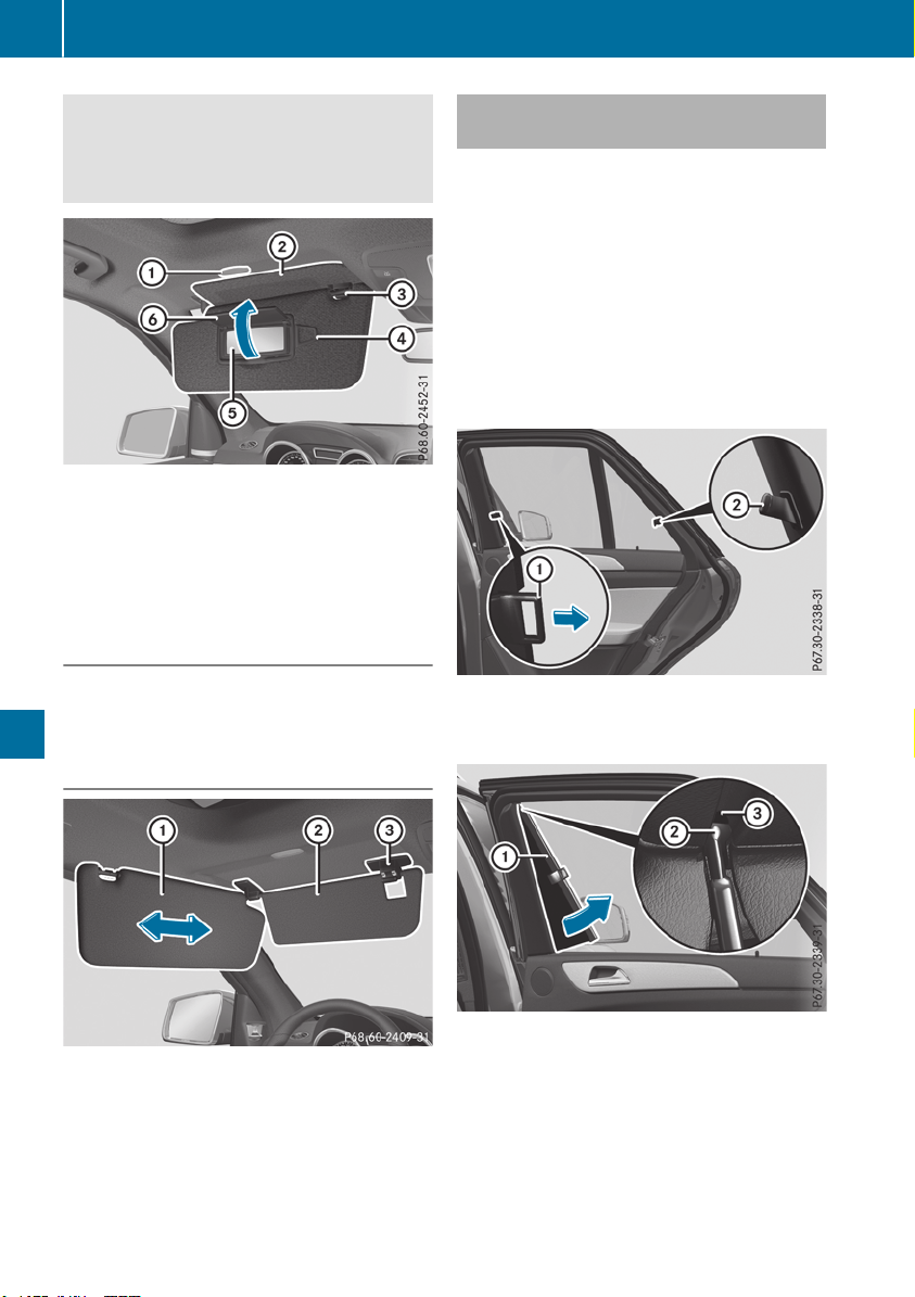
blinded by incident light. There is a risk of an
accident.
Always keep the mirror cover folded down
while driving.
:
Mirror light
;
Additional sun visor
=
Retainer
?
Retaining clip, e.g. for a car park ticket
A
Vanity mirror
B
Mirror cover
Vanity mirror in the sun visor
Mirror light : only functions if the sun visor is
clipped into retainer = and mirror cover B has
been folded up.
Glare from the side
X
Fold down sun visor :.
X
Pull sun visor : out of retainer =.
X
Swing sun visor : to the side.
Vehicles with additional sun visor:
X
Slide sun visor : horizontally as required.
X
Fold down additional sun visor ; to the wind-
shield.
Roller sunblinds on the rear side win-
dows
!
Always guide the roller sunblind by hand. Do
not let it snap back suddenly as this would
damage the automatic roller mechanism.
!
Do not drive the vehicle with the roller sun-
blind hooked in and the side windows opened
simultaneously. The roller sunblind can jump
out of the retainers and spring back suddenly
when driving at high speeds, e.g. when driving
on the freeway. This could damage the inertia
reel. Therefore, either close the side window
or retract the roller sunblind before driving at
high speeds.
X
To extend: pull the roller sunblind out by
tab : and hook it onto retainers ; at the
back of the window.
The roller sunblind can be hooked back into
place should it pop out from the top of the guide
rail.
X
Tilt pull-out profile : as illustrated.
X
Slip guide bush ; into open area of guide rail
=.
X
Straighten up pull-out profile : again.
306
Features
Stowage and features
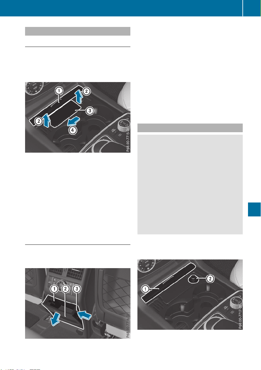
Ashtray
Front ashtray
!
The holder under the ashtray is not heat
resistant. Before placing lit cigarettes in the
ashtray, make sure that the ashtray is prop-
erly engaged. Otherwise, the holder could be
damaged.
X
To open: slide cover : to its foremost posi-
tion.
X
Fold cover = of the insert upwards.
X
To remove the insert: push insert = to the
left ?.
Insert = slides out slightly to the right.
X
Lift insert = up ; and out.
X
To re-install the insert: place insert = into
the holder and press it down on the right until
it engages.
X
To close: pull cover : back as far as it will go.
Rear-compartment ashtray
!
Close the ashtray when it is not in use and
before you fold the rear seats forward. You
can otherwise damage the ashtray.
Vehicles without a Rear Seat Entertainment Sys-
tem have an ashtray in the center console in the
rear compartment.
X
To open: briefly press cover ; at the top.
The ashtray opens.
X
To remove the insert: push into recess =
from the right.
Ashtray insert : slides out slightly to the
right.
X
Lift insert : up and out.
X
To re-install the insert: place insert : into
the holder and press down on the right until it
engages.
Cigarette lighter
G
WARNING
You can burn yourself if you touch the hot
heating element or the socket of the cigarette
lighter.
In addition, flammable materials can ignite if:
R
the hot cigarette lighter falls
R
a child holds the hot cigarette lighter to
objects, for example
There is a risk of fire and injury.
Always hold the cigarette lighter by the knob.
Always make sure that the cigarette lighter is
out of reach of children. Never leave children
unsupervised in the vehicle.
!
The cigarette lighter in the center console in
the front compartment is not intended for
operating the tire inflation compressor.
Your attention must always be focused on the
traffic conditions. Only use the cigarette lighter
when road and traffic conditions permit.
Features
307
Stowage and features
Z
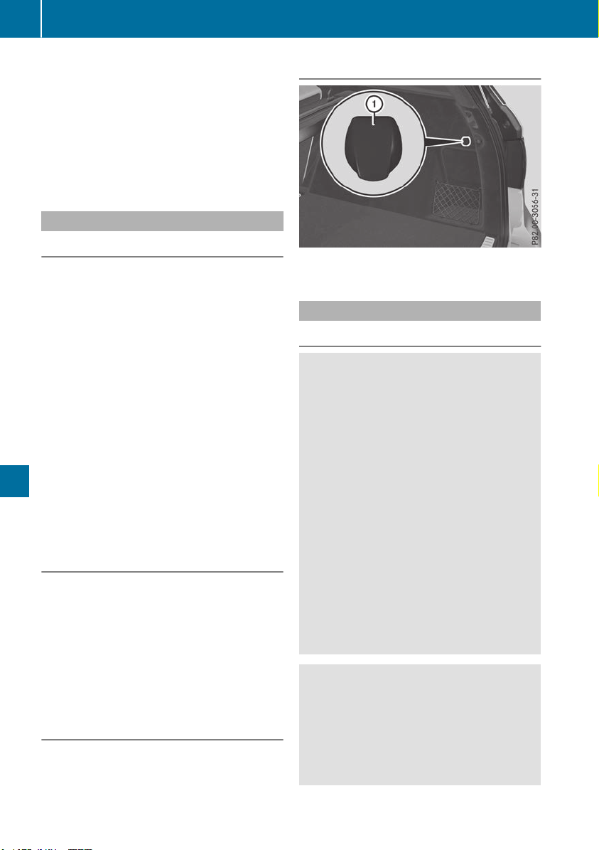
X
Turn the SmartKey to position 2 in the igni-
tion lock (Y page 135).
X
To open: slide cover : to its foremost posi-
tion.
X
Press in cigarette lighter ;.
Cigarette lighter ; will pop out automatically
when the heating element is red-hot.
X
To close: pull cover : back as far as it will go.
12 V sockets
General notes
X
Turn the SmartKey to position 1 in the igni-
tion lock (Y page 135).
With the exception of the socket in the front
center console, all sockets can be used for
accessories with a maximum current draw of
240 W (20 A). The socket in the front center
console can be used for accessories with a max-
imum current draw of 180 W(15 A). Accessories
include such items as chargers for mobile
phones.
If you use the sockets for long periods when the
engine is switched off, the battery may dis-
charge.
i
An emergency cut-out ensures that the on-
board voltage does not drop too low. If the on-
board voltage is too low, the power to the
sockets is automatically cut. This ensures
that there is sufficient power to start the
engine.
Socket in the front center console
!
The socket is not suitable for operating the
tire inflation compressor.
X
To open: slide the cover to its foremost posi-
tion.
X
Lift up the cover of the socket.
X
To close: pull the cover back as far as it will
go.
Socket in the rear passenger compart-
ment center console
Vehicles with the Rear Seat Entertainment Sys-
tem have two sockets in the center console in
the rear passenger compartment.
X
Lift up the cover of the socket.
Socket in the cargo compartment
X
Lift up the cover of socket :.
115 V socket
Important safety notes
G
DANGER
When a suitable device is connected, the
115 V power socket will be carrying a high
voltage. You could receive an electric shock if
the connector cable or the 115 V power
socket is pulled out of the trim or is damaged
or wet. There is a risk of fatal injury.
R
Use only connector cables that are dry and
free of damage.
R
When the ignition is off, make sure that the
115 V power socket is dry.
R
Have the 115 V power socket checked or
replaced immediately at a qualified speci-
alized workshop if it is damaged or has been
pulled out of the trim.
R
Never plug the connector cable into a 115 V
power socket that is damaged or has been
pulled out of the trim.
G
DANGER
If you reach into the power socket or plug
inappropriate devices into the power socket,
you could receive an electric shock. There is a
risk of fatal injury.
Only connect appropriate devices to the
power socket.
308
Features
Stowage and features
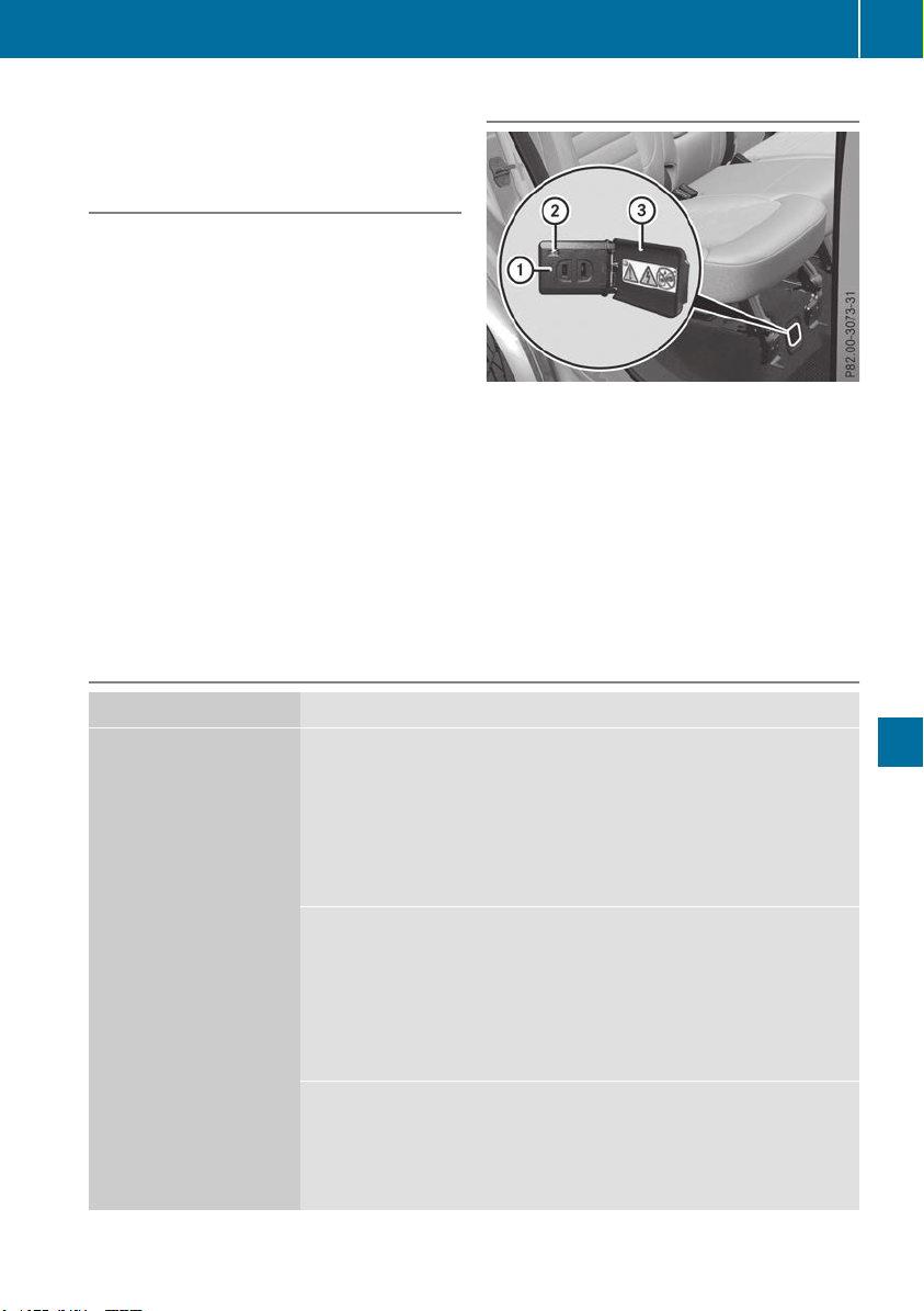
!
Note that work and repairs on the 115 V
power socket should only be carried out by
qualified specialist personnel.
General notes
The 115 Vpower socket provides an alternating
voltage of 115 V so that small electronic devices
can be connected. These devices, such as
games consoles, chargers and laptops, must not
consume more than a maximum of 150 watts
altogether.
Requirements for operation of these devices:
R
the electronic device that you connect has a
suitable connector and conforms to stand-
ards specific to the country you are in.
R
the plug of the electronic device is plugged
correctly into 115 V power socket.
R
the maximum wattage of the device to be
connected must not exceed 150 watts.
R
the on-board power supply is within a permis-
sible voltage range.
R
the 12 V sockets in the rear compartment and
the cargo compartment are operational.
Using the 115 V power socket
X
To switch on: switch the ignition on.
X
Open flap =.
X
Insert the plug of the electronic device into
115 V power socket :.
Indicator lamp ; lights up.
X
To switch off: disconnect the plug from
115 V power socket :.
Ensure that you do not pull on the cord.
Problems with the 115 V power socket
Problem
Possible causes/consequences and MM Solutions
The warning lamp on the
115 V power socket is
not lit.
The on-board voltage is too low because the battery is too weak.
X
Start the engine.
or
X
Charge the battery (Y page 342).
If the indicator lamp still does not light up:
X
Visit a qualified specialist workshop.
The temperature of the DC/AC converter is temporarily too high.
X
Remove the electronic device connector from the 115 V socket.
X
Let the DC/AC converter cool down.
If the indicator lamp still does not light up after cooling down the
converter:
X
Visit a qualified specialist workshop.
You have connected an electronic device that has a constant nominal
power of less than 150 watts, but has a very high switch-on current.
This device will not work. If you connect such a device, the 115 V
power socket will not supply it with power.
X
Connect a suitable electronic device.
Features
309
Stowage and features
Z

mbrace
General notes
The mbrace system is only available in the USA.
A license agreement must be in place in order to
activate the mbrace service. Make sure that
your system is activated and operational. To
register, press the ï Info call button. If any of
the steps mentioned are not carried out, the
system may not be activated.
If you have questions about the activation, con-
tact one of the following telephone hotlines:
Mercedes-Benz Customer Assistance Center at
1-800 FOR-MERCEDES (1-800-367-6372) or
1-866-990-9007
Shortly after successfully registering with the
mbrace service, a user ID and password will be
sent to you by mail. You can use this password
to log onto the mbrace area under "Owners
Online" at http://www.mbusa.com.
The system is available if:
R
it has been activated and is operational
R
the corresponding mobile phone network is
available for transmitting data to the Cus-
tomer Center
R
a service subscription is available
Determining the location of the vehicle on a map
is only possible if:
R
GPS reception is available
R
the vehicle position can be forwarded to the
Customer Assistance Center
The mbrace system
To adjust the volume during a call, proceed as
follows:
X
Press the W or X button on the multi-
function steering wheel.
or
X
Use the multimedia system volume control.
The system offers various services, e.g.:
R
Automatic and manual emergency call
R
Roadside Assistance call
R
Info call
You can find information and a description of all
available features under "Owners Online" at
http://www.mbusa.com.
System self-test
After you have switched on the ignition, the sys-
tem carries out a self-diagnosis.
A malfunction in the system has been detected
if one of the following occurs:
R
The indicator lamp in the SOS button does not
come on during the system self-test.
R
The indicator lamp in the F Roadside
Assistance button does not light up during
self-diagnosis of the system.
R
The indicator lamp in the ï Info call button
does not light up during the system self-diag-
nosis.
R
The indicator lamp in one or more of the fol-
lowing buttons continues to light up red after
the system self-diagnosis:
-
SOS button
-
F Roadside Assistance call button
-
ï Info call button
R
The InoperativeInoperative or the Service NotService Not
ActivatedActivated message appears in the multi-
function display after the system self-diagno-
sis.
If a malfunction is indicated as outlined above,
the system may not operate as expected. In the
event of an emergency, help will have to be
summoned by other means.
Have the system checked at the nearest author-
ized Mercedes-Benz Center or call the following
telephone assistance services:
Mercedes-Benz Customer Assistance Center at
1-800 FOR-MERCEDES (1-800-367-6372) or
1-866-990-9007.
Emergency call
Important safety notes
G
WARNING
It can be dangerous to remain in the vehicle,
even if you have pressed the SOS button in an
emergency if:
R
you see smoke inside or outside of the vehi-
cle, e.g. if there is a fire after an accident
R
the vehicle is on a dangerous section of
road
R
the vehicle is not visible or cannot easily be
seen by other road users, particularly when
dark or in poor visibility conditions
310
Features
Stowage and features
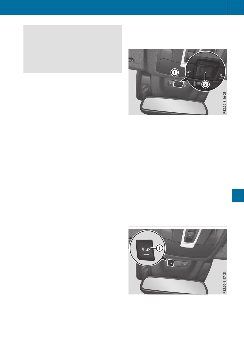
There is a risk of an accident and injury.
Leave the vehicle immediately in this or simi-
lar situations as soon as it is safe to do so.
Move to a safe location along with other vehi-
cle occupants. In such situations, secure the
vehicle in accordance with national regula-
tions, e. g. with a warning triangle.
General notes
Observe the notes on system activation
(Y page 310).
The emergency call is triggered automatically if
an air bag is deployed or an Emergency Ten-
sioning Device is triggered. You cannot end an
automatically triggered emergency call yourself.
An emergency call can also be initiated man-
ually.
As soon as the emergency call has been initi-
ated, the indicator lamp in the SOS button
flashes. The Connecting CallConnecting Call message
appears in the multifunction display.
The audio output is muted.
Once the connection has been made, the CallCall
ConnectedConnected message appears in the multifunc-
tion display.
All important information on the emergency is
transmitted, for example:
R
Current location of the vehicle (as determined
by the GPS system)
R
Vehicle identification number
R
Information on the severity of the accident
Shortly after the emergency call has been initi-
ated, a voice connection is automatically estab-
lished between the Customer Assistance Center
and the vehicle occupants.
R
If the vehicle occupants respond, the
Mercedes-Benz Customer Assistance Center
attempts to get more information on the
emergency.
R
If there is no response from the vehicle occu-
pants, an ambulance is immediately sent to
the vehicle.
R
If the relevant mobile phone network is not
available, no emergency call can be initiated.
The indicator lamp in the SOS button flashes
continuously.
No voice connection can be established to the
Mercedes-Benz Customer Assistance Center.
The CallCall FailedFailed message appears on the mul-
tifunction display and must be confirmed.
In this case, summon assistance by other
means.
Making an emergency call
X
To initiate an emergency call manually:
press cover : briefly to open.
X
Press and hold the SOS button for at least one
second ;.
The indicator lamp in SOS button ; flashes
until the emergency call is concluded.
X
Wait for a voice connection to the Mercedes-
Benz Customer Assistance Center.
X
After the emergency call, close cover :.
If the mobile phone network is unavailable,
mbrace will not be able to make the emergency
call. If you leave the vehicle immediately after
pressing SOS button ;, you do not know if
mbrace has successfully made the emergency
call. In this case, always summon assistance by
other means.
Breakdown assistance button
X
To call: press Roadside Assistance but-
ton :.
This initiates a call to the Mercedes-Benz Cus-
tomer Assistance Center.
Features
311
Stowage and features
Z
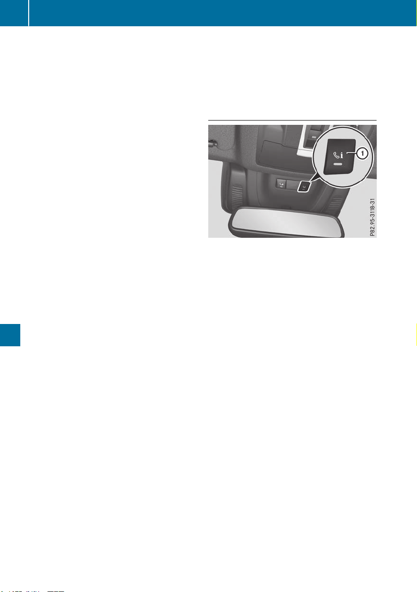
The indicator lamp in Roadside Assistance
button : flashes while the call is active. The
Connecting CallConnecting Call message appears in the
multifunction display. The audio output is
muted.
If a connection can be established, the CallCall
ConnectedConnected message appears in the multifunc-
tion display.
If a mobile phone network and GPS reception
are available, the system transfers data to the
Mercedes-Benz Customer Assistance Center,
for example:
R
Current location of the vehicle
R
Vehicle identification number
The multimedia system display indicates that a
call is active. During the call, you can change to
the navigation menu by pressing the NAVI but-
ton on the multimedia system, for example.
Voice output is not available in this case.
A voice connection is established between the
Mercedes-Benz Customer Assistance Center
and the vehicle occupants.
From the remote malfunction diagnosis, the
Mercedes-Benz Customer Assistance Center
can ascertain the nature of the problem
(Y page 315).
The Mercedes-Benz Customer Assistance Cen-
ter either sends a qualified Mercedes-Benz tech-
nician or makes arrangements for your vehicle
to be transported to the nearest Mercedes-Benz
Service Center.
You may be charged for services such as repair
work and/or towing.
You can find more information in the separate
mbrace manual.
The system has not been able to initiate a Road-
side Assistance call, if:
R
the F indicator lamp for the Roadside
Assistance call button is flashing continu-
ously.
R
no voice connection to the Mercedes-Benz
Customer Assistance Center was estab-
lished.
This can occur if the relevant mobile phone net-
work is not available, for example.
The Call FailedCall Failed message appears in the mul-
tifunction display.
X
To end a call: press the ~ button on the
multifunction steering wheel.
or
X
Press the corresponding multimedia system
button for ending a phone call.
Info call button
X
To call: press Info call button :.
This initiates a call to the Mercedes-Benz Cus-
tomer Assistance Center.
The indicator lamp in Info call button :
flashes while the connection is being made.
The Connecting CallConnecting Call message appears in
the multifunction display. The audio output is
muted.
If a connection can be established, the CallCall
ConnectedConnected message appears in the multifunc-
tion display.
If a mobile phone network and GPS reception
are available, the system transfers data to the
Mercedes-Benz Customer Assistance Center,
for example:
R
Current location of the vehicle
R
Vehicle identification number
The multimedia system display indicates that a
call is active. During the call, you can change to
the navigation menu by pressing the NAVI but-
ton on COMAND, for example.
Voice output is not available in this case.
A voice connection is established between the
Mercedes-Benz Customer Assistance Center
and the vehicle occupants.
You receive information about operating your
vehicle, about the nearest Mercedes-Benz Ser-
vice Center and about other products and serv-
ices from Mercedes-Benz.
312
Features
Stowage and features

You can find further information on the mbrace
system under "Owners Online" at
http://www.mbusa.com.
The system was unable to initiate an Info call if:
R
the indicator lamp in the ï Info call button
is flashing continuously.
R
no voice connection to the Mercedes-Benz
Customer Assistance Center has been estab-
lished.
This can occur if the relevant mobile phone net-
work is not available, for example.
The Call FailedCall Failed message appears in the mul-
tifunction display.
X
To end a call: press the ~ button on the
multifunction steering wheel.
or
X
Press the corresponding multimedia system
button for ending a phone call.
Call priority
When service calls are active, e.g. Roadside
Assistance or Info calls, an emergency call can
still be initiated. In this case, an emergency call
will take priority and override all other active
calls.
The indicator lamp of the respective button
flashes until the call is ended.
An emergency call can only be terminated by the
Mercedes-Benz Customer Assistance Center.
All other calls can be ended by pressing:
R
the ~ button on the multifunction steering
wheel
R
the corresponding button in the multimedia
system to end the voice call
When a call is initiated, the audio system is
muted.
The mobile phone is no longer connected to the
multimedia system.
However, if you want to use your mobile phone,
do so only when the vehicle is stationary and in
a safe location.
Downloading destinations in COMAND
Downloading destinations
Downloading destinations gives you access to a
database with over 15 million points of interest
(POIs). These can be downloaded on the navi-
gation system in your vehicle. If you know the
destination, the address can be downloaded.
Alternatively, you can obtain the location of
Points of Interest (POIs)/important destinations
in the vicinity.
Furthermore, you can download routes with up
to four way points.
You are prompted to confirm route guidance to
the address entered.
X
SelectYesYes by turning 3 or sliding 1
the controller and confirm with 7.
The system calculates the route and subse-
quently starts the route guidance with the
address entered.
If you select NoNo the address can be stored in
the address book.
The destination download function is available
if:
R
the vehicle is equipped with a navigation sys-
tem.
R
the relevant mobile phone network is availa-
ble and data transfer is possible.
Route Assistance
This service is part of the mbrace PLUS Package
and cannot be purchased separately.
You can use the Route Assistance function even
if the vehicle is not equipped with a navigation
system.
Within the framework of this service, you receive
a professional and reliable form of navigation
support without having to leave your vehicle.
The customer service representative finds a
suitable route depending on your vehicle's cur-
rent position and the desired destination. You
will then be guided live through the current route
section.
Search and Send
General notes
To use "Search & Send", your vehicle must be
equipped with mbrace and a navigation system.
Additionally, an mbrace service subscription
must be completed.
"Search & Send" is a service for entering desti-
nations in the navigation system. A destination
address which is found on Google Maps
®
can be
transferred via mbrace directly to your vehicle's
navigation system.
Features
313
Stowage and features
Z

Specifying and sending the destination
address
X
Go to the website http://maps.google.com
and enter a destination address into the entry
field.
X
To send the destination address to the e-
mail address of your mbrace account:
click on the corresponding button on the web-
site.
Example:
If you select "Send to vehicle" and then
"Mercedes-Benz", the destination address
will be sent to your vehicle.
X
When the "Send" dialog window appears:
Enter the e-mail address you specified when
setting up your mbrace account into the cor-
responding field.
X
Click "Send".
Information on specific commands such as
"Address entry" or "Send" can be found on the
website.
Calling up a transmitted destination
address
X
Turn the SmartKey to position 2 in the igni-
tion lock (Y page 135).
The transmitted destination address is loaded
into the vehicle's navigation system.
A display message appears, asking whether
navigation should be started.
X
SelectYesYes by turning 3 or sliding 1
the controller and confirm with 7.
The system calculates the route and subse-
quently starts the route guidance with the
address entered.
If you select NoNo the address can be stored in
the address book.
If you have sent more than one destination
address, each individual destination must be
confirmed separately.
Destination addresses are loaded in the same
order as the order in which they were sent.
If you have multiple Mercedes-Benz vehicles
with mbrace and active mbrace accounts:
If multiple vehicles are registered under the
same e-mail address, the destination will be
sent to all the vehicles.
Vehicle remote opening
You can use the vehicle remote unlocking if you
have unintentionally locked your vehicle and a
replacement SmartKey is not available.
The vehicle can then be unlocked by the
Mercedes-Benz Customer Assistance Center.
The vehicle can be immediately unlocked
remotely within four days of the ignition being
turned off. After this time, the remote unlocking
may be delayed by 15 to 60 minutes. After
30 days, the vehicle can no longer be unlocked
remotely.
The vehicle remote unlocking feature is availa-
ble if the relevant mobile phone network is avail-
able and a data connection is possible.
X
Contact the following service hotlines:
Mercedes-Benz Customer Assistance Center
at 1-800 FOR-MERCEDES (1-800-367-6372)
or 1-866-990-9007
You will be asked for your password.
X
Return to your vehicle at the time agreed upon
with the Mercedes-Benz Customer Assis-
tance Center.
Alternatively, the vehicle can be opened via:
R
the Internet, under the "Owners Online" sec-
tion
R
telephone applications (e.g. for iPhone
®
,
Android™)
To do this, you will need your identification num-
ber and password.
Vehicle remote closing
The vehicle remote closing feature can be used
when you have forgotten to lock the vehicle and
you are no longer nearby.
The vehicle can then be locked by the Mercedes-
Benz Customer Assistance Center.
The vehicle can be immediately remotely locked
within four days of the ignition being turned off.
After this time, remote closing may be delayed
by 15 to 60 minutes. After 30 days the vehicle
can no longer be locked remotely.
The vehicle remote closing feature is available if
the relevant mobile phone network is available
and a data connection is possible.
X
Contact the following service hotlines:
314
Features
Stowage and features

Mercedes-Benz Customer Assistance Center
at 1-800 FOR-MERCEDES (1-800-367-6372)
or 1-866-990-9007
You will be asked for your password.
The next time you are inside the vehicle and you
switch on the ignition, the Doors LockedDoors Locked
RemotelyRemotely message appears in the multifunction
display.
Alternatively, the vehicle can be locked via:
R
the Internet, under the "Owners Online" sec-
tion
R
telephone applications (e.g. for iPhone
®
,
Android™)
To do this, you will need your identification num-
ber and password.
Stolen vehicle recovery service
If your vehicle has been stolen:
X
Notify the police.
The police will issue a numbered incident
report.
X
Forward this number to the Mercedes-Benz
Customer Assistance Center along with your
PIN.
The Mercedes-Benz Customer Assistance
Center then tries to locate the system. The
Mercedes-Benz Customer Assistance Center
contacts you and the local law enforcement
agency if the vehicle is located.
However, only the law enforcement agency is
informed of the location of the vehicle.
If the anti-theft alarm system is activated for
longer than 30 seconds, mbrace automatically
notifies the Mercedes-Benz Customer Assis-
tance Center.
Vehicle Health Check
With the Vehicle Health Check, the Customer
Assistance Center can provide improved sup-
port for problems with your vehicle. During an
existing call, vehicle data is transferred to the
Customer Assistance Center.
The customer service representative can use
the received data to decide what kind of assis-
tance is required. You are then, for example,
guided to the nearest Mercedes-Benz Service
Center or a recovery vehicle is called.
If vehicle data need to be transferred during an
Info call or a Roadside Assistance call, this is
initiated by the Customer Assistance Center.
The Roadside Assistance ConnectedRoadside Assistance Connected mes-
sage appears in the display. If the Vehicle Health
Check can be started, the RequestRequest forfor Vehi‐Vehi‐
cle Diagnostics Received Start vehi‐cle Diagnostics Received Start vehi‐
cle diagnostics?cle diagnostics? message appears in the
display.
X
Press the YesYes button to confirm the message.
X
If the Vehicle Diagnostics PleaseVehicle Diagnostics Please
Start IgnitionStart Ignition message appears: turn the
SmartKey to key position 2 in the ignition
lock (Y page 135).
X
If the Please follow the instructionsPlease follow the instructions
receivedreceived byby phonephone andand movemove youryour vehi‐vehi‐
cle to a safe position.cle to a safe position. message
appears: please follow the instructions
received by phone and move your vehicle to a
safe position.
The message in the display disappears.
The vehicle operating state check begins.
During this procedure, you will see the Vehi‐Vehi‐
cle Diagnostics Activecle Diagnostics Active message.
If you select CancelCancel, the Vehicle Health
Check is canceled completely.
When the check is complete, the SendingSending
vehicle diagnostics data. (Voice con‐vehicle diagnostics data. (Voice con‐
nection may be interrupted duringnection may be interrupted during
datadata transfer)transfer) message appears. The vehicle
data can now be sent.
X
Press the OKOK button to confirm the message.
The voice connection with the Customer
Assistance Center is terminated.
The Vehicle Diagnostics: Transfer‐Vehicle Diagnostics: Transfer‐
ring Data...ring Data... message appears.
The vehicle data is sent to the Customer
Assistance Center.
Depending on what the customer service rep-
resentative agreed with you, the voice connec-
tion is re-established after the transfer is com-
plete. If necessary, you will be contacted at a
later time by another means, e.g. by e-mail or
phone.
Another function of the Vehicle Health Check is
the transfer of service data to the Customer
Assistance Center. If a service is due, the display
shows a message to this effect together with
information about any special offers at your
workshop.
This information can also be called up under
"Owners Online" at http://www.mbusa.com.
Information on the data stored in the vehicle
(Y page 32).
Features
315
Stowage and features
Z

Information on Roadside Assistance
(Y page 29).
Downloading routes
Downloading routes allows you to transfer and
save predefined routes in the navigation sys-
tem.
A route can be prepared and sent either by a
customer service representative or under "Own-
ers Online" at http://www.mbusa.com.
Each route can include up to four way points.
Once a route has been received by the naviga-
tion system, you will see the DoDo youyou wantwant toto
start route guidance? Destinationstart route guidance? Destination
Received destination has been savedReceived destination has been saved
in "Previous destinations".in "Previous destinations". message on
the multimedia system display.
The route is saved.
X
To start route guidance: select YesYes.
An overview of the route is shown in the dis-
play.
If you select NoNo, the saved route can be called
up later in the navigation menu.
X
Select StartStart.
Route guidance starts.
Downloaded and saved routes can be called up
again.
Speed alert
You can define the upper speed limit, which
must not be exceeded by the vehicle.
If the vehicle exceeds the set speed, a message
is sent to the Customer Assistance Center. The
Customer Assistance Center then forwards this
information to you.
You can select the way in which you receive this
information beforehand. Possible options
include text message, e-mail or an automated
call.
The data you receive contains the following
information:
R
the location where the speed limit was excee-
ded
R
the time at which the speed limit was excee-
ded
R
the selected speed limit which was exceeded
Geo fencing
Geo fencing allows you to select areas which the
vehicle should not enter or leave. You will be
informed if the vehicle crosses the boundaries
of the selected areas. You can select the way in
which you receive this information beforehand.
Possible options include text message, e-mail or
an automated call.
The area can be determined as either a circle or
a polygon with a maximum of ten corners. You
can specify up to ten areas simultaneously. Dif-
ferent settings are possible for each area.
These settings can be called up under "Owners
Online" at http://www.mbusa.com.
Alternatively, you can also trigger an Info call
and notify the customer service representative
that you wish to activate geo-fencing.
Currently inactive areas can be activated by text
message.
Triggering the vehicle alarm
With this function, you can trigger the vehicle's
panic alarm via text message. An alarm sounds
and the exterior lighting flashes. Depending on
the setting, the panic alarm lasts five or ten sec-
onds. Afterwards, the alarm switches off.
Garage door opener
General notes
The HomeLink
®
garage door opener integrated
in the rear-view mirror allows you to operate up
to three different door and gate systems.
Use the integrated garage door opener only on
garage doors that:
R
have safety stop and reverse features and
R
meet current U.S. federal safety standards
Once programmed, the integrated garage door
opener in the rear-view mirror will assume the
function of the garage door system's remote
control. Please also read the operating instruc-
tions for the garage door system.
When programming a garage door opener, park
the vehicle outside the garage. Do not run the
engine while programming.
Certain garage door drives are incompatible
with the integrated garage door opener. If you
have difficulty programming the integrated
316
Features
Stowage and features

garage door opener, contact a Mercedes-Benz
Service Center.
Alternatively, you can call the following tele-
phone assistance services:
R
USA: Mercedes-Benz Customer Assistance
Center at 1-800-FOR-MERCedes
R
Canada: Customer Service at
1-800-387-0100
R
HomeLink
®
hotline 1-800-355-3515 (free of
charge)
More information on HomeLink
®
and/or com-
patible products is also available on the Internet
at http://www.homelink.com.
Notes on the declaration of conformity
(Y page 30).
USA: FCC ID: CB2HMIHL4
Canada: IC: 279B-HMIHL4
Important safety notes
G
WARNING
When you operate or program the door with
the integrated garage door opener, persons in
the range of movement of the door may
become trapped or be struck by the door.
There is a risk of injury.
When using the integrated garage door
opener, always make sure that nobody is
within the range of movement of the door.
G
WARNING
Combustion engines emit poisonous exhaust
gases such as carbon monoxide. Inhaling
these exhaust gases leads to poisoning. There
is a risk of fatal injury. Therefore never leave
the engine running in enclosed spaces with-
out sufficient ventilation.
Programming
Programming the buttons
Pay attention to the "Important safety notes"
(Y page 317).
Garage door remote control A is not included
with the integrated garage door opener.
X
Turn the SmartKey to position 2 in the igni-
tion lock (Y page 135).
X
Select one of buttons ; to ? to use to con-
trol the garage door drive.
X
To start programming mode: press and
hold one of buttons ; to ? on the integrated
garage door opener.
The garage door opener is now in program-
ming mode. After a short time, indicator
lamp : lights up yellow.
Indicator lamp : lights up yellow as soon as
button ;, = or ? is stored for the first time.
If the selected button has already been pro-
gramed, indicator lamp : will only light up
yellow after ten seconds have elapsed.
X
Release button ;, = or ?. Indicator
lamp : flashes yellow.
X
To program the remote control: point
garage door remote control A towards but-
tons ; to ? on the rear-view mirror at a dis-
tance of 2 to 8 in (5 to 20 cm).
X
Press and hold button B on remote control
A until indicator lamp : lights up green.
When indicator lamp : lights up green: pro-
gramming is finished.
When indicator lamp : flashes green: pro-
gramming was successful. The next step is to
synchronize the rolling code (Y page 318).
X
Release button B on remote control A for
the garage door drive system.
If indicator lamp : lights up red: repeat the
programing procedure for the corresponding
button on the rear-view mirror. When doing
so, vary the distance between remote control
A and the rear-view mirror.
The required distance between remote con-
trol A and the integrated garage door opener
depends on the garage door drive system.
Features
317
Stowage and features
Z

Several attempts might be necessary. You
should test every position for at least
25 seconds before trying another position.
Synchronizing the rolling code
Pay attention to the "Important safety notes"
(Y page 317).
If the garage door system uses a rolling code,
you will also have to synchronize the garage
door system with the integrated garage door
opener in the rear-view mirror. To do this you will
need to use the programming button on the door
drive control panel. The programming button
may be located in different places depending on
the manufacturer. It is usually located on the
door drive unit on the garage ceiling.
Familiarize yourself with the garage door drive
operating instructions, e.g. under "Program-
ming additional remote controls", before carry-
ing out the following steps.
Your vehicle must be within reach of the garage
door or gate opener drive. Make sure that nei-
ther your vehicle nor any persons/objects are
present within the sweep of the door or gate.
X
Turn the SmartKey to position 2 in the igni-
tion lock (Y page 135).
X
Get out of the vehicle.
X
Press the programming button on the door
drive unit.
You now have 30 seconds to initiate the next
step.
X
Get into the vehicle.
X
Press previously programed button ;, =
or ? on the integrated garage door opener
repeatedly until the door closes.
The rolling code synchronization is then com-
plete.
Notes on programming the remote con-
trol
Canadian radio frequency laws require a "break"
(or interruption) of the transmission signals
after broadcasting for a few seconds. Therefore,
these signals may not last long enough for the
integrated garage door opener. The signal is not
recognized during programming. Comparable
with Canadian law, some U.S. garage door open-
ers also feature a "break".
Proceed as follows:
R
if you live in Canada.
R
if you have difficulties programming the
garage door opener (regardless of where you
live) when following the programming steps.
X
Press and hold one of buttons ; to ? on the
integrated garage door opener.
After a short time, indicator lamp : lights up
yellow.
X
Release the button.
Indicator lamp : flashes yellow.
X
Press button B of garage door remote con-
trol A for two seconds, then release it for two
seconds.
X
Press button B again for two seconds.
X
Repeat this sequence on button B of remote
control A until indicator lamp : lights up
green.
When indicator lamp : lights up green: pro-
gramming is finished.
When indicator lamp : flashes green: pro-
gramming was successful. The next step is to
synchronize the rolling code.
X
Release button B of remote control A of the
garage door drive.
When indicator lamp : lights up red: repeat
the programming process for the correspond-
ing button on the rear-view mirror. When
doing so, vary the distance between remote
control A and the rear-view mirror.
The required distance between remote con-
trol A and the integrated garage door opener
depends on the garage door drive system.
Several attempts might be necessary. You
should test every position for at least
25 seconds before trying another position.
Problems when programming
If you are experiencing problems programming
the integrated garage door opener on the rear-
view mirror, take note of the following instruc-
tions:
R
Check the transmitter frequency used by
garage door drive remote control A and
whether it is supported. The transmitter fre-
quency can usually be found on the back of
remote control A for the garage door drive.
The integrated garage door opener is com-
patible with devices that have units which
318
Features
Stowage and features
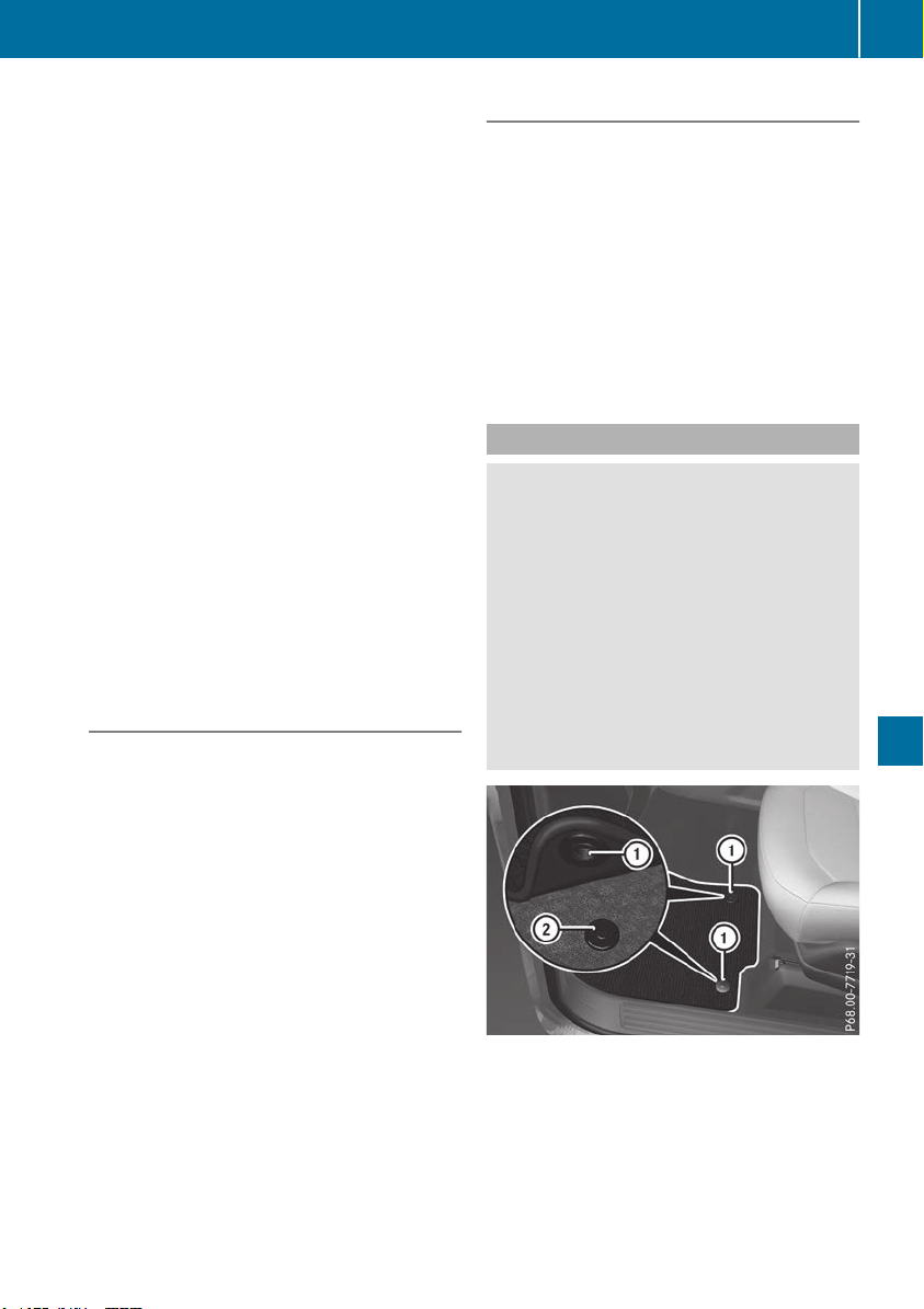
operate in the frequency range of 280 to
433 MHz.
R
Replace the batteries in garage door remote
control A. This increases the likelihood that
garage door remote control A will transmit a
strong and precise signal to the integrated
garage door opener.
R
When programming, hold remote control A
at varying distances and angles from but-
tons ; to ? which you are programming. Try
various angles at a distance between 2and
8 inches (5to 20 cm) or at the same angle but
at varying distances.
R
If a further remote control A is available for
the same garage door drive, repeat the same
programming steps with this remote control
A. Before performing these steps, make sure
that new batteries have been installed in
garage door drive remote control A.
R
Note that some remote controls only transmit
for a limited amount of time (the indicator
lamp on the remote control goes out). Press
button B on remote control A again before
transmission ends.
R
Align the antenna cable of the garage door
opener unit. This can improve signal recep-
tion/transmission.
Opening/closing the garage door
After it has been programmed, the integrated
garage door opener performs the function of the
garage door system remote control. Please also
read the operating instructions for the garage
door system.
X
Turn the SmartKey to position 2 in the igni-
tion lock (Y page 135).
X
Press button ;, = or ? which you pro-
grammed to operate the garage door.
Garage door system with a fixed code: indi-
cator lamp : lights up green.
Garage door system with a rolling code: indi-
cator lamp : flashes green.
The transmitter will transmit a signal as long
as the button is pressed. The transmission is
halted after a maximum of ten seconds and
indicator lamp : lights up yellow.
X
Press button ;, = or ? again if necessary.
Clearing the memory
Make sure that you clear the memory of the
integrated garage door opener before selling the
vehicle.
X
Turn the SmartKey to position 2 in the igni-
tion lock (Y page 135).
X
Press and hold buttons ; and ?.
Indicator lamp : initially lights up yellow and
then green.
X
Release buttons ; and ?.
The memory of the integrated garage door
opener in the rear-view mirror is cleared.
Floormats
G
WARNING
Objects in the driver's footwell can restrict the
pedal travel or obstruct a depressed pedal.
The operating and road safety of the vehicle is
jeopardized. There is a risk of an accident.
Make sure that all objects in the vehicle are
stowed correctly, and that they cannot enter
the driver's footwell. Install the floormats
securely and as specified in order to ensure
sufficient clearance for the pedals. Do not use
loose floormats and do not place floormats on
top of one another.
X
Driver's seat/front-passenger seat: slide
the respective seat back.
X
Rear seats: slide the corresponding front
seat forwards.
X
To install: place the floormat in the footwell.
X
Press studs : onto retainers ;.
Features
319
Stowage and features
Z
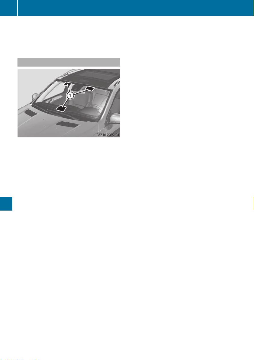
X
To remove: pull the floormat from retain-
ers ;.
X
Remove the floormat.
Infrared reflective windshield
The infrared reflecting glass prevents the vehi-
cle interior from becoming too hot. It also blocks
radio waves up into the gigahertz range.
To enable operation of radio-controlled equip-
ment, e.g. toll recording systems, areas on the
windshield are permeable to radio waves :. In
these areas, you can install radio-controlled sys-
tems.
These areas can best be seen from outside the
vehicle by observing the light reflected off the
windshield.
320
Features
Stowage and features

Engine compartment
Hood
Important safety notes
G
WARNING
If the hood is unlatched, it may open up when
the vehicle is in motion and block your view.
There is a risk of an accident.
Never unlatch the hood while driving. Before
every trip, ensure that the hood is locked.
G
WARNING
When opening and closing the hood, it may
suddenly fall into the closed position. There is
a risk of injury to persons within range of
movement of the hood.
Open and close the hood only when no one is
within its range of movement.
G
WARNING
Opening the hood when the engine is over-
heated or when there is a fire in the engine
compartment could expose you to hot gases
or other service products. There is a risk of
injury.
Let an overheated engine cool down before
opening the hood. If there is a fire in the
engine compartment, keep the hood closed
and contact the fire department.
G
WARNING
The engine compartment contains moving
components. Certain components, such as
the radiator fan, may continue to run or start
again suddenly when the ignition is off. There
is a risk of injury.
If you need to do any work inside the engine
compartment:
R
switch off the ignition
R
never reach into the area where there is a
risk of danger from moving components,
such as the fan rotation area
R
remove jewelry and watches
R
keep items of clothing and hair, for exam-
ple, away from moving parts
G
WARNING
The ignition system and the fuel injection sys-
tem work under high voltage. If you touch
components which are under voltage, you
could get an electric shock. There is a risk of
injury.
Never touch components of the ignition sys-
tem or fuel injection system when the ignition
is switched on.
Electrically live components include ignition
coils, spark plug connectors and the test socket.
Plug-in hybrid: be sure to read the separate
Operator's Manual. You could otherwise fail to
recognize dangers, e.g. due to high voltage.
Opening the hood
G
WARNING
Certain components in the engine compart-
ment, such as the engine, radiator and parts
of the exhaust system, can become very hot.
Working in the engine compartment poses a
risk of injury.
Where possible, let the engine cool down and
touch only the components described in the
following.
G
WARNING
When the hood is open and the windshield
wipers are set in motion, you can be injured by
the wiper linkage. There is a risk of injury.
Always switch off the windshield wipers and
the ignition before opening the hood.
!
Make sure that the windshield wipers are
not folded away from the windshield. You
could otherwise damage the windshield wip-
ers or the hood.
Engine compartment
321
Maintenance and care
Z
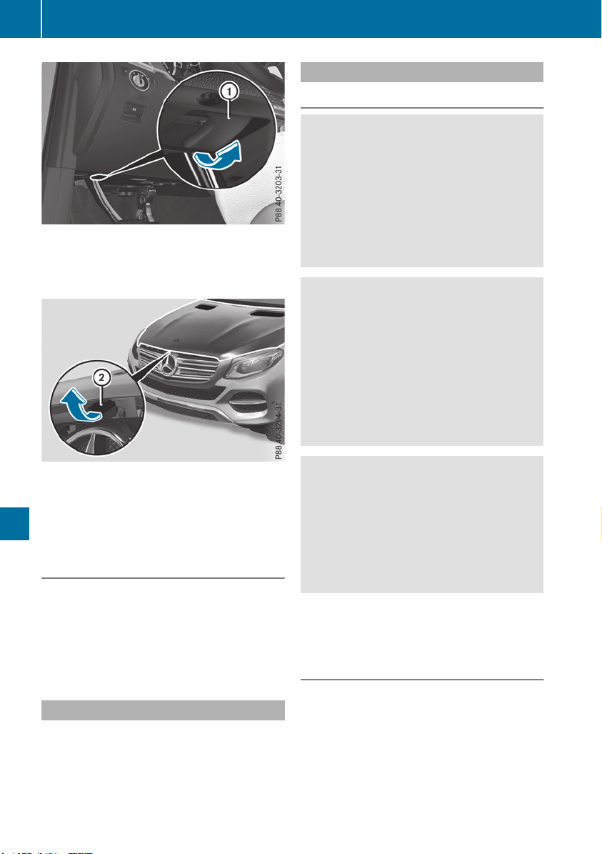
X
Make sure that the windshield wipers are
turned off.
X
Pull release lever : on the hood.
The hood is released.
X
Reach into the gap, pull hood catch handle ;
up and lift the hood.
If you lift the hood by approximately 15 in
(40 cm), the hood is opened and held open
automatically by the gas-filled strut.
Closing the hood
X
Lower the hood and let it fall from a height of
approximately 8 in (20 cm).
X
Check that the hood has engaged properly.
If the hood can be raised slightly, it is not
properly engaged. Open it again and close it
with a little more force.
Radiator
Vehicles with a diesel engine: do not cover
the radiator. such as with a thermal mat or
insect protection cover. Otherwise, the values of
the European on-board diagnostics may be
affected. Some of these readings are required
by law and must be accurate at all times.
Engine oil
Important safety notes
G
WARNING
Certain components in the engine compart-
ment, such as the engine, radiator and parts
of the exhaust system, can become very hot.
Working in the engine compartment poses a
risk of injury.
Where possible, let the engine cool down and
touch only the components described in the
following.
G
WARNING
Opening the hood when the engine is over-
heated or when there is a fire in the engine
compartment could expose you to hot gases
or other service products. There is a risk of
injury.
Let an overheated engine cool down before
opening the hood. If there is a fire in the
engine compartment, keep the hood closed
and contact the fire department.
G
WARNING
If engine oil comes into contact with hot com-
ponents in the engine compartment, it may
ignite. There is a risk of fire and injury.
Make sure that engine oil is not spilled next to
the filler neck. Let the engine cool down and
thoroughly clean the engine oil off the com-
ponents before starting the engine.
Plug-in hybrid: be sure to read the separate
Operator's Manual. You could otherwise fail to
recognize dangers, e.g. due to high voltage.
General notes
Depending on your driving style, the vehicle
consumes up to 0.9 US qt (0.8 liters) of oil per
600 miles (1,000 km). The oil consumption may
be higher than this when the vehicle is new or if
you frequently drive at high engine speeds.
Depending on the engine, the oil dipstick may be
in a different location.
322
Engine compartment
Maintenance and care
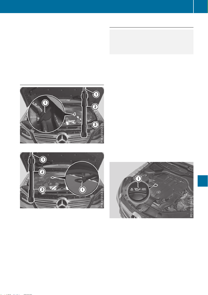
When checking the oil level:
R
park the vehicle on a level surface.
R
the engine should be switched off for approx-
imately five minutes if the engine is at normal
operating temperature.
R
if the engine is not at normal operating tem-
perature, e.g. if the engine was only started
briefly, wait about 30 minutes before carrying
out the measurement.
Checking the oil level using the oil dip-
stick
Example: vehicles with a gasoline engine
Example: vehicles with a diesel engine
X
Pull oil dipstick : out of the dipstick tube.
X
Wipe off oil dipstick :.
X
Slowly slide oil dipstick : into the guide tube
to the stop, and take it out again.
If the level is between MIN mark = and MAX
mark ;, the oil level is correct.
X
If the oil level has dropped to MIN mark = or
below, add 1.1 US qt (1.0 liter) engine oil.
Adding engine oil
H
Environmental note
When adding oil, take care not to spill any. If
oil enters the soil or waterways, it is harmful to
the environment.
!
Use only engine oils and oil filters that are
approved for vehicles with a service system. A
list of the engine oils and oil filters that have
been tested and approved in accordance with
Mercedes-Benz Specifications for Service
Products is available at any authorized
Mercedes-Benz Center.
The following cause engine failure or damage
to the exhaust system:
R
Use of engine oils and oil filters that have
not been expressly approved for the service
system
R
Replacement of engine oil and oil filter after
the replacement interval specified by the
service system has expired
R
Use of engine oil additives
!
Do not add too much oil. adding too much
engine oil can result in damage to the engine
or to the catalytic converter. Have excess
engine oil siphoned off.
Example: engine oil cap
X
Turn cap : counter-clockwise and remove it.
X
Add engine oil.
If the oil level is at or below the MIN mark on
the oil dipstick, add 1.1 US qt (1.0 liter) of
engine oil.
X
Replace cap : on the filler neck and tighten
clockwise.
Ensure that the cap locks into place securely.
X
Check the oil level again with the oil dipstick
(Y page 323).
Engine compartment
323
Maintenance and care
Z
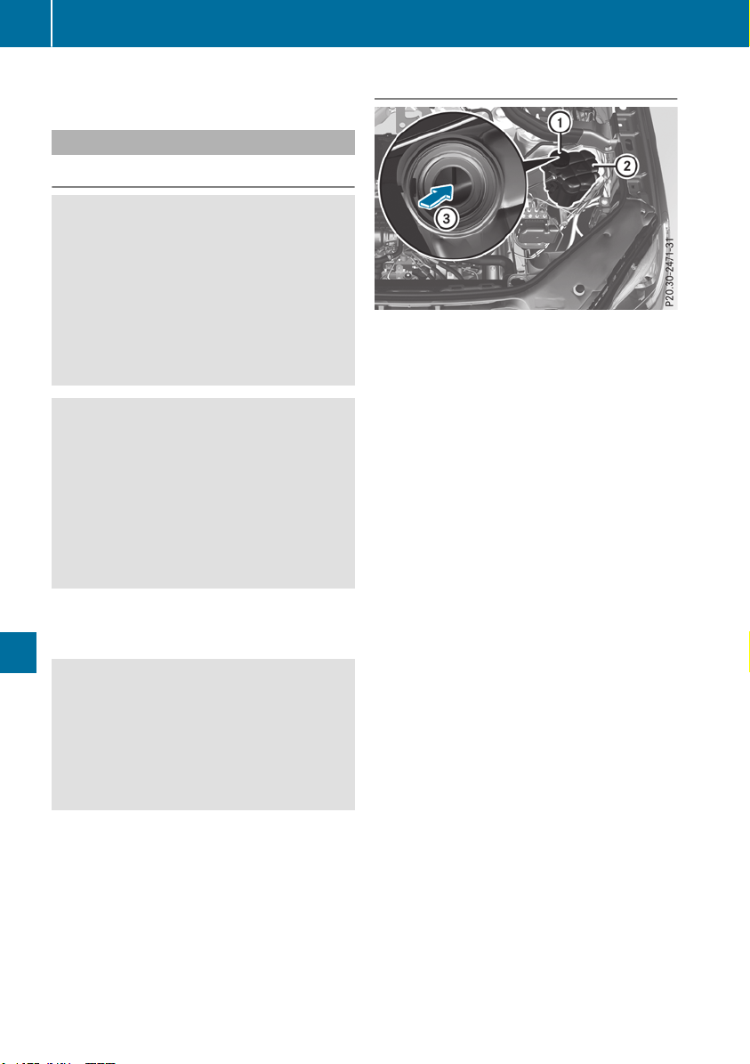
Further information on engine oil (Y page 387).
Additional service products
Important safety notes
G
WARNING
Certain components in the engine compart-
ment, such as the engine, radiator and parts
of the exhaust system, can become very hot.
Working in the engine compartment poses a
risk of injury.
Where possible, let the engine cool down and
touch only the components described in the
following.
G
WARNING
The cooling system is pressurized, particularly
when the motor is warm. If you open the cap,
you could be scalded if hot coolant sprays out.
There is a risk of injury.
Let the engine cool down before you open the
cap. Wear protective gloves and protective
eyewear when opening. Open the cap slowly
to release pressure.
The coolant level may only be checked and cool-
ant refilled when the engine and engine cooling
system have cooled down.
G
WARNING
Windshield washer concentrate could ignite if
it comes into contact with hot engine compo-
nents or the exhaust system. There is a risk of
fire and injury.
Make sure that no windshield washer con-
centrate is spilled next to the filler neck.
Checking coolant level
X
Park the vehicle on a level surface.
Only check the coolant level when the vehicle
is on a level surface and the engine has cooled
down.
X
Turn the SmartKey to position 2 in the igni-
tion lock (Y page 135).
On vehicles with KEYLESS-GO, press the
Start/Stop button twice (Y page 137).
X
Check the coolant temperature gauge in the
multifunction display.
The coolant temperature must be below
158 ‡ (70 †).
X
Turn the SmartKey to position in the ignition
lock u (Y page 135).
X
On vehicles with KEYLESS-GO, press the
Start/Stop button (Y page 137).
X
Press the Start/Stop button (Y page 137).
X
Slowly turn cap : half a turn counter-clock-
wise and allow excess pressure to escape.
X
Turn cap : further counter-clockwise and
remove it.
If the coolant is at the level of marker bar =
in the filler neck when cold, there is enough
coolant in coolant expansion tank ;.
If the coolant level is approximately 0.6 in
(1.5 cm) above marker bar = in the filler neck
when warm, there is enough coolant in expan-
sion tank ;.
X
If necessary, add coolant that has been tested
and approved by Mercedes-Benz.
X
Replace cap : and turn it clockwise as far as
it will go.
For further information on coolant, see
(Y page 388).
324
Engine compartment
Maintenance and care
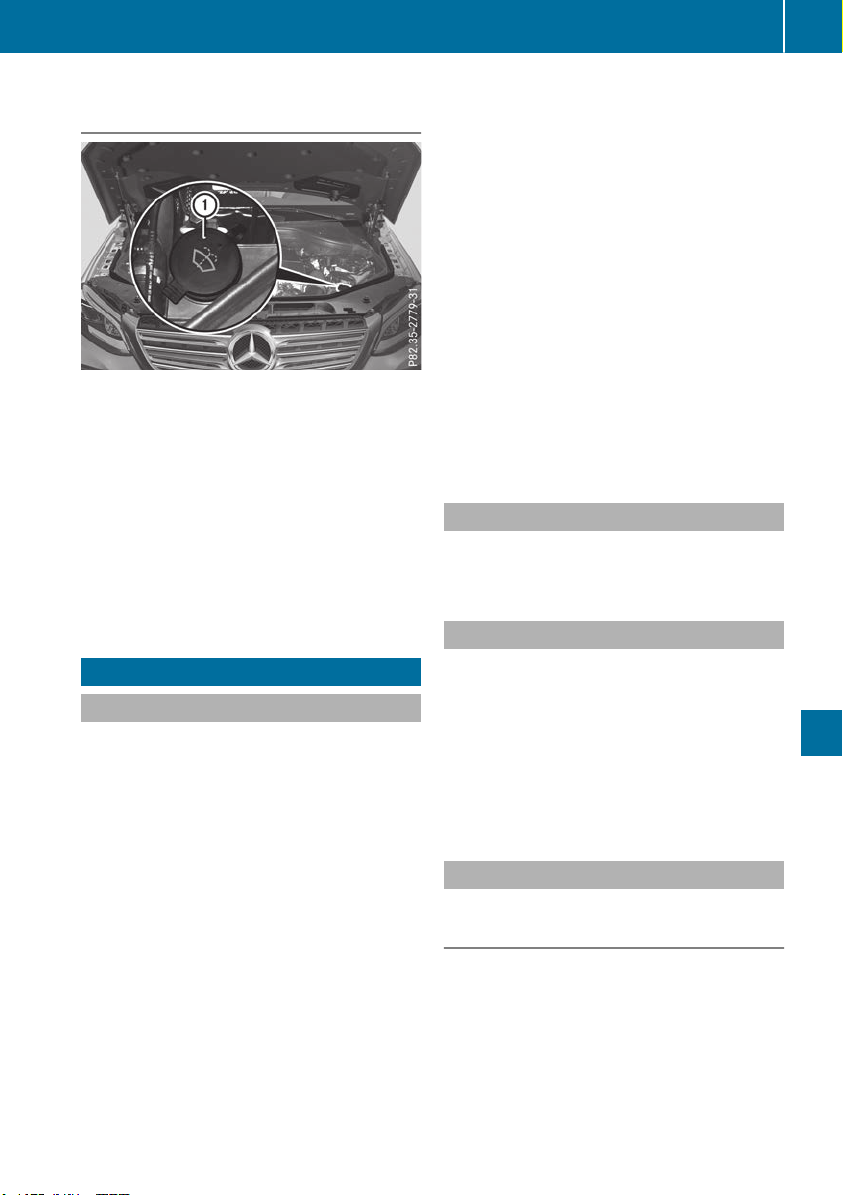
Adding washer fluid to the windshield
washer system
Example: washer fluid reservoir
X
To open: pull cap : upwards by the tab.
X
Add the premixed washer fluid.
X
To close: press cap : onto the filler neck
until it engages.
If the washer fluid level drops below the recom-
mended minimum of 1 liter, a message appears
in the multifunction display prompting you to
add washer fluid (Y page 272).
Further information on windshield washer fluid
(Y page 389).
ASSYST PLUS
Service message
i
If the scheduled service intervals are excee-
ded, this may result in damage to the vehicle.
You can obtain up-to-date information concern-
ing the servicing of your vehicle from a qualified
specialist workshop, e.g. an authorized
Mercedes-Benz Center or at
http://www.mbusa.com (USA only).
i
The ASSYST PLUS service interval display
does not show any information on the engine
oil level. Observe the notes on the engine oil
level (Y page 322).
The multifunction display shows a service mes-
sage for several seconds, e.g.:
R
Service A in .. DaysService A in .. Days
R
Service A DueService A Due
R
Service A Exceeded by .. DaysService A Exceeded by .. Days
Depending on the operating conditions of the
vehicle, the remaining time or distance until the
next service due date is displayed.
The letter AA or BB, possibly in connection with a
number or another letter, shows the type of ser-
vice. AA stands for a minor service and BB for a
major service.
Further information can be obtained at a quali-
fied specialist workshop.
The ASSYST PLUS service interval display does
not take into account any periods of time during
which the battery is disconnected.
Maintaining the time-dependent service sched-
ule:
X
Note down the service due date displayed in
the multifunction display before disconnect-
ing the battery.
or
X
After reconnecting the battery, subtract the
battery disconnection periods from the ser-
vice date shown on the display.
Hiding a service message
X
Press the % or a button on the steering
wheel.
Displaying service messages
X
Switch on the ignition.
X
Press the = or ; button on the steering
wheel to select the Serv.Serv. menu.
X
Press the 9 or : button to select the
ASSYSTASSYST PLUSPLUS submenu and confirm by press-
ing the a button.
The service due date appears in the multi-
function display.
Information about Service
Resetting the ASSYST PLUS service
interval display
!
If the ASSYST PLUS service interval display
has been inadvertently reset, this setting can
be corrected at a qualified specialist work-
shop.
Have service work carried out as described in
the Maintenance Booklet. This may otherwise
lead to increased wear and damage to the
major assemblies or the vehicle.
ASSYST PLUS
325
Maintenance and care
Z

A qualified specialist workshop will reset the
ASSYST PLUS service interval display after the
service work has been carried out. You can also
obtain further information on maintenance
work, for example.
Special service requirements
The specified maintenance interval takes only
the normal operation of the vehicle into
account. Under increased load on the vehicle,
maintenance work must be carried out more
frequently, for example:
R
Regular city driving with frequent intermedi-
ate stops
R
If the vehicle is primarily used to travel short
distances
R
Use in mountainous terrain or on poor road
surfaces
R
If the engine is often left idling for long periods
Under these or similar conditions, have, for
example, the air filter, engine oil and oil filter
replaced or changed more frequently. Under
arduous operating conditions, the tires must be
checked more often. Further information can be
obtained at a qualified specialist workshop.
Driving abroad
An extensive Mercedes-Benz Service network is
also available in other countries. You can obtain
further information from any authorized
Mercedes-Benz Center.
Care
General notes
H
Environmental note
Dispose of empty packaging and cleaning
cloths in an environmentally responsible man-
ner.
!
When cleaning your car, do not use:
R
dry, coarse or hard cloths
R
abrasive cleaning agents
R
solvents
R
cleaning agents containing solvents
Do not scrub.
Do not touch the surfaces and films with hard
objects, e.g. rings or ice scrapers. Otherwise,
you may scratch or damage the surfaces and
films.
!
Do not park your vehicle for a long period of
time directly after cleaning, particularly after
cleaning the wheel rim with wheel cleaner.
Wheel cleaner can lead to the increased cor-
rosion of the brake discs and pads. Therefore,
drive for a few minutes after cleaning. By
heating up the brakes, the brake discs and
pads dry. The vehicle can then be parked for a
long period of time.
Regular care of your vehicle is a condition for
retaining the quality in the long term.
Use care products and cleaning agents recom-
mended and approved by Mercedes-Benz.
Washing the vehicle and cleaning the
paintwork
Automatic car wash
G
WARNING
Braking efficiency is reduced after washing
the vehicle. There is a risk of an accident.
After the vehicle has been washed, brake
carefully while paying attention to the traffic
conditions until full braking power is restored.
!
Before driving into an automatic car wash,
make sure that it is suitable for the dimen-
sions of the vehicle. In particular, make sure
that:
R
there is enough ground clearance between
the vehicle underbody and the guide rails of
the automatic car wash.
R
the clearance width of the automatic car
wash is sufficient, particularly the width of
the guide rails.
R
you enter the automatic car wash straight
and in the center of the guide rails in order
to avoid damaging the tires or wheel rims.
Fold in the exterior mirrors before the vehicle
is washed. The exterior mirrors could other-
wise be damaged.
!
When Active Distance Assist DISTRONIC or
the HOLD function is activated, the vehicle
brakes automatically in certain situations.
326
Care
Maintenance and care

To avoid damage to the vehicle, deactivate
Active Distance Assist DISTRONIC and the
HOLD function in the following or similar sit-
uations:
R
when towing the vehicle
R
in the car wash
!
Never clean your vehicle in a Touchless
Automatic Car Wash as these use special
cleaning agents. These cleaning agents can
damage the paintwork or plastic parts.
!
Make sure that:
R
the side windows and the sliding sunroof
are fully closed.
R
that the blower of the ventilation/heating
system is switched off (OFF button has
been pressed).
R
the windshield wiper switch is at position
g.
The vehicle may otherwise be damaged.
!
In car washes with a towing mechanism,
make sure that the automatic transmission is
in transmission position i; otherwise, the
vehicle could be damaged.
R
Vehicles with a SmartKey:
Do not remove the SmartKey from the igni-
tion lock. Do not open the driver's door or
front-passenger door when the engine is
switched off. Otherwise, the automatic
transmission selects park position j auto-
matically and locks the wheels. You can
prevent this by shifting the automatic trans-
mission to i beforehand.
R
Vehicles with KEYLESS-GO:
Do not open the driver's door or front-
passenger door when the engine is
switched off. Otherwise, the automatic
transmission selects park position j auto-
matically and locks the wheels.
Observe the following to make sure that the
automatic transmission stays in position i:
X
Make sure the vehicle is stationary and the
ignition is switched off.
X
Turn the SmartKey to position in the ignition
lock 2 (Y page 135).
Use the SmartKey instead of the Start/Stop
button on vehicles with KEYLESS-GO.
X
Depress and hold the brake pedal.
X
Shift the automatic transmission to position
i.
X
Release the brake pedal.
X
Release the electric parking brake.
X
Switch off the ignition and leave the SmartKey
in the ignition lock.
You can wash the vehicle in an automatic car
wash from the very start.
If the vehicle is very dirty, pre-wash it before
cleaning it in an automatic car wash.
After using an automatic car wash, wipe off wax
from the windshield and the wiper blades. This
will prevent smears and reduce wiping noises
caused by residue on the windshield.
Washing by hand
In some countries, washing by hand is only
allowed at specially equipped washing bays.
Observe the legal requirements in all countries
concerned.
X
Do not use hot water and do not wash the
vehicle in direct sunlight.
X
Use a soft sponge to clean.
X
Use a mild cleaning agent, such as a car
shampoo approved by Mercedes-Benz.
X
Thoroughly hose down the vehicle with a gen-
tle jet of water.
X
Do not point the water jet directly towards the
air inlets.
X
Use plenty of water and rinse out the sponge
frequently.
X
Rinse the vehicle with clean water and dry
thoroughly with a chamois.
X
Do not let the cleaning agent dry on the paint-
work.
When using the vehicle in winter, remove all
traces of road salt deposits carefully and as
soon as possible.
Power washers
G
WARNING
The water jet from a circular jet nozzle (dirt
blasters) can cause invisible exterior damage
to the tires or chassis components. Compo-
nents damaged in this way may fail unexpect-
edly. There is a risk of an accident.
Do not use power washers with circular jet
nozzles to clean the vehicle. Have damaged
Care
327
Maintenance and care
Z

tires or chassis components replaced imme-
diately.
!
Always maintain a distance of at least 12 in
(30 cm) between the vehicle and the power
washer nozzle. Information about the correct
distance is available from the equipment
manufacturer.
Move the power washer nozzle around when
cleaning your vehicle.
Do not aim directly at any of the following:
R
Tires
R
Door gaps, roof gaps, joints, etc.
R
Electrical components
R
Battery
R
Plug-type couplings
R
Light bulbs
R
Seals
R
Trim elements
R
Ventilation slots
Damaged seals or electrical components can
lead to leaks or failures.
!
Vehicles with decorative foil: parts of your
vehicle are covered with decorative foil. Main-
tain a distance of at least 27.5 in (70 cm)
between the foil-wrapped parts of the vehicle
and the nozzle of the high pressure cleaner.
Information about the correct distance is
available from the equipment manufacturer.
Move the power washer nozzle around when
cleaning your vehicle.
The water temperature of the high-pressure
cleaner must not exceed 140 °F (60 °C).
Cleaning the paintwork
!
Do not affix:
R
stickers
R
films
R
magnetic plates or similar items
to painted surfaces. You could otherwise
damage the paintwork.
Scratches, corrosive deposits, areas affected by
corrosion and damage caused by inadequate
care cannot always be completely repaired. In
such cases, visit a qualified specialist workshop.
X
Remove dirt immediately, where possible,
while avoiding rubbing too hard.
X
Soak insect remains with insect remover and
rinse off the treated areas afterwards.
X
Soak bird droppings with water and rinse off
the treated areas afterwards.
X
Remove tree resin, oils, fuels and greases by
rubbing gently with a cloth soaked in petro-
leum ether or lighter fluid
X
Remove coolant and brake fluid with a moist
cloth and clear water.
X
Use tar remover to remove tar stains.
X
Use silicone remover to remove wax.
If water no longer forms "beads" on the paint
surface, use the paint care products recommen-
ded and approved by Mercedes-Benz. This is the
case approximately every three to five months,
depending on the climate conditions and the
care product used.
If dirt has penetrated the paint surface or if the
paint has become dull, the paint cleaner recom-
mended and approved by Mercedes-Benz
should be used.
Do not use these care products in the sun or on
the hood while the hood is hot.
X
Use a suitable touch-up stick, e.g. MB Touch-
Up Stick, to repair slight damage to the paint-
work quickly and provisionally.
Matte finish care
!
Never polish the vehicle or the light alloy
wheels. Polishing causes the finish to shine.
!
The following can give the paint a glossy
appearance and thus reduce the matt effect:
R
Rubbing hard with unsuitable agents
R
Washing the vehicle in direct sunlight
!
Never use paint cleaner, buffing or polishing
products, or gloss preserver, e.g. wax, for the
purpose of paintwork care. These products
are only suitable for high-gloss surfaces. Their
use on vehicles with matte paintwork leads to
considerable surface damage or, more spe-
cifically, to shiny, spotted areas.
Always have paintwork repairs carried out at a
qualified specialist workshop.
!
Only use automatic car washes which cor-
respond to the latest technological stand-
ards. Never use wash programs which finish
by treating the vehicle with hot wax.
328
Care
Maintenance and care

Observe these notes if your vehicle has a clear
matte finish. This will help you to avoid damage
to the paintwork due to incorrect treatment.
These notes also apply to light alloy wheels with
a clear matte finish.
i
Use only insect remover and car shampoo
from the range of recommended and
approved Mercedes-Benz care products.
Cleaning the decorative film
!
The following may have an effect on the ser-
vice life and color of decorative film:
R
sunlight
R
temperature, e.g. hot-air fan
R
weather conditions
R
stone impacts and dirt
R
chemical cleaning agents
R
greasy substances
!
Do not use any types of polish on matt dec-
orative film. Polishing surfaces covered with
film gives it a shiny finish.
!
Do not treat matt or structured decorative
film with wax. This may lead to marks that
cannot be removed.
Observe the notes in the matte finish paintwork
care and treatment chapter (Y page 328).
These notes also apply for matte decorative
films.
To clean, use plenty of water and a mild cleaning
agent without additional or abrasive products,
e.g. a car shampoo approved for Mercedes-
Benz.
X
Dry vehicles covered with film using a soft,
absorbent cloth after every wash.
Water marks could otherwise form.
Scratches, corrosive deposits, areas affected by
corrosion and damage caused by inadequate
care cannot always be completely repaired. In
such cases, visit a qualified specialist workshop.
X
Remove dirt immediately, where possible,
while avoiding rubbing too hard.
The decorative film may be irreparably dam-
aged.
X
Soak insect remains with insect remover and
rinse off the treated areas afterwards.
X
Soak bird droppings with water and rinse off
the treated areas afterwards.
The Paint Cleaner cleaning product, which has
been approved and recommended for
Mercedes-Benz, should be used when dirt has
penetrated the decorative film surface or the
decorative film has become dull.
The manufacturer can provide you with infor-
mation on special care and cleaning products.
Surfaces covered with a decorative film may,
once a decorative film has been removed, show
visual differences from the surfaces that were
not protected by a decorative film.
i
Have work or repairs on decorative film car-
ried out at a qualified specialist workshop.
Mercedes-Benz recommends that you use an
authorized Mercedes-Benz Center for this
purpose.
Cleaning the vehicle parts
Cleaning the wheels
G
WARNING
The water jet from a circular jet nozzle (dirt
blasters) can cause invisible exterior damage
to the tires or chassis components. Compo-
nents damaged in this way may fail unexpect-
edly. There is a risk of an accident.
Do not use power washers with circular jet
nozzles to clean the vehicle. Have damaged
tires or chassis components replaced imme-
diately.
!
Do not use acidic wheel cleaning products
to remove brake dust. This could damage
wheel bolts and brake components.
!
Do not park your vehicle for a long period of
time directly after cleaning, particularly after
cleaning the wheel rim with wheel cleaner.
Wheel cleaner can lead to the increased cor-
rosion of the brake discs and pads. Therefore,
drive for a few minutes after cleaning. By
heating up the brakes, the brake discs and
pads dry. The vehicle can then be parked for a
long period of time.
Care
329
Maintenance and care
Z

Cleaning the windows
G
WARNING
You could become trapped by the windshield
wipers if they start moving while cleaning the
windshield or wiper blades. There is a risk of
injury.
Always switch off the windshield wipers and
the ignition before cleaning the windshield or
wiper blades.
!
Do not use dry cloths, abrasive products,
solvents or cleaning agents containing sol-
vents to clean the inside of the windows. Do
not touch the insides of the windows with
hard objects, e.g. an ice scraper or ring. There
is otherwise a risk of damaging the windows.
!
Clean the water drainage channels of the
windshield and the rear window at regular
intervals. Deposits such as leaves, petals and
pollen may under certain circumstances pre-
vent water from draining away. This can lead
to corrosion damage and damage to elec-
tronic components.
X
Clean the inside and outside of the windows
with a damp cloth and a cleaning product that
is recommended and approved by Mercedes-
Benz.
Cleaning wiper blades
G
WARNING
You could become trapped by the windshield
wipers if they start moving while cleaning the
windshield or wiper blades. There is a risk of
injury.
Always switch off the windshield wipers and
the ignition before cleaning the windshield or
wiper blades.
!
Do not pull the wiper blade. Otherwise, the
wiper blade could be damaged.
!
Do not clean wiper blades too often and do
not rub them too hard. Otherwise, the graph-
ite coating could be damaged. This could
cause wiper noise.
!
Hold the wiper arm securely when folding
back. The windshield could be damaged if the
wiper arm smacks against it suddenly.
X
Fold the windshield wiper arms away from the
windshield (Y page 118).
X
Carefully clean the wiper blades with a damp
cloth.
X
Fold the windshield wiper arms back again
before switching on the ignition.
Cleaning the exterior lighting
!
Only use cleaning agents or cleaning cloths
which are suitable for plastic light lenses.
Unsuitable cleaning agents or cleaning cloths
could scratch or damage the plastic light len-
ses.
X
Clean the plastic lenses of the exterior light-
ing using a wet sponge and a mild cleaning
agent, e. g. Mercedes-Benz car shampoo or
cleaning cloths.
Cleaning the mirror turn signals
!
Only use cleaning agents or cleaning cloths
that are suitable for plastic lenses. Unsuitable
cleaning agents or cleaning cloths could
scratch or damage the plastic lenses of the
mirror turn signals.
X
Clean the plastic lenses of the mirror turn sig-
nals in the exterior mirror housing using a wet
sponge and mild cleaning agent, e.g.
Mercedes-Benz car shampoo or cleaning
cloths.
Cleaning the side running board
!
Do not clean the aluminum insert of the side
running board with alkaline or acid-based
cleaning agents, such as wheel cleaner. Do
not use acidic wheel cleaners to remove
brake dust. The aluminum inserts could oth-
erwise be damaged.
Cleaning the sensors
!
If you clean the sensors with a power
washer, make sure that you keep a distance
of at least 11.8 in (30 cm) between the vehicle
and the power washer nozzle. Information
about the correct distance is available from
the equipment manufacturer.
330
Care
Maintenance and care
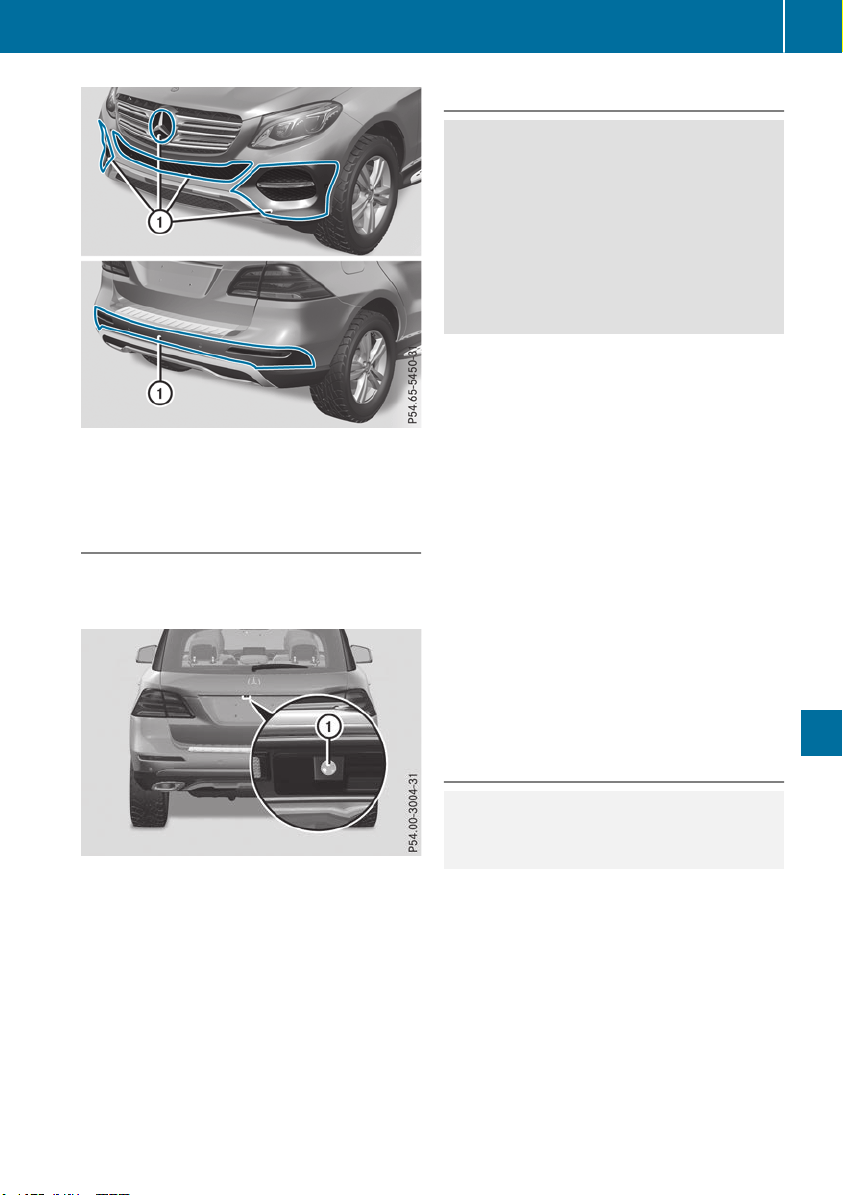
X
Clean sensors : of the driving systems with
water, car shampoo and a soft cloth.
Cleaning the rear view camera and 360°
camera
!
Do not clean the camera lens and the area
around the rear view camera or 360° camera
with a power washer.
X
Make sure that the vehicle is stationary and
the SmartKey is in position 2 in the ignition
lock.
X
Open the camera cover for cleaning via the
multimedia system (see Digital Operator's
Manual).
X
To clean the camera: use clean water and a
soft cloth to clean the camera lens :.
360° camera: if you drive at speeds above
20 mph (30 km/h) or with the SmartKey in posi-
tion u or 1 in the ignition lock, the cover of
the 360° camera closes.
Cleaning the exhaust pipe
G
WARNING
The exhaust tail pipe and tail pipe trim can
become very hot. If you come into contact
with these parts of the vehicle, you could burn
yourself. There is a risk of injury.
Always be particularly careful around the
exhaust tail pipe and the tail pipe trim. Allow
these components to cool down before touch-
ing them.
!
Vehicles with black exhaust pipes: black
chromed screens should not be polished with
a chrome polish. They will otherwise lose their
black shine. For optimal care, the screens
should be rubbed with a lightly oiled cloth
after every car wash. Commercially available
engine and care oils are suitable for this.
For heavier soiling, you can apply a fine paint-
work polish with a microfiber cloth. Remove
the excess polish residue after polishing.
Impurities combined with the effects of road grit
and corrosive environmental factors may cause
flash rust to form on the surface. You can
restore the original shine of the exhaust pipe by
cleaning it regularly, especially in winter and
after washing.
X
Clean the exhaust pipe with a chrome care
product tested and approved by Mercedes-
Benz.
Cleaning the trailer tow hitch
H
Environmental note
Dispose of rags soaked in oil and grease in an
environmentally responsible manner.
!
Do not clean the ball coupling with a power
washer. Do not use solvents.
!
Please note the care instructions in the
trailer coupling manufacturer's operating
instructions.
Care
331
Maintenance and care
Z
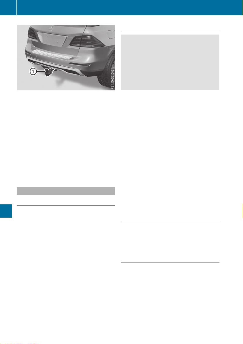
The ball coupling must be cleaned if it becomes
dirty or corroded.
X
Remove rust on the ball of the ball coupling,
e.g. with a wire brush.
X
Remove dirt with a clean, lint-free cloth or a
brush.
X
After cleaning, lightly oil or grease ball cou-
pling :.
X
Check that the vehicle's trailer tow hitch is
working properly.
i
You can also have the maintenance work on
the ball coupling and the trailer tow hitch car-
ried out by a qualified specialist workshop.
Interior care
Cleaning the display
!
For cleaning, do not use any of the following:
R
alcohol-based thinner or gasoline
R
abrasive cleaning agents
R
commercially-available household cleaning
agents
These may damage the display surface. Do
not put pressure on the display surface when
cleaning. This could lead to irreparable dam-
age to the display.
X
Before cleaning the display, make sure that it
is switched off and has cooled down.
X
Clean the display surface using a commer-
cially available microfiber cloth and TFT/LCD
display cleaner.
X
Dry the display surface using a dry microfiber
cloth.
Cleaning the plastic trim
G
WARNING
Care products and cleaning agents containing
solvents cause surfaces in the cockpit to
become porous. As a result, plastic parts may
come loose in the event of air bag deploy-
ment. There is a risk of injury.
Do not use any care products and cleaning
agents to clean the cockpit.
!
Never attach the following to plastic surfa-
ces:
R
stickers
R
films
R
perfume oil container or similar
You could otherwise damage the plastic.
!
Do not allow cosmetics, insect repellent or
sunscreen to come into contact with the plas-
tic trim. This maintains the high-quality look of
the surfaces.
X
Wipe the plastic trim with a damp, lint-free
cloth, e.g. a microfiber cloth.
X
Heavy soiling: use care and cleaning prod-
ucts recommended and approved by
Mercedes-Benz.
The surface may change color temporarily.
Wait until the surface is dry again.
Cleaning the steering wheel and gear or
selector lever
X
Thoroughly wipe with a damp cloth or use
leather care agents that have been recom-
mended and approved by Mercedes-Benz.
Cleaning genuine wood and trim ele-
ments
!
Do not use solvent-based cleaning agents
such as tar remover, wheel cleaners, polishes
or waxes. There is otherwise a risk of damag-
ing the surface.
!
Do not use chrome polish on trim pieces.
The trim pieces have a chrome look but are
mostly made of anodized aluminum and can
lose their shine if chrome polish is used. Use
a damp, lint-free cloth instead when cleaning
the trim pieces.
332
Care
Maintenance and care

If the chrome-plated trim pieces are very
dirty, you can use a chrome polish. If you are
unsure as to whether the trim pieces are
chrome-plated or not, consult an authorized
Mercedes-Benz Center.
X
Wipe the wooden trim and trim pieces with a
damp, lint-free cloth, e.g. a microfiber cloth.
X
Heavy soiling: use car care and cleaning
products recommended and approved by
Mercedes-Benz.
Cleaning the seat covers
General notes
!
Do not use a microfiber cloth to clean covers
made out of real leather, artificial leather or
DINAMICA. If used often, these can damage
the cover.
i
Note that regular care is essential to ensure
that the appearance and comfort of the cov-
ers is retained over time.
Genuine leather seat covers
!
To retain the natural appearance of the
leather, observe the following cleaning
instructions:
R
Clean genuine leather covers carefully with
a damp cloth and then wipe the covers
down with a dry cloth.
R
Make sure that the leather does not
become soaked. It may otherwise become
rough and cracked.
R
Only use leather care agents that have
been tested and approved by Mercedes-
Benz. You can obtain these from a qualified
specialist workshop.
Leather is a natural product.
It exhibits natural surface characteristics, for
example:
R
differences in the texture
R
marks caused by growth and injury
R
slight nuances of color
These are characteristics of leather and not
material defects.
Seat covers of other materials
!
Observe the following when cleaning:
R
clean artificial leather covers with a cloth
moistened with a solution containing 1%
detergent (e.g. dish washing liquid).
R
clean cloth covers with a microfiber cloth
moistened with a solution containing 1%
detergent (e.g. dish washing liquid). Rub
carefully and always wipe entire seat sec-
tions to avoid leaving visible lines. Leave
the seat to dry afterwards. Cleaning results
depend on the type of dirt and how long it
has been there.
R
clean DINAMICA covers with a damp cloth.
Make sure that you wipe entire seat sec-
tions to avoid leaving visible lines.
Cleaning the seat belts
G
WARNING
Seat belts can become severely weakened if
bleached or dyed. This could cause the seat
belts to tear or fail, for instance, in the event of
an accident. This poses an increased risk of
injury or fatal injury.
Never bleach or dye the seat belts.
!
Do not clean the seat belts using chemical
cleaning agents. Do not dry the seat belts by
heating at temperatures above 176 ‡(80 †)
or in direct sunlight.
X
Use clean, lukewarm water and soap solution.
Cleaning the headliner and carpets
X
Headliner: if it is very dirty, use a soft brush or
dry shampoo.
X
Carpets: use the carpet and textile cleaning
agents recommended and approved by
Mercedes-Benz.
Care
333
Maintenance and care
Z
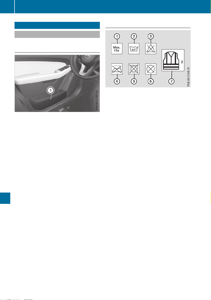
Where will I find...?
Reflective safety jacket
Removing/replacing the reflective
safety jacket
The reflective safety jackets are located in front
door stowage compartments :. Reflective
safety jackets can also be stored in the rear door
stowage compartments.
X
To remove: pull out the safety jacket bag
containing the reflective safety jacket.
X
Open the safety jacket bag and pull out the
reflective safety jacket.
X
To stow: fold the reflective safety jacket, roll
it up and stow it in the safety jacket bag.
X
Replace the safety jacket bag in stowage
compartment :.
i
Remove a new reflective safety jacket from
its packaging material before sliding it into
the stowage compartment. The packaging
material may otherwise cause it to slip out or
make removing it difficult.
Observe the legal requirements in each country.
Information on reflective safety jackets
:
Maximum number of washes
;
Maximum wash temperature
=
Do not bleach
?
Do not iron
A
Do not use a laundry dryer
B
Do not dry-clean
C
This is a class 2 vest
R
The reflective safety jackets meet the require-
ments defined by the legal standard only:
-
if the correct size is used and
-
if the reflective safety jackets are correctly
fastened
R
Before use, ensure that the reflective safety
jackets are clean and intact. The special prop-
erties may otherwise be compromised.
R
The reflective safety jackets should be stored
in their original packaging in a dry place away
from sources of heat and light.
R
The maximum number of washes specified is
not the only factor influencing the life span of
the reflective safety jackets. Their life span
also depends on use, care, storage, etc.
R
The reflective safety jackets should be dis-
posed of and replaced with new ones:
-
after 15 washes, and/or
-
if the reflective strips have become
scratched, and/or
-
if the backing material and/or reflective
strips have become soiled and cannot be
cleaned off, and/or
-
if the fluorescence has faded e.g. due to the
effects of sunlight
R
Dispose of reflective safety jackets in an envi-
ronmentally responsible manner. To do so,
contact your local waste disposal company.
334
Where will I find...?
Breakdown assistance
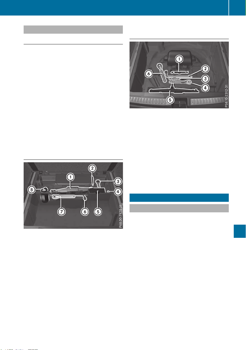
Vehicle tool kit
General notes
The vehicle tool kit can be found in the stowage
well under the cargo compartment floor.
Apart from certain country-specific variations,
the vehicles are not equipped with a tire-change
tool kit. Some tools for changing a wheel are
specific to the vehicle. For more information on
which tools are required to perform a wheel
change on your vehicle, consult a qualified spe-
cialist workshop.
Necessary tire-changing tools can include, for
example:
R
jack
R
wheel chock
R
lug wrench
R
ratchet wrench
R
alignment bolt
Vehicles with a TIREFIT kit
:
Jack
;
Folding wheel chock
=
Towing eye
?
Alignment bolt
A
Tire inflation compressor
B
Lug wrench
C
Ratchet wrench
D
Tire sealant filler bottle
X
Open the tailgate.
X
Lift the cargo compartment floor up
(Y page 303).
X
Use the TIREFIT kit (Y page 337).
Vehicles with a "Minispare" emergency
spare wheel
:
Folding wheel chock
;
Lug wrench
=
Alignment bolt
?
Towing eye
A
Jack
B
Ratchet wrench
X
Open the tailgate.
X
Lift the cargo compartment floor up
(Y page 303).
X
Remove the "Minispare" emergency spare
wheel (Y page 377).
Flat tire
Preparing the vehicle
Your vehicle may be equipped with:
R
MOExtended tires (tires with run-flat proper-
ties)
Vehicle preparation is not necessary on vehi-
cles with MOExtended tires.
R
a TIREFIT kit (Y page 335)
R
an emergency spare wheel (only for certain
countries)
Vehicles with an mbrace system (USA only)
which are not equipped with a TIREFIT kit: in the
event of a flat tire, contact the Customer Assis-
tance Center for the mbrace emergency call
system (Y page 310).
Information on changing and mounting wheels
(Y page 371).
X
Stop the vehicle on solid, non-slippery and
level ground, as far away as possible from
traffic.
X
Switch on the hazard warning lamps.
Flat tire
335
Breakdown assistance

X
Secure the vehicle against rolling away
(Y page 156).
X
If possible, bring the front wheels into the
straight-ahead position.
X
Vehicles with the AIRMATIC package:
make sure that the normal vehicle level is
selected (Y page 185).
X
Vehicles with the Off-Road Engineering
package: make sure that the normal vehicle
level is selected (Y page 179).
X
Switch off the engine.
X
Vehicles without KEYLESS-GO: remove the
SmartKey from the ignition lock.
X
Vehicles with KEYLESS-GO: open the driv-
er's door.
The vehicle electronics are now in position
u. This means no SmartKey is in the ignition
lock.
X
Vehicles with KEYLESS-GO: remove the
Start/Stop button from the ignition lock
(Y page 135).
X
Make sure that the engine cannot be started
via your smartphone (Y page 137).
X
Make sure that the passengers are not endan-
gered as they do so. Make sure that no one is
near the danger area while a wheel is being
changed. Anyone who is not directly assisting
in the wheel change should, for example,
stand behind the barrier.
X
Get out of the vehicle. Pay attention to traffic
conditions when doing so.
X
Close the driver's door.
X
Unload heavy luggage.
i
Only operate the tire inflation compressor
using a 12 V socket, even if the ignition is
turned off (Y page 308).
An emergency cut-out ensures that the on-
board voltage does not drop too low. If the on-
board voltage is too low, the power to the
sockets is automatically cut. This ensures
that there is sufficient power to start the
engine.
MOExtended tires (tires with run-flat
properties)
General notes
With MOExtended tires (tires with run flat char-
acteristics), you can continue to drive your vehi-
cle even if there is a total loss of pressure in one
or more tires. The affected tire must not show
any clearly visible damage.
You can recognize a MOExtended tire by the
MOExtended marking which appears on the
sidewall of the tire. You will find this marking
next to the tire size designation, the load-bear-
ing capacity and the speed index (Y page 366).
MOExtended tires may only be used in conjunc-
tion with an active tire pressure loss warning
system or with an active tire pressure monitor.
If a pressure loss warning message appears
in the multifunction display:
R
observe the instructions in the display mes-
sages (Y page 268).
R
check the tire for damage
R
if driving on, observe the following notes
The driving distance possible in run-flat mode is
approximately 50 miles (80 km) when the vehi-
cle is partially laden and approximately 18 miles
(30 km) when the vehicle is fully laden.
In addition to the vehicle load, the driving dis-
tance possible depends upon:
R
Vehicle speed
R
Road condition
R
Outside temperature
The driving distance possible in run-flat mode
may be reduced by extreme driving conditions
or maneuvers, or it can be increased through a
moderate style of driving.
The driving distance possible in run-flat mode is
counted from the moment the tire pressure loss
warning appears in the multifunction display.
You must not exceed a maximum permissible
speed of 50 mph (80 km/h).
i When replacing one or all tires, please
observe the following specifications for your
vehicle's tires:
R
size
R
type and
R
the "MOExtended" mark
If a tire has gone flat and cannot be replaced
with a MOExtended tire, a standard tire may
336
Flat tire
Breakdown assistance

be used as a temporary measure. Make sure
that you use the proper size and type (sum-
mer or winter tire).
i
Vehicles equipped with MOExtended tires
are not equipped with a TIREFIT kit at the fac-
tory. It is therefore recommended that you
additionally equip your vehicle with a TIREFIT
kit if you mount tires that do not feature run-
flat properties, e.g. winter tires. A TIREFIT kit
may be obtained from a qualified specialist
workshop.
Important safety notes
G
WARNING
When driving in emergency mode, the driving
characteristics deteriorate, e.g. when corner-
ing, accelerating quickly and when braking.
There is a risk of an accident.
Do not exceed the stated maximum speed.
Avoid abrupt steering and driving maneuvers,
and driving over obstacles (curbs, potholes,
off-road). This applies in particular to a laden
vehicle.
Stop driving in emergency mode if:
R
you hear banging noises.
R
the vehicle starts to shake.
R
you see smoke and smell rubber.
R
ESP
®
is intervening constantly.
R
there are tears in the sidewalls of the tire.
After driving in emergency mode, have the
wheel rims checked at a qualified specialist
workshop with regard to their further use. The
defective tire must be replaced in every case.
TIREFIT kit
Important safety notes
TIREFIT is a tire sealant.
You can use TIREFIT to seal punctures of up to
0.16 in (4 mm), particularly those in the tire
tread. You can use TIREFIT at outside tempera-
tures down to Ò4 ‡ (Ò20 †).
G
WARNING
In the following situations, the tire sealant is
unable to provide sufficient breakdown assis-
tance, as it is unable to seal the tire properly:
R
there are cuts or punctures in the tire larger
than those mentioned above.
R
the wheel rim is damaged.
R
you have driven at very low tire pressures or
on a flat tire.
There is a risk of an accident.
Do not drive the vehicle. Contact a qualified
specialist workshop.
G
WARNING
The tire sealant is harmful and causes irrita-
tion. It must not come into contact with your
skin, eyes or clothing or be swallowed. Do not
inhale TIREFIT fumes. Keep tire sealant away
from children. There is a risk of injury.
If you come into contact with the tire sealant,
observe the following:
R
Rinse off the tire sealant from your skin
immediately with water.
R
If the tire sealant comes into contact with
your eyes, immediately rinse them thor-
oughly with clean water.
R
If tire sealant is swallowed, immediately
rinse your mouth out thoroughly and drink
plenty of water. Do not induce vomiting,
and seek medical attention immediately.
R
Immediately change out of clothing which
has come into contact with tire sealant.
R
If an allergic reaction occurs, seek medical
attention immediately.
!
Do not operate the tire inflation compressor
for longer than eight minutes at a time without
a break. It may otherwise overheat.
The tire inflation compressor can be operated
again once it has cooled down.
Comply with the manufacturer’s safety instruc-
tions on the sticker on the tire inflation com-
pressor.
Flat tire
337
Breakdown assistance
Z
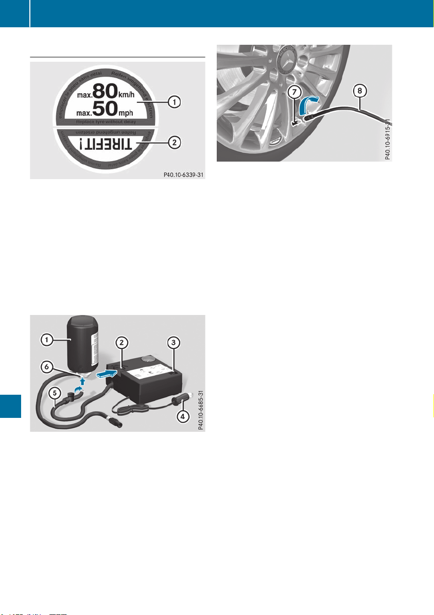
Using the TIREFIT kit
X
Do not remove any foreign objects which have
penetrated the tire, e.g. screws or nails.
X
Remove the tire sealant bottle, the accompa-
nying TIREFIT sticker and the tire inflation
compressor from the stowage well under-
neath the cargo compartment floor
(Y page 335).
X
Affix part : of the TIREFIT sticker to the
instrument cluster within the driver's field of
vision.
X
Affix part ; of the TIREFIT sticker near the
valve on the wheel with the defective tire.
X
Pull connector ? with the cable and hose A
out of the tire inflation compressor housing.
X
Screw hose A onto flange B of tire sealant
bottle :.
X
Place tire sealant bottle : head down into
recess ; of the tire inflation compressor.
X
Remove the cap from valve C on the faulty
tire.
X
Screw filler hose D onto valve C.
X
Insert connector ? into a socket in your vehi-
cle.
Cigarette lighter socket: (Y page 307)
12 V sockets: (Y page 308)
Observe the notes on the cigarette lighter
(Y page 307). Observe the notes on sockets
(Y page 308).
X
Turn the SmartKey to position 1 in the igni-
tion lock (Y page 135).
X
Press on and off switch = on the tire inflation
compressor to I.
The tire inflation compressor is switched on.
The tire is inflated.
First, tire sealant is pumped into the tire. The
pressure may briefly rise to approximately
500 kPa (5 bar/73 psi).
Do not switch off the tire inflation com-
pressor during this phase.
X
Let the tire inflation compressor run for a
maximum of five minutes. The tire should then
have attained a pressure of at least 180 kPa
(1.8 bar/26 psi).
If a pressure of 180 kPa (1.8 bar/26 psi) has
been attained after five minutes, see "Tire pres-
sure reached" (Y page 339).
If a tire pressure of 180 kPa (1.8 bar/26 psi) has
not been attained after five minutes, see "Tire
pressure not reached" (Y page 339).
If tire sealant has escaped, clean it off affected
areas as quickly as possible. It is preferable to
use clean water.
If your clothes are soiled with tire sealant, have
them cleaned with perchloroethylene at a dry
cleaner as soon as possible.
338
Flat tire
Breakdown assistance

Tire pressure not reached
If a pressure of 180 kPa (1.8 bar/26 psi) has not
been attained after five minutes:
X
Switch off the tire inflation compressor.
X
Unscrew the filler hose from the valve of the
faulty tire.
Note that tire sealant may escape when you
unscrew the filler hose.
X
Very slowly drive forwards or reverse approx-
imately 30 ft (10 m).
X
Pump up the tire again.
After a maximum of five minutes the tire pres-
sure must be at least 180 kPa (1.8 bar/
26 psi).
G
WARNING
If the required tire pressure is not reached
after the specified time, the tire is too badly
damaged. The tire sealant cannot repair the
tire in this instance. Damaged tires and a tire
pressure that is too low can significantly
impair the vehicle's braking and driving char-
acteristics. There is a risk of accident.
Do not continue driving. Contact a qualified
specialist workshop.
Tire pressure reached
G
WARNING
A tire temporarily sealed with tire sealant
impairs the driving characteristics and is not
suitable for higher speeds. There is a risk of
accident.
You should therefore adapt your driving style
accordingly and drive carefully. Do not exceed
the specified maximum speed with a tire that
has been repaired using tire sealant.
The maximum permissible speed for a tire
sealed with tire sealant is 50 mph (80 km/h).
The upper part of the TIREFIT sticker must be
affixed to the instrument cluster in the driver's
field of vision.
!
Residue from the tire sealant may come out
of the filler hose after use. This could cause
stains.
Therefore, place the filler hose in the plastic
bag which contained the TIREFIT kit.
H
Environmental note
Have the used tire sealant bottle disposed of
professionally, e.g. at a qualified specialist
workshop.
If a tire pressure of 180 kPa (1.8 bar/26 psi) has
been attained after five minutes:
X
Switch off the tire inflation compressor.
X
Unscrew the filler hose from the valve of the
faulty tire.
X
Stow the tire sealant bottle and the tire infla-
tion compressor.
X
Pull away immediately.
X
Stop after driving for approximately ten
minutes and check the tire pressure with the
tire inflation compressor.
The tire pressure must now be at least
130 kPa (1.3 bar/19 psi).
G
WARNING
If the required tire pressure is not reached
after driving for a short period, the tire is too
badly damaged. The tire sealant cannot repair
the tire in this instance. Damaged tires and a
tire pressure that is too low can significantly
impair the vehicle's braking and driving char-
acteristics. There is a risk of accident.
Do not continue driving. Contact a qualified
specialist workshop.
i
In cases such as the one mentioned above,
contact an authorized Mercedes-Benz Cen-
ter. Or call 1-800 FOR-MERCEDES (in the
USA) or 1-800-387-0100 (in Canada).
X
Correct the tire pressure if it is still at least
130 kPa (1.3 bar/19 psi). See the Tire and
Loading Information placard on the driver's
side B-pillar or the tire pressure table in the
fuel filler flap for values.
X
To increase the tire pressure: switch on the
tire inflation compressor.
Flat tire
339
Breakdown assistance
Z
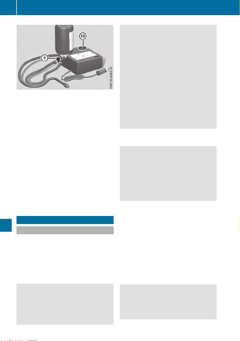
X
To reduce the tire pressure: press pressure
release button E on the filler hose.
X
The tire pressure is shown on pressure gauge
F.
X
When the tire pressure is correct, unscrew the
filler hose from the valve of the sealed tire.
X
Screw the valve cap onto the tire valve of the
sealed tire.
X
Pull the tire sealant bottle out of the tire infla-
tion compressor.
The filler hose remains attached to the tire
sealant bottle.
X
Drive to the nearest qualified specialist work-
shop and have the tire changed there.
X
Have the tire sealant bottle replaced as soon
as possible at a qualified specialist workshop.
X
Have the tire sealant bottle replaced every
four years at a qualified specialist workshop.
Battery (vehicle)
12 V battery - important safety notes
Plug-in hybrid: be sure to read the separate
operating instructions. You could otherwise fail
to recognize dangers, e.g. due to high voltage.
Special tools and expert knowledge are required
when working on the battery, e.g. removal and
installation. You should therefore have all work
involving the battery carried out at a qualified
specialist workshop.
G
WARNING
Work carried out incorrectly on the battery
can lead, for example, to a short circuit and
thus damage the vehicle electronics. This can
lead to function restrictions applying to
safety-relevant systems, e.g. the lighting sys-
tem, the ABS (anti-lock braking system) or the
ESP
®
(Electronic Stability Program). The oper-
ating safety of your vehicle may be restricted.
You could lose control of the vehicle, for
example:
R
when braking
R
in the event of abrupt steering maneuvers
and/or when the vehicle's speed is not
adapted to the road conditions
There is a risk of an accident.
In the event of a short circuit or a similar inci-
dent, contact a qualified specialist workshop
immediately. Do not drive any further. You
should have all work involving the battery car-
ried out at a qualified specialist workshop.
For further information about ABS and ESP
®
,
see (Y page 66) and (Y page 70).
G
WARNING
Electrostatic build-up can lead to the creation
of sparks, which could ignite the highly explo-
sive gases of a battery. There is a risk of an
explosion.
Before handling the battery, touch the vehicle
body to remove any existing electrostatic
build-up.
The highly flammable gas mixture forms when
charging the battery as well as when jump-start-
ing.
Always make sure that neither you nor the bat-
tery is electrostatically charged. A build-up of
electrostatic charge can be caused, for exam-
ple:
R
by wearing clothing made from synthetic
fibers
R
due to friction between clothing and seats
R
if you push or pull the battery across the car-
pet or other synthetic materials
R
if you rub the battery with a cloth
G
WARNING
During the charging process, a battery produ-
ces hydrogen gas. If a short circuit occurs or
sparks are created, the hydrogen gas can
ignite. There is a risk of an explosion.
340
Battery (vehicle)
Breakdown assistance
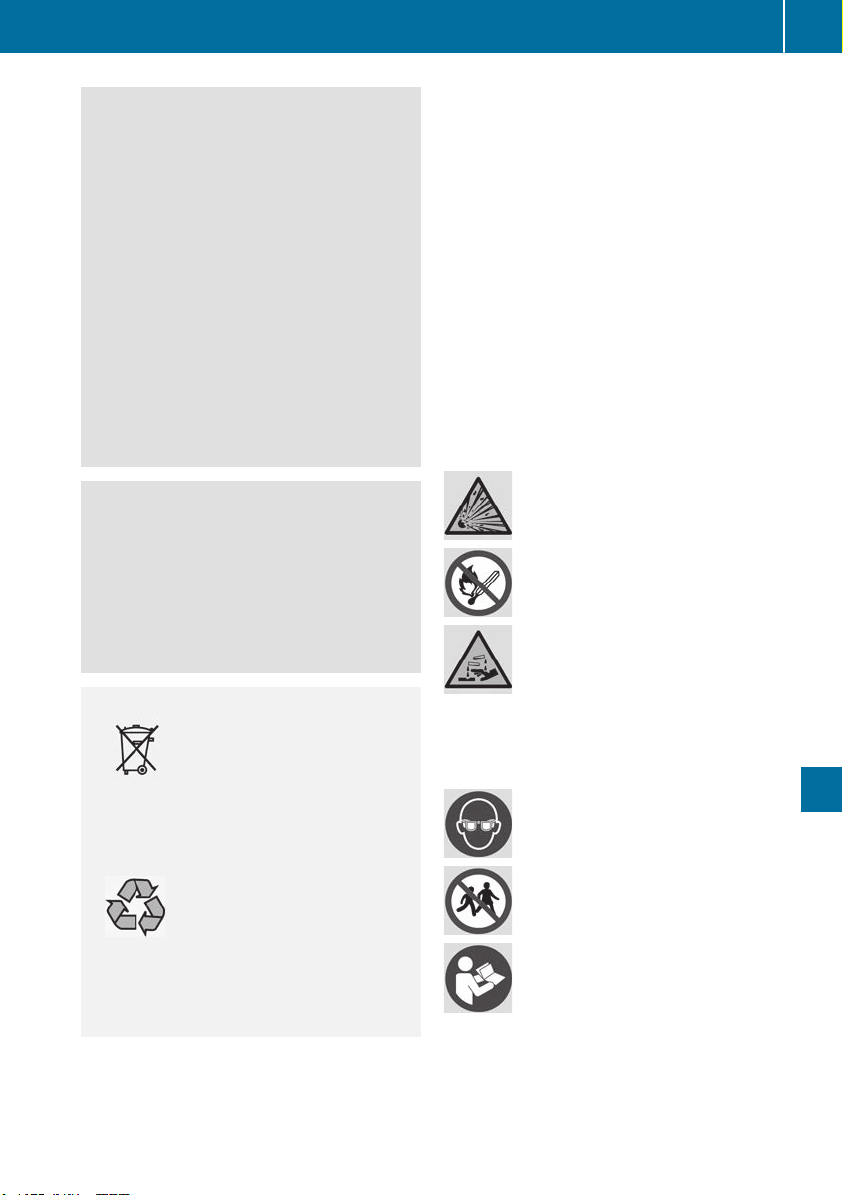
R
Make sure that the positive terminal of a
connected battery does not come into con-
tact with vehicle parts.
R
Never place metal objects or tools on a bat-
tery.
R
It is important that you observe the descri-
bed order of the battery terminals when
connecting and disconnecting a battery.
R
When jump-starting, make sure that the
battery poles with identical polarity are
connected.
R
It is particularly important to observe the
described order when connecting and dis-
connecting the jumper cables.
R
Never connect or disconnect the battery
terminals while the engine is running.
G
WARNING
Battery acid is caustic. There is a risk of injury.
Avoid contact with skin, eyes or clothing. Do
not inhale any battery gases. Do not lean over
the battery. Keep children away from batter-
ies. Wash away battery acid immediately with
plenty of clean water and seek medical atten-
tion.
H
Environmental note
Batteries contain dangerous
substances. It is against the
law to dispose of them with
the household rubbish. They
must be collected separately
and recycled to protect the
environment.
Dispose of batteries in an
environmentally friendly
manner. Take discharged
batteries to a qualified spe-
cialist workshop or a special
collection point for used bat-
teries.
!
Have the battery regularly checked at a
qualified specialist workshop.
For more information, please contact a quali-
fied specialist workshop.
!
Always have work on batteries carried out at
a qualified specialist workshop.
Should it, in exceptional circumstances, be
absolutely necessary to disconnect the 12-
volt battery yourself, please observe the fol-
lowing:
R
Secure the vehicle to prevent it from rolling
away.
R
Switch off the ignition.
R
Disconnect the negative terminal first and
then the positive terminal.
The transmission is locked in position j
after disconnecting the battery.
After the work has been done, install the bat-
tery and replace the cover of the positive ter-
minal clamp firmly.
Comply with safety precautions and take pro-
tective measures when handling batteries.
Risk of explosion.
Fire, open flames and smoking are
prohibited when handling the bat-
tery. Avoid creating sparks.
Battery acid is caustic. Avoid contact
with skin, eyes or clothing.
Wear suitable protective clothing,
especially gloves, apron and face-
guard.
Rinse any acid spills immediately
with clear water. Contact a physician
if necessary.
Wear eye protection.
Keep children away.
Observe this Operator's Manual.
For safety reasons, Mercedes-Benz recom-
mends that you only use batteries which have
been tested and approved for your vehicle by
Mercedes-Benz. These batteries provide
increased impact protection to prevent vehicle
Battery (vehicle)
341
Breakdown assistance
Z

occupants from suffering acid burns should the
battery be damaged in the event of an accident.
In order for the battery to achieve the maximum
possible service life, it must always be suffi-
ciently charged.
Like other batteries, the vehicle battery may
discharge over time if you do not use the vehicle.
In this case, have the battery disconnected at a
qualified specialist workshop. However, you can
also charge the battery with a charger recom-
mended by Mercedes-Benz. Contact a qualified
specialist workshop for further information.
Have the battery charge state checked more
frequently if you use the vehicle mainly for short
trips or if you leave it standing idle for a lengthy
period. Consult a qualified specialist workshop
if you wish to leave your vehicle parked for a long
period of time.
Remove the SmartKey if you park the vehicle
and do not require any electrical consumers.
The vehicle will then use very little energy, thus
conserving battery power.
If the power supply has been interrupted, e.g. if
you reconnect the battery, you will have to:
R
set the clock (see the Digital Operator's Man-
ual)
On vehicles with a multimedia system and
navigation system, the clock is set automati-
cally.
R
reset the function for automatically folding
the exterior mirrors in/out by folding the mir-
rors out once(Y page 106)
Charging the 12 V battery
G
WARNING
During charging and jump-starting, explosive
gases can escape from the battery. There is a
risk of an explosion.
Particularly avoid fire, open flames, creating
sparks and smoking. Ensure there is sufficient
ventilation while charging and jump-starting.
Do not lean over a battery.
G
WARNING
Battery acid is caustic. There is a risk of injury.
Avoid contact with skin, eyes or clothing. Do
not inhale any battery gases. Do not lean over
the battery. Keep children away from batter-
ies. Wash away battery acid immediately with
plenty of clean water and seek medical atten-
tion.
G
WARNING
A discharged battery can freeze at tempera-
tures below freezing point. When jump-start-
ing the vehicle or charging the battery, gases
can escape from the battery. There is a risk of
an explosion.
Allow the frozen battery to thaw out before
charging it or jump-starting.
!
Only use battery chargers with a maximum
charging voltage of 14.8 V.
!
Only charge the battery using the jump-
starting connection point.
The jump-starting connection point is in the
engine compartment (Y page 343).
X
Open the hood.
X
Connect the battery charger to the positive
terminal and ground point in the same order
as when connecting the donor battery in the
jump-starting procedure (Y page 343).
Keep away from fire and open flames. Do not
lean over a battery. Never charge the battery if it
is still installed in the vehicle, unless you use a
battery charger which has been tested and
approved by Mercedes-Benz. A battery charger
unit specially adapted for Mercedes-Benz vehi-
cles and tested and approved by Mercedes-
Benz is available as an accessory. It permits the
charging of the battery in its installed position.
Contact an authorized Mercedes-Benz Center
for further information and availability. Read the
battery charger's operating instructions before
charging the battery.
If, at low temperatures, the indicator lamps/
warning lamps in the instrument cluster do not
light up, it is highly likely that the discharged
battery has frozen. In this case you may neither
jump-start the vehicle nor charge the battery.
The service life of a thawed-out battery may be
shorter. The starting characteristics can be
impaired, particularly at low temperatures. Have
the thawed-out battery checked at a qualified
specialist workshop.
342
Battery (vehicle)
Breakdown assistance

Replacing the 12 V battery
Observe the notes on the 12 V battery.
Mercedes-Benz recommends that you have the
12 V battery replaced at a qualified specialist
workshop, e.g. at an authorized Mercedes-Benz
Center.
If you want to replace the battery yourself,
observe the following notes:
R
Always replace a defective battery with a bat-
tery which meets the specific requirements of
the vehicle.
The vehicle is equipped with an AGM (Absorb-
ent Glass Mat) technology battery. Full vehi-
cle functionality is only guaranteed with an
AGM battery. For safety reasons, Mercedes-
Benz recommends that you only use batteries
which have been tested and approved for your
vehicle by Mercedes-Benz.
R
Use detachable parts such as breather hoses,
angled connecting pieces or terminal covers
from the battery which is to be replaced.
R
Make sure that the vent hose is always con-
nected to the original opening on the battery
side.
Install any existing or supplied stop plugs.
Otherwise, gases or battery acid could
escape.
R
Make sure that the detachable parts are con-
nected again in the same way.
Jump-starting
Plug-in hybrid: be sure to read the separate Operator's Manual. You could otherwise fail to rec-
ognize dangers, e.g. due to high voltage.
For the jump-starting procedure, use only the jump-starting connection point in the engine com-
partment, consisting of a positive terminal and a ground point.
G
WARNING
Battery acid is caustic. There is a risk of injury.
Avoid contact with skin, eyes or clothing. Do not inhale any battery gases. Do not lean over the
battery. Keep children away from batteries. Wash away battery acid immediately with plenty of
clean water and seek medical attention.
G
WARNING
During charging and jump-starting, explosive gases can escape from the battery. There is a risk
of an explosion.
Particularly avoid fire, open flames, creating sparks and smoking. Ensure there is sufficient ven-
tilation while charging and jump-starting. Do not lean over a battery.
G
WARNING
During the charging process, a battery produces hydrogen gas. If a short circuit occurs or sparks
are created, the hydrogen gas can ignite. There is a risk of an explosion.
R
Make sure that the positive terminal of a connected battery does not come into contact with
vehicle parts.
R
Never place metal objects or tools on a battery.
R
It is important that you observe the described order of the battery terminals when connecting
and disconnecting a battery.
R
When jump-starting, make sure that the battery poles with identical polarity are connected.
R
It is particularly important to observe the described order when connecting and disconnecting
the jumper cables.
R
Never connect or disconnect the battery terminals while the engine is running.
Jump-starting
343
Breakdown assistance
Z

G
WARNING
A discharged battery can freeze at temperatures below freezing point. When jump-starting the
vehicle or charging the battery, gases can escape from the battery. There is a risk of an explosion.
Allow the frozen battery to thaw out before charging it or jump-starting.
!
Vehicles with a gasoline engine: avoid repeated and lengthy starting attempts. Otherwise, the
catalytic converter could be damaged by non-combusted fuel.
If the indicator/warning lamps do not light up at low temperatures, it is very likely that the dis-
charged battery has frozen. In this case you may neither jump-start the vehicle nor charge the
battery. The service life of a thawed-out battery may be shorter. The starting characteristics can be
impaired, particularly at low temperatures. Have the thawed-out battery checked at a qualified
specialist workshop.
Do not start the vehicle using a rapid charging device. If your vehicle's battery is discharged, the
engine can be jump-started from another vehicle or from a donor battery using jumper cables.
Observe the following points:
R
The battery is not accessible in all vehicles. If the other vehicle's battery is not accessible, jump-
start the vehicle using a donor battery or a jump-starting device.
R
Vehicles with a gasoline engine: only jump-start the vehicle when the engine and exhaust
system are cold.
R
Do not start the engine if the battery is frozen. Let the battery thaw first.
R
Only jump-start from batteries with a 12 V voltage rating.
R
Only use jumper cables which have a sufficient cross-section and insulated terminal clamps.
R
If the battery is fully discharged, leave the battery that is being used to jump-start connected for
a few minutes before attempting to start. This charges the battery slightly.
R
Make sure that the two vehicles do not touch.
Make sure that:
R
The jumper cables are not damaged.
R
Bare parts of the terminal clamp do not come into contact with other metal parts while the jumper
cables are connected to the battery.
R
The jumper cables cannot come into contact with parts that can move when the engine is running,
such as the V-belt pulley or the fan.
X
Secure the vehicle by applying the electric parking brake.
X
Shift the transmission to position j.
X
Make sure that the ignition is switched off. All indicator lamps in the instrument cluster must be
off. When using the SmartKey, turn the SmartKey to position u in the ignition lock and remove it
(Y page 135).
X
Switch off all electrical consumers, e.g. rear window defroster, lighting, etc.
X
Open the hood.
i
Right-hand-drive vehicle: the jump-starting connection points may be located on the other
side of the vehicle.
344
Jump-starting
Breakdown assistance
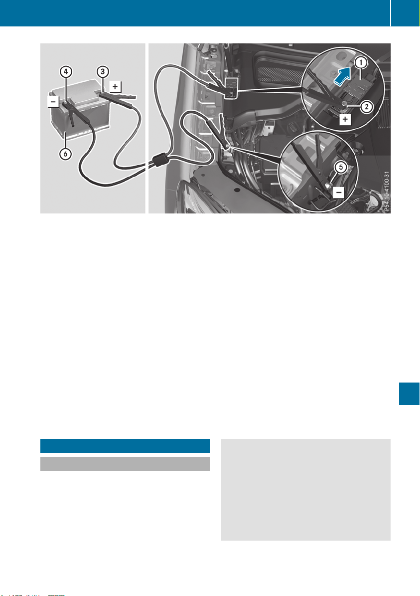
Position number B identifies the charged battery of the other vehicle or an equivalent jump-starting
device.
X
Slide cover : of positive terminal ; in the direction of the arrow.
X
Connect positive terminal ; on your vehicle to positive terminal = of donor battery B using the
jumper cable, always begin with positive terminal ; on your own vehicle first.
X
Start the engine of the donor vehicle and run it at idling speed.
X
Connect negative terminal ? of donor battery B to ground point A of your vehicle using the
jumper cable, beginning with donor battery B first.
X
Start the engine.
X
Before disconnecting the jumper cables, let the engine run for several minutes.
X
First, remove the jumper cables from ground point A and negative terminal ?, then from pos-
itive terminal ; and positive terminal =. Begin each time at the contacts on your own vehicle
first.
X
Close cover : of positive terminal ; after removing the jumper cables.
X
Have the battery checked at a qualified specialist workshop.
Jump-starting is not considered to be a normal operating condition.
i
Jumper cables and further information regarding jump-starting can be obtained at any qualified
specialist workshop.
Towing and tow-starting
Important safety notes
Plug-in hybrid: be sure to read the separate
Operator's Manual. You could otherwise fail to
recognize dangers, e.g. due to high voltage.
G
WARNING
Functions relevant to safety are restricted or
no longer available if:
R
the engine is not running.
R
the brake system or the power steering is
malfunctioning.
R
there is a malfunction in the voltage supply
or the vehicle's electrical system.
Towing and tow-starting
345
Breakdown assistance
Z

If your vehicle is being towed, much more
force may be necessary to steer or brake.
There is a risk of an accident.
In such cases, use a tow bar. Before towing,
make sure that the steering moves freely.
G
WARNING
When towing or tow-starting another vehicle
and its weight is greater than the permissible
gross weight of your vehicle, the:
R
the towing eye could detach itself
R
the vehicle/trailer combination could roll-
over.
There is a risk of an accident.
When towing or tow-starting another vehicle,
its weight should not be greater than the per-
missible gross weight of your vehicle.
Details on the permissible gross vehicle weight
of your vehicle can be found on the vehicle iden-
tification plate (Y page 382).
!
When Active Brake Assist, Active Distance
Assist DISTRONIC or the HOLD function is
activated, the vehicle brakes automatically in
certain situations.
To avoid damage to the vehicle, deactivate
these systems in the following or similar sit-
uations:
R
when towing the vehicle
R
in the car wash
!
Make sure that the electric parking brake is
released. If the electric parking brake is faulty,
visit a qualified specialist workshop.
!
Only secure the tow rope or tow bar at the
towing eyes, or the trailer tow hitch, if availa-
ble. You could otherwise damage the vehicle.
!
Observe the following points when towing
with a tow rope:
R
Secure the tow rope on the same side on
both vehicles.
R
Make sure that the tow rope is not longer
than legally permitted. Mark the tow rope in
the middle, e.g. with a white cloth
(11.8 x 11.8 in). This will make other road
users aware that a vehicle is being towed.
R
Only secure the tow cable to the towing
eyes or, if available, to the trailer tow hitch.
R
Observe the brake lamps of the towing
vehicle while driving. Always maintain a dis-
tance a distance so that the tow rope does
not sag.
R
Do not use steel cables or chains to tow
your vehicle. You could otherwise damage
the vehicle.
!
Do not use the trailer tow hitch for recovery
or towing. Do not use the towing eye for
recovery. this could damage the vehicle. If in
doubt, have the vehicle recovered using a
crane.
!
When towing, pull away slowly and
smoothly. Pull the towed vehicle as straight as
possible and not at an acute angle. Excessive
tractive power could damage the vehicles.
When towing, it is preferable to use a rigid tow-
ing bar as opposed to a tow rope. A rigid towing
bar helps to keep the tractive power low.
!
When towing away vehicles with KEYLESS-
GO, use the key instead of the Start/Stop
button. The automatic transmission may oth-
erwise shift to position j when you open the
driver's or front-passenger door, which could
damage the transmission.
!
Do not tow with sling-type equipment. This
could damage the vehicle.
!
Vehicles with differential locks: make sure
the differential locks are in automatic mode.
When towing, the differential locks must not
be switched on. The transmission may other-
wise be damaged.
!
You may tow the vehicle for a maximum dis-
tance of 30 miles (50 kilometers). A towing
speed of 30 mph (50 km/h) must not be
exceeded.
For towing distances over 30 miles
(50 kilometers), the entire vehicle must be
raised and transported.
It is better to have the vehicle transported than
to have it towed away.
If the vehicle has suffered transmission damage,
have it transported on a transporter or trailer.
The automatic transmission must be in position
i when the vehicle is being towed.
346
Towing and tow-starting
Breakdown assistance
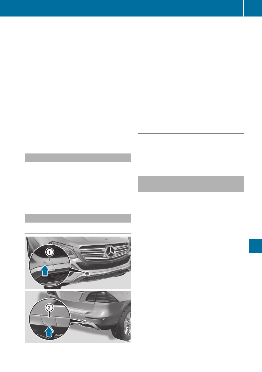
The battery must be connected and charged.
Otherwise, you:
R
cannot turn the SmartKey to position 2 in
the ignition lock
R
cannot release the electric parking brake.
R
cannot shift the automatic transmission to
position i
Disarm the automatic locking feature before the
vehicle is towed (Y page 240). You could other-
wise be locked out when pushing or towing the
vehicle.
If the vehicle is in a dangerous area, it can be
towed out of that area with both axles on the
ground. In this case, the towing distance must
not be greater than 165 ft (50 m) and must not
exceed a towing speed of 6 mph (10 km/h). For
longer distances, have the vehicle loaded and
transported.
Permitted towing methods
Mercedes-Benz recommends transporting your
vehicle in the case of a breakdown, rather than
towing it away.
When towing away, use a towing rope or a tow-
ing bar with both axles on the ground. Do not use
any tow bar systems.
Installing/removing the towing eye
Installing the towing eye
The brackets for the screw-in towing eye are
located in the bumpers. They are at the front and
rear behind covers :;.
X
Remove the towing eye from the vehicle tool
kit (Y page 335).
X
To open the cover at the front: press the
mark on cover : inwards in the direction of
the arrow.
X
To open the cover at the rear: insert a flat,
blunt object into the cutout and lever
cover ; out of the bumper.
X
Take cover : or ; off the opening.
X
Screw in the towing eye clockwise as far as it
will go and tighten it.
Removing the towing eye
X
Unscrew and remove the towing eye.
X
Position cover : or ; in the bumper and
press the cover on until it engages.
X
Place the towing eye in the vehicle tool kit.
Towing a vehicle with both axles on
the ground
The automatic transmission shifts to position
j automatically when you open the driver's or
front-passenger door or when you remove the
SmartKey from the ignition lock.
In order to ensure that the automatic transmis-
sion stays in position i when towing away the
vehicle, you must observe the following points:
X
Make sure that the vehicle is stationary.
X
Turn the SmartKey to position 2 in the igni-
tion lock.
X
Depress and hold the brake pedal.
X
Shift the automatic transmission to position
i.
X
Leave the SmartKey in position 2 in the igni-
tion lock.
X
Release the brake pedal.
X
Release the electric parking brake.
X
Switch on the hazard warning lamps
(Y page 112).
In order to signal a change of direction when
towing the vehicle with the hazard warning
lamps switched on, use the combination switch
as usual. In this case, only the indicator lamps
for the direction of travel flash. After resetting
Towing and tow-starting
347
Breakdown assistance
Z
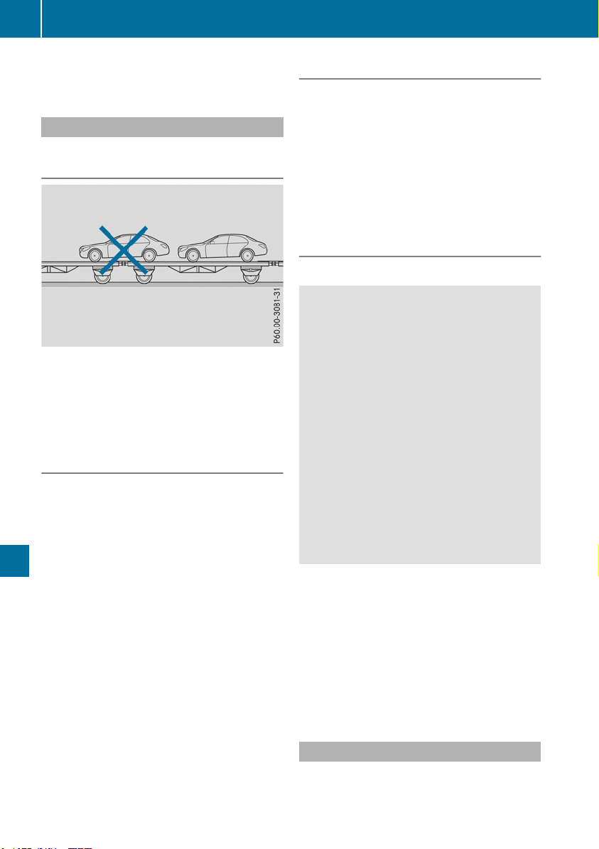
the combination switch, the hazard warning
lamp starts flashing again.
Transporting the vehicle
4MATIC vehicles/vehicles with auto-
matic transmission
!
When the vehicle is loaded for transport, the
front and rear axles must be stationary and on
the same transportation vehicle. Positioning
over the connection point of the transport
vehicle is not permitted. The drive train may
otherwise be damaged.
All vehicles
!
You may only secure the vehicle by the
wheels, not by parts of the vehicle such as
axle or steering components. Otherwise, the
vehicle could be damaged.
The towing eye can be used to pull the vehicle
onto a trailer or transporter for transporting pur-
poses.
X
Turn the SmartKey to position 2 in the igni-
tion lock.
X
Shift the automatic transmission to position
i.
As soon as the vehicle has been loaded:
X
Prevent the vehicle from rolling away by
applying the electric parking brake.
X
Shift the automatic transmission to position
j.
X
Turn the SmartKey to position u in the igni-
tion lock and remove it.
X
Secure the vehicle.
Securing the vehicle
!
After loading, the vehicle must be secured at
all four wheels. Otherwise, the vehicle could
be damaged.
A minimum distance of 8 in (20 cm) up and
4 in (10 cm) down must be maintained to the
transport platform.
X
Secure all four wheels after loading the vehi-
cle.
Vehicles with ADS PLUS (Adaptive
Damping System PLUS)
Important safety notes
G
WARNING
The weaker damping forces of the vehicle to
be transported can cause the vehicle/trailer
combination to swing.
As a result, when transporting vehicles with
Adaptive Damping System PLUS, the vehicle/
trailer combination may start to skid. Conse-
quently, you could lose control of the vehicle.
There is a risk of accident and injury.
When transporting, make sure that:
R
the vehicle is has been loaded onto the
transporter correctly
R
the vehicle is secured at all four wheels with
suitable tensioning straps
R
you do not exceed the maximum permissi-
ble speed of 35 mph (60 km/h)
Securing the vehicle
!
After loading, the vehicle must be secured at
all four wheels. Otherwise, the vehicle could
be damaged.
A minimum distance of 8 in (20 cm) up and
4 in (10 cm) down must be maintained to the
transport platform.
X
Secure all four wheels after loading the vehi-
cle.
Information on 4MATIC vehicles
!
Vehicles with 4MATIC must not be towed
with either the front or the rear axle raised, as
doing so will damage the transmission.
348
Towing and tow-starting
Breakdown assistance

Vehicles with 4MATIC may either be towed away
with both axles on the ground or be loaded up
and transported.
If the vehicle's transmission, front, or rear axle is
damaged, have the vehicle transported on a
truck or trailer.
In the event of damage to the electrical sys-
tem: if the battery is defective, the automatic
transmission will be locked in position j. To
shift the automatic transmission to position i,
you must provide power to the vehicle's on-
board electrical system in the same way as
when jump-starting (Y page 343).
Have the vehicle transported on a transporter or
trailer.
Tow-starting (emergency engine
starting)
!
Vehicles with automatic transmission must
not be tow-started. You could otherwise dam-
age the automatic transmission.
You can find information on "Jump-starting"
under (Y page 343).
Fuses
Important safety notes
G
WARNING
If you manipulate or bridge a faulty fuse or if
you replace it with a fuse with a higher amper-
age, the electric cables could be overloaded.
This could result in a fire. There is a risk of an
accident and injury.
Always replace faulty fuses with the specified
new fuses having the correct amperage.
!
For the fuse boxes in the engine compart-
ment and under the rear bench seat, only use
fuses with the suffix "S". Otherwise, compo-
nents or systems could be damaged.
!
Make sure that no moisture can enter the
fuse box when the cover is open.
!
When closing the cover, make sure that it is
lying correctly on the fuse box. Moisture seep-
ing in or dirt could otherwise impair the oper-
ation of the fuses.
The fuses in your vehicle serve to close down
faulty circuits. If a fuse blows, all the compo-
nents on the circuit and their functions stop
operating.
Blown fuses must be replaced with fuses of the
same rating, which you can recognize by the
color and value. The fuse ratings are listed in the
fuse allocation chart.
The fuse allocation chart is located in the fuse
box under the rear bench seat (Y page 350).
If a newly inserted fuse also blows, have the
cause traced and rectified at a qualified special-
ist workshop, e.g. an authorized Mercedes-Benz
Center.
Before changing a fuse
Observe the important safety notes
(Y page 349)
X
Switch off the engine.
X
Switch off all electrical consumers.
X
Remove the SmartKey from the ignition lock.
Or, on vehicles with KEYLESS-GO start function
or KEYLESS‑GO:
X
Open the driver's door.
The vehicle electronics are now in key posi-
tion u. This is the same as the SmartKey
having been removed.
The driver’s door can be closed again.
X
Secure the vehicle against rolling away
(Y page 156).
All indicator lamps in the instrument cluster
must be off.
The fuses are located in various fuse boxes:
R
Fuse box on the front-passenger side of the
dashboard
R
Fuse box in the engine compartment on the
right-hand side of the vehicle, when viewed in
the direction of travel
R
Fuse box under the rear bench seat
Dashboard fuse box
!
Do not use a pointed object such as a screw-
driver to open the cover in the dashboard. You
could damage the dashboard or the cover.
Mercedes-Benz recommends that you have this
work performed at a qualified specialist work-
Fuses
349
Breakdown assistance
Z
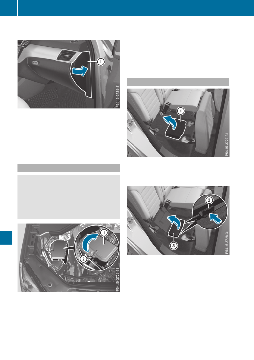
shop, e.g. at an authorized Mercedes-Benz Cen-
ter.
X
Open the front-passenger door.
X
To open: pull cover : outwards in the direc-
tion of the arrow and remove it.
X
To close: clip in cover : on the front of the
dashboard.
X
Fold cover : inwards until it engages.
Fuse box in the engine compartment
G
WARNING
When the hood is open and the windshield
wipers are set in motion, you can be injured by
the wiper linkage. There is a risk of injury.
Always switch off the windshield wipers and
the ignition before opening the hood.
X
Open the hood (Y page 321).
X
Use a dry cloth to remove any moisture from
the fuse box.
X
To open: open clamps ;.
X
Fold up cover : in the direction of the arrow
and remove it.
X
To close: check whether the seal is seated
correctly in cover :.
X
Insert cover : at the side of the fuse box into
the retainers.
X
Fold down cover : and close clamps ;.
X
Close the hood.
Fuse box under the rear bench seat
X
Fold the right-hand rear bench seat forward
(Y page 298).
X
To open: lift and fold out carpet : in the
direction of the arrow.
X
Release clamps ; by pressing them in the
direction of the arrow.
X
Fold cover = up in the direction of the arrow
and remove it.
i
The fuse allocation chart is located under
cover =.
X
To close: insert cover = into the retainers on
the side of the fuse box.
X
Fold down cover = until clamps ; engage
audibly.
X
Fold the right-hand rear bench seat back
(Y page 298).
350
Fuses
Breakdown assistance

Important safety notes
G
WARNING
If wheels and tires of the wrong size are used,
the wheel brakes or suspension components
may be damaged. There is a risk of an acci-
dent.
Always replace wheels and tires with those
that fulfill the specifications of the original
part.
When replacing wheels, make sure to use the
correct:
R
designation
R
model
When replacing tires, make sure to use the
correct:
R
designation
R
manufacturer
R
model
G
WARNING
A flat tire severely impairs the driving, steer-
ing and braking characteristics of the vehicle.
There is a risk of accident.
Tires without run-flat characteristics:
R
do not drive with a flat tire.
R
immediately replace the flat tire with your
emergency spare wheel or spare wheel, or
consult a qualified specialist workshop.
Tires with run-flat characteristics:
R
pay attention to the information and warn-
ing notices on MOExtended tires (tires with
run-flat characteristics).
Accessories that are not approved for your vehi-
cle by Mercedes-Benz or are not being used cor-
rectly can impair the operating safety.
Before purchasing and using non-approved
accessories, visit a qualified specialist work-
shop and inquire about:
R
suitability
R
legal stipulations
R
factory recommendations
Further information regarding wheels and tires
can be found under "Wheel/tire combinations"
(Y page 376).
You can ask for information regarding permitted
wheel-tire combinations at an authorized
Mercedes-Benz Center.
Tire pressure information can be found:
R
on the Tire and Loading Information placard
on the B-pillar on the driver's side
R
in the tire pressure table in the fuel filler flap
R
in the "Tire pressure" section
Operation
Information on driving
Check the tire pressure when the vehicle is
heavily laden and adjust prior to a trip.
While driving, pay attention to vibrations, noises
and unusual handling characteristics, e.g. pull-
ing to one side. This may indicate that the
wheels or tires are damaged. If you suspect that
a tire is defective, reduce your speed immedi-
ately. Stop the vehicle as soon as possible to
check the wheels and tires for damage. Hidden
tire damage could also be causing the unusual
handling characteristics. If you find no signs of
damage, have the tires and wheels checked at a
qualified specialist workshop.
When parking your vehicle, make sure that the
tires do not get deformed by the curb or other
obstacles. If it is necessary to drive over curbs,
speed humps or similar elevations, try to do so
slowly and at an obtuse angle. Otherwise, the
tires, particularly the sidewalls, may be dam-
aged.
Regular checking of wheels and tires
G
WARNING
Damaged tires can cause tire inflation pres-
sure loss. As a result, you could lose control of
your vehicle. There is a risk of accident.
Check the tires regularly for signs of damage
and replace any damaged tires immediately.
Check wheels and tires for damage at least once
a month. Check wheels and tires after driving
off-road or on rough roads. Damaged wheels
can cause a loss of tire pressure.
Operation
351
Wheels and tires
Z
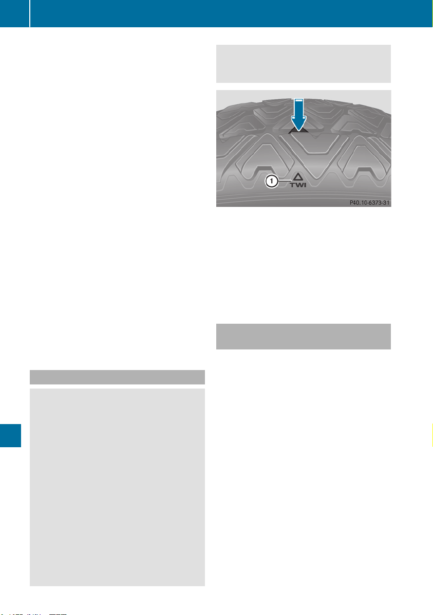
Pay particular attention to damage such as:
R
Cuts in the tires
R
Punctures in the tires
R
Tears in the tires
R
Bulges on tires
R
Deformation or severe corrosion on wheels
Regularly check the tire tread depth and the
condition of the tread across the whole width of
all tires (Y page 352). If necessary, turn the
front wheels to full lock in order to inspect the
inner side of the tire surface.
All wheels must have a valve cap to protect the
valve against dirt and moisture. Do not mount
anything onto the valve other than the standard
valve cap or other valve caps approved by
Mercedes-Benz for your vehicle. Do not use any
other valve caps or systems, e.g. tire pressure
monitoring systems.
Regularly check the pressure of all the tires par-
ticularly prior to long trips. Adjust the tire pres-
sure as necessary (Y page 354).
Observe the notes on the emergency spare
wheel (Y page 376).
The service life of tires depends, among other
things, on the following factors:
R
Driving style
R
Tire pressure
R
Distance covered
Notes on tire tread
G
WARNING
Insufficient tire tread will reduce tire traction.
The tire is no longer able to dissipate water.
This means that on wet road surfaces, the risk
of hydroplaning increases, in particular where
speed is not adapted to suit the driving con-
ditions. There is a risk of accident.
If the tire pressure is too high or too low, tires
may exhibit different levels of wear at differ-
ent locations on the tire tread. Thus, you
should regularly check the tread depth and
the condition of the tread across the entire
width of all tires.
Minimum tire tread depth for:
R
Summer tires: â in (3 mm)
R
M+S tires: ã in (4 mm)
For safety reasons, replace the tires before
the legally prescribed limit for the minimum
tire tread depth is reached.
Marking : shows where the bar indicator
(arrow) for tread wear is integrated into the tire
tread.
Treadwear indicators (TWI) are required by law.
Six indicators are positioned on the tire tread.
They are visible once a tread depth of approx-
imately á in (1.6 mm) has been reached. If this
is the case, the tire is so worn that it must be
replaced.
Selecting, mounting and replacing
tires
R
Only mount tires and wheels of the same type
and make.
Exception: it is permissible to mount a differ-
ent type or make in the event of a flat tire.
Observe here the "MOExtended tires (tires
with run-flat characteristics)" section
(Y page 336).
R
Only mount tires of the correct size onto the
wheels.
R
Break in new tires at moderate speeds for the
first 60 miles (100 km). The new tires only
reach their full performance after this dis-
tance.
R
Do not drive with tires which have too little
tread depth. This significantly reduces the
traction on wet roads (hydroplaning).
R
Replace the tires after six years at the latest,
regardless of wear.
Observe the notes on the emergency spare
wheel (Y page 376).
352
Operation
Wheels and tires

MOExtended tires (tires with run-flat
properties)
With MOExtended tires (tires with run flat char-
acteristics), you can continue to drive your vehi-
cle even if there is a total loss of pressure in one
or more tires.
MOExtended tires may only be used in conjunc-
tion with an active tire pressure loss warning
system or with an active tire pressure monitor
and on wheels specifically tested by Mercedes-
Benz.
Notes on driving with MOExtended tires with a
flat tire (Y page 336).
i
Vehicles equipped with MOExtended tires
are not equipped with a TIREFIT kit at the fac-
tory. It is therefore recommended that you
additionally equip your vehicle with a TIREFIT
kit if you mount tires that do not feature run-
flat properties, e.g. winter tires. A TIREFIT kit
may be obtained from a qualified specialist
workshop.
Winter operation
General notes
Have your vehicle winter-proofed at a qualified
specialist workshop at the onset of winter.
Observe the notes in the "Changing a wheel"
section (Y page 371).
Driving with summer tires
At temperatures below 45 ‡ (+7 †), the elas-
ticity of summer tires and therefore also the
traction and braking capability are reduced con-
siderably. Change the tires on your vehicle to
M+S tires. Using summer tires at very cold tem-
peratures could cause cracks to form, thereby
damaging the tires permanently. Mercedes-
Benz cannot accept responsibility for this type
of damage.
G
WARNING
Damaged tires can cause tire inflation pres-
sure loss. As a result, you could lose control of
your vehicle. There is a risk of accident.
Check the tires regularly for signs of damage
and replace any damaged tires immediately.
M+S tires
G
WARNING
M+S tires with a tire tread depth of less than
ã in (4 mm) are not suitable for use in winter
and do not provide sufficient traction. There is
a risk of an accident.
M+S tires with a tread depth of less than ã in
(4 mm) must be replaced immediately.
At temperatures below 45 ‡(+7 †), use winter
tires or all-season tires. Both types of tire are
identified by the M+S marking.
Only winter tires bearing the i snowflake
symbol in addition to the M+S marking provide
the best possible grip in wintry road conditions.
Only these tires will allow driving safety systems
such as ABS and ESP
®
to function optimally in
winter. These tires have been developed specif-
ically for driving in snow.
Use M+S tires of the same make and tread on all
wheels to maintain safe handling characteris-
tics.
Always observe the maximum permissible
speed specified for the M+S tires you have
mounted.
Once the winter tires are mounted:
X
Check the tire pressures (Y page 357).
X
Restart the tire pressure monitor
(Y page 358).
X
Vehicles for Canada: restart the tire pres-
sure loss warning system (Y page 358).
Information about driving with an emergency
spare wheel (Y page 376).
Snow chains
G
WARNING
If snow chains are installed to the front
wheels, they may drag against the vehicle
body or chassis components. This could
cause damage to the vehicle or the tires.
There is a risk of an accident.
Winter operation
353
Wheels and tires
Z

To avoid hazardous situations:
R
never install snow chains to the front
wheels
R
always install snow chains in pairs to the
rear wheels.
!
Check the snow chains for damage before
mounting them. Damaged or worn snow
chains may snap and damage the following
components:
R
wheel
R
wheel housing
R
wheel suspension
For this reason, you must use only snow
chains that are free of defects. Observe the
manufacturer's mounting instructions.
!
You must drive at raised vehicle level (height
1) if snow chains have been installed. The
vehicle may otherwise be damaged.
!
Vehicles with ADS (Adaptive Damping
System): do not use the sport mode when
driving with snow chains mounted. The vehi-
cle may otherwise be damaged.
For safety reasons, Mercedes-Benz recom-
mends that you only use snow chains that have
been specially approved for your vehicle by
Mercedes-Benz, or are of a corresponding
standard of quality. For more information,
please contact a qualified specialist workshop.
Install the snow chains on all driven wheels for
maximum tractive power and driving stability. If
you own snow chains for two driven wheels only,
install the snow chains to the wheels on the rear
axle. The vehicle then remains more stable
under braking.
If you intend to mount snow chains, please bear
the following points in mind:
R
Snow chains may not be mounted on all
wheel/tire combinations. Permissible
wheel/tire combinations (Y page 376).
R
Only use snow chains when driving on roads
completely covered by snow. Remove the
snow chains as soon as possible when you
come to a road that is not snow-covered.
R
Local regulations may restrict the use of snow
chains. Observe the appropriate regulations if
you wish to mount snow chains.
R
Do not exceed the maximum permissible
speed of 30 mph (50 km/h).
R
When snow chains are installed, never use
Active Parking Assist (Y page 191) or the
Parking Package with rear view camera.
You may wish to deactivate ESP
®
(Y page 71)
when pulling away with snow chains mounted.
You can thereby allow the wheels to spin in a
controlled manner, achieving an increased driv-
ing force (cutting action).
Information about driving with an emergency
spare wheel (Y page 376).
Tire pressure
Tire pressure specifications
Important safety notes
G
WARNING
Underinflated or overinflated tires pose the
following risks:
R
the tires may burst, especially as the load
and vehicle speed increase.
R
the tires may wear excessively and/or
unevenly, which may greatly impair tire
traction.
R
the driving characteristics, as well as steer-
ing and braking, may be greatly impaired.
There is a risk of an accident.
Follow recommended tire inflation pressures
and check the pressure of all the tires includ-
ing the spare wheel:
R
monthly, at least
R
if the load changes
R
before beginning a long journey
R
under different operating conditions, e.g.
off-road driving
If necessary, correct the tire pressure.
Details on tire pressure can be found at the fol-
lowing positions in the vehicle:
R
Tire and Loading Information placard on the
B-pillar on the driver's side
R
Table for tire pressure on the inside of the fuel
filler flap
The tire pressure monitor does not warn you of:
354
Tire pressure
Wheels and tires
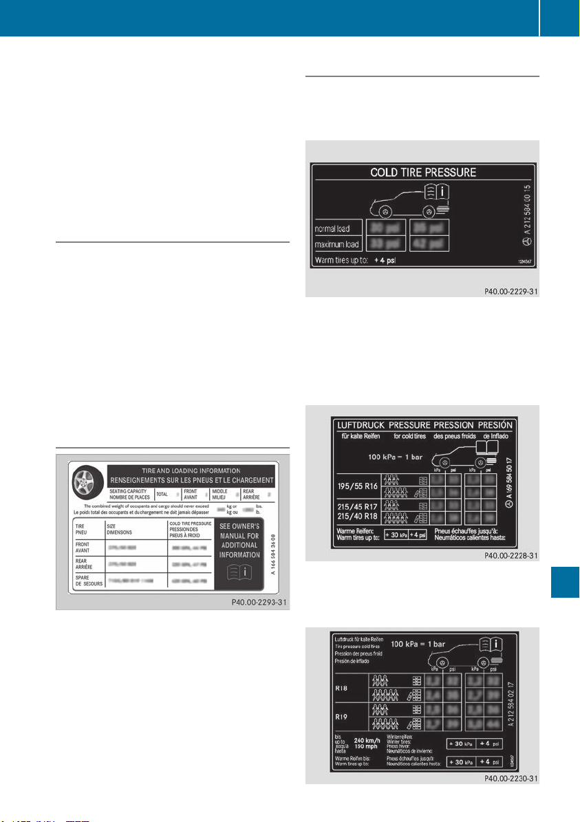
R
incorrectly set tire pressure
R
sudden loss of tire pressure, e.g. from a for-
eign object that has penetrated the tire
The data on the Tire and Loading Information
placard and tire pressure table shown here are
examples. Tire pressure specifications are vehi-
cle-specific and may deviate from the data
shown here. The tire pressure specifications
that are valid for your vehicle can be found on
the Tire and Loading Information placard and
tire pressure table on the vehicle.
General notes
The recommended tire pressures for the tires
mounted at the factory can be found on the
labels described here.
Operation with emergency spare wheel:
information on operation with the emergency
spare wheel can be found under "Emergency
spare wheel" (Y page 377).
Operation with a trailer: the applicable value
for the rear axle is the maximum tire pressure
value stated in the table inside the fuel filler flap.
Further information on tire pressures can be
obtained at a qualified specialist workshop.
Tire and Loading Information placard
Recommended tire pressures
The Tire and Loading Information placard is on
the B-pillar on the driver's side (Y page 361).
The Tire and Loading Information placard con-
tains the recommended tire pressures for cold
tires. The recommended tire pressures are valid
for the maximum permissible load and up to the
maximum permissible vehicle speed.
Tire pressure table
The tire pressure table is on the inside of the fuel
filler flap. It shows the tire pressure for all tires
permitted at the factory for this vehicle; see
illustration (example).
The tire pressure table contains the recommen-
ded pressures for cold tires for various operat-
ing conditions, i.e. differing load and speed con-
ditions.
If a tire size precedes a tire pressure, the fol-
lowing tire pressure information is only valid for
that tire size; see illustration (example).
The load conditions "partially laden" and "fully
laden" are defined in the table for different num-
bers of occupants and amounts of luggage. The
actual number of seats may differ.
Tire pressure
355
Wheels and tires
Z

Some tire pressure tables show only the rim
diameters instead of the full tire size, e.g. R18.
The rim diameter is part of the tire size and can
be found on the tire sidewall (Y page 366).
If the tire pressures have been set to the lower
values for lighter loads and/or lower road
speeds, the pressures should be reset to the
higher values:
R
if you want to drive with an increased load
and/or
R
if you want to drive at higher speeds
The tire pressures for increased loads and/or
higher road speeds, shown in the tire pressure
table, may have a negative effect on driving
comfort.
If the tire pressure is not set correctly, this can
lead to an excessive build up of heat and a sud-
den loss of pressure.
For more information, contact a qualified spe-
cialist workshop.
Important notes on tire pressure
G
WARNING
If the tire pressure drops repeatedly, the
wheel, valve or tire may be damaged. Tire
pressure that is too low may result in a tire
blow-out. There is a risk of an accident.
R
Check the tire for foreign objects.
R
Check whether the wheel is losing air or the
valve is leaking.
If you are unable to rectify the damage, con-
tact a qualified specialist workshop.
G
WARNING
If you fit unsuitable accessories onto tire
valves, the tire valves may be overloaded and
malfunction, which can cause tire pressure
loss. Due to their design, retrofitted tire pres-
sure monitors keep the tire valve open. This
can also result in tire pressure loss. There is a
risk of an accident.
Only screw the standard valve cap or other
valve caps approved by Mercedes-Benz for
your vehicle onto the tire valve.
Use a suitable pressure gauge to check the tire
pressure. The outer appearance of a tire does
not permit any reliable conclusion about the tire
pressure. On vehicles equipped with the elec-
tronic tire pressure monitor, the tire pressure
can be checked in the on-board computer.
The tire temperature and pressure increase
when the vehicle is in motion. This is dependent
on the driving speed and the load.
Therefore, you should only correct tire pres-
sures when the tires are cold.
The tires are cold:
R
if the vehicle has been parked with the tires
out of direct sunlight for at least three hours
and
R
if the vehicle has not been driven further than
1 mile (1.6 km)
The tire temperature changes depending on the
outside temperature, the vehicle speed and the
tire load. If the tire temperature changes by
18 ‡ (10 †), the tire pressure changes by
approximately 10 kPa (0.1 bar/1.5 psi). Take
this into account when checking the pressure of
warm tires. Only correct the tire pressure if it is
too low for the current operating conditions. If
you check the tire pressure when the tires are
warm, the resulting value will be higher than if
the tires were cold. This is normal. Do not
reduce the tire pressure to the value specified
for cold tires. The tire pressure would otherwise
be too low.
Observe the recommended tire pressures for
cold tires:
R
on the Tire and Loading Information placard
on the B-pillar on the driver's side
R
in the tire pressure table in the fuel filler flap
(Y page 152)
R
printed in yellow on the rim of the emer-
gency/collapsible spare wheel (depending on
vehicle equipment)
Underinflated or overinflated tires
Underinflated tires
G
WARNING
Tires with pressure that is too low can over-
heat and burst as a consequence. In addition,
they also suffer from excessive and/or irreg-
ular wear, which can severely impair the brak-
ing properties and the driving characteristics.
There is a risk of an accident.
356
Tire pressure
Wheels and tires
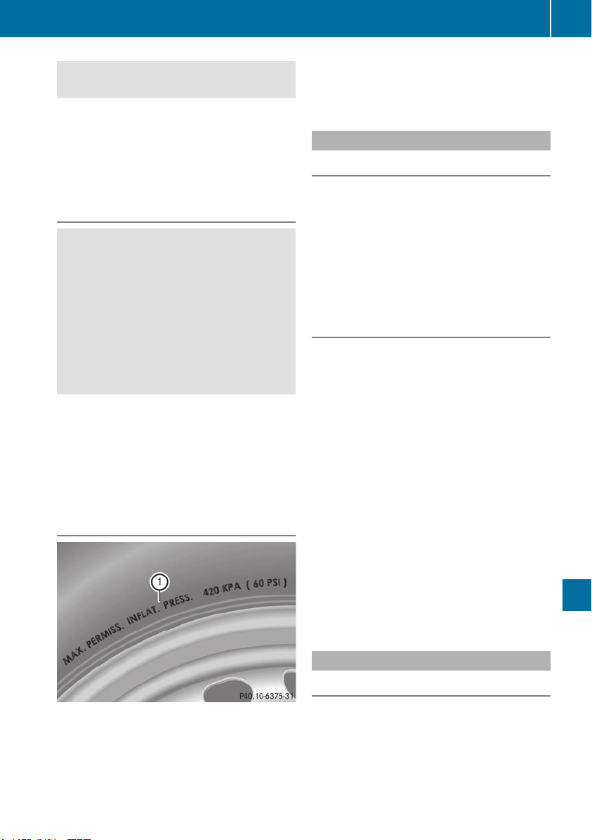
Avoid tire pressures that are too low in all the
tires, including the spare wheel.
Underinflated tires may:
R
overheat, leading to tire defects
R
adversely affect handling
R
wear excessively and/or unevenly
R
have an adverse effect on fuel consumption
Overinflated tires
G
WARNING
Tires with excessively high pressure can burst
because they are damaged more easily by
road debris, potholes etc. In addition, they
also suffer from irregular wear, which can
severely impair the braking properties and the
driving characteristics. There is a risk of an
accident.
Avoid tire pressures that are too high in all the
tires, including the spare wheel.
Overinflated tires may:
R
increase the braking distance
R
adversely affect handling
R
wear excessively and/or unevenly
R
have an adverse effect on ride comfort
R
be more susceptible to damage
Maximum tire pressures
:
Example: maximum permissible tire pres-
sure
Never exceed the maximum permissible tire
inflation pressure. Always observe the recom-
mended tire pressure for your vehicle when
adjusting the tire pressure (Y page 354).
i
The actual values for tires are vehicle-spe-
cific and may deviate from the values in the
illustration.
Checking the tire pressures
Important safety notes
Observe the notes on tire pressure
(Y page 354).
Information on air pressure for the tires on your
vehicle can be found:
R
on the Tire and Loading Information placard
on the B-pillar on the driver's side
R
in the tire pressure table in the fuel filler flap
R
in the "Tire pressure" section
Checking tire pressures manually
To determine and set the correct tire pressure,
proceed as follows:
X
Remove the valve cap of the tire that is to be
checked.
X
Press the tire pressure gage securely onto the
valve.
X
Read the tire pressure and compare it to the
recommended value on the Tire and Loading
Information placard or the tire pressure table
(Y page 354).
X
If the tire pressure is too low, increase the tire
pressure to the recommended value.
X
If the tire pressure is too high, release air. To
do so, press down the metal pin in the valve,
using the tip of a pen for example. Then check
the tire pressure again using the tire pressure
checker.
X
Screw the valve cap onto the valve.
X
Repeat these steps for the other tires.
Tire pressure loss warning system
General notes
While the vehicle is in motion, the tire pressure
loss warning system monitors the set tire pres-
sure using the rotational speed of the wheels.
This enables the system to detect significant
pressure loss in a tire. If the speed of rotation of
a wheel changes as a result of a loss of pressure,
Tire pressure
357
Wheels and tires
Z

a corresponding warning message will appear in
the multifunction display.
You can recognize the tire pressure loss warning
by the Run Flat Indicator Active PressRun Flat Indicator Active Press
'OK' to Restart'OK' to Restart message which appears in
the ServiceService menu of the multifunction display.
Information on the message display can be
found in the "Restarting the tire pressure loss
warning system" section (Y page 358).
Important safety notes
The tire pressure warning system does not warn
you of an incorrectly set tire pressure. Observe
the notes on the recommended tire pressure
(Y page 354).
The tire pressure loss warning does not replace
the need to regularly check the tire pressure. An
even loss of pressure on several tires at the
same time cannot be detected by the tire pres-
sure loss warning system.
The tire pressure monitor is not able to warn you
of a sudden loss of pressure, e.g. if the tire is
penetrated by a foreign object. In the event of a
sudden loss of pressure, bring the vehicle to a
halt by braking carefully. Avoid abrupt steering
movements.
The function of the tire pressure loss warning
system is limited or delayed if:
R
snow chains are mounted on your vehicle's
tires.
R
road conditions are wintry.
R
you are driving on sand or gravel.
R
you adopt a very sporty driving style (corner-
ing at high speeds or driving with high rates of
acceleration).
R
you are driving with a heavy load (in the vehi-
cle or on the roof).
Restarting the tire pressure loss warn-
ing system
Restart the tire pressure loss warning system if
you have:
R
changed the tire pressure
R
changed the wheels or tires
R
mounted new wheels or tires
X
Before restarting, make sure that the tire
pressures are set properly on all four tires for
the respective operating conditions.
The recommended tire pressure can be found
on the Tire and Loading Information placard
on the B-pillar. Additionally, a tire pressure
table is attached to the fuel filler flap. The tire
pressure loss warning system can only give
reliable warnings if you have set the correct
tire pressure. If an incorrect tire pressure is
set, these incorrect values will be monitored.
X
Also observe the notes in the section on tire
pressures (Y page 354).
X
Make sure that the SmartKey is in position 2
in the ignition lock (Y page 135).
X
Press the = or ; button on the steering
wheel to select the ServiceService menu.
X
Press the 9 or : button to select
Tire PressureTire Pressure.
X
Press the a button.
The Run Flat Indicator Active PressRun Flat Indicator Active Press
'OK' to Restart'OK' to Restart message appears in the
multifunction display.
If you wish to confirm the restart:
X
Press the a button.
The Tire Pressure Now OK?Tire Pressure Now OK? message
appears in the multifunction display.
X
Press the 9 or : button to select YesYes.
X
Press the a button.
The Run Flat Indicator RestartedRun Flat Indicator Restarted mes-
sage appears in the multifunction display.
After a teach-in period, the tire pressure loss
warning system will monitor the set tire pres-
sures of all four tires.
If you wish to cancel the restart:
X
Press the % button.
or
X
When the TireTire PressurePressure NowNow OK?OK? message
appears, press the 9 or : button to
select CancelCancel.
X
Press the a button.
The tire pressure values stored at the last
restart will continue to be monitored.
Tire pressure monitor
General notes
If a tire pressure monitor is installed, the vehi-
cle's wheels have sensors that monitor the tire
pressures in all four tires. The tire pressure mon-
itor warns you if the pressure drops in one or
more of the tires. The tire pressure monitor only
functions if the corresponding sensors are
installed in all wheels.
358
Tire pressure
Wheels and tires

Information on tire pressures is displayed in the
multifunction display. After a few minutes of
driving, the current tire pressure of each tire is
shown in the Serv.Serv. menu of the multifunction
display, see illustration (example).
For information on the message display, refer to
the "Checking the tire pressure electronically"
section (Y page 360).
Important safety notes
G
WARNING
Each tire, including the spare (if provided),
should be checked at least once a month
when cold and inflated to the pressure rec-
ommended by the vehicle manufacturer on
the Tire and Loading Information placard on
the driver's door B-pillar or the tire pressure
label on the inside of the fuel filler flap. If your
vehicle has tires of a different size than the
size indicated on the Tire and Loading Infor-
mation placard or the tire pressure label, you
should determine the proper tire pressure for
those tires.
As an added safety feature, your vehicle has
been equipped with a tire pressure monitoring
system (TPMS) that illuminates a low tire pres-
sure telltale when one or more of your tires
are significantly underinflated. Accordingly,
when the low tire pressure telltale illuminates,
you should stop and check your tires as soon
as possible, and inflate them to the proper
pressure. Driving on a significantly underin-
flated tire causes the tire to overheat and can
lead to tire failure. Underinflation also
reduces fuel efficiency and tire tread life, and
may affect the vehicle's handling and stop-
ping ability.
Please note that the TPMS is not a substitute
for proper tire maintenance, and it is the driv-
er's responsibility to maintain correct tire
pressure, even if underinflation has not
reached the level to trigger illumination of the
TPMS low tire pressure telltale.
USA only:
Your vehicle has also been equipped with a
TPMS malfunction indicator to indicate if the
system is not operating properly. The TPMS
malfunction indicator is combined with the
low tire pressure telltale. When the system
detects a malfunction, the warning lamp will
flash for approximately a minute and then
remain continuously illuminated. This
sequence will be repeated every time the vehi-
cle is started as long as the malfunction
exists.
When the malfunction indicator is illuminated,
the system may not be able to detect or signal
low tire pressure as intended. TPMS malfunc-
tions may occur for a variety of reasons,
including the mounting of incompatible
replacement or alternate tires or wheels on
the vehicle that prevent the TPMS from func-
tioning properly. Always check the TPMS mal-
function telltale after replacing one or more
tires or wheels on your vehicle to ensure that
the replacement or alternate tires and wheels
allow the TPMS to continue to function prop-
erly.
It is the driver's responsibility to set the tire
pressure to that recommended for cold tires
which is suitable for the operating situation
(Y page 354). Note that the correct tire pressure
for the current operating situation must first be
taught-in to the tire pressure monitor. If a sub-
stantial loss of pressure occurs, the warning
threshold for the warning message is aligned to
the taught-in reference values. Restart the tire
pressure monitor after adjusting the pressure of
the cold tires (Y page 361). The current pres-
sures are saved as new reference values. As a
result, a warning message will appear if the tire
pressure drops significantly.
The tire pressure monitor does not warn you of
an incorrectly set tire pressure. Observe the
notes on the recommended tire pressure
(Y page 354).
The tire pressure monitor is not able to warn you
of a sudden loss of pressure, e.g. if the tire is
penetrated by a foreign object. In the event of a
Tire pressure
359
Wheels and tires
Z

sudden loss of pressure, bring the vehicle to a
halt by braking carefully. Avoid abrupt steering
movements.
The tire pressure monitor has a yellow warning
lamp in the instrument cluster for indicating
pressure loss or a malfunction. Whether the
warning lamp flashes or lights up indicates
whether a tire pressure is too low or the tire
pressure monitor is malfunctioning:
R
if the warning lamp is lit continuously, the tire
pressure on one or more tires is significantly
too low. The tire pressure monitor is not mal-
functioning.
R
if the warning lamp flashes for approximately
a minute and then remains lit constantly, the
tire pressure monitor is malfunctioning.
In addition to the warning lamp, a message
appears in the multifunction display. Observe
the information on display messages
(Y page 268).
It may take up to ten minutes for a malfunction
of the tire pressure monitor to be indicated. A
malfunction will be indicated by the tire pres-
sure warning lamp flashing for approximately
one minute and then remaining lit. When the
malfunction has been rectified, the tire pressure
warning lamp goes out after a few minutes of
driving.
The tire pressure values indicated by the on-
board computer may differ from those meas-
ured at a gas station with a pressure gage. The
tire pressures shown by the on-board computer
refer to those measured at sea level. At high
altitudes, the tire pressure values indicated by a
pressure gage are higher than those shown by
the on-board computer. In this case, do not
reduce the tire pressures.
The operation of the tire pressure monitor can
be affected by interference from radio transmit-
ting equipment (e.g. radio headphones, two-way
radios) that may be being operated in or near the
vehicle.
Checking the tire pressure electroni-
cally
X
Make sure that the SmartKey is in position 2
(Y page 135) in the ignition lock.
X
Press the = or ; button on the steering
wheel to select the Serv.Serv. menu.
X
Press the 9 or : button to select
Tire PressureTire Pressure.
X
Press a.
The current tire pressure of each tire is shown
in the multifunction display.
If the vehicle has been parked for longer than
20 minutes, the Tire pressure will beTire pressure will be
displayed after driving a few minutesdisplayed after driving a few minutes
message appears.
After a teach-in process, the tire pressure mon-
itor automatically detects new wheels or new
sensors. As long as a clear allocation of the tire
pressure value to the individual wheels is not
possible, the TireTire PressurePressure MonitorMonitor ActiveActive
display message is shown instead of the tire
pressure display. The tire pressures are already
being monitored.
If an emergency spare wheel is mounted, the
system may continue to show the tire pressure
of the wheel that has been removed for a few
minutes. If this occurs, note that the value dis-
played for the position where the spare wheel is
mounted is not the same as the current tire
pressure of the emergency spare wheel.
Tire pressure monitor warning mes-
sages
If the tire pressure monitor detects a pressure
loss in one or more tires, a warning message is
shown in the multifunction display. The yellow
tire pressure warning lamp then lights up.
R
If the Please Correct Tire PressurePlease Correct Tire Pressure
message appears in the multifunction display,
the tire pressure in at least one tire is too low.
The tire pressure must be corrected when the
opportunity arises.
R
If the Check TiresCheck Tires message appears in the
multifunction display, the tire pressure in at
least one tire has dropped significantly. The
tires must be checked.
R
If the WarningWarning TireTire MalfunctionMalfunction message
appears in the multifunction display, the tire
pressure in at least one tire has dropped sud-
denly. The tires must be checked.
Be sure to observe the instructions and safety
notes in the display messages in the "Tires" sec-
tion (Y page 268).
If the wheel positions on the vehicle are rotated,
the tire pressures may be displayed for the
wrong positions for a short time. This is rectified
after a few minutes of driving, and the tire pres-
sures are displayed for the correct positions.
360
Tire pressure
Wheels and tires

Restarting the tire pressure monitor
When you restart the tire pressure monitor, all
existing warning messages are deleted and the
warning lamps go out. The monitor uses the cur-
rently set tire pressures as the reference values
for monitoring. In most cases, the tire pressure
monitor will automatically detect the new refer-
ence values after you have changed the tire
pressure. However, you can also set reference
values manually as described here. The tire
pressure monitor then monitors the new tire
pressure values.
X
Set the tire pressure to the value recommen-
ded for the corresponding driving situation on
the Tire and Loading Information placard on
the driver's side B-pillar (Y page 354).
You can find more tire pressure values for
various operating conditions in the tire pres-
sure table inside the fuel filler flap
(Y page 355).
X
Make sure that the tire pressure is correct on
all four wheels.
X
Make sure that the SmartKey is in position 2
in the ignition lock.
X
Press the = or ; button on the steering
wheel to select the Serv.Serv. menu.
X
Press the 9 or : button to select
Tire PressureTire Pressure.
X
Press a.
The multifunction display shows the current
tire pressure for the individual tires or the
Tire pressure will be displayedTire pressure will be displayed
after driving a few minutesafter driving a few minutes message.
X
Press the : button.
The UseUse CurrentCurrent PressuresPressures asas NewNew Ref‐Ref‐
erenceerence ValuesValues message appears in the mul-
tifunction display.
If you wish to confirm the restart:
X
Press the a button.
The TireTire Press.Press. MonitorMonitor RestartedRestarted mes-
sage appears in the multifunction display.
After driving for a few minutes, the system
checks whether the current tire pressures are
within the specified range. The new tire pres-
sures are then accepted as reference values
and monitored.
If you wish to cancel the restart:
X
Press the % button.
The tire pressure values stored at the last
restart will continue to be monitored.
Radio type approval for the tire pres-
sure monitor
Country Radio type approval number
USA FCC ID: MRXMW2433A
FCC ID: MRXGG4
FCC ID: MRXMC34MA4
Canada IC: 2546A-MW2433A
IC: 2546A-GG4
IC: 2546A-MC34MA4
Loading the vehicle
Instruction labels for tires and loads
G
WARNING
Overloaded tires can overheat, causing a
blowout. Overloaded tires can also impair the
steering and driving characteristics and lead
to brake failure. There is a risk of accident.
Observe the load rating of the tires. The load
rating must be at least half of the GAWR of
your vehicle. Never overload the tires by
exceeding the maximum load.
Two instruction labels on your vehicle show the
maximum possible load.
(1) The Tire and Loading Information placard is
on the B-pillar on the driver's side. The Tire
and Loading Information placard shows the
maximum permissible number of occu-
pants and the maximum permissible vehicle
load. It also contains details of the tire sizes
and corresponding pressures for tires
mounted at the factory.
(2) The vehicle identification plate is on the B-
pillar on the driver's side. The vehicle iden-
tification plate informs you of the gross
vehicle weight rating. It is made up of the
vehicle weight, all vehicle occupants, the
fuel and the cargo. You can also find infor-
mation about the maximum gross axle
weight rating on the front and rear axle.
The maximum gross axle weight rating is
the maximum weight that can be carried by
one axle (front or rear axle). Never exceed
the maximum load or the maximum gross
axle weight rating for the front or rear axle.
Loading the vehicle
361
Wheels and tires
Z
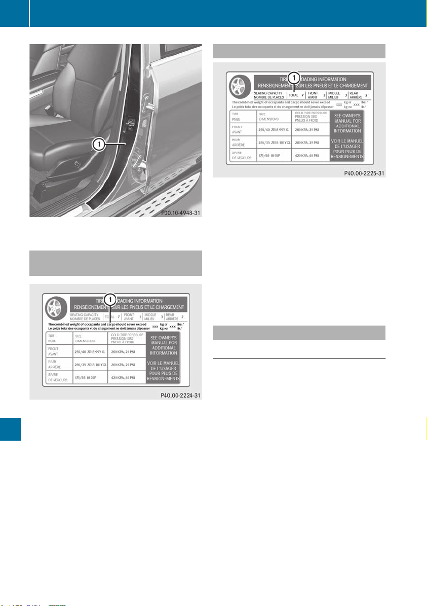
:
B-pillar, driver's side
Maximum permissible gross vehicle
weight rating
X
Specification for maximum gross vehicle
weight : is listed in the Tire and Loading
Information placard: "The combined weight of
occupants and cargo should never exceed
XXX kilograms or XXX lbs."
The gross weight of all vehicle occupants, load
and luggage must not exceed the specified
value.
i
The specifications shown on the Tire and
Loading Information placard in the illustration
are examples. The maximum permissible
gross vehicle weight rating is vehicle-specific
and may differ from that in the illustration.
You can find the valid maximum permissible
gross vehicle weight rating for your vehicle on
the Tire and Loading Information placard.
Number of seats
Maximum number of seats : indicates the
maximum number of occupants allowed to
travel in the vehicle. This information can be
found on the Tire and Loading Information plac-
ard.
i
The specifications shown on the Tire and
Loading Information placard in the illustration
are examples. The number of seats is vehicle-
specific and can differ from the details shown.
The number of seats in your vehicle can be
found on the Tire and Loading Information
placard.
Determining the correct load limit
Step-by-step instructions
The following steps have been developed as
required of all manufacturers under Title 49,
Code of U.S. Federal Regulations, Part 575 pur-
suant to the "National Traffic and Motor Vehicle
Safety Act of 1966".
X
Step 1: Locate the statement "The combined
weight of occupants and cargo should never
exceed XXX kg or XXX lbs." on your vehicle’s
Tire and Loading Information placard.
X
Step 2: Determine the combined weight of
the driver and passengers that will be riding in
your vehicle.
X
Step 3: Subtract the combined weight of the
driver and passengers from XXX kilograms or
XXX lbs.
X
Step 4: The resulting figure equals the avail-
able amount of cargo and luggage load capa-
city. For example, if the "XXX" amount equals
1400 lbs and there will be five 150-lb pas-
sengers in your vehicle, the amount of avail-
362
Loading the vehicle
Wheels and tires

able cargo and luggage load capacity is
650 lbs (1400 - 750 (5 x 150) = 650 lbs).
X
Step 5: Determine the combined weight of
luggage and cargo being loaded on the vehi-
cle. That weight may not safely exceed the
available cargo and luggage load capacity cal-
culated in step 4.
Example: steps 1 to 3
The following table shows examples on how to calculate total and cargo load capacities with varying
seating configurations and number and size of occupants. The following examples use a load limit of
1500 lbs (680 kg). This is for illustration purposes only. Make sure you are using the actual load
limit for your vehicle stated on your vehicle's Tire and Loading Information placard (Y page 361).
The greater the combined weight of the occupants, the lower the maximum luggage load.
Additional information when towing a trailer (Y page 221).
Step 1
Example 1 Example 2 Example 3
Combined maximum
weight of occupants
and cargo (data from
the Tire and Loading
Information placard)
1500 lbs (680 kg) 1500 lbs (680 kg) 1500 lbs (680 kg)
Step 2
Example 1 Example 2 Example 3
Number of people in
the vehicle (driver and
occupants)
5 3 1
Distribution of the
occupants
Front: 2
Rear: 3
Front: 1
Rear: 2
Front: 1
Weight of the occu-
pants
Occupant 1: 150 lbs
(68 kg)
Occupant 2: 180 lbs
(82 kg)
Occupant 3: 160 lbs
(73 kg)
Occupant 4: 140 lbs
(63 kg)
Occupant 5: 120 lbs
(54 kg)
Occupant 1: 200 lbs
(91 kg)
Occupant 2: 190 lbs
(86 kg)
Occupant 3: 150 lbs
(68 kg)
Occupant 1: 150 lbs
(68 kg)
Gross weight of all
occupants
750 lbs (340 kg) 540 lbs (245 kg) 150 lbs (68 kg)
Loading the vehicle
363
Wheels and tires
Z
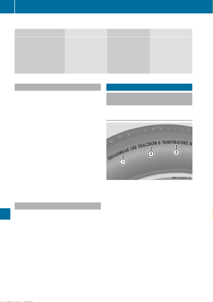
Step 3
Example 1 Example 2 Example 3
Permissible load (maxi-
mum gross vehicle
weight rating from the
Tire and Loading Infor-
mation placard minus
the gross weight of all
occupants)
1500 lbs (680 kg) Ò
750 lbs (340 kg) =
750 lbs (340 kg)
1500 lbs (680 kg) Ò
540 lbs (245 kg)
=960 lbs (435 kg)
1500 lbs (680 kg) Ò
150 lbs (68 kg) =
1350 lbs (612 kg)
Vehicle identification plate
Even if you have calculated the total cargo care-
fully, you should still make sure that the gross
vehicle weight rating and the gross axle weight
rating are not exceeded. Details can be found on
the vehicle identification plate on the B-pillar on
the driver's side of the vehicle (Y page 361).
Permissible Gross Vehicle Weight Rating
(GVWR): the gross weight of the vehicle, all pas-
sengers, load and trailer load/noseweight (if
applicable) must not exceed the permissible
gross vehicle weight.
Gross Axle Weight Rating (GAWR): the maxi-
mum permissible weight that can be carried by
one axle (front or rear axle).
To ensure that your vehicle does not exceed the
maximum permissible values (gross vehicle
weight and maximum gross axle weight rating),
have your loaded vehicle (including driver, occu-
pants, cargo, and full trailer load if applicable)
weighed on a suitable vehicle weighbridge.
Trailer load/noseweight
The trailer load/noseweight affects the gross
weight of the vehicle. If a trailer is attached, the
trailer load/noseweight is included in the load
along with occupants and luggage. The trailer
load/noseweight is usually approximately 8% of
the gross weight of the trailer and its cargo.
All about wheels and tires
Uniform Tire Quality Grading Stand-
ards
Overview of Tire Quality Grading Stand-
ards
Uniform Tire Quality Grading Standards are U.S.
government specifications. Their purpose is to
provide drivers with uniform reliable information
on tire performance data. Tire manufacturers
have to grade tires using three performance fac-
tors: : tread wear grade, ; traction grade and
= temperature grade. These regulations do not
apply to Canada. Nevertheless, all tires sold in
North America are provided with the corre-
sponding quality grading markings on the side-
wall of the tire.
Quality grades can be found, where applicable,
on the tire sidewall between tread shoulder and
maximum section width.
Example:
R
Treadwear grade: 200
R
Traction grade: AA
R
Temperature grade: A
364
All about wheels and tires
Wheels and tires

All passenger car tires must conform to the stat-
utory safety requirements in addition to these
grades.
i
The actual values for tires are vehicle-spe-
cific and may deviate from the values in the
illustration.
Treadwear
The treadwear grade is a comparative rating
based on the wear rate of the tire when tested
under controlled conditions on a specified U.S.
government course. For example, a tire graded
150 would wear one and one-half times as well
on the government course as a tire graded 100.
The relative performance of tires depends upon
the actual conditions of their use, however, and
may depart significantly from the norm due to
variations in driving habits, service practices
and differences in road characteristics and cli-
mate.
Traction
G
WARNING
The traction grade assigned to this tire is
based on straight-ahead braking traction
tests, and does not include acceleration, cor-
nering, hydroplaning, or peak traction char-
acteristics.
!
Avoid wheelspin. This can lead to damage to
the drive train.
The traction grades – from highest to lowest –
are AA, A, B and C. Those grades represent the
tire's ability to stop on wet pavement as meas-
ured under controlled conditions on specified
government test surfaces of asphalt and con-
crete. A tire marked C may have poor traction
performance.
The safe speed on a wet, snow covered or icy
road is always lower than on dry road surfaces.
You should pay special attention to road condi-
tions when temperatures are around freezing
point.
Mercedes-Benz recommends a minimum tread
depth of ã in (4 mm) on all four winter tires.
Observe the legally required minimum tire tread
depth (Y page 352). Winter tires can reduce the
braking distance on snow-covered surfaces in
comparison with summer tires. The braking dis-
tance is still much further than on surfaces that
are not icy or covered with snow. Take appro-
priate care when driving.
Further information on winter tires (M+S tires)
(Y page 353).
Temperature
G
WARNING
The temperature grade for this tire is estab-
lished for a tire that is properly inflated and
not overloaded. Excessive speed, underinfla-
tion, or excessive loading, either separately or
in combination, can cause excessive heat
build-up and possible tire failure.
The temperature grades are A (the highest), B,
and C, representing the tire's resistance to the
generation of heat and its ability to dissipate
heat when tested under controlled conditions
on a specified indoor laboratory test wheel. Sus-
tained high temperature can cause the material
of the tire to degenerate and reduce tire life, and
excessive temperature can lead to sudden tire
failure. The grade C corresponds to a level of
performance which all passenger car tires must
meet under the Federal Motor Vehicle Safety
Standard No. 109. Grades B and A represent
higher levels of performance on the laboratory
test wheel than the minimum required by law.
All about wheels and tires
365
Wheels and tires
Z
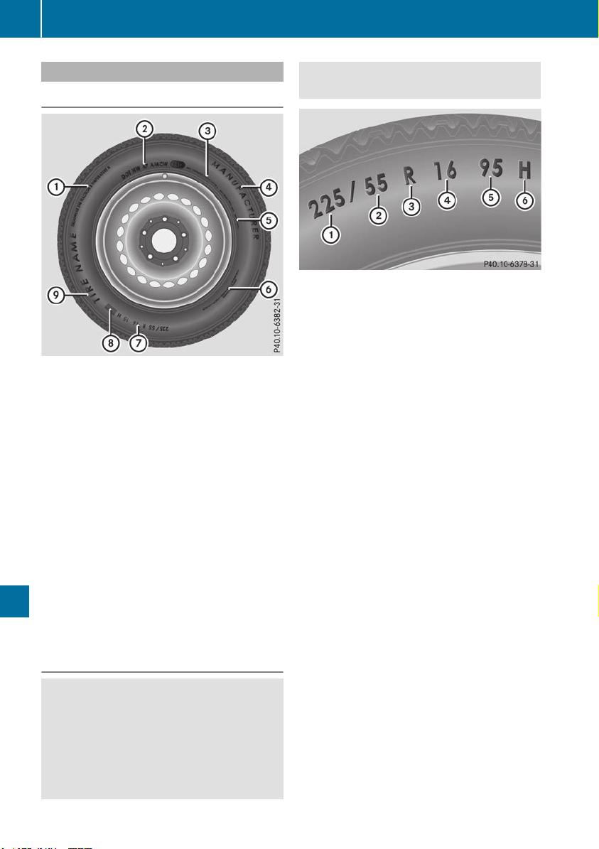
Tire labeling
Overview
:
Uniform Tire Quality Grading Standards
(Y page 369)
;
Department of Transportation, Tire Identifi-
cation Number (Y page 368)
=
Maximum load rating (Y page 368)
?
Maximum tire pressures (Y page 357)
A
Manufacturer
B
Tire material (Y page 369)
C
Tire size designation, load-bearing capacity
and speed rating (Y page 366)
D
Load index (Y page 368)
E
Tire name
The markings described above are on the tire in
addition to the tire name (sales designation) and
the manufacturer's name.
i
Tire data is vehicle-specific and may deviate
from the data in the example.
Tire size designation, load-bearing
capacity and speed rating
G
WARNING
Exceeding the stated tire load-bearing capa-
city and the approved maximum speed could
lead to tire damage or the tire bursting. There
is a risk of accident.
Therefore, only use tire types and sizes
approved for your vehicle model. Observe the
tire load rating and speed rating required for
your vehicle.
:
Tire width
;
Nominal aspect ratio in %
=
Tire code
?
Rim diameter
A
Load bearing index
B
Speed rating
General: depending on the manufacturer's
standards, the size imprinted in the tire wall may
not contain any letters or may contain one letter
that precedes the size description.
If there is no letter preceding the size descrip-
tion (as shown above): these are passenger
vehicle tires according to European manufac-
turing standards.
If "P" precedes the size description: these are
passenger vehicle tires according to U.S. man-
ufacturing standards.
If "LT" precedes the size description: these are
light truck tires according to U.S. manufacturing
standards.
If "T" precedes the size description: compact
emergency wheels with high tire pressure that
are only designed for temporary use in an emer-
gency.
Tire width: tire width : shows the nominal tire
width in millimeters.
Height-width ratio: aspect ratio ; is the size
ratio between the tire height and tire width and
is shown in percent. The aspect ratio is calcula-
ted by dividing the tire width by the tire height.
Tire code: tire code = specifies the tire type.
"R" represents radial tires; "D" represents diag-
onal tires; "B" represents diagonal radial tires.
Optionally, tires with a maximum speed of over
149 mph (240 km/h) may have "ZR" in the size
366
All about wheels and tires
Wheels and tires

description, depending on the manufacturer
(e.g. 245/40 ZR 18).
Rim diameter: rim diameter ? is the diameter
of the bead seat, not the diameter of the rim
flange. The rim diameter is specified in
inches (in).
Load-bearing index: load-bearing index A is a
numerical code that specifies the maximum
load-bearing capacity of a tire.
Do not overload the tires by exceeding the
specified load limit. The maximum permissible
load can be found on the vehicle's Tire and
Loading Information placard on the B-pillar on
the driver's side (Y page 361).
Example:
Load-bearing index 91 indicates a maximum
load of 1,356 lb (615 kg) that the tires can bear.
For further information on the maximum tire
load in kilograms and lbs, see (Y page 368).
For further information on the load bearing
index, see "Load index" (Y page 368).
Speed rating: speed rating B specifies the
approved maximum speed of the tire.
i
Tire data is vehicle-specific and may deviate
from the data in the example.
Regardless of the speed rating, always observe
the speed limits. Drive carefully and adapt your
driving style to the traffic conditions.
Summer tires
Index Speed rating
Q up to 100 mph (160 km/h)
R up to 106 mph (170 km/h)
S up to 112 mph (180 km/h)
T up to 118 mph (190 km/h)
H up to 130 mph (210 km/h)
V up to 149 mph (240 km/h)
W up to 168 mph (270 km/h)
Y up to 186 mph (300 km/h)
ZR...Y up to 186 mph (300 km/h)
ZR...(..Y) over 186 mph (300 km/h)
ZR over 149 mph (240 km/h)
R
Optionally, tires with a maximum speed of
over 149 mph (240 km/h) may have "ZR" in
the size description, depending on the man-
ufacturer (e.g. 245/40 ZR18).
The service specification is made up of load-
bearing index A and speed rating B.
R
If the size description of your tire includes
"ZR" and there are no service specifications,
ask the tire manufacturer in order to find out
the maximum speed.
If a service specification is available, the max-
imum speed is limited according to the speed
rating in the service specification. Example:
245/40 ZR18 97 Y. In this example, "97 Y" is
the service specification. The letter "Y" rep-
resents the speed rating. The maximum
speed of the tire is limited to 186 mph
(300 km/h).
R
The size description for all tires with maxi-
mum speeds of over 186 mph (300 km/h)
must include "ZR", and the service specifica-
tion must be given in parentheses. Example:
275/40 ZR 18 (99 Y). Speed rating "(Y)" indi-
cates that the maximum speed of the tire is
over 186 mph (300 km/h). Ask the tire man-
ufacturer about the maximum speed.
All-weather tires and winter tires
Index Speed rating
Q M+S
3
up to 100 mph (160 km/h)
T M+S
3
up to 118 mph (190 km/h)
H M+S
3
up to 130 mph (210 km/h)
V M+S
3
up to 149 mph (240 km/h)
i
Not all tires with the M+S marking provide
the driving characteristics of winter tires. In
addition to the M+S marking, winter tires also
have the i snowflake symbol on the tire
wall. Tires with this marking fulfill the require-
ments of the Rubber Manufacturers Associa-
tion (RMA) and the Rubber Association of
Canada (RAC) regarding the tire traction on
snow. They have been especially developed
for driving on snow.
3
Or M+S i for winter tires.
All about wheels and tires
367
Wheels and tires
Z
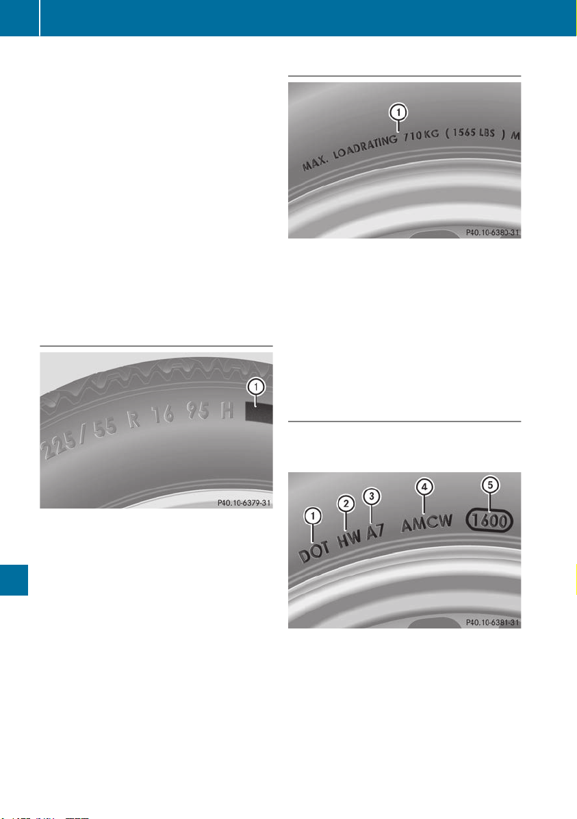
An electronic speed limiter prevents your vehi-
cle from exceeding the following speeds:
R
All vehicles (except Mercedes-AMG GLE 63):
130 mph (210 km/h)
R
Mercedes-AMG GLE 63 vehicles: 155 mph
(250 km/h)
R
Mercedes-AMG GLE 63 with increased top
speed: 174 mph (280 km/h)
The speed rating of tires mounted at the factory
may be higher than the maximum speed that the
electronic speed limiter permits.
Make sure that your tires have the required
speed rating, e.g. when buying new tires. The
required speed rating for your vehicle can be
found in the "Tires" section (Y page 376).
Further information about reading tire data can
be obtained from any qualified specialist work-
shop.
Load index
In addition to the load bearing index, load
index : may be imprinted after the letters that
identify speed index B on the sidewall of the
tire (Y page 366).
R
If no specification is given: no text (as in the
example above), represents a standard load
(SL) tire
R
XL or Extra Load: represents a reinforced tire
R
Light Load: represents a light load tire
R
C, D, E: represents a load range that depends
on the maximum load that the tire can carry at
a certain pressure
i
Tire data is vehicle-specific and may deviate
from the data in the example.
Maximum load rating
Maximum tire load : is the maximum permis-
sible weight for which the tire is approved.
Do not overload the tires by exceeding the
specified load limit. The maximum permissible
load can be found on the vehicle's Tire and
Loading Information placard on the B-pillar on
the driver's side (Y page 361).
i
The actual values for tires are vehicle-spe-
cific and may deviate from the values in the
illustration.
DOT, Tire Identification Number (TIN)
US tire regulations stipulate that every tire man-
ufacturer or retreader must imprint a TIN in or on
the sidewall of each tire produced.
The TIN is a unique identification number. The
TIN enables the tire manufacturers or retreaders
to inform purchasers of recalls and other safety-
relevant matters. It makes it possible for the
purchaser to easily identify the affected tires.
The TIN is made up of manufacturer identifica-
tion code ;, tire size =, tire type code ? and
manufacturing date A.
DOT (Department of Transportation): tire
symbol : marks that the tire complies with the
368
All about wheels and tires
Wheels and tires
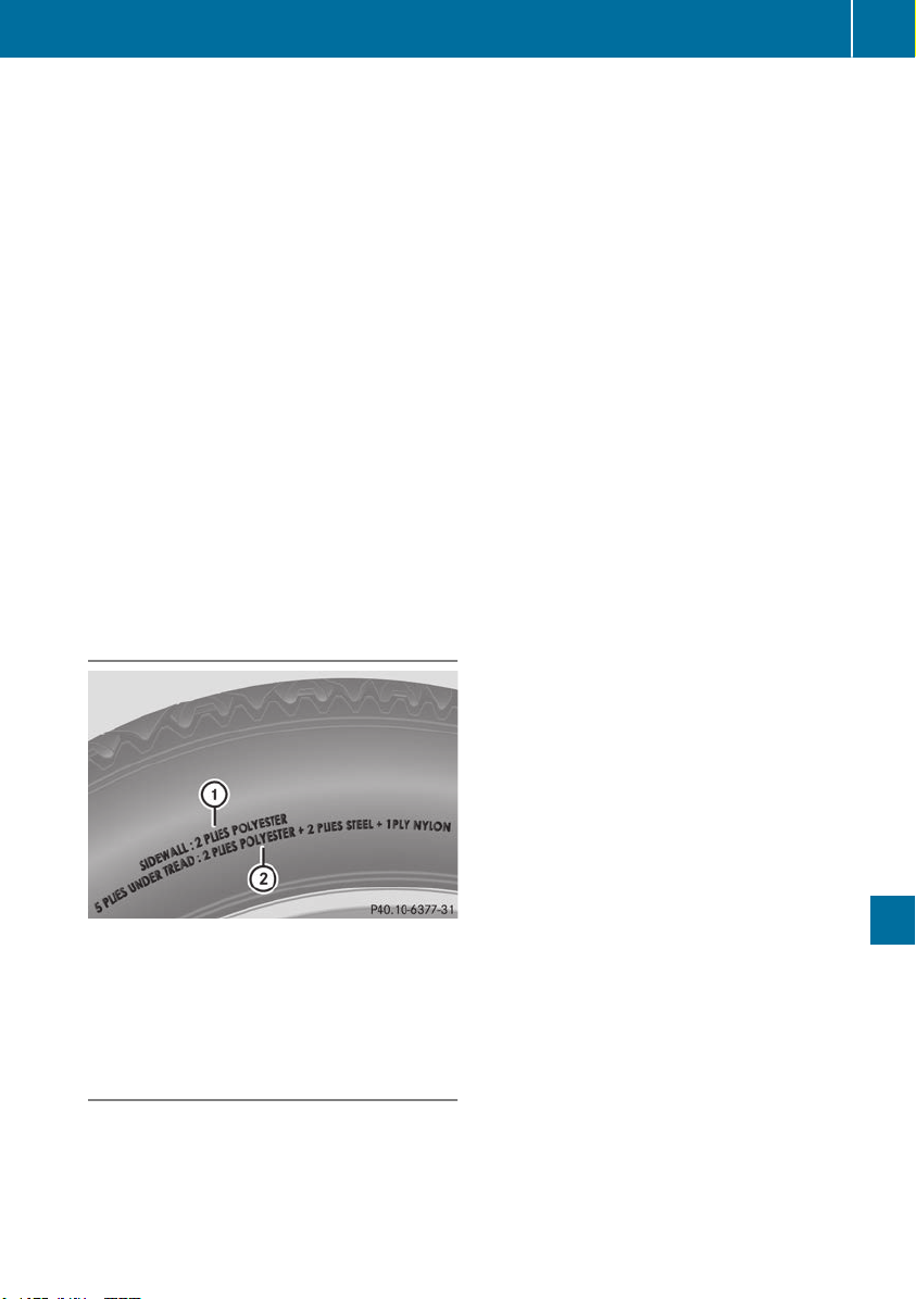
requirements of the U.S. Department of Trans-
portation.
Manufacturer identification code: manufac-
turer identification code ; provides details on
the tire manufacturer. New tires have a code
with two symbols. Retreaded tires have a code
with four symbols.
For further information about retreaded tires,
see (Y page 376).
Tire size: identifier = describes the tire size.
Tire type code: tire type code ? can be used by
the manufacturer as a code to describe specific
characteristics of the tire.
Date of manufacture: date of manufacture A
provides information about the age of a tire. The
first and second positions represent the week of
manufacture, starting with "01" for the first cal-
endar week. Positions three and four represent
the year of manufacture. For example, a tire that
is marked "3214" was manufactured in week 32
in 2014.
i
Tire data is vehicle-specific and may deviate
from the data in the example.
Tire characteristics
This information describes the type of tire cord
and the number of layers in sidewall : and
under tire tread ;.
i
Tire data is vehicle-specific and may deviate
from the data in the example.
Definition of terms for tires and loading
Tire ply composition and material used
Describes the number of plies or the number of
layers of rubber-coated fabric in the tire tread
and sidewall. These are made of steel, nylon,
polyester and other materials.
Bar
Metric unit for tire pressure. 14.5038 pounds
per square inch (psi) and 100 kilopascals (kPa)
are the equivalent of 1 bar.
DOT (Department of Transportation)
DOT-marked tires fulfill the requirements of the
U S Department of Transportation.
Normal occupant weight
The number of occupants for which the vehicle
is designed multiplied by 68 kilograms (150 lbs).
Uniform Tire Quality Grading Standards
A uniform standard to grade the quality of tires
with regards to tread quality, tire traction and
temperature characteristics. The quality grad-
ing assessment is made by the manufacturer
following specifications from the U.S. govern-
ment. The ratings are molded into the sidewall of
the tire.
Recommended tire pressures
The recommended tire pressure applies to the
tires mounted at the factory.
The Tire and Loading Information placard con-
tains the recommended tire pressures for cold
tires on a fully loaded vehicle and for the maxi-
mum permissible vehicle speed.
The tire pressure table contains the recommen-
ded pressures for cold tires for various operat-
ing conditions, i.e. differing load and speed con-
ditions.
Increased vehicle weight due to optional
equipment
The combined weight of all standard and
optional equipment available for the vehicle,
regardless of whether it is actually installed on
the vehicle or not.
Rim
This is the part of the wheel on which the tire is
mounted.
GAWR (Gross Axle Weight Rating)
The GAWR is the maximum gross axle weight
rating. The actual load on an axle must never
exceed the gross axle weight rating. The gross
axle weight rating can be found on the vehicle
identification plate on the B-pillar on the driver's
side.
All about wheels and tires
369
Wheels and tires
Z

Speed rating
The speed rating is part of the tire identification.
It specifies the speed range for which the tire is
approved.
GTW (Gross Trailer Weight)
The GTW is the weight of a trailer including the
weight of the load, luggage, accessories etc. on
the trailer.
GVW (Gross Vehicle Weight)
The gross vehicle weight includes the weight of
the vehicle including fuel, tools, the spare wheel,
accessories installed, occupants, luggage and
the drawbar noseweight, if applicable. The gross
vehicle weight must not exceed the gross vehi-
cle weight rating GVWR as specified on the vehi-
cle identification plate on the B-pillar on the
driver's side.
GVWR (Gross Vehicle Weight Rating)
The GVWR is the maximum permissible gross
weight of a fully loaded vehicle (the weight of the
vehicle including all accessories, occupants,
fuel, luggage and the drawbar noseweight, if
applicable). The gross vehicle weight rating is
specified on the vehicle identification plate on
the B-pillar on the driver's side.
Maximum loaded vehicle weight
The maximum weight is the sum of:
R
the curb weight of the vehicle
R
the weight of the accessories
R
the load limit
R
the weight of the factory installed optional
equipment
Kilopascal (kPa)
Metric unit for tire pressure. 6.9 kPa corre-
sponds to 1 psi. Another unit for tire pressure is
bar. 100 kilopascals (kPa) are the equivalent of
1 bar.
Load index
In addition to the load-bearing index, the load
index may also be imprinted on the sidewall of
the tire. This specifies the load-bearing capacity
more precisely.
Curb weight
The weight of a vehicle with standard equipment
including the maximum capacity of fuel, oil and
coolant. It also includes the air-conditioning sys-
tem and optional equipment if these are instal-
led in the vehicle, but does not include passen-
gers or luggage.
Maximum load rating
The maximum tire load is the maximum permis-
sible weight in kilograms or lbs for which a tire is
approved.
Maximum permissible tire pressure
Maximum permissible tire pressure for one tire.
Maximum load on one tire
Maximum load on one tire. This is calculated by
dividing the maximum axle load of one axle by
two.
PSI (pounds per square inch)
A standard unit of measure for tire pressure.
Aspect ratio
Relationship between tire height and tire width
in percent.
Tire pressure
This is pressure inside the tire applying an out-
ward force to each square inch of the tire's sur-
face. The tire pressure is specified in pounds per
square inch (psi), in kilopascal (kPa) or in bar.
The tire pressure should only be corrected when
the tires are cold.
Cold tire pressure
The tires are cold:
R
if the vehicle has been parked with the tires
out of direct sunlight for at least three hours
and
R
if the vehicle has not been driven further than
1 mile (1.6 km)
Tread
The part of the tire that comes into contact with
the road.
Bead
The tire bead ensures that the tire sits securely
on the wheel. There are several steel wires in the
bead to prevent the tire from coming loose from
the wheel rim.
370
All about wheels and tires
Wheels and tires

Sidewall
The part of the tire between the tread and the
bead.
Weight of optional extras
The combined weight of those optional extras
that weigh more than the replaced standard
parts and more than 2.3 kg (5 lbs). These
optional extras, such as high-performance
brakes, level control, a roof rack or a high-per-
formance battery, are not included in the curb
weight and the weight of the accessories.
TIN (Tire Identification Number)
This is a unique identifier which can be used by
a tire manufacturer to identify tires, for example
for a product recall, and thus identify the pur-
chasers. The TIN is made up of the manufactur-
er's identity code, tire size, tire type code and
the manufacturing date.
Load bearing index
The load bearing index (also load index) is a code
that contains the maximum load bearing capa-
city of a tire.
Traction
Traction is the result of friction between the tires
and the road surface.
TWR (Tongue Weight Rating)
The TWR specifies the maximum permissible
weight that the ball coupling of the trailer tow
hitch can support.
Treadwear indicators
Narrow bars (tread wear bars) that are distrib-
uted over the tire tread. If the tire tread is level
with the bars, the wear limit of á in (1.6 mm)
has been reached.
Occupant distribution
The distribution of occupants in a vehicle at their
designated seating positions.
Total load limit
Nominal load and luggage load plus 68 kg
(150 lbs) multiplied by the number of seats in
the vehicle.
Changing a wheel
Flat tire
The "Breakdown assistance" section
(Y page 335) contains information and notes on
how to deal with a flat tire. Information on driv-
ing with MOExtended tires in the event of a flat
tire can be found under "MOExtended tires (tires
with run-flat characteristics" (Y page 336).
Vehicles with an emergency spare wheel: in
the event of a flat tire, mount the emergency
spare wheel according to the description under
"Mounting a wheel" (Y page 372).
Rotating the wheels
G
WARNING
Interchanging the front and rear wheels may
severely impair the driving characteristics if
the wheels or tires have different dimensions.
The wheel brakes or suspension components
may also be damaged. There is a risk of acci-
dent.
Rotate front and rear wheels only if the wheels
and tires are of the same dimensions.
!
On vehicles equipped with a tire pressure
monitor, electronic components are located
in the wheel.
Tire-mounting tools should not be used near
the valve. This could damage the electronic
components.
Only have tires changed at a qualified spe-
cialist workshop.
Always observe the instructions and safety
notes in the "Mounting a wheel" section
(Y page 372).
The wear patterns on the front and rear tires
differ, depending on the operating conditions.
Rotate the wheels before a clear wear pattern
has formed on the tires. Front tires typically
wear more on the shoulders and the rear tires in
the center.
On vehicles that have the same size front and
rear wheels, you can rotate the wheels accord-
ing to the intervals in the tire manufacturer's
warranty book in your vehicle documents. If no
warranty book is available, the tires should be
rotated every 3,000 to 6,000 miles (5,000 to
10,000 km). Depending on tire wear, this may
Changing a wheel
371
Wheels and tires
Z
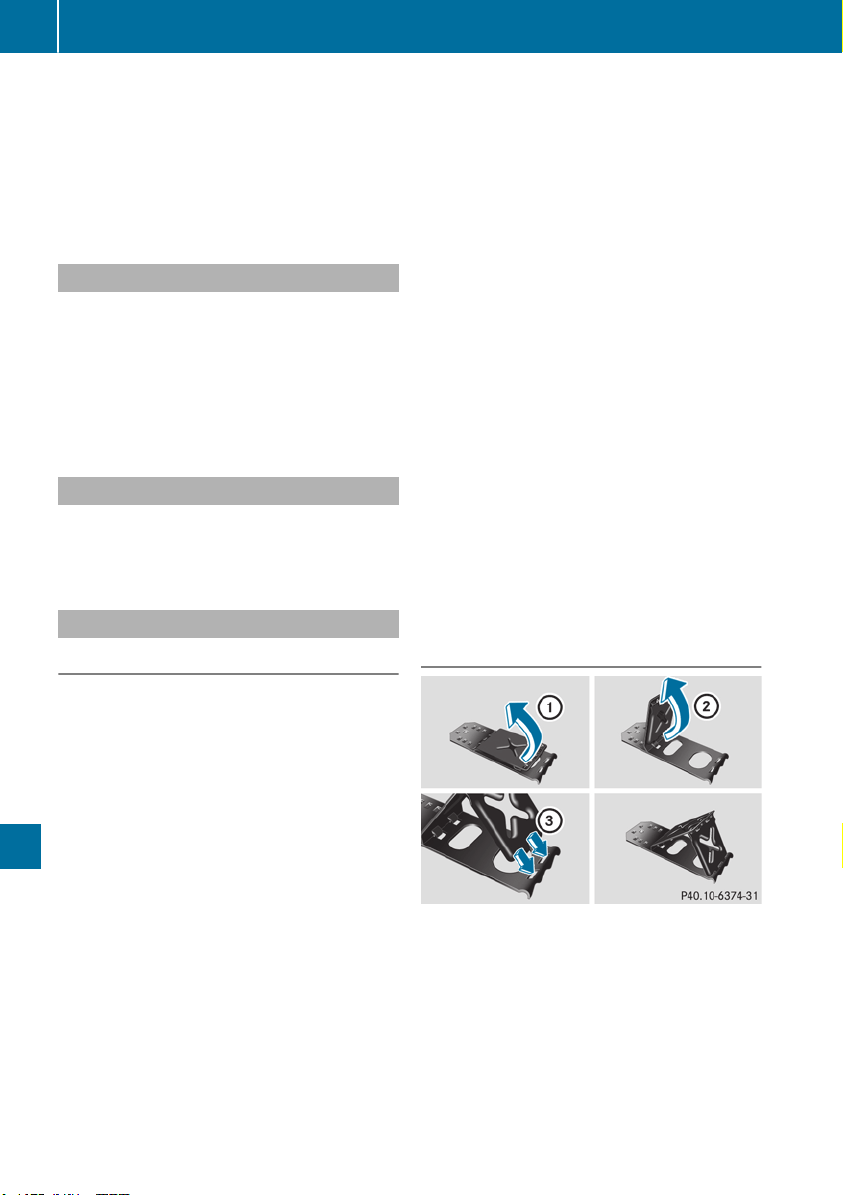
be required earlier. Do not change the direction
of wheel rotation.
Clean the contact surfaces of the wheel and the
brake disc thoroughly every time a wheel is rota-
ted. Check the tire pressure and, if necessary,
restart the tire pressure loss warning system or
the tire pressure monitor (Y page 358).
Direction of rotation
Tires with a specified direction of rotation have
additional benefits, e.g. if there is a risk of hydro-
planing. These advantages can only be gained if
the tires are installed corresponding to the
direction of rotation.
An arrow on the sidewall of the tire indicates its
correct direction of rotation.
Storing wheels
Store wheels that are not being used in a cool,
dry and preferably dark place. Protect the tires
from oil, grease, gasoline and diesel.
Mounting a wheel
Preparing the vehicle
X
Vehicle with emergency spare wheel:
when mounting the emergency spare wheel in
the event of a flat tire, follow the additional
notes on vehicle preparation under "Flat tire"
(Y page 335).
X
Stop the vehicle on solid, non-slippery and
level ground.
X
Apply the electric parking brake manually.
X
Bring the front wheels into the straight-ahead
position.
X
Vehicles with automatic transmission:
shift the transmission to position j.
X
Vehicles with the AIRMATIC package:
make sure that the normal vehicle level is
selected (Y page 185).
X
Vehicles with the Off-Road Engineering
package: make sure that the normal vehicle
level is selected (Y page 179).
X
Switch off the engine.
X
Vehicles without KEYLESS-GO: remove the
SmartKey from the ignition lock.
X
Vehicles with KEYLESS-GO: open the driv-
er's door.
The vehicle electronics are now in position
u. This means no SmartKey is in the ignition
lock.
X
Vehicles with KEYLESS-GO: remove the
Start/Stop button from the ignition lock
(Y page 135).
X
Make sure that the engine cannot be started
via your smartphone (Y page 137).
X
If included in the vehicle equipment, remove
the tire-change tool kit from the vehicle.
X
Safeguard the vehicle against rolling away.
i
Apart from certain country-specific varia-
tions, vehicles are not equipped with a tire-
change tool kit. For more information on
which tools are required to perform a wheel
change on your vehicle, consult a qualified
specialist workshop.
Necessary tire-changing tools can include, for
example:
R
Jack
R
Wheel chock
R
Lug wrench
Securing the vehicle to prevent it from
rolling away
If your vehicle is equipped with a wheel chock, it
can be found in the tire-change tool kit
(Y page 335).
The folding wheel chock is an additional safety
measure to prevent the vehicle from rolling
away, for example when changing a wheel.
X
Fold both plates upwards :.
X
Fold out lower plate ;.
X
Guide the lugs on the lower plate fully into the
openings in base plate =.
372
Changing a wheel
Wheels and tires
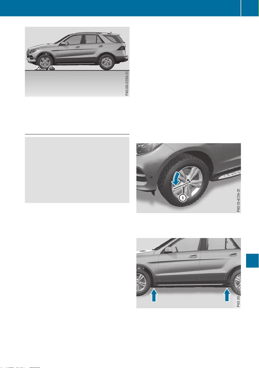
X
Place chocks or other suitable items under
the front and rear of the wheel that is diago-
nally opposite the wheel you wish to change.
Raising the vehicle
G
WARNING
If you do not position the jack correctly at the
appropriate jacking point of the vehicle, the
jack could tip over with the vehicle raised.
There is a risk of injury.
Only position the jack at the appropriate jack-
ing point of the vehicle. The base of the jack
must be positioned vertically, directly under
the jacking point of the vehicle.
!
Only position the jack at the appropriate
jacking point of the vehicle. Otherwise, you
could damage the vehicle.
Observe the following when raising the vehi-
cle:
R
To raise the vehicle, only use the vehicle-spe-
cific jack that has been tested and approved
by Mercedes-Benz. If used incorrectly, the
jack could tip over with the vehicle raised.
R
The jack is designed only to raise and hold the
vehicle for a short time while a wheel is being
changed. It must not be used for performing
maintenance work under the vehicle.
R
Avoid changing the wheel on uphill and down-
hill slopes.
R
Before raising the vehicle, secure it from roll-
ing away by applying the parking brake and
inserting wheel chocks. Do not disengage the
parking brake while the vehicle is raised.
R
The jack must be placed on a firm, flat and
non-slip surface. On a loose surface, a large,
flat, load-bearing underlay must be used. On a
slippery surface, a non-slip underlay must be
used, e.g. rubber mats.
R
Do not use wooden blocks or similar objects
as a jack underlay. Otherwise, the jack will not
be able to achieve its load-bearing capacity
due to the restricted height.
R
Make sure that the distance between the
underside of the tires and the ground does not
exceed 1.2 in (3 cm).
R
Do not place your hands or feet under the
raised vehicle.
R
Do not lie under the vehicle.
R
Do not start the engine when the vehicle is
raised.
R
Never open or close a door or the tailgate
when the vehicle is raised.
R
Make sure that no persons are present in the
vehicle when the vehicle is raised.
X
Using lug wrench :, loosen the bolts on the
wheel you wish to change by about one full
turn. Do not unscrew the bolts completely.
The jacking points are located just behind the
front wheel housings and just in front of the rear
wheel housings (arrows).
X
Take the ratchet wrench out of the vehicle
tool kit and place it on the hexagon nut of the
jack so that the letters AUF are visible.
Changing a wheel
373
Wheels and tires
Z
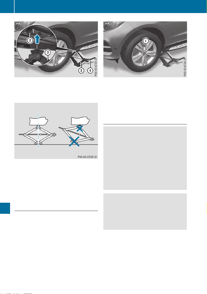
X
Position jack = at jacking point ;.
The alignment bolt on the jack must be inser-
ted into the intended opening on the jacking
point.
X
Make sure the foot of the jack is directly
beneath the jacking point.
X
Turn ratchet wrench ? until jack = sits
completely on jacking point ; and the base
of the jack lies evenly on the ground.
X
Turn ratchet wrench ? until the tire is raised
a maximum of 1.2 in (3 cm) from the ground.
Removing a wheel
!
Do not place wheel bolts in sand or on a dirty
surface. The bolt and wheel hub threads could
otherwise be damaged when you screw them
in.
When mounting/removing wheels, and for as
long as the wheels are removed, avoid applying
any external force on the brake disks. This could
impair the level of comfort when braking.
X
Unscrew the uppermost wheel bolt com-
pletely.
X
Screw alignment bolt : into the thread
instead of the wheel bolt.
X
Unscrew the remaining wheel bolts fully.
X
Remove the wheel.
Mounting a new wheel
G
WARNING
Oiled or greased wheel bolts or damaged
wheel bolts/hub threads can cause the wheel
bolts to come loose. As a result, you could
lose a wheel while driving. There is a risk of
accident.
Never oil or grease wheel bolts. In the event of
damage to the threads, contact a qualified
specialist workshop immediately. Have the
damaged wheel bolts or hub threads
replaced/renewed. Do not continue driving.
G
WARNING
If you tighten the wheel bolts or wheel nuts
when the vehicle is raised, the jack could tip
over. There is a risk of injury.
Only tighten the wheel bolts or wheel nuts
when the vehicle is on the ground.
!
To prevent damage to the paintwork, hold
the wheel securely against the wheel hub
while screwing in the first wheel bolt.
Always pay attention to the instructions and
safety notes in the "Changing a wheel" section
(Y page 371).
Only use wheel bolts that have been designed
for the wheel and the vehicle. For safety rea-
sons, Mercedes-Benz recommends that you
374
Changing a wheel
Wheels and tires
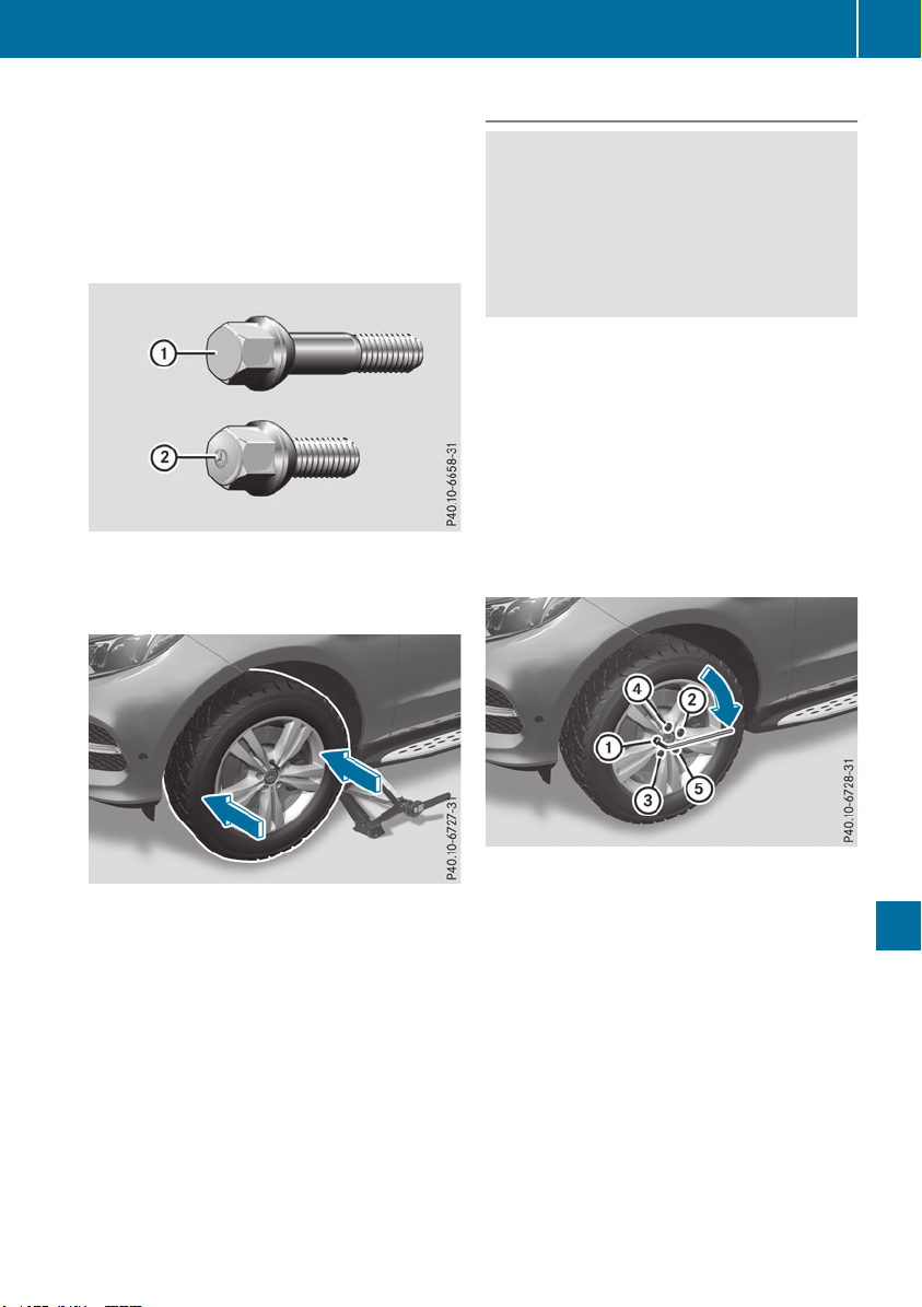
only use wheel bolts which have been approved
for Mercedes-Benz vehicles and the respective
wheel.
!
Always use wheel bolts ; to mount the
"Minispare" emergency spare wheel. Using
other wheel bolts to mount the "Minispare"
emergency spare wheel could damage the
brake system.
:
Wheel bolts for all wheels supplied by the
factory and for the collapsible spare wheel
(Mercedes-AMG GLE 63 4MATIC)
;
Wheel bolts for the collapsible spare wheel
X
Clean the wheel and wheel hub contact sur-
faces.
X
Slide the wheel to be mounted onto the align-
ment bolt and push it on.
X
Tighten the wheel bolts until they are finger-
tight.
X
Unscrew the alignment bolt.
X
Tighten the last wheel bolt until it is finger-
tight.
X
Mercedes-AMG vehicles with a collapsi-
ble spare wheel: inflate the collapsible spare
wheel (Y page 379).
Only then lower the vehicle.
Lowering the vehicle
G
WARNING
The wheels could work loose if the wheel nuts
and bolts are not tightened to the specified
tightening torque. There is a risk of accident.
Have the tightening torque immediately
checked at a qualified specialist workshop
after a wheel is changed.
!
Mercedes-AMG vehicles with a collapsi-
ble spare wheel: before lowering the vehicle,
inflate the collapsible spare wheel with the
tire inflation compressor. The wheel rim could
otherwise be damaged.
X
Place the ratchet wrench onto the hexagon
nut of the jack so that the letters AB are visi-
ble.
X
Turn the ratchet wrench until the vehicle is
once again standing firmly on the ground.
X
Place the jack to one side.
X
Tighten the wheel bolts evenly in a crosswise
pattern in the sequence indicated (: to A).
The tightening torque must be 110 lb-ft
(150 Nm).
X
Turn the jack back to its initial position.
X
Stow the jack and the rest of the tire-change
tool kit in the stowage well under the cargo
compartment floor again.
X
Check the tire pressure of the newly mounted
wheel and adjust it if necessary.
Observe the recommended tire pressure
(Y page 354).
When you are driving with the collapsible spare
wheel mounted, the tire pressure loss warning
system or the tire pressure monitor cannot func-
tion reliably. Only restart the tire pressure loss
warning system or tire pressure monitor when
Changing a wheel
375
Wheels and tires
Z

the defective wheel has been replaced with a
new wheel.
Vehicles with a tire pressure control sys-
tem: all installed wheels must be equipped with
functioning sensors.
Wheel and tire combinations
Information regarding permitted wheel/tire
combinations can be found at an authorized
Mercedes-Benz Center.
!
For safety reasons, Mercedes-Benz recom-
mends that you only use tires and wheels
which have been approved by Mercedes-Benz
specifically for your vehicle.
These tires have been specially adapted for
use with the control systems, such as ABS or
ESP
®
, and are marked as follows:
R
MO = Mercedes-Benz Original
R
MOE = Mercedes-Benz Original Extended
(tires featuring run-flat characteristics)
R
MO1 = Mercedes-Benz Original (only cer-
tain AMG tires)
Mercedes-Benz Original Extended tires may
only be used on wheels that have been spe-
cifically approved by Mercedes-Benz.
Only use tires, wheels or accessories tested
and approved by Mercedes-Benz. Certain
characteristics, e.g. handling, vehicle noise
emissions or fuel consumption, may other-
wise be adversely affected. In addition, when
driving with a load, tire dimension variations
could cause the tires to come into contact
with the bodywork and axle components. This
could result in damage to the tires or the vehi-
cle.
Mercedes-Benz accepts no liability for dam-
age resulting from the use of tires, wheels or
accessories other than those tested and
approved.
Information on tires, wheels and approved
combinations can be obtained from any quali-
fied specialist workshop.
!
Retreaded tires are neither tested nor rec-
ommended by Mercedes-Benz, since previ-
ous damage cannot always be detected on
retreaded tires. As a result, Mercedes-Benz
cannot guarantee vehicle safety if retreaded
tires are mounted. Do not mount used tires if
you have no information about their previous
usage.
The recommended pressures for various oper-
ating conditions can be found:
R
on the Tire and Loading Information placard
on the B-pillar on the driver's side
R
in the tire pressure table in the fuel filler flap
Observe the notes on recommended tire pres-
sures under various operating conditions
(Y page 354).
Check tire pressures regularly, and only when
the tires are cold. Comply with the maintenance
recommendations of the tire manufacturer in
the vehicle document wallet.
Notes on the vehicle equipment – always equip
the vehicle:
R
with tires of the same size on a given axle (left
and right)
R
with the same type of tires at a given time
(summer tires, winter tires, MOExtended
tires)
i
Vehicles equipped with MOExtended tires
are not equipped with a TIREFIT kit at the fac-
tory. It is therefore recommended that you
additionally equip your vehicle with a TIREFIT
kit if you mount tires that do not feature run-
flat properties, e.g. winter tires. A TIREFIT kit
may be obtained from a qualified specialist
workshop.
Emergency spare wheel
Important safety notes
G
WARNING
The wheel or tire size as well as the tire type of
the spare wheel or emergency spare wheel
and the wheel to be replaced may differ.
Mounting an emergency spare wheel may
severely impair the driving characteristics.
There is a risk of an accident.
To avoid hazardous situations:
R
adapt your driving style accordingly and
drive carefully.
R
never mount more than one spare wheel or
emergency spare wheel that differs in size.
376
Emergency spare wheel
Wheels and tires
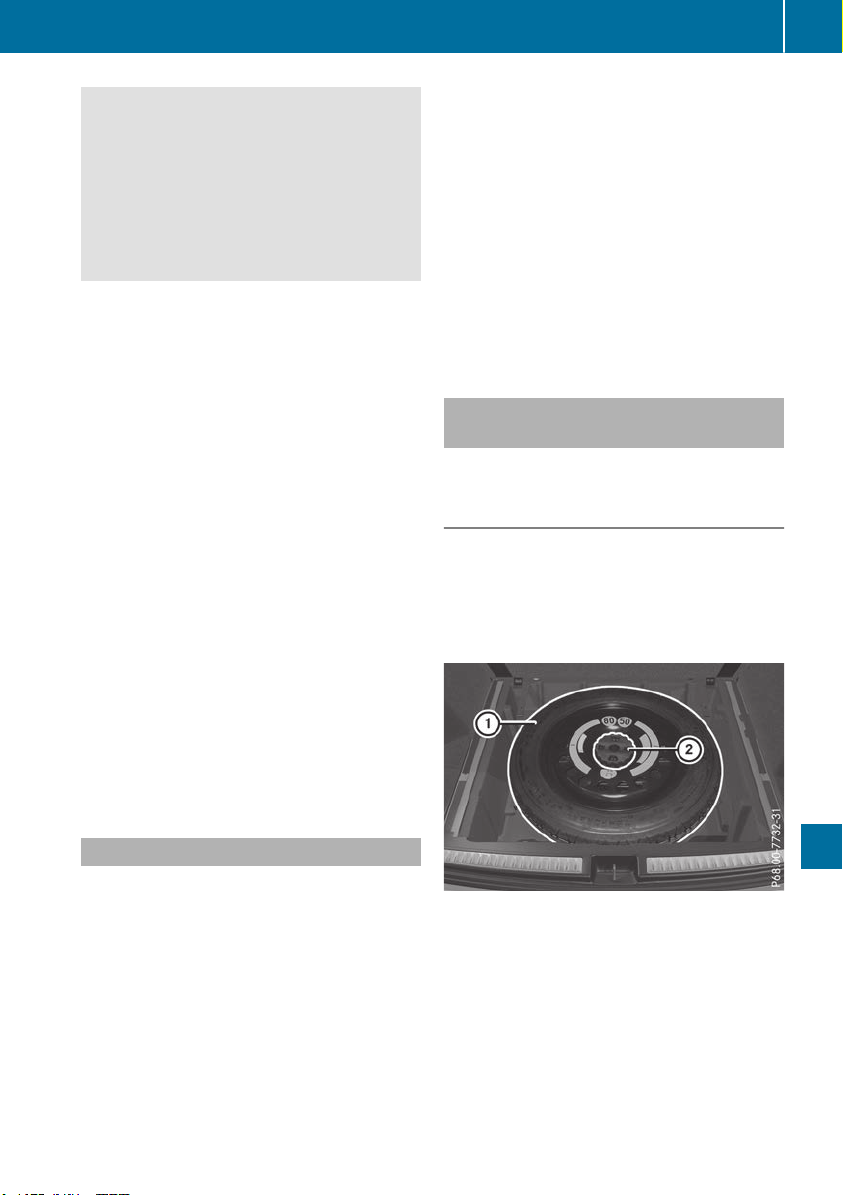
R
only use a spare wheel or emergency spare
wheel of a different size briefly.
R
do not switch ESP
®
off.
R
have a spare wheel or emergency spare
wheel of a different size replaced at the
nearest qualified specialist workshop.
Observe that the wheel and tire dimensions
as well as the tire type must be correct.
!
Mercedes-AMG vehicles with
"Minispare" emergency spare wheel: only
use the "Minispare" emergency spare wheel
on the rear axle. If you mount the
"Minispare" emergency spare wheel on the
front axle, this could result in damage to the
brake system.
If a tire on the front axle is defective, an intact
wheel from the rear axle must first be
replaced with the "Minispare" emergency
spare wheel. The damaged wheel on the front
axle can then be replaced by the undamaged
wheel from the rear axle.
Make sure to note the placard on the
"Minispare" emergency spare wheel.
When using an emergency spare wheel or spare
wheel of a different size, you must not exceed
the maximum speed of 50 mph (80 km/h).
You should regularly check the pressure of the
emergency spare wheel, particularly prior to
long trips, and correct the pressure as neces-
sary (Y page 354). The value on the wheel is
valid.
Snow chains must not be mounted on emer-
gency spare wheels.
General notes
Information regarding permitted emergency
spare wheels can be found at an authorized
Mercedes-Benz Center.
Mounting the emergency spare wheel is descri-
bed under "Mounting a wheel" (Y page 372).
An emergency spare wheel may also be moun-
ted against the direction of rotation. Observe
the time restriction on use as well as the speed
limitation specified on the emergency spare
wheel.
Replace the tires after six years at the latest,
regardless of wear. This also applies to the
emergency spare wheel.
When you are driving with the collapsible spare
wheel mounted, the tire pressure loss warning
system or the tire pressure monitor cannot func-
tion reliably. Only restart the tire pressure loss
warning system or tire pressure monitor when
the defective wheel has been replaced with a
new wheel.
Vehicles with tire pressure monitor: after
mounting an emergency spare wheel, the sys-
tem may still display the tire pressure of the
removed wheel for a few minutes. The value dis-
played for the mounted emergency spare wheel
is not the same as the current tire pressure of
the emergency spare wheel.
Removing/stowing the emergency
spare wheel
Vehicles with a "Minispare" emergency
spare wheel under the cargo compart-
ment floor
Always observe the instructions and safety
notes in the "Mounting a wheel" section
(Y page 372).
The "Minispare" emergency spare wheel can be
found in the stowage well under the cargo com-
partment floor.
Removing the emergency spare wheel
X
Lift the cargo compartment floor upwards
(Y page 303).
X
Vehicle without a lockable cargo compart-
ment floor: turn emergency spare wheel
retainer ; counter-clockwise and remove it.
X
Remove "Minispare" emergency spare
wheel :.
Emergency spare wheel
377
Wheels and tires
Z
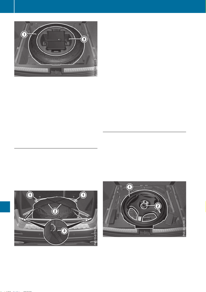
X
Vehicle with a lockable cargo compart-
ment floor: remove the contents of stowage
tray =.
X
Turn the central retaining screw in stowage
tray = and in "Minispare" emergency spare
wheel : counter-clockwise and remove it.
X
Remove stowage well =.
X
Remove "Minispare" emergency spare
wheel :.
Vehicles with a "Minispare" emergency
spare wheel in the emergency spare
wheel bag
Always observe the instructions and safety
notes in the "Mounting a wheel" section
(Y page 372).
On vehicles with a Bang & Olufsen sound sys-
tem, the "Minispare" emergency spare wheel is
packed in an emergency spare wheel bag. The
emergency spare wheel bag is secured to the
cargo tie-down rings in the cargo compartment.
Removing the emergency spare wheel
X
Detach the fastening straps ;.
X
Unhook retaining spring hooks : and = of
fastening straps ; from the cargo tie-down
rings.
X
Remove the emergency spare wheel bag with
the "Minispare" emergency spare wheel.
X
Open the emergency spare wheel bag and
remove the "Minispare" emergency spare
wheel.
Stowing the emergency spare wheel
X
Place the "Minispare" emergency spare wheel
into the emergency spare wheel bag and
close the emergency spare wheel bag.
X
Place the emergency spare wheel bag with
the "Minispare" emergency spare wheel into
the cargo compartment with the carrying
strap at the back.
X
Hook retaining spring hooks : and = of
fastening straps ; into the cargo tie-down
rings.
X
Tighten fastening straps ;.
Mercedes-AMG vehicles with a collaps-
ible spare wheel under the cargo com-
partment floor
!
Only place the collapsible spare wheel in the
vehicle when it is dry. Otherwise, moisture
may get into the vehicle.
Always observe the instructions and safety
notes in the "Mounting a wheel" section
(Y page 372).
The collapsible spare wheel can be found in the
stowage well under the cargo compartment
floor.
Removing the emergency spare wheel
X
Lift the cargo compartment floor upwards
(Y page 303).
X
Unscrew retaining screw ; counter-clock-
wise.
X
Remove collapsible spare wheel : from the
spare wheel well.
378
Emergency spare wheel
Wheels and tires
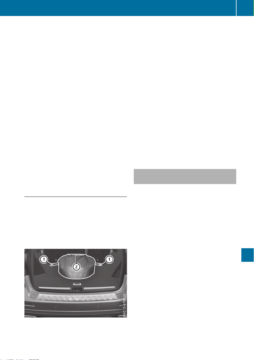
Inflating the collapsible spare wheel
(Y page 379).
Take the following steps to stow a used collaps-
ible spare wheel. Otherwise, it will not fit into the
spare wheel well. Mercedes-Benz recommends
that you have this work performed at a qualified
specialist workshop, e.g. at an authorized
Mercedes-Benz Center.
Stowing the emergency spare wheel
X
Unscrew the valve cap from the valve.
X
If possible, unscrew the valve insert from the
valve and release the air.
i
Fully deflating the tires can take a few
minutes.
X
Screw the valve insert back into the valve.
X
Screw the valve cap back on.
X
Lay collapsible spare wheel : in the emer-
gency spare wheel well.
X
Screw in retaining screw ; clockwise in the
collapsible spare wheel to the stop.
X
Swing the cargo compartment floor down
(Y page 303).
Mercedes-AMG vehicles with a collaps-
ible spare wheel in the emergency
spare wheel bag
Always observe the instructions and safety
notes in the "Mounting a wheel" section
(Y page 372).
On Mercedes-AMG vehicles with a Bang & Oluf-
sen sound system, the collapsible spare wheel is
packed in an emergency spare wheel bag. The
emergency spare wheel bag is secured to the
cargo tie-down rings in the cargo compartment.
Removing the emergency spare wheel
X
Unhook retaining spring hooks : of fasten-
ing strap ; from the cargo tie-down rings.
X
Remove the emergency spare wheel bag with
the emergency collapsible spare wheel.
X
Open the bag and remove the emergency col-
lapsible spare wheel.
Inflating the collapsible spare wheel
(Y page 379).
Stowing the emergency spare wheel
X
Place the collapsible spare wheel into the
emergency spare wheel bag and close the
emergency spare wheel bag.
X
Place the emergency spare wheel bag with
the collapsible spare wheel into the cargo
compartment with the carrying strap at the
back.
X
Hook retaining spring hooks : of fastening
strap ; into the cargo tie-down rings.
X
Tighten fastening strap ;.
Inflating the collapsible spare wheel
(Mercedes-AMG GLE 63 4MATIC)
!
Inflate the collapsible spare wheel using the
tire inflation compressor before lowering the
vehicle. The wheel rim could otherwise be
damaged.
!
Do not operate the tire inflation compressor
for longer than eight minutes at a time without
a break. It may otherwise overheat.
The tire inflation compressor can be operated
again once it has cooled down.
Comply with the manufacturer's safety instruc-
tions on the tire inflation compressor label and
on the tire sealant bottle.
X
Mount the collapsible spare wheel as descri-
bed (Y page 372).
The collapsible spare wheel must be mounted
before it is inflated.
X
Remove the tire inflation compressor from
the stowage space under the cargo compart-
ment floor (Y page 335).
Emergency spare wheel
379
Wheels and tires
Z
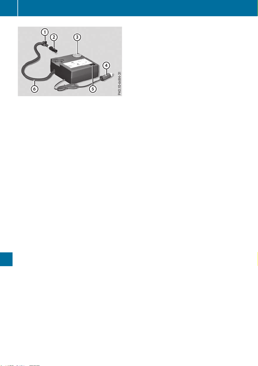
X
Pull connector ? and hose B out of the
housing.
X
Remove the cap from the valve on the col-
lapsible spare wheel.
X
Screw union nut ; of hose B onto the valve.
X
Make sure on/off switch A of the tire infla-
tion compressor is set to 0.
X
Insert connector ? into a socket in your vehi-
cle.
Cigarette lighter socket: (Y page 307)
12 V sockets: (Y page 308)
Observe the notes on the cigarette lighter
(Y page 307). Observe the notes on sockets
(Y page 308).
X
Turn the SmartKey to position 1 in the igni-
tion lock (Y page 135).
X
Press on and off switch A on the tire inflation
compressor to I.
The tire inflation compressor is switched on.
The tire is inflated. The tire pressure is shown
on pressure gauge =.
X
Inflate the tire to the specified tire pressure.
The specified tire pressure is printed on the
yellow label of the emergency spare wheel.
X
When the specified tire pressure has been
reached, press on and off switch A on the
tire inflation compressor to 0.
The tire inflation compressor is switched off.
X
Turn the SmartKey to position u in the igni-
tion lock.
X
If the tire pressure is higher than the specified
pressure, press pressure release valve but-
ton : until the correct tire pressure has been
reached.
X
Unscrew union nut ; on hose B from the
valve.
X
Screw the cap onto the valve of the collapsi-
ble spare wheel again.
X
Stow connector ? and hose B in the lower
section of the tire inflation compressor.
X
Stow the tire inflation compressor in the vehi-
cle.
380
Emergency spare wheel
Wheels and tires
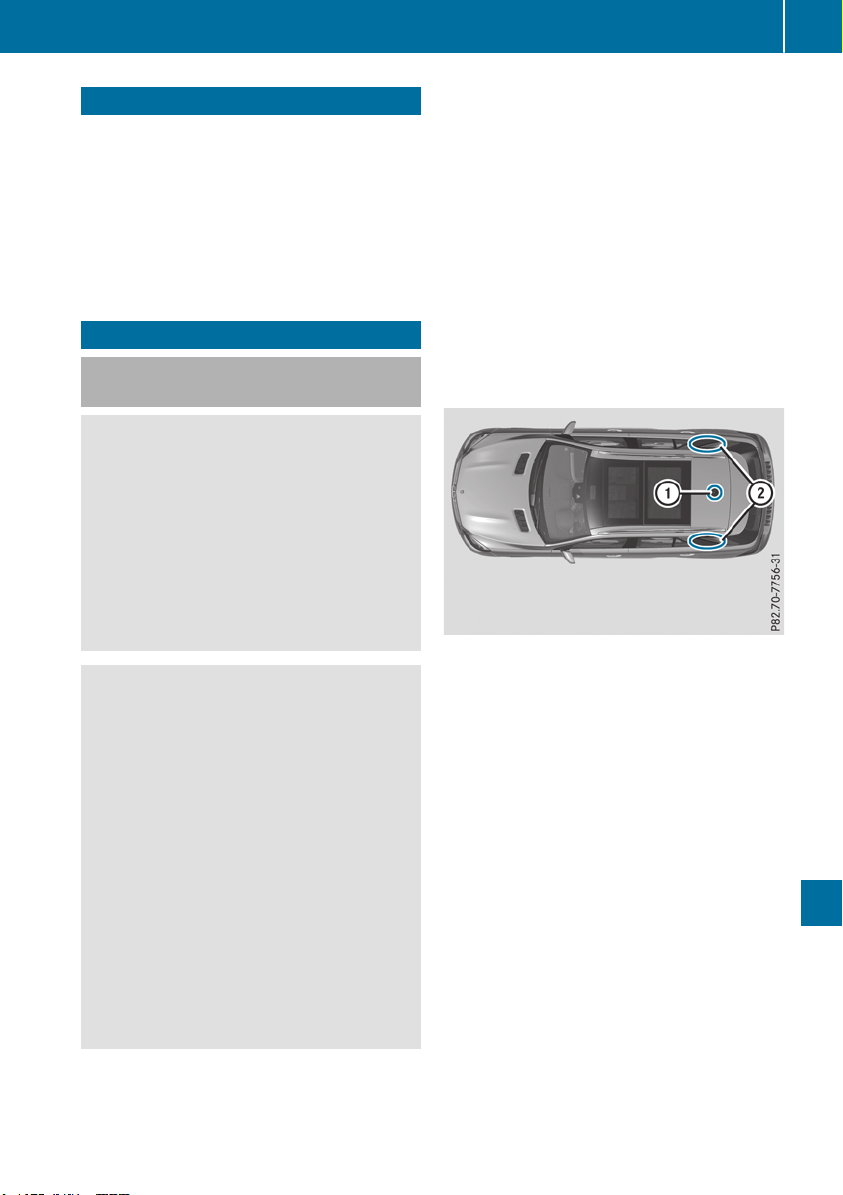
Information regarding technical data
Plug-in hybrid: be sure to read the separate
Operator's Manual. Otherwise, you may not rec-
ognize dangers.
i
The data stated here specifically refers to a
vehicle with standard equipment. Consult an
authorized Mercedes-Benz Center for the
data for all vehicle variants and trim levels.
Vehicle electronics
Installing two-way radios and mobile
phones (RF transmitters)
G
WARNING
The electromagnetic radiation from two-way
radios can interfere with the vehicle electron-
ics if two-way radios are manipulated or ret-
rofitted incorrectly. This could jeopardize the
operating safety of the vehicle. There is a risk
of an accident.
You should have all work on electrical and
electronic components carried out at a quali-
fied specialist workshop.
G
WARNING
If you incorrectly operate two-way radios in
the vehicle, the electromagnetic radiation
may interfere with the vehicle electronics, for
example if:
R
the two-way radio is not connected to an
exterior antenna
R
the exterior antenna is not correctly moun-
ted or is not low-reflection
This could jeopardize the operating safety of
the vehicle. There is a risk of an accident.
Have the low-reflection exterior antenna
installed at a qualified specialist workshop.
Always connect two-way radios to the low-
reflection exterior antenna when operating in
the vehicle.
!
The operating permit may be invalidated if
the instructions for installation and use of
two-way radios are not observed.
In particular, the following conditions must be
complied with:
R
only approved wavebands may be used
R
observe the maximum permissible output
in these wavebands
R
only approved antenna positions may be
used
Excessive levels of electromagnetic radiation
may cause damage to your health and the health
of others. Using an exterior antenna takes into
account current scientific discussions relating
to the possible health hazards that may result
from electromagnetic fields.
The following antenna positions may be used for
the correct installation of two-way radios:
Approved antenna positions
:
Rear roof area
;
Rear fender
i
On the rear fenders, it is recommended to
position the antenna on the side of the vehicle
closest to the center of the road.
Use Technical Specification ISO/TS 21609
(Road Vehicles – "EMC guidelines for installa-
tion of aftermarket radio frequency transmitting
equipment") when installing wireless devices.
Observe the legal requirements for accessory
parts.
If your vehicle has installations for two-way radio
equipment, use the power supply or antenna
connections intended for use with the basic wir-
ing. Be sure to observe the manufacturer's Sup-
plement when installing.
Deviations with respect to frequency bands,
maximum transmission outputs or antenna
positions must be approved by Mercedes-Benz.
Vehicle electronics
381
Technical data
Z
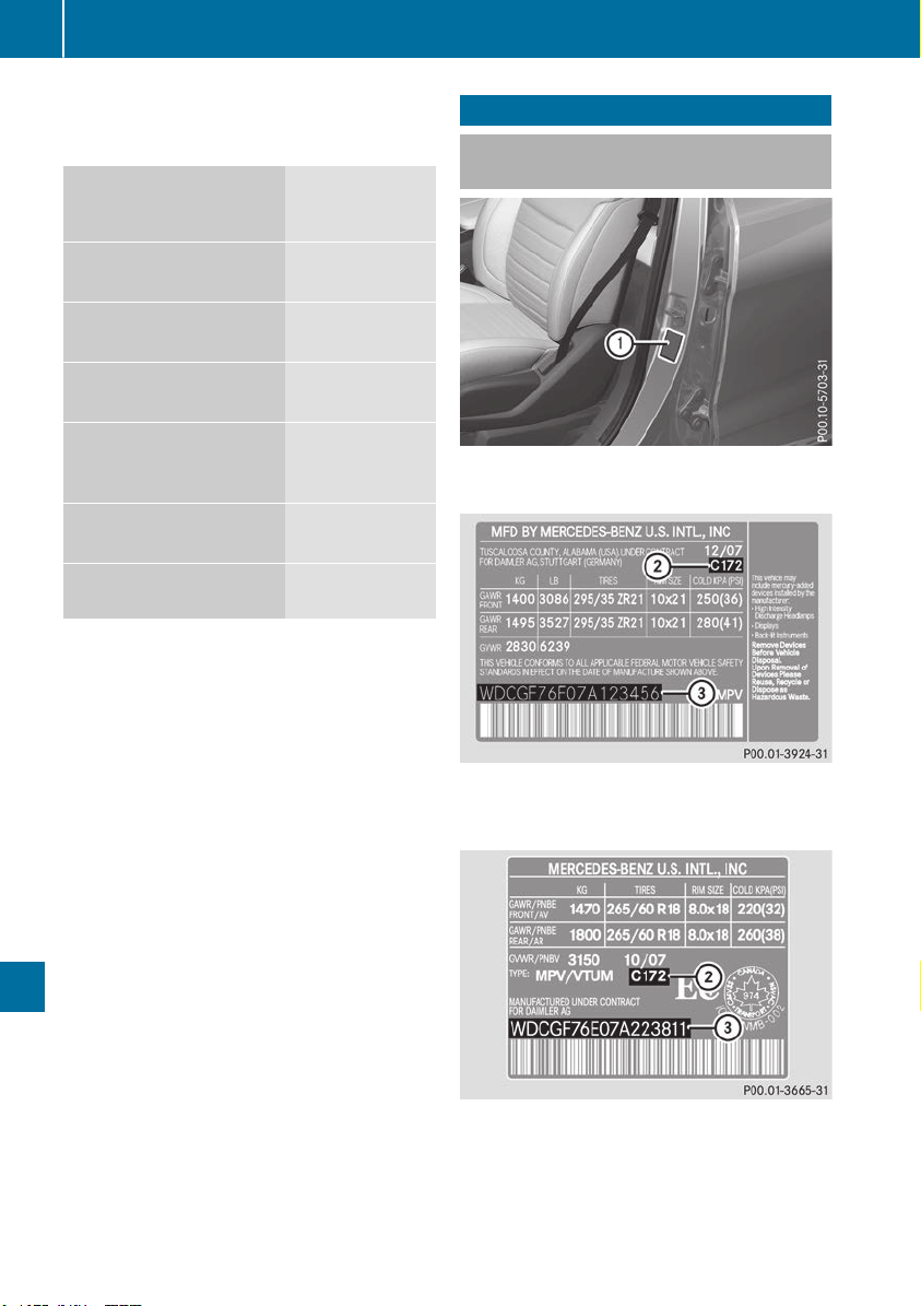
The maximum transmission output (PEAK) at the
base of the antenna must not exceed the fol-
lowing values:
Frequency band Maximum
transmission
output
Short wave
3 - 54 MHz
100 W
4 m waveband
74 - 88 MHz
30 W
2 m waveband
144 - 174 MHz
50 W
Trunked radio system/
Tetra
380 - 460 MHz
10 W
70 cm waveband
400 - 460 MHz
35 W
Mobile communications
(2G/3G/4G)
10 W
The following can be used in the vehicle without
restrictions:
R
Two-way radios with a maximum transmission
output of up to 100 mW
R
Two-way radios with transmitter frequencies
in the 380 - 410 MHz waveband and a maxi-
mum transmission output of up to 2 W
(trunked radio/Tetra)
R
Mobile phones (2G/3G/4G)
There are no restrictions when positioning the
antenna on the outside of the vehicle for the
following wavebands:
R
Trunked radio system/Tetra
R
70 cm waveband
R
2G/3G/4G
Identification plates
Vehicle identification plate with vehi-
cle identification number (VIN)
X
Open the driver's door.
You will see vehicle identification plate :.
Example: vehicle identification plate (USA only)
;
Paint code
=
VIN
Example: vehicle identification plate (Canada only)
;
Paint code
=
VIN
i
The data shown on the vehicle identification
plate is used only as an example. This data is
different for every vehicle and can deviate
382
Identification plates
Technical data
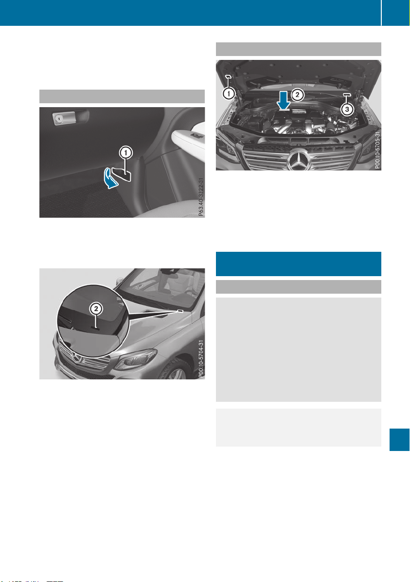
from the data shown here. You can find the
data applicable to your vehicle on the vehicle
identification plate.
Vehicle identification number (VIN)
X
Open the front right-hand door.
X
Open cover : in the direction of the arrow
and remove it.
The VIN can be seen.
The VIN can also be found in the following loca-
tions:
R
on the lower edge of windshield ;
R
on the vehicle identification plate
(Y page 382)
Engine number
:
Emission control information plate, includ-
ing the certification of both federal and Cali-
fornian emissions standards
;
Engine number (stamped into the crank-
case)
=
VIN (on the lower edge of the windshield)
Service products and filling capaci-
ties
Important safety notes
G
WARNING
Service products may be poisonous and haz-
ardous to health. There is a risk of injury.
Comply with instructions on the use, storage
and disposal of service products on the labels
of the respective original containers. Always
store service products sealed in their original
containers. Always keep service products out
of the reach of children.
H
Environmental note
Dispose of service products in an environ-
mentally responsible manner.
Service products include the following:
R
Fuels
R
Exhaust gas aftertreatment additives, e.g.
DEF
R
Lubricants (e.g. engine oil, transmission oil)
R
Coolant
R
Brake fluid
R
Windshield washer fluid
R
Climate control system refrigerant
Service products and filling capacities
383
Technical data
Z

Components and service products must match.
You should therefore only use products that
have been tested and approved by Mercedes-
Benz.
You can identify service products approved by
Mercedes-Benz by the following inscriptions on
the container:
R
MB-Freigabe (e.g. MB-Freigabe 229.51)
R
MB-Approval (e.g. MB-Approval 229.51)
Other designations or recommendations indi-
cate a level of quality or a specification in
accordance with an MB Sheet Number (e.g. MB
229.5). They have not necessarily been
approved by Mercedes-Benz.
Other identifications, for example:
R
0 W-30
R
5 W-30
R
5 W-40
Fuel
Important safety notes
G
WARNING
Fuel is highly flammable. Risk of fire and
explosion by improper handling of fuel.
You must avoid fire, open flames, smoking
and creating sparks. Switch off the ignition
before refueling and, if present, switch off the
auxiliary heating.
G
WARNING
Fuel is poisonous and hazardous to health.
There is a risk of injury.
You must make sure that fuel does not come
into contact with your skin, eyes or clothing
and that it is not swallowed. Do not inhale fuel
vapors. Keep fuel away from children.
If you or others come into contact with fuel,
observe the following:
R
Wash away fuel from skin immediately
using soap and water.
R
If fuel comes into contact with your eyes,
immediately rinse them thoroughly with
clean water. Seek medical assistance with-
out delay.
R
If fuel is swallowed, seek medical assis-
tance without delay. Do not induce vomit-
ing.
R
Immediately change out of clothing which
has come into contact with fuel.
Tank capacity
Model Total capa-
city
GLE 550 e 4MATIC
21.1 US gal
(80.0 l)
All other models
24.6 US gal
(93.0 l)
Model Of which
reserve
Mercedes-AMG GLE 43
4MATIC
Approx.
3.2 US gal
(12.0 l)
Mercedes‑AMG vehicles
Approx.
3.7 US gal
(14.0 l)
All other models
Approx.
3.2 US gal
(12.0 l)
Gasoline
Fuel grade
!
Do not use diesel to refuel vehicles with a
gasoline engine. Do not switch on the ignition
if you accidentally refuel with the wrong fuel.
Otherwise, the fuel will enter the fuel system.
Even small amounts of the wrong fuel could
result in damage to the fuel system and the
engine. Notify a qualified specialist workshop
and have the fuel tank and fuel lines drained
completely.
!
Only refuel using unleaded premium grade
gasoline with at least 91 AKI/95 RON.
i
E10 fuel contains up to 10% bioethanol.
Your vehicle is E10-compatible. You can
refuel your vehicle using E10 fuel.
!
Only use the fuel recommended. Operating
the vehicle with other fuels can lead to dam-
384
Service products and filling capacities
Technical data

age to the fuel system, engine and exhaust
system.
!
Do not use the following:
R
Gasoline with more than 10% ethanol
R
E100 (100% ethanol)
R
Gasoline with methanol
R
M100 (100% methanol)
R
Gasoline with metalliferous additives
R
Diesel
Do not mix such fuels with the fuel recom-
mended for your vehicle.
!
To ensure the longevity and full perform-
ance of the engine, only premium-grade
unleaded gasoline must be used.
If standard unleaded gasoline is unavailable
and you have to refuel with unleaded gasoline
of a lower grade, observe the following pre-
cautions:
R
Only fill the fuel tank to half full with regular
unleaded gasoline and fill the rest with pre-
mium-grade unleaded gasoline as soon as
possible.
R
Do not drive at the maximum speed.
R
Avoid sudden acceleration and engine
speeds over 3,000 rpm.
i
For more information, please contact a
qualified specialist workshop or visit
http://www.mbusa.com (USA only).
As a temporary measure, if the recommended
fuel is not available, you may also use regular
unleaded gasoline with an octane rating of
87 AKI/91 RON. This may reduce engine per-
formance and increase fuel consumption. Avoid
driving at full throttle and sudden acceleration.
Never refuel using gasoline with a lower AKI.
Information on refueling (Y page 151).
Additives
!
Operating the engine with fuel additives
added later can lead to engine failure. Do not
mix fuel additives with fuel. This does not
include additives for the removal and preven-
tion of residue buildup. gasoline must only be
mixed with additives recommended by
Mercedes-Benz. Comply with the instructions
for use on the product label. More information
about recommended additives can be
obtained from any authorized Mercedes-Benz
Center.
Mercedes-Benz recommends that you use bran-
ded fuels that have additives.
The fuel quality available in some countries may
not be sufficient. Residue could build up in the
fuel injection system as a result. In such cases,
and in consultation with an authorized
Mercedes-Benz Center, the fuel may be mixed
with the cleaning additive recommended by
Mercedes-Benz. You must observe the notes
and mixing ratios specified on the container.
Diesel
Fuel grade
G
WARNING
If you mix diesel fuel with gasoline, the flash
point is lower than that of pure diesel fuel.
When the engine is running, exhaust system
components could overheat without being
noticed. There is a risk of fire.
Never refuel with gasoline. Never mix gasoline
with diesel fuel.
!
Only use Ultra Low Sulfur Diesel (ULSD),
otherwise it may lead to increased wear and
damage to the fuel system, engine and
exhaust system.
!
Do not use the following:
R
gasoline
R
diesel with a bio-diesel content greater
than 5% (e.g. B20)
R
bio-diesel
R
vegetable oil
R
paraffin
R
kerosene
R
marine diesel
R
heating oil
Do not mix such fuels with diesel fuel and do
not use any special additives. Otherwise,
engine damage may occur.
!
In countries outside USA and Canada, only
use sulfur-free diesel with a sulfur content
under 50 ppm. Otherwise, the emission con-
trol system could be damaged.
Low outside temperatures
i
Diesel fuel with improved cold flow proper-
ties is available during the winter months.
Further information about fuel properties can
Service products and filling capacities
385
Technical data
Z

be obtained from oil companies, e.g. at gas
stations.
Flexible Fuel vehicles
Important safety notes
G
WARNING
Fuel is highly flammable. Risk of fire and
explosion by improper handling of fuel.
You must avoid fire, open flames, smoking
and creating sparks. Switch off the ignition
before refueling and, if present, switch off the
auxiliary heating.
G
WARNING
Fuel is poisonous and hazardous to health.
There is a risk of injury.
You must make sure that fuel does not come
into contact with your skin, eyes or clothing
and that it is not swallowed. Do not inhale fuel
vapors. Keep fuel away from children.
If you or others come into contact with fuel,
observe the following:
R
Wash away fuel from skin immediately
using soap and water.
R
If fuel comes into contact with your eyes,
immediately rinse them thoroughly with
clean water. Seek medical assistance with-
out delay.
R
If fuel is swallowed, seek medical assis-
tance without delay. Do not induce vomit-
ing.
R
Immediately change out of clothing which
has come into contact with fuel.
Flexible Fuel vehicles can be refueled with the
following fuel types:
R
premium-grade unleaded gasoline
R
E85 fuel
R
a mixture of E85 fuel and premium-grade
unleaded gasoline
i
Flexible Fuel vehicles can be recognized by
the Ethanol up to E85 sticker on the inside of
the fuel filler flap.
Fuel consumption
The energy content of E85 fuel is less than that
of the same amount of premium-grade gasoline.
The amount of fuel consumed when operating
the vehicle with E85 fuel is therefore higher than
with premium-grade gasoline.
Maintenance
Inform your authorized Mercedes-Benz Center
that you are operating or have operated the
vehicle with E85 fuel.
Low outside temperatures
If the outside temperature is below 32 ‡(0 †),
the starting procedure can take noticeably lon-
ger when operating with E85 fuel.
E85 fuel is not suitable for use at outside tem-
peratures under -4 ‡ (-20 †).
DEF
Important safety notes
Comply with the important safety notes for ser-
vice products when handling DEF (Y page 383).
DEF is a water-soluble fluid for the exhaust gas
aftertreatment of diesel engines. It is:
R
not poisonous
R
colorless and odorless
R
not flammable
When you open the DEF container, small
amounts of ammonia vapor may be released.
Ammonia vapors have a pungent odor and are
particularly irritating to the skin, to mucous
membranes and to the eyes. You may experi-
ence a burning sensation in your eyes, nose and
throat. Coughing and watering of the eyes are
possible.
Do not inhale ammonia vapors. Fill the DEF tank
only in well-ventilated areas.
Low outside temperatures
DEF freezes at a temperature of approximately
12 ‡(-11 †). The vehicle is delivered from the
factory equipped with a DEF preheating system.
Winter operation can thus be guaranteed even
at temperatures below 12 ‡ (-11 †).
386
Service products and filling capacities
Technical data
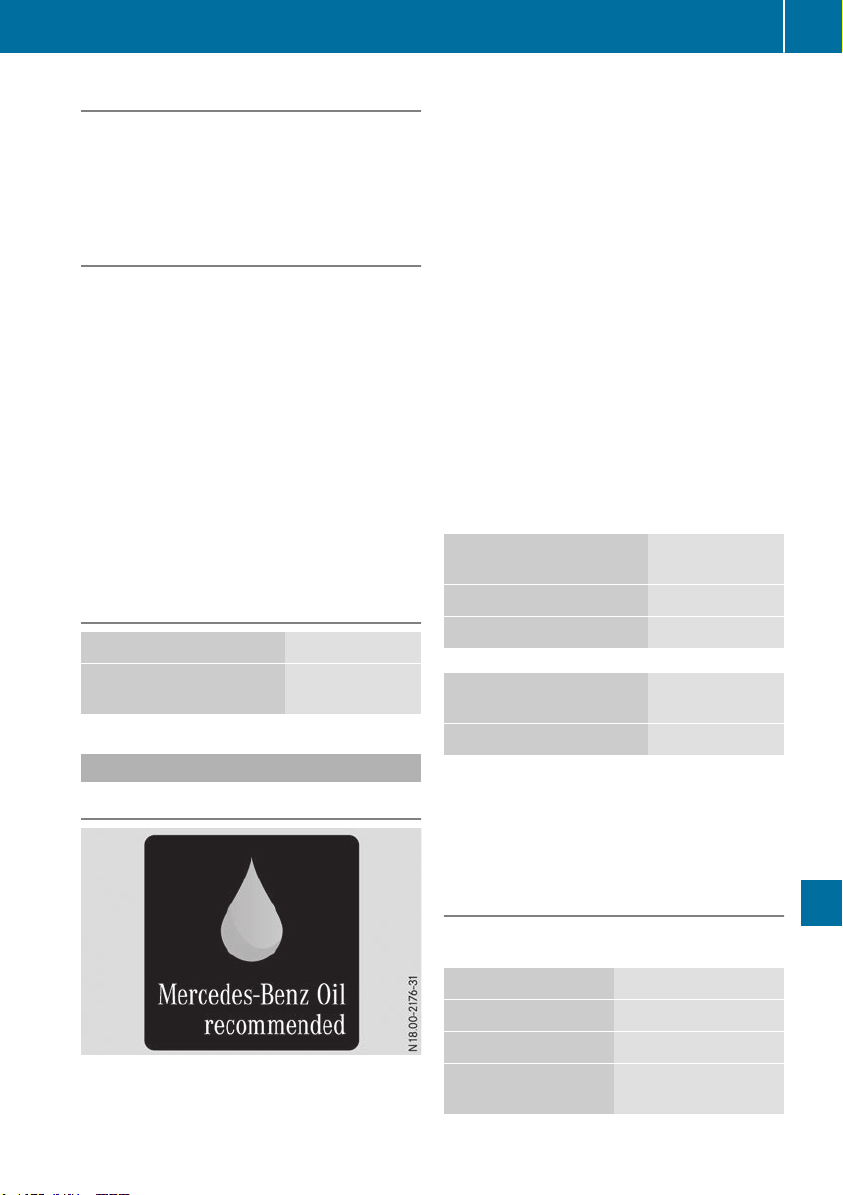
Additives
!
Only use DEF in accordance with ISO
22241. Do not use additives with DEF and do
not dilute DEF with water. This may destroy
the BlueTEC exhaust gas aftertreatment sys-
tem.
Purity
!
Impurities in DEF (e.g. due to other service
products, cleaning agents or dust) lead to:
R
increased emission values
R
damage to the catalytic converter
R
engine damage
R
malfunctions in the BlueTEC exhaust gas
aftertreatment system
Assuring the purity of DEF is particularly impor-
tant with respect to avoiding malfunctions in the
BlueTEC exhaust gas aftertreatment system.
If DEF is pumped out of the DEF tank, e.g. during
repair work, it must not be returned to the tank.
The purity of the fluid can no longer be guaran-
teed.
Filling capacities
Model Total capacity
All models
8.5 US gal
(32.0 l)
Engine oil
General notes
!
Do not use engine oil or an oil filter with
specifications deviating from those expressly
required for the prescribed service intervals.
Do not change the engine oil or oil filter in
order to set replacement intervals longer than
those prescribed. This could otherwise cause
damage to the engine or exhaust gas after-
treatment.
Follow the instructions on the service interval
display for changing the engine oil. This could
otherwise cause damage to the engine or
exhaust gas aftertreatment.
When handling engine oil, observe the important
safety notes on service products (Y page 383).
The engine oils are matched to the performance
of Mercedes-Benz engines and service intervals.
You should therefore only use engine oils and oil
filters that are approved for vehicles with main-
tenance systems.
For a list of approved engine oils and oil filters,
consult an authorized Mercedes-Benz Center.
Alternatively, visit the website
http://bevo.mercedes-benz.com.
The table shows which engine oils have been
approved for your vehicle.
Gasoline engines MB-Freigabe or
MB-Approval
All models
229.5, 229.6
Mercedes‑AMG vehicles
229.5
Diesel engines MB-Freigabe or
MB-Approval
All models
229.52
Mercedes-AMG vehicles: only use SAE 0W-40
or SAE 5W-40 engine oils.
i
MB approval is indicated on the oil contain-
ers.
Filling capacities
The following values refer to an engine oil
change, including the oil filter.
Model Capacity
GLE 300 d 4MATIC
6.9 US qt (6.5 l)
GLE 350 d 4MATIC
8.5 US qt (8.0 l)
Mercedes-AMG
GLE 43 4MATIC
7.4 US qt (7.0 l)
Service products and filling capacities
387
Technical data
Z

Model Capacity
GLE 550 4MATIC
Mercedes-AMG
GLE 63 4MATIC
Mercedes-AMG
GLE 63 S 4MATIC
9.0 US qt (8.5 l)
All other models
7.4 US qt (7.0 l)
Additives
!
Do not use any additives in the engine oil.
This could damage the engine.
Brake fluid
G
WARNING
The brake fluid constantly absorbs moisture
from the air. This lowers the boiling point of
the brake fluid. If the boiling point of the brake
fluid is too low, vapor pockets may form in the
brake system when the brakes are applied
hard. This would impair braking efficiency.
There is a risk of an accident.
You should have the brake fluid renewed at
the specified intervals.
Comply with the important safety notes for ser-
vice products when handling brake fluid
(Y page 383).
Use only brake fluid approved for Mercedes-
Benz according to MB-Freigabeor MB-Approval
331.0.
Information about approved brake fluid can be
obtained at any qualified specialist workshop or
on the Internet at
http://bevo.mercedes-benz.com.
i
Have the brake fluid regularly replaced at a
qualified specialist workshop in accordance
with the replacement intervals and the
replacement confirmed in the service report.
Coolant
Important safety notes
G
WARNING
If antifreeze comes into contact with hot com-
ponents in the engine compartment, it may
ignite. There is a risk of fire and injury.
Let the engine cool down before you add anti-
freeze. Make sure that antifreeze is not spilled
next to the filler neck. Thoroughly clean the
antifreeze from components before starting
the engine.
!
Only add coolant that has been premixed
with the desired antifreeze protection. You
could otherwise damage the engine.
Further information on coolants can be found
in the Mercedes-Benz Specifications for Ser-
vice Products, MB BeVo 310.1, e.g. on the
Internet at
http://bevo.mercedes-benz.com. Or con-
tact a qualified specialist workshop.
!
Always use a suitable coolant mixture, even
in countries where high temperatures prevail.
Otherwise, the engine cooling system is not
sufficiently protected from corrosion and
overheating.
i
Have the coolant regularly replaced at a
qualified specialist workshop and the replace-
ment confirmed in the service report.
Comply with the important safety notes for ser-
vice products when handling coolant
(Y page 383).
The coolant is a mixture of water and anti-
freeze/corrosion inhibitor. It is responsible for
the following:
R
anti-corrosion protection
R
antifreeze protection
R
raising the boiling point
If the coolant has antifreeze protection down to
-35 ‡ (-37 †), the boiling point of the coolant
during operation is approximately 266 ‡
(130 †).
388
Service products and filling capacities
Technical data

The antifreeze concentrate/corrosion inhibitor
concentration in the engine cooling system
should:
R
be at least 50%. This will protect the engine
cooling system against freezing down to
approximately -35 ‡ (-37 †).
R
not exceed 55% (antifreeze protection down
to -49 ‡[-45 †]). Otherwise, heat will not be
dissipated as effectively.
Mercedes-Benz recommends an antifreeze/
corrosion inhibitor concentrate in accordance
with MB Specifications for Service Products
310.1.
i
When the vehicle is first delivered, it is filled
with a coolant mixture that ensures adequate
antifreeze and anti-corrosion protection.
i
The coolant is checked at specified intervals
at a qualified specialist workshop.
Filling capacities
Missing values were not available at time of
going to print.
Model Capacity
Mercedes‑AMG
vehicles
Approx. 11.9 US qt
(11.3 l)
GLE 300 d 4MATIC
Approx. 10.7 US qt
(10.1 l)
GLE 350
Approx. 11.1 US qt
(10.5 l)
GLE 350 4MATIC
Approx. 11.1 US qt
(10.5 l)
GLE 350 d 4MATIC
Approx. 12.2 US qt
(11.5 l)
GLE 400 4MATIC
Approx. 10.3 US qt
(9.7 l)
Mercedes-AMG
GLE 43 4MATIC
Approx. 10.3 US qt
(9.7 l)
GLE 550 4MATIC
All other models
Approx. 10.3 US qt
(9.7 l)
Windshield washer system
Important safety notes
G
WARNING
Windshield washer concentrate could ignite if
it comes into contact with hot engine compo-
nents or the exhaust system. There is a risk of
fire and injury.
Make sure that no windshield washer con-
centrate is spilled next to the filler neck.
!
Only MB SummerFit and MB WinterFit
washer fluid should be mixed together. The
spray nozzles may otherwise become
blocked.
Do not use distilled or de-ionized water. Other-
wise, the level sensor may give a false reading.
When handling washer fluid, observe the impor-
tant safety notes on service products
(Y page 383).
At temperatures above freezing:
X
Fill the washer fluid reservoir with a mixture of
water and windshield washer fluid, e.g. MB
SummerFit.
Add 1 part MB SummerFit to 100 parts water.
At temperatures below freezing:
X
Fill the washer fluid reservoir with a mixture of
water and washer fluid, e.g. MB WinterFit.
For the correct mixing ratio refer to the infor-
mation on the antifreeze reservoir.
i
Add windshield washer fluid, e.g. MB Sum-
merFit or MB WinterFit, to the washer fluid all
year round.
Climate control system refrigerant
Important safety notes
The climate control system of your vehicle is fil-
led with refrigerant R‑134a.
The instruction label regarding the refrigerant
type used can be found on the radiator cross
member.
!
Only the refrigerant R‑134a and the PAG oil
approved by Mercedes-Benz may be used.
The approved PAG oil may not be mixed with
any other PAG oil that is not approved for
Service products and filling capacities
389
Technical data
Z
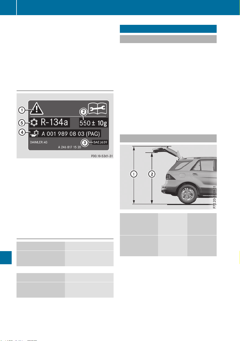
R-134a refrigerant. Otherwise, the climate
control system may be damaged.
Service work, such as refilling with refrigerant or
replacing component parts, may only be carried
out by a qualified specialist workshop. All appli-
cable regulations, as well as SAE standard J639,
must be adhered to.
Always have work on the climate control system
carried out at a qualified specialist workshop.
Refrigerant instruction label
Example: refrigerant instruction label
:
Warning symbol
;
Refrigerant filling capacity
=
Applicable standards
?
PAG oil part number
A
Type of refrigerant
Warning symbol : advises you about:
R
Possible dangers
R
Having service work carried out at a qualified
specialist workshop
Filling capacities
Refrigerant Capacity
All models
37.0 ± 0.4 oz
(1050 ± 10 g)
PAG oil Capacity
All models
3.9 ± 0.4 oz
(110 ± 10 g)
Vehicle data
General notes
Please note that for the specified vehicle data:
R
the heights specified may vary as a result of:
-
tires
-
load
-
condition of the suspension
-
optional equipment
R
optional equipment reduces the maximum
payload
Observe the information relating to level con-
trol:
R
AIRMATIC package (Y page 185)
R
Offroad Engineering package (Y page 216)
Dimensions and weights
Model
::
Opening
height
;;
Max.
headroom
Mercedes‑AM
G vehicles
85 in
2157 mm -
2159 mm
76.8 in
1949 mm -
1950 mm
390
Vehicle data
Technical data

All other mod-
els with:
::
Opening
height
;;
Max.
headroom
Steel suspen-
sion
86.4 in
(2195 mm)
78.2 in
(1987 mm)
AIRMATIC
package
84.3 in -
87.2 in
(2140 mm -
2215 mm)
76.0 in -
79.0 in
(1931 mm -
2006 mm)
ON&OFFROAD
package
84.3 in -
88.4 in
(2140 mm -
2245 mm)
76.0 in -
80.2 in
(1931 mm -
2036 mm)
Missing values were not available at time of
going to print.
Mercedes‑AMG vehicles
Vehicle length
191.0 in
(4852 mm)
Vehicle width including
exterior mirrors
84.3 in
(2141 mm)
Maximum vehicle height
69.4 in
(1762 mm)
Maximum vehicle height
(Mercedes-AMG GLE 63 S
4MATIC)
69.3 in
(1760 mm)
Wheelbase
114.8 in
(2915 mm)
Maximum ground clear-
ance
7.1 in
(180 mm)
Turning circle
38.7 ft
(11.80 m)
Maximum roof load
220 lb
(100 kg)
Mercedes-AMG GLE 43
4MATIC
Vehicle length
189.6 in
(4816 mm)
Vehicle width including
exterior mirrors
84.3 in
(2141 mm)
Vehicle width without exte-
rior mirrors, without side
running board
76.2 in
1935 mm
Vehicle width without exte-
rior mirrors, with side run-
ning board
Maximum vehicle height
(steel suspension)
69.4 in
(1762 mm)
Maximum vehicle height
(AIRMATIC package)
71.6 in
(1818 mm)
Maximum vehicle height
(ON&OFFROAD package)
72.8 in
(1848 mm)
Minimum vehicle height
(AIRMATIC package,
ON&OFFROAD package)
69.2 in
(1758 mm)
Wheelbase
114.8 in
(2915 mm)
Maximum ground clear-
ance (steel suspension)
8.0 in
(202 mm)
Maximum ground clear-
ance (AIRMATIC package)
10.0 in
(255 mm)
Maximum ground clear-
ance (ON&OFFROAD pack-
age)
11.2 in
(285 mm)
Minimum ground clear-
ance (AIRMATIC package,
ON&OFFROAD package)
7.1 in
(180 mm)
Maximum roof load
220 lbs
(100 kg)
Vehicle data
391
Technical data
Z
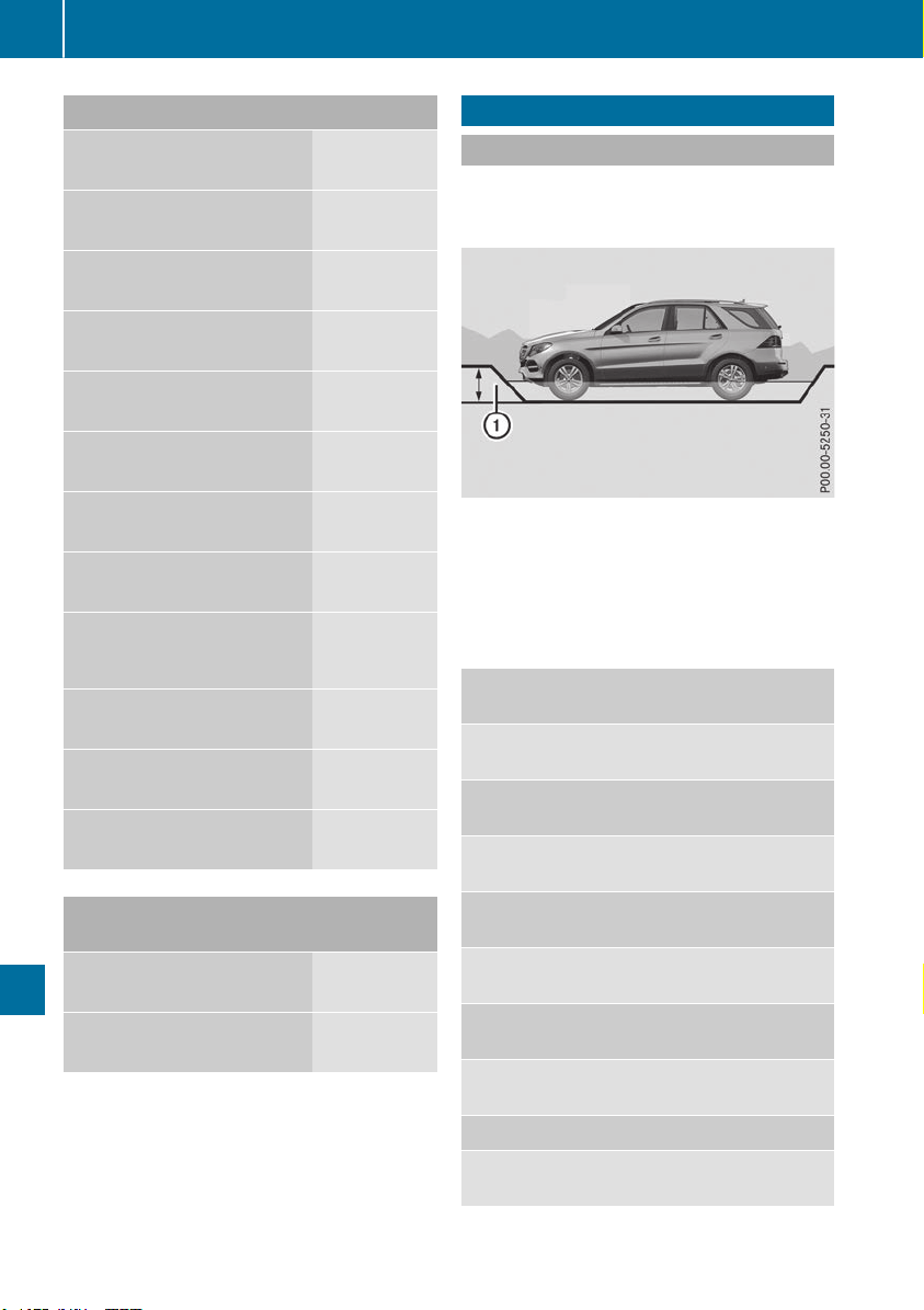
All other models
Vehicle width including
exterior mirrors
84.3 in
(2141 mm)
Maximum vehicle height
(steel suspension)
70.7 in
(1796 mm)
Maximum vehicle height
(AIRMATIC package)
71.6 in
(1818 mm)
Maximum vehicle height
(ON&OFFROAD package)
72.8 in
(1848 mm)
Minimum vehicle height
69.2 in
(1758 mm)
Wheelbase
114.8 in
(2915 mm)
Maximum ground clear-
ance (steel suspension)
8.0 in
(202 mm)
Maximum ground clear-
ance (AIRMATIC package)
10.0 in
(255 mm)
Maximum ground clear-
ance (ON&OFFROAD pack-
age)
11.2 in
(285 mm)
Minimum ground clear-
ance
7.1 in
(180 mm)
Turning circle
38.7 ft
(11.80 m)
Maximum roof load
220 lb
(100 kg)
Model Vehicle
length
GLE 400 4MATIC
GLE 550 4MATIC
189.5 in
(4813 mm)
All other models
189.7 in
(4819 mm)
Vehicle data for off-road driving
Fording depth
!
The depth of water must not exceed the
value specified in the table. Note that the
possible fording depth is less in flowing water.
:
Fording depth
On vehicles with the AIRMATIC package or the
Off-Road Engineering package, loads up to the
maximum permissible load have no influence on
fording capability.
Missing values were not available at the time of
going to print.
Fording
depth
Steel-sprung vehicles
19.7 in
(50 cm)
Vehicles with the AIRMATIC
package
Raised level 19.7 in
(50 cm)
Vehicles with the Off-Road
Engineering package
Off-road level 1 19.7 in
(50 cm)
Off-road level 2 19.7 in
(50 cm)
Off-road level 3 23.6 in
(60 cm)
Mercedes-AMG vehicles
Raised level 19.7 in
(50 cm)
392
Vehicle data for off-road driving
Technical data
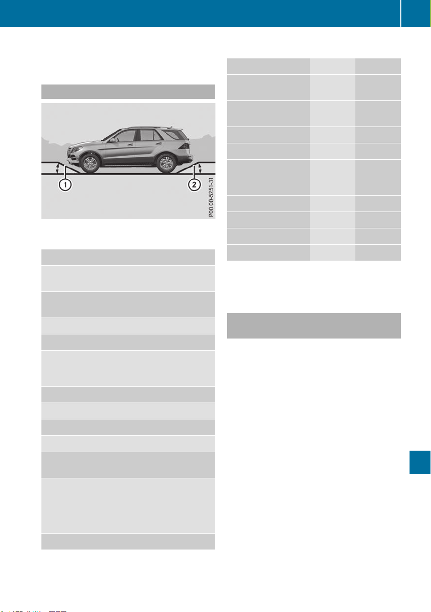
For more information about off-road fording, see
(Y page 164).
Approach/departure angle
All vehicles (except vehicles with AMG body-
styling)
:: ;;
Steel-sprung vehi-
cles
26° 26°
Vehicles with the
AIRMATIC package
Normal level 23° 24°
Raised level 29° 28°
Vehicles with the
Off-Road Engineer-
ing package
Normal level 23° 24°
Off-road level 1 26° 26°
Off-road level 2 29° 28°
Off-road level 3 30° 29°
Mercedes-AMG
vehicles
Normal level (in sport
mode with AMG
adaptive sport sus-
pension system acti-
vated)
21° 24°
Raised level 23° 24°
Vehicles with AMG bodystyling
:: ;;
Steel-sprung vehi-
cles
23° 26°
Vehicles with the
AIRMATICpackage
Normal level 22° 24°
Raised level 26° 28°
Vehicles with the
Off-Road Engineer-
ing package
Normal level 22° 24°
Off-road level 1 24° 26°
Off-road level 2 26° 28°
Off-road level 3 28° 29°
For further information about approach/depar-
ture angles, see (Y page 168).
Maximum gradient-climbing capabil-
ity
Note that the vehicle's gradient-climbing capa-
bility depends on the off-road conditions and the
road surface conditions.
Vehicles with the Off-Road Engineering
package: the maximum gradient climbing abil-
ity is 100 % when the LOW RANGE off-road gear
is selected.
Mercedes-AMG vehicles: the maximum gradi-
ent climbing ability is 80 %.
Vehicles without the Off-Road Engineering
package: the maximum gradient climbing abil-
ity is 80 %.
GLE 550 e 4MATIC: the maximum gradient
climbing ability is 50 %.
Accelerate carefully and make sure that the
wheels do not spin when driving on steep ter-
rain.
i
If the load on the front axle is reduced when
pulling away on a steep uphill slope, the front
wheels have a tendency to spin. 4ETS recog-
nizes this and brakes the wheels accordingly.
The rear wheel torque is increased, making it
easier to drive off.
Vehicle data for off-road driving
393
Technical data
Z
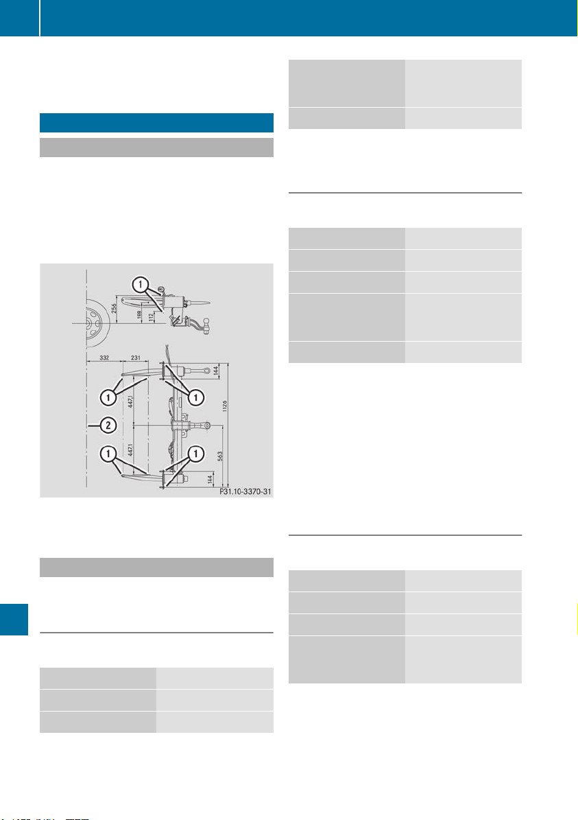
For further information about the maximum gra-
dient climbing ability, see (Y page 168).
Trailer tow hitch
Mounting dimensions
!
If you have a trailer tow hitch retrofitted,
changes to the cooling system and drive train
may be necessary, depending on the vehicle
type.
If you have a trailer tow hitch retrofitted,
observe the anchorage points on the chassis
frame.
:
Anchorage points for the trailer tow hitch
;
Rear axle center line
Trailer loads
Permissible trailer load, braked (at a
minimum gradient-climbing capability
of 12% from a standstill)
Missing values were not available at the time of
going to print.
All models
7200 lbs (3265 kg)
GLE 300 d 4MATIC
6615 lbs (3000 kg)
GLE 350
6615 lbs (3000 kg)
Mercedes-
AMG GLE 43 4MATI
C
GLE 550 e 4MATIC
4410 lbs (2000 kg)
Maximum drawbar noseweight (the
drawbar noseweight is not included in
the trailer load)
Missing values were not available at the time of
going to print.
All models
575 lbs (261 kg)
GLE 300 d 4MATIC
530 lbs (240 kg)
GLE 350
530 lbs (240 kg)
Mercedes-
AMG GLE 43 4MATI
C
GLE 550 e 4MATIC
355 lbs (160 kg)
The actual noseweight may not be higher than
the value which is given. The value can be found
on the trailer tow hitch or trailer identification
plates. The lowest weight applies.
The maximum permissible trailer drawbar nose-
weight is the maximum weight with which the
trailer drawbar can be loaded. Limit for
Mercedes-Benz-approved trailer couplings.
Gross rear axle weight rating when tow-
ing a trailer
Missing values were not available at the time of
going to print.
All models
3527 lbs (1600 kg)
GLE 300 d 4MATIC
3638 lbs (1650 kg)
GLE 350 d 4MATIC
3638 lbs (1650 kg)
Mercedes-
AMG GLE 43 4MATI
C
394
Trailer tow hitch
Technical data
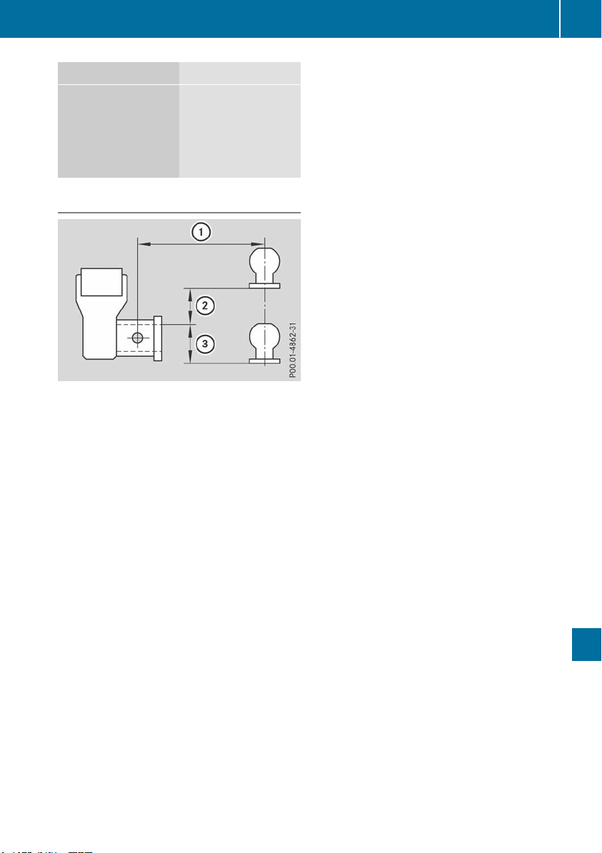
GLE 550 e 4MATIC
3704 lbs (1680 kg)
Mercedes-
AMG GLE 63 4MATI
C
Mercedes-
AMG GLE 63 S 4MA
TIC
3858 lbs (1750 kg)
Ball position of the ball coupling
:
7.5"
;
2"
=
2.75"
When choosing a ball coupling, the dimensions
stated in the illustration must not be exceeded.
Trailer tow hitch
395
Technical data
Z