INSTALLATION INSTRUCTIONS Whirlpool
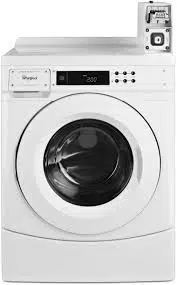
COMMERCIAL FRONT-LOAD WASHERWASHER SAFETY
IMPORTANT SAFETY INSTRUCTIONS
WARNING: To reduce the risk of fire. electric shock, or injury to persons when using the washer, follow basic precautions. including the following:
- Read all instructions before using the washer
- Do not wash articles that have been previously cleaned in, washed in. soaked in, or spotted with gasoline. dry-cleaning solvents. other flammable, or explosive substances as they give off vapors that could ignite or explode
- Do not add gasoline, dry-cleaning solvents, or other flammabl, or explosive substances to the wash water. These substances give off vapors that could ignite or explode.
- Under certain conditions, hydrogen gas may be produced in a hot water system that has not been used for 2 weeks or more. HYDROGEN GAS IS EXPLOSIVE. If the hot water system has not been used for such a period, before using the washing machine, turn on all hot water faucets and let the water flow from each for several minutes. This will release any accumulated hydrogen gas. As the gas is flammable, do not smoke or use an open flame during this time.
- Do not allow children to play on or in the washer. Close supervision of children is necessary when the washer is used near children.
- Before the washer is removed from service or discarded, remove the door or lid
- Do not reach into the washer if the drum, tub or agitator is moving.
- Do not install or store the washer where it will be exposed to the weather
- Do not tamper with controls.
- Do not repair or replace any part of the washer or attempt any servicing unless specifically recommended in this manual or in published user-repair instructions that you understand and have the skills to carry out.
- See “Electrical Requirements” for grounding instructions.
INSTALLATION REQUIREMENTS
Tools and Parts
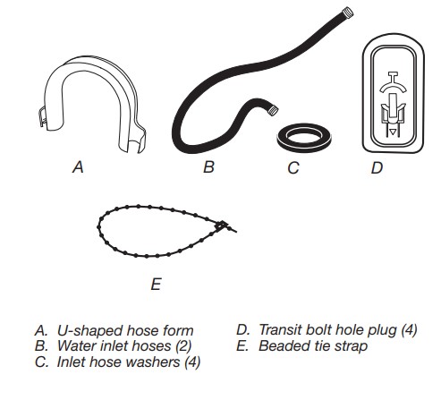
Gather the required tools and parts before starting installation.The parts supplied are in the washer drum.
Tools needed for connecting the water inlet hoses:
- Pliers (that open to Flashlight (optional)
- 1%c" [39.5 mm)
Tools needed for installation:
- Open-end wrenches 1/2" and 9/16" m
- TORX 720" security screwdriver
- 1/4" nut driver
- Level
- Wood block
- Ruler or measuring tape
Part supplied
Alternate Parts
Your installation may require additional parts. If you are interested in purchasing one of the items listed here. call the toll-free number in “Accessories.”
If you have - You will need to buy
- Laundry tub or standpipe taller than 96" (2.4 m)
- Sump pump system (if not alreadyavailable)
- Overhead sewer
- Standard 20 gal. (76 L). 30" (762 mm) tall drain tub or utility sink and sump pump (available from local plumbing suppliers)
- Floor drain
- Siphon break. Part Number 28583; additional drain hose, Part Number 8318155; and connector kit, Part Number 285835
- Drain hose too short
- 4 ft (1.2 m) drain hose extension kit. Part Number 285863
- Water faucets beyond reach of fill hoses
- 2 longer water fill hoses:
- 6 ft (1.8 m). Part Number 76314
- 10 ft (3.0 m). Part Number 350008
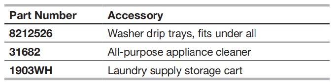
Accessories
Enhance your washer with these premium accessories.
For more high-quality items or to order, call 1-866-698-2538
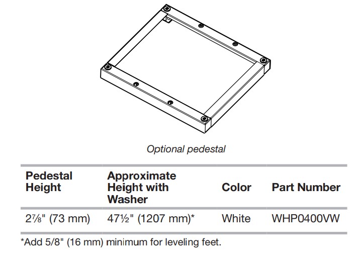
Options
Pedestal
You have the option of purchasing pedestals separately for this washer. The pedestal will add to the total height of the washer.
Location Requirements
Selecting the proper location for your washer improves performance and minimizes noise and possible washer “walk.” Your washer can be installed under a custom counter or in a basement, laundry room, or recessed area. See “Drain System.” Companion appliance location requirements should also be considered. Proper installation is your responsibility.
You will need:
- A water heater set to deliver 120°F (49°C) water to the washer.
- A grounded electrical outlet located within 6 ft (1.8 m) of where the power cord is attached to the back of the washer. See “Electrical Requirements.”
- Hot and cold water taps located within 4 ft (1.2 m) of the hot and cold water fill valves, and water pressure of 20–100 psi (137.9–689.6 kPa).
- A level floor with a maximum slope of 1" (25 mm) under entire washer. Installing the washer on soft floor surfaces, such as carpets or surfaces with foam backing, is not recommended.
- A sturdy and solid floor to support the washer with a total weight (water and load) of 400 lbs (180 kg). Do not operate your washer in temperatures below 32°F (0°C). Some water can remain in the washer and can cause damage in low temperatures.
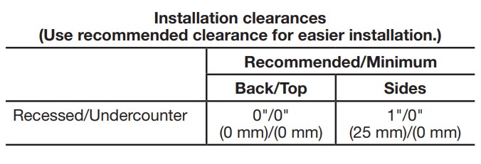
Installation clearances
- The location must be large enough to allow the washer door to be fully opened.
- Additional spacing should be considered for ease of installation and servicing. The door opens more than 90° and is not reversible.
- Additional clearances might be required for wall, door, and floor moldings.
- Additional spacing of 1" (25 mm) on all sides of the washer is recommended to reduce noise transfer.
- Companion appliance spacing should also be considered. Recessed area installation This washer may be installed in a recessed area. The installation dimensions shown are the minimum spaces allowable. Additional spacing should be considered for ease of installation and servicing. See the chart below.
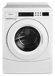
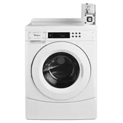
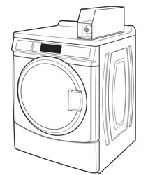
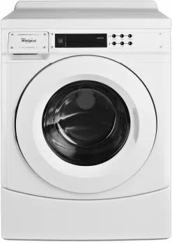
Washer Dimensions
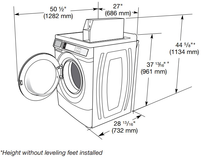
NOTE: The door is not reversible.
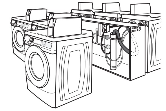
A floor drain should be provided under the bulkhead. Prefabricated bulkheads with electrical outlets, water inlet lines, and drain facilities should be used only where local codes permit.
Drain System
The washer can be installed using the standpipe drain system (floor or wall), the laundry tub drain system, or the floor drain system. Select the drain hose installation method you need. See “Tools and Parts.”
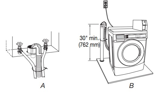
Standpipe drain system – wall or floor (views A & B)
The standpipe drain requires a minimum diameter standpipe of 2" (50 mm). The minimum carry-away capacity can be no less than 12 gal. (45.5 L) per minute, per washer. The top of the standpipe must be at least 30" (762 mm) high and no higher than 96" (2.4 m) from the bottom of the washer.
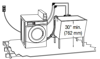
Laundry tub drain system
The laundry tub needs a minimum 20 gal. (76 L) capacity. The top of the laundry tub must be at least 30" (762 mm) above the floor.
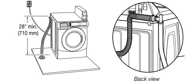
Floor drain system
The floor drain system requires a siphon break that may be purchased separately. See “Tools and Parts.” The siphon break must be a minimum of 28" (710 mm) from the bottom of the washer. Additional hoses might be needed.
Electrical Requirements
- A 120-volt, 60 Hz., AC-only, 15- or 20-amp, fused electrical supply is required. A time-delay fuse or circuit breaker is recommended. It is recommended that a separate circuit serving only this washer be provided.
- This washer is equipped with a power supply cord having a 3 prong grounding plug.
- To minimize possible shock hazard, the cord must be plugged into a mating, 3 prong, grounding-type outlet, grounded in accordance with local codes and ordinances. If a mating outlet is not available, it is the personal responsibility and obligation of the customer to have the properly grounded outlet installed by a qualified electrician.
- If codes permit and a separate ground wire is used, it is recommended that a qualified electrician determine that the ground path is adequate.
- Do not ground to a gas pipe.
- Check with a qualified electrician if you are not sure the washer is properly grounded.
- Do not have a fuse in the neutral or ground circuit.
INSTALLATION INSTRUCTIONS
Remove Transport System
IMPORTANT: Position the washer so that the rear of the washer is within approximately 3 ft (900 mm) of its final location. There are 4 shipping bolts in the rear panel of the washer that support the suspension system during transportation. These bolts also retain the power cord inside the washer until the bolts are removed.
- Keep the washer in the upright position while removing the shipping bolts
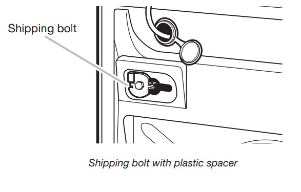
- Using a ½" wrench, loosen each of the bolts.
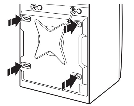
- Once the bolt is loose, move it to the center of the hole and completely pull out the bolt, including the plastic spacer covering the bolt.
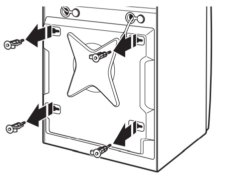
- Once all 4 bolts are removed, discard the bolts and spacers. Push the power cord plug into the opening on the right side of the rear panel and pull the power cord through the opening on the left side of the rear panel; then close holes with the attached cap. Do not pull plug end of power cord through the right side hole.
- Close the bolt holes with the 4 transport bolt hole plugs.
NOTE: If the washer is to be transported at a later date, call your product distributor or installer. To avoid suspension and structural damage, your washer must be properly set up for relocation by a trained professional.
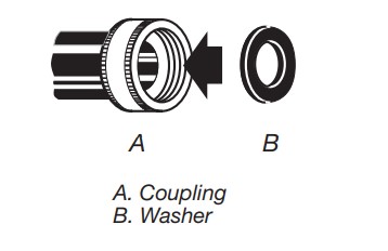
Connect the Inlet Hoses
Insert new flat washers (supplied) into each end of the inlet hoses. Firmly seat the washers in the couplings.
Connect the inlet hoses to water faucets
Make sure the washer drum is empty.
- Attach a hose to the hot water faucet. Screw on coupling by hand until it is seated on the washer.
- Attach a hose to the cold water faucet. Screw on coupling by hand until it is seated on the washer.
- Using pliers, tighten the couplings with an additional two-thirds turn.
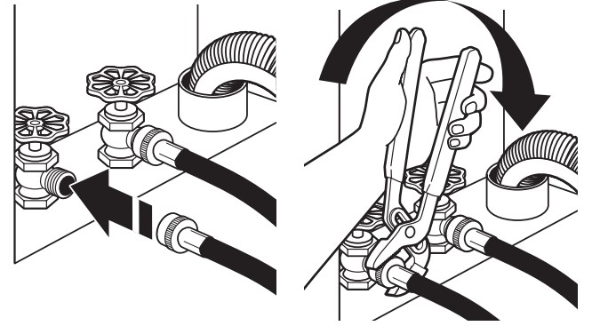
NOTE: Do not overtighten or use tape or sealants on the valve. Damage to the valves can result.
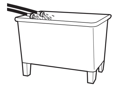
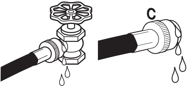
Clear water lines
- Run water through both faucets and inlet hoses, into a laundry tub, drainpipe, or bucket, to get rid of particles in the water lines that might clog the inlet valve screens.
- Check the temperature of the water to make sure that the hot water hose is connected to the hot water faucet and that the cold water hose is connected to the cold water faucet.
Connect the inlet hoses to the washer
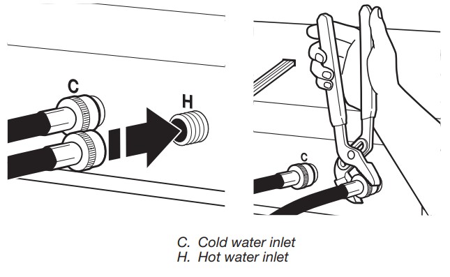
- Attach the hot water hose to the check valve on washer’s hot (H) water inlet valve. Screw on coupling by hand until it is seated on the check valve.
- Attach the cold water hose to the check valve on washer’s cold (C) water inlet valve. Screw on coupling by hand until it is seated on the check valve.
- Using pliers, tighten the couplings with an additional two-thirds turn.
NOTE: Do not overtighten. Damage to the coupling can result. - Turn on the water faucets completely and check for leaks at water faucets and washer connections.
NOTE: Replace inlet hoses after 5 years of use to reduce the risk of hose failure. Record hose installation or replacement dates on the hoses for future reference. Periodically inspect and replace hoses if bulges, kinks, cuts, wear, or leaks are found.
Connect the Drain Hose
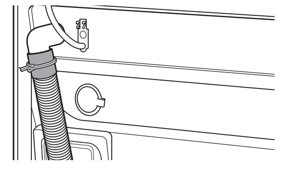
Remove drain hose from washer drum
- Using locking pliers, squeeze hose clamp tabs together and insert over the end of drain hose.
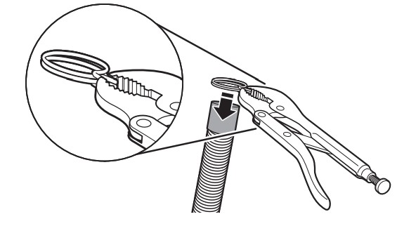
- Slide drain hose onto washer connection.
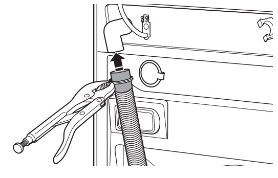
- Once drain hose is in place, release pliers.
Washer drain system can be installed using a floor drain, wall standpipe, floor standpipe, or laundry tub.
Laundry tub drain or standpipe drain
Connect the drain hose form to the corrugated drain hose.
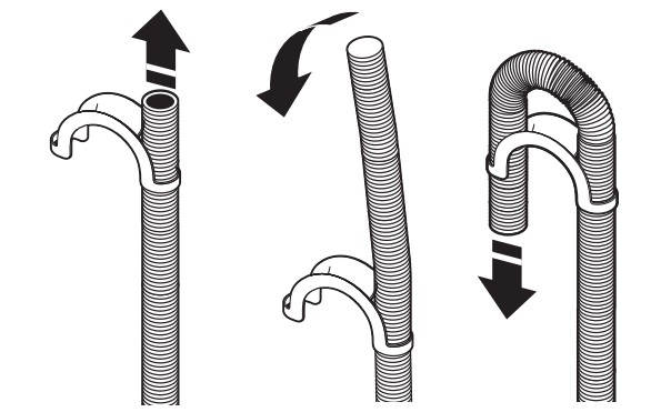
To keep drain water from going back into the washer:
- Use the drain hose form and do not force excess drain hose into standpipe. Hose should be secure but loose enough to provide a gap for air.
- Do not lay excess hose on the bottom of the laundry tub.
Floor drain: You may need additional parts. See “Floor drain” under “Tools and Parts.”
Secure the Drain Hose
Drain hose must be secured to stop the hose from moving when water is pumped out. If the drain hose moves, water may end up on the floor.
- Drape the power cord over the washer top.
- Move the washer to its final location.
- Place the drain hose in the laundry tub or standpipe as shown. See illustrations A and B.
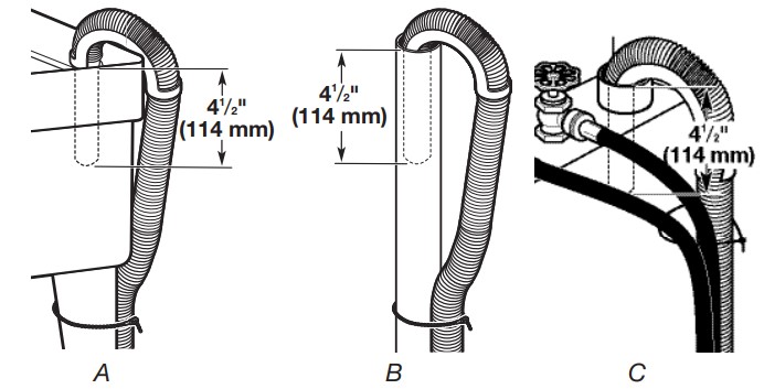
NOTES:
- Do not force excess drain hose back into the rear of the washer.
- To avoid siphoning, do not seal or put more than 4½" (114 mm) of the drain hose into drainpipe or standpipe.
- If the washer faucets and the drain standpipe are recessed, put the hooked end of the drain hose in the standpipe as shown. See illustration C.
- It is the responsibility of the installer to install and secure the drain hose into the provided plumbing/drain in a manner that will avoid the drain hose coming out of, or leaking from, the plumbing/drain.
Level the Washer
Properly leveling your washer avoids excessive noise and vibration.
- Check the levelness of the washer by placing a level on the top edge of the washer, first side to side, then front to back.
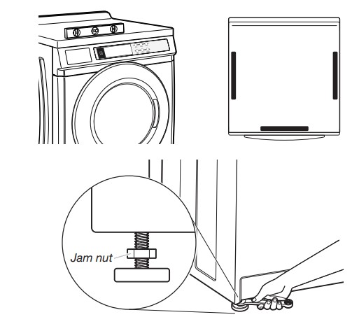
If the washer is against a wall, move the washer out slightly before tipping back. If the washer is not level, first prop the front with a wood block and adjust the feet as necessary; then prop the back and adjust feet as necessary. Repeat this step until washer is level. - Make sure all 4 feet are stable and resting on the floor. Then check that the washer is perfectly level (use a level).
- After the washer is level, use a 9/16" open-end wrench to turn the nuts on the feet tightly against the washer cabinet.
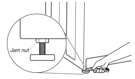
IMPORTANT: All 4 feet must be tightened. If the nuts are not tight against the washer cabinet, the washer may vibrate. - The washer should not move front to back, side to side, or diagonally when pushed on its top edges.
- Slide the washer to its final location.
- Confirm the levelness of the washer
Complete Installation
- Check the electrical requirements. Be sure that you have the correct electrical supply and the recommended grounding method. See “Electrical Requirements.”
- Check that all parts are now installed. If there is an extra part, go back through the steps to see which step was skipped.
- Check that you have all of your tools.
- Dispose of/recycle all packaging materials.
- Check that the water faucets are on.
- Check for leaks around faucets and inlet hoses.
- Plug into a grounded 3 prong outlet.
- To test and clean your washer, measure ½ of the detergent manufacturer’s recommended amount of High Efficiency (HE) detergent for a medium-size load. Pour the detergent into the detergent dispenser. Select any cycle and allow the washer to complete one whole cycle.

USER & SET-UP INSTRUCTIONS

General User Information
SCROLLING ‘OUT OF ORDER’ SHOWING IN DISPLAY
This condition indicates the washer is inoperative.
‘0 MINUTES’ SHOWING IN DISPLAY
This indicates the cycle is complete and the washer cannot be operated. Coins dropped or debit inputs during this condition will be stored in escrow but cannot be used until normal operation is restored by opening and closing the door. If a door switch fails, it must be replaced before normal operation can be restored.
COLD START (Initial first use)
Washer is programmed at the factory as follows: 11-minute wash period 3 rinses (extra rinse not enabled) $2.00 wash price (9150 model) $0 wash price (9160 model)
WARM START (after power failure)
A few seconds after power is restored, if a cycle was in progress at the time of the power failure, ‘RESELECT CYCLE’ will flash in the display, indicating the need for a button press to restart the washer.
DOOR LOCK
Prior to beginning a cycle, there is a door lock routine of lock/ unlock/relock; then the cycle begins. The door will remain locked until the end of a cycle or approximately 2 minutes after a power interruption.
PRICING
After the door is opened following the completion of a cycle, the display indicates the cycle price (unless set for free operation). As coins are dropped or debit inputs arrive, the display will change to lead the user through the initiation of a cycle.
FREE CYCLES
This is established by setting the cycle price to zero. When this happens, ‘SELECT CYCLE’ will appear rather than a cycle price.
DEBIT CARD READY
This washer is debit card ‘cable’ ready. It will accept a variety of debit card systems but does NOT come with a debit card reader. Refer to the debit card reader manufacturer for proper washer setup. In models converted to a Generation 1 debit card system, debit pulses represent the equivalent of one coin (coin 1).
Control Set-Up Procedures
IMPORTANT: Read all instructions before operating.
- 9150 Models: Insert access door key, turn, and lift to remove access door.
- 9160 Models: Once the debit card reader is installed (according to the reader manufacturer’s instructions), the set-up mode can only be entered by inserting a set-up card (supplied by the reader manufacturer) into the card slot. If a set-up card is not available, diagnostic modes can be entered by removing connector AA1 on the circuit board or by using the Service Access Code (see “Service Access Code” section, page 13) for 9160 models.
IMPORTANT: Unplug washer or disconnect power before opening the console. To access connector AA1:
- Unplug washer or disconnect power.
- Open console, disconnect plug on AA1, and close console.
- Plug in washer or reconnect power. The washer is now in the set-up mode. The lower 3 buttons and the digital display are used to set up the controls. The display can contain 4 numbers and/or letters and a decimal point. These are used to indicate the set-up codes and related code values available for use in programming the washer. Once the washer has been programmed with a Generation 2 card reader installed, the washer will be in dAS mode permanently and dAS will be displayed every time set-up mode is accessed. The lower fabric setting buttons and the digital display are used to set up the controls. The display can contain 4 numbers and/or letters and a decimal point. These are used to indicate the set-up codes and related code values available for use in programming the washer.
HOW TO USE THE BUTTONS TO PROGRAM THE CONTROLS
- The Hot button is used to adjust the values associated with set-up codes. Pressing the button will change the value by increments. Rapid adjustment is possible by holding down the button.
- The Warm button will advance through the set-up codes. Pressing the button will advance to the next available set-up code. Holding the button down will automatically advance through the set-up codes at a rate of 1 per second.
- The Cold button is used to select or deselect options.
Start Operating Setup
Before proceeding, it is worth noting that, despite all of the options available, an owner can simply choose to uncrate a new commercial washer, hook it up, plug it in, and have a washer that operates. Washers are preset at the factory for an 11-minute wash period and 3 rinses (no extra rinse).
SET-UP CODES
The WARM button will advance you from code to code.
The HOT button will change the code value.
The COLD button will select or deselect options. The set-up code is indicated by the one or two left-hand characters. The set-up code value is indicated by the two or three right-hand characters.
NOTE: The first line of each code indicates the factory default for 9150 models
- 6. 08: REGULAR CYCLE PRICE (Factory Default)
- 6. 08: When the d.xx is set to d.00, this 6.xx value represents the number of coins needed to start the washer; may adjust from 0–39. Change this value by pressing the HOT button. 6.08 = 8 coins. 9160 models default to 6.00.
- 6. 01: When the d.xx is set to d. CS, this 6.xx value represents the number of push-in actuations of the coin slide to start the washer. 6.01 would equal one coin slide activation.
-> Press the WARM button once to advance to next code.
- 7. 11: WASH LENGTH
- 7. 11: This is the number of minutes for WASH. Washer comes from the factory preset with 11 minutes. Choose from 9–17 minutes by pressing the HOT button.
->Press the WARM button once to advance to next code.
- 8. 00: ADDITIONAL RINSE OPTION. This option is either SELECTED ‘ON’ or NOT SELECTED ‘OFF’.
- 8. 00: Not Selected ‘OFF’.
- 8. Ar: Selected ‘ON’. Press the COLD button once for this selection.
->Press the WARM button once to advance to next code.
- 9. 00: CYCLE COUNTER OPTION This option is either SELECTED ‘ON’ or NOT SELECTED ‘OFF’.
- 9.00: Not Selected ‘OFF’.
- 9.0C: Selected ‘ON’ and not able to be deselected. Press the COLD button 3 consecutive times to select ‘ON’. Once selected ‘ON,’ it cannot be deselected.
->Press the WARM button once to advance to next code.
- 1. 00: MONEY COUNTER OPTION This option is either SELECTED ‘ON’ or NOT SELECTED ‘OFF’
- 1.00: Not Selected ‘OFF’.
- 1.0C:Selected ‘ON’. Press the COLD button three consecutive times to select ‘ON’ and three consecutive times to remove (Not Selected ‘OFF’). Counter resets by going from ‘OFF’ to ‘ON’.
- 1.C0: Selected ‘ON’ and not able to be deselected. To select ‘ON’ and not able to be deselected, first select ‘ON’, then within two seconds, press the COLD button twice, HOT once, and exit the set-up mode.
->Press the WARM button once to advance to next code.
- 2. 00: SPECIAL PRICING OPTIONS This option is either SELECTED ‘ON’ or NOT SELECTED ‘OFF’.
- 2. 00 Not Selected ‘OFF’.
- 2. SP: Selected ‘ON’. Press the COLD button once for this selection. If SPECIAL PRICING OPTION is selected, there is access to codes ‘3.’ thru ‘9.’
->Press the WARM button once to advance to next code.
OPTIONS TO USE IF SPECIAL PRICING IS SELECTED:
- 3. 08: SPECIAL CYCLE PRICE
- 3. 08: Represents the number of quarters (coin 1) needed to start the washer; may adjust from 0–39. (See b.xx setup for VALUE OF COIN 1.) Advance from 0–39 by pressing HOT. Factory default of 8 quarters = $2.00.
- 3. 00: Model 9160: Factory default of 0 quarters.
-> Press the WARM button once to advance to next code.
- 5. 00 :TIME-OF-DAY CLOCK, MINUTES
- 5. 00 g This is the TIME-OF-DAY CLOCK, minute setting; select 0–59 minutes by pressing the HOT button.
-> Press the WARM button once to advance to next code.
- 6. 00 TIME-OF-DAY CLOCK, HOURS
NOTE: Uses military time – 24 hr. clock.- 6. 00: This is the TIME-OF-DAY CLOCK, hour setting; select 0–23 hours by pressing the HOT button.
-> Press the WARM button once to advance to next code.
- 7. 00: SPECIAL PRICE START HOUR NOTE: Uses military time – 24 hr. clock.
- 7. 00: This is the start hour; select 0–23 hours. Select START HOUR by pressing the HOT button.
->Press the WARM button once to advance to next code.
- 8. 00: SPECIAL PRICE STOP HOUR
NOTE: Uses military time – 24 hr. clock.- 8. 00: This is the stop hour; select 0–23 hours. Select STOP HOUR by pressing the HOT button.
->Press the WARM button once to advance to next code.
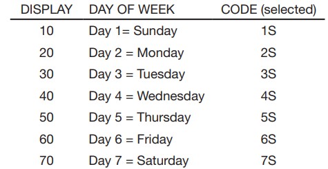
- 9. 10: SPECIAL PRICE DAY
- 9. 10: This represents the day of the week and whether special pricing is selected for that day. A number followed by ‘0’ indicates no selection for that particular day (9.10). A number followed by an ‘S’ indicates selected for that day (9.1S). Day of week (1–7) can be chosen by pressing the HOT button. Press the COLD button once to select special pricing for each day chosen. When exiting set-up code ‘9.’, the display must show current day of week:
->Press the WARM button once to advance to next code.
- A. 00: VAULT VIEWING OPTION This option is either SELECTED ‘ON’ or NOT SELECTED ‘OFF’.
- A. 00: Not Selected ‘OFF’.
- A. SC g Selected ‘ON’. Press the COLD button once for this selection. When selected, the money and/or cycle counts will be viewable (if counting is selected) when the coin box is removed.
->Press the WARM button once to advance to next code.
- b. 40: VALUE OF COIN 1
- b. 05: This represents the value of coin 1 in number of nickels: 05 = $0.25. By pressing the HOT button, there is an option of 1–199 nickels. With coin slide activation, this represents the total vend price in nickels. Example: b.40 is equal to $2.00.
->Press the WARM button once to advance to next code.
- C. 20: VALUE OF COIN 2
- C. 20: This represents the value of coin 2 in number of nickels: 20 = $1.00.
- C.05: By pressing the HOT button, there is the option of 1–199 nickels.
-> Press the WARM button once to advance to next code.
- d. 00 COIN SLIDE OPTION This option is either SELECTED ‘ON’ or NOT SELECTED ‘OFF’. Replacement of meter case will be needed for coin slide mounting.
- d. 00: Not Selected ‘OFF’.
- d.CS: Selected ‘ON’.
NOTE: This option needs to be set to ‘00’ unless the meter case has been changed to accept a coin slide device.
Press the COLD button 3 consecutive times for this selection. When coin slide mode is selected, set ‘b.’ equal to value of vend price in nickels. Set ‘6 XX’ (REGULAR CYCLE PRICE) and ‘3.XX’ (SPECIAL CYCLE PRICE) to number of slide operations.
NOTE: If the installer sets up ‘CS’ on a coin drop model, the washer will not register coins inserted.
->Press the WARM button once to advance to next code.
- E. 00: ADD COINS OPTION This option is either SELECTED ‘ON’ or NOT SELECTED ‘OFF’. This option causes the customer display to show the number of coins (coin 1) to enter, rather than the dollars-and-cents amount.
- E. 00: Not Selected ‘OFF’.
- E. AC: Selected ‘ON’.
Press the COLD button 3 consecutive times for this selection. PR MODELS ONLY: In enhanced debit mode, this option is not selectable.
->Press the WARM button once to advance to next code.
- F. 00: ENHANCED PRICING OPTION
- F. 00 SU g Not Selected ‘OFF’.
- F.SU: Super Cycle pricing enabled. This option allows customers to upgrade cycles by depositing extra money. Set-up codes ‘H.’ and ‘h.’ will be displayed only when this option is enabled. Press the COLD button for this selection.
->Press the WARM button once to advance to next code.
- H. 01: SUPER CYCLE UPGRADE PRICE (Skipped unless Super Cycle pricing is enabled.)
- H. 01: This represents the number of coin 1 required to upgrade a base cycle to a Super Cycle. Advance from 0–33 by pressing the HOT button.
->Press the WARM button once to advance to next code.
- h. 01: SUPER CYCLE TYPE (Skipped, unless Super Cycle pricing is enabled.)
- h. 01: This represents the Super Cycle upgrade option. Press the HOT button to step through upgrade options 1 through 3 as follows: 01 – enhanced wash, extra 3 minutes of wash tumble in addition to the programmed wash time. 02 – extra rinse for all cycles. 03 – both 01 and 02.
->Press the WARM button once to advance to next code.
- J. Cd COIN/DEBIT OPTION
- J.Cd: Both coin and debit selected. Press the COLD button 3 consecutive times for this selection (default for 9150 models).
- J.C_: Coins selected, debit disabled. Press the COLD button 3 consecutive times for this selection.
- J._d: Debit card selected, coins disabled. Press the COLD button 3 consecutive times for this selection (default for 9160 models).
- J.Ed: Enhanced Debit is self-selected when a Generation 2 card reader is installed in the washer. The Ed option cannot be manually selected or deselected.
->Press the WARM button once to advance to next code.
- L. 00: PRICE SUPPRESSION OPTION This option is either SELECTED ‘ON’ or NOT SELECTED ‘OFF’. This option causes the customer display to show ‘AVAILABLE’ or ‘ADD’ rather than the amount of money to add (used mainly in debit installations).
- L. 00: Not Selected ‘OFF’.
- L. PS: Selected ‘ON’. Press the COLD button once for this selection. Press the WARM button once to advance to next code.
- n. CE: CLEAR ESCROW OPTION When selected, money held in escrow for 30 minutes without further escrow or cycle activity will be cleared.
- n.00: Not Selected ‘OFF’.
- n.CE: Selected ‘ON’. Press the COLD button once for this selection.
->Press the WARM button once to advance to next code.
- U. 00: PENNY INCREMENT OFFSET
- U. 00: This represents the penny increment price offset used with Generation 2 (Enhanced Debit) card readers. Choose from 0–4 pennies by pressing the HOT button.
->Press the WARM button once to advance to next code.
- A1. 00: PREWASH LENGTH
- A1. 00: This is the number of minutes of PREWASH. Choose 0 to disable the prewash or select between 2 and 7 minutes by pressing the HOT button.
->Press the WARM button once to advance to next code.
EXIT FROM SET-UP MODE
- CHW9150 Models:
- CHW9160 Models:
- Unplug washer or disconnect power.
- Open console, reinsert plug into AA1, and close console.
- Plug in washer or reconnect power.
- MODEL CHW9150 SET UP AS PN WITH PROGRAMMING SWITCH:
- Turn key clockwise and remove.
- MODEL CHW9160 SET UP AS PN WITHOUT PROGRAMMING SWITCH:
- Set-up mode can be exited by using procedures from “Service Access Code.”
SERVICE ACCESS CODE
This code can be entered to access service mode without removing the console. It only functions on washers set up for 0 vend price without any Special Pricing setup, and the Coin/Debit Option must be set to “J._d”. If the washer is not in failure mode, the door must be opened to proceed. Service Access Code contains 4 steps. Perform the following steps:
- Press the upper left button.
- Press the lower right button.
- Press the upper right button.
- Press the lower left button.
NOTE: If the Service Access Code procedure is not completed properly, as noted above, there is a 15-second delay before it can be attempted again. There are 3 options to exit from the Service Mode:
- From Set-up Code 8, press button #1 for 4 seconds.
- Wait 2 minutes without touching any buttons (without diagnostic modes running).
- Power down the washer; then reapply power.
WASHER CARE
Cleaning Your Washer
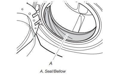
Cleaning the Door Seal/Bellow
- Open the washer door and remove any clothing or items from the washer.
- Inspect inner glass door. If debris is present, wipe off debris using damp cloth.
- Inspect the colored seal/bellow between the door opening and the drum for stained areas. Pull back the seal/bellow to inspect all areas under the seal/bellow and to check for foreign objects.
- If stained areas are found, wipe down these areas of the seal/ bellow using the procedure that follows:
- Mix a dilute solution, using 3/4 cup (177 mL) of liquid chlorine bleach, and 1 gal. (3.8 L) of warm tap water.
- Wipe the seal/bellow area with the dilute solution, using a damp cloth.
- Let stand 5 minutes.
- Wipe down area thoroughly with a dry cloth and let the washer interior air dry with door open.
IMPORTANT:
- Wear rubber gloves when cleaning for prolonged periods.
- Refer to the bleach manufacturer’s instructions for proper use.
Washer Maintenance Procedure
This washer has a special cycle that uses higher water volumes in combination with liquid chlorine bleach to thoroughly clean the inside of the washer.
NOTES:
- Read these instructions completely before beginning the cleaning process.
- If necessary, the cleaning cycle may be interrupted by pressing the COLD button twice. However, this will not immediately stop the cycle. The washer will continue with several rinse and drain steps to ensure that all remaining bleach is rinsed from the washer.
Begin procedure
- Open the washer door and remove any clothing or items from the washer.
- Use liquid chlorine bleach: Open the dispenser drawer and immediately add 2/3 cup (160 mL) of liquid chlorine bleach to the bleach compartment. NOTE: Do not add any detergent to this cycle. Use of more than 2/3 cup (160 mL) of bleach will cause product damage over time.
- Close the washer door and the dispenser drawer.
- To start the Clean Washer cycle, first enter “Start Operating Set-up.” Then press and hold COLD for 1 second. With the entire display flashing, press COLORS/DELICATES.
NOTE: The drum will rotate, then the door will unlock, lock again, and then the cycle will continue.- The washer will not fill, but the drum will rotate while the washer runs a short sensing cycle. This will take approximately 3 minutes.
- The cycle will determine whether clothing or other items are in the washer.
- If no items are detected in the washer, it will proceed to Step 7.
- If any items are detected in the washer, “rL” or “F-34” will be displayed. Then the door will unlock.
- Press COLD to cancel the failure code. Then repeat steps 1, 3, and 4 to start the cycle again.
- Once the cycle has begun, allow the cycle to complete.
- After the cycle is complete, leave the door open slightly to allow for better ventilation and drying of washer interior.
Always do the following to maintain washer freshness - Use only “HE” High Efficiency detergent.
- Leave the door slightly open after each cycle to allow for better ventilation and drying of washer interior.
- Clean the washer monthly using the Washer Maintenance Procedure and 2/3 cup (160 mL) of liquid chlorine bleach.
- If the procedure does not sufficiently improve the washer freshness, please evaluate your installation and usage conditions for other causes.
Cleaning the exterior
Use a soft damp cloth or sponge to wipe up any spills. Occasionally wipe the outside of your washer to keep it looking new. Use mild soap and water. Do not use abrasive products.
Cleaning the dispenser drawer The dispenser drawer is removable for easy cleaning.
- Unlock the dispenser drawer by pressing the Release Lever. Remove the drawer.
- Remove the inserts (the siphon from the softener and bleach compartments).
- Wash the parts under running water. NOTE: Do not wash components in the dishwasher.
- Re-install the inserts and return the dispenser to the drawer
Water Inlet Hoses
Replace water inlet hoses after 5 years of use to reduce the risk of hose failure. Periodically inspect and replace water inlet hoses if bulges, kinks, cuts, wear, or leaks are found. When replacing your water inlet hoses, mark the date of replacement on the label with a permanent marker.