
USER GUIDE & SERVICE MANUAL
Model: UCBF659-SS12A

USER GUIDE & SERVICE MANUAL
Table of Contents
Click on any section below to jump directly there
Intro
Safety
Safety and Warning
Disposal And Recycling
Installation
Environmental Requirements
Electrical
General Installation
Interior Adjustments
Maintenance
Cleaning
Cleaning Condenser
Extended Non-Use
Operating Instructions
Control Operation
Service
Troubleshooting
Wire Diagram
Product Liability
Parts
System Diagnosis Guide
Compressor Specifications
Warranty
USER GUIDE
Introduction
WELCOME TO U-LINE
Congratulations on your U‑Line commercial purchase. Your product comes from a company with over ve decades of
premium modular ice making, refrigeration, and wine preservation experience. U‑Line continues to be the American leader
in refrigeration, delivering versatility and exibility for multiple applications, including: residential, commercial, outdoor and
marine use. U‑Line’s commercial collection includes reach‑in refrigerators and freezers, dispensers, ice machines, undercounter
refrigeration and wine, back bar refrigeration, blast chillers and shock freezers, base refrigerators and freezers, and pizza and
food prep tables.
U‑Line has captivated those who have an appreciation for the ner things combined with exceptional functionality, style,
inspired innovations, and attention to even the smallest details. We are known and respected for our unwavering dedication to
product design, quality, and selection. Headquartered in Milwaukee, Wisconsin, U‑Line has shipped product to ve continents
for over two decades and is proud to have the opportunity to ship to you.
U-LINE — RIGHT PRODUCT. RIGHT PLACE. RIGHT TEMPERATURE.
®
PRODUCT INFORMATION
Looking for additional information on your product? User Guides, Spec Sheets, CAD Drawings, and Product Warranty
information are available digitally on u‑line.com
PROPERTY DAMAGE / INJURY CONCERNS
In the unlikely event property damage or personal injury is suspected related to a U‑Line product, please take the following
steps:
1. U‑Line Customer Care must be contacted immediately at +1.414.354.0300.
2. Service or repairs performed on the unit without prior written approval from U‑Line is not permitted. If the unit has been
altered or repaired in the eld without prior written approval from U‑Line, claims will not be eligible.
GENERAL INQUIRIES
U‑Line Corporation
8900 N. 55th Street
Milwaukee, Wisconsin 53223 USA
Monday – Friday 8:00 am to 4:30 pm CST
T: +1.414.354.0300
Email: sales@u‑line.com
u‑line.com
CONNECT WITH US
SERVICE & PARTS ASSISTANCE
Monday – Friday 8:00 am to 4:30 pm CST
T: +1.414.354.0300
Service Email: onlineservice@u‑line.com
Parts Email: onlineparts@u‑line.com
3
USER GUIDE
Safety and Warning
Safety and Warning
NOTICE
Please read all instructions before installing,
operating, or servicing the appliance.
Use this appliance for its intended purpose only and follow
these general precautions with those listed throughout this
guide:
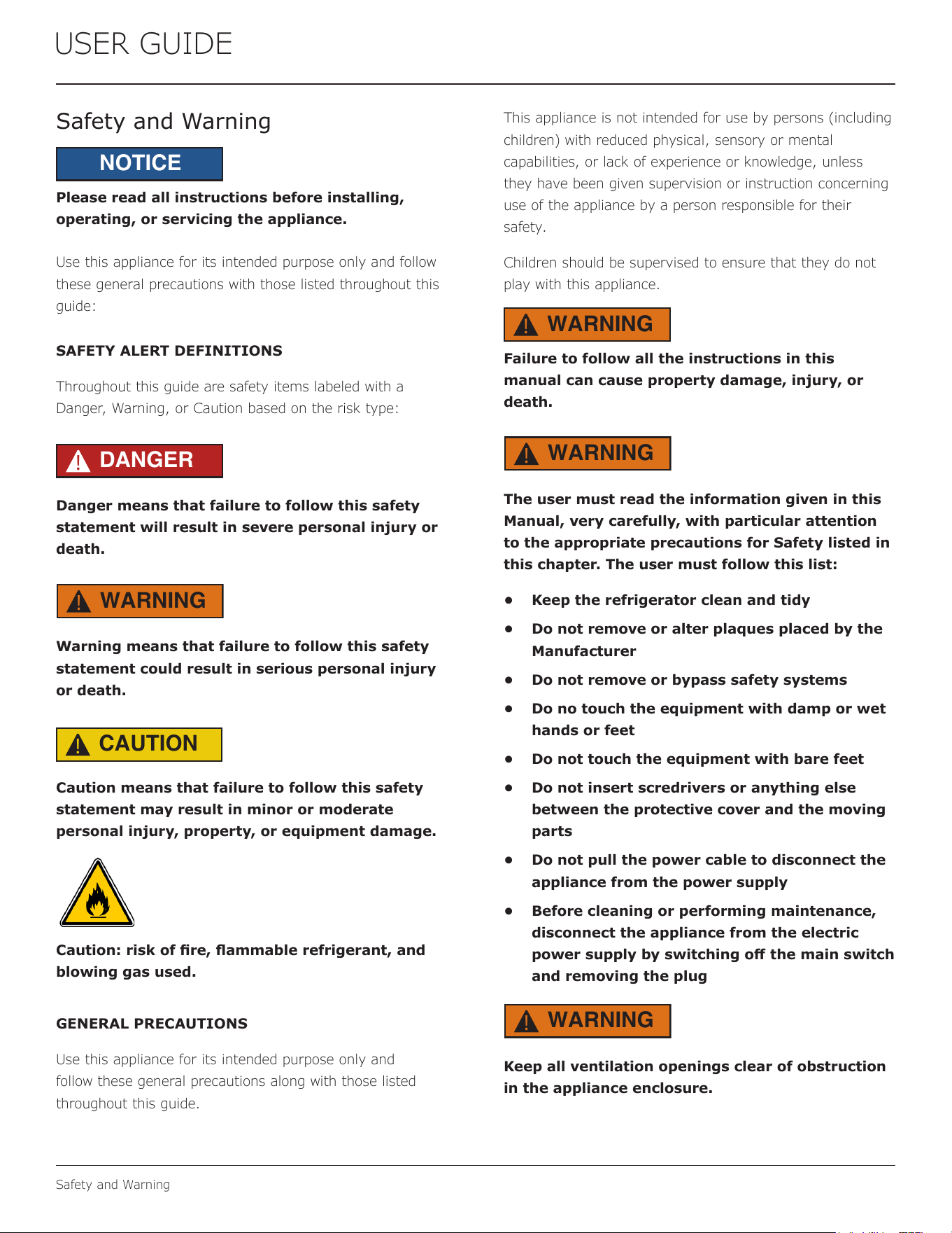
SAFETY ALERT DEFINITIONS
Throughout this guide are safety items labeled with a
Danger, Warning, or Caution based on the risk type:
DANGER
!
Danger means that failure to follow this safety
statement will result in severe personal injury or
death.
WARNING
!
Warning means that failure to follow this safety
statement could result in serious personal injury
or death.
CAUTION
!
Caution means that failure to follow this safety
statement may result in minor or moderate
personal injury, property, or equipment damage.
Caution: risk of re, ammable refrigerant, and
blowing gas used.
GENERAL PRECAUTIONS
Use this appliance for its intended purpose only and
follow these general precautions along with those listed
throughout this guide.
This appliance is not intended for use by persons (including
children) with reduced physical, sensory or mental
capabilities, or lack of experience or knowledge, unless
they have been given supervision or instruction concerning
use of the appliance by a person responsible for their
safety.
Children should be supervised to ensure that they do not
play with this appliance.
WARNING
!
Failure to follow all the instructions in this
manual can cause property damage, injury, or
death.
WARNING
!
The user must read the information given in this
Manual, very carefully, with particular attention
to the appropriate precautions for Safety listed in
this chapter. The user must follow this list:
• Keep the refrigerator clean and tidy
• Do not remove or alter plaques placed by the
Manufacturer
• Do not remove or bypass safety systems
• Do no touch the equipment with damp or wet
hands or feet
• Do not touch the equipment with bare feet
• Do not insert scredrivers or anything else
between the protective cover and the moving
parts
• Do not pull the power cable to disconnect the
appliance from the power supply
• Before cleaning or performing maintenance,
disconnect the appliance from the electric
power supply by switching o the main switch
and removing the plug
WARNING
!
Keep all ventilation openings clear of obstruction
in the appliance enclosure.
4
USER GUIDE
Safety and Warning
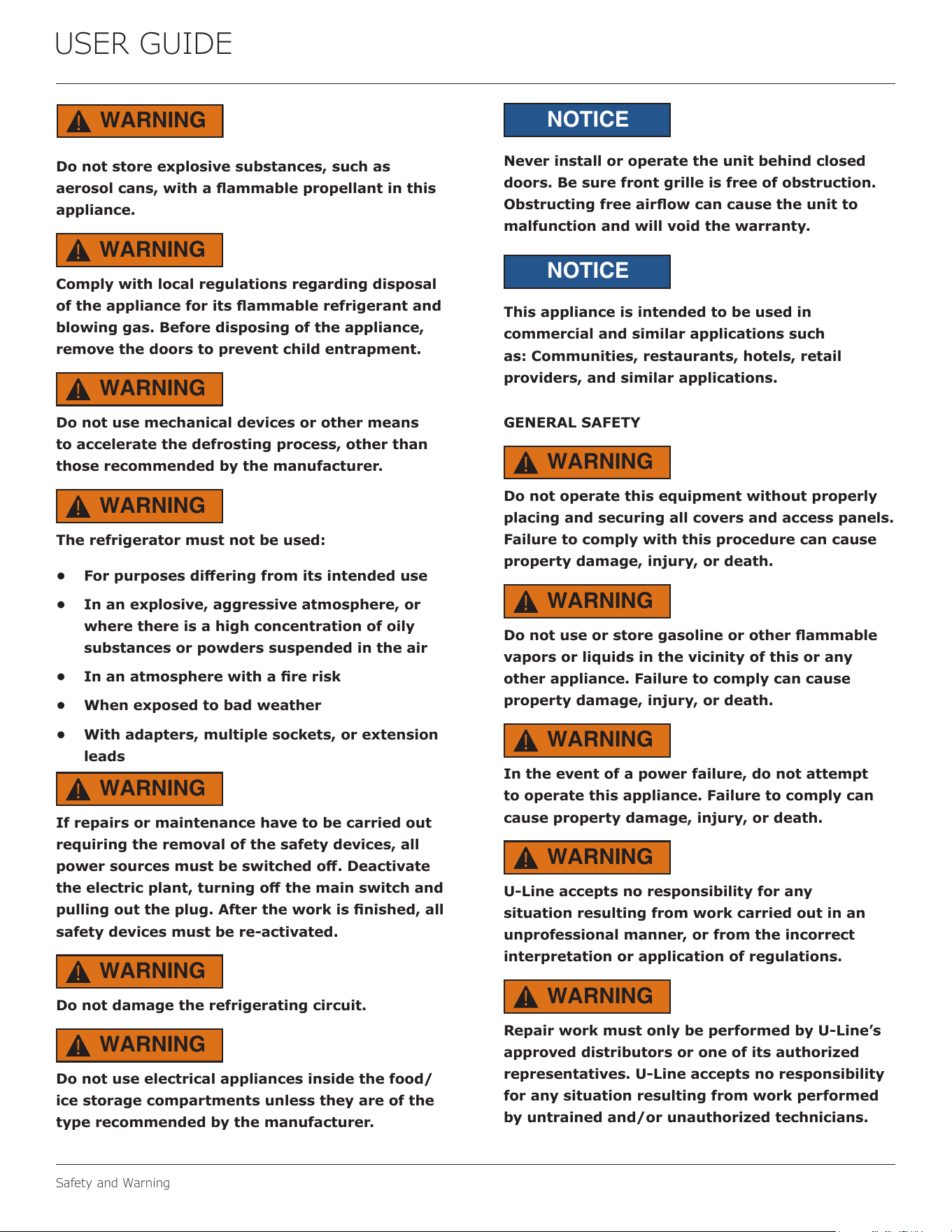
WARNING
!
Do not store explosive substances, such as
aerosol cans, with a ammable propellant in this
appliance.
WARNING
!
Comply with local regulations regarding disposal
of the appliance for its ammable refrigerant and
blowing gas. Before disposing of the appliance,
remove the doors to prevent child entrapment.
WARNING
!
Do not use mechanical devices or other means
to accelerate the defrosting process, other than
those recommended by the manufacturer.
WARNING
!
The refrigerator must not be used:
• For purposes diering from its intended use
• In an explosive, aggressive atmosphere, or
where there is a high concentration of oily
substances or powders suspended in the air
• In an atmosphere with a re risk
• When exposed to bad weather
• With adapters, multiple sockets, or extension
leads
WARNING
!
If repairs or maintenance have to be carried out
requiring the removal of the safety devices, all
power sources must be switched o. Deactivate
the electric plant, turning o the main switch and
pulling out the plug. After the work is nished, all
safety devices must be re-activated.
WARNING
!
Do not damage the refrigerating circuit.
WARNING
!
Do not use electrical appliances inside the food/
ice storage compartments unless they are of the
type recommended by the manufacturer.
NOTICE
Never install or operate the unit behind closed
doors. Be sure front grille is free of obstruction.
Obstructing free airow can cause the unit to
malfunction and will void the warranty.
NOTICE
This appliance is intended to be used in
commercial and similar applications such
as: Communities, restaurants, hotels, retail
providers, and similar applications.
GENERAL SAFETY
WARNING
!
Do not operate this equipment without properly
placing and securing all covers and access panels.
Failure to comply with this procedure can cause
property damage, injury, or death.
WARNING
!
Do not use or store gasoline or other ammable
vapors or liquids in the vicinity of this or any
other appliance. Failure to comply can cause
property damage, injury, or death.
WARNING
!
In the event of a power failure, do not attempt
to operate this appliance. Failure to comply can
cause property damage, injury, or death.
WARNING
!
U-Line accepts no responsibility for any
situation resulting from work carried out in an
unprofessional manner, or from the incorrect
interpretation or application of regulations.
WARNING
!
Repair work must only be performed by U-Line’s
approved distributors or one of its authorized
representatives. U-Line accepts no responsibility
for any situation resulting from work performed
by untrained and/or unauthorized technicians.
5
USER GUIDE
Disposal and Recycling
Disposal and Recycling
RISK OF CHILD ENTRAPMENT. Before you throw
away your old refrigerator or freezer, take o
the doors and leave shelves in place so children
may not easily climb inside.
If the unit is being removed from service for disposal,
check and obey all federal, state, and local regulations
regarding the disposal and recycling of refrigeration
appliances, and follow these steps completely:
1. Remove all consumable contents from the unit.
2. Unplug the electrical cord from its socket.
3. Remove the door(s)/drawer(s).
DANGER
!
6
USER GUIDE
Environmental Requirements
Environmental Requirements
This unit is designed to operate between 45°F (7°C)
and 77°F (25°C). For example, this unit will be eective
whether you operate it in a cold room or hot kitchen.
Higher ambient temperatures may reduce the unit’s ability
to reach low temperatures.
For best performance, keep the unit out of direct sunlight
and away from heat generating equipment.
In climates where high humidity and dew points are
present, condensation may appear on outside surfaces.
This is considered normal. The condensation will evaporate
when the humidity drops.
CAUTION
!
Damages caused by ambient temperatures of
40°F (4°C) or below are not covered by the
warranty.
7
USER GUIDE
Electrical
Electrical
ELECTRICAL WARNINGS
WARNING
!
Never remove the round grounding prong from
the plug and never use a two-prong grounding
adapter.
WARNING
!
Altering, cutting or removing power cord,
removing power plug, or direct wiring can cause
serious injury, re, loss of property and/or life,
and will void the warranty.
WARNING
!
Never use an extension cord to connect power to
the unit.
WARNING
!
Always keep your working area dry.
WARNING
!
Electrical connections should be performed
only by a certied professional. Electrical and
grounding connections must comply with the
applicable portions of the National Electric Code
and/or all local electric codes. Failure to comply
with this procedure can cause property damage,
injury, or death.
WARNING
!
Make sure all facility electrical connections
comply with all local and federal electrical code
regulations.
WARNING
!
Electrical connections or any work required on
the electrical circuits inside the appliance must be
performed by certied technicians in compliance
with local, state, and federal regulations.
WARNING
!
Before connecting the unit to the electrical
supply, verify that the electrical and grounding
connections comply with the applicable portions
of the National Electric Code and/or other local
electrical codes. Failure to comply with this
procedure can cause property damage, injury, or
death.
WARNING
!
Before connecting the unit to the electrical
supply, verify that the electrical connection
agrees with the specications on the data plate.
Failure to comply with this procedure can cause
property damage, injury, or death.
WARNING
!
Appliance must be connected to a grounded,
metal, permanent wiring system. Or an
equipment-grounding conductor must be run
with the circuit conductors and connected to the
equipment-grounding terminal or lead on the
appliance. Failure to comply with this procedure
can cause property damage, injury, or death.
WARNING
!
Appliances equipped with a exible electric
supply cord, are provided with a three-prong
grounding plug. This plug must be connected
into a properly grounded three-prong receptacle.
Failure to comply with this procedure can cause
property damage, injury, or death.
WARNING
!
If the receptacle is not the proper grounding
type, contact an electrician. Do not remove the
grounding prong from the plug. Failure to comply
with this procedure can cause property damage,
injury, or death.
NOTICE
Electrical installation must observe all state and
local codes. This unit requires connection to a
grounded (three-prong), polarized receptacle that
has been placed by a qualied electrician.
8
USER GUIDE
Electrical
ELECTRICAL LOCKOUT/TAGOUT PROCEDURE
WARNING
!
Before removing any sheet metal panels,
always perform the Electrical LOCKOUT/TAGOUT
Procedure. Be sure all circuits are disconnected.
Failure to comply with this procedure can cause
property damage, injury, or death.
WARNING
!
Before performing any service that involves
electrical connection or disconnection and/or
exposure to electrical components, always follow
the Electrical LOCKOUT/TAGOUT Procedure.
Disconnect all circuits. Failure to comply can
cause property damage, injury or death.
The Electrical LOCKOUT/TAGOUT Procedure
is used to protect personnel working on an
electrical appliance. Before performing any
maintenance or service that requires exposure to
electrical components, follow these steps:
1. In electrical box, place appliance circuit
breaker into OFF position.
2. Place a lock or other device on electrical box
cover to prevent someone from placing circuit
breaker ON.
3. Place a tag on electrical box cover to indicate
that appliance has been disconnected for
service and power should not be restored
until tag is removed by maintenance
personnel.
4. Disconnect appliance power cord from
electrical outlet.
5. Place a tag on the cord to indicate that unit
has been disconnected for service and power
should not be restored until tag is removed by
maintenance personnel.
The unit requires a grounded and polarized 208 – 220 VAC,
60 Hz, 30A power supply (normal household current).
An individual, properly grounded branch circuit or circuit
breaker is recommended. A GFCI (ground fault circuit
interrupter) is usually not required for xed location
appliances and is not recommended for your unit because
it could be prone to nuisance tripping. However, be sure to
consult your local codes.
See CUTOUT & PRODUCT DIMENSIONS for recommended
receptacle location.
9
USER GUIDE
General Installation
General Installation
ASSEMBLE THE UNIT
TO PREVENT DAMAGING THE PANELS OR
PERSONAL INJURY, DO NOT ATTEMPT ASSEMBLY
WITHOUT THE HELP OF AT LEAST TWO OTHER
PEOPLE.
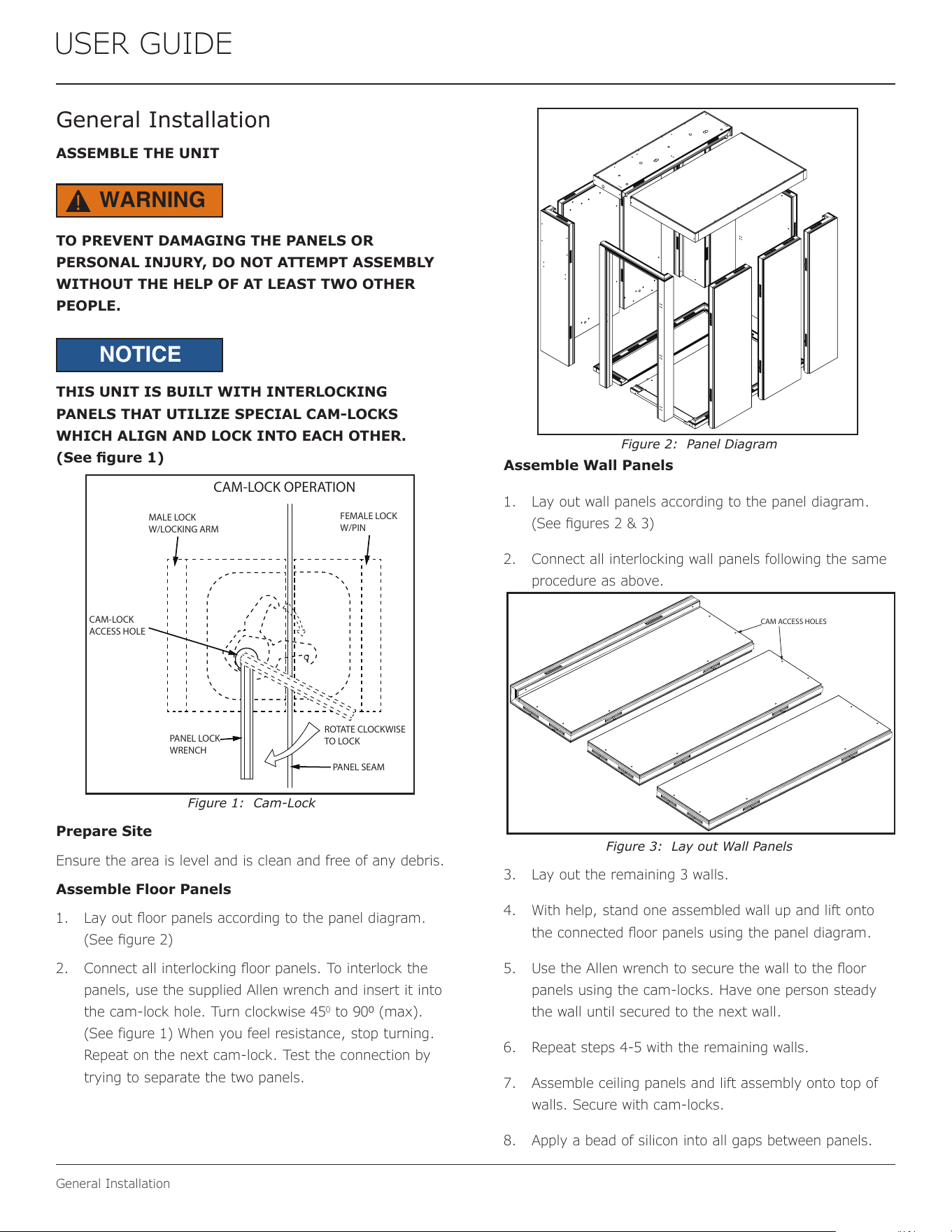
THIS UNIT IS BUILT WITH INTERLOCKING
PANELS THAT UTILIZE SPECIAL CAM-LOCKS
WHICH ALIGN AND LOCK INTO EACH OTHER.
(See gure 1)
Figure 1: Cam-Lock
Prepare Site
Ensure the area is level and is clean and free of any debris.
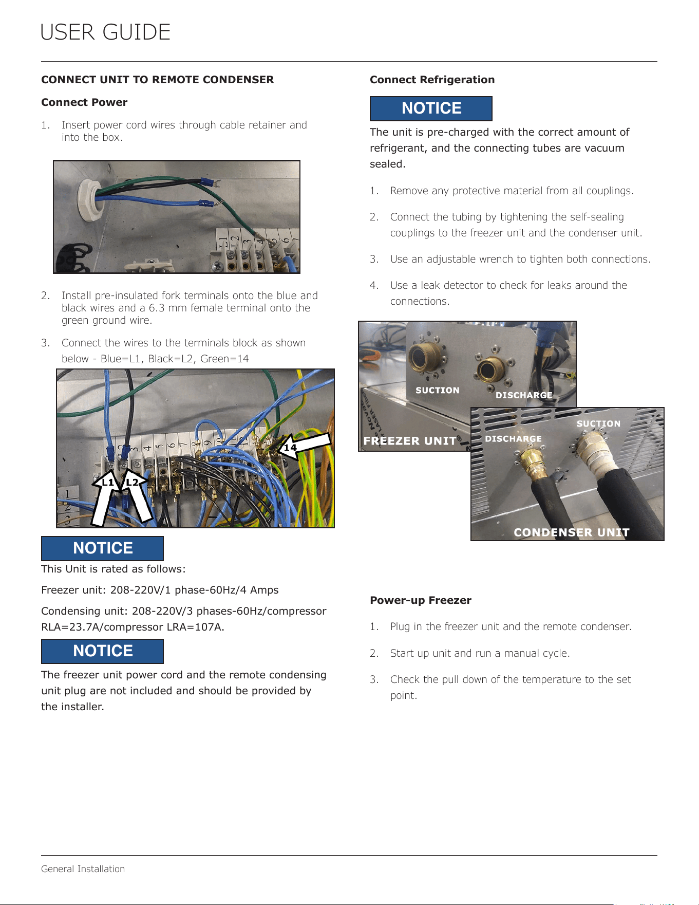
Assemble Floor Panels
1. Lay out oor panels according to the panel diagram.
(See gure 2)
2. Connect all interlocking oor panels. To interlock the
panels, use the supplied Allen wrench and insert it into
the cam-lock hole. Turn clockwise 45
0
to 900 (max).
(See figure 1) When you feel resistance, stop turning.
Repeat on the next cam-lock. Test the connection by
trying to separate the two panels.
Figure 2: Panel Diagram
Assemble Wall Panels
1. Lay out wall panels according to the panel diagram.
(See gures 2 & 3)
2. Connect all interlocking wall panels following the same
procedure as above.
Figure 3: Lay out Wall Panels
3. Lay out the remaining 3 walls.
4. With help, stand one assembled wall up and lift onto
the connected oor panels using the panel diagram.
5. Use the Allen wrench to secure the wall to the oor
panels using the cam-locks. Have one person steady
the wall until secured to the next wall.
6. Repeat steps 4-5 with the remaining walls.
7. Assemble ceiling panels and lift assembly onto top of
walls. Secure with cam-locks.
8. Apply a bead of silicon into all gaps between panels.
ROTATE CLOCKWISE
TO LOCK
PANEL LOCK
WRENCH
PANEL SEAM
FEMALE LOCK
W/PIN
MALE LOCK
W/LOCKING ARM
CAM-LOCK
ACCESS HOLE
CAM-LOCK OPERATION
CAM ACCESS HOLES
WARNING
!
NOTICE
10
USER GUIDE
General Installation
CONNECT UNIT TO REMOTE CONDENSER
Connect Power
1. Insert power cord wires through cable retainer and
into the box.
2. Install pre-insulated fork terminals onto the blue and
black wires and a 6.3 mm female terminal onto the
green ground wire.
3. Connect the wires to the terminals block as shown
below - Blue=L1, Black=L2, Green=14
This Unit is rated as follows:
Freezer unit: 208-220V/1 phase-60Hz/4 Amps
Condensing unit: 208-220V/3 phases-60Hz/compressor
RLA=23.7A/compressor LRA=107A.
The freezer unit power cord and the remote condensing
unit plug are not included and should be provided by
the installer.
Connect Refrigeration
The unit is pre-charged with the correct amount of
refrigerant, and the connecting tubes are vacuum
sealed.
1. Remove any protective material from all couplings.
2. Connect the tubing by tightening the self-sealing
couplings to the freezer unit and the condenser unit.
3. Use an adjustable wrench to tighten both connections.
4. Use a leak detector to check for leaks around the
connections.
Power-up Freezer
1. Plug in the freezer unit and the remote condenser.
2. Start up unit and run a manual cycle.
3. Check the pull down of the temperature to the set
point.
NOTICE
NOTICE
NOTICE
11
USER GUIDE
Control Operation
Control Operation
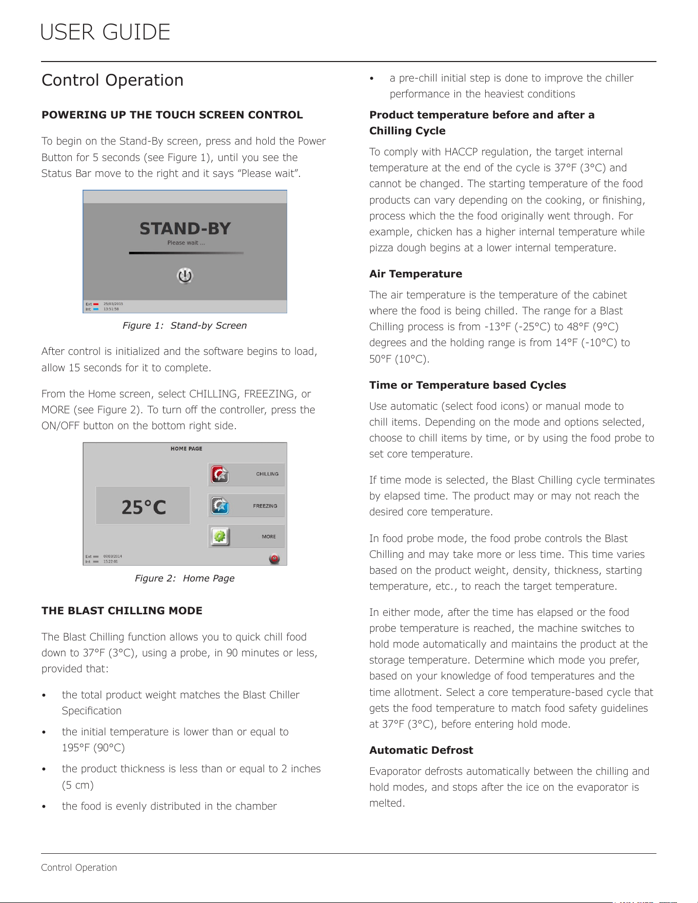
POWERING UP THE TOUCH SCREEN CONTROL
To begin on the Stand-By screen, press and hold the Power
Button for 5 seconds (see Figure 1), until you see the
Status Bar move to the right and it says “Please wait”.
Figure 1: Stand-by Screen
After control is initialized and the software begins to load,
allow 15 seconds for it to complete.
From the Home screen, select CHILLING, FREEZING, or
MORE (see Figure 2). To turn o the controller, press the
ON/OFF button on the bottom right side.
Figure 2: Home Page
THE BLAST CHILLING MODE
The Blast Chilling function allows you to quick chill food
down to 37°F (3°C), using a probe, in 90 minutes or less,
provided that:
• the total product weight matches the Blast Chiller
Specication
• the initial temperature is lower than or equal to
195°F (90°C)
• the product thickness is less than or equal to 2 inches
(5 cm)
• the food is evenly distributed in the chamber
• a pre-chill initial step is done to improve the chiller
performance in the heaviest conditions
Product temperature before and after a
Chilling Cycle
To comply with HACCP regulation, the target internal
temperature at the end of the cycle is 37°F (3°C) and
cannot be changed. The starting temperature of the food
products can vary depending on the cooking, or nishing,
process which the the food originally went through. For
example, chicken has a higher internal temperature while
pizza dough begins at a lower internal temperature.
Air Temperature
The air temperature is the temperature of the cabinet
where the food is being chilled. The range for a Blast
Chilling process is from -13°F (-25°C) to 48°F (9°C)
degrees and the holding range is from 14°F (-10°C) to
50°F (10°C).
Time or Temperature based Cycles
Use automatic (select food icons) or manual mode to
chill items. Depending on the mode and options selected,
choose to chill items by time, or by using the food probe to
set core temperature.
If time mode is selected, the Blast Chilling cycle terminates
by elapsed time. The product may or may not reach the
desired core temperature.
In food probe mode, the food probe controls the Blast
Chilling and may take more or less time. This time varies
based on the product weight, density, thickness, starting
temperature, etc., to reach the target temperature.
In either mode, after the time has elapsed or the food
probe temperature is reached, the machine switches to
hold mode automatically and maintains the product at the
storage temperature. Determine which mode you prefer,
based on your knowledge of food temperatures and the
time allotment. Select a core temperature-based cycle that
gets the food temperature to match food safety guidelines
at 37°F (3°C), before entering hold mode.
Automatic Defrost
Evaporator defrosts automatically between the chilling and
hold modes, and stops after the ice on the evaporator is
melted.
12
USER GUIDE
Control Operation
Blast Chilling Cycle Activation
When CHILLING mode is selected, the machine
automatically pre-chills the cabinet to 23°F (-5°C) (see
Figure 2). After reaching the pre-chill temperature, the
manual cycle, or recipe, can be started.
Press the green arrow (Play) to go directly to the recipe
selection screen and skip the pre-chill cycle.
Figure 3: Pre-chilling Screen
Select the appropriate food category or manual cycle.
Figure 4: Food Categories Available
Blast Chilling Automatic OEM Recipes
The pre-programmed recipes do not require cycle setting.
These recipes come with pre-determined settings that give
the best chilling process for the selected type of food (see
Figure 4).
Every recipe has four categories to suit variations of the
selected food.
Figure 5: Meat Chilling Recipe Options
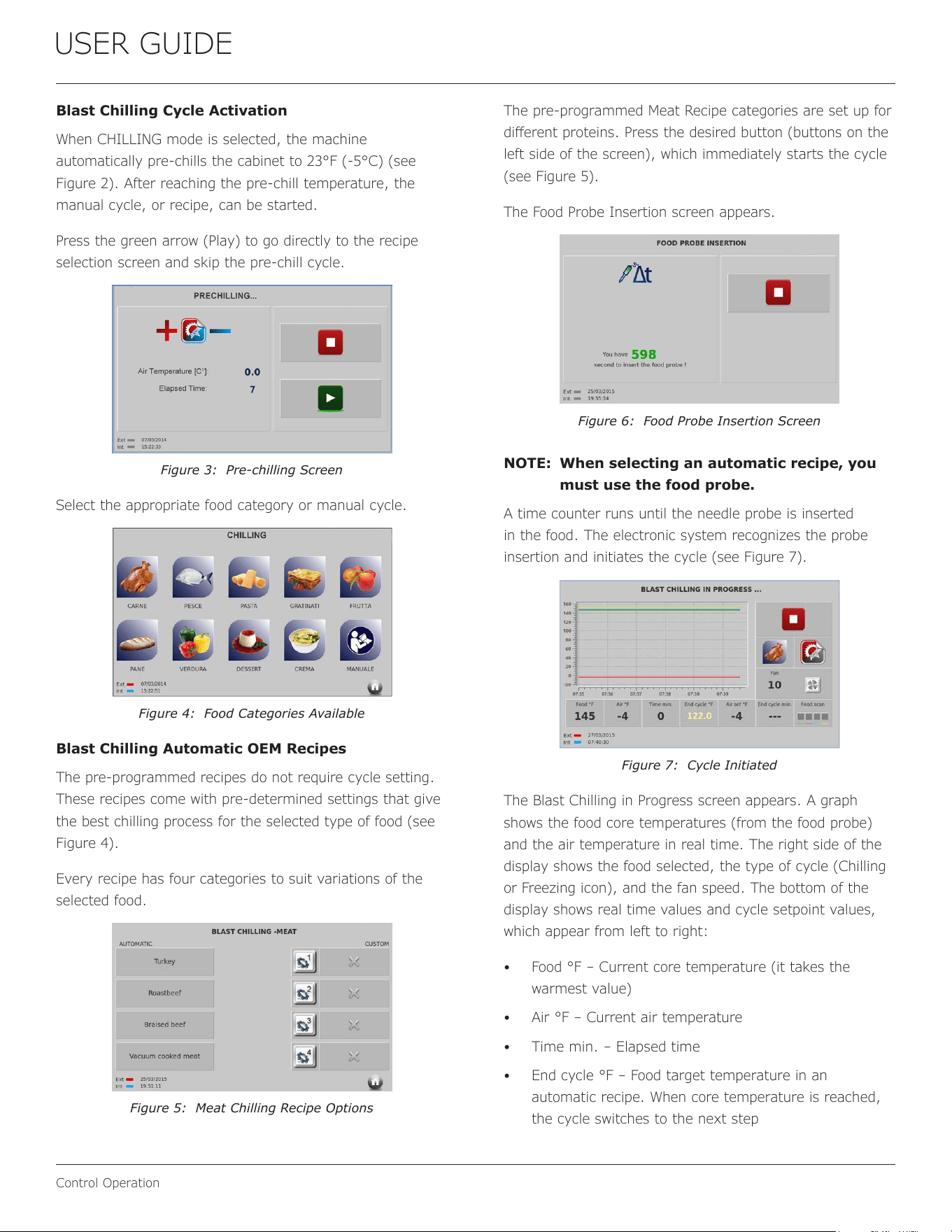
The pre-programmed Meat Recipe categories are set up for
dierent proteins. Press the desired button (buttons on the
left side of the screen), which immediately starts the cycle
(see Figure 5).
The Food Probe Insertion screen appears.
Figure 6: Food Probe Insertion Screen
NOTE: When selecting an automatic recipe, you
must use the food probe.
A time counter runs until the needle probe is inserted
in the food. The electronic system recognizes the probe
insertion and initiates the cycle (see Figure 7).
Figure 7: Cycle Initiated
The Blast Chilling in Progress screen appears. A graph
shows the food core temperatures (from the food probe)
and the air temperature in real time. The right side of the
display shows the food selected, the type of cycle (Chilling
or Freezing icon), and the fan speed. The bottom of the
display shows real time values and cycle setpoint values,
which appear from left to right:
• Food °F – Current core temperature (it takes the
warmest value)
• Air °F – Current air temperature
• Time min. – Elapsed time
• End cycle °F – Food target temperature in an
automatic recipe. When core temperature is reached,
the cycle switches to the next step
13
USER GUIDE
Control Operation
• Air set °F – Desired air temperature of the current step
• End cycle min. – Time the cycle will end (e.g., three
dashes indicates a core temperature-based cycle, so
time is not available)
• Food scan – Status of the four core temperatures.
The system monitors the four cores of the food thickness
in the rst ve minutes of the cycle. Cores can be excluded
from the algorithm, which means the food measured with
the excluded will not be measured. The warmest core will
determine the end of the total cycle 37°F (3°C). Each core
contributes to regulate the internal cycle’s steps, varying
the air set temperature and fan speed. The following
indicators show core status:
• Blue – Warmest core
• Green – Core is positioned in the food thickness
• Grey – Excluded core
While scanning the food, the cycle runs through four
steps with dierent settings. The goal is to chill the food
in the shortest possible time, while saving the product
integrity. For example, a piece of cooked meat with an
internal temperature of 90°C (194°F) runs through the
initial step at very low temperature. The meat reaches the
highest air temperature at the end to prevent freezer burn.
Conversely, bread is chilled at a warmer air temperature
(above the freezing point) from the start, in order to not
aect the product surface.
NOTE: Automatic OEM recipes are set up in
the factory and guarantee the best
combination of steps for a chilling cycle.
Blast Chilling Manual Program
Press the Manual button on the Food Selection screen (see
Figure 4).
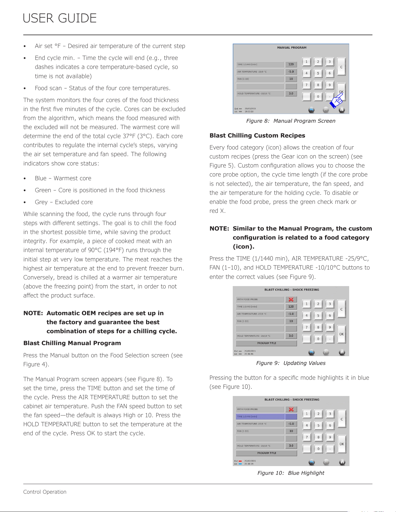
The Manual Program screen appears (see Figure 8). To
set the time, press the TIME button and set the time of
the cycle. Press the AIR TEMPERATURE button to set the
cabinet air temperature. Push the FAN speed button to set
the fan speed—the default is always High or 10. Press the
HOLD TEMPERATURE button to set the temperature at the
end of the cycle. Press OK to start the cycle.
Figure 8: Manual Program Screen
Blast Chilling Custom Recipes
Every food category (icon) allows the creation of four
custom recipes (press the Gear icon on the screen) (see
Figure 5). Custom conguration allows you to choose the
core probe option, the cycle time length (if the core probe
is not selected), the air temperature, the fan speed, and
the air temperature for the holding cycle. To disable or
enable the food probe, press the green check mark or
red X.
NOTE: Similar to the Manual Program, the custom
conguration is related to a food category
(icon).
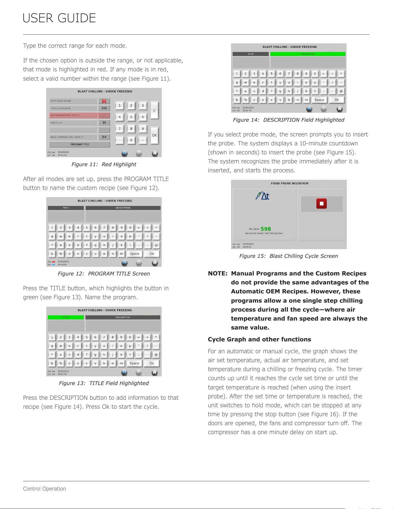
Press the TIME (1/1440 min), AIR TEMPERATURE -25/9°C,
FAN (1–10), and HOLD TEMPERATURE -10/10°C buttons to
enter the correct values (see Figure 9).
Figure 9: Updating Values
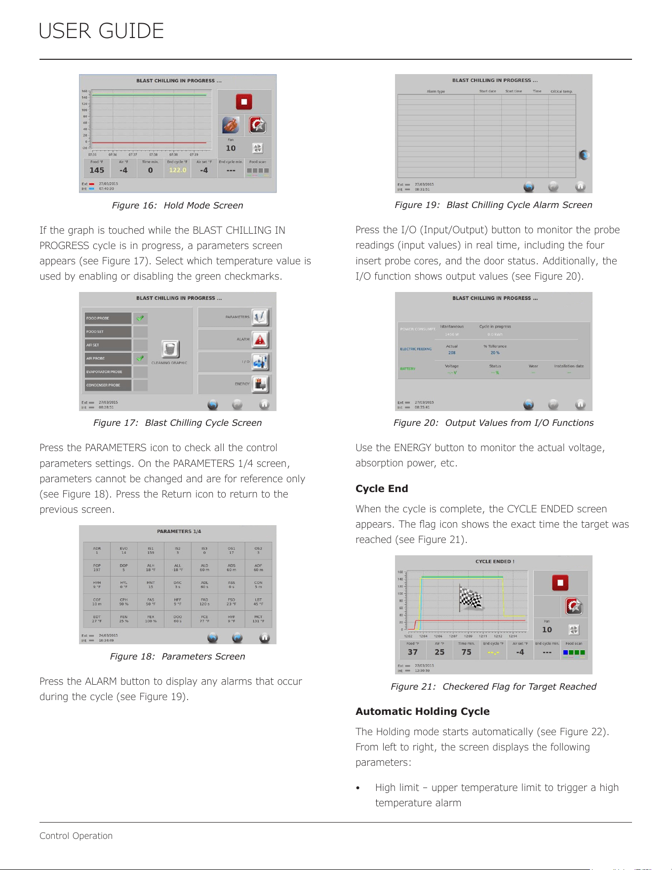
Pressing the button for a specic mode highlights it in blue
(see Figure 10).
Figure 10: Blue Highlight
14
USER GUIDE
Control Operation
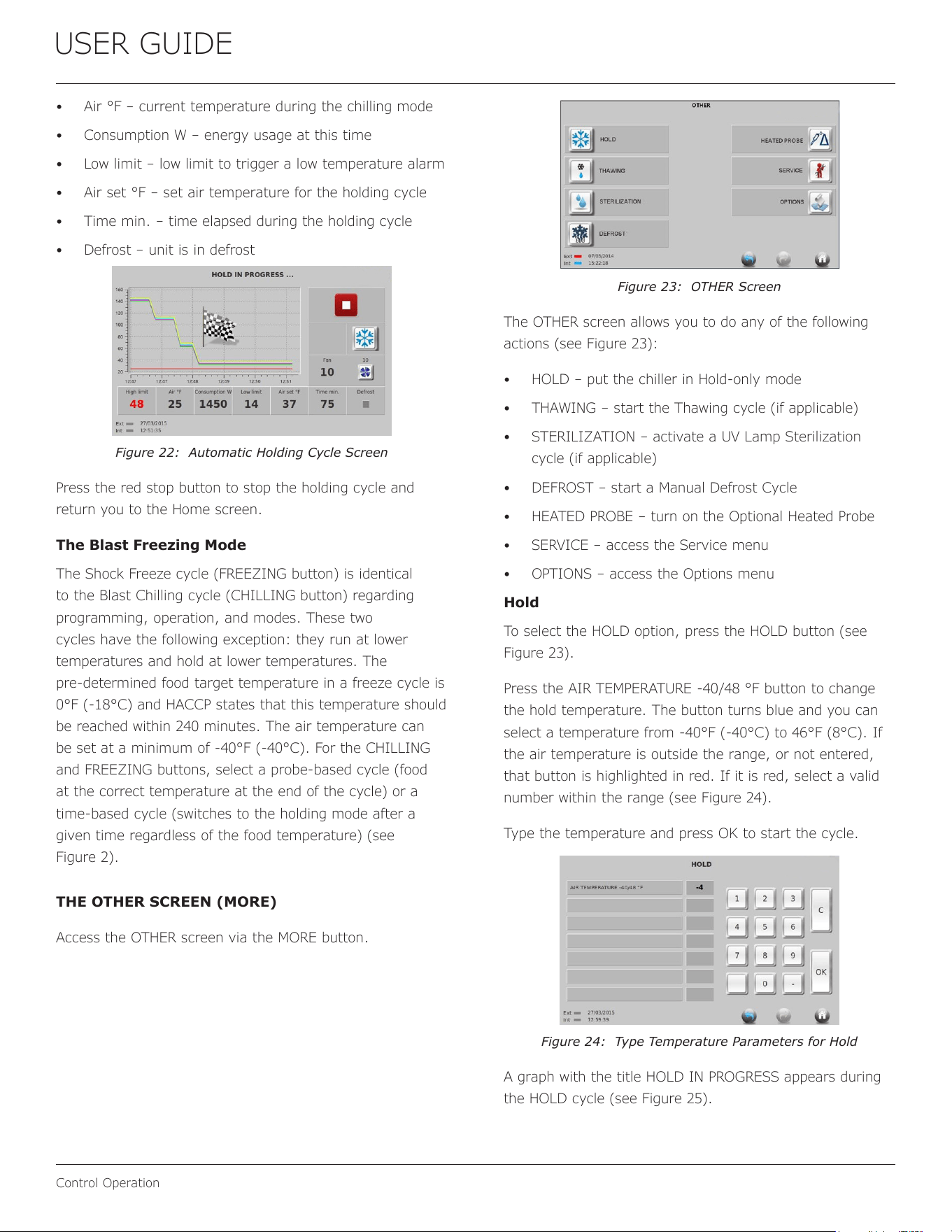
Type the correct range for each mode.
If the chosen option is outside the range, or not applicable,
that mode is highlighted in red. If any mode is in red,
select a valid number within the range (see Figure 11).
Figure 11: Red Highlight
After all modes are set up, press the PROGRAM TITLE
button to name the custom recipe (see Figure 12).
Figure 12: PROGRAM TITLE Screen
Press the TITLE button, which highlights the button in
green (see Figure 13). Name the program.
Figure 13: TITLE Field Highlighted
Press the DESCRIPTION button to add information to that
recipe (see Figure 14). Press Ok to start the cycle.
Figure 14: DESCRIPTION Field Highlighted
If you select probe mode, the screen prompts you to insert
the probe. The system displays a 10-minute countdown
(shown in seconds) to insert the probe (see Figure 15).
The system recognizes the probe immediately after it is
inserted, and starts the process.
Figure 15: Blast Chilling Cycle Screen
NOTE: Manual Programs and the Custom Recipes
do not provide the same advantages of the
Automatic OEM Recipes. However, these
programs allow a one single step chilling
process during all the cycle—where air
temperature and fan speed are always the
same value.
Cycle Graph and other functions
For an automatic or manual cycle, the graph shows the
air set temperature, actual air temperature, and set
temperature during a chilling or freezing cycle. The timer
counts up until it reaches the cycle set time or until the
target temperature is reached (when using the insert
probe). After the set time or temperature is reached, the
unit switches to hold mode, which can be stopped at any
time by pressing the stop button (see Figure 16). If the
doors are opened, the fans and compressor turn o. The
compressor has a one minute delay on start up.
15
USER GUIDE
Control Operation
Figure 16: Hold Mode Screen
If the graph is touched while the BLAST CHILLING IN
PROGRESS cycle is in progress, a parameters screen
appears (see Figure 17). Select which temperature value is
used by enabling or disabling the green checkmarks.
Figure 17: Blast Chilling Cycle Screen
Press the PARAMETERS icon to check all the control
parameters settings. On the PARAMETERS 1/4 screen,
parameters cannot be changed and are for reference only
(see Figure 18). Press the Return icon to return to the
previous screen.
Figure 18: Parameters Screen
Press the ALARM button to display any alarms that occur
during the cycle (see Figure 19).
Figure 19: Blast Chilling Cycle Alarm Screen
Press the I/O (Input/Output) button to monitor the probe
readings (input values) in real time, including the four
insert probe cores, and the door status. Additionally, the
I/O function shows output values (see Figure 20).
Figure 20: Output Values from I/O Functions
Use the ENERGY button to monitor the actual voltage,
absorption power, etc.
Cycle End
When the cycle is complete, the CYCLE ENDED screen
appears. The ag icon shows the exact time the target was
reached (see Figure 21).
Figure 21: Checkered Flag for Target Reached
Automatic Holding Cycle
The Holding mode starts automatically (see Figure 22).
From left to right, the screen displays the following
parameters:
• High limit – upper temperature limit to trigger a high
temperature alarm
16
USER GUIDE
Control Operation
• Air °F – current temperature during the chilling mode
• Consumption W – energy usage at this time
• Low limit – low limit to trigger a low temperature alarm
• Air set °F – set air temperature for the holding cycle
• Time min. – time elapsed during the holding cycle
• Defrost – unit is in defrost
Figure 22: Automatic Holding Cycle Screen
Press the red stop button to stop the holding cycle and
return you to the Home screen.
The Blast Freezing Mode
The Shock Freeze cycle (FREEZING button) is identical
to the Blast Chilling cycle (CHILLING button) regarding
programming, operation, and modes. These two
cycles have the following exception: they run at lower
temperatures and hold at lower temperatures. The
pre-determined food target temperature in a freeze cycle is
0°F (-18°C) and HACCP states that this temperature should
be reached within 240 minutes. The air temperature can
be set at a minimum of -40°F (-40°C). For the CHILLING
and FREEZING buttons, select a probe-based cycle (food
at the correct temperature at the end of the cycle) or a
time-based cycle (switches to the holding mode after a
given time regardless of the food temperature) (see
Figure 2).
THE OTHER SCREEN (MORE)
Access the OTHER screen via the MORE button.
Figure 23: OTHER Screen
The OTHER screen allows you to do any of the following
actions (see Figure 23):
• HOLD – put the chiller in Hold-only mode
• THAWING – start the Thawing cycle (if applicable)
• STERILIZATION – activate a UV Lamp Sterilization
cycle (if applicable)
• DEFROST – start a Manual Defrost Cycle
• HEATED PROBE – turn on the Optional Heated Probe
• SERVICE – access the Service menu
• OPTIONS – access the Options menu
Hold
To select the HOLD option, press the HOLD button (see
Figure 23).
Press the AIR TEMPERATURE -40/48 °F button to change
the hold temperature. The button turns blue and you can
select a temperature from -40°F (-40°C) to 46°F (8°C). If
the air temperature is outside the range, or not entered,
that button is highlighted in red. If it is red, select a valid
number within the range (see Figure 24).
Type the temperature and press OK to start the cycle.
Figure 24: Type Temperature Parameters for Hold
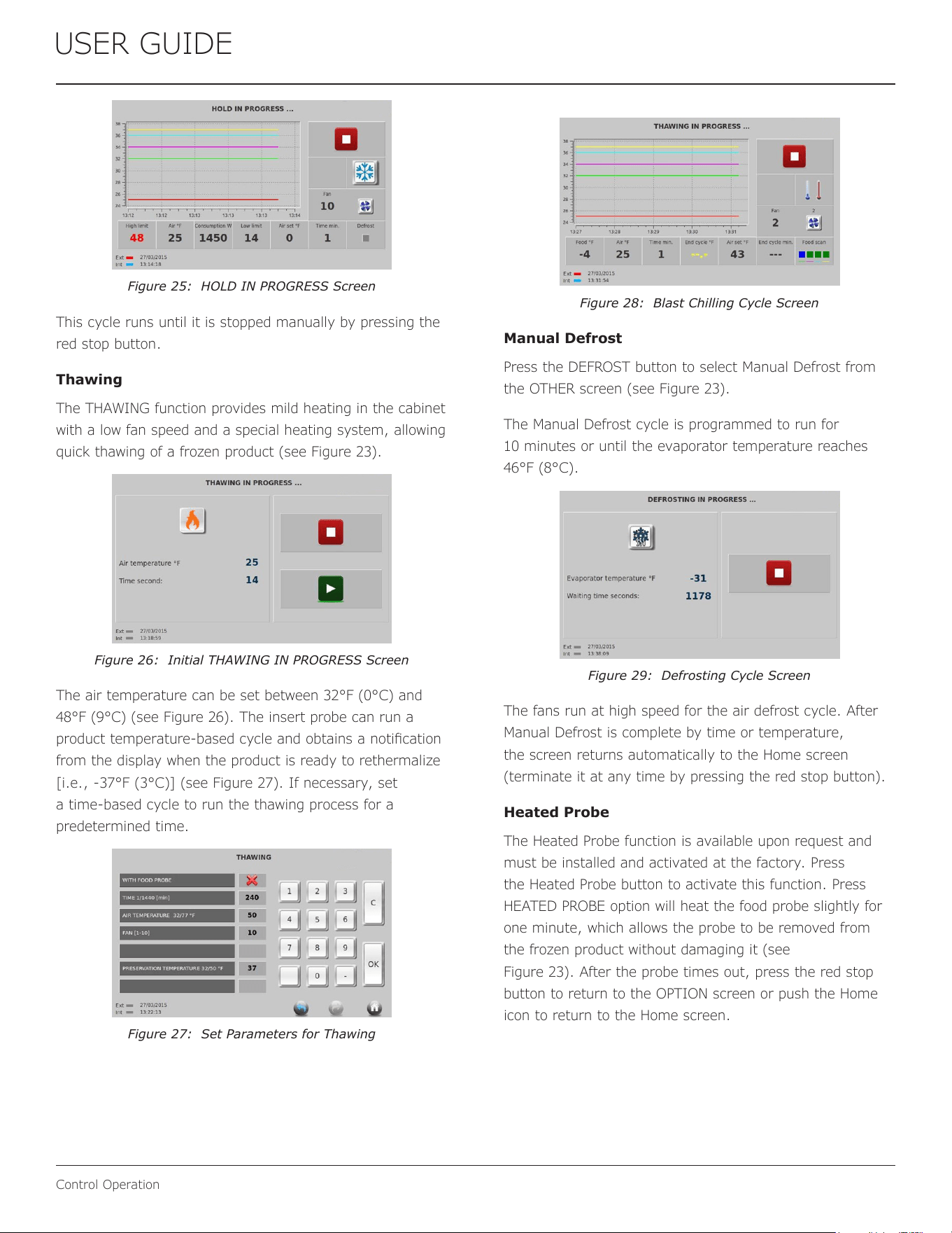
A graph with the title HOLD IN PROGRESS appears during
the HOLD cycle (see Figure 25).
17
USER GUIDE
Control Operation
Figure 25: HOLD IN PROGRESS Screen
This cycle runs until it is stopped manually by pressing the
red stop button.
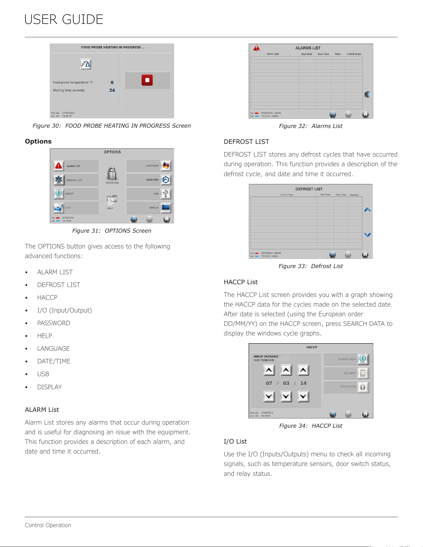
Thawing
The THAWING function provides mild heating in the cabinet
with a low fan speed and a special heating system, allowing
quick thawing of a frozen product (see Figure 23).
Figure 26: Initial THAWING IN PROGRESS Screen
The air temperature can be set between 32°F (0°C) and
48°F (9°C) (see Figure 26). The insert probe can run a
product temperature‑based cycle and obtains a notication
from the display when the product is ready to rethermalize
[i.e., -37°F (3°C)] (see Figure 27). If necessary, set
a time-based cycle to run the thawing process for a
predetermined time.
Figure 27: Set Parameters for Thawing
Figure 28: Blast Chilling Cycle Screen
Manual Defrost
Press the DEFROST button to select Manual Defrost from
the OTHER screen (see Figure 23).
The Manual Defrost cycle is programmed to run for
10 minutes or until the evaporator temperature reaches
46°F (8°C).
Figure 29: Defrosting Cycle Screen
The fans run at high speed for the air defrost cycle. After
Manual Defrost is complete by time or temperature,
the screen returns automatically to the Home screen
(terminate it at any time by pressing the red stop button).
Heated Probe
The Heated Probe function is available upon request and
must be installed and activated at the factory. Press
the Heated Probe button to activate this function. Press
HEATED PROBE option will heat the food probe slightly for
one minute, which allows the probe to be removed from
the frozen product without damaging it (see
Figure 23). After the probe times out, press the red stop
button to return to the OPTION screen or push the Home
icon to return to the Home screen.
18
USER GUIDE
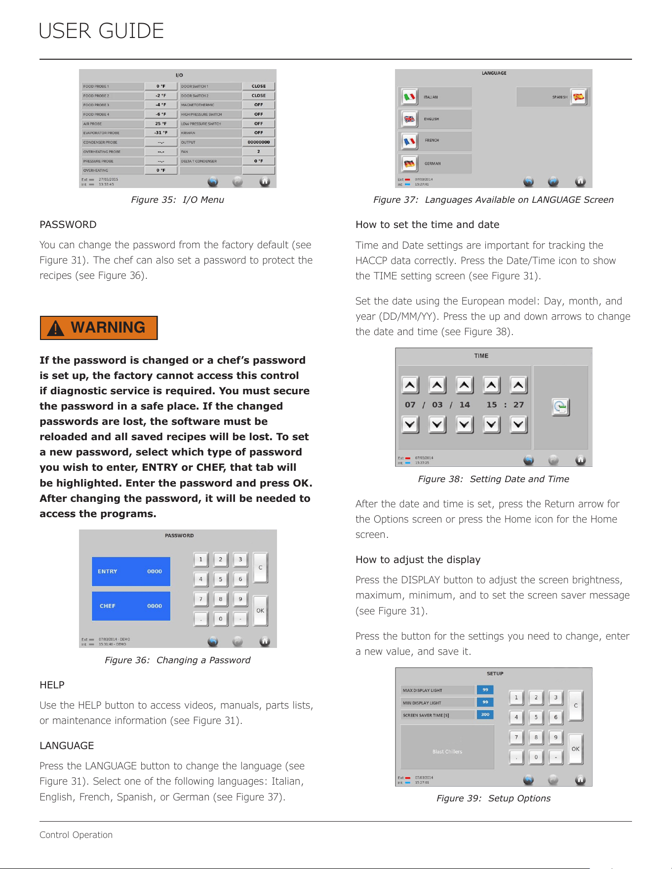
Control Operation
Figure 30: FOOD PROBE HEATING IN PROGRESS Screen
Options
Figure 31: OPTIONS Screen
The OPTIONS button gives access to the following
advanced functions:
• ALARM LIST
• DEFROST LIST
• HACCP
• I/O (Input/Output)
• PASSWORD
• HELP
• LANGUAGE
• DATE/TIME
• USB
• DISPLAY
ALARM List
Alarm List stores any alarms that occur during operation
and is useful for diagnosing an issue with the equipment.
This function provides a description of each alarm, and
date and time it occurred.
Figure 32: Alarms List
DEFROST LIST
DEFROST LIST stores any defrost cycles that have occurred
during operation. This function provides a description of the
defrost cycle, and date and time it occurred.
Figure 33: Defrost List
HACCP List
The HACCP List screen provides you with a graph showing
the HACCP data for the cycles made on the selected date.
After date is selected (using the European order
DD/MM/YY) on the HACCP screen, press SEARCH DATA to
display the windows cycle graphs.
Figure 34: HACCP List
I/O List
Use the I/O (Inputs/Outputs) menu to check all incoming
signals, such as temperature sensors, door switch status,
and relay status.
19
USER GUIDE
Control Operation
Figure 35: I/O Menu
PASSWORD
You can change the password from the factory default (see
Figure 31). The chef can also set a password to protect the
recipes (see Figure 36).
WARNING
!
If the password is changed or a chef’s password
is set up, the factory cannot access this control
if diagnostic service is required. You must secure
the password in a safe place. If the changed
passwords are lost, the software must be
reloaded and all saved recipes will be lost. To set
a new password, select which type of password
you wish to enter, ENTRY or CHEF, that tab will
be highlighted. Enter the password and press OK.
After changing the password, it will be needed to
access the programs.
Figure 36: Changing a Password
HELP
Use the HELP button to access videos, manuals, parts lists,
or maintenance information (see Figure 31).
LANGUAGE
Press the LANGUAGE button to change the language (see
Figure 31). Select one of the following languages: Italian,
English, French, Spanish, or German (see Figure 37).
Figure 37: Languages Available on LANGUAGE Screen
How to set the time and date
Time and Date settings are important for tracking the
HACCP data correctly. Press the Date/Time icon to show
the TIME setting screen (see Figure 31).
Set the date using the European model: Day, month, and
year (DD/MM/YY). Press the up and down arrows to change
the date and time (see Figure 38).
Figure 38: Setting Date and Time
After the date and time is set, press the Return arrow for
the Options screen or press the Home icon for the Home
screen.
How to adjust the display
Press the DISPLAY button to adjust the screen brightness,
maximum, minimum, and to set the screen saver message
(see Figure 31).
Press the button for the settings you need to change, enter
a new value, and save it.
Figure 39: Setup Options
20
USER GUIDE
Control Operation
Press the Return arrow to return to the Options screen, or
press the Home icon to return the Home screen.
USB functions
Access the USB port from behind the sliding panel frame on
the right side of the Touch Screen. Using this port, you can
import and export data to/from a USB stick (see
Figure 40). This type of USB does not require special
hardware; however, an empty formatted USB (ash drive)
with a minimum of 2 Gigabytes is recommended (see
Figure 31).
Figure 40: USB Options
The main active USB functions are:
• Touch Screen Update
• Software Update (only software, only parameter, both
software and parameters)
• Download HACCP Data
DOWNLOAD HACCP DATA AND TRACE CYCLE
DIAGRAMS
This Touch Screen Controller can export HACCP information
to a USB key. Press the related button in the USB menu
and the controller will transfer the data to the USB.
The le will be exported as a zipped le named
“haccp.zip”. When you connect the USB to a PC, the le will
appear as a zipped le in a style similar to those seen in
Figure 41)
Figure 41: Dierent Zipped File Icons Displayed
The icon depends on the zip software installed on the PC.
Use any zip software (such as PKZIP, unzip, winrar, G7,
or similar) to extract the le to a folder (see Figure 41).
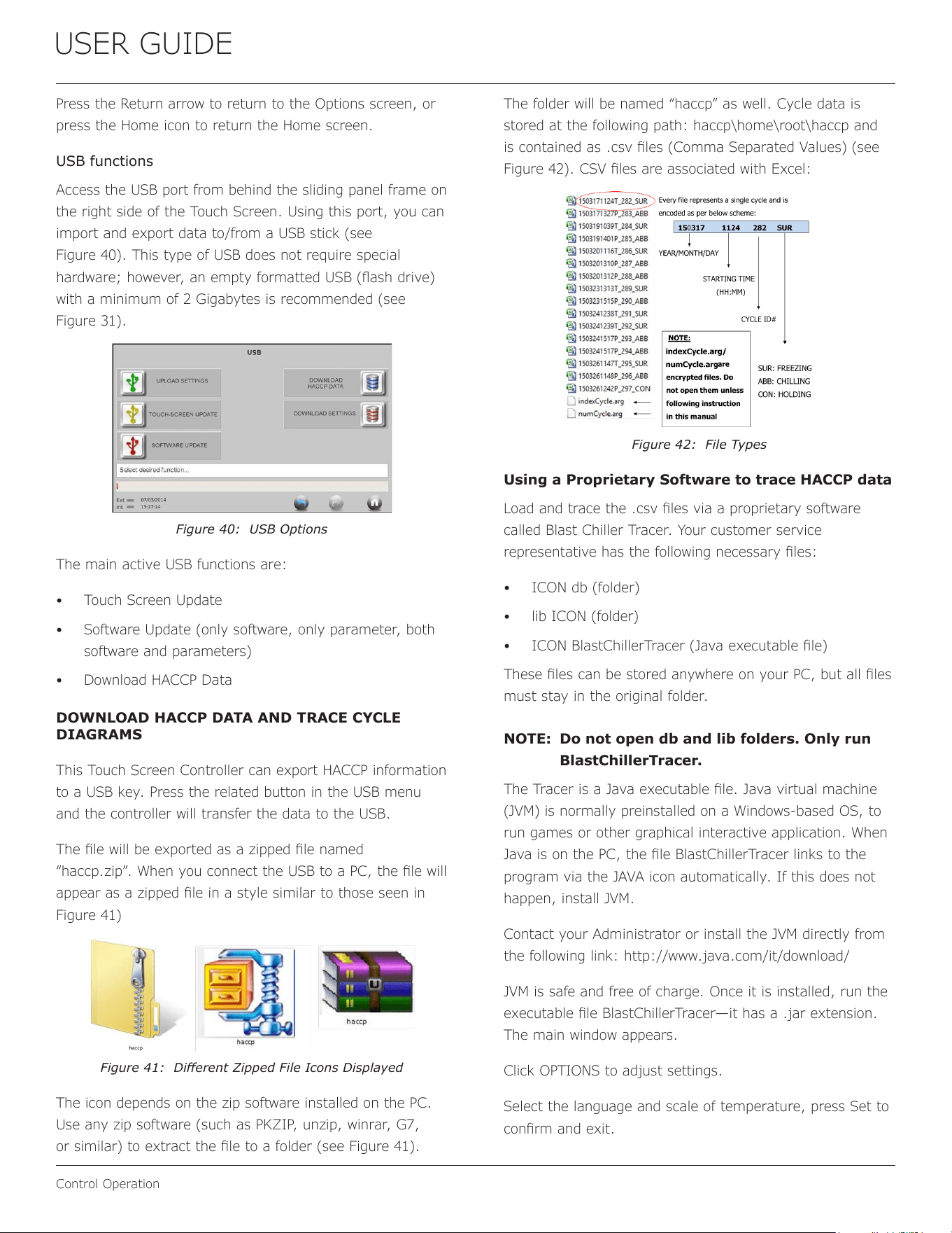
The folder will be named “haccp” as well. Cycle data is
stored at the following path: haccp\home\root\haccp and
is contained as .csv les (Comma Separated Values) (see
Figure 42). CSV les are associated with Excel:
Figure 42: File Types
Using a Proprietary Software to trace HACCP data
Load and trace the .csv les via a proprietary software
called Blast Chiller Tracer. Your customer service
representative has the following necessary les:
• ICON db (folder)
• lib ICON (folder)
• ICON BlastChillerTracer (Java executable le)
These les can be stored anywhere on your PC, but all les
must stay in the original folder.
NOTE: Do not open db and lib folders. Only run
BlastChillerTracer.
The Tracer is a Java executable le. Java virtual machine
(JVM) is normally preinstalled on a Windows-based OS, to
run games or other graphical interactive application. When
Java is on the PC, the le BlastChillerTracer links to the
program via the JAVA icon automatically. If this does not
happen, install JVM.
Contact your Administrator or install the JVM directly from
the following link: http://www.java.com/it/download/
JVM is safe and free of charge. Once it is installed, run the
executable le BlastChillerTracer—it has a .jar extension.
The main window appears.
Click OPTIONS to adjust settings.
Select the language and scale of temperature, press Set to
conrm and exit.
21
USER GUIDE
Control Operation
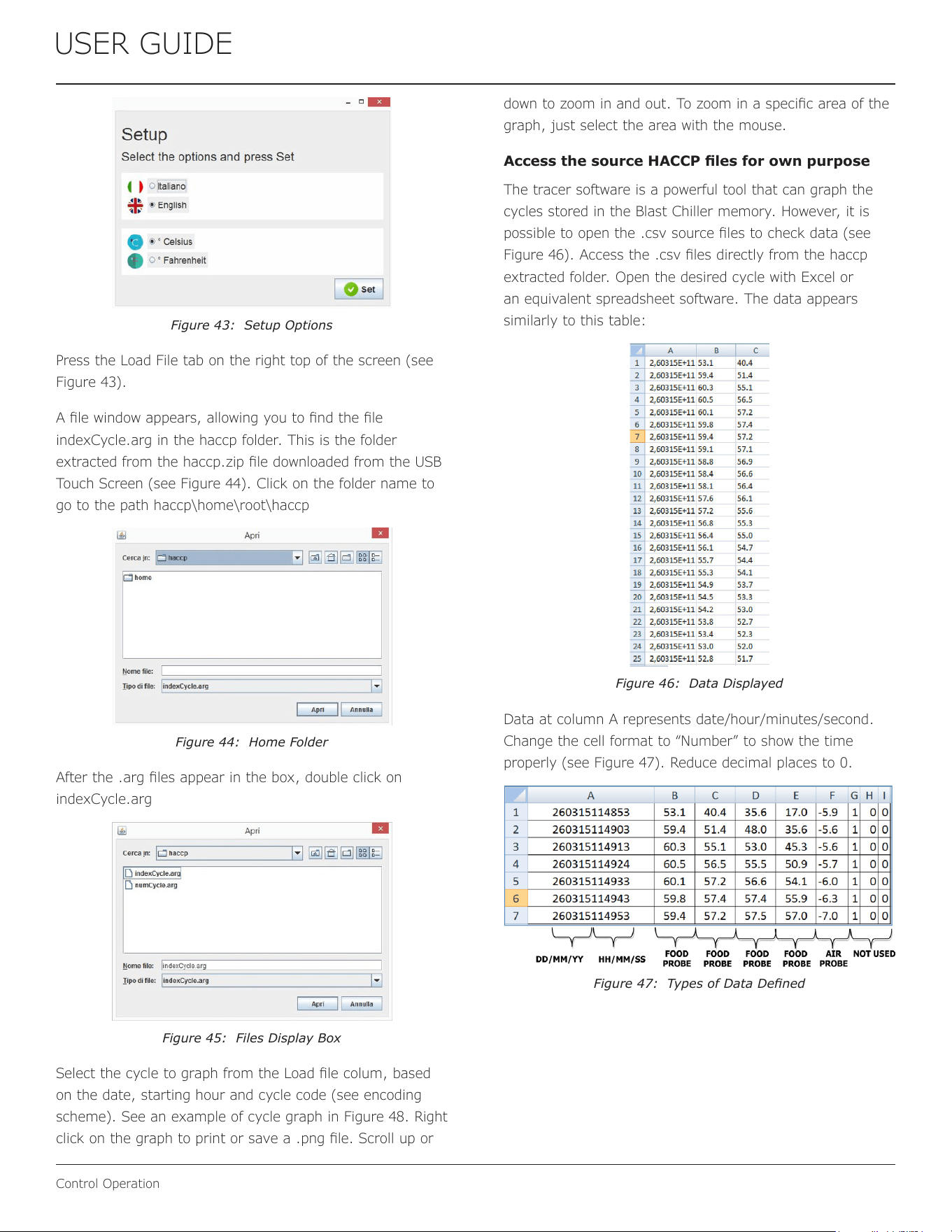
Figure 43: Setup Options
Press the Load File tab on the right top of the screen (see
Figure 43).
A le window appears, allowing you to nd the le
indexCycle.arg in the haccp folder. This is the folder
extracted from the haccp.zip le downloaded from the USB
Touch Screen (see Figure 44). Click on the folder name to
go to the path haccp\home\root\haccp
Figure 44: Home Folder
After the .arg les appear in the box, double click on
indexCycle.arg
Figure 45: Files Display Box
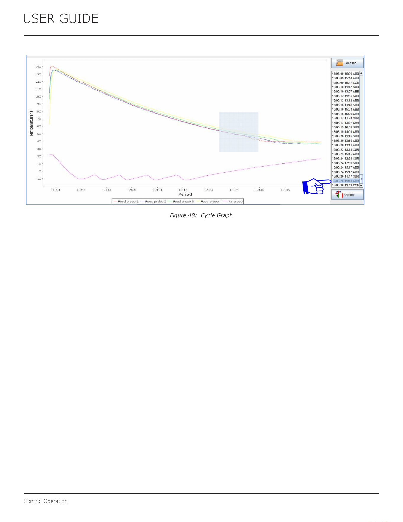
Select the cycle to graph from the Load le colum, based
on the date, starting hour and cycle code (see encoding
scheme). See an example of cycle graph in Figure 48. Right
click on the graph to print or save a .png le. Scroll up or
down to zoom in and out. To zoom in a specic area of the
graph, just select the area with the mouse.
Access the source HACCP les for own purpose
The tracer software is a powerful tool that can graph the
cycles stored in the Blast Chiller memory. However, it is
possible to open the .csv source les to check data (see
Figure 46). Access the .csv les directly from the haccp
extracted folder. Open the desired cycle with Excel or
an equivalent spreadsheet software. The data appears
similarly to this table:
Figure 46: Data Displayed
Data at column A represents date/hour/minutes/second.
Change the cell format to “Number” to show the time
properly (see Figure 47). Reduce decimal places to 0.
Figure 47: Types of Data Dened
22
USER GUIDE
Control Operation
Figure 48: Cycle Graph
23
USER GUIDE
Interior Adjustments
Interior Adjustments
BRACKETS
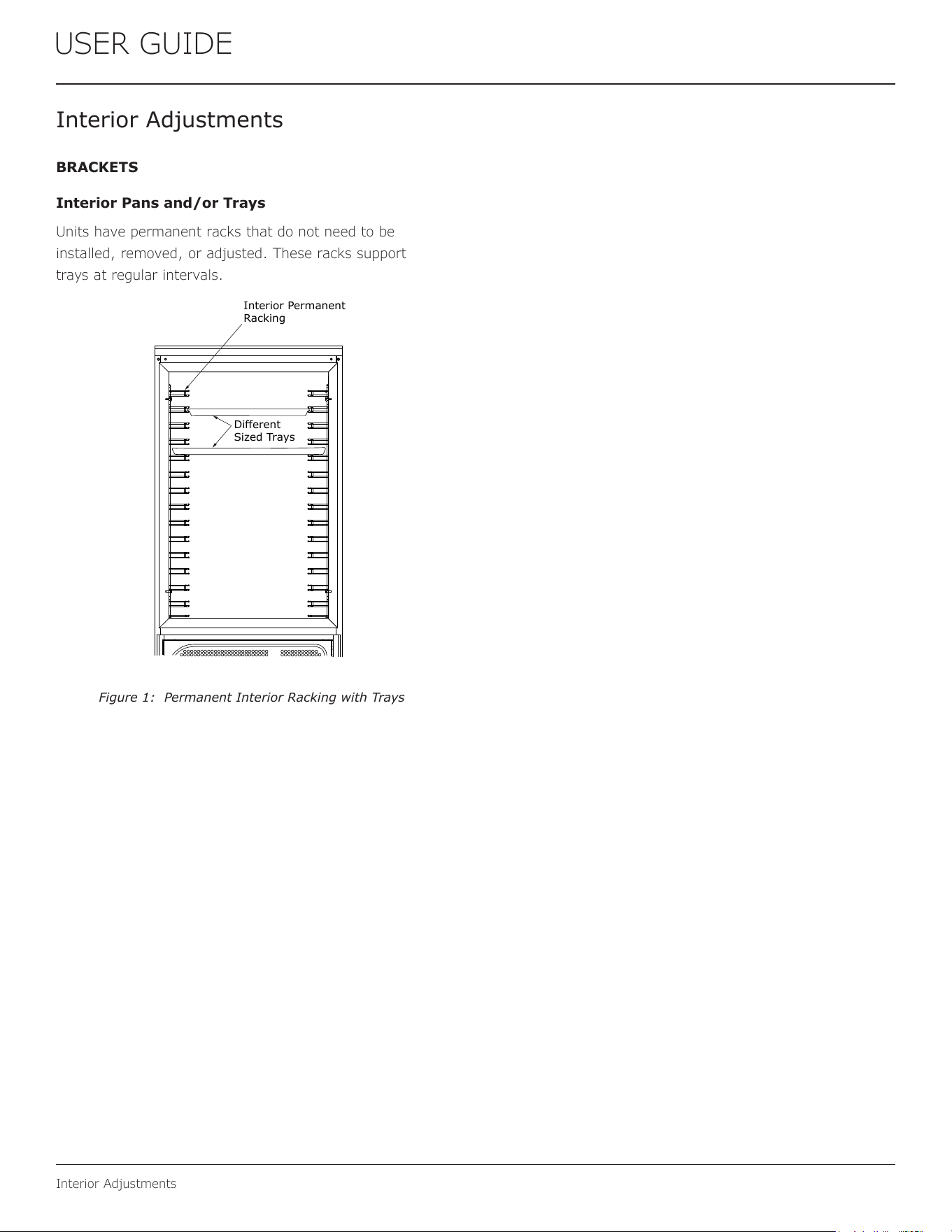
Interior Pans and/or Trays
Units have permanent racks that do not need to be
installed, removed, or adjusted. These racks support
trays at regular intervals.
Interior Permanent
Racking
Different
Sized Trays
Figure 1: Permanent Interior Racking with Trays
24
USER GUIDE
Cleaning
Cleaning
STAINLESS STEEL SURFACES
Do not expose stainless steel door panels, handles, and
frames to chlorine gas, pool chemicals, saltwater, or
cleaners with bleach. These agents can discolor stainless
steel surfaces.
Keep your stainless steel unit looking new by cleaning with
a good quality food-grade stainless steel cleaner and polish
monthly.
NOTE: Do not clean with steel wool pads.
NOTE: Donotusecleanersnotspecically
intended for stainless steel on stainless
steel surfaces (this includes glass, tile,
and counter cleaners).
NOTE: Do not use abrasive pads, such as
ScotchBrite™,theywillcausethegraining
in the stainless steel to become blurred.
NOTE: Rustnotcleaneduppromptlycan
penetrate the surface of the stainless steel
andcompleteremovaloftherustmaynot
be possible.
CLEAN INTERIOR COMPONENTS
Use warm or hot water with a food-grade cleaner to clean
all removed components and interior surfaces.
CLEAN EXTERIOR SURFACES
The following guidelines are recommended for cleaning
external parts and surfaces:
• Cleaning products: water and neutral non-abrasive
detergents (do NOT use solvents)
• Cleaning methods: waster with a cloth or a sponge
• Frequency: weekly
NOTICE
Donotuseanysolvent-basedorabrasive
cleaners.Thesetypesofcleanersmaytransfer
taste and/or odor to the interior products and
damage or discolor the interior.
DEFROSTING
This unit has both automatic and manual Defrost options.
Automatic Defrost
See the “Control Operation” section for information on the
Defrost option on the control panel.
Manual Defrost
WARNING
!
Do not use medical devices or other means to
accelerate the defrosting process other than
thoserecommendedbythemanufacturer.
CAUTION
!
DO NOT use an ice pick or other sharp instrument
to help speed up defrosting. These instruments
can puncture the inner lining or damage the
cooling unit.
CAUTION
!
DONOTuseanytypeofheatertodefrost.Usinga
heater to speed up defrosting can cause personal
injuryanddamagetotheinnerlining.
NOTICE
The drain pan was not designed to capture the
watercreatedwhenmanuallydefrosting.To
preventwaterfromoverowingthedrainpanand
possiblydamagingwatersensitiveooring,the
unitmustberemovedfromcabinetry.
To defrost the unit manually, perform the following steps:
1. Disconnect power to the unit.
2. Remove all products from the interior
3. Prop the door in an open position (2 in. [50 mm]
minimum).
4. Allow the frost to melt naturally.
5. After the frost melts completely, clean the interior
and all removed components. (See INTERIOR
COMPONENTS).
6. When the interior is dry, reconnect power and turn
unit on.
25
USER GUIDE
Cleaning Condenser
Cleaning Condenser
INTERVAL—WEEKLY
NOTICE
Failure to clean the condenser regularly can
cause the unit to malfunction. This could void the
warranty.
The eciency of the condenser unit is compromised by the
condenser being blocked. This conguration requires that
the condenser is cleaned weekly.
WARNING
!
Disconnect electric power to the unit before
cleaning the condenser.
Before cleaning the condenser, perform the following steps:
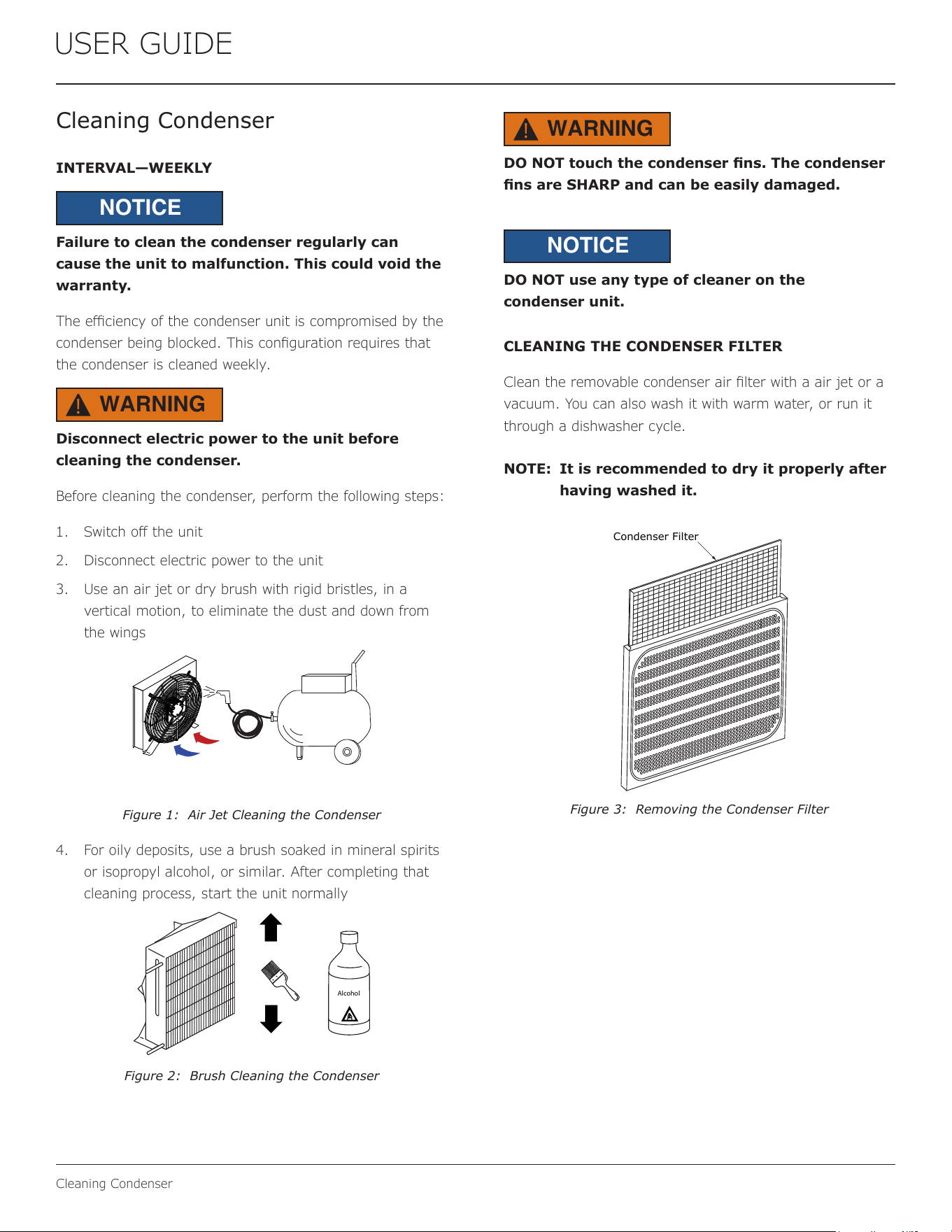
1. Switch o the unit
2. Disconnect electric power to the unit
3. Use an air jet or dry brush with rigid bristles, in a
vertical motion, to eliminate the dust and down from
the wings
Figure 1: Air Jet Cleaning the Condenser
4. For oily deposits, use a brush soaked in mineral spirits
or isopropyl alcohol, or similar. After completing that
cleaning process, start the unit normally
Alcohol
Figure 2: Brush Cleaning the Condenser
WARNING
!
DO NOT touch the condenser ns. The condenser
ns are SHARP and can be easily damaged.
NOTICE
DO NOT use any type of cleaner on the
condenser unit.
CLEANING THE CONDENSER FILTER
Clean the removable condenser air lter with a air jet or a
vacuum. You can also wash it with warm water, or run it
through a dishwasher cycle.
NOTE: It is recommended to dry it properly after
having washed it.
Condenser Filter
Figure 3: Removing the Condenser Filter
26
USER GUIDE
Extended Non-Use
Extended Non-Use
PROLONGED SHUTDOWN
The following steps are recommended for periods of
extended non-use:
1. Remove all consumable content from the unit.
2. Power the unit down while the Control Panel displays
“Standby”.
3. Disconnect the power cord from its outlet/socket
and leave it disconnected until the unit is returned to
service.
4. Clean and dry the interior of the unit. Ensure all water
has been removed from the unit.
5. Clean the system. (See the “Cleaning” section)
6. The door must remain open to prevent formation
of mold and mildew. Open door a minimum of 2”
(50 mm) to provide the necessary ventilation.
STORAGE
In the case of long periods of inactivity, the upright and/
or table refrigerators must be stored with attention to the
relevant storage place and time:
• Store the upright refrigerator in an enclosed area
• Protect upright refrigerator from bumps or stress
• Protect upright refrigerator from high thermal variation
• Prevent upright refrigerator from coming into contact
with corrosive substances
CAUTION
!
If the unit will be exposed to temperatures of
40°F (5°C) or less, the “Prolonged Shutdown”
and “Storage” steps must be followed.
CAUTION
!
Damage caused by freezing temperatures is not
covered by the warranty.
For questions regarding winterization, please call
U-Line at 414.354.0300.
27
USER GUIDE
Troubleshooting
Troubleshooting
WARNING
!
Before performing any service that involves
electrical disconnection and/or exposure
to electrical components, always follow the
Electrical LOCKOUT/TAGOUT Procedure.
Disconnect all circuits. Failure to comply can
cause property damage, injury, or death.
Perform thorough troubleshooing if the cause of a problem
is not obvious. To test the internal components, unplug or
remove the unit from the power supply.
PROBES
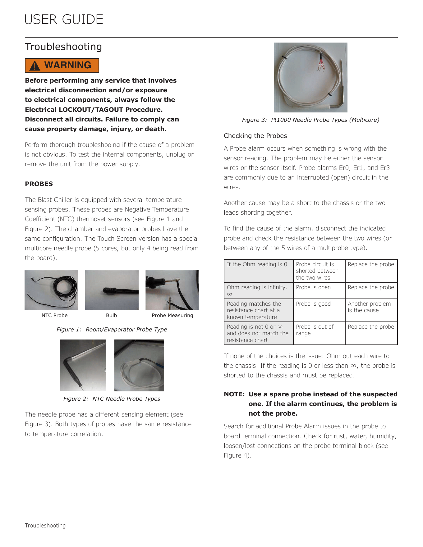
The Blast Chiller is equipped with several temperature
sensing probes. These probes are Negative Temperature
Coecient (NTC) thermoset sensors (see Figure 1 and
Figure 2). The chamber and evaporator probes have the
same conguration. The Touch Screen version has a special
multicore needle probe (5 cores, but only 4 being read from
the board).
NTC Probe Bulb Probe Measuring
Figure 1: Room/Evaporator Probe Type
Figure 2: NTC Needle Probe Types
The needle probe has a dierent sensing element (see
Figure 3). Both types of probes have the same resistance
to temperature correlation.
Figure 3: Pt1000 Needle Probe Types (Multicore)
Checking the Probes
A Probe alarm occurs when something is wrong with the
sensor reading. The problem may be either the sensor
wires or the sensor itself. Probe alarms Er0, Er1, and Er3
are commonly due to an interrupted (open) circuit in the
wires.
Another cause may be a short to the chassis or the two
leads shorting together.
To nd the cause of the alarm, disconnect the indicated
probe and check the resistance between the two wires (or
between any of the 5 wires of a multiprobe type).
If the Ohm reading is 0 Probe circuit is
shorted between
the two wires
Replace the probe
Ohm reading is innity,
∞
Probe is open Replace the probe
Reading matches the
resistance chart at a
known temperature
Probe is good Another problem
is the cause
Reading is not 0 or ∞
and does not match the
resistance chart
Probe is out of
range
Replace the probe
If none of the choices is the issue: Ohm out each wire to
the chassis. If the reading is 0 or less than ∞, the probe is
shorted to the chassis and must be replaced.
NOTE: Use a spare probe instead of the suspected
one. If the alarm continues, the problem is
not the probe.
Search for additional Probe Alarm issues in the probe to
board terminal connection. Check for rust, water, humidity,
loosen/lost connections on the probe terminal block (see
Figure 4).
28
USER GUIDE
Troubleshooting
Touch Screen Version
Probes Terminal Block
Standard Version
Figure 4: Probes Terminal Block Location
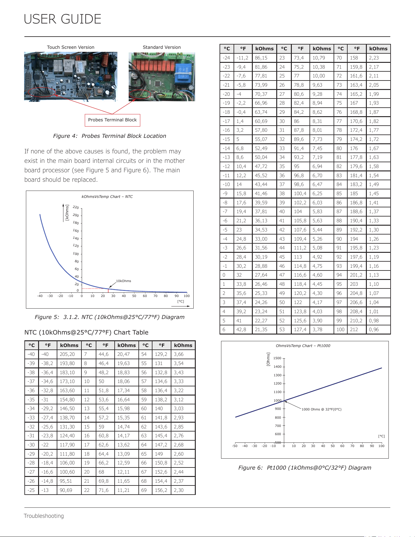
If none of the above causes is found, the problem may
exist in the main board internal circuits or in the mother
board processor (see Figure 5 and Figure 6). The main
board should be replaced.
kOhmsVsTemp Chart – NTC
[kOhms]
10kOhms
220
20
40
60
80
100
120
140
160
180
200
0
10-40 -30 -20 10090807060504030200-10
[°C]
Figure 5: 3.1.2. NTC (10kOhms@25°C/77°F) Diagram
NTC (10kOhms@25°C/77°F) Chart Table
°C °F kOhms °C °F kOhms °C °F kOhms
-40 -40 205,20 7 44,6 20,47 54 129,2 3,66
-39 -38,2 193,80 8 46,4 19,63 55 131 3,54
-38 -36,4 183,10 9 48,2 18,83 56 132,8 3,43
-37 -34,6 173,10 10 50 18,06 57 134,6 3,33
-36 -32,8 163,60 11 51,8 17,34 58 136,4 3,22
-35 -31 154,80 12 53,6 16,64 59 138,2 3,12
-34 -29,2 146,50 13 55,4 15,98 60 140 3,03
-33 -27,4 138,70 14 57,2 15,35 61 141,8 2,93
-32 -25,6 131,30 15 59 14,74 62 143,6 2,85
-31 -23,8 124,40 16 60,8 14,17 63 145,4 2,76
-30 -22 117,90 17 62,6 13,62 64 147,2 2,68
-29 -20,2 111,80 18 64,4 13,09 65 149 2,60
-28 -18,4 106,00 19 66,2 12,59 66 150,8 2,52
-27 -16,6 100,60 20 68 12,11 67 152,6 2,44
-26 -14,8 95,51 21 69,8 11,65 68 154,4 2,37
-25 -13 90,69 22 71,6 11,21 69 156,2 2,30
°C °F kOhms °C °F kOhms °C °F kOhms
-24 -11,2 86,15 23 73,4 10,79 70 158 2,23
-23 -9,4 81,86 24 75,2 10,38 71 159,8 2,17
-22 -7,6 77,81 25 77 10,00 72 161,6 2,11
-21 -5,8 73,99 26 78,8 9,63 73 163,4 2,05
-20 -4 70,37 27 80,6 9,28 74 165,2 1,99
-19 -2,2 66,96 28 82,4 8,94 75 167 1,93
-18 -0,4 63,74 29 84,2 8,62 76 168,8 1,87
-17 1,4 60,69 30 86 8,31 77 170,6 1,82
-16 3,2 57,80 31 87,8 8,01 78 172,4 1,77
-15 5 55,07 32 89,6 7,73 79 174,2 1,72
-14 6,8 52,49 33 91,4 7,45 80 176 1,67
-13 8,6 50,04 34 93,2 7,19 81 177,8 1,63
-12 10,4 47,72 35 95 6,94 82 179,6 1,58
-11 12,2 45,52 36 96,8 6,70 83 181,4 1,54
-10 14 43,44 37 98,6 6,47 84 183,2 1,49
-9 15,8 41,46 38 100,4 6,25 85 185 1,45
-8 17,6 39,59 39 102,2 6,03 86 186,8 1,41
-7 19,4 37,81 40 104 5,83 87 188,6 1,37
-6 21,2 36,13 41 105,8 5,63 88 190,4 1,33
-5 23 34,53 42 107,6 5,44 89 192,2 1,30
-4 24,8 33,00 43 109,4 5,26 90 194 1,26
-3 26,6 31,56 44 111,2 5,08 91 195,8 1,23
-2 28,4 30,19 45 113 4,92 92 197,6 1,19
-1 30,2 28,88 46 114,8 4,75 93 199,4 1,16
0 32 27,64 47 116,6 4,60 94 201,2 1,13
1 33,8 26,46 48 118,4 4,45 95 203 1,10
2 35,6 25,33 49 120,2 4,30 96 204,8 1,07
3 37,4 24,26 50 122 4,17 97 206,6 1,04
4 39,2 23,24 51 123,8 4,03 98 208,4 1,01
5 41 22,27 52 125,6 3,90 99 210,2 0,98
6 42,8 21,35 53 127,4 3,78 100 212 0,96
OhmsVsTemp Chart – Pt1000
[Ohms]
1000 Ohms @ 32°F(0°C)
1500
500
600
700
800
900
1000
1100
1200
1300
1400
10-40 -30 -20 10090807060504030200-10
[°C]
-50
Figure 6: Pt1000 (1kOhms@0°C/32°F) Diagram
29
USER GUIDE
Troubleshooting
°C °F Ohms °C °F Ohms
-50 -58 803,10 35 95 1136,10
-45 -49 822,90 40 104 1155,40
-40 -40 842,70 45 113 1174,70
-35 -31 862,50 50 122 1194,00
-30 -22 882,20 55 131 1214,90
-25 -13 901,90 60 140 1232,40
-20 -4 921,60 65 149 1251,60
-15 5 941,20 70 158 1270,70
-10 14 960,90 75 167 1289,80
-5 23 980,40 80 176 1308,90
0 32 1000,00 85 185 1328,00
5 41 1019,50 90 194 1347,00
10 50 1039,00 95 203 1366,00
15 59 1058,50 100 212 1385,00
20 68 1077,90 105 221 1403,90
25 77 1097,30 110 230 1422,90
30 86 1116,70 150 302 1573,10
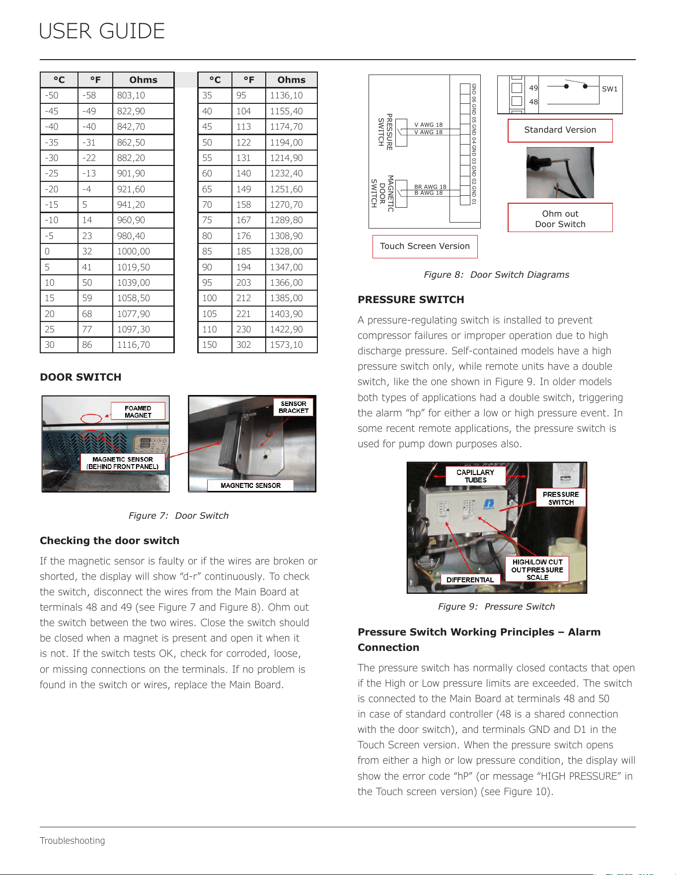
DOOR SWITCH
The Blast Chiller is equipped with a magnetic sensor. When
the door is closed the sensor is activated by a magnet built
into the door. There are two magnets in each door, one at
the top and one at the bottom. This allows the door to be
reversed (only for non Touch Screen version).
Figure 7: Door Switch
Checking the door switch
If the magnetic sensor is faulty or if the wires are broken or
shorted, the display will show “d-r” continuously. To check
the switch, disconnect the wires from the Main Board at
terminals 48 and 49 (see Figure 7 and Figure 8). Ohm out
the switch between the two wires. Close the switch should
be closed when a magnet is present and open it when it
is not. If the switch tests OK, check for corroded, loose,
or missing connections on the terminals. If no problem is
found in the switch or wires, replace the Main Board.
49
48
SW1
V AWG 18
V AWG 18
BR AWG 18
B AWG 18
GND 04GND 06 GND 03 GND 01GND 02GND 05
PRESSURE
SWITCH
MAGNETIC
DOOR
SWITCH
Touch Screen Version
Standard Version
Ohm out
Door Switch
Figure 8: Door Switch Diagrams
PRESSURE SWITCH
A pressure-regulating switch is installed to prevent
compressor failures or improper operation due to high
discharge pressure. Self-contained models have a high
pressure switch only, while remote units have a double
switch, like the one shown in Figure 9. In older models
both types of applications had a double switch, triggering
the alarm “hp” for either a low or high pressure event. In
some recent remote applications, the pressure switch is
used for pump down purposes also.
Figure 9: Pressure Switch
Pressure Switch Working Principles – Alarm
Connection
The pressure switch has normally closed contacts that open
if the High or Low pressure limits are exceeded. The switch
is connected to the Main Board at terminals 48 and 50
in case of standard controller (48 is a shared connection
with the door switch), and terminals GND and D1 in the
Touch Screen version. When the pressure switch opens
from either a high or low pressure condition, the display will
show the error code “hP” (or message “HIGH PRESSURE” in
the Touch screen version) (see Figure 10).
30

USER GUIDE
Troubleshooting
Figure 10: Alarm Connection to the Pressure Switch
V AWG 18
V AWG 18
BR AWG 18
B AWG 18
GND 04GND 06 GND 03 GND 01GND 02GND 05
PRESSURE
SWITCH
MAGNETIC
DOOR
SWITCH
Touch Screen
Version
Figure 11: Pressure Switch
Current models only have a high pressure switch. After the
pressures return to the normal range, the pressure switch
resets automatically. Current remote applications do not
have an alarm connection with the pressure switch, but
will be used to pump down by low pressure, or to cut out
compressor in case of high pressure (see Figure 10 and
Figure 11).
Pressure Switch Working Principles – Pump Down
Remote applications have a double pressure switch. A
solenoid valve feeds refrigerant to the evaporator. This
valve is closed when setpoint temperature is reached in
the cabinet, allowing the compressor to pump down until
pressure switch trips due to low suction pressure. The
pressure switch will cut out the compressor contactor’s coil
in this case, either for low pressure (pump down) or high
pressure (safety).
NOTE: No high pressure alarm message will
be displayed from the controller if the
remote chillers are working in pump down
conguration.
Pressure Switch Factory Setting
The pressure switch factory settings appear in the following
list:
NOTE: Do not change these settings!
• High pressure limit = 29 barg (425 psig)
• Low pressure limit = 0 barg (0 psig)
• Dierential = 1,2 barg (18 psig)
DOOR FRAME HEATER
Both Shock Freezer and Blast Chiller units come equipped
with a door frame heater to prevent frost build-up on
the door gasket. The heater may be either 115V or 220V
depending on the model/rating. For 220V 3-phase units (or
220V single-phase units with no neutral), the door frame
heater is connected between two live mains. The heater
runs around the frame, under a plastic strip cover (see
Figure 12). Electrical connections run through the lower
cabinet panel to the electrical component box.
Figure 12: Door Frame Heater Components
Heater cable features
Heater Cable Specications
115V 220V
Length 2.4 m 2 m (Heated)
Resistance 1.4 kΩ 2.4 kΩ
Current 80 mAmps 90 mAmps
MAIN BOARD – STANDARD CONTROLLER
Each unit is equipped with a Main Board where the
electrical components are connected. The board has
10 outputs (10 relays) as shown below. The relays control
various components.
RELAY RELATED COMPONENT
K1 (Load1) COMPRESSOR CONTACTOR
COIL
K2 (Load2) PUMP-DOWN VALVE
K3 (Load3) EVAPORATOR FAN MOTOR
CONTACTOR COIL
K4 (Load4) DEFROST VALVE
K5 (Load5) UV LAMP
K6 (Load6) HEATED NEEDLE PROBE
K7 (Load7) CONDENSER FAN MOTOR
CONTACTOR COIL
K8 (Load8) DOOR FRAME HEATER
K9 (Load9) LIGHT
K10 (Load10) ALARM
31
USER GUIDE
Troubleshooting
Depending on the unit’s voltage rating, each load is directly
connected to either L1 or Neutral. L2 is switched by the
dedicated relay.
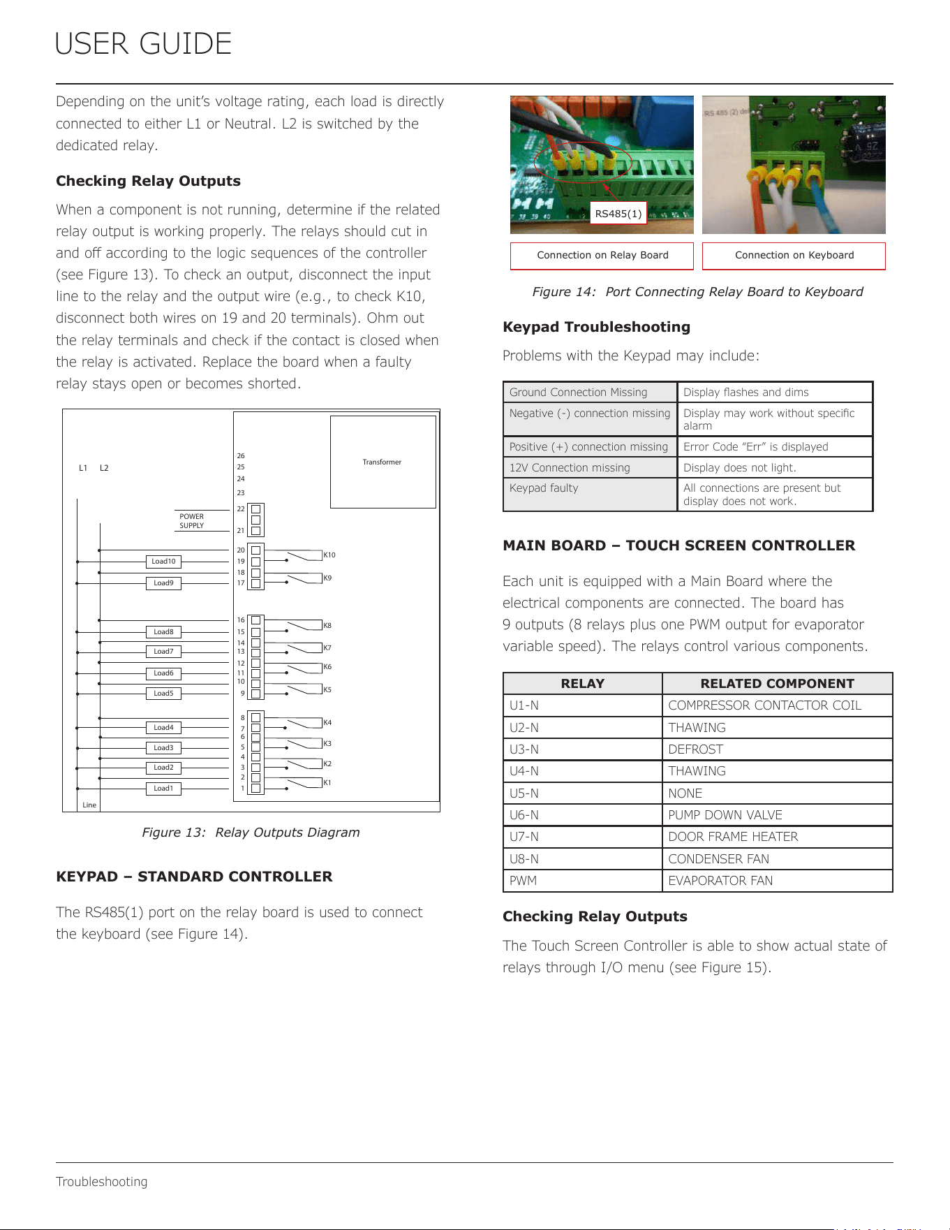
Checking Relay Outputs
When a component is not running, determine if the related
relay output is working properly. The relays should cut in
and o according to the logic sequences of the controller
(see Figure 13). To check an output, disconnect the input
line to the relay and the output wire (e.g., to check K10,
disconnect both wires on 19 and 20 terminals). Ohm out
the relay terminals and check if the contact is closed when
the relay is activated. Replace the board when a faulty
relay stays open or becomes shorted.
Transformer
L1 L2
POWER
SUPPLY
Load10
K8
K7
Load2
Load4
Load6
Load9
K9
K10
Load1
Load3
Load5
Load8
Load7
K6
K1
K2
K3
K4
K5
Line
1
21
20
19
18
17
16
15
14
13
12
11
10
9
8
7
6
5
4
3
2
26
25
24
23
22
Figure 13: Relay Outputs Diagram
KEYPAD – STANDARD CONTROLLER
The RS485(1) port on the relay board is used to connect
the keyboard (see Figure 14).
Connection on Relay Board Connection on Keyboard
RS485(1)
Figure 14: Port Connecting Relay Board to Keyboard
Keypad Troubleshooting
Problems with the Keypad may include:
Ground Connection Missing Display ashes and dims
Negative (-) connection missing Display may work without specic
alarm
Positive (+) connection missing Error Code “Err” is displayed
12V Connection missing Display does not light.
Keypad faulty All connections are present but
display does not work.
MAIN BOARD – TOUCH SCREEN CONTROLLER
Each unit is equipped with a Main Board where the
electrical components are connected. The board has
9 outputs (8 relays plus one PWM output for evaporator
variable speed). The relays control various components.
RELAY RELATED COMPONENT
U1-N COMPRESSOR CONTACTOR COIL
U2-N THAWING
U3-N DEFROST
U4-N THAWING
U5-N NONE
U6-N PUMP DOWN VALVE
U7-N DOOR FRAME HEATER
U8-N CONDENSER FAN
PWM EVAPORATOR FAN
Checking Relay Outputs
The Touch Screen Controller is able to show actual state of
relays through I/O menu (see Figure 15).
32
USER GUIDE
Troubleshooting
FOOD PROBE 1
I FOOD PROBE 2
FOOD PROBE3
EVAPORATOR PROBE
OVERHTING PROBE
PRESSURE PROBE
l
ovERHEATING
Ext
-
27/03/2015
Int - 13:53:45
0 °F
-2 °F
-4 "F
-6 "F
25 "F
-31 °F
--.-
-·-.-
---■-
0 °F
(/0
t.
DESMON
.
DOOR SWlTCH 1
DOOR SWCH 2
MAGNETOTHMIC
HlGH PRSURE SWCH
LOW PRESSURE SWITCH
KRIWAN
OUTPUT
FAN
DE T CONDENSER
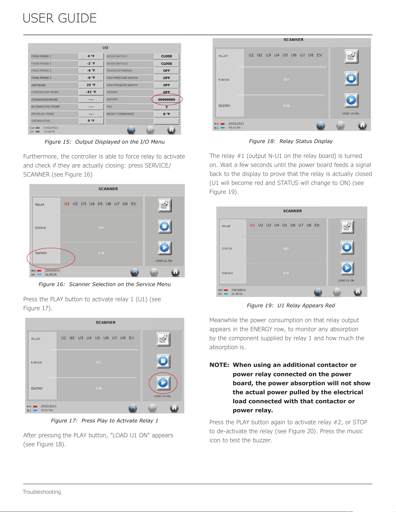
Figure 15: Output Displayed on the I/O Menu
Furthermore, the controller is able to force relay to activate
and check if they are actually closing: press SERVICE/
SCANNER (see Figure 16)
Figure 16: Scanner Selection on the Service Menu
Press the PLAY button to activate relay 1 (U1) (see
Figure 17).
Figure 17: Press Play to Activate Relay 1
After pressing the PLAY button, “LOAD U1 ON” appears
(see Figure 18).
Figure 18: Relay Status Display
The relay #1 (output N-U1 on the relay board) is turned
on. Wait a few seconds until the power board feeds a signal
back to the display to prove that the relay is actually closed
(U1 will become red and STATUS will change to ON) (see
Figure 19).
REY
SUS
ENERGY
Ext - 2s103no1s
Int - 11:36:55
SCANNER
" DESMON
.
Ul U2 U3 U4 US U6 U7 U8 EV.
•
LOAD Ul ON
Figure 19: U1 Relay Appears Red
Meanwhile the power consumption on that relay output
appears in the ENERGY row, to monitor any absorption
by the component supplied by relay 1 and how much the
absorption is.
NOTE: When using an additional contactor or
power relay connected on the power
board, the power absorption will not show
the actual power pulled by the electrical
load connected with that contactor or
power relay.
Press the PLAY button again to activate relay #2, or STOP
to de-activate the relay (see Figure 20). Press the music
icon to test the buzzer.
33
USER GUIDE
Troubleshooting
REY
SUS
ENERGY
Ext - 25/03/2015
Int - 12:00:57
SCANNER
. DESMON
.
Ul U2 U3 U4 us U6 U7 ua EV.
•
LOAD U2 ON
Figure 20: Activating Relay #2
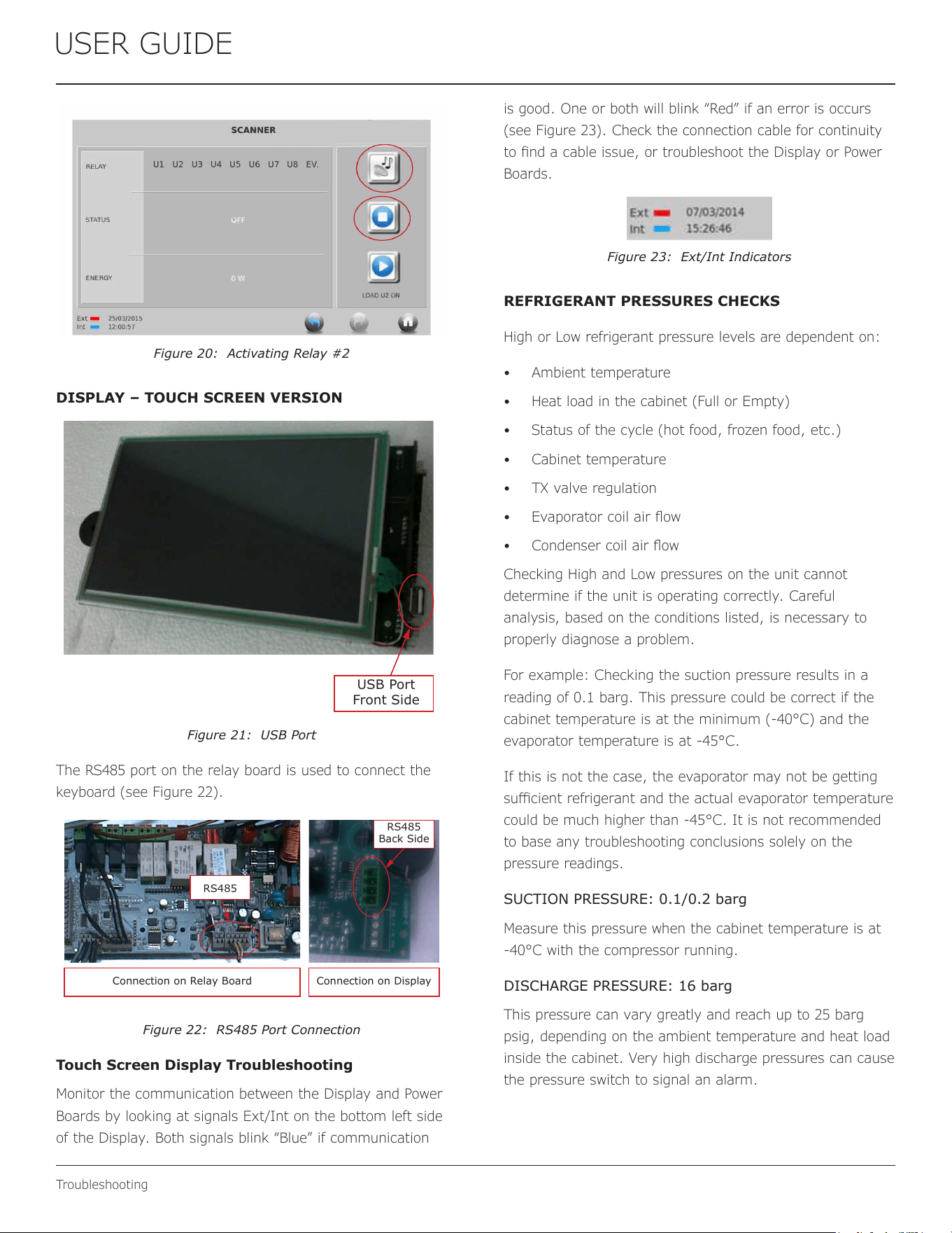
DISPLAY – TOUCH SCREEN VERSION
USB Port
Front Side
Figure 21: USB Port
The RS485 port on the relay board is used to connect the
keyboard (see Figure 22).
Connection on Relay Board
RS485
Connection on Display
RS485
Back Side
Figure 22: RS485 Port Connection
Touch Screen Display Troubleshooting
Monitor the communication between the Display and Power
Boards by looking at signals Ext/Int on the bottom left side
of the Display. Both signals blink “Blue” if communication
is good. One or both will blink “Red” if an error is occurs
(see Figure 23). Check the connection cable for continuity
to nd a cable issue, or troubleshoot the Display or Power
Boards.
Figure 23: Ext/Int Indicators
REFRIGERANT PRESSURES CHECKS
High or Low refrigerant pressure levels are dependent on:
• Ambient temperature
• Heat load in the cabinet (Full or Empty)
• Status of the cycle (hot food, frozen food, etc.)
• Cabinet temperature
• TX valve regulation
• Evaporator coil air ow
• Condenser coil air ow
Checking High and Low pressures on the unit cannot
determine if the unit is operating correctly. Careful
analysis, based on the conditions listed, is necessary to
properly diagnose a problem.
For example: Checking the suction pressure results in a
reading of 0.1 barg. This pressure could be correct if the
cabinet temperature is at the minimum (-40°C) and the
evaporator temperature is at -45°C.
If this is not the case, the evaporator may not be getting
sucient refrigerant and the actual evaporator temperature
could be much higher than -45°C. It is not recommended
to base any troubleshooting conclusions solely on the
pressure readings.
SUCTION PRESSURE: 0.1/0.2 barg
Measure this pressure when the cabinet temperature is at
-40°C with the compressor running.
DISCHARGE PRESSURE: 16 barg
This pressure can vary greatly and reach up to 25 barg
psig, depending on the ambient temperature and heat load
inside the cabinet. Very high discharge pressures can cause
the pressure switch to signal an alarm.
34
USER GUIDE
Wire Diagram 1
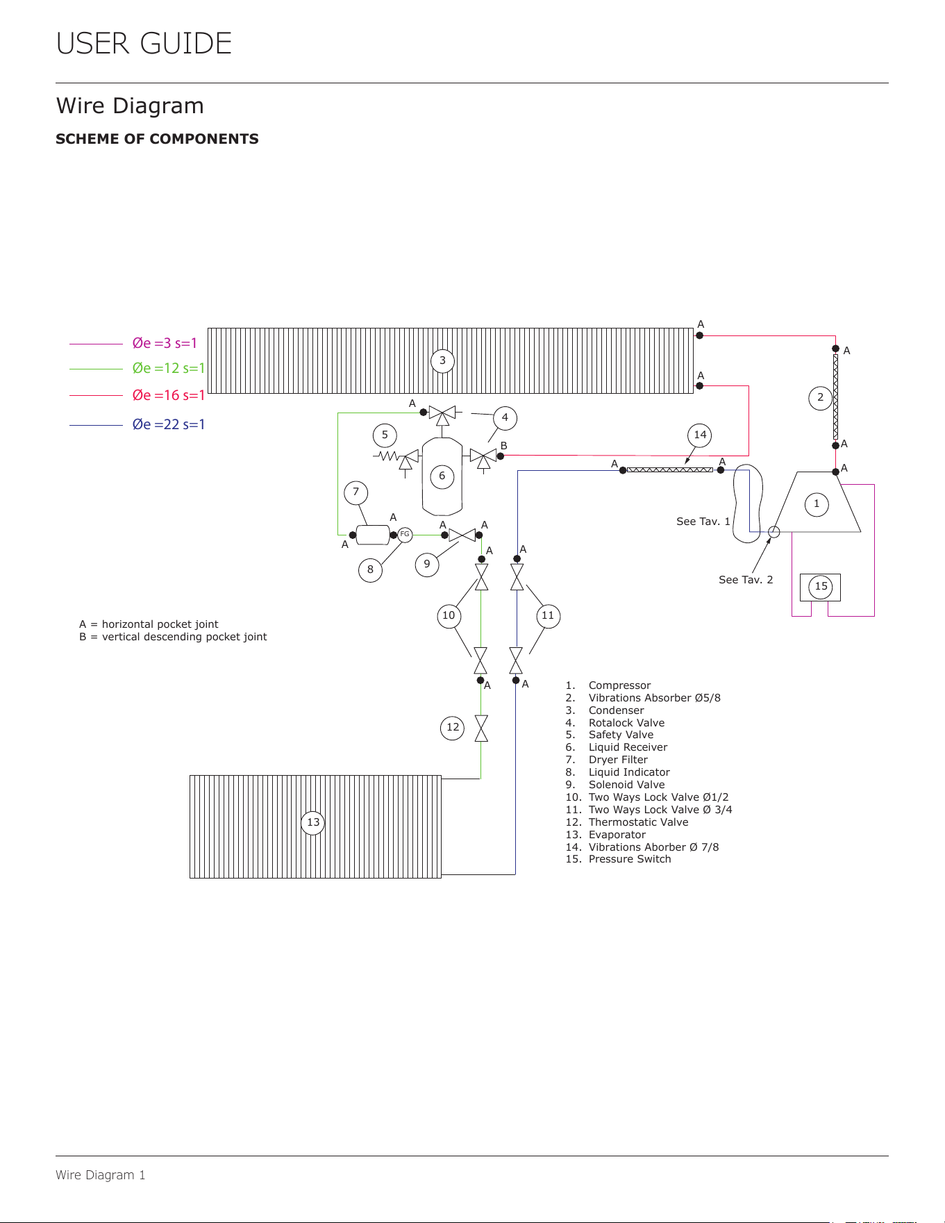
Wire Diagram
SCHEME OF COMPONENTS
Øe =3 s=1
Øe =22 s=1
Øe =16 s=1
Øe =12 s=1
3
13
15
1
2
14
12
1110
9
8
6
5
7
A
A
A
A A
A
A
A
A
A
A
A
A
A
A
A
B
A = horizontal pocket joint
B = vertical descending pocket joint
1. Compressor
2. Vibrations Absorber Ø5/8
3. Condenser
4. Rotalock Valve
5. Safety Valve
6. Liquid Receiver
7. Dryer Filter
8. Liquid Indicator
9. Solenoid Valve
10. Two Ways Lock Valve Ø1/2
11. Two Ways Lock Valve Ø 3/4
12. Thermostatic Valve
13. Evaporator
14. Vibrations Aborber Ø 7/8
15. Pressure Switch
FG
See Tav. 1
See Tav. 2
4
35
USER GUIDE
Wire Diagram 1
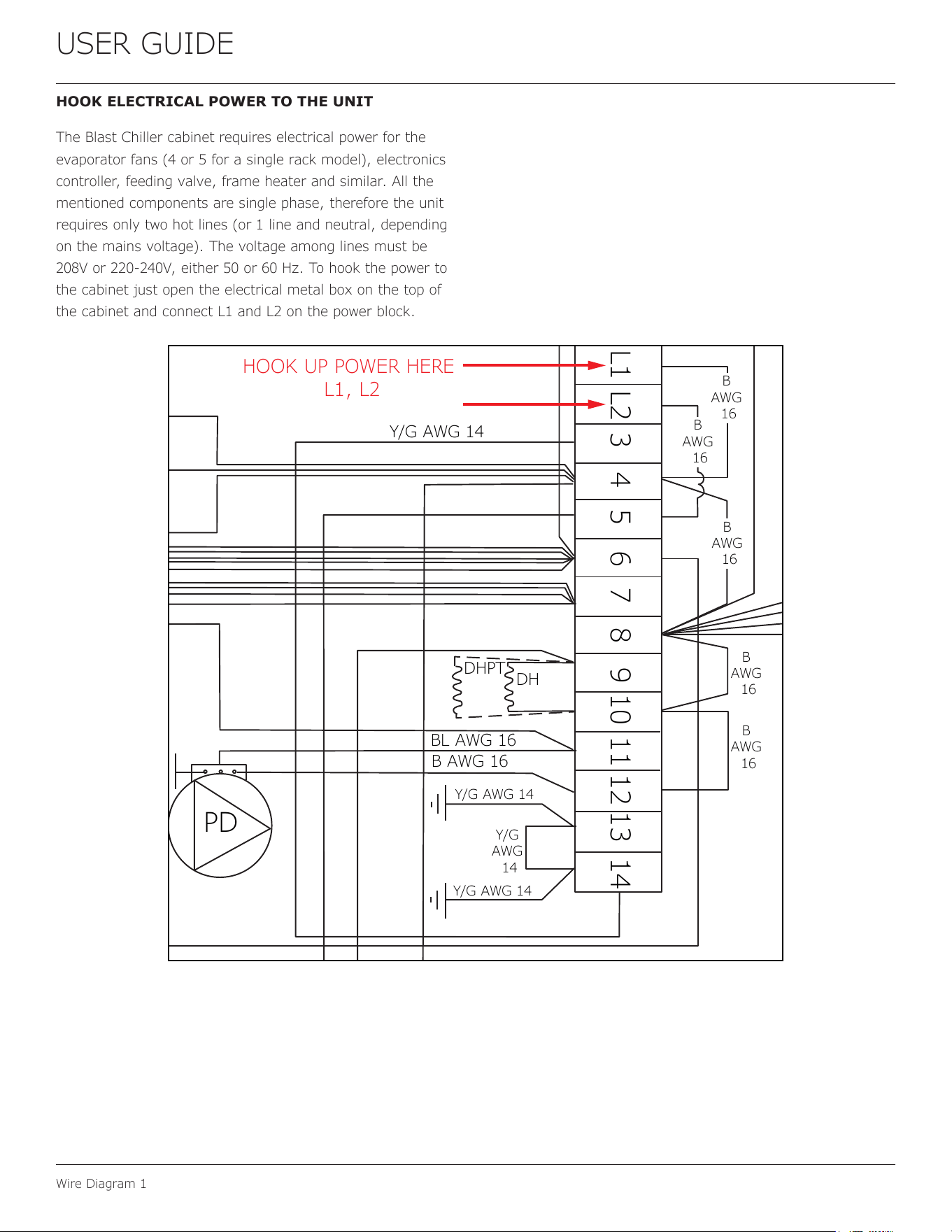
HOOK ELECTRICAL POWER TO THE UNIT
The Blast Chiller cabinet requires electrical power for the
evaporator fans (4 or 5 for a single rack model), electronics
controller, feeding valve, frame heater and similar. All the
mentioned components are single phase, therefore the unit
requires only two hot lines (or 1 line and neutral, depending
on the mains voltage). The voltage among lines must be
208V or 220-240V, either 50 or 60 Hz. To hook the power to
the cabinet just open the electrical metal box on the top of
the cabinet and connect L1 and L2 on the power block.
HOOK UP POWER HERE
L1, L2
BL
AWG
16
Y/G AWG 14
B
AWG
16
B
AWG
16
B
AWG
16
B
AWG
16
B
AWG
16
DHPT
DH
BL AWG 16
B AWG 16
Y/G AWG 14
Y/G
AWG
14
Y/G AWG 14
PD
L1 L2 3 4 5 6 7 8 9 10 11 12 13 14
36
USER GUIDE
Wire Diagram 1
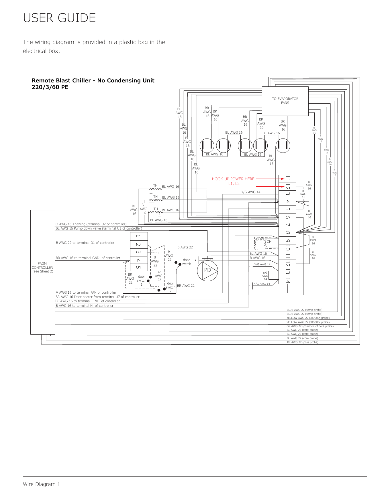
The wiring diagram is provided in a plastic bag in the
electrical box.
O AWG 16 Thawing (terminal U2 of controller)
FROM
CONTROLLER
(see Sheet 2)
HOOK UP POWER HERE
L1, L2
BL AWG 16 Pump down valve (terminal U1 of controller)
B AWG 22 to terminal D1 of controller
BR AWG 16 to terminal GND of controller
V AWG 16 to terminal FAN of controller
BR AWG 16 Door heater from terminal U7 of controller
BL AWG 16 to terminal LINE of controller
B AWG 16 to terminal N of controller
door
switch
B AWG 22
BR AWG 22
door
switch
2
door
switch
1
B
AWG
22
B
AWG
22
BR
AWG
22
BR
AWG
22
BL AWG 16
BL AWG 16
BL AWG 16
BL
AWG
16
BL
AWG
16
BL AWG 16
BL
AWG
16
BL
AWG
16
BL
AWG
16
BL
AWG
16
BL
AWG
16
BR
AWG
16
BR
AWG
16
BR
AWG
16
BR
AWG
16
BR
AWG
16
BL AWG 16
BL AWG 16
BL AWG 16
BL AWG 16
Y/G AWG 14
B
AWG
16
B
AWG
16
B
AWG
16
B
AWG
16
B
AWG
16
BLUE AWG 22 (temp probe)
BLUE AWG 22 (temp probe)
YELLOW AWG 22 (XXXXXX probe)
YELLOW AWG 22 (XXXXXX probe)
GR AWG 22 (common of core probe)
BL AWG 22 (core probe)
BL AWG 22 (core probe)
BL AWG 22 (core probe)
BL AWG 22 (core probe)
TO EVAPORATOR
FANS
TH
TH
TH
B
AWG
16
B
AWG
16
B
AWG
16
B
AWG
16
B
AWG
16
BL
AWG
16
DHPT
DH
BL AWG 16
B AWG 16
Y/G AWG 14
Y/G
AWG
14
Y/G AWG 14
PD
1 2 3 4 5
L1 L2 3 4 5 6 7 8 9 10 11 12 13 14
Remote Blast Chiller - No Condensing Unit
220/3/60 PE
37
USER GUIDE
Product Liability
Product Liability
Field service technicians are authorized to make an initial
assessment in the event of reported damages. If there are
any questions about the process involved, the technician
should call U-Line for further explanation.
While inspecting for defects or installation issues, photos
should be taken to document any damages or issues found.
During the assessment, if the service technician is able to
nd the source of the damage and it can be resolved by
replacement of a part, the servicer is authorized to replace
the part in question. The part that caused the damage
must be returned to U-Line in its entirety. The part must
be clearly labeled with the serial number of the unit it was
removed from, the date, and the servicer who removed the
part.
If the service technician determines the damage is the
result of installation issues (water connection/drain, etc.),
the consumer would be notied and the issues shall be
resolved at the direction of the consumer.
If damage is evident and the service technician is
unable to nd the source, U-Line must be contacted at
+1.414.354.0300 for further direction.
8900 N. 55th Street • Milwaukee, WI 53223
T: +1.414.354.0300 • F: +1.414.354.5696
Website: www.u-line.com
Right product. Right place.
Right temperature Since 1962.
38
u-line.com • +1.414.354.0300 • sales@u-line.com
Please visit u-line.com to view User Guides & Service Manuals. All specications are subject to change without notice.
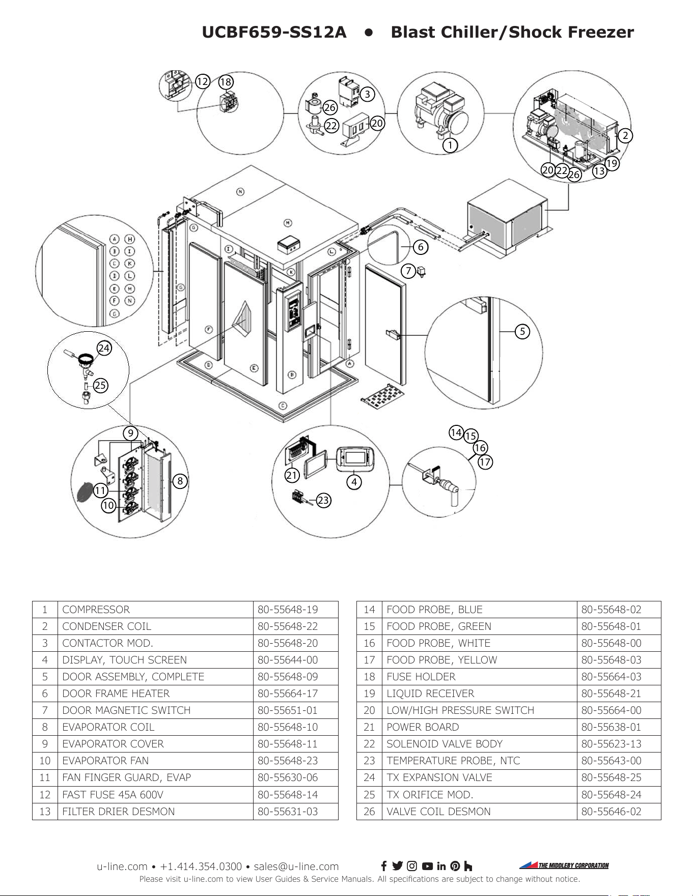
UCBF659-SS12A • Blast Chiller/Shock Freezer
1
2
3
4
5
8
9
6
7
10
11
12
13
19
20
20
21
23
16
17
26
26
15
14
24
25
22
22
18
14 FOOD PROBE, BLUE 80-55648-02
15 FOOD PROBE, GREEN 80-55648-01
16 FOOD PROBE, WHITE 80-55648-00
17 FOOD PROBE, YELLOW 80-55648-03
18 FUSE HOLDER 80-55664-03
19 LIQUID RECEIVER 80-55648-21
20 LOW/HIGH PRESSURE SWITCH 80-55664-00
21 POWER BOARD 80-55638-01
22 SOLENOID VALVE BODY 80-55623-13
23 TEMPERATURE PROBE, NTC 80-55643-00
24 TX EXPANSION VALVE 80-55648-25
25 TX ORIFICE MOD. 80-55648-24
26 VALVE COIL DESMON 80-55646-02
1 COMPRESSOR 80-55648-19
2 CONDENSER COIL 80-55648-22
3 CONTACTOR MOD. 80-55648-20
4 DISPLAY, TOUCH SCREEN 80-55644-00
5 DOOR ASSEMBLY, COMPLETE 80-55648-09
6 DOOR FRAME HEATER 80-55664-17
7 DOOR MAGNETIC SWITCH 80-55651-01
8 EVAPORATOR COIL 80-55648-10
9 EVAPORATOR COVER 80-55648-11
10 EVAPORATOR FAN 80-55648-23
11 FAN FINGER GUARD, EVAP 80-55630-06
12 FAST FUSE 45A 600V 80-55648-14
13 FILTER DRIER DESMON 80-55631-03
39
USER GUIDE
System Diagnosis Guide
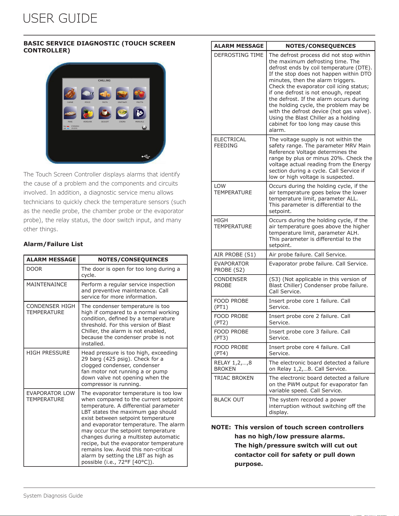
BASIC SERVICE DIAGNOSTIC (TOUCH SCREEN
CONTROLLER)
The Touch Screen Controller displays alarms that identify
the cause of a problem and the components and circuits
involved. In addition, a diagnostic service menu allows
technicians to quickly check the temperature sensors (such
as the needle probe, the chamber probe or the evaporator
probe), the relay status, the door switch input, and many
other things.
Alarm/Failure List
ALARM MESSAGE NOTES/CONSEQUENCES
DOOR The door is open for too long during a
cycle.
MAINTENAINCE Perform a regular service inspection
and preventive maintenance. Call
service for more information.
CONDENSER HIGH
TEMPERATURE
The condenser temperature is too
high if compared to a normal working
condition, dened by a temperature
threshold. For this version of Blast
Chiller, the alarm is not enabled,
because the condenser probe is not
installed.
HIGH PRESSURE Head pressure is too high, exceeding
29 barg (425 psig). Check for a
clogged condenser, condenser
fan motor not running a or pump
down valve not opening when the
compressor is running.
EVAPORATOR LOW
TEMPERATURE
The evaporator temperature is too low
when compared to the current setpoint
temperature. A dierential parameter
LBT states the maximum gap should
exist between setpoint temperature
and evaporator temperature. The alarm
may occur the setpoint temperature
changes during a multistep automatic
recipe, but the evaporator temperature
remains low. Avoid this non-critical
alarm by setting the LBT as high as
possible (i.e., 72°F [40°C]).
ALARM MESSAGE NOTES/CONSEQUENCES
DEFROSTING TIME The defrost process did not stop within
the maximum defrosting time. The
defrost ends by coil temperature (DTE).
If the stop does not happen within DTO
minutes, then the alarm triggers.
Check the evaporator coil icing status;
if one defrost is not enough, repeat
the defrost. If the alarm occurs during
the holding cycle, the problem may be
with the defrost device (hot gas valve).
Using the Blast Chiller as a holding
cabinet for too long may cause this
alarm.
ELECTRICAL
FEEDING
The voltage supply is not within the
safety range. The parameter MRV Main
Reference Voltage determines the
range by plus or minus 20%. Check the
voltage actual reading from the Energy
section during a cycle. Call Service if
low or high voltage is suspected.
LOW
TEMPERATURE
Occurs during the holding cycle, if the
air temperature goes below the lower
temperature limit, parameter ALL.
This parameter is dierential to the
setpoint.
HIGH
TEMPERATURE
Occurs during the holding cycle, if the
air temperature goes above the higher
temperature limit, parameter ALH.
This parameter is dierential to the
setpoint.
AIR PROBE (S1) Air probe failure. Call Service.
EVAPORATOR
PROBE (S2)
Evaporator probe failure. Call Service.
CONDENSER
PROBE
(S3) (Not applicable in this version of
Blast Chiller) Condenser probe failure.
Call Service.
FOOD PROBE
(PT1)
Insert probe core 1 failure. Call
Service.
FOOD PROBE
(PT2)
Insert probe core 2 failure. Call
Service.
FOOD PROBE
(PT3)
Insert probe core 3 failure. Call
Service.
FOOD PROBE
(PT4)
Insert probe core 4 failure. Call
Service.
RELAY 1,2,…,8
BROKEN
The electronic board detected a failure
on Relay 1,2,…8. Call Service.
TRIAC BROKEN The electronic board detected a failure
on the PWM output for evaporator fan
variable speed. Call Service.
BLACK OUT The system recorded a power
interruption without switching o the
display.
NOTE: This version of touch screen controllers
has no high/low pressure alarms.
The high/pressure switch will cut out
contactor coil for safety or pull down
purpose.
40
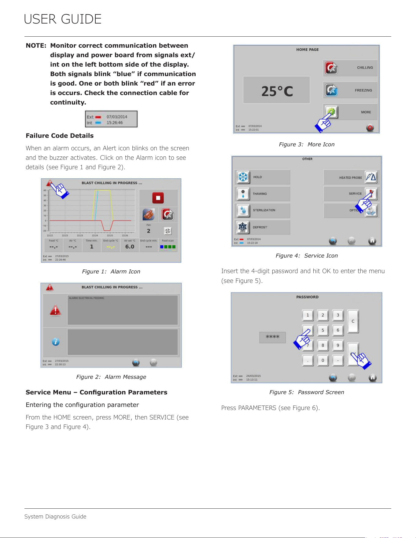
USER GUIDE
System Diagnosis Guide
NOTE: Monitor correct communication between
display and power board from signals ext/
int on the left bottom side of the display.
Both signals blink “blue” if communication
is good. One or both blink “red” if an error
is occurs. Check the connection cable for
continuity.
Failure Code Details
When an alarm occurs, an Alert icon blinks on the screen
and the buzzer activates. Click on the Alarm icon to see
details (see Figure 1 and Figure 2).
Figure 1: Alarm Icon
Figure 2: Alarm Message
Service Menu – Conguration Parameters
Entering the conguration parameter
From the HOME screen, press MORE, then SERVICE (see
Figure 3 and Figure 4).
Figure 3: More Icon
Figure 4: Service Icon
Insert the 4‑digit password and hit OK to enter the menu
(see Figure 5).
Figure 5: Password Screen
Press PARAMETERS (see Figure 6).
41
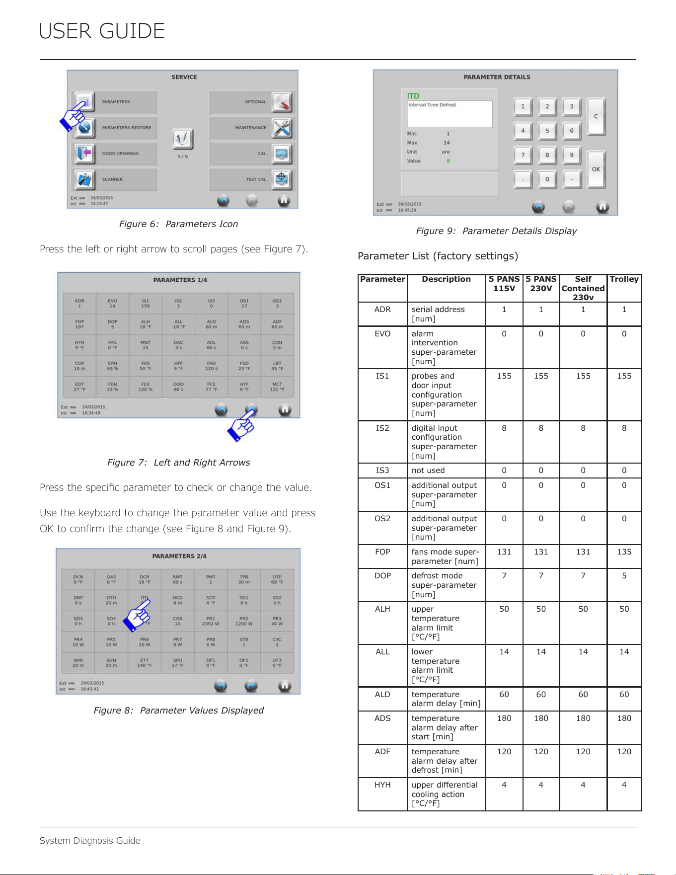
USER GUIDE
System Diagnosis Guide
Figure 6: Parameters Icon
Press the left or right arrow to scroll pages (see Figure 7).
Figure 7: Left and Right Arrows
Press the specic parameter to check or change the value.
Use the keyboard to change the parameter value and press
OK to conrm the change (see Figure 8 and Figure 9).
Figure 8: Parameter Values Displayed
Figure 9: Parameter Details Display
Parameter List (factory settings)
Parameter Description 5 PANS
115V
5 PANS
230V
Self
Contained
230v
Trolley
ADR serial address
[num]
1 1 1 1
EVO alarm
intervention
super-parameter
[num]
0 0 0 0
IS1 probes and
door input
conguration
super-parameter
[num]
155 155 155 155
IS2 digital input
conguration
super-parameter
[num]
8 8 8 8
IS3 not used 0 0 0 0
OS1 additional output
super-parameter
[num]
0 0 0 0
OS2 additional output
super-parameter
[num]
0 0 0 0
FOP fans mode super-
parameter [num]
131 131 131 135
DOP defrost mode
super-parameter
[num]
7 7 7 5
ALH upper
temperature
alarm limit
[°C/°F]
50 50 50 50
ALL lower
temperature
alarm limit
[°C/°F]
14 14 14 14
ALD temperature
alarm delay [min]
60 60 60 60
ADS temperature
alarm delay after
start [min]
180 180 180 180
ADF temperature
alarm delay after
defrost [min]
120 120 120 120
HYH upper dierential
cooling action
[°C/°F]
4 4 4 4
42
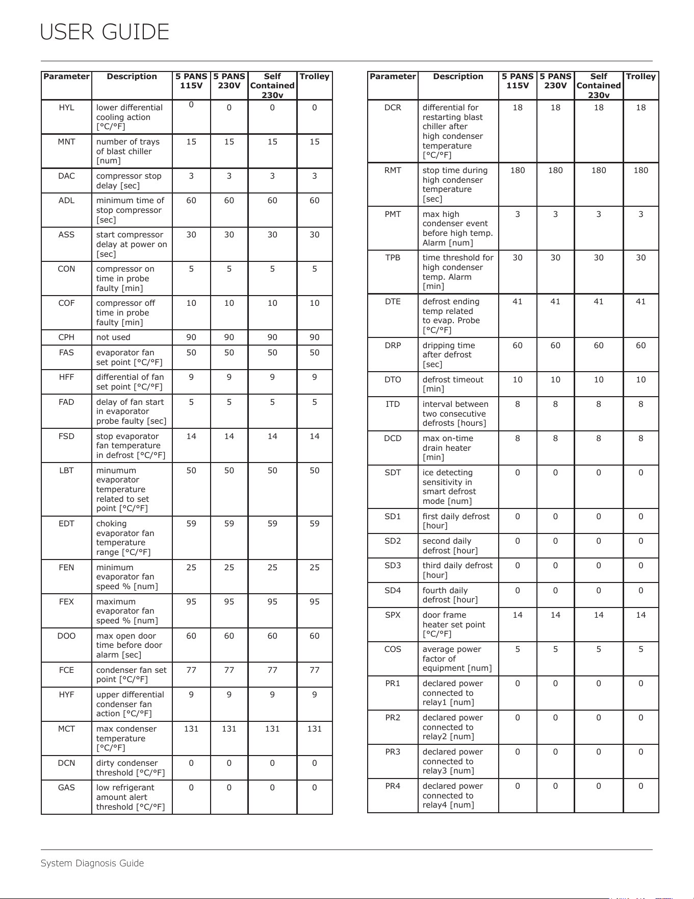
USER GUIDE
System Diagnosis Guide
Parameter Description 5 PANS
115V
5 PANS
230V
Self
Contained
230v
Trolley
HYL lower dierential
cooling action
[°C/°F]
0
0 0 0
MNT number of trays
of blast chiller
[num]
15 15 15 15
DAC compressor stop
delay [sec]
3 3 3 3
ADL minimum time of
stop compressor
[sec]
60 60 60 60
ASS start compressor
delay at power on
[sec]
30 30 30 30
CON compressor on
time in probe
faulty [min]
5 5 5 5
COF compressor o
time in probe
faulty [min]
10 10 10 10
CPH not used 90 90 90 90
FAS evaporator fan
set point [°C/°F]
50 50 50 50
HFF dierential of fan
set point [°C/°F]
9 9 9 9
FAD delay of fan start
in evaporator
probe faulty [sec]
5 5 5 5
FSD stop evaporator
fan temperature
in defrost [°C/°F]
14 14 14 14
LBT minumum
evaporator
temperature
related to set
point [°C/°F]
50 50 50 50
EDT choking
evaporator fan
temperature
range [°C/°F]
59 59 59 59
FEN minimum
evaporator fan
speed % [num]
25 25 25 25
FEX maximum
evaporator fan
speed % [num]
95 95 95 95
DOO max open door
time before door
alarm [sec]
60 60 60 60
FCE condenser fan set
point [°C/°F]
77 77 77 77
HYF upper dierential
condenser fan
action [°C/°F]
9 9 9 9
MCT max condenser
temperature
[°C/°F]
131 131 131 131
DCN dirty condenser
threshold [°C/°F]
0 0 0 0
GAS low refrigerant
amount alert
threshold [°C/°F]
0 0 0 0
Parameter Description 5 PANS
115V
5 PANS
230V
Self
Contained
230v
Trolley
DCR dierential for
restarting blast
chiller after
high condenser
temperature
[°C/°F]
18 18 18 18
RMT stop time during
high condenser
temperature
[sec]
180 180 180 180
PMT max high
condenser event
before high temp.
Alarm [num]
3 3 3 3
TPB time threshold for
high condenser
temp. Alarm
[min]
30 30 30 30
DTE defrost ending
temp related
to evap. Probe
[°C/°F]
41 41 41 41
DRP dripping time
after defrost
[sec]
60 60 60 60
DTO defrost timeout
[min]
10 10 10 10
ITD interval between
two consecutive
defrosts [hours]
8 8 8 8
DCD max on-time
drain heater
[min]
8 8 8 8
SDT ice detecting
sensitivity in
smart defrost
mode [num]
0 0 0 0
SD1 rst daily defrost
[hour]
0 0 0 0
SD2 second daily
defrost [hour]
0 0 0 0
SD3 third daily defrost
[hour]
0 0 0 0
SD4 fourth daily
defrost [hour]
0 0 0 0
SPX door frame
heater set point
[°C/°F]
14 14 14 14
COS average power
factor of
equipment [num]
5 5 5 5
PR1 declared power
connected to
relay1 [num]
0 0 0 0
PR2 declared power
connected to
relay2 [num]
0 0 0 0
PR3 declared power
connected to
relay3 [num]
0 0 0 0
PR4 declared power
connected to
relay4 [num]
0 0 0 0
43
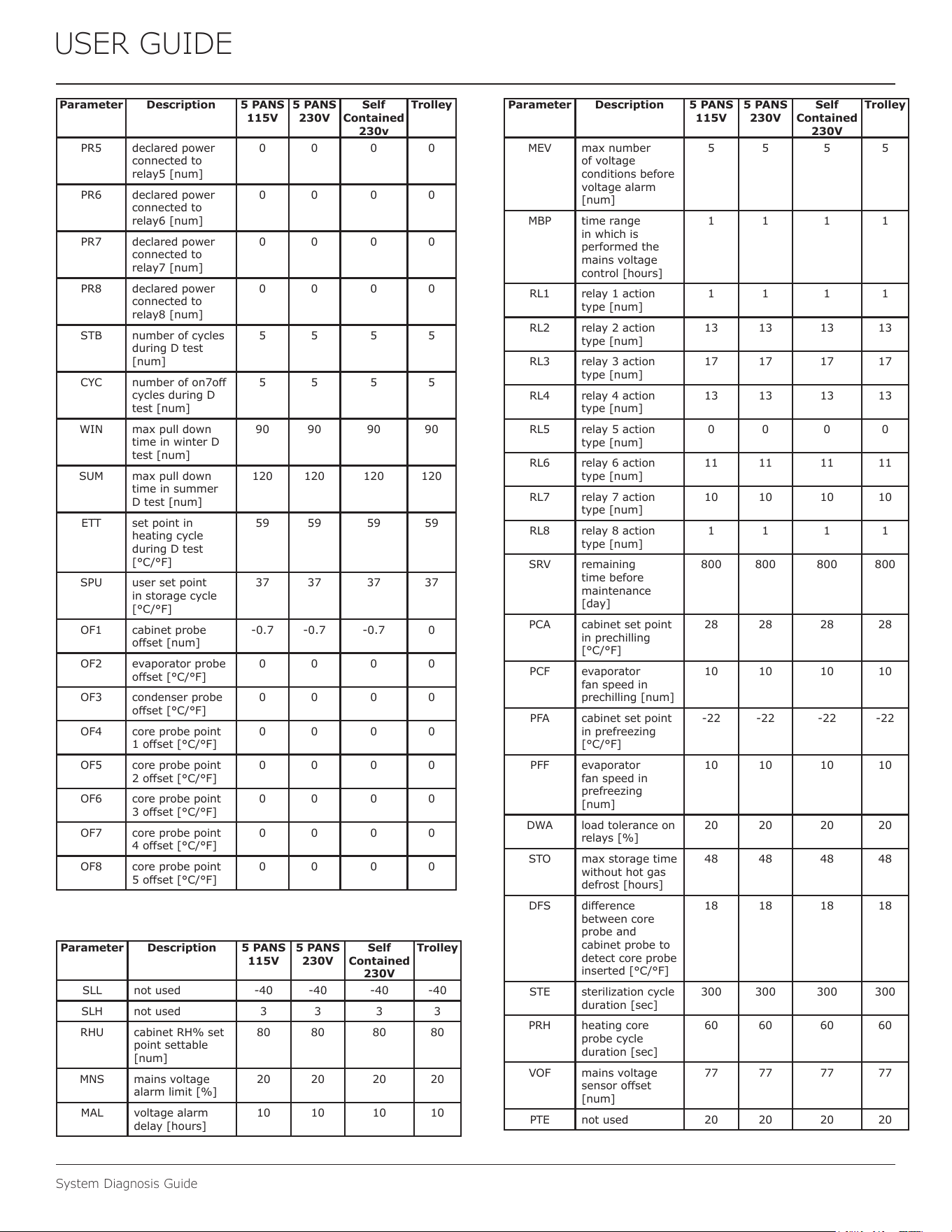
USER GUIDE
System Diagnosis Guide
Parameter Description 5 PANS
115V
5 PANS
230V
Self
Contained
230v
Trolley
PR5 declared power
connected to
relay5 [num]
0 0 0 0
PR6 declared power
connected to
relay6 [num]
0 0 0 0
PR7 declared power
connected to
relay7 [num]
0 0 0 0
PR8 declared power
connected to
relay8 [num]
0 0 0 0
STB number of cycles
during D test
[num]
5 5 5 5
CYC number of on7o
cycles during D
test [num]
5 5 5 5
WIN max pull down
time in winter D
test [num]
90 90 90 90
SUM max pull down
time in summer
D test [num]
120 120 120 120
ETT set point in
heating cycle
during D test
[°C/°F]
59 59 59 59
SPU user set point
in storage cycle
[°C/°F]
37 37 37 37
OF1 cabinet probe
oset [num]
-0.7 -0.7 -0.7 0
OF2 evaporator probe
oset [°C/°F]
0 0 0 0
OF3 condenser probe
oset [°C/°F]
0 0 0 0
OF4 core probe point
1 oset [°C/°F]
0 0 0 0
OF5 core probe point
2 oset [°C/°F]
0 0 0 0
OF6 core probe point
3 oset [°C/°F]
0 0 0 0
OF7 core probe point
4 oset [°C/°F]
0 0 0 0
OF8 core probe point
5 oset [°C/°F]
0 0 0 0
Parameter Description 5 PANS
115V
5 PANS
230V
Self
Contained
230V
Trolley
SLL not used -40 -40 -40 -40
SLH not used 3 3 3 3
RHU cabinet RH% set
point settable
[num]
80 80 80 80
MNS mains voltage
alarm limit [%]
20 20 20 20
MAL voltage alarm
delay [hours]
10 10 10 10
Parameter Description 5 PANS
115V
5 PANS
230V
Self
Contained
230V
Trolley
MEV max number
of voltage
conditions before
voltage alarm
[num]
5 5 5 5
MBP time range
in which is
performed the
mains voltage
control [hours]
1 1 1 1
RL1 relay 1 action
type [num]
1 1 1 1
RL2 relay 2 action
type [num]
13 13 13 13
RL3 relay 3 action
type [num]
17 17 17 17
RL4 relay 4 action
type [num]
13 13 13 13
RL5 relay 5 action
type [num]
0 0 0 0
RL6 relay 6 action
type [num]
11 11 11 11
RL7 relay 7 action
type [num]
10 10 10 10
RL8 relay 8 action
type [num]
1 1 1 1
SRV remaining
time before
maintenance
[day]
800 800 800 800
PCA cabinet set point
in prechilling
[°C/°F]
28 28 28 28
PCF evaporator
fan speed in
prechilling [num]
10 10 10 10
PFA cabinet set point
in prefreezing
[°C/°F]
-22 -22 -22 -22
PFF evaporator
fan speed in
prefreezing
[num]
10 10 10 10
DWA load tolerance on
relays [%]
20 20 20 20
STO max storage time
without hot gas
defrost [hours]
48 48 48 48
DFS dierence
between core
probe and
cabinet probe to
detect core probe
inserted [°C/°F]
18 18 18 18
STE sterilization cycle
duration [sec]
300 300 300 300
PRH heating core
probe cycle
duration [sec]
60 60 60 60
VOF mains voltage
sensor oset
[num]
77 77 77 77
PTE not used 20 20 20 20
44
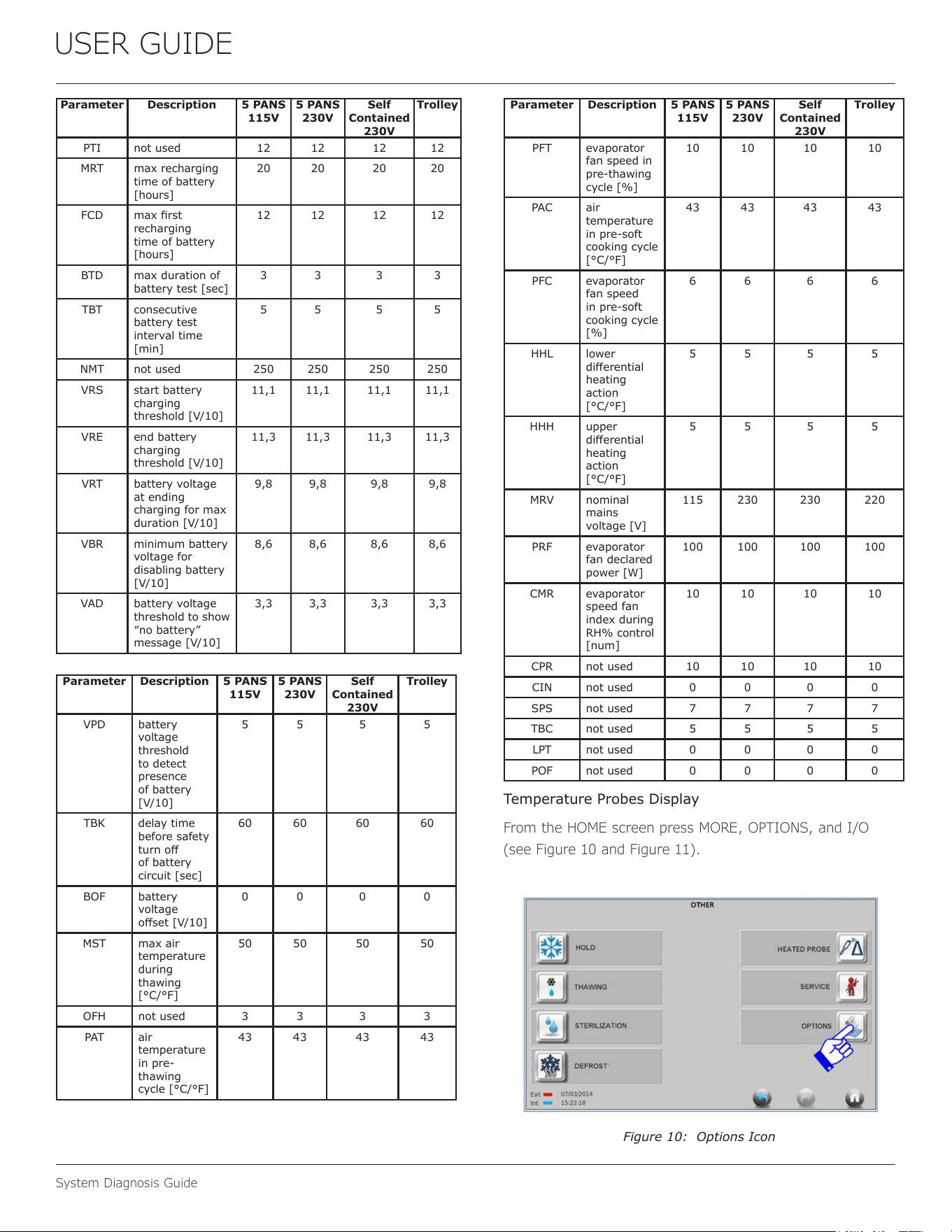
USER GUIDE
System Diagnosis Guide
Parameter Description 5 PANS
115V
5 PANS
230V
Self
Contained
230V
Trolley
PTI not used 12 12 12 12
MRT max recharging
time of battery
[hours]
20 20 20 20
FCD max rst
recharging
time of battery
[hours]
12 12 12 12
BTD max duration of
battery test [sec]
3 3 3 3
TBT consecutive
battery test
interval time
[min]
5 5 5 5
NMT not used 250 250 250 250
VRS start battery
charging
threshold [V/10]
11,1 11,1 11,1 11,1
VRE end battery
charging
threshold [V/10]
11,3 11,3 11,3 11,3
VRT battery voltage
at ending
charging for max
duration [V/10]
9,8 9,8 9,8 9,8
VBR minimum battery
voltage for
disabling battery
[V/10]
8,6 8,6 8,6 8,6
VAD battery voltage
threshold to show
“no battery”
message [V/10]
3,3 3,3 3,3 3,3
Parameter Description 5 PANS
115V
5 PANS
230V
Self
Contained
230V
Trolley
VPD battery
voltage
threshold
to detect
presence
of battery
[V/10]
5 5 5 5
TBK delay time
before safety
turn o
of battery
circuit [sec]
60 60 60 60
BOF battery
voltage
oset [V/10]
0 0 0 0
MST max air
temperature
during
thawing
[°C/°F]
50 50 50 50
OFH not used 3 3 3 3
PAT air
temperature
in pre-
thawing
cycle [°C/°F]
43 43 43 43
Parameter Description 5 PANS
115V
5 PANS
230V
Self
Contained
230V
Trolley
PFT evaporator
fan speed in
pre-thawing
cycle [%]
10 10 10 10
PAC air
temperature
in pre-soft
cooking cycle
[°C/°F]
43 43 43 43
PFC evaporator
fan speed
in pre-soft
cooking cycle
[%]
6 6 6 6
HHL lower
dierential
heating
action
[°C/°F]
5 5 5 5
HHH upper
dierential
heating
action
[°C/°F]
5 5 5 5
MRV nominal
mains
voltage [V]
115 230 230 220
PRF evaporator
fan declared
power [W]
100 100 100 100
CMR evaporator
speed fan
index during
RH% control
[num]
10 10 10 10
CPR not used 10 10 10 10
CIN not used 0 0 0 0
SPS not used 7 7 7 7
TBC not used 5 5 5 5
LPT not used 0 0 0 0
POF not used 0 0 0 0
Temperature Probes Display
From the HOME screen press MORE, OPTIONS, and I/O
(see Figure 10 and Figure 11).
Figure 10: Options Icon
45
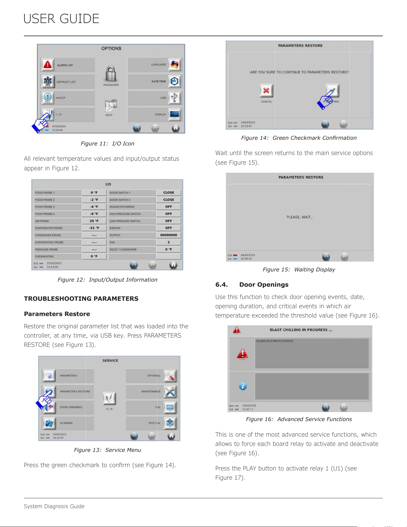
USER GUIDE
System Diagnosis Guide
Figure 11: I/O Icon
All relevant temperature values and input/output status
appear in Figure 12.
Figure 12: Input/Output Information
TROUBLESHOOTING PARAMETERS
Parameters Restore
Restore the original parameter list that was loaded into the
controller, at any time, via USB key. Press PARAMETERS
RESTORE (see Figure 13).
Figure 13: Service Menu
Press the green checkmark to conrm (see Figure 14).
Figure 14: Green Checkmark Conrmation
Wait until the screen returns to the main service options
(see Figure 15).
Figure 15: Waiting Display
6.4. Door Openings
Use this function to check door opening events, date,
opening duration, and critical events in which air
temperature exceeded the threshold value (see Figure 16).
Figure 16: Advanced Service Functions
This is one of the most advanced service functions, which
allows to force each board relay to activate and deactivate
(see Figure 16).
Press the PLAY button to activate relay 1 (U1) (see
Figure 17).
46
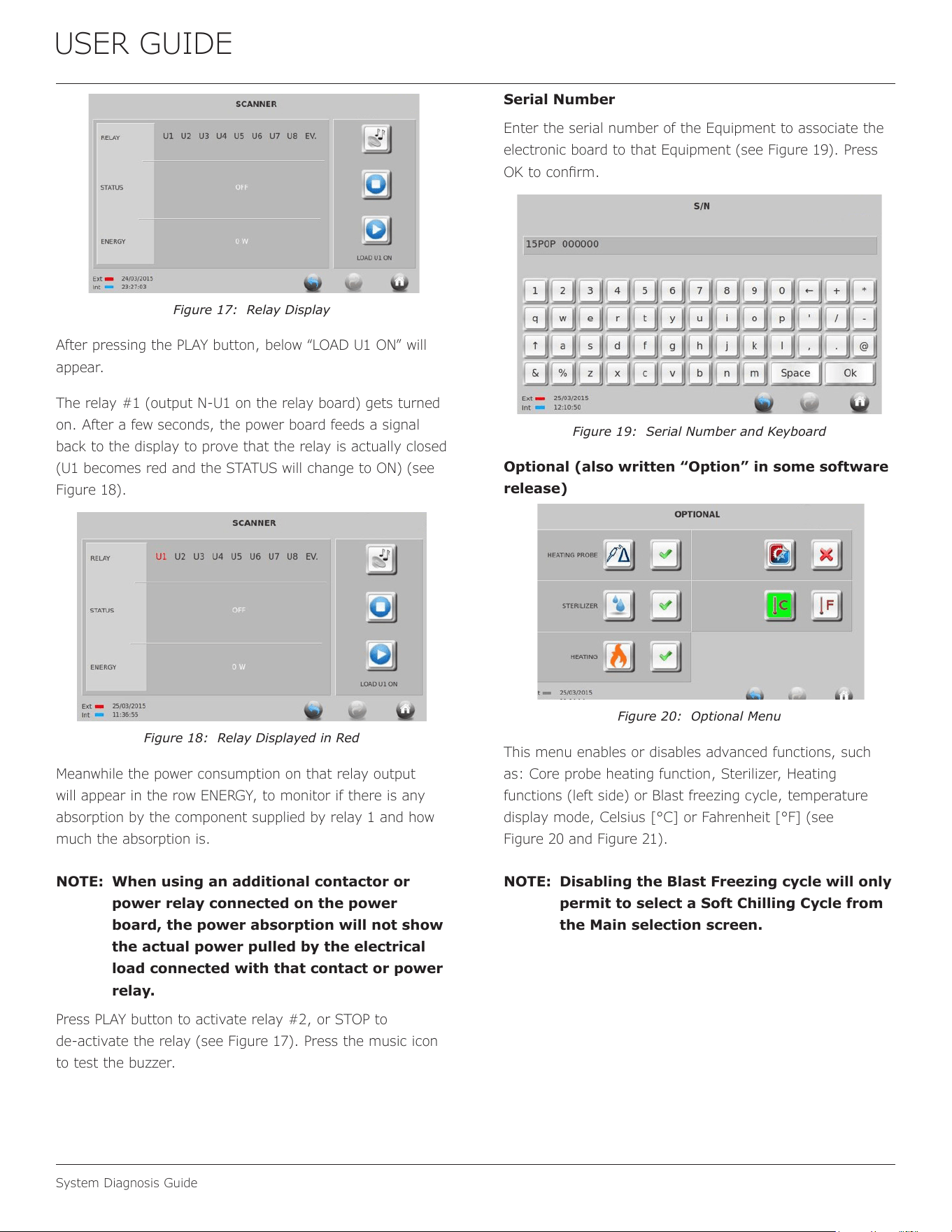
USER GUIDE
System Diagnosis Guide
Figure 17: Relay Display
After pressing the PLAY button, below “LOAD U1 ON” will
appear.
The relay #1 (output N‑U1 on the relay board) gets turned
on. After a few seconds, the power board feeds a signal
back to the display to prove that the relay is actually closed
(U1 becomes red and the STATUS will change to ON) (see
Figure 18).
Figure 18: Relay Displayed in Red
Meanwhile the power consumption on that relay output
will appear in the row ENERGY, to monitor if there is any
absorption by the component supplied by relay 1 and how
much the absorption is.
NOTE: When using an additional contactor or
power relay connected on the power
board, the power absorption will not show
the actual power pulled by the electrical
load connected with that contact or power
relay.
Press PLAY button to activate relay #2, or STOP to
de‑activate the relay (see Figure 17). Press the music icon
to test the buzzer.
Serial Number
Enter the serial number of the Equipment to associate the
electronic board to that Equipment (see Figure 19). Press
OK to conrm.
Figure 19: Serial Number and Keyboard
Optional (also written “Option” in some software
release)
Figure 20: Optional Menu
This menu enables or disables advanced functions, such
as: Core probe heating function, Sterilizer, Heating
functions (left side) or Blast freezing cycle, temperature
display mode, Celsius [°C] or Fahrenheit [°F] (see
Figure 20 and Figure 21).
NOTE: Disabling the Blast Freezing cycle will only
permit to select a Soft Chilling Cycle from
the Main selection screen.
47
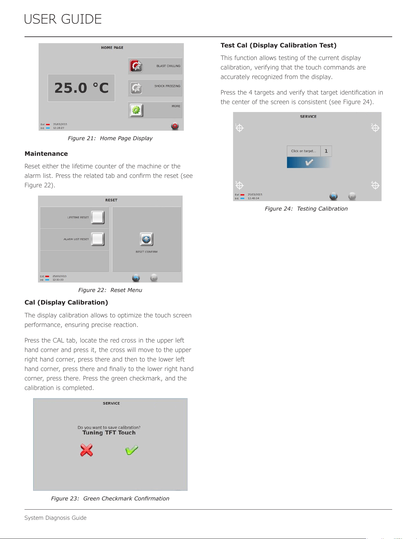
USER GUIDE
System Diagnosis Guide
Figure 21: Home Page Display
Maintenance
Reset either the lifetime counter of the machine or the
alarm list. Press the related tab and conrm the reset (see
Figure 22).
Figure 22: Reset Menu
Cal (Display Calibration)
The display calibration allows to optimize the touch screen
performance, ensuring precise reaction.
Press the CAL tab, locate the red cross in the upper left
hand corner and press it, the cross will move to the upper
right hand corner, press there and then to the lower left
hand corner, press there and nally to the lower right hand
corner, press there. Press the green checkmark, and the
calibration is completed.
Figure 23: Green Checkmark Conrmation
Test Cal (Display Calibration Test)
This function allows testing of the current display
calibration, verifying that the touch commands are
accurately recognized from the display.
Press the 4 targets and verify that target identication in
the center of the screen is consistent (see Figure 24).
Figure 24: Testing Calibration
48
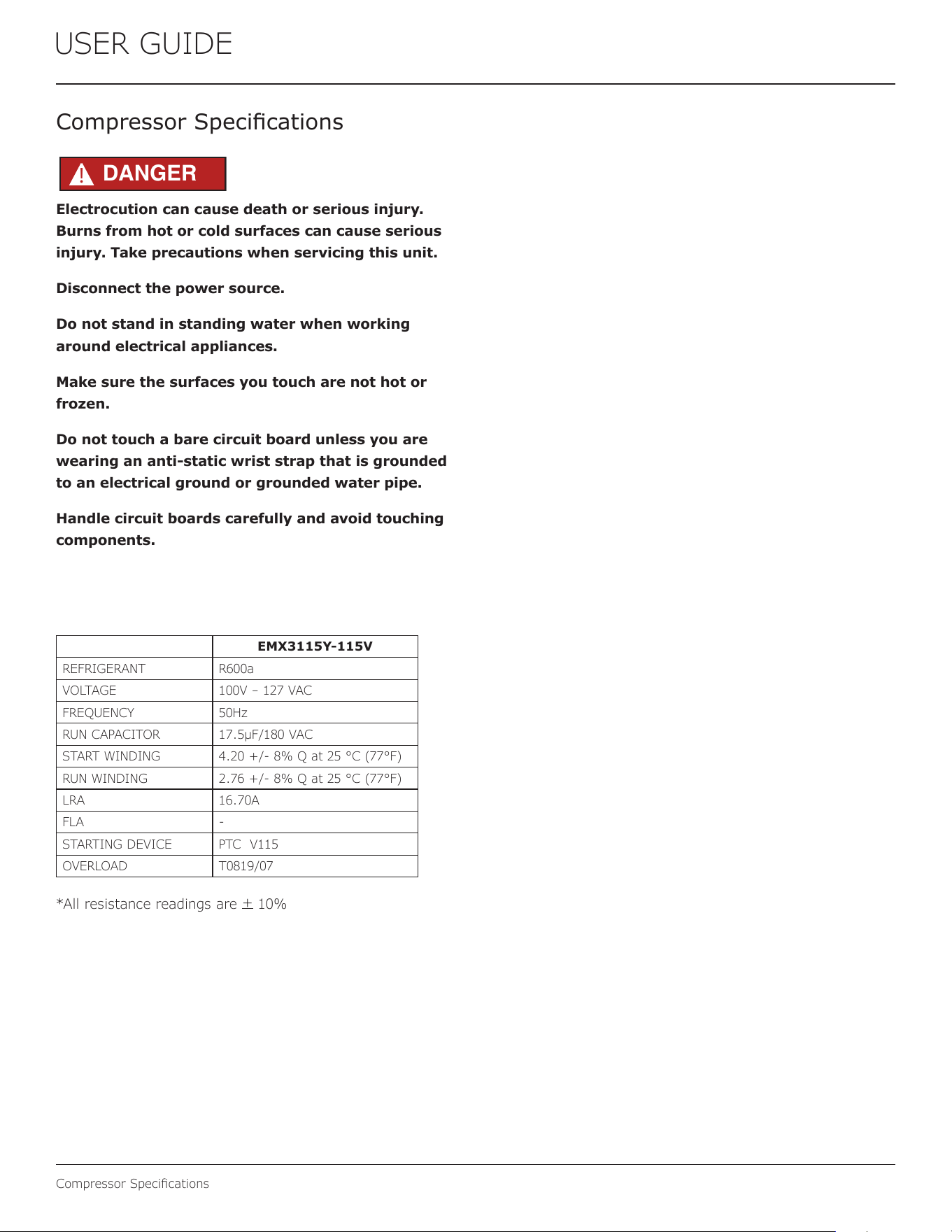
USER GUIDE
Compressor Specications
Electrocution can cause death or serious injury.
Burns from hot or cold surfaces can cause serious
injury. Take precautions when servicing this unit.
Disconnect the power source.
Do not stand in standing water when working
around electrical appliances.
Make sure the surfaces you touch are not hot or
frozen.
Do not touch a bare circuit board unless you are
wearing an anti-static wrist strap that is grounded
to an electrical ground or grounded water pipe.
Handle circuit boards carefully and avoid touching
components.
Compressor Specications
EMX3115Y-115V
REFRIGERANT R600a
VOLTAGE 100V – 127 VAC
FREQUENCY 50Hz
RUN CAPACITOR 17.5μF/180 VAC
START WINDING 4.20 +/- 8% Q at 25 °C (77°F)
RUN WINDING 2.76 +/- 8% Q at 25 °C (77°F)
LRA 16.70A
FLA -
STARTING DEVICE PTC V115
OVERLOAD T0819/07
*All resistance readings are
+
10%
DANGER
!
49
Copyright U-Line Corporation. All Rights Reserved. | Publication Number 30716 | 06/2025 Rev. C
U-Line Corporation (U-Line) Commercial Limited Warranty
Three Year Limited Warranty
For three years from the date of original purchase, this warranty covers all parts and labor to repair or replace any part of the product that
proves to be defective in materials or workmanship. Service provided by U-Line under the above warranty must be performed by a U-Line
factory authorized servicer, unless otherwise specified by U-Line. Service provided during normal business hours.
Five Year Compressor Limited Warranty
For five years from the date of original purchase, U-Line will replace the compressor, labor not included, that proves to be defective. All
service provided by U-Line under the above warranty must be performed by a U-Line factory authorized servicer, unless otherwise
specified by U-Line. Service provided during normal business hours.
Terms
These warranties apply only to products installed in any one of the fifty states of the United States, the District of Columbia, or the ten
provinces of Canada. The warranties do not cover any parts or labor to correct any defect caused by negligence, accident or improper use,
maintenance, installation, service, repair, acts of God, fire, flood or other natural disasters. The product must be installed, operated, and
maintained in accordance with your product’s User Guide.
The remedies described above for each warranty are the only ones that U-Line will provide, either under these warranties or under any
warranty arising by operation of law. U-Line will not be responsible for any consequential or incidental damages arising from the breach of
these warranties or any other warranty, whether express, implied, or statutory. Some states do not allow the exclusion or limitation of
incidental or consequential damages, so the above limitation or exclusion may not apply to you. These warranties give you specific legal
rights, and you may also have other rights which vary from state to state.
Any warranty that may be implied in connection with your purchase or use of the product, including any warranty of merchantability or any
warranty fit for a particular purpose is limited to the duration of these warranties, and only extends to five years in duration for the parts
described in the section related to the three-year limited warranty above. Some states do not allow limitations on how long an implied warranty
lasts, so the above limitations may not apply to you.
• Service must be dispatched by the factory to be eligible for warranty coverage.
• The warranties only apply to the original purchaser and are non-transferable.
• Replacement water filters, light bulbs, and other consumable parts are not covered by these warranties.
• The start of U-Line's obligation begins on the shipment date from the factory.
• Food, beverage, and medicine loss are not covered by these warranties.
• If the product is located in an area where U-Line factory authorized service is not available, you may be responsible for a trip
charge or you may be required to bring the product to a U-Line factory authorized service location at your own cost and
expense.
• Any product purchased as a floor display is covered by a 90-day warranty only.
• Signal issues related to Wi-Fi connectivity are not covered by these warranties.
For parts and service assistance, or to find U-Line factory authorized service near you, contact U-Line:
8900 N. 55
th
Street, Milwaukee, WI 53223 • u-line.com • onlineservice@u-line.com • +1.414.354.0300
50

