
EN

TABLE OF CONTENTS
INTRODUCTION...............................................................................................................................1
SAFETY.........................................................................................................................................2-9
UNPACKING...................................................................................................................................10
CONTROLS AND FEATURES........................................................................................................11
CONTROL PANEL FEATURES................................................................................................12-13
SPECIFICATIONS...........................................................................................................................14
CO WATCH-GUARD................................................................................................................15-16
OPERATION..............................................................................................................................17-27
MAINTENANCE AND STORAGE...........................................................................................28-33
TROUBLESHOOTING...................................................................................................................34
PARTS DIAGRAM AND PARTS LIST.....................................................................................35-40
CIRCUIT DIAGRAM........................................................................................................................41
WARRANTY.............................................................................................................................42-43
AIVOLT WARRANTY REGISTRATION FORM............................................................................44
EN
INTRODUCTION
1
Warranty limits and Implications
and Consequential Damages
AIVOLT is not obligated to cover any loss of
time, use of product, freight cost, or any
other incidental or consequential claim from
the use of this product.
This warranty is in Lieu of all other warran-
ties,express or implied.
This warranty gives you specific legal rights
which vary from state to state.
This product and other substances that may
become airborne from its use contain chemi-
cals, including lead, known to the State of
California to cause cancer, birth defects, or
other reproductive harm. Wash hands after
handling. For more information go to
www.P65warnings.ca.gov.
DISCLAIMERS
ALL RIGHTS RESERVED
UPDATES
PRODUCT REGISTRATION
For Your Records
Date of Purchase:
Model Number:
Serial Number:
Amazon Order Number:
For trouble-free warranty coverage, it is
important to register your AIVOLT product.
You can register by:
• Registering your product on-line at:
aivolt group.com/pages/warranty-regis-
tration.
• Scanning the above QR code with your
smartphone camera to be directed to the
mobile registration link.
All information, illustrations, and specifica-
tions in this manual were in effect at the
time of publishing. The illustrations used in
this manual are intended as representative
reference views only. We reserve the right to
make any specification or design change
without notice.
The latest User Manual for your AIVOLT
products can be found under our support
tab, https://www.aivoltgroup.com/manuals.
Or scan the following QR code with your
smartphone camera to be directed to the
link.
All rights reserved. No reproduction allowed
in any form without written permission from
AivoltGroup Limited Company.
DANGER
!
Read this manual before using or
performing maintenance on this
product. Failure to follow the
instructions and safety precautions
in this manual can result in serious
injury or death.
IMPORTANT: Keep your purchase receipt
for trouble-free warranty coverage.
NOTICE
Thank you for choosing AIVOLT! PLEASE
READ BEFORE RETURNING THIS PRODUCT
FOR ANY REASON.
If you have a question or experience a prob-
lem with your AIVOLT purchase, call us at
+1 (689) 888-7131 or contact us customer
to speak with an agent. SAVE THIS MANUAL
FOR FUTURE REFERENCE.
HAVE QUESTIONS ?
Email us a t contact-us@aivoltgroup .com
or call +1 (689) 888-7131
WARNING
EN
For trouble-free warranty coverage, it is
important to register your AIVOLT product.
You can register by:
• Registering your product on-line at:
aivolt group.com/pages/warranty-regis-
tration.
• Scanning the above QR code with your
smartphone camera to be directed to the
mobile registration link.
Registering your product on-line at:
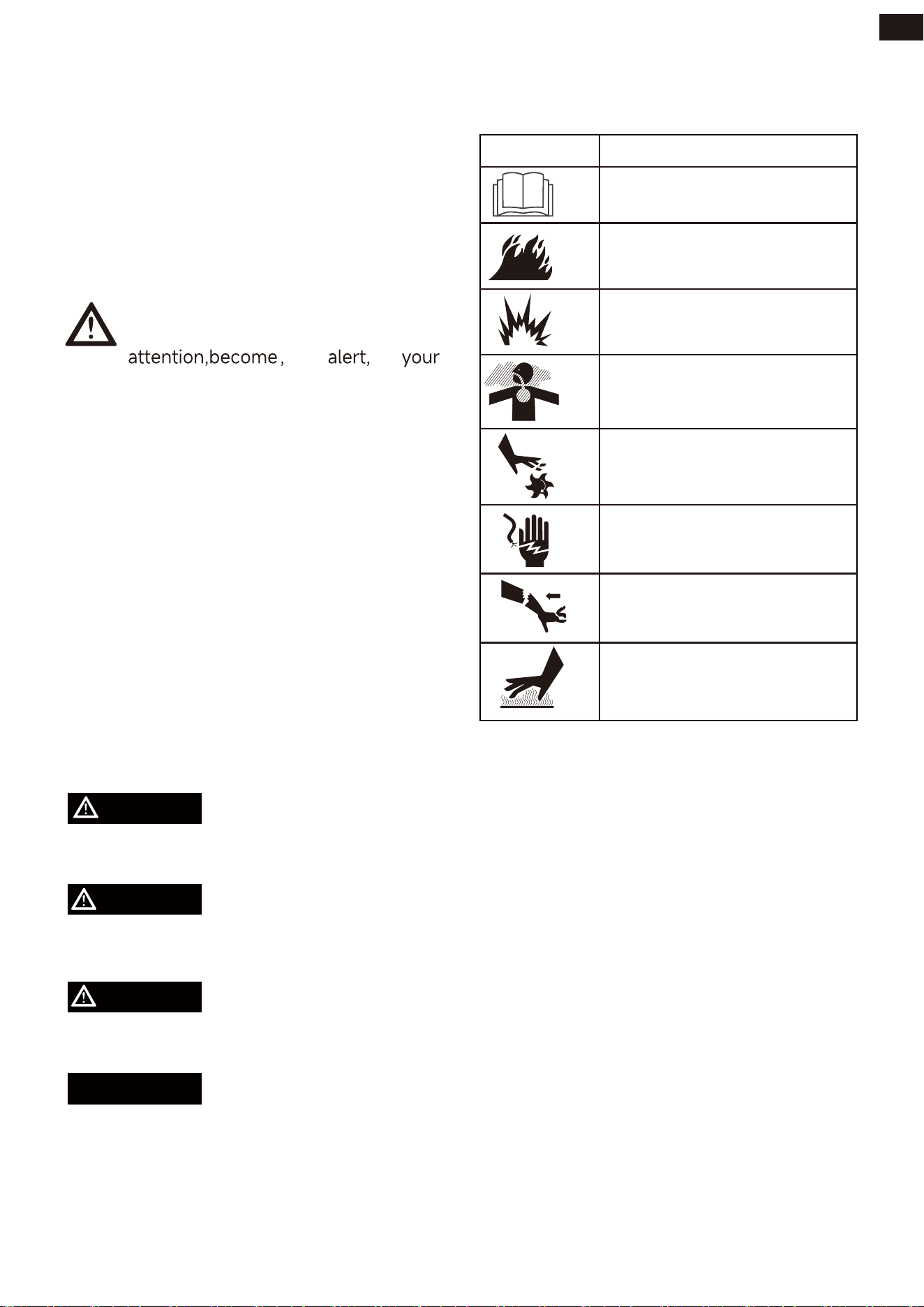
SAFETY
Asphyxiation Hazard
Fire Hazard
Hot Surface.
Do Not Touch the Surface.
Burn Hazard
Kickback
Electric Shock Hazard
Explosion Hazard
Moving Parts Hazard
Operator’s Manual
Symbol Description
2
Registering your product on-line at:
The words DANGER, WARNING, CAUTION,
and NOTICE are used throughout this
manual to highlight important information.
Make sure that the meanings of this safety
information is known to all who operate, per-
form maintenance on, or are near the gener-
ator.
DEFINITIONS AND SYMBOLS
The manufacturer cannot possibly anticipate
every possible circumstance that might
involve a hazard. The warnings in this
manual and the tags and decals affixed to
the unit are therefore not all-inclusive. If you
use a procedure, work method or operating
technique that the manufacturer does not
specifically recommend you must satisfy
yourself that it is safe for you and others.
You must also make sure that the procedure
work method or operating technique that
you choose does not render the generator
unsafe.
WARNING
DANGER
CAUTION
Indicates a hazard which, if not avoided,will
result in death or serious injury.
Indicates a hazard which, if not avoied, could
result in death or serious injury.
Indicates a hazard which, if not avoided,
could result in minor or moderate injury.
Indicates information considered important,
but not haard-related (e.g.,messages relat-
ing to property damage).
NOTICE
This safety alert symbol appears with
most safety statements. It means
safety is involved! Please read and
abide by the message that follows
the safety alerts symbol.
EN
SAFETY
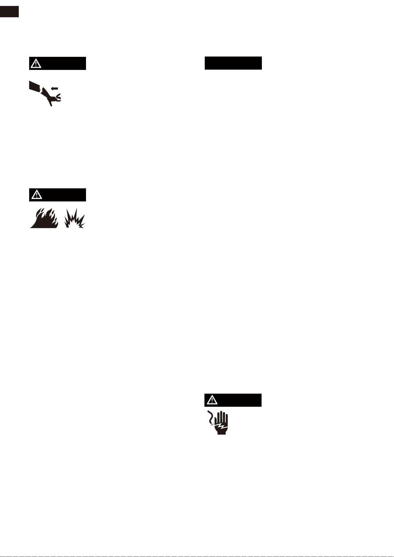
GENERAL SAFETY PRECAUTIONS
POISONOUS GAS HAZARD
DANGER
•Engine exhaust contains
carbon monoxide, a poisonous
gas that could kill you in minutes.
You CANNOT smell it,see it,or taste it. Even
if you do not smell exhaust fumes, you could
still be exposed to carbon
monoxide gas.
•The exhaust system must be properly
maintained.Do not alter or modify the
exhaust system as to render it unsafe or
make it noncompliant with local codes
and/or standards. Failure to do so will result
in death or serious injury.
WARNING
WARNING
Always, install battery operated
carbon monoxide alarm indoors
and installed according to the
manufacturer’s instruction.
• Operate this product ONLY outside far
away from windows, doors and vents to
reduce the risk of carbon monoxide gas from
accumulating and potentially being drawn
towards occupied spaces.DO NOT run this
product inside homes, garages, basements,
crawl spaces, sheds, or other partially-en-
closed spaces even if using fans or opening
doors and windows for ventilation. Carbon
monoxide can quickly build up in these
spaces and can linger for hours, even after
this product has shut off.
• ALWAYS place this product downwind
and point the engine exhaust away from
occupied spaces. If you start to feel sick,
dizzy, or weak while using this product, shut
it off and get to fresh air RIGHT AWAY. See a
doctor. You may have carbon monoxide poi-
soning.
If you start to feel sick, dizzy or weak while
using the portable generator, you may have
carbon monoxide poisoning. Get out side to
fresh air immediately and call helpline for
emergency medical attention. Very high
levels of CO can rapidly cause victims to
lose consciousness before they can rescue
themselves. DO NOT attempt to shut off the
generator before moving to fresh air. Enter-
ing an enclosed space where a generator is
or has been running may put you at greater
risk of CO poisoning.
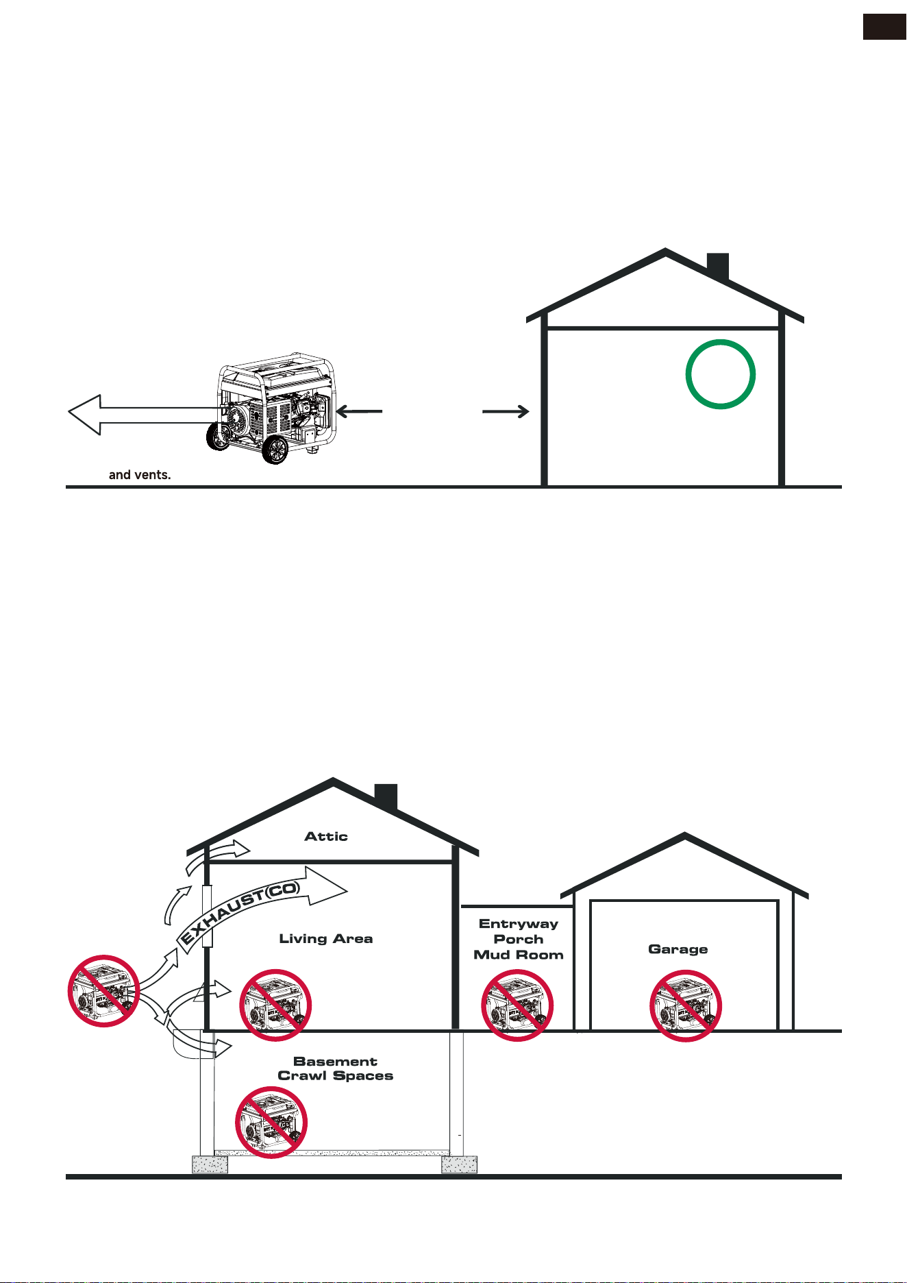
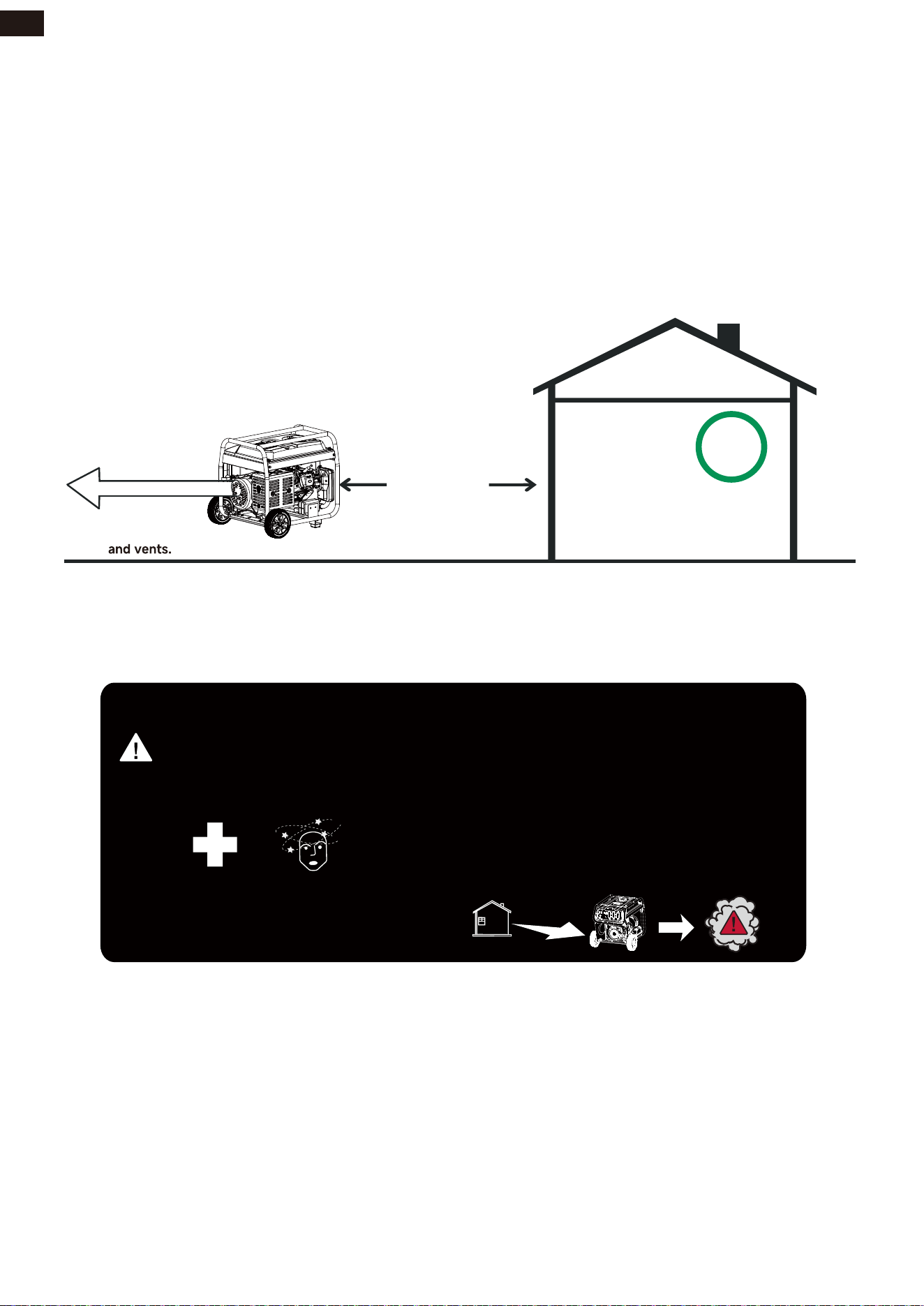
Avoid other generator hazards. READ MANUAL BEFORE USE.
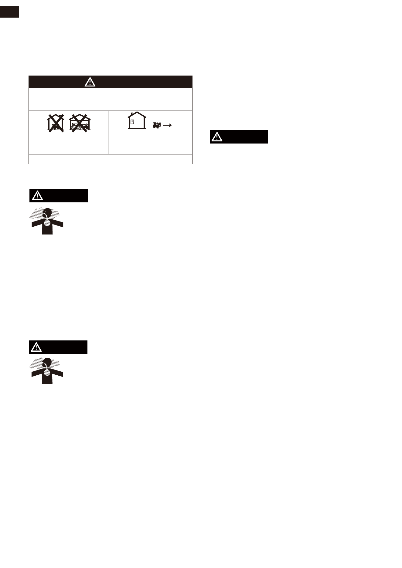
DANGER
Using a generator indoors CAN KILL YOU IN MINUTES.
Generator exhaust contains carbon monoxide. This is a poison
you cannot see or smell.
Only use OUTSIDE and
far away from windows,
doors and vents.
NEVER use inside a home
or garage, EVEN IF doors
and windows are open.
3
EN
SAFETY
• ONLY use outside and downwind, far away from windows, doors and vents.
• Direct exhaust away from occupied spaces.
CORRECT USAGE
INCORRECT USAGE
Example location to reduce risk of carbon monoxide poisoning
EXHAUST[CO]
KEEP
FAR AWAY
• Near any door, window or vent
• Garage
• Basement
• Crawl Space
• Living Area
• Attic
• Entry Way
• Porch
• Mud Room
Do not operate in any of the following locations:
CO Detector
in Living Areas
Direct exhaust
AWAY from
windows, doors,
Only use OUTSlDE and
FAR AWAY from windows,
doors and vents.
4
EN
SAFETY
WHEN ADDING OR DRAINING FUEL
WARNING
DANGER
DANGER
NOTICE
Starter cord kickback (rapid
retraction) will pull hand and arm
toward engine faster than you can
let go which could cause broken
bones, fractures, bruises, or
sprains resulting in serious injury.
• When starting engine, pull cord slowly
until resistance is felt and then pull rapid-
ly to avoid kickback.
• NEVER start or stop engine with electri-
cal devices plugged in and turned on.
• Fuel and its vapor are extremely flamma-
ble and explosive. Add fuel in a well ven-
tilated area. Keep sparks, open flames
and other ignition sources away. Failure
to do so will result in death and serious
injury.
• Do not overfill tank. Allow space for fuel
expansion. If fuel spills wait until it evapo-
rates before starting engine. Failure to do
so will result in death and serious injury.
• Turn generator engine OFF and let it cool
at least 2 minutes before removing fuel
cap. Loosen cap slowly to relieve pres-
sure in tank.
• Fill or drain fuel tank outdoors.
• DO NOT overfill tank. Allow space for
fuel expansion.
• If fuel spills, wait until it evaporates
before starting engine.
• Keep fuel away from sparks, open
flames, pilot lights, heat, and other igni-
tion sources.
• Check fuel lines, tank, cap, and fittings
frequently for cracks or leaks. Replace if
necessary.
• DO NOT light a cigarette or smoke.
WHEN STARTING EQUIPMENT
• Ensure spark plug, muffler, fuel cap, and
air cleaner are in place.
• DO NOT crank engine with spark plug
removed.
• DO NOT operate this product inside any
building, carport, porch, mobile equip-
ment, marine applications, or enclosure.
• DO NOT tip engine or equipment at
angle which causes fuel to spill.
• DO NOT stop engine by moving choke
control to “Start” position.
• Transport/move/repair with fuel tank
EMPTY or with fuel shutoff valve OFF.
• DO NOT tip engine or equipment at
angle which causes fuel to spill.
• Disconnect spark plug wire.
WHEN OPERATING EQUIPMENT
WHEN TRANSPORTING, MOVING OR
REPAIRING EQUIPMENT
WHEN STORING FUEL OR EQUIPMENT
WITH FUEL IN TANK
• Store away from furnaces, stoves, water
heaters, clothes dryers, or other appli-
ances that have pilot light or other igni-
tion source because they could ignite
fuel vapors.
• Generator voltage could cause
electrical shock or burn will result
in death or serious injury.
• Never use generator in wet or damp
locations. Never expose generator to
rain, snow, water spray while in use. Pro-
tect generator from all hazardous weath-
er conditions. Moisture, or ice can cause
a short circuit or other malfunction in the
electric circuit. Water contact with a
power source if not avoided, will result in
death or serious injury.
5
EN
DO NOT lay the generator on its side when
moving, storing or operating. Oil may leak
and damage the engine or your property.
SAFETY
WARNING
WARNING
WARNING
DANGER
DANGER
CAUTION
Fire and electrocution hazard. Do not con-
nect to a building's electrical system unless
the generator and transfer switch have been
properly installed and the electrical output
has been verified by a qualified electrician.
The connection must isolate the generator
power from utility power and must comply
with all applicable laws and electrical codes.
• Use a ground fault circuit interrupter
(GFCI) in any damp or highly conductive
area, such as metal decking or steel work.
• DO NOT use generator with electrical
cords which are worn, frayed, bare or
otherwise damaged.
• DO NOT allow unqualified persons or
children to operate or service generator.
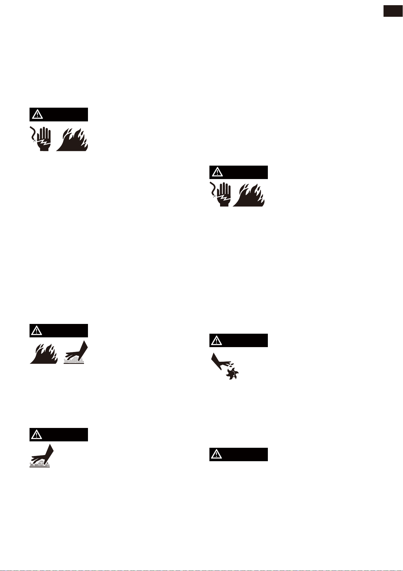
Exhaust heat/gases could ignite combusti-
bles,structures or damage fuel tank causing
a fire,resulting in death or serious injury.
Contact with muffler area could cause burns
resulting in serious injury.
When operating machine, do not
touch hot surfaces. Keep machine
away from combustibles during
use. Hot surfaces could result in
severe burns or fire.
• Allow equipment to cool before touching.
• Replacement parts must be the same and
installed in the same position as the origi-
nal parts.
• It is a violation of California Public
Resource Code, Section 4442, to use or
operate the engine on any forest-cov-
ered, brush-covered, or grass-covered
land unless the exhaust system is
equipped with a spark arrester, as
defined in Section 4442, maintained in
effective working order. Other states or
federal jurisdictions may have similar
laws.
Unintentional sparking could
cause fire or electric shock
resulting in death or serious
injury.
WHEN ADJUSTING OR MAKING REPAIRS
TO YOUR GENERATOR
• Disconnect the spark plug wire from the
spark plug and place the wire where it
cannot contact spark plug.
WHEN TESTING FOR ENGINE SPARK
• Use approved spark plug tester.
• DO NOT check for spark with spark plug
removed.
Starter and other rotating parts
could entangle hands, hair, cloth-
ing, or accessories. Keep away
from rotating parts, failure to do so
could result in death or serious
injury.
• DO NOT wear loose clothing, jewelry or
anything that could be caught in the
starter or other rotating parts.
Excessively high operating speeds could
result in minor injury. Excessively low oper-
ating speeds impose a heavy load.
6
EN
• Contact with terminals, bare wires and
electrical connections when generator is
running will result in death or serious
injury.

SAFETY
• DO NOT tamper with governor spring,
links or other parts to increase engine
speed. Generator supplies correct rated
frequency and voltage when running at
governed speed.
• DO NOT modify generator in any way.
NOTICE
WARNING
Exceeding generators wattage/amperage
capacity could damage generator and/or
electrical devices connected to it.
NOTICE
Improper treatment of generator could
damage it and shorten its life.
• DO NOT exceed the generator’s wattage
amperage capacity.
• Start generator and let engine stabilize
before connecting electrical loads.
• Connect electrical loads in OFF position,
then turn ON for operation.
• Turn electrical loads OFF and disconnect
from generator before stopping genera-
tor.
• Use generator only for intended uses.
• If you have questions about intended
use, ask dealer or contact local service
center.
• Operate generator only on level surfaces.
• DO NOT expose generator to excessive
moisture, dust, dirt, or corrosive vapors.
• DO NOT insert any objects through cool-
ing slots.
• If connected devices overheat, turn them
off and disconnect them from generator.
• Shut off generator if:
-Electrical output is lost.
-Equipment sparks, smokes, or emits
flames.
-Unit vibrates excessively.
Medical and Life Support Uses.
• In case of emergency, call helpline
immediately.
• NEVER use this product to power life
support devices or life support applianc-
es.
• NEVER use this product to power medi-
cal devices or medical appliances.
• Inform your electricity provider immedi-
ately if you or anyone in your household
depends on electrical equipment to live.
• Inform your electrical provider immedi-
ately if a loss of power would cause you
or anyone in your household to experi-
ence a medical emergency.
7
EN
SAFETY
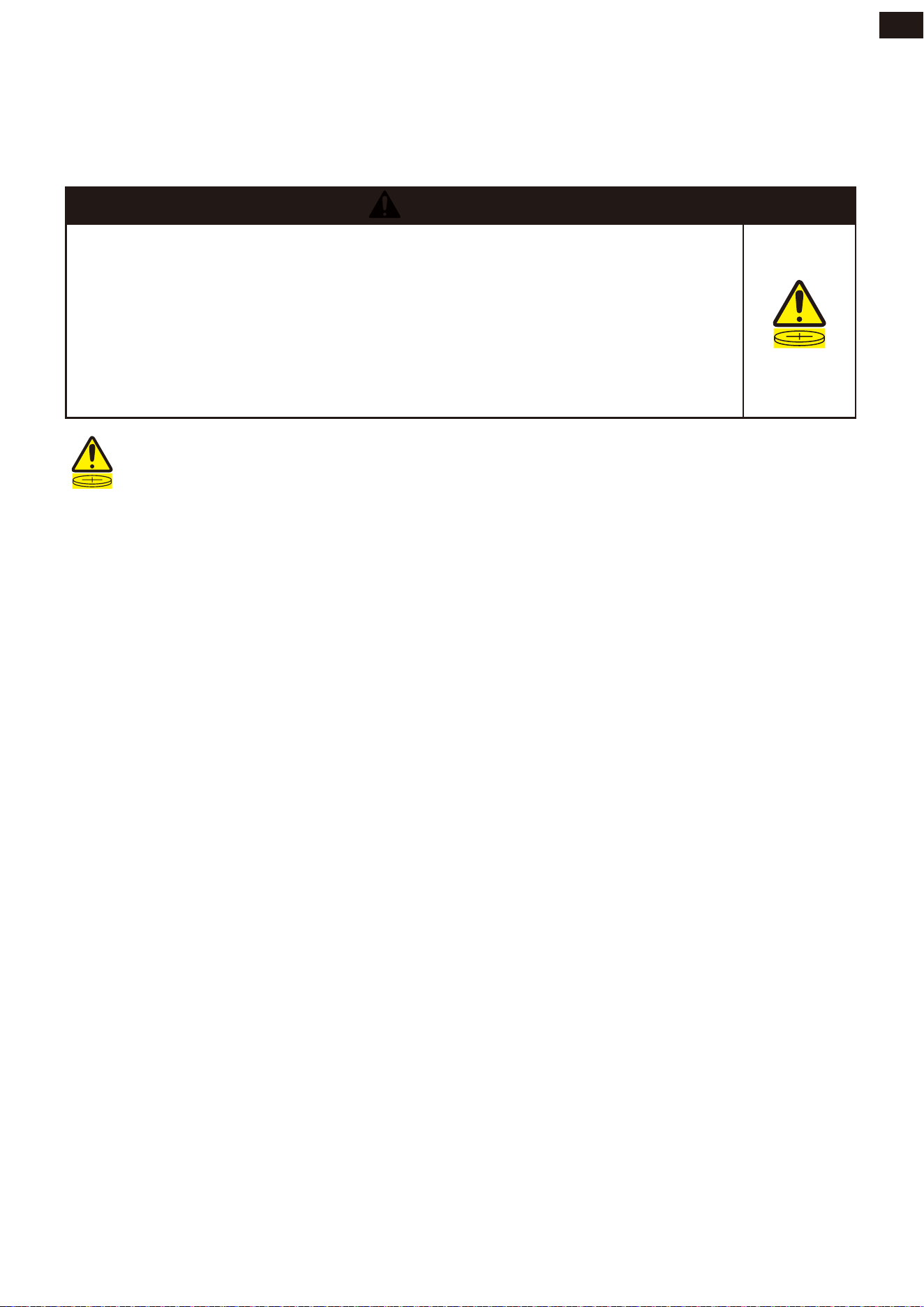
Button/Coin Battery Safety
WARNING
This symbol means:
INGESTION HAZARD: This product contains a button cell or coin battery.
1. Remove and immediately recycle or dispose of used batteries according to local regula-
tions and keep away from children. Do NOT dispose of batteries in household trash or
incinerate.
2. Even used batteries may cause severe injury or death.
3. Call a local poison control center for treatment information.
4. Non-rechargeable batteries are not to be recharged.
5. Do not force discharge, recharge, disassemble, heat above 140° Fahrenheit or incinerate.
Doing so may result in injury due to venting, leakage or explosion resulting in chemical
burns.
6. Battery spec in CO sensor and Remote Control Fob: CR2032 / 3V.
•INGESTION HAZARD: This product contains a button cell or coin battery.
•DEATH or serious injury can occur if ingested.
•A swallowed button cell or coin battery can cause Internal Chemical
Burns in as little as 2 hours.
•KEEP new and used batteries OUT OF REACH OF CHILDREN
•Seek immediate medical attention if a battery is suspected to be
swallowed or inserted inside any part of the body.
8
EN
SAFETY
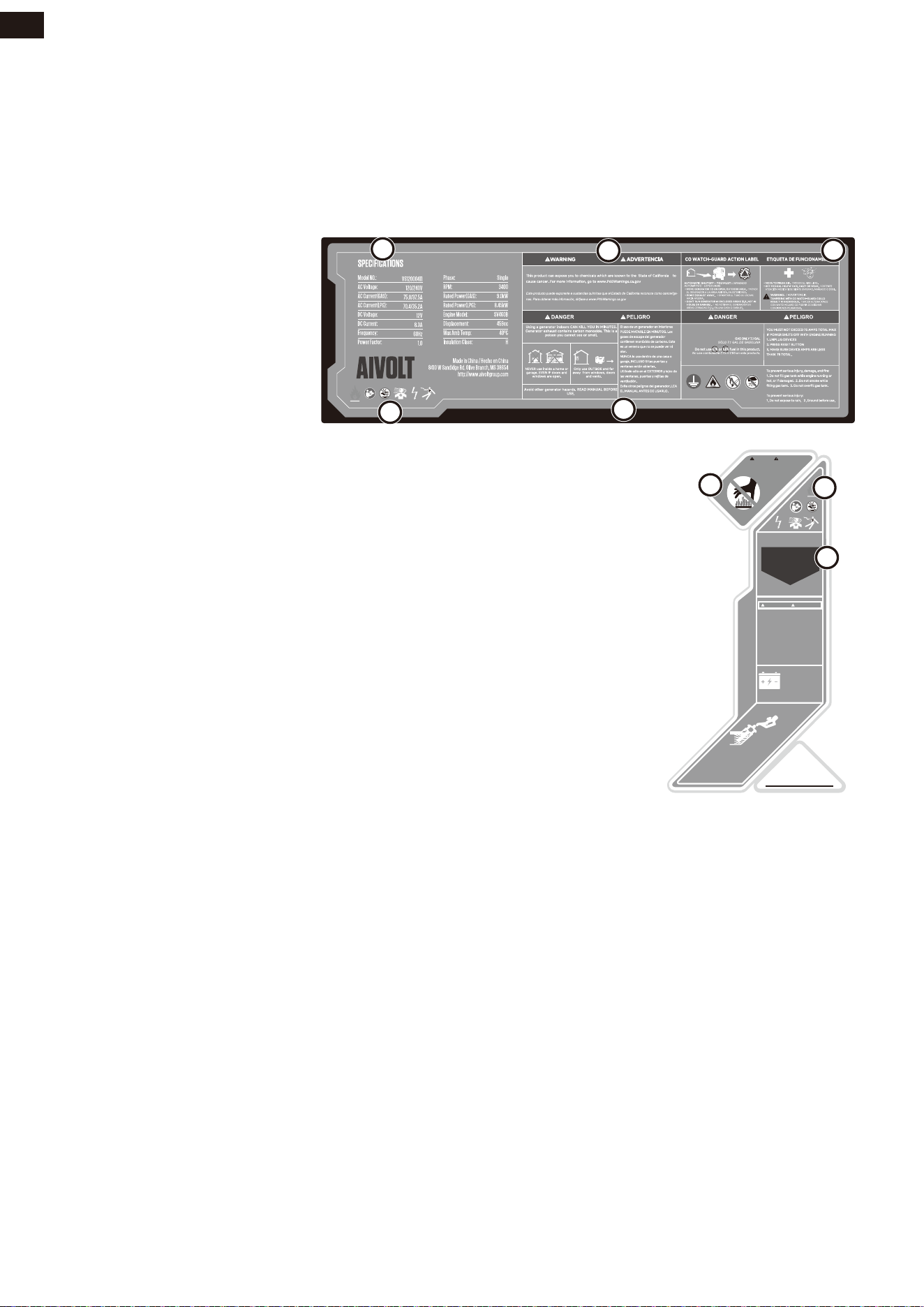
SAFETY LABELS AND DECALS
9
EN
The following information is on your genera-
tor’s labels and decals.
1. California Proposition 65
Cancer and reproductive
harm - www.P65Warnings.
ca.gov/product
2. Safety Symbols
3. Specifications
4. Action Label
If unsafe levels of carbon monoxide accumu-
late around the generator, automatic shutoff
will occur. If the unit shuts off, leave the area
immediately. When it is safe to return, do the
following:
• Move the generator to an open, outdoor
area.
• Point exhaust away.
• Don’t run generator in enclosed areas
(e.g. not in house or garage).
• Move to fresh air.
• Get medical help if sick, dizzy or weak.
• WARNING –Tampering with carbon mon-
oxide sensor could result in hazardous
condition.
5. Exhaust Direction
Point exhaust away from body parts and
flammable or combustible materials.
6. Hot Surface
Do not touch.
7. Carbon Monoxide
• Using a generator indoors CAN KILL YOU
IN MINUTES. Generator exhaust contains
carbon monoxide. This is a poison you
cannot see or smell.
• NEVER use inside a home or a garage,
AUTO
ENGINE
SHUTDOWN
APAGADO AUTOMÁTICO
DEL MOTOR
CO SafeGuard
POINT ORIENTAR
AWAY HACIA AFUERA
EXHAUST
EL TUBO DE ESCAPE
HOT SURFACE
SUPERFICIE CALIENTE
ADV ERTENC IAW ARNING
CAPACITY: 1.2L•1.27Qt•40.6Oz
BATTERY
COMPARTMENT
/COMPARTIMENTO
DE LA BATERÍA
CONNECT
BATTERY INSIDE
/CONECTE LA BATERÍA EN
EL INTERIOR
SAE 10W-30
Your unit has been shipped without
engine oil. Add oil prior to starting
or damage will occur. Engine will not
start or will shut off if low oil is
detected. / Su unidad ha sido enviada sin
aceite de motor. Agregue aceite antes de
arrancar o se producirán daños.El motor no
arrancará o se apagará si se detecta bajo nivel
de aceite.
Product does not include grounding
rod or copper wire. National Electric
Code requires generator to be
properly grounded to an approved
earth ground. Call an electrician for
local grounding requirements. / El
producto no incluye el alambre de cobre ni la
barra de conexión a tierra. Los reglamentos
Nacionales de Electricidad exigen que el
generador esté debidamente conectado a una
tierra aprobada. Comuniquese con un electrista
para todo lo relacionado con los requistos de
conexión a tierra.
ADVERTENCIAW ARNING
1
2
3
2
4
5
6
7
UNPACKING
WARNING
UNPACKING THE GENERATOR
Always have assistance when lifting
the generator. The generator is
heavy; lifting it could cause bodily
harm.
Avoid cutting on or near staples to
prevent personal injury.
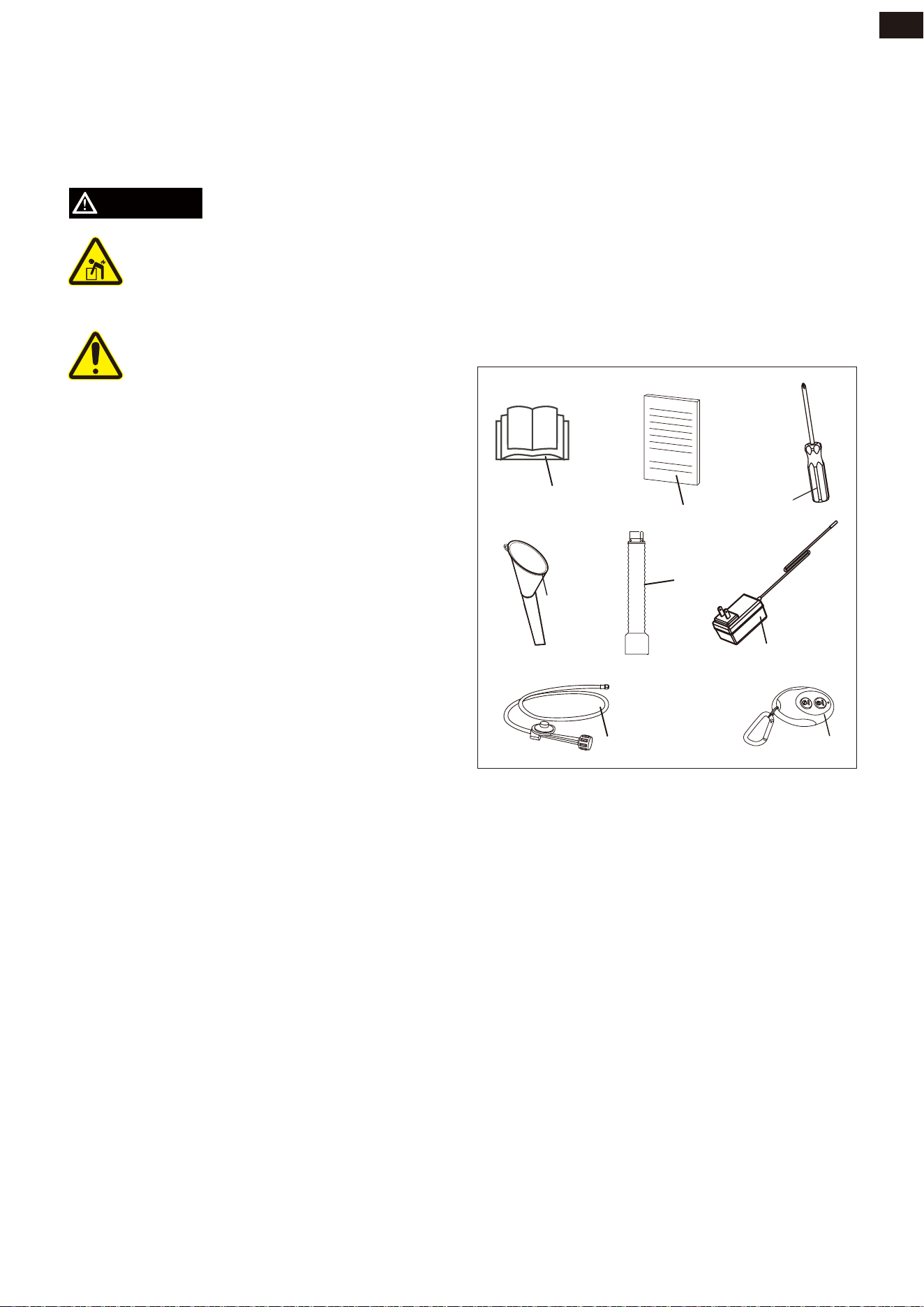
Parts Included
Your gasoline powered generator ships with
the following parts:
NO.
1
2
3
4
5
6
7
8
Item Description............................Qty.
Owner's Manual...................................1
Quick Start Guide................................1
Screw Driver.........................................1
Oil funnel...............................................1
Spark Plug Wrench.............................1
Charger.................................................1
LPG Hose with Regulator...................1
Remote Control Fob............................1
• Open carton completly. Remove and
verify carton content prior to assembly.
Your generator shipswith following
items.
• Record model, serial number, and date of
purchase on front cover of this munual
for your own record.
10
EN
1
2
3
5
7
4
6
8
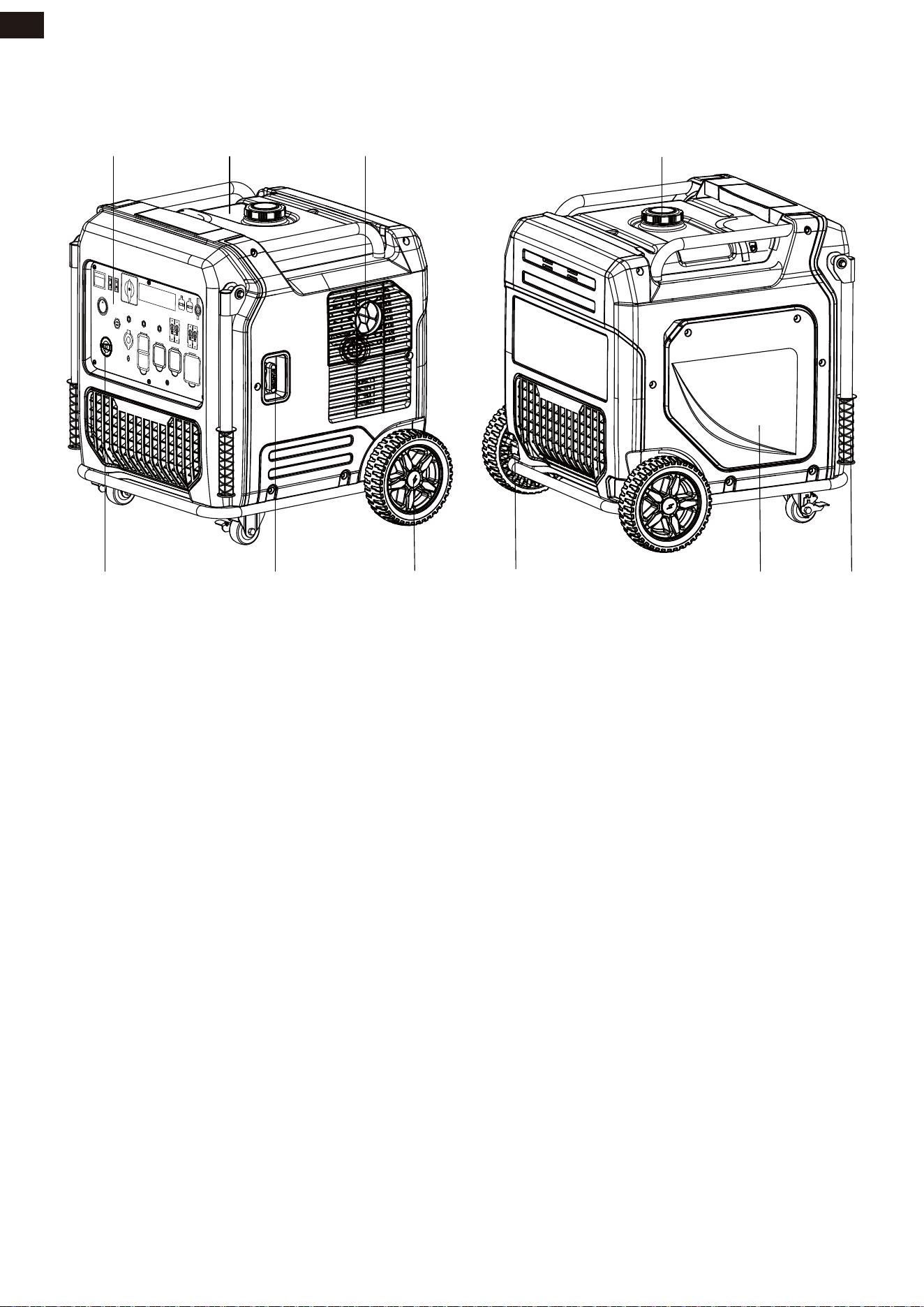
CONTROLS AND FEATURES
11
EN
1
1
9
4
3
10
2
7
5
6
8
1 - Control Panel
2 - Fuel Tank
3 - Muffler
4 - Fuel Cap
5 - Handle
6 - Maintenance Cover
7 - Wheel Lock
8 - Wheel
9 - Recoil Handle
10 - Fuel Switch
ENGINE
START
STOP
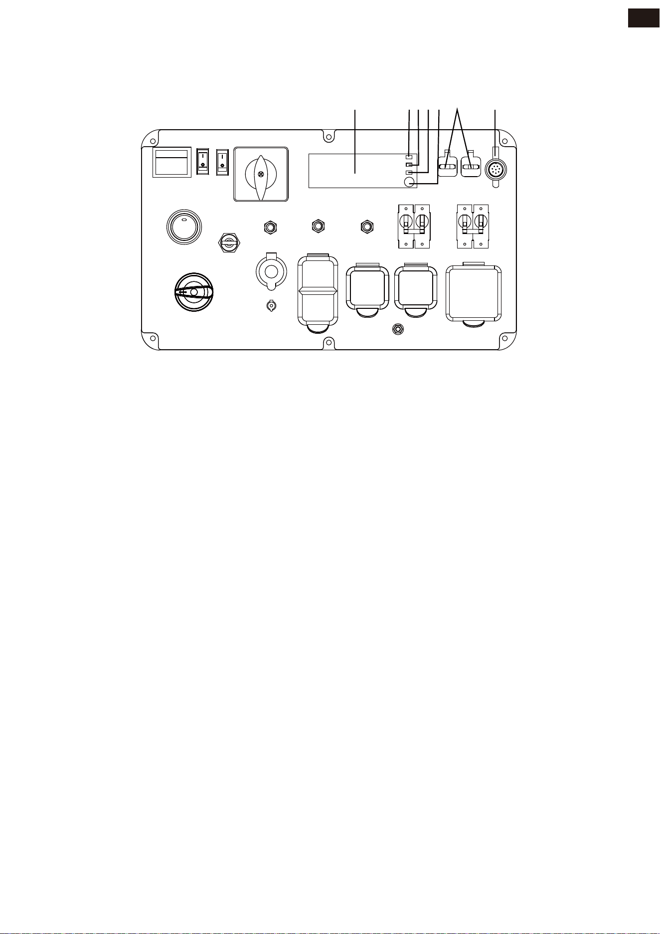
CONTROL PANEL FEATURES
NOTE: Total power drawn from all outlets must not exceed the nameplate rating.
12
EN
1. LCD Multi-Meter: Displays voltage,
frequency, fuel remaining, power output,
single running time, and total running
time.
2. Output Ready Indicator LED (Green):
Illuminates when the generator is operat-
ing normally and indicates the generator
is producing electrical power at the
receptacles.
3. Overload Indicator LED (Red): Illuminates
when the generator is overloaded which
means the generator’s wattage / amper-
age capacity has been exceeded by con-
nected electrical devices or by a power
surge. When this occurs, the Output
Ready Indicator LED will go off. The
engine will continue to run, but the red
Overload Indicator LED will stay on, and
power will no longer be supplied to con-
nected electrical devices. To rest the
generator: Remove all applied loads and
stop the engine. Review for any faulty or
shorted connections. Start the generator
and reconnect electrical devices
sequentially, allowing the generator to
stabilize after each device is connected.
Make sure the total wattage of connect-
ed electric devices are not exceeding
recommended rated output power.
4. Oil Warning Indicator LED (Red): Illumi-
nates when the engine oil level falls
below the safe operating level and the
generator will automatically shut off the
engine. The engine will not start until the
proper amount of oil is in the crankcase.
5. CO (Carbon Monoxide) WATCH-GUARD
Indicator Light (Red for Shut off and
Yellow for Service): The CO (Carbon
Monoxide) WATCH-GUARD monitors for
the accumulation of poisonous CO gas
around the generator produced by
engine exhaust when the generator is
running. If the CO WATCH-GUARD
detects increasing levels of CO gas, it
automatically shuts off the engine. See
CO WATCH-GUARD section for more
information.
6. Parallel Operation Outlets: These outlets
are used or connecting two AIVOLT
inverter generators for parallel operation.
Do not connect or disconnect parallel
cables while the generator is running to
avoid damage.
7. ATS Plug: Allows use with automatic
transfer switches.
2 5 6 743
1
ENGINE
START
STOP
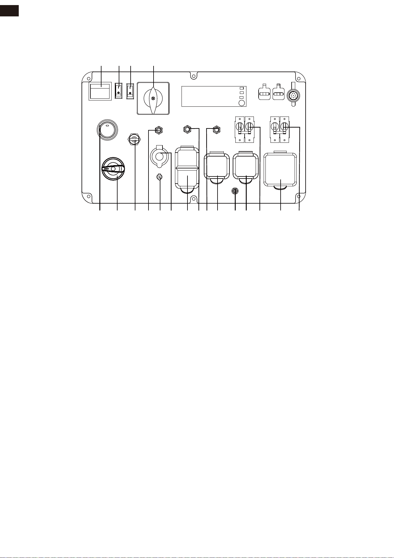
CONTROL PANEL FEATURES
13
EN
1. Start Up Switch: Allows power to the
starter and panel. Prevents accidental
starting.
2. Fuel Switch: GAS/LPG valve that changes
the fuel into the engine.
3. Low Idle Switch: Low idle switch mini-
mizes fuel consumption and noise by
adjusting the engine speed to the mini-
mum required for the current load.
4. Voltage Selector Switch: To select 120
Volt or 240 Volt. Turn generator off
before switching voltages.
5. Circuit Breaker: Protects the generator
against electrical overloads.
6. 120/240V AC, 50A, Single Phase, 60 Hz
Outlet (NEMA 14-50R): This outlet can
supply 120 Volt output up to 50amps and
240 Volt output up to 50 amps.
7. 120/240V AC, 30A Twist Lock, Single
Phase, 60 Hz Outlet (NEMA L14-30R):
supply either 120 Volt or 240 Volt output
up to 30 amps.
8. Ground Terminal: The ground terminal is
used to ground the generator.
9. 120V AC, 30A Twist Lock outlet, single
phase, 60Hz Outlet (NEMA L5-30R): This
outlet can provide 120 volt output up to
30 amps.
10.Circuit Breaker(AC): Protects the genera-
tor against electrical overloads.
11.120V AC, 20A Duplex, GFCI, Single Phase,
60 Hz Outlets (5-20R): Each outlet is
capable of carrying a maximum of 20
amps on a single outlet or a combination
of both outlets.
12.12V DC, Outlet (Automotive): Provides 12
volt DC power up to 8.3 amps.
13.Battery Charging Port: Use to charge the
battery.
14.Circuit Breaker(DC): Protects the genera-
tor against electrical overloads.
15.LPG Inlet: Connects the LPG inlet to the
LPG hose/regulator.
16.Fuel Valve: On/Off valve that allows gas-
oline into the engine.
17.Push-Button START/STOP: Push once to
automatically start the engine. Push
again to stop the engine. Press the button
5 times within 3 seconds until it turns red
to match the remote control keys.
1
71216 81117 101315 910 6 55
2 3 4
14
ENGINE
START
STOP

NOTICE
SPECIFICATIONS
Generator Specifications
This product is designed and rated for continuous operation at ambient temperatures up to
104°F(40°C). If needed, this product can be operated at temperatures ranging from 5°F(-15°C)
- 122°F(50°C) for short periods. If the product is exposed to temperatures outside of this range
during storage, it should be brought back within this range before operation. This product
must always be operated outdoors in a well-ventilated area and far away from doors,
windows, and other vents.
Maximum wattage and current are subject to and limited by such factors as fuel BTU content,
ambient temperature, altitude, engine conditions, etc. Maximum power decreases about 3.5%
for each 1,000 feet above sea level, and will also decrease about 1% for each 10°F(6°C) above
60°F( 16°C) ambient temperature.
Model
Starting Watts
Running Watts
Rated AC Voltage
Rated DC Voltage
Rated Frequency
Phase
Grounding System (AC)
Engine Type
Engine Displacement
Starting System
Low Oil Shutdown
Oil Type
Oil Capacity
Spark Plug OEM Type
Voltage Regulation System
Alternator Excitement System
Total Harmonic Distortion (THD)
Fuel Tank Capacity
Fuel Type
Maximun Ambient Temperature
Battery Spec
Certifications
VS12000411
11250W-GAS / 10570W-LPG
9000W-GAS / 8450W-LPG
120V / 240V
12V
60Hz
Single
Neutral Bonded to Frame
Single Cylinder, 4-Stroke OHV Air Cooled
459cc
Recoil – Electric - Remote
Yes
10W-30
40.6 fl.oz (1.2 L)
NGK BPR6ES
Digital Inverter
Permanent Magnet
<3%
7.1 gallon (27.00 L)
Gasoline / LPG
104°F (40°C)
12V, 10Ah
EPA-CARB-PGMA Compliant
14
EN
CO WATCH-GUARD
Carbon Monoxide (CO) Detection and Auto Shutoff System
NOTIFICATIONS: BLINKING RED AND YELLOW LIHGT
Your Generator is equipped with Carbon Monoxide (CO) WATCH-GUARD detect system for
your protection and safety. This detecting and shutoff system monitors for the accumulation
of poisonous CO gas around the generator produced by engine exhaust when the generator
is running. If the CO sensor detects increasing levels of CO gas, it automatically shuts off the
engine.
Generators are intended to be used outdoors and far away from occupied buildings, windows,
doors and exhaust pointed away from them.
EXHAUST[CO]
KEEP
FAR AWAY
CO Detector
in Living Areas
Direct exhaust
AWAY from
windows, doors,
Only use OUTSlDE and
FAR AWAY from windows,
doors and vents.
However, if the generator misused and operated in a location that results in the accumulation
of CO inside an enclosed or partially enclosed space, CO WATCH- GUARD automatically
shuts off the engine and notifies the user of what has happened and directs the user to read
the instruction of CO WATCH-GUARD Action Label for steps to take.
AUTOMATIC SHUTOFF - YOU MUST:
• MOVE GENERATOR TO AN OPEN, OUTDOOR AREA.
• POINT EXHAUST AWAY.
• DON’T RUN GENERATOR IN ENCLOSED AREAS
(E.G. NOT IN HOUSE OR GARAGE).
APAGADO AUTOMÁTICO - USTED DEBE:
• MOVER EL GENERADOR A UN ÁREA ABIERTA, EN
EXTERIORES.
• ORIENTAR EL TUBO DE ESCAPE HACIA AFUERA.
• NO ACTIVAR EL GENERADOR EN ÁREAS CERRADAS
(P.EJ.: EN UNA CASA O GARAJE).
• MOVE TO FRESH AIR.
• GET MEDICAL HELP IF SICK, DIZZY OR WEAK.
• MOVER AL AIRE LIBRE.
• OBTENER ATENCIÓN MÉDICA SI SE SIENTE ENFERMO,
MAREADO O DÉBIL.
WARNING: / ADVERTENCIA:
TAMPERING WITH CO WATCH-GUARD COULD
RESULT IN HAZARDOUS
/ HACER ALTERACIONES CON WATCH-GUARD
CO PODRíA OCASIONAR CONDICIONES PELIGROSAS.
CO WATCH-GUARD ACTION LABEL / ETIQUETA DE FUNCIONAMIENTO
There is a CO indicator light on the control panel with two possibilities:
1-Blinking Red Light provides notification that the generator was shutoff due to an
accumulating CO level around the generator. The red light will blink for at least five minutes
after a CO shut off. Automatic shutoff is an indication generator was improperly located. Move
the generator to an open, outdoor area far from occupied
spaces with exhaust pointed away. Once relocated to a safe area, the generator can
berestarted. The red light will stop blinking automatically after 2-5 seconds upon engine
re-start.If you start to feel sick, dizzy, weak, or your homes carbon monoxide alarm sounds
while using the generator, get to fresh air right away. Call emergency services. You may have
carbon monoxide poisoning.
15
EN
CO WATCH-GUARD
2-Blinking Yellow Light provides notification that a CO WATCH-GUARD fault has occurred
and no longer provides protection. The generator is shutoff automatically and the yellow light
will blink for at least five minutes after shutoff. Email AIVOLT Customer Service
[email protected] for repair. Do not use the generator until the sensor is work-
ing properly. The CO WATCH-GUARD must only be serviced by qualified technician to restore
it to original settings.
16
EN
WARNING
WARNING
DO NOT modify or tamper with the Carbon Monoxide Detecting System (CO
WATCH-GUARD). Not following these instructions could result in death or serious injury due
to Carbon Monoxide detecting system malfunction.
CO WATCH-GUARD will detect the accumulation of carbon monoxide from other fuel burning
sources such as engine powered tools used in the area of operation. If another generator is
used and the exhaust is pointed at a CO WATCH-GUARD equipped generator, the CO
WATCH-GUARD may initiate a shutoff due to rising carbonmonoxide levels. This is not a fault.
Hazardous carbon monoxide has been detected. You must take action to
move and direct the equipment to better dissipate carbon monoxide far away from people or
buildings.
CO WATCH-GUARD only monitors when the generator is running.
CO WATCH-GUARD DOES NOT replace carbon monoxide alarms.
Tempering with the CO WATCH-GUARD will void your warranty.
Tampering with CO WATCH-GUARD could result in a hazardous condition. Removing the CO
WATCH-GUARD module will not allow the generator to start.
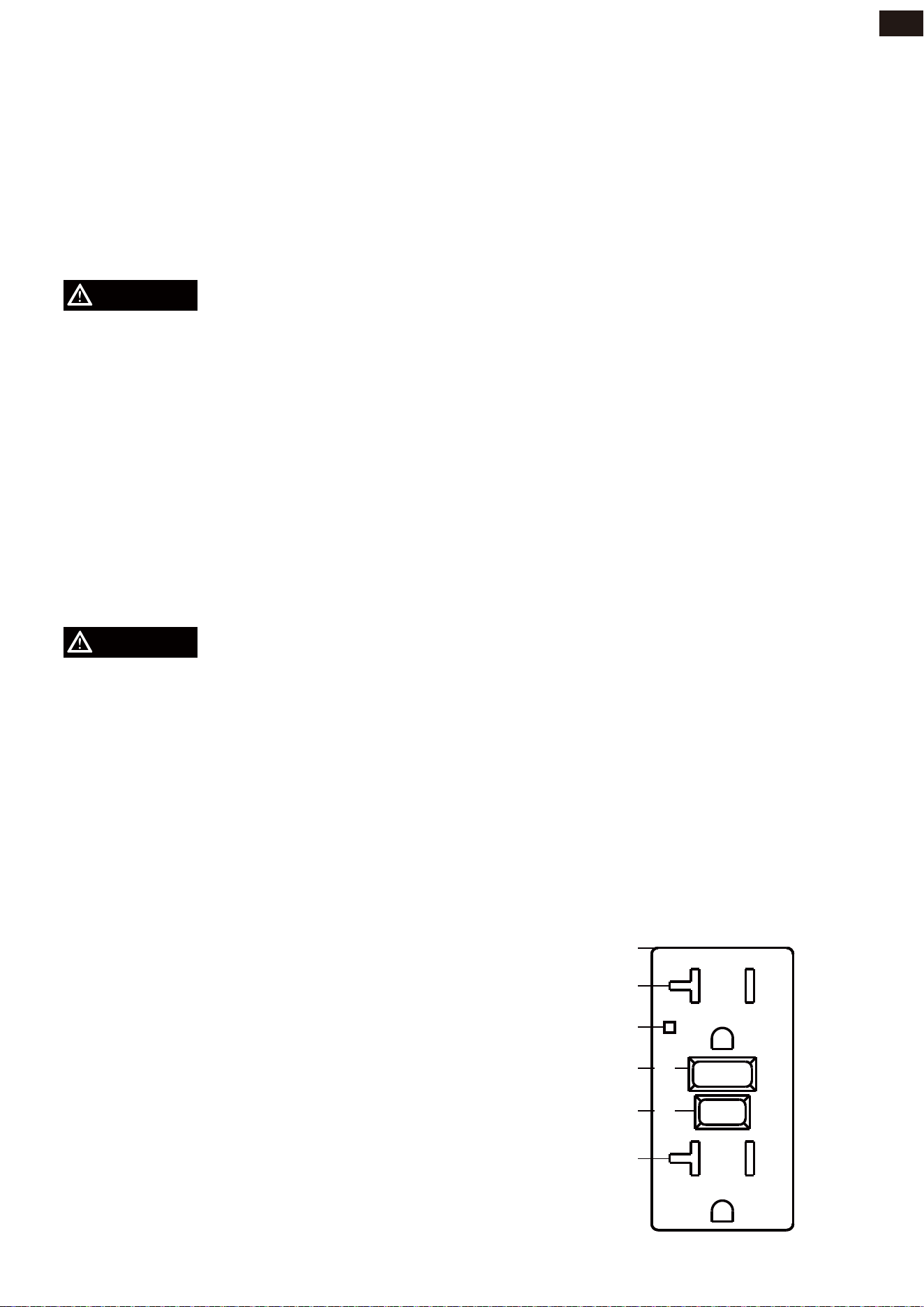
120V AC, 20A Duplex GFCI
Your generator is equipped with ground fault circuit interrupter (GFCI) receptacles. In the
event of a ground fault,a GFCI trips automatically to stop the flow of electricity and prevent
serious injury. The LED Indicator Light onthe receptacle will be turn off. Press the “RESET”
button located on the front of the receptacle to restore flow ofelectricity. GFCI does NOT pro-
tect against circuit overloads. To ensure proper operation of the GFCI duplex,perform this test
monthly:
Receptacle
LED Indicator Light
Outlet
Reset Button
Test Button
Outlet
RESET
TEST
FOLLOW DIRECTIONS
1. With the generator running, plug a test
lamp into the GFCI receptacle. Turn the
lamp on.
2. Press the “TEST” button located on the
front of the receptacle to trip the device.
This should immediately stop the flow of
electricity and shut off the lamp. If the
electricity is not stopped, do not use this
receptacle until it has been serviced or
replaced.
3. Press the “RESET” button located on the
front of the receptacle to restore the flow
of electricity. If the LED Indicator Light
does not come back or GFCI cannot be
reset, then it must be replaced.
TEST MONTHLY
OPERATION
Add Engine Oil
We recommend using SAE 10W-30 APISJ oil
for best performance. Other high-quality
detergent oils (APISJ or higher) are accept-
able. Do not use special additives. Ambient
temperature determines the proper oil
viscosity for the engine. Use the chart to
select the proper oil for the outdoor tem-
perature range expected.
Do not attempt to crank or start the engine
before it has been properly filled with the
recommended type and amount of oil.
Damage due to operation with no oil will void
your warranty.
1. Place generator on a flat and level sur-
face.
2. Unscrew and remove the engine service
cover to access the oil dipstick.
3. Remove oil dipstick.
4. Using the 4-cycle engine oil and funnel,
slowly add engine oil to the engine until
full.
5. Do not overfill. If oil level is too high, oil
will drain out through the fill plug.
6. Reinstall oil fill cap dipstick and fully
tighten.
7. Oil level should be checked prior to each
use or at least 8 hours of operation. Keep
oil level maintained.
-20 0 20 40 60
Ambient temperature
Recommended Engine Oil Type
80 100 120
-28.9
°F
°C
-17.8 -6.7 4.4 15.6 26.7 37.8 48.9
10W-30
5W-30 Full Synthetic
10W-405W-30
NOTICE
NOTICE
The engine is equipped with a low oil
shut-off and will stop when the oil level in
the crankcase falls below the threshold level.
We consider the first 5 hours of run time to
be the break-in period for the unit. During
the break in period stay at or below 50% of
the running watt rating and vary the load
occasionally to allow stator windings to heat
and cool. Adjusting the load will also cause
engine speed to vary and help seat piston
rings.
17
EN
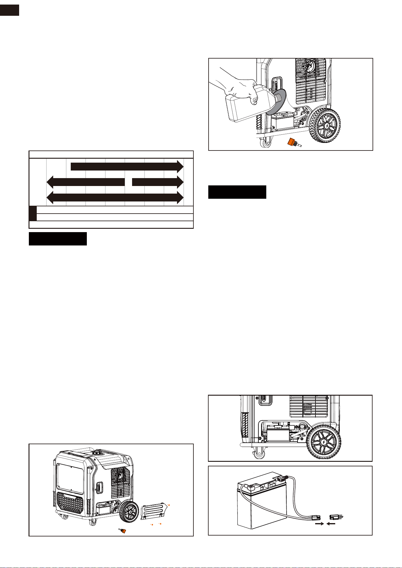
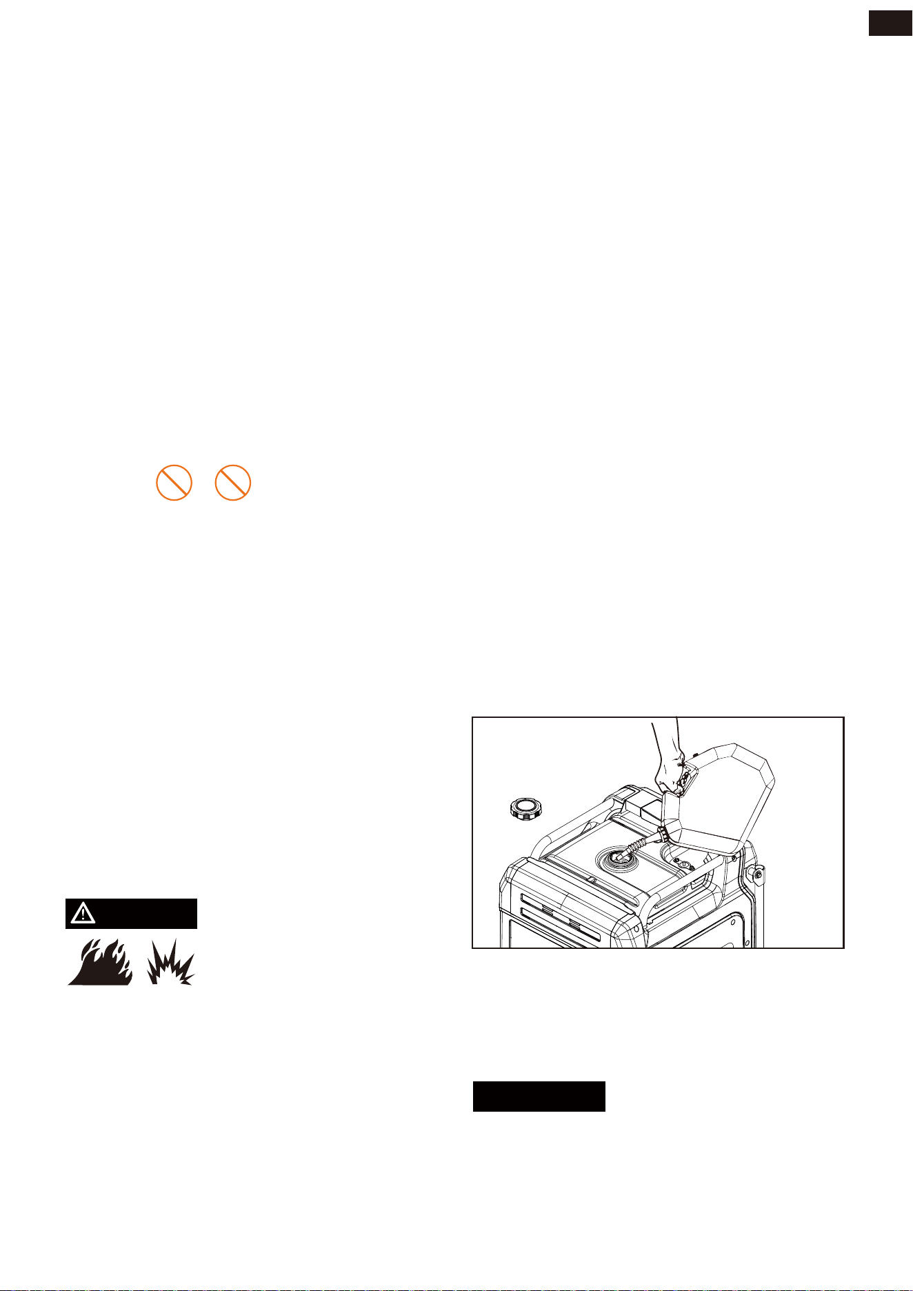
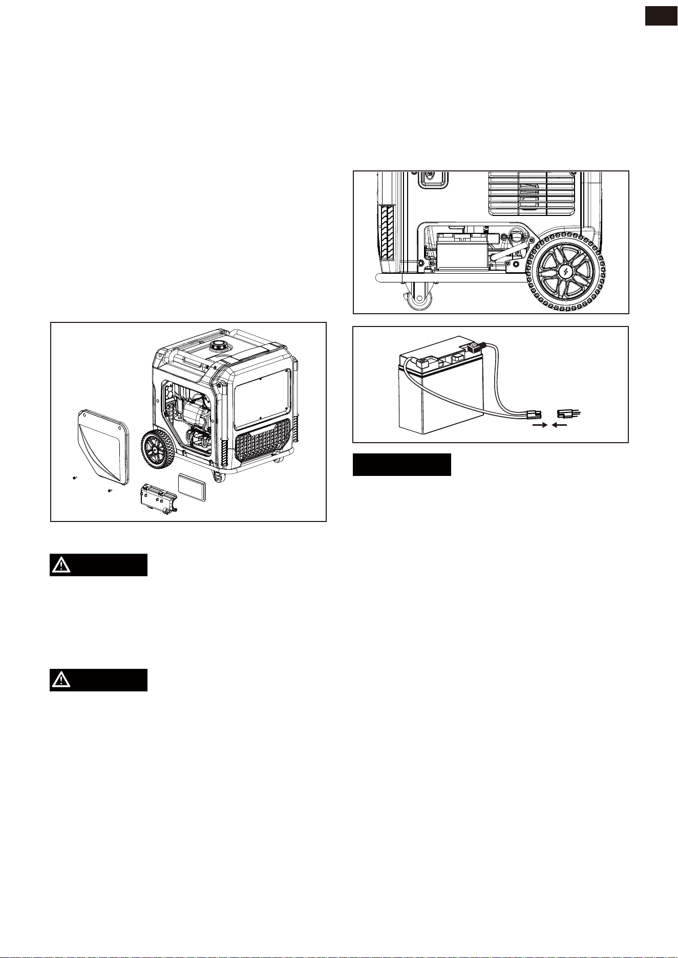
Battery Cable Connection
1. loosen maintenance cover knobs to be
able to remove the cover.
2. A quick connect battery plug is pre-in-
stalled on the battery.Cut the cable tie
securing the plugs and push two halves A
and B firmly to connect them.
3. Reinstall and secure the maintenance
cover.
To connect the Battery
OPERATION
18
EN
Low Oil Shutdown
Add Fuel: Gasoline
The unit is equipped with a low oil shutdown.
If the oil level becomes lower than required,
the sensor will activate a warning device or
stop the engine.If generator shuts off and
the oil level is within specifications, check
to see if generator is sitting at an angle that
forces oil to shift. Place on an even surface
to correct this. If engine fails to start, the oil
level may not be sufficient to deactivate low
oil level switch. Make sure the sump is
completely full of oil.
Do not use E15 or E85 fuel in this product.
• Engine or equipment damage caused by
stale fuel or the use of unapproved fuels
(such as E15 or E85 ethanol blends) is not
covered by warranty.
• Only use unleaded gasoline containing
up to 10% ethanol.
• ALWAYS use CLEAN, FRESH, unleaded
gasoline (87–93 octane) in this unit.
• NEVER use OLD, STALE, or CONTAMI-
NATED gasoline.
• Up to 10% ethanol (gasohol) is acceptable
(where available; non-ethanol fuel is rec-
ommended).
• DO NOT use E85 or E15.
• DO NOT use a gas oil mix.
• DO NOT modify the engine to run on
alternate fuels.
DANGER
• Fuel and its vapor are extremely flamma-
ble and explosive. Add fuel in a well ven-
tilated area. Keep sparks, open flames
and other ignition sources away. Failure
to do so will result in death and serious
injury.
• Do not overfill tank. Allow space for fuel
expansion. If fuel spills wait until it evapo-
rates before starting engine. Failure to do
so will result in death and serious injury.
Fuel must meet these requirements:
• Clean, fresh, unleaded gasoline.
• Use regular UNLEADED gasoline with the
generator engine with a minimum 87
octane / 87 AKI (91 RON). Do not use E85
or E15.For high altitude use, see "Opera-
tion at High Altitude".
• DO NOT mix oil in gasoline.
• DO NOT modify engine to run on alter-
nate fuels.
WHEN ADDING FUEL
• Fill fuel tank outdoors.
• DO NOT overfill tank. Allow space for fuel
expansion.
• If the tank is overfilled, fuel can overflow
onto a hot engine and cause fire or explo-
sion.If fuel spills, wait until it evaporates
before starting engine.
• Keep fuel away from sparks, open flames,
pilot lights, heat, and other ignition
sources.
• Check fuel lines, tank, cap and fittings
frequently for cracks or leaks. Replace if
necessary.
• DO NOT light a cigarette or smoke when
filling the fuel tank.
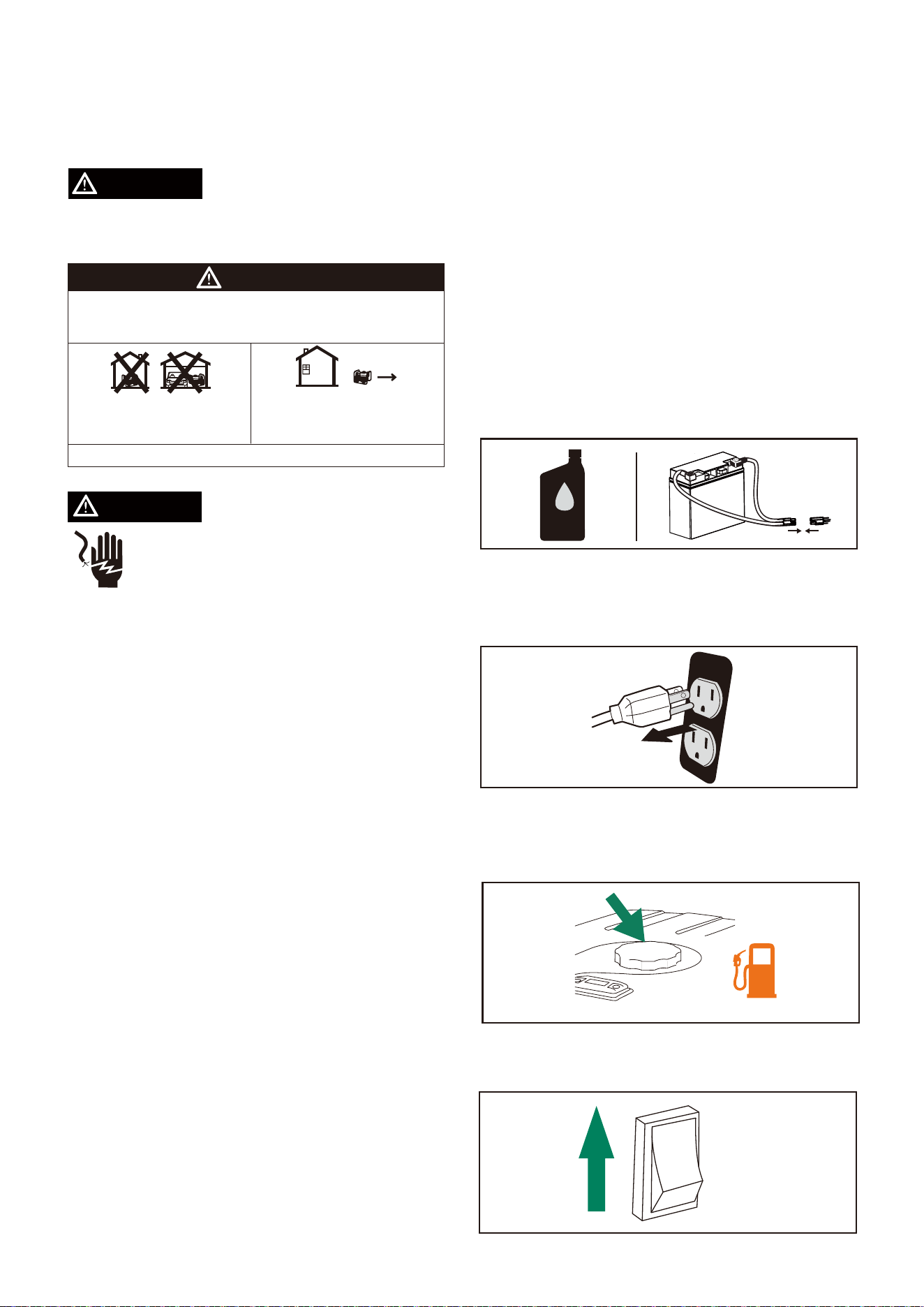
1. Unscrew gas cap on top of tank.
2. Slowly add gasoline into the fuel tank.
The gasoline level should NOT be higher
than the red maximum fillring.
3. Secure gas cap.
NOTICE
• Gasoline can damage paint and plastic.
Use caution when filling the fuel tank.
Damage caused by spilled gasoline is not
covered under warranty.
OPERATION
19
EN
• It is important to prevent gum deposits
from forming in fuel system parts such as
the carburetor, fuel hose or tank during
storage. Alcohol-blended fuels (called
gasohol, ethanol or methanol) can attract
moisture, which leads to separation and
formation of acids during storage. Acidic
gas can damage the fuel system of an
engine while in storage. To avoid engine
problems, the fuel system should be
emptied before storage of 30 days or
longer. See the "Long Term Storage" sec-
tion. Never use engine or carburetor
cleaner products in the fuel tank as per-
manent damage may occur.
• Only fill the tank from an approved gaso-
line container. Make sure the gasoline
container is internally clean and in good
condition to prevent fuel system contam -
ination.
• Clean the fuel screen filter of debris
before and after each fueling. Remove
the fuel screen filter by slightly com-
pressing it while removing it from the
fuel tank.
Add Fuel: LPG
DANGER
• The provided LPG hose with regula-
tor,works with standard 20, 30 and 40
pound capacity cylinders with Type 1,
right hand Acme threads. Verify the
re-qualification date on the tank has not
expired. Do not use rusted or damaged
cylinders.
• Only use provided LPG hose for safe LPG
operation.
NOTICE
12V
OFF OFF OFF OFF
45"35
4501
&/(*/&
• Use only an approved LPG cylinder
equipped with an OPD (overfilling pre-
vention device) valve.
• DO NOT check for leaks with a lighted
match or flame.
• The propane cylinder valve should be
fully closed when the generator is not in
use or is running with gasoline.
• The regulator/hose assembly and cylin-
der valve must be inspected before each
use for leaks or sign of damages.
• All new cylinders must be purged of air
and moisture prior to filling. Used cylin-
ders that have not been plugged or kept
closed must also be purged.
• LPG is heavier than air and can accumu-
late in confined spaces and low places in
the event of a leak
1. Make certain both gasoline and LPG
valves are closed.
2. Remove the rubber protective plugs (if it
is available) and attach the LPG hose
with regulator to the LPG inlet located on
the side control panel of the generator.
Tighten with a 19mm or adjustable
wrench. DO NOT over-tighten.
3. Remove safety plug from the LPG cylin-
der valve (if it is available) and attach the
other end of the LPG hose with regulator
to cylinder valve. Tighten the nut by
hand clockwise to a positive stop.
4. Open valve on LPG cylinder and check all
connections for leaks by wetting the
fittings with a solution of soap and water.
Bubbles which appear or bubbles which
grow indicate that a leak exists. If a leak
exists at a fitting, then turn off the valve
on the cylinder and tighten the fitting.
Turn the valve back on and recheck the
fitting with the soap and water solution.
If the leak continues or if the leak is not
at a fitting, then do not use the generator
and contact customer service.
LPG is highly flammable
and explosive. Fire or
explosion can cause severe
burns or death.
IMPORTANT: DO NOT use thread seal tape
or any type of sealant to seal the LPG hose
connections.
OPERATION
20
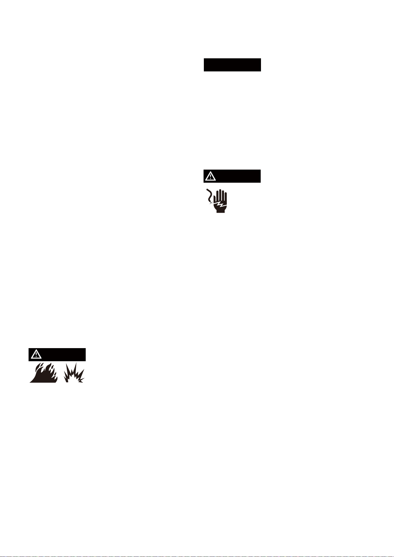
Shock hazard. Failure to properly
ground the generator can result in
electric shock.
WARNING
Grounding
NOTICE
Operation at High Altitude
At altitudes over 5,000 feet(1524 meters), a
minimum 85 octane gasoline is acceptable.
Engine power and generator output will be
reduced approximately 3.5% for every 1000
feet (305 m) of elevation above sea level.
High altitude may cause hard starting,
increased fuel consumption and spark plug
fouling.
Operation using an alternative main jet at
elevations lower than the recommended
minimum altitude can damage the engine.
For operation at lower elevations,the stan-
dard main jet supplied must be used. Oper-
ating the engine with the wrong main jet
may increase exhaust emissions, fuel con-
sumption and reduce performance.
The national electrical requires your genera-
tor must be connected properly to an appro-
priate ground to help prevent electric shock.
The generator has a system ground that
connects the generator frame components
to the ground terminals on the AC output
receptacles. There may be Federal or State
regulations, local codes, or ordinances that
apply to the intended use of the generator.
Consult a qualified electrician, electrical
inspector, or the local agency having juris-
diction. This generator is not intended to be
used at a construction site or similar activity
as defined by NFPA 70-2020 (NEC) section
590.6.
Connecting to a Building's Electrical
System
Connections to your home’s electrical
system must use a listed transfer switch
installed by a licensed electrician. The con-
nection must isolate the generator power
from the utility power and comply with all
applicable laws and electrical codes.
DANGER
• LPG has a distinctive odor added to help
detect potential leaks quickly.
• In case of a petroleum gas fire, do not
attempt to extinguish the flame if the fuel
supply valve is in the ON position. Intro-
ducing an extinguisher to a generator
with an open fuel supply valve could
create an explosion hazard.
• When exchanging LPG cylinders, be sure
the cylinder valve is of the same type.
• Always keep the LPG cylinder in an
upright position.
• LPG will burn skin if it comes in contact
with it. Keep LPG away from skin at all
times.
• Always position the cylinder so the con-
nection between the valve and the regu-
lator won’t cause bends or kinks in the
hose.
• DO NOT light or smoke cigarettes while
you are connecting the LPG cylinder. -
Check the fuel system periodically for
leaks or signs of damage.
• In the event of an LPG fire, flames should
not be extinguished unless by doing so
the fuel supply valve can be turned off. If
the fire is extinguished and a supply of
fuel is not turned off, an explosion hazard
greater than the fire hazard could be cre-
ated.
Do not start generator if
you smell propane. ls fully
close the propane tank valve and disconnect
the LPG hose from the generator when not
in use.
OPERATION
21
DANGER
Never use generator in wet or damp
locations. Never expose generator to
rain, snow, water spray or standing
water while in use.
WARNING
Generator Location
Surge Protection
Before Starting the Generator
Make sure you review each warning in order
to prevent fire hazard.
Protect generator from all hazardous weath-
er conditions. Moisture, or ice can cause a
short circuit or other malfunction in the elec-
tric circuit. Water contact with a power
source if not avoided, will result in death or
serious injury.
Avoid other generator hazards. READ MANUAL BEFORE USE.
DANGER
Using a generator indoors CAN KILL YOU IN MINUTES.
Generator exhaust contains carbon monoxide. This is a poison
you cannot see or smell.
Only use OUTSIDE and
far away from windows,
doors and vents.
NEVER use inside a home
or garage, EVEN IF doors
and windows are open.
• Keep area clear of inflammables or other
hazardous materials.
• Select a site that is dry, well ventilated
and protected from the weather.
• Keep exhaust pipe clear of foreign
objects.
• Keep generator away from open flame.
• Keep generator on a stable and level sur-
face.
• Do not block generator air vents with
paper or other material.
Electronic devices, including computers and
many programmable appliances use com-
ponents that are designed to operate within
a narrow voltage range and may be affected
by momentary voltage fluctuations. While
there is no way to prevent voltage fluctua -
tions, you can take steps to protect sensitive
electronic equipment.
Install UL1449, CSA-listed, plug-in surge
suppressors on the outlets feeding your sen-
sitive equipment. Surge suppressors come
in single- or multi-outlet styles. They’re
designed to protect against virtually all
short-duration voltage fluctuations.
• Before starting the generator, check for
loose or missing parts and for any
damage which may have occurred during
shipment.
• Check oil level and connect the battery
cable.
• Disconnect all electrical loads from the
generator. Never start or stop the gener-
ator with electrical devices plugged in or
turned on.
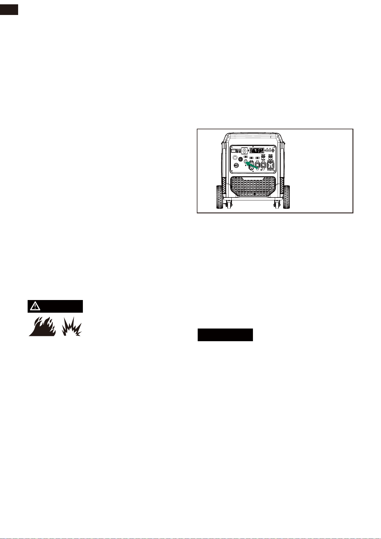
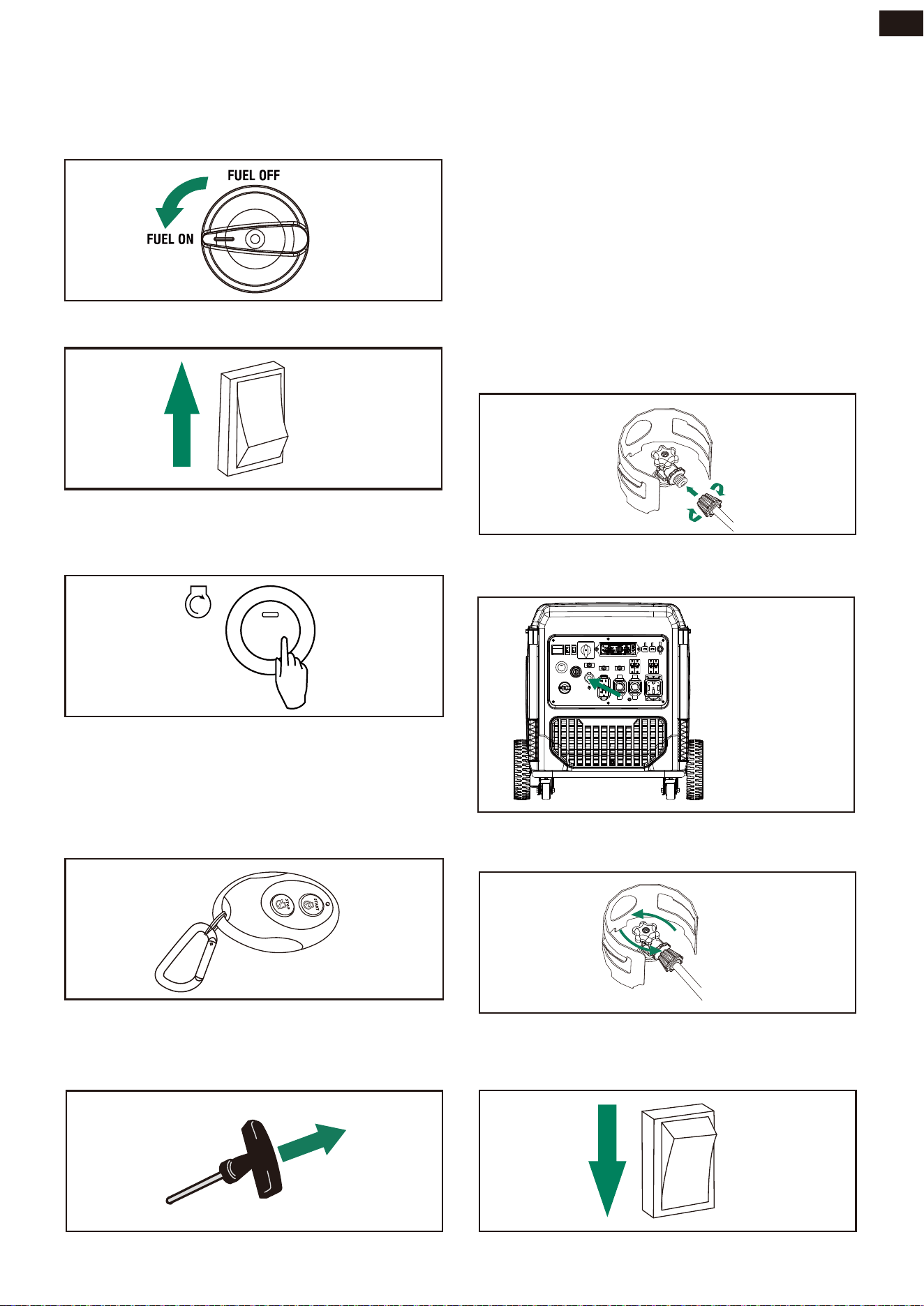
Starting the Engine (Generator)
Select the Fuel Source (Gasoline)
1. Add gasoline to the fuel tank
2. Flip the fuel source switch on the side
panel to the gasoline position.
GAS
LPG
OPERATION
22
EN
12V
OFF OFF OFF OFF
45"35
4501
&/(*/&
Select the Fuel Source (LPG)
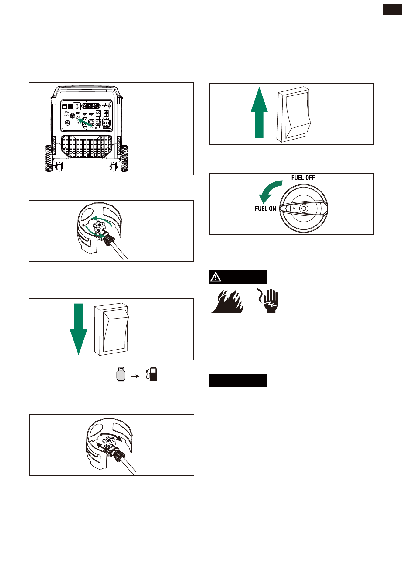
4. Turn the fuel source switch to the LPG
position.
3. Turn the Fuel Switch to the“ON” position.
4. Turn the Engine Switch to “ON” position.
5c. Recoil Start
Pull the starter cord slowly until resistance is
felt and then pull rapidly.
5b. Remote Start
5a. Electric Start
START
STOP
ENGINE
Turn and hold the ENGINE START/STOP
switc for 3-5 seconds until the engine start.h
Turn and hold the REMOTE START switch
for 3 seconds until the engine start. 164-feet
(50 meters) long-distance control, meeting
the FCC requirements.
NOTE: After turning off the generator for 18
hours, the generator needs to be restarted
by the electric start switch before using the
remote start.
1. Connect the LPG gas hose to the LPG
fuel source. Connect the small end of the
LPG gas hose to the LPG regulator on
generator and then snug with a wrench to
prevent leakage.
2. Use LPG hose with regulator to connect
LPG tank and generator.
3. Fully open the LPG cylinder knob.
ON
OFF
GAS
LPG
OPERATION
23
EN
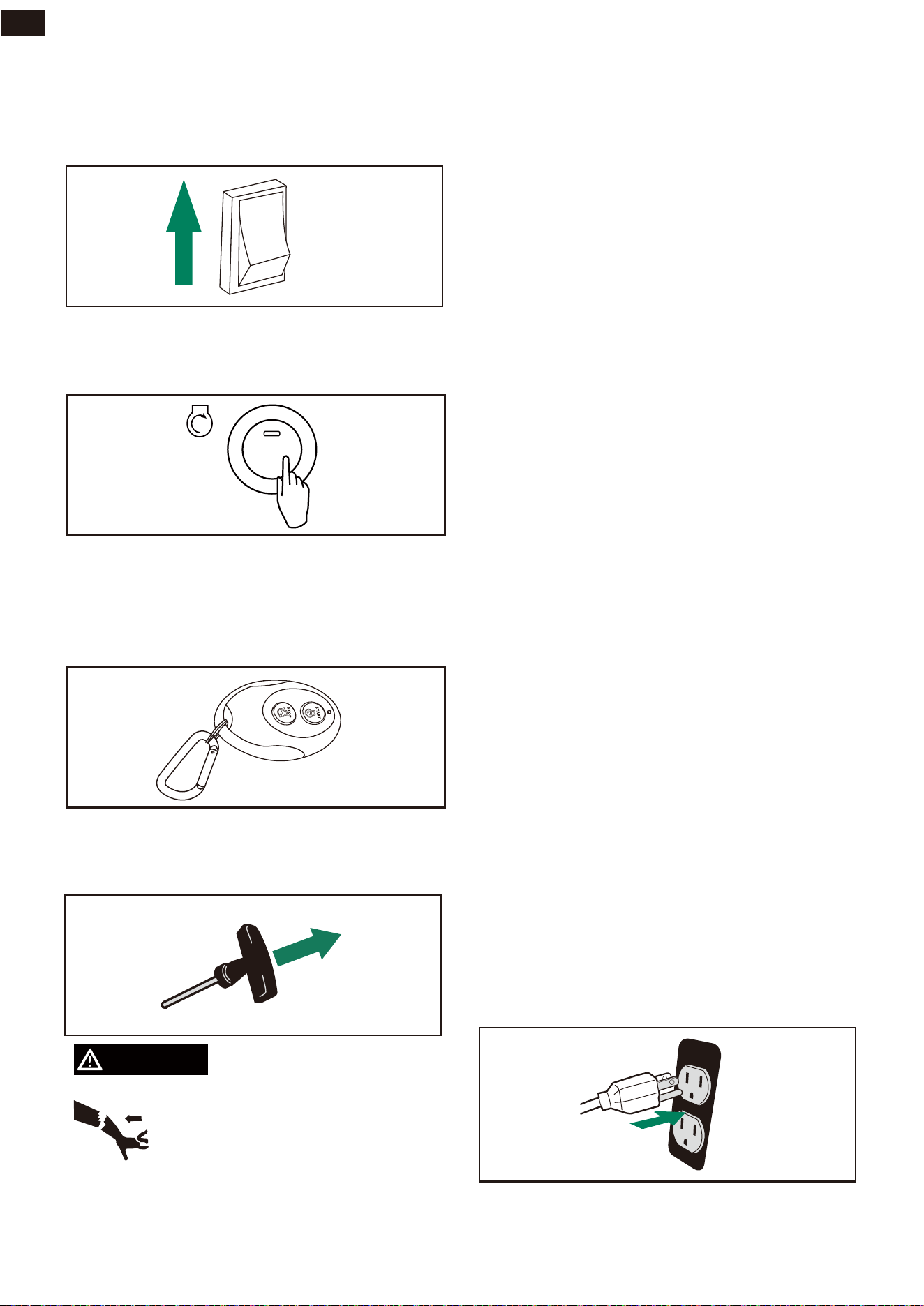
5. Turn the Engine Switch to “ON” position.
6c. Recoil Start
Pull the starter cord slowly until resistance is
felt and then pull rapidly.
6b. Remote Start
6a. Electric Start
START
STOP
ENGINE
Turn and hold the ENGINE START/STOP
switc for 3-5 seconds until the engine start.h
Turn and hold the REMOTE START switch
for 3 seconds until the engine start. 164-feet
(50 meters) long-distance control, meeting
the FCC requirements.
WARNING
Starter cord kickback (rapid
retraction) will pull hand and arm
toward engine faster than you can
let go which could cause broken
bones, fractures, bruises, or
sprains resulting in serious injury.
When starting engine, pull cord slowly until
resistance is felt and then pull rapidly to
avoid kickback.
NOTE:
If engine starts after 3 pulls but fails to run.
Or if unit shuts down during operation, make
sure unit is on a level surface and check for
proper oil level in crankcase. This unit may
be equipped with a low oil protection
device. If so, oil must be at proper level for
engine to start.
NOTE:
When applying a load, do not exceed the
maximum wattage rating of the generator
when using one or more receptacles. Also,
do not exceed the amperage rating of any
one receptacle.
Do not apply heavy electrical load during
break-in period (the first five hours of
operations).
Connecting Electrical Loads
This unit has been pretested and adjusted to
handle its full capacity. Before starting the
generator, disconnect all loads. Apply load
only after generator is running. Voltage is
regulated via the engine speed adjusted at
the factory for correct output. Re-adjusting
will void warranty.
1. Let engine stabilize and warm up for a
few minutes after starting.
2. Ensure circuit breaker on control panel is
in on position.
3. Plug in and turn on the desired 120 or
240 Volt AC, single phase, 60Hz electri-
cal loads. It is better to attach the item
with largest load first.
ON
OFF
OPERATION
24
EN
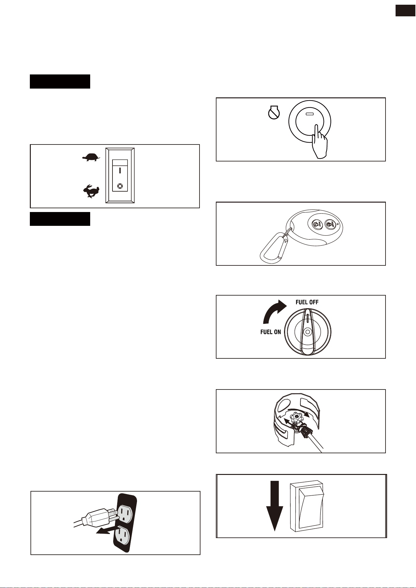
Low Idle Switch
Stopping the Engine
NOTICE
Always start the generator with LOW IDLE
SWITCH on OFF position. Allow the engine
speed to stabilize and the OUTPUT READY
INDICATOR LED to illuminate green before
switching LOW IDLE Switch to ON position.
NOTICE
For periods of high electrical load or mo-
mentary fluctuations, the LOW IDLE Switch
should be turned OFF.
1. Make sure all loads are disconnected
from the generator.
NOTE:
LOW IDLE minimizes fuel consumption and
noise by adjusting the engine speed (RPM)
to the minimum required for the current
load. Turn LOW IDLE Switch to ON position
when powering small appliances with con-
tinuous loads such as a computer or electric
light. Turn LOW IDLE Switch to OFF position
when powering large surge loads such as an
air conditioner or electric pump. Be certain
that the OUTPUT READY INDICATOR LED is
illuminated green before turning the switch
to ON position. If no load is present, the gen-
erator speed (RPM) will drop to idle speed.
The generator will detect loads as they are
applied and increase engine speed (RPM).
To run the generator at maximum power and
speed (RPM), push the LOW IDLE Switch to
the OFF position.
START
STOP
ENGINE
4. Turn the LPG cylinder knob to close
position.
5. Turn the Engine Switch to “OFF” position.
2a. Electric button operation
Push and hold the START/STOP button for
3-5 seconds until the engine stop.
2b. Remote control operation
Push STOP on the remote start key fob for 3
seconds until the engine stop.
3. Turn the Fuel Switch to the “OFF”
position.
ON
OFF
OPERATION
25
EN
WARNING
DANGER
Fuel and its vapors are extremely flammable
and explosive which could cause burns, fire
or explosion resulting in death or serious
injury.
DO NOT stop engine by moving choke
control to “START” position.
Low Oil Shutdown
Do Not Overload Generator
NOTE:
If the engine will not be used for a period of
two weeks or longer, please see the Storage
section for proper engine and fuel storage.
If the engine oil drops below a preset level,
an oil switch will stop the engine. Check oil
level with dipstick.
If oil level is between LOW and HIGH mark on
dipstick:
1. DO NOT try to restart the engine.
2. Contact an Authorized Service Dealer.
3. DO NOT operate engine until oil level is
corrected.
If oil level is below LOW mark on dipstick:
1. Add oil to bring level to HIGH mark.
2. Restart engine and if the engine stops
again a low oil condition may still exist.
DO NOT try to restart the engine.
3. Contact Customer Service.
4. DO NOT operate engine until oil level is
corrected.
Overloading a generator in excess of its
rated wattage capacity can result in damage
to the generator and to connected electrical
devices.
To prolong the life of your generator and
attached devices, follow these steps to add
electrical load:
1. Start the generator with no electrical
load attached.
2. Allow the engine to run for several min-
utes to stabilize.
3. Plug in and turn on the first item. It is best
to attach the item with the largest load
first.
4. Allow the engine to stabilize.
5. Plug in and turn on the next item.
6. Allow the engine to stabilize.
7. Repeat steps 5-6 for each additional
item.
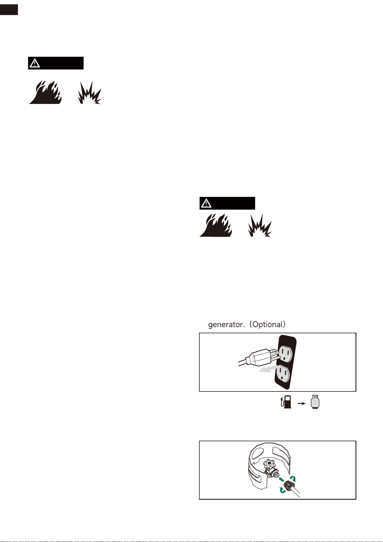
2a. Gasoline to LPG
Changing Fuels
• Gasoline, gasoline vapor and LPG are
highly flammable and explosive.
• Fire or explosion can cause severe burns
or death.
• DO NOT add gasoline to the gasoline
tank or connect the LPG hose to the gen-
erator while the generator is running.
1. Disconnect all electrical loads from the
2a1. Connect the LPG gas hose to the LPG
fuel source.
OPERATION
26
EN
WARNING
NOTICE
Parallel Operation
(2 x VS12000411 Models)
Fire and electrocution hazard. Never con-
nect or disconnect the parallel cord leads
when a generator is running. Do not parallel
more than two generators. Use only AIVOLT
generators for paralleling.
Paralleling this generator to a generator that
is not compatible can cause a low voltage
output that can damage tools and
appliances powered by the generator. Do
not connect or disconnect parallel cables
while the generator is running to avoid
damage.
Parallel operation gives you the ability to link
this generator to a compatible AIVOLT
generator for combined running and starting
power output. Use only the AIVOLT
approved cables for parallel operation. For
single generator operation, the parallel
operation cable must be removed.
2a3. Fully open the LPG cylinder knob.
2b.LPG to Gasoline
2b1. Make certain the LPG tank is fully
closed.
2b2. Flip the fuel source switch on the side
panel to the gasoline position.
2b3. Turn the Fuel Switch to the“ON”
position.
12V
OFF OFF OFF OFF
45"35
4501
&/(*/&
2a4. Flip the fuel source switch on the side
panel to the LPG position.
2a2. Use LPG hose with regulator to
connect LPG tank and generator.
GAS
LPG
GAS
LPG
OPERATION
27
EN
NOTE: Only connect two identical (same
model) generators together for parallel
operation.
WARNING
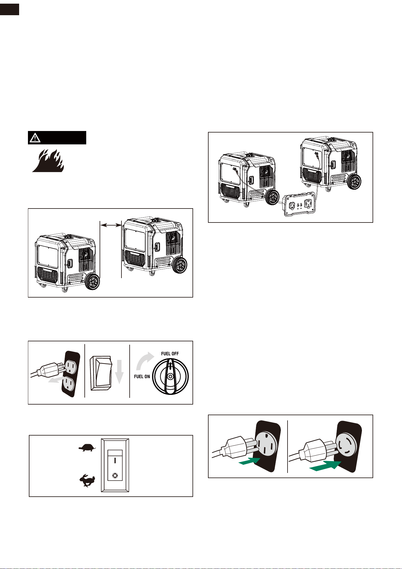
1. Align the two inverters on a firm, flat and
level surface at a minimum 20 inch apart.
Set up and Operation
If not spaced apart, the exhaust heat from
one generator discolors or melt the plastic
shell on other generator.
4. Lift the parallel outlet cover on both
generators. Plug the black and red parallel
cable leads to the black parallel ports on
each corresponding generator control
panel. Connect the yellow/green leads to
the ground terminal on each generator
and tighten the nut.
Always unplug all loads before stopping the
generators.
5. Start one of the generators and wait until
the OUTPUT READY INDICATOR LED
illuminates.
6. Start the second generator and wait until
the OUTPUT READY INDICATOR LED
illuminates before connecting a load.
7. Plug in the 120 or 240 Volt AC, single
phase, 60Hz electrical loads into parallel
kit receptacles and turn on first load.
Allow generator output to stabilize before
plugging in the next load.
20”
2. Both generators to be turned off and all
electrical loads disconnected before paral-
leling operation.
3. Make sure the LOW IDLE switch is in the
OFF position on both generators.
NOTE:
It is strongly recommended to plug in devic-
es with the largest output first and the small-
est output last to help prevent overloading
the inverters. Do not exceed maximum watt -
age rating of inverters, parallel kit and
receptacles.
MAINTENANCE AND STORAGE
28
EN
NOTICE
MAINTENANCE SCHEDULE
Walk-Around Inspection
Before starting the engine perform a visual
inspection of the unit. Look for:
• Proper engine oil level
• Proper fuel level
• Fluid leaks
• Loose clamps and bolts
• Cracked fuel line
• Loose or frayed wiring
• Built up debris
NOTE:
Adverse conditions will require more
frequent services.
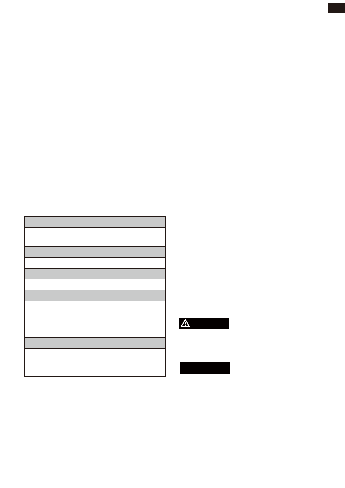
Before Each Use
* To be performed by authorized service
center
Check engine oil level
Walk-around inspection
First 5 Hours (Break-In)
Change engine oil
First 25 Hours or First Month
Change engine oil
Every 100 Hours or 6 Months
Change engine oil
Clean Air Filter
Inspect/Adjust/Replace Spark plug
Inspect/Clean/Replace Spark Arrester
Every 200 Hours or 12 Months
Replace Air filter
Replace Spark Plug
Inspect/Adjust Valve Clearance*
Regular Maintenance will improve the per-
formance and extend the life of your gener-
ator. Follow maintenance schedule intervals
whichever occurs first according to use.
NOTE:
Maintenance should be performed more
frequently when generator is used in dusty
areas.
When generator has exceeded the maximum
figures specified in the table, maintenance
should still be cycled according tothe inter-
vals of time or hours stated herein.
General Recommendations
Regular maintenance will improve the
performance and extend the life of the
generator. See any authorized dealer for
service.
The generator's warranty does not cover
items that have been subjected to operator
abuse or negligence.
To receive full value from the warranty, the
operator must maintain generator as
instructed in this manual. Some adjustments
will need to be made periodically to properly
maintain your generator. All service and
adjustments should be made at least once
each season. Follow the requirements in the
Maintenanc Shedule chart above.
ENGINE MAINTENANCE
To prevent accidental starting, remove and
ground spark plug wire before performing
any service.
Engine Oil Level Check
CAUTION
Avoid skin contact with engine oil. Wear pro-
tective clothing and equipment. Wash all
exposed skin with soap and water.
Always use the specified engine oil. Failure
to use the specified engine oil can cause
accelerated wear and/or shorten the life of
the engine.
NOTE:
Change oil every month when operating
under heavy load or high temperatures.
Clean the air filter more often under dirty or
dusty operating conditions.
Replace air filter if they cannot be adequate-
ly cleaned.
MAINTENANCE AND STORAGE
29
EN
WARNING
CAUTION
-20 0 20 40 60
Ambient temperature
Recommended Engine Oil Type
80 100 120
-28.9
°F
°C
-17.8 -6.7 4.4 15.6 26.7 37.8 48.9
10W-30
5W-30 Full Synthetic
10W-405W-30
Check the engine oil level before each use or
every 8 hours of operation.
1. Place the generator on a level surface
and allow the engine to cool for several
minutes.
2. Loosen the screws at the side of the left
maintenance cover. Remove cover and
set aside.
3. With a damp rag, clean around the oil
dipstick.
4. Remove the oil dipstick.
5. Wipe the dipstick clean, then screw dip-
stick into filler neck. Remove the dipstick
and verify that the oil level is within safe
operating range.
6. If low, add recommended engine oil
incrementally and recheck until the level
is between the L and H marks on the dip-
stick. DO NOT overfill. If over the full
mark on the dipstick, drain the oil to
reduce the oil level to the full mark.
7. Replace the oil dipstick and hand-tighten.
Change Engine Oil
Change engine oil per maintenance sched-
ule. If you are using your generator under
extremely dirty or dusty conditions, or in
extremely hot weather, change the oil more
often.
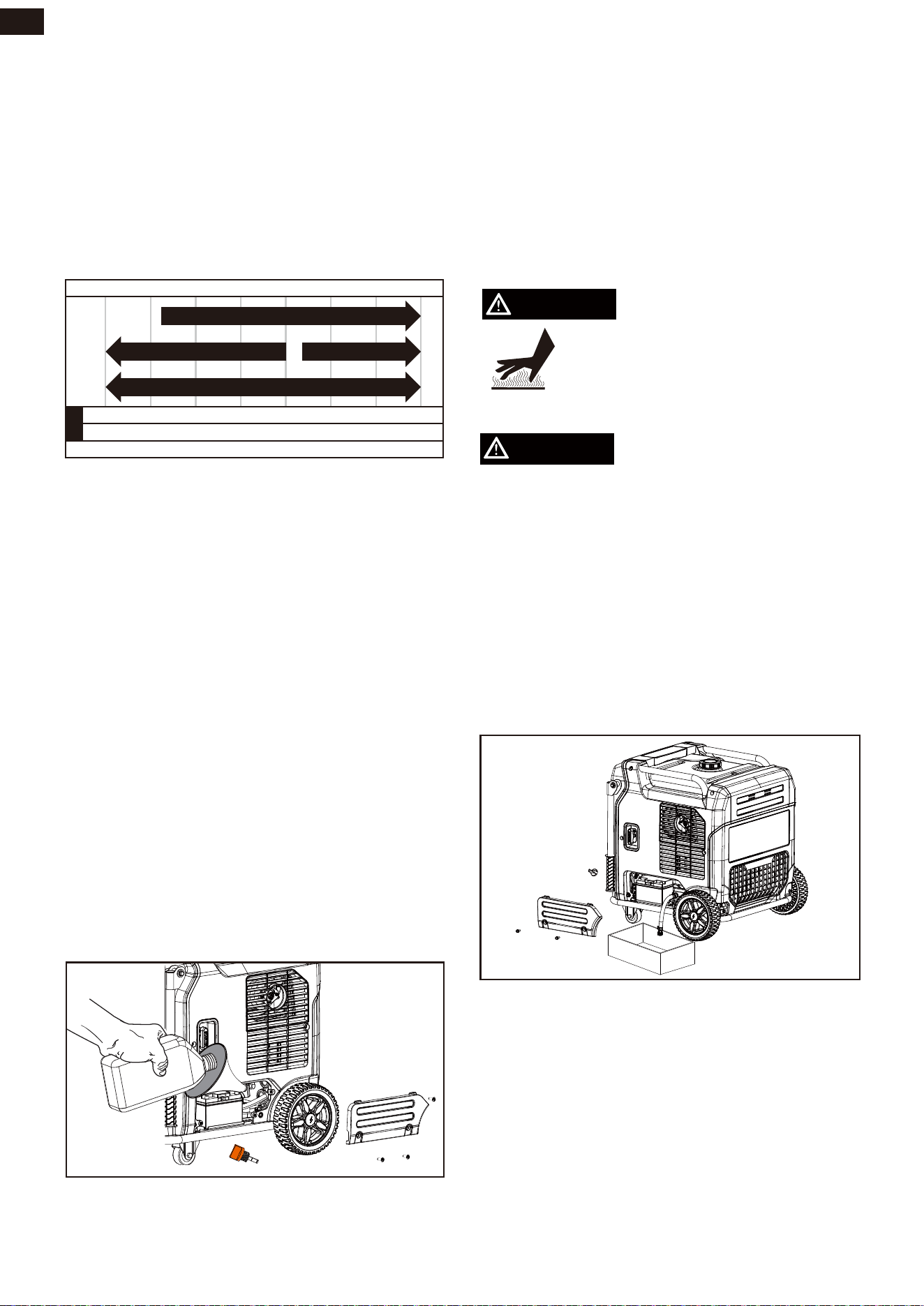
Risk of burns. Allow engine to cool
before draining oil or coolant.
Failure to do so could result in
death of serious injury.
Avoid prolonged or repeated skin contact
with used motor oil.
1. Open the right maintenance cover.
2. Use a suitable container under the gen-
erator.
3. Find the oil drain pipe, unscrew the cap,
and drain the oil into the container.
4. Reinstall the cap and put the pipe back
into the generator.
5. Add new oil then tighten the oil dipstick
and close the maintenance cover.
NOTE: Drain the lubricant while the engine
is still warm but not hot. Warm lubricant will
drain quickly and more completely.
If contaminated or deteriorated oil is used or
the quantity of the engine oil is not suffi-
cient, engine damage will
result and its life will be greatly shortened.
Maximum oil capacity: 40.6 fl.oz (1.2 L)
When using the generator under extreme,
dirty, dusty conditions or in extremely hot
weather, change the oil more frequently.
Ambient air temperature will affect engine
oil performance. Change the type of engine
oil used based on weather conditions.
MAINTENANCE AND STORAGE
30
EN
WARNING
CAUTION
Air Filter Maintenance
Battery Replacement
For proper performance and long life, keep
air filter clean.
1. Loosen the screws at the side of the
maintenance cover. Remove cover and
set aside.
2. Unsnap the air filter cover clip, pulling the
cover down and off the unit, remove air
filter cover and set aside.
3. Remove the air filter.
4. Wash the air filters with warm, soapy
water. Rinse and squeeze to dry.
5. Reinstall the air filters.
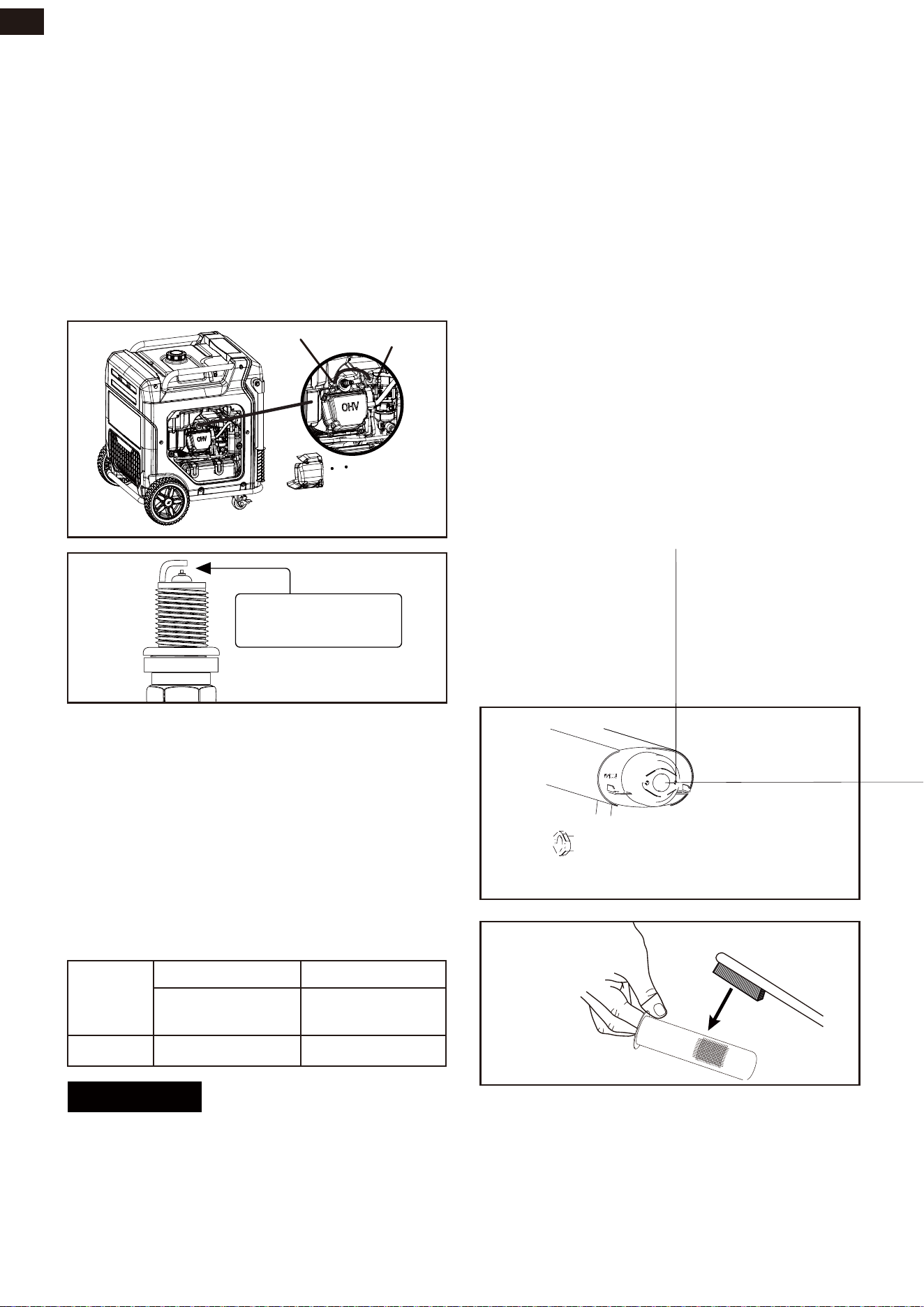
Spark Plug Maintenance
1. The spark plug must be properly gapped
and free of deposits in order to ensure
proper engine operation.
2. To check:
3. 1. Loosen the screws at the side of the
maintenance cover.
4. Remove the spark plug cap (B).
5. Clean any dirt from around base of spark
plug.
6. Remove spark plug (A) using provided
wrench.
7. Inspect spark plug for damage, and clean
with a wire brush before reinstalling. If
insulator is cracked or chipped, spark
plug should be replaced.
8. Measure plug gap. The correct gap is
0.028-0.031 in. (0.7-0.8 mm). To widen
gap, if necessary, carefully bend the
ground (top) electrode. To lessen gap,
gently tap ground electrode on a hard
surface.
Burn hazard. The battery contains sulfuric
acid (electrolyte) which is highly corrosive
and poisonous.Wear protective clothing and
eye protection when working near the bat-
tery. Keep children away from the battery.
Battery posts, terminals contain lead and
lead compounds. Wash hands after handling.
1. Turn the battery cover knob to the
unlocked position, and remove the
access cover from the right panel.
2. Loosen the rubber belts and pull out the
battery.
3. Remove the cable from the battery, con-
nect the red cable to the
positive(+) and
the black cable to the negative (-) of the
new battery, and then connect the bat-
tery to the generator.
NOTICE
Dispose of the used battery properly
according to the guidelines established by
your local or state government.
4. Return the battery into position and use
the rubber belts to fasten the battery.
5. Reinstall and secure the battery access
cover.
1. The spark plug must be properly gapped
and free of deposits in order to ensure
proper engine operation.
2. To check:
3. 1. Loosen the screws at the side of the
maintenance cover.
4. Remove the spark plug cap (B).
5. Clean any dirt from around base of spark
plug.
6. Remove spark plug (A) using provided
wrench.
7. Inspect spark plug for damage, and clean
with a wire brush before reinstalling. If
insulator is cracked or chipped, spark
plug should be replaced.
8. Measure plug gap. The correct gap is
0.028-0.031 in. (0.7-0.8 mm). To widen
gap, if necessary, carefully bend the
ground (top) electrode. To lessen gap,
gently tap ground electrode on a hard
surface.
9. Seat spark plug in position; thread in by
hand to prevent cross-threading.
10.Tighten with wrench to compress
washer. If spark plug is new, use 1/2 turn
to compress washer appropriate amount.
If reusing old spark plug, use 1/8 to 1/4
turn for proper washer compression
11.Reinstall the spark plug cap (B).
MAINTENANCE AND STORAGE
31
EN
9. Seat spark plug in position; thread in by
hand to prevent cross-threading.
10.Tighten with wrench to compress
washer. If spark plug is new, use 1/2 turn
to compress washer appropriate amount.
If reusing old spark plug, use 1/8 to 1/4
turn for proper washer compression
11.Reinstall the spark plug cap (B).
0.7 - 0.8 mm
0.028 - 0.031 in.
A - Spark plug
B - Spark plug cap
A
B
NOTE: An improperly tightened spark plug
will become very hot and could damage the
engine.
NOTICE
0.004~0.006 inch
0.1~0.15 mm
0.004~0.008 inch
0.15~0.2 mm
10-12 N·M 10-12 N·M
Intake Valve Exhaust Valve
Valve
Clearance
Torque
Valve Clearance
Cleaning the Spark Arrestor
Important: Please contact Authorized Ser-
vice Center for service assistance. Proper
valve clearance is essential for prolonging
the life of the engine. Check valve clearance
per maintenance schedule.
Checking and adjusting valve clearance
must be done when the engine is cold.
1. Allow the engine to cool completely
before servicing the spark arrestor.
2. Loosen the screws on right maintenance
cover. Remove the cover and set it aside.
3. Loosen the screw (A) to be able to
remove the clamp (B) and cover plate (C).
4. Remove the spark arrestor screen (C).
5. Carefully remove the carbon deposits
from the spark arrestor screen with a
wire brush.
6. Replace the spark arrestor if it is dam-
aged.
7. Position the spark arrestor on the muffler
and reinstall the muffler cover with the
screws removed in step 2.
NOTE: This product is equipped with a spark
arrestor that has been evaluated by the
USDA Forest Service; however, product
users must comply with Federal, State, and
local fire prevention regulations. Check with
appropriate authorities. Contact customer
service or a qualified service center to pur-
chase a replacement spark arrestor.
EN
DO NOT RETURN THIS PRODUCT TO THE STORE
If you have questions or need assistance, please call customer service at
+1 (689) 888-7131 or service emai [email protected]
ENGINE SWITCH
FUEL
CHOICE
VOLTAGE SELECTOR SWITCH
DIGITAL DISPLAY
PARALLEL CONNECT
120V AC 20A
5-20R GFCI
120V AC 30A
L5-30R
GND
DC 12V
ATS
CIRCUIT BREAKER
THERMAL
PROTECTION
THERMAL
PROTECTION
THERMAL
PROTECTION
CIRCUIT BREAKER
120/240V AC 30A
L14-30R
AC 120/240V
50A 14-50R
BATTERY
CHARGER
INLET
PUSH-BUTTON
LPG
INLET
FUEL SWITCH
ECO
MODE
ENGINE
START
STOP
AGen11250DFc-i
11250 WATT
PEAK WAT TS / VATIO P ICO
RUNNING WAT TS / VATIO S DE CONTINUO S
11250 9000
PEAK WAT TS / VATIO P ICO
RUNNING WAT TS / VATIO S DE CONTINUO S
DUAL
FUEL
SERIES