To reduce the risk of fire, electric shock or injury to persons using this freezer, read all instructions and follow
basic safety precautions before using the unit, including the following:
Do not modify the plug provided with the unit. If it will not fit the outlet,
have a proper outlet installed by a qualified electrician.
Do not position equipment so it is difficult to disconnect from the power supply.
While under warranty, do not attempt to repair or replace any part of the
freezer for servicing without first contacting the So-Low Service Department.
BEFORE CALLING THE MANUFACTURER’S TECHNICAL SUPPORT DEPARTMENT
Please have the model number of the unit, box identification number, and serial number ready as
well as the problem description. The model, serial number and box id number can be found on
the serial tag, which is located on the interior left upper wall, or back of the unit.
SAVE THESE INSTRUCTIONS
♦
● PRE-INSTALLATION INFORMATION…...…………………………………...
♦
● MOISTURE DURING THE SUMMER SEASON…….……………………...
♦
● DOOR GASKET REPLACEMENT………...……………………………….….
● MONITOR PROBE FOR FIELD INSTALLATION…………………...……….
♦
● CLEANING AND DEFROST PROCEDURE………….…………………….
● CLEANING THE CONDENSER…….……………………………………….
♦
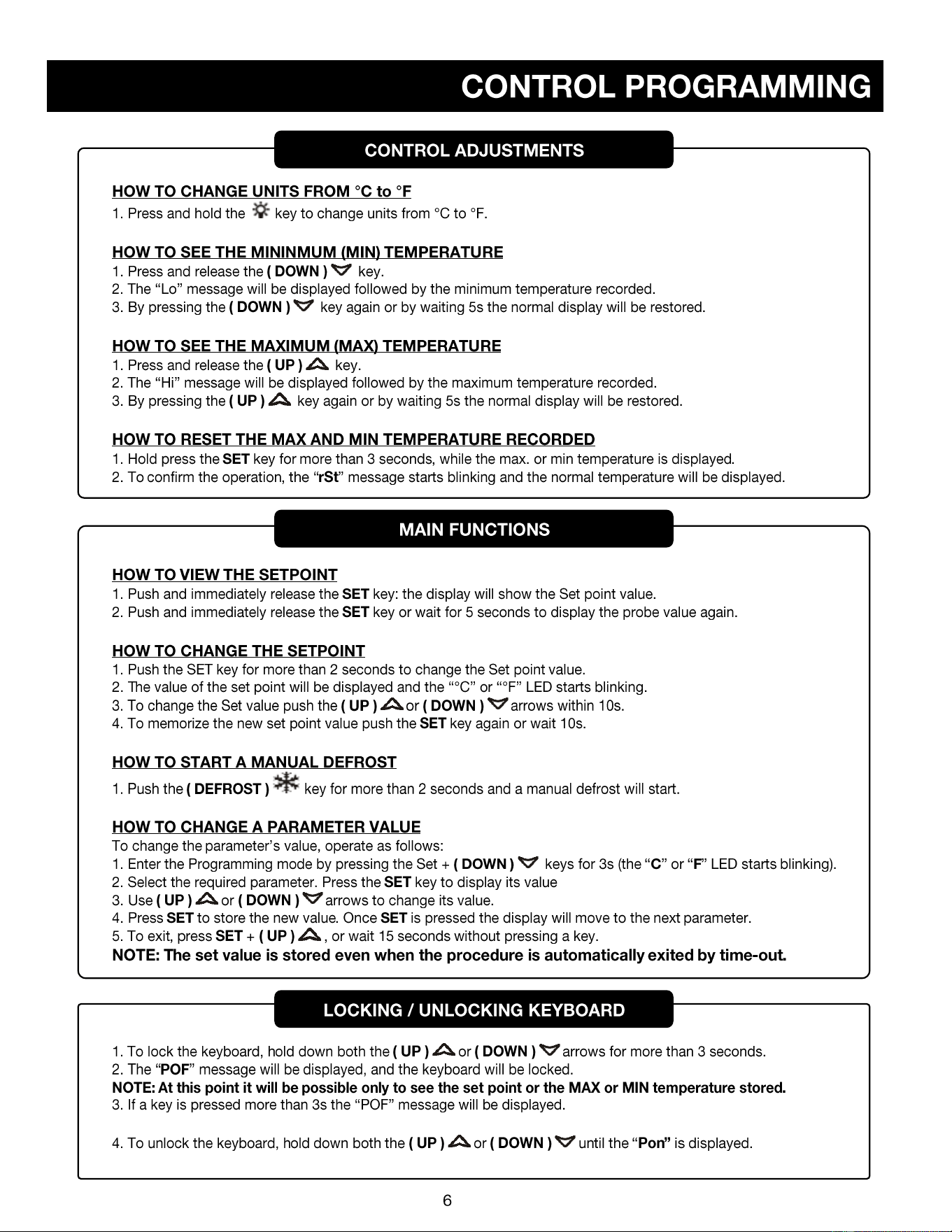
● CONTROL PROGRAMMING………………………………………………….
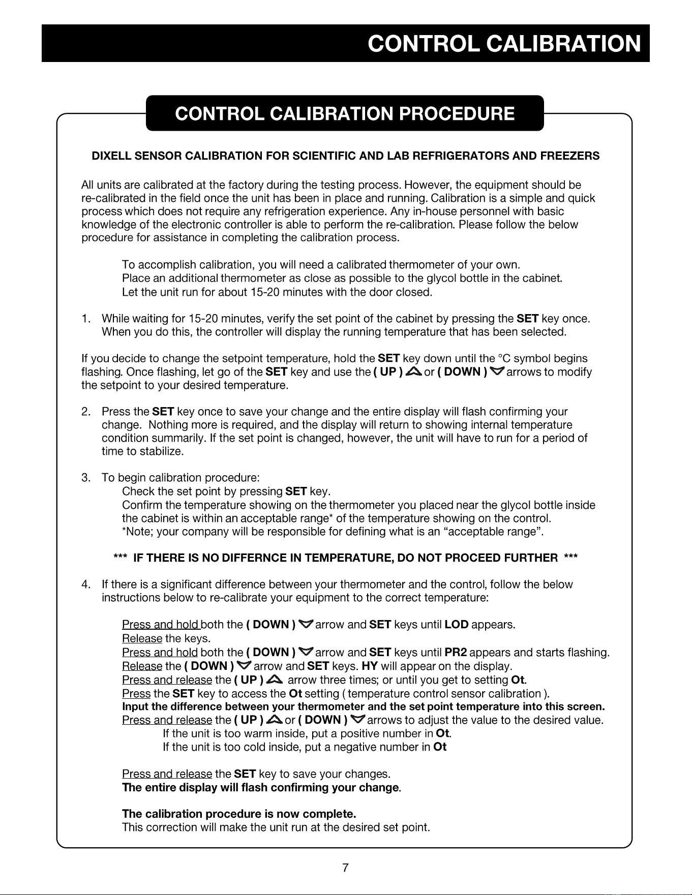
● HOW TO CALIBRATE THE CONTROL……….……………………………...
♦ CONTROL SETTINGS
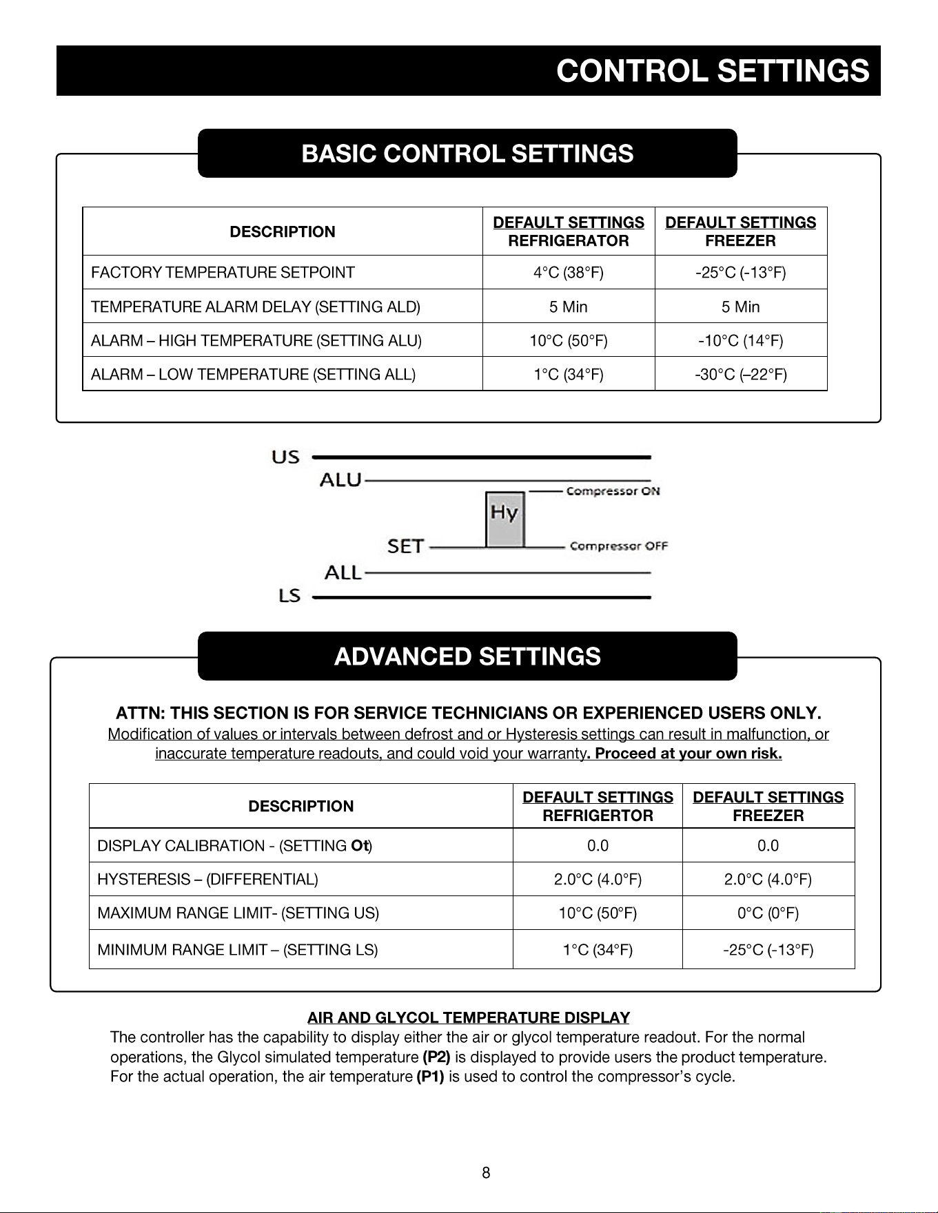
● BASIC CONTROL SETTINGS….…………………………………………….
● ADVANCED SETTINGS……...………………………………………………...
♦
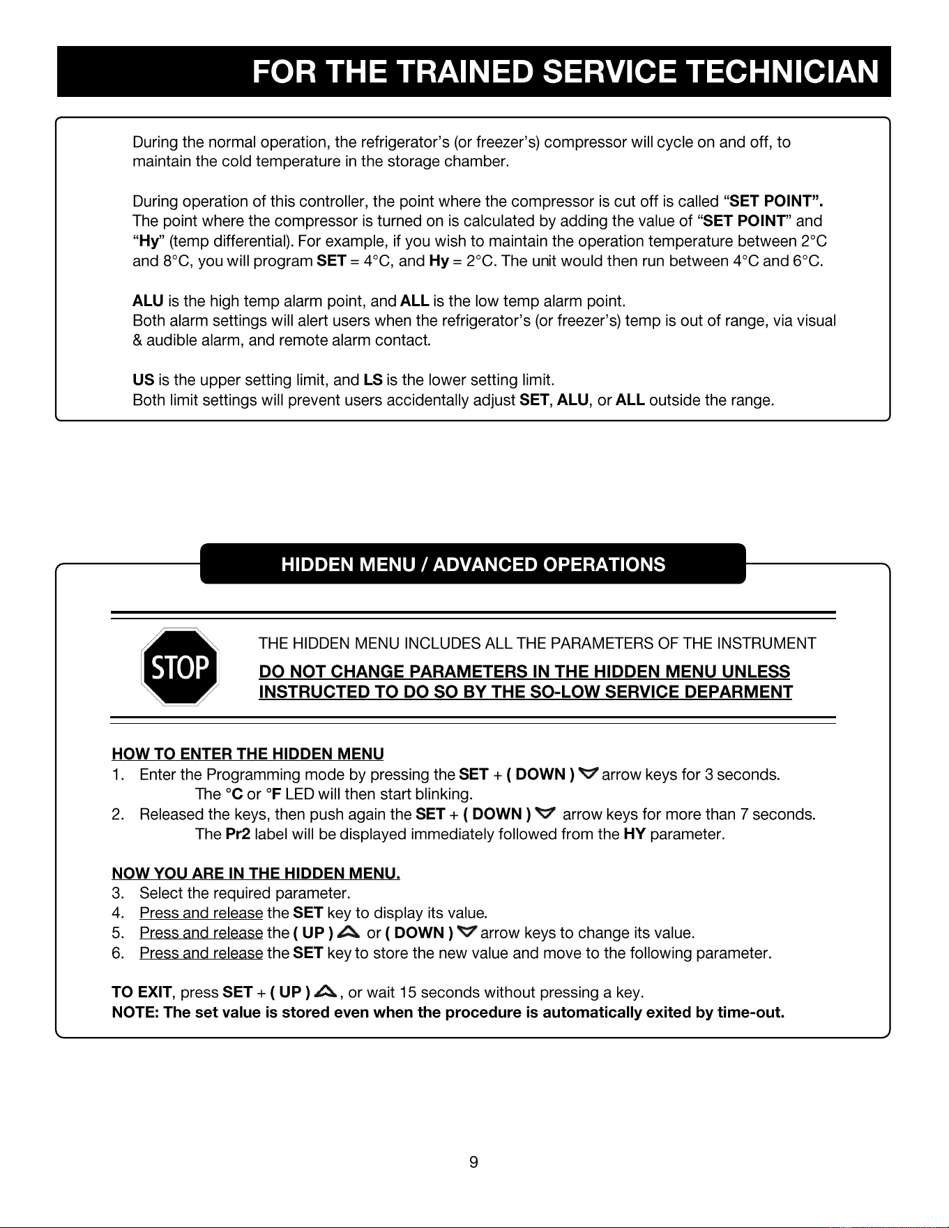
● THE HIDDEN MENU……………………………………………………………
♦
MV4-2UCRDA
MV4-2UCRGDDA
MV4-6UCRDA
MV4-6UCRGDDA
MV20-2UCF
MV25-4UCF
MV30-4UCF
MV40-4UCF
DHK4-10GD
DHK4-10SD
DHK30-10SD
DHK20-20MDP
DH-9RFDA
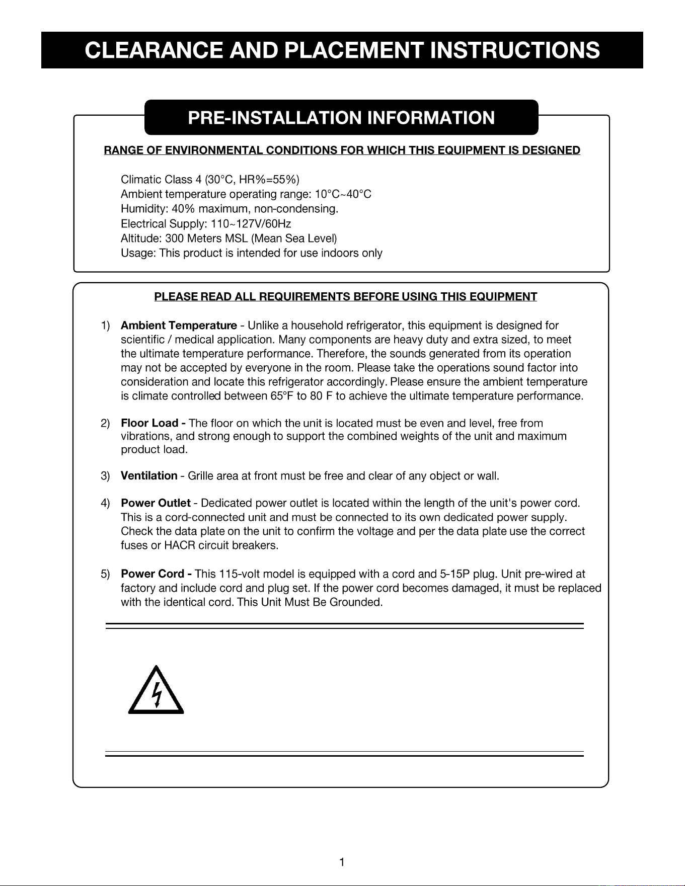
115 VOLTS
60 HERTZ
1 PHASE
(SUPPLY VOLTAGE
SHOULD NOT VARY
MORE THAN 5%
FROM SERIAL PLATE
RATINGS.)
15 AMP
DEDICATED
LINE
NEMA 5-15
(Unit pre-
wired at
factory
includes
cord and
plug set.)
•
•
•
•
•
•
°
CAUTION
DO NOT CONNECT TO GFI / GFCI OUTLETS. CONNECTION TO THAT
TYPE OF OUTLET CAN RESULT IN PRODUCT LOSS DUE TO UNSAFE
CABINET TEMPERATURE WHEN GFI DEVICE TRIPS FROM MOISTURE.
DO NOT USE EXTENSION CORDS AND DO NOT DISABLE OR BY-PASS
GROUND PRONG ON ELECTRICAL PLUG
ELECTRICAL PLUG
• PLUG THE UNIT INTO THE PROPER OUTLET WITH AN ADEQUATE POWER SUPPLY.
• THIS UNIT REQUIRES A DEDICATED ELECTRICAL LINE.
• UNIT PRE-WIRED AT FACTORY AND INCLUDE CORD AND PLUG SET.
CAUTION
DISCONNECT THIS UNIT FROM THE POWER SUPPLY
BEFORE PERFORMING MAINTENANCE ON THE UNIT.
•
•
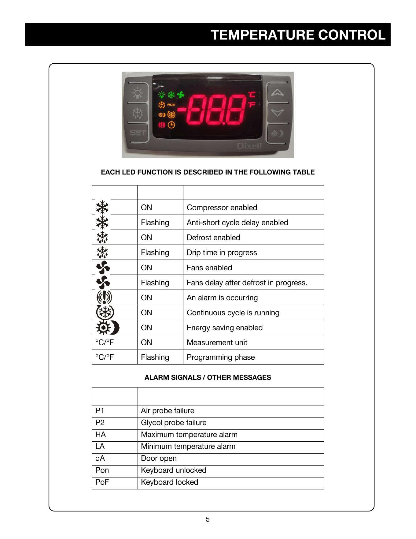
LED
MODE
FUNCTION
MESSAGE
CAUSE
•
•
•
•
•
•
•
•
•
•
•
o
o
•
•
•
•
•
❖
❖
•
•
•
•
•
•
•
•
•
•
•
•
•

TEMPERATURE TO RESISTANCE
CHART NTC THERMISTOR
Temp C Temp F Resistance Ohms
- 50 - 58 329.5
- 45 - 50 247.7
- 40 - 40 188.5
- 35 - 31 144.1
- 30 - 22 111.3
- 25 - 12.5 86.43
- 20 - 4 67.77
- 15 5 53.41
- 10 14 42.47
- 5 23 33.9
0 32 27.28
5 41 22.05
10 50 17.96
15 59 14.69
20 68 12.09
25 77 10.00
30 86 8.313
35 95 6.94
40 104 5.827
45 13 4.911
50 122 4.160
55 131 3.536
60 140 3.020
65 149 2.588
70 158 2.228
75 167 1.924
80 176 1.668
85 185 1.451
90 194 1.266
95 203 1.108
100 212 0.9731
105 221 0.8572
110 230 0.7576
All Resistance is k or (x1000)