BOD INCUBATORS
Installation - Operation Manual
SRI3P, SRI3P-2, SRI6P, SRI6P-2, SRI20P, SRI20P-2
2 | Page
Not for Fly Cultivation
This unit is not designed to hold fruit flies (
Drosophila melanogaster)
. Use with flies voids the
manufacturing warranty and risks damaging the unit.
Other incubator models in the SRIP family are specifically manufactured for fly applications. Talk to
your distributor or customer service representative to identify a model compatible with your study
or production model.
Pictured on Cover: SRI3P left, SRI6P right
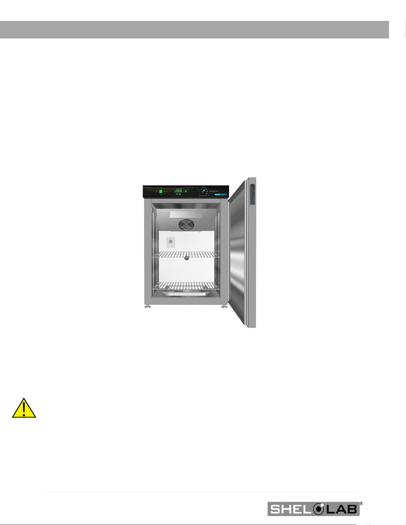
SRI6P
48TWarning:48T This product contains chemicals, including triglycidyl isocyanurate, known to the State
of California to cause cancer as well as birth defects or other reproductive harm. For more
information, go to
33Twww.P65Warnings.ca.gov33T.
48T¡Advertencia! Este producto contiene sustancias químicas, incluido el triglicidil isocianurato, que el
estado de California sabe que causa cáncer, así como defectos de nacimiento u otros daños
reproductivos. Para obtener más información, visite www.P65Warnings.ca.gov
48T.
Avertissement! Ce produit peut vous exposer à des produits chimiques, dont l'isocyanurate de
triglycidyle, reconnu par l'État de Californie pour provoquer le cancer, des anomalies congénitales ou
d'autres problèmes de reproduction. Pour plus d'informations, visitez le site www.P65Warnings.ca.gov.

3 | Page
Refrigerated BOD Incubators
100 – 120 Voltage Models: SRI3, SRI6P, SRI20P
220 – 240 Voltage Models: SRI3P-2, SRI6P-2, SRI20P-2
Part Number (Manual) 4861666-1
Revision: August 13, 2024

4 | Page
TABLE OF CONTENTS
MODEL CERTIFICATIONS ........................................................................................................... 7
Electromechanical and Heating Safety ............................................... Error! Bookmark not defined.
CE Compliant ................................................................................... Error! Bookmark not defined.
UKCA Compliant ............................................................................... Error! Bookmark not defined.
ISO Certified Manufacturer ............................................................................................................... 7
INTRODUCTION ......................................................................................................................... 9
Read this Manual ............................................................................................................................. 9
Safety Considerations and Requirements .......................................................................................... 9
Contacting Assistance .................................................................................................................... 11
Manufacturing Warranty ................................................................................................................ 11
Engineering Improvements ............................................................................................................ 11
Reference Sensor Device ............................................................................................................... 12
RECEIVING YOUR UNIT ...........................................................................................................13
Inspect the Shipment .................................................................................................................... 13
Orientation Images ........................................................................................................................ 14
Recording Data Plate Information ................................................................................................... 19
INSTALLATION .........................................................................................................................21
Installation Procedure Checklist ...................................................................................................... 21
Required Ambient Conditions ......................................................................................................... 22
Required Clearances ...................................................................................................................... 23
100 – 120 Volt Unit Power Requirements ........................................................................................ 24
220 – 240 Volt Power Source Requirements .................................................................................... 25
Lifting and Handling ...................................................................................................................... 26
Removing from the Pallet ............................................................................................................... 26
Leveling ........................................................................................................................................ 26
Install the Incubator ...................................................................................................................... 27
Deionized and Distilled Water ......................................................................................................... 27
Installation Cleaning and Disinfection ............................................................................................. 27
Install the SRI20P Side Air Ducts .................................................................................................... 28
Shelving Installation ...................................................................................................................... 29
Access Port Stopper ....................................................................................................................... 32
GRAPHIC SYMBOLS ..................................................................................................................33
CONTROL PANEL OVERVIEW ...................................................................................................35
OPERATION ..............................................................................................................................37
Theory of Operation ...................................................................................................................... 37
Put the Incubator into Operation .................................................................................................... 39
Set the Temperature Setpoint ........................................................................................................ 40
Set the Over Temperature Limit (OTL) ............................................................................................ 41
Loading Samples ........................................................................................................................... 42
Chamber Power Outlet ................................................................................................................... 42
Humidifying the Incubator ............................................................................................................. 43
Condensation and the Dew Point .................................................................................................... 44
USER MAINTENANCE ................................................................................................................47
Cleaning and Disinfecting ............................................................................................................... 47
Door Components ......................................................................................................................... 48
Electrical Components ................................................................................................................... 48
Calibrate the Temperature display .................................................................................................. 49
UNIT SPECIFICATIONS ............................................................................................................53

5 | Page
Weight .......................................................................................................................................... 53
Dimensions ................................................................................................................................... 53
Capacity........................................................................................................................................ 53
Shelf Capacity by Weight ............................................................................................................... 54
Power ........................................................................................................................................... 54
Temperature ................................................................................................................................. 55
PARTS LIST...............................................................................................................................57

6 | Page
TABLE OF CONTENTS

7 | Page
MODEL CERTIFICATIONS
ISO
CERTIFIED MANUFACTURER
SHEL LAB is a brand of Sheldon Manufacturing, INC, an ISO 9001 certified manufacturer.
The model units represented in this manual were tested and found to be in conformity with the following
standards:
IEC 61010-1:2010/AMD1:2016
IEC 61010-2-010:2019

8 | Page
CERTIFICATIONS
.

9 | Page
INTRODUCTION
Thank you for purchasing a SHEL LAB incubator. We know you have many choices in today’s
competitive marketplace when it comes to constant temperature equipment. We appreciate you
choosing ours. We stand behind our products and will be here if you need us.
READ THIS MANUAL
Failure to follow the guidelines and instructions in this user manual may create a protection impairment
by disabling or interfering with the unit safety features. This can result in injury or death.
Before using the unit, read the manual in its entirety to understand how to install, operate, and
maintain the unit in a safe manner. Ensure all operators are given appropriate training before the unit
begins service.
Keep this manual available for use by all operators.
SAFETY CONSIDERATIONS AND REQUIREMENTS
Follow basic safety precautions, including all national laws, regulations, and local ordinances in your
area regarding the use of this unit. If you have any questions about local requirements, please contact
the appropriate agencies.
SOPs: Because of the range of potential applications this unit can be used for, the operator or their
supervisors must draw up a site-specific standard operating procedure (SOP) covering each application
and associated safety guidelines. This SOP must be written and available to all operators in a language
they understand.
Intended Applications and Locations: The incubators are intended for constant temperature, non-
humidified microbiological incubation applications in professional, industrial, and educational
environments. The units are not intended for use at hazardous or household locations.
Power: Your unit and its recommended accessories are designed and tested to meet strict safety
requirements.
• The unit is designed to connect to a power source using the specific power cord type
shipped with the unit.
• Always plug the unit power cord into a protective earth grounded electrical outlet
conforming to national and local electrical codes. If the unit is not grounded properly, parts
such as knobs and controls can conduct electricity and cause serious injury.
• Do not bend the power cord excessively, step on it, or place heavy objects on it.
• A damaged cord can be a shock or fire hazard. Never use a power cord if it is damaged or
altered in any way.

10 | Page
• Use only approved accessories. Do not modify system components. Any alterations or
modifications to your unit not explicitly authorized by the manufacturer can be dangerous
and will void your warranty.

11 | Page
INTRODUCTION
CONTACTING ASSISTANCE
Phone hours for Sheldon Customer Support are 6 am – 4:30 pm Pacific Coast Time (west coast of
the United States, UTC -8), Monday – Friday. Please have the following information ready when
calling or emailing Customer Support: the model number, serial number, and part number
(see page 19).
support@sheldonmfg.com
1-800-322-4897 extension 4
(503) 640-3000 extension 4
Sheldon Manufacturing, INC.
P.O. Box 627
Cornelius, OR 97113
USA
MANUFACTURING WARRANTY
For information on your warranty and online warranty registration please visit:
sheldonmanufacturing.com/warranty
ENGINEERING IMPROVEMENTS
Sheldon Manufacturing continually improves all of its products. As a result, engineering changes
and improvements are made from time to time. Therefore, some changes, modifications, and
improvements may not be covered in this manual. If your unit’s operating characteristics or
appearance differs from those described in this manual, please contact your SHEL LAB dealer or
customer service representative for assistance.

12 | Page
INTRODUCTION
REFERENCE SENSOR DEVICE
Must be purchased separately
Temperature Calibrations
If you are not using a third-party service, a reference sensor device is required for
calibrating your unit’s temperature display.
• See the Calibrating the Temperature Display procedure on page 49 for more
information.
Device Accuracy
Reference devices must meet the following standards:
• Accurate to at least 0.1°C
The device should be regularly calibrated, preferably by a third party.
Temperature Probe
Use a digital device with a wire thermocouple probe that can be introduced into the unit chamber
through the access port or door space. Select a thermocouple suitable for the application temperature
you will be calibrating at.
Why a Probe?
Reference readings taken from outside the chamber using wire temperature probes avoid chamber
door openings. Openings disrupt the chamber temperature. Each disruption requires a minimum 1-
hour wait to allow the chamber to re-stabilize before continuing.
No Alcohol or Mercury Thermometers
Alcohol thermometers do not have sufficient accuracy to conduct accurate temperature calibrations.
Never place a mercury thermometer in the unit chamber. Always use thermocouple probes.
Temperature
Reference
13 | Page
RECEIVING YOUR UNIT
INSPECT THE SHIPMENT
• When a unit leaves the factory, safe delivery becomes the responsibility of the carrier.
• Damage sustained during transit is not covered by the manufacturing defect
warranty.
• Save the shipping carton until you are certain that the unit and its accessories function
properly.
When you receive your unit, inspect it for concealed loss or damage to its interior and exterior. If
you find any damage to the unit, follow the carrier’s procedure for claiming damage or
loss.
1. Carefully inspect the shipping carton for damage.
2. Report any damage to the carrier service that delivered the unit.
3. If the carton is not damaged, open the carton and remove the contents.
4. The unit should come with an Installation and Operation Manual.
5. Verify that the correct number of accessory items have been included.
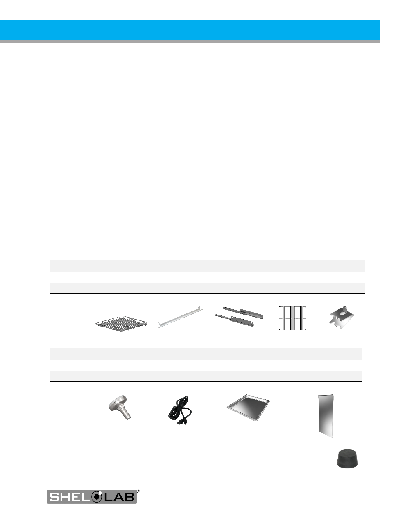
Model
Medium Shelves
Static Brackets
Sliding Brackets
Small Shelves
Shelf Clips
SRI3P
0
0
0
2
8
SRI6P
2
4
0
0
0
SRI20P
5
8
2
0
0
Model Leveling Feet Power Cord Humidification Pan Side Air Duct Panels
SRI3P
4
1
1
0
SRI6P
4
1
1
0
SRI20P
4
1
1
2
6. The incubator ships with a rubber stopper in the access port inside the incubation chamber.
Verify the presence of the stopper.
7. Carefully check all packaging for accessories before discarding.
14 | Page
RECEIVING
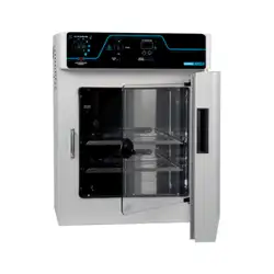
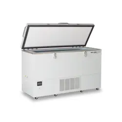
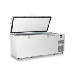
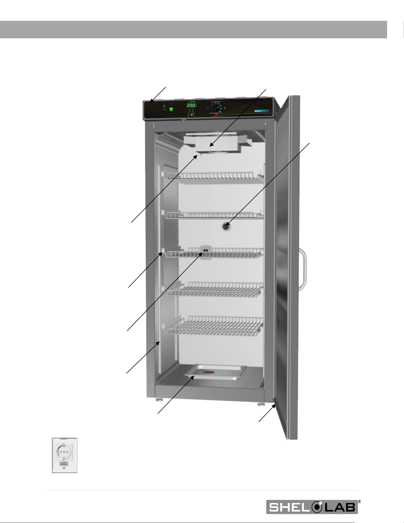
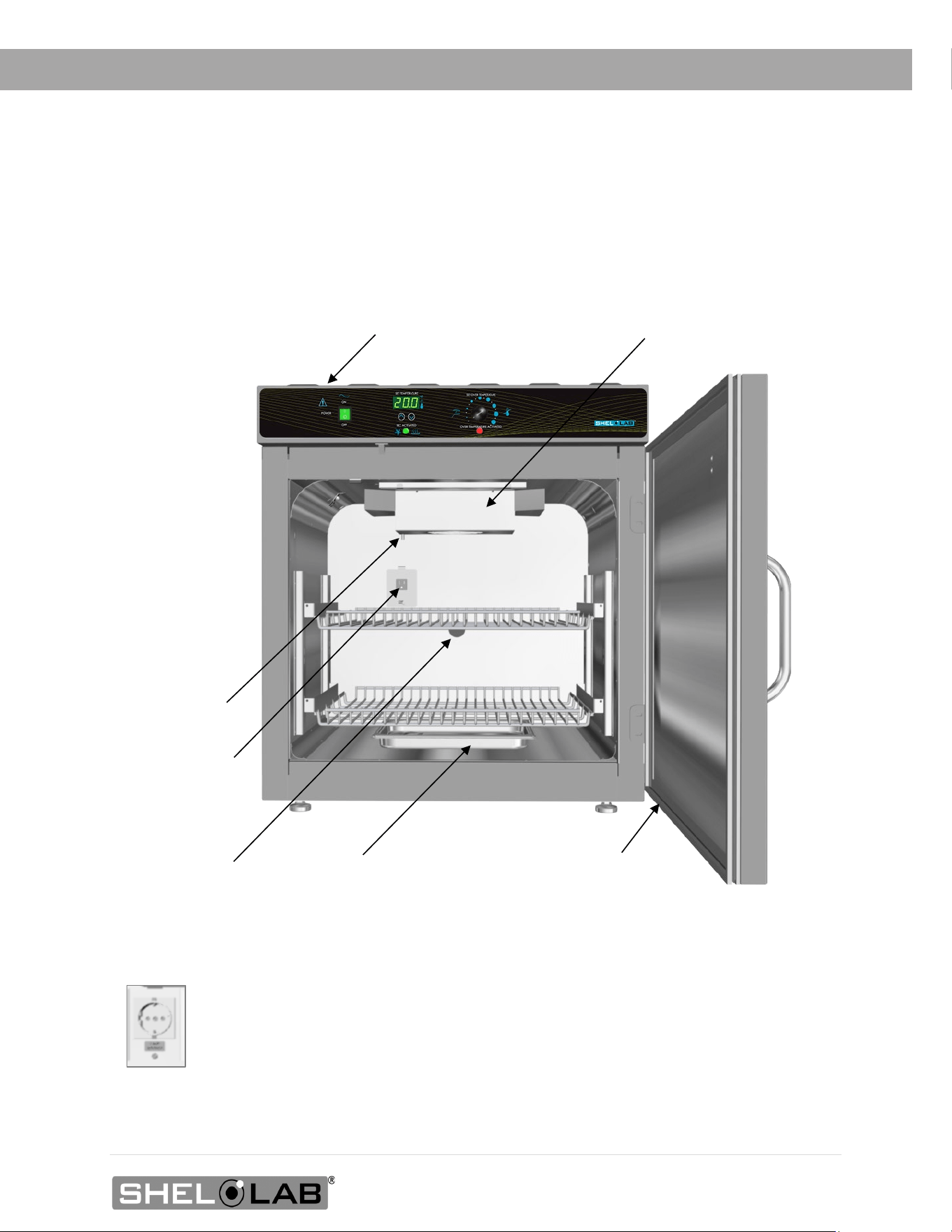
ORIENTATION IMAGES
Peltier Thermoelectric Heater – Chiller Housing
SRI20P Chamber Power
Outlet, NEMA 5-15R 100
– 120 Volt*
Shelf Mounting Bracket
Shelf Standard Rail
Door Gasket
Control Panel
Access Port
Drain Port - TEC Housing
Chamber Door
Humidification Pan
*SRI20P-2 Chamber Power Outlet, CEE7/3 220 – 240 Volt
SRI20P
s
15 | Page
RECEIVING
Drain Port -
TEC Housing
SRI6P Chamber
Power Outlet,
NEMA 5-15R
100 – 120 Volt*
Access Port
Door Gasket
Humidification Pan
*SRI6P-2 Chamber Power Outlet, CEE7/3 220 – 240 Volt
Control Panel
Peltier Thermoelectric Heater – Chiller Housing
Chamber Door
SRI6P
16 | Page
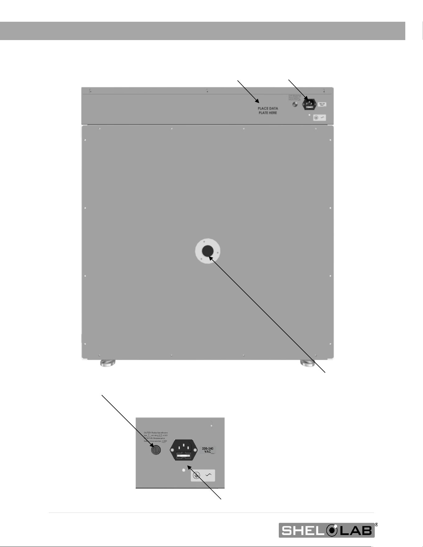
RECEIVING
Power Panel
Data Plate
Chamber Access Port
Power Panel
Closeup
Power Cord Inlet with Fuse Holder
Second Fuse Holder (220V Incubators only)
17 | Page
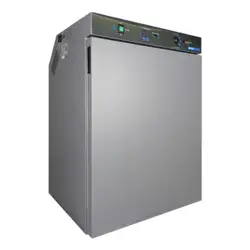
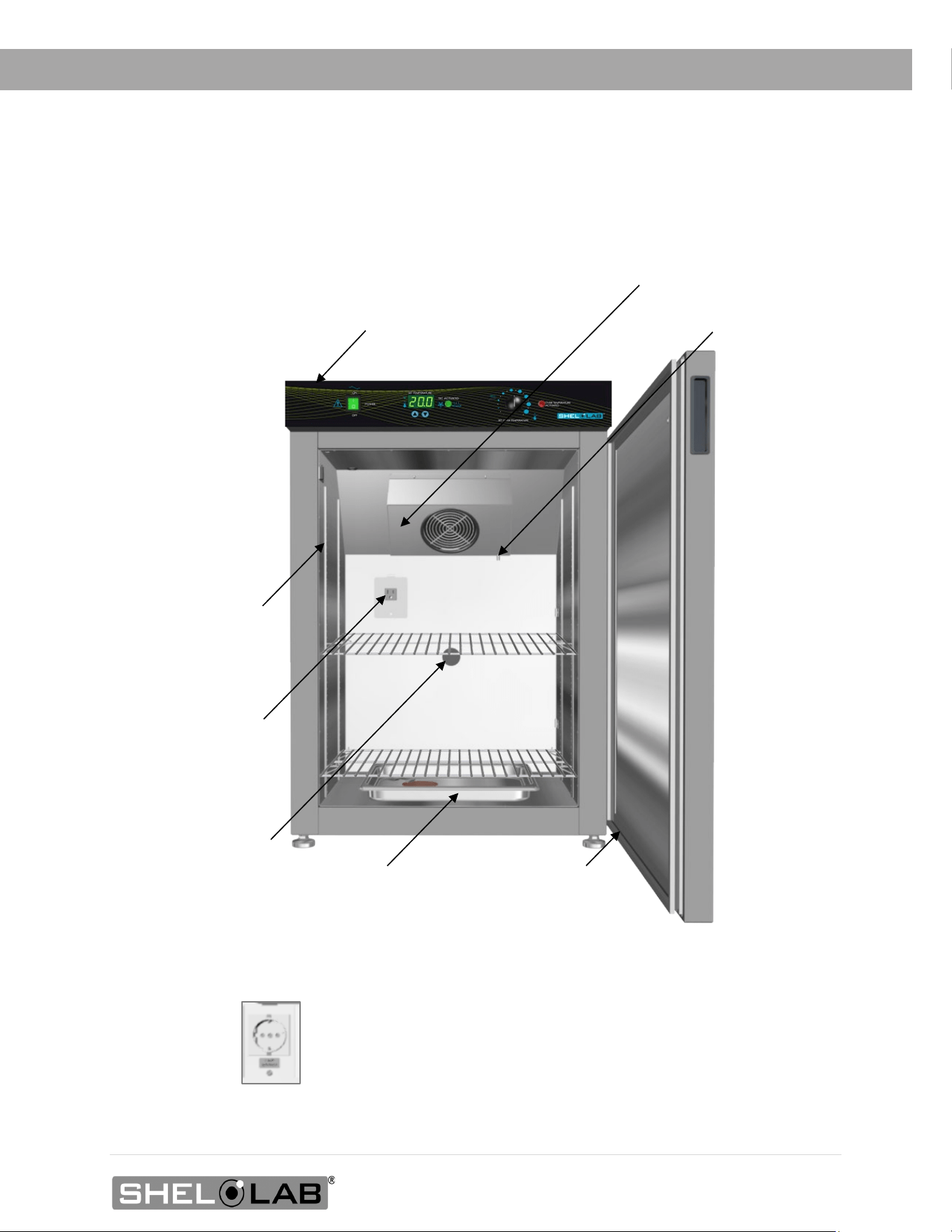
RECEIVING
Control Panel
Peltier Thermoelectric Heater – Chiller Housing
SRI3P
Door Gasket
Drain Port - TEC Housing
Access Port
Shelf Standard Rail
Chamber Door
SRI3P Chamber Power
Outlet, NEMA 5-15R
100 – 120 Volt*
Humidification Pan
*SRI3P-2 Chamber Power Outlet, CEE7/3 220 – 240
Volt
18 | Page
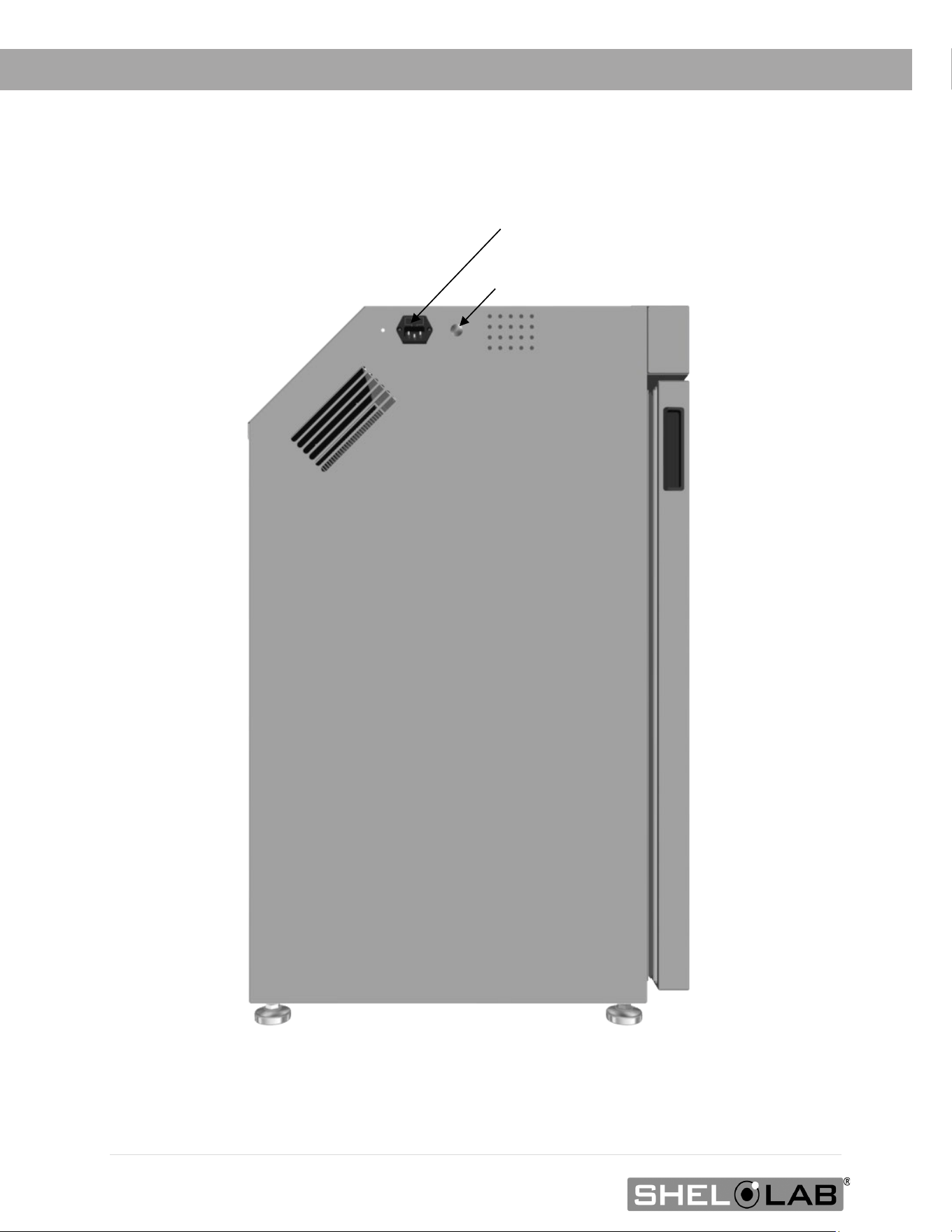
RECEIVING
SRI3P, Left Side of Unit
Power Cord Inlet with Fuse
Second Fuse Holder (220V Incubators only)

19 | Page
RECEIVING
RECORDING DATA PLATE INFORMATION
Record the unit model number, serial number, and part number below for future reference.
Customer Support needs this information to provide accurate help during support calls and emails.
• SRI6P, SRI20P: The data plate is located on the back of the unit, above the power inlet.
• SRI3Ps: The data plate is located on the left side of the unit, next to the power inlet.
MODEL NO:
SERIAL NO:
PART NO:

20 | Page
RECEIVING

21 | Page
INSTALLATION
INSTALLATION PROCEDURE CHECKLIST
Carry out the procedures and steps listed below to install the incubator in a new workspace
location and prepare it for use. All procedures are found in the Installation section of this manual.
Pre-Installation
Check that the required ambient condition for the unit are met, page 22
Check that the spacing clearance requirements are met, page 23
• Unit dimensions may be found on page 49
Check that a suitable electrical outlet and power supply is present, page 24
Install the Incubator in a suitable workspace location
Review the lifting and handling instructions, page 26
Make sure the incubator is level, page 26
Install the incubator in its workspace location, page 26
Set up the Incubator for use
Clean and disinfect the unit and shelving (recommended), page 27
SRI20P only: Install the side air ducts inside the incubation chamber, page 28
Install the shelving, page 29 through 31
Verify the stopper has been installed in the access port, page 32

22 | Page
INSTALLATION
REQUIRED AMBIENT CONDITIONS
Ambient Temperature Ranges: These units are built for use indoors under climate-controlled
conditions of 15.0°C to 30.0°C (59.0°F to 86.0°F).
SRIP3
• In workspace temperatures of 15.0°C to 30.0°C (59.0°F to 86.0°F), the SRI3P incubators
can achieve an operational chamber temperature range of 15.0°C to 40.0°C.
SRI6P Ambient Impact on Cooling
• In workspace temperatures of 15.0°C to 27.0°C (59.0°F to 80.6°F) the SRI6P incubators
can achieve an operational chamber temperature range of 15.0°C to 40.0°C.
• Sustained workspace temperatures of 27.1°C to 30.0°C (80.7°F to 86°F) will gradually
raise the lowest achievable incubation chamber temperature. See page 55.
SRI20P Ambient Impact on Cooling
• In workspace temperatures of 15°C to 25.0°C (59°F to 77.0°F) the SRI20P incubators
can achieve an operational chamber temperature range of 15.0°C to 40.0°C.
• Sustained workspace temperatures of 25.1°C to 30°C (77.1°F to 86.0°F) will gradually
raise the lowest achievable incubation chamber temperature. See page 55.
The following ambient conditions will affect the unit temperature performance.
• Ambient Temperature Variation: The workspace temperature should not change by
2°C (3.6°F) or more during operation.
• Maximum Humidity: No greater than 80% Relative Humidity (at 25°C / 77°F).
Air Quality: The units are rated to operate in a Pollution Degree 2 environment.
Maximum Altitude: 2000 meters (6562 feet).
Additional Environmental Factors: When selecting a location to install the unit, consider all
environmental conditions that can adversely impact its temperature performance. These include:
• Proximity to ovens, autoclaves, or any other device producing significant radiant heat.
• Heating and cooling vents or other sources of fast-moving air currents.
• High-traffic areas.
• Direct sunlight.
23 | Page
INSTALLATION
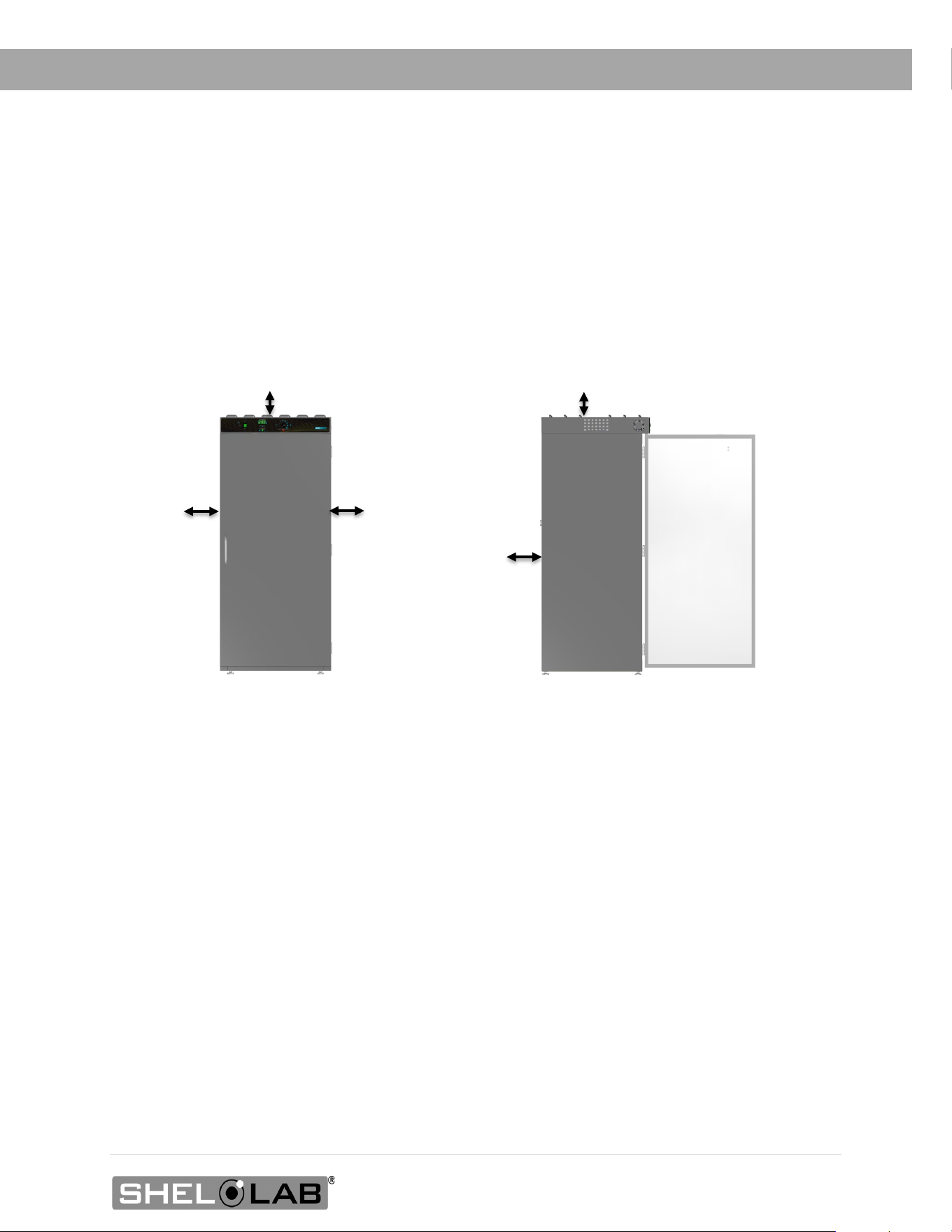
REQUIRED CLEARANCES
These clearances are required to provide airflows for ventilation and cooling.
4 inches (102 mm) of clearance is required on the sides and back.
2 inches (51 mm) of headspace clearance between the top of the unit and any overhead
partitions.
2” (51 mm)
Power Cord
2” (51
4” (102
4” (102
4” (102
Access Port
SRI3P: 24.5” (623 mm)
SRI6P 30.5” (775 mm)
SRI20P 30.5” (775 mm)
Door Swing
24 | Page
INSTALLATION
Note: See the next page for the -2, 220-volt incubators.
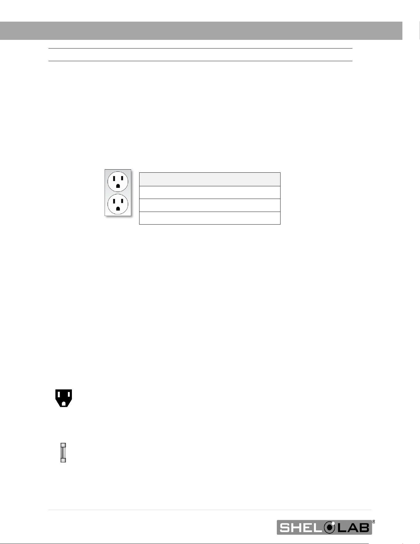
100 – 120 VOLT UNIT POWER REQUIREMENTS
Applies to: SRI3P, SRI6P, SRI20P
When selecting a location for the unit, verify each of the following requirements is satisfied.
Power Source: The power source for the unit must match the voltage and match or exceed the
ampere requirements listed on the unit data plate. These units are intended for 100 – 120V 50/60 Hz
applications at the following amperages:
Model Amperage
SRI3P 4.0 Amps
SRI6P
4.0 Amps
SRI20P
5.5 Amps
• The wall power source must be protective earth grounded.
• The unit may be damaged if the supplied voltage varies by more than 10% from
the data plate rating.
o The unit is safety-rated to withstand transient overvoltage levels up to Overvoltage
Category II.
• Use a separate circuit to prevent loss of the unit due to overloading or circuit failure.
• The recommended wall circuit breakers for these units are 15 amps.
• The wall power source must conform to all national and local electrical codes.
Power Cord: The unit must be positioned so that all end-users can quickly unplug the cord in the
event of an emergency.
o Each unit is provided with a 125-volt, 15 amp, 9ft 5 in (2.86m) NEMA 5-15P
power cord. Always use this cord or an identical replacement.
Fuse: Each unit ships with a fuse installed in the power cord inlet.
o The fuse must be installed and intact for the unit to operate.
o Always find and fix the cause of a blown fuse prior to putting the unit back into
operation.
o Fuse type: 5X20MM T6.3A 250V
Standard
NEMA 5-15R
Outlet
25 | Page
INSTALLATION
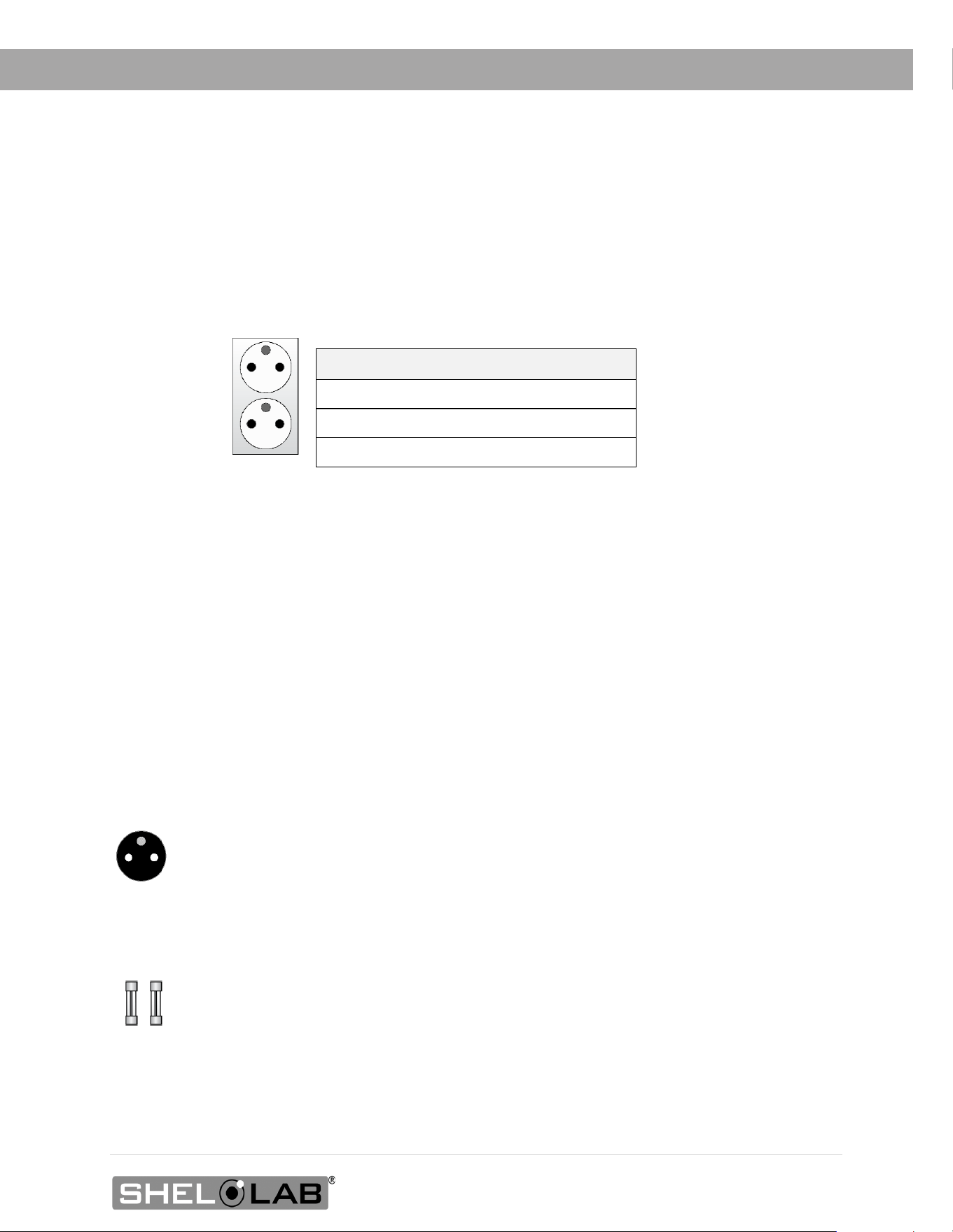
220 – 240 VOLT POWER SOURCE REQUIREMENTS
Applies to: SRI3P-2, SRI6P-2, SRI20P-2
When selecting a location for the unit, verify each of the following requirements is satisfied.
Power Source: The power source for the unit must match the voltage and match or exceed
the ampere requirements listed on the unit data plate. These units are intended for 220 –
240V 50/60 Hz applications at the following amperages:
Model Amperage
SRI3P-2 3.0 Amps
SRI6P-2
3.0 Amps
SRI20P-2
3.5 Amps
• The wall power source must be protective earth grounded.
• The unit may be damaged if the supplied voltage varies by more than 10% from
the data plate rating.
o The unit is safety-rated to withstand transient overvoltage levels up to Overvoltage
Category II.
• Use a separate circuit to prevent loss of the unit due to overloading or circuit failure.
• The recommended wall circuit breakers for these units are 20 amps.
• The wall power source must conform to all national and local electrical codes.
Power Cord: The unit must be positioned so that all end-users can quickly unplug the cord in the
event of an emergency.
o Each unit is provided with a 230-volt, 10 amp, EUR16P, 2.5 meters (8ft 2in),
CEE 7/7 power cord. Always use this cord or an identical replacement.
Fuses: Each unit ships with a fuse installed in the power cord inlet and a second fuse installed in
an adjacent fuse holder.
o Both fuses must be installed and intact for the unit to operate.
o Always find and fix the cause of a blown fuse prior to putting the unit back into
operation.
o Fuse type: 250V T6.3 amp, 5x20mm
CEE7 sockets
compatible with
CEE7/7 plugs
26 | Page
INSTALLATION
LIFTING AND HANDLING
The unit is heavy. Use appropriate lifting devices that are sufficiently rated for these loads. Follow these
guidelines when lifting the unit.
• Lift the unit only from its bottom surface.
• Doors, handles, and knobs are not adequate for lifting or stabilization.
• Restrain the unit completely while lifting or transporting so it cannot tip.
• Remove all moving parts, such as shelves and trays, and lock doors in the closed position
during transfers to prevent shifting and damage.
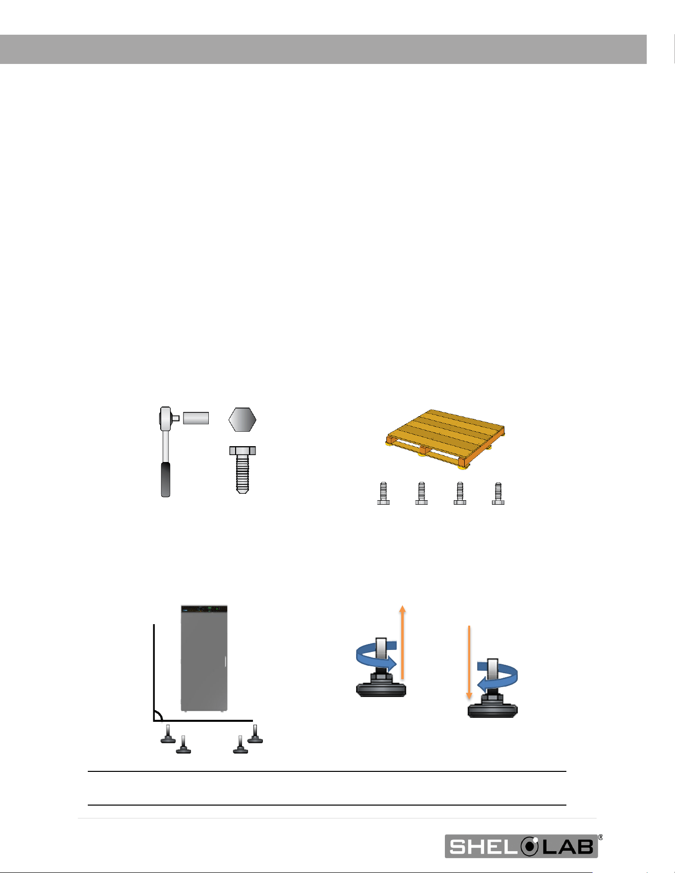
REMOVING FROM THE PALLET
The unit comes secured to a shipping pallet with ½” hex bolts inserted through the 4 leveling feet
holes on the bottom of the incubator. Use a socket wrench to remove the bolts and release the unit
from the pallet.
LEVELING
Install the 4 leveling feet in the 4 corner holes on the bottom of the unit. The unit must be level
and stable for safe operation and to ensure condensate drains properly from the heater – chiller
housing in the incubation chamber.
Note: T
o prevent damage when moving the unit, turn all 4 leveling feet so that the leg of each
foot sits inside the unit.
0.5 inch (12 mm)

27 | Page
INSTALLATION
INSTALL THE INCUBATOR
Install the unit in a workspace location that meets the criteria discussed in the previous entries of
the Installation chapter.
DEIONIZED AND DISTILLED WATER
Do not use deionized water to clean the unit, even if DI water is readily available in your
laboratory.
• The use of deionized water may corrode metal surfaces and voids the manufacturing
warranty.
• The manufacturer recommends the use of distilled water in the resistance range of 50K
Ohm/cm to 1M Ohm/cm, or a conductivity range of 20.0 uS/cm to 1.0 uS/cm, for cleaning
applications.
INSTALLATION CLEANING AND DISINFECTION
The manufacturer recommends cleaning the shelving and chamber before installing the shelving in
the chamber.
• The unit was cleaned at the factory but may have been exposed to contaminants during
shipping.
• Remove all wrappings and coverings from shelving prior to cleaning and installation. Do
not clean the shelving with deionized water.
• Please see the Cleaning and Disinfection procedure on page 47 in the User
Maintenance chapter for information on how to clean and disinfect without damaging the
unit.
28 | Page
INSTALLATION
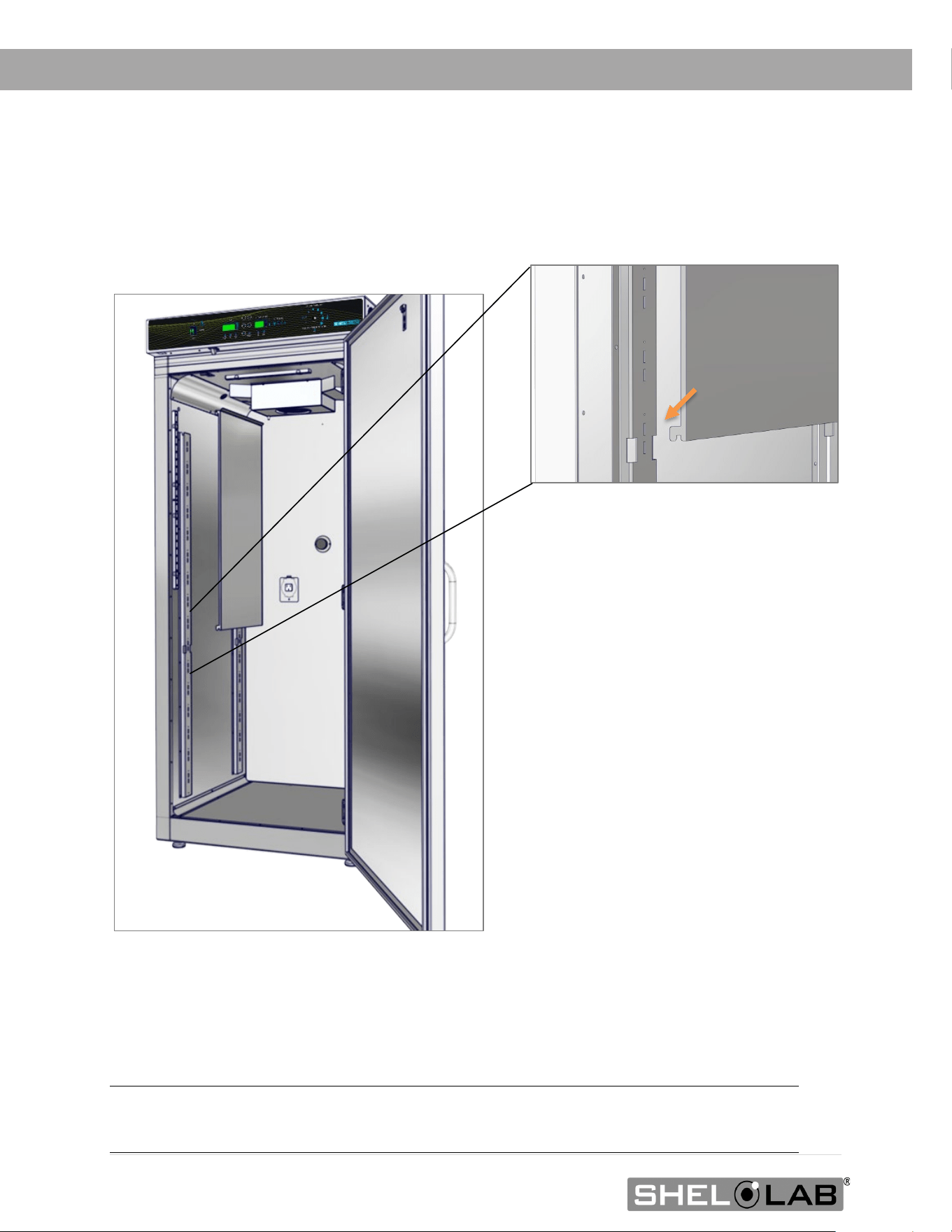
INSTALL THE SRI20P SIDE AIR DUCTS
Two air duct panels are packed with the accessories of the SRI20P incubators.
Installation
Insert the panel hooks, facing down, into the large notches in the shelf standard mounting rails.
SRI3P and SRI6P incubators do not use Side Air Ducts.
Note: The air duct panels play an important role in maintaining even air distribution inside the
SRI20P incubation chamber. Failure to install both air duct panels may adversely impact
temperature uniformity.
29 | Page
INSTALLATION
SHELVING INSTALLATION
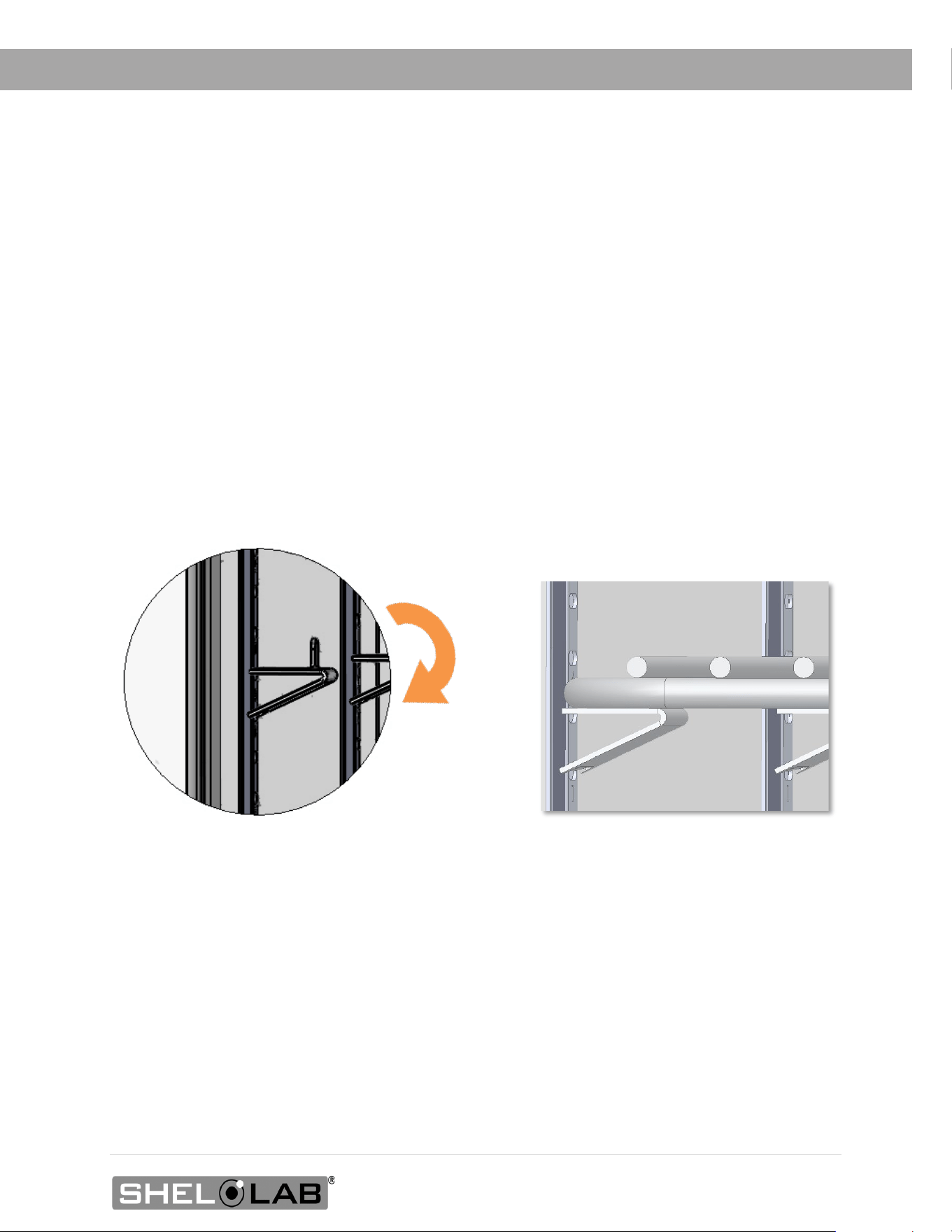
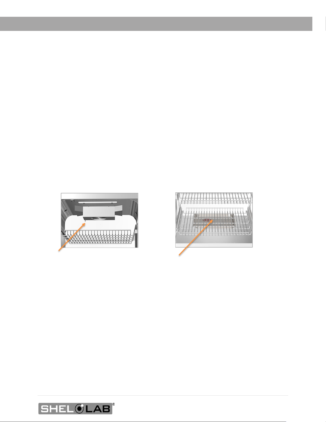
SRI3P Shelf Installation
Perform the following steps to install the wire basket shelves of the SRI3P incubator:
1. Install the shelf clips in the slots located on the shelf standards (mounting rails) of the
chamber interior, both front and back.
a. Squeeze each clip and hold.
b. Insert the top tab first, and then the bottom tab using a rocking motion.
2. Install 1 shelf on the 4 clips.
SRI3P Shelf Clip Installed SRI3P Shelf Installed
Rocking Motion
30 | Page
INSTALLATION
Shelving Installation Continued
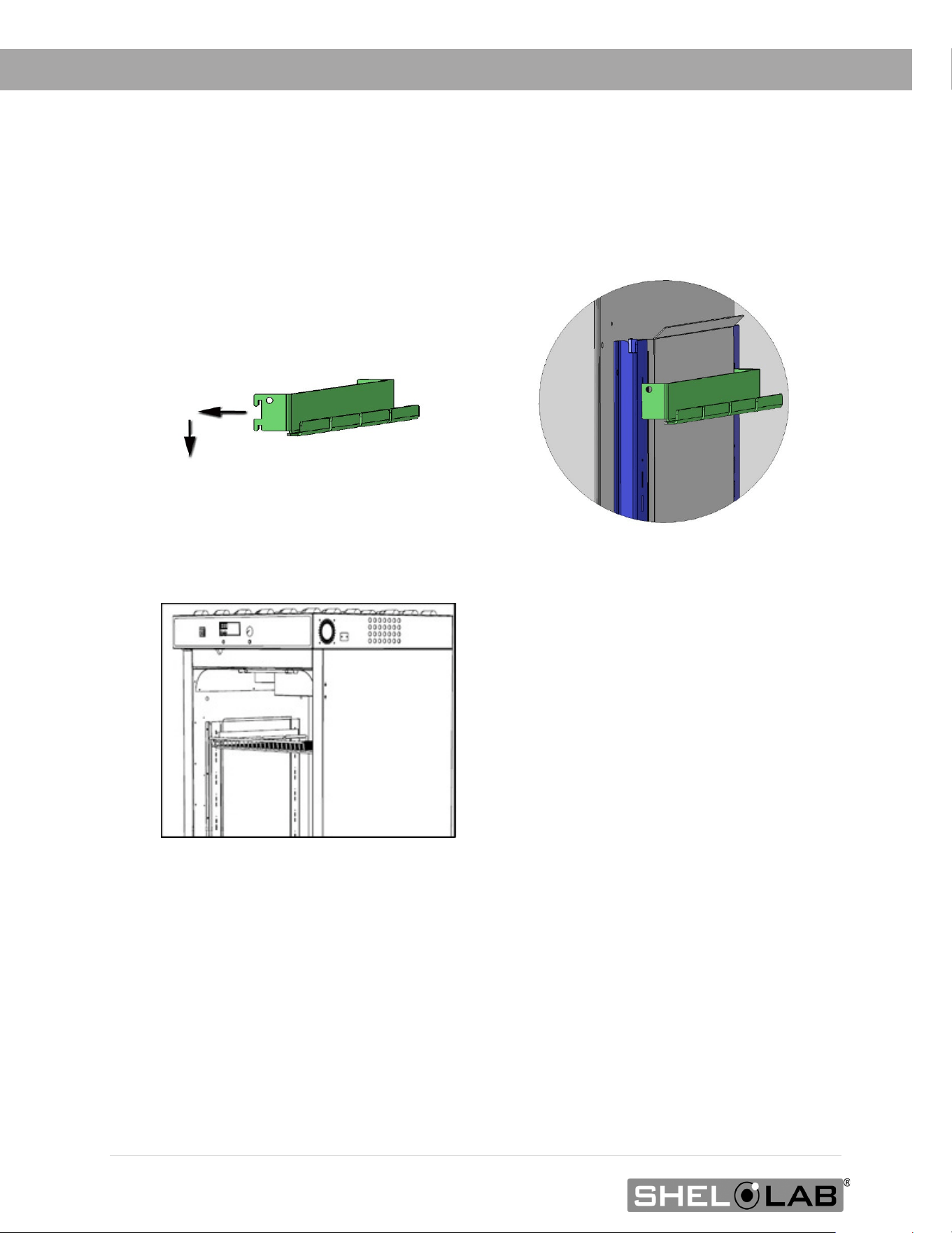
SRI6P and SRI20P Static Shelves
Remove all protective wrappings from shelves and shelving components prior to installation.
1. Insert the twin tabs on the bracket into slots in the shelf standard mounting rails located
on the sides of the incubation chamber.
2. Slide the bracket down so it sits securely attached to the shelf standard rails.
3. Repeat the process on the opposite side of the chamber with a second bracket.
4. Hang one shelf from the two installed brackets.
Shelf hung fr
om mounting bracket
Standard Shelf Bracket Installation
Standard Bracket Installed
31 | Page
INSTALLATION
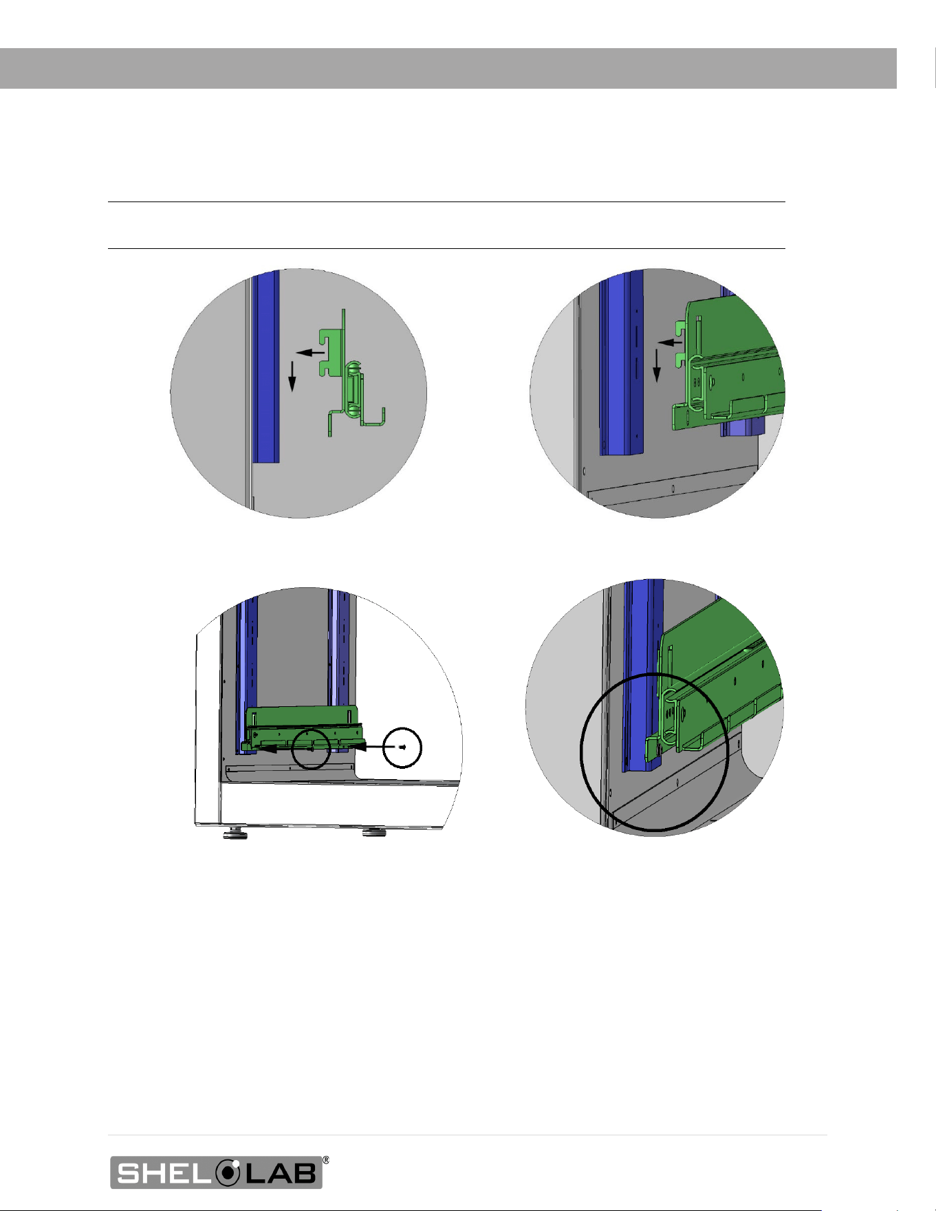
Sliding Shelf Installation SRI20P
Note: SRI6P do not come with sliding shelf b
rackets. Sliding brackets for SRI6P must be purchased
separately
1. Insert the sliding bracket’s twin tabs into the shelf standard mounting slots located on the
sides of the incubator chamber.
2. Slide the bracket down so it sits securely attached to the shelf standard mounting rails.
3. Insert and tighten two screws. The holes are located on the front and back of the bracket.
4. Repeat the process on the opposite side of the chamber for a second sliding bracket.
5. Hang one shelf from the two installed sliding brackets.
3.1. Insert the bracket screws
1. Insert the s
liding shelf mounting bracket tabs
2. Slide the bracket down
3.2 Tighten the screws.

32 | Page
INSTALLATION
ACCESS PORT STOPPER
Each incubator ships with a rubber stopper installed in the access port located
in the back of the incubation chamber.
• The stopper should always be installed inside the chamber to obtain
the best temperature uniformity and prevent condensation from forming
inside the port. Do not install on the outside of the port on the back of
the unit.
• Wires for thermocouples and other sensor probes may be introduced into
the chamber through the access port. The stopper may be put in place
over the wires.
33 | Page
GRAPHIC SYMBOLS
The unit is provided with multiple graphic symbols on its exterior. The symbols identify hazards and
the functions of the adjustable components, as well as important notes in the user manual.
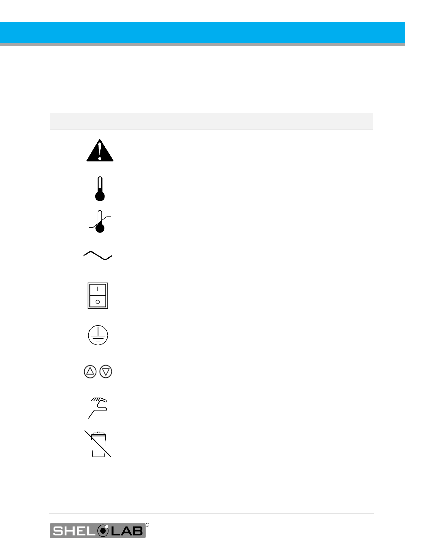
Symbol Definition
Consult the user manual.
Consulter le manuel d'utilisation
Temperature display
Indique l'affichage de la température
Over Temperature Limit system
Thermostat température limite contrôle haute
AC Power
Repère le courant alternatif
I/ON O/OFF
I indique que l'interrupteur est en position marche.
O indique que le commutateur est en position d'arrêt.
Protective earth ground
Terre électrique
Adjusts UP and DOWN
Ajuster la température de l'incubateur vers le haut et vers le bas
Manually adjustable
Indique un réglage manuel
Recycle the unit. Do not dispose of in a landfill.
Recycler l'unité. Ne jetez pas dans une décharge.

34 | Page
SYMBOLS
35 | Page
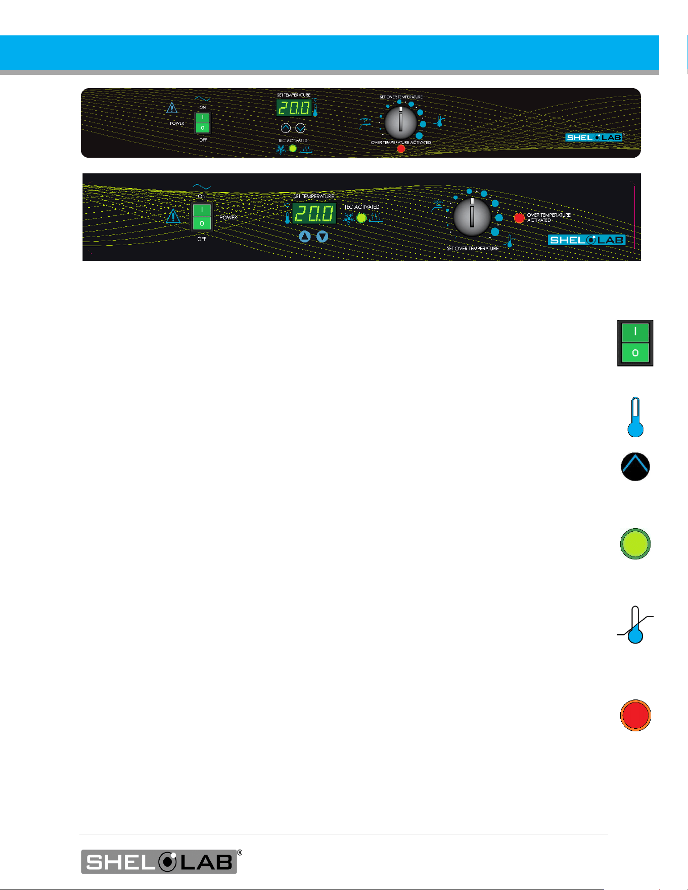
CONTROL PANEL OVERVIEW
Control Panel SRI6P SRI20P Top | SRI3P Bottom
Power Switch
Power is supplied and the switch illuminates when in the ( I ) ON position.
Set Temperature Display and Controls
Shows the current chamber temperature. The Up and Down arrow buttons are used to access the
Temperature Setpoint (SP) or Calibration Offset (C O) display modes and input the temperature
setpoint or calibration adjustment value and turn the door open alarm off or on.
Heating and Cooling Indicator Light
The green TEC ACTIVATED light illuminates whenever the Peltier TEC-H device is actively cooling
or heating the chamber. This light will illuminate frequently during normal operations.
Set Over Temperature
This graduated dial sets the mechanical heating cutoff point for the Over Temperature Limit
system. The system prevents unchecked heating of the chamber in the event of a hardware failure
or external heat spike. For more details, please see the Over Temperature Limit System
description in the Theory of Operations (page 41).
The red light illuminates when the Over Temperature system cuts power to the Peltier heating
circuits.

36 | Page
CONTROLS

37 | Page
OPERATION
THEORY OF OPERATION
SRIP incubators provide stable and uniform incubation environments suitable for biological oxygen
demand studies, including at or below standard room temperature.
Heating and Cooling
The incubator employs a solid-state thermoelectric cooling-and-heating (TEC-H) device, which
operates using the Peltier effect to supply heating or cooling as needed.
The Peltier effect: An electrical current between two touching but dissimilar conductor plates
produces a heat flow from one plate to the other. The flow direction can be flipped by reversing
the current direction. The sandwiched TEC-H conductors effectively operate as a reversible high-
efficiency heat pump. A fan attached to the TEC-H blows air cooled or heated by the chamber-side
Peltier plate into the chamber interior to achieve the current setpoint target temperature.
When powered, the incubator automatically heats or chills to and then maintains the operator-
selected temperature setpoint. The unit controller senses the chamber air temperature via a solid-
state probe located in the unit interior. When the unit controller detects a temperature deviation
from the target setpoint, it pulses power to the Peltier thermoelectric cooling and heating (TEC-H)
device.
The unit controller uses Proportional – Integral – Derivative (PID) algorithms to avoid significantly
overshooting the setpoint. This means the rate of heating or cooling slows as the temperature
approaches the target temperature.
Additionally, the PID loops optimize heating and cooling rates for the temperature environment around
the incubator. If the incubator is operating in a cool room, it will increase the length of heating pulses to
compensate. Likewise, when operating in a warm room the unit uses shorter pulses to heat. If the
ambient temperature conditions are significantly changed, there may be minor over or undershoots as
the unit adapts.

38 | Page
OPERATION
Door Alarm
The incubator is equipped with a magnetic induction door alarm, which activates when the door is
open for 60 seconds. When the alarm is active, an audio alert will sound, and the temperature
display will flash. Closing the door will temporarily turn off the alarm. The alarm may be turned off
indefinitely using the Door Alarm Setting procedure on page 4545
The Over Temperature Limit System
The mechanical OTL heating cutoff system monitors the chamber temperature using an
independent hydrostatic temperature probe located in the chamber air stream. If the chamber
temperature is higher than the OTL setting, the system prevents power from flowing to the Peltier
TEC-H device in the direction that adds heat to the chamber. In other words, the Peltier device will
not heat while the OTL system is active, but it should continue to cool the chamber.
The OTL heating cutoff limit is set by the end-user, normally at approximately 1°C above the
application temperature. It is intended to help safeguard samples and prevent runaway heating in
the event of a hardware failure or a heat spike generated inside or outside of the incubator
chamber.
The OTL cutoff cannot prevent a rise in heat caused by a complete failure of the Peltier TEC-H
itself. With the loss of the chilling function, the chamber temperature will rise to the ambient room
temperature, plus 1 or 2°C.

39 | Page
OPERATION
PUT THE INCUBATOR INTO OPERATION
Carry out the following steps and procedures to put the unit into operation after installing it in a
new workspace environment.
1. Plug in the power cord
Attach the power cord that came with the unit to the
power inlet receptacle on the back of the incubator.
Plug the power cord into the workspace electrical outlet.
2. Turn on the incubator
Place the incubator Power Switch in the ON ( I ) position.
• The switch illuminates
• The Temperature display illuminates
3.
Set the Temperature Setpoint
See the Set the Temperature Setpoint procedure
on page 40.
4. Allow the incubator to heat soak for a minimum of 8 hours
Run the unit for at least 8 hours (for example, overnight) with
chamber door closed prior to:
• Setting the Over Temperature Limit (next step).
• Loading samples.
5. Set the Over Temperature Limit
Set the Over Temperature Limit. See page 41.
• The incubator must be heated and stable at your
application temperature prior to performing this
procedure.
The incubator is now ready for use.
• You may Load Samples, see page 55
40 | Page
OPERATION
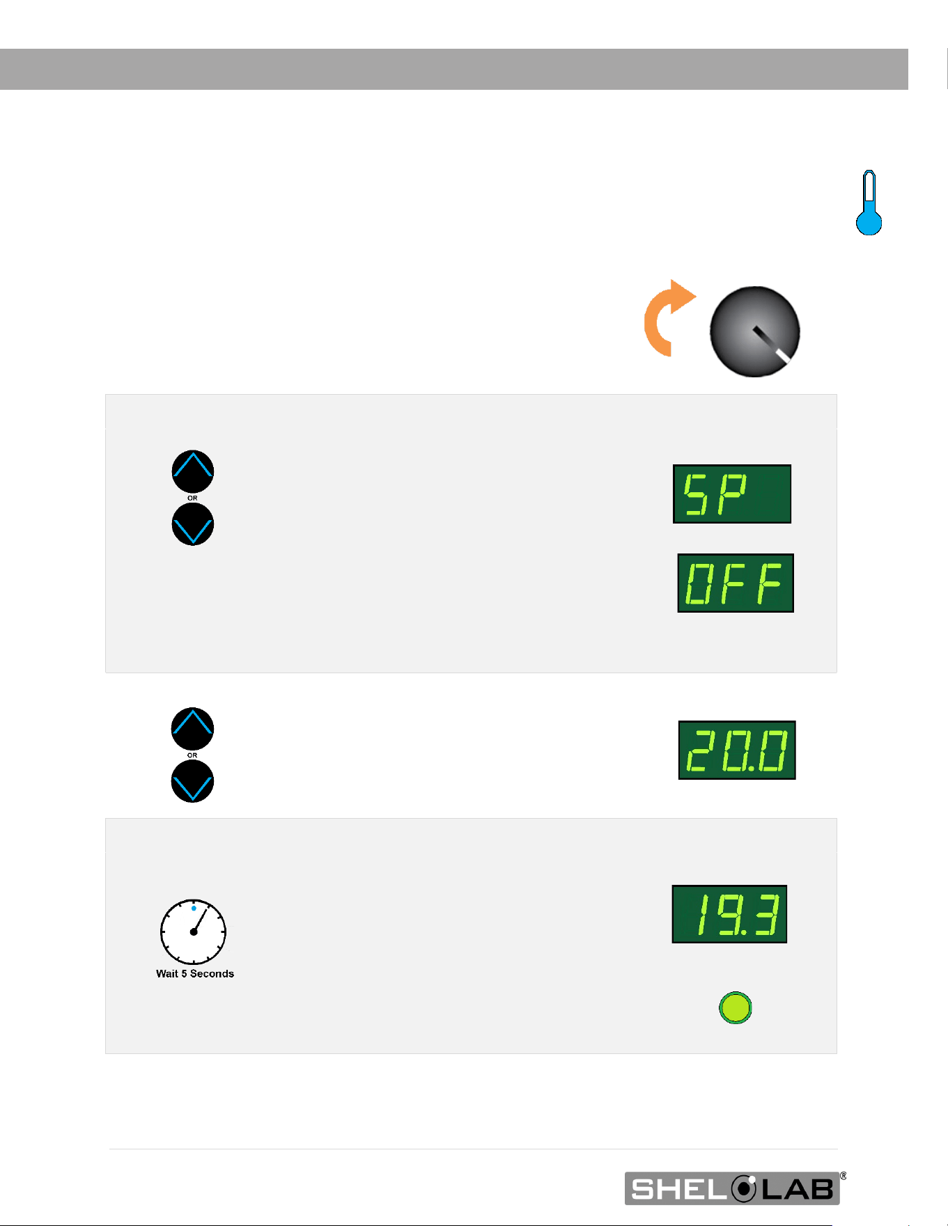
SET THE TEMPERATURE SETPOINT
Perform the steps below to adjust the setpoint to your process or application temperature.
End of Procedure
1. Set the OTL control to its maximum setting, if not already set to max
• This prevents the heating cutoff system
from interfering with this procedure.
2. Put the incubator in Temperature Setpoint adjustment mode.
Press and hold either the Up or Down
arrow buttons to activate the temperature
setpoint adjustment mode.
• The display will briefly flash the
letters “SP”, then show the flashing,
adjustable temperature setpoint.
Note: The display will automatically exit the adjustment
mode after 5 seconds of inactivity, with the last shown
setpoint value saved.
Setpoint Adjustment Mode
Initial Setpoint
3. Set the Temperature Setpoint.
Use the Up and Down arrow buttons to
change the temperature setpoint.
New Setpoint
4. Wait 5 seconds after entering the Setpoint.
• The display will stop flashing, and the
setpoint is now saved in the controller.
• The unit will now automatically heat
or chill to match your setpoint.
• The display will revert to showing
the current chamber temperature.
Heating to the Setpoint
41 | Page
OPERATION
Note: Test the OTL system at least once per year to verify its functionality. Failure to set the
OTL voids the manufacturing defect warranty if over temperature damage occurs.
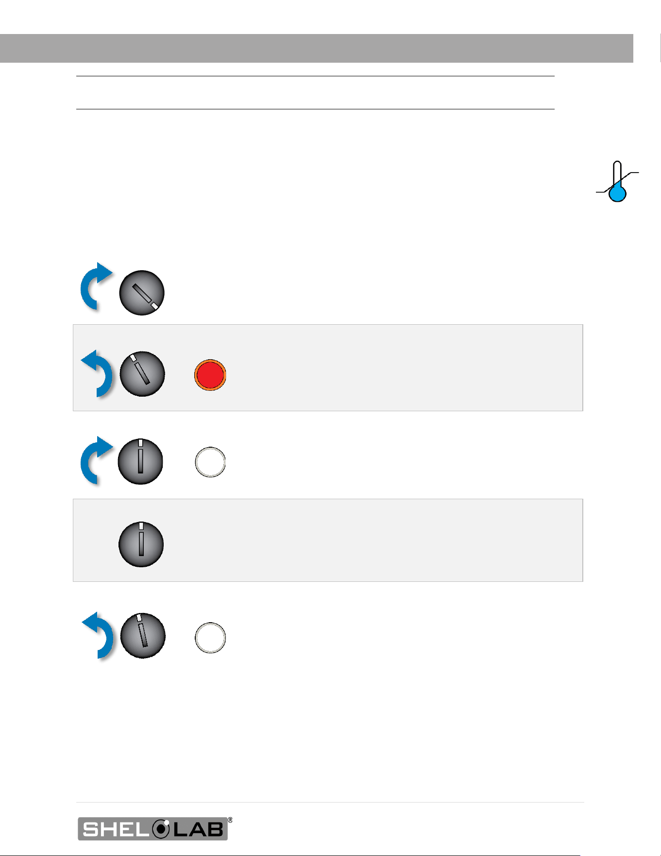
SET THE OVER TEMPERATURE LIMIT (OTL)
This procedure sets the mechanical heating cutoff to approximately 1˚C above the current chamber
temperature. Perform this procedure when the unit has been running with no temperature
fluctuations at your application temperature for at least 8 hours.
If the OTL sporadically activates after setting the control, turn the dial very slightly to the right
(clockwise).
If the OTL continues activating, check for ambient sources of heat or cold that may be adversely
impacting the unit temperature stability. If you find no sources of external or internal temperature
fluctuations, contact Customer Support or your distributor for assistance.
1. Set the OTL control to its maximum setting, if not already set to max.
2. Turn the dial counterclockwise (to the left) until the OTL light illuminates
3. Slowly turn the dial clockwise (to the right) until the OTL light turns off
• The Over Temperature Limit is now set at approximately
1˚C above the current chamber temperature.
4. Leave the OTL dial set just above the activation point
Optional: Turn the dial slightly to the left (counterclockwise)
•
This sets the OTL cutoff threshold nearer to the current
chamber temperature.

42 | Page
OPERATION
LOADING SAMPLES
The manufacturer strongly recommends waiting at least 8 hours after putting the unit into
operation before loading samples in the incubation chamber. This allows the unit to heat soak,
protecting against temperature instability.
• Samples should be placed at least 1 inch (25 mm) away from the chamber walls.
• Proper spacing allows for maximum air circulation and a higher degree of temperature
uniformity.
• Proper spacing also decreases the chance of condensate forming in the incubator when
operating with a large number of samples in the chamber.
CHAMBER POWER OUTLET
Each incubator comes with a 1-amp power outlet inside the chamber. Do not attach
powered equipment that draws more than 1 amp.
• The SRI3P, SRI6P, and SRI20P power outlet provides 100 – 120 volts.
• The SRI3P-2, SRI6P-2, and SRI20P-2 power outlet provides 220 – 240 volts.
Verify that any powered accessory equipment used inside the chamber can safely and
effectively operate within your selected temperature range.
Powered equipment, such as stirrers or shakers, can generate heat sufficient to disrupt the
thermal uniformity and stability of the chamber.
43 | Page
OPERATION
HUMIDIFYING THE INCUBATOR
Closed bottle BOD applications do not require humidification.
Breathable Sample Containers: Placing a small number of open or breathable media containers
in the incubator chamber may lead to excessive drying of sample media. Unusually dry
environmental conditions may also contribute to sample drying.
Humidification Kit: SRIP incubators are supplied with a humidity collection pan and tubing
accessory kit: The kit redirects moisture that normally condenses on the heat sink fins of the Peltier
TEC-H device and uses it to humidify the incubator.
The humidification kit is intended for use while running small loads.
1. Remove the Peltier drain cover.
2. Connect the kit tubing to the port.
3. Run the tubing down behind the
shelves.
4. Place humidification pan on chamber
floor.
5. Place the other end of the tubing in the
pan.

44 | Page
OPERATION
CONDENSATION AND THE DEW POINT
Relative humidity inside the incubation chamber should never be allowed to exceed
80% at 25°C. Exceeding this threshold will likely result in condensation and leaks around the
incubator and may cause corrosion damage if allowed to continue for any significant length of time.
Condensation takes place whenever the humidity level in the incubation chamber reaches the dew
point. The dew point is the level of humidity at which the air cannot hold more water vapor. The
warmer the air, the more water vapor it can hold.
As the level of humidity rises in an incubation chamber, condensate will first appear on surfaces
that are cooler than the air temperature. Near the dew point, condensate forms on any item or
exposed surface even slightly cooler than the air. When the dew point is reached, condensate
forms on nearly all exposed surfaces.
Managing condensation primarily depends on either lowering the humidity level or increasing the
air temperature in the incubator chamber.
Note: Rising or falling air pressure from the weather will adjust the dew point up and down in small
increments. If the relative humidity in the incubation chamber is already near the dew point,
barometric fluctuations may push it across the dew threshold.
Note: T
hin air at higher altitudes holds less humidity than the denser air found at or near sea level.
If excessive condensate has appeared in the incubation chamber, dry the chamber interior.
After removing the condensate, check the following.
• Ensure samples on the shelves are evenly spaced to allow for good airflow.
• Ensure the chamber door is closing and latching properly.
• Verify the chamber access port is closed. The black, rubber port stopper that came with
the unit should be installed on the inside of the incubator in the chamber.
• Are frequent or lengthy chamber door openings causing significant temperature disruptions
and chilling the chamber surfaces? If so, reduce the number of openings.
• Are there too many open or “breathable” containers of evaporating sample media in the
chamber? If so, reduce the number of open sample containers.
• Does the ambient humidity in the room exceed the stated operating range of 80% relative
environmental humidity? If so, lower the room humidity.
• Is the incubator exposed to an external flow of cold air such as an air-conditioning vent or
a door to a cooler hallway or adjacent room? Block or divert the air or reposition the unit.
• Check the door gasket for damage, wear, or signs of brittleness or dryness. Arrange for
replacement of the gasket if damaged or excessively worn.
45 | Page
OPERATION
Note: Changing the Door Alarm setting accesses the Temperature Setpoint menu but does not
adjust the temperature setpoint.
DOOR ALARM SETTING
The incubator comes with a Door Alarm that sounds an audible alarm and causes the temperature
display to blink on and off when the door has been open for longer than 60 seconds. The alarm
comes from the factory set to On.
Turning the Alarm Off
Turning the Alarm On
• Follow the steps above to access the Temperature Setpoint
adjustment mode.
• For Step 2, press and hold the Up button until the display
reads “dI” to change the Door Alarm setting to On.
End of Procedure
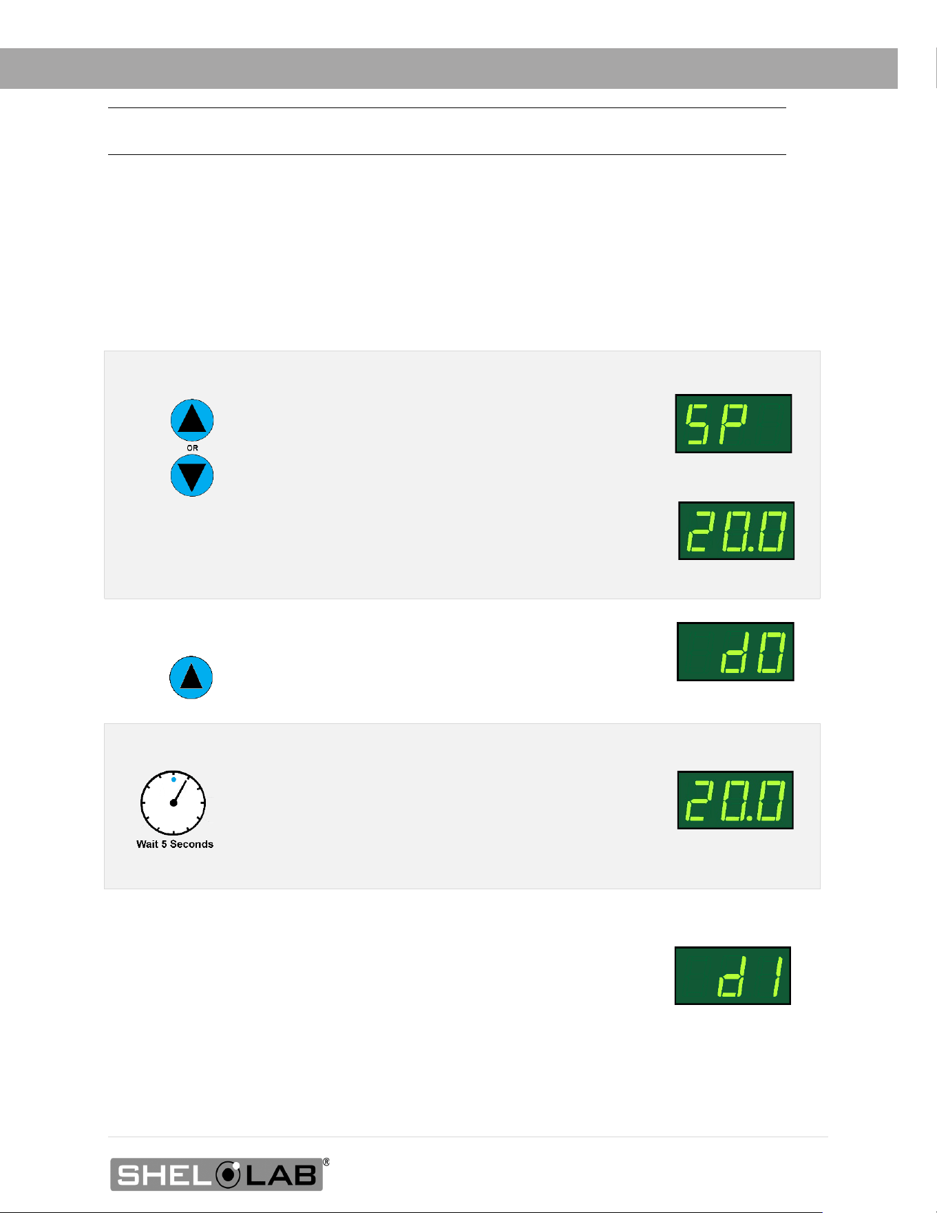
1. Put the incubator in Temperature Setpoint adjustment mode.
Press and hold either the Up or Down arrow
buttons to activate the temperature setpoint
adjustment mode.
• The display will briefly flash the letters “SP”, then
show the flashing, adjustable temperature setpoint.
Note: The display will automatically exit the adjustment mode
after 5 seconds of inactivity without saving any changes.
Setpoint Adjustment
Mode
Temperature Setpoint
2. Change the Door Alarm setting to Door Off.
Press and hold the Up button until the display reads
“dO”. This indicates the Door Alarm has been set to Off.
Door Alarm Off
3. Wait 5 seconds after changing the Door Alarm setting.
• The display will revert to showing the current
chamber air temperature.
The door alarm is now set to Off. The temperature
setpoint has not been changed.
Temperature Setpoint
Door Alarm On

46 | Page
OPERATION

47 | Page
USER MAINTENANCE
Warning: Disconnect this unit from its power supply prior to performing maintenance or services.
Avertissement: Débranchez cet appareil de son alimentation électrique avant d'effectuer la
maintenance ou les services.
CLEANING AND DISINFECTING
If a hazardous material or substance has spilled in the unit chamber, immediately initiate your site
Hazardous Material Spill Containment protocol. Contact your local Site Safety Officer and follow
instructions per the site policy and procedures.
• Periodic cleaning and disinfection are required.
• Do not use spray on cleaners or disinfectants. These can leak through openings and coat
electrical components.
• Consult with the manufacturer or their agent if you have any doubts about the
compatibility of decontamination or cleaning agents with the parts of the equipment or
with the material contained in it.
• Do not use cleaners or disinfectants that contain solvents capable of harming paint
coatings or stainless steel surfaces. Do not use chlorine-based bleaches or
abrasives; these will damage the chamber liner.
Warning: Exercise caution if cleaning the unit with alcohol or flammable cleaners. Always allow the
unit to cool down to room temperature prior to cleaning and make sure all cleaning agents have
evaporated or otherwise been completely removed prior to putting the unit back into service.
Avertissement: Soyez prudent lorsque vous nettoyez l'appareil avec de l'alcool ou des produits de
nettoyage inflammables. Laissez toujours refroidir l'appareil à la température ambiante avant le
nettoyage et assurez-vous que tous les produits de nettoyage se sont évaporés ou ont été
complètement enlevés avant de remettre l'appareil en service.
Cleaning
1. Disconnect the unit from its power supply.
2. Remove all removable interior components such as shelving and accessories.
3. Clean the unit with a mild soap and water solution, including all corners.
o Do not use an abrasive cleaner, these will damage metal surfaces.
o Do not use deionized water to rinse or clean with.
o Take special care when cleaning around the temperature sensor probes in the
chamber to prevent damage. Do not clean the probes.
4. Rinse with distilled water and wipe dry with a soft cloth.

48 | Page
MAINTENANCE
Disinfecting
For maximum effectiveness, disinfection procedures are typically performed after cleaning. Keep
the following points in mind when disinfecting the unit.
• Turn off and disconnect the unit to safeguard against electrical hazards.
• Disinfect the unit chamber using commercially available disinfectants that are non-
corrosive, non-abrasive, and suitable for use on stainless steel and glass surfaces. Contact
your local Site Safety Officer for detailed information on which disinfectants are compatible
with your applications.
• If permitted by your protocol, remove all removable interior accessories (shelving and
other non-attached items) from the chamber when disinfecting.
• Disinfect all surfaces in the chamber, making sure to thoroughly disinfect the corners.
Exercise care to avoid damaging the sensor probes.
When disinfecting external surfaces, use disinfectants that will not damage painted metal, glass, and
plastic.
DOOR COMPONENTS
Periodically, inspect the door latch, trim, catch, and gaskets for signs of deterioration. Failure to
maintain the integrity of the door system shortens the life span of the incubator.
ELECTRICAL COMPONENTS
Electrical components do not require maintenance. If the incubator fails to operate as specified,
please contact your distributor or Technical Support for assistance.
49 | Page
MAINTENANCE
CALIBRATE THE TEMPERATURE DISPLAY
Note: Performing a temperature display calibration requires a temperature reference device. Please
see the Reference Sensor Device entry on page 12 for the device requirements.
Temperature calibrations are performed to match the incubator temperature display to the actual
air temperature inside the incubation chamber. The actual air temperature is supplied by a
calibrated reference device. Calibrations compensate for long-term drifts in the incubator
microprocessor controller as well as those caused by the natural material evolution of the sensor
probe in the heated incubator space. Calibrate as often as required by your laboratory or
production protocol, or regulatory compliance schedule. Always calibrate to the standards and use
the calibration setup required by your industry requirements or laboratory protocol.
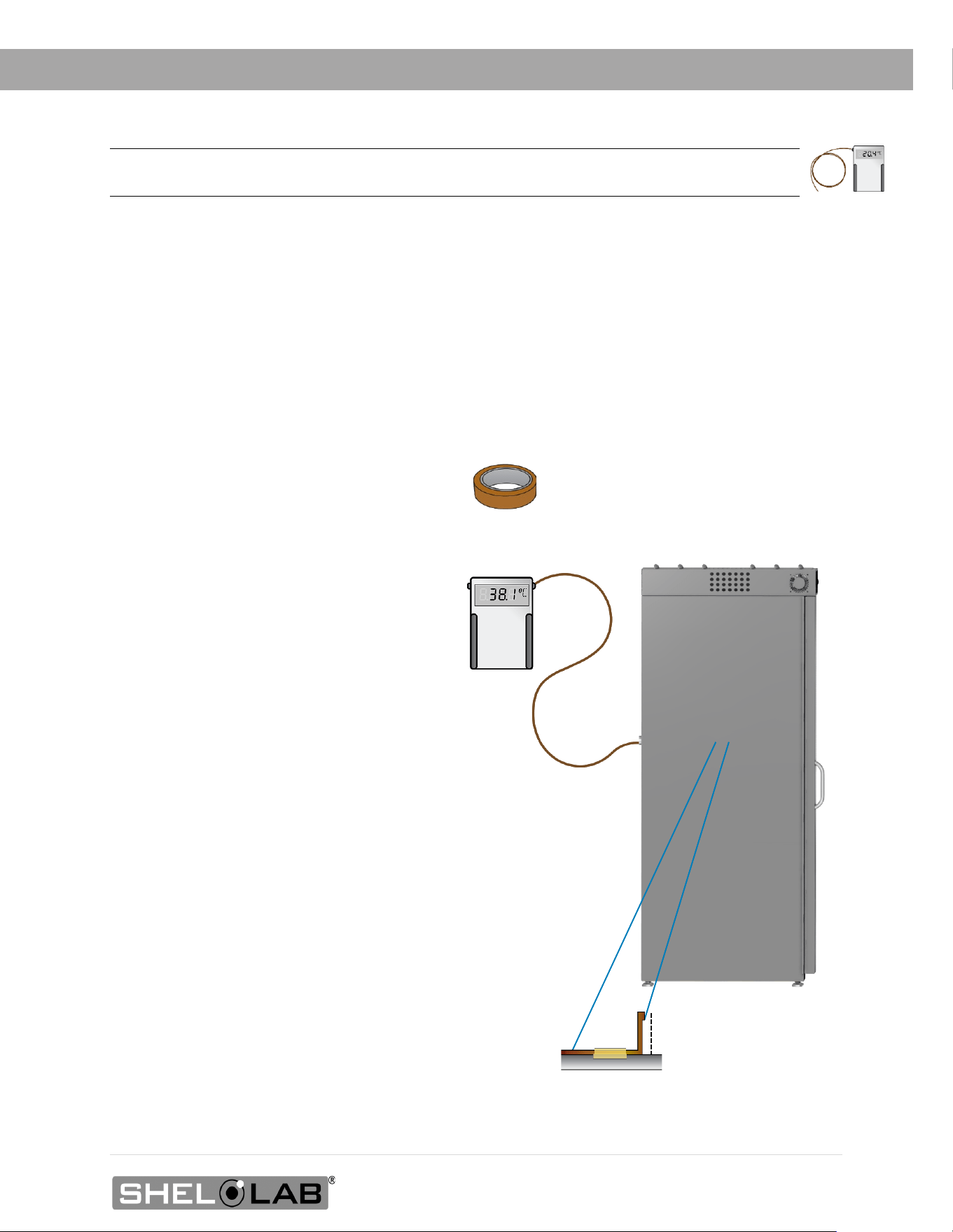
A suggested calibration setup
2” (51
mm)
1. Introduce the reference device
thermocouple sensor probe through the
access port on the back of the incubator into
the incubation chamber.
2. Position the sensor probe head as close
as possible to the geometeric center point of
the chamber.incubation chamber with the
probe heads at least 2 inches (51 mm)
above the shelving to avoid heatsinking.
Secure all probes in place with non-stick,
heat-resistant tape.
3. After securing the probe in position,
carefully place the access port stopper in
the port over the probe wire. Use non-
stick tape to seal any gaps created
between the stopper and the port by the
probe
4. The incubation chamber door must
be closed and latched. Failure to do so
will prevent an accurate calibration.
Use non-marking, heat-resistant polyamide tape
to hold the thermocouple probe in place. The
manufacturer recommends Kapton brand tape,
0.5 inches width (12 mm), 2 mil thickness.
50 | Page
Begin Calibration
MAINTENANCE
5. Allow the chamber air temperature to stabilize before calibrating.
• The incubator cannot be accurately calibrated before stability is achieved.
• When first putting the incubator into operation in a new location, it must run heating or
chilling for at least 8-hours to stabilize.
• The temperature is considered stabilized when the incubator has operated at your
calibration temperature for at least 1 hour with no fluctuations greater than the specified
temperature stability of the unit (see page 55)
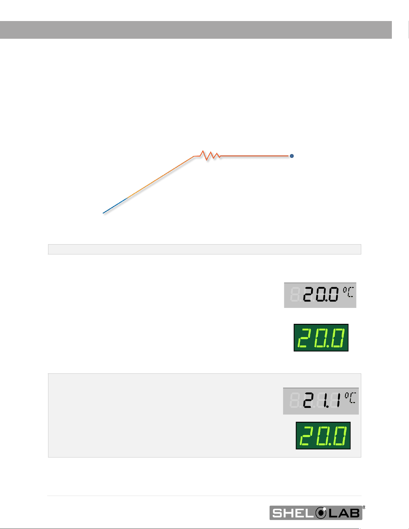
Suggested Temperature Calibration
1
Once the incubator temperature has stabilized, compare the
reference device and incubator temperature display readings.
• If the readings are the same, or the difference between
the two falls within the acceptable range of your protocol,
the display is accurately showing the incubator air
temperature. The Temperature Calibration
procedure is now complete.
- Or -
• If a difference falls outside of your protocol range,
advance to step 2.
Reference Device
Set Temperature
2
A display calibration adjustment must be entered to match the
display to the reference device. See next step.
Reference Device
X
8 Hours
Start
Fluctuations
(Exaggerated)
Required Stability
Period
Required temperature stability period operating undisturbed.
51 | Page
MAINTENANCE
Temperature Calibration Continued
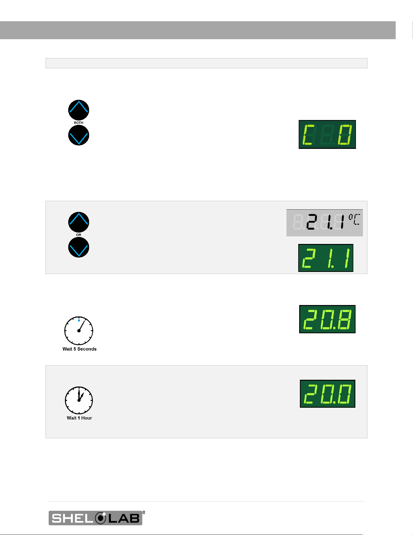
3
Place the display in its temperature calibration mode.
a. Press and hold both the UP and DOWN
temperature arrow buttons simultaneously for
approximately 5 seconds.
b. Release the buttons when the temperature display
shows the letters “C O”. The display will begin
flashing the current temperature display value.
Note: If an arrow key is not pressed for five seconds, the
display will cease flashing, and store the last displayed
number as the new current chamber temperature value.
4
Use the Up or Down arrows to adjust the current
display temperature value until it matches the
reference device temperature reading.
Reference Device
5
After matching the display to the reference device, wait 5
seconds.
• The temperature display will cease flashing and
store the corrected chamber display value.
• The incubator will now begin heating or chilling
to reach the setpoint with the corrected display
value.
Cooling to Setpoint
6
After the incubator has achieved the corrected
temperature, allow the chamber to sit at least one 1 hour
undisturbed to stabilize.
• Failure to wait until the incubator is fully
stabilized will result in an inaccurate reading.
Setpoint Achieved

52 | Page
MAINTENANCE
End of procedure
Temperature Calibration Continued
7
Compare the reference device reading with the chamber
temperature display again.
• If the reference device and the chamber temperature
display readings are the same or the difference falls
within the range of your protocol, the incubator is
now calibrated for temperature.
- OR -
• See the next step if the readings fail to match or fall
outside of your protocol range.
Reference Device
8
If the two readings are not the same, and the difference still
falls outside the acceptable range of your protocol, repeat
steps 3 – 7 up to two more times.
Three calibration attempts may be required to successfully
calibrate units that are more than ±2°C out of calibration.
Reference Device
X
9
If the temperature readings of the incubator temperature display and the reference
device still fall outside your protocol after three calibration attempts, contact your
incubator distributor or Customer Support for assistance.
53 | Page
UNIT SPECIFICATIONS
SRI3P, SRI6P, and SRI20P units are 110 – 120 voltage units. SRI3P-2, SRI6P-2, and SRI20P-2 units
are 220 – 240 voltage units. Please refer to the unit data plate for individual electrical
specifications.
Technical data specified applies to units with standard equipment at an ambient temperature of
25°C and at nominal voltage. The temperatures specified are determined in accordance to factory
standard following DIN 12880 respecting the recommended wall clearances of 10% of the height,
width, and depth of the inner chamber. All indications are average values, typical for units
produced in the series. We reserve the right to alter technical specifications at all times.
WEIGHT
Model Shipping Net Weight
SRI3P 135 lbs. / 61 kg 105.0 lbs / 47.6 kg
SRI6P 205 lbs. / 93 kg 125.0 lbs / 56.7 kg
SRI20P 405 lbs. / 184 kg 246.0lbs / 111.6 kg
DIMENSIONS
In inches
Model Exterior W × D × H Interior W × D × H
SRI3P 24.1 x 21.3 x 33.8 in 18.9 x 16.9 x 26.4 in
SRI6P 30.0 x 31.5 x 33.5 in 25.5 x 24.0 x 18.5 in
SRI20P
30.0 x 31.5 x 69.5 in
25.5 x 24.0 x 54.5 in
In Millimeters
Model Exterior W × D × H Interior W × D × H
SRI3P
612 x 541 x 859 mm
480 x 429 x 670 mm
SRI6P 762 x 800 x 851 mm 648 x 610 x 470 mm
SRI20P 762 x 800 x 1766 mm 648 x 610 x 1384 mm
CAPACITY
Model Cubic Feet Liters
SRI3Ps
3.5
99.0
SRI6P
6.5 185.5
SRI20P 19.3 546.6
54 | Page
UNIT SPECIFICATIONS
SHELF CAPACITY BY WEIGHT
Model Per Shelf* Total**
SRI3P 35.0 lbs / 15.9 kg 70.0 lbs / 31.7 kg
SRI6P 75.0 lbs / 34.0 kg 150.0 lbs / 68.0 kg
SRI20P
75.0 lbs / 34.0 kg
375.0 lbs / 170.0
kg
*Weight distributed evenly across the shelf.
**Exceeding this weight limit risks damaging the shelf standard rails and the chamber liner.
POWER
110 – 120 Volt Models
Model Voltage Amperage Frequency
SRI3P
100 - 120V 4.0 50/60 Hz
SRI6P
100 - 120V 4.0 50/60 Hz
SRI20P
100 - 120V 5.5 50/60 Hz
220 – 240 Volt Models
Model
Voltage
Amperage
Frequency
SRI3P-2
220 - 240V 3.0 50/60 Hz
SRI6P-2
220 - 240V 3.0 50/60 Hz
SRI20P-2
220 - 240V 3.5 50/60 Hz

55 | Page
SPECIFICATIONS
TEMPERATURE
Model Chamber Temp Range Uniformity Stability
SRI3P
15° to 40°C @ 25°C
Ambient*
±0.5° @ 20°C ±0.1°C @ 20°C
SRI6P
15° to 40°C @ 25°C
Ambient*
±0.5° @ 20°C ±0.1°C @ 20°C
SRI20P
15° to 40°C @ 25°C
Ambient*
±0.5° @ 20°C ±0.1°C @ 20°C
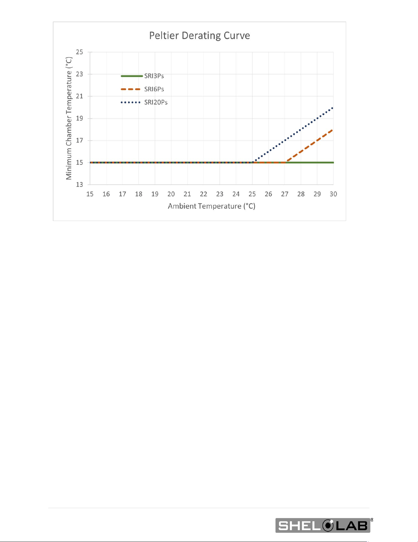
*Workspace temperatures can affect the lowest achievable operating temperature.
• SRI3P: SRI3P incubators can sustain operating chamber temperatures from 15° to 40°C in
ambient conditions ranging from 15° to 30°C.
• SRI6P: Sustained ambient temperatures of 27.1°C (80.7°F) and hotter will impact the
low-end temperature performance of the SRI6Ps. The lowest sustainable incubation
chamber temperature rises as the workspace temperature rises. See the graph on this
page.
• SRI20P: Sustained ambient temperatures of 25.1°C (77.1°F) and hotter will impact the
low-end temperature performance of the SRI20Ps. The lowest sustainable incubation
chamber temperature rises as the workspace temperature rises. See the graph on this
page.
56 | Page
57 | Page
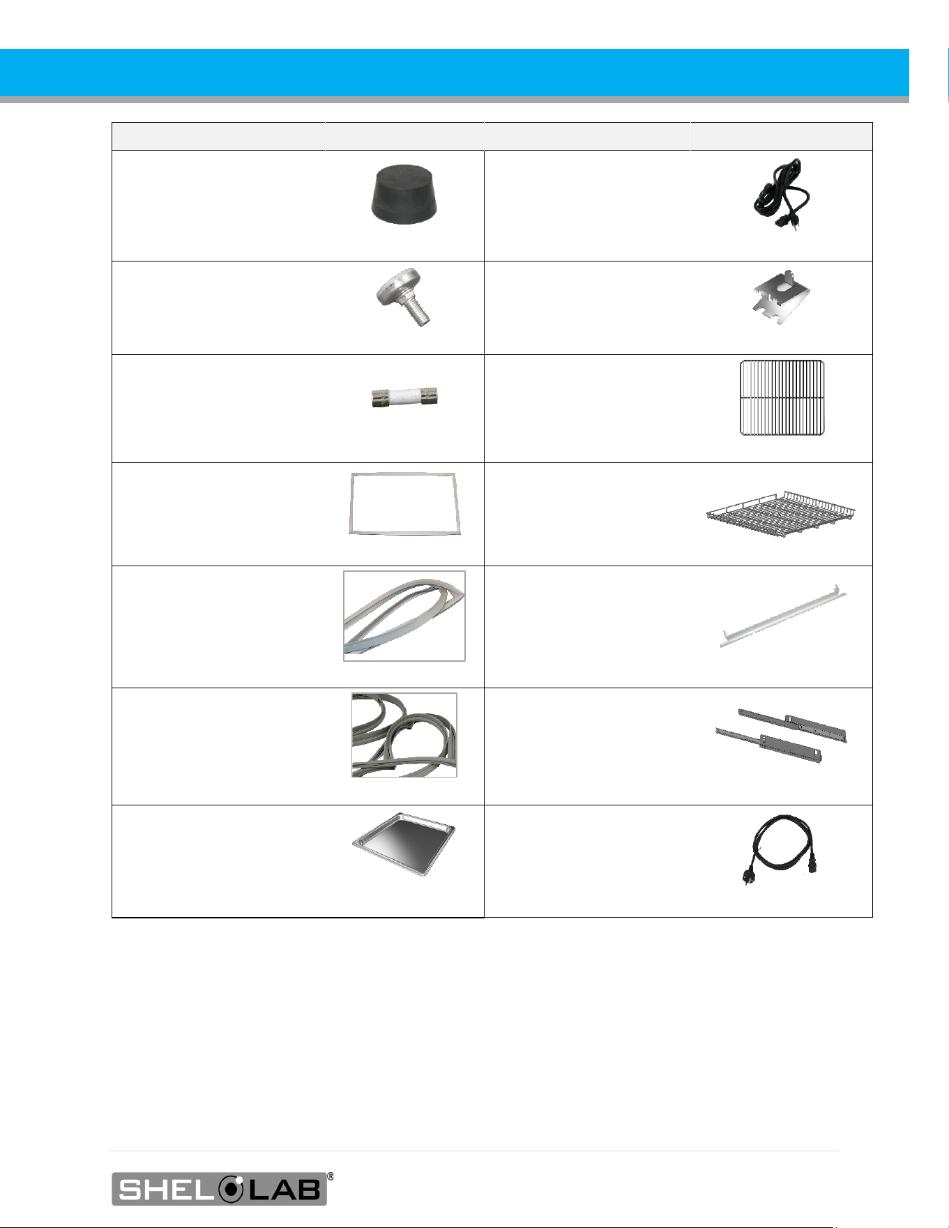
PARTS LIST
Description
Part Number
Description
Part Number
Access Port Stopper
7750517
Power Cord, 125V, 15
Amp, 8-foot (2.5m) NEMA
5-15P
1800510
Feet, Adjustable Glide
2700506
SRI3P, Shelf Clip, 1
1250512
Fuse 250V T6.3A, 5X20mm
(1, Requires 2 for operation)
3300516
SRI3P, Shelf,1
6800529
SRI3P: Gasket, Magnetic
Door (28.25 inches X 22.25
Inches)
3450758
SRI6P, SRI20P Shelf,
1
6800525
SRI6P: Gasket, Magnetic
Door (29 inches X 26 inches)
3450743
SRI6P, SRI20P, Static
Shelf Bracket, 1
5221213
SRI20P: Gasket, Magnetic
Door (29 inches X 62 inches)
3450732
SRI6P, SRI20P, Sliding
Shelf Brackets, 2
9490584
Humidity Reservoir Pan
7930514
Power Cord 250 volt, 10
Amp, 2.5m (8ft), Euro
CEE7/7
1800500
Accessories and replacement parts can be ordered online at parts.sheldonmfg.com.
If the required item is not listed online, or if you require assistance in determining which part or
accessory you need contact SHEL LAB by emailing parts@sheldonmfg.com or by calling 1-800-322-
4897 ext. 3 or (503) 640-3000 ext. 3.
Please have the model, serial, and part numbers of the unit ready. Customer Support needs this
information to match your unit to its correct part.

P.O. Box 627
Cornelius, OR 97113
USA
support@sheldonmfg.com
sheldonmanufacturing.com
1-800-322-4897
(503) 640-3000