
RESIDENTIAL
GAS TANKLESS
WATER HEATER
USER MANUAL
CS SERIES

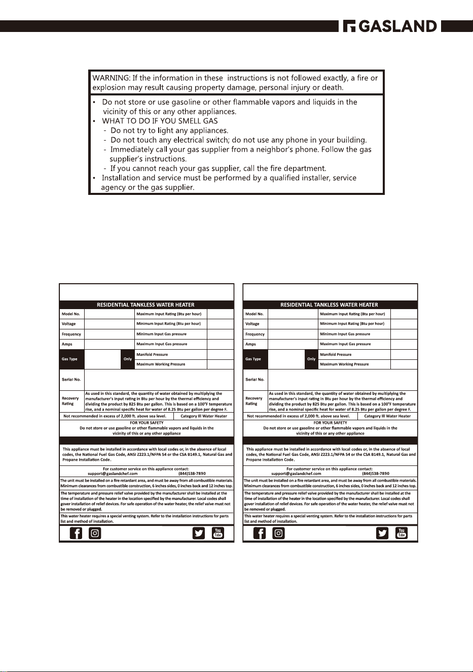
68,000
23,800
Liquid Propane
8.0” w.c
2.0 kPa
13”w.c
3.23 kPa
4.45” w.c
1.12 kPa
150 psi
CS264LP
120 Volts
60 Hz
Less than 12 Amperes
Natural Gas
68, 000
23, 800
4. 0” w.c
1 . 0 kPa
10.5” w.c
2. 61 kPa
3.5” w.c
0. 87 kPa
150 psi
CS264NG
120 Volts
60 Hz
Less than 12 Amperes
01
GASLAND GASLAND
GASLAND
GASLAND
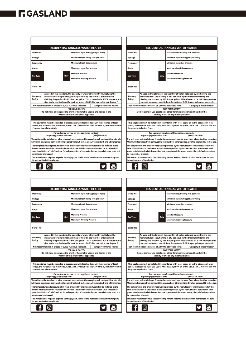
90,000
23,800
Liquid Propane
8.0” w.c
2.0 kPa
13” w.c
3.23 kPa
4.45” w.c
1.12 kPa
150 psi
CS360LP
120 Volts
60 Hz
Less than 12 Amperes
Natural Gas
90, 000
23, 800
4.0” w.c
1.0 kPa
10.5”w.c
2.61 kPa
3.5”w.c
0.87 kPa
150 psi
CS360NG
120 Volts
60 Hz
Less than 12 Amperes
102, 000
23, 800
Liquid Propane
8.0” w.c
2.0 kPa
13” w.c
3.23 kPa
4.45” w.c
1.12 kPa
150 psi
CS422LP
120 Volts
60 Hz
Less than 12 Amperes
Natural Gas
102, 000
23, 800
4. 0” w.c
1 . 0 kPa
10.5”w.c
2.61 kPa
3.5” w.c
0.87 kPa
150 psi
CS422NG
120 Volts
60 Hz
Less than 12 Amperes
02
GASLAND GASLAND
GASLAND GASLAND
GASLAND GASLAND
GASLAND GASLAND
Gasland
www.gaslandchef.com
(844)538-7890
03
Gasland
8350 Patriot Blvd STE BˈN. CharlestonˈSC 29418.
04
GASLAND
05
Contents
Operation
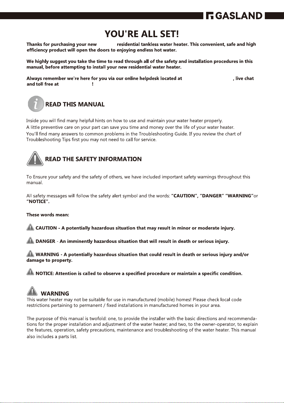
Safety Information 5-9
Installing Instructions 10-29
Warning & You're All Set 3-4
Water & gas supply connection 13-15
Relief valve & Venting 16-22
Electrical connection 22-24
Pipe installation 24-25
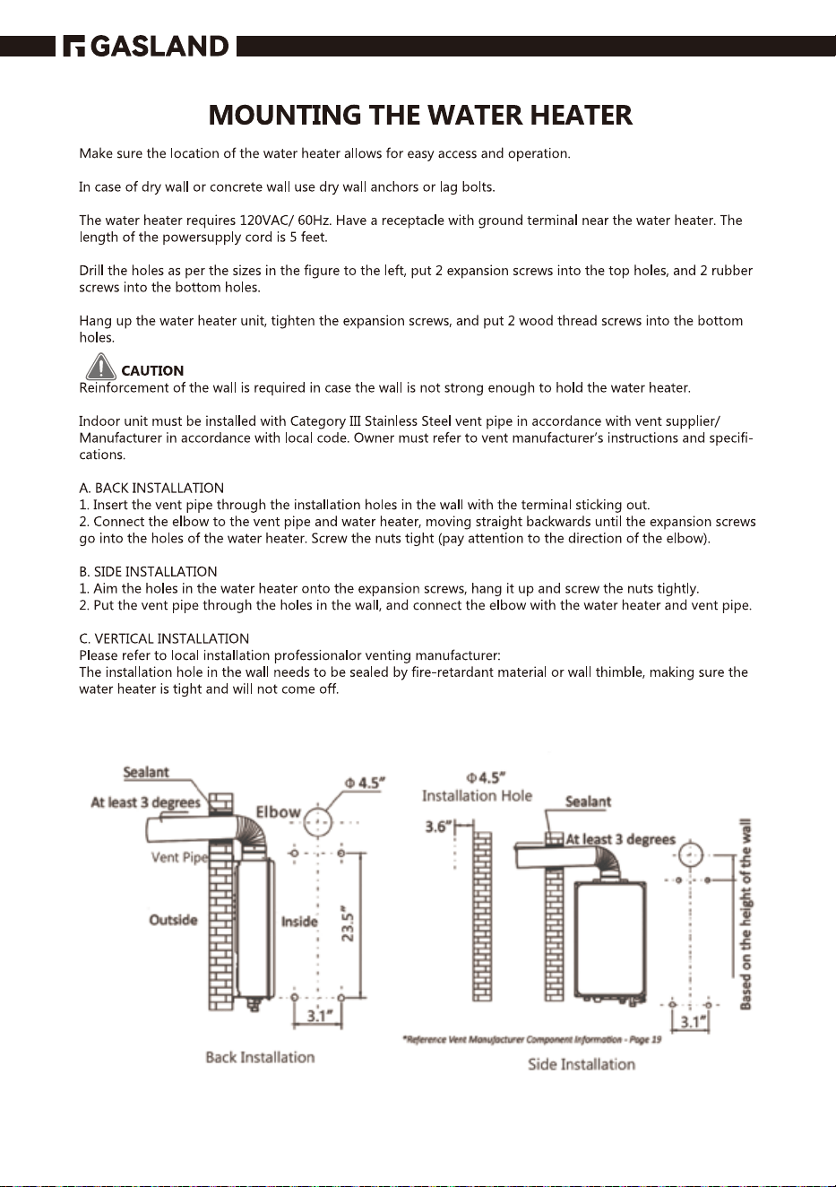
Mouting the water heater 26-29
Starting & temperature setting 29-31
Care & Maintenance
31-34
Troubleshooting
35-36
Replacement parts 37
In The Box 38
29-31
Warrranty Information 39
06
Panel Display
97
07
4
08
09
10
11
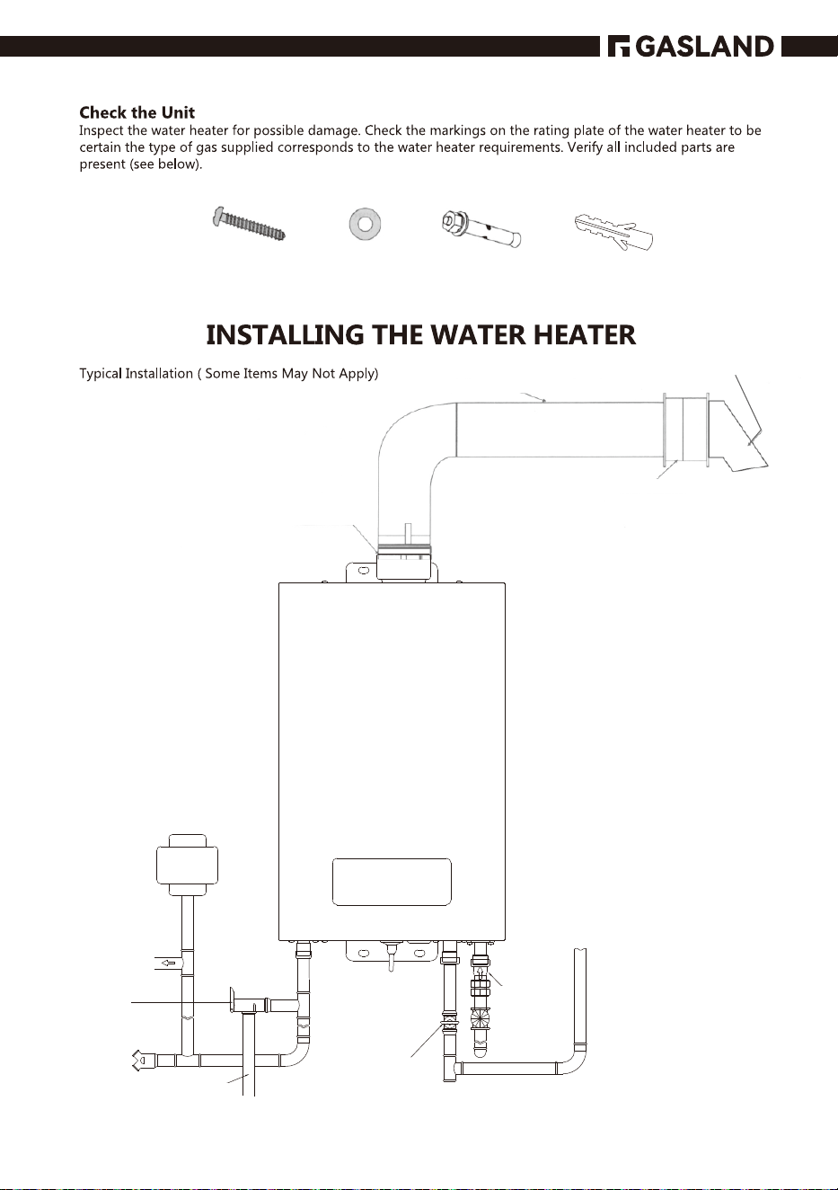
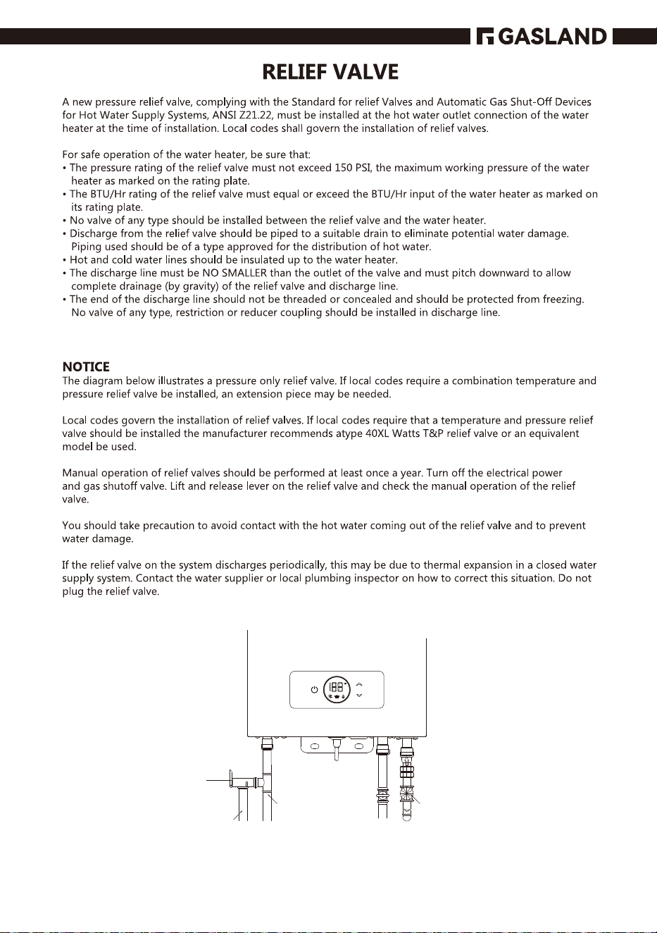
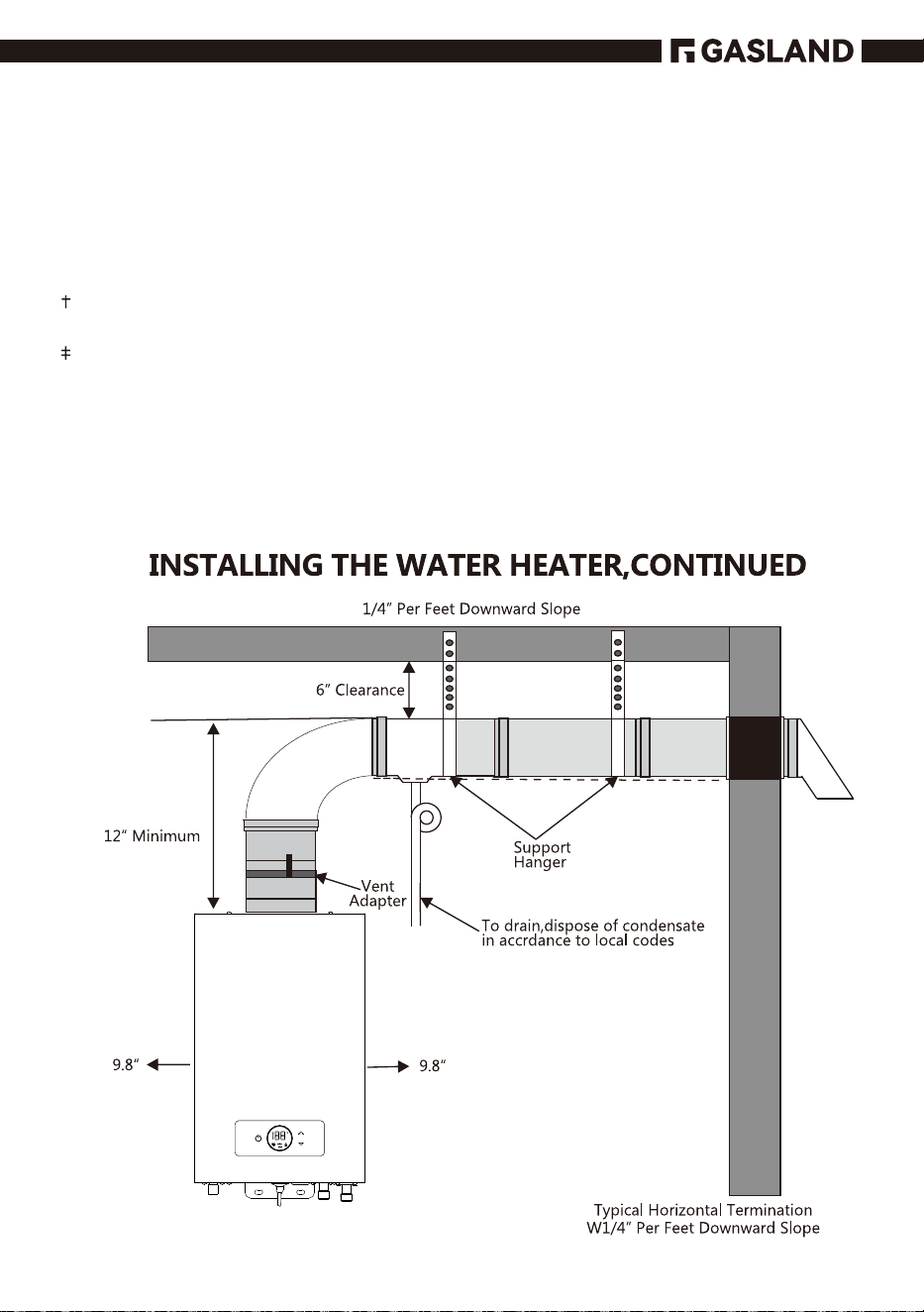
Vent Adapter
1/4” Per Foot Downward Pitch
Wall Thimble*
T
Termination
Expansion Tank
(If Needed)
To Hot Water
Faucet(s)
Pressure
˅˘Ё˘˙ˉalve
(No Supplied)
Drain Valve
Discharge Line
(To Suitable Drain)
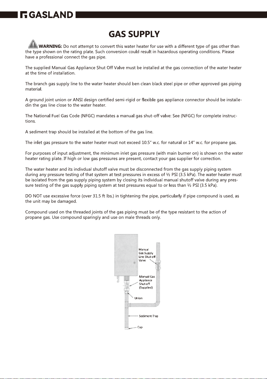
Manual Gas
Appliance
Shut-Oႇ
(No Supplied)
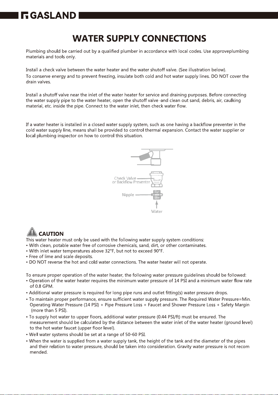
Check Valve
˂˥ʵ˔˖˞Ђˢ˪
Preventer
12
Wood Screw
x 5 pieces
Washer
x3 pieces
Exposive Screw
X 2 pieces
Wall Plug
x5 pieces
Water Inlet
Drain Valve
13
14
15
Cold Water
Supply Line
Shut-off Valve
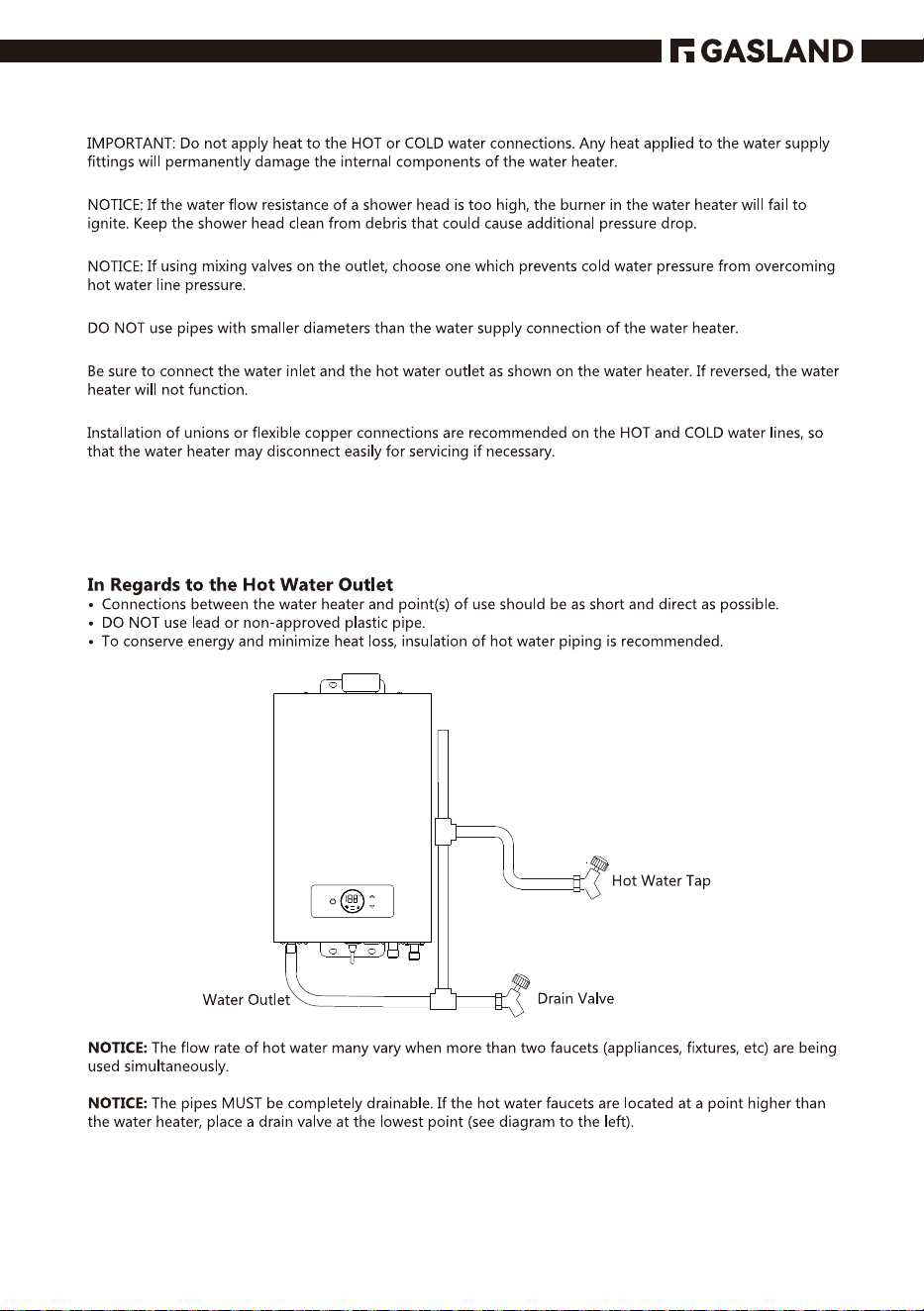
Hot Water
Supply
Outlet
Pressure
R eЁef Valve
(Not Supplied)
Discharge Line
(To Suitable Drain)
16
17
18
19
1 2
=
=
,
=
=
=
=
=
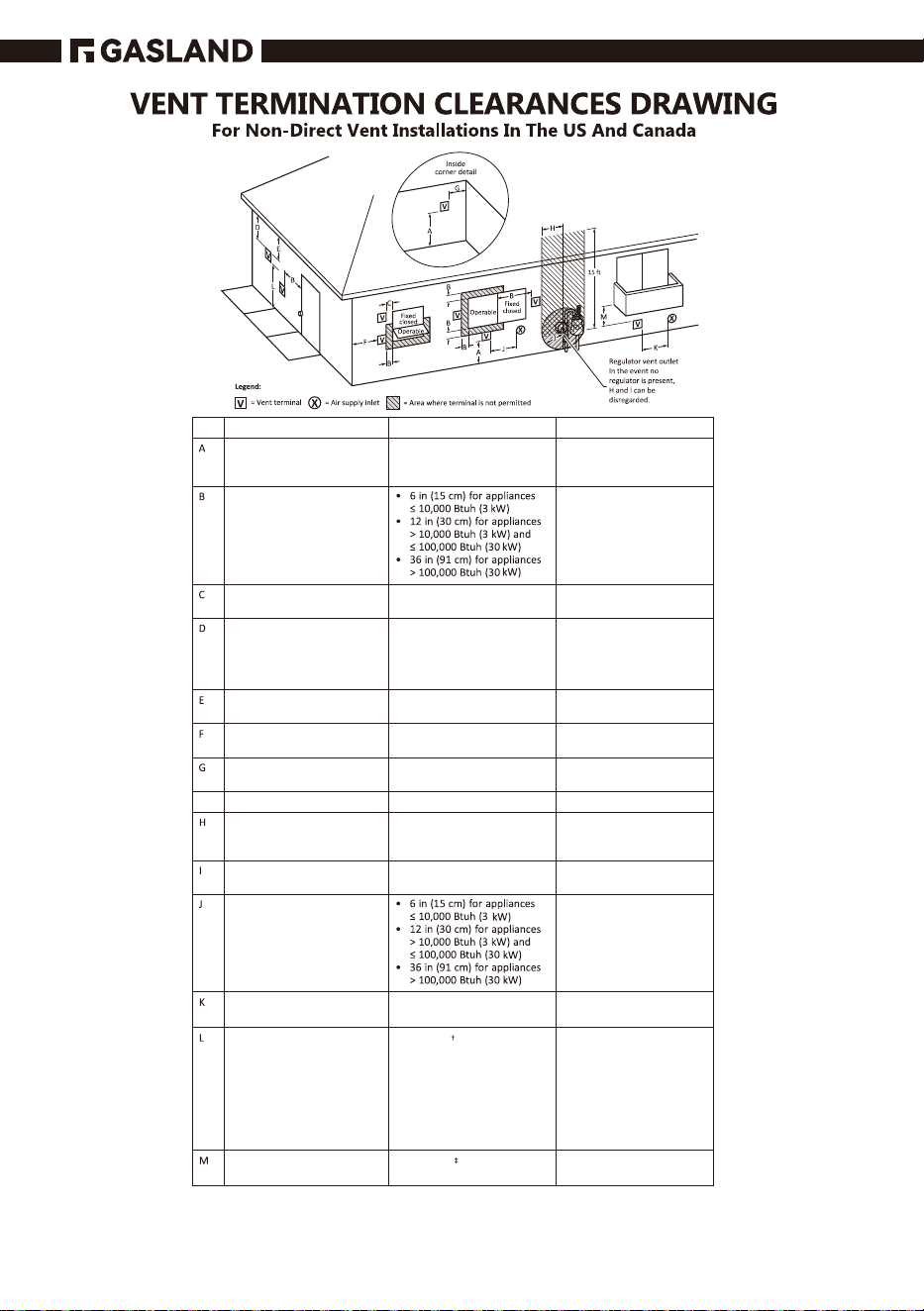
Clearance to outside corner
Clearance to inside corner
Clearance to unventilated soႈt
Vertical clearance to ventilated
soႈt located above the
terminal within a horizontal
distance of 2 ft (61 cm) from
the center line of the terminal
Clearance to permanently
closed window
Clearance to window or door
that may be opened
Clearance above grade,
veranda,porch,deck,or
balcony
12 in (30 cm)
12 in (30 cm)
US installationsCanadian installations
ʴ˦˦ˣ˘˖˜Ё˘˗˕ˬ˧˛˘
manufacturer*
ʴ˦˦ˣ˘˖˜Ё˘˗˕ˬ˧˛˘
manufacturer*
ʴ˦˦ˣ˘˖˜Ё˘˗˕ˬ˧˛˘
manufacturer*
ʴ˦˦ˣ˘˖˜Ё˘˗˕ˬ˧˛˘
manufacturer*
ʴ˦˦ˣ˘˖˜Ё˘˗˕ˬ˧˛˘
manufacturer*
ʴ˦˦ˣ˘˖˜Ё˘˗˕ˬ˧˛˘
manufacturer*
ʴ˦˦ˣ˘˖˜Ё˘˗˕ˬ˧˛˘
manufacturer*
ʴ˦˦ˣ˘˖˜Ё˘˗˕ˬ˧˛˘
manufacturer*
ʴ˦˦ˣ˘˖˜Ё˘˗˕ˬ˧˛˘
manufacturer*
ʴ˦˦ˣ˘˖˜Ё˘˗˕ˬ˧˛˘
manufacturer*
4 ft (1.2 m) below or to side of
opening; 1 ft (300 mm) above
opening
1 2
=
=
=
,
,
=
=
=
Clearance to each side of center
line extended above meter/
regulator assembly
Clearance to service regulator
vent outlet
Clearance to nonmechanical air
supply inlet to building or the
combustion air inlet to any
other appliance
Clearance to a mechanical air
supply inlet
Clearance above paved
sidewalk or paved driveway
located on public property
Clearance under veranda,
porch deck, or balcony
3 ft (91 mm) within a height 15 ft
(4.6 m)
3 ft (91 mm)
6 ft (1.83 m)
7 ft (2.13 m)
12 in (30 cm)
Canadian installations US installations
ʴ˦˦ˣ˘˖˜Ё˘˗˕ˬ˧˛˘
manufacturer*
ʴ˦˦ˣ˘˖˜Ё˘˗˕ˬ˧˛˘
manufacturer*
ʴ˦˦ˣ˘˖˜Ё˘˗˕ˬ˧˛˘
manufacturer*
4 ft (1.2 m) below or to side of
opening; 1 ft (300 mm) above
opening
3 ft (91cm) above if within
10 ft (3 m) horizontally
7 ft (2.13 m) for mechanical
draft systems (Category I
appliances). Vents for
Category II and IV appliances
cannot be located above
public walkways or other
areas where condensate or
vapor can cause a nuisance or
hazard
20
* The manufacturer shall specify a minimum clearance or state “Not applicable” in the table
and/or instructions.
i) The minimum distance from adjacent public walkways, adjacent buildings, openable
windows, and building openings shall not be less than those values specified in the
National Fuel Gas Code, ANSI Z223.1/NFPA 54, and/or the Natural Gas and Propane
Installation Code, CSA B149.1;
ii) Information on preventing blockage by snow; and
iii) Information on protecting building materials from degradation by flue gases
A vent shall not terminate directly above a sidewalk or paved driveway that is located
between two single family dwellings and serves both dwellings.
Permitted only if veranda, porch, deck, or balcony is fully ope n on a minimum of two sides
beneath the floor.
Notes:
1) In accordance with the current CSA B149.1 Natural Gas and Propane Installation Code.
2) In accordance with the current ANSI Z223.1 / NFPA 54 National Fuel Gas Code.
3) If locally adopted installation codes specify clearances different than those illustrated,then
the most stringent clearance shall prevail.
21
22
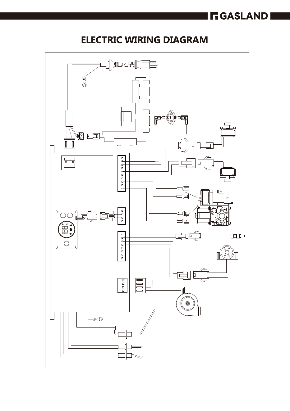
Power cord
Ground wire
Thermostat
Anti-freezer
Thermostat
Panel display
Ignition pin
Feedback wire
Ground wire
Fan
W˔˧˘˥Ђˢ˪˦˘ˡ˦ˢ˥
Temp. sensor
of water outlet
Gas main valve
Gas proportion valve
Section valve
Section valve
for certain
models
23
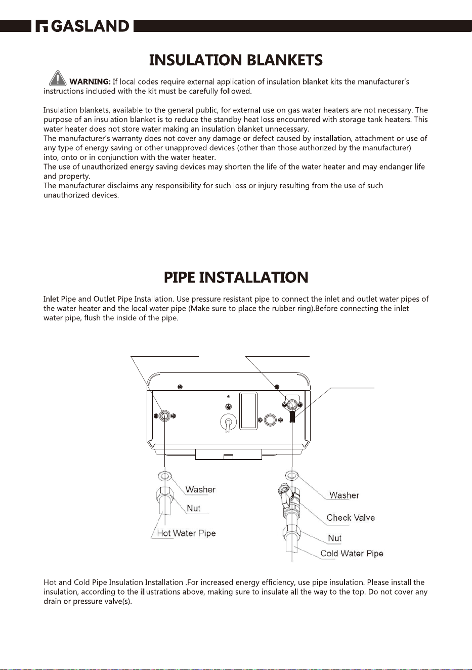
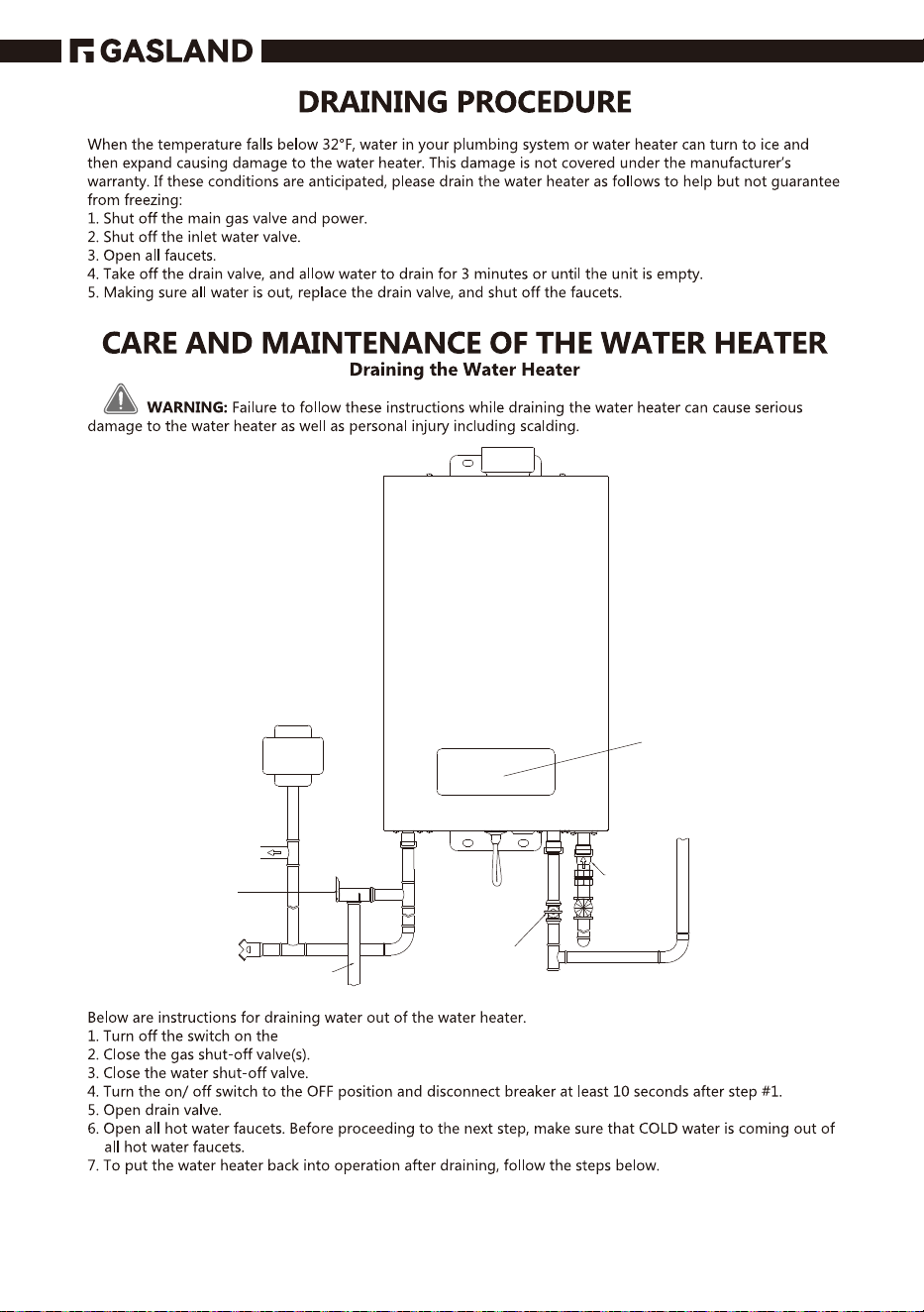
Outlet Water Pipe Inlet Water Pipe
Drain Valve
24
Check Valve
Inlet Pipe
Cold Water
Gas Inlet
25
26
27
WWW.GASLANDCHEF.COM
(844) 538-7890
SUPPORT@GASLANDCHEF.COM
CS SERIES GASLAND
28
29
30
31
gasland
www.gaslandchef.com or call (844) 538-7890.
gasland
32
33
panel display.
Panel display(Indoor)
Expansion Tank
(If Needed)
To Hot Water
Faucet(s)
Pressure
˅˘Ё˘˙ˉalve
(No Supplied)
Drain Valve
Discharge Line
(To Suitable Drain)
Manual Gas
Appliance
Shut-Oႇ
(No Supplied)
Check Valve
˂˥ʵ˔˖˞Ђˢ˪
Preventer
34
panel display.
35
panel display.
panel display
panel display.
panel display.
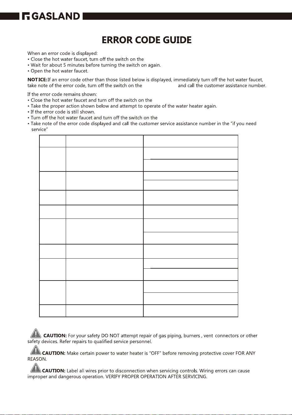
Error
Code
A1
A3
A4
A5
A7
A8
A9
Ab
FF
Error Description
Water outlet
temperature sensor
failure
Fan failure
Ignition failure
Accidental flameout failure
Water outlet
temperature
overtemperature failure
Fake flame failure
The thermostat
(overheating) is
out of order
Solenoid valve failure
Vent blockage
What To Do
connect the water inlet
temperature sensor
replace the water inlet
temperature sensor
connect the fan
replace the fan
Turn off the hot water faucet or
turn off the switch on the display
Turn off the hot water faucet or
turn off the switch on the display
connect the water outlet
temperature sensor
replace the water outlet
temperature sensor
Turn off the hot water faucet or
turn off the switch on the display
connect the thermostat
replace the thermostat
connect the valve
replace the valve
clean the vent pipe
36
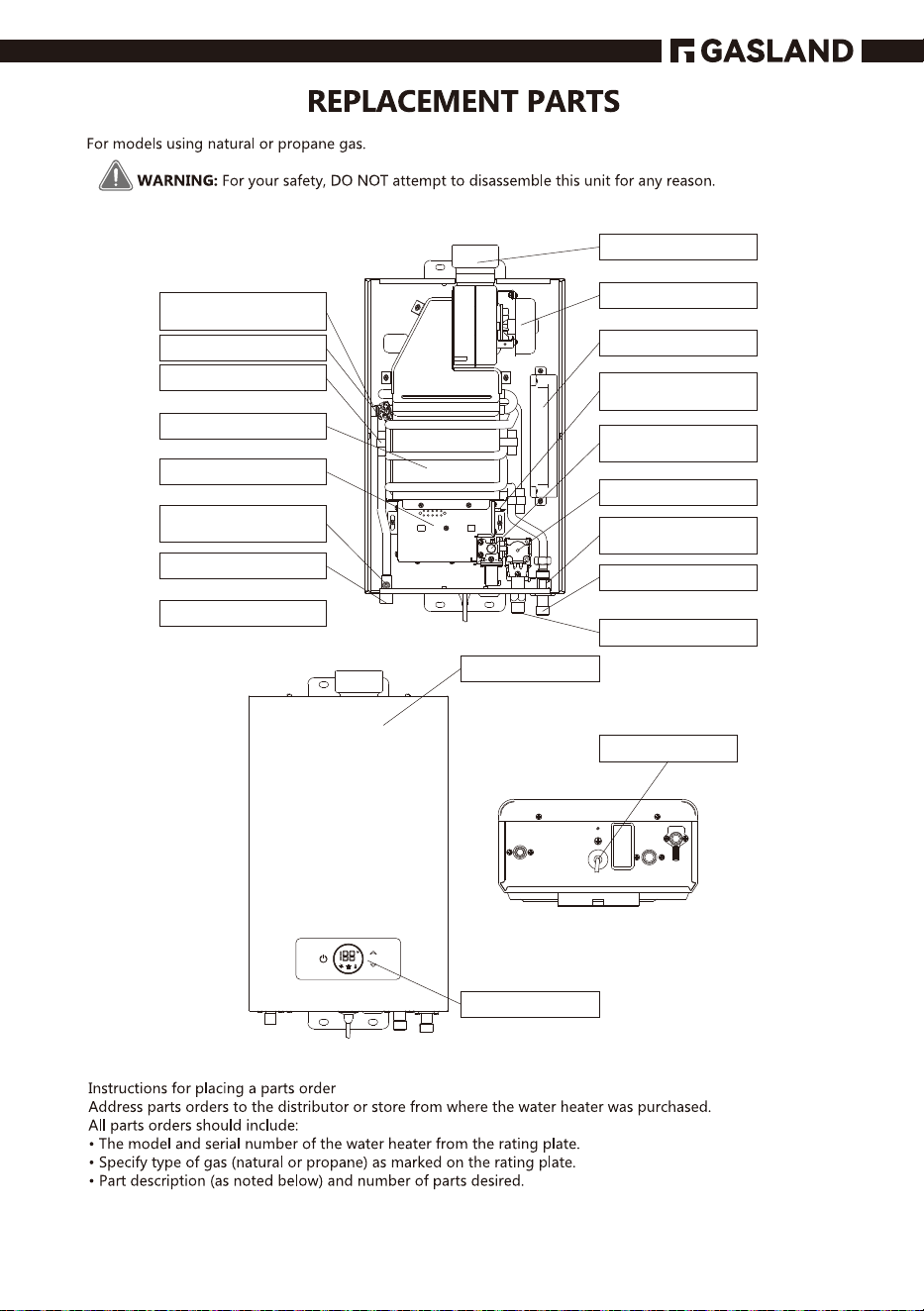
Exhaust outlet
Anti-freezer
thermostat
Thermostat
Anti-freezer
Heat exchanger
Burner assembly
Fan assembly
Hot water
T
emp.
sensor
Water Outlet
Water Inlet
Gas Inlet
Water Flow
Sensor
Gas Valve Asm.
Gas Distribution
Pipe
Ignition Pin &
Flame Sensor Pin
Computer board
Exhaust outlet
Front Cover
Panel Display
Power Cord
37
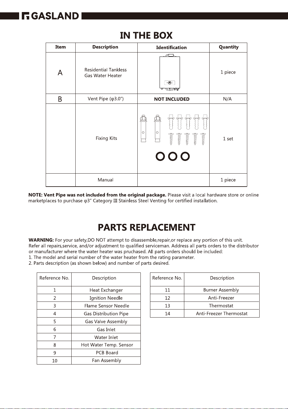
C
D
38
Gasland
Gasland
Gasland Gasland
GASLAND GASLAND
Gasland
Gasland
Gasland
Gasland
Gasland
Gasland
Gasland
Gasland
39


8350 Patriot Blvd STE B,
N. Charleston, SC 29418
1 (844) 538-7890
www.gaslandchef.com [email protected]
SCAN ME
