USER MANUAL
Warning notices: Before using this product, please read this manual carefully and keep it for future reference.
The design and specifications are subject to change without prior notice for product improvement.
Consult with your dealer or manufacturer for details.
The diagram above is just for reference. Please take the appearance of the actual product as the standard.
Instantaneous Gas Water Heater
Indoor Series
MGWH150ISNN
MGWH150ISPN
MGWH199ISNN
MGWH199ISPN

THANK YOU LETTER
Thank you for choosing Midea! Before using your new Midea product, please read
this manual thoroughly to ensure that you know how to operate the features and
functions that your new appliance offers in a safe way.
CONTENTS
THANK YOU LETTER
SAFETY INSTRUCTIONS
SPECIFICATIONS
PRODUCT OVERVIEW
QUICK START GUIDE
PRODUCT INSTALLATION
OPERATION INSTRUCTIONS
CLEANING AND MAINTENANCE
TROUBLESHOOTING
CERTIFICATIONS AND SAFETY APPROVALS
TRADEMARKS, COPYRIGHTS AND LEGAL STATEMENT
DISPOSAL AND RECYCLING
DATA PROTECTION NOTICE
Do not try to light any appliance.
Do not touch any electrical switch; do not use any phone in your building.
lmmediately call your gas supplier from a neighbor's phone.
Follow the gas supplier's instructions.
lf you cannot reach your gas supplier, call the fire department.
Installation and service must be performed by a qualified installer, service agency, or
the gas supplier.
WHAT TO DO IF YOU SMELL GAS:
Do not store or use gasoline or other flammable vapors and liquids in the vicinity of
this or any other appliance.
WARNING: lf the information in these instructions is not followed exactly a
fire or explosion may result causing property damage, personal injury, or death.
●
●
●
●
●
●
●
01
02
13
15
20
21
43
47
52
56
57
58
59
01
Incorrect installation may cause serious damage or injury!
The seriousness of potential damage or injuries is classified as either a WARNING! Or
CAUTION!
Read Before Installation!
Explanation of Symbols
SAFETY INSTRUCTIONS
Warning
This symbol indicates ignoring instructions may cause death or serious injury.
Caution
This symbol indicates that ignoring instructions may cause moderate
personal injury, damage to the unit, or other property.
DO NOT
This symbol indicates that you should NEVER perform the indicated
action.
Properly install water heate
Be sure to read and understand the entire user manual before attempting to install or operate
this appliance. It may save you time and money. Pay particular attention to the Safety
Instructions. Failure to follow these warnings could result in serious bodily injury or death.
Should you have problems understanding the instructions in this manual, or have any
questions, STOP, and get help from à qualified service technician, or the local gas utility.
Important Safety Information Read All
Instructions Before Using
DANGER
Failure to properly install the appliance indoors as outlined in the Installation Guide in this
manual can result in unsafe operation of the water heater. To avoid the risk of fire, explosion,
or asphyxiation from carbon monoxide, never operate this appliance unless it is installed
properly and has an adequate air supply for proper operation. Be sure to inspect the flue
terminal for proper installation at initial start-up and at least annually thereafter. Refer to the
Care & cleaning section of this manual for more information regarding flue terminal
inspection.
WARNING
Gasoline, as well as other flammable materials and liquids (adhesives, solvents, paint thinners
etc.), and the vapors they produce are extremely dangerous. DO NOT handle, use or store
gasoline or other flammable or combustible materials any where near or in the vicinity of a
appliance or any other appliance. Be sure to read and follow the labels on the appliance as
02
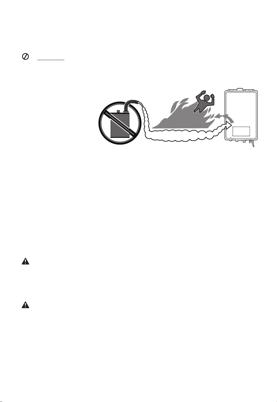
DO NOT use or storeflammable products such as gasoline, solvents or adhesives in
the same room or area near the appliance.
Vapors from flammable liquids will explode and catch fire causing death or
severe burns.
Keep flammable products:
1. Far away from heater
2.In approved containers
3. Tightly closed
4.Out of children’s reach
The appliance has a main
burner flame.The main burner
flame
1. Can come on at any time
2. Will ignite flammable vapors
Vapors:
1. Cannot be seen
2. Are heavier than air
3. Go a long way on the floor
4. Can be carried from other rooms to the main burner flame by air currents
Installation:
Do not install the appliance where flammable products will be stored or used unless the main
burner flame ls at least 18” above the floor. This will reduce, but not eliminate, the risk of
vapors being ignited by the main burner flame.
Read and follow water heater warnings and instructions, lf user manual is missing,contact the
retailer or manufacturer.
well as the warnings printed in this manual: Failure to do so can result in property damage,
bodily injury or death.
WARNING: California Proposition 65
This appliance contains chemicals known to the State of California to cause cancer, birth
defects, or other reproductive harm. If the information in these instructions is not followed
exactly, a fire or explosion may result causing property damage, personal injury or death. Do
not discard this manual. Please read carefully and keep in a safe place for future reference.
WARNING
• This appliance is not approved for use in manufactured (mobile) homes! Please check local
code restrictions pertaining to permanent/ fixed installations in manufactured homes in
your area.
• Improper installation, adjustment, alteration, service or maintenance can cause death,
personal injury, or property damage. Refer to this manual. Installation and service must be
performed by a qualified installer, service agency or the gas supplier.
Flammable
Flammable Vapors
03
NOTICE: use or storeflammable products such as gasoline, solvents or adhesives in the
same room or area near the appliance.
Properly install water heater
DANGER
Failure to properly install the appliance outdoors as outlined in the installation guide in this
manual can result in unsafe operation of the appliance. To avoid the risk of fire, explosion, or
asphyxiation from carbon monoxide, never operate this appliance unlessit is installed properly
and has an adequate air supply for proper operation. Be sure to inspect the flue terminal for
proper installation at initial start-up, and at least annually thereafter.
• Combustible construction refers to adjacent walls and ceilings and should not be confused
with combustible or flammable products and materials. Combustible materials, such as
clothing, cleaning materials. or flammable liquids, should never be stored in the vicinity of
this appliance or any gas appliances. Fire or explosion can occur causing death, personal
injury, and/or property damage
• Gas detectors are recommended in propane and natural gas applications and their
installation should be in accor dance with the detector manufacturer’s recommendations
and/or local laws, rules, regulations or customs.
• Water heaters utilizing propane gas are different from natural gas models. A natural gas
water heater will not function safely on propane gas and vice versa.
• No attempt should ever be made to convert the appliance from natural gasto propane gas.
To avoid possible equipment damage, personal injury or fire, do not connect the water
heater to a fuel type not in accordance with the appliance data plate; propane for propane
units and natural gas for natural gas units. These appliances are not certified for any other
fuel type.
• With clean, potable water free of corrosive chemicals, sand, dirt, or other contaminaznts.
• With inlet water temperature above 32°F(O°C), but not exceeding 118°F(48°C).
Natural gas and liquefied petroleum models safety
DANGER
Both propane and natural gas have odorants added to aid in detecting a gas leak. Some
people may not physically be able to smell or recognize this odorants. If you are unsure or
unfamiliar with the smell of propane or natural gas, ask the gas supplier.
Other conditions, such as “odorants fade”, which causes the odorant to diminish in intensity,
can also hide or camouflage a gas leak. Always check with commercial leak odorants or
soapy water
CAUTIONS
This appliance must only be used with the following water supply system conditions:
Be sure to read and understand the entire user manual before attempting to install or operate
this appliance. It may save your time and money. Pay particular attention to the Safety
Instructions. Failure to follow these warnings could result in death or serious bodily injury.
Should you have problems understanding the instructions in this manual, or have any
questions, STOP and get help from a qualified service technician or the local gas utility
Read all instructions before using
DO NOT reverse the hot and cold water connections. The appliance will not operate.
04
DO NOT Tattempt to find the cause yourself.
DO NOT try to light any appliance.
DO NOT touch any electrical switch.
DO NOT use any phone in your building.
NOTICE: If a gas leak is present or suspected:
For your safety read before operating
• Propane water heaters should not be installed below grade (for example in a basement) if
such installation is prohibited by federal, state and/or local laws, rules, regulations or
customs.
• Propane or propane gas must be used with great caution. It is heavier than air and will
collect first in lower areas making it hard to detect at nose level.
• Before attempting to light the appliance, make sure to look and smell for gas leaks. Use a
soapy solution to check all gas fittings and connections Bubbling at a connection indicates
a leak that must be corrected. When smelling to detect a gas leak, be sure to sniff near the
floor also.
• It is recommended that more than one method, such as soapy solution, gas detectors, etc.,
be used to detect leaks in gas applications.
• Leave the house immediately and make sure your family and pets leave also.
• Leave the doors open for ventilation and contact the gas supplier, a qualified service agency
or the fire department
• Stay away from the house(or building) until the service call has been made, the leak is
corrected and a qualified agency has determined the area to be safe.
• Follow the steps listed under “WHAT TO DO IF YOU SMELL GAS” found on Page 9 of this
manual.
CAUTIONS
• DO NOTattempt repair of electrical wiring, gas piping, burners, vent connectors, or other
safety devices. Refer repairs to qualified service personnel
• Turn off the manual gas shut off valve if the appliance has been subjected to overheating,
fire, flood, physical damage, or if the gas supply fails to shut off.
• DO NOT turn on the appliance unless the water and gas supplies are completely opened.
A. This appliance does not have a pilot. It is equipped with an ignition device which
automatically lights the burner. Do not try to light the burner by hand.
B. Before operating, smell all around the appliance are for gas. Be sure to smell next to the
floor because some gasis heavier than air and will settle on the floor.
WARNING
• The installation must conform to local codes or.in the absence of localcodes.the National
Fuel Gas Code,ANS|Z23.1/NFPA 54, and/or CSA B149.1, Natural Gas and Propane Installation
Code
• Should overheating occur or the gas supply fail to shut off, turn off the manual gas control
valve to the appliance.
WARNING
If you do not follow these instructions exactly, a fire or explosion may result causing property
damage, personal injury or loss of life.
05
DO NOT try to light any applíance.
DO NOT touch any electrical switch, do not use any phone in your building.
DO NOT return to your home until authorized by the gas supplier or fire
department.
DO NOT use this appliance if any part has been under water. Immedi ately call a
qualified service technician to inspect the appliance and to replace any part of the control
system and any gas control which has been under water.
• Immediately call your gas supplier from a neighbor's phone. Follow the gas supplier’s
instructions
• If you cannot reach your gas supplier, call the fire department.
• Use only your hand to push in or turn the gas control knob. Never use tools If the knob will
not push in or turn by hand, do not try to repair it. call a qualified service technician. Force
or attempted repair may result. in a fire or explosion
1. STOP! Read the safety information above on this manual.
2. Turn off all electric power to the appliance.
3. Do not attempt to light the burner by hand.
4. Turn the gas shut off valve located on the outside of the unit clockwise to the “OFF”
position.
5. Turn off all electrical power to the appliance
6. Wait five(5) minutes to clear out any gas. If you smell gas, STOP! Follow “B” in the safety
information above on this manual. If you don’t smell gas, go to the next step.
7. Turn the gas shut off valve located on outside of the unit counterclock wise to the “ON”
position.
8. Turn on all electric power to the appliance.
9. Set thermostat to desired setting
10. If the appliance will to operate, follow the instructions “To Turn Off Gas To Appliance” and
call your service technician or gas supplier.
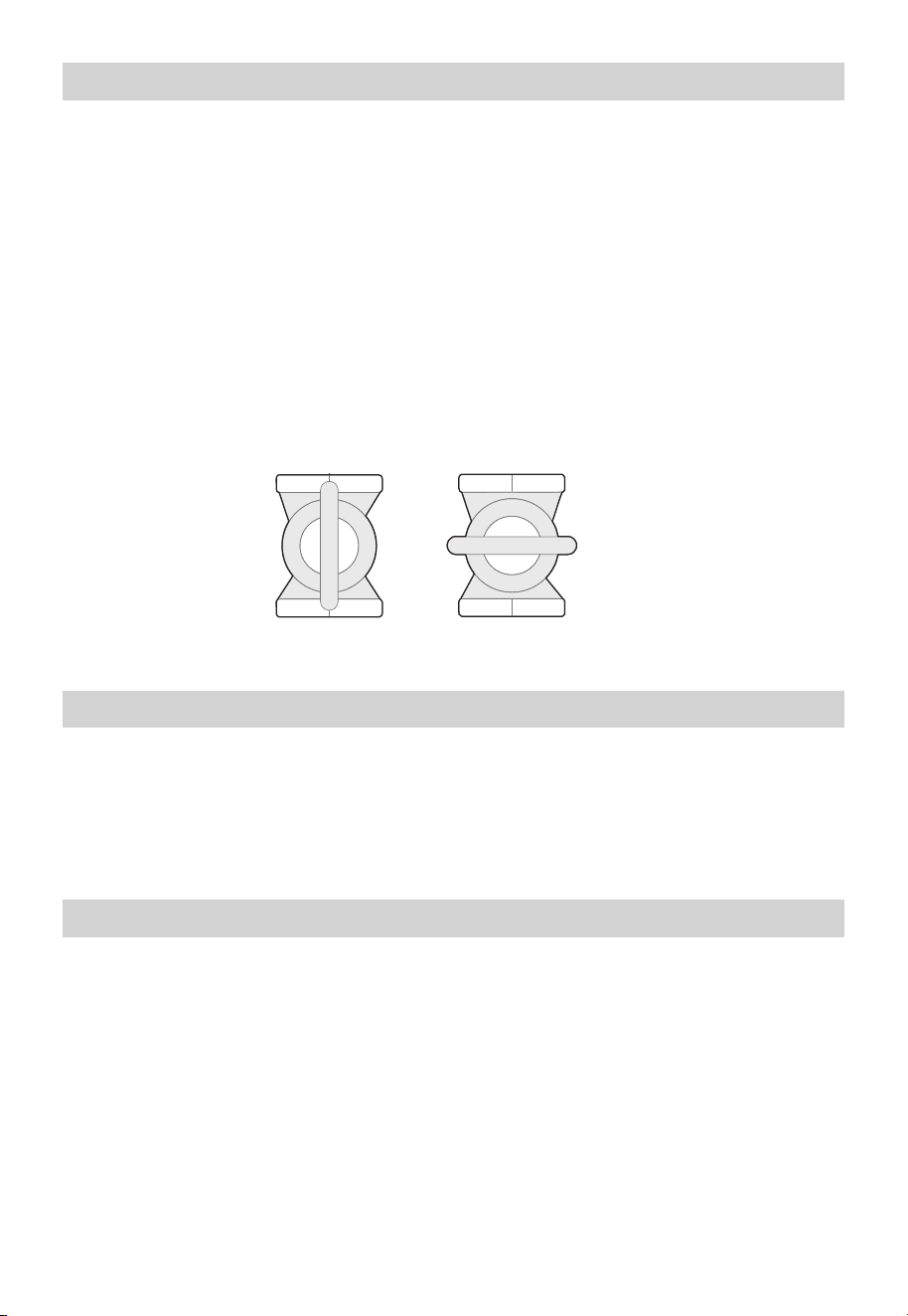
Operating instructions
1. Turn off all electric power to the appliance if service is to be performed.
2. Turn the gas shut-off valve located on the outside ofthe unit clockwise to the “OFF”
position.
To turn off gas to appliance
What to do if you smell gas
Gas Shut-Off
Valve
Open Close
06
CAUTIONS
• Label all wires prior to disconnecting for service. Wiring errors can cause dangerous and
improper operation. Verify correct operation after servicing.
• For your safety, burner inspection and cleaning should be performed only by qualified
service personnel.
• Make certain the power to the appliance is OFF before removing the unit cover panel.
Expose electrical components and moving parts can cause personal injuries
• For your safety, DO NOTattempt repair of electrical wiring, gas piping burners, vent
connectors, or other safety devices. Refer repairs to qual fied service personnel.
• Read this manual entirely before installing or operating the appliance
• Use this appliance only for its intended purpose as described in this user manual and Care
Manual
• Be sure your appliance is properly installed in accordance with local codes and the provided
installation instructions.
• Part of the appliance unless it is specifically recommended in this manual.
• All other servicing should be referred to a qualified technician.
Safety precautions
Have the installer show you the location of the gas shut off valve and how to shut it off if
necessary. Turn off the manual shut off valve if the appliance has been subjected to
overheating, fire, flood, physical damage or if he gas supply fails to shut off.
Electrical safety
DANGER
Shock hazard-make sure the electrical power to the subjected is off to avoid electric shock
that will result in death or serious personal injury.
WARNINGS
• For your safety, the information in this manual must be followed to minimize the risk of fire,
explosion, or electric shock that can result in death, personal injury, and/or property
damage
• If an external electrical source is utilized, the appliance, when installed, must be electrically
grounded in accordance with local codes or, in the absence of local codes, with the National
Electrical Code, ANSI/NFPA 70, and/or the CSA C22.1, Canadian Electrical Code, Partl.
California Law gas tankless that gas tankless water heaters must be braced,anchored or
strapped to resist falling or horizontal displacement due to earthquake motions. For gas
tankless water heaters up to 52 gallon capacity, a brochure with generic earthquake bracing
instructions can be obtained fromthe warranty card ask a water heater dealer However,
applicable local codes shall water heater govern installation. For gastankless water heater of a
capacity greater than 52 gallons or tankless style,consult the local building jurisdiction code
for acceptable bracing procedures.
For installations in the state of california
07

• Read this manual entirely before installing or operating the appliance
• Use this appliance only for its intended purpose as described in this user manual.
• Be sure your appliance is properly installed in accordance with local codes and the provided
installation guide
• Part of the appliance unless it is specifically recommended in this manual.
• All other servicing should be referred to a qualified technician.
• Installation distances may vary by local code. It is the installer’s responsibility to verify
installation requirement
• Make sure before installation that the gas type will use is the same type on the data plate
• The appliance unit should be installed by professionals. Improper installation may cause
failure or dangerous conditions such as gas leaking or explosion.
• This appliance cannot be installed in an UN-VENTED bathroom, bed room, basement, living
room, closet, outdoor, stairway or an exit area. lf installed in an exit area, it must be at least
16.5ft or more way from the exit.
• Vent pipe should extend from the wall at least 2”. The terminal must be atleast 1.64 ft away
from obstruction,and must be well vented
• Vent pipe should slope 3° downward, to avoid condensing water and protect from rain
entering.
• Vent pipe should avoid direct, strong wind because the downdraft will tcause malfunction.
• The appliance should be installed far from any blockage, and with plenty of enough space
for installationv and maintenance. Adequate clearances for servicing must be provided.
• The appliance should not be installed in the same room with a gas stove.
• When determining the floor clearance, a clearance of 6” must be main tained between the
vent pipe and combustible material. A side wall clearance of 6" and a top clearance of 12”
must be maintained
• The vent pipe can be up 32ft in length with one elbow.
• The vent pipe should be installed with a flame retardant wall thimble Owner must refer to
vent manufacturer’s instructions and specifications.
• The power socket connecting the appliance should be grounded properly with a GFCI
circuit protector.
• The appliance should not be located in an area where leakage of the heat exchanger or
connections will result in damage to the area adjacent to it or to lower floors of the
structure. When such areas cannot be avoided it is recommended that a suitable catch pan,
adequately drained, must e installed under the appliance. The pan must not restrict com
bustion airflow.
• The restrict should be installed as close as practical to have termi nation to minimize vent
length and the number of elbows required for venting.
• A gas fired water heater or any other appliance should not be installed in a space where
liquids which give off flammable vapors are to be used or stored. Such liquids include
gasoline, propane gas (butane or propane), paint or adhesives and their thinners, solvents
or removers.
• The appliance should be installed far from heat sources, flammable and dan gerous
materials. Because of natural air movement in a room or other enclosed space, flammable
vapors can be carried some distance from where their liquids are being used or stored. The
open flame of the appliance’s main burner can ignite these vapors causing an explosion or
fire which may result in severe burns, death or property damage.
Selecting location
08
DO NOT install appliance where subject to vibrations or on the road use.
DO NOT install the appliance in Recreational Vehicles, Mobile Homes Boats and
other Watercraft.
DO NOT install the appliance near vents for heating or cooling. A minimum of 4 feet
should be maitained.
WARNING
Combustible construction refers to adjacent walls and ceilings and should not be confused
with combustible or flammable products and materials. Combustible and/or flammable
products and materials should never be stored in the vicinity of this or any gas appliance.
Proper operation of the appliance requires air for combustion and ventilation. Provisions for
combustion and ventilation air must comply with referenced codes and standards.
• Raising the water heater will reduce, BUT NOT eliminate the possibility of lighting the vapor
ofany flammable liquids which may be improperly stored or accidentayspied.
• If the appliance is installed in a garage, it should be installed so that the direct ignition
system and main burner are no less than 18” above the garage floor.
• Hot and cold water lines should be insulated to conserve water and energy.
• The appliance must be located so it is not subject to physical damage. for example, by
moving vehicles, area flooding. etc.
• The appliance should be installed with the proper venting materials and termination suitable
for Categorylll venting. Failure to install and properly vent the appliance to the outdoors as
outlined in the Venting
• Section of this manual can result in unsafe operation. Owner must refel to vent
manufacturer’s instructions and specifications.
• For other than a direct vent appliance, the appliance must be located as close as practicable
to a chimney or gas vent.
• If the clearances stated on the instruction/warning label, located on the front pane of the
heater fifer, install the appliance according to the clearances stated on the manual.
A confined space is one having a volume of less than 50 cubic feet per 1,000 BTU/Hr of the
aggregate input of all appliances within that space.
The air must be supplied through two permanent openings of equal area. One is to be located
with 12” above the floor and the other is to be located within 12” below the ceiling.
The minimum net free area of each opening must not be less than one square inch per 1,000
BTU/Hr of the total input rating of all the appliance in the enclosure (but not less than 100
square inches), if each opening communicates with other unconfined areas inside the
building.
Combustion and Ventilation A:
Air Openings
Min 200 sp.ln
Min.4”
09

NOTICE: If the appliance is installed in an unconfined space w ithin a building of
conventional frame, masonry or metal construction, infiltration air is normally adequate for
proper combustion and ventilation. If the appliance is installed in a confined space, provisions
for combustion and ventilation air must be made.
NOTICE: If the duct openings which supply combustion and ventilation air are to be
covered with a protective screen or grill, the net free area (openings in the material) of the
covering material must be used in determining the size of the openings. Protective screening
for the openings MUST NOT be smaller than 1/4” to prevent clogging by lint or other debris.
NOTICE: The appliance should not be installed near any air supply containing halogenated
hydrocarbons.
Buildings of unusually tight construction shall have the combustion and ventilation air
supplied from outdoors, or a freely ventilated attic or crawl space. If air is supplied from
outdoors, directly or through vertical ducts, there must be two openings located as specified
above and each must have a minimum net free area of not less than one square inch per
4,000 BTU/Hr of the total input rating of all the appliances in the enclosure.
If horizontal ducts are used to communicate with the outdoors, each opening must have a m
inim um net free area of not less than one square inch per 2,000 BTU/Hr of the total input
rating of all the appliances in the enclosure. If ducts are used, the m inim um dimensions of
rectangular air ducts shall not be less than 4”.
The air in beauty shops, dry cleaning establishments, photo processing labs, and storage
areas for liquid and powdered bleaches or swimming pool chemicals often contain such
halogenated hydrocarbons.
An air supply containing halogenated hydrocarbons may be safe to breathe, but when it
passes through a gas flame corrosive elements are released that will shorten the life of any
gas burning appliance.
Propellants from common spraycans or gas leaks from A/C and refrigeration equipm ent are
highly corrosive after passing through a flame.
The appliance warranty is voided when failure of the appliance is due to operation in a
corrosive atmosphere.
Corrosive atmospheres
Inspect the appliance for possible damage. Check the markings on the rating plate of the
appliance to be certain the type of gas supplied corre sponds to the appliance requirements.
Verify all included parts are present (Check details from In The Box at Page 16.
Check the unit
10
IMPORTANT: Do not apply heat to the HOT or COLD water connections.
Any heat applied to the water supply fittings will permanently damage the internal
components of the appliance.
Plumbing should be carried out by a qualified plumber in accordance with local codes. Use
approved plum bing materials and tools only.
Install a checkvalve between the appliance and the water shut off valve.
To conserve energy and to prevent freezing, insulate both cold and hot water supply lines.
DO NOT cover the drain valves. Install a shut off valve near the inlet of the appliance for
service and draining purposes. Before connecting the water supply pipe to the appliance,
open the shut off valve and clean out sand, debris, air, caulking material, etc inside the pipe.
Connect to the water inlet, then check water flow. Close the shut off valve and clean the water
filter.
If a appliance is installed in a close water supply system, such as one having a backflow
preventer in the cold water supply line, means shall be provided to control thermal expansion.
Contact the water supplier or local plum bing inspector on how to control this situation.
To ensure proper operation of the appliance, the following water pressure guidelines should
be followed:
• Operation of the appliance requires the m inim um water pressure of 14 PSI and a m inim um
water flow rate of 0.75 GPM.
• Additional water pressure is required for long pipe runs and outlet fitting(s) water pressure
drops.
• To maintain proper performance, ensure sufficient water supply pres sure. The Required
Water Pressure=Min. Operating Water Pressure (14 PSI)+Pipe Pressure Loss +Faucet and
Shower Pressure Loss + Safety Margin (more than 5 PSI).
• To supply hot water to upper floors, additional water pressure (0.44 PSI / FT) must be
ensure.
• The measurement should be calculated by the distance between the water inlet of the
appliance (ground level) to the hot water faucet (upper floor level).
• Well water systems should be set at a range of 50-60 PSI.
• When the water is supplied from a water supply tank, the height of the tank and the
diameter of the pipes and their relation to water pressure, should be taken into
consideration. Gravity water pressure is not recom mended.
Water supply connections
Water
Body
Check Valve
Maximum Flow
Water Inlet
Nipple
11

DO NOT use pipes with smaller diameters than the water supply connection of the
appliance.
NOTICE: If the water flow resistance of a shower head is too high, the burner in the
appliance will fail to ignite. Keep the shower head clean from debris that could cause
additional pressure drop.
NOTICE: If using mixing valves on the outlet, choose one which prevents cold water
pressure from overcoming hot water line pressure.
IMPORTANT: Do not apply heat to the HOT or COLD water connections.
Any heat applied to the water supply fittings will permanently damage the internal
components of the appliance.
Be sure to connect the water inlet and the hot water outlet as shown on the appliance. If
reversed, the appliance will not function.
Installation of unions or flexible copper connections are recommended on the HOT and COLD
water lines, so that the appliance may disconnect easily for servicing if necessary.
12
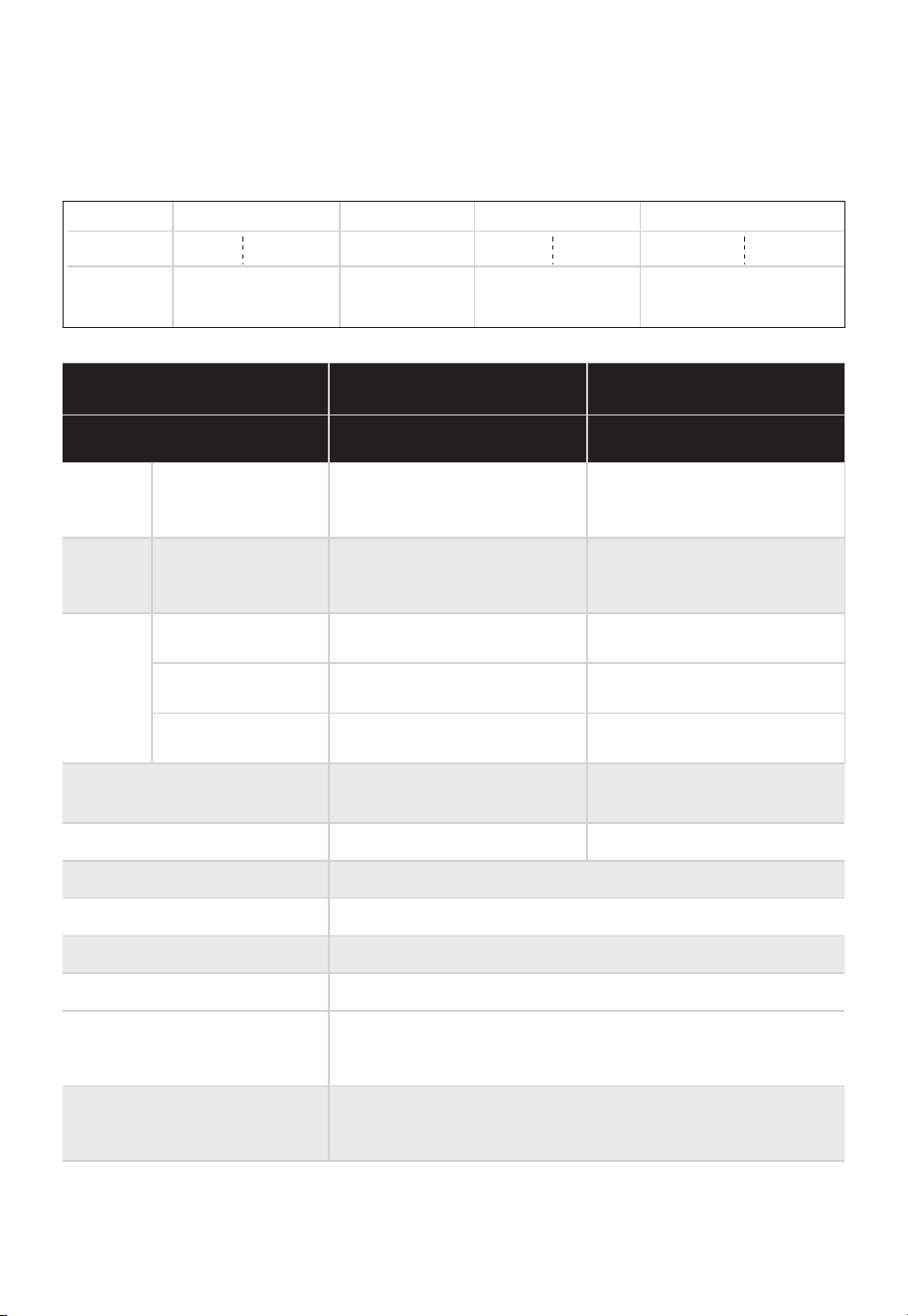
SPECIFICATIONS
Nature Gas Model
Propane Gas Model
Heat
Capacity
(Input)
Natural Gas,
Propane
Gas
UEF
(for NG &
LP)
MGWH150ISNN
MGWH150ISPN
MGWH199ISNN
MGWH199ISPN
Uniform
Energy
Factor
Flow
Rate
(DHW)
37°F (20 °C)
Temp Rise
47°F (26 °C)
Temp Rise
67°F (37 °C)
Temp Rise
Dimensions
Weight
Installation Type
Venting Type
Ignition
Water Pressure
Natural Gas Supply
Pressure (from source)
Propane Gas Supply
Pressure (from source)
24000-150000B
TU/H
0.81
6.6
5.2
3.7
0.81
8.6
6.8
4.8
23000-199000B
TU/H
22.2x14x5.9in
(565*355*150mm)
31.3
lbs(14.2kg)
Indoor
24.7x16.3x7.6in
(627*413*192mm)
39.2lbs(17.8kg)
Forced Draft Direct Vent
Electronic Ignition
15-150 PSI
3.5in.WC-10.5in WC (870Pa~2610Pa)
8in.WC-13in WC (1990Pa-3230Pa)
Note:Pls check the model on the brand, the explanation of the model have been list
below.
MGWH 199 IX N P
Reated power
N: Natural Gas
P:Propane
P:Pump mode
N:No pump
13
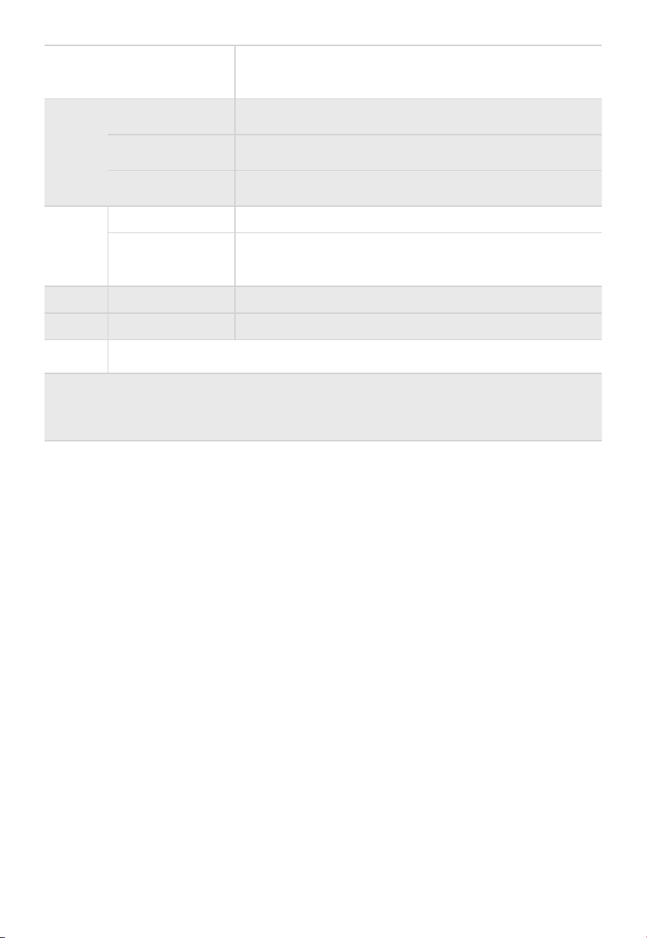
Con-
nection
Sizes
Cold Water
Inlet
Hot Water
Outlet
Gas Inlet
3/4NPT
3/4NPT
3/4NPT
Power
Supply
Main Supply
Maximum
Power
Consumption
Casing
Heat Exchangers
Materi-
als
Venting
Safety Devices
120V,60Hz
180W
SPCC
Copper
3inch,stainless steel
• Water Temperature High Limit Switch (185°F / 85°C)
• Freeze Protection Ceramic Heater
(Turns on at 41°F / 5°C & Turns off at 59°F / 15°C)
Minimum Flow Rate 0.5GPM
(1.9
L/min)
14
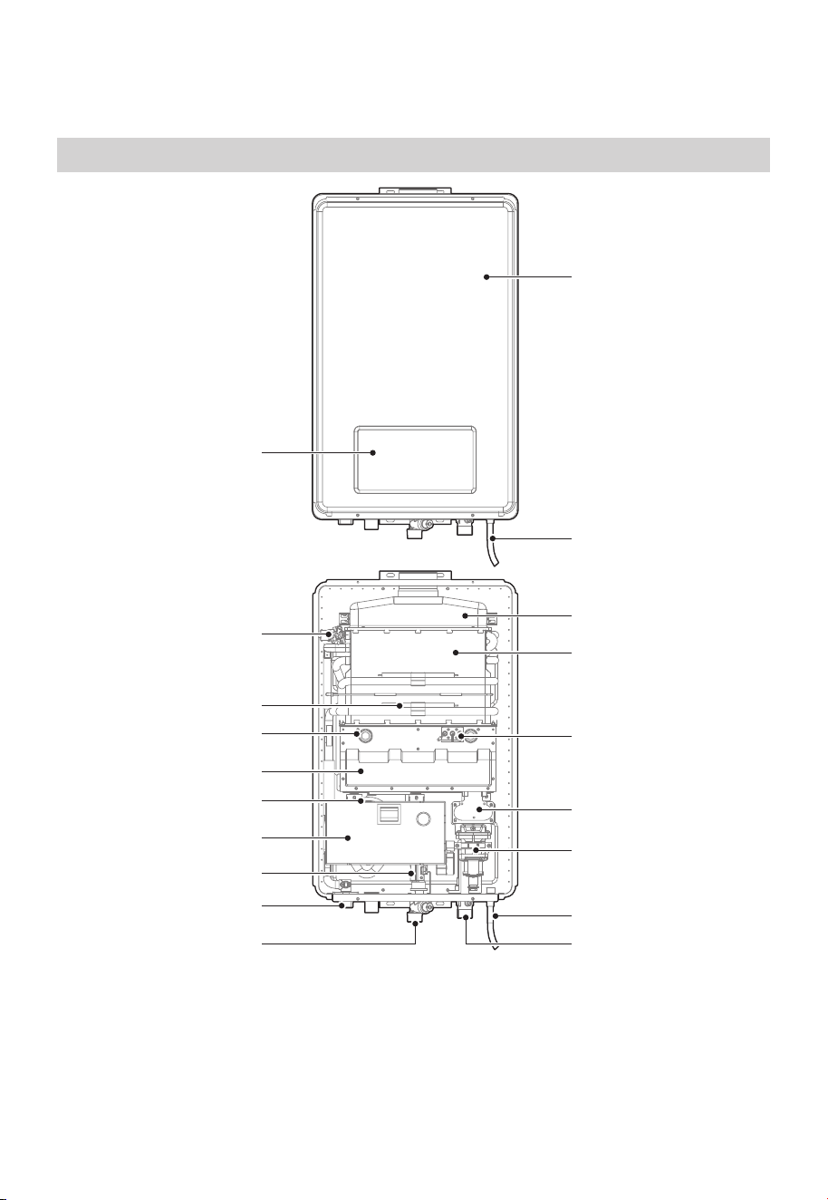
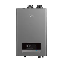
Product
PRODUCT OVERVIEW
Temperature limiter
Cold Water Inlet
Water Flow Sensor
PCB
Hot water outlet
Blower
Combustion Chamber
Flame Window
Anti-frozen Heater
Screen
Flue Hood
Heat Exchanger
Power Cable
Gas Inlet
Gas Valve
Gas Manifold
Ignition Electrode
Face Shell
Power Cable
JSQ40-20VHS
15
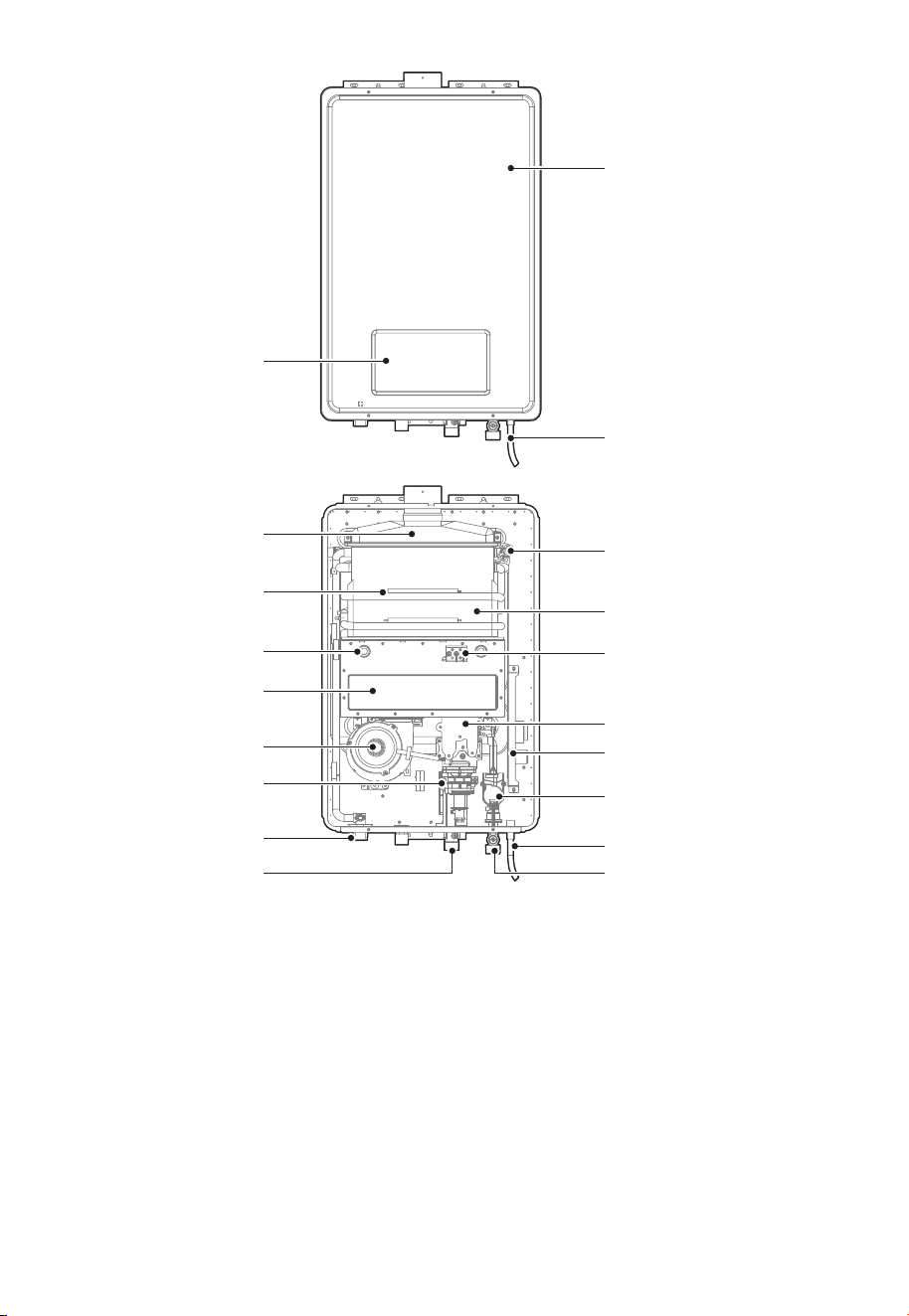
Flue Hood
Gas Inlet
Hot Water Outlet
Gas Valve
Blower
Combustion Chamber
Flame Window
Anti-frozen Heater
Screen
Temperature Limiter
Heat Exchanger
Cold Water Inlet
Water Flow Sensor
Power Cable
Gas Manifold
Ignition Electrode
PCB
Face Shell
Power Cable
JSQ52-26VHS
16
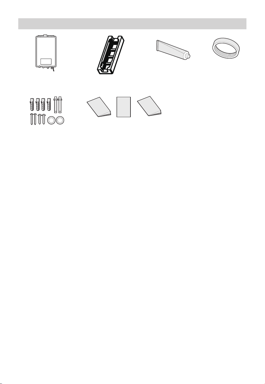
Fastener
Packet x 1
Part List
Tankless Gas
Water Heater x 1
Styrofoam Packing
Materials x 2
Silicone x1 Piece Sealing Gasket
17
Manual x 1
Warranty card x 1
1:1 Installatior
Drawing x 1
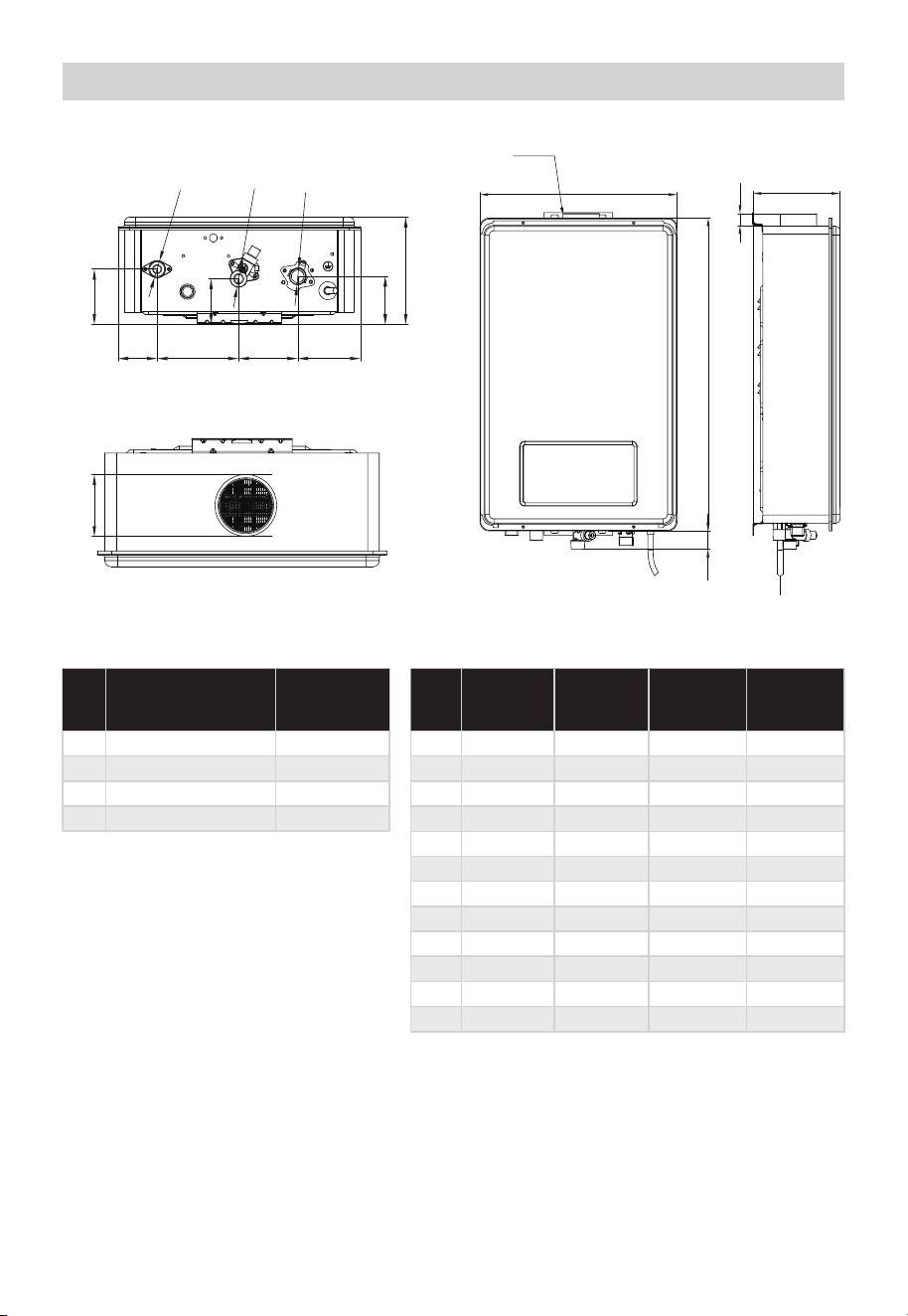
Dimension
Appliance Dimensions
ltem Bottom
View
Front
View
Side
View
Top
View
1
2
3
4
6
7
8
9
10
11
/
/
/
595 mm
375 mm
34 mm
/
/
/
/
/
/
/ /
/ /
/
/
/
166 mm
5 / /
/
/
/
/
/
23 mm
12 /
/
/
/
/
/
/
/
/
/
/
/
R=69 mm
Appliance Components
Description SizeNo.
A
B
C
D
Flue Hood 69 mm
NPT 3/4 in
NPT 3/4 in
NPT 3/4 in
Hot Water Outlet
Cold Water Inlet
Gas Inlet
A
Model: MGWH150ISNN & MGWH150ISPN
Side ViewFront View
2
1
4
3
11
Bottom View
B
C
D
4
6 98
512
10
71
7
Top View
166 mm
86 mm
61 mm
126 mm
92 mm
97 mm
75 mm
18
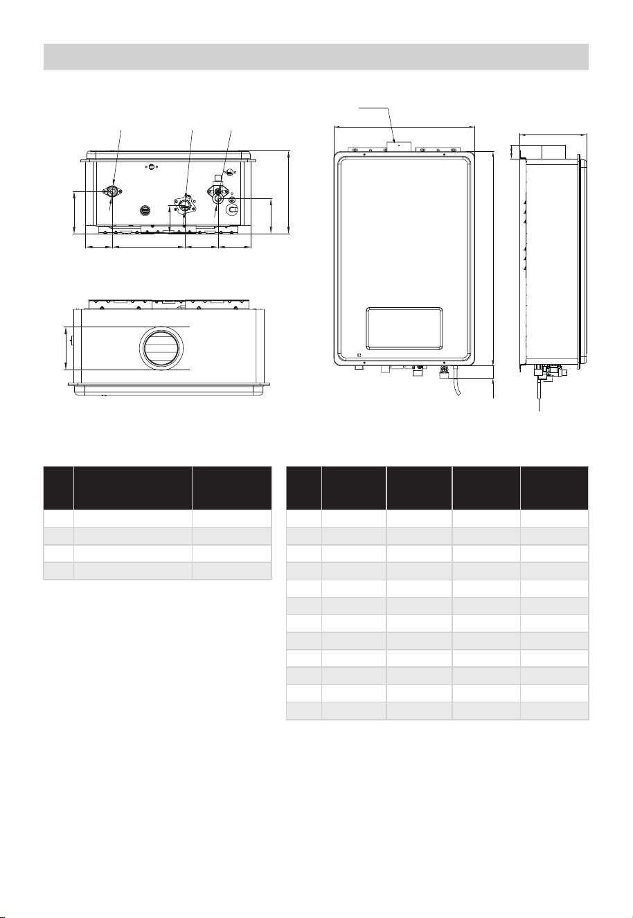
Dimension
Appliance Dimensions
ltem Bottom
View
Front
View
Side
View
Top
View
1
2
3
4
6
7
8
9
10
11
/
/
/
627 mm
413 mm
36 mm
/
/
/
/
/
/
/ /
/ /
/
/
/
166 mm
5 / /
/
/
/
/
/
43 mm
12 /
/
/
/
/
/
/
/
/
/
/
/
R=69 mm
Appliance Components
Description SizeNo.
A
B
C
D
Flue Hood 69 mm
NPT 3/4 in
NPT 3/4 in
NPT 3/4 in
Hot Water Outlet
Cold Water Inlet
Gas Inlet
Model: MGWH199ISNN & MGWH199ISPN
Side ViewFront View
Bottom View
12
Top View
4
10
9
9
5 6 7 8
B
C
D
2
1
3
A
11
195 mm
62 mm
172 mm
78 mm
78 mm
67 mm
83 mm
4
19
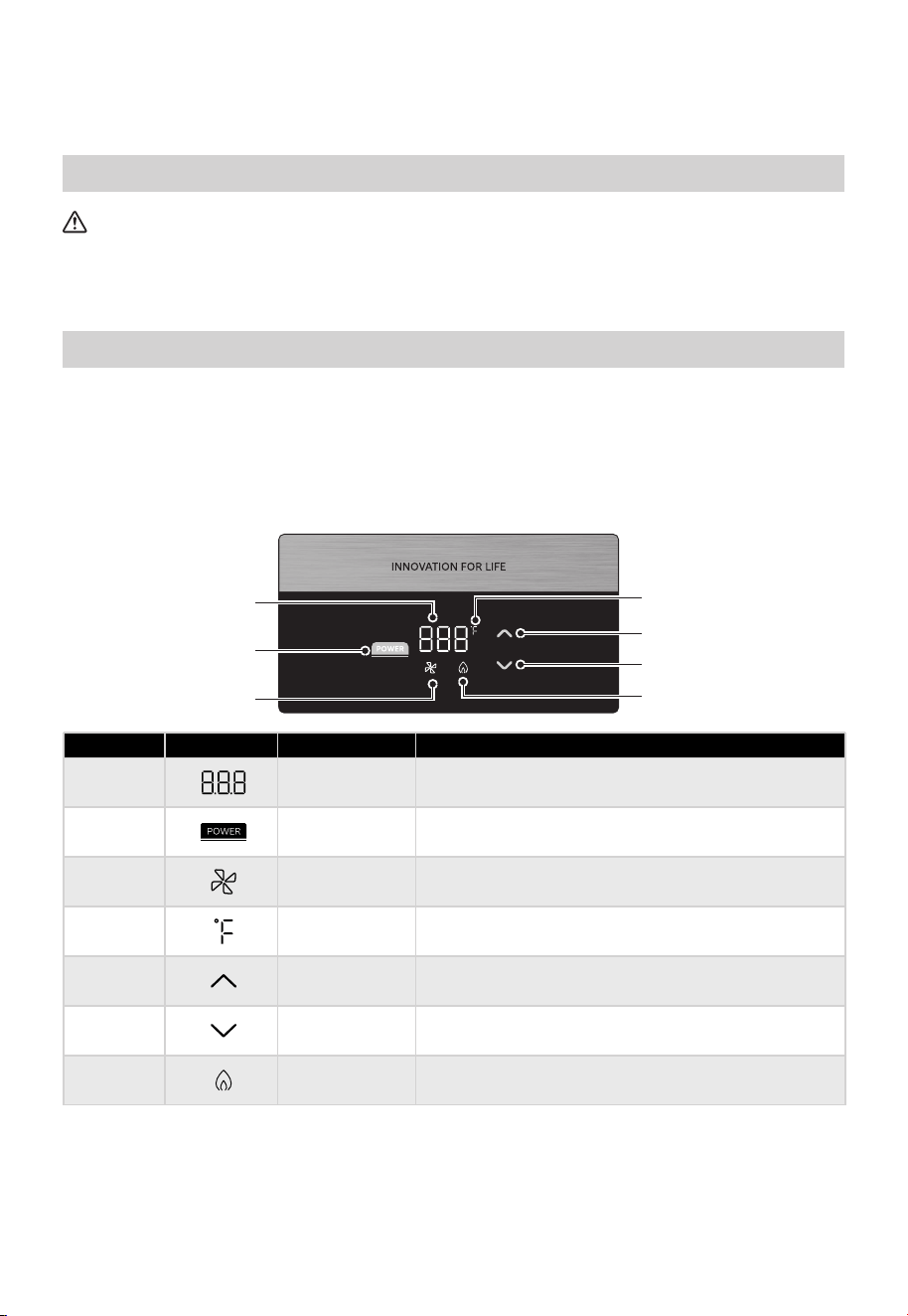
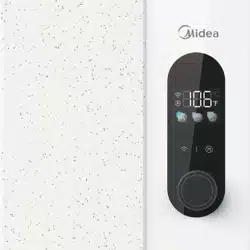
POWER
QUICK START GUIDE
1.
2.
3.
4.
5.
Insert the power supply plug and switch on the power.
Turn on the gas switch.
Open the water inlet valve before ignition
Turn on the hot water faucet. Observe the flame from the screen.
Turn off the hot water faucet
CAUTION
Before first use
Trial running and quick start
Before first using,a trial running should be carried out by authorized professionals.
Before using,please make sure the gas water heater is installed properly.
Power
Power ON/OFF
5
2
Up
6 Down
1 Temperature Displays temperature of the water.
4 Temperature Displays the temperature in Fahrenheit.
7 Flame
Indicates flame signal is detected.
3 Blower Indicates blower is operating.
• Increase temperature setting.
• Decrease temperature setting.
No. Symbol Description Function
3
2
1
5
4
6
7
20
PRODUCT INSTALLATION
WARNING
Save These Instructions
This operation to be performed by an authorized Kings Peak representative or by
specific instruction.
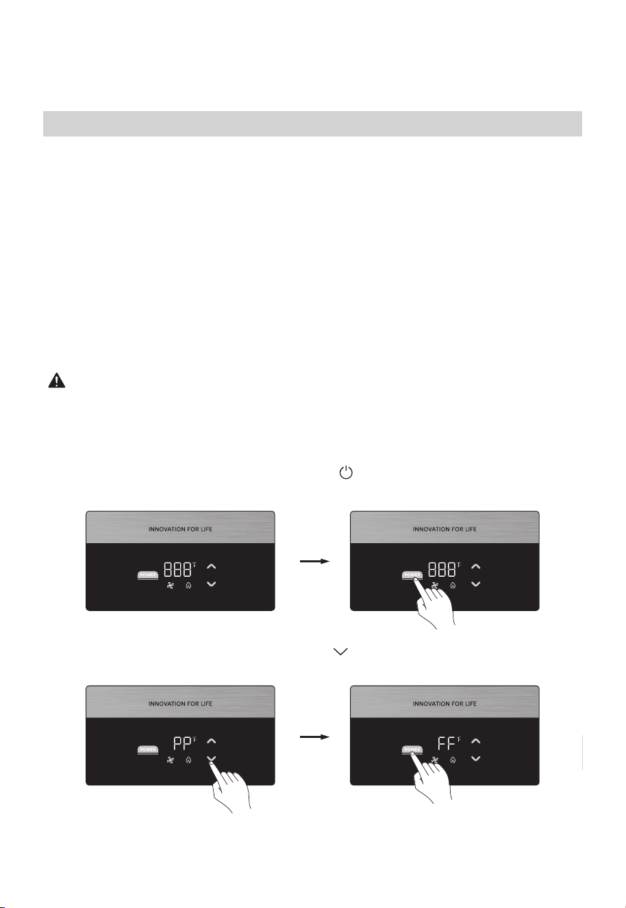
To change program data:
Step 1: Connect the power supply.
Step 2: Turn off the water heater by pressing the button and wait for more than 10
seconds.
Step 3: Connect the power supplyand press the button for at least 3 seconds until PP
is displayed on.
The parameter setting of the water heater may need to be adjusted depending on the
altitude of the location it is being installed. Please refer to the table below for the proper
setting based on altitude. This adiustment can be made through the water heater control
panel
Instructions on how to perform this adiustment can be found in the operating
instructions section of this manual. However, this adijustment should only be performed
by a qualified technician. lf this adjustment is not made, or performed incorrectly, it
could cause improper operation of the unit. lmproper operation could cause gas leakage,
fire, and/or an explosion that can put you at risk of personal injury or death.
Altitude Adjustment:
This water heater must be installed in accordance with these instructions, local codes,
utility company requirements, and/or in the absence of local codes, use the latest edition
of the American National Standard/National Fuel Gas Code.
POWER
POWER
POWER
POWER
21
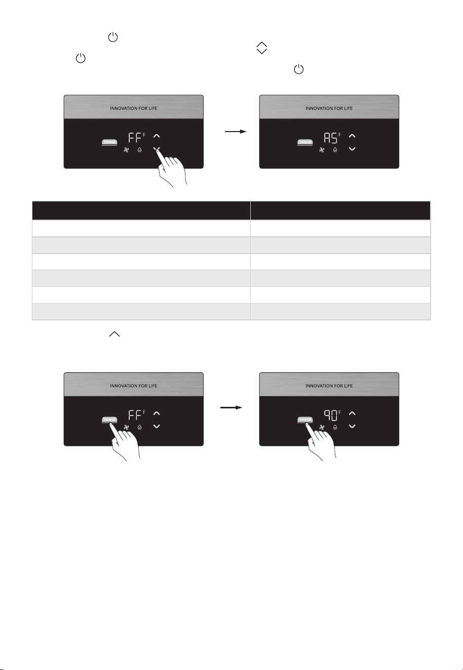
Step4: Press the button, and then FF will displayon the screen. The machine has
entered into the parameter setting mode. Use the buttonsto selectthe AS option.
Press the button to enter AS mode. Scroll through the parameter codes to choose the
Altitude setting based on operating altitude and press the button to confirm the
choice.
Step 5: Press the key continuously until the “qu” option appears, then press the
power to save and confirm the new operating parameters. The appliance will enter the
normal customer operating mode.
POWER
POWER
POWER
POWER
Altitude AS
0-2000 ft 00
012001-3000 ft
4001-5000 ft
3001-4000 ft 02
03
6001-7000 ft
5001-6000 ft 04
05
22

Proper operation of the water heater requires air for combustion and ventilation.
Provisions for combustion and ventilation air must comply with referenced codes and
standards.
• Installation distances may vary by local code. It is the installer’s responsibility to verify
installation requirements.
• Make sure before installation that the gas type you will use is the same type as
displayed on the appliance’s data plate.
• The water heater unit should be installed by professionals. Improper installation may
cause failure or dangerous conditions such as gas leaking or explosion.
• Natural Gas water heaters cannot be installed in an UN-VENTED bathroom, bedroom,
basement, living room, closet, outdoor, stairway, or near an exit area. If installed near
an exit area, it must be at least 16.5’ feet or more away from the exit.
• Vent pipe should extend from the wall at least two (2”) inches. The terminal must be at
least 1.64’ feet away from obstruction and must be well vented.
• Vent pipe should slope 2° (1/4” inch vertical for every one (1’) foot horizontal)
downward, to avoid condensing water and protect from rain entering.
• Vent pipe should avoid direct, strong wind because the downdraft will cause
malfunction of the unit.
• The water heater should be installed far from any blockage and with plenty of space
for installation and maintenance. Adequate clearances for servicing must be provided.
• The water heater should not be installed in the same room with a gas stove.
• When determining the floor clearance, a clearance of six (6”) inches must be
maintained between the vent pipe and combustible material. A side wall clearance of
six (6“) inches and a top clearance of 12” inches must be maintained.
• The vent pipe canbe up to 32’ feet in length with one elbow.
• The power outlet serving this water heater should be grounded properly with a GFCI
circuit protector.
• The water heater should not be located in an area where leakage of the heat exchanger
or connections will result in damage to the area adjacent to it or to lower floors of the
structure. When such areas cannot be avoided it is recommended that a suitable catch
pan, adequately drained, must be installed under the water heater. The pan must not
restrict combustion airflow.
• The water heater should be installed as close as practical to the vent termination to
minimize vent length and the number of elbows required for venting.
• A gas-fired water heater or any other appliance should not be installed in a space
where liquids which give off flammable vapors are to be used or stored. Such liquids
include gasoline, propane gas (butane or propane), paint, adhesives, thinners, solvents,
or removers.
• The water heater should be installed far from other heat sources, flammable, and
dangerous materials. Because of natural air movement in a room or other enclosed
space, flammable vapors can be carried some distance from where their liquids are
being used or stored. The open flame of the water heater's main burner can gnite these
vapors causing an explosion or fire which may result in severe burns, property damage,
or even death.
• Raising the installation height of the water heater will reduce, but not eliminate the
possibility of lighting the vapor of any flammable liquids which may be improperly
stored or accidentally spilled.
• If the water heater is installed in a garage, it should be installed so that the direct
ignition system and main burner are no less than 18” inches above the garage floor.
• Hot and cold-water lines should be insulated to conserve water and energy.
• The water heater must be located so that it is not subject to physical damage, for
example, by moving vehicles, area flooding, etc.
Installing the Water Heater - Indoor Location Only
23
WARNING
Combustible construction refers to adjacent walls and ceilings and should not be
confused with combustible or flammable products and materials. Combustible and/or
flammable products and materials should never be stored in the vicinity of this or any
gas appliance.
А confined space is one having а volume of less than 50 cubic feet per 1,000 BTU/Hr of
the aggregate input of all appliances within that space.
The air must be supplied through two permanent openings of equal area. One is to be
located within 12” inches above the floor and the other is to be located within 12” inches
below the ceiling.
The minimum net free area of each opening must not be less than one square inch per
1,000 BTU/Hr of the total input rating of all the appliances in the enclosure (but not less
than 100 square inches) if each opening communicates with other unconfined areas
inside the building.
Buildings of unusually tight construction shall have combustion and ventilation air
supplied from outdoors, or a freely ventilated attic or crawl space.
If air is supplied from outdoors, directly, or through vertical ducts, there must be two
openings located as specified above and each must have a minimum net free area of not
less than one square inch per 4,000 BTU/Hr of the total input rating of all the appliances
in the enclosure.
If horizontal ducts are used to communicate with the outdoors, each opening must have
a minimum net free area of not less than one square inch per 2,000 BTU/Hr of the total
input rating of all the appliances in the enclosure. If ducts are used, the minimum
dimensions of rectangular air ducts shall not be less than four (4”) inches.
• For other than а direct vent installation, the appliance must be located as close as
possible to а chimney or gas vent.
• DO NOT install water heaters in locations subject to vibrations or on the road use.
• DO NOT install water heaters in Recreational Vehicles, Mobile Homes, Boats, and other
Watercraft.
• DO NOT install the water heater near vents for heating or cooling. А minimum of four
(4’) feet should be maintained.
• If the clearances stated on the Instruction/Warning Label (located on the front panel of
the heater) differ, install the water heater according to the clearances stated in this
manual.
Combustion and Ventilation Air
Air Openings
Min 200 sp.ln
Min.4”
24
Corrosive Atmospheres
If the water heater is installed in an unconfined space within a building of conventional
frame, masonry, or metal construction, infiltration air is normally adequate for proper
combustion and ventilation. If the water heater is installed in a confined space, provisions
for combustion and ventilation air must be made.
The air in beauty shops, dry cleaning establishments, photo processing labs, and storage
areas for liquid and powdered bleaches or swimming pool chemicals often contain
halogenated hydrocarbons.
An air supply containing halogenated hydrocarbons may be safe to breathe, but when it
passes through a gas flame, corrosive elements are released that will shorten the life of
any gas burning appliance.
Propellants from common spray cans or gas leaks from A/C and refrigeration equipment
are highly corrosive after passing through a flame.
The water heater warranty is voided when failure of the water heater is due to operation
in a corrosive atmosphere.
NOTICE
If the duct openings which supply combustion and ventilation air are to be covered with
a protective screen or grill, the net free area (openings in the material) of the covering
material must be used in determining the size of the openings. Protective screening for
the openings MUST NOT be smaller than 1/4”inch to prevent clogging by lint or other
debris.
NOTICE
The water heater should not be installed near any air supply containing halogenated
hydrocarbons.
NOTICE
Inspect the water heater for possible damage during shipment. Check the markings on
the rating plate of the water heater to be certain the type of gas supplied corresponds to
the water heater requirements. Verify that all included parts are present (see below).
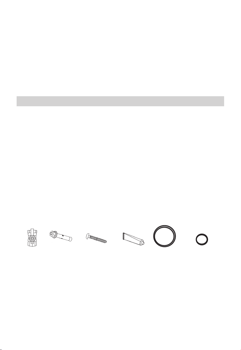
Inspect the Water Heater And Packaging
Manual Gas
Appliance
Shut-off
x1 Piece
Expansion
Screw
x2 Pieces
Wood Screw +
Plastic Expansion
Anchors
x4 Pieces
Silicone
x1 Piece
Water Inlet +
Outlet Rubber
Gaskets
x2 Pieces
Exhaust Vent
Rubber Gasket
x1 Piece
25
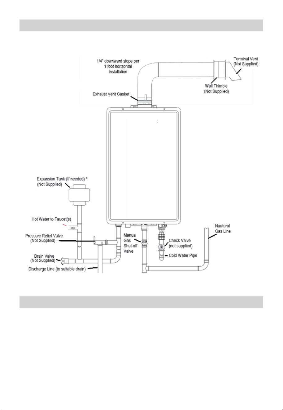
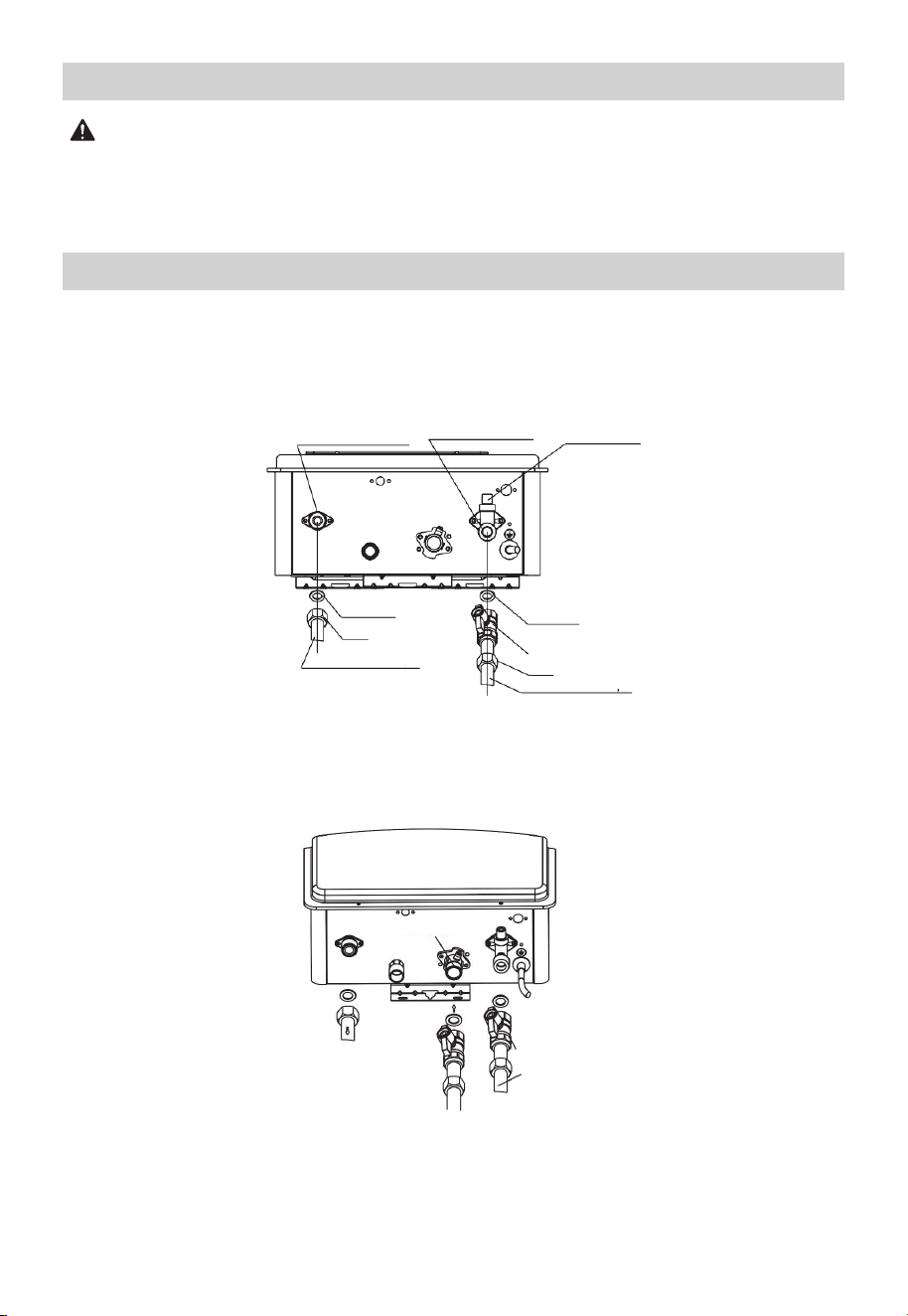
Installing the Water Heater
Typical Installation*
Model: MGWH199ISNN
Water Supply Connections
Plumbing should be carried out by a qualified plumber in accordance with local codes.
Use approved plumbing materials and tools only.
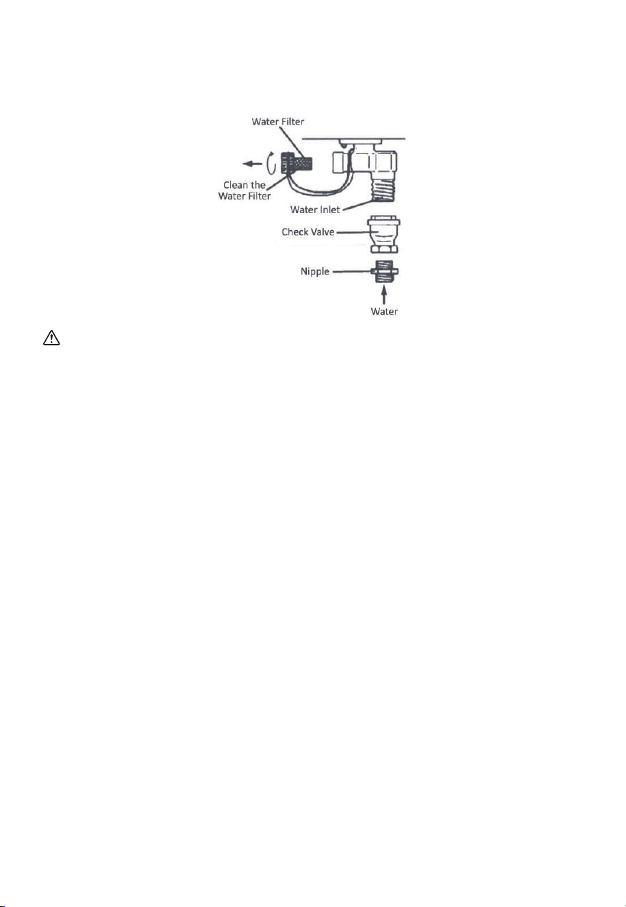
Install a check valve between the water heater and the water shutoff valve. (See
illustration below). To conserve energy and to prevent freezing, insulate both cold and
hot water supply lines. DO NOT cover the drain valves.
Install a water shutoff valve near the inlet of the water heater for service and draining
purposes. Before connecting the water supply pipe to the water heater, open the shutoff
valve, and clean out sand, debris, air, caulking material, etc. inside the pipe. Connect to
the water inlet, then check water flow. Close the shutoff valve and clean the water filter.
*Some Items may not apply
26
CAUTION
This water heater must only be used with the following water supply system conditions:
• With clean, potable water, free of corrosive chemicals, sand, dirt, or other
contaminates.
• Inlet water temperatures above 32° F, but not to exceed 90° F.
• Free of lime and scale deposits. See Page 29 for acceptable Water Quality guidelines.
• Water quality conditions outside of these parameters may void product warranty.
• DO NOT reverse the hot and cold-water connections. The water heater will not
operate.
To ensure proper operation of the water heater, the following water pressure guidelines
should be followed:
• Operation of the water heater requires the minimum water pressure of 14 PSI and a
minimum water flow rate of 0.8 GPM .
• Additional water pressure is required for long pipe runs and outlet fitting(s) water
pressure drops.
• To maintain proper performance, ensure sufficient water supply pressure. The Required
Water Pressure = Min. Operating Water Pressure (14 PSI) + Pipe Pressure Loss +
Faucet and Shower Pressure Loss + Safety Margin (more than 5 PSI).
• To supply hot water to upper floors, additional water pressure (0.44 PSl/ft) must be
ensured. The measurement should be calculated by the distance between the water
inlet of the water heater (ground level) to the hot water faucet (upper floor level).
• Well water systems should be set at a range of 50-60 PSI.
• When the water is supplied from a water supply tank, the height of the tank and the
diameter of the pipes and their relation to water pressure should be taken into consid-
eration. Gravity water pressure is not recommended.
If a water heater is installed in a closed water supply system, such as one having a
backflow preventer in the cold-water supply line, means shall be provided to control
thermal expansion. Contact the water supplier or local plumbing inspector on how to
control this situation.
Do not apply heat to the HOT or COLD water connections. Any heat applied to the water
supply fittings will permanently damage the internal components of the water heater.
Important
27
If the water flow resistance of a shower head is too high, the burner in the water heater
will fail to ignite.
Keep shower heads clean from debris that could cause additional pressure drop.
NOTICE
• Connections between the water heater and point(s) of use should be as short and
direct as possible.
• DO NOT use lead or non-approved plastic pipe.
• To conserve energy and minimize heat loss, insulation of the hot water piping is
recommended.
Regarding the Hot Water Outlet
If using mixing valves on the outlet, choose one which prevents cold water pressure from
overcoming hot water line pressure.
DO NOT use pipes with smaller diameters than the water supply connection of the water
heater.
Be sure to connect the water inlet and the hot water outlet as shown on the water heater.
If reversed, the water heater will not function.
Installation of unions or flexible copper connections are recommended on the HOT and
COLD water lines so that the water heater may disconnect easily for servicing if
necessary.
NOTICE
The flow rate of hot water may vary when more than two outlets (faucets, appliances,
fixtures, etc) are being used simultaneously.
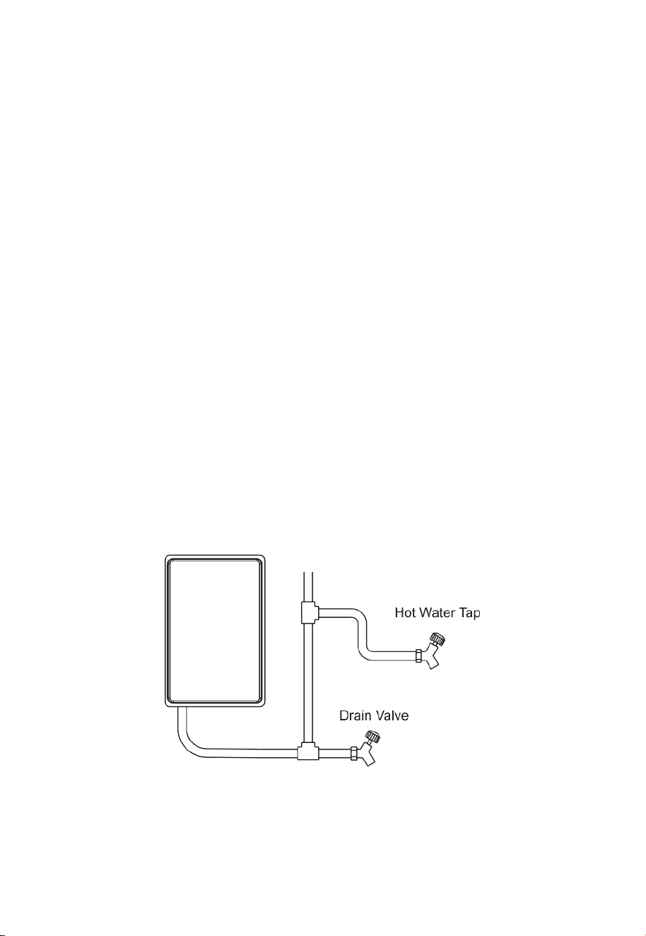
NOTICE
The pipes MUST be completely drainable. If the hot water faucets are located at a point
higher than the water heater, place a drain valve at the lowest point (see diagram to the
below).
NOTICE
28
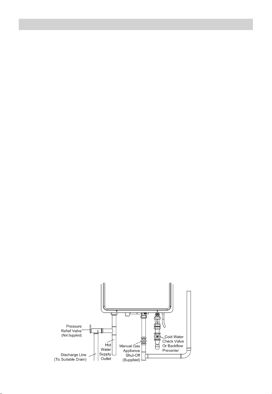
Relief Valve
A new pressure relief valve (not supplied), complying with the Standard for relief Valves
and Automatic Gas Shut-Off Devices for Hot Water Supply Systems, ANSI Z21.22, must
be installed at the hot water outlet connection of the water heater at the time of
installation. Local codes shall govern the installation of relief valves.
For safe operation of the water heater, be sure that:
• The pressure rating of the relief valve must not exceed 150 PSI, the maximum working
pressure of the water heater as marked on the rating plate.
• The BTU/Hr rating of the relief valve must equal or exceed the BTU/Hr input of the
water heater as marked on its rating plate.
• No valve of any type should be installed between the relief valve and the water heater.
• Discharge from the relief valve should be piped to a suitable drain to eliminate
potential water damage. Piping used should be of a type approved for the distribution
of hot water.
• HOT and COLD water lines should be insulated up to the water heater, but not
covering any connections.
• The discharge line must be NO SMALLER than the outlet of the valve and must pitch
downward to allow complete drainage (by gravity) of the relief valve and discharge
line.
• The end of the discharge line should not be threaded or concealed and should be
protected from freezing.
• No valve of any type, restriction, or reducer coupling should be installed in discharge
line.
The diagram below illustrates a pressure only relief valve. If local codes require a
combination temperature and pressure relief valve be installed, an extension piece may
be needed.
Local codes govern the installation of relief valves. If local codes require that a
temperature and pressure relief valve should be installed the manufacturer recommends
a type 40XL Watts T&P relief valve or an equivalent model be used.
Manual operation of relief valves should be performed at least once a year. Turn off the
electrical power and manual gas appliance shutoff valve. Lift and release lever on the
relief valve and check the manual operation of the relief valve.
You should take precautions to avoid contact with the hot water coming out of the relief
valve and to prevent water damage.
If the relief valve on the system discharges periodically, this may be due to thermal
expansion in a closed water supply system. Contact the water supplier or local plumbing
inspector on how to correct this situation. Do not plug the relief valve.
NOTICE
29
WARNING
Do not attempt to convert this water heater for use with a different type of gas other
than the type shown on the rating plate. Such conversion could result in hazardous
operating conditions.
Only have a professional connect the gas pipe.
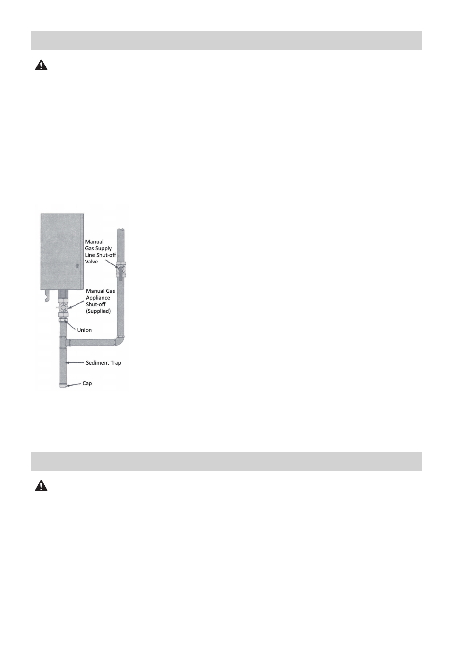
The supplied manual gas appliance shut-off valve must be installed at the gas connection
of the water heater at the time of installation.
The branch gas supply line to the water heater should be a clean black steel pipe or
other approved gas piping material.
A ground joint union or ANSI design certified semi-rigid or flexible gas appliance
connector should be installed in the gas line close to the water heater.
The National Fuel Gas Code (NFGC) mandates a manual gas shut-off valve: See NFGC
for complete instructions.
A sediment trap should be installed at the bottom of the gas line.
The inlet gas pressure to the water heater must not exceed 10.5”
wc.
For purposes of input adjustment, the minimum inlet gas
pressure (with main burner on) is shown on the water heater
rating plate. If high or low gas pressures are present, contact your
gas supplier for correction.
The water heater and its individual manual gas appliance shut-off
valve must be disconnected from the gas supply piping system
during any pressure testing of that system at test pressures in
excess of V2 PSI (14” wc or 3.5 kPa). The water heater must be
isolated from the gas supply piping system by closing its
individual manual shut-off valve during any pressure testing of
the gas supply piping system at test pressures equal to or less
than 1/2. PSI (14” wc or 3.5 kPa).
DO NOT use excessive force (over 31.5 ft lbs.) in tightening the
pipe, particularly if pipe compound is used, as the unit may be
damaged.
The compound used on the threaded joints of the gas piping
must be of the type resistant to the action of natural gas. Use
compound sparingly and use on male threads only.
Gas Supply
WARNING
Never use an open flame to test for gas leaks, as property damage, personal injury, or
death could result. The water heater and its gas connections must be leaktested at
normal operating pressures before it is placed into operation.
• Turn on the gas shut-off valve(s) to the water heater.
• Use a commercial leak detector or soapy water solution to test for leaks at all
connections and fittings.
Bubbles indicate a gas leak that must be corrected.
AII connections should also be leak tested after the water heater is placed into operation.
Leak Testing
30
WARNING
Install a gas pressure regulator in the gas supply line which does not exceed the
maximum supply pressure. DO NOT use an industrial type gas regulator.
The water heater must be isolated from the gas piping system by closing the manual gas
shut-off valve during any pressure testing of the gas supply piping at pressures equal to
or less than 1/2 PSI (14” wc).
WARNING
Use UL approved Category III Stainless Steel vent material only. No other vent material is
permitted. Installer must refer to vent manufacturer's instructions and specifications.
Information on Z-Flex™, an approved venting material, can be found at
www.novaflex.com
The installation of venting must comply with national codes, local codes, and the vent
manufacturer’s instructions. Installer must refer to vent manufacturer's instructions and
specifications. Please visit a local hardware store or online marketplaces to purchase 3”
Category III Stainless Steel Venting for certified installation, such as Z-Flex™ referenced
above.
The water heater must be vented to the outdoors as described in these instructions.
DO NOT connect this water heater to an existing Vent or Chimney, it must be vented
separately from all other appliances.
AII vent components (adapters, pipe, elbows, terminals, etc.) should be UL 1738 Certified
Stainless Steel Venting Material (e.g. AL29-4C).
The specified vent termination must be used. The termination should be a 90° elbow
type with screen.
Use a vent pipe with an antidisconnection structure.
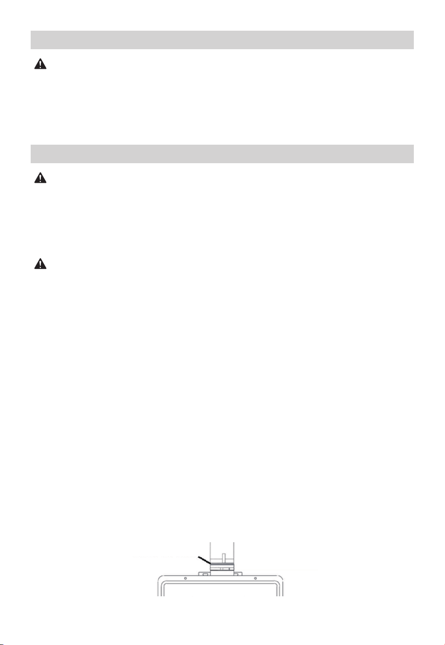
The use of a High Temperature Silicone (500°F) may be required to seal vent
connections. Insert the pipe onto the exhaust vent rubber gasket to start the vent run.
Make sure to completely slide the vent into the collar until make sure the tube contact
with the bottom of gasket. The vent pipe will be sealed by the rubber gasket with the
addition of the silicon provided on both side of rubber gasket to make it fixed well. To
prevent accidental gas exhaust leakage, apply a 1/4” wide bead approximately 1/4” from
the end and another bead against the joint side of the stop bead.
DANGER
Failure to install the vent adapter and properly vent the water heater to the outdoors as
outlined in the VENTING section of this manual will result in unsafe operation of the
water heater causing death, serious injury, explosion, and/or fire. To avoid the risk of fire,
explosion, or asphyxiation from carbon monoxide, NEVER operate the water heater
unless it is properly vented and has adequate air supply for proper operation as outlined
in the VENTING section of this manual.
Pressure Testing the Gas Supply System
Venting
Exhaust Vent Gasket
31
If the vent piping passes through a closed space, wrap the vent pipe with nonflammable
insulation material that is at least 3/4” thick. DO NOT let the insulation material contact
flammable materials. A minimum clearance of six (6”) inches between the vent pipe and
ceiling should be maintained. Follow all local codes.
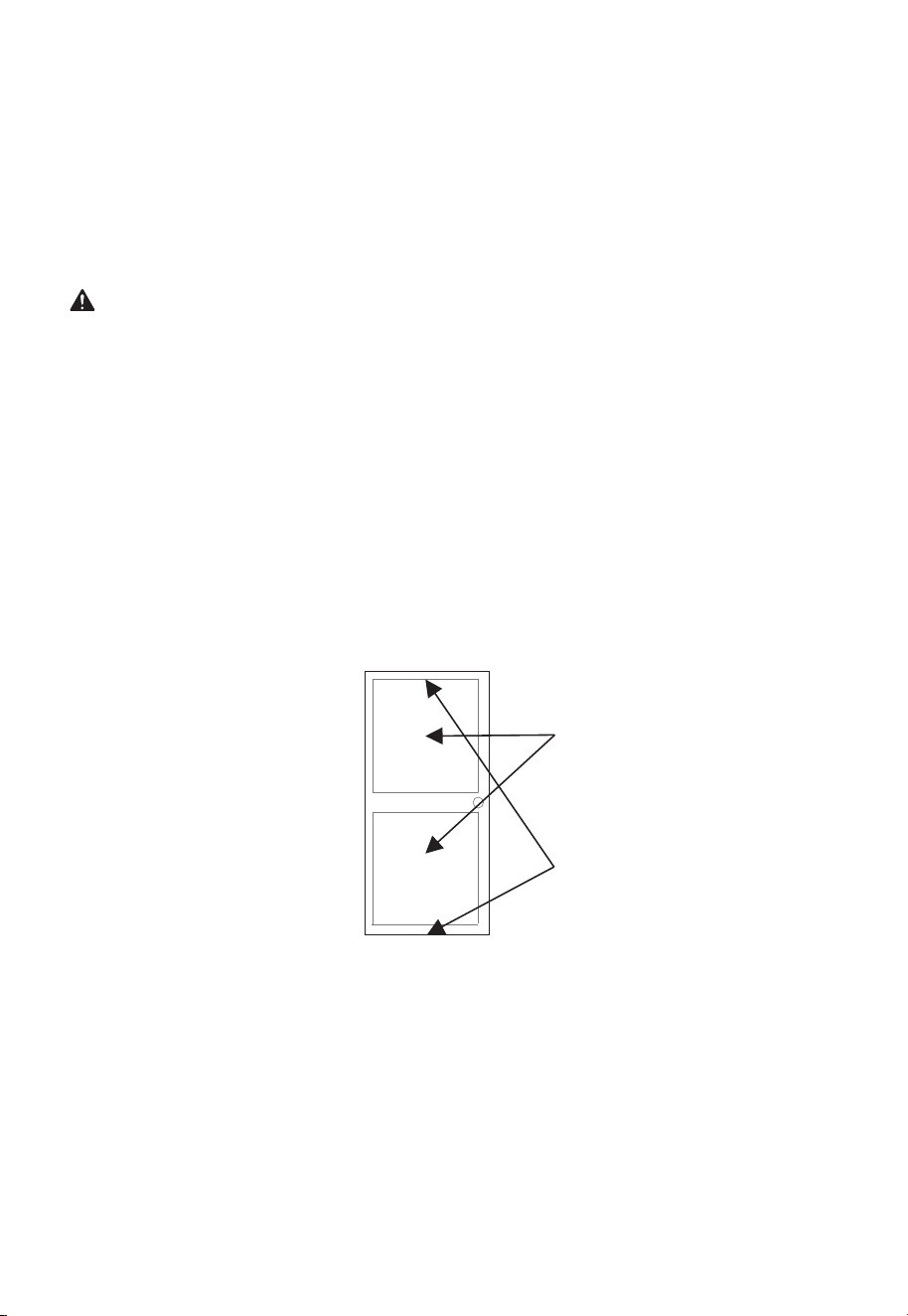
For maintenance and inspection purposes, the following holes are required to be made:
• Two (2) inspection openings that allow access to venting. One of these openings
should be close to where the vent pipe enters the ceiling. The other opening should be
near the vent termination.
• A ventilation hole with a 16 sq. in. opening should be made at least every ten (10’) feet.
Follow vent manufacturer’s installation instructions. The unit can be vented either
horizontally or vertically.
Vent pipe runs must be adequately supported along both horizontal and vertical runs.
The maximum recommended unsupported span is no more than four (4’) feet. Support
isolation hanging bands should be used. DO NOT use wire.
Venting Through Closed Spaces
Vent pipes must be completely insulated with nonflammable material when installed in
alcoves, closets, and garages and must not touch any flammable material.
NOTICE
32
Venting Lengths
The installer must refer to vent manufacturer’s instructions and specifications.
The system will not operate if there is excessive restriction (pressure drop) in the venting
system. A maximum of 32’ feet of vent pipe may be used provided there is only one 90°
elbow in the system. If additional elbows are required: two elbows can be used with 27
feet of vent pipe, and three elbows can be used with 22 feet of vent pipe.
A 90° elbow is equivalent to 5 feet of straight pipe. A 45° elbow is equivalent to 2’ feet
6” inches of straight pipe. The termination elbow does not count as an elbow when
determining total vent lengths.
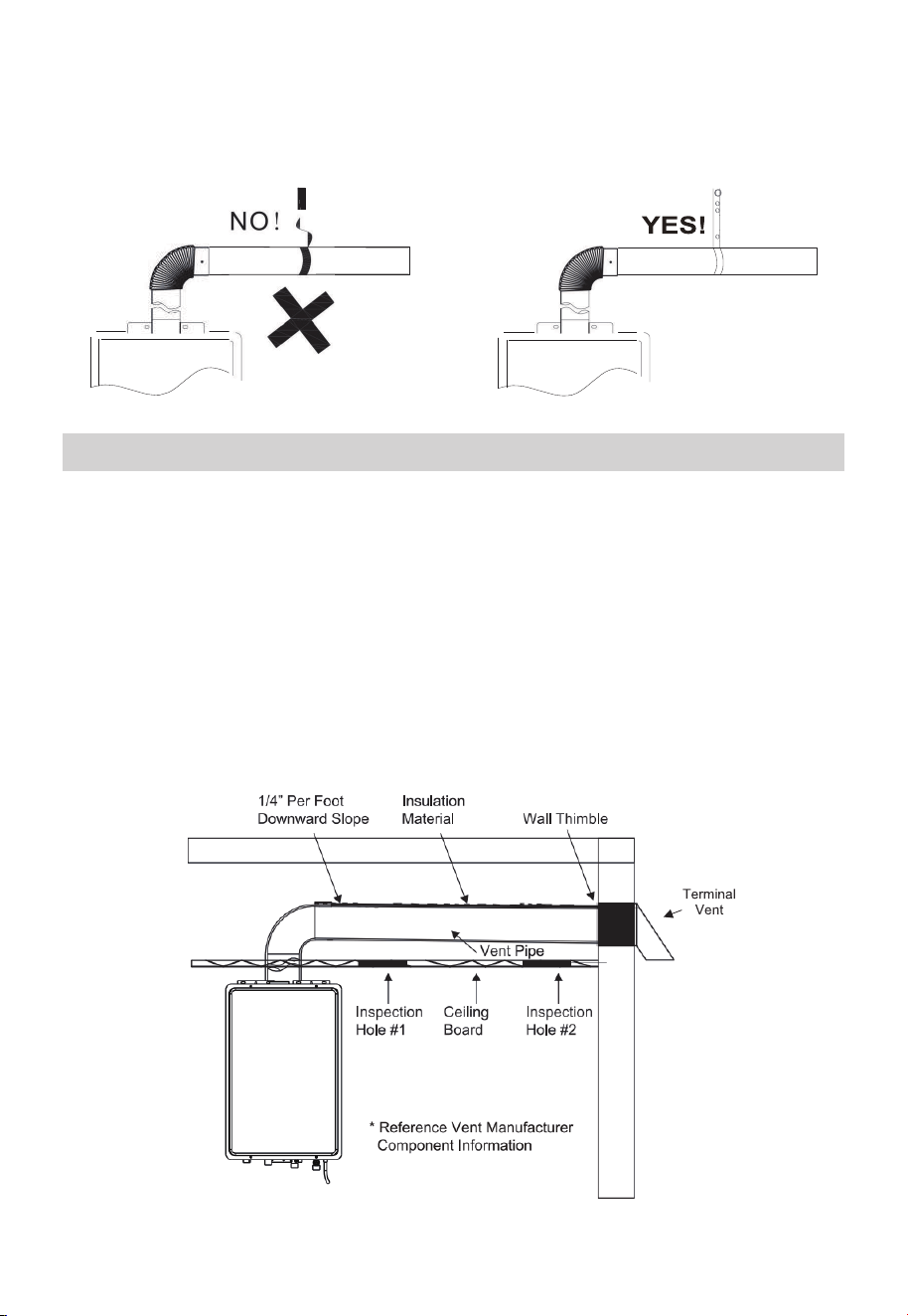
The vent pipe must be installed with a slight downward slope of 1/4” inch per foot of
horizontal run toward the vent terminal (see diagram below). This ensures that any
condensate formed during operation of the unit is evacuated from the water heater.
A 1/4” per foot upward slope is acceptable when it is not possible to vent with a
downward slope; however, a UL approved Category III Stainless Steel condensate trap
MUST be installed at the beginning of the horizontal run.
The venting may be as short as 35”, provided one vent termination is installed to the
outdoors through a sidewall, one 90° elbow is included in the installation, and the wall
thimble is installed.
Maximum Vent Length
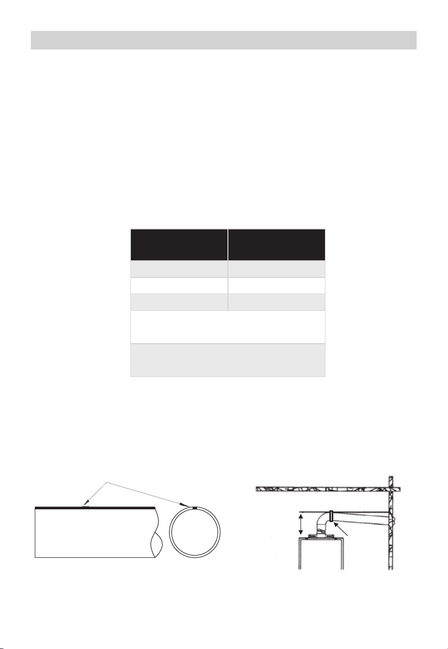
Make sure that the seam of the vent pipe in horizontal runs is toward the top of the
installation (see illustration below on the left).
NOTICE
Number of 90°
elbows (Bends)
Maximum length
of straight pipe
1
2
3
32’
27’
22’
One (1) 90° elbow is equivalent to 5’ feet
(60”) of straight pipe
One (1) 45° elbow is equivalent to 2.5’ feet
(30”) of straight pipe
Vent Seam
1/4 Inch per Foot Downward Slope
Minimum
one (1 ’) foot
Maximum
two (2’) feet
Condensate
trap and
drain (if
needed)
33
In certain conditions, installations in unconditioned space or having long horizontal or
vertical runs may accumulate condensate.
Condensate is known to be acidic; refer to local, state, or federal codes for proper
handling methods.
To prevent condensate from draining back into the water heater, we recommend a
condensate trap and drain to be installed in a horizontal vent section as close as practical
to the water heater vent connection. Not following proper condensate procedures will
void this product’s warranty.
Draining The Condensate
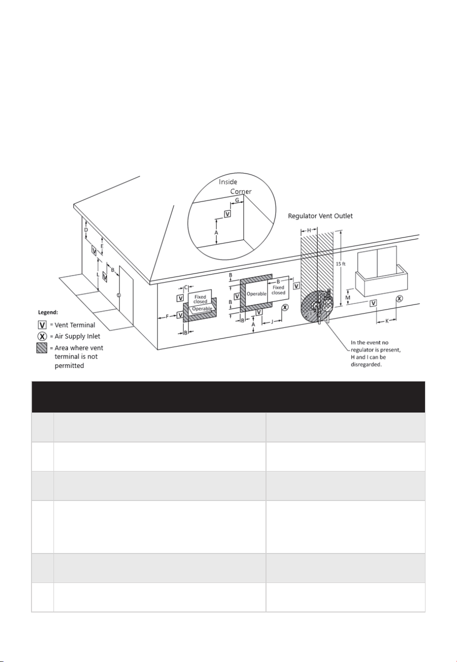
Vent Termination Clearances For Non-direct
Vent Installations
US installations (minimum distances specified in the National Fuel Gas Code, ANSI
Z223.1/NFPA 54, and/or the Natural Gas and Propane Installation Code, CSA B149.1)
A =
Clearance above grade, veranda, porch, deck,
or balcony
12” inches
B =
Clearance to window or door that may be
opened
4 ft (48”) below or to side of
opening. 1 ft (12”) above opening
C = Clearance to permanently closed window *
D =
Vertical clearance to ventilated soffit located
above the terminal within a horizontal
distance of 2 ft (24” inches) from the center
line of the terminal
*
E = Clearance to unventilated soffit *
F = Clearance to outside corner
*
34

The minimum distance from adjacent public walkways, adjacent buildings, openable
windows, and building openings shall not be less than those values specified in the
National Fuel Gas Code, ANSI Z223.1/NFPA 54, and/or the Natural Gas and Propane
Installation Code, CSA B149.1;
Vent termination clearances are in accordance with:
1) current CSA B149.1 Natural Gas and Propane Installation Code.
2) current ANSI Z223.1 / NFPA 54 National Fuel Gas Code.
If locally adopted installation codes specify clearances different than those illustrated
on page 20, then the most stringent clearance shall prevail.
A. Information on preventing blockage by snow; and
B. Information on protecting building materials from degradation by flue gases.
• Avent shall not terminate directly above a sidewalk or paved driveway that is located
between two single family dwellings and serves both dwellings.
• A vent termination is permitted only if veranda, porch, deck, or balcony is fully open on
a minimum of two sides beneath the floor.
* Clearance in accordance with local installation codes and the requirements of the gas
supplier
US installations (minimum distances specified in the National Fuel Gas Code, ANSI
Z223.1/NFPA 54, and/or the Natural Gas and Propane Installation Code, CSA B149.1)
G =
Clearance to inside corner *
H =
Clearance to each side of center line extended
above meter/ regulator assembly
*
I =
Clearance to service regulator vent outlet *
M =
Clearance under veranda, porch deck, or
balcony
*
J =
Clearance to nonmechanical air supply inlet to
building or the combustion air inlet to any
other appliance
4 ft (48”) below or to side of
opening; 1 ft (12”) above opening
K=
Clearance to a mechanical air supply inlet
L=
Clearance above paved sidewalk or paved
driveway located on public property
3 ft (36”) above if within 10 ft
(120”) horizontally
7 ft (84”) for mechanical draft
systems (Category I appliances).
Vents for Category II and IV
appliances cannot be located
above public walkways or other
areas where condensate or
vapor can cause a nuisance or
hazard
35
CAUTION
Follow the vent manufacturer’s installation instructions as design might vary from
manufacturer to manufacturer.
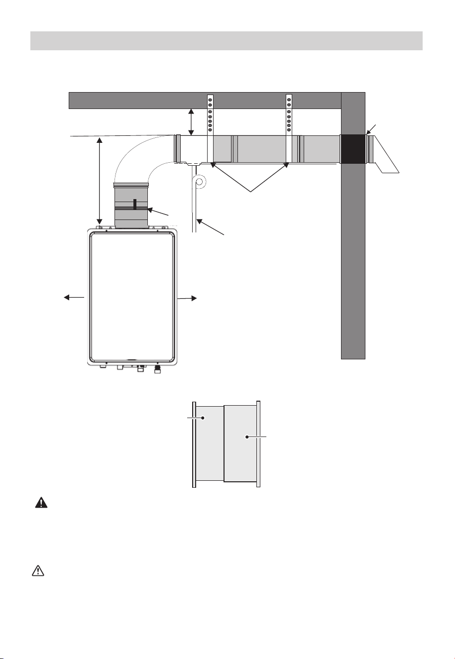
Installing the Water Heater Illustration
WARNING
Use UL approved Category III vent material only. No other vent material is permitted.
Installer must refer to vent manufacturer's instructions and specifications.
Please visit a local hardware store or online marketplaces to purchase UL approved
Category III Stainless Steel Venting for certified installation.
Typical Horizontal Termination
¼ Inch Per Foot Downward Slope Illustrated
TYPICAL WALL THIMBLE INSTALLATION ILLUSTRATION
Six (6”) inch Clearance
Adaptor
Support Hangers
Minimum
one (1’)
foot
Maximum
two (2’)
feet
To drain, dispose of the
condensate in accordance
with local codes
10” inch
space gap
10” inch
space gap
Wall
Thimble
(detailed
on next
page)
Inner Thimble
Section
Outer Thimble
Section
Towards Water Heater
Towards Outside
Terminal Vent
36
CAUTION
Label all wires prior to disconnection when servicing controls. Wiring errors can cause
improper and dangerous operation. Verify correct operation after servicing.
Electrical Connections
Hard Wiring the Electrical Connections
WARNING
Shock hazard line voltage is present. Before servicing the water heater, turn off the
electrical power to the water heater at the main disconnect or circuit breaker. Failure to
do so could result in severe personal injury or death. Additionally, it is recommended to
unplug the power cord from the outlet serving the unit and wait at least ten (10) seconds
after disconnecting before servicing the unit.
WARNING
Field wiring connections and electrical grounding must comply with local codes, or in the
absence of local codes with the latest edition of the National Electrical Code ANSI/NFPA
70.
Powercord
• The electric power supply requirement for this water heater is 120 VAC/60Hz, 2 Amps.
• The water heater comes with a three (3) pin power supply cord. Use only a power
outlet with a ground terminal.
• The installation of an electric leakage breaker (GFCI) is recommended.
• Keep any excess of the power supply cord on the outside of the water heater.
• If local codes require hardwiring, see instructions for “HARDWIRING THE ELECTRICAL
CONNECTIONS” below.
• Wiring should be carried out by a qualified electrician in accordance with local codes.
• The water heater requires 120 VAC/60Hz and should be properly grounded.
• DO NOT connect grounding wire to water pipes, gas pipes, telephone cables, lightning
conductor circuits and to grounding circuits of other equipment that carry a
ground-fault interrupter.
• An ON/OFF switch must be provided and installed for incoming 120 VAC power.
• Wire the water heater exactly as shown below. A wiring diagram is also found inside
the cover panel.
• A green screw is provided in the junction box for grounding connection.
• Connect the live wire to black leg wire and neutral wire to the white neutral wire.
37
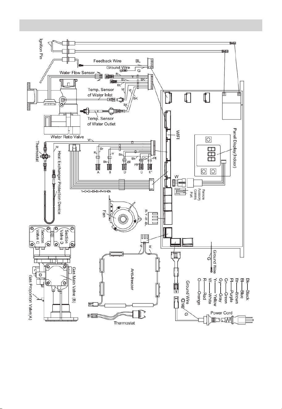
Electric Wiring Diagram
38
Insulation Blankets
Pipe Installation
WARNING
Do not use an insulation blanket with this product.
Utilizing an external insulation blanket will void this product’s warranty.
For increased energy efficiency, please use pipe insulation.
Powercord
Use pressure resistant pipe to connect the inlet and outlet water pipes of the water
heater and the local water pipe (Make sure to place a rubber gasket (supplied) when
connecting). Before connecting the inlet water pipe, flush the inside of the pipe.
Hot And Cold Pipe Insulation
When installing pipe insulation, please install the insulation according to the manufactur-
er’s instructions making sure to insulate all the way to the top of the pipe to the nut. Do
not cover any drain or pressure valve(s).
Outlet Water Pipe
Inlet Water Pipe
Drain Valve
Gasket
Gasket
Nut
Nut
Hot Water Pipe
Check Valve
Cold Water Pipe
Gas Inlet
Check Valve
Inlet Pipe
Cold Water
Hot Water
39
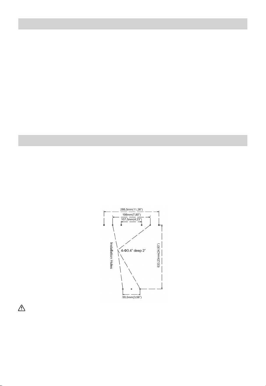
CAUTION
Reinforcement of the wall is required in case the wall is not strong enough to hold the
water heater.
Make sure the location of the water heater allows for easy access and operation. In case
of dry wall or concrete wall, use dry wall anchors or lag bolts.
The water heater requires 120 VAC/ 60Hz. Have a receptacle with ground terminal near
the water heater. The length of the power supply cord is five (5’) feet.
Drill the holes as per the sizes in the figure to the right, put two (2) expansion screws
into the top holes, and two (2) plastic expansion inserts into the bottom holes.
Hang up the water heater unit, tighten the expansion screws, and put two (2) wood
thread screws into the bottom holes.
During Installation of This Water Heater
Mounting the Water Heater
MUST DO
• DO check inlet gas pressure to ensure that it is within the range specified on the rating
plate.
• DO provide adequate air for combustion and ventilation as discussed in this Manual
and the National Gas Code.
• DO maintain proper clearances to combustibles as specified by applicable code.
• DO ensure that the flue terminal location complies with the guidelines found in this
Manual and National Fuel Gas Code.
DO NOT
• DO NOT block or restrict Air Intake Opening located on the back side of the water
heater.
• DO NOT remove the front cover unless necessary and mandatory.
• DO NOT install this product where standing water may occur.
40
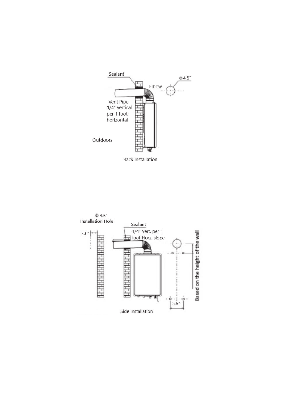
1. Insert the vent pipe through the installation hole in the wall with the terminal sticking out.
2. Connect the elbow to the vent pipe and water heater, moving straight backwards until the
expansion screws go into the holes of the water heater. Screw the nuts tight (pay attention
to the direction of the elbow).
A. Back Installation
1. Aim the holes in the water heater onto the expansion screws, hang it up, and screw the
nuts tightly.
2. Put the vent pipe through the holes in the wall and connect the elbow with the water
heater and vent pipe.
B. Side Installation
Not recommended
Veritcal Installation
41

Installation Check List
A. Water Heater Location
• Installed indoors.
• Close to area of mostly used outlet.
• Protected from freezing temperatures.
• Proper clearance from combustible surfaces observed.
• Sufficient fresh air supply for proper operation of water heater.
• Air supply free of corrosive elements and flammable vapors.
• Provisions made to protect area from water damage.
• Sufficient room to service heater.
• Combustible materials, such as clothing, cleaning materials, rags, etc. clear of the
heater and vent piping.
• Water heater is properly attached to the wall.
B. Water Supply
• Water supply has sufficient pressure.
• Water quality is within operating parameters as outlined on Page 29.
• Air purged from water heater and piping.
• Water connections tight and free of leaks.
• Water filter is clean and in place.
• Materials used are as instructed in this manual.
• Water pipes are insulated.
C. Relief Valve
• Pressure Relief Valve properly installed and discharge line run to open drain.
• Discharge line protected from freezing.
D. Gas Supply
• Gas type matches rating plate.
• Gas supply pressure is sufficient for the water heater.
• Gas line equipped with shut-off valve, union, and sediment trap.
• Approved pipe joint compound used.
• Commercial leak detector or soap and water solution used to check all connections
and fittings for possible gas leak.
• Gas company inspected installation (if required).
E. Electrical Wiring
• Voltage matches rating plate.
• Water heater is properly grounded.
• Wiring meets all local codes.
• GFCI Protection where required.
42
For your Safety Before Using the Water Heater
WARNING
If you do not follow these instructions exactly, а fire or explosion may result in causing
property damage, personal injury, or loss of life.
A. This water heater does not have a pilot. It is equipped with an ignition device which
automatically lights the burner. Do not try to light the burner by hand.
B. BEFORE OPERATING smell all around the water heater area for gas. Be sure to smell
next to the floor because some gas is heavier than air and will settle on the floor. Test
all connections with a commercial leak detector or soapy water.
C. Use only your hand to push in or turn the gas control knob. Never use tools. If the
knob will not push in or turn by hand, don't try to repair it, call a qualified service
technician. Force or attempted repair may result in a fire or explosion.
• Immediately call your gas supplier from a neighbor’s phone. Follow the gas supplier’s
instructions.
• If you cannot reach your gas supplier or fire department.
What To Do If You Smell Gas
OPERATION INSTRUCTIONS
Lighting the Water Heater
Before operating this water heater, be sure to read and follow the instructions on the
label pictured on the following page and all other labels on the water heater, as well as
the warnings printed in this manual. Failure to do so can result in unsafe operation of the
water heater resulting in property damage, personal injury, or death. Should you have
any problems reading or following the instructions in this manual, STOP and get help
from a qualified service technician.
DO NOT try to light any appliance.
DO NOT touch any electric switch.
DO NOT use any phone in your building.
DO NOT return to your home until authorized by the gas supplier or fire
department.
DO NOT use this water heater if any part has been under water. Immediately call a
qualified service technician to inspect the water heater and to replace any part of the control
system.
43
1. STOP! Read the safety information in prevous page.
2. Turn off all electric power to the water heater.
3 Set the thermostat to lowest setting.
4. DO NOT attempt to light the burner by hand.
5. Turn the Gas Shut-off Valve located on the outside of the unit clockwise to the “CLOSE” /
“OFF” position.
6. Wait five (5) minutes to clear out any gas. lf you smell gas, STOP! Follow “B” in the safety
information above on this label. If you don’t smell gas, go to the next step.
7. Turn the Gas Shut-off Valve located on outside of the unit counterclockwise to the “OPEN”
position.
8. Turn on all electric power to the water heater.
9. Set thermostat to desired setting.
1O. If the water heater will not operate, follow the instructions below “TO TURN OFF GAS TO
WATER HEATER” and call your service technician or gas supplier.
1. Turn off all electric power to the water heater if service is to be performed.
2. Turn the Gas Shut-off Valve located on the outside of the unit clockwise to the
“CLOSE” / “OFF” position.
Operating Instructions
To Turn off Gas to Water Heater
Turning on the Water Heater
1. Make sure the gas type you will use is the same as the type on the data plate.
2. OPEN the main gas valve, plug in the power cord (be sure the socket is well grounded), and
press the “ON/OFF” button on the control panel. Set temperature to desire temperature
(e.g. 120°F).
3. Turn on a hot water faucet, and the fan will start working. You will hear the ignition sound
for a few seconds and the burner will ignite and hot water will come out. If the burner is not
ignited successfully, the ignition click sound will last more than a few seconds. If the burner
still fails to ignite, turn off the faucet and wait for 10-20 seconds, and repeat the above
procedures.
Operating the Water Heater
Gas Shut-Off
Valve
Open Close
NOTE: THIS MANUAL AND ALL KINGS PEAK CONTENT IS SUBJECT TO CHANGE
WITHOUT NOTICE.
44
Safety Precautions
If there is any difficulty in understanding or following the “OPERATING THE WATER
HEATER” instructions or the “CARE AND CLEANING” Section, it is recommended that a
qualified person or serviceperson perform the work.
• DO CLOSE the manual gas shut-off valve if water heater has been subjected to
overheating, fire, flood, physical damage, or if the gas supply fails to shut off.
For first use and/or if the water heater has not been used for a considerable period of
time, repeating the above procedures may be required due to accumulated air inside the
gas pipe.
Operating the Water Heater
DO NOT turn on the water heater unless water and gas supplies are fully opened.
DO NOT turn on the water heater if cold water supply shut-off valve is closed.
DO NOT allow combustible materials such as newspaper, rags, or mops to
accumulate near water heater.
DO NOT store or use gasoline or other flammable vapors and liquids, such as
adhesives or paint thinner, in vicinity of this or any other appliance. If such flammables must
be used, open doors and windows for ventilation and all gas burning appliances in the vicinity
should be shut off including their pilot lights to avoid vapors lighting.
NOTICE: Flammable vapors can be drawn by air currents from surrounding areas to the
water heater.
DANGER
There is a hot water scald potential if the temperature is set too high. Households with small
children, disabled, or elderly persons may require a 120°F or lower temperature setting to
prevent contact with excessively hot water.
Water Temperature
Time To Produce а Serious Burn
120° F
125° F
130° F
135° F
140° F
145° F
150° F
155° F
More than 5 minutes
IV2 to 2 minutes
About 30 seconds
About 10 seconds
Less than 5 seconds
Less than 3 seconds
About 11/2seconds
About 1 second
Table courtesy of Shriners Burn Institute
45

Set Temperature Memory
• This water heater contains an electronically controlled thermostat. The temperature
range can be set between 90° F and 140° F.
• The control is factory preset to 120° F.
• To turn the control ON or OFF, press and hold the POWER button for more than three
(3) seconds.
• To adjust the temperature to a desired setting, press the UP or DOWN temperature
buttons.
Press and hold UP or DOWN to raise or lower the temperature continuously until
desired temperature is reached.
• When the unit is on and in use, the set temperature can only be increased to 122° F,
but there is no limit to temperature decrease. To increase the temperature more than
122° F, the water heater will need to be shut off first.
• The display will read the set temperature if the water heater is not in use or there is no
water flow. If the water heater is in use or has water flow, the display will read the
actual temperature. To view the set temperature in this condition, press UP or DOWN
and the set temperature will flash for three (3) seconds.
• The hottest temperature water will be at the hot water faucet closest to the water
heater.
• Always remember to test the water temperature with your hand before use and
remember that hotter water increases the risk of a scalding injury.
• Always supervise young children or others who need special assistance.
• If the water heater has been subjected to fire, flood, or physical damage, CLOSE the
manual gas shut-off valve, and do not operate the water heater again until it has been
checked by qualified personnel.
Output temperature of water is regulated by setting the temperature on the display. Safety
factors should be considered when selecting the water temperature setting of the water
heater’s control. The control was set at 120°F before the water heater was shipped from our
factory. This is the recommended starting point.
Be sure to read and follow the warnings outlined in this manual and on the label located on
the water heater. Mixing valves are available for reducing point of use water temperature by
mixing hot and cold water in branch water lines.
If the inlet water temperature is high, and set temperature is low, the actual temperature
might be higher than the set temperature.
NOTICE
WARNING
Should overheating occur or the gas supply fails to shut off, CLOSE the manual gas
shut-off valve to the water heater.
46
CLEANING AND MAINTENANCE
Water Quality
Care and Cleaning of the Water Heater
Proper maintenance of the water heater is required to ensure that your water meets EPA
quality standards.
• The following table shows the maximum contaminant levels allowed based on the EPA
National Secondary Drinking Water Regulations (40 CFR Part 143.3).
• Water quality conditions outside of these parameters may void product warranty and
may impact your health.
Contaminant
Maximum Allowable Level
Total Hardness
Aluminum
Chloride
Copper
Iron
Manganese
PH
Sulfate
Total Dissolved Solids (TDS)
Zinc
Chlorine
Up to 200 mg/l (12 grains/gallon)
0.05 to 0.2 mg/l
Up to 250 mg/l
Up to 1.0 mg/l
Up to 0.3 mg/l
Up to 0.05 mg/l
6.5 to 8.5
Up to 205 mg/l
Up to 500 mg/l
Up to 5 mg/l
Up to 4 mg/l
If you suspect that your water is contaminated in any way, discontinue use of the water
heater, and contact an authorized technician or licensed professional.
Notice
Routine Preventative Maintenance
DANGER
Before manually operating the relief valve, make certain no one will be exposed to the
danger of the hot water released by the valve. The water may be hot enough to create a
scalding hazard. The water should be released into a suitable drain to prevent injury or
property damage.
47

If the pressure relief valve on the hot water heater discharges periodically, this may be
due to a problem in the water system. Contact the water supplier or your plumbing
contractor on how to correct this. DO NOT plug the relief valve outlet.
NOTICE
After inspection, maintenance, and/or cleaning, ensure proper operation by turning on a
hot water faucet.
NOTICE
DANGER
Hotter water increases the potential for hot water scalds.
Properly maintained, your water heater will provide years of dependable trouble-free
service. It is recommended that a periodic inspection of the burner, relief valve, water
filter, and venting system should be made by service personnel qualified in gas appliance
repair.
It is suggested that a routine preventive maintenance program be established and
followed by the user.
At least once a year, lift and release the lever handle on the pressure relief valve, located
in the hot outlet piping of the water heater, to make certain the valve operates freely.
Allow several gallons to flush through the discharge line to an open drain.
Rapid closing of faucets or solenoid valves in automatic water using appliances may
cause a banging noise heard in a water pipe. Strategically located risers in the water pipe
system or water hammer arrestors can be used to minimize this problem.
Inspect the area around the water heater to ensure a safe operating environment. Keep
the water heater area clear and free from combustible materials, gasoline, and other
flammable vapors and liquids.
Ensure the unit has not been damaged. If damage or denting to the appliance is present,
contact a service personnel to verify proper operation.
Check for any abnormal sounds during normal operation of the water heater.
AII piping should be checked for gas and/or water leaks. Refer to the “LEAK TESTING”
section on Page 17 of this manual for instructions on how to test.
The air intake and cold water supply filter should be cleaned monthly. Refer to the "HOW
TO CLEAN THE WATER FILTER" section on Page 31 for further information.
DO NOT operate the water heater if you feel something is wrong with the water heater.
DO NOT allow children to operate or otherwise handle the water heater.
DANGER
Failure to perform the recommended routine preventative maintenance can harm the
proper operation of this water heater, which can cause carbon monoxide dangers,
excessive hot water temperatures, and other potentially hazardous conditions.
48
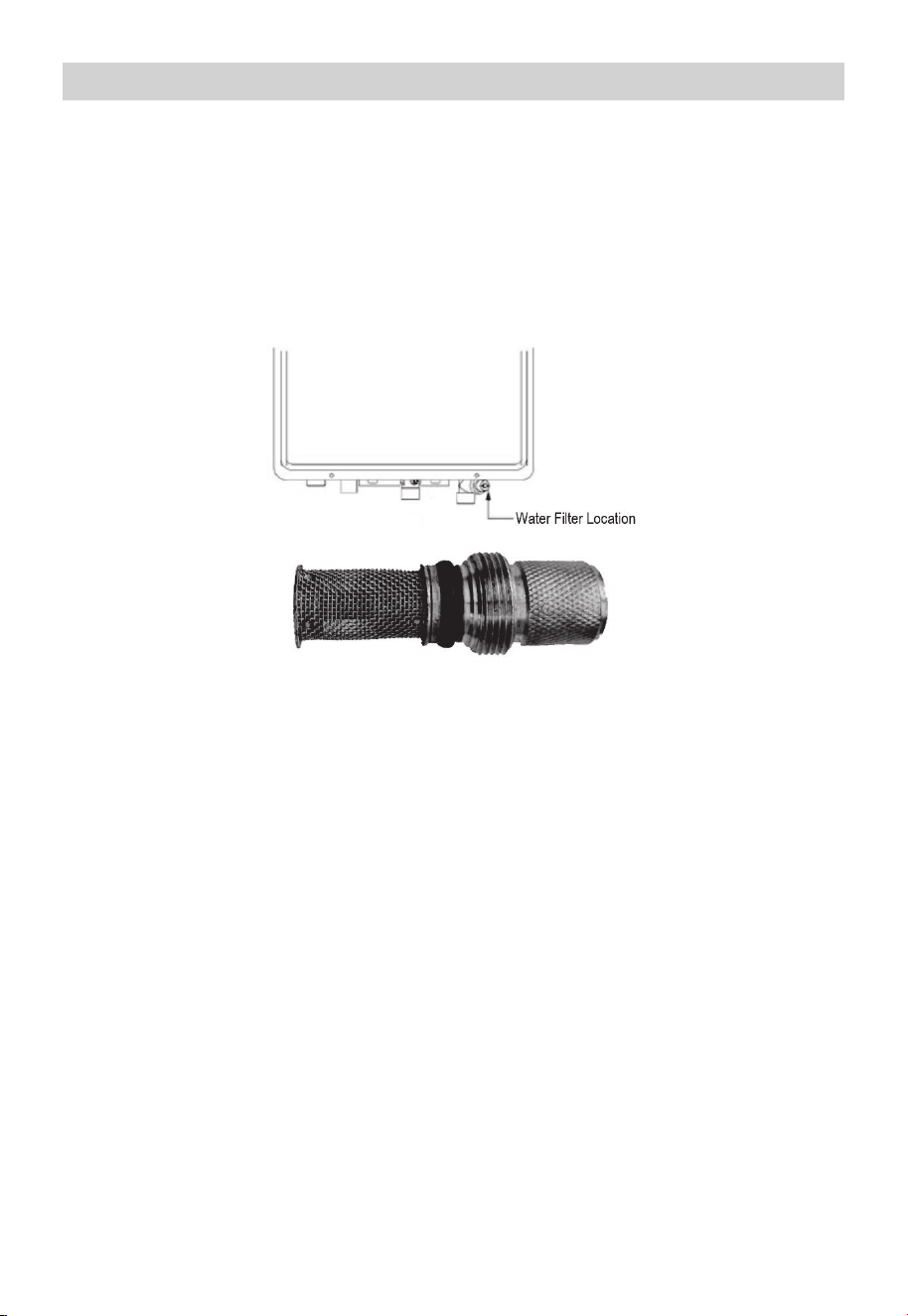
1. Make sure the unit is OFF, the power cord is unplugged, and the electrical power
supply has been disconnected at the circuit breaker.
2. CLOSE the water supply to the heater.
3. Unscrew the water filter and slide the filter out.
4. DO NOT tap the filter as it may deform and/or damage the filter.
5. To remove severe debris, use a soft brush and wash with running water.
6. Return the filter to the water heater and screw in the filter.
7. Plug in the power cord to the outlet and reconnect the electrical power supply and
OPEN the cold water supply to the water heater.
8. The water filter should be cleaned on a monthly basis.
How to Clean the Water Filter
To prevent water scale, lime, or rust deposit buildup and ensure your new tankless water
heater is running as efficiently as possible, it is highly recommended that you clean your
tankless water heater every 6 months. We recommended using a descaling kit, such as
the Kings Peak EZ-Descale Kit, available at our website, www.kingspeakhome.com
Before performing any cleaning and maintenance tasks to this water heater, be sure to
turn the unit OFF and disconnect the power supply.
Vacuum around the water heater for dust, debris, and lint on a regular basis. Clean the
exterior of the water heater by using a damp soft cloth with a few drops of mild
detergent and gently wiping the surfaces of the unit. Wipe any remaining moisture with a
dry soft cloth.
To ensure sufficient ventilation and combustion air supply, proper clearances must be
maintained.
Six (6) Month Cleaning Routine
• Make sure the unit is OFF and the electrical power supply has been disconnected.
• DO NOT scrub the appliance with a brush.
• Use only mild soapy water, other cleaners may damage the surface of the water heater.
• DO NOT remove any label including the rating plate while cleaning or servicing.
Cleaning the Exterior of the Water Heater
Water Filter Unscrewed from Appliance
49

If the water heater is to remain idle for an extended period, the power and water to the
appliance should be turned off.
The water heater and piping should be drained if they might be subjected to freezing
temperatures.
After a long shut-down period, the water heater's operation and controls should be
checked by qualified service personnel.
Vacation and Extended Shut-down
An Anti-Freezing system inside the unit will help to protect from near to slightly below
freezing temperatures, it will in no way guarantee protection from water freezing
damage. DO NOT rely on the anti-freezing system to fully protect the unit from freezing,
especially when exposed to extreme cold environments. Take all precautions to prevent
extreme cold damage the unit.
Anti-freezing Electric Warming System
When the temperature falls below 32° F, water in your plumbing system or water heater
can turn to ice and then expand, causing damage to the water heater. This damage is not
covered under the Limited Product Warranty. If these conditions are anticipated or have
been experienced, please drain the water heater as follows to help, but not guarantee,
protection from freezing water damage:
Draining Procedure
DANGER
Shock Hazard. Make sure the electrical power to the water heater is off to avoid potential
serious injury or damage to components.
DANGER
Combustible materials, such as clothing, cleaning materials, or flammable liquids, etc.,
must not be placed against or next to the water heater.
The anti-freezing device works for the water heater unit, and not the inlet nor outlet
water pipes.
NOTICE
WARNING
Freezing at any point within the plumbing system may result in damage to the water
heater, such as a rupture in your heat exchanger. AII pipes must be adequately protected
from freezing.
This unit is equipped with an automatic heating system that will help to avoid freeze
damage, but the power to the unit and the unit itself must remain ON. Freezing will occur
with no power or power loss. In colder areas, where the air temperature around the unit
is at or under 32° F, freezing will occur if the heating power limit of the anti-freeeze
system is exceeded. If these conditions take place, please follow the procedures
explained below.
50
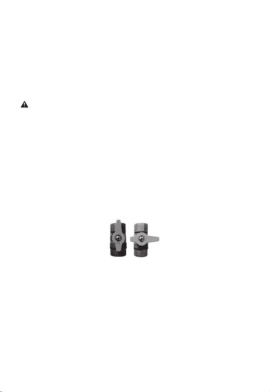
1. CLOSE the main gas valve and unplug power to the unit. Disconnecting the breaker
serving the outlet for this unit at the breaker box is strongly recommended for your
safety. For extra precaution, we recommend waiting at least ten seconds after
disconnecting power to the unit to move to step 2.
2. CLOSE the water Shut-off inlet water valve.
3. OPEN all faucets, cold water should be coming out of all hot water faucets, bypassing
the hot water heater.
4. OPEN the drain valve and allow water to drain for three (3) minutes or until the unit is
empty.
5. Once you are sure all water is out of the unit, CLOSE the drain valve and shut the
faucets.
The water heater may not operate unless the above procedure is followed correctly.
NOTICE
Draining the Water Heater
1. Reattach the water filter, if previously removed for cleaning.
2. OPEN a hot water faucet, then close the hot water outlet drain valve from the unit.
3. OPEN the water shut-off valve and close again after making sure that water comes out
from hot water faucets. (This step is to remove air from the water lines.)
4. Reconnect the power plug of the unit to an outlet.
5. Reconnect the breaker at the breaker box that serves the outlet for this unit.
6. Turn the on/off switch to the ON position, fully OPEN the gas shut-off valve and the
water shut-off valve.
7. Ensure hot water is now available from the open faucet from step 2 above.
Resuming Operation Of The Unit
WARNING
Failure to follow these instructions while draining the water heater can cause serious
damage to the water heater as well as personal injury including scalding.
Manual Gas Appliance
Shut-Off Valve
“OPEN”
Manual Gas Appliance
Shut-Off Valve
“CLOSED / OFF / SHUT”
51
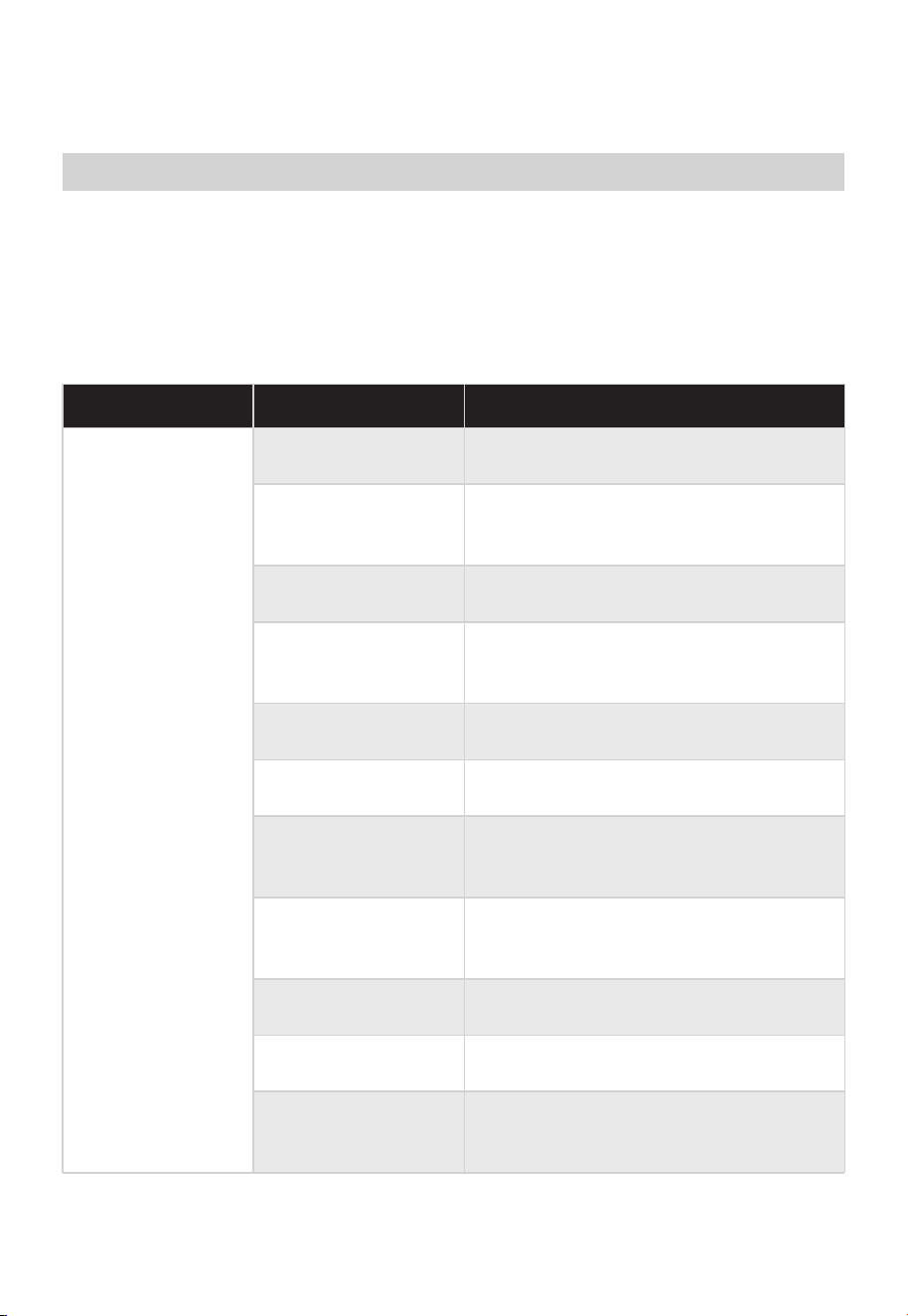
Clean the filter with а toothbrush Water filter is clogged
Check shutoff valve and open fully
Water shutoff valve is
not fully opened
Allow more water to flow
Small amount of
water has been
heated
TROUBLESHOOTING
Save time and money! Review the charts below first and you may not need to call for
service. This water heater incorporates a variety of shut off devices that prevent the
operation of the water heater if undesirable combustion conditions occur, such as the
presence of a blockage of the combustion air vent, or insufficient gas or gas pressure
which can impact the safe operation of the water heater. Please contact a qualified
service technician if this occurs.
Troubleshooting Tips
Before Inquiring to Customer Service
Problem Possible SolutionPossible Cause
Not enough or no
hot water
Water shutoff valve
is not fully opened
Check shutoff valve and open fully
Hot water faucet is
not fully opened
Open hot water faucet completely (The
main burner goes off when incoming
water volume is inadequate)
Water pipes are
frozen
Allow pipes to thaw, DO NOT USE
APPLIANCE until pipes are un-frozen
No electricity or water
supply is cut off
The temperature may
be set too low
Turn the unit “ON”
Increase the temperature setting
Error code displayed
on the control display
panel
See instructions for Error Codes on
Page 34
Mixing Valve
malfunction (if
applicable)
Check and replace if necessary
Unit is not “ON”
Check that proper power is being
supplied and/or water supply is
adequate
52
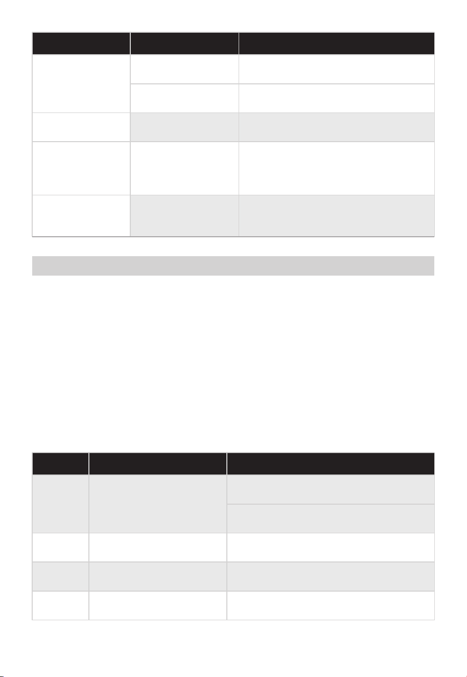
• Close the hot water faucet, turn OFF the unit using the power button on the unit.
• Wait for about five (5) minutes before turning the power ON to the unit.
• Open a hot water faucet.
If the Error Code remains displayed on the unit:
• Close the hot water faucet and turn OFF power to the unit using the button on the
unit.
• Review the Error Code chart below and try the potential solution for the associated
code displayed.
• Resume use of the hot water faucet.
If the Error Code still displays on the unit:
• Close the hot water faucet and turn OFF power to the unit using the button on the
unit.
• Call customer service at (855)855-4647 for further assistance.
When an Error Code is Displayed
Error Code Guide and Possible Solutions
Problem Possible SolutionPossible Cause
Water not hot
enough
Water Water too
hothot enough
An error code is
showing on the
display
Fan continues to
rotate after hot
water faucet is
closed
The temperature
may be set too low
Increase the temperature setting
Error Code Potential Solution Error Description
Water outlet temperature
sensor failure
Connect the water outlet temperature
sensor
Replace the water outlet temperature
sensor
Accidental flameout failure
Turn off the hot water faucet or turn OFF
the power button on the display
The gas valve is not
fully opened
Check and open the gas valve fully
The temperature is
set too high
Decrease the temperature setting
This function is to
purge unburned gas
for 10-15 seconds
The unit has detected
an abnormal
operation
Please see the next page for Error Code
Explanations and Potential Solutions
Normal operation.
There is no need to call for service
E0
E1
Fake flame failure
Turn off the hot water faucet or turn OFF
the power button on the display
E2
Thermostat failure
Connect the thermostat E3
53
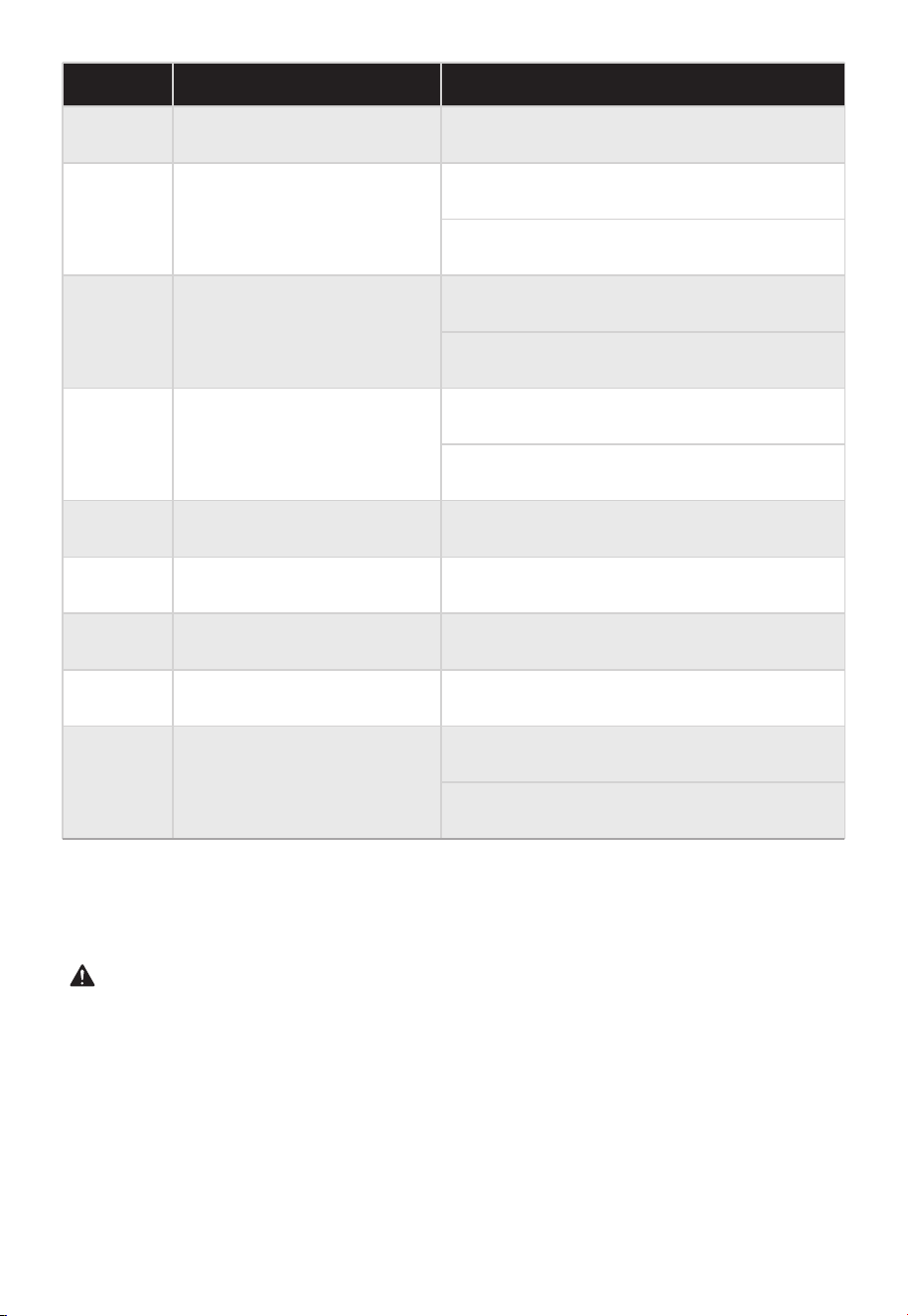
Error Code Potential Solution Error Description
Thermostat failure
Water outlet sensor
recorded an
“overtemperature” alert
failure
Replace the thermostat
Connect the water outlet temperature
sensor
Replace the water outlet temperature
sensor
E3
E4
Fan failure
Connect the fan
E5
Replace the fan
Solenoid valve failure
Connect the valve
E6
Timeout fault
EE
Replace the valve
Turn off the hot water faucet or turn OFF
the power button on the display
Ignition failure
C0
Turn off the hot water faucet or turn OFF
the power button on the display
Residual flame failure
C1
Turn off the hot water faucet or turn OFF
the power button on the display
Vent blockage
C4 Clean the vent pipe
Cold water inlet temperature
sensor failure
F2
Connect the water inlet temperature sensor
Replace the water inlet temperature sensor
If an Error Code other than those listed in the chart below is displayed, immediately close
the hot water faucet, take note of the Error Code, turn OFF power to the unit, and call
the customer assistance number at (855)855-4647.
NOTICE
WARNING
For your safety, DO NOT attempt to repair gas piping, the display, burners, vent
connectors, or other safety devices. Refer all repairs to qualified service personnel. This
product is not serviceable by the end consumer outside of the remedies outlined in the
“TROUBLESHOOTING TIPS” and “ERROR CODES” sections of this manual. Failure to
defer service to a professional may result in property damage, injury, and/or loss of life.
54

DANGER
Make sure the unit is OFF, the power cord fully disconnected from the outlet, and the
power to the outlet that services this unit is disconnected at the breaker before removing
the protective front panel cover FOR ANY REASON.
55

Certifications and Safety Approvals
Declaration of Conformity
We hereby confirm that the following customer model names and Midea model names
match each other respectively
CERTIFICATIONS
AND SAFETY APPROVALS
Declaration of Conformity
Brand Midea model Marketing Model
Midea
NSF Compliance: Fabricate and label equipment components that will be in contact with
potable water to comply with NSF 61 and NSF 372
CSA Comploiance:Gas Water Heaters, Volume III, Gas Fired Automatic Storage Type
Water Heaters with Input Ratings above 75,000 BTUH, Circulating and Instantaneous.
JSQ40-20VHS-NG
JSQ40-20VHS-LP
JSQ52-26VHS-NG
JSQ52-26VHS-LP
MGWH150ISNN
MGWH150ISPN
MGWH199ISNN
MGWH199ISPN
56

logo, word marks, trade name, trade dress and all versions there of are
trademarks, copyrights and other intellectual property rights, and all goodwill derived
valuable assets of Midea Group and/or its affiliates (“Midea”), to which Midea owns
from using any part of an Midea trademark. Use of Midea trademark for commercial
purposes without the prior written consent of Midea may constitute trademark
infringement or unfair competition in violation of relevant laws.
This manual is created by Midea and Midea reserves all copyrights thereof. No entity or
individual may use, duplicate, modify, distribute in whole or in part this manual, or
bundle or sell with other products without the prior written consent of Midea.
All the described functions and instructions were up to date at the time of printing this
manual. However, the actual product may vary due to improved functions and designs.
TRADEMARKS, COPYRIGHTS
AND LEGAL STATEMENT
57
device must be returned to official collection point for
DISPOSAL AND RECYCLING
Important Instructions for Environment
Compliance with the WEEE Directive and Disposing of the Waster Product:
This product complies with EU WEEE Directive (2012/19/EU). This product bears a
classification symbol for waster electrical and electronic equipment (WEEE).
This symbol indicates that this product shall not be disposed
with other household wastes at the end of its service life. Used
recycling of electrical electronic devices. To find these
collection systems please contact to your local authorities or
retailer where the product was purchased. Each household
performs important role in recovering and recycling of old
appliance. Appropriate disposal of used appliance helps
prevent potential negative consequences for the environment
and human health.
Compliance with RoHS Directive
The product you have purchased complies with EU RoHS Directive (2011/65/EU). It does
not contain harmful and prohibited materials specified in the Directive.
Package Information
Packaging materials of the product are manufactured from
recyclable materials in accordance with our National Environ-
ment Regulations. Do not dispose of the packaging materials
together with the domestic or other wastes. Take them to the
packaging material collection points designated by the local
authorities.
58

DATA PROTECTION NOTICE
For the provision of the services agreed with the customer,
we agree to comply without restriction with all stipulations of applicable data protection
law, in line with agreed countries within which services to the customer will be delivered,
as well as, where applicable, the EU General Data Protection Regulation (GDPR).
Generally, our data processing is to fulfil our obligation under contract with you and for
product safety reasons, to safeguard your rights in connection with warranty and
product registration questions. In some cases, but only if appropriate data protection is
ensured, personal data might be transferred to recipients located outside of the
European Economic Area.
Further information are provided on request. You can contact our Data Protection
Officer via [email protected]. To exercise your rights such as right to object your
personal date being processed for direct marketing purposes, please contact us via
[email protected]. To find further information, please follow the QR Code.
59


www.midea.com
xxxxxxxxxxxxxxx
V1.0