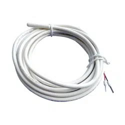
The SALUS AFTS30M Floor Sensor is designed to measure slab or oor temperature for radiant heating systems when used in
conjunction with a SALUS AS20WRF/BRF Wireless Thermostat, an AWRT10RF Wireless Radiant Thermostat or an AHTR5024 Wired
Digital Thermostat. This product is suitable for embedding in concrete ooring or snow melting slabs. The SALUS AFTS30M is
supplied with 3 meters [10 feet] of 2-conductor wire.
Features Specications
• 10 kΩ Thermistor
• ABS sensor housing
for corrosion
resistance
• 3 meter [10 ft]
connector wire
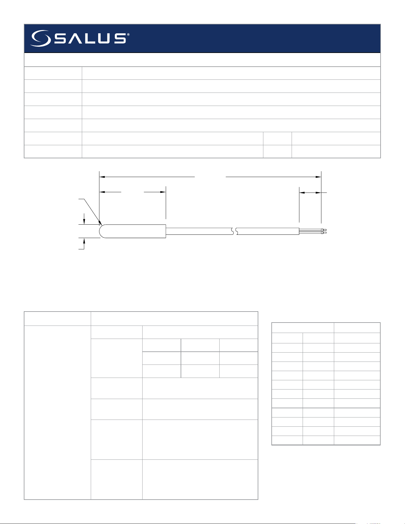
Model AFTS30M Floor Sensor
Package
Dimensions
Length Width Height
6.18” 2.68” 1.38”
15.7 cm
6.8 cm 3.5 cm
Materials of
Construction
ABS Housing; PVC Insulated
Copper Wire
Operating
Temperature
-50°C to 60°C (-58°F to 140°F)
Sensor
Specications
10 kΩ resistance at 25°C ±0.2 K (77°F)
Compatible
Devices
AS20WRF/BRF Wireless Thermostat,
AWRT10RF Wireless Radiant Thermostat
and AHTR5024 Wired Digital Thermostat
SUBMITTAL
AFTS30M – Floor Sensor
Job or Customer
Location
Engineer
Contractor
SALUS Rep
Submitted by Date
Approved by Date
THIS DOCUMENT CONTAINS
INFORMATION PROPRIETARY
TO AZ ENGINEERING.
DISCLOSURE OF ANY
INFORMATION CONVEYED OR
IMPLIED BY THIS DOCUMENT
WITHOUT EXPRESS WRITTEN
CONSENT BY AZ
ENGINEERING IS FORBIDDEN.
APPROVED BY
DATE
AZ ENGINEERING LLC
FLOOR SENSOR - AFTS30M
SCALE: DRAWING NO: REVISION:
SHEET 1 OF 1
DATE:DRAWN BY:
CN:
FOR RADIANT FLOOR HEAT
SCI-180713-01
01
NOT TO SCALE
--
SCEARCE 2018-07-13
REVISION
BY:
0
DAS
DATE:
2018-09-10
Changed dimensions from mm with alternate units of inches to inches with
alternate units of mm. Changed overall length to feet with alternate units of
meters. Updated Model number from NTSG210FZ235 to AFTS30M. Updated
description from slab sensor to floor sensor.
NOTES:
1) Unless otherwise noted dimensions inches [mm]
2) Tolerances are +/- 0.5 mm [0.02 in.]
KEY:
WATER
ELECTRICAL
CONTROL BOUNDARY
1.18"
[30mm]
0.24"
[6mm]
R0.12"
[R3mm]
0.39"
[10mm]
100' [30 m]
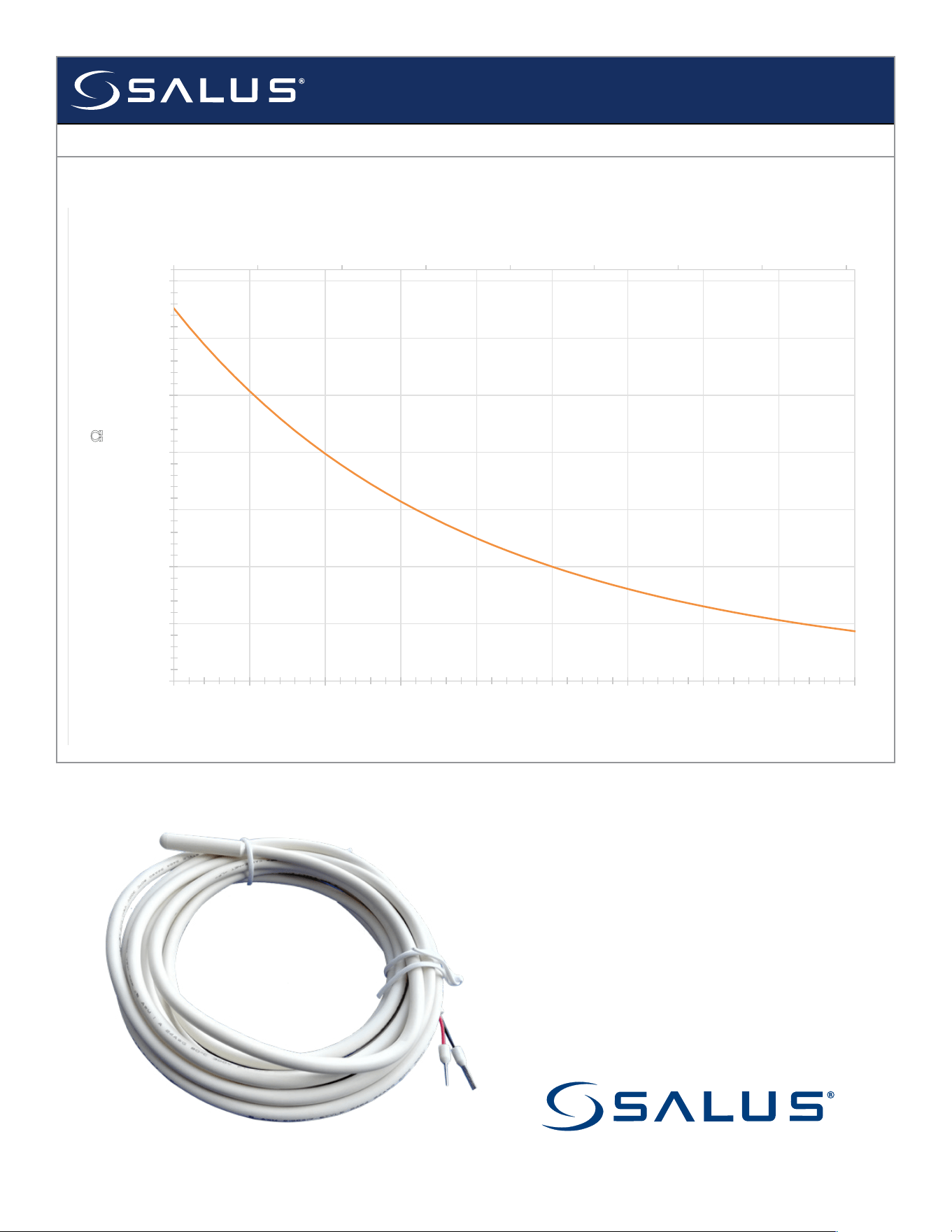
Temperature Resistance
°C °F Ω
0 32 32,596
5 41 25,367
10 50 19,889
15 59 15,708
20 68 12,492
25 77 10,000
30 86 8,055
35 95 6,527
40 104 5,319
45 113 4,357
50 122 3,588
Thermistor Resistance Chart
A graphical representation of these
relationships is included on the back
of this sheet.
SUBMITTAL
AFTS30M – Floor Sensor
RTD Thermistor Chart
32 42 52 62 72 82 92 102 112
-
5,000
10,000
15,000
20,000
25,000
30,000
35,000
0 5 10 15 20 25 30 35 40 45
Temperature(⁰F)
Resistance(Ω)
Temperature(⁰C)
850 Main Street
Redwood City, CA 94603