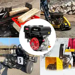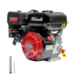
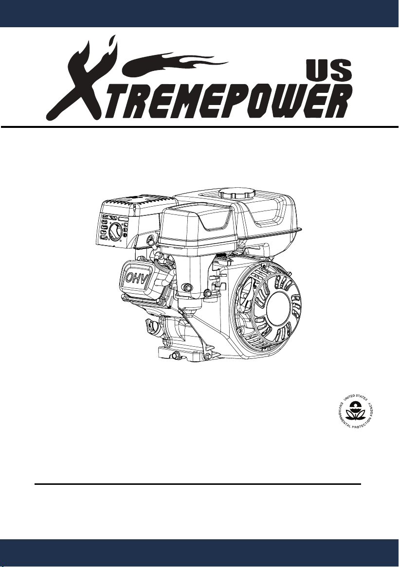
Gasoline Engine
Owner's Manual
SKU: 62037
IMPORTANT:
Keep this manual for safety warnings and precautions, assembly, operating,
inspection and maintenance procedures.
Read all precautions and instructions carefully before operating this engine.
This manual should be considered a permanent part of this engine and should
remain with the engine if resold.
Chongqing Rato reserves the right to discontinue, change and improve its products
at any time without notice or obligation to the purchaser.

1
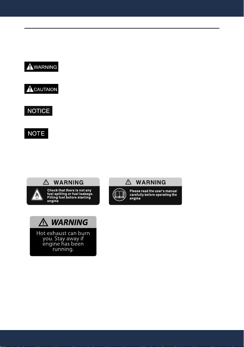
SAFETY PRECAUTIONS
A hazard that could result in death or serious injury.
A hazard that could result in minor or moderate
personal injury.
A hazard that could result in property damage.
Important installation, operation, or maintenance
information.
17
18
19
24
26
31
33
2
SAFETY PRECAUTIONS

CONTENTS
SAFETY PRECAUTIONS …………………………………………… 2
I. OPERATING PRECAUTIONS …………………………………… 4
II. PARTS DESCRIPTION …………………………………………… 6
III. PRE-OPERATE INSPECTION …………………………………… 7
IV. STARTING THE ENGINE …………………………………… 10
V. RUNNING THE ENGINE ……………………………………… 12
VI. STOPPING THE ENGINE …………………………………… 15
VII.EXHAUST CONTROL SYSTEM …………………………… 16
VIII. MAINTENANCE …………………………………………… 17
IX. TRANSPORT AND STORAGE ……………………………… 22
X. TROUBLESHOOTING ………………………………………… 24
XI. SPECIFICATIONS …………………………………………… 26
XII. ELECTRIC DIAGRAM ……………………………………… 27
XIII. WEARING PARTS AND ACCESSORIES LIST …………… 28
3
TABLE OF CONTENTS
I. OPERATING PRECAUTIONS
Read all instructions carefully before operating this
engine. Failure to follow all instructions may result in
The warnings and precautions listed in this manual cannot cover all
possible conditions and situations that may occur. It must be understood
by the operator that common sense and caution are factors which cannot
be built into this product, but must be supplied by the operator.
1. CARBON MONOXIDE HAZARD
Using an engine indoors can kill you in minutes.
Engine exhaust contains carbon monoxide. This is a poison you
cannot see or smell. NEVER use inside a home or garage, even if
doors and windows are open. Only use outside and far away from
windows, doors and vents.
2. Strictly set the engine according to the regulated power on the owner's
manual. Do not overload, overspeed the engine or run it with low load
and at low speed in a long time.
3. Fire Hazard! Do not fill fuel tank while engine is running. Do not
operate the engine if gasoline has been spilled. Clean the spilled
4. Hot parts can cause severe burns. Do not touch engine during use. Let
engine cool down after use.
5. Keep children away from this engine, especially while it is running.
4
OPERATING PRECAUTIONS

6. Use proper transport devices to avoid rolling, slipping and tilting when
transporting the engine.
7. Use recommended oil type and fuel type.
8. Wear ear protection when operating or working around the engine
while it is running.
9. Do not cover the engine while it is running.
10. Follow the maintenance schedule to keep the engine in good working
condition.
·
5
·
5
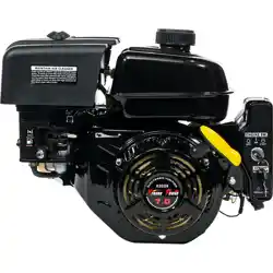
OPERATING PRECAUTIONS
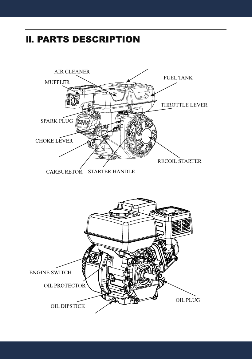
FUEL TANK CAP
OIL DRAIN BOLT
FUEL VALVE
6
PARTS DESCRITPION
III. PRE-OPERATE INSPECTION
1. ENGINE OIL
Your Warranty is void if the engines is not properly
or no oil can cause severe engine damage.
The oil alert system(if equipped) will automatically stop the engine
before the oil level falls below safe limit. However, to avoid an
unexpected shutdown, be sure to check the engine oil before starting the
engine.
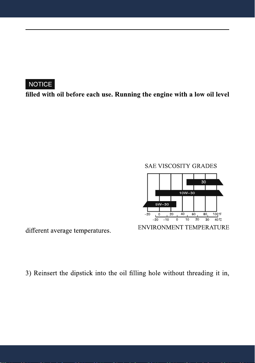
Use 4-stroke engine oil. API (American
Petroleum Institute) service class SJ or
higher are acceptable.
SAE 10W-30 oil is recommended for
general use.
The SAE Viscosity Grades chart
below shows other viscosities to use in
CHECKING AND FILLING OIL
1) Make sure the engine is stopped and in a level position.
2) Remove the dipstick and clean it.
and remove it to check oil level.
4) If the oil level is too low, add the recommended engine oil up to the
upper limit level.
5) Reinstall the dipstick.
6) Lubrication oil capacity: 62037 0.5L
7
PRE-OPERATE INSPECTION
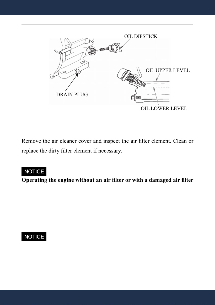
2. AIR CLEANER
will damage the engine. This type of damage is not covered by the
Warranty.
3. CHECKING AND ADDING FUEL
Use clean, fresh, regular unleaded gasoline with a minimum octane
rating of 87 and an ethanol content of 10% or less by volume. (E10)
Any damages or hazards caused by using improper gasoline are not
covered by the Warranty.
8
PRE-OPERATE INSPECTION
1) Remove the fuel tank cap and check fuel level.
2) Slowly add gasoline to the tank. Recommended fuel level is 1 inch.
2) Fill the tank in a well-ventilated area with the engine stopped and
away from heat and ignition sources.
temperature rise.
7) Gasoline is a skin irritant and needs to be cleaned up immediately
if spilled on skin or cloths.
8) Keep out of reach of children.
Fuel tank capacity
:
62037 2.6L
9
PRE-OPERATE INSPECTION
IV.STARTING THE ENGINE
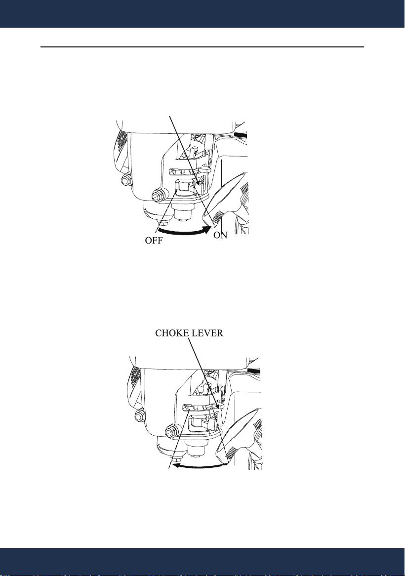
1.Move the fuel valve to the "ON" position.
2. To start a cold engine, move the choke lever to the CHOCK position.
To restart a warm engine, leave the choke lever in the RUN position.
CHOKE
FUEL VALVE
RUN
10
STARTING THE ENGINE
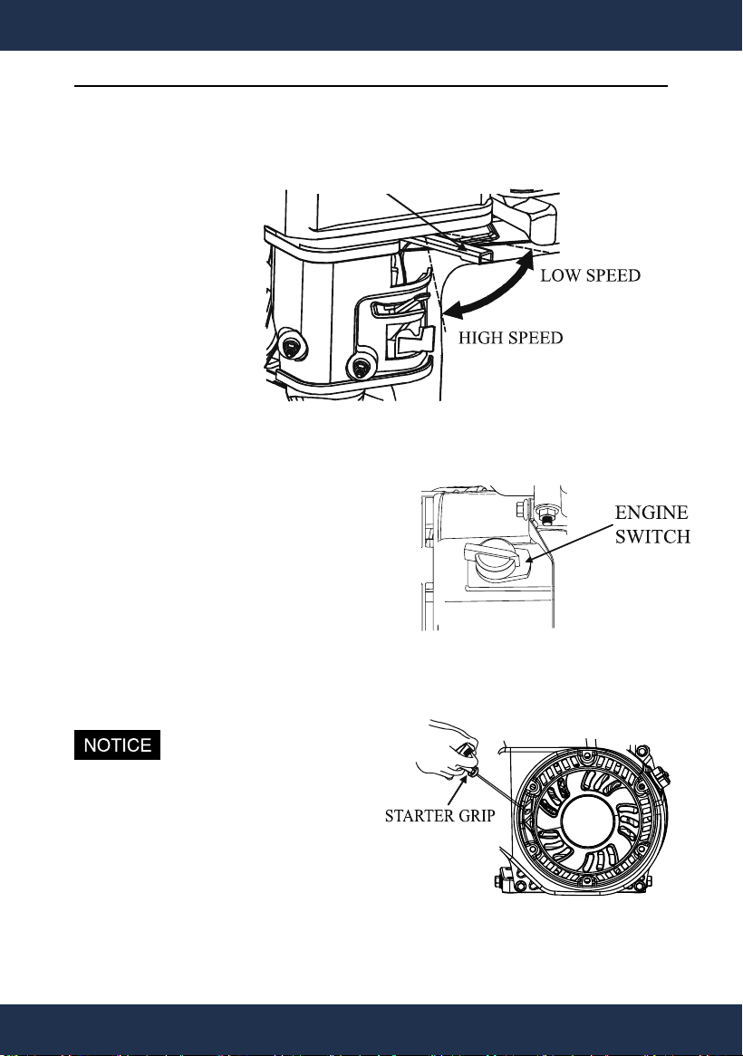
3.Slide the throttle lever to 1/3 away from low speed position(the
"Turtle").
4. Start the engine
Recoil starter:
Turn the engine switch to the"ON"
(OPEN) position.
Pull the starter grip gently until
resistance is felt. Allow cable to retract
fully and then pull it quickly. Repeat
until the engine starts.
Don't allow the starter grip to
snap back against the engine.
Hold it as it recoils so it
doesn't hit the engine.
THROTTLE LEVER
11
STARTING THE ENGINE
V.RUNNING THE ENGINE
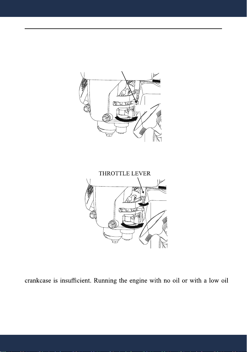
1. Allow the engine to run for several seconds. Move the chock lever
slowly to the "RUN" position.
2. Adjust the throttle lever as needed.
ENGINE OILALARM
The engine oil alarm system is designed to function when engine oil in the
level can cause severe damage to the engine. The engine oil alert system
will automatically stop the engine when the oil falls below the threshold
level.
CHOKE LEVER
RUN
12
RUNNING THE ENGINE
any other inspection.
HIGH ALTITUDE KIT REPLACEMENT
FOR EPAIII ENGINES
3000-6000ft. / 6000-8000ft. of elevation
At high altitude, the standard carburetor air-fuel mixture will be too
rich. Performance will decrease and fuel consumption will increase. A
very rich mixture will also foul the spark plug and cause hard starting.
at higher altitudes. Proper operation can be ensured by installing an
altitude kit when required. See the table below to determine when an
altitude kit is required. Operating this engine/equipment without the
proper altitude kit installed may increase the engine’s emissions and
decrease fuel economy and performance. Kits may be obtained from any
13
RUNNING THE ENGINE
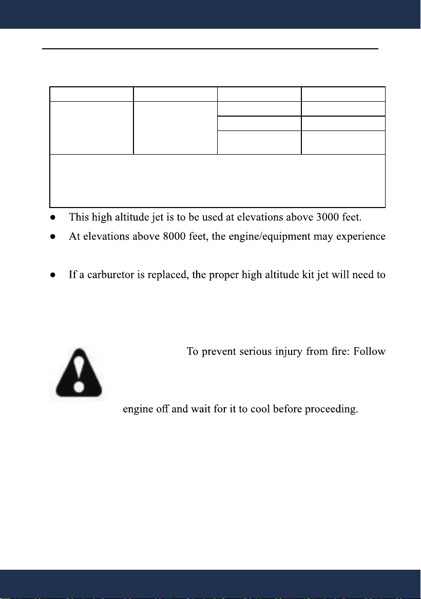
Equipment * Fuel Altitude Range** Kit Part Number
Equipment with
engines abo v e
80cc
Gasoline 0 – 3000 ft Not Required
3000 – 6000 ft Altitude kit 1#
6000 – 8000 ft Altitude kit 2#
* Engine, Generator Set, Pressure Washer, Walk-Behind Lawnmower,
Compressor, Pump, Tiller etc.
** Elevation above sea level.
decreased performance, even with the high altitude kit.
be installed into the replacement carburetor.
WARNING!
the kit procedures in a well-ventilated area away from
ignition sources. If the engine is hot from use, shut the
NOTICE: The warranty may be void if necessary
adjustments are not made for high altitude use.
14
RUNNING THE ENGINE
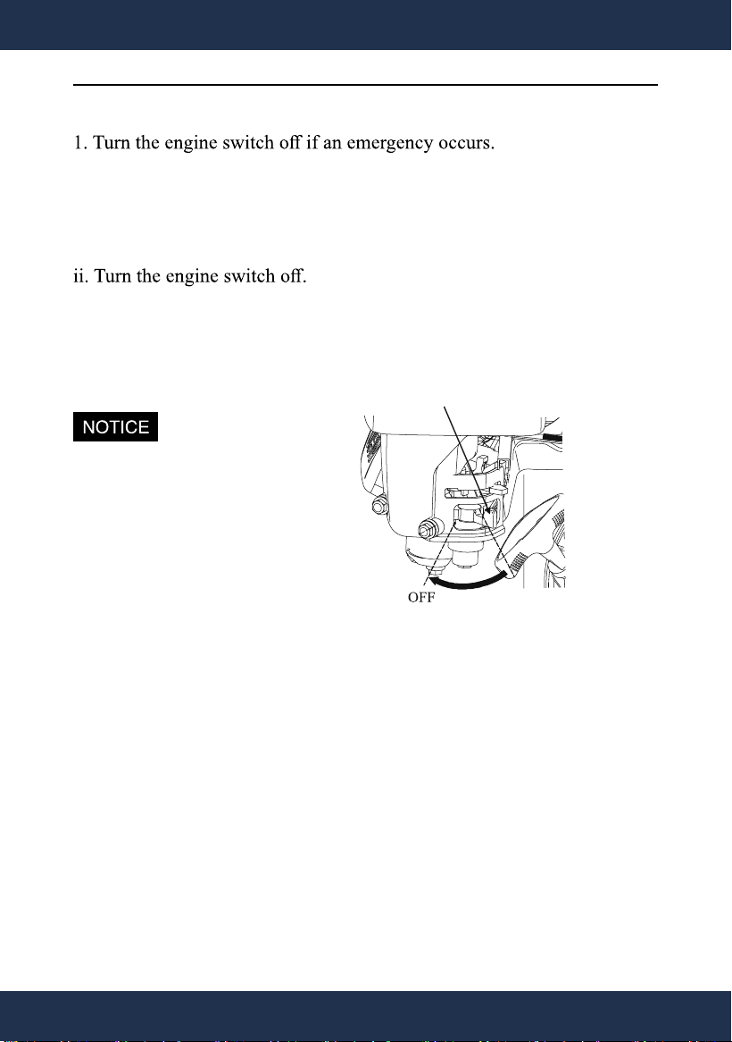
VI.STOPPING THE ENGINE
2. Under normal conditions, please use the following procedure:
i. Move the throttle lever to the low speed position(the "Turtle").
iii. Move the fuel valve to OFF position.
Sudden stop at high-speed
and heavy-load condition will
cause engine damage.
FUEL VALVE
15
STOPING THE ENGINE
VII.EXHAUST CONTROL SYSTEM
Running engine can produce carbon monoxide, hydrocarbon and oxides
of nitrogen. carbon monoxide is toxic. Hydrocarbon and oxides of
nitrogen can react chemically to produce smoke.
To keep the exhaust of your engine within the EPA emission standard,
pay special attention the following:
1. Maintenance
The owner/operator should strictly follow the Maintenance schedule and
complete all scheduled maintenance in a timely manner. If the engine
always works under severe conditions, maintenance should be performed
more frequently.
b. Unstable idling speed
c. Abnormal black smoke or fuel consumption
e. Premature ignition
If you are experiencing any of above problems, contact an authorized
service dealer for help.
16
EXHAUST CONTROL SYSTEM
VIII. MAINTENANCE
1.The engine must be properly maintained to ensure its operation be safe,
economy and trouble-free, as well as eco-friendly.
In order to keep your gasoline engine in good working condition, it must
be periodically serviced. The following maintenance schedule and routine
inspection procedures must be carefully followed:
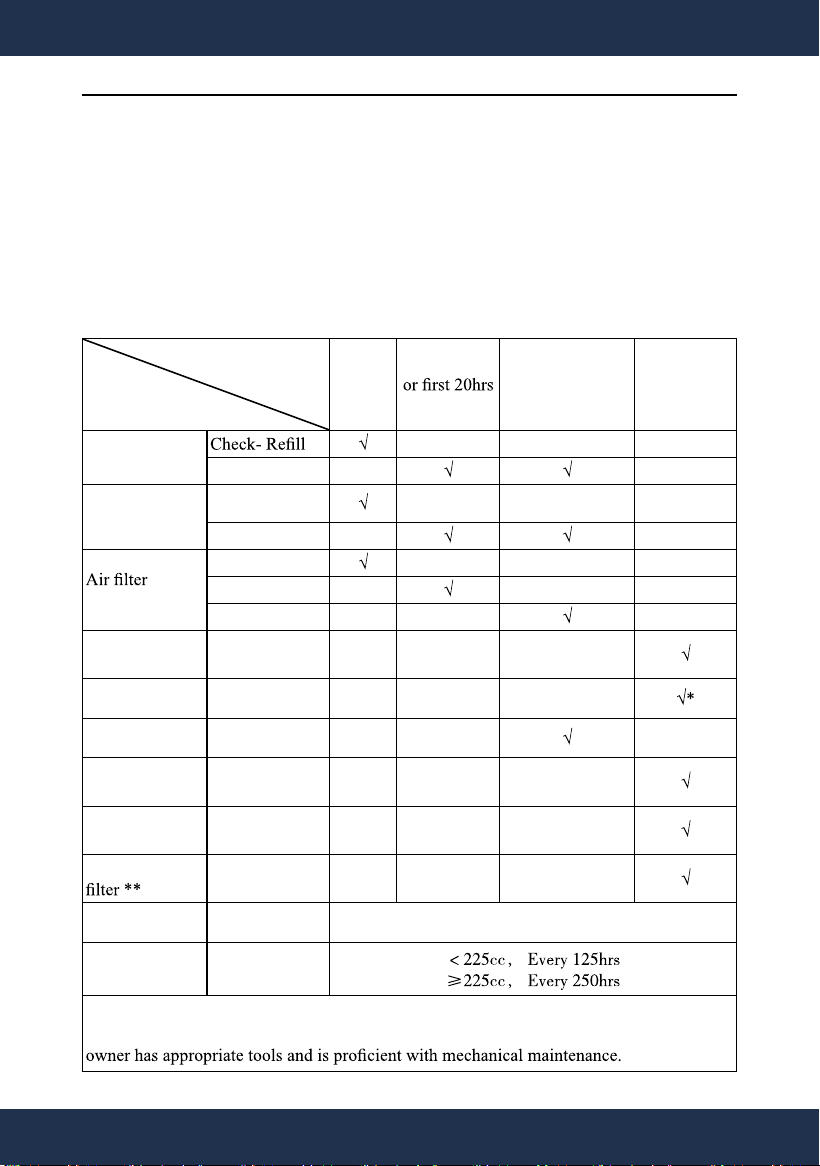
Frequency
Items
Each
time
First 1 month
of operation
Thereafter, every
3 months or every
50hrs of operation
Every year or
every 100 hrs
of operation
Engine oil
Replace
Reduction gear
oil(if equipped)
Oil level check
Replace
element
Check
Clean
Replace
Deposit Cup( if
equipped)
Clean
Spark Plug Check - adjust
Spark arrester Clean
Idling ( if
equipped)**
Check - adjust
Valve clearance
**
Check-adjust
Fuel tank & fuel
Clean
Fuel line Check Every 2 years( change if necessary)
Cylinder head,
piston
Clean up carbon
**
* These items should be replaced if replacement needed.
** These items should be maintained and repaired by our authorized dealer, unless the
17
MAINTENANCE
load, change the oil every 25 hours.
Stop the engine before servicing. Put the engine on a level surface
and remove the spark plug cap to prevent the engine from starting.
Do not operate the engine in a poorly ventilated room or other
enclosed area. Be sure to keep good ventilation in working area. The
cause shock, unconsciousness and even death.
18
MAINTENANCE
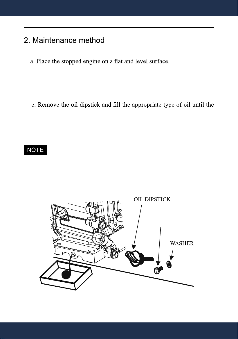
1) Engine oil change
b. Place a drain pan underneath the crankcase's drain plug.
c. Remove the oil drain bolt and tilt the engine slightly to drain the oil.
d. Reinstall the oil drain bolt and tighten it.
oil level is at the upper limit level.
f. Thread the dipstick back and clean the area around it.
For the sake of environmental protection, we suggest you collect the
drained oil in a sealed container and take it to a designated recycle
bin.
OIL DRAIN BOLT
19
MAINTENANCE
2) Maintenance of air cleaner
Air filter/air cleaner is to protect the engine by filtering dust and
debris from the intake air. A dirty air filter will restrict air flow to the
carburetor, reducing engine performance. If you operate the engine in
very dusty areas, clean the air filter more often than specified in the
MAINTENANCE schedule.
can cause engine damage and will void the Warranty.
a. Remove the air cleaner cover.
b. Remove the foam or paper element.
In a well-ventilated area away from bystanders, use pressurized air to
it.
For foam element:
Wash the element in warm water and mild detergent several times.
d. Place the new filter or cleaned filter in the assembly and secure the
cover before use.
20
MAINTENANCE
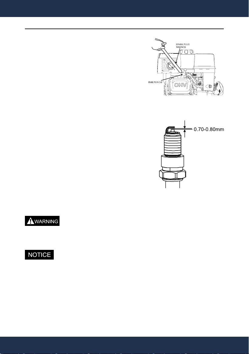
3) Spark plug maintenance
Spark plug type: F 6 RTC, F6TC or
equivalent types.
a. Remove the spark plug cap from the
spark plug.
b. Use a spark plug socket tool to remove
the plug.
c. Inspect the electrode on the plug. Clean
out debris around the spark plug or replace
it with a new one if necessary.
si pag gulp kraps eht erus ekaM .d
0.7~0.8mm.
e. Firmly reinstall the plug.
f. Attach the spark plug cap to the spark
plug.
Be careful of unintentional contact with the hot surface around the
spark plug area. Allow the engine to cool before any maintenance.
Using an incorrect spark plug may damage the engine.
Tighten the spark plug properly. If loose, the spark plug will cause
overheat. If overtightened, the threads in the engine block will be
damaged.
21
MAINTENANCE
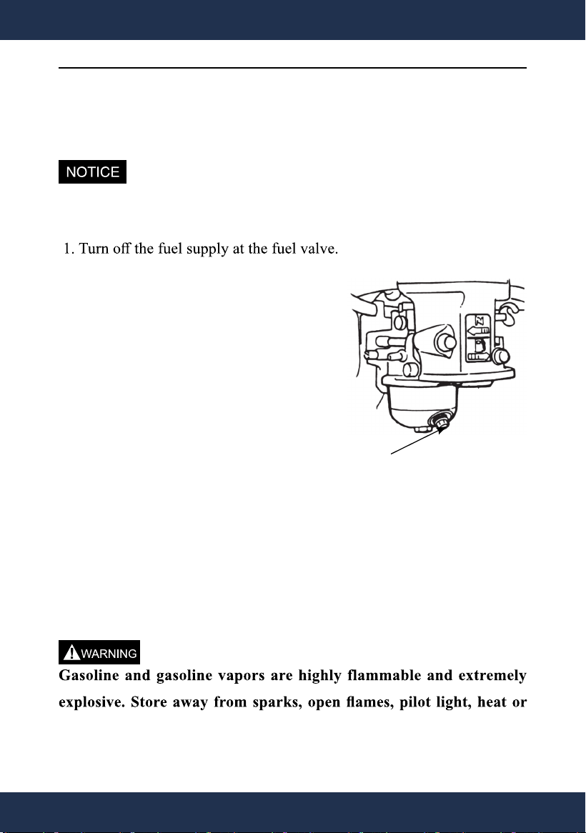
IX. TRANSPORT AND STORAGE
Before transporting the engine, allow the engine to properly cool and
make sure that the fuel valve is in the OFF position.
Allow the engine to cool completely before storage.
For short-term storage (up to 1 month)
2. Use a funnel under the carburetor
drain bolt to avoid spillage.
3. Remove the carburetor drain bolt to
drain the fuel.
For long-term storage (more than 1
month)
1. Turn the fuel valve to ON position.
2. Place a fuel container under the
carburetor. Use a funnel under the
carburetor drain bolt to avoid spillage. Remove the drain bolt to
empty the fuel tank.
3. Replace and tighten the carburetor drain bolt. Be sure to properly
dispose of the drained fuel according to local guidelines.
other sources of ignition.
CARBURETOR DRAIN BOLT
22
TRANSPORT AND STORAGE
If the gasoline tank and carburetor have been properly emptied of all
gasoline prior to the engine being stored, follow the blow steps when
removing from storage.
1. Add fuel according to CHECKING AND ADDING FUEL.
2. Turn the fuel valve to ON position.
3. After 5 minutes check the carburetor and air filter areas for any
leakage gasoline. If leakage occurs, clean or replace the carburetor. If
no leakage, turn the fuel valve to OFF position.
4. Add engine oil according to CHECKING AND FILLING OIL.
necessary.
6. Start the engine according to the instruction.
23
TRANSPORT AND STORAGE
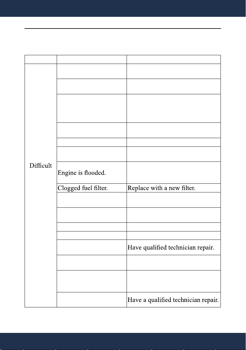
X.TROUBLESHOOTING
PROBLEM
CAUSE SOLUTION
Engine
Starting
or
Engine
Not
Start.
No fuel or fuel valve
closed.
Add fuel or turn on the fuel valve.
For cold engine, choke
not in CHOKE position.
Move chock lever to CHOCK
position.
Wrong fuel type.
Use clean, fresh, regular unleaded
gasoline with a minimum octane
rating of 87 and an ethanol content5
of 10% or less by volume. (E10)
Water in fuel or old
(deteriorated) fuel.
Drain fuel and replace with fresh
fuel.
Carburetor not primed. Pull on starter grip to prime.
Dirty fuel passageways.
Clean out passageways using fuel
additive.
Wait 5 minutes. Move choke to
RUN position, pull the starter grip
and repeat until engine starts.
Spark plug cap not
connected securely.
Tighten the spark plug cap.
Spark plug electrode wet
or dirty.
Clean spark plug.
Incorrect spark plug gap. Adjust spark plug gap or replace..
Damaged spark plug cap. Replace a new cap.
Incorrect spark timing or
faulty ignition system.
Loosen or broken spark
plug. (Hissing occurs)
Tighten spark plug or replace with
a new spark plug.
Loosen or broken cylinder
head or damaged head
gasket. ( Hissing occurs)
Tighten head or replace with a
new head gasket.
Engine valves
misadjusted or stuck.
24
TROUBLESHOOTING
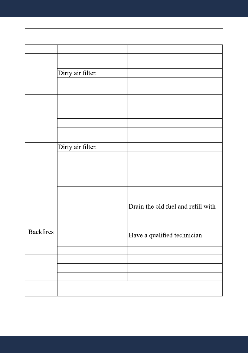
PROBLEM
CAUSE SOLUTION
Engine
Runs
Roughly
Choke in the wrong
position.
Move choke lever to the RUN
position.
Clean or replace with a new one.
Dirty fuel valve. Clean the fuel valve.
Clogged spark arrester. Clean spark arrester.
Engine
Stops
Suddenly
Low oil level. Fill engine oil to proper level.
Empty fuel tank or wrong
fuel type.
See CHECK AND ADDING
FUEL.
Wrong fuel tank cap. Replace fuel cap.
Disconnected spark plug
cap.
Secure spark plug cap.
Engine
stops
under
Heavy
load
Clean or replace with a new one.
Engine running cold.
Allow engine warms up before
operation..
Engine
Knocks
Engine overloaded. Do not exceed rating load.
Wrong fuel type.
See CHECK AND ADDING
FUEL.
Engine
Impure gasoline or
wrong fuel type.
fresh gasoline.
See CHECK AND ADDING
FUEL.
Intake valve stuck or
overheated engine.
diagnose the engine.
Incorrect timing. Check engine timing.
Engine
Overheated
Low engine oil level. Add engine oil to proper level.
Clogged exhaust pipe. Clean exhaust pipe.
Cooling fan blocked. Clean cooling fan.
Other
Contact an authorized service dealer for technical
support.
25
TROUBLESHOOTING
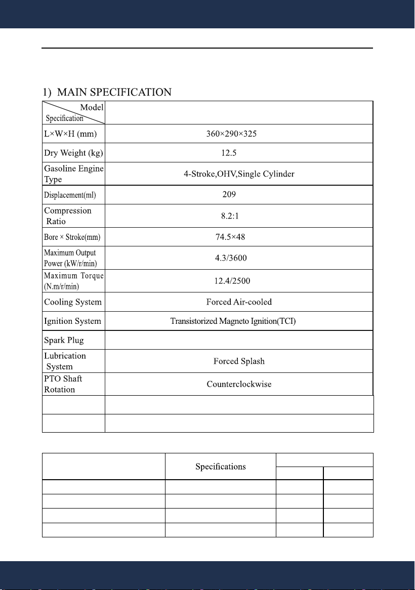
XI.SPECIFICATIONS
62037
F6TC or F6RTC
Spark Plug Gap 0.7- 0.8mm
Valve clearance Intake: 0.05-0.10mm Exhaust: 0.05-0.10mm
2) TORQUE OF IMPORTANT BOLTS
Torque Valve
N
·
m
Kg
·
m
Connection-Rod Bolt M7×32(special) 13±1 1.0
Cylinder Head Bolt M8×60 28±2 1.0
Flywheel Nut M14×1.5(special) 75±7 7.5
Lock Nut Of Rocker Arm Shaft M6 10±2 1.0
26
SPECIFICATIONS
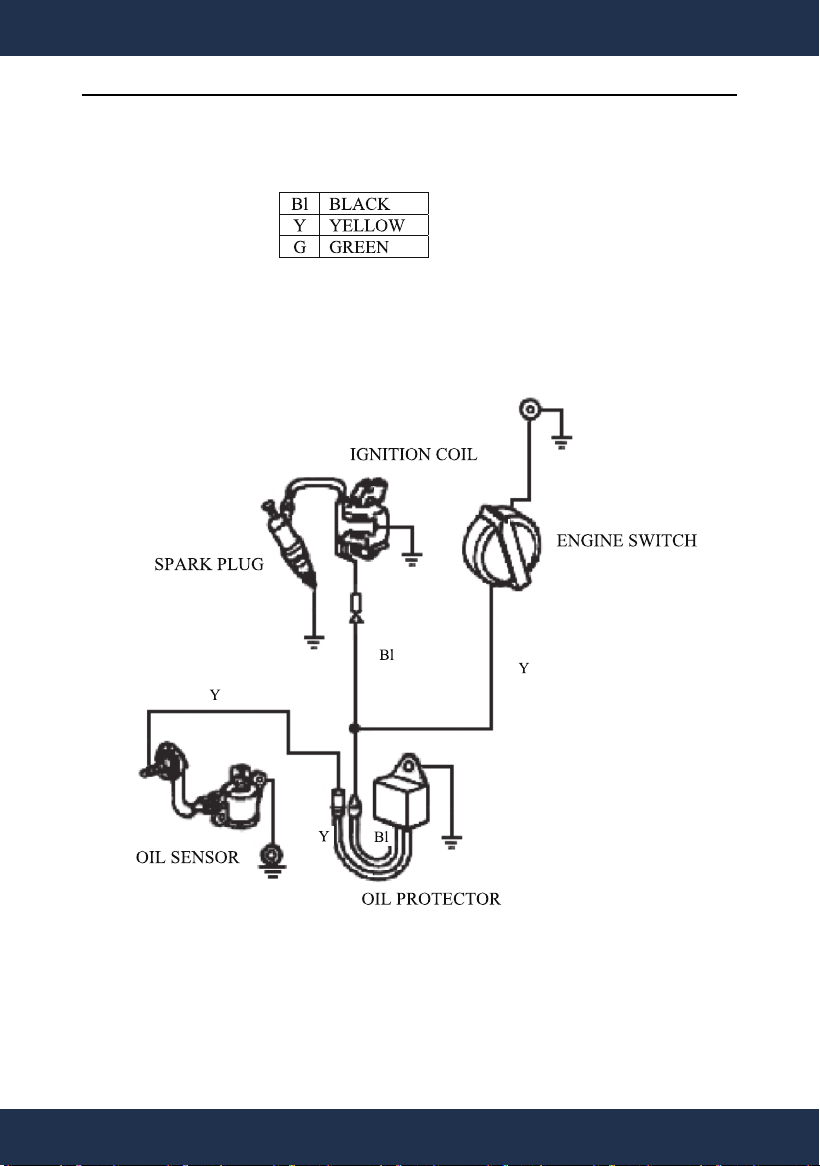
XII.ELECTRIC DIAGRAM
27
ELECTRIC DIAGRAM
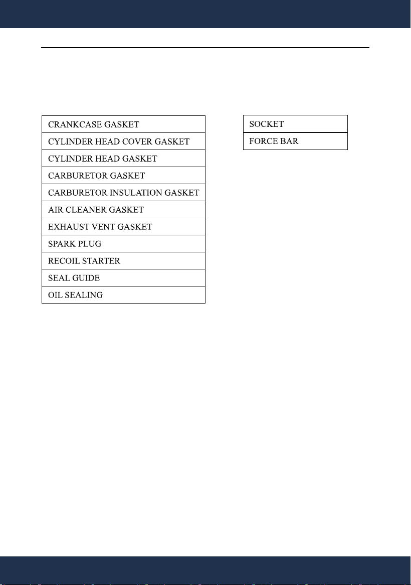
XIII.WEARING PARTS AND ACCESSORIES LIST
WEARING PARTS: ACCESSORIES:
28
WEARING PARTS AND ACCESSORIES LIST

CUSTOMER SERVICE
If you have any questions about ordering our outdoor furnitures and replacement parts or other furniture
products, please feel free to contact us using the following contact information:
Customer Service and Technical Support
Phone: (909) 628-0880
Email: [email protected]
Hours of Operation: Monday – Friday, 9AM – 4PM (CST)
DISCLAIMER
PLEASE READ THE FOLLOWING CAREFULLY
The manufacturer and/or distributor have provided the parts list and assembly diagram in this manual for
reference purposes only. They do not make any representation or warranty to the buyer that they are qualified
to make repairs to the product or replace any parts of the product. In fact, the manufacturer and/or distributor
expressly state that all repairs and parts replacements should be undertaken by certified and licensed
technicians, and not by the buyer.
The buyer assumes all risk and liability arising from their repairs to the original product or replacement parts
or arising from their installation of replacement parts. It is strongly advised that qualified professionals handle
any repairs or replacements to ensure safety and proper functioning of the product. Improper installation and
operation may result in injury, property damage, or voiding of warranty. The manufacturer and/or distributor
shall not be held responsible for any accidents, damages, or malfunctions resulting from the buyer's
installation and operation of the product. It is essential to follow all safety guidelines and recommendations
provided in this manual and to seek professional assistance if unsure about the installation or operation
procedures.