INSTALLATION GUIDE
®
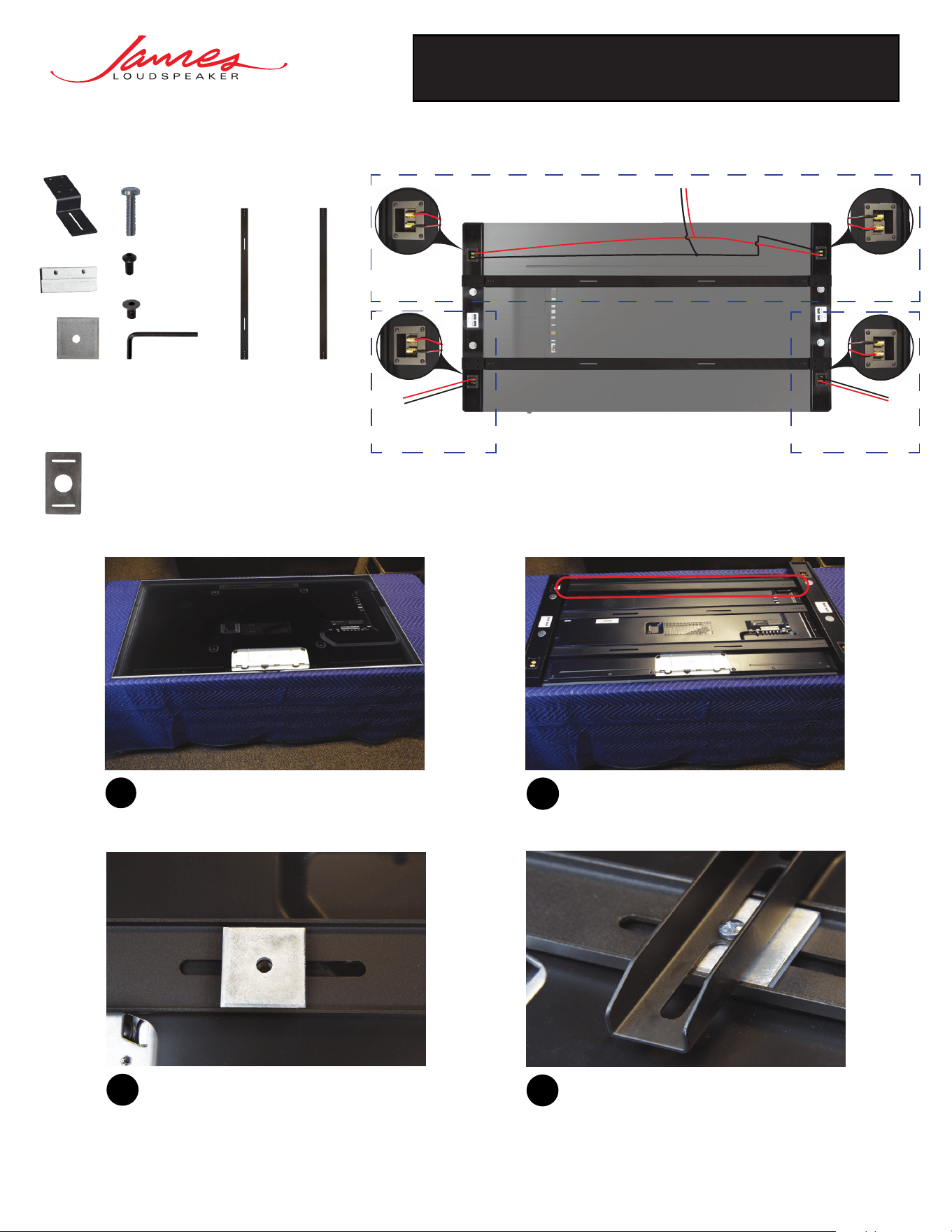
SPL CS MOUNTING BRACKET
Installation guide for James Loudspeakers SPL CS series mounting bracket.
Before proceeding, place the display on a padded
surface.
1
3
Once brackets are aligned to the VESA pattern
of the display, place U-channel spacers into
the U-channel of the bracket. This will add
additional surface area for mounting your
display’s wall brackets.
Align the SPL CS brackets to the VESA pattern on
the rear of the display. If provided, the support
bracket should be used for additional rigidity when
mounting bars.
2
Now, loosely mount the SPL CS brackets, and the
display wall mounting brackets of your choice, to
the rear of the display using the M8 or M6 screws
provided with your display.
4
Assembly Guide:
SPL CS Wiring Guide:
(Rear View)
R
Channel
Center
Channel
(Daisy Chained)
L
Channel
Required items:
Optional items:
Bar Spacer
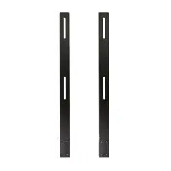
SPL CS Bracket
Support Bracket
**
U-Channel Spacer
Sliding Brackets
Holding Tabs
M8 or M6 Screw
*
UNC 8-32
Flat Head Screws
UNC 1/4”-20
Pan Head Screw
Hex Key
*
Provided with display unit
**
Required if supplied
James Loudspeaker | 535 Airpark Road, Napa, CA 94558 | 707.265.6343 | www.JamesLoudspeaker.com
®
20211008
SPL CS MOUNTING BRACKET
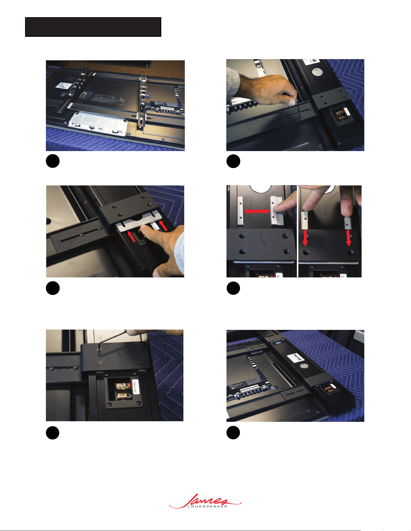
Loosely tighten the sliding bracket to the VESA
bracket using the pan head socket screws and
provided hex key.
6
Firmly tighten each of the four provided flathead
socket screws. Then finish tightening the sliding
brackets while applying constant pressure on the
SoundBar towards the display for best results.
9
Repeat these steps for the opposite side. Complete
the bracket installation by tightening any remaining
loose fasteners.
10
8
Place holding tabs on the rear of the SoundBar
and insert them into the mounting channel. Then
align the mounting tab’s threaded holes to the
countersunk holes of the sliding bracket.
If desired, the bar spacers can be added to
adjust the offset the SoundBar by inserting the
bar spacer between the sliding bracket and the
rear of the SoundBar.
7
5
Repeat step 4 until each SPL CS bracket and
the TV mount is loosely mounted to the TV’s
VESA pattern.