SBXL-100 SOUNDBAR
QUICKSTART GUIDE
BOX CONTENTS
• SBXL-100 Soundbar Quickstart Guide
• UA Series 2-125 Amplifier Quickstart Guide
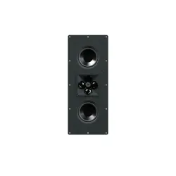
• Sonance SBXL-100 Soundbar
• Power Cord
• 1/32”, 1/16”, 1/8”, and 1/4” Shims
• Straight Edge Alignment Template with Level
• Two (2) Z-Brackets
• Ten (10) Mounting Screws
BEFORE YOU BEGIN
IMPORTANT, TEAM LIFT REQUIRED:Two or more
people must assist with installation. Never release the
soundbaruntil you confirm it is securely mounted.
Always have multiple peopleholding the bar when
removing it from the wall.
IMPORTANT, SAFE MOUNTING: The SBXL-100
Z-brackets are designed for 16” on-center stud
construction with adjustable positioning for 11” to 24”
spacing between studs. Each bracket must be secured
to two or more studs for safe installation.
IMPORTANT, ELECTRICAL REQUIREMENTS: The SBXL-
100 requires connection to a power outlet. Sonance
doesnot recommendrunning high-voltage power cords
through walls. Plan ahead. Have an electrician install an
outlet behind the SBXL-100 Soundbar to provide power
before beginning installation.
CAUTION: The SBXL-100 grille features multiple strong
magnets. Use caution when attaching or removing the
grille from the soundbar.
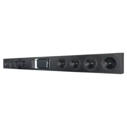
Figure 1: Relative Position of the Alignment Template
to the Back of the SBXL-100 Soundbar
Align with the level bubble centered to keep
the two Z-Bracketsa in a straight, level line.
Wall Z-Bracket Mounting Range
Speaker Area
Alignment Template
Cable Entry Hole
SBXL-100 Soundbar Back View
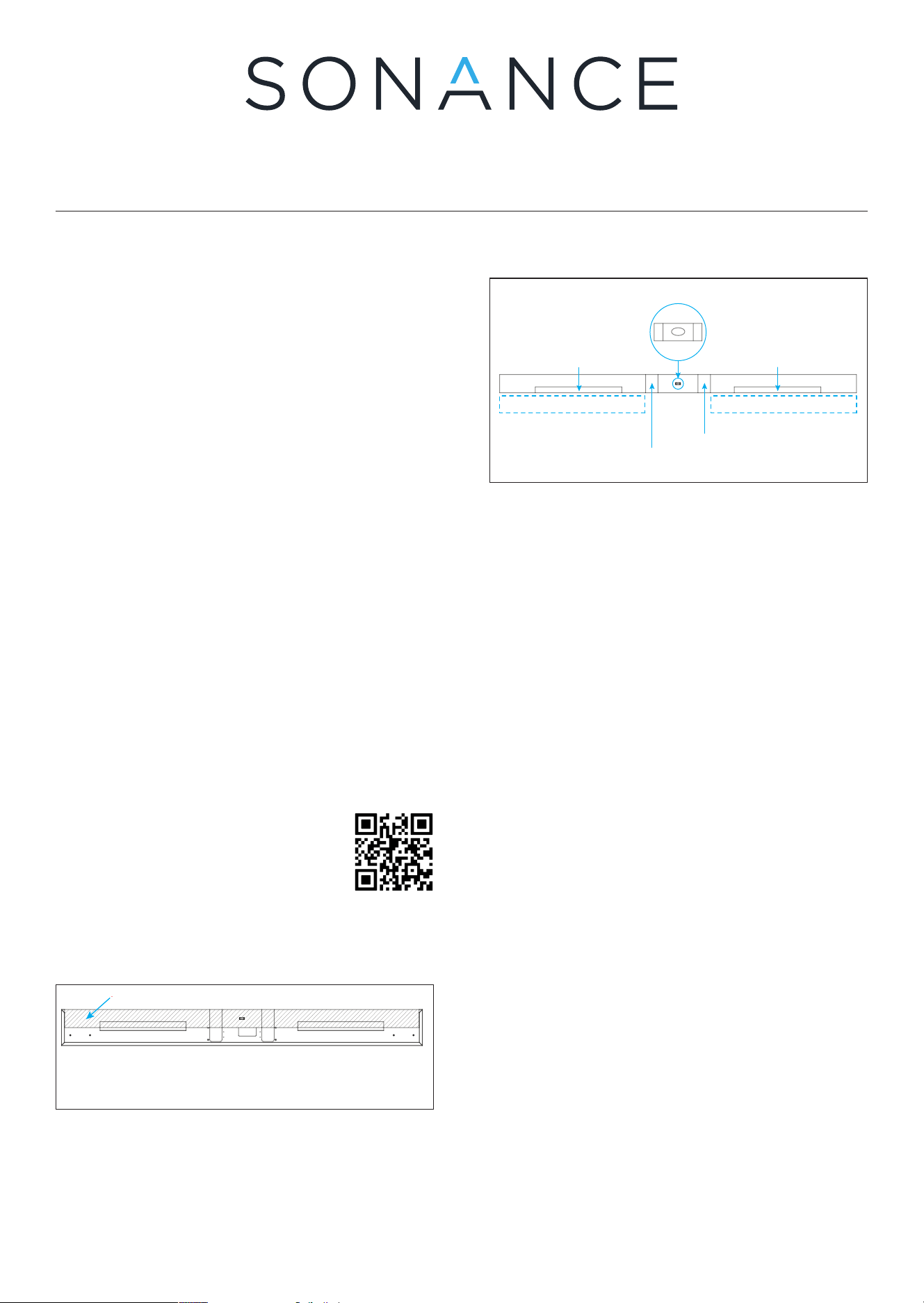
Level the template until
the bubble is centered
Wall Z-Bracket Mounting Range
Alignment Board
Relative Position of the Alignment Board on the Speaker
Soundbar-Mounted
Z-Bracket
HDMI Knockout
Power Cord Knockout
HDMI Power outlet
1. Attach brackets to wall 2. Remove template 3. Cut surface for connections
Soundbar-Mounted
Z-Bracket
Wall Z-Bracket Mounting Range
Figure 2: Alignment Template Zones
1. Carefully remove the grille from the soundbar and
set aside. The grille contains strong magnets. Keep
fingers clear when separating to avoid pinching.
2. Hold the Alignment Template against the wall in
the desired position of the SBXL-100 Soundbar,
aligning the top of the template with the desired
height of the soundbar. Be sure it is oriented with
the two Z-Bracket markings facing downward so
they appear on the bottom edge of the Alignment
Template (see Figure 2).
NOTE: When mounting below a TV that is already
mounted, allow at least 2” (50mm) above the top of
the Alignment Template to provide enough clearance
to lower the SBXL-100 Soundbar onto its Z-Bracket.
3. Adjust the Alignment Template’s positioning until
the the bubble in the level is centered, indicating the
template is level on the wall (see Figure 2).
4. Use two provided screws to secure the Alignment
Template to the wall anywhere on its surface.
5. Use a stud finder to locate studs along the width of
the Alignment Template and mark their locations
along the bottom edge.
6. Refer to Figure 2. Note the bottom edge of the
template with the two outlined Z-bracket areas.
The bottom edge of the template will meet the top
edge of the Z-Brackets. The Z-Brackets will need to
be mounted within the two dotted areas below the
template as marked in Figure 2.
7. Identify the two knockout locations to the left and
right of the bubble level on the Alignment Template
(see Figure 2). Mark the size and locations for these
two areas on the wall along the bottom of the
Alignment Template. This will help identify where to
cut the surface for wiring low voltage connections
(the left portion), and placement for an electrician
to install an outlet for power (the right portion).
8. Place one Z-bracket along the bottom edge of
the Alignment Template with the screw hole edge
facing downward and flat against the wall. The top
portion of the bracket will hover o the wall.
9. Move the Z-bracket into position along the bottom
edge of the Alignment Template, in line with the left
rectangular outline. Make sure that the top edge
of the bracket touches the bottom edge of the
Alignment Template, but do not overlap.
10. Move the bracket left or right as needed to align
the mounting holes with the stud locations. It is
okay if the bracket does not perfectly match the left
and right boundaries of the left rectangular outline
markings, but it should not extend outside of the
physical boundary width of the Alignment Template.
NOTE: The SBXL-100 Soundbar features
in-app setting adjustments for its built-in
Sonance UA Series amplifier (see the full
manual for details). Scan the QR Code to
get the app.
INSTALLATION
The alignment template ensures level Z-bracket
mounting. Its top edge represents the final soundbar
position (see Figure 1).
Scan QR Code for full installation,
connection, and setup steps.
NOTE: Bracket placement is flexible and can be moved
left or right along the alignment template as long as
they remain within the overall width and are secured to
studs.
11. Once in position, use four provided screws to
secure the Z-bracket to the wall, making contact
with at least one stud location.
12. Repeat steps 7 through 10 for the second Z-bracket
along the bottom edge of the right side of the
Alignment Template.
13. Once both Z-brackets are mounted to the wall,
remove the two screws in the Alignment Template
to remove the template from the wall.
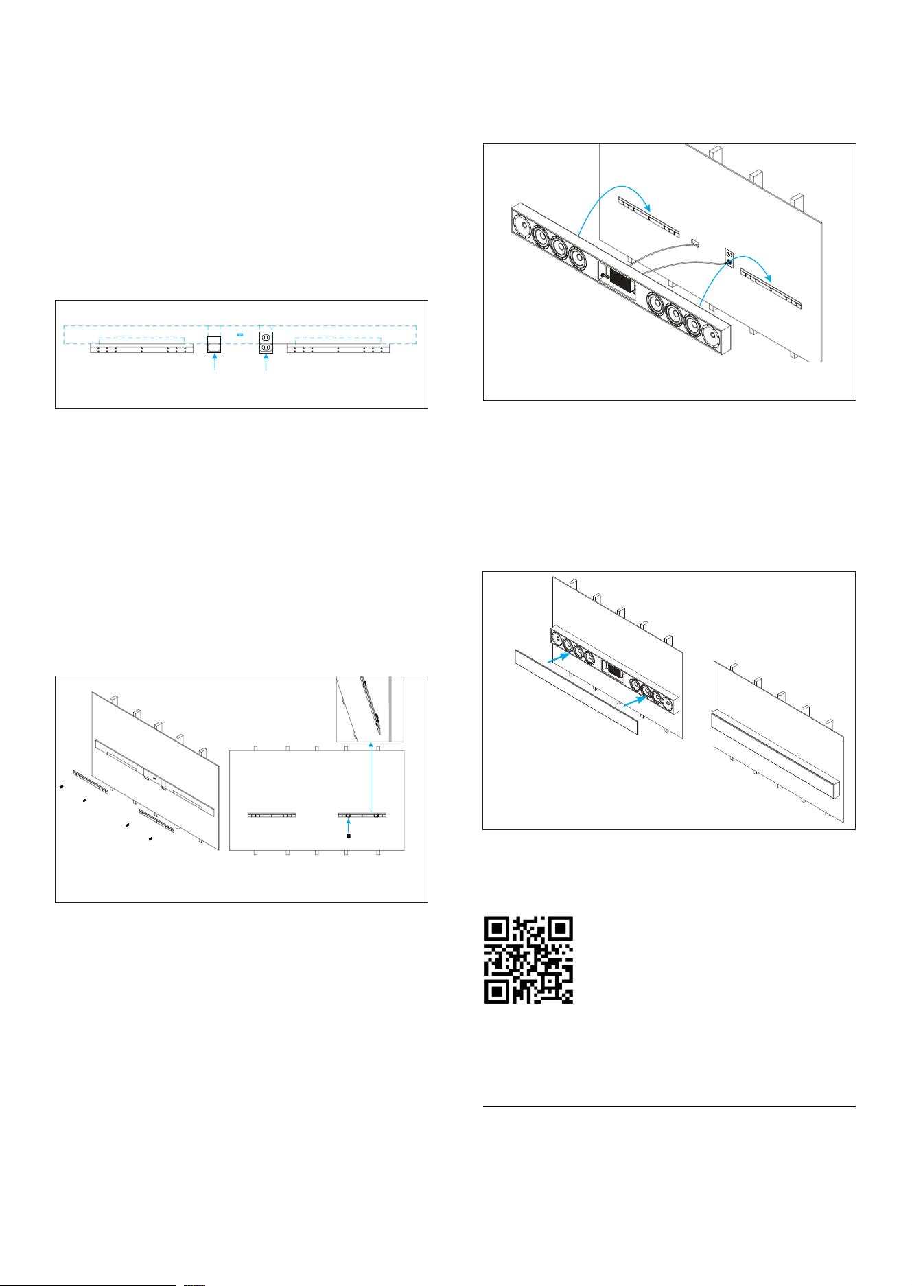
Figure 6: Carefully
Attach the Grille
Figure 5: Connect the Soundbar and Mount
onto the Z-Brackets
Lift, and then
lower into position
Power Outlet
NOTE: Bracket placement can slide left or right along
the alignment template as long as they remain within
the overall width and are secured to studs.
17. Cut a hole in the wall for low voltage wiring (HDMI,
sources) using the knockout markings as guides.
The SBXL-100 connections are located within the
left soundbar knock out.
NOTE: Only run low-voltage cables through walls.
High-voltage cables must not be run through walls.
18. Run the HDMI through the wall opening, running
from the left knock out location, exiting the wall
at the TV location above. Connect the HDMI at the
TV end into the TV input.
19. Secure the SBXL-100 Soundbar to the brackets on
the wall by lifting the soundbar above the bracket
height and then slowly lowering it until the back of
the soundbar catches the edge of both Z-brackets
along the top edge.
NOTE: Ensure both sides of the soundbar are securely
engaged before releasing. Do not bend the grille when
placing onto or removing from the soundbar.
21. Connect the HDMI from the left knock out opening to
the HDMI input inside the SBXL-100 left knock out.
CAUTION: The SBXL-100 grille features multiple strong
magnets. Use caution when attaching or removing the
grille from the soundbar.
Figure 4: Secure the Z-Brackets on the Wall
SHIM
Insert the shims to get the two wall Z-brackets to be straight on a wall that is not straight
20. Plug the power cord into the SBXL-100 and the
outlet through the right knock out. Sonance
recommends having an electrician install an outlet
directly behind the SBXL-100 Soundbar, within the
area behind the right knockout (see Figure 5).
Figure 3: Wall Elements Relative to Template
Level the template until
the bubble is centered
Wall Z-Bracket Mounting Range
Alignment Board
Relative Position of the Alignment Board on the Speaker
Soundbar-Mounted
Z-Bracket
HDMI Knockout
Power Cord Knockout
HDMI Power outlet
1. Attach brackets to wall 2. Remove template 3. Cut surface for connections
Soundbar-Mounted
Z-Bracket
Wall Z-Bracket Mounting Range
14. Place the Alignment Template on its edge against
the face of both Z-brackets. Check for areas where it
misses contact with the bracket. The goal is for the
Z-brackets to be evenly aligned with one another,
touching all along the edge of the Alignment
Template, as straight as possible.
15. Mark the areas along the width where there are gaps
between the Alignment Template and the brackets.
16. Insert the provided shims behind the BOTTOM
of each Z-bracket at the marked locations. This
pushes the bracket away from the wall, creating the
clearance needed at the bracket’s top edge for the
soundbar brackets to slide into position along its
full length.
22. Carefully attach the magnetic grille to the
soundbar (see Figure 6).
LIMITED (2) YEAR WARRANTY Sonance warrants to the first end-user purchaser
that this Sonance-brand product (“Product”), when purchased from an authorized
Sonance Dealer/Distributor, will be free from defective workmanship and materials
for the life of the Product, except for the grille, which is warranted for one (1) year.
Sonance will at its option and expense either repair the defect or replace the Product
with a new or remanufactured Product or a reasonable equivalent. ©2026 Sonance.
All rights reserved. Sonance is a registered trademarks of Dana Innovations. Due
to continuous product improvement, all features and specifications are subject to
change without notice. For the latest Sonance product specification information
visit our website at www.sonance.com. 991 Calle Amanecer • San Clemente, CA
92673 USA • Phone: (949) 492-7777 03.13.2026