POOL CARTRIDGE FILTER 425SQF
SAVE THIS MANUAL: KEEP THIS MANUAL FOR SAFETY WARNINGS, PRECAUTIONS, ASSEMBLY,
OPERATING, INSPECTION, MAINTENANCE AND CLEANING PROCEDURES. WRITE THE PRODUCT’S
SERIAL NUMBER ON THE BACK OF THE MANUAL NEAR THE ASSEMBLY DIAGRAM (OR MONTH
AND YEAR OF PURCHASE IF PRODUCT HAS NO NUMBER)
OWNER’S MANUAL AND SAFETY INSTRUCTIONS
ITEM: 75202
FOR QUESTIONS PLEASE CALL OUR CUSTOMER SUPPORT: 909.628.0880 MON-FRI 9AM TO 3PM PST

IMPORTANT SAFETY INFORMATION
1
GENERAL SAFETY WARNINGS
THE WARNINGS, PRECAUTIONS, AND INSTRUCTIONS DISCUSSED IN THIS INSTRUCTION
MANUAL CANNOT COVER ALL POSSIBLE CONDITIONS AND SITUATIONS THAT MAY OCCUR. IT
MUST BE UNDERSTOOD BY THE OPERATOR THAT COMMON SENSE AND CAUTION ARE FACTORS
WHICH CANNOT BE BUILT INTO THIS PRODUCT, BUT MUST BE SUPPLIED BY THE OPERATOR.
READ CAREFULLY AND UNDERSTAND ALL ASSEMBLY AND OPERATION INSTRUCTIONS BEFORE
OPERATING. FAILURE TO FOLLOW THE SAFETY RULES AND OTHER BASIC SAFETY PRECAUTIONS
MAY RESULT IN SERIOUS PERSONAL INJURY.
• Do not operate water circulation system if a system component is assembled improperly,
damaged, missing, or not a genuine Hayward component.
• Before performing maintenance on the water circulation system, verify all system and pump controls
are in OFF position and filter manual air relief valve is in the OPEN position.
• Never rely on hand tightening the clamp nut to the clamp bolt. Using a ¾” socket on a torque
wrench, torque clamp nut and clamp bolt to 150 inch-lbs.
• Before starting system pump, insure filter manual air relief valve body is in LOCK position in filter
upper body.
• Before starting the system pump, verify that all system valves are set in a position to allow water from
the filter to return back to the pool.
• Before starting the system pump, the manual air relief valve must be in the OPEN position.
• When starting pump, do not stand over or near filter.
• If water leakage appears in the area of the filter tank clamp, immediately turn off all system
circulation pumps and electrical power. Do not return to the filter until all water flow has stopped.
Reassemble the clamp system per the instructions in this owner’s manual to stop the leak.
• Return to filter to close manual air relief valve only when a steady stream of water (Not air or air and
water
mix) is discharged from the manual air relief valve.
To reduce the risk of injury, do not permit children to use or climb on this product. Closely supervise
children at all times. The ANSI/NSPI-4 Standars (above ground and on ground pools advise that
components such as the filtration system, pumps and heaters be positioned to prevent their being
used as a means of access to the pool by young children.
Pool and spa water circulation systems operate under hazardous pressure during start up, normal
operation, and possibly after pump shut off. Pressure in system can cause explosive component
separation of the upper filter body if safety and operation instructions are not followed. Severe personal
injury or death can result.
This product should be installed and serviced only by a qualified pool professional.
TO AVOID COMPONENT SEPARATION
Follow all safety and operation instructions.
• Do not change filter control valve position while system pump is running.
EXCESS PRESSURE HAZARD
Pressure testing of the pump and filter system in excess of the 50 PSI can cause explosive separation
of the components. Component separation can result in severe personal injury or death.

IMPORTANT SAFETY INFORMATION
2
WARNING ELECTROCUTION HAZARD
High Voltage electricity is present in the pool and spa equipment. High voltage electricity can cause shock
and electrocution. Shock and electrocution can result in severe personal injury or death.
• All electrical wiring MUST be in conformance with applicable local codes, regulations and the National
Electrical Code (NEC).
• Before performing any service or maintenance on electrical equipment turn off all electrical power.
• Contact a licensed electrician or building inspector for information on local electrical codes for bonding
requirements.
• Verify water discharge from the lter manual air relief valve is directed away from electrical devices. Do
not locate pump controls over or near lter.
WARNING – SUCTION ENTRAPMENT HAZARD
Suction in suction outlets and/or suction outlet covers that are, damaged, broken, cracked, missing, or
unsecured can cause severe injury and/or death due to the following entrapment hazards:
Hair Entrapment- Hair can become entangled in suction outlet cover.
Limb Entrapment- A limb inserted into an opening of a suction outlet sump or suction outlet cover that is
damaged, broken, cracked, missing, or not securely attached can result in a mechanical bind or swelling
of the limb.
Body Suction Entrapment- A negative pressure applied to a large portion of the body or limbs can result
in an entrapment.
Evisceration/ Disembowelment Entrapment- A negative pressure applied directly to the intestines
through an unprotected suction outlet sump or suction outlet cover that is, damaged, broken, cracked,
missing, or unsecured can result in evisceration/ disembowelment entrapment.
Mechanical Entrapment- There is potential for jewelry, swimsuit, hair decorations, nger, toe or knuckle
to be caught in an opening of a suction outlet cover resulting in mechanical entrapment.
TO REDUCE THE RISK OF ENTRAPMENT HAZARDS:
• A minimum of two functioning suction outlets per pump must be installed. Suction outlets in the same
plane (i.e. oor or wall), must be installed a minimum of three feet (3’) [1 meter] apart, as measured from
near point to near point.
• Dual suction outlets shall be placed in such locations and distances to avoid “dual blockage” by a user.
• Dual suction outlets shall not be located on seating areas or on the backrest for such seating areas.
• The pool or spa circulation system shall be designed to comply with ANSI/APSP-7 2006.
• Suction outlet covers shall conform to ANSI/ASME A112.19.8
• Never use Pool or Spa if any suction outlet component (cover/grate) is damaged, broken, cracked,
missing, or not securely attached.
• Immediately replace damaged, broken, cracked, missing, or not securely attached suction outlet
components.
• The CPSP as well as the ICC International Residential Code Part IX, Appendix G, Section AG106 species
the installation of a safety vacuum release system conforming to ASME A112.19.17, or an approved gravity
drain system.
• Failure to remove pressure test plugs and/or plugs used in winterization of the pool/spa from the suction
outlets can result in an increased potential for suction entrapment.
• Failure to keep suction outlet components clear of debris, such as leaves, dirt, hair, paper and other
material can result in an increased potential for suction entrapment.
INSTALLATION
3
WARNING: This product should be installed and serviced only by a
qualied pool professional.
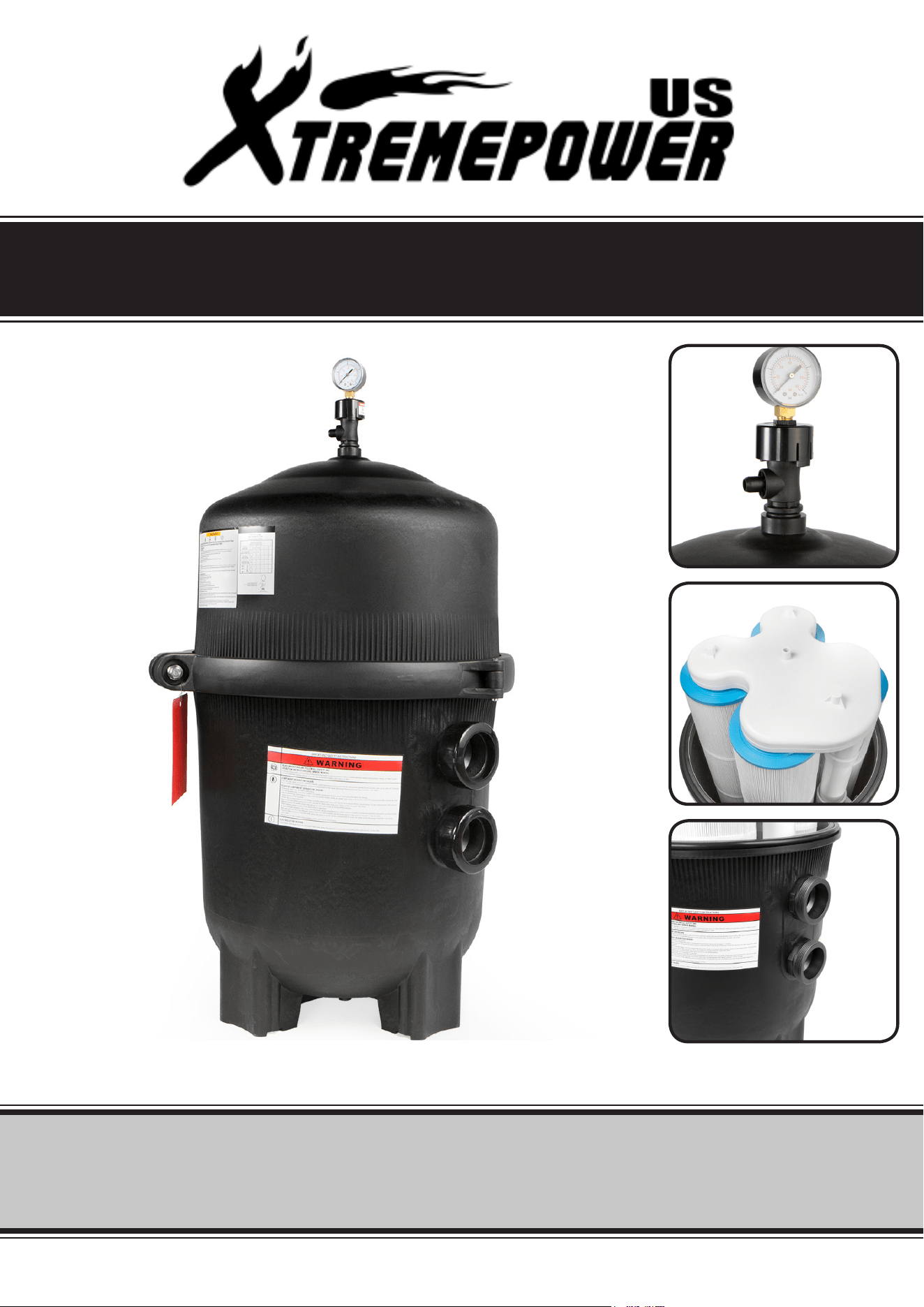
1. The filter system should be installed on a
level concrete slab or other rigid base. Select a
well drained and vented area, one that does not
flood when it rains. Position the filter so that
the piping connections, and winter drain are
convenient and accessible for operation,
service, maintenance and winterizing.
2. Position filter body such that all operation
and safety labels are visible.
3. Position filter so the filter will drain by gravity.
4. If practical, place pump and filter in the shade to
shield it from continuous, direct heat from the sun.
6. Connect the pump discharge (pump OUTLET) to
the top port of the filter (filter INLET).
7. Connect the bottom filter port (filter OUTLET) to
the pool return plumbing lines.
8. Do not locate pump controls over or near
filter.
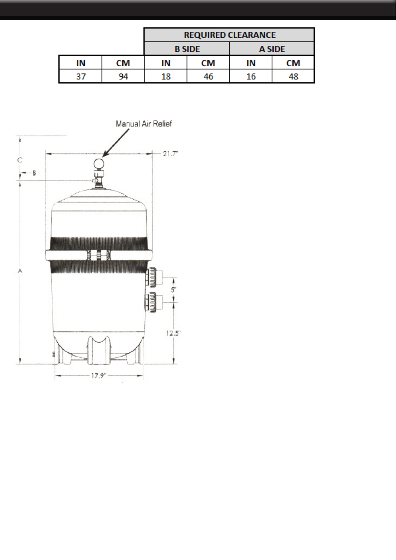
1. Use ONLY original components; Non-original components may fail in use and cause explosive component
separation. Verify that upper and lower lter bodies are properly secured with the lter body clamp. Never rely
on hand tightening the clamp nut to the clamp bolt. Using a ¾” socket on a torque wrench, torque clamp nut
to clamp bolt to 150 inch-lbs. (See Fig 1) Verify that the lter manual air relief body is in the LOCK position,
and no lter components are missing, damaged or not genuine components. (See Fig 2)
STARTING THE PUMP and FILTER SYSTEM
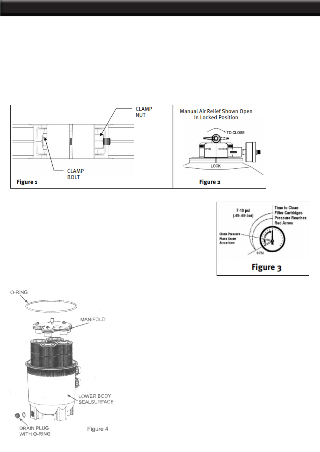
2. Close lter drain. NOTE: Filter plug requires an o-ring seal. (See Fig 4)
3. Open all system valves to allow water from the pool to the ltration system and from the lter to return to
the pool.
OPERATION
4
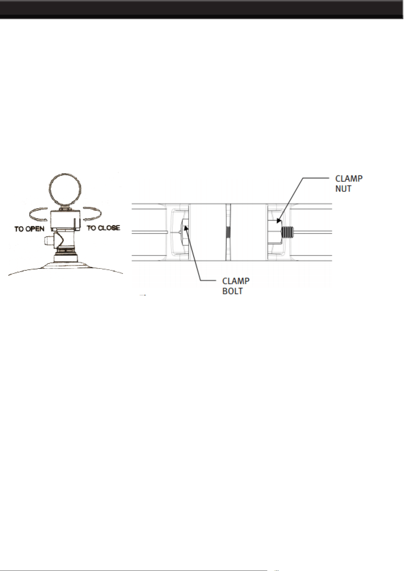
4. Place the manual air relief valve in OPEN position. (See Fig 2)
1. When starting system pump, do not stand over or near lter. If water leakage appears at lter tank clamp,
immediately turn off all system circulation pumps and all electrical power. Do not return to the lter until all
water leakage has stopped.
STARTING THE PUMP
2. Reassemble the clamp system per the instructions on page 7 in this owner’s manual to stop leak. 2. Return
to lter to CLOSE manual air relief valve only when a steady stream of water (not air or, air and water mix) is
discharged from the manual air relief valve.
FILTERING
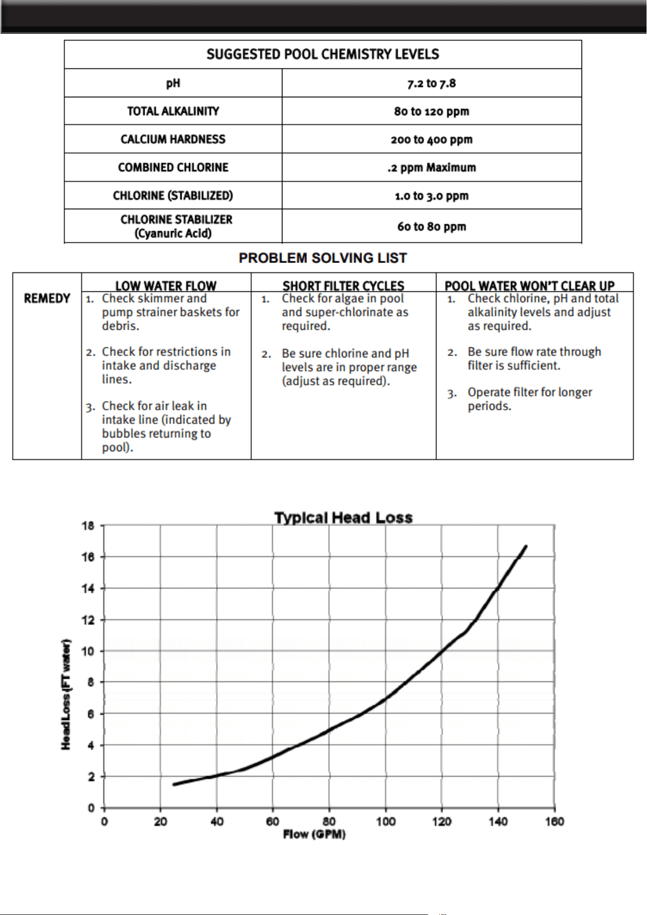
Filtration starts as soon as ow is steady through the lter. As the
lter removes dirt from the pool water, the accumulated dirt causes a
resistance to ow. As a result, the gauge pressure will rise and the ow
will decrease. When the pressure rises between 7 and 10 psi (.49 - .69
bar) above the starting pressure, or when the ow decreases below
the desired rate, clean or replace the lter cartridge elements. Once
your lter is running and there is a pressure reading, line up the green
arrow with the current reading. (See Fig 3) When the pressure rises
to or above the red or second arrow, it is time to clean or replace your
lter cartridge elements.
By recording the initial starting pressure (with clean lter
elements) a determination can be made when the lter cartridge
elements should be replaced rather than cleaned. After the
lter elements have been cleaned and reinstalled if the starting
pressure is higher than 6 PSI above the starting pressure with
the new lter cartridge elements, the lter cartridge elements
should be replaced the next time the gauge arrow reaches the
red arrow.
This product should be installed and serviced only by a qualied
pool professional.
OPERATION
1. Turn off all system circulation pumps and all electric power on the equipment pad.
2. Set all system valves in a position to prevent water ow to the lter.
3. The manual air relief valve must be placed in the OPEN position. (Fig 6)
4. Remove lter drain plug (Fig 4) and drain water from lter.
5. Using 3/4” wrenches or hex sockets, loosen and remove the clamp nut and the clamp bolt. (Fig 5)
6. Holding both ends of the lter clamp carefully spread the clamp ends. Remove the clamp by lifting over
the upper lter body. Do not to drop the clamp during removal, because the clamp could be damaged. Do not
strike the clamp with metal tools as they can damage the clamp.
7. Lift off upper lter body. Do not use the pressure gauge to lift the upper lter body.
FILTER DISASSEMBLY INSTRUCTIONS
MANUAL RELIEF SHOWN OPEN
REMOVING CARTRIDGES
1. Remove the top Manifold, which is exposed when the upper lter body is removed. (Fig 4)
2. Remove the lter cartridge elements by using slight rocking motion and lifting up.
3. Clean lter cartridge elements.
CLEANING CARTRIDGES
The Cartridge lter element can be cleaned by washing inside and outside with a garden hose. After hosing
cartridge, for best results, carefully brush the pleated surface to remove ne particles. Do not pressure wash
as it can damage the lter element. You may nd some debris on the cartridge pleats, which may not have
been removed with hosing.
RE-INSTALLING CARTRIDGES
1. Flush and drain any dirt or debris from the bottom of the lower lter body.
2. Flush any dirt or debris from the upper lter body and from around the manual air relief area.
3. Carefully replace the cartridges over the hubs on the bottom seal plate.
4. Place top manifold securely on top of cartridges, aligning the return pipe with the port in the manifold.
5
OPERATION
6
CLAMP BOLT
ROUNDED END OF NUT
CLEAN SEAL RING AND SEAL SURFACE
1. Remove lter tank seal.
2. With a clean cloth, wipe the lower lter body seal surface and
clean seal of all dirt and debris. (Fig 4) Do not use a solvent.
3. With a clean cloth wipe the upper lter body seal surface.
NOTICE:
• Do not use any petroleum solvents to clean lter components.
• Do not lubricate seal.
WARNING
This product should be installed and serviced only by a
qualied pool professional.
BODY AND CLAMP RE-ASSEMBLY
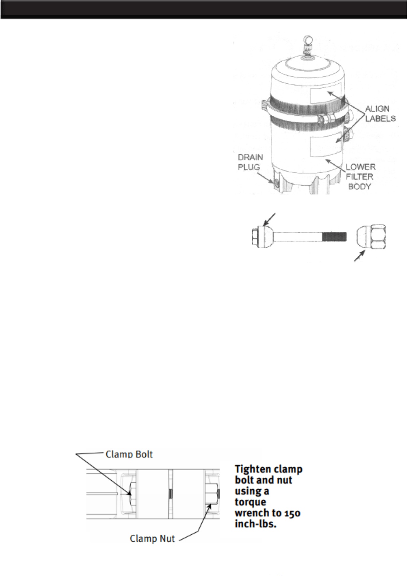
1. Place the metal reinforced seal on lower lter body. (Fig 4) Place upper lter body on metal reinforced seal
and lower lter body in a position which allows all operation and safety labels to be clearly visible and the
upper lter body to be centered on the lower lter body. Press down rmly and evenly on the upper lter body
to seat the seal. (Fig 7)
2. Replace the lter clamp around the upper and lower lter bodies. Hold the clamp ends to position the clamp
on the lter bodies with the clamp ends adjacent to the safety and operation labels on the lter bodies. (Fig 7)
3. Insert clamp bolt through the clamp ends and thread the clamp nut onto clamp bolt with rounded end of the
nut (Fig 8) towards the ends of the clamp. 4. Never rely on hand tightening of clamp nut to clamp bolt. Using
a 3/4” socket on a torque wrench, torque clamp nut to clamp bolt to 150 inch-lbs. (Fig 9)
4. Never rely on hand tightening of clamp nut to clamp bolt. Using a 3/4” socket on a torque wrench, torque
clamp nut to clamp bolt to 150 inch-lbs. (Fig 9) DO NOT HIT OR STRIKE CLAMP WITH HAMMER OR METAL
TOOLS.
5. Follow Operation Instructions for “Starting the Pump and Filter System” (Page 5).
OPERATION
7
REMOVING THE MANUAL AIR RELIEF VALVE
This product should be installed and serviced only by a qualied
pool professional. Your Filter comes with a Manual Air Relief
Valve (MAR) pre-installed from the factory. For Qualied pool
professionals only: If MAR valve needs to be serviced, follow
these instructions carefully.
1. Turn off all system circulation pumps and all electric power on
the equipment pad.
2. Set all system valves in a position to prevent water from
owing to the lter.
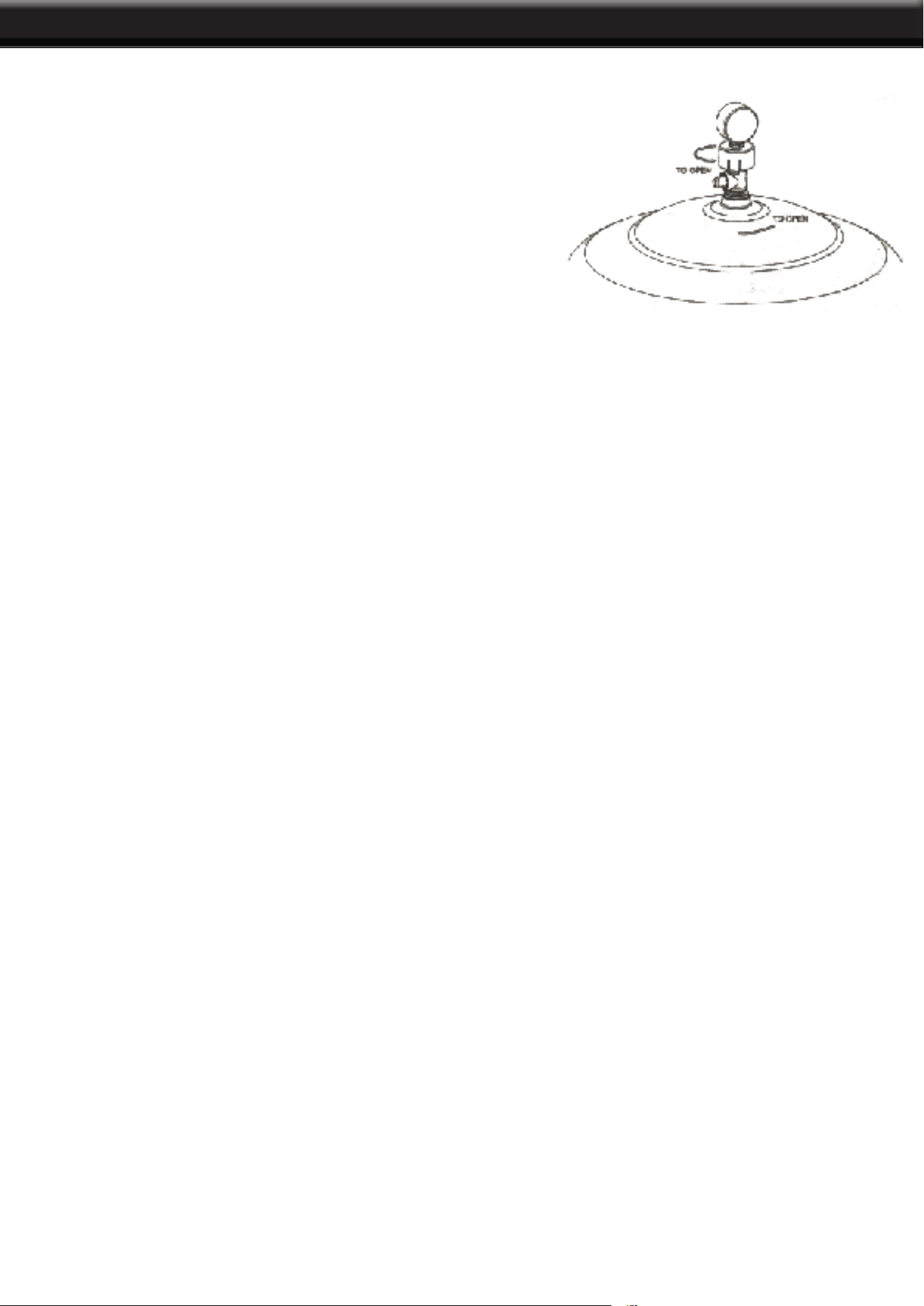
3. The manual air relief valve must be placed in the OPEN
position.
4. Wait until all water leakage has stopped.
5. The air valve relief valve can be removed by screwing the
whole part counter-clockwise.
1. Check the o-ring seals, replace as needed.
2. With a clean cloth, wipe upper lter body and o-ring groove. Remove all dirt and debris.
3. Align the notch in the MAR Flange with notch on top of the upper lter body.
4. Press the MAR straight down into the upper lter body.
5. Turn the MAR clockwise until the indicator is aligned with the “LOCK” position on the upper lter body.
6. Verify the MAR discharge points away from all electrical connections.
RE-INSTALLATION OF THE MANUAL AIR RELIEF VALVE
WINTERIZING FILTER
This product should be installed and serviced only by a qualied pool professional.
In areas where sub-freezing temperatures can be expected, the lter should be drained to protect the lter
from damage.
1. The lter should be disassembled and the lter cartridges elements cleaned or replaced.
2. Follow directions under FILTER DISASSEMBLY INSTRUCTIONS
3. Then follow REMOVING CARTRIDGES per instructions
4. Reassemble per FILTER RE-ASSEMBLY INSTRUCTIONS.
5. Be sure to leave the drain plug unattached during the winter season to avoid cracking the lter body
MAINTENANCE
8
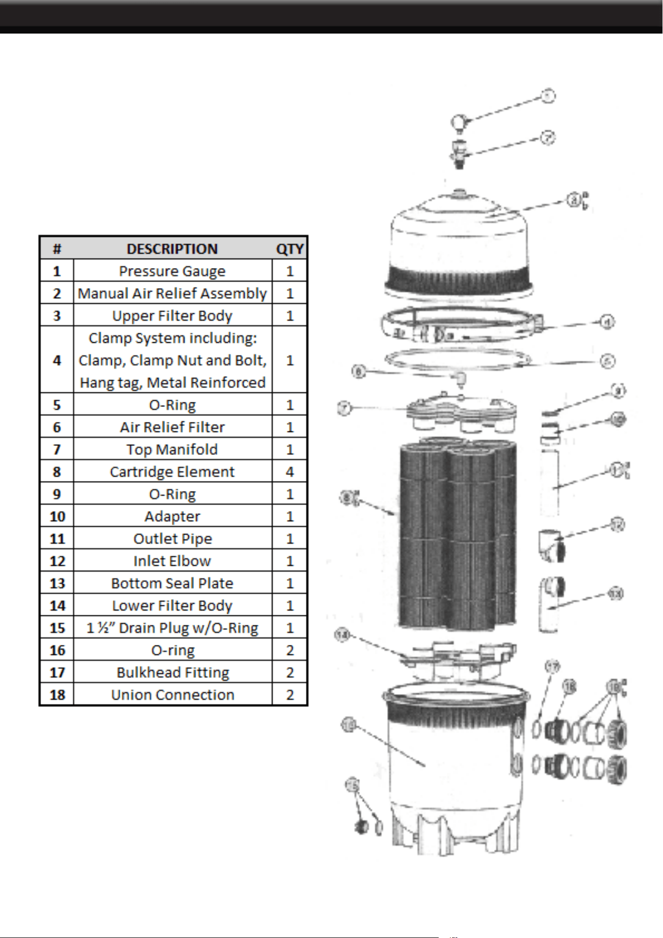
PARTS
9
10
DISCLAIMER
THE MANUFACTURER AND/OR DISTRIBUTOR HAS PROVIDED THE PARTS LIST AND ASSEMBLY
DIAGRAM IN THIS MANUAL AS A REFERENCE TOOL ONLY. NEITHER THE MANUFACTURER OR
DISTRIBUTOR MAKES ANY REPRESENTATION OR WARRANTY OF ANY KIND TO THE BUYER THAT
HE OR SHE IS QUALIFIED TO MAKE ANY REPAIRS TO THE PRODUCT, OR THAT HE OR SHE IS
QUALIFIED TO REPLACE ANY PARTS OF THE PRODUCT. IN FACT, THE MANUFACTURER AND/OR
DISTRIBUTOR EXPRESSLY STATES THAT ALL REPAIRS AND PARTS REPLACEMENTS SHOULD BE
UNDERTAKEN BY CERTIFIED AND LICENSED TECHNICIANS, AND NOT BY THE BUYER. THE BUYER
ASSUMES ALL RISK AND LIABILITY ARISING OUT OF HIS OR HER REPAIRS TO THE ORIGINAL
PRODUCT OR REPLACEMENT PARTS THERETO, OR ARISING OUT OF HIS OR HER INSTALLATION
OF REPLACEMENT PARTS THERETO.
Record Product’s Serial Number Here:
Note: If product has no serial number, record month and year of purchase instead.
Note: Some parts are listed and shown for illustration purposes only and are not available individually
as replacement parts.
PLEASE READ THE FOLLOWING CAREFULLY
PRODUCT MADE IN CHINA
