User Manual
IMC09 Banknote
IMC09
Version 1.00

Contents
1.0. Machine Overview
2.0. Unpack and Installation
2.1. What's in the Box?
1
2
2
3
3
3
4
4
4
6
6
6
7
8
8
8
9
11
11
11
9
10
10
13
14
14
15
16
16
17
17
18
19
19
20
22
22
23
24
12
12
2.2. Installation
2.2.1. Installation Warnings
2.2.2. Power Supply Connection
3.0. Display and Operational Interface
3.1. Display Appearance
3.2. Operational Instructions for Function Keys
3.3. Display Interface
4.0. Operating Instructions
4.1. Start-up
5.0. Settings
5.1. Service Menu
4.2. How to Place Banknotes?
4.3. Operating Modes
4.3.1. Auto/Manual Mode
4.3.2. Counting Mode(CNT)
4.3.3. Sorting Mode(SDC)
6.0. Software Upgrade
7.0. Maintenance and Troubleshooting
7.1. Error Code and Solution
7.2. Hopper Plate Adjustment
7.3. Common Trouble and Solution
5.1.1. Read Sensor Values
5.1.2. IR Calibration
5.1.3. MG/MT Waveforms
5.1.4. Function Setting
5.1.5. Auto Diagnostic
5.1.6. PCS Counted and Reset
5.1.7. Detection Level
5.1.8. Back to Default setting
5.2. Version Information
5.3. Time Setting
5.4. Language Selection
4.3.4. Mix Mode(MDC)
4.3.5. Batch Mode
4.3.6. ADD Mode
4.3.7. Currency Mode Selection
4.3.8. Print Data
4.3.9. Authentication level
1
Support: +1 650 206 2250
2
Support: +1 650 206 2250
1.0. Machine Overview 2.0. Unpack and Installation
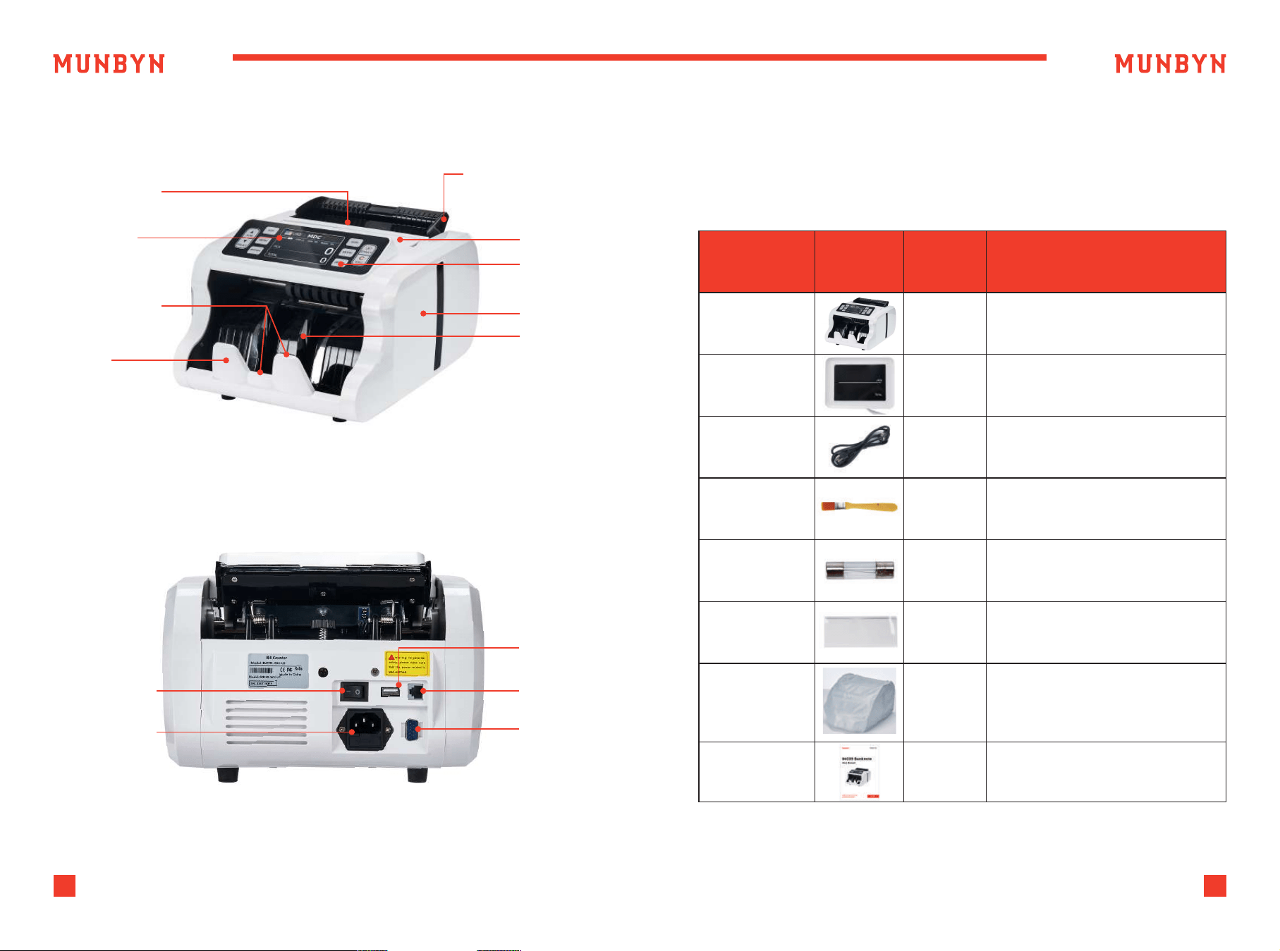
2.1. What's in the Box?
When you receive the package, open and check the packing list
in the package.
Figure 1-1 IMC09 Front Diagram
Table 2-1 What's in the Box?
Figure 1-2 IMC09 Back Diagram
Hopper Sensor
Adjustable Banknote
Guider
Handle
Panel
Side Cover
Power Switch
Power Socket
USB Port
External
Display Port
Printer Port
Impeller
TFT Display
Stacker Sensor
Stacker
Item Name
Banknote
Counter
Banknote Counter
External LED display screen
with RJ12 cable
Power supply cable of
American standard
Clean the machine
The backup fuse for the
power protection
Used for the IR calibration
Cover on the surface of the
machine to prevent dust
accumulation and machine
failure
1
1
1
1
1
1
1
External
Display
Power Cable
Nylon Brush
Fuse
IR Calibration
Paper
Dust Cover
User Manual
Picture Quantity
(pcs)
Description
3
Support: +1 650 206 2250
4
Support: +1 650 206 2250
2.2. Installation
2.2.1. Installation Warnings
2.2.2. Power Supply Connection
1) This machine is specially designed for indoor use. Please do not
install or use it outdoors.
2) Please do not install it in place that cannot bear the weight of
this product or in places that are inclined or uneven.
3) Do not use or please combustible materials, inflammables and
volatile items such as thinners around/inside this product.
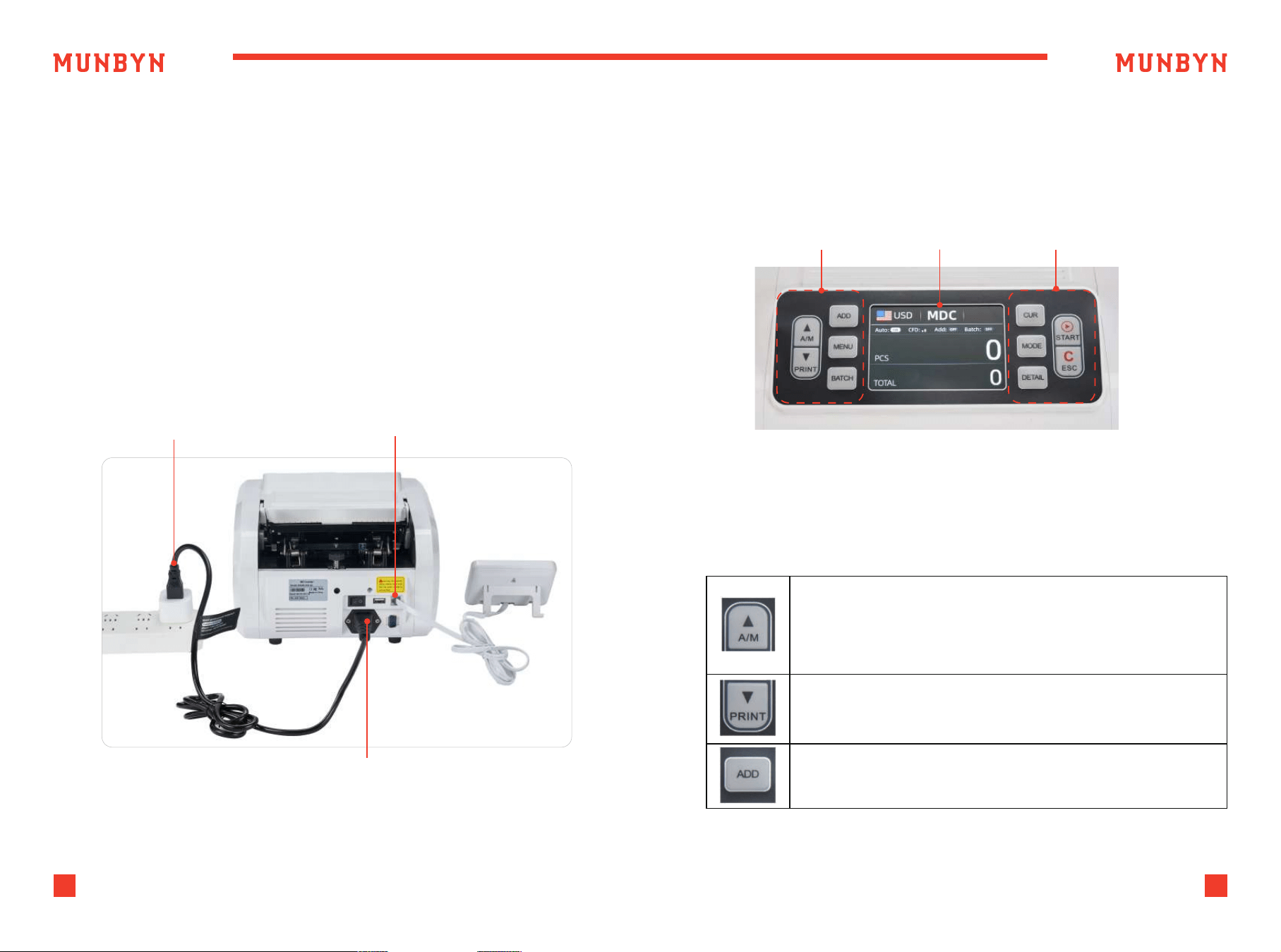
“A/M” button, press to choose MANUAL or AUTO counting mode.
In AUTO mode, counting will begin as soon as bills are placed
in the hopper.
In MANUAL mode, counting begins when the user presses
the “SATRT” button.
“PRINT” button, after connecting the printer, press this button to
print the information about cash counting.
“ADD” button, press to turn on/off the ADD function.
Figure 2-1 Power and External Display Connection
Figure 3-1 Display Appearance
Power Supply
Power Cord Connector
External Display
Connector
Operational Keys Display Area Operational Keys
3.0. Display and Operational Interface
3.1. Display Appearance
3.2. Operational Instructions for Function Keys
5
Support: +1 650 206 2250
6
Support: +1 650 206 2250
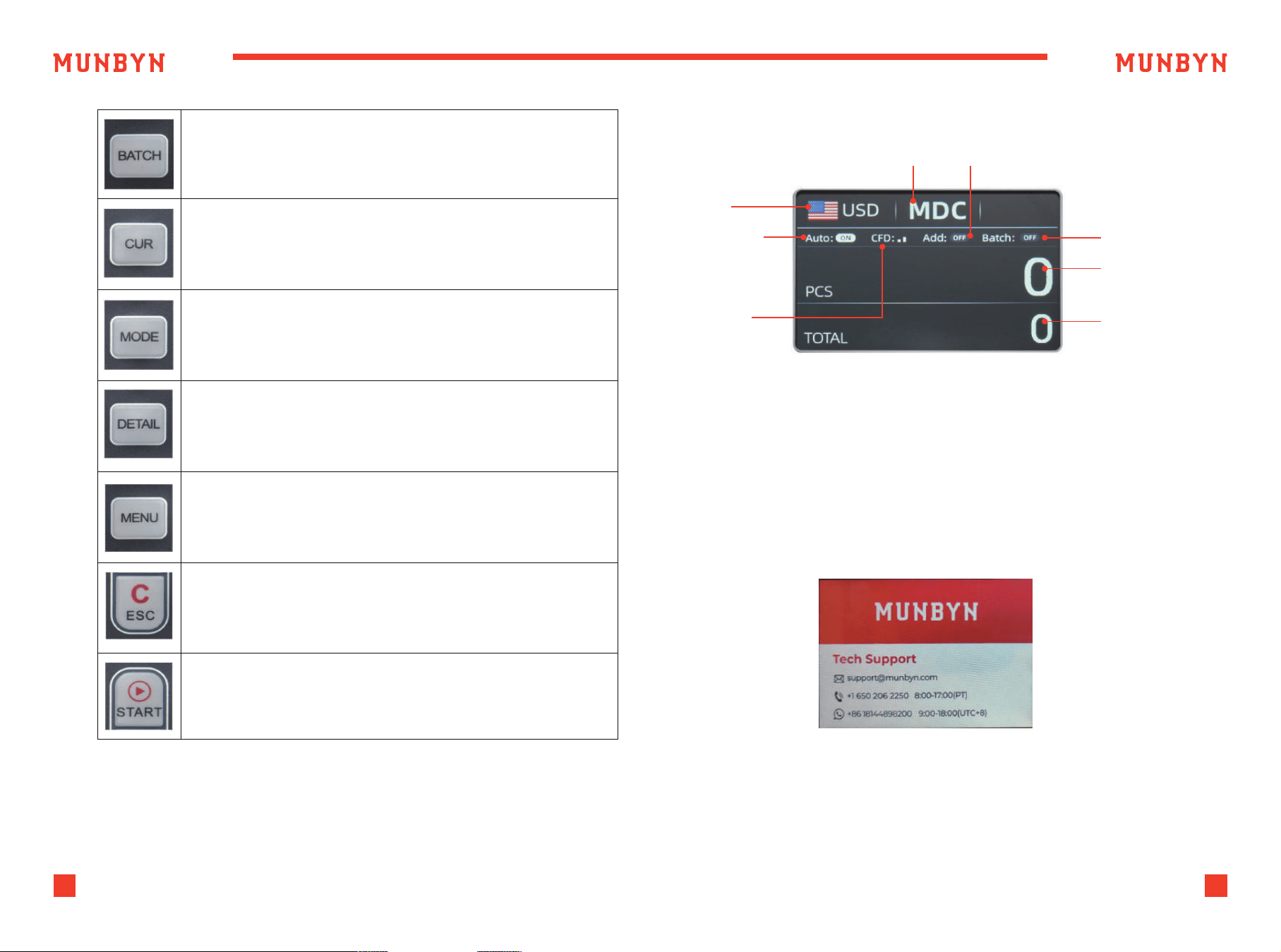
“BATCH” button, press to turn on/off the BATCH function.
“CUR” button, press to different currency counting.
“MODE” button, press to switch between different counting
modes: MDC/SDC/CNT.
Long press this button to adjust the sensitivity of counterfeit
detection.
“DETAIL” button, press to check the counting result details
“MENU” button, press this button to enter the user menu settings.
“ESC” button, press to return to the previous interface.
“START” button, press to counting or clear the current counting
information.
Table 3-1 Function Keys
Figure 3-2 Display Interface
Figure 4-1 Startup Interface
Currency
Counting Mode ADD mode
Batch number
Total number of
banknotes counted
Amount of money
counted
AUTO counting
Counterfeit
identification
leve
3.3. Display Interface
4.0. Operating Instructions
4.1. Start-up
Turn on the switch after connecting the machine to power supply. First,
the machine enters the startup interface, as shown in Figure 4-1.
When starting up, the machine will enter a self-checking state, please wait
for about 15 seconds. Please do not insert any banknotes and ensure that
there is nothing in the Hopper and Stacker.
7
Support: +1 650 206 2250
8
Support: +1 650 206 2250
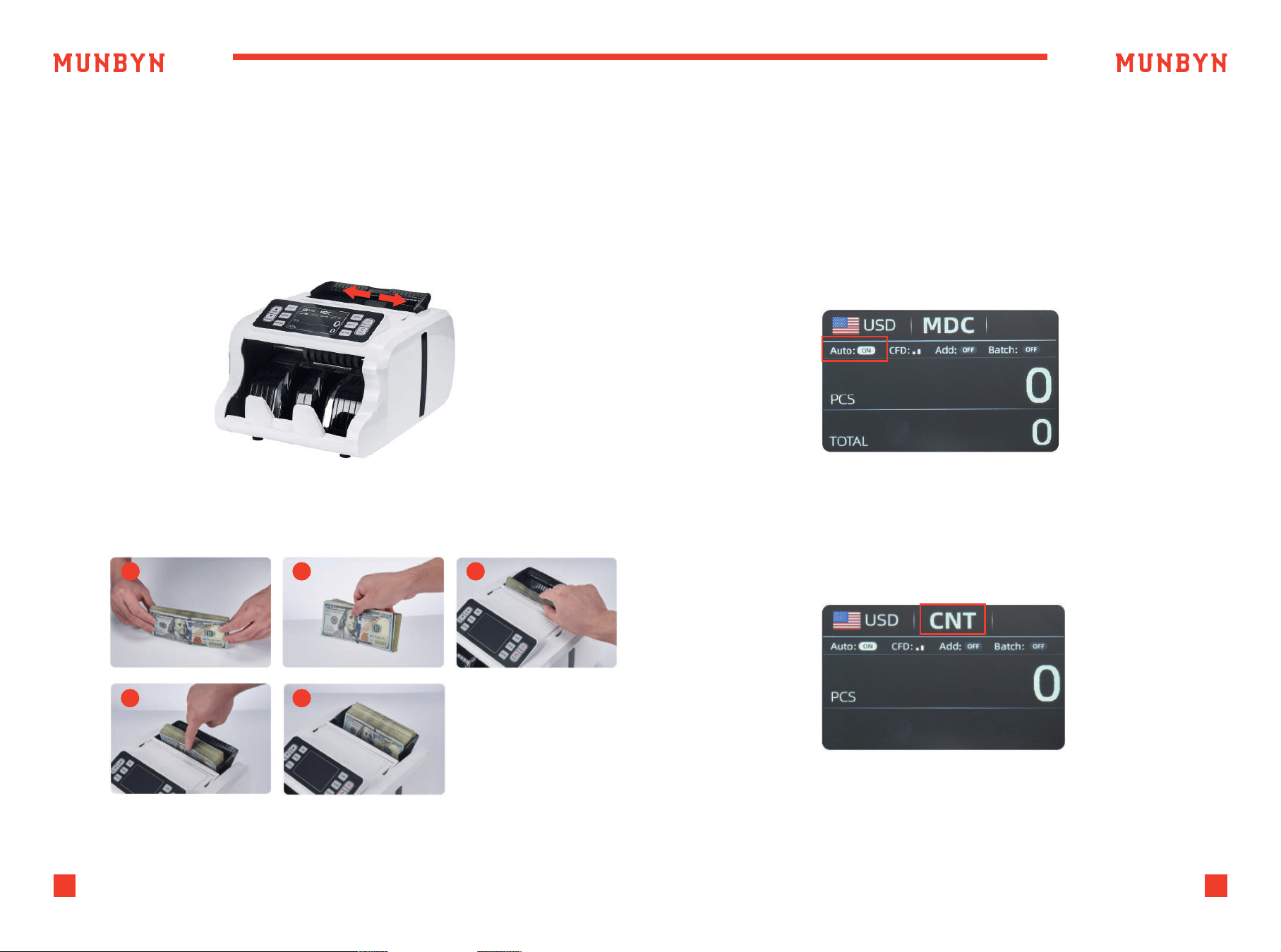
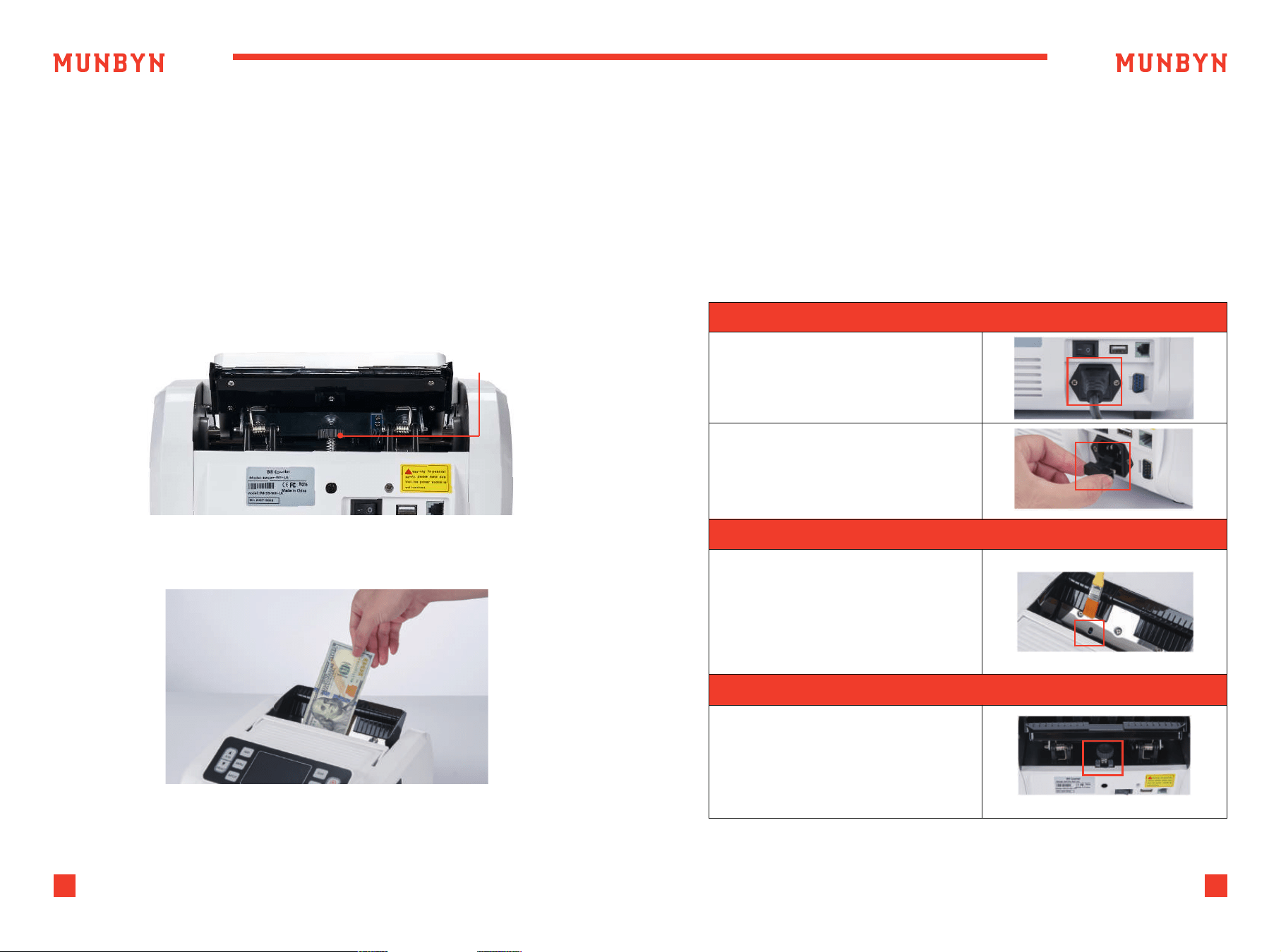
4.2. How to Place Banknotes?
Placing neatly arranged banknotes into the hopper according to the
following steps can avoid jamming or false reporting. It is recommended
to insert no more than 150 banknotes at a time.
4.3. Operating Modes
1) Adjust the width of the banknote guider to match the width of the
banknote currently being counted.
2) Place the banknote following the steps below, allowing it to slide
naturally into the Hopper.
1
2 3
4
5
Figure 4-2 Banknote Placement Steps
Figure 4-3 AUTO Mode
4.3.1. Auto/Manual Mode
IMC09 is set to automatically count notes by default. Press "A/W" button
to switch to manual counting.
In Auto mode, the IMC09 starts count automatically as soon as the bills
placed in the hopper.
In Manual mode, the IMC09 will not start counting automatically; you
must press the “START” button to begin each count.
4.3.2. Counting Mode(CNT)
As shown in the figure 4-4, IMC09 has no anti-counterfeiting function in
CNT mode, and only calculates the number of banknotes.
Placing additional bills in the hopper:
Please be sure the stacker does not accumulate more bills than it can
hold (150 PCS), as this will cause jamming, and may lead to a motor failure.
Figure 4-4 CNT Mode
9
Support: +1 650 206 2250
10
Support: +1 650 206 2250
Figure 4-5 SDC Mode
Figure 4-7 Batch Number Setting
Figure 4-6 MDC Mode
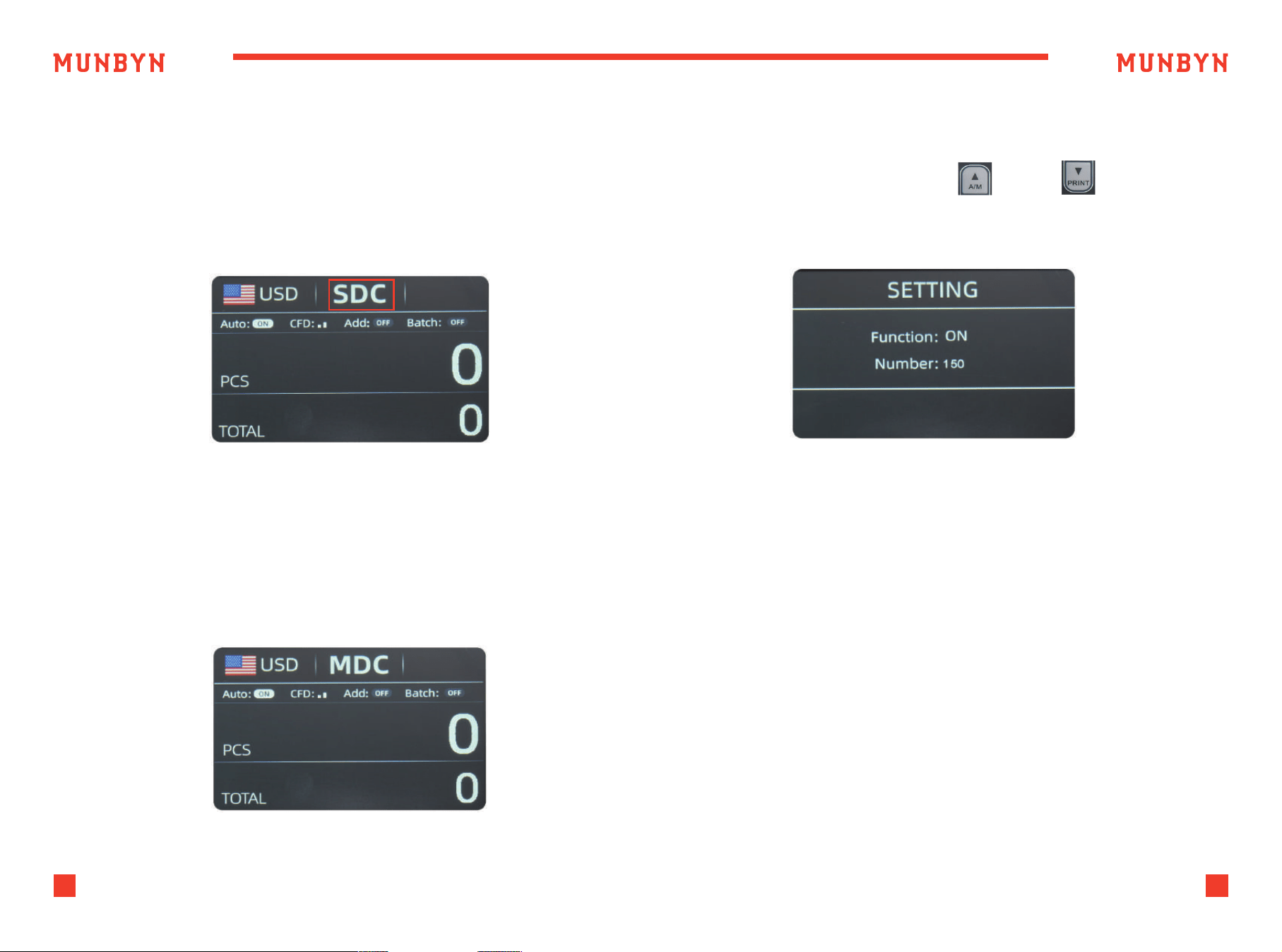
4.3.3. Sorting Mode(SDC)
4.3.4. Mix Mode(MDC)
As shown in Figure 4-5, the IMC09 is in SDC mode. In this mode,
the IMC09 will count banknotes of the same denomination as the
selected currency. The first banknote counted will serve as a reference,
and the device will also save detailed information about the counted
banknotes. This information includes the total amount and the total
number of banknotes in the stacker, which allows users to easily verify
the count.
4.3.5. Batch Mode
Press the "BATCH" button to sequentially change the BATCH number:
0-20-50-100-150, or press the "A/M" / "PRINT" button to
increase or decrease the BATCH number.
4.3.6. ADD Mode
After turning on the ADD mode, the number and amount of banknotes
counted will accumulate continuously. Pressing the ESC button can clear
the current data to record new counting data.
The machine will start counting automatically once bills are placed in
the hopper. As soon as the machine counts the desired batch quantity,
it will stop. The screen will show the number of bills in the stacker.
When the stacker is emptied, the machine will automatically start
counting the next preset batch quantity.
As shown in Figure 4-6, the IMC09 is in MDC mode. In this mode, the
IMC09 will count all denominations of the selected currency's banknotes,
while simultaneously saving the detailed information of the counted
banknotes. This information includes the total amount and the total
number of banknotes in the stacker, making it convenient for users to
review.
11
Support: +1 650 206 2250
12
Support: +1 650 206 2250
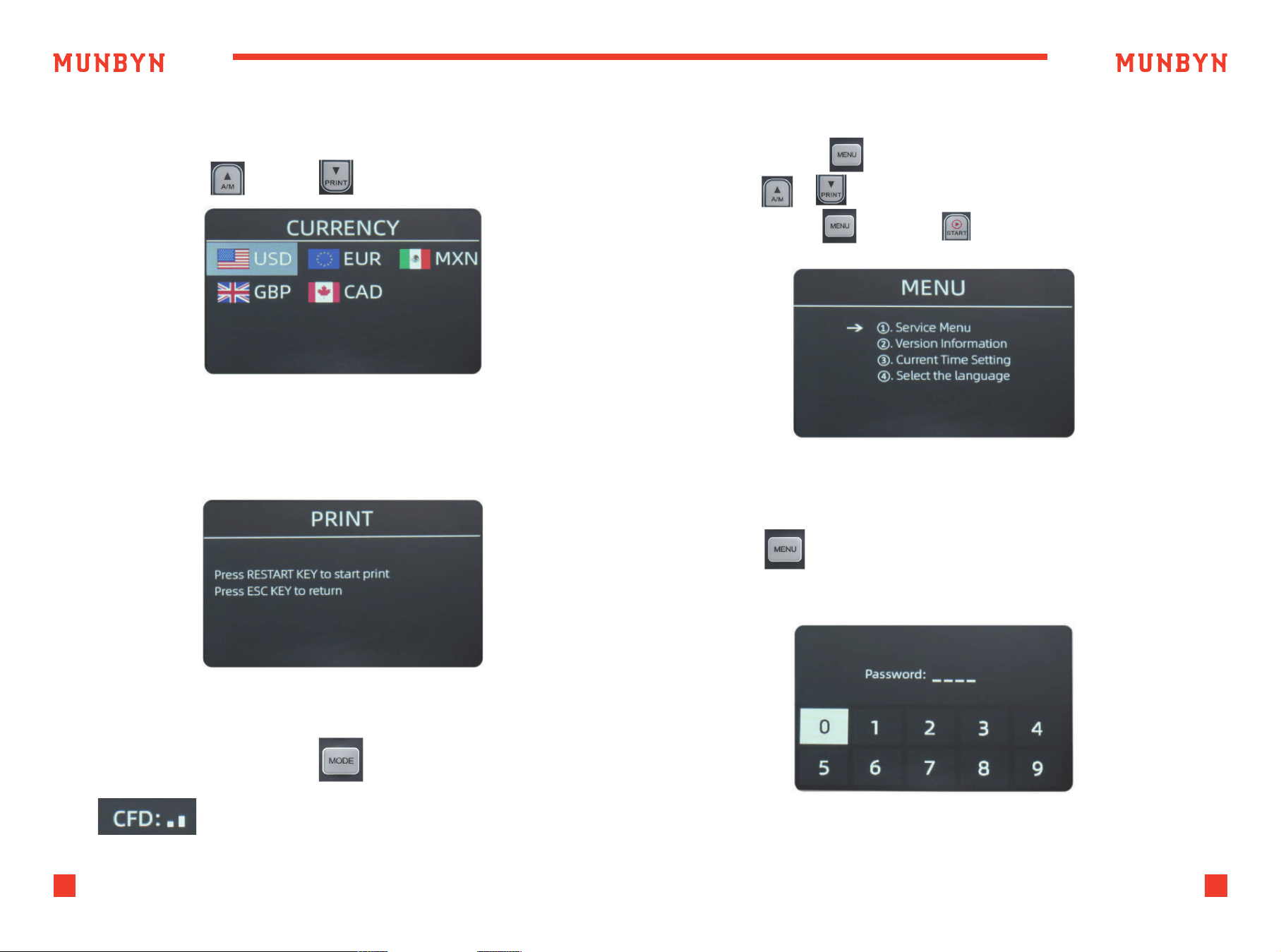
4.3.7. Currency Mode Selection
Press “CUR” button to enter Currency interface,
press the "A/M" / "PRINT" to select currency.
4.3.8. Print Data
After connecting the printer, press PRINT button to print the information
about counting data.
4.3.9. Authentication level
Long press the MODE button to adjust the sensitivity of
counterfeit detection.
Press the “MENU” to enter the user menu interface.
Use the & button to select an option,
press the “MENU” or “START” key to confirm the selection.
5.0. Settings
5.1. Service Menu
Press the key to enter service menu, you will be requested to input a
password with the following interface. The default password is 9999.
Figure 5-1 Menu Interface
Figure 4-8 Currency Setting
Figure 4-9 Print Setting
Figure 5-2 Password Interface
After input the password, the interface showed in Figure 5-3 will be
displayed.
Use the cursor to select with sub-menu you want to enter, and press
MENU button to confirm, and press ESC button to quit.
13
Support: +1 650 206 2250
14
Support: +1 650 206 2250
Figure 5-2 Password Interface
Figure 5-3 Sensor Values
Figure 5-5 IR Calibration Steps
Figure 5-6 MG/MT Waveforms
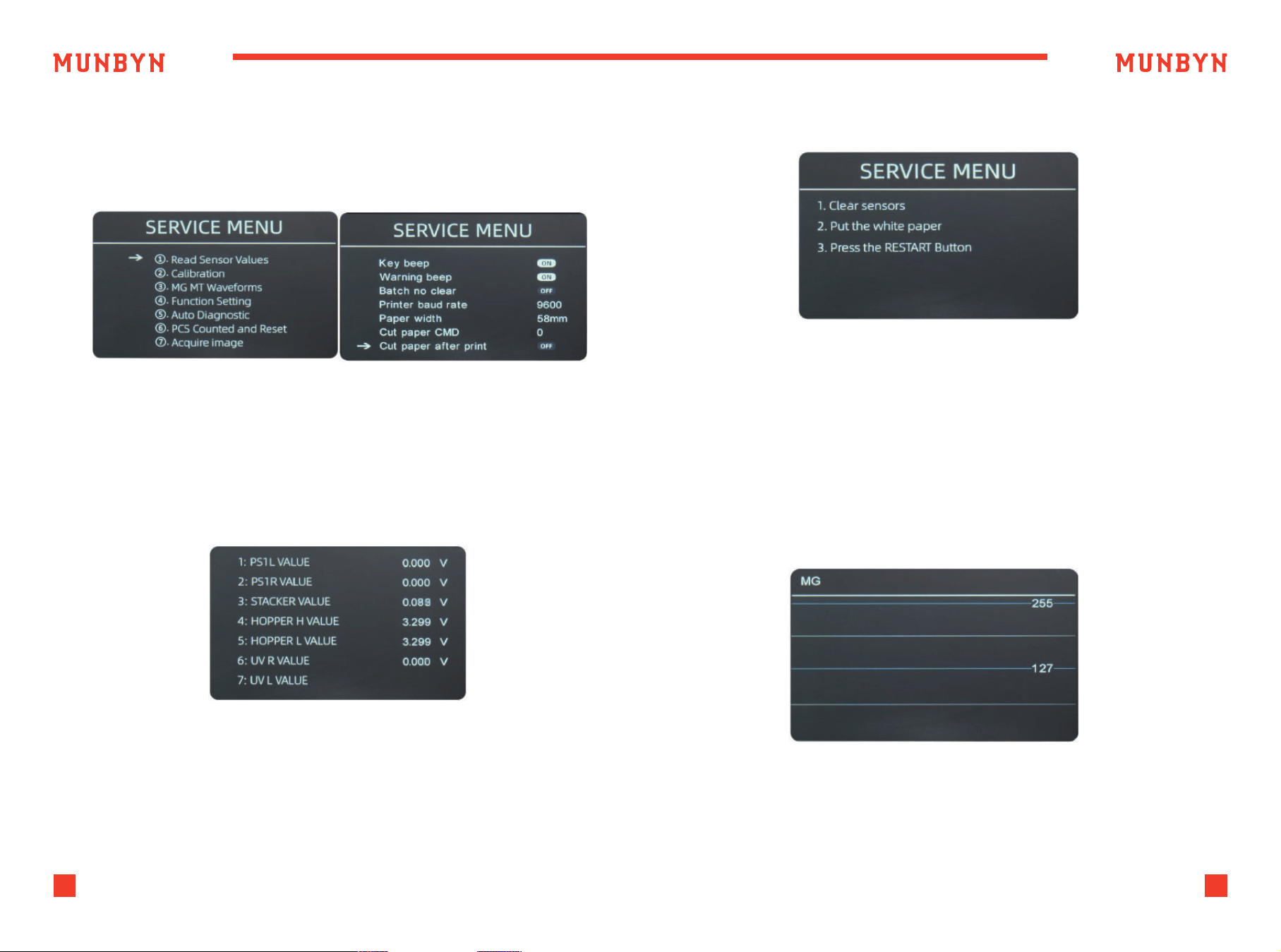
5.1.1. Read Sensor Values
As shown in Figure 5-4, the sensors values are only for engineer to check
whether any sensor has a malfunction. If you meet any problem about
use, please take a photo of this page and contact us.
5.1.2. IR Calibration
5.1.3. MG/MT Waveforms
If you meet cases about banknote detection errors, please try to calibrate
the CIS. The CIS calibration steps are shown in Figure 5-5. For more detail
instruction, we recommend you to see the reference manual or watch
the video: http://u.pc.cd/qRsctalK
15
Support: +1 650 206 2250
16
Support: +1 650 206 2250
5.1.4. Function Setting
5.1.4.1 KEY BEEP
To enter the Function Setting interface by press the key, as shown in
the following figure.
Use the cursor to select with sub-menu you want to turn on/off, and press
MENU button to confirm, and press ESC button to quit.
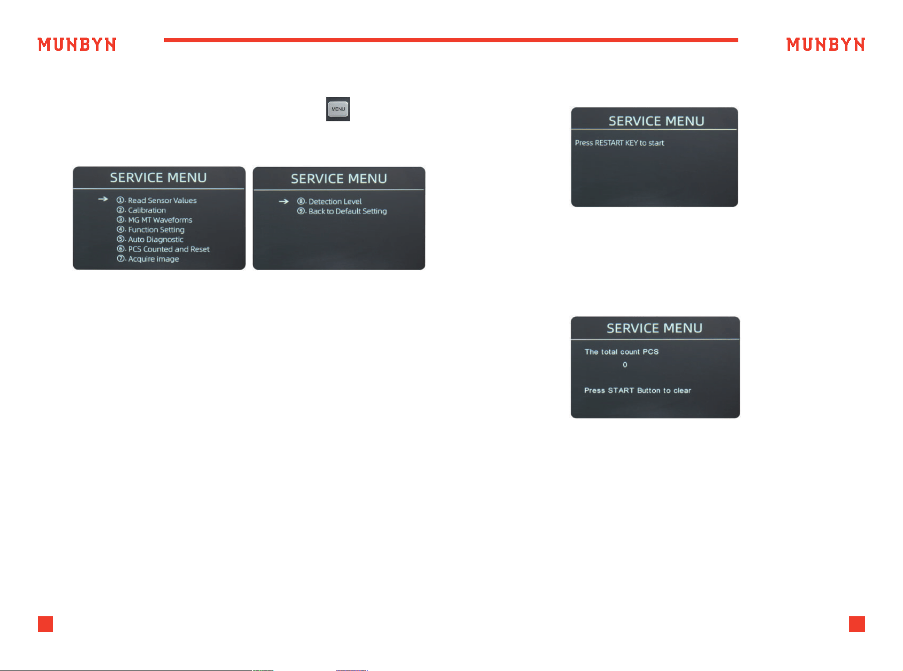
5.1.5. Auto Diagnostic
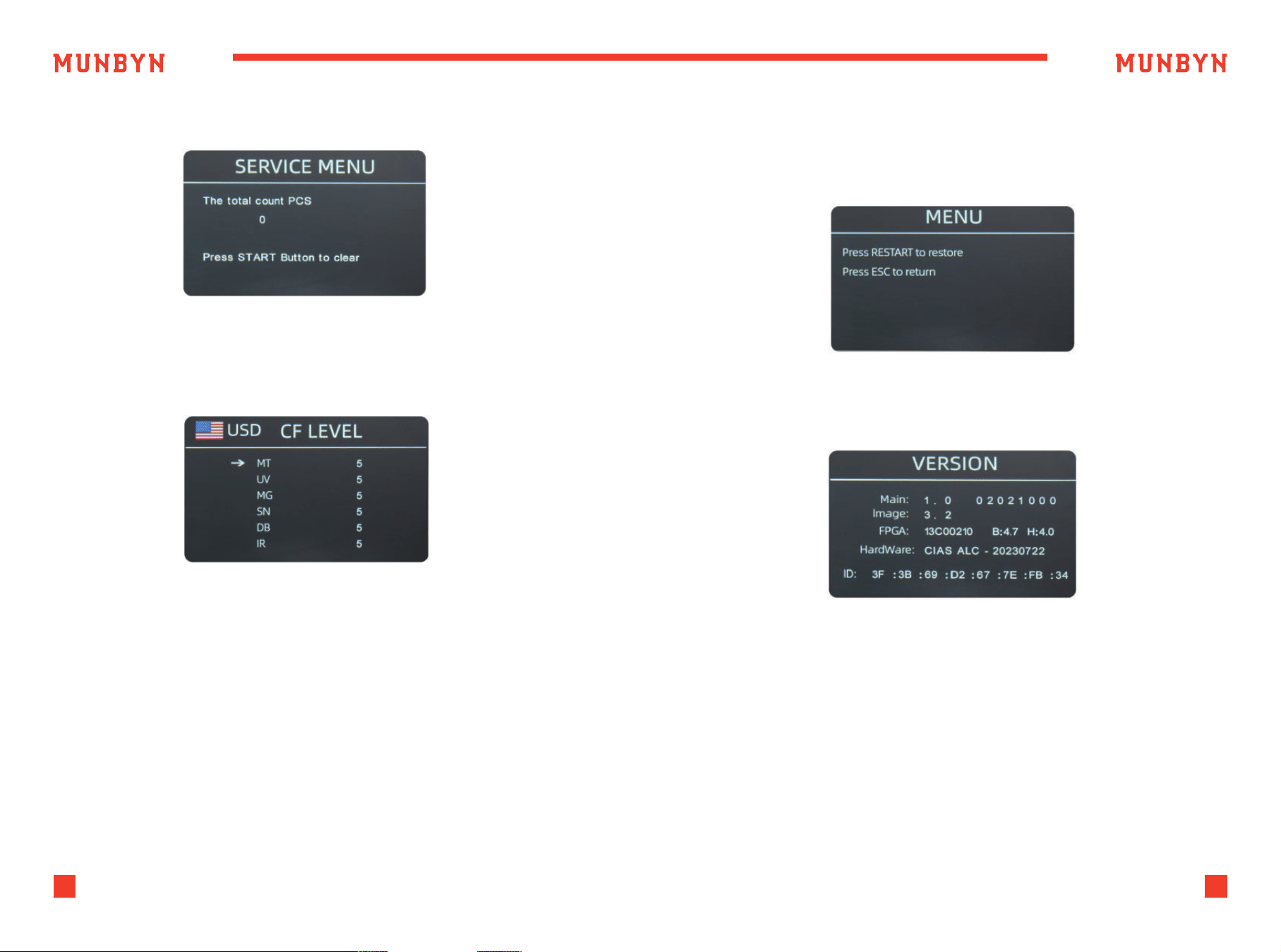
5.1.6. PCS Counted and Reset
This is for production and professional servicing purpose.
Move the cursor to the KEY BEEP option, press the MENU button to
turn on or off the key beep.
5.1.4.2 WARNING BEEP
Move the cursor to the WARNING BEEP option, press the MENU button
to turn on or off the warnning beep.
5.1.4.3 BATCH NO CLEAR
After turning on this setting, the data of the previous batch will not be
clear, and will be accumulated to the next batch.
5.1.4.4 PRINTER BAUD RATE
Switch the baud rate of the IMC09 serial port to 9600 or 115200.
Figure 5-7 MG/MT Waveforms
Figure 5-8 Auto Diagnostic
This is to tell you the total quantity of counted bills in this counter since
last time clearing to zero.
Figure 5-9 PCS Counted and Reset
17
Support: +1 650 206 2250
18
Support: +1 650 206 2250
5.1.7. Acquire CIS image 5.1.9. Back to Default setting
5.1.8. Detection Level
This is for servicing purpose.
As shown in Figure 5-13, press the menu key to reset all of the settings you
changed before.
You are available to check the version information.
As shown in Figure 5-11, you can use the left and right direction key to
select, and up and down direction key to change the sensitivity levels.
The currency code in the right part is indicating for which currency you
are operating.
Note:
Please do not change without communicating with us.
Figure 5-10 Acquire CIS Image
Figure 5-13 Back to the Default Setting
Figure 5-14 Version Information
Figure 5-11 CF Level
5.2. Version Information
19
Support: +1 650 206 2250
20
Support: +1 650 206 2250
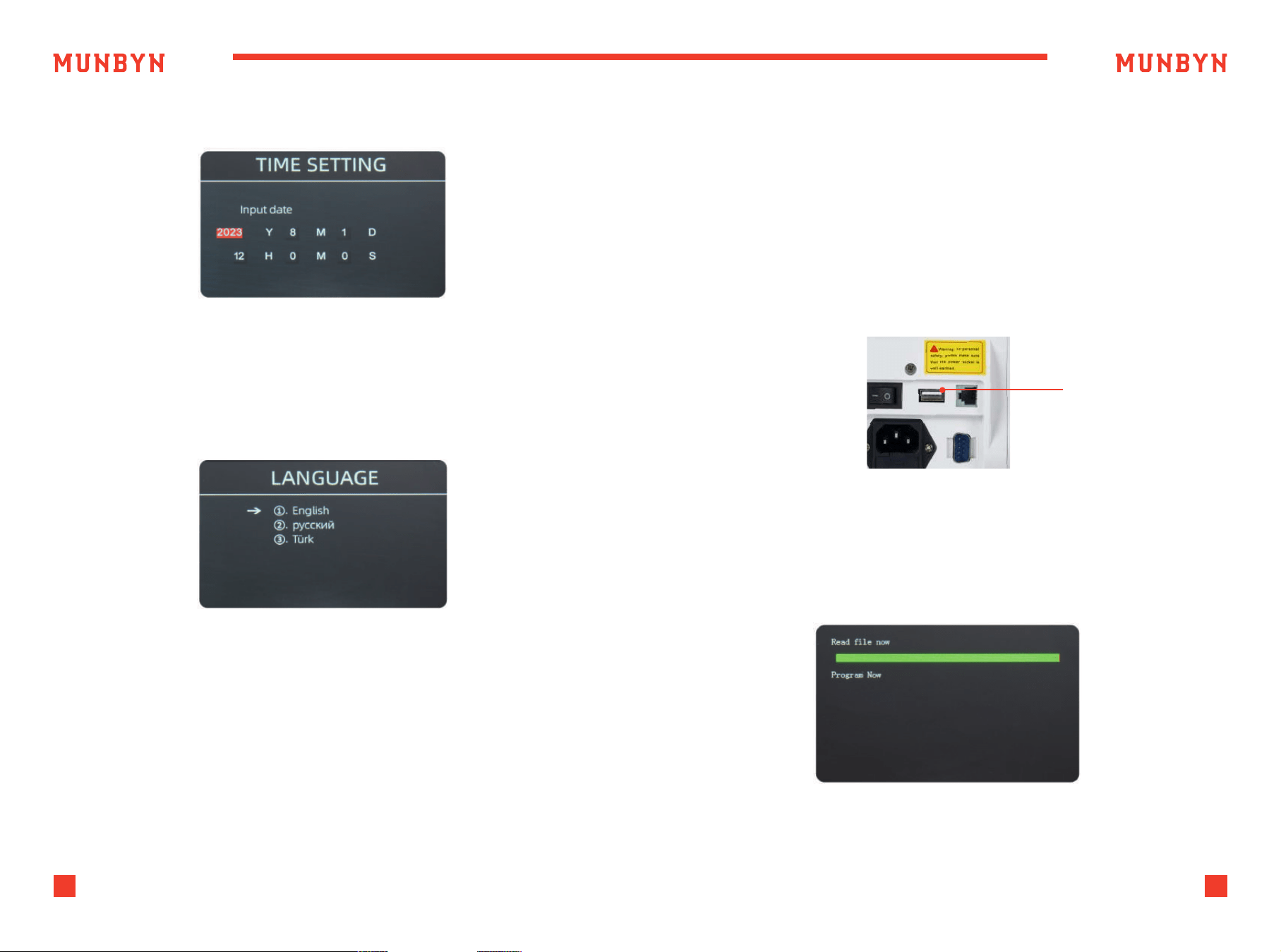
As shown in Figure 5-15, you can set the date or time according to your
preference.
Figure 5-15 Time Setting
Figure 5-16 Language Selection
Figure 6-1 USB Upgrade Port
Figure 6-2 Upgrade File Reading
5.3. Time Setting
U-disk upgrade method is adopted for the software upgrade of this
product. Please upgrade the software according to the following steps.
1 ) The upgrade file needs to be moved to the root directory of the U-disk.
(please do not change the file name or format of the upgrade file,
and there cannot be two or more upgrade files in the root directory
of the U-disk).
2 ) Insert the USB disk into the USB interface at the rear of the machine.
Make sure the power is off before insert the U-disk.
USB Upgrade Port
3 ) Turn on the counter, and the machine will automatically recognize
the upgrade file. Upon successful recognition, the machine will read
the file first.
You are available to set the language you want.
5.4. Language Selection
6.0. Software Upgrade
21
Support: +1 650 206 2250
22
Support: +1 650 206 2250
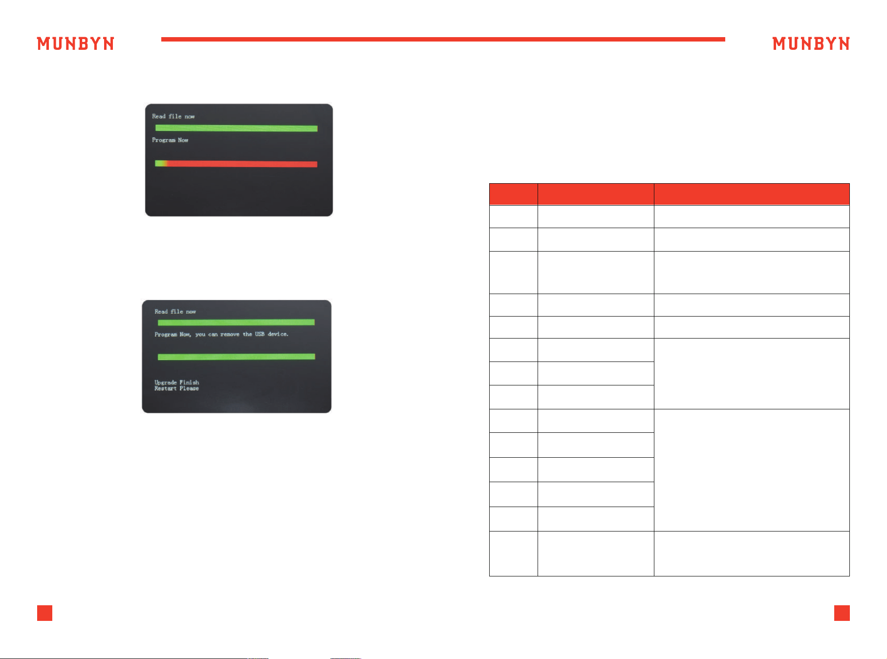
Figure 6-3 Program the Upgrade File
Figure 6-4 Program Finish
4 ) And program the file to the counter.
5 ) After finish the programming, unplug the USB disk and turn off the
machine.
The description of the error codes and the related handling methods are
shown in table 7-1.
Table 7-1 Error Code
El Bill UV sensor error Remove the banknote, clean the UV sensor
E2 Bill double error If the errors occur frequently, adjust the
E3/E8
E4
Chain notes error
Half notes error
If the errors occur frequently, adjust the
screw toward the anti-clockwise to
decrease the feeding gap.
Remove the banknote
ElO Image Error Clean the IR sensor, and calibrate the IR
Ell/El2 Denomination Error
El3 Face Recognition Error
El4 Size Recognition Error
Remove the banknote,clean the IR sensor;
Perform the IR sensor calibration;
Collect the data of the banknote.
E20 MT Error
E2l MGl Error
E22 MG2Error
E23 MG3 Error
E24 MG4error
Remove the banknote, clean or replace
the MG sensors
E30-E61 IR Error
Remove the banknote,clean the IR sensor;
Perform the IR calibration;
Collect data of the banknote.
Code Error Description Handling Method (Recommendation)
6 ) Turn on the machine to enter the main interface. Software upgrade
has been finished.
7.0. Maintenance and Troubleshooting
7.1. Error Code and Solution
23
Support: +1 650 206 2250
24
Support: +1 650 206 2250
Generally speaking, most of the above errors be caused by dust or dirt
inside of the machine, so keeping the machine clean is highly
recommended.
When banknote feeding is unsmooth or banknote counting is inaccurate,
it can be solved through adjusting the vertical adjusting screw as well
as the gap between resistance rubber and rubber wheel. Then you can
put in a banknote and hold, if you feel the pull, the machine is workable.
Turn it clockwise to decrease gap in order to add friction (tight).
Turn it anticlockwise to increase gap in order to reduce friction (loose).
7.2. Hopper Plate Adjustment
Before repair, please check the problems as below.
NOTE:
Before troubleshooting, please turn off the power switch and unplug
the outlet.
7.3. Common Trouble and Solution
Figure 7-2 Adjustable Screw
Figure 7-3 Feeding Gap Adjustment with One Banknote
Adjustable Screw
Table 7-4 Common Trouble and Solution
Check if the plug is well inserted
into socket
Check if the power fails or fuse
burn out
Feeding Sensor covered in dust?
Clean
Hopper position adjusted improperly?
Not working
Fail to start or stop normally
Counting Error

25
Support: +1 650 206 2250
26
Support: +1 650 206 2250
Scan the QR code for
Facebook online chat
Email:
(24-7 online support)
Website:
www.munbyn.com
(how-to videos, warranty details)
WhatsAPP:
+86 18144898200
MUNBYN provides 18 months warranty and lifetime free service.
If you encounter any issues with the product, please contact the
MUNBYN team to promptly receive troubleshooting tips or a replacement.
FCC Caution:
This device complies with part 15 of the FCC Rules. Operation is
subject to the fo llowing two conditions: (1) This device may not cause harmful
interference, and (2) this device must accept any interference received,
including interference that may cause undesired operation. Any Changes or
modifications not expressly approved by the party responsible for compliance
could void the user's authority to operate the equipment.
Note: This equipment has been tested and found to comply with the limits for
a Class B digital device , pursuant to part 15 of the FCC Rules. These limits are
designed to provide reasonable protec tion against harmful interference in a
residential installation. This equipment generates uses and can radiate radio
frequency energy and, if not installed and used in accordance with the
instruct ions, may cause harmful interference to radio communications.
However, there is no guarantee that interference will not occur in a particular
installation. If this equipment does cause harmful interference to radio or
television reception, which can be determined by turning the equipment
off and on, the user is encouraged to try to correct the interference by one or
more of the fo llowing measures: -Reorient or relocate the receiving antenna.
-Increase the separation between the equipment and receiver.-Connect the
equipment into an outlet on a circuit different from that to which thereceiver
is connected.-Consult the dealer or an experienced radio/TV technician
for help.
Contact us