
Business Networking Solution
Installation Guide
Easy Managed Switch

About this Installation Guide
This Installation Guide describes the hardware characteristics, installation methods and the
points that should be attended to during the installation. This Installation Guide is structured as
follows:
Chapter 1 Introduction
This chapter describes the external components of the switch.
Chapter 2 Installation
This chapter illustrates how to install the switch.
Chapter 3 Connection
This chapter illustrates how to do the physical connection of the switch.
Chapter 4 Configuration
This chapter illustrates how to configure the switch.
Appendix A Troubleshooting
Appendix B Specifications
Audience
This Installation Guide is for:
Network Engineer Network Administrator
Conventions
• Some models featured in this guide may be unavailable in your country or region. For local sales
information, visit https://www.tp-link.com.
• The figures in Chapter 2, Chapter 3 and Chapter 4 are for demonstration purposes only. Your
switch may differ in appearance from that depicted.
• PoE budget calculations are based on laboratory testing. Actual PoE power budget is not
guaranteed and will vary as a result of client limitations and environmental factors.
• This guide uses the specific formats to highlight special messages. The following table lists the
notice icons that are used throughout this guide.
Remind to be careful. A caution indicates a potential which may result in device damage.
Remind to take notice. The note contains the helpful information for a better use of the
product.
Related Document
The User Guide of the product are provided on Download Center. To obtain the latest product
information, visit the official website: https://www.tp-link.com/support/download/.

Contents
Chapter 1 Introduction ——————————— 01
1.1 Product Overview ...........................................................01
1.2 Appearance .......................................................................01
Chapter 2 Installation ——————————— 05
2.1 Package Contents ..........................................................05
2.2 Safety Precautions .........................................................05
2.3 Installation Tools ..............................................................07
2.4 Product Installation ........................................................07
Chapter 3 Connection ——————————— 09
3.1 Ethernet Port ....................................................................09
3.2 SFP Slot ..............................................................................09
3.3 Verify Installation .............................................................09
3.4 Power On ............................................................................10
3.5 Initialization ........................................................................10
Chapter 4 Conguration —————————— 11
4.1 Conguration Overview ................................................11
4.2 Standalone Mode ............................................................11
4.3 Controller Mode ...............................................................11
Appendix A Troubleshooting ———————— 12
Appendix B Specications ————————— 13
Easy Managed Switch
01 Introduction
Chapter 1 Introduction
1.1 Product Overview
Designed for small office and small business scenarios, TP-Link Easy Managed Switch provides wire-
speed performance and abundant L2 management features. It provides a variety of service features
and multiple powerful functions with high security.
The EIA-standardized framework and smart configuration capacity can provide flexible solutions for
a variable scale of networks. QoS and IGMP snooping/filtering optimize voice and video application.
Link aggregation increases aggregated bandwidth, optimizing the transport of business critical
data. WEB offers abundant management policies. TP-Link Easy Managed Switch integrates multiple
functions with excellent performance, and is friendly to manage, which can fully meet the need of the
users demanding higher networking performance.
1.2 Appearance
■
Front Panel
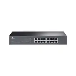
The front panel of TL-SG216E is shown as the following figure.
Figure 1-1 Front Panel of TL-SG216E
LEDs
Reset
10/100/1000 Mbps
RJ45 Ports
LEDs
LED Indication
Power
On: The switch is powered on.
Off: The switch is powered off or power supply is abnormal.
Link/Act
On: A device is linked to the corresponding port and running properly.
Flashing: Transmitting or receiving data.
Off: No device is linked to the corresponding port.
1000Mbps
On: Running at 1000 Mbps.
Off: Running at 10/100 Mbps or no device is linked to the corresponding port.
Easy Managed Switch
02Introduction
The front panel of TL-SG220PE is shown as the following figure.
Figure 1-2 Front Panel of TL-SG220PE
LED Reset Button
10/100/1000 Mbps
RJ45 Port
SFP Slot
The front panel of TL-SG228PE is shown as the following figure.
Figure 1-3 Front Panel of TL-SG228PE
LED
LED Mode
Switch Button
Reset Button
10/100/1000 Mbps
RJ45 Port
SFP Slot
LEDs
LED Indication
PWR
On: The switch is powered on.
Off: The switch is powered off or power supply is abnormal.
SYS
Flashing: The switch works properly.
On or Off: The switch works improperly.
PoE Max
On: The remaining PoE power is ≤ 7 W.
Flashing: The remaining PoE power keeps ≤ 7 W after this LED is on for 2 minutes.
Off: The remaining PoE power is > 7 W.
FAN
(Only for TL-SG228PE)
Green: All the fans work properly.
Yellow: Not all the fans work properly.
Speed
Green On: Running at 1000 Mbps, but no activity.
Green Flashing: Running at 1000 Mbps and transmitting or receiving data.
Yellow On: Running at 10/100 Mbps, but no activity.
Yellow Flashing: Running at 10/100 Mbps and transmitting or receiving data.
Off: No device is linked to the corresponding port.
PoE
(Only for TL-SG220PE)
Green On: The port is supplying power normally.
Green Flashing: The supply power exceeds the correponding port's maximum
power.
Yellow On: Overload or short circuit is detected.
Off: Not providing PoE power on the port.
Speed or PoE
(When the Speed LED is
on. Only for TL-SG228PE)
Green On: Running at 1000 Mbps, but no activity.
Green Flashing: Running at 1000 Mbps and transmitting or receiving data.
Yellow On: Running at 10/100 Mbps, but no activity.
Yellow Flashing: Running at 10/100 Mbps and transmitting or receiving data.
Off: No device is linked to the corresponding port.
Easy Managed Switch
03 Introduction
Speed or PoE
(When the PoE LED is on.
Only for TL-SG228PE)
Green On: The port is supplying power normally.
Green Flashing: The supply power exceeds the correponding port's maximum
power.
Yellow On: Overload or short circuit is detected.
Off: Not providing PoE power on the port.
SFP
Green On: Running at 1000 Mbps, but no activity.
Green Flashing: Running at 1000 Mbps and transmitting or receiving data.
Off: No device is linked to the corresponding port.
Note: SFP for port 19–20 of TL-SG220PE and port 27–28 of TL-SG228PE.
LED Mode Switch Button
Press this button to switch the LED status indication between Speed and PoE.
Reset
With the switch powered on, press Reset button for 5 seconds to reset the switch to its factory default
settings.
10/100/1000 Mbps RJ45 Port
Designed to connect to the device with a bandwidth of 10 Mbps, 100 Mbps or 1000 Mbps.
SFP Slot
Designed to install the SFP module.
Port Feature
Model 10/100/1000 Mbps RJ45 Port SFP Slot
TL-SG216E 16 /
TL-SG220PE 18 2
TL-SG228PE 26 2
■
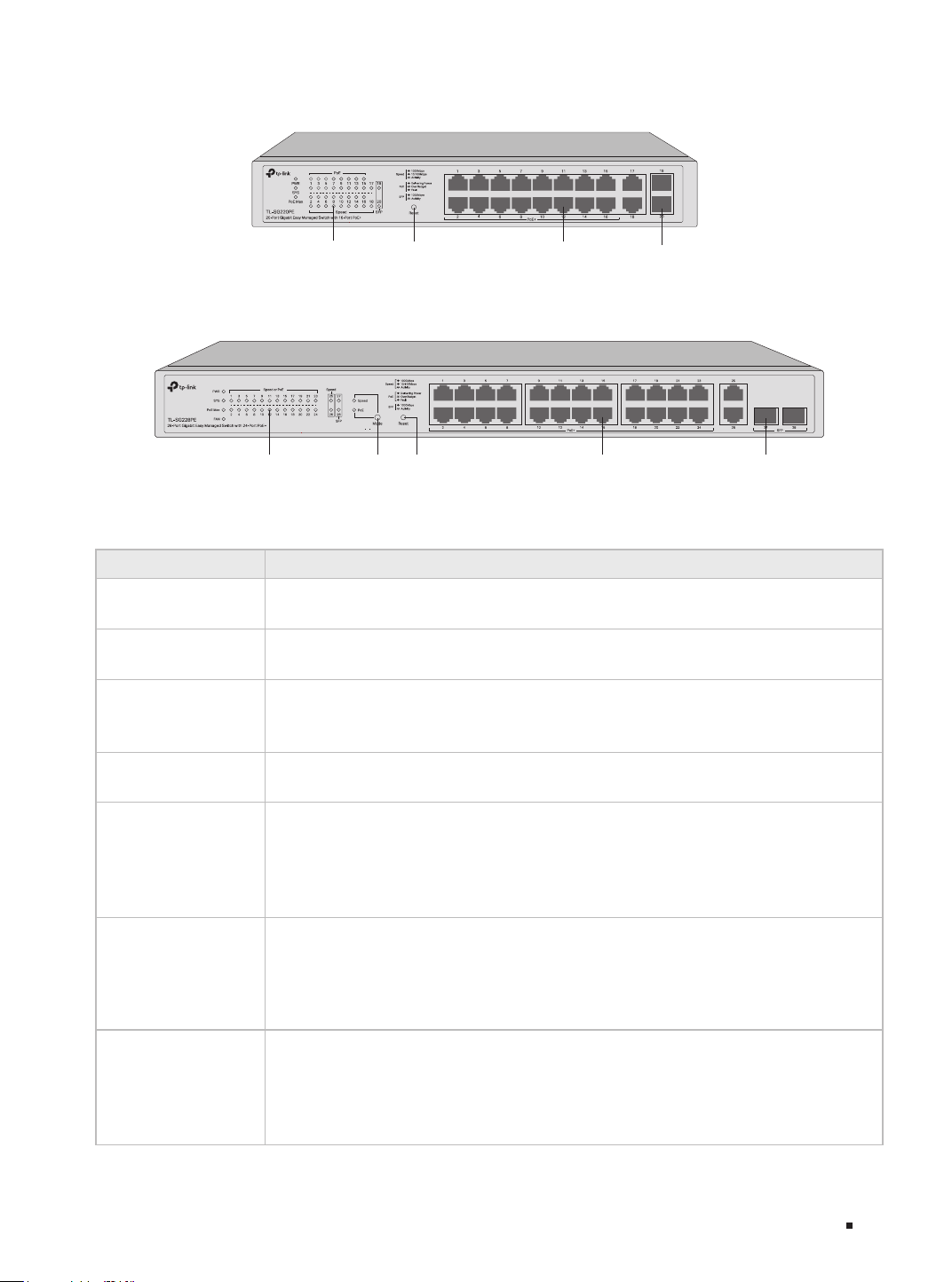
Rear Panel
The rear panel is shown as the following figure. The actual product may differ from the figure.
Figure 1-4 Rear Panel
Power Socket
Grounding Terminal
Kensington Security slot
Kensington Security Slot
Secure the lock (not provided) into the security slot to prevent the device from being stolen.
Grounding Terminal
The switch already comes with lightning protection mechanism. You can also ground the switch through
the PE (Protecting Earth) cable of AC cord or with Ground Cable. For detailed lightning protection
measures, refer to the Lightning Protection Guide: https://www.tp-link.com/us/conguration-guides/
lightning_protection_guide/.

Easy Managed Switch
04Introduction
Power Socket
Connect the female connector of the power cord here, and the male connector to the AC power outlet.
Make sure that the voltage of the power supply meets the requirement of the input voltage (100–240 V~
50/60 Hz).
Caution:
You should use the provided power cord.
Easy Managed Switch
05 Installation
Chapter 2 Installation
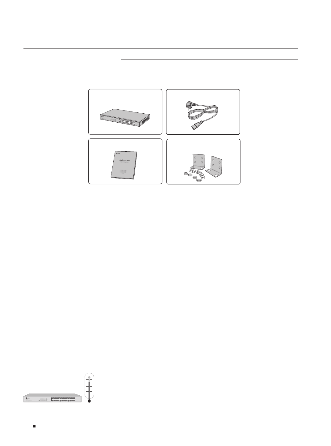
2.1 Package Contents
Make sure that the package contains the following items. If any of the listed items is damaged or
missing, please contact your distributor.
One Switch
Installation Guide
Installation Guide
Business Networking Solution
Mounting Brackets, Screws
and Feet
One Power Cord
*Images are for demonstration only. The actual items may differ in appearance and quantity from the depicted.
2.2 Safety Precautions
To avoid any device damage and bodily injury caused by improper use, you should observe the
following rules.
■
Safety Precautions
■
Keep the power off during the installation.
■
Wear an ESD-preventive wrist strap, and make sure that the wrist strap has a good skin contact and is
well grounded.
■
Use only the power cord provided with the switch.
■
Make sure that the supply voltage matches the specifications indicated on the rear panel of the
switch.
■
Ensure that the switch is installed in a well-ventilated environment and its ventilation hole is not
blocked.
■
Do not open or remove the cover of the switch.
■
Before cleaning the device, cut off the power supply. Do not clean it by the waterish cloth, and never
use any other liquid cleaning method.
■
Place the device with its bottom surface downward.
■
Site Requirements
Temperature/Humidity
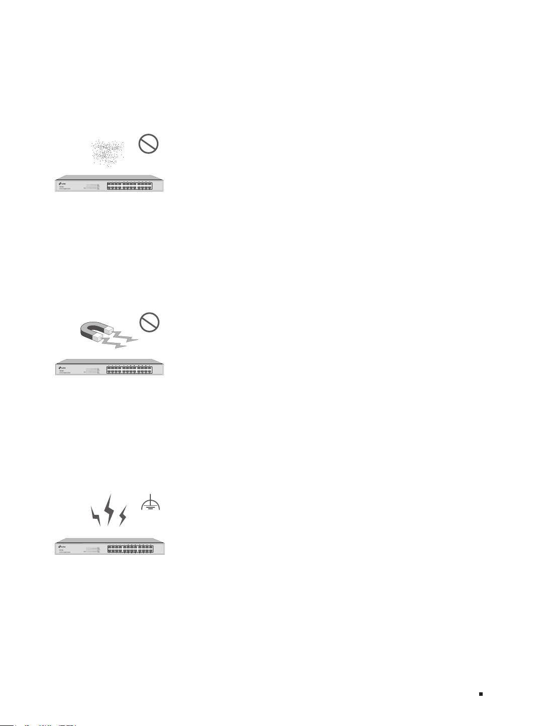
Easy Managed Switch
06Installation
Keep the equipment room at an appropriate level of temperature and humidity. Too much or too
little humidity may lead to bad insulation, leakage of electricity, mechanical property changes,
and corrosion. High temperatures may accelerate aging of the insulation materials, significantly
shortening the service life of the device. To find out the best temperature and humidity conditions
for the device, check the Appendix B Specifications.
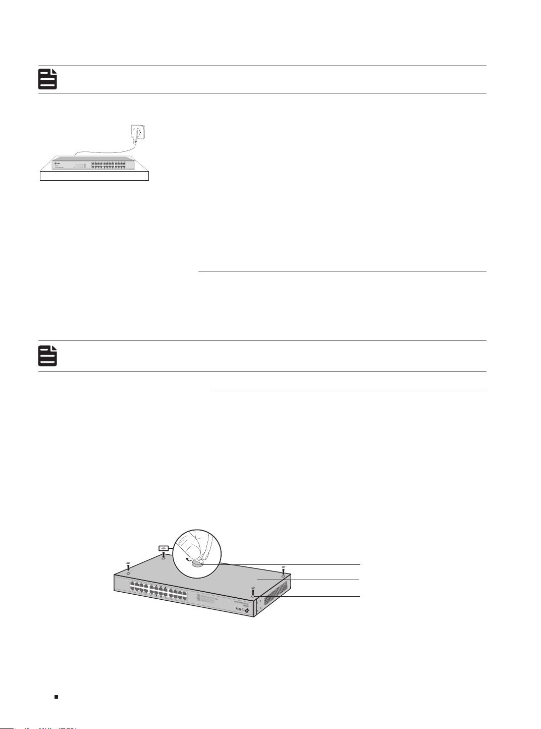
Clearness
The dust accumulated on the switch can be absorbed by static electricity and result in poor contact
of metal contact points. Some measures have been taken for the device to prevent static electricity,
but too strong static electricity can cause deadly damage to the electronic elements on the internal
circuit board. To avoid the effect of static electricity on the operation of the switch, attach much
importance to the following items:
■
Dust the device regularly, and keep the indoor air clean.
■
Keep the device well grounded and ensure that the static electricity has been transferred.
Electromagnetic Interference
Electronic elements including capacitance and inductance on the device can be affected by external
interferences, such as conducted emission by capacitance coupling, inductance coupling, and
impedance coupling. To decrease the interferences, make sure to take the following measures:
■
Use the power supply that can effectively filter interference from the power grid.
■
Keep the device far from high-frequency and strong-current devices such as radio transmitting
station.
■
Use electromagnetic shielding when necessary.
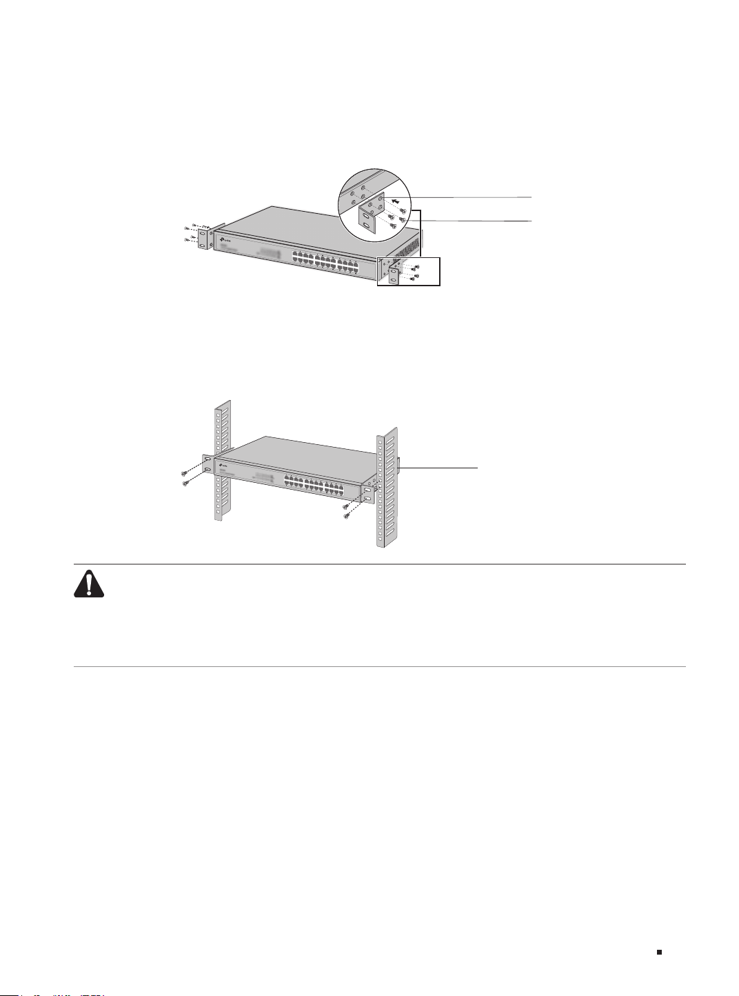
Lightning Protection
Extremely high voltage currents can be produced instantly when lightning occurs and the air in the
electric discharge path can be instantly heated up to 20,000
°C
. As this instant current is strong
enough to damage electronic devices, more effective lightning protection measures should be
taken.
■
Ensure that the rack and the device are well earthed.
■
Make sure the power socket has a good contact with the ground.
■
Keep a reasonable cabling system and avoid induced lightning.
Easy Managed Switch
07 Installation
■
Use the signal SPD (Surge Protective Device) when wiring outdoor.
Note: For detailed lightning protection measures, refer to the Lightning Protection Guide:
https://www.tp-link.com/us/conguration-guides/lightning_protection_guide/.
Installation Site
When installing the device on a rack or a flat workbench, attach much importance to the following
items:
■
The rack or workbench is flat, stable, and sturdy enough to support the weight of 5.5 kg at least.
■
The rack or workbench has a good ventilation system. The equipment room is well ventilated.
■
The rack is well grounded. Keep the device less than 1.5 meters away from the power socket.
2.3 Installation Tools
■
Phillips screwdriver
■
ESD-preventive wrist wrap
■
Cables
Note:
These tools are not included with our product. If needed, you can purchase them separately.
2.4 Product Installation
■
Desktop Installation
To install the device on the desktop, follow the steps:
1. Set the device on a flat surface which is strong enough to support the entire weight of the device
with all fittings.
2. Remove the adhesive backing papers from the feet.
3. Attach the feet to the bottom of the device to prevent it from slipping when placed on a desktop.
Figure 2-1 Desktop Installation
Feet
Bottom of the Device
Notch
■
Rack Installation
To install the device in an EIA standard-sized, 19-inch rack, follow the instructions described below:
Easy Managed Switch
08Installation
1. Check the efficiency of the grounding system and the stability of the rack.
2. Secure the supplied rack-mounting brackets to each side of the device with supplied screws, as
illustrated in the following figure.
Figure 2-2 Bracket Installation
Rack-mounting Bracket
Screw
*This image is for demonstration only
3. After the brackets are attached to the device, use suitable screws (not provided) to secure the
brackets to the rack, as illustrated in the following figure.
Figure 2-3 Rack Installation
Rack
Caution:
■
Leave 5 to 10 cm gaps around the devices for air circulation.
■
Avoid placing heavy things on the device.
■
Place the device with its bottom facing downwards.
■
Mount devices in sequence from the bottom to top of the rack and ensure a certain clearance
between devices for the purpose of heat dissipation.

Easy Managed Switch
09 Connection
Chapter 3 Connection
3.1 Ethernet Port
Connect an Ethernet port of the switch to the computer by RJ45 cable as the following figure shows.
Figure 3-1 Connecting the RJ45 Port
RJ45 Port
RJ45 Cable
3.2 SFP Slot
The following figure demonstrates the connection of SFP module to an SFP slot.
Figure 3-2 Inserting the SFP Module
SFP Slot
SFP Module
3.3 Verify Installation
After completing the installation, verify the following items:
■
There should be 5 to 10 cm of clearance around the device for ventilation and make sure the air flow
is adequate.
■
The voltage of the power supply meets the requirement of the input voltage of the device.
■
The power socket, device and rack are well grounded.
■
The device is correctly connected to other network devices.
Easy Managed Switch
10Connection
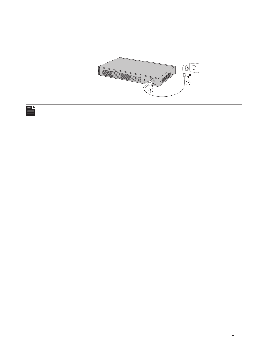
3.4 Power On
Plug the negative connector of the provided power cord into the power socket of the device and plug
the positive connector into a power outlet as the following figure shows.
Figure 3-3 Connecting to Power Supply
Note:
The gure is to illustrate the application and principle. The provided plug and the socket in your
region may dier from the gures above.
3.5 Initialization
After the device is powered on, it begins the Power-On Self-Test. A series of tests run automatically
to ensure the device functions properly. During this time, its LED indicators will respond in the
following order:
1. The Power LED indicator lights on all the time. All other LED indicators keep off.
2. After about 10 seconds, all LED indicators will turn green. Then refer to the LED statuses according
to your device model:
■
TL-SG216E: All LED indicators except the Power LED will turn off.
■
TL-SG220PE: The LED indicators of all the RJ45 ports will turn yellow momentarily, while the rest
will remain green. Subsequently, all LED indicators except the PWR LED will turn off. Then the SYS
LED indicator will flash, which represent a successful initialization.
■
TL-SG228PE: The FAN LED indicator and LED indicators of all the RJ45 ports will turn yellow
momentarily. Subsequently, all LED indicators except the PWR LED will turn off. Then the SYS LED
indicator will flash, and the FAN and Mode-Speed LED indicators will turn on, which represent a
successful initialization.
Easy Managed Switch
11 Conguration
Chapter 4 Configuration
4.1 Conguration Overview
The switch supports two configuration options:
■
Standalone Mode: Configure and manage the switch singly.
■
Controller Mode: Configure and manage the network devices centrally. It is recommended in the
large-scale network, which consists of mass devices such as access points, switches, and gateways.
Note:
The switch support both Standalone Mode and Controller Mode. When the switch is changed
from Standalone Mode to Controller Mode, you should recongure the switch.
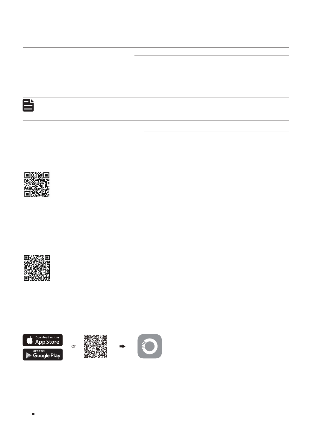
4.2 Standalone Mode
To set up a standalone switch, scan the QR code or refer to the Standalone Configuration Guide at
https://www.tp-link.com/support/faq/4097/.
Scan for Standalone Configuration Guide
4.3 Controller Mode
To set up a switch with an Omada Controller, scan the QR code or refer to the Omada Controller
configuration guide at https://www.tp-link.com/support/faq/4096/.
Scan for Controller Configuration Guide
* Omada App
With the TP-Link Omada app, you can access and manage your devices at a local site or remotely
with a tap of your phone. You can download and install the TP-Link Omada app from the App Store or
Google Play.
Scan for Omada App
Download Omada App
For detailed instructions on device configuration, refer to the user guides of the Controller and
switches. The guides can be found in the support center of our official website:
https://www.tp-link.com/support/.

Easy Managed Switch
12Appendix A Troubleshooting
Appendix A Troubleshooting
Q1. What could I do if I forgot the username and password of the switch?
Press the Reset button for at least 5 seconds to reset the system. The system will be reset to the factory
default settings, and you can set a new login username and password.
Q2. Why does the PWR/Power LED work abnormally?
The PWR/Power LED should be lit up when the power system works normally. If the PWR/Power LED
worked abnormally, try the following:
1. Make sure that the power cable is connected properly, and the power contact is normal.
2. Make sure the voltage of the power supply meets the requirement of the input voltage of the switch.
Q3. What should I do if I cannot access the web management page?
Try the following:
1. Check every port LED on the switch and make sure the Ethernet cable is connected properly.
2. Try another port on the switch and make sure the Ethernet cable is suitable and works normally.
3. Power off the switch and, after a while, power it on again.
4. Make sure the IP address of your PC is set within the subnet of the switch.
5. If you still cannot access the configuration page, please reset the switch to its factory defaults. Then
the IP address of your PC should be set as 192.168.0.x ("x" is any number from 2 to 254) and subnet
mask as 255.255.255.0.

Easy Managed Switch
13 Appendix B Specications
Appendix B Specifications
Item Content
Standards
IEEE 802.3, IEEE 802.3i, IEEE 802.3u, IEEE 802.3ab
IEEE 802.3z (For TL-SG220PE/ TL-SG228PE)
IEEE 802.3x, IEEE 802.1p, IEEE 802.1q
IEEE 802.3af, IEEE 802.3at (For TL-SG220PE/ TL-SG228PE)
Transmission
Medium
10BASE-T: 2-pair UTP/STP of Cat. 3,4,5 (maximum 100 m)
100BASE-TX: 2-pair UTP/STP of Cat. 5 or above (maximum 100 m)
1000BASE-T: 4-pair UTP/STP of Cat. 5e or above (maximum 100 m)
1000BASE-SX/LX/LX10/BX10: MMF, SMF (For TL-SG220PE/ TL-SG228PE)
LEDs
TL-SG216E: Power, Link/Act, 1000Mbps
TL-SG220PE: PWR, SYS, PoE MAX, Speed, PoE, SFP
TL-SG228PE: PWR, SYS, PoE MAX, FAN, Speed or PoE, Speed, PoE, SFP
Operating Temperature
TL-SG220PE
: -5 °C to 40 °C (23 °F to 104 °F)
TL-SG216E/ TL-SG228PE:
-5 °C to 50 °C (23 °F to 122 °F)
Storage Temperature -40 °C to 70 °C (-40 °F to 158 °F)
Operating Humidity 10% to 90%RH Non-condensing
Storage Humidity 5% to 90%RH Non-condensing

Safety Information
• Keep the device away from water, fire, humidity or hot environments.
• Do not attempt to disassemble, repair, or modify the device. If you need service, please contact us.
• Place the device with its bottom surface downward.
• The plug on the power supply cord is used as the disconnect device, the socket-outlet shall be easily accessible.
• The socket-outlet shall be installed near the equipment and shall be easily accessible.
• Plug the product into the wall outlets with earthing connection through the power supply cord.
• The PoE ports shall not be used to charge lithium batteries or devices supplied by lithium batteries.
This equipment is not suitable for use in locations
where children are likely to be present.
Please read and follow the above safety information when operating the device. We cannot guarantee that no accidents
or damage will occur due to improper use of the device. Please use this product with care and operate at your own risk.
©2025 TP-Link 7100001354 REV2.0.0
For technical support, the user guide and other information, please visit https://www.tp-link.com/support/, or simply scan the QR code.
