
BATTERY CHARGER
SAVE THIS MANUAL: KEEP THIS MANUAL FOR SAFETY WARNINGS, PRECAUTIONS, ASSEMBLY,
OPERATING, INSPECTION, MAINTENANCE AND CLEANING PROCEDURES. WRITE THE PRODUCT’S
SERIAL NUMBER ON THE BACK OF THE MANUAL NEAR THE ASSEMBLY DIAGRAM (OR MONTH
AND YEAR OF PURCHASE IF PRODUCT HAS NO NUMBER)
OWNER’S MANUAL AND SAFETY INSTRUCTIONS
ITEM: 26807
FOR QUESTIONS PLEASE CALL OUR CUSTOMER SUPPORT: 909.628.0880 MON-FRI 9AM TO 3PM PST

IMPORTANT SAFETY INFORMATION
GENERAL SAFETY WARNINGS
Read all safety warnings and instructions. Failure to follow the warnings and instructions may result
in electric shock, re and/or serious injury. Save all warnings and instructions for future reference.
1
Batteries generate explosive gases during normal operation. Use in well-ventilated area.
Consider having someone close enough or within the range of your voice to come to your aid when you
work near a battery.
DO NOT smoke, strike a match, or cause a spark in vicinity of battery or engine. Avoid explosive gas,
ames and sparks.
Remove all personal jewelry, such as rings, bracelets, necklaces, and watches while working with a
vehicle battery. These items may produce a short-circuit that could cause severe burns.
Be extra cautious to reduce risk of dropping a metal tool onto the battery. It might spark or short-circuit a
battery or other electrical hardware which may cause an explosion or re.
Wear complete eye protection, hand and clothing protection. Avoid touching eyes while working near a
battery.
Study all battery manufacturer’s specic precautions such as removing or not removing cell caps while
charging and recommended rates of charge.
Clean battery terminals before connected with the charger. Be careful to keep corrosion from coming in
contact with eyes.
When it is necessary to remove a battery from vehicle to charge, always remove grounded terminal from
battery rst. Make sure all accessories in the vehicle are off in order to prevent an arc.
It is NOT intended to supply power to an extra-low-voltage electrical system or to charge dry-cell batteries.
Charging dry-cell batteries may burst and cause injury to persons and property.
NEVER charge a frozen, damaged, leaking or non-rechargeable battery.
If battery electrolyte contacts skin or clothing, wash immediately with soap and water. If electrolyte enters
eye, immediately ood eye with running clean cold water for at least 15 minutes and get medical attention
immediately.
DO NOT place the charger in the engine compartment or near moving parts or near the battery; place as
far away from them as DC cable permits. NEVER place a charger directly above a battery being charged;
gases or uids from battery will corrode and damage charger.
DO NOT cover the charger while charging.
DO NOT expose to rain or wet conditions.
Connect and disconnect DC output only after setting AC cord from electric outlet.
Use of an attachment not recommended or sold by the manufacturer may result in a risk of re, electric
shock or injury to persons.
DO NOT overcharge batteries by selecting the wrong charge mode.
To reduce the risk of damage to electric plug and cord, pull by the plug rather than the cord when
disconnecting charger.
To reduce risk of electric shock, unplug charger from outlet before attempting any maintenance or cleaning.
Operate with caution if the charger has received direct hit of force or been dropped. Have it checked and
repaired if damaged.
Any repair must be carried out by the manufacturer or an authorized repair agent in order to avoid danger.
OPERATION
2
1) Identify polarity of battery posts. The positive battery terminal is typically marked by these letters or symbol
(POS,P,+). The negative battery terminal is typically marked by these letters or symbol (NEG,N,-).
2) Do not make any connections to the carburetor, fuel lines, or thin metal parts.
3) Identify if you have a negative or positive grounded vehicle. This can be done by identifying which battery
post (NEG or POS) is connected to the chassis.
4) For a negative grounded vehicle (most common): connect the RED POSITIVE battery clamp rst to the
positive battery terminal, then connect the BLACK NEGATIV battery clamp to the negative battery terminal or
vehicle chassis.
5) For a positive grounded vehicle (very uncommon): connect the BLACK NEGATIV battery clamp rst to the
negative battery terminal, then connect the RED POSITIVE battery clamp to the positive battery terminal or
vehicle chassis.
6) When disconnecting, disconnect in the reverse sequence, removing the negative rst (or positive rst for
positive ground systems).
NOTICE: If battery clamps are reversely connected to battery terminals, the ERROR LED will be on. Exchange
the battery clamps to solve this problem.
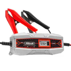
1) The Charger is perfect for keeping all of your 12V and 6V lead-acid batteries in top condition, including WET
(Flooded), GEL, MF (Maintenance-Free) and EFB (Enhanced Flooded Battery) .
2) Built-in intelligent microprocessor makes charging and maintaining faster, easier and safer.
3) This charger has safety features, including spark proof, protection for reverse polarity, short circuit,
overcurrent and overcharge.
4) It has auto-memory, which returns to last selected mode when restarted.
5) When Emerald Green LED is ashing, the charger is in bulk charge at a constant 1000mA rated current
output. When Emerald Green LED turns to solid, the battery is fully charged.
6) Since this is a battery maintainer and you will keep it connected with vehicle battery for a long time, do
monitor monthly. Follow the battery manufacturer’s instructions for adding distilled water if applicable.
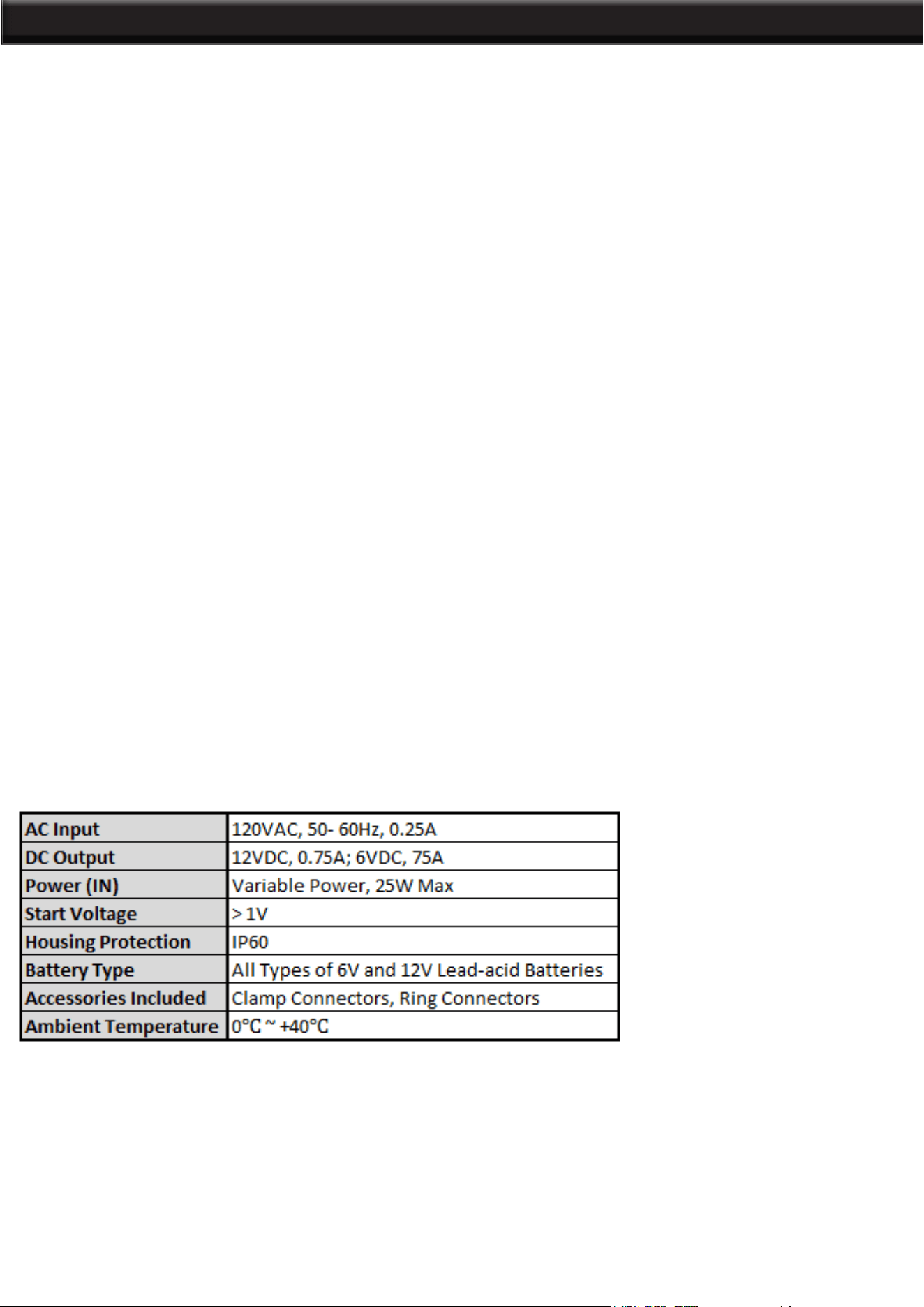
7) Following is the charger’s technical specication:
ABOUT THE CHARGER
SPECIFICATIONS
CONNECTING TO THE BATTERY
1) Identify polarity of battery posts. The positive battery terminal is typically marked by these letters or symbol
(POS,P,+). The negative battery terminal is typically marked by these letters or symbol (NEG,N,-).
2) Do not make any connections to the carburetor, fuel lines, or thin metal parts.
3) Identify if you have a negative or positive grounded vehicle. This can be done by identifying which battery
post (NEG or POS) is connected to the chassis.
4) For a negative grounded vehicle (most common): connect the RED POSITIVE clamp / ring connector rst
to the positive battery terminal, then connect the BLACK NEGATIV clamp / ring connector to the negative
battery terminal or vehicle chassis.
3
OPERATION
5) For a positive grounded vehicle (very uncommon): connect the BLACK NEGATIV clamp / ring connector
rst to the negative battery terminal, then connect the RED POSITIVE clamp / ring connector to the positive
battery terminal or vehicle chassis.
6) When disconnecting, disconnect in the reverse sequence, removing the negative rst (or positive rst for
positive ground systems).
7) Follow these steps when using 12V accessory plug (Charger does not have this accessory): keep the
vehicle hood open. Connect the end of the 12V accessory plug to the charger; insert the 12V accessory plug
into the vehicle’s 12V outlet. If the vehicle’s ignition key has to be on in order for the 12V outlet to supply
/ receive power, turn the key, without starting the engine. 8) A marine (boat) battery must be removed and
charged on shore. To charge it on board requires equipment specially designed for marine use.
CHARGING MODES
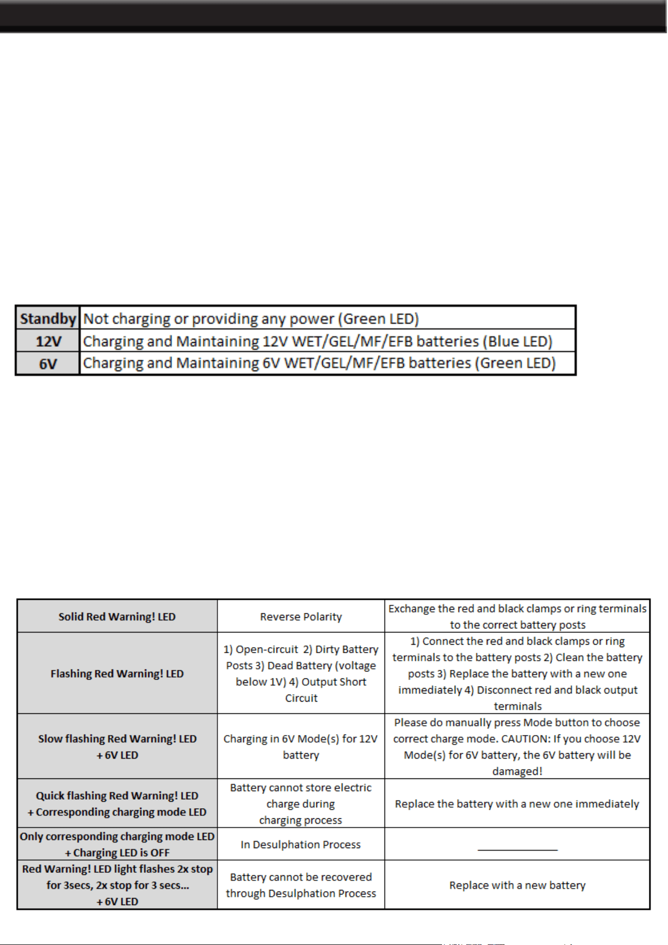
This battery charger has three modes: Standby,12V and 6V. Do not operate the charger until you conrm the
appropriate charge mode for your battery.
NOTICE: Make sure your battery to be charged / maintained is in good condition. The Charger cannot be
used to recover severely discharged batteries or dead batteries. How to deal with the batteries which are
deeply discharged, but in good condition?
1. Make sure the battery is in good condition (not dead) and was deeply discharged only. You can use the
battery analyzer to get the result if you have.
2. Jumpstart your vehicle or use a battery charger with recovery function to activate the battery until the
battery voltage increases to normal condition. For 12V batteries, the normal voltage is above 8 volt at least;
for 6V batteries, the normal voltage is above 4 volt at least.
3. Use the Charger / Maintainer do the rest charging and maintaining work.
LED COMMUNICATION OF ABNORMAL RESULTS
4
DISCLAIMER
THE MANUFACTURER AND/OR DISTRIBUTOR HAS PROVIDED THE PARTS LIST AND ASSEMBLY
DIAGRAM IN THIS MANUAL AS A REFERENCE TOOL ONLY. NEITHER THE MANUFACTURER OR
DISTRIBUTOR MAKES ANY REPRESENTATION OR WARRANTY OF ANY KIND TO THE BUYER THAT
HE OR SHE IS QUALIFIED TO MAKE ANY REPAIRS TO THE PRODUCT, OR THAT HE OR SHE IS
QUALIFIED TO REPLACE ANY PARTS OF THE PRODUCT. IN FACT, THE MANUFACTURER AND/OR
DISTRIBUTOR EXPRESSLY STATES THAT ALL REPAIRS AND PARTS REPLACEMENTS SHOULD BE
UNDERTAKEN BY CERTIFIED AND LICENSED TECHNICIANS, AND NOT BY THE BUYER. THE BUYER
ASSUMES ALL RISK AND LIABILITY ARISING OUT OF HIS OR HER REPAIRS TO THE ORIGINAL
PRODUCT OR REPLACEMENT PARTS THERETO, OR ARISING OUT OF HIS OR HER INSTALLATION
OF REPLACEMENT PARTS THERETO.
Record Product’s Serial Number Here:
Note: If product has no serial number, record month and year of purchase instead.
Note: Some parts are listed and shown for illustration purposes only and are not available individually
as replacement parts.
PLEASE READ THE FOLLOWING CAREFULLY
PRODUCT MADE IN CHINA