AC-DANTE-AMP-2CH
User Manual
2-CHANNEL DANTE DECODER/POWER AMPLIFIER

2
Table of Contents
Important Safety Instructions ...................................................................................................................................................................3
Safety Classifications in this Document ....................................................................................................................................... 3
Safety Statements ................................................................................................................................................................................... 4
Introduction ........................................................................................................................................................................................................5
Features ........................................................................................................................................................................................................ 5
Key Benefits................................................................................................................................................................................................. 5
Product Overview ...........................................................................................................................................................................................6
Box Contents .............................................................................................................................................................................................. 6
Technical Specifications....................................................................................................................................................................... 6
AC-DANTE-AMP-2CH FRONT AND REAR PANEL OVERVIEW ....................................................................................... 8
Dante Port Wiring and LAN Port Wiring ........................................................................................................................................... 10
Line Level Audio Output Wiring Configuration ............................................................................................................................. 11
Connecting the Device .............................................................................................................................................................................. 12
RS-232 Wiring and Control ................................................................................................................................................................ 13
Device Configuration ................................................................................................................................................................................. 14
Basic Navigation and Dante Flow Subscription ..................................................................................................................... 14
Changing Device Name and Encoding Configuration ....................................................................................................... 16
Network Configuration ........................................................................................................................................................................ 17
AES67 Audio Stream Configuration ............................................................................................................................................. 18
AC-DANTE-AMP-2CH WebUI ............................................................................................................................................................... 19
AC-DANTE-AMP-2CH Speaker Level Settings ....................................................................................................................... 19
AC-DANTE-AMP-2CH Line Out Settings .................................................................................................................................... 20
AC-DANTE-AMP-2CH IP / RS-232 CONTROL ......................................................................................................................... 21
AC-DANTE-AMP-2CH Hardware / Update ............................................................................................................................... 23
Troubleshooting ............................................................................................................................................................................................ 24
Maintenance .................................................................................................................................................................................................. 24
Damage Requiring Service ..................................................................................................................................................................... 25
Support.............................................................................................................................................................................................................. 25
Warranty........................................................................................................................................................................................................... 25
Obtaining an RMA .................................................................................................................................................................................. 26
Shipping ...................................................................................................................................................................................................... 26
Exclusive Remedy .................................................................................................................................................................................. 27

3
Important Safety Instructions
Before installing, configuring, and operating this device and other vendor equipment, AVPro Edge
strongly recommends that each dealer, integrator, installer, and all other necessary personnel access
and read all the required technical documentation, which can be located by visiting AVProEdge.com
.
Read and understand all safety instructions, cautions, and warnings in this document and the labels on
the equipment.
Safety Classifications in this Document
Note:
Provides special information for installing, configuring, and operating this
device, or this device with associated equipment.
Tip:
Provides suggestions and considerations for installing, configuring, and
operating this device.
Important:
Provides special information that is critical for installing, configuring, and
operating this device, or this device with associated equipment.
Caution:
Provides special information to avoid situations that may result in damage
to the device or associated equipment.
Warning:
Provides special information to avoid situations where improper
installation may endanger the installer, end user, or those unaware.
Electrical Shock Prevention
Electric Shock:
Provides special information critical for installing, configuring, and
operating this device or associated equipment safely.
Electrical Disconnect:
Provides special information to prevent situations that may result in
damage to the device and associated equipment or pose a personnel
hazard.
Weight Injury Prevention
Weight Injury:
Safe installation for some devices may require two-person handling.
Attempts otherwise may result in injury.

4
Safety Statements
Follow all of the safety instructions listed below and apply them accordingly. Additional safety
information will be included where applicable.
1 Read and keep these instructions.
2 Heed and follow all warnings.
3 Clean devices and equipment only with a dry cloth.
4 Devices not designed for exposure to moisture should NEVER be installed in prone locations.
5 Do not block any ventilation openings or install a device in a manner cautioned against.
6 This device or accessories should never be exposed to open flames or excessive heat.
7 Only use attachments and accessories specified by AVPro Edge.
8 Install by these instructions provided by AVPro Edge.
9 Do not install near a potential source of inordinate heat that may cause this device to operate
outside its normal thermal capacity.
10 Do not defeat the safety purpose of the polarized/grounding-type plug. A polarized plug has
two blades, one wider than the other. A grounding-type plug has two blades and a third
grounding prong. The wide blade, or third prong, is provided for your safety.
11 Position all device power cords in such a manner that prevent the potential for any sharp
radius bends, particularly where they exit the device or at the mains power connection.
12 Provide proper protection and isolation from dangerous surge conditions and disconnect
devices from power if they are unused for a long period.
13 To reduce the risk of electrical shock, never contact the device or power cord with damp
hands.
14 Safe installation for some devices may require two-person handling. Attempts otherwise may
result in injury
.
15 There are NO internal user-serviceable parts. Should this device function erratically or not
appear to be operating as intended, please contact AVPro Edge Technical Support. If the
power cord/power supply has been compromised, do not attempt or continue operating.
5
Introduction
The AC-DANTE-AMP-2CH is a combination 25W/RMS (@4 Ω, 12.5 W/RMS @ 8 Ω ) 2-channel audio power
amplifier and Dante Audio (only) decoder. Encrypted Dante audio is input via the designated Dante
Audio network RJ-45 port, undergoes decoding from Dante digital into analog, and outputs speaker level
signal from a pair of secured, 2-pin terminal block connectors, plus line level audio by way of a 5-pin
terminal block connector. AC-DANTE-AMP-2CH supports sampling rates of 44.1kHz, 48kHz, 88.2kHz, and
96kHz with 16-, 24-, and 32-bit word lengths encoded in either the Dante audio or AES67 format.
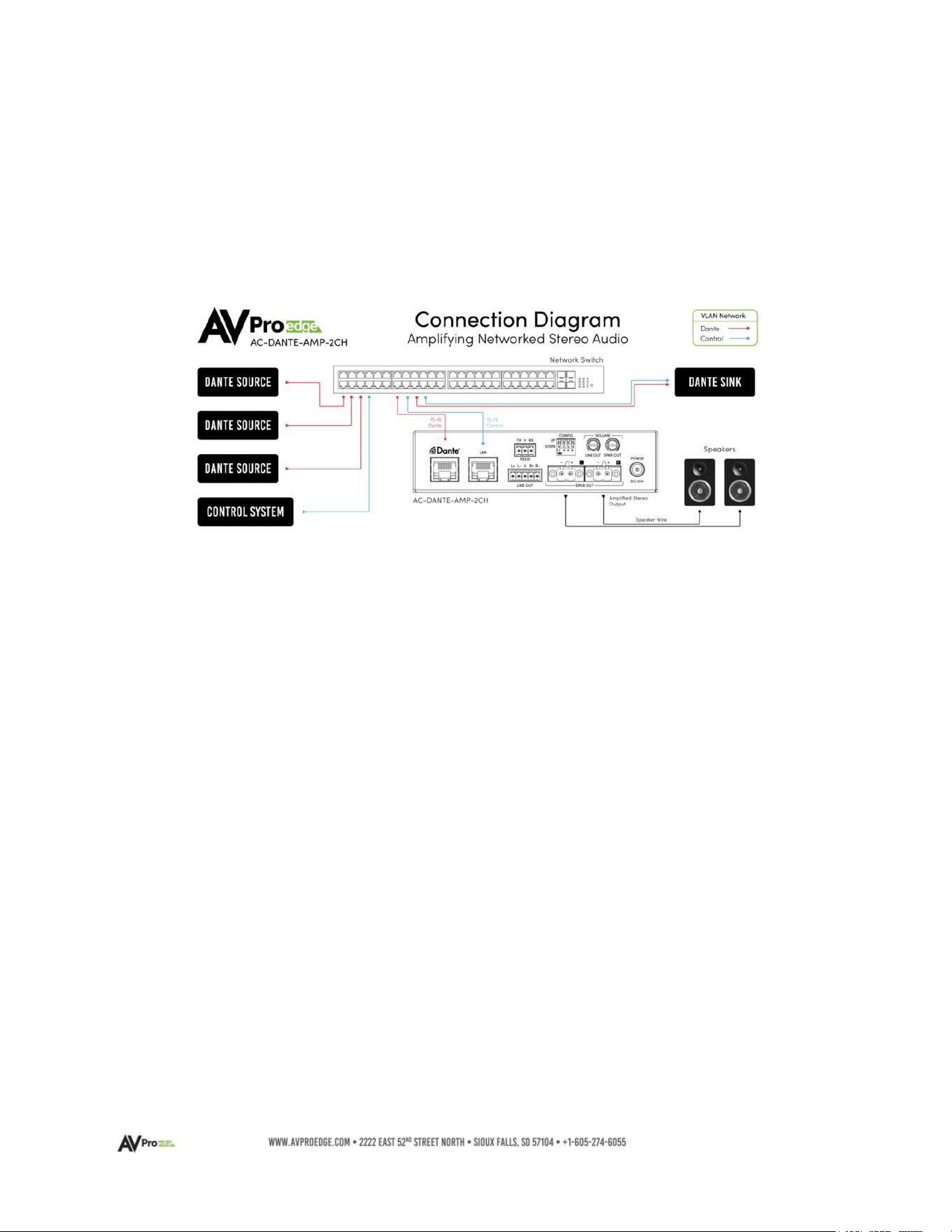
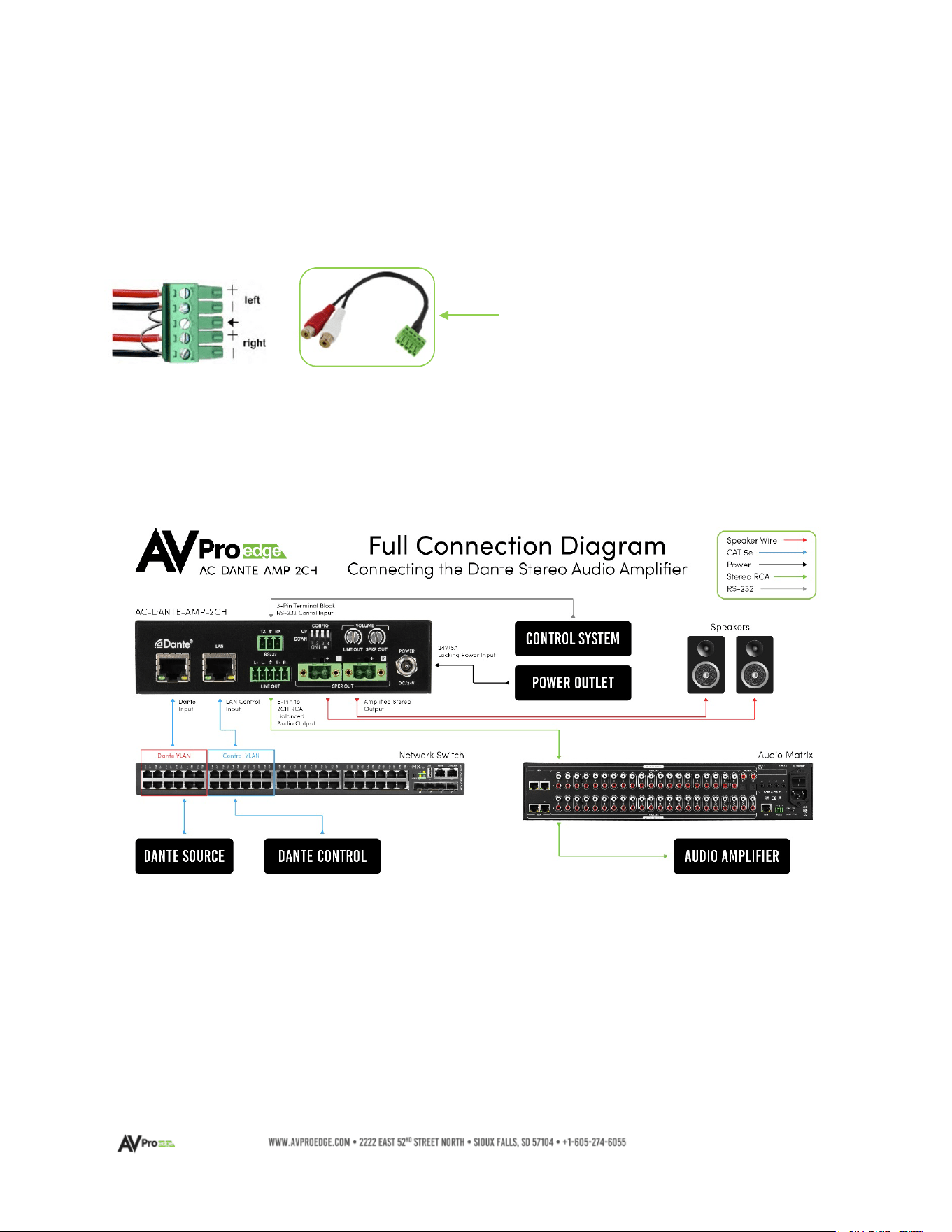
The diagram below shows the typical connection scenario for the AC-DANTE-AMP-2CH
Features
• Combination Dante Audio decoder and power amplifier with simultaneous line out
(configurable) to power local speakers and pass the decoded signal to a multi-channel
distribution device or outboard power amplifier.
• Balanced and unbalanced Line Output
• Power amplifier output of 25 watts RMS into 8 ohms, or 12.5 watts into 4 ohms
• IP or RS-232 Control
• Line and Speaker Level output potentiometers at device rear panel
• Supports multi-sampling rates and bit word lengths
Key Benefits
• Versatile design supports amplified and preamp-level signals
• Supports sampling rates of 44.1kHz, 48kHz, 88.2kHz, and 96kHz
• Supports 16-, 24-, and 32-bit word lengths
• Decodes Dante Audio or AES67 formats
• Compact chassis enables easy, discrete, power amp localization
• Front panel Mini-OLED window displays speaker level, line level volume, plus IP address
• Front panel Clip indicator provides amplifier overdrive information
6
Product Overview
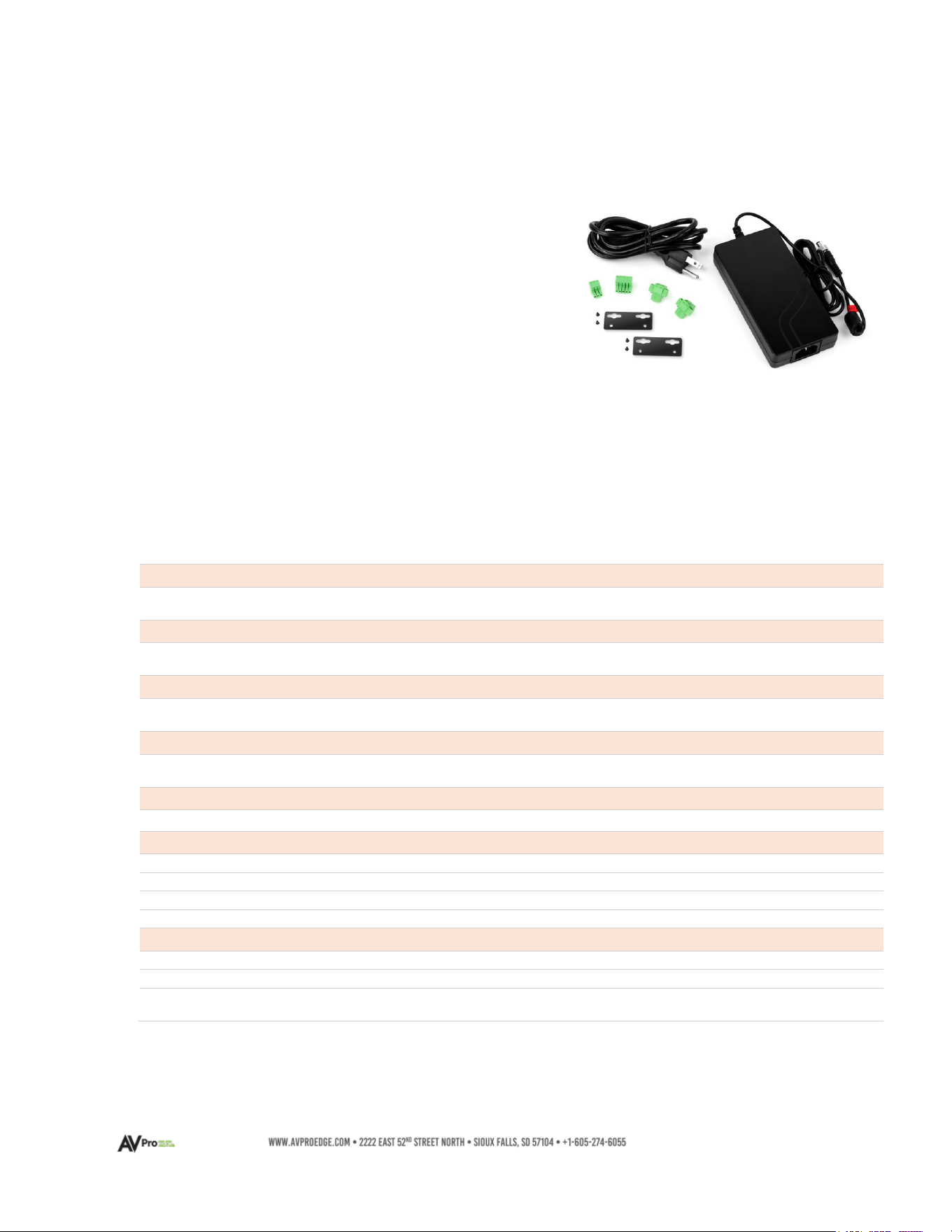
Box Contents
(1x) AC-DANTE-AMP-2CH
(1x) 24V-5.0A Power Supply
(1x) 3-Pin Terminal Block Connector for RS-232 Port
(1x) 5-Pin Terminal Block Connector for Line Level Output
(2x) Secured, 2-Pin Speaker Terminal Block Connection
(2x) Mounting Brackets
(4x) Mounting Screws
Technical Specifications
Audio Output - Speaker Level
Audio Output Power
25W/RMS @ 4 Ohms
12.5W/RMS@ 8 Ohms
Audio Output – Line Level
Line Level Voltage Output
1VRMS maximum output in Balanced mode
1VRMS maximum output in Unbalanced mode
Sampling Frequencies and Word Bit Depths
Sampling Frequencies
Word Bit Depths
44.1kHz, 48kHz, 88.2kHz, 96 kHz
16-bit, 24-bit, 32-bit
Analog Audio Output Connections
Line Level Output
Speaker Level Output
1x 5-pin terminal block
2x Secured, 2-pin terminal block
Digital Audio Input Connections
Dante Audio
1x RJ-45
Device Control
RS-232
1x 3-pin terminal block
IP
1x RJ-45
Line Level Output
1x Stereo volume potentiometer
Speaker Level Output
1x Stereo volume potentiometer
Power
Power Input
1x 2-pin, secure locking ring
Power Consumption (total)
Watts maximum
External AC Power Supply Unit Adapter
Input: 100-240VAC, 50/60Hz, 0.5A
Output: 24VDC, 5A

7
Environmental
Operating Temperature
23° to 125°F (-5° to 51°C)
Storage Temperature
-4° to 140°F (-20° to 60°C)
Operating Humidity
5% to 90% RH (Condensation-free)
Dimensions
Mounting
Furniture mount support with included brackets
Width/Depth/Height (DEVICE)
mm: 140 X 90 X 35
inch: 5.51 X 3.54 X 1.38
Width/Depth/Height (BOXED)
mm: 193 X 136 X 41
inch: 7.6 X 5.35 X 1.62
Weight (DEVICE)
0.50 LBS/0.23 KG
Weight (BOXED)
0.85 LBS/0.38 KG
Product Warranty
10 Years
Parts & Labor
Design and Specifications are subject to change without notice. Dimensions may not be definitive.
8
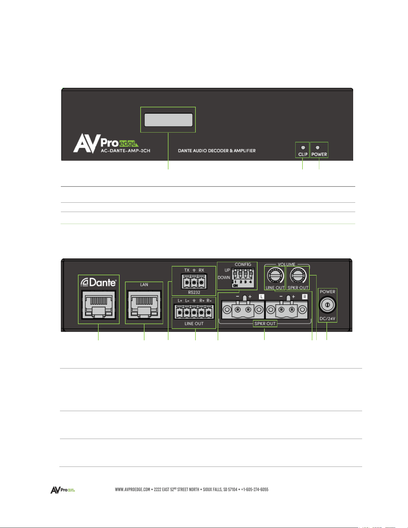
AC-DANTE-AMP-2CH FRONT AND REAR PANEL OVERVIEW
AC-DANTE-AMP-2CH – Front Panel
AC-DANTE-AMP-2CH – Rear Panel
1
D
ANTE NETWORK
A
UDIO PORT
• 8-pin RJ-45 female connector port
• Encoded Dante™ digital audio input port
• Connects to the network switch with CAT5e (or better)
cable
2
LAN
PORT
• 8-pin RJ-45 female connector port
• Connect to LAN, router, or 3
rd
party control system
3
RS
-232 PORT
•
3-pin terminal block connector port
• Control port for serial RS-232 connection
1
OLED
DISPLAY
• Displays the Speaker Volume, Line Out Volume,
and IP Address
2
CLIP INDICATOR
• Illuminated Red during a fault condition
3
POWER INDICATOR
• Illuminated Green when power is present
1 2 3
1 2 3 4 5 6 7/8 9

9
4
L
INE LEVEL
A
UDIO OUTPUT
•
5-pin terminal block connection
• Balanced or unbalanced 2-channel outputs
• 1VRMS balanced mode maximum output
• 1VRMS unbalanced mode maximum output
5
CONFIG
• Configuration Dip Switches (UP – Off / DOWN – On)
• Dip 1 - Boosts Line Level Output Gain by +3 dB
• Dip 2 - Reverses Line Level Output Channels
• Dip 3 - Front Panel OLED Display Timeout Interval Adjust
Up – Display turns off automatically 3 minutes after
last user input activity (IP/RS-232 commands)
Down – Display is always active
• Dip 4 - Volume Control Interface Accessibility
Up – Remote access plus rear panel controls
Down – Rear panel controls only
6
SPEAKER LEVEL OUTPUT
•
Left and Right channels
• 2-pin terminal block speaker output ports
7
LINE LEVEL OUTPUT
VOLUME CONTROL
•
Local Line Level volume output adjustment knob
• Adjust clockwise to increase line-level audio output
• Adjust counterclockwise to decrease line-level audio
output
NOTE: Enabling Line Out Volume Following, or Lineout
Volume Lock disables the use of this control
8
SPEAKER LEVEL
OUTPUT
VOLUME CONTROL
•
Local Speaker Level output volume adjustment knob
• Adjust clockwise to increase speaker-level audio output
• Adjust counterclockwise to decrease speaker-level audio
output
NOTE: Enabling Speaker Volume Lock disables the use of
this control
POWER
• DC 24V/5A Locking Ring, Power Input
10
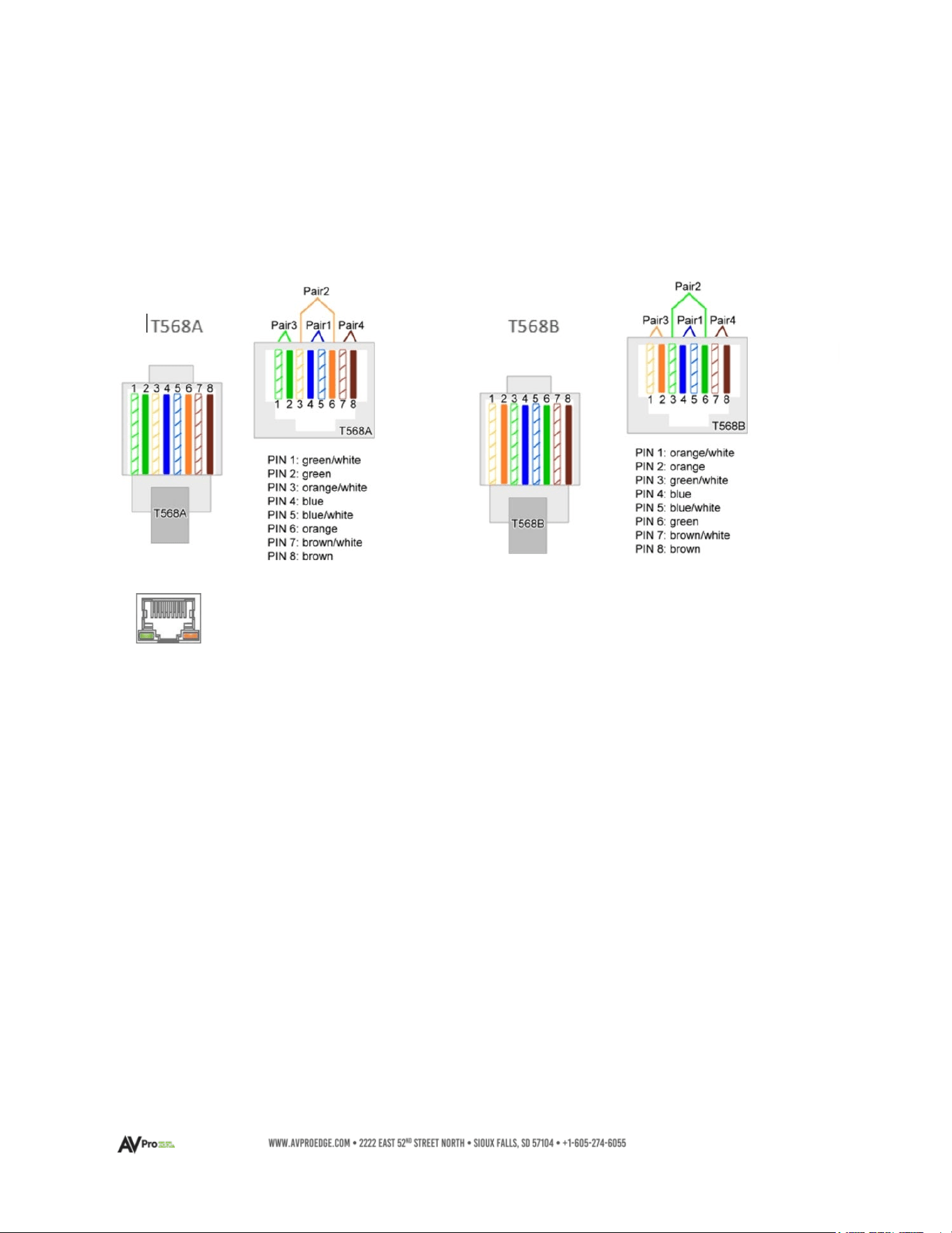
Dante Port Wiring and LAN Port Wiring
The DANTE audio input port on the AC-DANTE-AMP-2CH utilizes a standard RJ-45 connection. For
optimal performance, CAT5e (or better) cabling is recommended, based on the TIA/EIA T568A or the
T568B standard for wiring twisted pair cable.
Use these same wiring conventions are used for the LAN port.
LEFT LED (Green) – Link/Activity
Indicates there is an active link between the AC-DANTE-AMP-2CH and the sending end. Solid
green indicates the AC-DANTE-AMP-2CH and the sending device are identified with both devices
sharing communications.
RIGHT LED (Amber) – Link Status
Indicates data is present between the AC-DANTE-AMP-2CH and the sending end (typically a
network switch). Continuously blinking amber indicates normal operational status.
If either LED is not illuminating, check the following:
• Ensure the AC-DANTE-AMP-2CH front panel power status light is illuminated green.
• Verify cable length is within a maximum distance limit of 100 meters/328 feet.
• Connect the AC-DANTE-AMP-2CH directly to the network switch, bypassing all possible
signal interruption points, such as patch panels, couplers, and punch-down blocks.
• Re-terminate connector ends. Use high-quality, standard RJ-45 connectors and avoid
push-through “EZ” type ends, as these leave exposed copper wiring at the tips that may
introduce signal interference or cross-talk.
• Contact AVPro Edge Technical Support if these suggestions do not work.
The DANTE audio output port features two status indicator LEDs to confirm
active connections while operational and during troubleshooting.
11
Line Level Audio Output Wiring Configuration
The analog Line Level audio output port on the AC-DANTE-AMP-2CH outputs 2-channel balanced
audio, ideal for passing the signal to an analog distribution amplifier while the AC-DANTE-AMP-2CH
internal amplifier powers local speakers. The balanced audio output may be converted into a 2-
channel unbalanced audio signal by preparing the cabling using jumpers as shown below left:
Connections to the AC-DANTE-AMP-2CH
A pre-configured 5-Pin to RCA pair
adapter is available, purchased
separately, as SKU: AC-CABLE-5PIN-
2CH
12
Connecting the Device
1 Connect the cable attached to the 24VDC-5A power supply housing to the AC-DANTE-
AMP-2CH Decoder/Amplifier DC/5V input port. Connect the AC mains power cord to the
24VDC-5A power supply adapter and plug into a properly grounded power outlet.
•
Note:
The AC-DANTE-AMP-2CH does not support PoC or PoE. It is required to be
locally powered using the provided 24V-5A power supply unit.
The green, front panel POWER LED will illuminate indicating the AC-DANTE-AMP-2CH is
powered on.
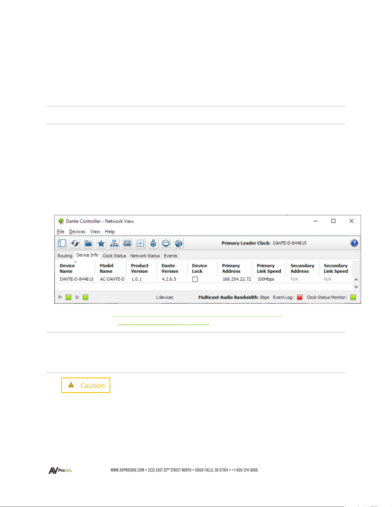
2 Connect a CAT5e (or better) cable between a computer running the Dante® Controller
software and the network switch.
3 Connect a CAT5e (or better) cable between the DANTE® port on the AC-DANTE-AMP-
2CH and the network switch. The AC-DANTE-AMP-2CH will be automatically discovered
using the Dante® Controller software.
• Note: Device names depicted in diagrams may differ from the actual device
referenced throughout this manual.
• Note:
Both the computer running Dante® Controller software and the AC-DANTE-
AMP-2CH must have a physical connection to the Dante™ network for the
AC-DANTE-AMP-2CH to be discovered by Dante™ Controller.
DO NOT MAKE AMPLIFIER CONNECTIONS WITH THE UNIT POWERED ON!
4 If the AC-DANTE-AMP-2CH will be powering passive loudspeakers, strip back a ¼”
portion of the left channel speaker wire marked “+” and insert it into the port on one of
the supplied 2-pin terminal blocks that will correspond with the LEFT “+” speaker output
lugs on the amplifier. Secure in place using the captive screw; avoid overtightening.
Repeat this process with the ”–“ wire and the LEFT “–“ block port. Duplicate this
process for the Right Channel speaker wire. Push both prepared terminal blocks into
their matching ports on the AC-DANTE-AMP-2CH.
13
Observe speaker impedances. Only use speakers where the total impedance
will remain constant between 4 Ohms and 8 Ohms per channel. Multiple
speakers per channel must maintain an average between 4 Ohms and 8
Ohms. Both channels must present the same impedance load to the
amplifier. NEVER connect this amp using speaker level to a powered
speaker, regardless of whether it is designed to accept a speaker-level input.
5 If the AC-DANTE-AMP-2CH will be connected to a multi-zone distributed audio amplifier,
u
se the supplied 5-pin terminal block to prepare an interface cable appropriate to facilitate
the correct connection between the devices. Some distributed products have balanced
inputs requiring direct-wire input or an identical 5-pin terminal block. Observe polarity
when connecting or assembling a cable.
If connecting the AC-DANTE-AMP-2CH to a device with an RCA-type input, AVPro Edge
recommends using the AC-CABLE-5PIN-2CH balanced to an unbalanced pre-made adapter.
When modifying a cable, follow the instructions in the section above titled Line Level
Audio Output Wiring Configuration for converting the 5-pin terminal block from balanced
output to unbalanced output. Observe polarity when connecting or when assembling a
cable.
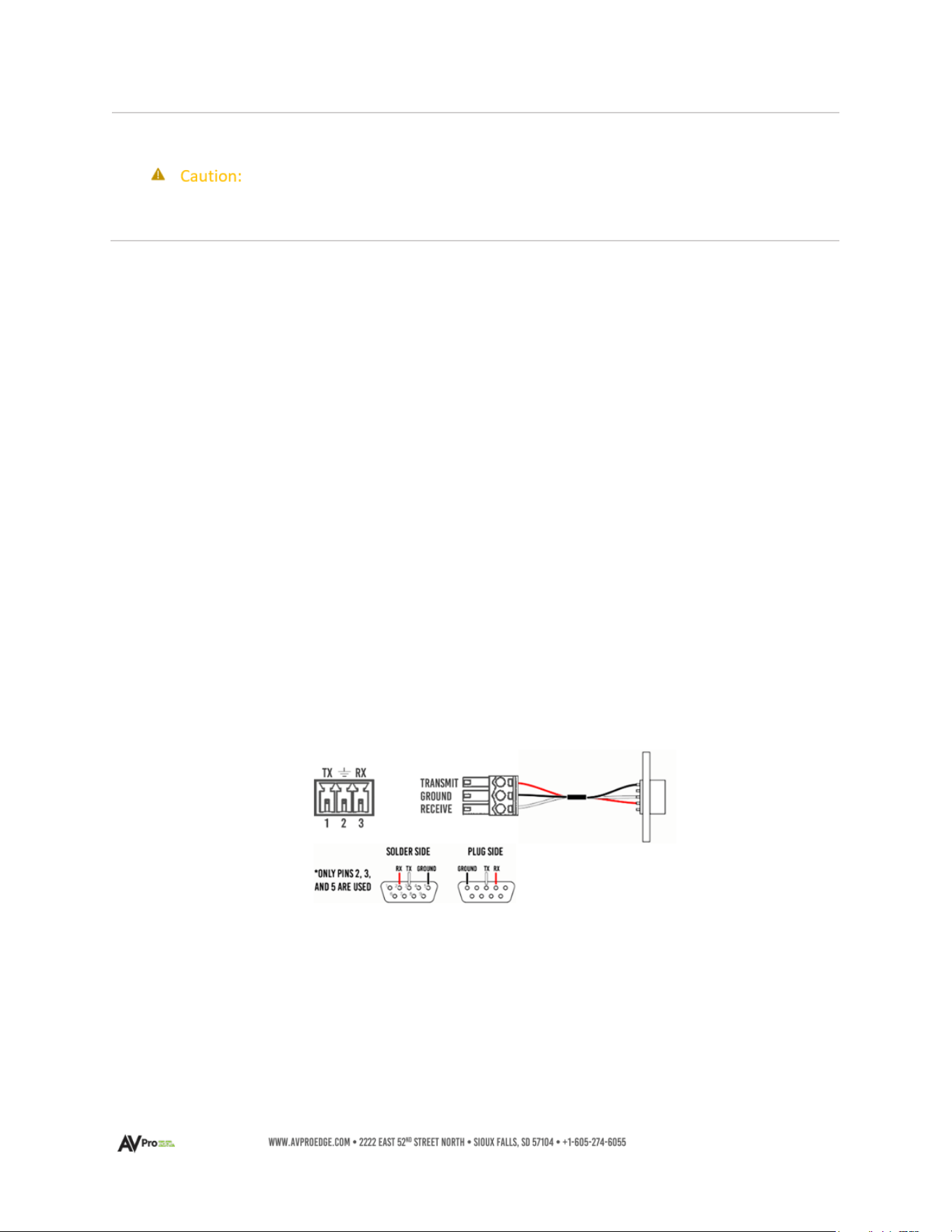
RS-232 Wiring and Control
The RS-232 control port on both the AC-DANTE-AMP-2CH is used to pass bidirectional control
signals to and from any RS-232-compatible device.
Serial control connections are made using the provided 3-pin terminal block connector. The wire
slips into the hole and is captively locked by the screw located on the top side of the connector.
Wiring from the 3-pin terminal block connects with pins 2, 3, and 5 when converting to a
standard DB-9 connector. If the control signal device is not equipped with a DB-9 port, use a
suitable adapter for the control device protocol port type required.
Use the LAN port to control the AC-DANTE-AMP-2CH over IP. The wiring configurations are
Illustrated on page 10.
14
Device Configuration
Configuring the AC-Dante-AMP-2CH requires the installation of Audinate’s Dante Controller software
onto a computer that will be connected to the Dante network.
Dante Controller is used to configure network settings, signal latency, audio encoding parameters,
Dante flow subscriptions, and AES67 audio support. The latest version of Dante Controller may be
found at: https://www.audinate.com/products/software/dante-controller
; including supplementary
instructions that may be obtained via the online help support tool, located under the Help tab in
Dante Controller.
Basic Navigation and Dante Flow Subscription
By default, Dante Controller opens with the Routing tab displaying Dante devices discovered on
the network and organized according to transmitter or receiver status. Signal routing from
Dante encoders (transmitters) to Dante decoders (receivers) is achieved by clicking the boxes
located where transmit and receive channels intersect. Successful subscriptions are denoted by
green check mark icons.
15
1
Transmitters
• Discovered Dante encoders
2
Receivers
• Discovered Dante decoders
3
+/
-
• Select the (+) to expand or (-) to collapse view
4
Device Name
•
Displays the name assigned to the Dante device
• Device name is customizable in Device View
• Double-click to open Device View
5
Channel Name
•
Displays the name of the Dante audio channel
• Channel name customizable in Device View
•
Double click associated Device Name to open Device View
6
Subscription
Window
• Tip:
Hovering the mouse over the
subscription indicator symbol
will provide further details
about the subscription, which
may be useful in
troubleshooting
• Click the box to create a unicast subscription between the
overlapping
Subscription in process
Subscription successful
Subscription error
Subscription warning
Device part way through setting up a subscription
16
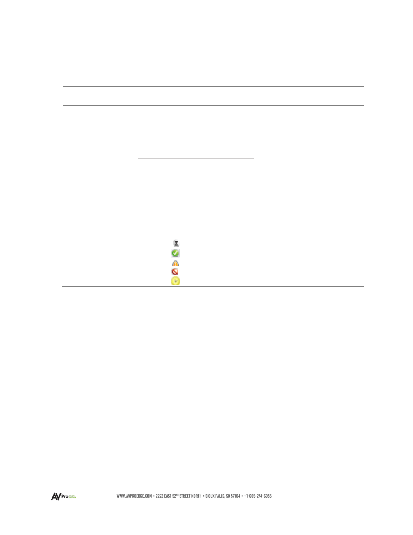
Changing Device Name and Encoding Configuration
To configure the AC-DANTE-AMP-2CH audio stream, open the Device View by double-clicking the
Device Name for the AC-DANTE-AMP-2CH and navigate to the Device Config Tab.
1
Device Name
• Device Name for the AC-DANTE-AMP-2CH
• Device Name can be changed by typing a
new name and then click apply
2
Sample
Rate
• Set AC-DANTE-AMP-2CH PCM sample rate
• 44.1, 48, 88.2, 96 kHz sample rates supported
3
Encoding
• Set the bit depth of the sampled input signal
•
16-, 24-, and 32-bit sampling supported
4
Clocking
• Enable/Disable unicast delay requests
5
Device Latency
•
Set latency for subscribed Dante flows
• 1, 2, and 5-millisecond latencies are supported
6
Reboot Device
• Reboot the AC-DANTE-AMP-2CH
7
Clear Config
• Factory Reset Settings
17
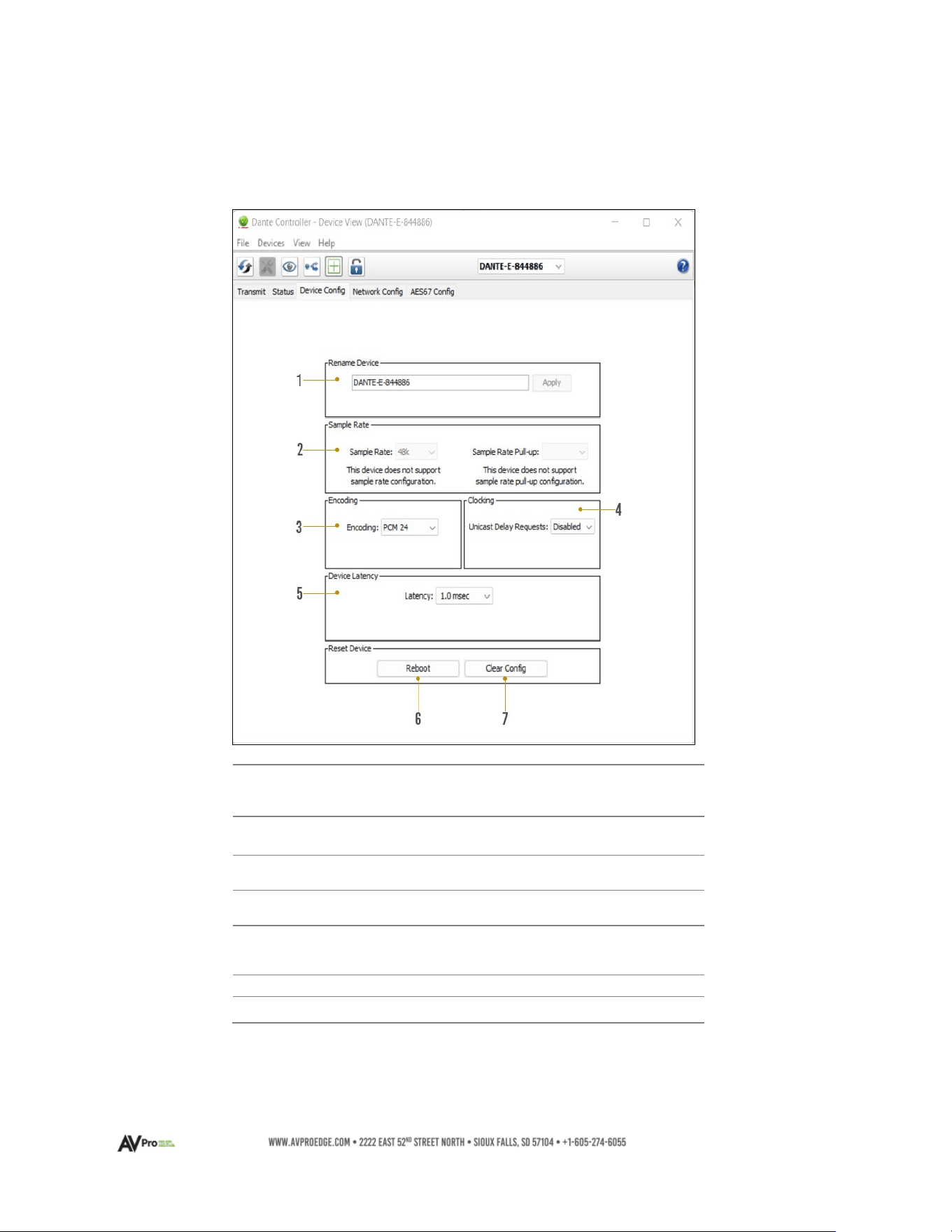
Network Configuration
DHCP for the AC-DANTE-AMP-2CH is enabled by default and will automatically be assigned an IP
address when connected to the Dante network. Additionally, a static IP address can be assigned
by opening the Device View for the AC-DANTE-D and navigating to the Network Config tab.
1
Automatic IP
Assignment
• Check this button to enable DHCP for
automatic IP address assignment
2
Manual IP
Assignment
• Check this button to enable manual
(static) IP addressing
3
IP Address
•
Enter the desired IP address
4
Subnet
Mask
•
Enter the desired subnet mask
5
DNS Server
•
Enter the domain name server
6
Default Gateway
• Enter the default gateway
7
Reboot Device
• Reboot the AC-DANTE-AMP-2CH
8
Clear Config
• Factory reset the AC-DANTE-AMP-2CH
Manually setting the AC-DANTE-AMP-2CH IP address to a
different subnet from the Dante Controller computer will
result in a loss of communication between the Dante
Controller and the AC-DANTE-AMP-2CH
18
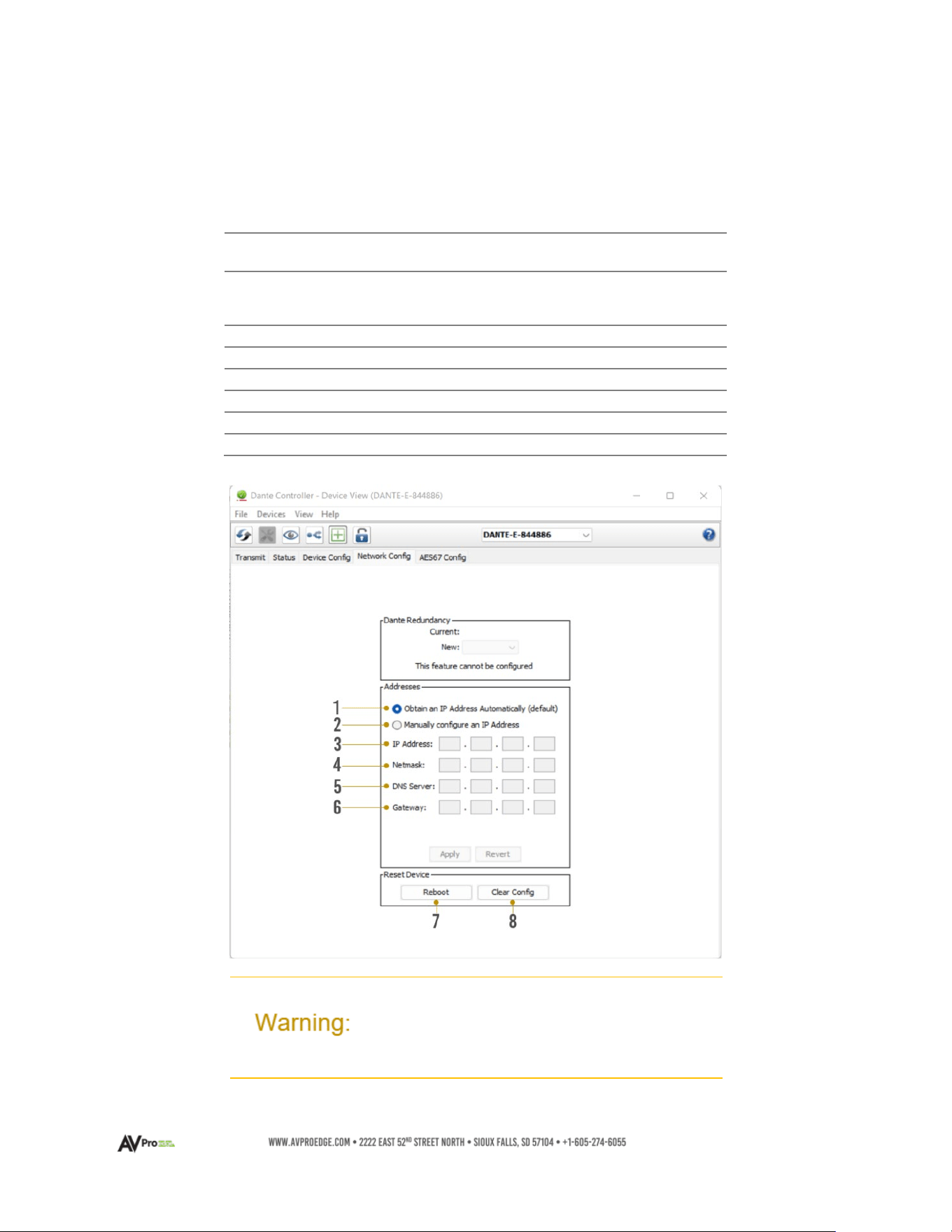
AES67 Audio Stream Configuration
The AC-DANTE-AMP-2CH supports multicast reception of AES67-encoded audio to compatible
non-Dante devices. AES67 multicast reception can be configured by opening the Device View by
double-clicking the AC-DANTE-AMP-2CH Device Name and navigating to the AES67 Config tab.
1
AES67 Mode
•
Enable/Disable AES67
multicast flows for
compatible non-Dante
devices
2
RTP Multicast
Address Prefix
• Displays current RTP
multicast prefix
• Type in a new RTP
multicast prefix and click
Set to apply
3
Reboot
• Reboot the AC-DANTE-
AMP-2CH
4
Clear Config
• Factory Reset the AC-
DANTE-AMP-2CH
19
AC-DANTE-AMP-2CH WebUI
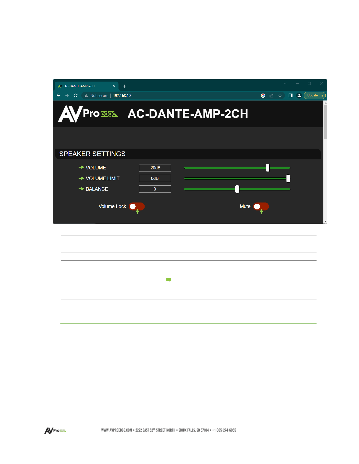
AC-DANTE-AMP-2CH Speaker Level Settings
1
VOLUME
• Adjust the speaker output level
2
VOLUME LIMIT
• Adjust the maximum speaker output level
3
BALANCE
• Adjust left/right speaker balance
4
VOLUME LOCK
• On (Green) – Volume adjustments are disabled
• Off (Red) – Volume can be adjusted
Volume Limit, Balance, and Mute remain
adjustable regardless of the Volume Lock
state
5
MUTE
•
On (Green) – Speaker output is muted
• Off (Red) – Speaker output is equal to the
current
volume setting
Note:
1
3
2
4
5
20
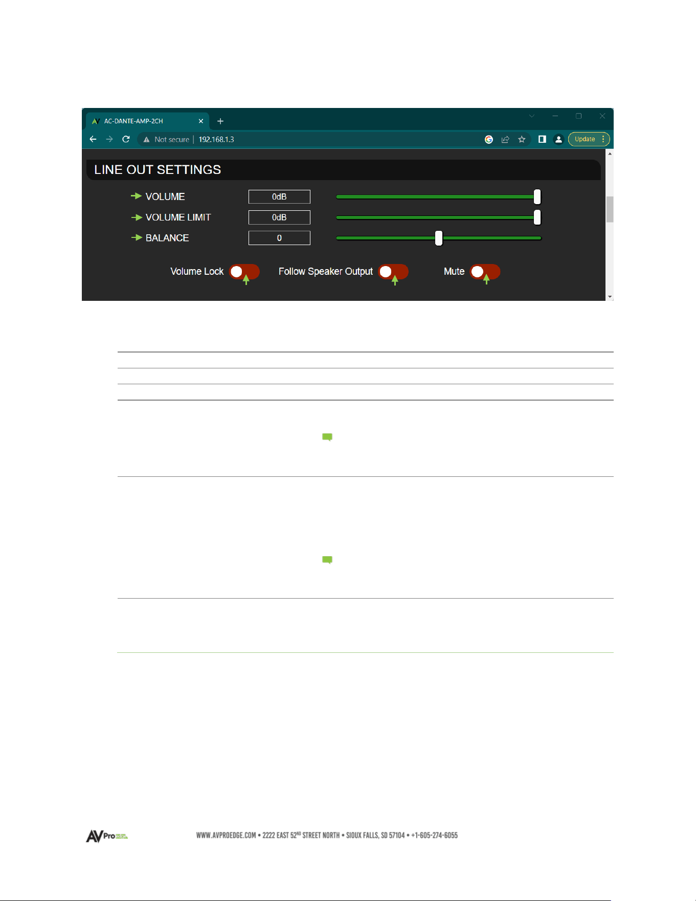
AC-DANTE-AMP-2CH Line Out Settings
1
VOLUME
• Adjusts the line level output
2
VOLUME LIMIT
• Adjusts the maximum line level output
3
BALANCE
• Adjusts the left/right line output balance
4
VOLUME LOCK
• On (Green) – Volume adjustments are disabled
• Off (Red) – Volume is adjustable
Volume Limit, Balance, and Mute remain
adjustable regardless of the Volume Lock
state
5
FOLLOW SPEAKER
OUTPUT
•
On (Green) – Lineout speaker volume is equal to
speaker volume level
• Off (Red) – Line level volume adjustment is
independent of the speaker level
setting
Volume Limit, Balance, and Mute remain
adjustable regardless of the Follow Speaker
Output state
6
MUTE
•
On (Green) – Line level output is muted
• Off (Red) – Line level output is equal to the
current volume setting
1
2
3
4
5
6
Note:
Note:
21
AC-DANTE-AMP-2CH IP / RS-232 CONTROL
1
HOSTNAME (mDNS)
• Displays the product mDNS hostname
2
IP ADDRESS
•
Displays the current IP address
3
SUBNET MASK
•
Displays the current Subnet Mask
4
GATEWAY
•
Displays the current Gateway
5
MAC ADDRESS
•
Displays the product MAC Address
6
DHCP
•
On (Green) – DHCP enabled
• Off (Red) – DHCP disabled. Static IP Address,
Static IP Mask, Static GW are settable
7
STATIC IP ADDRESS
•
Type in the desired Static IP Address
DHCP must be disabled and changes will not
take effect until ‘Apply’ is clicked
8
STATIC IP MASK
• Type in the desired Static IP Subnet Mask
DHCP must be disabled and changes will not
take effect until ‘Apply’ is clicked
9
STATIC GW
•
Type in the desired Static IP Gateway
DHCP must be disabled and changes will not
take effect until ‘Apply’ is clicked
10
APPLY
•
Apply changes to Static IP Address, Subnet Mask,
and Gateway to the device
11
TCP PORT
•
Type in the desired TCP port
Changes will not take effect until ‘Set TCP
Port’ is clicked and the device reboots.
Note: :
Note: :
1
4
2
3
5
6
7
8
9
10
11
12
13
Note: :
Note: :

22
12
SET TCP PORT
•
Apply changes to TCP port
Clicking will update and initiate a device
reboot.
13
RS232 BAUD RATE
•
Select desired RS232 Baud rate from the drop-
down menu
Note:
23
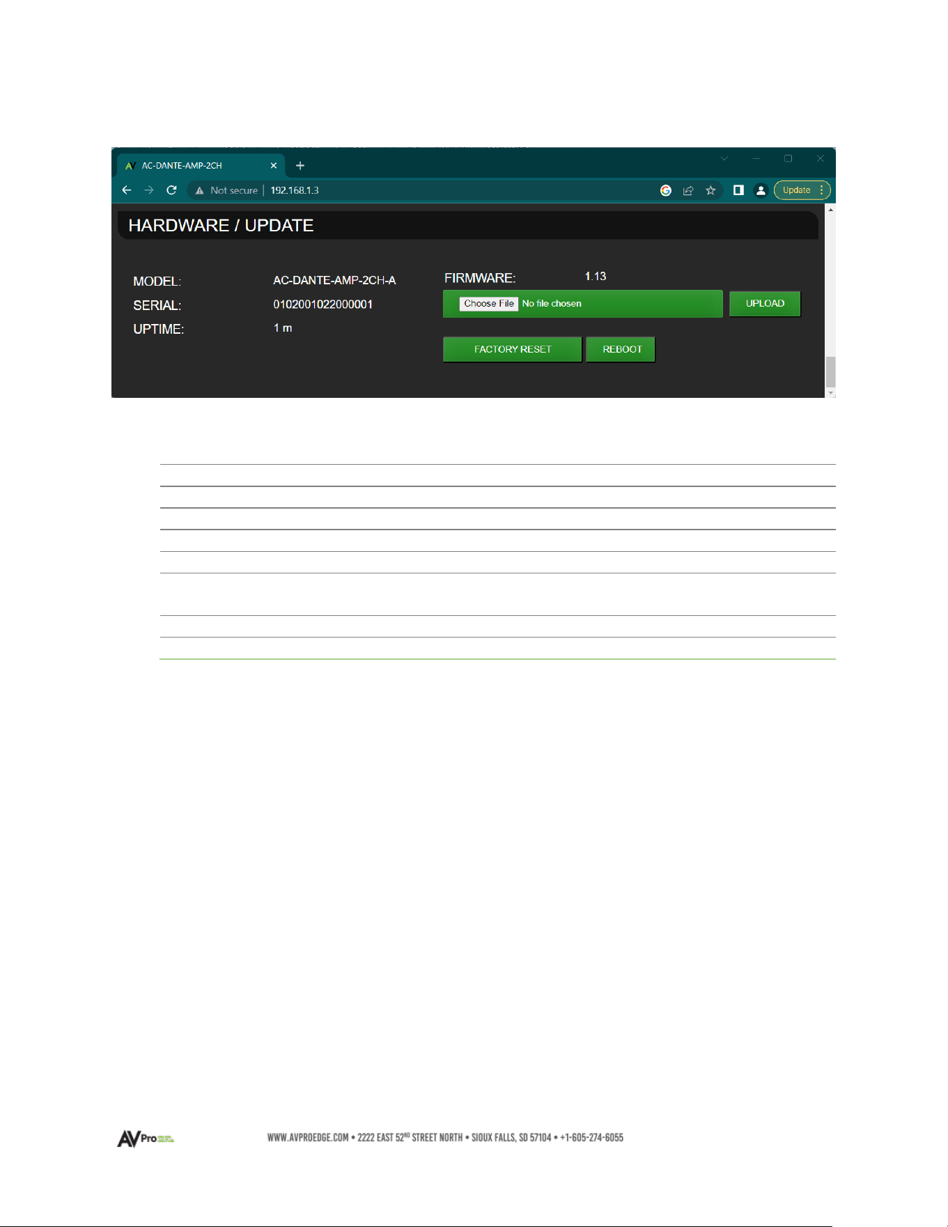
AC-DANTE-AMP-2CH Hardware / Update
1
MODEL
• Displays the product model number
2
SERIAL
• Displays the product serial number
3
UPTIME
• Displays the current runtime for the Web UI
4
FIRMWARE
• Displays the current installed firmware version
5
CHOOSE FILE
• Click to choose a firmware file to upload
6
UPLOAD
•
Upload the current selected firmware file to the
device
7
FACTORY RESET
•
Restore all settings to factory default
8
REBOOT
•
Reboot the device retaining current settings

24
Troubleshooting
• Verify Power – Check that the power supply is properly connected and is outputting 12V.
• Verify Connections – Check that all cables are properly connected and/or terminated where
applicable.
• Verify Terminations – Ensure you are using a minimum of CAT 5e UTP or STP without breaks such
as keystones, punch downs, or other interconnectors. Field terminatable plugs are
recommended.
• LOW Line Level Audio Out – Check the rear panel LINE OUT Control setting and the settings in
the API. Make sure the Volume Limit is set to 0 dB (if desired) and is not at a setting that is lowering
the overall device output.
• NO Line Level Audio Out – Check if the device has been placed into “Mute”. Make sure the 5-pin
terminal block for Line Out is seated firmly into the port. Verify the unit is powered on, and that
Dante data is streaming into the device. Check that the Dante RJ-45 connector is firmly seated
into the port.
• LOW Speaker Level Audio Out - Check the rear panel SPKR OUT Control setting and the settings
in the API. Make sure the Volume Limit is set to 0 dB (if desired) and is not at a setting that is
lowering the overall device output.
• NO Speaker Level Audio Out – Check if the device has been placed into “Mute”. Make sure the 2-
pin terminal block for each channel is seated firmly into each port. Verify the unit is powered on,
and that Dante data is streaming into the device. Make sure at each speaker and on each 2-pin
terminal block the wire is not frayed.
• The device cannot be controlled – Verify RS-232 connections are properly wired and are using
the pin arrangement depicted in the diagram on page 13. Make sure the 3-pin terminal block is
firmly seated into the RS-232 port. If IP controlled, verify all category wiring connections and the
cable is terminated to either the TIA/EIA T568A or T568B standards.
Maintenance
To ensure the reliable operation of these devices as well as protection for the safety of any person using
or handling these devices while powered, observe the following instructions:
• Only use the provided power supply. Replacements are available from AVPro Edge.
• Do not operate this device outside the specified temperature and humidity range given in the
above specifications.
• Ensure there is adequate ventilation to allow this device to operate efficiently. As it contains an
audio amplifier, it may run warmer than other AVPro Edge devices.
• Repair should only be carried out by a qualified professional. Contact AVPro Edge Tech Support if
any abnormal condition exists.
• Only use this device in a dry environment. Prevent contact with liquids or harmful chemicals and
do not attempt to operate if this has occurred.
• Clean this unit with a soft, dry cloth. No type of cleaning agent should be used on this device.

25
Damage Requiring Service
This device should be serviced only by AVPro Edge when:
• Objects or liquids have breached the interior of the device
• The device has been exposed to rain or moisture
• The device does not operate normally or exhibits a marked change in performance
• The device has been dropped or the housing is damaged
• Replace the DC power supply cord or AC adapter if they have suffered damage
Support
Should you experience any problems using this product, first refer to the Troubleshooting section of this
manual before contacting AVPro Technical Support. When calling in, the following information should be
provided:
• Full product name or model number and serial number
• Source of purchase
• Details of the issue and any conditions under which the issue is occurring
Warranty
The Basics
AVPro Edge warranties its products that are purchased from all authorized AVPro Edge resellers or
directly from AVPro Edge. Products are guaranteed to be free from manufacturing defects and are in
correct physical, electronic, and operational condition.
AVPro Edge has developed a warranty that anyone can get behind. We wanted to take all the “red
tape” out of a warranty and make it simple. Our 10 Year No BS Warranty depends on the following 3
conditions:
• If you are having trouble, call us. We will attempt to troubleshoot your issue over the phone.
• If troubleshooting determines the product has failed, we will replace it in advance, covering
shipping to you and back to AVPro Edge. You may also opt to have a unit repaired.
• We know you know what you are doing. We will not make you go through unnecessary steps
on-site with troubleshooting, but please allow Tech Support to perform the procedures
required to determine if a unit has failed or is in the process of doing so.
Coverage Details
AVPro Edge will replace or repair (at the customer’s choice) defective products. If the product is out of
stock or on backorder it may be replaced with a comparable product of equal value/feature set (if
available) or repaired.

26
Your warranty begins upon the receipt of the product (confirmed by tracking verification). If tracking
information is unavailable for any reason, the warranty will commence 30 days ARO (After Receipt of
Order). Coverage continues for a period of 10 years.
Red Tape
AVPro Edge is not responsible for untraceable purchases or those that were made outside of an
authorized channel.
If we conclude that a product or serial number has been tampered with as identified by the warranty
seal or physical examination, the warranty will be void. Additionally, if it has been determined the
failure is due to excessive physical damage (beyond normal wear & tear), the warranty may be voided
or prorated, based on the extent of the damage as determined by an AVPro Edge representative.
Damages caused by “acts of God” are not covered. This includes but is not limited to natural
disasters, power surges, storms, earthquakes, tornadoes, sinkholes, typhoons, tidal waves,
hurricanes, or any other uncontrollable nature-related event.
Damage caused by incorrect installation will not be covered. Use of a different or incorrect power
supply, inadequate cooling, improper cabling, inadequate protection, and static discharge are
examples of this.
Products installed or sold by a third party to AVPro Edge will be serviced by the authorized AVPro
Edge reseller. Accessories (IR cables, RS-232, power supplies, etc.) are not included in the warranty.
We will make acceptable efforts to source and supply replacements for defective accessories at a
discounted rate as needed.
Obtaining an RMA
Dealers, resellers, and installers can request an RMA from an AVPro Edge Technical Support
representative or Sales Engineer. Or you may email support@avproedge.com
or fill out the general
contact form at www.avproedge.com/contact.
End users may not request an RMA directly from AVPro Edge and will be referred back to the dealer,
reseller, or installer.
Shipping
For the USA (not including Alaska and Hawaii), shipping is covered on advanced replacements for
FedEx Ground (some expressed exceptions may apply). Defective product return shipping is covered
by AVPro Edge using an emailed return label. Items must be returned within 30 days of receipt of the
replacement product, after 40 days the customer will be billed. Other return shipping methods will not
be covered.
For international (and Alaska and Hawaii) return shipping costs will be the responsibility of the
returnee. Once the unit is scanned for return shipping AVPro Edge will ship the new replacement unit.
Limitation on Liability
The maximum liability of AVPro Global Holdings LLC under this limited warranty shall not exceed the
actual purchase price paid for the product. AVPro Global Holdings LLC is not responsible for direct,
special, incidental, or consequential damages resulting from any breach of warranty or condition, or
under any other legal theory to the maximum extent permitted by law. Taxes, Duties, VAT, and other
freight forwarding service charges are not covered or paid for by this warranty.
Obsolescence or incompatibility with newly invented technologies (after the manufacture of these
products) is not covered by this warranty. Obsolescence is defined as:

27
Peripherals are rendered obsolete when current technology does not support product repair or re-
manufacture. Obsolete products cannot be re-manufactured because advanced technologies
supersede original product manufacturer capabilities. Because of performance, price, and
functionality issues, product re-development is not an option.
Discontinued or out-of-production items will be credited at fair market value towards a current
product of equal or comparable capabilities and cost. Fair market value is determined by AVPro
Edge.
Exclusive Remedy
To the maximum extent permitted by law, this limited warranty and the remedies set forth above are
exclusive and in lieu of all other warranties, remedies, and conditions, whether oral or written, express
or implied. To the maximum extent permitted by law, AVPro Global Holdings LLC specifically disclaims
any and all implied warranties, including, without limitation, warranties of merchantability and fitness
for a particular purpose. If AVPro Global Holdings LLC cannot lawfully disclaim or exclude implied
warranties under applicable law, then all implied warranties covering this product, including
warranties of merchantability and fitness for a particular purpose, shall apply to this product as
provided under applicable law.
This warranty supersedes all other warranties, remedies, and conditions, whether oral or written,
express or implied.