
USER GUIDE
Upright Cabinets and Prep Tables
30671_B

WELCOME TO U-LINE
Congratulations on your U-Line purchase. This product is part of our U-Line by Desmon Collection. Made by our
sister company, Desmon in Italy, one of Europe’s leading producers of commercial refrigeration products. It is
designed and certified for commercial applications in North America.
U-Line offers products focused on functionality, style, and inspired innovations — paying close attention to even the smallest
details. Applications include residential, outdoor, ADA height compliant, marine, and commercial. Complete product categories
include Beverage Centers, Wine Refrigerators, Ice Machines, Refrigerators, Freezers, and Dispensers.
Our advanced refrigeration systems, large and flexible capacities, and Built-In to Stand Out
®
clean integrated look allow you
to preserve the right product, in the right place, at the right temperature. Since 2014, U-Line has been part of the Middleby
family of brands. Most products are designed, engineered, and assembled in Milwaukee, Wisconsin, USA, and select
products are available worldwide.
PRODUCT INFORMATION
Looking for additional information on your product? User Guides, Spec Sheets, CAD Drawings, Compliance Documentation,
and Product Warranty information are all available for reference and download at u-line.com.
PROPERTY DAMAGE / INJURY CONCERNS
In the unlikely event property damage or personal injury is suspected related to a U-Line product, please take the
following steps:
1. U-Line Customer Care must be contacted immediately at +1.414.354.0300.
2. Service or repairs performed on the unit without prior written approval from U-Line is not permitted. If the unit has been
altered or repaired in the field without prior written approval from U-Line, claims will not be eligible.
GENERAL INQUIRIES
U-Line Corporation
8900 N. 55th Street
Milwaukee, Wisconsin 53223 USA
Monday - Friday 8:00 am to 4:30 pm CST
T: +1.414.354.0300
Email: sales@u-line.com
u-line.com
CONNECT WITH US
SERVICE & PARTS ASSISTANCE
Monday - Friday 8:00 am to 4:30 pm CST
T: +1.414.354.0300
Service Email: onlineservice@u-line.com
Parts Email: onlineparts@u-line.com

U-Line Corporation (U-Line) Commercial Limited Warranty
Three Year Limited Warranty
For three years from the date of original purchase, this warranty covers all parts and labor to repair or replace any part of the product that
proves to be defective in materials or workmanship. Service provided by U-Line under the above warranty must be performed by a U-Line
factory authorized servicer, unless otherwise specied by U-Line. Service provided during normal business hours.
Five Year Sealed System Limited Warranty
For ve years from the date of original purchase, U-Line will repair or replace the following parts, labor not included, that prove to be
defective in materials or workmanship: compressor, condenser, evaporator, drier, and all connecting tubing. All service provided by U-Line
under the above warranty must be performed by a U-Line factory authorized servicer, unless otherwise specied by U-Line. Service
provided during normal business hours.
Terms
These warranties apply only to products installed in any one of the fty states of the United States, the District of Columbia, or the ten
provinces of Canada. The warranties do not cover any parts or labor to correct any defect caused by negligence, accident or improper use,
maintenance, installation, service, repair, acts of God, re, ood or other natural disasters. The product must be installed, operated, and
maintained in accordance with your product’s User Guide.
The remedies described above for each warranty are the only ones that U-Line will provide, either under these warranties or under any
warranty arising by operation of law. U-Line will not be responsible for any consequential or incidental damages arising from the breach
of these warranties or any other warranty, whether express, implied, or statutory. Some states do not allow the exclusion or limitation of
incidental or consequential damages, so the above limitation or exclusion may not apply to you. These warranties give you specic legal
rights, and you may also have other rights which vary from state to state.
Any warranty that may be implied in connection with your purchase or use of the product, including any warranty of merchantability
or any warranty t for a particular purpose is limited to the duration of these warranties, and only extends to ve years in duration for
the parts described in the section related to the three-year limited warranty above. Some states do not allow limitations on how long an
implied warranty lasts, so the above limitations may not apply to you.
• Service must be dispatched by the factory to be eligible for warranty coverage.
• The warranties only apply to the original purchaser and are non-transferable.
• Replacement water lters, light bulbs, and other consumable parts are not covered by these warranties.
• The start of U-Line’s obligation begins on the shipment date from the factory.
• Food, beverage, and medicine loss are not covered by these warranties.
• If the product is located in an area where U-Line factory authorized service is not available, you may be responsible for a
trip charge or you may be required to bring the product to a U-Line factory authorized service location at your own cost and
expense.
• Any product purchased as a oor display is covered by a 90-day warranty only.
• Signal issues related to Wi-Fi connectivity are not covered by these warranties.
For parts and service assistance, or to nd U-Line factory authorized service near you, contact U-Line:
8900 N. 55th Street, Milwaukee, WI 53223 • u-line.com • onlineservice@u-line.com • +1.414.354.0300
Copyright U-Line Corporation. All Rights Reserved. | Publication Number 30716 | 05/2024 Rev. B

Index
1. STANDARDS AND GENERAL WARNINGS ................................................................................................
........... 4
1.1 TESTING AND INTENDED USE ................................................................................................
............................... 7
1.2 INTRODUCTION ................................................................................................................................
......................... 7
1.3 PRODUCT DESCRIPTION ................................................................................................................................
........ 7
1.4 CERTIFICATION ................................................................................................................................
......................... 8
1.5 GENERAL SAFETY REGULATIONS ................................................................................................
....................... 8
1.6 CUSTOMER’S RESPONSIBILITIES ................................................................................................
........................ 9
1.7 CUSTOMER SERVICE REQUESTS ................................................................................................
........................ 9
1.8 ORDERING OF SPARE PARTS ................................................................................................
............................... 9
1.9 PRODUCT CONFIGURATION ................................................................................................
.................................. 9
1.10 MATERIALS AND REFRIGERANTS
.................................................................................................................... 10
1.11 WARNING LABELS ................................................................................................
................................................ 10
2. INSTALLATION ................................................................................................
.....................................................13
2.1 TRANSPORTATION AND HANDLING
.................................................................................................................. 13
2.2 POSITIONING ................................................................................................
........................................................... 13
2.3 WIRING AND ELECTRICAL HOOK-UP
................................................................................................................. 13
2.4 SET UP OPERATIONS ................................................................................................
............................................ 14
2.5 RE- INSTALLATION................................................................................................
.................................................. 14
2.6 SCRAPPING AND DISPOSAL ................................................................................................
................................ 15
3. OPERATION ................................................................................................
..............................................................16
3.1 CONTROLLER GENERAL DESCRIPTION
........................................................................................................... 16
3.2 REGULATION ................................................................................................
............................................................ 17
3.3 CONTROLLER KEYBOARD AND MAIN FUNCTION
........................................................................................... 18
3.3.1 Switching the device ON/OFF
.......................................................................................................................... 18
3.3.2 Use of LEDs ................................................................................................
........................................................ 18
3.3.3 Keypad unlocking ................................................................................................
............................................... 19
3.3.4 Operational temperature settings
..................................................................................................................... 19
3.3.5 Manual defrost ................................................................................................
.................................................... 19
3.3.6 Cabinet light ON/OFF (if the parameter u1=0)
............................................................................................... 19
3.3.7 Buzzer ................................................................................................
.................................................................. 19
3.3.8 Overcooling/overheating cycle activation and Manual energy saving
........................................................ 19
3.3.9 Activate/deactivate energy saving in manual mode (if r5 = 0)
..................................................................... 20
3.3.10 Displaying/reset the compressor operational time
...................................................................................... 20
3.3.11 Displaying temperature probes
...................................................................................................................... 20
3.3.12 Setting operational parameters
...................................................................................................................... 20
3.3.13 Alarms ................................................................................................
................................................................ 21
3.3.14 Electrical connection ................................................................................................
........................................ 22
3.3.15 Default parameters value and description
.................................................................................................... 23
4. MAINTENANCE AND REPAIR .............................................................................................................................
....30
4.1 ROUTINE MAINTENANCE
....................................................................................................................................... 30
4.1.1 Cleaning the interior and exterior of the appliance
........................................................................................ 30
4.1.2 Sliding door’s rails cleaning. .......
...................................................................................................................... 30
4.1.3 Condenser cleaning
........................................................................................................................................... 30
5. TROUBLESHOOTING ...............................................................................................................................
................31
6. SPARE PARTS ............................................................................................................................................................32
1. STANDARDS E AVVERTENZE GENERALI ............................................................................................................33
1.1 TEST E USO PREVISTO .......................................................................................................................................... 42
1.2 INTRODUZIONE ........................................................................................................................................................ 42
2
Use and Operational Manual
3
4

1. STANDARDS AND GENERAL WARNINGS
PRODUCTS APPLICABLE TO THIS MANUAL
The present manual is valid and applicable to the following products range:
R290 food service freezers
Adjustable temperature control range: lowest T = -25°C (-13°F), highest T = -10 °C (14°F)
Operating temperature: -22°C to -20°C (-7,6°F to -4°F)
Factory pre-set to: -22°C (-4°F)
R290 food service chillers
Adjustable temperature control range: lowest T = -2 °C (-28°F), highest T = 8 °C (46°F)
Operating temperature: 0°C to 2°C (32°F to 36°F)
Factory pre-set to: 2°C (36°F)
Environmental Operating Conditions
-Nominal environmental operating condition: Climatic class 5 ( 43°C, HR%=40%);
- Ambient temperature operating range: 10°C~40°C;
- Humidity: 60% maximum, non-condensing;
-Electrical supply: 110~127V/60Hz; 220~230V/50Hz; 220V/60Hz;
-Altitude: 2000 meters MSL (Mean Sea Level);
- Usage: This product is intended for use indoors only.
Use and Operational Manual
4
OPERATION
1.1 TESTING AND INTENDED USE
This equipment is tested in compliance with established regulations and then shipped ready for
use.
“If the equipment is used in a manner not specified by the manufacturer, the protection
provided by the equipment may be impaired.”
1.2 INTRODUCTION
This manual provides all instructions required for the correct use of the equipment and to keep it
in optimal condition. It also contains important user safety information. The following professional
roles are explained in order to define individual responsibilities:
Installer
: a qualified technician who installs the equipment in accordance with these instructions.
User
: the person who, after having read this manual carefully, uses the equipment in
accordance with the intended specification of use described in this manual. User’s
responsibilities: ensure that the product is kept at suitable temperatures in an ambient
environment less than +40°C (104°F); be aware of the regulations governing the conservation of
products to refrigerate and to observe any whatsoever hygiene indications that may be
applicable. The user is obliged to carefully read the manual and refer to its information at all
times. Particular attention must be paid to safety warnings
(refer to Section 1.5).
Routine maintenance technician
: qualified operator able to perform routine maintenance of
the equipment by following the instructions in this manual.
Service engineer
: qualified technician, authorized by the manufacturer to perform
extraordinary maintenance of the equipment.
The symbol appears at certain points in the manual to draw the reader’s attention to
important safety information.
The manufacturer declines any responsibility in case of improper use of the equipment
deviating from the reasonably construed intended use, and for all operations carried out that
are not in compliance with the instructions reported in the manual.
This manual must be stored in an accessible and known place for all operators (installer,
user, routine maintenance technician, service engineer).
1.3 PRODUCT DESCRIPTION
The equipment comprises a single body with paneling in various materials and insulation with
expanded polyurethane foam. The equipment instruments are located on the front panel where the
electrical wiring is housed. The motor unit and the evaporator unit are housed on the top of body.
The interior parts are fitted with suitable supports for shelves. The doors are fitted with an
automatic return device and magnetic seal elements. During the design and construction stage all
measures have been adopted to implement total safety including radius interior corners, funnel-
shaped base panel to convey condensate to exterior, no rough surfaces, fixed guards protecting
moving or potentially dangerous parts.
7
Use and Operational Manual
5
OPERATION
1.4 CERTIFICATION
The appliances listed in this manual are manufactured in accordance with the following regulations:
- UL 60335-1: SAFETY OF HOUSEHOLD AND SIMILAR APPLIANCES- Part1: General
Requirements.
- UL 60335-2-89: HOUSEHOLD AND SIMILAR APPLIANCES - SAFETY - Part 2-89:
Particular Requirements for Commercial Refrigerating Appliances with an
Incorporated or Remote Refrigerant Unit or Compressor.
- CSA C22.2 NO. 120-13 REFRIGERATION EQUIPMENT- Edition 4 - Issue Date
2013/03/01.
- NSF 7 COMMERCIAL REFRIGERATORS AND FREEZERS - Issue Date 2016/05/04
1.5 GENERAL SAFETY REGULATIONS
Read this manual carefully and follow the instructions contained herein.
The user assumes full responsibility in case of operations carried out without observing the
instructions in the manual.
Do not use this product with flammable gases or flammable solvents.
Do not store flammable gases, flammable liquids or flammable solids in these units.
Primary general safety regulations:
Do not touch the unit with wet hands and/or feet. Do not use the equipment with bare feet;
Do not insert screwdrivers or other pointed objects between guards or moving parts of the
equipment;
Do not pull the power cord to disconnect the equipment from the electrical mains Make sure
that the equipment is not used by unsuitably qualified persons;
Before performing any cleaning or maintenance on the equipment disconnect it from the
electrical mains by switching off the main switch and extracting the plug;
Never
use any metallic scouring pads, brushes, abrasive cleaners or strong alkaline
solution on any surface.
The relocation of the unit must be performed by qualified personnel. Do not shift the
refrigerator from side to side as this may create leakage point across the cooling unit
piping.
In case of faults or malfunctions, switch off the equipment and do not attempt to repair it by
yourself as doing so may void the warranty. All service and repair operations must be
performed exclusively by a manufacture’s authorized engineer. (Authorized service
technician, trained service personnel, authorized service personnel)
Propane fridge/freezer, like any other appliance, must have access to fresh air/oxygen;
Keep clear of obstruction all ventilation openings in the appliance enclosure or in the
structure for building-in.
8
Use and Operational Manual
6

OPERATION
Do not use mechanical devices or other means to accelerate the defrosting process, other
than those recommended by the manufacturer.
WARNING: Do not damage the refrigerant circuit.
Do not use FLAME to check for gas leak.
Do not under any circumstances try to modify or repair valves, regulator, connectors,
controls or any other appliance. Doing so creates the risk of a gas leak.
1.6 CUSTOMER’S RESPONSIBILITIES
The customer is required to:
Execute the electrical connection of the equipment Prepare the place of installation;
Provide consumable materials for cleaning Perform routine maintenance;
In the case of power failures or malfunctions do not open the doors, in order to maintain
the internal temperature for as long as possible. If the problem persists for more than a
few hours, move the contents to a more suitable place
.
1.7 CUSTOMER SERVICE REQUESTS
For all technical problems and any requests for technical service, refer exclusively to the
manufacturer’s authorized personnel;
1.8 ORDERING OF SPARE PARTS
Orders of spare parts should be made by consulting the part reference code and the serial
number of your unit. Consult your dealer.
1.9 PRODUCT CONFIGURATION
The unit is designed solely for products storage, which requires various controls and
warning in case of sudden alteration of temperature.
PRODUCTS MUST BE STORED IN ORDER TO ENSURE EFFICIENT AIR
CIRCULATION INSIDE THE UNIT AND SHALL NOT COME OUT OF THE SHELF
PERIMETER.
All uses outside of manufacturer’s intended use in section 1.1 shall be construed as
“improper use” for which the manufacturer declines all responsibility.
It’s allowed to accommodate on the shelf a maximum of 45 kg per shelf according to the
UL60335 regulation.
9
Use and Operational Manual
7
OPERATION
1.10 MATERIALS AND REFRIGERANTS
Materials in contact or potentially in contact with products are in compliance with the
relevant directives. The equipments designed and built so that contact parts can be cleaned
before each use. The refrigerants utilized comply with established regulations.
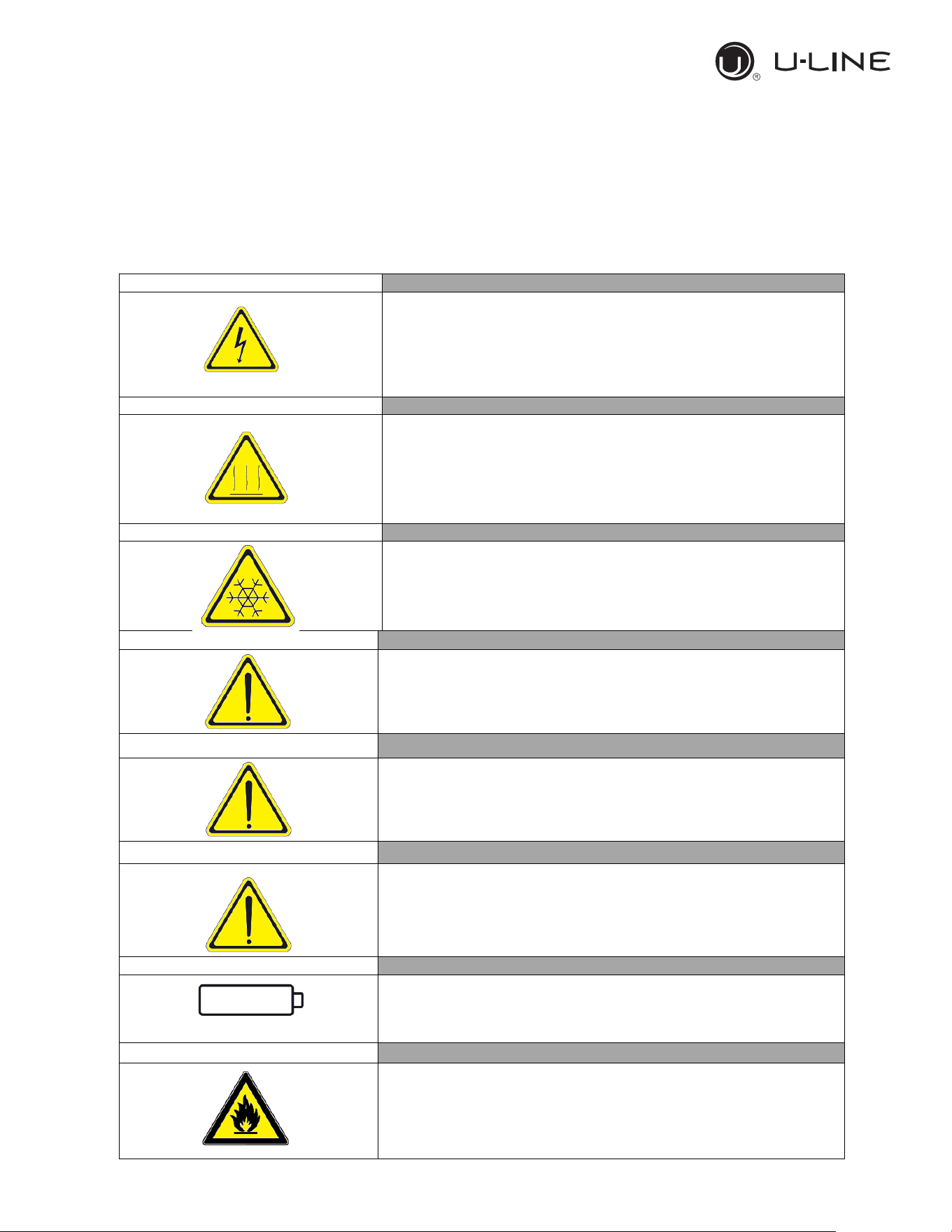
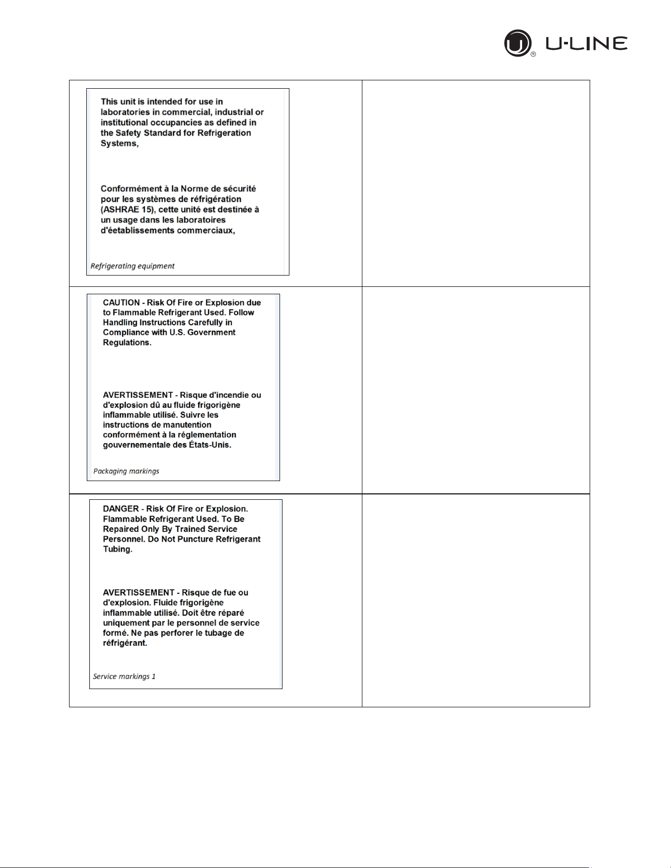
1.11 WARNING LABELS
Electrical Shock
LABEL A
Use of this equipment involves power supplies which convert line
voltage to low voltage power. Do not modify or use power supplies
other than OEM equipment. Connection of the power supply may
require a properly grou
nded receptacle. Potential for electrical
shock or equipment damage exists if precautions are not followed.
Hot Surface
LABEL B
Avoid contact with the hot surfaces potential for skin’s burns.
Cold Surface
LABEL C
Avoid contact with cold freezer surfaces potential for cold burns or
skin sticking to cold surfaces.
Safety Alert
LABEL D
Important operating instructions. To reduce the risk of injury or poor
performance of the unit read the user manual before putting the
equipment into operation
.
Warning
Indicates an immediately hazardous situation, which if not avoided,
will result in death or serious injury
.
Caution
Indicates an immediately hazardous situation, which if not avoided,
may result in minor to moderate injury
Battery
LABEL E
Indicates the location of the back-up battery
Risk of fire
LABEL F
Risk of fire or explosion. Flammable refrigerant used. Follow
handling instruction carefully. To be repaired only by trained service
Personnel. Do not puncture Refrigerant Tubing.
10
Use and Operational Manual
8
OPERATION
Refrigerating Equipment intended for
laboratory use.
Packaging markings
(Label attached upon the cartoon box)
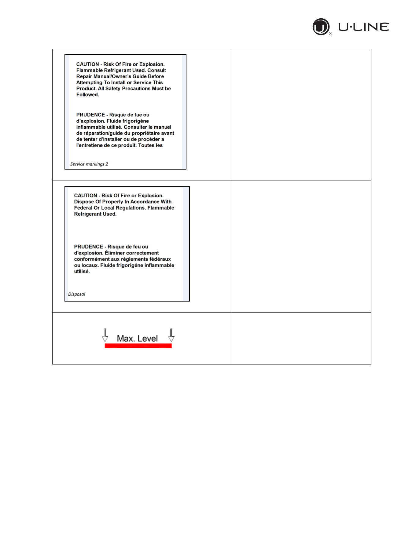
Service markings.
(Label located near the cooling unit compartment)
11
Use and Operational Manual
9
OPERATION
Service markings
(
Label located near the cooling unit compartment)
Disposal
(Marking attached upon the exterior of the
cabinet)
Max high load
12
Use and Operational Manual
10
OPERATION
2. INSTALLATION
2.1 TRANSPORTATION AND HANDLING
The equipment must be transported and handled exclusively in upright position, in
observance of the instructions printed on the packing.
This precaution is necessary to avoid contamination of the refrigerant circuit with compressor lube
oil with resulting valve and heat exchanger coil failure and problems starting the electric motor or
the risk of a gas leak. The manufacturer is not responsible for any problems due to transport
executed in conditions other than those specified herewith.
The equipment is secured to a wooden pallet base, wrapped in a plastic film and packaged into a
three waves carton box..
The equipment must be handled using a fork lift truck or a pallet truck with suitable forks (fork
length at least equal to 2/3 length of unit).
2.2 POSITIONING
Incorrect positioning can cause damage to the equipment and generate hazardous conditions for
personnel. The installer must therefore observe the following general regulations:
Make sure you maintain a minimum of 11,8” (30cm). clearance from the walls and 31,5” (80
cm) from the ceiling. The room must be well ventilated.
Keep well away from sources of heat. Avoid direct sunlight
Remove packing material.
Remove accessories from inside the unit.
Cartoon box or Wood base removal: using a hammer, tilt the cabinet to one side and loosen
the two thread-forming screws, drag the cabinet from the back side holding the base still until
the four castors have gone out from the containing holes, slightly tilt the cabinet backward and
take the base away pulling it from the front side.
Use gloves when handling the 3 Waves cartoon box or the wooden base to protect the hands
from splinters.
Position the equipment with the help of a level. Remove the protective PVC film from the
external surfaces of the unit.
Position the shelf runners in the holes in the uprights. Insert the shelves in the runners.
Note: the shelves included are n.04 of GN2/1 per each door.
The maximum load of each is 48 kg. (30kg for the 12 cu.ft)
2.3 WIRING AND ELECTRICAL HOOK-UP
Receptacle installation and electrical wiring operations must be performed by a qualified
electrician. For safety reasons adhere to the following indications:
Check that the electrical plant is suitably sized for the absorbed power of the unit.
If the electrical socket and the plug on the equipment power cord are incompatible,
call technical service or your local distributor.
The power cord set included with the appliance meets the requirements for use in the
country of purchase. Use the power cord that shipped with the appliance (
Nema 5-15).
If this appliance is to be used in another country, purchase an AC power cord set that
is approved for use in that country
13
Use and Operational Manual
11
OPERATION
The power cord must be rated for the product and for the voltage and current marked
on the product's electrical ratings label. The voltage and current rating of the cord
should be greater than the voltage and current rating marked on the product.
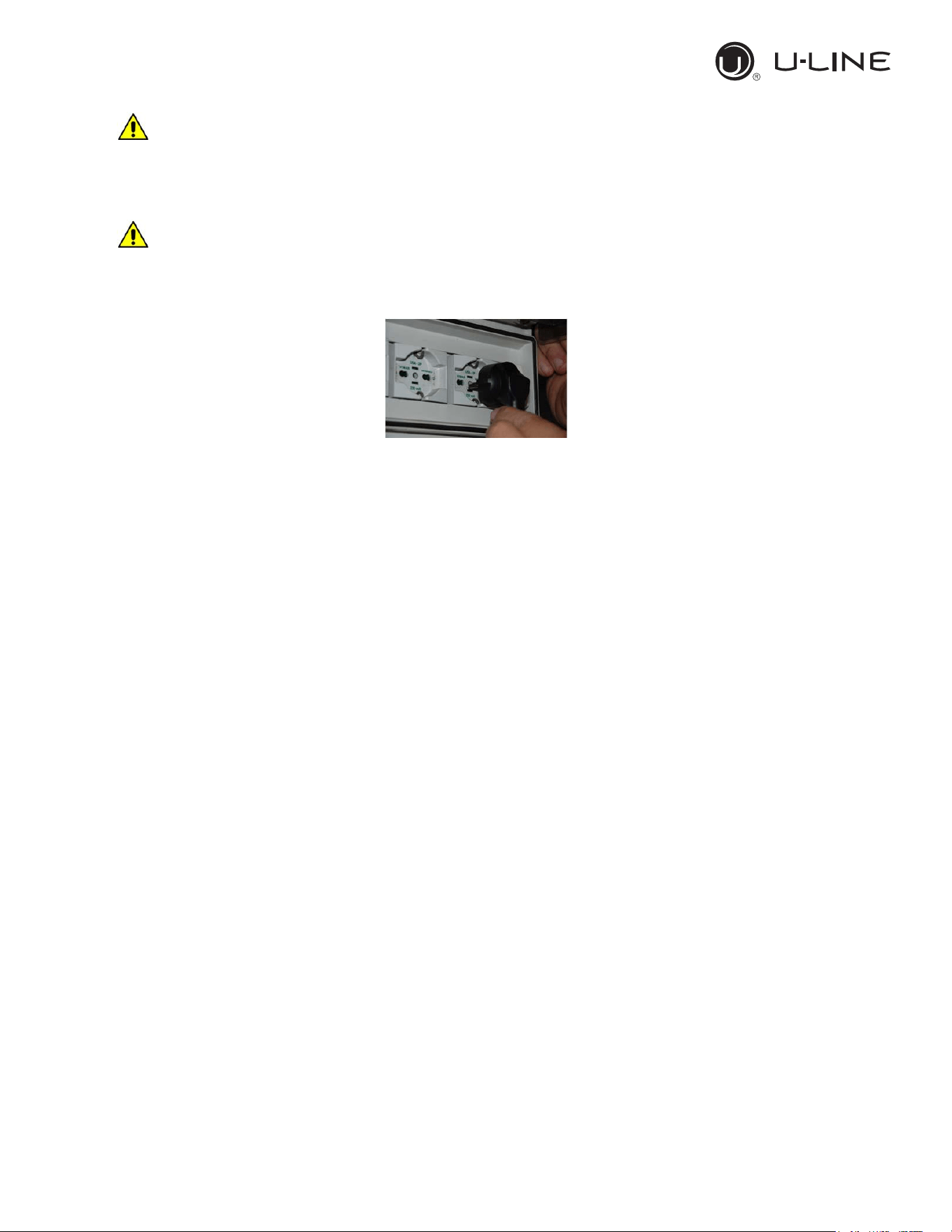
Do not use reductions or multi-way adapters (Fig.1)
It is important to connect the equipment correctly to an efficient earth system
executed in compliance with the relevant legislation.
The equipment must be positioned so that plug can be easily reached (Fig. 1)
Fig. 1
If the SUPPLY CORD is damaged, it must be replaced by the manufacturer, its service agent
or similarly qualified persons in order to avoid a hazard.
2.4 SET UP OPERATIONS
To avoid errors and accidents, perform a series of checks for possible damage sustained during
transport, installation and hook-up operations before starting up the unit.
PRELIMINARY CHECKS
Check the condition of the power cord (no cut or chaffing). Check that the door hinges and
shelf support are stable.
Check the door seals and shelves are not damaged (broken or scratched) and that the door
closes and seals properly.
Make sure all copper tubing, unions are in perfect condition.
FOR OPTIMAL PERFORMANCE
Do not block the motor compartment air vents. Do not lay objects on the top of the equipment
Before storing products wait until they are cold.
Arrange the products on suitable shelves or in containers. Do not place products directly on
the base or against the walls, doors or fixed guards of the unit.
Make sure doors are kept closed.
Keep the defrost water drain outlet clear.
Limit the frequency and duration of opening; each time the door is opened the internal
temperature will alter.
Load products at ambient temperature gradually to allow correct refrigeration. Perform routine
maintenance regularly.
2.5 RE- INSTALLATION
Observe the following procedure:
14
Use and Operational Manual
12
OPERATION
Disconnect the power cord from the electrical outlet.
Handle the equipment in accordance with the instructions in Section 2.1.
Follow the instructions in Section 2.2 for positioning and hook-ups in the new location.
2.6 SCRAPPING AND DISPOSAL
These units may contain materials, which at the end of the working life of the apparatus, must be
disposed at one of the recycling centres nominated by your Local National Health Department or
as specified by the law in force. Scrapping and disposal of the equipment must be carried out in full
observance of established legislation in your country.
In particular, the apparatus may contain the following materials:
Iron
Copper
Aluminium
Non-biodegradable plastics
Fibre glass for printed circuits
Ferrite
Batteries
CFC-free refrigeration gas
Electrical and electronic equipment (WEEE)
The manufacturer shall not be chargeable for any disposal of the apparatus at the end of its
working life.
In line with EU Directive 2002/96/EC for waste electrical and electronic equipment
(WEEE), this electrical product must not be disposed of as unsorted municipal
waste. Please dispose of this product by returning it to your local municipal
collection point for recycling.
15
Use and Operational Manual
13
OPERATION
3. OPERATION
Before switching ON the unit, check that the electrical connections have been made correctly and
above all, that the ground connection is available and working properly.
Please read before using this manual
- This manual is part of the product and should be kept near the instrument for easy and
quick reference.
- Digital controller with defrost and fans management shall not be used for purpose different
from those described hereunder. It cannot be used as a safely device.
- Check the application limits before proceeding.
Safety precautions
- Check the supply voltage is correct before connecting the instrument.
- Do not expose to water or moisture: use the controller only within the operating limits
avoiding the temperature changes with high atmospheric humidity to prevent formation of
condensation.
Warning
- Disconnect all the electrical connections before any kind of maintenance.
- In case of failure or faulty operation contact technical service or Dealer.
- Consider the maximum current which can be applied to each relay.
- Ensure that the wired for probes, loads and the power supply are separated and far enough
from each other, without crossing or intertwining.
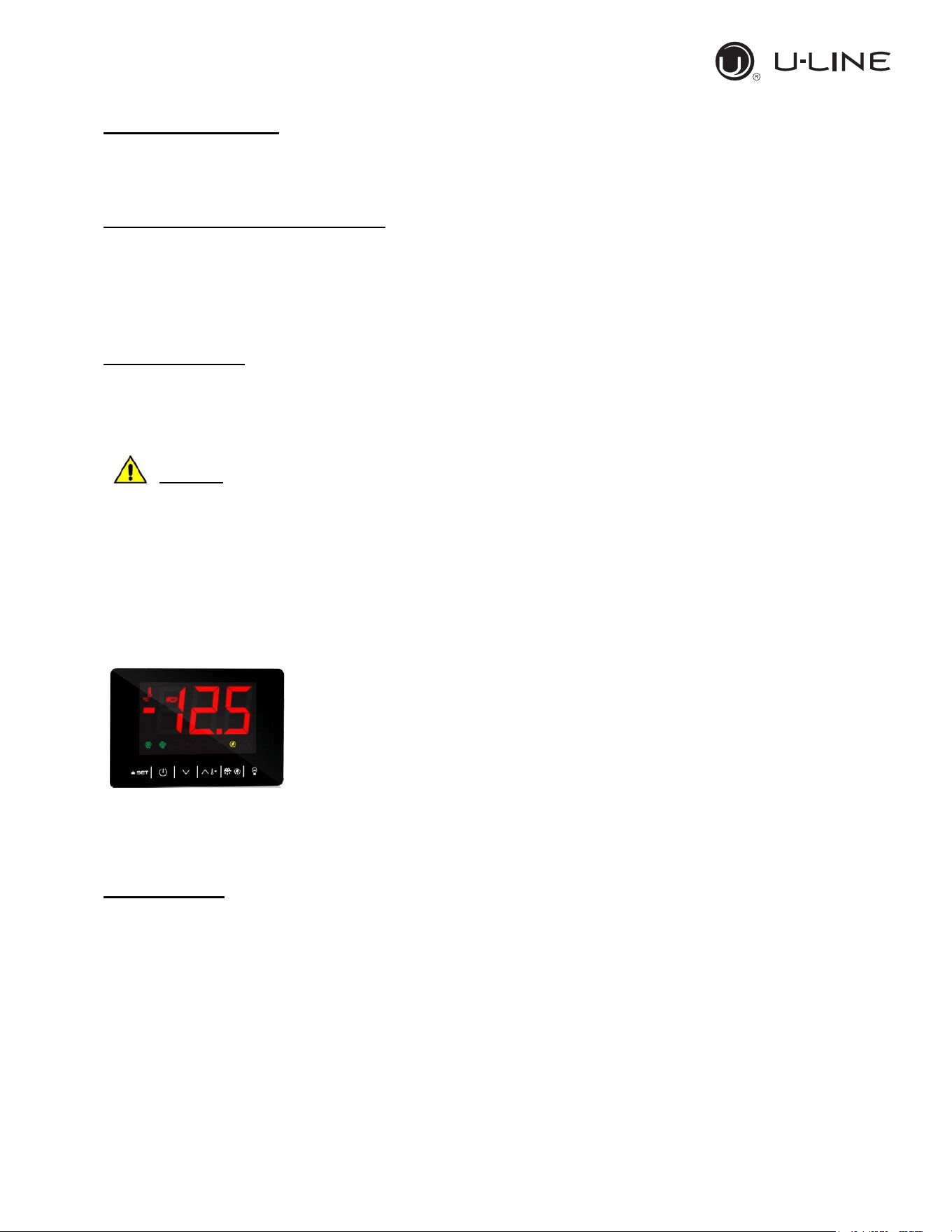
3.1 CONTROLLER GENERAL DESCRIPTION
The controller is a microprocessor based controller suitable for normal
and low temperature air- ventilated application with a membrane
keyboard. The controller has dimensions 101 x 67 x 47 mm, while the
keyboard has dimensions 200 x 82 millimeters, six electro-mechanical
relays.
The controller is also provided with 2 probe inputs either NTC or PTC
type: the probe “Pb1” defined as “Control probe” and used for the
compressor activation, the “Pb2” defined as “Evaporator probe” and used to control the evaporator
fan operation and the defrost cycle; The device has also an additional input configurable as
analogue input (“Auxiliary probe” Pb3) or digital input (“Door switch/multi-function input”)
Technical Data
Heat and fire resistance category: D.
Connections: Removable screw terminal blocks for wires up to 2,5 mm
2
; Micro-MaTch
connectors; Pico-blade connectors.
Maximum length allowed to the connection cables: 10 meters (32,8ft) for power supply cord;
10 meters (32,8ft) for Analogue inputs; 10 meters (32,8ft) for Digital inputs; 10 meters (32,8ft) for
Digital outputs.
Operating temperature: from -5°C to 55°C (from 23 to 131°F)
Operating humidity: Relative humidity without condensate from 10 to 90%.
Pollution status of the device: 2.
16
Use and Operational Manual
14
OPERATION
Power supply: 12 VAC (+10% -15%) 50/60Hz (±3Hz) max 4VA insulated - 12VDC max 3,5W
Over voltage category: III.
Analogue input: 2 for NTC/PTC nodes (Cabinet probe and Evaporator probe)
Sensor range:
-PTC: from -50°C to 150°C (from -58 to 302°F)
-NTC: from -40°C to 105°C (from -40 to 221°F)
Sensitivity: 0,1°C (1°F)
Digital inputs: 1 (microport) for NO/NC contac (dry contact: 5VDC, 2mA)
Digital outputs: 6 electro-mechanical relays
Relay K1: SPST, 16A res. @250VCA
Relay K2: SPDT, 8A res @250VCA
Relay K3: SPST, 16A res @250VCA
Relay K4: SPST, 8A res @250VCA
Relay K5: SPST, 5A res @250VCA
Relay K6: SPDT, 8A res @250VCA
Alarm buzzer: Incorporated.
The maximum current applicable to the loads is 24A
.
Communication port: 1 TTL MODBUS slave port for EVconnect APP or BMS (by request)
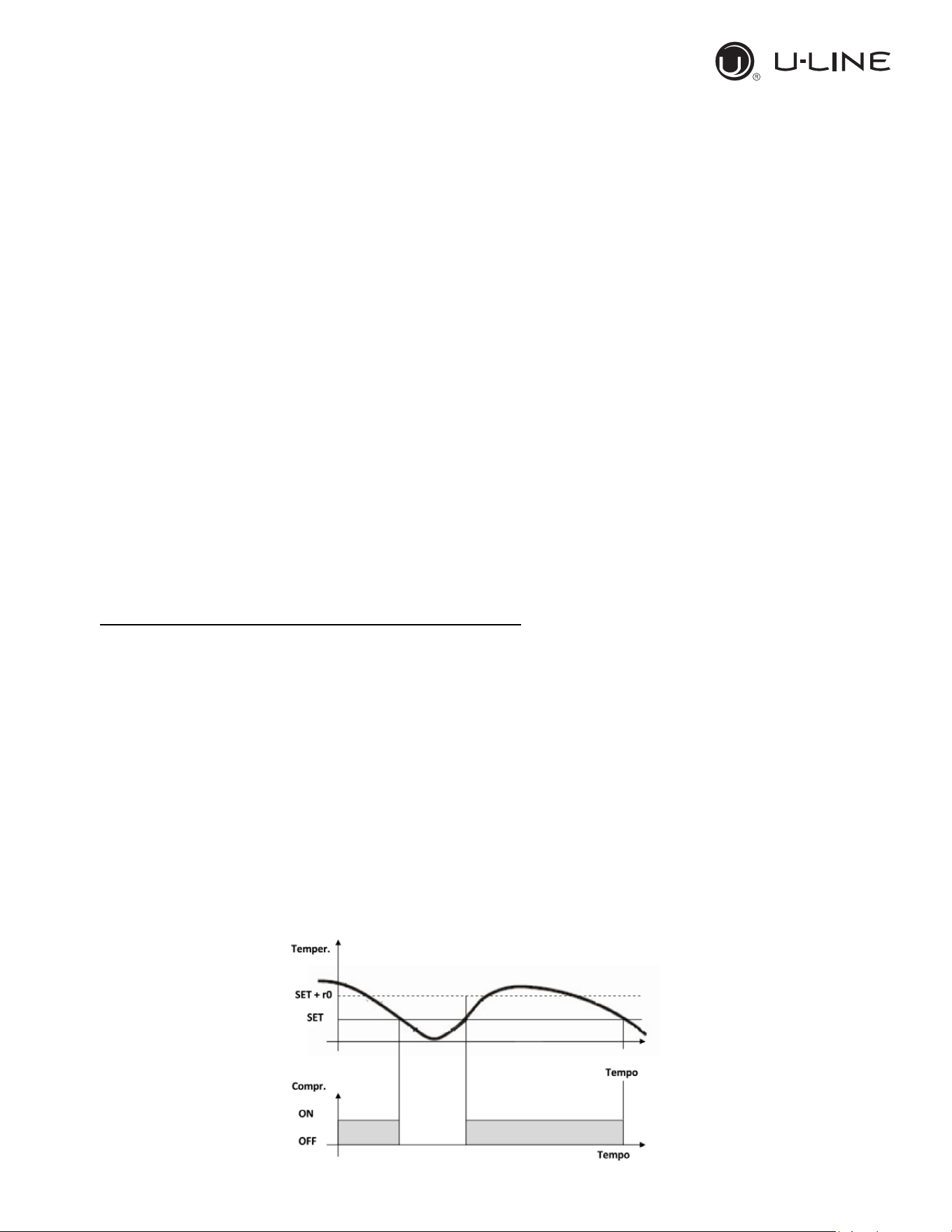
3.2 REGULATION
Once set a desired temperature required for the products storage within the operational range of
each models, the regulation of the cooling system is controlled by the temperature measured by
the control probe with a positive differential from the set point: when the temperature rises up to the
set point plus differential the compressor starts to pull down the temperature and it turns off when
the desired set point is reached again.
In case of faulty probe the compressor activation is timed through the parameter “C4” and “C5”
17
Use and Operational Manual
15
OPERATION
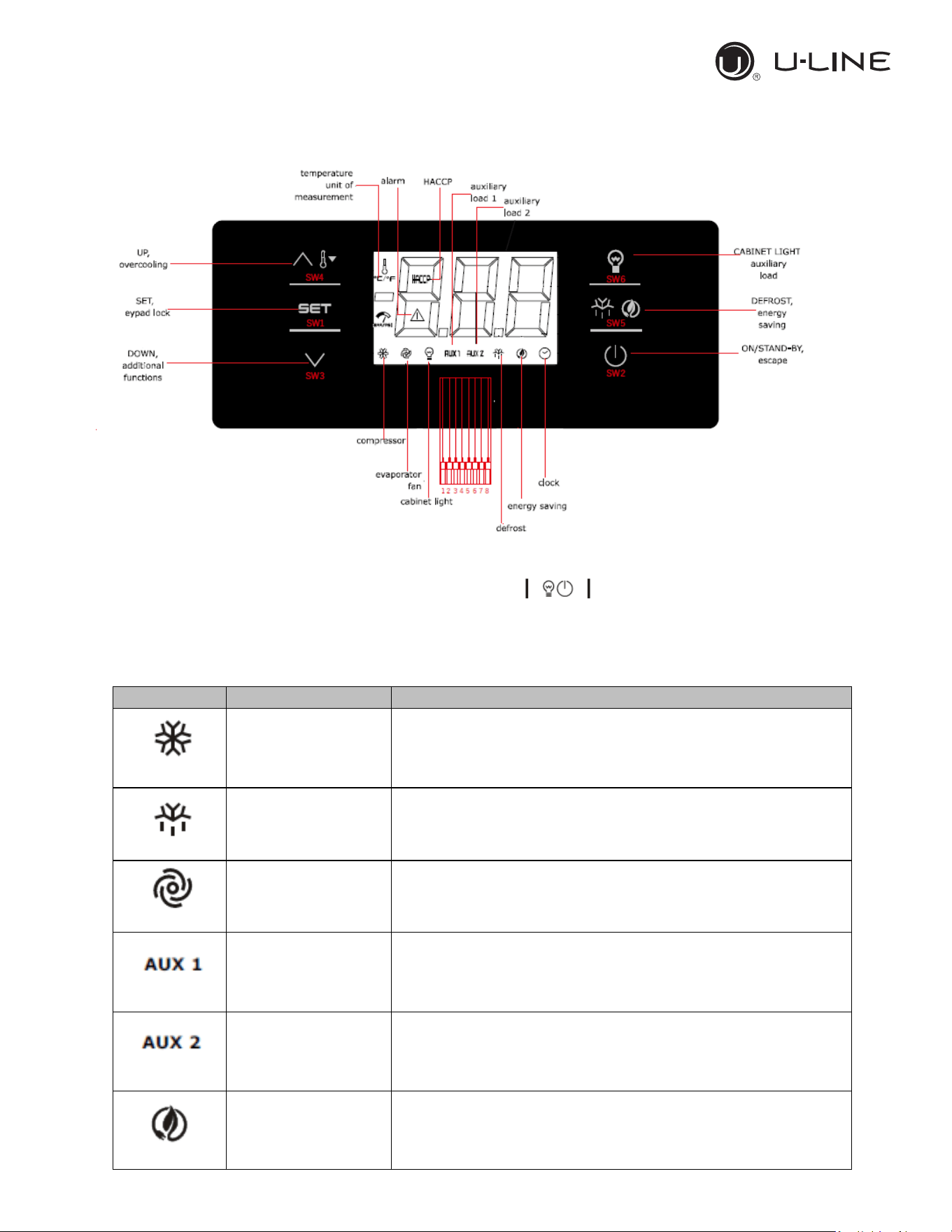
3.3 CONTROLLER KEYBOARD AND MAIN FUNCTION
3.3.1 Switching the device ON/OFF
If the parameter POF=1,touch the ON/STAND-BY key and hold it for 2 sec. Once the
device is switched on the display will show temperature value according with the parameter P5.
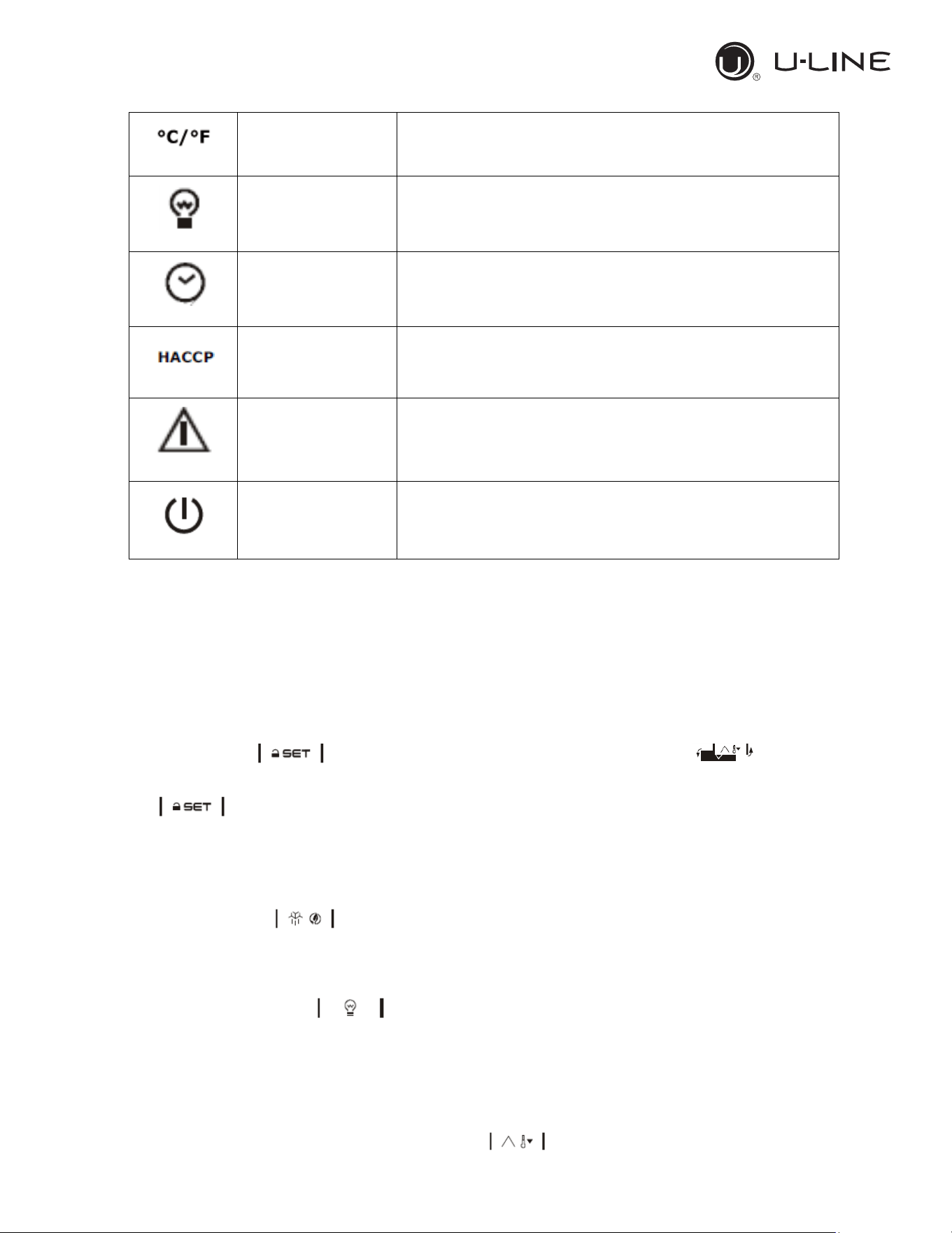
3.3.2 Use of LEDs
LED
MODE
MEANING
-ON
-OFF
-Flashing
-Compressor ON
-Compressor OFF
-Compressor protection activated/set point temperature
menu
-ON
-OFF
-Flashing
- Active Defrost/ pre-dripping cycle
-No action.
-Defrost delay time/ dripping cycle active
-ON
-OFF
-Flashing
-Evaporator fan ON
-Evaporator fan OFF
-Evaporator fan stop
-ON
-OFF
-Flashing
-Auxiliary function 1 ON
-Auxiliary function 1 OFF
-Auxiliary function 1ON by digital input/ Auxiliary function 1
delay active
-ON
-OFF
-Flashing
-Auxiliary function 2 ON
-Auxiliary function 2 OFF
-Auxiliary function 2 ON by digital input/ Auxiliary function
2 delay active
-ON
-OFF
-Flashing
-Active Energy saving mode
-no action
-no action
18
Use and Operational Manual
16
OPERATION
-ON
-OFF
-Flashing
-Normal temperature view
-no action
-Active overheating/overcooling cycle
-ON
-OFF
-Flashing
-Cabinet light ON
-Cabinet light OFF
-Cabinet light ON by digital input
-ON
-OFF
-Flashing
-view time
-no action
-set date, time and day of the current week
-ON
-OFF
-Flashing
-Saved HACCP alarm
-no action
-new HACCP alarm saved
-ON
-OFF
-Flashing
-Alarm active
-no action
-no action
-ON
-OFF
-Flashing
-Device OFF
-Device ON
-Device ON/OFF mode
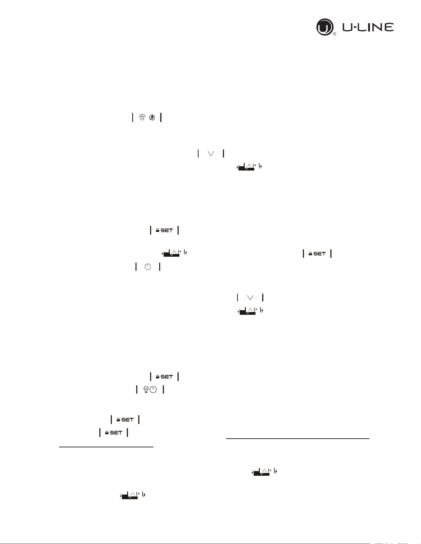
3.3.3 Keypad unlocking
If the parameter Loc=1 (default) after 30 sec without any keys of the display has been pressed, the
display will show the label “Loc” and the keypad will lock automatically.
To unlock the keypad, touch a key for 1 sec: the display will show the label “UnL”.
3.3.4 Operational temperature settings
If the keypad is locked, firstly unlock it.
Touch the SET key then set the desired temperature by pressing the
Up or DOWN key within 15s according with the limits range of the set point (parameters r1 and r2).
Press to confirm or do not operate for 15 sec.
3.3.5 Manual defrost
Firstly check the keypad is not locked (and in case unlock it) and the overcooling cycle is not
activated.
Touch the Defrost key holding it for 2 sec. If the parameter P3=1 and the evaporator
temperature value is lower than the parameter d2, the defrost cycle will start.
3.3.6 Cabinet light ON/OFF (if the parameter u1=0)
Touch the Cabinet light key
3.3.7 Buzzer
If the parameters u1=3 and u4=1 touch any key to shut down the buzzer alarm.
3.3.8 Overcooling/overheating cycle activation and Manual energy saving
Check the keypad is unlock then press DOWN key :
19
Use and Operational Manual
17
OPERATION
• If the parameter r5=0 and the defrost cycle is not activated the Overcooling cycle will start:
the cooling unit runs a cycle with a set point of r6 parameter for the time r7.
• If the parameter r5=1 the unit will perform an Overheating cycle having a operational
temperature of “setpoint+r6” for a time fo r7.
3.3.9 Activate/deactivate energy saving in manual mode (if r5 = 0)
Check that the keyboard is unlock.
Touch the DEFROST key , the setpoint becomes “setpoint+r4” for a max duration of HE2.
3.3.10 Displaying/reset the compressor operational time
Check the keypad is unlocked then press the DOWN key for 2 sec.
Scroll through the menu’s labels by the UP or DOWN key :
• CH1 label: displaying compressor operating hours.
• CH2 label: displaying second compressor operating hours
• rCH label: compressor operating hours reset.
• nS1 label: compressor star-up time.
To access the label press SET .
In order to reset the compressor operating hours once selected the rCH label, insert the password
“149”using the UP or DOWN keys then confirm touching the SET key
Touch the ON/STAND-BY key to exit the procedure or do not operate for 60 sec.
3.3.11 Displaying temperature probes
Ensure the keypad is unlocked then touch the DOWN key for 2 sec.
Scroll through the menu’s labels by the Up or DOWN key :
• Pb1: cabinet temperature probe (if parameter P4=0,1 or 2); inlet air temperature probe (if
parameter P4=3).
• Pb2: Evaporator temperature probe (if parameter P3=1 or 2)
• Pb3: Auxiliary temperature probe (If P4=1, 2 or 3).
• Pb4: Calculated product temperature (CPT; P4=3)
To access the label press SET .
Touch the ON/STAND-BY key to exit the procedure or do not operate for 60 sec.
3.3.12 Setting operational parameters
Touch the SET key for 4 sec, the monitor will display the label “PA”.
Press SET key and insert the password that will be provided only by the manufacturer or
the authorized service agent.
Press SET key to confirm.
Scroll through the parameters list using the UP or DOWN key .
For modifying a parameter value, press SET key at the parameter label then adjust the value by
the UP or DOWN key .
Press SET key to confirm the changing.
20
Use and Operational Manual
18
OPERATION
Press SET key for 4 sec or do not operate for 60 sec to exit the procedure.
Do not change any parameters without the authorization of the manufacturer or any
authorized service agency indeed this may cause a malfunction of the application and may
involve in the lost of warranty.
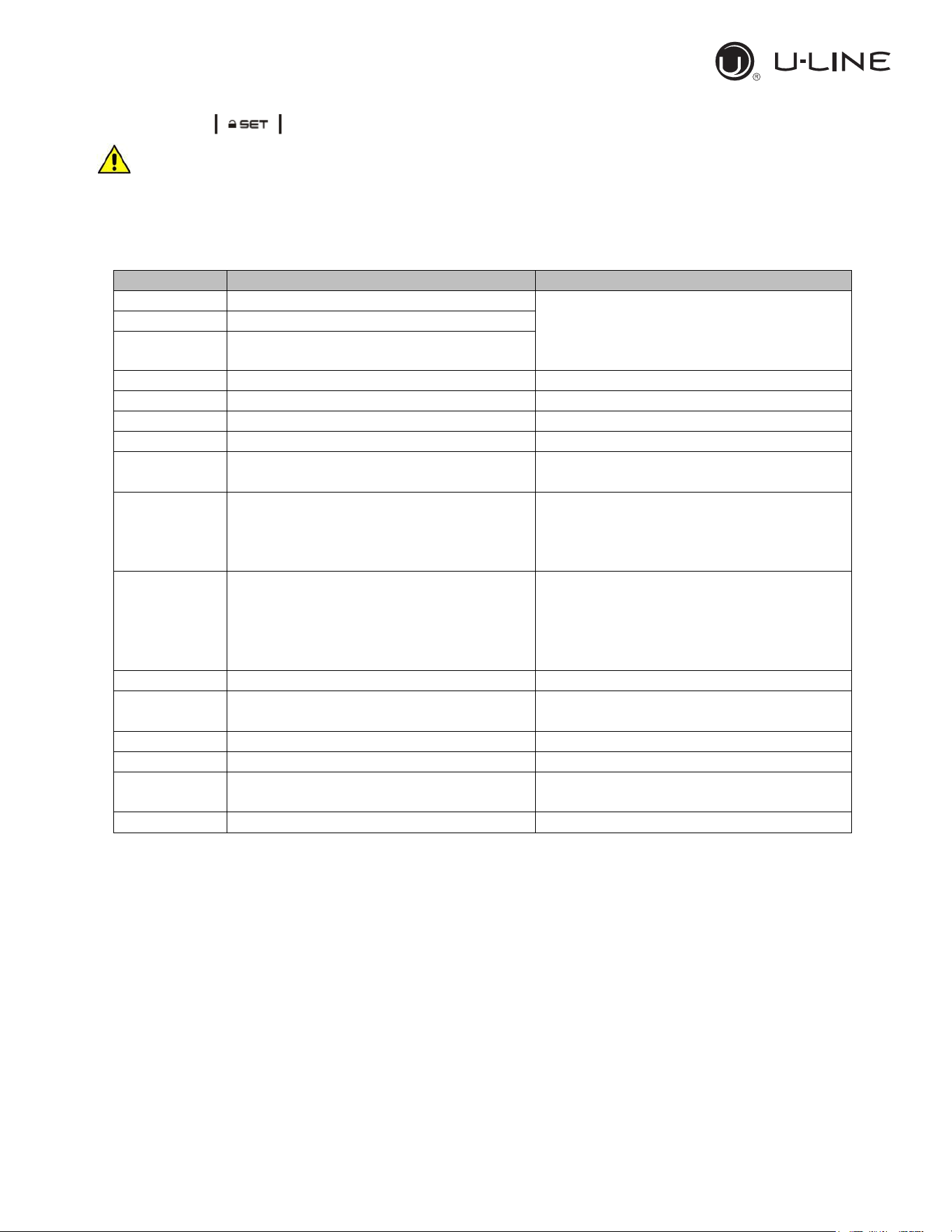
3.3.13 Alarms
Alarm code
Code description
Solution
Pr1
Cabinet probe alarm
-Check the parameter P0.
-Check the status of the probe.
-Check the electrical connection.
-Replace the probe.
Pr2
Evaporator probe alarm
Pr3
Auxiliary probe alarm
rtc
Date and time alarm
Set date, time and day of the week.
AL
Low Temperature Alarm
Check the parameters AA, A1 and A2
AH
High Temperature Alarm
Check the parameter AA, A4 and A5
id
Door open alarm
Check the parameter i0 and i1
PF
Power failure alarm
-Check electrical connection
-Touch any key to shut the buzzer off
COH
High condenser warning
-Check if the condenser probe is
installed.
-Check the parameter C6
-Check the condenser coil is clean.
CSd
High condensation alarm
Check if the condenser probe is
installed.
-Check the parameter C7.
-Check the condenser coil is clean.
-Reboot the device.
iA
Multi-function input alarm
-Check the parameters i5 and i6
iSd
High pressure alarm
-Swich the device off and on
-Check the parameters i5, i6, i8, i9
LP
Low pressure alarm
-Check the parameter i5, i6
C1t
Compressor thermal switch alarm
-Check the parameter i5, i6
C2t
Second compressor thermal switch
alarm
-Check the parameter i5, i6
dFd
Defrost time out alarm
-Check the parameters d2, d3 and d11
21
Use and Operational Manual
19
OPERATION
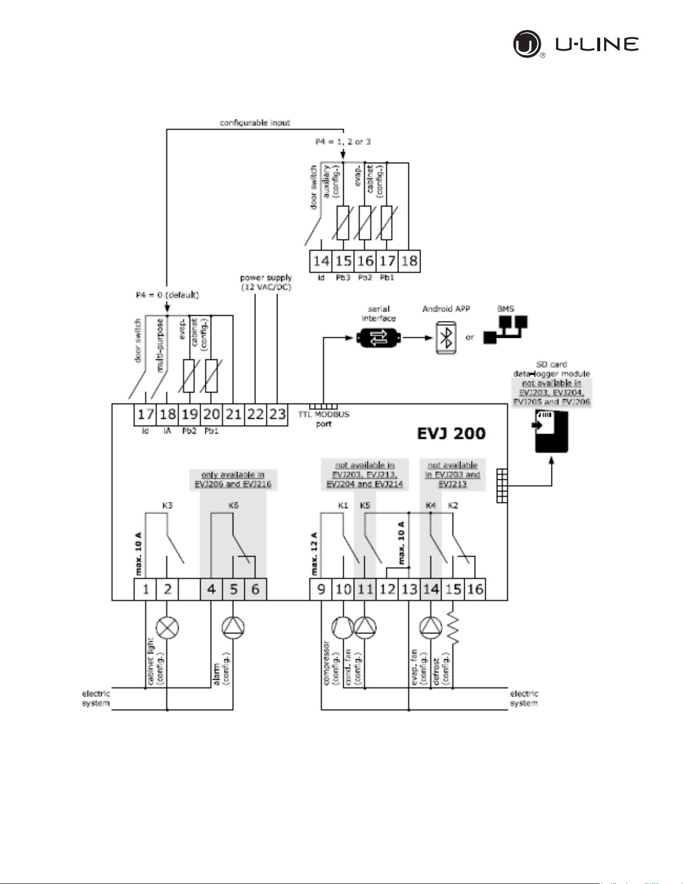
3.3.14 Electrical connection
22
Use and Operational Manual
20
OPERATION
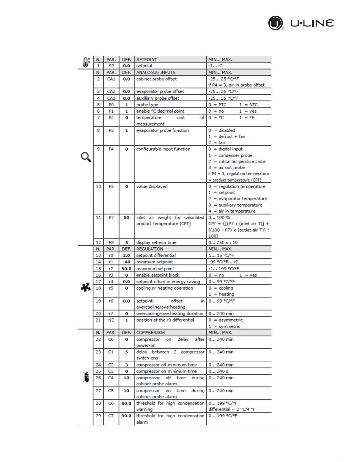
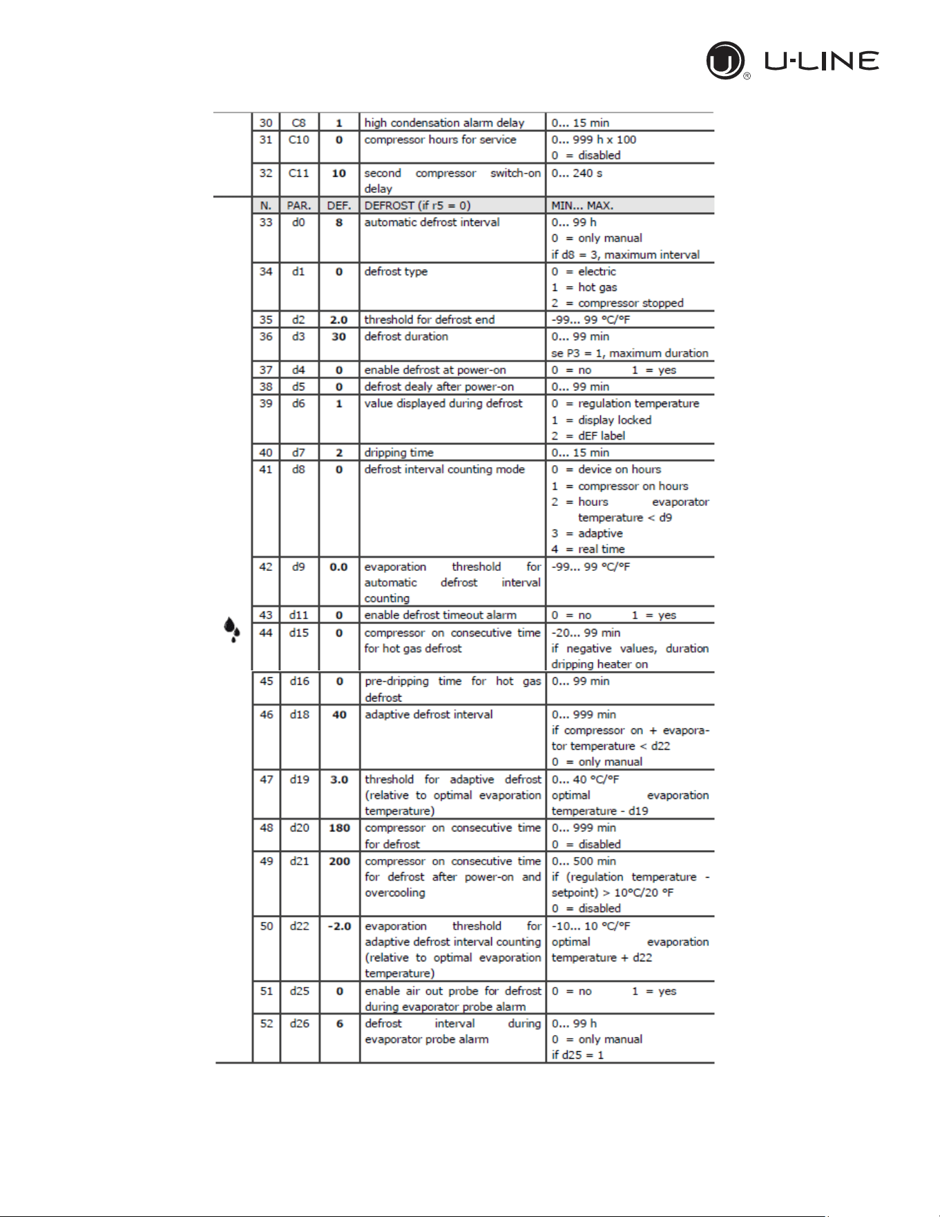
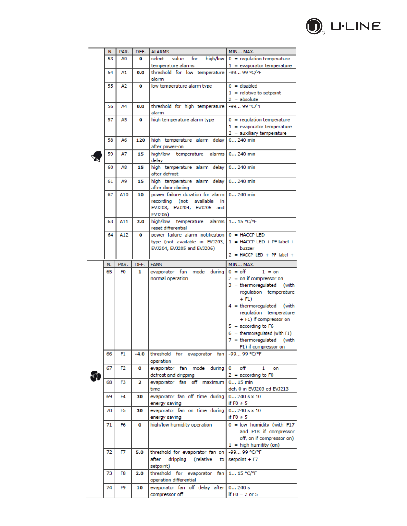
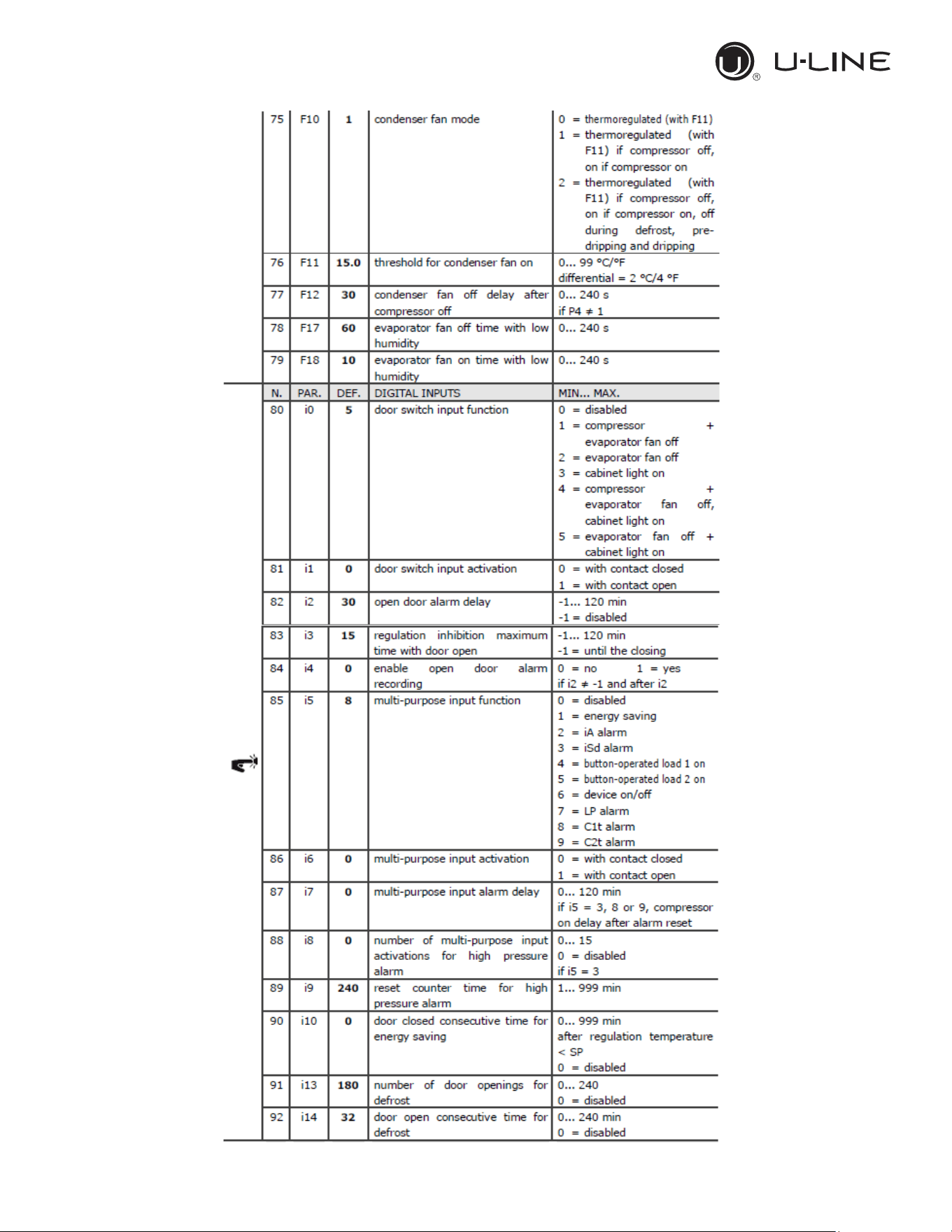
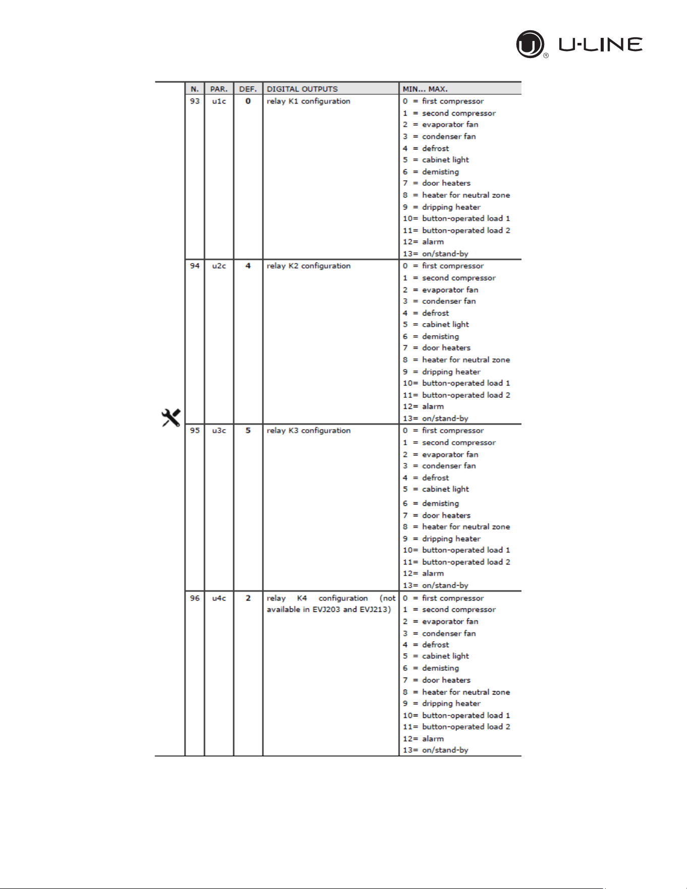
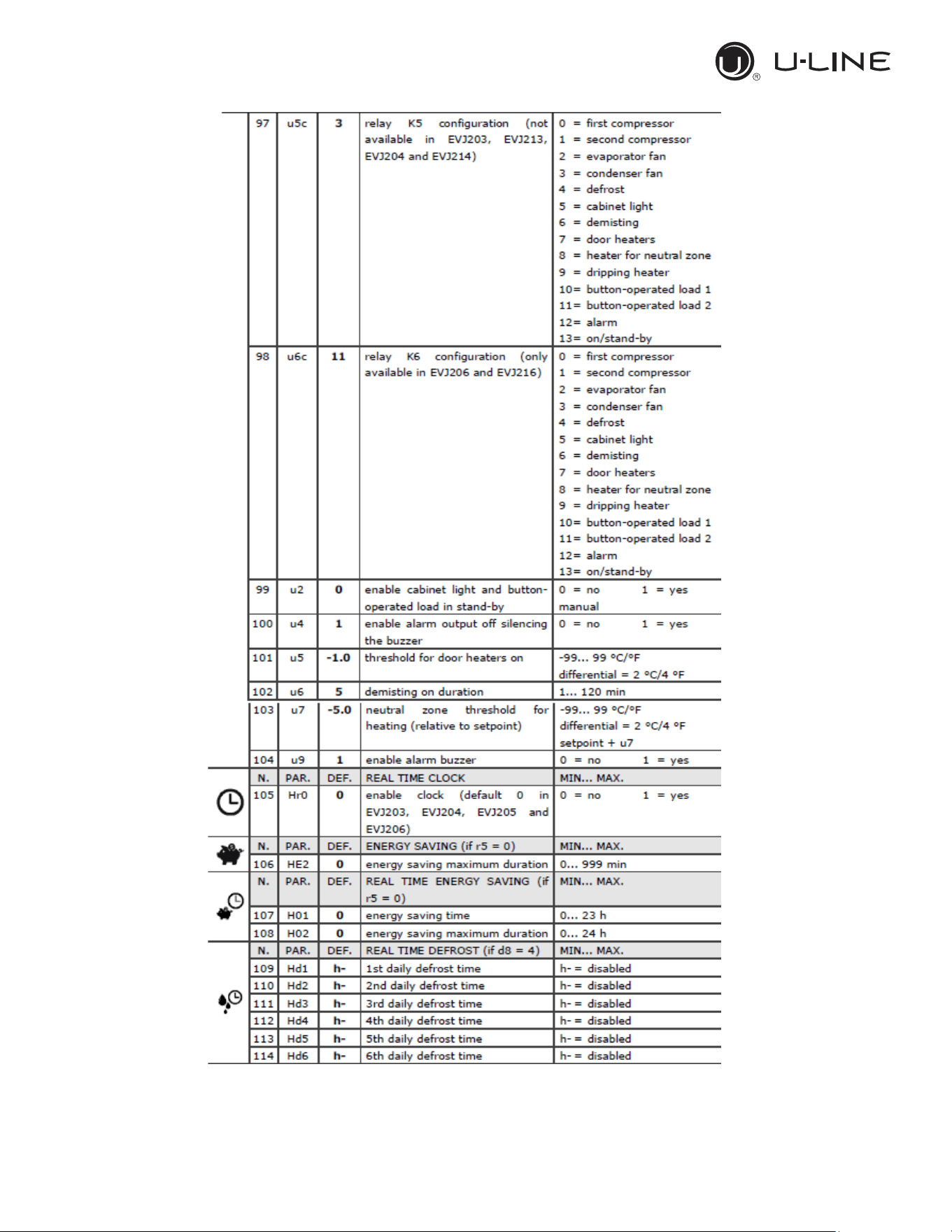
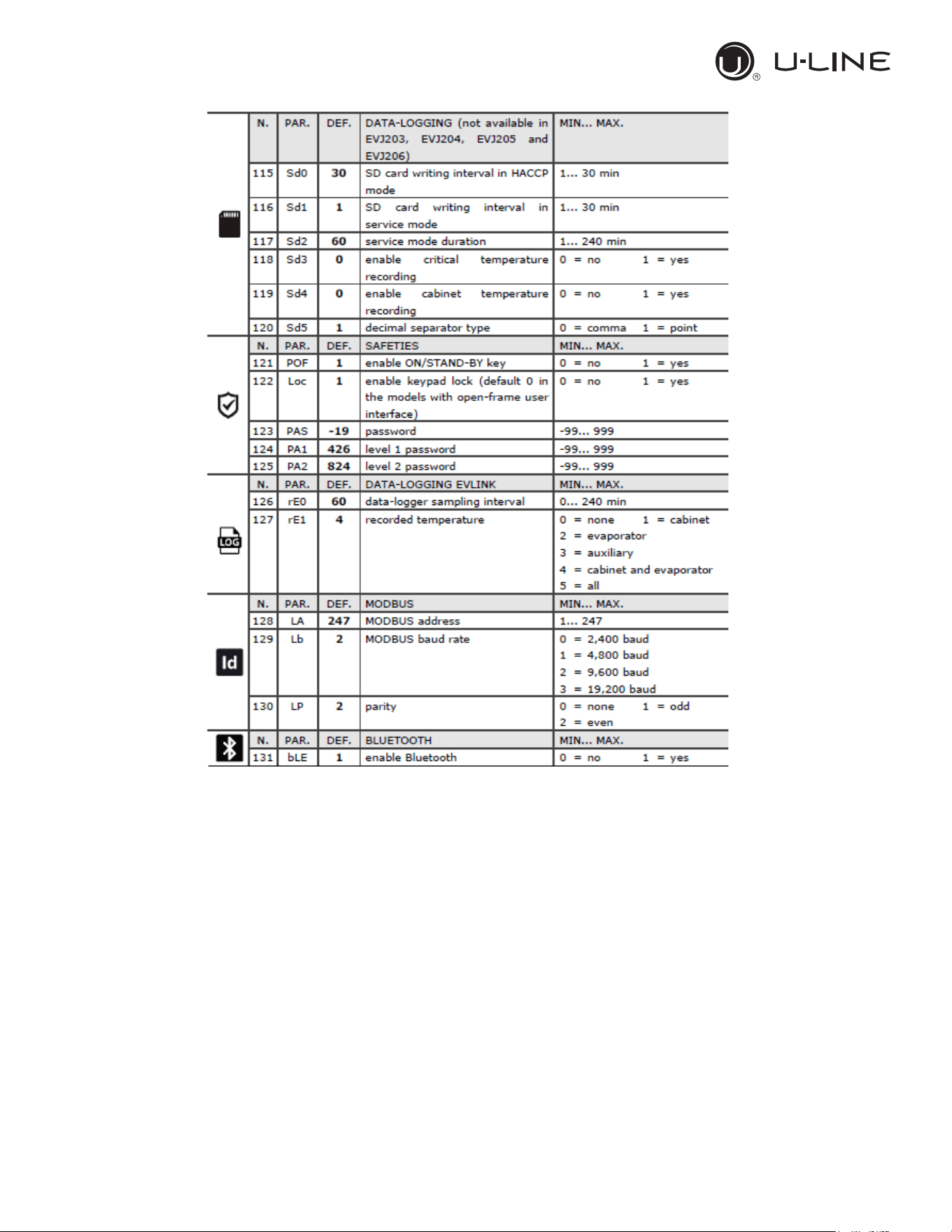
3.3.15 Default parameters value and description
23
Use and Operational Manual
21
OPERATION
24
Use and Operational Manual
22
OPERATION
23
OPERATION
26
Use and Operational Manual
24
OPERATION
27
Use and Operational Manual
25
OPERATION
28
Use and Operational Manual
26
OPERATION
3.3.16 EPOCA CLOUD SOLUTIONS
As a standard the controller is equipped with a Wi-fi
dongle for connecting the unit to a cloud. The EVlink
wi-fi is based on TLS technology and uses TCP8883
port.
START UP
In order to setup the Wifi module, this method of
connection is suitable with any kind of PCs or smart
portable devices such as phone or tablets, no matter
which operative system is installed.
29
Use and Operational Manual
27
4. MAINTENANCE AND REPAIR
Maintenance and repair must be carried out by qualified personnel authorized by the manufacturer.
The manufacturer declines any responsibility for jobs carried out by unauthorized
personnel or the use of non-original spare parts.
4.1 ROUTINE MAINTENANCE
Prohibited to remove the guards and safety devices: It’s strictly forbidden to remove
guards or safety devices when performing routine maintenance operation. The manufacturer
disclaims all liability that may arise this regulation is not observed.
In case of FIRE
:
- Disconnect the unit from the electrical power socket.
- Do not use water to extinguish the fire.
- Use powder or foam extinguishers.
4.1.1 Cleaning the interior and exterior of the appliance
The appliance is designed for the products storage so it is important to keep it clean. The
equipment is thoroughly cleaned at the factory before being shipped. We recommend, however, to
clean the interior cabinet before the first start up of the appliance. Before attempt any cleaning
operation make sure the power cord is disconnected.
-Cleaning product: use soft clean cloth wet with water and neutral detergent only.Do not use
solvent or bleach.
-Rinsing: use a cloth or sponge soaked with fresh clean water. Do not use water jet.
-Frequency: once a week or at different intervals in accordance with the type of product.
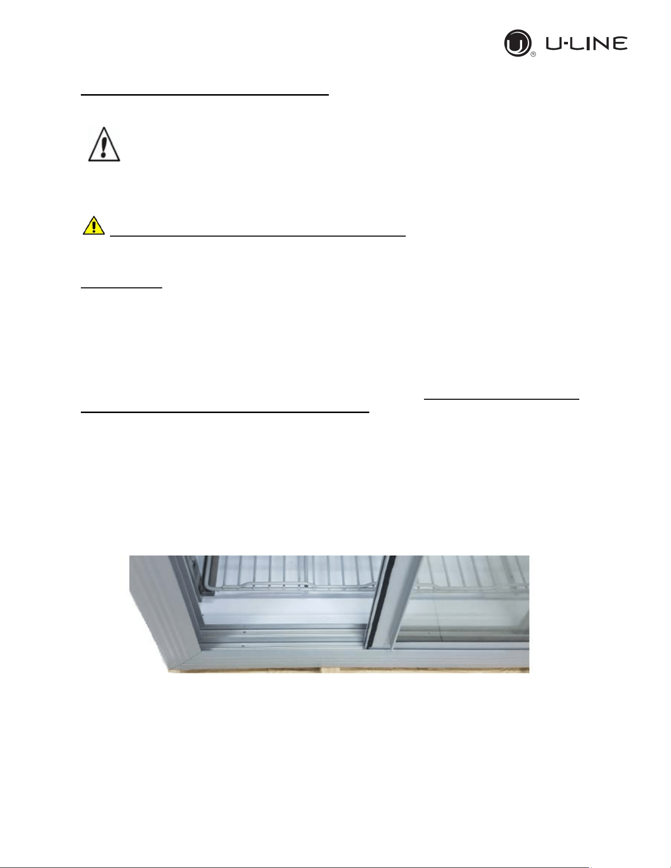
4.1.2 Sliding door’s rails cleaning.
Keep clean the sliding door housing to avoid the door can’t close completely. Use a soft clean cloth
or a soft brush in order to remove any residuals can block the door to slide in the full closure
position.
4.1.3 Condenser cleaning
The condenser is a heat exchanger. If it is dirty or clogged the air cannot circulate freely through
the same, it cannot discharge heat properly so reducing proportionally the performance and the
efficiency of the refrigeration system.
FOR THOSE REASONS IT IS IMPORTANT TO KEEP CLEAN THE CONDENSER COIL,
TYPICALLY MONTHLY.
Use and Operational Manual
28
Always switch off the unit and disconnect power cord before cleaning, it is dangerous
to do it with power ON: fan may start suddenly at any time.
Use a convenient ladder to reach the condenser. Use an air jet or vacuum with a soft dry brush if
necessary and remove any dust or fluff from the heat exchanger fins.
After cleaning, start the equipment.
During the cleaning operation wear gloves and safety glasses to protect yourself from any
injury
5. TROUBLESHOOTING
The Chart shows the most frequent breakdowns , possible causes and relative remedies:
PROBLEM DESCRIPTION POSSIBLE CAUSE SOLUTION
The appliance does not come on
The main switch is "off"
There is no tension
Other
Main switch “on”
Check plug, socket, electric connection
Contact technical assistance
The refrigerator unit does not start
Set temperature is reached
Defrosting is in operation
Control Panel is broken
Other
Set new temperature
Wait for end of cycle, switch off and switch back
on
Contact technical assistance
Contact technical assistance
The refrigerator is continuously
working but does not reach the set
temperature
Room is too hot
Condenser is dirty
Refrigerant fluid is insufficient
Condenser fan has stopped
Door not properly closed
Evaporator is frosted up
Defrost valve is open
Air better
Clean condenser
Contact technical assistance
Contact technical assistance
Check door seals
Manual defrosting
Contact technical assistance
Refrigerator does not stop at set
temperature
Control Panel is broken
Temperature probe is broken
Door is not airtight
Contact technical assistance
Contact technical assistance
Close door
Ice blocks on evaporator
Improper use
Control Panel is broken
Contact technical assistance
Contact technical assistance
Appliance is noisy
Appliance not levelled
Contact with external bodies
Screws or nuts loose
Other
Check that appliance is level.
Check that no tube
or ventilator fan is in contact
with external bodies.
Tighten
Contact technical assistance
Safety DC fan does not work
Fan disconnected
Stuck fan
Fan motor damaged
Re-wire the fan to the electrical strip contact
Replace the fan
Replace the fan
37
Use and Operational Manual
29
