
HL 6
LINE ARRAY MODULE
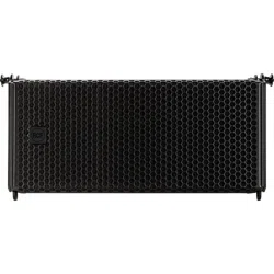
HL 35
FLYABLE SUBWOOFER
OWNER’S MANUAL
MANUALE UTENTE


3
CONTENTS
ENGLISH
1 SAFETY PRECAUTIONS AND GENERAL INFORMATION ................................................................................................................. 4
2 DESCRIPTION .................................................................................................................................................................................... 6
3 REAR PANEL ...................................................................................................................................................................................... 7
4 RIGGING THE SYSTEM ...................................................................................................................................................................... 8
5 INSTALLATION .................................................................................................................................................................... 16
6 TRANSPORTATION ..............................................................................................................................................................27
ITALIANO
1 AVVERTENZE PER LA SICUREZZA E INFORMAZIONI GENERALI ................................................................................................. 28
2 DESCRIZIONE .................................................................................................................................................................................. 30
3 PANNELLO POSTERIORE ................................................................................................................................................................. 31
4 APPENDIMENTO DEL SISTEMA ..................................................................................................................................................... 32
5 INSTALLAZIONE .................................................................................................................................................................49
6 TRASPORTO ........................................................................................................................................................................19
HL 6 DIMENSION2 .......................................................................................................................................................................52
HL 35-S DIMENSION2 ..................................................................................................................................................................53
SPECIFICATION ............................................................................................................................................................................54
4
EN
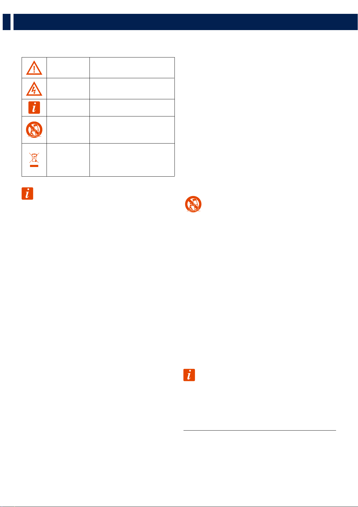
1. SAFETY PRECAUTIONS AND GENERAL INFORMATION
The symbols used in this document give notice of important operating instructions
and warnings which must be strictly followed.
CAUTION
Important operating instructions:
explains hazards that could damage a
product, including data loss
WARNING
Important advice concerning the use of
dangerous voltages and the potential
risk of electric shock, personal injury or
death.
IMPORTANT NOTES
Helpful and relevant information
about the topic
SUPPORTS, TROLLEYS
AND CARTS
Information about the use of supports,
trolleys and carts. Reminds to move with
extreme caution and never tilt.
WASTE DISPOSAL
This symbol indicates that this product
should not be disposed with your
household waste, according to the
WEEE directive (2012/19/EU) and your
national law.
IMPORTANT NOTES
This manual contains important information about the correct and safe use of the
device. Before connecting and using this product, please read this instruction manual
carefully and keep it on hand for future reference. The manual is to be considered
an integral part of this product and must accompany it when it changes ownership
as a reference for correct installation and use as well as for the safety precautions.
RCF S.p.A. will not assume any responsibility for the incorrect installation and / or
use of this product.
SAFETY PRECAUTIONS
1. All the precautions, in particular the safety ones, must be read with special
attention, as they provide important information.
2. Power supply from mains
a. The mains voltage is sufficiently high to involve a risk of electrocution; install
and connect this product before plugging it in.
b. Before powering up, make sure that all the connections have been made
correctly and the voltage of your mains corresponds to the voltage shown on
the rating plate on the unit, if not, please contact your RCF dealer.
c. The metallic parts of the unit are earthed through the power cable. An apparatus
with CLASS I construction shall be connected to a mains socket outlet with a
protective earthing connection.
d. Protect the power cable from damage; make sure it is positioned in a way that
it cannot be stepped on or crushed by objects.
e. To prevent the risk of electric shock, never open this product: there are no parts
inside that the user needs to access.
f. Be careful: in the case of a product supplied by manufacturer only with
POWERCON connectors and without a power cord, jointly to POWERCON
connectors type NAC3FCA (power-in) and NAC3FCB (power-out), the following
power cords compliant to national standard shall be used:
- EU: cord type H05VV-F 3G 3x2.5 mm2 - Standard IEC 60227-1
- JP: cord type VCTF 3x2 mm2; 15Amp/120V~ - Standard JIS C3306
- US: cord type SJT/SJTO 3x14 AWG; 15Amp/125V~ - Standard ANSI/UL 62
3. Make sure that no objects or liquids can get into this product, as this may cause
a short circuit. This apparatus shall not be exposed to dripping or splashing. No
objects filled with liquid, such as vases, shall be placed on this apparatus. No naked
sources (such as lighted candles) should be placed on this apparatus.
4. Never attempt to carry out any operations, modifications or repairs that are not
expressly described in this manual.
Contact your authorized service centre or qualified personnel should any of the
following occur:
- The product does not function (or functions in an anomalous way).
- The power cable has been damaged.
- Objects or liquids have got in the unit.
- The product has been subject to a heavy impact.
5. If this product is not used for a long period, disconnect the power cable.
6. If this product begins emitting any strange odours or smoke, switch it off
immediately and disconnect the power cable.
7. Do not connect this product to any equipment or accessories not foreseen.
For suspended installation, only use the dedicated anchoring points and do not try
to hang this product by using elements that are unsuitable or not specific for this
purpose. Also check the suitability of the support surface to which the product is
anchored (wall, ceiling, structure, etc.), and the components used for attachment
(screw anchors, screws, brackets not supplied by RCF etc.), which must guarantee
the security of the system / installation over time, also considering, for example, the
mechanical vibrations normally generated by transducers.
To prevent the risk of falling equipment, do not stack multiple units of this product
unless this possibility is specified in the user manual.
8. RCF S.p.A. strongly recommends this product is only installed by
professional qualified installers (or specialised firms) who can ensure
correct installation and certify it according to the regulations in force.
The entire audio system must comply with the current standards and
regulations regarding electrical systems.
9. Supports, trolleys and carts.
The equipment should be only used on supports, trolleys and carts,
where necessary, that are recommended by the manufacturer. The
equipment / support / trolley / cart assembly must be moved with
extreme caution. Sudden stops, excessive pushing force and uneven
floors may cause the assembly to overturn. Never tilt the assembly.
10. There are numerous mechanical and electrical factors to be considered when
installing a professional audio system (in addition to those which are strictly
acoustic, such as sound pressure, angles of coverage, frequency response, etc.).
11. Hearing loss.
Exposure to high sound levels can cause permanent hearing loss. The acoustic
pressure level that leads to hearing loss is different from person to person and
depends on the duration of exposure. To prevent potentially dangerous exposure
to high levels of acoustic pressure, anyone who is exposed to these levels should
use adequate protection devices. When a transducer capable of producing high
sound levels is being used, it is therefore necessary to wear ear plugs or protective
earphones. See the manual technical specifications to know the maximum sound
pressure level.
OPERATING PRECAUTIONS
- Place this product far from any heat sources and always ensure an adequate air
circulation around it.
- Do not overload this product for a long time.
- Never force the control elements (keys, knobs, etc.).
- Do not use solvents, alcohol, benzene or other volatile substances for cleaning
the external parts of this product.
IMPORTANT NOTES
To prevent the occurrence of noise on line signal cables, use screened cables only
and avoid putting them close to:
- Equipment that produces high-intensity electromagnetic fields
- Power cables
- Loudspeaker lines
5
EN
1. SAFETY PRECAUTIONS AND GENERAL INFORMATION
WARNING! CAUTION! To prevent the risk of fire or electric
shock, never expose this product to rain or humidity.
WARNING! To prevent electric shock hazard, do not connect to
mains power supply while grille is removed
WARNING! to reduce the risk of electric shock, do not disassemble
this product unless you are qualified. Refer servicing to qualified service
personnel.
CORRECT DISPOSAL OF THIS PRODUCT
This product should be handed over to an authorized collection
site for recycling waste electrical and electronic equipment (EEE).
Improper handling of this type of waste could have a possible
negative impact on the environment and human health due to
potentially hazardous substances
that are generally associated with EEE. At the same time, your
cooperation in the correct disposal of thisproduct will contribute to the
effective usage of natural resources. For more information about where
you can drop off your waste equipment for recycling, please contact
your local city office, waste authority or your household waste disposal
service.
CARE AND MAINTENANCE
To ensure a long-life service, this product should be used following these advices:
- If the product is intended to be set up outdoors, be sure it is under cover and
protected to rain and moisture.
- If the product needs to be used in a cold environment, slowly warm up the
voice coils by sending a low-level signal for about 15 minutes before sending
high-power signals.
- Always use a dry cloth to clean the exterior surfaces of the speaker and always
do it when the power is turned off.
CAUTION: to avoid damaging the exterior finishes do not use
cleaning solvents or abrasives.
WARNING! CAUTION! For powered speakers, do cleaning
only when the power is turned off.
RCF S.p.A. reserves the right to make changes without
prior notice to rectify any errors and / or omissions.
Always refer to the latest version of the manual on
www.rcf.it.
6
EN
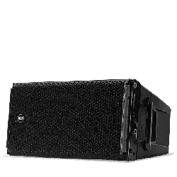
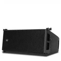
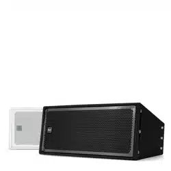
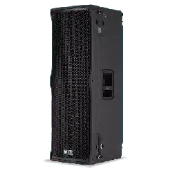
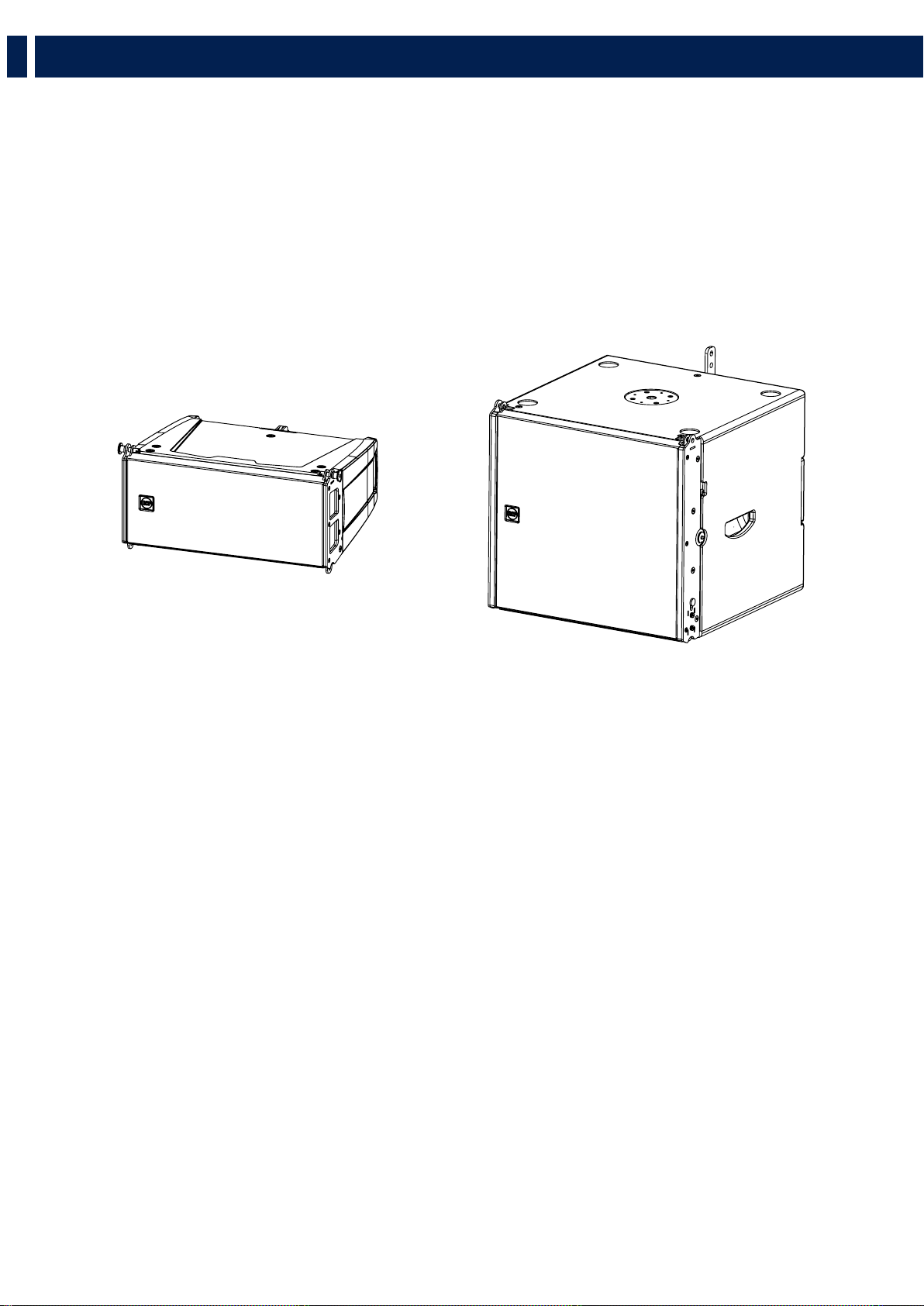
HL 6 - LINE ARRAY MODULE
HL 6 is two-way full range system, ideal when line array performance is needed, and a fast and easy set-up is a must. The concept of this speaker
derives from the touring industry, bringing in a compact cabinet all the experience of RCF professional sound. HL 6 features state-of-the art RCF
transducers, two powerful 6.0” woofers for a solid bass reproduction, plus a high powered 1.75” voice coil compression driver mounted on a
precise 100° x 10° waveguide to deliver vocal clarity with high definition and incredible dynamic. Due to its symmetrical design the HL 6 produces
constant coverage without break up or attenuation, maintaining intelligibility, definition, and signal strength over distance. HL 6 comes in a
structurally wooden reinforced composite polypropylene enclosure, and it is equipped with two rear handles for portability.
2. DESCRIPTION
HL 6
65 Hz ÷ 20000 Hz
2 x 6.0’’ Neo Woofers
1.75’’ neo Compression Driver
131 dB Max SPL
HL 35
40 Hz ÷ 140 Hz
15’’ Neo Woofer
134 dB Max SPL

7
EN
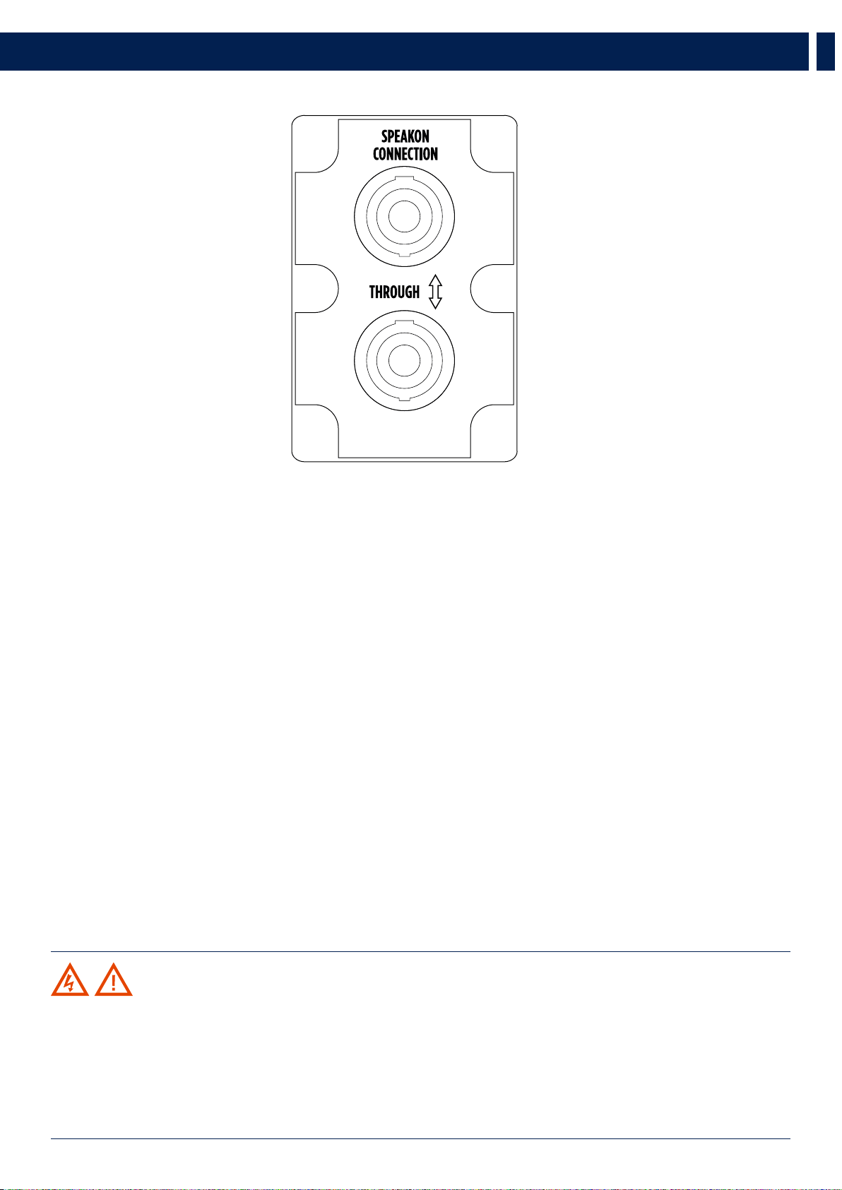
3. REAR PANEL
Both HL 6 and HL 35-S rear panels display 2 sockets, both for ‘Neutrik Speakon NL4’ (4-pole) plugs:
One of the two sockets (indifferentely) receives the signal; the other one becomes the “THROUGH” socket and be used to
link another speaker.
WARNING! CAUTION! Loudspeaker connections should be only made by qualified and experienced personnel
having the technical know-how or enough specific instructions (to ensure that connections are made correctly) in order to
prevent any electrical danger.
To prevent any risk of electric shock, do not connect loudspeakers when the amplifier is switched on.
Before turning the system on, check all connections and make sure there are no accidental short circuits.
The entire sound system shall be designed and installed in compliance with the current local laws and regulations regarding
electrical systems.
8
EN
4. RIGGING THE SYSTEM
RCF has developed a complete procedure to set up and hang a line array system starting from software data, enclosures, rigging, accessories,
cables, until the final installation.
WARNING! CAUTION! GENERAL RIGGING WARNINGS AND SAFETY PRECAUTIONS:
- Suspending loads should be done with extreme caution
- When deploying a system always wear protective helmets and footwear
- Never allow people to pass under the system during the installation process
- Never leave the system unattended during the installation process
- Never install the system over areas of public access
- Never attach other loads to the array system
- Never climb the system during or after the installation
- Never expose the system to extra loads created from the wind or snow
WARNING! CAUTION!
The system must be rigged in accordance with the laws and regulations of the Country where the system is used.
It is responsibility of the owner or rigger to make sure the system is properly rigged in accordance with Country and local
laws and regulations.
Always check that all the parts of the rigging system that are not provided from RCF are:
- Appropriate for the application
- Approved, certified and marked
- Properly rated
- In perfect condition
- Each cabinet support the full load of the part of the system below. It is very important that each single cabinet of the
system is properly checked
9
EN
4. RIGGING THE SYSTEM
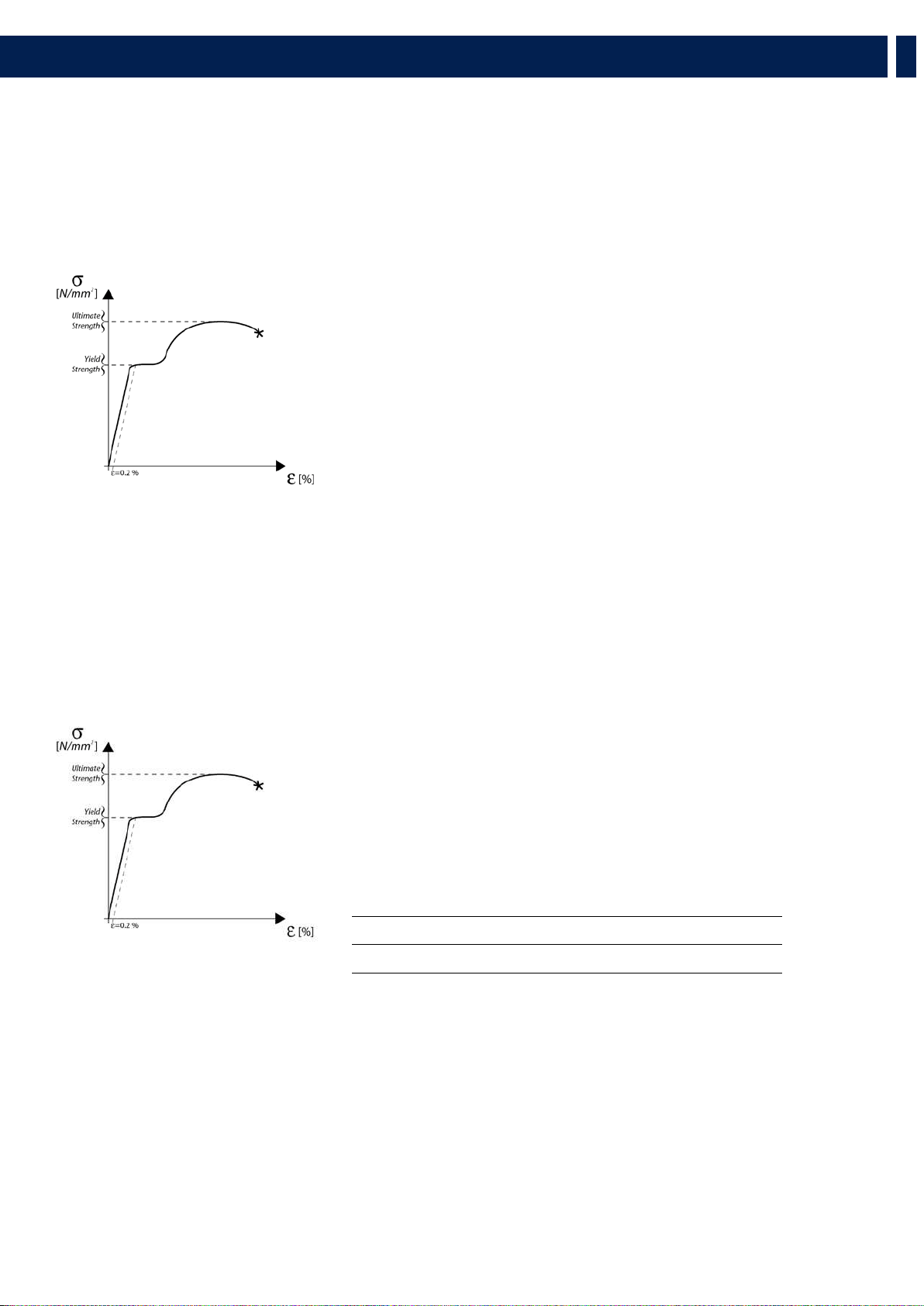
RCF SHAPE DESIGNER SOFTWARE AND SAFETY FACTOR
The suspension system is designed to have a proper safety factor (configuration dependent). Using the “RCF Easy Shape Designer”
software it is very easy to understand safety factors and limits for each specific configuration. To better comprehend in which safety
range the mechanics are working a simple introduction is needed: HL 6 arrays’ mechanics are built with certified UNI EN 10025 Steel.
RCF prediction software calculates forces on every single stressed part of the assembly and shows the minimum safety factor for every
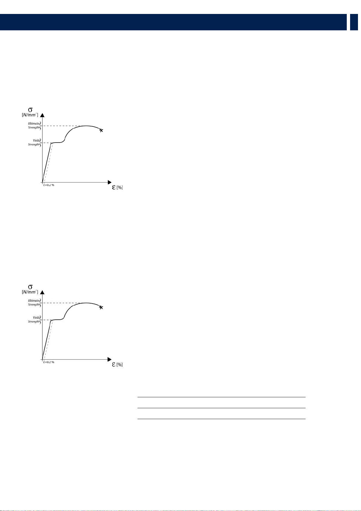
link. Structural steel has a stress-strain (or equivalent Force-Deformation) curve as in the following:
The curve is characterized by two critical points: the Break Point and the Yield
Point. The tensile ultimate stress is simply the maximum stress attained. Ultimate
tensile stress is commonly used as a criterion of the strength of the material for
structural design, but it should be recognized that other strength properties may often
be more important. One of these is certainly the Yield Strength. Stress-strain diagram
of structural steel exhibit a sharp break at a stress below the ultimate strength. At this
critical stress, the material elongates considerably with no apparent change in stress.
The stress at which this occurs is referred to as the Yield Point. Permanent deformation
may be detrimental, and the industry adopted 0.2% plastic strain as an arbitrary limit
that is considered acceptable by all regulatory agencies. For tension and compression,
the corresponding stress at this offset strain is defined as the yield.
In our prediction software the Safety Factors are calculated considering the Maximum Stress Limit equal to the Yield Strength,
according with many international standards and rules.
The resulting Safety Factor is the minimum of all the calculated safety factors, for each link or pin.
This is where you are working with a SF=7
Depending on local safety regulations and on the situation, the required safety
factor can vary. It is responsibility of the owner or rigger to make sure that
the system is properly rigged in accordance with Country and local laws and
regulations.
The “RCF Shape Designer” software gives detailed information of the safety factor
for each specific configuration.
The results are classified in four classes:
GREEN SAFETY FACTOR > 7 SUGGESTED
YELLOW 4 > SAFETY FACTOR > 7
ORANGE 1.5 > SAFETY FACTOR > 4
RED SAFETY FACTOR > 1.5 NEVER ADMITTED
10
EN
4. RIGGING THE SYSTEM
WARNING! CAUTION!
The safety factor is the result of the forces acting on fly bar’s and system’s front and rear links and pins and depends on many
variables:
- number of cabinets
- fly bar angles
- angles from cabinets to cabinets.
If one of the cited variables changes, the safety factor MUST BE recalculated using the software before rigging the system.
In case the fly bar is picked up from 2 motors, make sure the fly bar angle is correct. An angle different from the angle used in
the prediction software can be potentially dangerous.
Never allow persons to stay or pass under the system during the installation process.
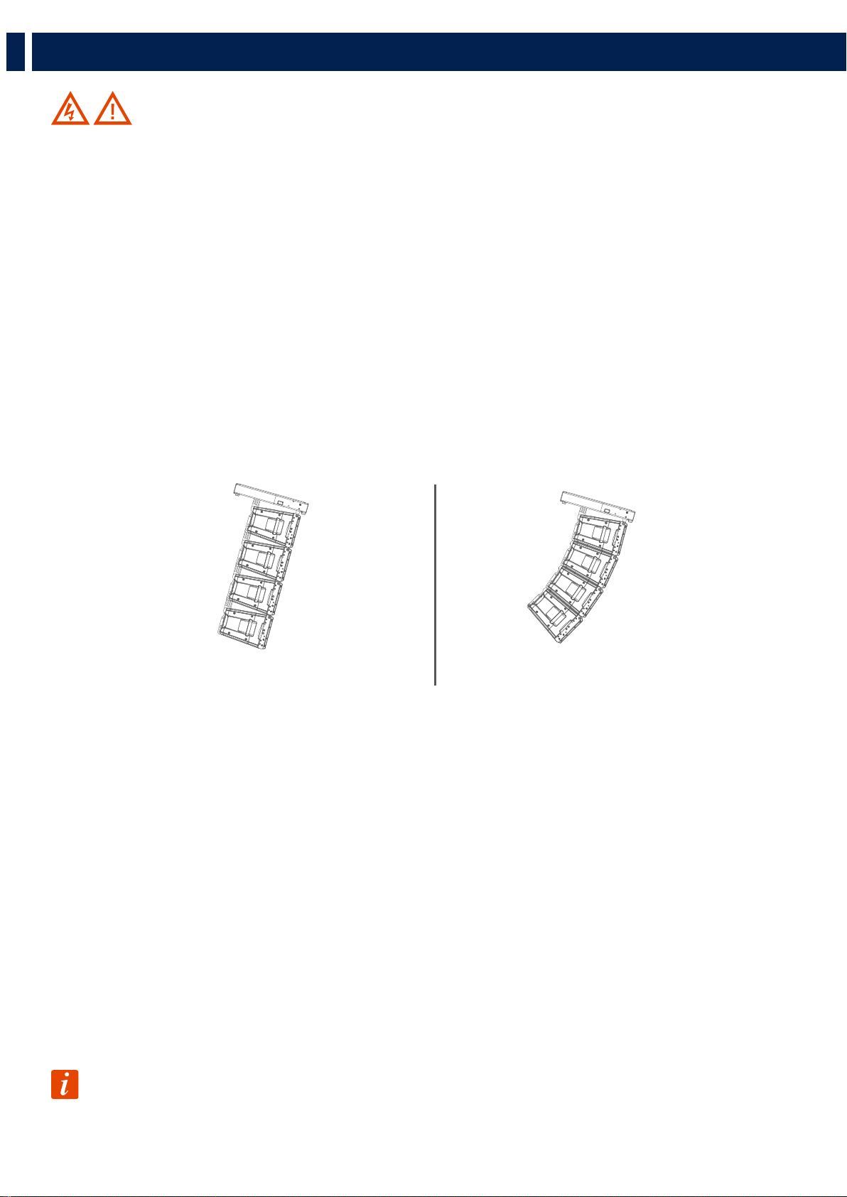
When the fly bar is particularly tilted or the array is very curved, the centre of gravity can move out from the rear links. In
this case the front links are in compression and the rear links are supporting the total weight of the system plus the front
compression. Always check very carefully with the “RCF Easy Shape Designer” software all this kind of situations (even with
a small number of cabinets).
PREDICTION SOFTWARE – SHAPE DESIGNER
RCF Easy Shape Designer is a temporary software, useful for the setup of the array, for mechanics and for proper preset suggestions.
The optimal setting of a loudspeaker array cannot ignore the basics of acoustics and the awareness that many factors contribute to a
sonic result that matches expectations. RCF provides the user with simple instruments that help the setting of the system in an easy
and reliable way.
This software will soon be replaced by a more complete software for multiple arrays and complex venue simulation with maps and
graphs of the results. RCF recommends this software to be used for each type of line array configuration.
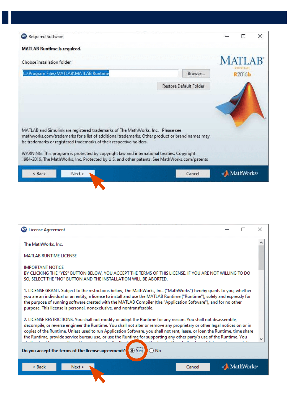
SOFTWARE INSTALLATION
The software was developed with Matlab 2015b and requires Matlab programming libraries. At the very first installation user
should refer to the installation package, available from the RCF website, containing the Matlab Runtime (ver. 9) or the installation
package that will download the Runtime from the web. Once the libraries are correctly installed, for all the following version of the
software the user can directly download the application without the Runtime. Two versions, 32-bit and 64-bit, are available for the
download.
IMPORTANT: Matlab no longer supports Windows XP and hence RCF EASY Shape Designer (32 bit) doesn’t
work with this OS version.
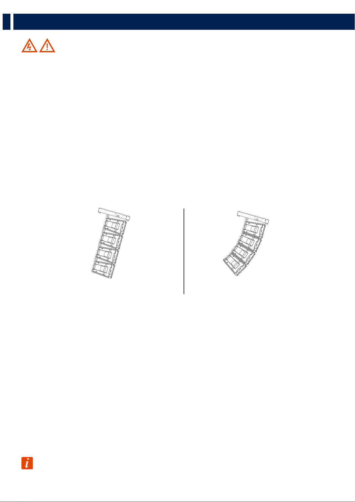
System particularly tilted System very curved
11
EN
4. RIGGING THE SYSTEM
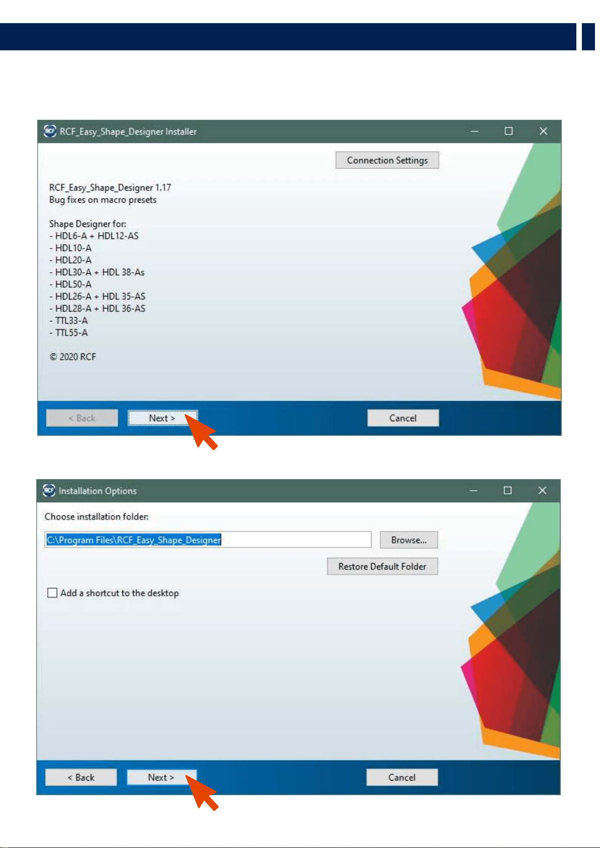
You may wait a few seconds after the double click on the installer because the software checks if Matlab Libraries are available.
After this step the installation begins. Double-click the last installer (check for the last release in the download section of our
website) and follow the next steps.

12
EN
After the choice of folders for the Shape Designer software (Figure 2) and Matlab Libraries Runtime the installer takes a couple of
minutes for the installation procedure.
4. RIGGING THE SYSTEM
13
EN
4. RIGGING THE SYSTEM
14
EN
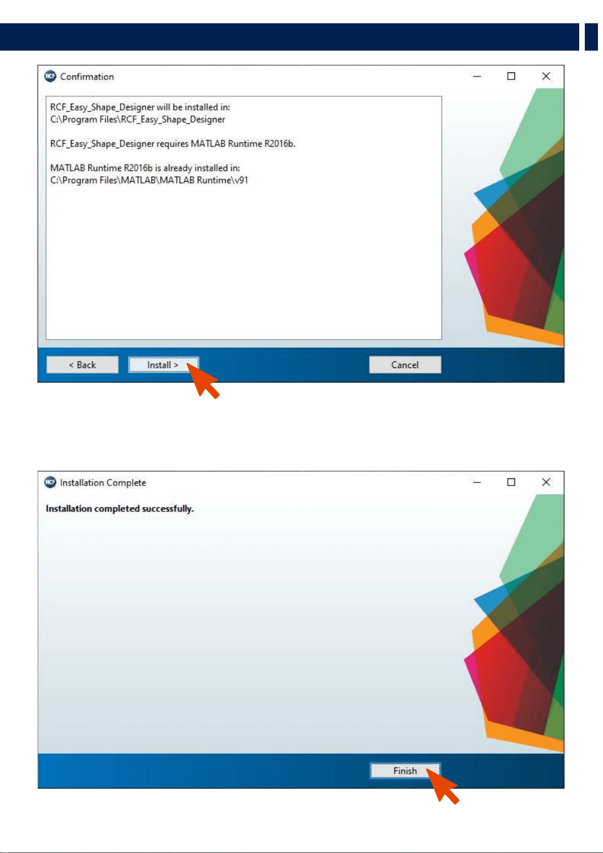
DESIGNING THE SYSTEM
The RCF Easy Shape Designer software is divided into two macro sections: the left part of the interface is dedicated to project
variables and data (size of audiences to cover, height, number of modules, etc.), the right part shows the processing results.
At first the user should introduce the audience data choosing the proper pop-up menu depending on the size of the audience and
introducing the geometrical data. It is also possible to define the height of the listener.
The second step is the array definition selecting the number of cabinets in the array, the hanging height, the number of hanging
points and the kind of available flybars. When selecting two hanging points consider those points positioned at the flybar extremes.
The height of the array should be considered referred to the bottom side of the flybar, as shown in the picture below.
After entering all the data input in the left part of the user interface, by pressing the AUTOSPLAY button the software will perform:
- Hanging point for the shackle with A or B position indicated if a single pickup point is selected, rear and front load if two
pickup points are selected.
- Flybar tilt angle and cabinet splays (angles that we have to set to each cabinet before lifting operations).
- Inclination that each cabinet will take (in case of one pick up point) or will have to take if we were to tilt the cluster with the
use of two engines. (two pick up points).
- Total load and Safety Factor calculation: if the selected setup doesn’t give Safety Factor > 1.5 the text message shows in red
color the failure to meet the minimum conditions of mechanical safety.
The autosplay algorithm was developed for optimum coverage of the audience size. The use of this function is recommended for
the optimization of the array aiming. A recursive algorithm chooses for every cabinet the best angle available in the mechanics.
HEIGHT
4. RIGGING THE SYSTEM

15
EN
RECOMMENDED WORKFLOW
Pending the official and definitive simulation software, RCF recommends the use of HL 6 Shape Designer together with
Ease Focus 3. Because of the need of interaction between different software, the recommended workflow assumes the
following steps for every array in the final project:
- Shape Designer: audience and array setup. Calculation in “autosplay” mode of flybar tilt, cabinet and splays.
- Focus 3: reports here the angles, tilt of flybar and presets generated by Shape Designer.
- Shape Designer: manual modify of splay angles if the simulation in Focus 3 does not give satisfactory results in order to
check the safety factor.
- Focus 3: reports here the new angles and tilt of flybar generated by Shape Designer. Repeat the procedure until good
results are achieved.
4. RIGGING THE SYSTEM

16
EN
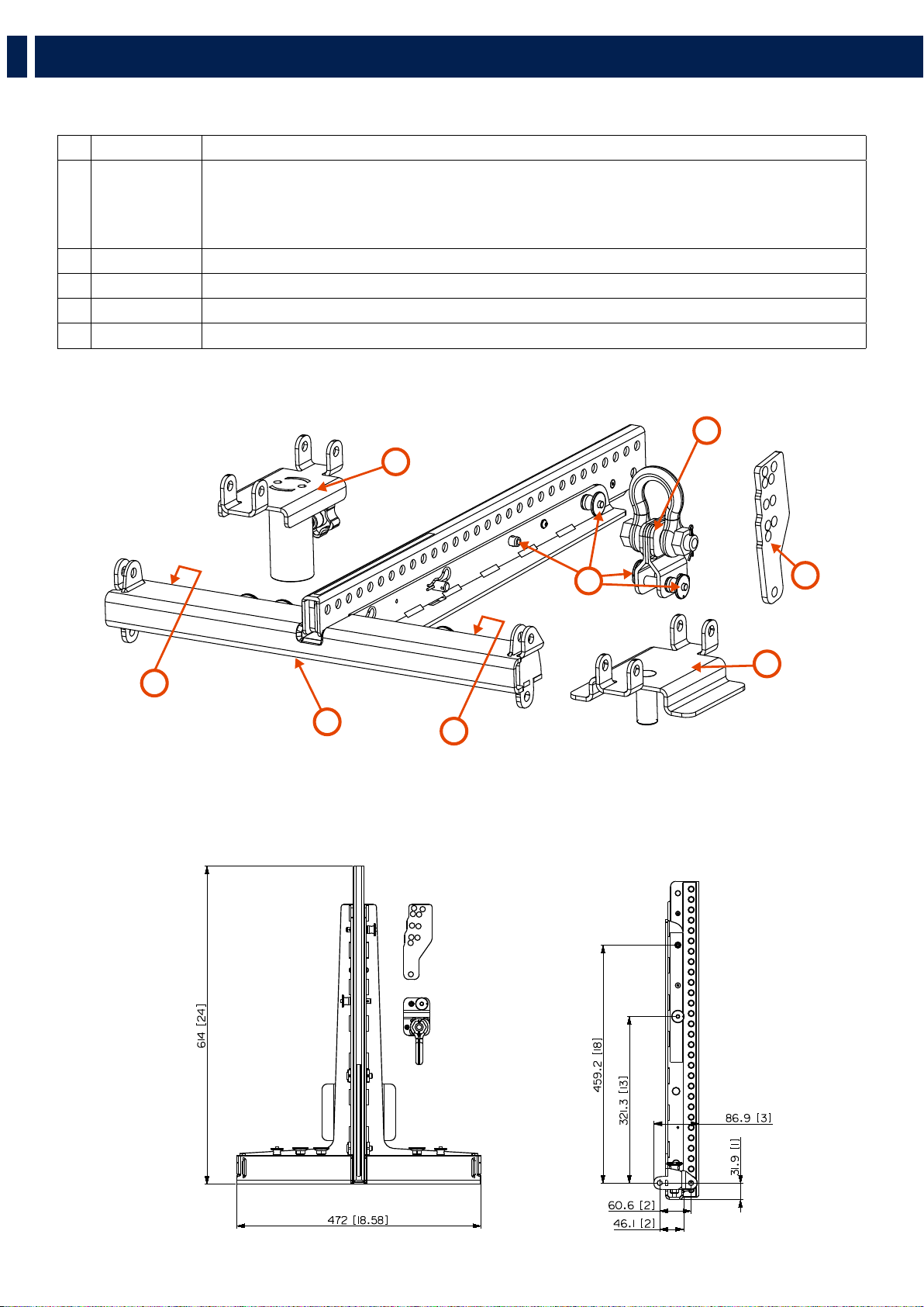
RIGGING COMPONENTS
Accessory p/n Description
1 13360360 BARRA SOSPENSIONE HDL6-A E HDL12-AS
- up to 16 HDL6-A
- up to 8 HDL12-AS
- up to 4 HDL12-AS + 8 HDL6-A
2 13360022 QUICK LOCK PIN
3
13360372 FLY BAR PICK UP HDL6-A
4 CONNECTION BRACKET FOR SECURELY LOCKING THE STACKING CLUSTER ON A SUBWOOFER
5 POLE MOUNT BRACKET
5
2
3
6
4
5
5
1
5. INSTALLATION

17
EN
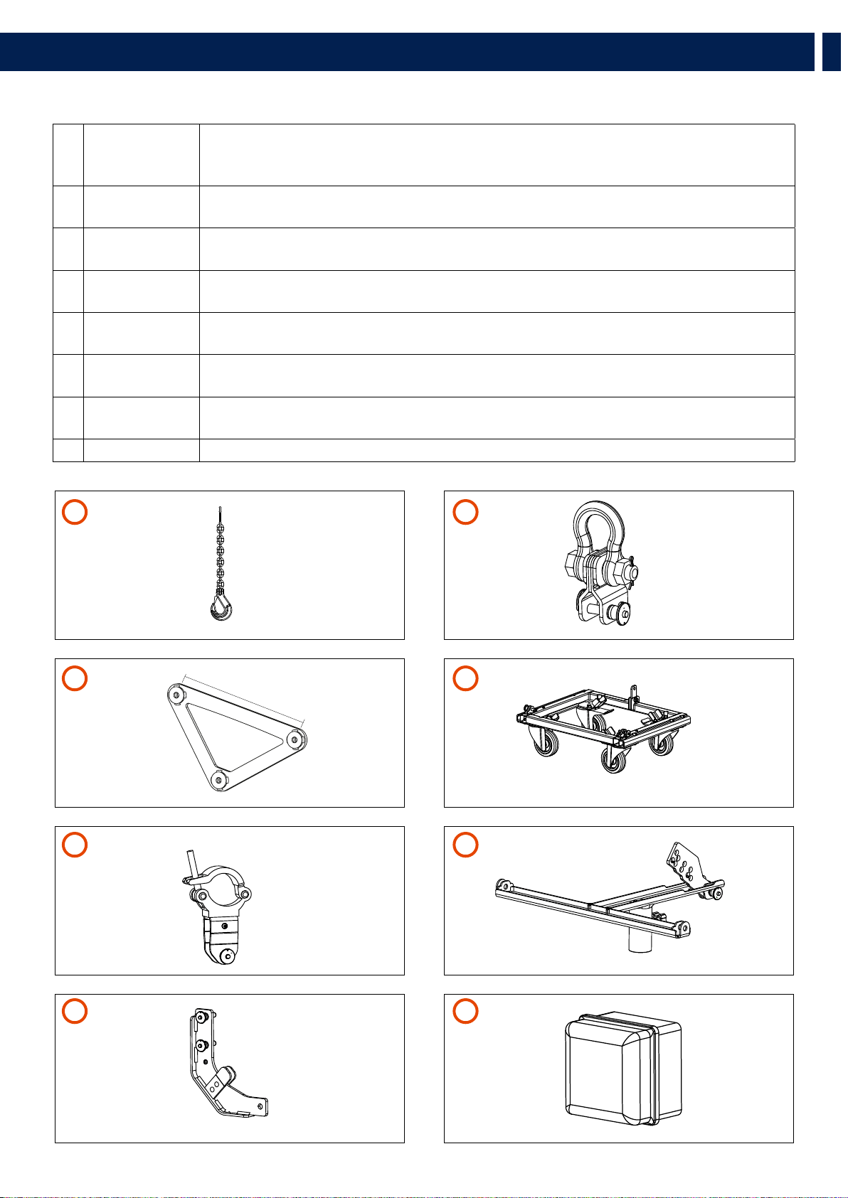
ACCESSORIES
1 13360129 HOIST SPACING CHAIN. It allows enough space for the hang of most 2 motor chain containers and
avoids any impact on the vertical balance of the array when it is suspended from a single pick-up
point.
2 13360372 FLY BAR PICK UP HDL6-A
+ 2 QUICK LOCK PIN (SPARE PART P/N 13360022)
3 13360351 AC 2X AZIMUT PLATE. It allows the horizontal aim control of the cluster. The system must be hooked
with 3 motors. 1 frontal and 2 attached to the azimuth plate.
4 13360366 KART WITH WHEELS AC KART HDL6
+ 2 QUICK LOCK PIN (SPARE PART 13360219)
5 13360371 AC TRUSS CLAMP HDL6
+ 1 QUICK LOCK PIN (SPARE PART P/N 13360022)
6 13360377 POLE MOUNT 3X HDL 6-A
+ 1 QUICK LOCK PIN (SPARE PART 13360219)
7 13360375 LINKBAR HDL12 TO HDL6
+ 2 QUICK LOCK PIN (SPARE PART 13360219)
8 13360381 RAIN COVER 06-01
500 mm
5. INSTALLATION
1
5
3
7
2
6
4
8

18
EN
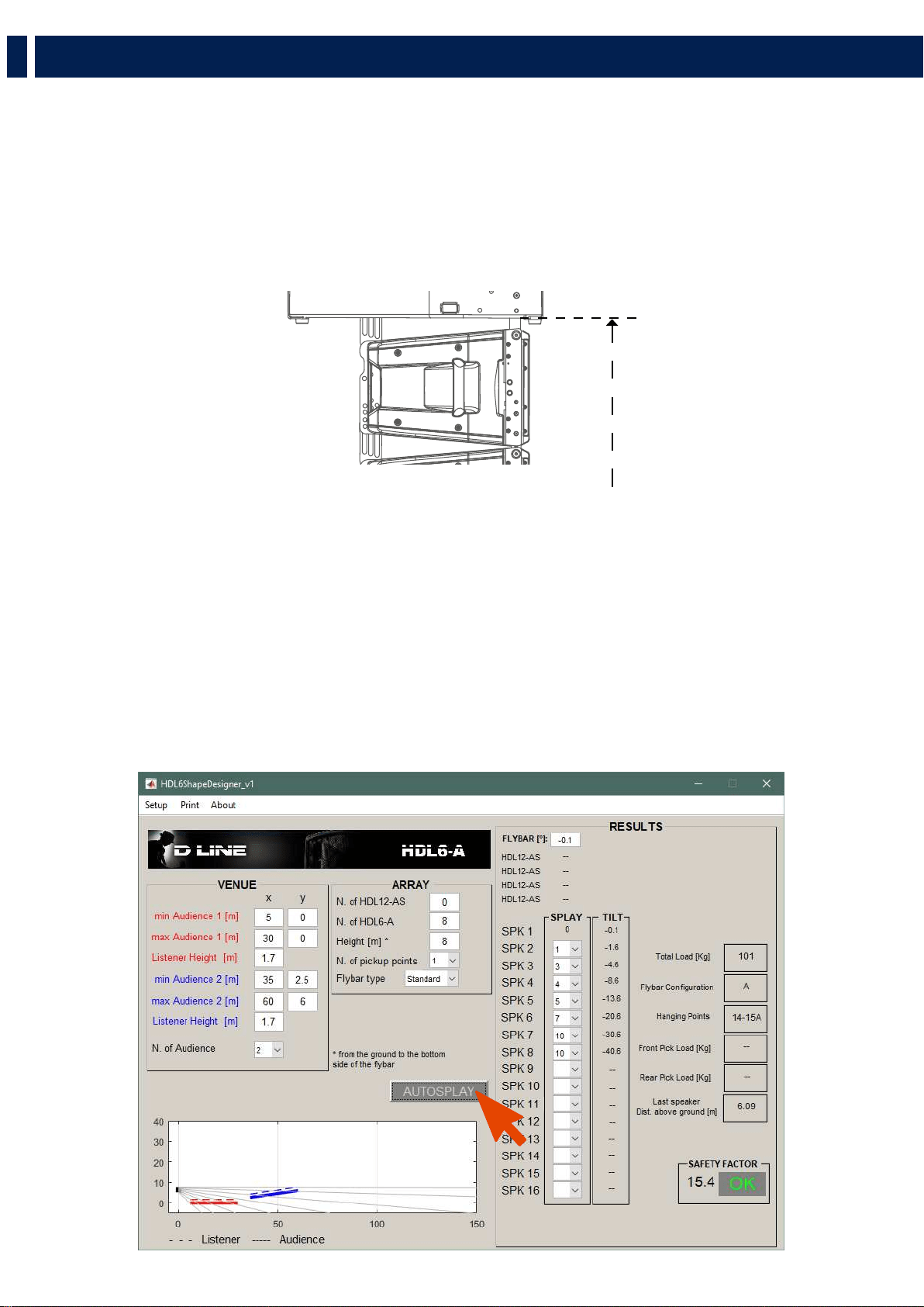
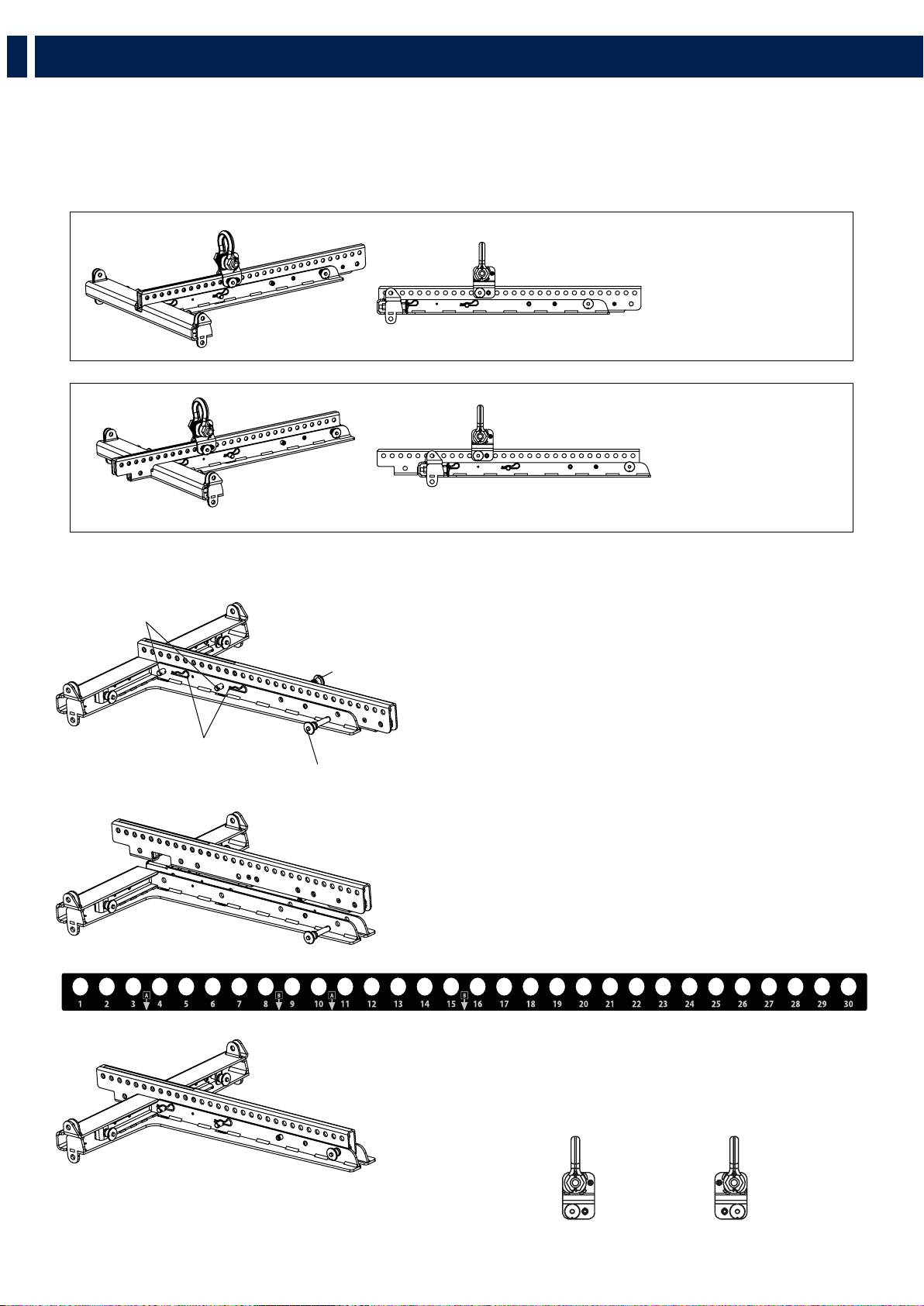
To set it in “B” configuration:
1. Remove the cotter pins “R”, pull out the linchpins “X” and
the quick lock pins “S”
2. Lift the central bar then re-position it making the “B”
indication on the label and the holes “S” match together.
3. Re-assemble the flybar repositioning the pins “S”, the
linchpins “X” and the cotter pins “R”.
HOW TO SET THE CENTRAL BAR IN “B” CONFIGURATION
CENTRAL BRACKET LABEL
FLYBAR
WITH CENTRAL BAR
IN “A” POSITION
FLYBAR
WITH CENTRAL BAR
IN “B” POSITION
4.1 - FLYBAR SETUP
The HL 6 flybar allows to set the central bar in two different configurations “A” e “B”.
This accessory is provided in “A” configuration. “B” configuration allows a better upper inclination of the cluster.
PICK UP POINT
“A” POSITION
PICK UP POINT
“B” POSITION
X
S
R
S
5. INSTALLATION
19
EN
4.2 - SYSTEM SUSPENSION PROCEDURE
SINGLE PICK UP POINT
Position the flybar pick-up point as shown in the software, respecting the position “A” or “B”.
DUAL PICK UP POINT
Allows to lift the cluster with two pulleys adding an optional pick up point.
PICK UP POINT
“A” POSITION
PICK UP POINT
“B” POSITION
PICK UP POINT
“A” POSITION
PICK UP POINT
“B” POSITION
5. INSTALLATION
20
EN
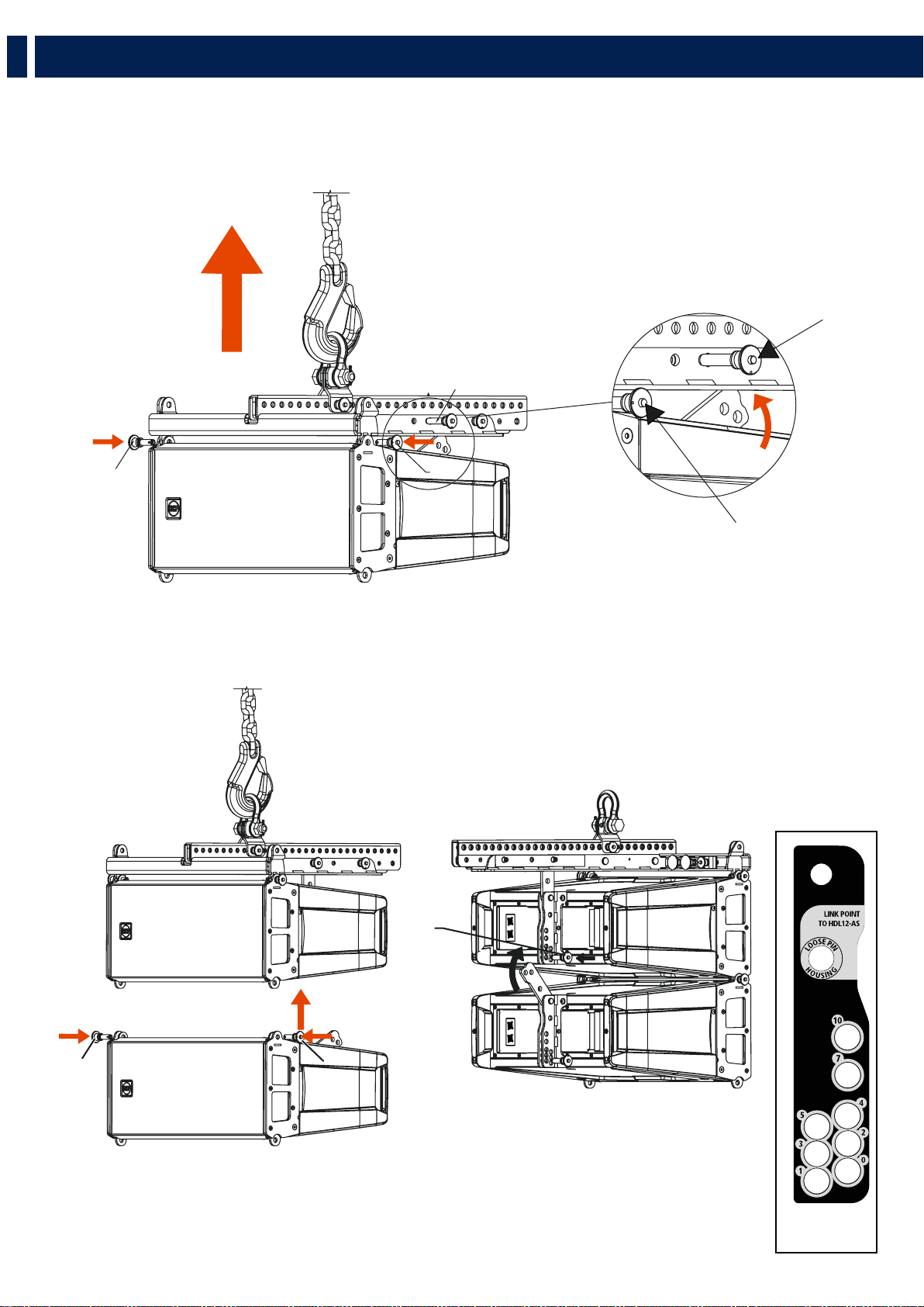
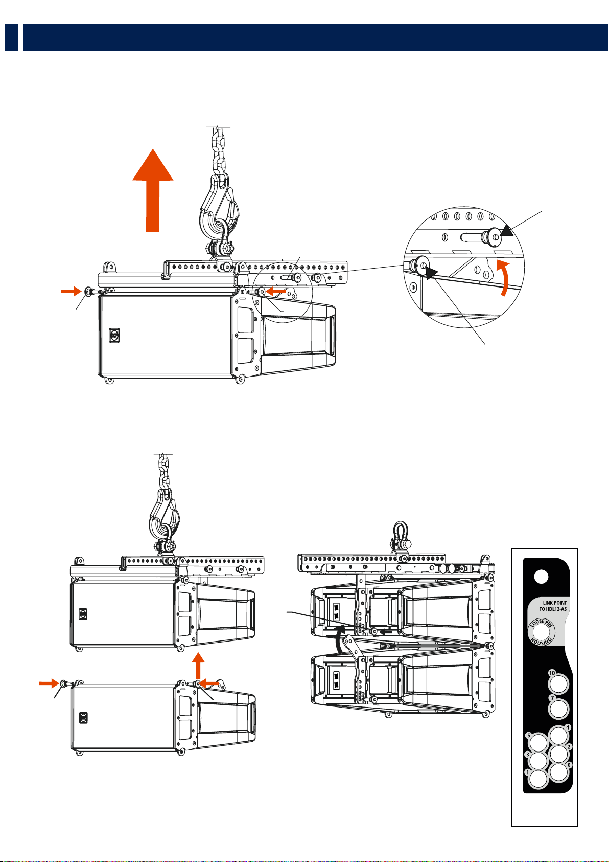
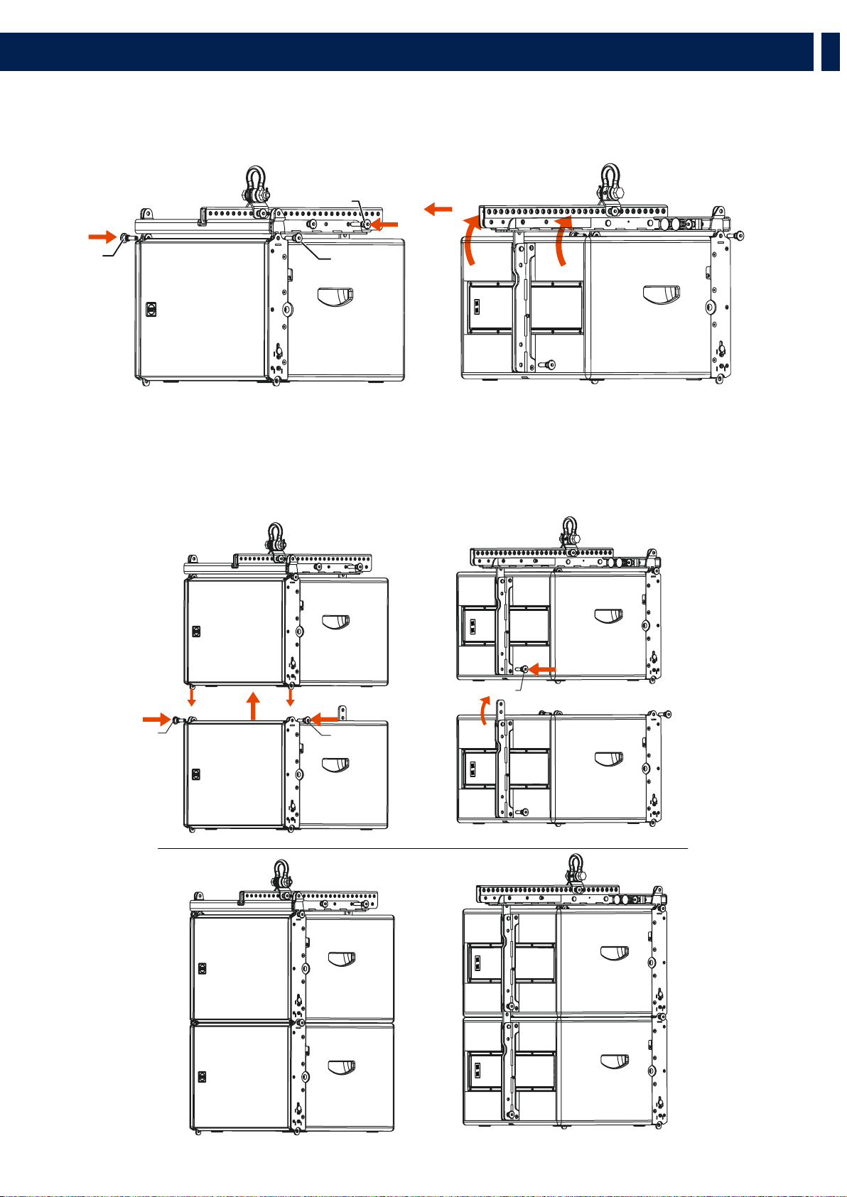
4.2.1 - SECURING THE FLYBAR TO THE FIRST HL 6 SPEAKER
1. Insert the frontal quick lock pins “F”
2. Rotate the rear bracket and secure it to the flybar with the rear quick lock pin “S” to the HL 6 Link Point hole
4.2.2 - SECURING THE SECOND HL 6 SPEAKER TO THE FIRST (AND CONSECUTIVE)
1. Secure the frontal quick lock pins “F”
2. Rotate the rear bracket and and secure it to the first speaker using the rear quick lock pin “P”, selecting the inclination angle as
shown on the software.
S
F
F
F
S
5. INSTALLATION
F
HDL6-A REAR
BRACKET LABEL
F
P

21
EN
4.2.3 - SECURING THE FLYBAR TO THE FIRST HL 35-S SPEAKER
1. Insert the frontal quick lock pins “F”
2. Rotate the rear bracket and secure it to the flybar with the rear quick lock pin “S” on the HL 35-S Link Point hole.
4.2.4 - SECURING THE SECOND HL 35-S SPEAKER TO THE FIRST (AND CONSECUTIVE)
1. Pull out the frontal bracket “A”
2. Secure the frontal quick lock pins “F”
3. Rotate the rear bracket and secure it to the first speaker using the rear quick lock pin “P”.
5. INSTALLATION
F
F
S
F
F
P
22
EN
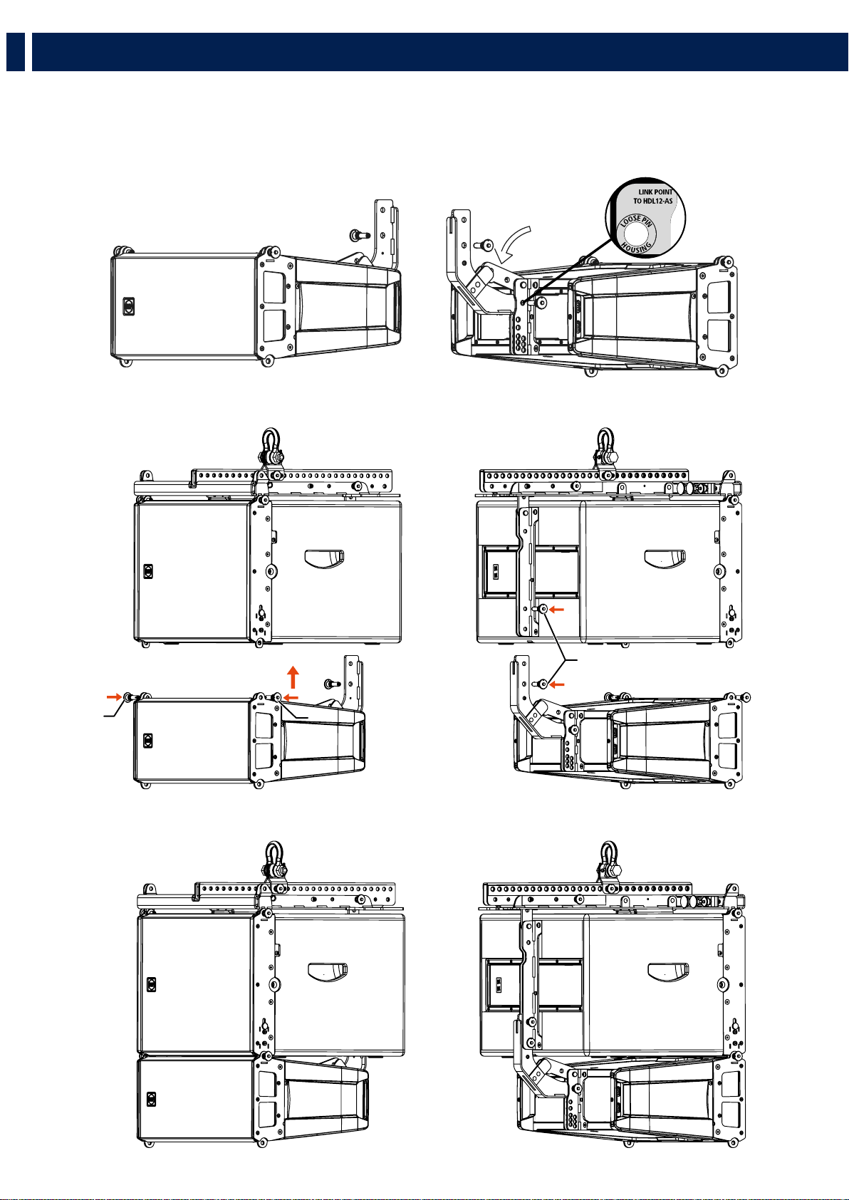
4.2.5 - CLUSTER HL 35-S + HL 6
1. Using the quick lock pin “P”, secure the linking bracket to the HL 6 speaker on the “Link point to HL 35-S” hole, on the rear
bracket.
2. Rotate the HL 6 rear bracket and block it on the linking bracket between the two metal flaps.
1. Secure HL 6 to HL 35-S using the frontal quick lock pins “F” and the rear ones “P”.
5. INSTALLATION
F
P
F
23
EN
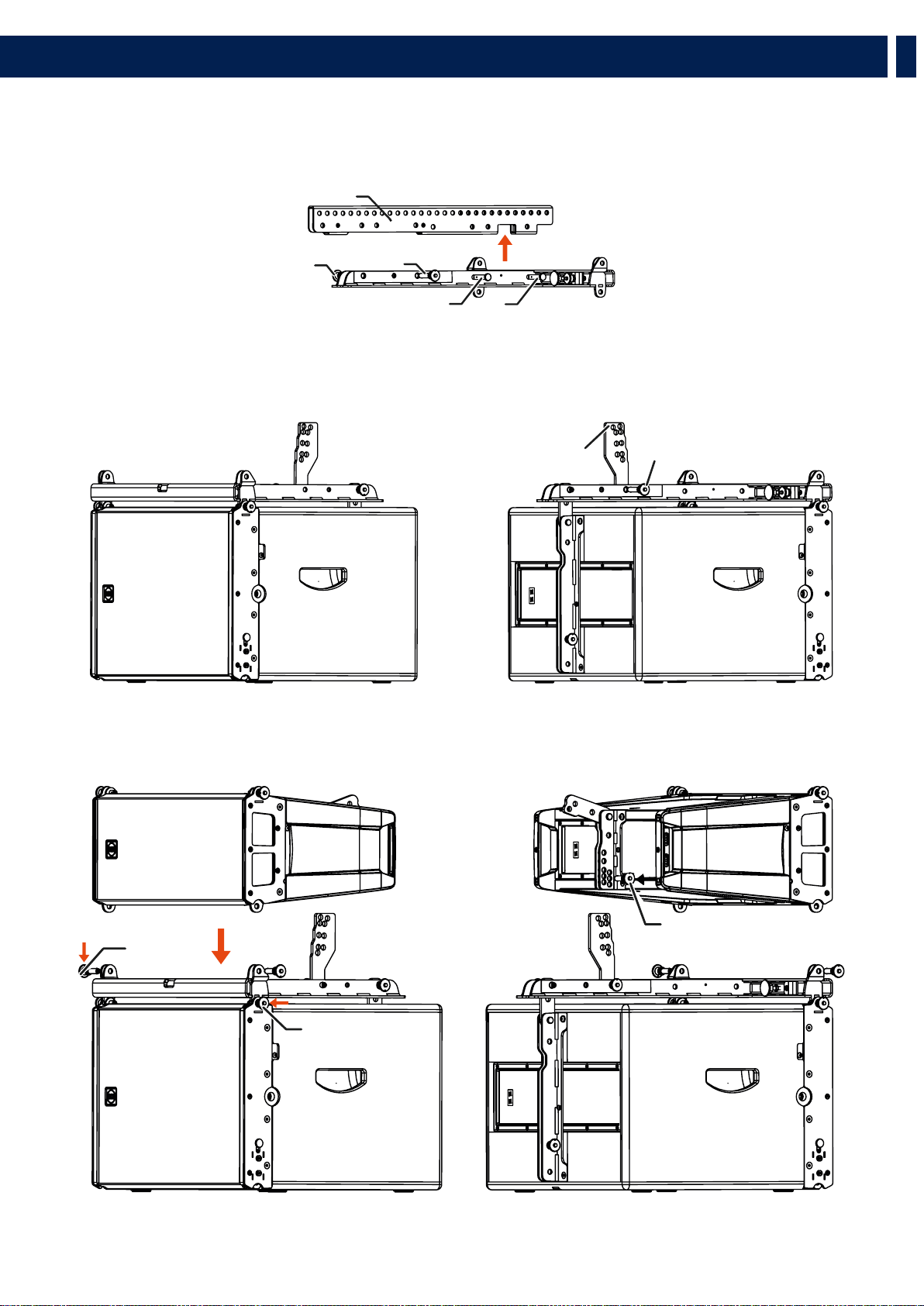
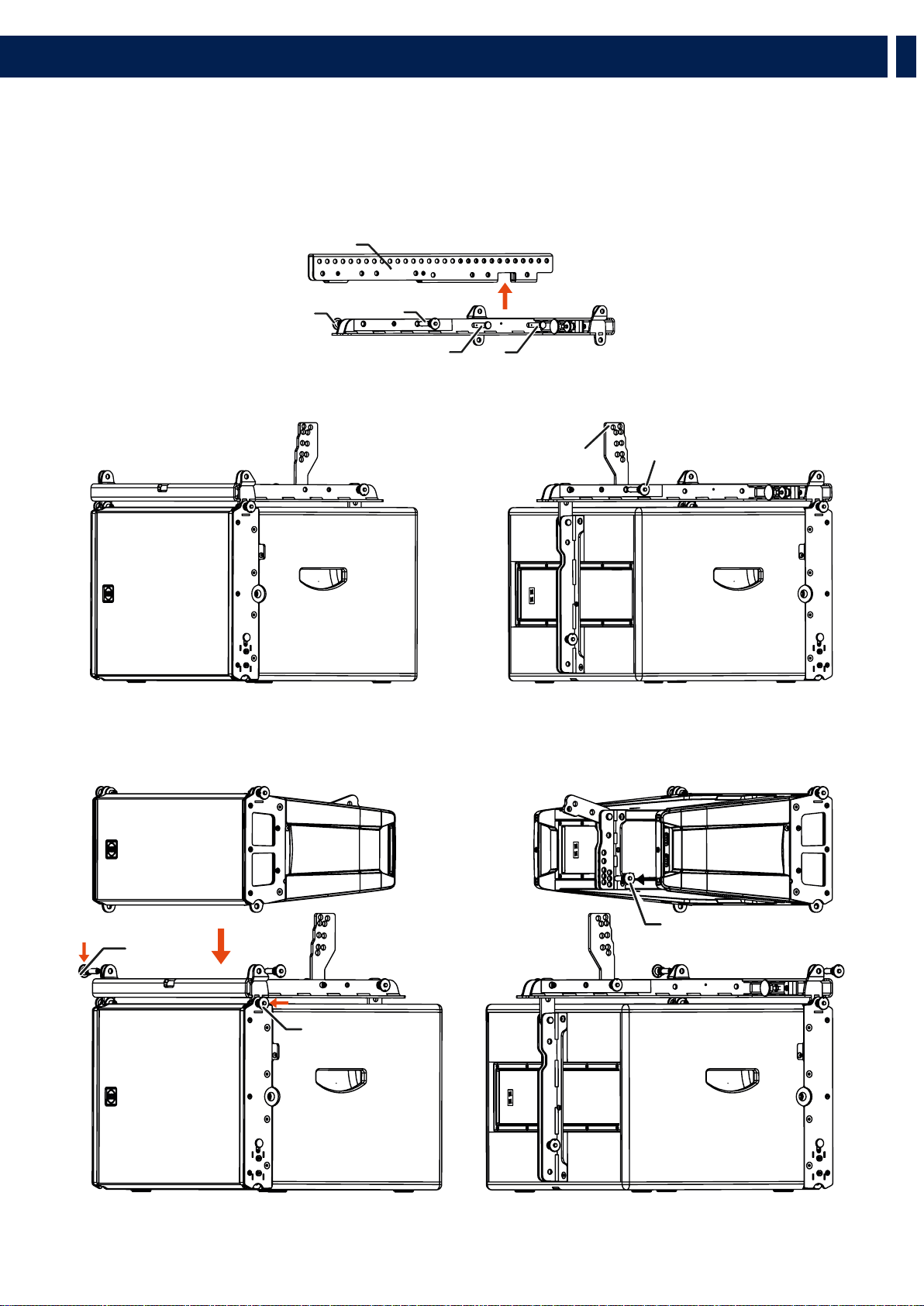
4.3 - STACKING PROCEDURE
Remove the central bar “A” from the flybar by pulling out the linchpins “X” and the quick lock pins “S”.
4.3.1 - STACKING ON SUB HL 35-S
Remove the central bar “A” from the flybar by pulling out the linchpins “X” and the quick lock pins “S”.
1. Secure the flybar to HL 35-S
2. Secure the stacking bar“B” (as shown in the picture) to the flybar using the quick lock pin “S” (follow the indication
“stacking point”)
1. Secure HL 6 to the flybar using the frontal quick lock pins “F1”.
A
S
S
XX
5. INSTALLATION
B
S
P
F1
F1

24
EN
2. Select the inclination angle (positive angles indicate a lower inclination of the speaker) and secure it with the rear quick lock pin “P”.
To obtain the speaker inclination (positive or negative) you need to match the stacking bar angle value with the same angle value
stated on the speaker rear bracket.
This method works for every inclination except for angles 10 and 7 of the stacking bar, for which you need to proceed in the
following way:
- angle 10 of the stacking bar needs to be matched with angle 0 on the speaker rear bracket.
- angle 7 of the stacking bar needs to be matched with angle 5 on the speaker rear bracket.
WARNING! Always verify the system solidity in every configuration.
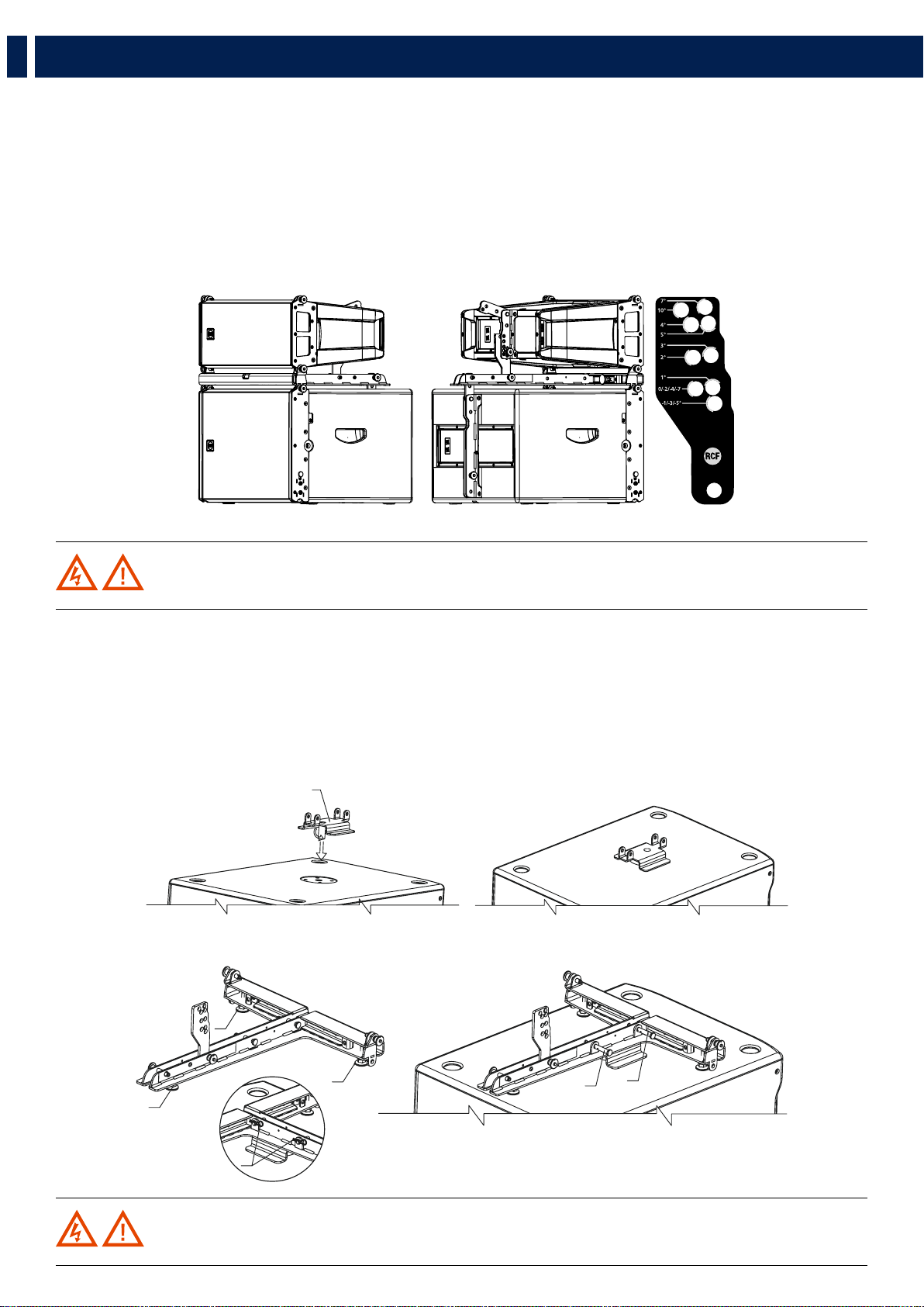
4.3.2 - STACKING ON DIFFERENT SUBWOOFERS (OTHER THAN HL 35-S)
1. Screw all three plastic feet “P”.
2. Secure the flybar to the safety bracket using the linchpins “X” and block them with the cotter pins “R”.
3. Adjust the feet to stabilize the flybar on the subwoofer then block them with thieir nuts to avoid unscrewing.
4. Assemble the HL 6 speaker with the same procedure.
WARNING! Always verify the system solidity in every configuration.
C
P
P
P
R
X
X
5. INSTALLATION

25
EN
WARNING! Always verify the system solidity in every configuration.
WARNING! Always verify the system solidity in every configuration and the pole payload.
4.3.3 - GROUND STACKING
1. Screw all three plastic feet “P”.
2. Adjust the feet to stabilize the flybar on the subwoofer then block them with thieir nuts to avoid unscrewing.
3. Assemble the HL 6 speaker with the same procedure.
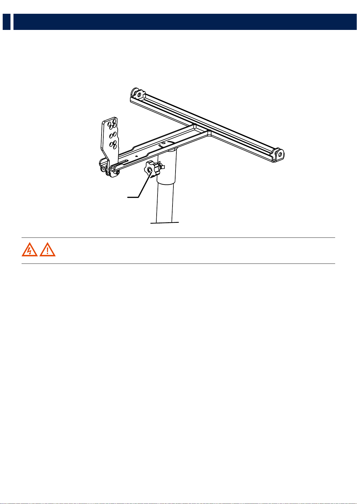
4.3.3 - POLE MOUNTING WITH SUSPENSION BAR
1. Secure the pole mount bracket to the flybar with the linchpins “X” then block them with the cotter pins “R”
2. Block the flybar to the pole by screwing the knob “M”.
3. Assemble the HL 6 speaker with the same procedure.
P
P
P
R
D
M
X
5. INSTALLATION

26
EN
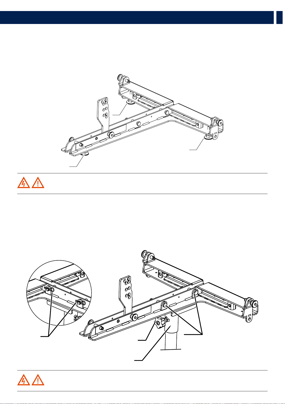
4.3.4 - POLE MOUNTING WITH POLE MOUNT 3X HL 6
1. Secure the flybar on the pole by screwing the knob “M”
2. Assemble the speakers HL 6 with the same procedure used on stacking on sub HL 35-S
M
WARNING! Always verify the system solidity in every configuration and the pole payload.
5. INSTALLATION
27
EN
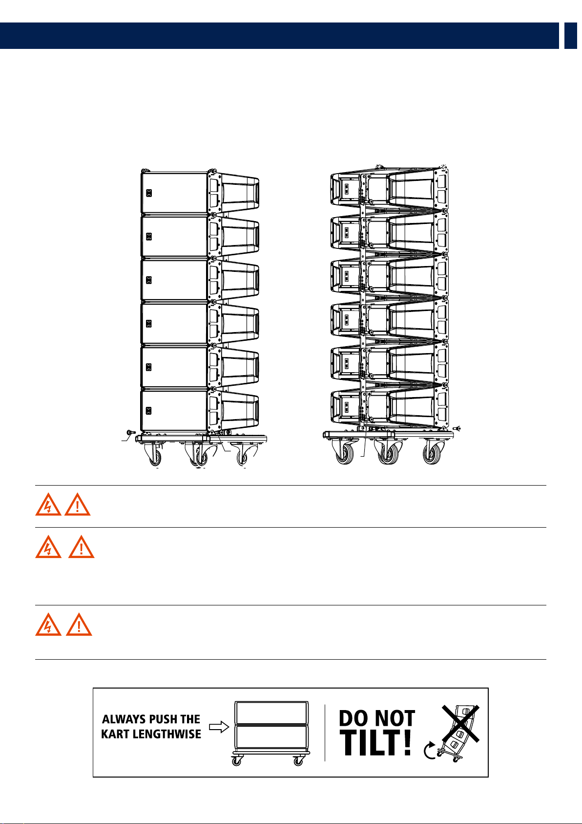
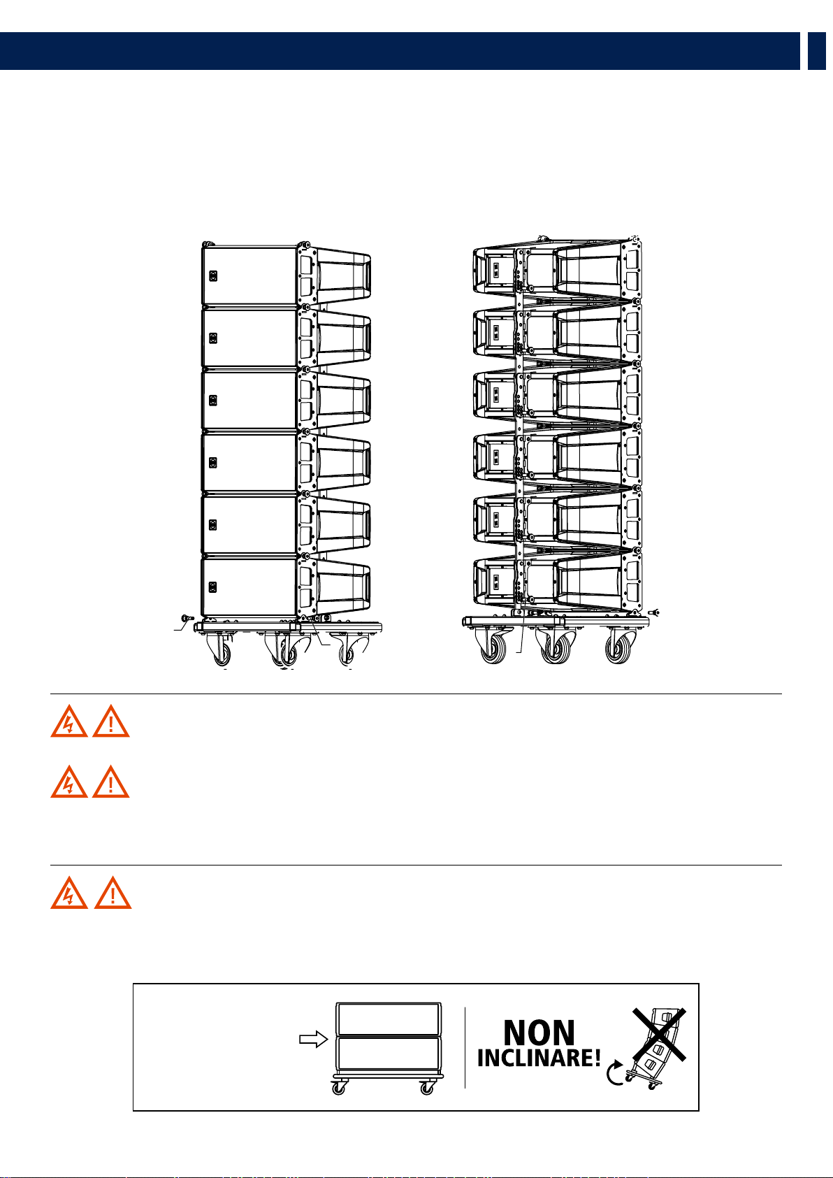
WARNING! The kart has been designed to carry up to 6 speakers. Do not stack more than six HL 6 on one kart.
WARNING! During transportation ensure the rigging components are not stressed or damaged by
mechanical forces. Use suitable transport cases. We recommend the use of the RCF original touring kart for this purpose.
Due to their surface treatment the rigging components are temporarily protected against moisture. However, ensure the
components are in a dry state while stored or during transportation and use.
WARNING! Exercise extreme caution when moving stacks of six cabinets with the Kart to avoid tipping.
Do not move stacks in the front-to-back direction of the HL 6 (the long side); always move stacks sideways to avoid tipping.
POSITIONING THE SPEAKERS ON THE KART
1. Secure the front side of the speaker to the kart using the quick lock pins “F”
2. Secure the rear side of the speaker to the kart using the quick lock pins “P”.
Careful: the hole to be used is 0° on the speaker rear bracket.
3. Proceed with the second speaker repeating steps “1” and “2”
6. TRANSPORTATION
FF
F
F
P
P
28
IT
1. AVVERTENZE PER LA SICUREZZA E INFORMAZIONI GENERALI
I simboli utilizzati in questo documento notificano importanti istruzioni operative e
avvertimenti che devono essere seguiti attentamente.
CAUTELA
Importante istruzione operativa: notifica
un pericolo che potrebbe danneggiare il
prodotto, compresa la perdita di dati
ATTENZIONE
Avvertimento importante riguardante l’uso
di voltaggi pericolosi e il potenziale rischio
di shock elettrico, lesioni personali o morte.
NOTE IMPORTANTI
Informazioni utili e rilevanti sull’argomento
SUPPORTI,
TROLLEY E
CARRRELLI
Informazioni riguardanti l’utilizzo di
supporti, trolley e carrelli. Suggerisce di
muovere con estrema cautela e di non
inclinare il carico.
SMALTIMENTO
Questo simbolo indica che il prodotto non
deve essere smaltito con i rifiuti ordinari,
così come indicato nella direttiva WEEE
(2012/19/EU) e nelle normative nazionali
in vigore.
NOTE IMPORTANTI
Questo manuale contiene informazioni importanti sull’uso corretto e sicuro del
dispositivo. Prima di collegare e utilizzare questo prodotto, leggere attentamente
questo manuale di istruzioni e tenerlo a portata di mano per riferimenti futuri.
Il manuale deve essere considerato parte integrante di questo prodotto e deve
accompagnarlo in caso di cambio proprietà come riferimento per la corretta
installazione e utilizzo nonché per le precauzioni di sicurezza. RCF S.p.A. non si
assume alcuna responsabilità per l’installazione e / o l’uso errati di questo prodotto.
PRECAUZIONI DI SICUREZZA
1. Tutte le precauzioni, in particolare quelle di sicurezza, devono essere lette con
particolare attenzione, in quanto forniscono informazioni importanti.
2. Alimentazione principale da rete elettrica
a. La tensione di rete è sufficientemente elevata da comportare un rischio di
folgorazione; installare e collegare questo prodotto prima di collegarlo.
b. Prima di accendere, assicurarsi che tutti i collegamenti siano stati eseguiti
correttamente e che la tensione della rete corrisponda alla tensione indicata
sulla targhetta dei dati sull’unità, in caso contrario, contattare il rivenditore RCF.
c. Le parti metalliche dell’unità sono messe a terra attraverso il cavo di
alimentazione. Un apparecchio con costruzione di CLASSE I deve essere
collegato a una presa di corrente con un collegamento di terra di protezione.
d. Proteggere il cavo di alimentazione da danni; assicurarsi che sia posizionato in
modo tale da non poter essere calpestato o schiacciato da oggetti.
e. Per evitare il rischio di scosse elettriche, non aprire mai questo prodotto: non
sono previste parti interne alle quali l’utente debba accedere.
f. Fare attenzione: nel caso di un prodotto provvisto solo di connettori POWERCON
e senza cavo di alimentazione, congiuntamente ai connettori POWERCON tipo
NAC3FCA (alimentazione) e NAC3FCB (alimentazione), devono essere usati i
seguenti cavi di alimentazione conformi alla norma nazionale:
- EU: cavo di tipo H05VV-F 3G 3x2.5 mm2 - Standard IEC 60227-1
- JP: cavo di tipo VCTF 3x2 mm2; 15Amp/120V~ - Standard JIS C3306
- US: cavo di tipo SJT/SJTO 3x14 AWG; 15Amp/125V~ - Standard ANSI/UL 62
3. Assicurarsi che nessun oggetto o liquido penetri in questo prodotto poiché ciò
potrebbe causare un corto circuito. Questo apparecchio non deve essere esposto a
gocciolamenti o spruzzi. Nessun oggetto riempito di liquido, come vasi, deve essere
posizionato su questo apparecchio. Nessuna fiamma libera (come candele accese)
deve essere posizionata su questo apparecchio.
4. Non tentare mai di eseguire operazioni, modifiche o riparazioni non
espressamente descritte nel presente manuale.
Contattare il centro di assistenza autorizzato o personale qualificato qualora si
verifichi una delle seguenti condizioni:
- Il prodotto non funziona (o funziona in modo anomalo).
- Il cavo di alimentazione è stato danneggiato.
- Oggetti o liquidi sono entrati nell’unità.
- Il prodotto ha subìto un forte urto.
5. Se questo prodotto non viene utilizzato per un lungo periodo, scollegare il cavo
di alimentazione.
6. Se questo prodotto inizia a emettere strani odori o fumo, spegnerlo
immediatamente e scollegare il cavo di alimentazione.
7. Non collegare questo prodotto ad apparecchiature o accessori non previsti.
Per l’installazione sospesa, utilizzare solo i punti di ancoraggio dedicati e non
tentare di appendere questo prodotto utilizzando elementi non idonei o non
specifici per questo scopo. Verificare inoltre l’idoneità della superficie di supporto a
cui è ancorato il prodotto (parete, soffitto, struttura, ecc.) a dei componenti utilizzati
per il fissaggio (tasselli, viti, staffe non fornite da RCF ecc.) che devono garantire
sicurezza del sistema / installazione nel tempo, anche considerando, ad esempio, le
vibrazioni meccaniche normalmente generate dai trasduttori.
Per evitare il rischio di caduta dell’apparecchiatura, non impilare più unità di questo
prodotto a meno che questa possibilità non sia specificata nel manuale dell’utente.
8.RCF S.p.A. raccomanda vivamente che questo prodotto sia installato
solo da installatori professionisti qualificati (o aziende specializzate)
che possono garantire la corretta installazione e certificarlo secondo le
normative vigenti.
L’intero sistema audio deve essere conforme agli standard e alle
normative vigenti in materia di sistemi elettrici.
9. Supporti, trolley e carrelli.
L’apparecchiatura deve essere utilizzata, ove necessario, solo su
supporti, trolley e carrelli consigliati dal produttore. L’apparecchiatura /
supporto / carrello deve essere spostata con estrema cautela. Arresti
improvvisi, eccessiva spinta e pavimenti irregolari possono causarne il
ribaltamento. Non inclinare mai.
10. Vi sono numerosi fattori meccanici ed elettrici da considerare quando si
installa un sistema audio professionale (oltre a quelli strettamente acustici, come la
pressione del suono, gli angoli di copertura, la risposta in frequenza, ecc.).
11. Perdita dell’udito.
L’esposizione a livelli sonori elevati può causare la perdita permanente dell’udito.
Il livello di pressione acustica che porta alla perdita dell’udito è diverso da persona
a persona e dipende dalla durata dell’esposizione. Per prevenire un’esposizione
potenzialmente pericolosa a livelli elevati di pressione acustica, chiunque sia
esposto a questi livelli dovrebbe usare adeguati dispositivi di protezione. Quando
viene utilizzato un trasduttore in grado di produrre alti livelli sonori, è quindi
necessario indossare tappi per le orecchie o cuffie protettive. Vedere le specifiche
tecniche del manuale per conoscere il livello massimo di pressione sonora.
PRECAUZIONI OPERATIVE
- Posizionare questo prodotto lontano da qualsiasi fonte di calore e garantire
sempre un’adeguata circolazione dell’aria attorno ad esso.
- Non sovraccaricare questo prodotto per molto tempo.
- Non forzare mai gli elementi di controllo (tasti, manopole, ecc.).
- Non utilizzare solventi, alcool, benzene o altre sostanze volatili per pulire le
parti esterne di questo prodotto.
NOTE IMPORTANTI
Per evitare il verificarsi di disturbi sui cavi di segnale in linea, utilizzare solo cavi
schermati ed evitare di avvicinarli a:
- Apparecchiature che producono campi elettromagnetici ad alta
intensità
- Cavi di alimentazione
- Linee di altoparlanti
29
IT
1. AVVERTENZE PER LA SICUREZZA E INFORMAZIONI GENERALI
ATTENZIONE! CAUTELA! Per evitare il rischio di incendi o
scosse elettriche, non esporre mai questo prodotto a pioggia o umidità.
ATTENZIONE! Per evitare il rischio di scosse elettriche, non collegare
all’alimentazione di rete mentre la griglia è rimossa.
WARNING! Per ridurre il rischio di scosse elettriche, non smontare
questo prodotto se non si è qualificati. Per l’assistenza rivolgersi a personale
di assistenza qualificato
SMALTIMENTO CORRETTO DI QUESTO PRODOTTO
Questo prodotto deve essere consegnato a un sito di raccolta
autorizzato per il riciclaggio di apparecchiature elettriche ed
elettroniche (AEE). Una manipolazione impropria di questo tipo di
rifiuti potrebbe avere un possibile impatto negativo sull’ambiente
e sulla salute umana a causa di sostanze potenzialmente pericolose che
sono generalmente associati alle AEE. Allo stesso tempo, la vostra
collaborazione per il corretto smaltimento di questo prodotto
contribuirà all’utilizzo efficace delle risorse naturali. Per ulteriori
informazioni su dove sia possibile scaricare le attrezzature per il
riciclaggio, si prega di contattare l’ufficio comunale locale, l’autorità
competente per i rifiuti o il servizio di smaltimento dei rifiuti domestici
.
CURA E MANUTENZIONE
Per garantire un servizio di lunga durata, questo prodotto deve essere utilizzato seguendo
questi consigli:
- Se il prodotto deve essere installato all’aperto, assicurarsi che sia coperto e
protetto da pioggia e umidità.
- Se il prodotto deve essere utilizzato in un ambiente freddo, riscaldare lentamente
le bobine vocali inviando un segnale di basso livello per circa 15 minuti prima
di inviare segnali ad alta potenza.
- Utilizzare sempre un panno asciutto per pulire le superfici esterne
dell’altoparlante e farlo sempre quando l’alimentazione è spenta
CAUTELA! Per evitare di danneggiare le finiture esterne non
utilizzare solventi per la pulizia o abrasivi.
ATTENZIONE! CAUTELA! Per gli altoparlanti alimentati,
eseguire la pulizia solo quando l’alimentazione è spenta.
RCF S.p.A. si riserva il diritto di apportare modifiche
senza preavviso per rettificare eventuali errori e/o
omissioni.
Fare sempre riferimento all’ultima versione del
manuale su www.rcf.it.

30
IT
HL 6 - DIFFUSORE LINE ARRAY
HL 6 è un sistema full range a due vie, ideale quando sono necessarie prestazioni line array e una configurazione facile e veloce. Il concetto di
questo diffusore deriva dal mondo del touring, racchiudendo in un cabinet compatto tutta l’esperienza del suono professionale RCF.
HL 6 è dotato di trasduttori RCF all’avanguardia, due potenti woofer da 6,0” per una solida riproduzione dei bassi, oltre a un driver a compressione
da 1,75” ad alta potenza montato su una guida d’onda ad alta precisione di 100° x 10° in modo da offrire un’incredibile dinamica e una
chiarezza vocale ad altissima definizione. Grazie al suo design simmetrico, l’HL 6 produce una copertura costante senza interruzioni o attenuazioni,
mantenendo l’intelligibilità, la definizione e la potenza del segnale anche a lunga distanza. HL 6 viene fornito in una custodia in polipropilene
composito rinforzato strutturalmente in legno ed è dotato di due maniglie posteriori per una facile e comoda portabilità.
2. DESCRIZIONE
HL 6
65 Hz ÷ 20000 Hz
2 x 6.0’’ Neo Woofers
1.75’’ neo Compression Driver
131 dB Max SPL
HL 35
40 Hz ÷ 140 Hz
15’’ Neo Woofer
134 dB Max SPL
31
IT
3. PANNELLO POSTERIORE
ATTENZIONE! CAUTELA! I collegamenti dei diffusori devono essere effettuati solo da personale qualificato
ed esperto in possesso del know-how tecnico o di istruzioni specifiche sufficienti (per garantire che i collegamenti siano
effettuati correttamente) al fine di prevenire qualsiasi pericolo elettrico.
Per evitare qualsiasi rischio di scossa elettrica, non collegare altoparlanti quando l’amplificatore è acceso.
Prima di accendere il sistema, controllare tutti i collegamenti e assicurarsi che non vi siano cortocircuiti accidentali.
L’intero sistema di diffusione sonora deve essere progettato e installato in conformità con le leggi e le normative locali vigenti
in materia di impianti elettrici
Entrambi i pannelli posteriori di HL 6 e HL 35-S presentano due prese, entrambe per connettori‘Neutrik Speakon NL4’ (a 4 poli):
Una delle due prese (indifferentemente) riceve il segnale; l’altra presa diventa la presa “THROUGH” e può essere usata per
rilanciare il segnale a un altro diffusore.
32
IT
4. APPENDIMENTO DEL SISTEMA
RCF ha sviluppato una procedura completa per configurare e sospendere un sistema line array a partire da dati software, custodie, rigging,
accessori, cavi, fino all’installazione finale.
ATTENZIONE! CAUTELA! AVVERTENZE GENERALI PER L’ATTREZZATURA E PRECAUZIONI DI SICUREZZA:
- La sospensione dei carichi deve essere eseguita con estrema cautela
- Quando si sospende il sistema indossare sempre caschi e calzature protettive
- Non consentire mai a persone di passare sotto al sistema durante il processo di installazione
- Non lasciare mai il sistema incustodito durante il processo di installazione
- Non installare mai il sistema su aree di pubblico accesso
- Non collegare mai altri carichi al sistema array
- Non salire mai sul sistema durante o dopo l’installazione
- Non esporre mai il sistema a carichi aggiuntivi creati dal vento o dalla neve
WARNING! CAUTION!
L’impianto deve essere predisposto in conformità alle leggi e ai regolamenti del Paese in cui l’impianto viene utilizzato.
È responsabilità del proprietario o dell’operatore assicurarsi che il sistema sia adeguatamente attrezzato in conformità con le
leggi e i regolamenti nazionali e locali.
Verificare sempre che tutte le parti del sistema non fornite da RCF siano:
- Adatte per l’applicazione
- Approvate, certificate e marcate
- Vlutate correttamente
- In perfette condizioni
- Ogni modulo supporta l’intero carico della parte del sistema sottostante. È molto importante che ogni singolo modulo del
sistema sia adeguatamente controllato
33
IT
4. APPENDIMENTO DEL SISTEMA
SOFTWARE RCF SHAPE DESIGNER E FATTORE DI SICUREZZA
Il sistema di sospensione è progettato per avere un fattore di sicurezza adeguato (dipendente dalla configurazione). Utilizzando il
software “RCF Easy Shape Designer” è molto facile comprendere i fattori di sicurezza e i limiti per ogni specifica configurazione.
Per comprendere meglio in quale range di sicurezza operano le meccaniche è necessaria una semplice introduzione: le meccaniche
degli array HL 6 sono costruite con Acciaio certificato UNI EN 10025. Il software di previsione RCF calcola le forze su ogni singola
parte sollecitata dell’assieme e mostra il fattore di sicurezza minimo per ogni collegamento. L’acciaio strutturale ha una curva sforzo-
deformazione rappresentata nel seguente grafico:
La curva è caratterizzata da due punti critici: il Break Point e lo Yield Point. La tensione
massima di trazione è semplicemente la massima tensione raggiunta. Lo sforzo di
trazione finale è comunemente usato come criterio della resistenza del materiale per la
progettazione strutturale, ma si dovrebbe riconoscere che altre proprietà di resistenza
possono spesso essere più importanti. Uno di questi è sicuramente il Yield Strength.
Il diagramma sforzo-deformazione dell’acciaio strutturale mostra una rottura netta a
una sollecitazione inferiore all’ultima resistenza. A questo stress critico, il materiale si
allunga considerevolmente senza alcun cambiamento apparente dello stress. Lo stress
a cui ciò si verifica è indicato come punto di snervamento. La deformazione permanente
può essere dannosa e generalmente viene adottato lo 0,2% di deformazione plastica
come limite arbitrario considerato accettabile da tutte le agenzie di regolamentazione.
Per trazione e compressione, la sollecitazione corrispondente a questa deformazione di offset è definita come snervamento.
Nel nostro software di previsione i Fattori di sicurezza sono calcolati considerando il limite massimo di sollecitazione pari al
carico di snervamento, secondo molti standard e regole internazionali.
Il fattore di sicurezza risultante è il minimo di tutti i fattori di sicurezza calcolati, per
ogni collegamento o perno.
Qui è dove stai lavorando con un SF=7
A seconda delle normative di sicurezza locali e della situazione, il fattore di sicurezza
richiesto può variare. È responsabilità del proprietario o dell’operatore assicurarsi che
il sistema sia adeguatamente attrezzato in conformità con le leggi e i regolamenti
nazionali e locali.
Il software “RCF Shape Designer” fornisce informazioni dettagliate sul fattore di
sicurezza per ogni specifica configurazione.
I risultati sono classificati in quattro classi:
GREEN SAFETY FACTOR > 7 SUGGESTED
YELLOW 4 > SAFETY FACTOR > 7
ORANGE 1.5 > SAFETY FACTOR > 4
RED SAFETY FACTOR > 1.5 NEVER ADMITTED
34
IT
4. APPENDIMENTO DEL SISTEMA
ATTENZIONE! CAUTELA!
Il fattore di sicurezza è il risultato delle forze che agiscono sui collegamenti e sui perni anteriori e posteriori del fly bar e del
sistema e dipende da molte variabili:
- numero di moduli
- inclinazione del fly bar
- angolazione tra i moduli
Se una delle variabili citate cambia, il fattore di sicurezza DEVE ESSERE ricalcolato tramite il software prima di armare il
sistema.
Nel caso in cui il fly bar venga sollevato da 2 motori, assicurarsi che l’inclinazione del fly bar sia corretta. Un’inclinazione
diversa da quella utilizzata nel software di previsione può essere potenzialmente pericolosa.
Non consentire mai a persone di sostare o passare sotto il sistema durante il processo di installazione.
Quando il fly bar è particolarmente inclinato o l’array è molto curvo, il baricentro può allontanarsi dai bracci posteriori. In
questo caso i collegamenti anteriori sono in compressione e i collegamenti posteriori supportano il peso totale del sistema
più la compressione anteriore. Verificare sempre molto attentamente con il software “RCF Easy Shape Designer” tutte queste
situazioni (anche con un numero ridotto di armadi).
PREDICTION SOFTWARE – SHAPE DESIGNER
RCF Easy Shape Designer è un software temporaneo, utile per il setup dell’array, per la meccanica e per i corretti suggerimenti di
preset.
L’impostazione ottimale di un array di diffusori non può prescindere dalle basi dell’acustica e dalla consapevolezza che molti fattori
contribuiscono a un risultato sonoro all’altezza delle aspettative. RCF mette a disposizione dell’utente strumenti semplici che aiutano
la messa a punto del sistema in modo facile ed affidabile.
Questo software sarà presto sostituito da un software più completo per array multipli e per la simulazione di applicazioni complesse
con mappe e grafici dei risultati. RCF consiglia l’utilizzo di questo software per ogni tipo di configurazione di array di linee.
SOFTWARE INSTALLATION
Il software è stato sviluppato con Matlab 2015b e richiede librerie di programmazione Matlab. Alla prima installazione l’utente
deve fare riferimento al pacchetto di installazione, disponibile dal sito RCF, contenente Matlab Runtime (ver. 9) o al pacchetto di
installazione che scaricherà il Runtime dal web. Una volta che le librerie sono state correttamente installate, per tutte le versioni
successive del software l’utente può scaricare direttamente l’applicazione senza il Runtime. Sono disponibili per il download due
versioni, 32 bit e 64 bit.
IMPORTANT: Matlab non supporta più Windows XP e quindi RCF EASY Shape Designer (32 bit) non funziona
con questa versione del sistema operativo.
Sistema particolarmente inclinato Sistema molto incurvato

35
IT
4. APPENDIMENTO DEL SISTEMA
È possibile che si debba attendere alcuni secondi dopo il doppio clic sul programma di installazione perché il software deve
verificare che le librerie Matlab siano disponibili. Dopo questo passaggio inizia l’installazione. Fare doppio clic sull’ultimo
programma di installazione (controllare l’ultima versione nella sezione download del nostro sito Web) e seguire i passaggi
successivi.
36
IT
Dopo la scelta delle cartelle per il software Shape Designer (Figura 2) e Matlab Libraries Runtime, l’installer impiega un paio di
minuti per la procedura di installazione.
4. APPENDIMENTO DEL SISTEMA

37
IT
4. APPENDIMENTO DEL SISTEMA
38
IT
PROGETTARE IL SISTEMA
Il software RCF Easy Shape Designer è diviso in due macro sezioni: la parte sinistra dell’interfaccia è dedicata alle
variabili e ai dati di progetto (dimensione delle platee da coprire, altezza, numero di moduli, ecc.), la parte destra mostra
i risultati dell’elaborazione .
In un primo momento l’utente dovrebbe introdurre i dati dell’audience scegliendo l’apposito menu a tendina a seconda
delle dimensioni dell’audience e introducendo i dati geometrici. È anche possibile definire l’altezza dell’ascoltatore.
Il secondo passo è la definizione dell’array selezionando il numero di armadi nell’array, l’altezza di sospensione,
il numero di punti di sospensione e il tipo di flybar disponibili. Quando si selezionano due punti di sospensione,
considerare quei punti posizionati agli estremi della flybar.
L’altezza dell’array è da considerarsi riferita alla parte inferiore del flybar, come mostrato nell’immagine sottostante.
Dopo aver inserito tutti i dati inseriti nella parte sinistra dell’interfaccia utente, premendo il pulsante AUTOSPLAY il
software eseguirà:
- Punto di aggancio per il grillo con posizione A o B indicata se si seleziona un solo punto di sollevamento, carico
posteriore e anteriore se si selezionano due punti di sollevamento.
- Angolo di inclinazione del flybar e gli angoli di apertura dei moduli (angoli che dobbiamo impostare su ogni modulo
prima delle operazioni di sollevamento).
- Inclinazione che ogni modulo assumerà (in caso di un punto di prelievo) o dovrà assumere se dovessimo inclinare il
gruppo con l’utilizzo di due motori (due punti di sollevamento).
- Calcolo del carico totale e del fattore di sicurezza: se la configurazione selezionata non fornisce un fattore di sicurezza
> 1,5 il messaggio di testo mostra in colore rosso il mancato rispetto delle condizioni minime di sicurezza meccanica.
L’algoritmo di riproduzione automatica è stato sviluppato per una copertura ottimale della dimensione del pubblico.
L’uso di questa funzione è consigliato per l’ottimizzazione del puntamento dell’array. Un algoritmo ricorsivo sceglie per
ogni cabinet la migliore angolazione disponibile nella meccanica.
HEIGHT
4. APPENDIMENTO DEL SISTEMA

39
IT
FLUSSO DI LAVORO CONSIGLIATO
In attesa del software di simulazione ufficiale e definitivo, RCF consiglia l’utilizzo di HL 6 Shape Designer insieme a
Ease Focus 3. A causa della necessità di interazione tra diversi software, il flusso di lavoro consigliato presuppone il
seguenti passaggi per ogni array nel progetto finale:
- Shape Designer: configurazione del pubblico e dell’array. Calcolo in modalità “autosplay” di inclinazione flybar, cabinet
e splay.
- Focus 3: riporta qui gli angoli, l’inclinazione della flybar ei preset generati da Shape Designer.
- Shape Designer: modifica manuale degli angoli di splay se la simulazione in Focus 3 non dà risultati soddisfacenti al
fine di controllare il fattore di sicurezza.
- Focus 3: riporta qui i nuovi angoli e inclinazione della flybar generati da Shape Designer. Ripeti la procedura fino a
quando non si ottengono risultati soddisfacenti.
4. APPENDIMENTO DEL SISTEMA
40
IT
COMPONENTI PER L’APPENDIMENTO
Accessory p/n Description
1 13360360 BARRA SOSPENSIONE HDL6-A E HDL12-AS
- up to 16 HDL6-A
- up to 8 HDL12-AS
- up to 4 HDL12-AS + 8 HDL6-A
2 13360022 QUICK LOCK PIN
3
13360372 FLY BAR PICK UP HDL6-A
4 STAFFA DI CONNESSIONE PER BLOCCARE IN MODO SICURO L’ARRAY SU UN SUBWOOFER
5 STAFFA POLE MOUNT
5
2
3
6
4
5
5
1
5. INSTALLAZIONE
41
IT
ACCESSORIES
1 13360129 HOIST SPACING CHAIN. Consente di appendere l’array lasciando spazio sufficiente per la catena del
motore ed evita qualsiasi impatto sull’equilibrio verticale dell’array quando è sospeso a un unico punto
di sospensione.
2 13360372 FLY BAR PICK UP HDL6-A
+ 2 QUICK LOCK PIN (SPARE PART P/N 13360022)
3 13360351 AC 2X AZIMUT PLATE. Consente il controllo della rotazioneorizzontale del cluster. Il sistema deve
essere agganciato con 3 motori: 1 frontale e 2 attaccati alla piastra azimutale.
4 13360366 KART WITH WHEELS AC KART HDL6
+ 2 QUICK LOCK PIN (SPARE PART 13360219)
5 13360371 AC TRUSS CLAMP HDL6
+ 1 QUICK LOCK PIN (SPARE PART P/N 13360022)
6 13360377 POLE MOUNT 3X HDL 6-A
+ 1 QUICK LOCK PIN (SPARE PART 13360219)
7 13360375 LINKBAR HDL12 TO HDL6
+ 2 QUICK LOCK PIN (SPARE PART 13360219)
8 13360381 RAIN COVER 06-01
500 mm
5. INSTALLAZIONE
1
5
3
7
2
6
4
8
42
IT
5. INSTALLAZIONE
Per settare in configurazione “B”:
1. Rimuovere la coppiglia “R”, estrarre il cardine “X” e i
quick lock pin “S”
2. Sollevare la barra centrale e riposizionarla facendo in
modo di far combaciare l’indicazione “B” sulla targhetta
con i fori “S”
3. Ri assemblare il flybar riposizionando i pin “S”, i cardini
“X” e le coppiglie “R”.
COME SETTARE LA BARRA CENTRALE IN POSIZIONE “B”
CENTRAL BRACKET LABEL
4.1 - INSTALLAZIONE DEL FLYBAR
Il flybar HL 6 permette di impostare la barra centrale in due diverse configurazioni “A” e “B”.
Questo accessorio è fornito in configurazione “A”. La configurazione “B” permette una migliore inclinazione superiore del cluster..
PICK UP POINT
IN POSIZIONE “A”
PICK UP POINT
IN POSIZIONE “B”
X
S
R
S
FLYBAR CON LA
BARRA CENTRALE
IN POSIZIONE “A”
FLYBAR CON LA
BARRA CENTRALE
IN POSIZIONE “B”

43
IT
PICK UP POINT
IN POSIZIONE “A”
PICK UP POINT
IN POSIZIONE “A”
PICK UP POINT
IN POSIZIONE “A”
PICK UP POINT
IN POSIZIONE “A”
4.2 - PROCEDURA DI SOSPENSIONE DEL SISTEMA
SINGOLO PICK UP POINT
Posizionare il pick up point del flybar come mostrato nel software, rispettando le posizioni “A” o “B”.
DOPPIO PICK UP POINT
Permette di sollevare il cluster con due pulegge aggiungendo un pick up point addizionale.
5. INSTALLAZIONE
44
IT
4.2.1 - AGGANCIARE IL FLYBAR AL PRIMO DIFFUSORE HL
1. Inserire i quick lock pin frontali “F”
2. Ruotare la staffa posteriore a agganciarla al flybar con i quick lock pin “S” posteriori al foro di fissaggio di HL 6
4.2.2 - AGGANCIARE IL SECONDO DIFFUSORE HL 6 AL PRIMO (E SUCCESSIVI)
1. Agganciare i quick lock pin frontali “F”
2. Ruotare la staffa posteriore e agganciarla il primo diffusore usando il quick lock pin posterire “P”, selezionando l’angolo di
inclinazione, come mostrato nel software.
5. INSTALLATION
S
F
F
F
S
F
HDL6-A REAR
BRACKET LABEL
F
P
45
IT
4.2.3 - AGGANCIARE IL FLYBAR AL PRIMO SUB HL 35-S
1. Agganciare i quick lock pin frontali “F”
2. Ruotare la staffa posteriore e agganciarla al flybar con i quick lock pin posteriori “S” sui fori di fissaffio dell’HL 35-S.
4.2.4 - AGGANCIARE IL SECONDO SUB HL 35-S AL PRIMO (E SUCCESSIVI)
1. Estrarre la staffa frontale “A”
2. Fissare i quick lock pin frontali “F”
3. Ruotare la staffa posteriore e fissarla al primo Sub usando il quick lock pin posteriore “P”.
5. INSTALLATION
F
F
S
F
F
P

46
IT
4.2.5 - CLUSTER HL 35-S + HL 6
1. Usando il quick lock pin “P”, agganciare la staffa di collegamento al diffusore HL 6 sul foro della staffa posteriore indicato come
“Link point to HL 35-S”.
2. Ruotare la barra posteriore di HL 6 e bloccarla sulla staffa di collegamento tra le due barre metalliche.
1. Fissare la HL 6 a HL 35-S usando i quick lock pin frontali “F” e quelli posteriori “P”.
5. INSTALLATION
F
P
F
47
IT
4.3 - PROCEDURA DI IMPILAMENTO
Rimuovere la barra centrale “A” dal flybar estraendo i cardini “X” e i quick lock pin “S”.
1. Fissare il flybar a HL 35-S
2. Fissare la stacking bar “B” (come mostrato nell’immagine) al flybar usando i quick lock pin “S” (seguire l’indicazione
“stacking point”)
1. Fissare HL 6 al flybar usando i quick lock pin frontali “F1”.
5. INSTALLATION
A
S
S
XX
B
S
P
F1
F1
48
IT
2. Selezionare l’angolo di inclinazione (gli angoli positivi indicano una minore inclinazione del diffusore) e bloccarli con il quick lock pin
“P”.
Per ottenere l’inclinazione del diffusore (positiva o negativa) bisogna far combaciare il valore indicato sulla stacking bar con lo
stesso valore indicato sulla staffa posteriore del diffusore.
Questo metodo funziona per tutti gli angoli di inclinazione ad eccezione degli angoli 10 e 7 della stacking bar, per i quali bisogna
procedere nel seguente modo:
- l’angolo 10 della stacking bar deve combaciare con l’angolo 0 sulla staffa posteriore del diffusore.
- l’angolo 7 della stacking bar deve combaciare con l’angolo 5 sulla staffa posteriore del diffusore.
.
ATTENZIONE! Verificare sempre la solidità del sistema in ogni configurazione.
5. INSTALLATION
4.3.2 - IMPILAMENTO SU ALTRI SUBWOOFER (DIVERSI DA HL 35-S)
1. Avvitare i tre piedini in plastica “P”.
2. Fissare il flybar sulla barra di sicurezza usando i cardini “X” e bloccarlo con le coppiglie “R”.
3. Regolare i piedini per stabilizzare il flybar sul subwoofer e bloccarli con i dadi per evitare che si svitino.
4. Montare il diffusore HL 6 con la stessa procedura descritta in precedenza.
ATTENZIONE! Verificare sempre la solidità del sistema in ogni configurazione.
C
P
P
P
R
X
X
49
IT
ATTENZIONE! Verificare sempre la solidità del sistema in ogni configurazione.
ATTENZIONE! Verificare sempre la solidità del sistema e la portata del palo in ogni configurazione.
5. INSTALLATION
4.3.3 - INSTALLAZIONE A TERRA
1. Avvitare i tre piedini in plastica “P”.
3. Regolare i piedini per stabilizzare il flybar e bloccarli con i dadi per evitare che si svitino.
4. Montare il diffusore HL 6 con la stessa procedura descritta in precedenza.
4.3.3 - MONTAGGIO SU PALO CON LA BARRA DI SOSPENSIONE
1. Fissare la staffa pole mount al flybar con i cardini “X” e bloccarli con le coppiglie “R”
2. Fermare il flybar sul palo avvitando il pomello “M”.
4. Montare il diffusore HL 6 con la stessa procedura descritta in precedenza.
P
P
P
R
D
M
X
50
IT
5. INSTALLATION
4.3.4 - MONTAGGIO SU PALO CON POLE MOUNT 3X HL 6
1. Fissare il flybar sul palo avvitando il pomello “M”
2. Montare il diffusore HL 6 con la stessa procedura descritta per il montaggio su HL 35-S
M
ATTENZIONE! Verificare sempre la solidità del sistema e la portata del palo in ogni configurazione.
51
IT
6. TRASPORTO
ATTENZIONE! Il carrello è stato progettato per trasportare fino a 6 diffusori. Non impilare più di sei HL 6 su un
carrello.
ATTENZIONE! Durante il trasporto assicurarsi che i componenti del sartiame non siano sollecitati o danneggiati
da forze meccaniche. Utilizzare valige di trasporto adeguate. Consigliamo a questo scopo l’utilizzo del kart da turismo originale
RCF. Grazie al loro trattamento superficiale, i componenti del sartiame sono temporaneamente protetti dall’umidità. Tuttavia,
assicurarsi che i componenti siano asciutti durante la conservazione o durante il trasporto e l’uso.
ATTENZIONE! Prestare la massima attenzione quando si sposta una pila di sei diffusori con il carrello per
evitare il ribaltamento. Non spostare il carrello nella direzione avanti-indietro di HL 6 (lato lungo); spostare sempre le pile
lateralmente per evitare che si ribaltino.
POSIZIONAMENTO DEI DIFFUSORI SUL CARRELLO
1. Fissare la parte anteriore del primo diffusore al carrello usando i quick lock pin “F”
2. Fissare la parte posteriore del primo diffusore al carrello usando i quick lock pin “P”.
Attenzione: il foro da usare è quello indicato con 0° sulla staffa posteriore del diffusore.
3. Procedere con il secondo diffusore ripetendo i punti “1” e “2”
SPINGERE SEMPRE
IL CARRELLO
LONGITUDINALMENTE
FF
F
F
P
P
52
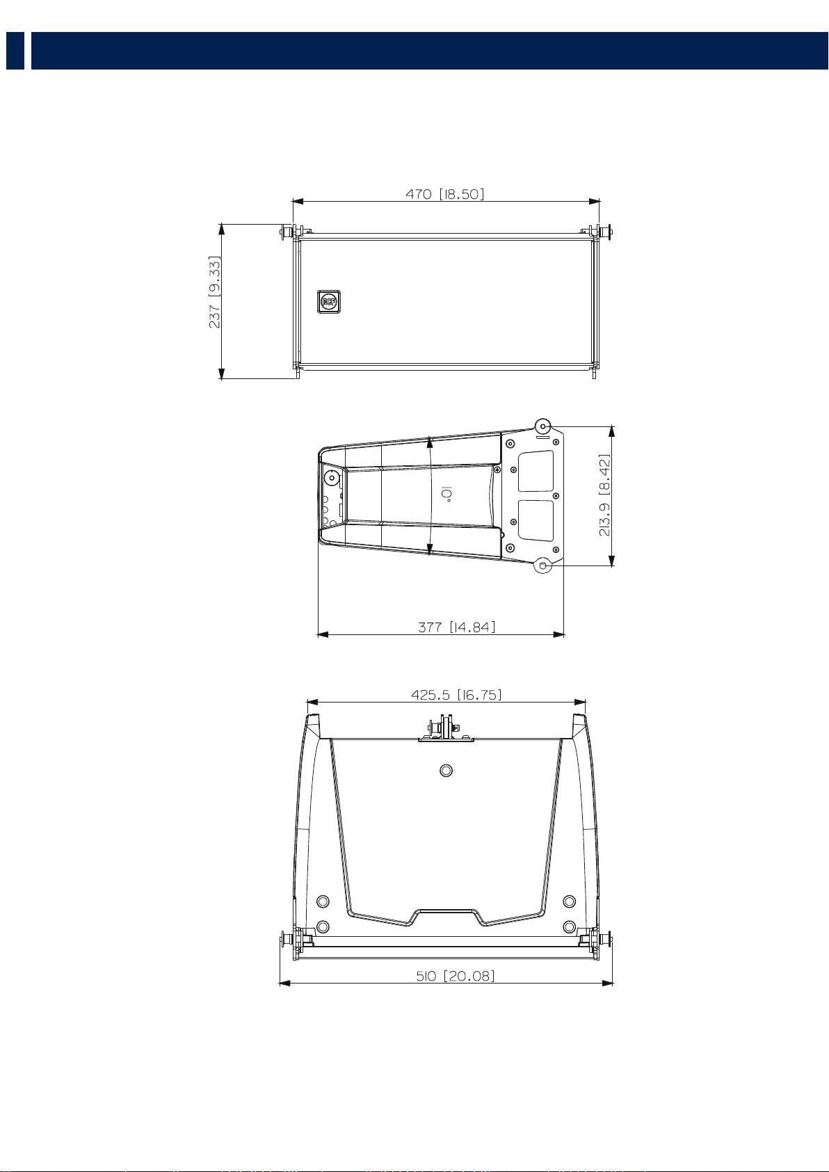
HL 6 DIMENSIONS
53
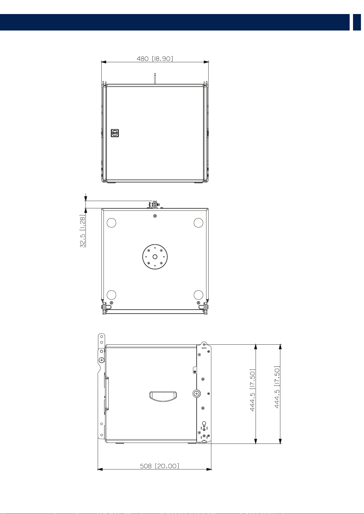
HL 35-S DIMENSIONS

54
EN
Acoustical specifications
Power section
Transducers
HL 6
Input/Output section
HL 35-S
Standard compliance
Physical specifications
Size
Shipping informations
Frequency Response (-10dB):
Max SPL @ 1m:
Horizontal coverage angle:
Vertical coverage angle:
Directivity index Q:
Nominal Impedance:
Power Handling:
Peak Power Handling:
Recommended Amplifier:
Protections:
Crossover Frequencies:
Compression Driver:
Nominal Impedance:
Input Power Rating:
Sensitivity:
Woofer:
Nominal Impedance:
Input Power Rating:
Sensitivity:
Input connectors:
Output connectors:
CE marking:
Cabinet/Case Material:
Hardware:
Handles:
Grille:
Color:
Height:
Width:
Depth:
Weight:
Package Height:
Package Width:
Package Depth:
Package Weight:
65 Hz ÷ 20000 Hz
131 dB
100°
10°
16
16 ohm
250 W RMS
1000 W PEAK
500 W
Dynamic Active Mosfet
900
1 x 1.0'' neo, 1.75'' v.c
16 ohm
50 W AES, 100 W PROGRAM POWER
109 dB, 1W @ 1m
2 x 6.0'' neo, 2.0'' v.c
200 W AES, 400 W PROGRAM POWER
16 ohm
92 dB, 1W @ 1m
Speakon
Speakon
Yes
PP Composite
Integrated array mechanics
2 on the rear panel
Steel
Black
237 mm / 9.33 inches
470 mm / 18.5 inches
377 mm / 14.84 inches
11 kg / 24.25 lbs
260 mm / 10.24 inches
550 mm / 21.65 inches
425 mm / 16.73 inches
12.4 kg / 27.34 lbs
40 Hz ÷ 140 Hz
134 dB
8 ohm
-
-
-
-
-
-
-
-
-
-
-
-
900 W
3600 W PEAK
1800 W
15'' neo, 4.0'' v.c
Yes
Speakon
Speakon
Baltic birch plywood
Integrated array mechanics
On side panels
Steel
Black
444.5 mm / 17.5 inches
480 mm / 18.9 inches
508 mm / 20 inches
28 kg / 61.73 lbs
530 mm / 20.87 inches
560 mm / 22.05 inches
525 mm / 20.67 inches
33 kg / 72.75 lbs
6. SPECIFICATIONS

55
EN

Tel +39 0522 274 411 - Fax +39 0522 232 428 - e-mail: info@rcf.it - www.rcf.it
RCF S.p.A. Via Raffaello Sanzio, 13 - 42124 Reggio Emilia - Italy
10307717 RevB