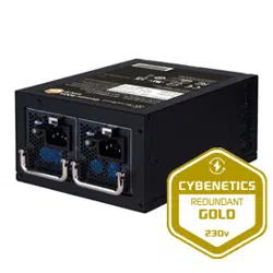

Gemini 900A Gold
Gemini Series
Cybenetics Gold 900W ATX Redundant Power Supply
▓
900W+900W 24hour and well working performance at 50°C fully continuous power output
▓
ATX form factor
▓
Cybenetics Gold Certification
▓
1+1 ATX redundant configuration
▓ All Japanese electrolytic capacitors
▓
Hot swappable design
▓
Convenient pull-out handle bars
Gemini 900A Gold
Gemini Series
SST-GM900A-GF / SST-GM900A-GFU
1+1 ATX Redundant Switching Power Supply
Cybenetics Gold efficiency certified.
900W+900W
The PS/2 redundant is a power sub-system made up of a cage and redundant, hot
swappable power supply modules. The cage is intended to be mounted in the
system and not redundant or hot swappable. The exterior face of the cage accepts
hot swappable power supply modules. The distribution board within the cage
distributes output power from the modules to a wire harness. Cooling fans, EMI
filtering, and IEC inlet connector(s) may be located in the modules.
The power supply modules shall incorporate universal power input with active
power factor correction, which shall reduce line harmonics in accordance with the
EN61000-3-2 and JEIDA MITI standards.
The AC input connector shall be an IEC 320 C-14 power inlet. This inlet is
rated for 10A/250 VAC.
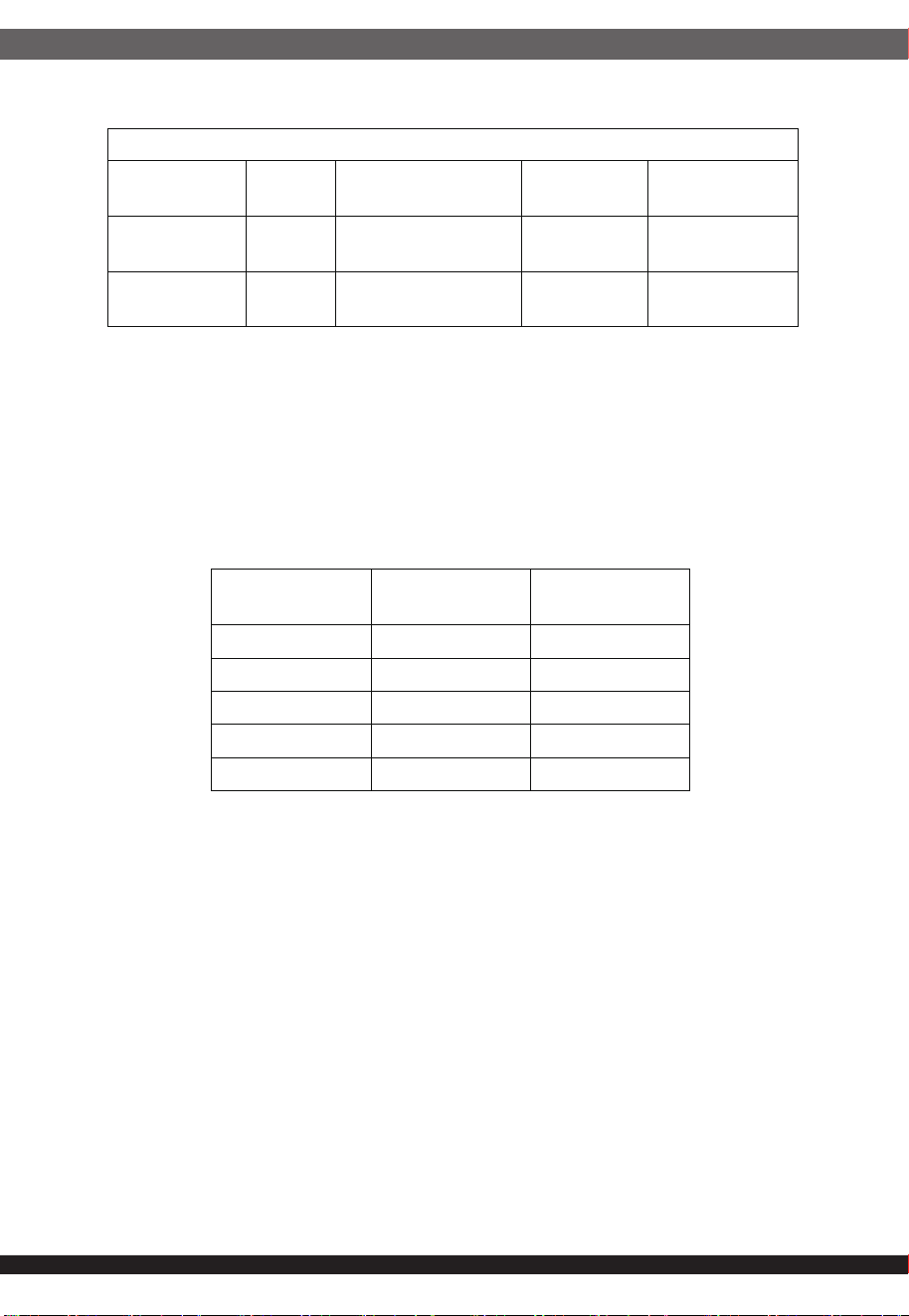
The power supply must operate within all specified limits over the following
input voltage range.
1.GENERAL DESCRIPTION AND SCOPE
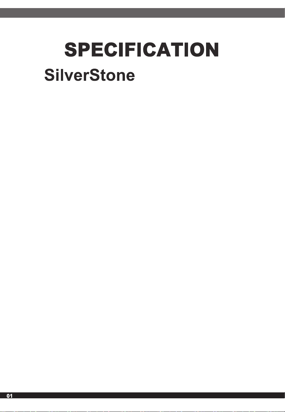
2.AC Input Requirements
2.1 AC Inlet Connector
2.2 AC Input Voltage Specification
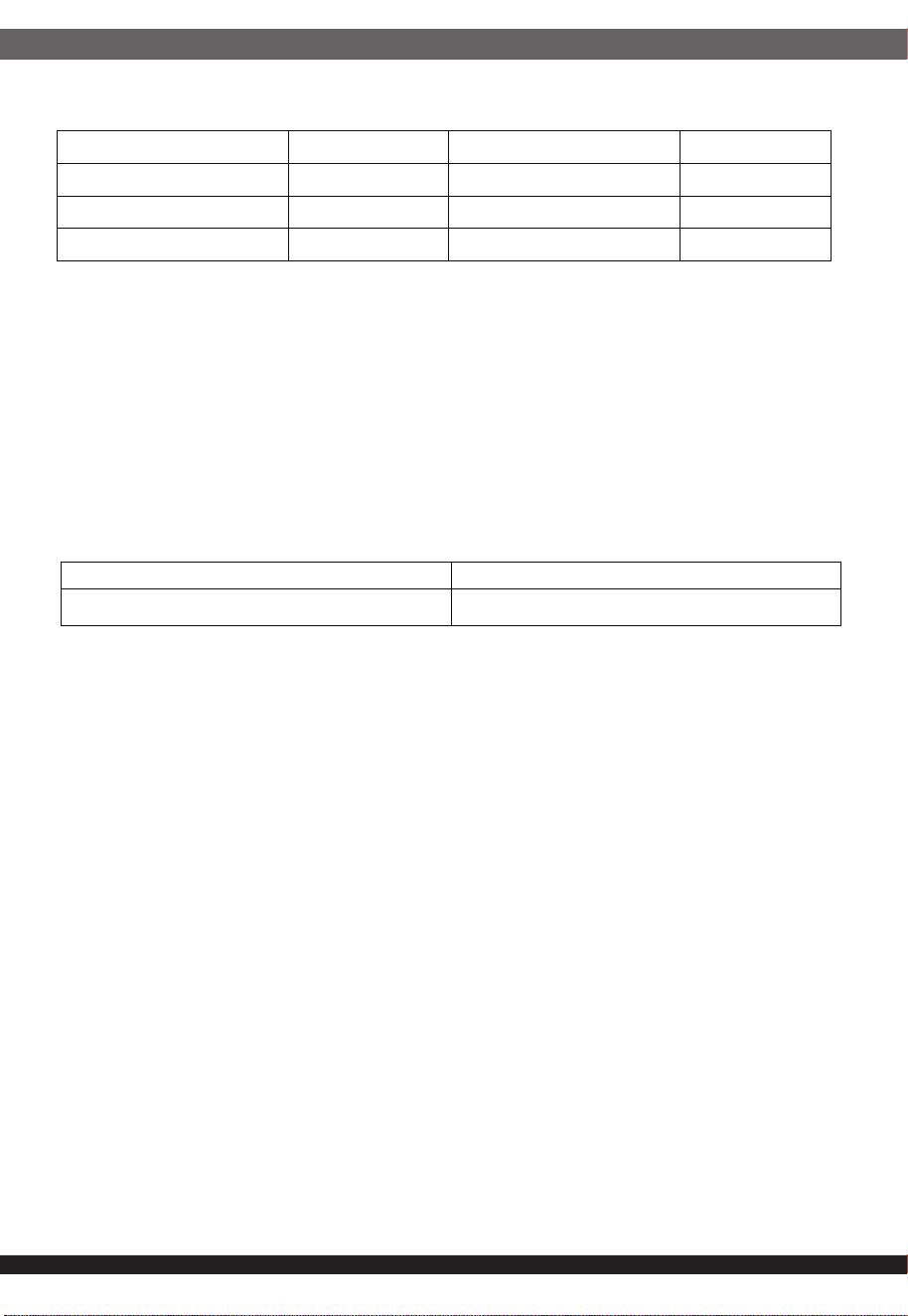
Table1: AC Input Rating
2.3 Power Factor
The power factor shall be greater than 0.95 at full load / 100 Vrms input
voltage conditions, and 0.9 at full load / 240Vrms input voltage conditions
2.4 Input Under Voltage
Brown-out( AC UVP)
The power supply shall power off if the AC input is below VAC low_limit and
shall start (auto recover) if VAC recover is reached. Input of VAC below VAC
recover shall not cause any damage to the power supply, including the input
fuse.
2.5 Hold-up Time
The power supply holdup time requirements to 80% of maximum load.
2.6 Efficiency
Efficiency shall be tested at AC input voltages of 115VAC and 230VAC. And
only insert one power module into the power cage. The voltage should measure
on the back plane. It could be support 80 Plus Gold efficiency
2.7 AC Line Dropout
An AC line dropout is defined to be when the AC input drops to 0 VAC at any
phase of the AC line for any length of time. During an AC dropout of one cycle
or less the power supply must meet dynamic voltage regulation requirements
up to 75% of the rated output load. An AC line dropout of one cycle or less shall
not cause any tripping of control signals or protection circuits. If the AC dropout
lasts longer than one cycle or the load is greater than 75%, the power supply
should recover and meet all turn on requirements. The power supply must meet
the AC dropout requirement over rated AC voltages, frequencies, and output
loading conditions. Any dropout of the AC line shall not cause damage to the
power supply. In the case of redundant AC inputs, the AC line dropout may
occur on either or both AC inlet.
ıij
PARAMETER MIN RATED MAX
Voltage (110) 90 100-127 Vrms 140 Vrms
Voltage (220) 180 200-240 Vrms 264 Vrms
Frequency 47 Hz
--
63 Hz
VAC
recover (Brown in)
VAC
low_limit (Brown out)
82VAC ±4VAC 75VAC ±5VAC
ıĴ
2.8 AC Line Fuse
2.9 AC Inrush
The power supply shall incorporate one input fuse on the LINE side for input
over-current protection to prevent damage to the power supply and meet
product safety requirements. Fuses should be slow blow type or equivalent to
prevent nuisance trips. AC inrush current shall not cause the AC line fuse to
blow under any conditions. All protection circuits in the power supply shall not
cause the AC fuse to blow unless a component in the power supply has failed.
This includes DC output load short conditions.
An additional inrush current limit is recommended for some system applications
that require multiple systems on a single AC circuit. Under all other conditions,
power supply should not be damaged.
(Cold start – 25 deg. C)
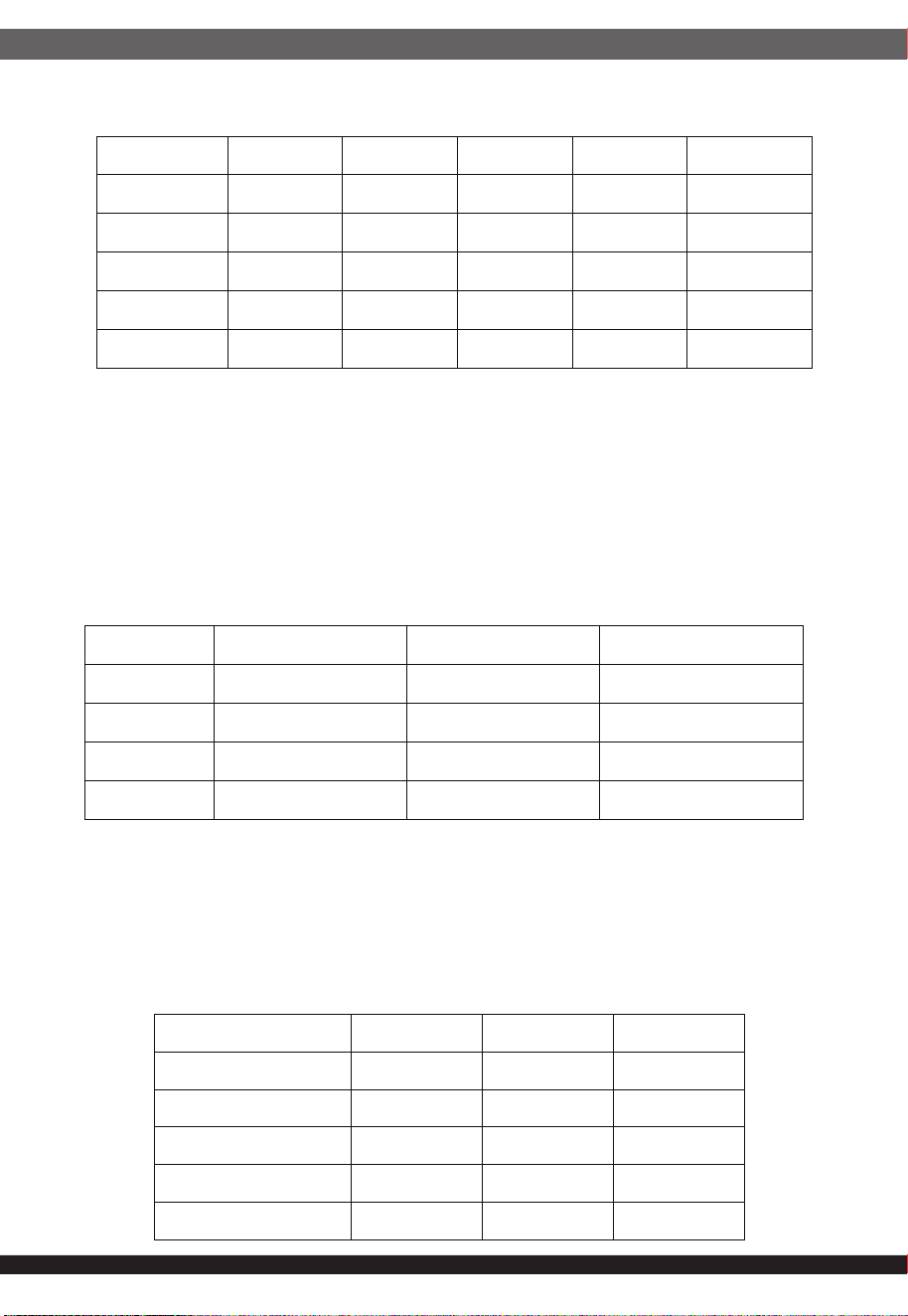
2.10 AC Line Transient Specification
Table 2: AC Line Sag Transient Performance
AC line transient conditions shall be defined as “sag” and “surge”
conditions. Sag conditions (also referred to as “brownout” conditions) will be
defined as the AC line voltage dropping below nominal voltage. Surge conditions
will be defined as the AC line voltage rising above nominal voltage.
The power supply shall meet the requirements under the following AC line sag
and surge conditions.
AC Line Sag
Duration Sag Operating AC Voltage Line Frequency Performance
Criteria
Continuous 10% Nominal AC Voltage
ranges
50/60 Hz No loss of
function or
performance
0 to 1 AC cycle 70% Nominal AC Voltage
ranges
50/60 Hz No loss of
function or
performance
>1 AC cycle >10% Nominal AC Voltage
ranges
50/60 Hz Loss of function
acceptable, self-
recoverable
115V 40A
230V 80A
3.1 Output Power/Currents
3.2 Voltage Regulation
The following tables define the power and current ratings for different
recommended power levels.
The power assembly output voltages must stay within the following voltage
limits when operating at steady state and dynamic loading conditions.
These limits include the peak-peak ripple/noise specified in Section 5.10.
All outputs are measured with reference to the return remote sense (ReturnS)
signal. The 5 V, 12V, –12 V, and 5 VSB outputs are measured at the power
assembly connectors referenced to ReturnS. The +3.3 V is measured at its
remote sense signal (3.3VS) located at the signal connector.
Table 3: AC Line Surge Transient Performance
AC Line Surge
Duration Surge Operating AC Voltage Line Frequency Performance
Criteria
Continuous 10% Nominal AC Voltages 50/60 Hz No loss of function
or performance
0 to ½ AC cycle 30% Mid-point of nominal
AC Voltages
50/60 Hz No loss of function
or performance
3.DC Output Specification
ıĵ
3.1.1 Standby Outputs
Table 4: 900 W Load Ratings
The 5 VSB output shall be present when an AC input greater than the
power supply turn on voltage is applied.
1. Maximum continuous total DC output power should not exceed 900 W.
2. Maximum continuous combined load on +3.3 VDC and +5 VDC outputs
shall not exceed 130 W
Voltage Minimum
Continuous
Maximum
Continuous
+3.3 V 0 A 20.0 A
+5 V 0 A 20.0 A
+12V 1A 75 A
-12 V 0 A 0.5A
+5 VSB 0 A 3 A
3.3 Dynamic Loading
Table 6: Voltage Regulation Limits
Table 9: Transient Load Requirements
Table 10: Capacitive Loading Conditions
The output voltages shall remain within the limits specified in Table 9 for the
step loading and within the limits specified in for the capacitive loading.
The load transient repetition rate shall be tested between 50 Hz and 5kHz at
duty cycles ranging from 10%-90%. The load transient repetition rate is only
a test specification. The step load may occur anywhere within the MIN load to
the MAX load shown in Table 7 and Table 8.
3.4 Capacitive Loading
The power supply shall be stable and meet all requirements, except dynamic
loading requirements, with the following capacitive loading ranges.
Note: Up to 10,000 μF of the +12V capacitive loading may be on the +12V output.
ıĶ
Parameter MIN NOM MAX Units Tolerance
+3.3 V +3.135 +3.30 +3.46
Vrms
+5/-5%
+5 V +4.75 +5.00 +5.25
Vrms
+5/-5%
+12V +11.40 +12.00 +12.60
Vrms
+5/-5%
-12 V -10.80 -12.00 -13.20
Vrms
+10/-10%
+5 VSB +4.75 +5.00 +5.25
Vrms
+5/-5%
Output
. Step Load Size
Load Slew Rate Capacitive Load
+3.3 V 20% of max load 0.5 A/μs 1000 μF
+5 V 20% of max load 0.5 A/μs 1000 μF
+12V 30% of max load 0.5 A/μs 6600 μF
+5 VSB 25% of max load 0.5 A/μs 1 μF
Output MIN MAX Units
+3.3 V 10 12,000 μF
+5 V 10 12,000 μF
+12 V 10 33,000 μF
-12 V 1 350 μF
+5 VSB 1 350 μF
ıķ
3.5 Ripple and Noise
3.6 Load sharing
Table 11: Ripple and Noise
3.7 Hot Swap Requirements
The +12 V output shall have active load sharing. When operating at 50%
of full load, the output current of any 1+1 power supplies shall be within
(+/-10%). For example, if power supply #1 is operating at 20A, then all other
power supplies within the system shall be operating between 18A to 22A
(+/- 10% of 20A)
The power supply modules shall be hot swappable. Hot swapping a power
supply is the process of inserting and extracting a power supply from an
operating power system. During this process the output voltages shall
remain within the limits specified in Table 6 with the capacitive load specified.
The hot swap test must be conducted when the sub-system is operating
under both static and dynamic conditions. The sub-system shall not exceed
the maximum inrush current as specified in Table 7 and Table 8. The power
supply can be hot swapped by the following methods:
AC connecting separately to each module. Up to two power supplies may be
on a single AC power source. Extraction: The AC power will be disconnected
from the power supply first and then the power supply is extracted from the
sub-system. This could occur in standby mode or powered on mode. Insertion:
The module is inserted into the cage and then AC power will be connected to
the power supply module.
For power modules with AC docking at the same time as DC. Extraction:
The module is extracted from the cage and both AC and DC disconnect at the
same time. This could occur in standby or power on mode. No damage or
arcing shall occur to the DC or AC contacts which could cause damage.
Insertion: The AC and DC connect at the same time as the module is inserted
into the cage. No damage to the connector contacts shall occur. The module
may power on or come up into standby mode.
Many variations of the above are possible. Supplies need to be compatible with
these different variations depending upon the sub-system construction.
In general, a failed (off by internal latch or external control) supply may be
removed, then replaced with a good power supply, however, hot swap needs
to work with operational as well as failed power supplies. The newly inserted
power supply may get turned on by inserting the supply into the system or by
system management recognizing an inserted supply and explicitly turning it on.
+3.3 V +5 V +12 V -12 V +5 VSB
50 mVp-p 50 mVp-p 120 mVp-p 200 mVp-p 50 mVp-p
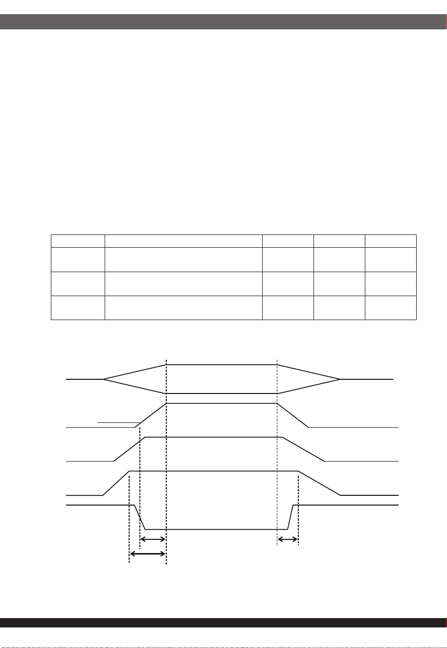
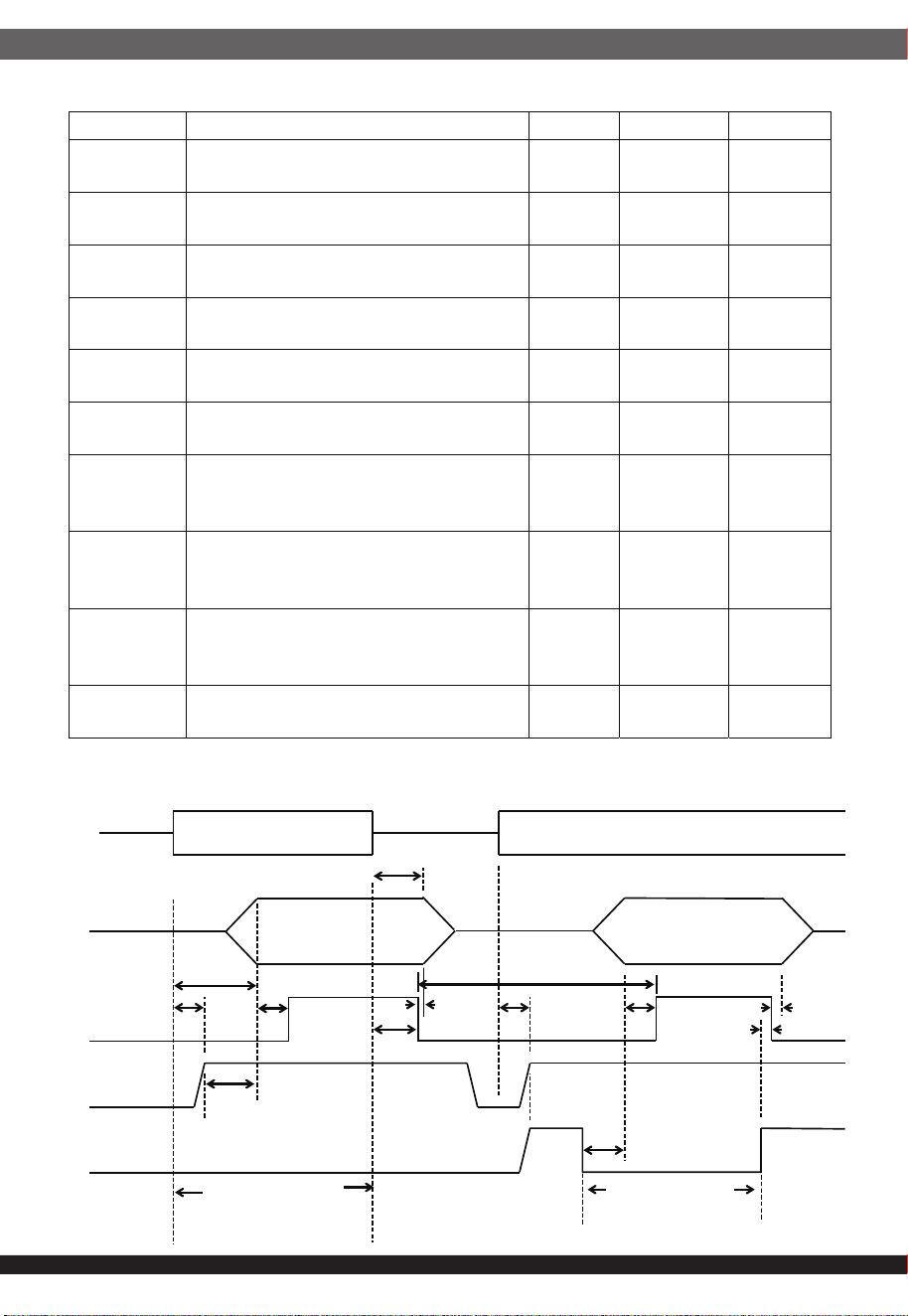
These are the timing requirements for the power supply operation.
The output voltages must rise from 10% to within regulation limits
(Tvout_rise) within 1 to 70ms. The +3.3V, +5V and +12V output voltages
should start to rise approximately at the same time. All outputs must rise
monotonically. Each output voltage shall reach regulation within 50ms
(Tvout_on) of each other during turn on of the power supply. Each output+
voltage shall fall out of regulation within 400msec (Tvout_off) of each other
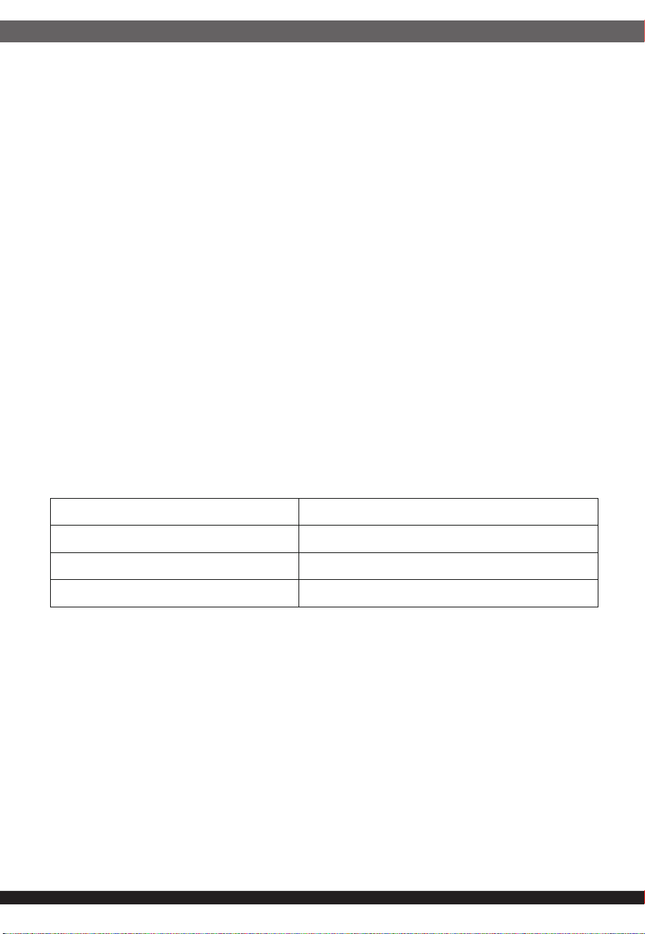
during turn off. Refer to Figure 1 Power Supply Timing. Figure 2
Turn-on Turn-off Timing shows the timing requirements for the power supply
being turned on and off via the AC input with PSON held low, and the
power supply being turned on and off with the PSON signal after AC input
is applied.
3.8 Timing Requirements
ıĸ
Table: 12 Output Voltage Timing
Figure 1: Power Supply Timing
ITEM DESCRIPTION MIN MAX UNITS
T
vout_rise
Output voltage rise time from each main
output.
1 70 msec
T
vout_on
All main outputs must be within
regulation of each other within this time.
50 msec
T
vout_off
All main outputs must leave regulation
within this time.
400 msec
Vo
10% Vout
T
vout rise
T
vout
_
on
T
vout_off
V1
V2
V3
V4
ıĹ
Table 13: Turn On/Turn Off Timing
AC Input Figure 3: Timing Diagram
ITEM DESCRIPTION MIN MAX UNIS
T
sb_on_delay
Delay from AC being applied to 5VSB
being within regulation.
3000 msec
T
ac_on_delay
Delay from AC being applied to all
output voltages being within regulation.
4500 msec
T
vout_holdup
Time all output voltages stay within
regulation after loss of AC.
17 msec
T
pwok_holdup
Delay from loss of AC to deassertion of
PWOK.
16 msec
T
pson_on_delay
Delay from PSON
#
active to output
voltages within regulation limits.
5 400 msec
T
pson_pwok
Delay from PSON
#
deactive to PWOK
being deasserted.
100 msec
T
pwok_on
Delay from output voltages within
regulation limits to PWOK asserted at
turn on.
100 500 msec
T
pwok_off
Delay from PWOK deasserted to output
voltages (3.3V, 5V, 12V) dropping out of
regulation limits.
1 msec
T
pwok_low
Duration of PWOK being in the
deasserted state during an off/on cycle
using AC or the PSON signal.
100 msec
T
sb_vout
Delay from 5VSB being in regulation to
O/Ps being in regulation at AC turn on.
50 1000 msec
Vout
PWOK
5VSB
PSON
T
sb on dela
y
T
AC_on_delay
T
pwok_on
T
vout_holdup
T
pwok_holdup
T
pson on delay
T
sb on dela
y
T
pwok_on
T
pwok_off
T
pwok_off
T
pson_pwok
T
pwok
T
sb_vout
AC turn on/off
PSON turn
on/off cycle
Protection circuits inside the power supply shall cause only the power supply’s
main outputs to shutdown. If the power supply latches off due to a protection
circuit tripping, an AC cycle OFF for 15 s and a PSON# cycle HIGH for 1 s must
be able to reset the power supply.
4. Protection Circuits
4.1 Over Current Protection and Short Circuit Protection
4.2 Over Voltage Protection
Table 15: Over Current/Short Circuit Protection
The Over Current Condition shall be measured internal to the power supply
on all outputs (Main and Auxiliary OutputAR), and preventing outputs to
exceed current limits specified in below table. The power supply shall
shutdown and latch off after an Over Current condition on main outputs,
the auxiliary output shall be auto recover (VsBAR) after the OCP/SCP had
been removed.
The latch on the main output can be cleared by asserting PSON# signal or
by an Input Power interruption. The power supply shall alert the system of
the OCP/SCP condition via SMB Alert# and fail LED indicator.
The power supply shall not be damaged from repeated power cycling in
this condition.
The power supply over voltage protection shall be locally sensed in the hot
swap modules. The power supply shall shutdown and latch off after an over
voltage condition occurs. This latch shall be cleared by toggling the PSON#
signal or by an AC power interruption. Table 16 contains the over voltage
limits. The values are measured at the output of the power supply’s connectors.
The voltage shall never exceed the maximum levels when measured at the
power pins of the power supply connector during any single point of fail. The
voltage shall never trip any lower than the minimum levels when measured
at the power pins of the power supply connector.
ıĺ
Voltage Over Current Limit (Iout limit)
+3.3 V 24A---32A
+5 V 24A---32A
+12 V 83A---95A
4.3 Leakage current
4.4 Over Temperature Protection
4.5 Fan Failure Protection
IJı
The leakage current from AC to safety ground will not exceed 3.5 mA-rms at
264Vac, 50 Hz.
The power supply shall have a circuit internal to monitor the power supply
internal fan. The fan failure protection shall monitor the fan speed and should
assert SMBAlert# in case the fan Rotation Per Minute (RPM) drop lower
threshold or set PWM Δ as defined in below table.
The protection circuit shall shutoff the main outputs only and let them auto
recover when the fan failure had been cleared.
Table 16: Over Voltage Limits
The power supply shall have minimum of two thermal sensors to measure the
environmental (Tenv) and critical component (Tcomp) temperature. The thermal
sensors shall be part of a protection circuit to protected against overtemperature
conditions caused by loss of fan cooling or excessive ambient temperature.
In an critical Over temperature condition, specified in below table, the PSU shall
be shutdown with the exception of the auxiliary output (VsBAR).
The Thermal CLST shall be part of the OTPAR.
The power supply shall alert the system of the OTPAR condition via SMBAlert#
and fail LED indicator. The power supply will auto recover from this condition,
when the temperature is dropping within specification again. If the OTPAR is
caused due to a defective fan, the power supply shall latch off and not auto
recover.
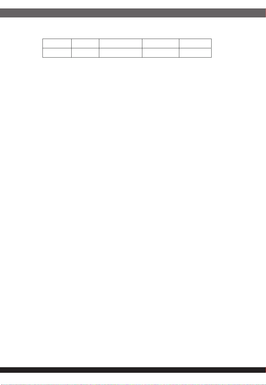
Table 17: Over Temperature ProtectionAR
The thermal sensors shall have an accuracy of max. 1°C per step and a
tolerance of ± 2%.Ambient temperature: 50°C
Output Voltage MIN (V) MAX (V)
+3.3 V 3.5 4.5
+5 V 5.5 6.82
+12V 13.4 15.6
Condition Warning in °C Critical in°C Timing for
SMBAlert
#
/LED
Tenv 75 80 1msec
Table 18: Fan Failure Protection
4.6 Over Power Protection
4.7 Under Voltage Protection
The power supply must protect itself by Over Power Protection, no any
components damaged.
The power supply shall shutdown and latch off after an under voltage
condition occurs. This latch shall be cleared by toggling the PSON# signal
or by an AC power interruption. Table 18.1 contains the under voltage limits.
Table 18.1: Under Voltage Limits
The following sections define the input and output signals from the power supply.
Signals that can be defined as low true use the following convention:
signal# = low true
5.1 PSON#
The PSON# signal is required to remotely turn on/off the power supply. PSON#
is an active low signal that turns on the +3.3 V, +5 V, +12 V, and -12 V power
rails. When this signal is not pulled low by the system, or left open, the outputs
(except the +5 VSB and Vbias) turn off. This signal is pulled to a standby voltage
by a pull-up resistor internal to the power supply. Refer to Figure 2 for timing
diagram.
5.Control and Indicator Functions
IJIJ
Condition FAN RPM Timing for LED
Warning 1500 20sec
Critical 1500 30sec
Output Voltage MIN (V) MAX (V)
+3.3V 2.5 3.0
+5V 3.9 4.6
+12V 8.5 10.9
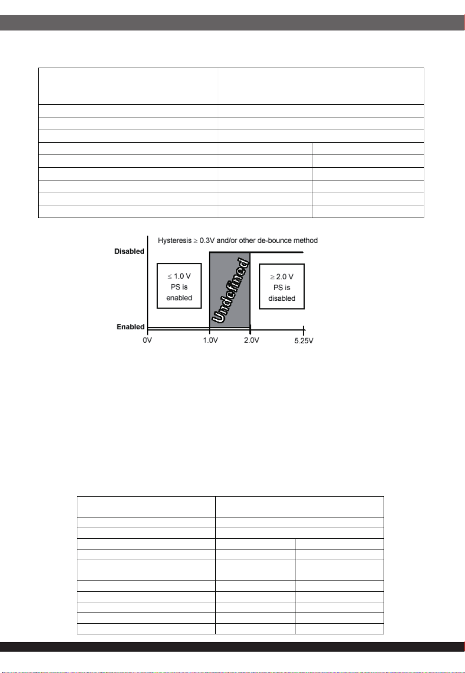
Table 19: PSON# Signal Characteristic
Signal Type
Accepts an open collector/drain input from the
system. Pull-up to VSB located in power
supply.
PSON
#
= Low, PSKILL = Low
ON
PSON
#
= Open, PSKILL = Low or Open
OFF
PSON
#
= Low, PSKILL = Open
OFF
MIN MAX
Logic level low (power supply ON)
0V 0.8V
Logic level high (power supply OFF)
2.0V 5.25V
Source current, Vpson = low
4mA
Power up delay: T
pson_on_delay
5msec 400msec
PWOK delay: T
pson_pwok
50msec
IJij
5.2 PWOK (Power OK)
Table 20: PWOK Signal Characteristics
PWOK is a power OK signal and will be pulled HIGH by the power supply to
indicate that all the outputs are within the regulation limits of the power supply.
When any output voltage falls below regulation limits or when AC power has
been removed for a time sufficiently long so that power supply operation is no
longer guaranteed, PWOK will be pull to a LOW state. See Figure 2 for a
representation of the timing characteristics of PWOK. The start of the PWOK
delay time shall be inhibited as long as any power supply output is in current
limit.
Signal Type
Open collector/drain output from power supply.
Pull-up to VSB located in power supply.
PWOK = High
Power OK
PWOK = Low
Power Not OK
MIN MAX
Logic level low voltage, Isink=4mA
0V 0.4V
Logic level high voltage,
Isource=200
A
2.4V 5.25V
Sink current, PWOK = low
4mA
Source current, PWOK = high
2mA
PWOK delay: T
pwok_on
100ms 500ms
PWOK rise and fall time
100sec
Power down delay: T
pwok_off
1ms 200msec
5.3 Power Supply LED Indicators
IJĴ
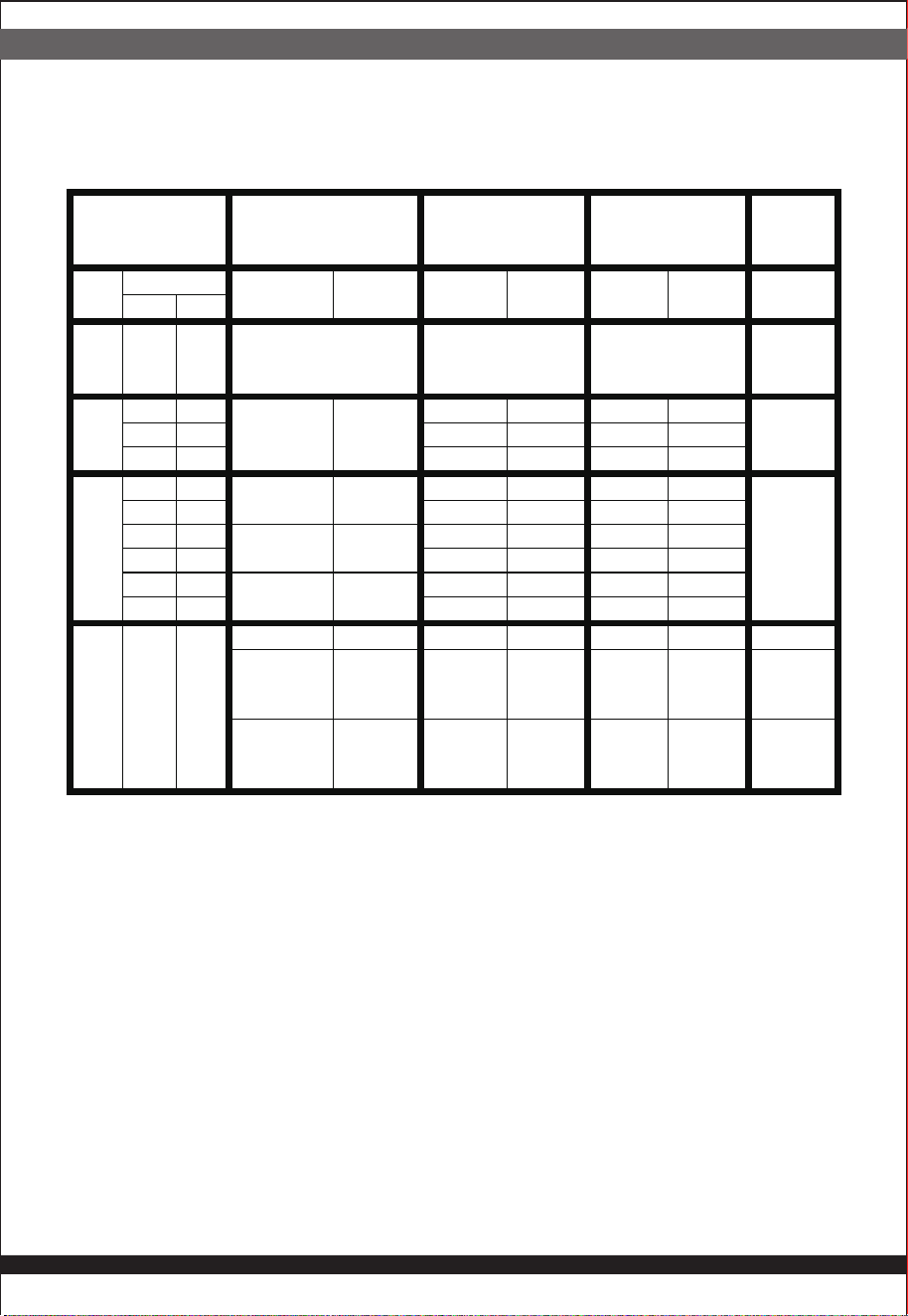
There will be a single bi-color LED to indicate power supply status. Refer to
Table 21 LED Indicators for conditions of the LED.
Table 21: LED and buzzer control rules
The LED shall be visible on the power supply’s exterior face. LED shall be
securely mounted in such a way that incidental pressure on the LED shall not
cause it to become displaced.
5.4 Alarm Sound (RESET BUTTON)
This is an alarm to report the one of the single module is fail in redundant
mode. It will be to sound the alarm till the PGIB signal is recovery or push
the RESET button.
CONDITION STATUS MODULE1(M1)
LIGHT
CONDITION
MODULE2(M2)
LIGHT
CONDITION
BUZZER
(ON
CAGE)
PS-
ON
AC-OK Failure Warning Green
LED
Red
LED
Green
LED
Red
LED
M1 M2
ON
YES
YES
Module
Identification.
Green and Red
led blink
Alternately.
Green and Red
led blink
alternately.
OFF
OFF
YES NO
NIL
NIL
Blinking OFF OFF Blinking
OFF
NO YES OFF Blinking Blinking OFF
YES YES Blinking OFF Blinking OFF
ON
YES NO YES YES OFF ON OFF ON
ON
NO YES OFF ON OFF ON
YES NO NO YES Blinking Blinking Blinking Blinking
NO YES Blinking Blinking Blinking Blinking
YES NO NO NO ON OFF OFF Blinking
NO YES OFF Blinking ON OFF
ON
YES
YES
NO NO ON OFF ON OFF OFF
NO
YES
OFF Blinking
when
warning
OFF
Blinking
when
warning
OFF
YES
YES
OFF
ON
when
failure
OFF
ON
when
failure
ON

IJĵ
MTBF>100,000 Hrs at 25°C, nominal input.
1.This software support SST-GM900A-GF and SST-GM900A-GFU PSU only.
2.The software has been tested and could be using on the below Microsoft
Windows system.
• Microsoft Windows 7
• Microsoft Windows 10
• Microsoft Windows 11
3.We used the compression software to collect the all tool. Therefore, please
make sure your system has been install the compression software when you
using our monitor software.
4.Our monitor software has two version, which included 32 bit software and 64 bit
software. Please follow your original operation system to install the right version
of monitor software.
7.1 Temperature Requirements
The operation ambient temperature shall be 0°C to 50°C.
The non-operation ambient temperature shall be -20°C to 80°C.
7.2 Relative Humidity
Operating: 5% to 90 % relative humidity (non-condensing)
Non-operating: 5% to 90 % relative humidity(non-condensing)
The mechanical drawing of the subject power supply, which indicate the form factor,
location of The mounting holes, location, the length of the connectors, and other
physical specifications of the subject power supply. Please refer to the attachment
drawing
Dimensions: 150mm (W) × 86mm (H) × 190mm
6.MTBF
8. MECHANICAL SPECIFICATIONS
9. How to install the Gemini ATX redundant monitor software?
Before install the monitor software on your system, please check the
below point.
7. ENVIRONMENTAL REQUIREMENTS
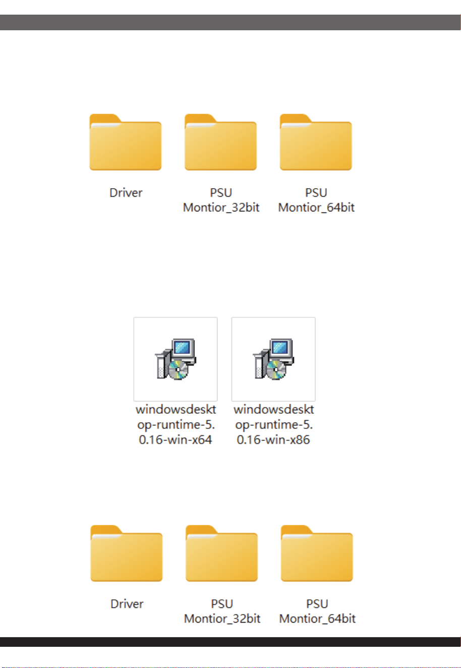
STEP1.
You will see the below three folders when you used compression software to
make the unzip all files.
Software install guideline
STEP 2
Please choose the Driver folder and you will see the two software as below.
Please follow your original operation system to install the right version of monitor
software. If your operation system is 32 bit, please install the x86 version. If your
operation system is 64 bit, please install the x64 version.
STEP 3
Please go back to the previos step and double clink the right PSU monitor.
If your operation system is 32 bit, please double clink the folder of PSU
Montior_32bit. If your operation system is 64 bit, please double clink the folder
of PSU Montior_64bit.
IJĶ
IJķ
STEP 4
Pleasae double clink the setup.exe file and follow the install step the install the
Silverstone Gemini ATX redundant PSU monitor. It will create the shortcut on
the desktop when you finish all install step.
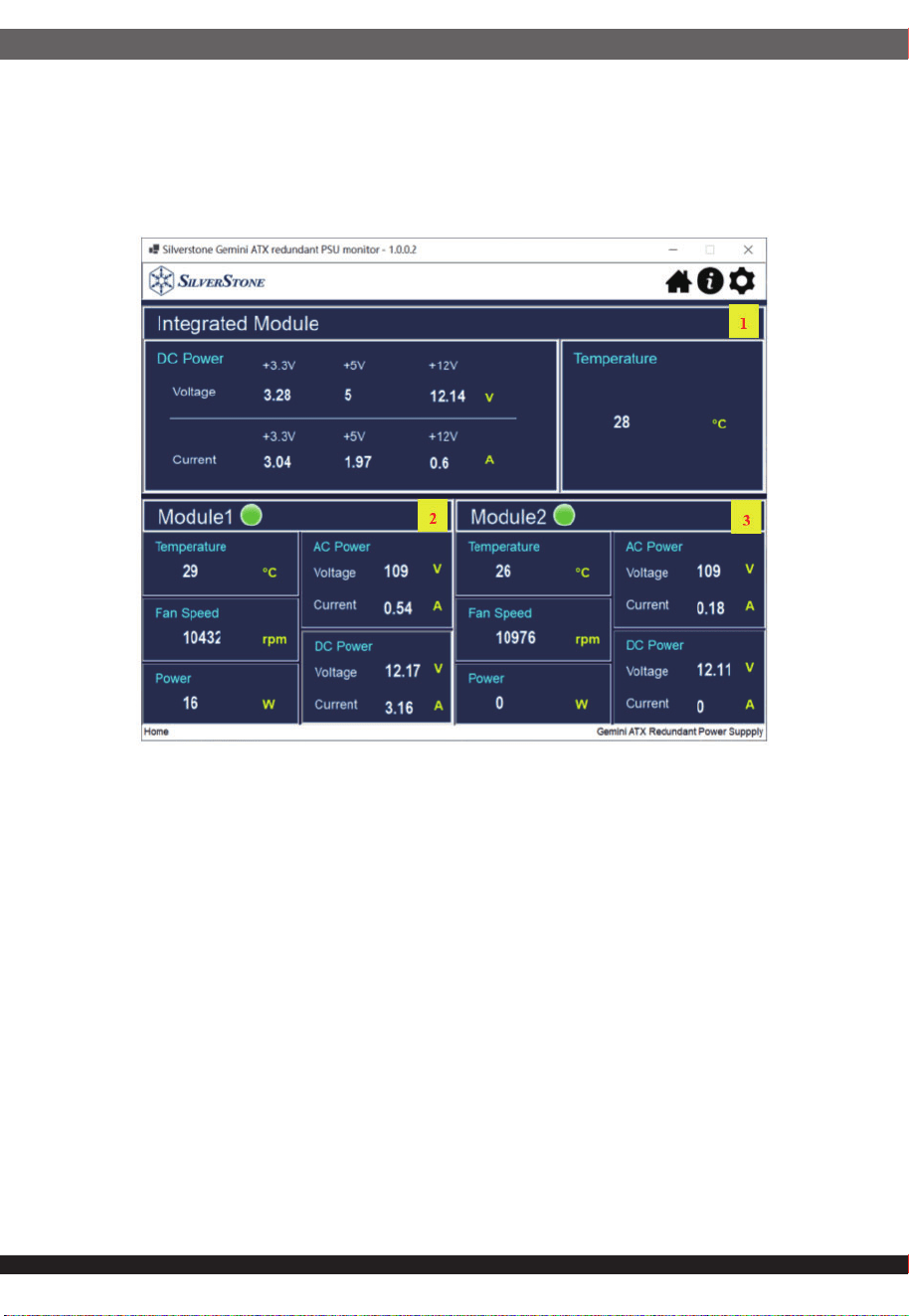
GUI Software
1. Display Integrated Module Power status
• +3.3V、+5V、+12V voltage and current
•Temperature
2. Display Module1 Power status
•Temperature (°C)
•Fan speed (RPM)
•Power output(W)
•Input voltage and current (AC Power)
•Output voltage and current (DC Power)
3. Display Module2 Power status
•Temperature (°C)
•Fan speed (RPM)
•Power output(W)
•Input voltage and current (AC Power)
•Output voltage and current (DC Power)
*Temperature warning: When the temperature exceeds the set temperature,
the temperature will be displayed in red, as shown in the figure.
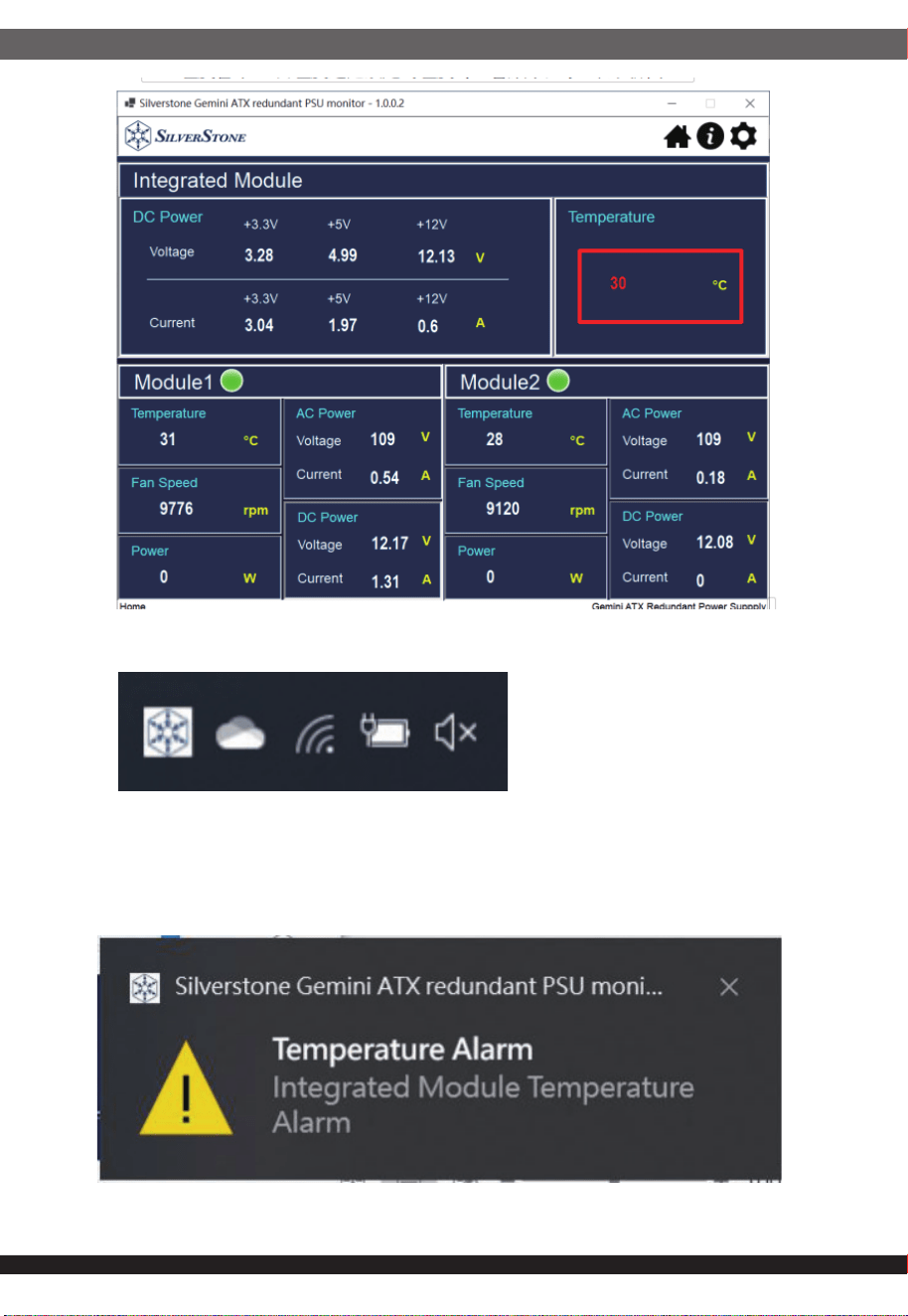
* When the progrram is minimized, it will be displayed in the toolbar
* When the program is minimized, the temperature warning will be
displayed as a notification, as shown in the figure below.
IJĸ
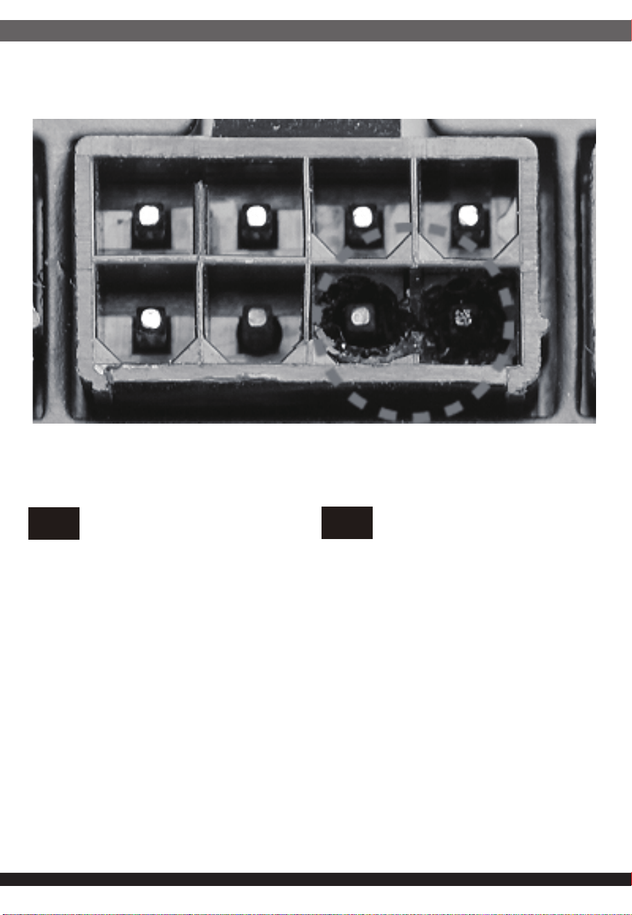
10. POWER SUPPLY CONNECTOR OVERUSE DEFINITION
Power supply connector overuse definition
EN
A single PCIe 8pin cable and connector’s maximum current rating is
12.5A, which is 150W (+12V x 12.5A). So SilverStone’s warranty will not
cover damages or malfunction resulting from the use of a graphics card
or expansion card with a single PCIe 8pin connector that exceeds
standard 225W total power draw (150W from PCIe 8pin connector +
75W from PCIe motherboard slot). Similarly, a graphics card or
expansion card with dual PCIe 8pin connectors that exceed 375W total
power draw (300W from two PCIe 8pin connectors + 75W from PCIe
motherboard slot) will also not be covered under warranty.
Peripheral (molex) or SATA connector’s maximum current rating is 5A,
which is 60W (+12V x 5A) or 25W (+5V x 5A). Please ensure connected
devices are operating under these limits. SilverStone’s warranty will not
cover damages or malfunction resulting from usages exceeding these
connectors and their associated cables.
24pin motherboard connector’s maximum current rating for its dual
+12V metal pins are 5A each, which totals 120W (+12V x 5A x 2).
Please ensure +12V drawing devices connected to the motherboard are
operating under these limits. SilverStone’s warranty will not cover
damages or malfunction resulting from usages exceeding these
connectors and their associated cables.
Definition einer Überlastung des
Netzanschlusses
DE
Die maximale Stromstärke eines einzelnen 8-poligen PCIe-Kabels und
Anschlusses beträgt 12,5 A, was 150 W (+12 V x 12,5 A) entspricht.
Daher deckt die SilverStone-Garantie keine Schäden oder
Fehlfunktionen durch den Einsatz einer Grafikkarte oder Erweiterung-
skarte mit einem einzigen 8-poligen PCIe-Anschluss ab, die die
Standardleistungsaufnahme von insgesamt 225 W übersteigt (150 W
vom 8-poligen PCIe-Anschluss + 75 W vom PCIe-Motherboard-Steck-
platz). Ebenso wird die Verwendung einer Grafikkarte oder
Erweiterungskarte mit zwei 8-poligen PCIe-Anschlüssen, die eine
Leistungsaufnahme von insgesamt 375 übersteigen (300 W von den
beiden 8-poligen PCIe-Anschlüssen + 75 W vom PCIe-Mother-
board-Steckplatz) nicht durch die Garantie abgedeckt.
Der maximale Nennstrom von Peripherie- (Molex) oder SATA-An-
schluss beträgt 5 A, was 60 W (+12 V x 5 A) oder 25 W (+5 V x 5 A)
entspricht. Bitte achten Sie darauf, dass verbundene Geräte unter
diesen Grenzwerten arbeiten. Die Garantie von SilverStone deckt keine
Schäden oder Fehlfunktionen aufgrund einer Nutzung ab, die diese
Anschlüsse und ihre zugehörigen Kabel übersteigt.
Der maximale Nennstrom des 24-poligen Motherboard-Anschlusses für
seine dualen +12-V-Metallkontakte beträgt jeweils 5 A, was insgesamt
120 W (+12 V x 5 A x 2) ergibt. Bitte stellen Sie sicher, dass mit dem
Motherboard verbundene +12-V-Geräte unter diesen Grenzwerten
arbeiten. SilverStones Garantie deckt keine Schäden oder
Fehlfunktionen aufgrund einer Nutzung jenseits der Angaben dieser
Anschlüsse und ihrer zugehörigen Kabel ab.
IJĹ
Définition de l'utilisation excessive du
connecteur d'alimentation électrique
FR
Le courant nominal maximum d'un périphérique (Molex) ou d'un
connecteur SATA est de 5 A, ce qui correspond à 60 W (+12 V x 5 A)
ou 25 W (+5 V x 5 A). Veuillez vous assurer que les appareils
connectés fonctionnent dans ces limites. La garantie de SilverStone
ne couvre pas les dommages ou les dysfonctionnements résultant
d'utilisations dépassant ces connecteurs et leurs câbles associés.
Le courant nominal maximal des connecteurs 24 broches de la carte
mère pour ses doubles broches métalliques +12 V est de 5 A chacun,
ce qui représente au total 120 W (+12 V x 5 A x 2). Veuillez vous
assurer que les dispositifs de tension +12 V connectés à la carte mère
fonctionnent dans ces limites. La garantie de SilverStone ne couvre
pas les dommages ou les dysfonctionnements résultant d'utilisations
dépassant la capacité de ces connecteurs et de leurs câbles
associés.
Le courant nominal maximum d'un câble et d'un connecteur PCIe 8
broches unique est de 12,5 A, ce qui correspond à 150 W (+12 V x
12,5 A). La garantie de SilverStone ne couvre donc pas les dommages
ou les dysfonctionnements résultant de l'utilisation d'une carte
graphique ou d'une carte d'extension avec un connecteur PCIe 8
broches unique qui dépasse une consommation énergétique totale de
225 W standard (150 W provenant du connecteur PCIe 8 broches + 75
W provenant de l'emplacement de la carte mère PCIe). De même, une
carte graphique ou une carte d'extension avec deux connecteurs PCIe
8 broches qui dépasse une consommation énergétique totale de 375 W
(300 W provenant des deux connecteurs PCIe 8 broches + 75 W
provenant de l'emplacement de la carte mère PCIe) ne sera également
pas couverte dans le cadre de la garantie.
La corrente massima di un singolo cavo PCIe a 8 pin e del connettore
è 12,5 A, corrispondente a 150 W (+12 V x 12,5 A). Pertanto, la
garanzia di SilverStone non copre danni o malfunzionamenti derivanti
dall'utilizzo di una scheda grafica o una scheda di espansione con un
singolo connettore PCIe a 8 pin che supera l'assorbimento totale di
225 W (150 W da connettore PCIe a 8 pin + 75 W da slot PCIe).
Analogamente, la garanzia non copre anche una scheda grafica o
una scheda di espansione con doppi connettori PCIe a 8 pin che
superano l'assorbimento totale di 375 W (300 W da doppi connettori
PCIe a 8 pin + 75 W dalla scheda madre PCIe).
La corrente massima del connettore periferico (molex) o SATA è 5 A,
corrispondente a 60 W (+12 V x 5 A) o 25 W (+5 V x 5 A). Assicurarsi
che i dispositivi collegati funzionino entro questi limiti. La garanzia di
SilverStone non copre danni o malfunzionamenti derivanti da uso
eccessivo di questi connettori e dei relativi cavi.
La corrente massima del connettore a 24 pin per scheda madre per i
suoi due pin di metallo a +12 V è di 5 A ciascuno, per un totale di 120
W (+12 V x 5 A x 2). Assicurarsi che i dispositivi a +12 V collegati alla
scheda madre funzionino con questi limiti. La garanzia di SilverStone
non copre danni o malfunzionamenti derivanti da uso eccessivo di
questi connettori e dei relativi cavi.
Definizione di uso eccessivo del connettore
di alimentazione
IT
La corriente máxima de un solo cable PCIe de 8 pines es 12,5A, lo
que son 150W (+12V x 12,5A). Por tanto, la garantía de SilverStone
no cubrirá daños o fallos provocados por el uso de una tarjeta gráfica
o de expansión con un único conector PCIe de 8 pines que exceda el
total estándar de 225W (150W del conector PCIe de 8 pines + 75W
del zócalo PCIe de la placa base). De igual modo, una tarjeta gráfica
o de expansión con conectores duales PCIe de 8 pines que superen
375W de potencia (300W de los dos conectores PCIe de 8 pines +
75W del zócalo de la placa base) tampoco será cubierta por la
garantía.
La corriente máxima del conector de periféricos (molex) o SATA es
5A, que son 60W (+12V x 5A) o 25W (+5V x 5A). Por favor,
asegúrese de que los dispositivos conectados funcionan dentro de
estos límites. La garantía de SilverStone no cubrirá daños o fallos a
resultas de un uso excesivo de estos conectores y sus cables
asociados.
La corriente máxima del conector de 24 pines de la placa base para
sus pines de metal duales de +12V es de 5A cada uno, para un total
de 120W (+12V x 5A x 2). Por favor, asegúrese de que los
dispositivos de +12V conectados a la placa base funcionan dentro de
estos límites. La garantía de SilverStone no cubrirá daños o averías a
resultas de un uso excesivo para estos conectores y sus cables
asociados.
Definición de uso excesivo del conector de
la Fuente de alimentación
ES
Определение чрезмерной нагрузки на
коннектор блока питания
RU
Один кабель и коннектор PCIe 8pin поддерживает ток 12.5A, что
равно 150Вт (+12В x 12.5A). Таким образом, гарантийные
обязательства SilverStone не будут действовать если вы
используете видеокарту или другую карту расширения с одним
коннектором PCIe 8pin, которые превышает стандартную общую
потребляемую мощность 225Вт (150Вт через коннектор PCIe 8pin +
75Вт через слот PCIe материнской платы). Аналогично, видеокарта
или другая карта расширения с
двумя коннекторами PCIe 8pin,
которые превышают общую потребляемую мощность 375Вт (300Вт
через коннектор PCIe 8pin + 75Вт через слот PCIe материнской
платы), также не будут покрываться гарантией.
Максимальный номинальный ток периферийного (molex) или SATA
разъёма составляет 5A, что равно 60Вт (+12В x 5A) или 25Вт (+5В x
5A). Пожалуйста, убедитесь, что подключенные устройства
работают в этих пределах. Гарантия SilverStone не будет
распространяться на неисправности,
возникающие в результате
использования этих коннекторов или подключаемых к ним кабелей.
Максимальный номинальный ток 24pin коннектора материнской
платы для его двойных металлических контактов +12В составляет
5A на каждый, что равно 120Вт (+12В x 5A x 2). Пожалуйста,
убедитесь, что устройства, подключенные к линии +12В, работают
в этих пределах. Гарантия SilverStone не будет распространяться
на неисправности, возникающие в
результате использования этих
коннекторов или подключаемых к ним кабелей.
전원 공급 커넥터 과용 정의
KR
埮沂穢ʹͺΖ穆理決挚愕珪嘫瘶汞牢堆洊幞洛冯汆Ͳ嵢昢
洊崫求嵢筞斶穞彺Έ·ΩͲ沋城埪΄ΚΝΧΖΣ΄ΥΠΟΖ汞
懺溣櫖昢垚祢渆Έ汞爣暒捊洊崫ʹͺΖ穆珪嘫瘶汞Έ歆
ʹͺΖ彚汾懺姢枲嵵汞Έ汞穯汊爎刂穞垚埮沂ʹͺΖ穆珪嘫瘶
痗沲勾岞穃獺姢喞筛沫獺姢庂斲殯穞櫲愢旣穞垚暖旇嬖垚
欪沗壟汊懺旇穞滆橐枻城埪決歆廎焲儆滆嵢Έ汞爣暒捊
洊崫ʹͺΖ穆珪嘫瘶儢汞Έ歆ʹͺΖ彚汾懺姢枲嵵汞Έ汞
穯汊爎刂穞垚姆櫂ʹͺΖ穆珪嘫瘶痗沲勾岞穃獺姢喞筛沫獺姢庂
斲殯空壊懺溣櫖昢懺旇空渂滆橐枻城埪
渂懆沫獞ΞΠΝΖΩ嬖垚΄Ͳ΅Ͳ珪嘫瘶汞牢堆洊幞洛冯汆Ͳ嵢昢
洊崫求嵢筞斶穞彺Έ·ΩͲ嬖垚Έ·ΩͲ沋城埪
櫶冶夢沫獞姪汆決峲穢洢穢穞櫖昢廒沗壟柢琢檂穯城埪΄ΚΝΧΖΣ΄ΥΠΟΖ
汞懺溣櫖昢垚決峲穢珪嘫瘶愕決歆櫶冶夞垚理決挚汞洛冯汊
爎刂穞櫲斲殯穮求嵢桮愢旣穞垚暖旇決喞欪沗壟汊懺旇穞滆
橐枻城埪
姆櫂·匎暓穆櫖斲殯夞垚穆彚汾懺姢珪嘫瘶汞洛冯洊幞垚
Ͳ決彶儇儇穯凊儆Έ·ΩͲΩ沋城埪彚汾懺姢櫖
櫶冶夢·沫獞儆空埿穢凊惾廒求嵢沗壟夞壊嵣穞柳柢欪
΄ΚΝΧΖΣ΄ΥΠΟΖ汆決珪嘫瘶喞分崮理決挚汞穢凊庂爎刂空昢
斲殯穮求嵢桮愢旣穞垚暖旇決喞処沫櫖堆空昢懺沫穞滆橐枻城埪
IJĺ
電力供給コネクタの使用限度超過に関する説明
JP
単一のPCIe8ピンケーブルおよびコネクタの最大定格電流は12.5Aで
150W(+12Vx12.5A)となります。それで定格225W合計電力消費(PCIe8
ピンコネクタからの150W+PCIeマザーボードスロットからの75W)を超
える、単一PCIe8ピンコネクタ装備のグラフィックスカードまたは拡張カ
ード使用によって生じた損傷や故障の場合、SilverStoneの製品保証は適
用外となります。同様に、375W合計電力消費(2基のPCIe8ピンコネクタ
からの300W+PCIeマザーボードスロットからの75W)を超える、デュア
ルPCIe8ピンコネクタ装備のグラフィックスカードまたは拡張カード使用
によって生じた損傷や故障の場合も、製品保証適用外となります。
周辺用(molex)またはSATAコネクタの最大定格電流は5Aで、60W
(+12Vx5A)または25W(+5Vx5A)となります。接続された装置がこれら
限度以内で動作することを確認してください。これらコネクタおよび関連
ケーブルの定格を超える使用法で生じた損傷や故障については、
SilverStone製品保証対象外となりますのでご注意ください。
24ピンマザーボードコネクタのデュアル+12V金属製ピンに対する最大
定格電流はそれぞれ5Aなので合計は120W(+12Vx5Ax2)となります。
接続される+12V入力のデバイスが、これら上限以内で動作することをご
確認ください。これらコネクタおよび関連ケーブルでの限界を超えた使
用で生じた損傷または故障は、SilverStoneによる製品保証対象外となり
ます。
ᴵ3&,HSLQ⬉⑤㒓Ϣ༈ⱘ᳔乱ᅮ⬉⌕Ў$ˈ⪺⡍᭄:
˄9[$˅DŽℸˈ䫊ⱘ⬉⑤ֱϡࣙᣀ⫼Ѣᴵ3&,H
SLQ༈Пᰒᠽܙˈ䍙䖛ޚ:ᘏࡳ㗫㣗ೈ᠔䗴៤ⱘᤳണ
ᬙ䱰˄:ⱘ3&,HSLQ༈:ⱘЏᵓ3&,Hᦦῑ˅DŽҹℸ㉏
ˈ㢹ঠ3&,HSLQ༈ⱘᰒᠽܙˈ䋳䕑ϔԚ䍙䖛:ᘏ
ࡳ㗫ˈ㾚ৠϡሲֱ㣗ೈݙ˄:ᴹ㞾ϸϾ3&,HSLQ༈:ⱘ
Џᵓ3&,Hᦦῑ˅DŽ
SLQ˄PROH[˅6$7$༈ⱘ᳔乱ᅮ⬉⌕Ў$ˈ:˄9[
$˅:˄9[$˅DŽ䇋⹂ֱ䖲ⱘ䆒ⱚԢѢℸ䰤ࠊϟ䖤㸠
DŽ
䫊ϡֱ䍙ߎ⬉⑤կᑨ఼༈ঞ݊Ⳍ݇㒓ᴤПՓ⫼䋳䕑Ϟ䰤᠔䗴
៤ⱘᤳണᬙ䱰DŽ
SLQЏᵓ༈ⱘঠ9䞥ሲ䩜㛮᳔乱ᅮ⬉⌕Ў$ˈ:˄
9[$[˅DŽ䇋⹂ֱ䖲ⱘ9䆒ⱚԢѢℸ䰤ࠊϟ䖤㸠DŽ
䫊ϡֱ䍙ߎ⬉⑤կᑨ఼༈ঞ݊Ⳍ݇㒓ᴤПՓ⫼䋳䕑Ϟ䰤᠔䗴
៤ⱘᤳണᬙ䱰DŽ
⬉⑤կᑨ఼༈䖛ᑺՓ⫼ᅮН
CN
䳏⑤կឝ఼丁䘢ᑺՓ⫼ᅮ㕽
TW
ஂṱ3&,HSLQ䳏⑤㎮㟛丁ⱘ᳔両ᅮ䳏⌕⚎$ˈ⪺⡍ᭌ:
˄9[$˅DŽℸˈ䡔ⱘ䳏⑤ֱϡࣙᣀ⫼ᮐஂṱ3&,H
SLQ丁П乃ܙˈ䍙䘢῭⑪:㐑ࡳ㗫㆘ೡ᠔䗴៤ⱘ᧡າ
ᬙ䱰˄:ⱘ3&,HSLQ丁:ⱘЏ″ᵓ3&,Hᦦῑ˅DŽҹℸ
串ˈ㢹٭䲭3&,HSLQ丁ⱘ乃ܙˈ䉴䓝ϔԚ䍙䘢:
㐑ࡳ㗫ˈ㽪ৠϡቀֱ㆘ೡܻ˄:՚㞾ܽן3&,HSLQ丁:
ⱘЏ″ᵓ3&,Hᦦῑ˅DŽ
SLQ˄PROH[˅6$7$丁ⱘ᳔両ᅮ䳏⌕⚎$ˈ:˄9[
$˅:˄9[$˅DŽ䂟⺎ֱ䗷ⱘ䀁٭ⱚԢᮐℸ䰤ࠊϟ䘟㸠
DŽ
䡔ϡֱ䍙ߎ䳏⑤կឝ఼丁ঞ݊Ⳍ䮰㎮ᴤПՓ⫼䉴䓝Ϟ䰤᠔䗴
៤ⱘ᧡າᬙ䱰DŽ
SLQЏ″ᵓ丁ⱘ䲭9䞥ቀ䞱㝇᳔両ᅮ䳏⌕⚎$ˈ:˄
9[$[˅DŽ䂟⺎ֱ䗷ⱘ9䀁٭ⱚԢᮐℸ䰤ࠊϟ䘟㸠DŽ
䡔ϡֱ䍙ߎ䳏⑤կឝ఼丁ঞ݊Ⳍ䮰㎮ᴤПՓ⫼䉴䓝Ϟ䰤᠔䗴
៤ⱘ᧡າᬙ䱰DŽ
ขีดจำกัดการรองรับการใช้งานของขั้วต่อจากพาวเวอร์ซัพพลาย
TH
สำหรับขั้วเชื่อมต่อและสายไฟเลี้ยง PCIe 8 พินสามารถรองรับกระแสได้สูงสุด 12.5
แอมป์หรือหมายถึง 150 วัตต์
(+12V x 12.5A) ดังนั้นการรับประกันจากทาง SilverStone จะไม่ครอบคลุมถึงความ
เสียหายหรือความผิดปรกติซึ่งเกิดขึ้นกับกราฟิกการ์ดรวมถึงการ์ดขยายความยาวที่ใช้งาน
ขั้วเชื่อมต่อ PCIe 8 พิน ซึ่งมันมีการใช้พลังงานรวมทั้งสิ้นเกินกว่ามาตรฐานที่กำหนดคือ
225 วัตต์ (150 วัตต์ จาก PCIe 8 พิน + 75 วัตต์ จากสล๊อต PCIe บน
เมนบอร์ด) อันรวมถึงกราฟิการ์ดหรือการ์ดขยายความยาวที่ใช้ขั้วต่อไฟเลี้ยง PCIe 8
พินจำนวน 2 ชุดซึ่งมีการใช้พลังงานทั้งสิ้น 375 วัตต์ (300 วัตต์ จากขั้ว PCIe 8
พิน 2 ชุด + 75 วัตต์ จากสล๊อต PCIe บนเมนบอร์ด) ซึ่งไม่ครอบคลุมเช่นกัน
ภายใต้การรับประกัน ขั้วเชื่อมต่อ Peripheral หรือ Molex 4 พินและ SATA มันสามารถ
รองรับกระแสได้สูงสุด 5 แอมป์หรือหมายถึง 60 วัตต์ (+12V x 5A) หรือ (+5V
+ 5A) กรุณาให้แน่ใจว่าอุปกรณ์ที่ใช้งานมีการใช้พลังงานไม่เกินกว่าขีดจำกัดที
่รองรับ ดัง
นั้นการรับประกันจากทาง SilverStone จะไม่ครอบคลุมถึงความเสียหายหรือความผิด
ปรกติจากอุปกรณ์ที่เชื่อมต่อใช้งานจากตัวสายเชื่อมต่อซึ่งมีการใช้พลังงานเกินกว่าขีด
จำกัด
กระแสไฟฟ้าสูงสุดของขั้วต่อเมนบอร์ด 24 พิน สำหรับพินโลหะ +12V คู่แต่ละอันมีค่า
5A ซึ่งรวมทั้งหมดเป็น 120W
(+12V x 5A x 2) โปรดตรวจสอบให้มั่นใจว่าอุปกรณ์ตัวดึงพลังงาน +12V ที่เชื่อม
ต่อกับเมนบอร์ดสามารถทำงานภายใต้ขีดจำกัดเหล่านี้ได้ การรับประกันของ SilverStone
ไม่คุ้มครองความเสียหาย หรืออาการเสียที่เป็นผลจากการใช้เกินขีดจำกัดของขั้วต่อและสาย
เคเบิลที่ใช้เชื่อมต่อเหล่านี้
ijı
警告:
1.
仅适用于海拔2000m及以下地区安全使用。
2. 本产品不得受水滴或水溅,设备上不应放置诸如花瓶一类的等装满液体的物品。
3. |类结构的设备应当连接到带保护接地连接的电网电源输出插座上。
4. 本产品以器具耦合器作为断开装置,在设备正常使用时要确保断开装置能方便触及到。
5. 在居住环境中,运行此设备可能会造成无线干扰
。
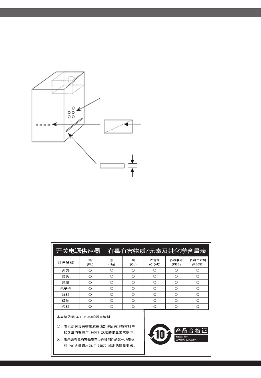
⚎њֱ䅋Փ⫼㗙ঞ䰆☿ⱘⳂⱘˈᅝ㺱ℸѸᓣ䳏⑤կឝ఼ᰖˈᖙ䷜ᅝ㺱ᮐヺড়ϟ߫䷙㽕∖ⱘ←Ёˈ
ϺϨᅝ㺱ཹᕠˈᠡৃϞ䳏⑤DŽ
←ᴤ䊾䷜⚎䰆☿←DŽᴤ䋼乏Ў䰆☿DŽ
←ⱘϞᮍঞو䙞П೧ᔶ䭟ᄨˈ᳔ܻᕥϡৃᮐPPDŽ
←ⱘϞᮍঞو䙞П䭋ṱൟ䭟ᄨˈᇡ㾦㎮䎱䲶ϡৃᮐPP˗㢹ᇀᑺᇣᮐPPˈࠛ䭋ᑺϡফ䰤ࠊDŽ
←ᑩ䚼ϡৃ᳝䭟ᄨDŽᑩ䚼ϡৃ᳝ᓔᄨDŽ
ⳈᕥϡᮐPP
ᇡ㾦㎮ϡᮐPP
ᇀᑺᇣᮐPPࠛ䭋ᑺϡ䰤
Openings that do not exceed 1mm in width regardless of length
Openings that do not exceed 5mm in any dimension
ᴀ⫶ક䔌ߎ᳝䱾㛑䞣ˈ⚎䙓ܡ᪡ᰖⱐ⫳䱾ˈ䷜ᮐ㺱ܹ㋏㍅″←Ϻᇛ᠔᳝䀁٭ᅝ㺱ཹ⭊ᕠᠡৃ䭟ଳ䳏⑤DŽ
ᴀ⫶કП䳏⑤䔌ߎ䴲ቀ䳏䰤ࠊൟ䳏⑤ˈ䂟䗷Փ⫼䰆☿←П䙞ˈҹ䙓ܡ☿♑䱾ⱐ⫳DŽ
%60,52+6䊛㿞
KWWSVZZZVLOYHUVWRQHWHNFRPXSORDGGRZQORDGV36856'SGI
ijIJ

This device complies with Part 15 of the FCC Rules.
Operation is subject to the following two conditions:
(1) this device may not cause harmful interference, and
(2) this device must accept any interference received,
including interference that may cause undesired operation.
Please refer to SilverStone website for latest specifications updates.
The equipment a Class | Switching Power Supply intended to use
for information technology equipment or Audio and Video equipment.
※付属の電源コードは当該製品専用です。他の機器に使用しないでください。
ijij
Model (safety certification):SST-AR0900FCGD-A
NO.G11247190
