USER'S MANUAL
R
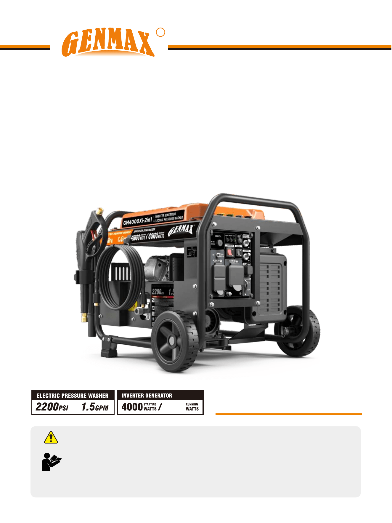
GM4000Xi-2in1
WARNING: SAVE THIS MANUAL FOR FUTURE REFERENCE
This manual contains important information regarding safety. Operation,
maintenance and storage of this product. Before use, read carefully and
understand all cautions, warnings, instructions and product labels. Failure
to do so could result in serious personal injury and/or property damage.
INVERTER GENERATOR
ELECTRIC PRESSURE WASHER
3200
1
UNPACKING
Always have assistance when lifting
the generator. The generator is heavy;
lifting it could cause bodily harm.
Avoid cutting on or near staples to
prevent personal injury.
Tools required - box cutter or similar device.
1. Carefully cut the packing tape on top of the carton.
2. Remove socket wrench, and oil funnel and save for
later.
3. Carefully cut two sides of the carton to remove the
generator.
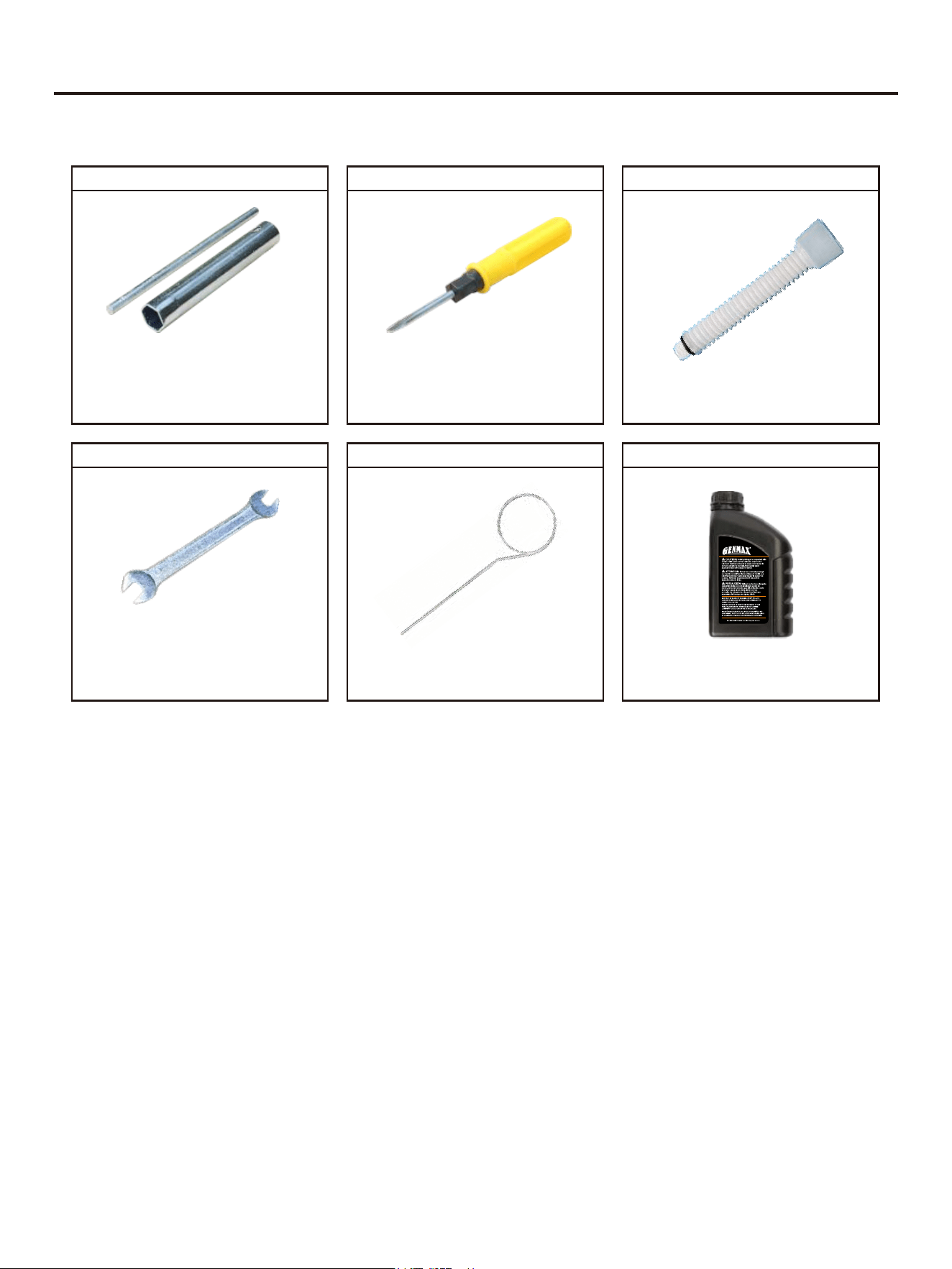
WHAT COMES IN THE BOX
Spark Plug Socket Wrench (1)
Dual-Purpose Screwdriver (1)
Warranty Information (1)
Funnel (1)
Wrench 8mm/10mm (1)
Nozzle Cleaning Needle (1)
Engine Oil (1)
DISCLAIMERS:
All information, illustrations and specifications in this manual are based on the latest information available at the
time of publishing. The illustrations used in this manual are intended as representative reference views only.
Moreover, because of our continuous product improvement policy, we may modify information, illustrations and/or
specifications to explain and/or exemplify a product, service or maintenance improvement. We reserve the right to
make any change at any time without notice. Some images may vary depending upon which model is shown.
ALL RIGHTS RESERVED:
No part of this publication may be reproduced or used in any form by any means - graphic, electronic or
mechanical, including photocopying, recording, taping or information storage and retrieval systems - without the
written permission of CHONGQING DINKING POWER MACHINERY CO., LTD
This manual contains important instructions for operating this inverter generator. For your
safety and the safety of others, be sure to read this manual thoroughly before operating the
generator. Failure to properly follow all instructions and precautions can cause you and others
to be seriously hurt or killed.
2
Description of Fittings
Spark Plug Socket Wrench
Used in spark plug maintenance,
inspection, and installation.
Phillips and slot blade
screwdriver used for generator
maintenance.
Dual-Purpose ScrewdriverFunnel
It's used to oil the generator.
Note: Actual tools may differ in appearance or design from image shown.
Wrench 8mm/10mm
Assorted wrenches used in
generator maintenance and
assembly. Commonly 8mm,
10mm.
Nozzle Cleaning Needle
Used to clean the nozzle outlet
hole.
Engine Oil
Be sure to add oil before starting
the generator.
3
LIMITED WARRANTY
1. DURATION : One (1) year from the date of purchase by the original purchaser ( retail customer ) on products used
solely for consumer applications; if a product is used for business, commercial, or industrial applications, the warranty
period will be limited to ninety (90) days from the date of purchase.
2. WHO GIVES THIS WARRANTY (WARRANTOR):
CHONGQING DINKING POWER MACHINERY CO., LTD
3. WHO RECEIVES THIS WARRANTY(PURCHASER):The original purchaser (other than for purposes of resale) of
the Genmax's inverter.
4. WHAT PRODUCTS ARE COVERED BY THIS WARRANTY: Any portable generator supplied or manufactured by
Warrantor.
5. WHAT IS COVERED UNDER THIS WARRANTY: Substantial defects on material and workmanship which occur
within the duration of the warranty period.
6. WHAT IS NOT COVERED UNDER THIS WARRANTY:
A. Transportation changes for s ending the product to Warrantor or its authorized service representative for warranty
service, or for shipping repaired or replacement products back to the customer; these charges must be borne by the
customer.
B. Damages caused by abuse, accident, shipping, misuse, overloading, modification, and the effects of corrosion,
erosion and normal wear and tear.
C. Warranty is voided if the customer fails to install, maintain and operate the product in accordance with the
instructions and recommendations set forth in the owner's manual(s), or if the product is used as rental equipment.
D. Pre-delivery service, i.e. assembly, oil or lubricants, and adjustment.
E. Items or service that are normally required to maintain the product, i.e. lubricants and filters.
F. Warrantor will not pay for repairs or adjustments to the product, or for any costs or labour, performed without
Warrantor's prior authorization.
EXCLUSIONS AND LIMITATIONS : Warrantor makes no other warranty of any kind, express or implied. Implied
warranties, including warranties of merchantability and of fitness for a particular purpose, are hereby disclaimed. This
warranty service described above is the exclusive remedy under this warranty; liability for incidental and consequential
damages is excluded to the extent permitted by law.
7. RESPONSIBILITIES OF PURCHASER UNDER THIS WARRANTY:
A. The purchaser must provide dated proof of purchase and must notify Warrantor within the warranty period.
B. Deliver or ship the serviced generator or component to the nearest Warrantor's authorized service representative.
Freight costs, if any, must be borne by the purchaser.
8. HAVE QUESTIONS?
Email: service@genmaxpower.com Phone: 866-960-2920
Model Number: _____________________________________
Name: ___________________________________________
Serial Number: ______________________________________
Street Address: ___________________________________
Date Purchased: ____________________________________
Purchased From: ____________________________________
City, State, ZIP: ____________________________________
Country: __________________________________________
Phone Number: ___________________________________
E-Mail: ___________________________________________
WARRANTY CARD
R

4
TABLE OF CONTENTS
LIMITED WARRANTY....................................................................................3
TABLE OF CONTENTS...........................................................................................................4
SAFETY ......................................................................................................................5
COMPONENTS ...........................................................................................................11
ASSEMBLE .....................................................................................................13
Installing the Feet .................................................................................................................13
Installing the Wheels ...........................................................................................................13
Installing the Handle ...........................................................................................................14
Installing the Spray Gun .....................................................................................................14
Secure the High Pressure Hose to the Frame .....................................................................14
Connecting the High Pressure Hose to the Spray Gun ........................................................14
Connect the High Pressure Hose to the Water Outlet .........................................................14
Connect garden hose to water intake ..................................................................................14
PREPARATIONS..........................................................................................15
Adding Gasoline ..............................................................................................................15
Adding Oil ..................................................................................................................15
Pre-use Inspection ............................................................................................................16
OPERATION ..................................................................................................................17
Starting the Generator ..........................................................................................................17
Using Cleaning ....................................................................................................................18
Selecting Nozzles ................................................................................................................18
Connecting Nozzle to Spray gun..........................................................................................19
Using the Spray Gun...........................................................................................................19
Washing/Cleaning.................................................................................................................19
Pressure Adjustment.......................................................................................................19
Using Chemicals.................................................................................................................20
Cleaning Tips....................................................................................................................20
Turn Off Water Supply.....................................................................................................20
Stopping the Generator........................................................................................................20
USING THE GENERATOR .............................................................................................22
Service Environment of the Generator ...............................................................................22
Generator Wiring ............................................................................................................22
Generator Grounding ...........................................................................................................23
MAINTENANCE ....................................................................................................................24
Spark Plug Inspection ........................................................................................................25
Adjustment of the Carburetor .............................................................................................26
Replacement of Oil ............................................................................................................26
Air Filter ............................................................................................................................27
Fuel Filter Screen ...............................................................................................................28
Cleaning Nozzle .........................................................................................................28
Cleaning Water Inlet Screen Filter ..................................................................................28
Cleaning the Generator .........................................................................................29
STORAGE AND TRANSPORT ................................................................................................30
Generator Storage ..............................................................................................................30
Storing Accessories ...........................................................................................................31
Winter Storage ...................................................................................................................31
Generator Transport ...........................................................................................................31
Preparation for Use After Storage .....................................................................................31
TROUBLESHOOTING ..................................................................................................32
TECHNICAL PARAMETERS ...........................................................................................35
CHOOSING A GENERATOR ....................................................................................................36
5
SAFETY
Personal and property safeties of you and others are very vital. Please read the Safety
Warning in the User's Manual and the decals of the generator set carefully.The Safety
Warning can alert you to those potential hazards that could harm you and others. In front
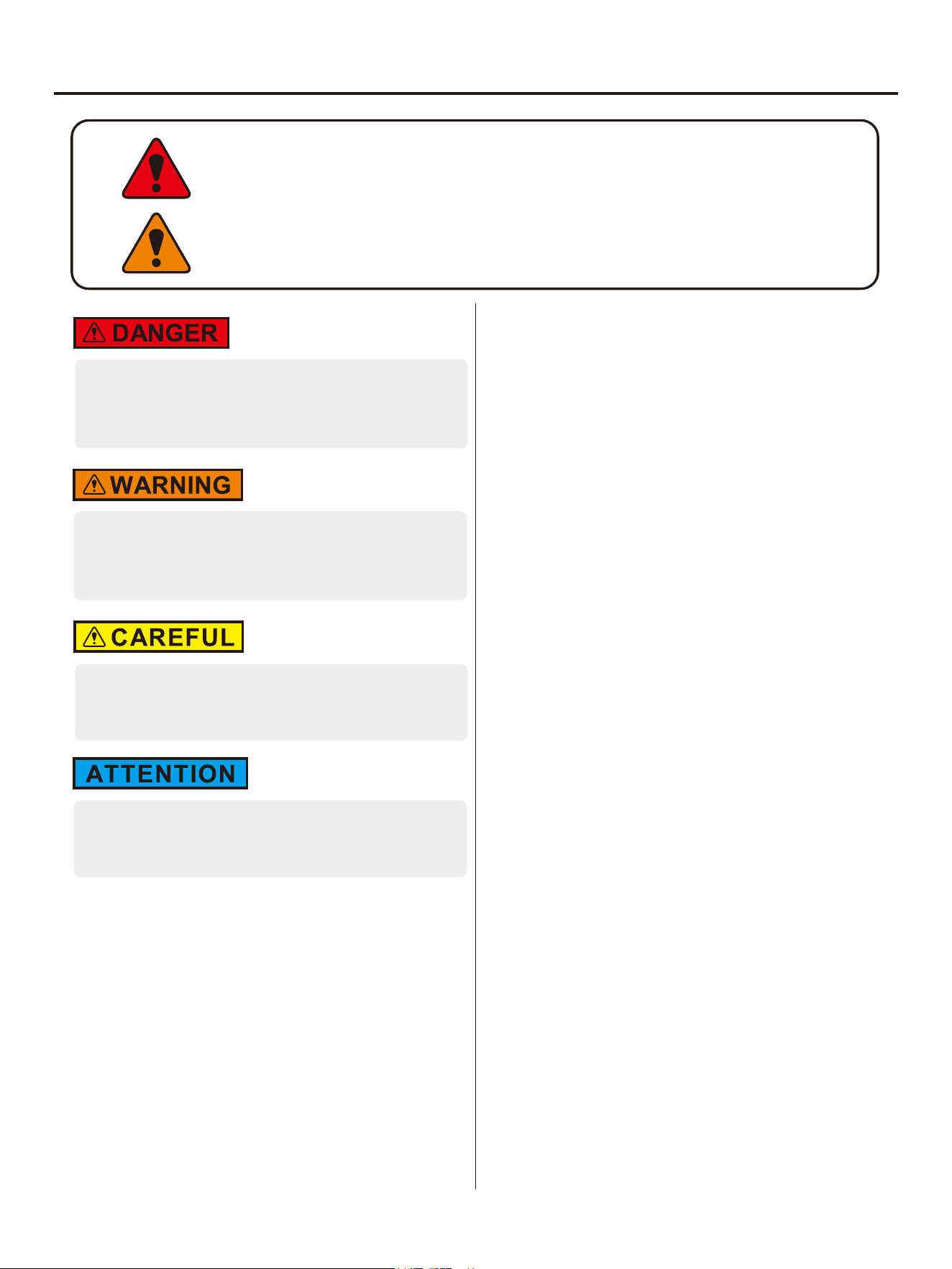
of each Safety Warning, there is one of four words "DANGER" "WARNING",
"ATTENTION", and "CAREFUL". Details are as follows:
Failure to follow the instruction will result in being
in peril of your life or extremely serious injury.
Failure to follow the instruction will result in being
in peril of your life or very serious injury.
Failure to follow the instruction will result in minor
injury.
Failure to follow the instruction will result in the
damage to your generator set and other properties.
For portable generators where the neutral is floating,
the operator's manual shall include the following
wording or equivalent:
The portable generator stator winding is isolated from
the frame and from the AC receptacle ground pin; and
Electrical devices that require a connection between
one conductor pin and the grounded receptacle pin
may not function properly.
NEUTRAL FLOATING
CO DETECT technology monitors the accumulation of
carbon monoxide (CO), a poisonous gas produced by
engine exhaust when the generator is running. If CO
Sensor detects unsafe elevated levels of CO gas, it
automatically shuts off the engine. CO Sensor is not a
substitute for an indoor carbon monoxide alarm or for
safe operation. DO NOT allow engine exhaust fumes
to enter a confined area through windows, doors, vents
or other openings. Generators must ALWAYS be used
outdoors, far away from occupied buildings with engine
exhaust pointed away from people and buildings.
Meets the requirements of ANSI/PGMA G300-2018.
CO TECHNICAL WARNING
CO Sentry Indicator Lights
Red
Carbon monoxide has accumulated around the
generator. After shut-off, the RED indicator light in
the CO Sentry area of the control panel will flash to
provide notification that the generator was shutoff due
to an accumulating CO hazard. The RED light will
flash for at least five minutes after a CO shut-off.
Move the generator to an open, outdoor area far away
from occupied spaces with exhaust pointed away.
Once relocated to a safe area, the generator can be
restarted. Introduce fresh air and ventilate the area
where the generator had shut down.
Yellow
A CO Sentry system fault occurred. When a system
fault occurs, the generator is automatically shut down
and the YELLOW indicator light in the CO auto-shutoff
area of the control panel will flash to provide
notification that a fault has occurred. The YELLOW
light will flash for at least five minutes after a fault.
The generator can be re-started, but may continue to
shutoff.
6
SAFETY
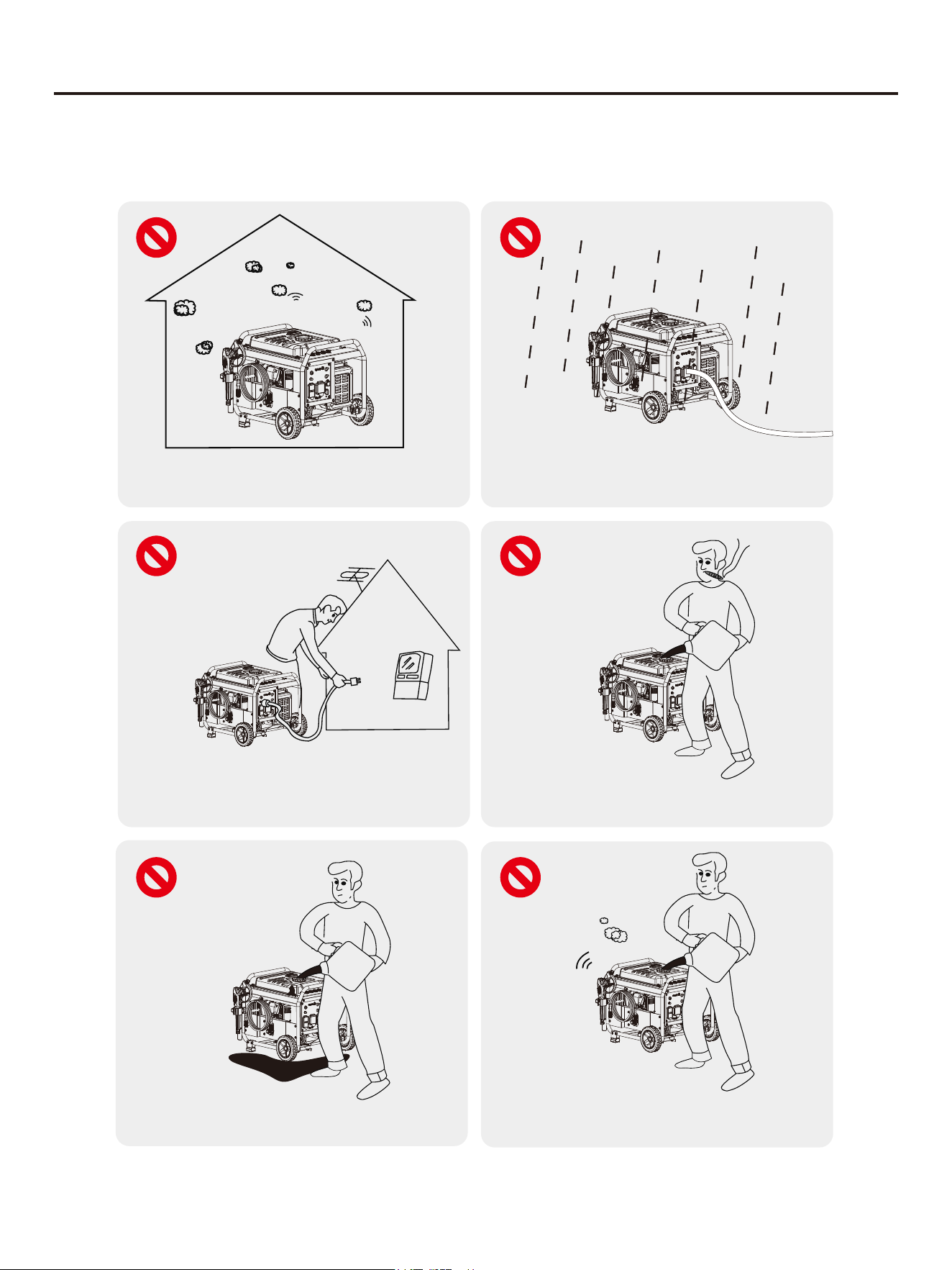
Before operating the generator, it will help you avoid accidents to read and understand the Manual and
familiarize yourself with the safe operation procedures of the generator.
Please do not use indoors
Please do not use in humid
environment
Do not directly connect to the
household power supply system
Please do not smoke when refueling
Please do not spill when refueling
Please shut down the generator
before refueling
7
SAFETY
• Keep guards in place and in working order. Never
operate this product with any guard or cover
removed. Make sure all guards are intact and
operating properly before each use.
• Remove adjusting tools and wrenches. If any
adjustments or maintenance has been performed,
make sure that all tools and adjusting wrenches are
removed from product before use.
• To reduce the risk of injury, keep all children and
visitors away from product when in use. All visitors
should wear safety glasses and be kept a safe
distance from work area.
• Keep the work area clear of all persons, particularly
small children, and pets.
• Use product for its intended use. Don' t force product
or attachment to do a job it was not designed for. Do
not use it for a purpose not intended. Use only
recommended accessories with this product. The
use of improper and or modified accessories may
cause risk of injury.
• Use proper clothing. Wear long pants and long
sleeves. Do not wear loose clothing, neckties, or
jewelry. They can get caught and draw you into
moving parts. Rubber gloves and nonskid footwear
are recommended when working outdoors. Do not
operate the equipment while barefoot or when
wearing sandals or similar lightweight footwear Also
wear protective hair covering to contain long hair.
• Always wear proper eye protection with side shields
marked to comply with ANSI Z87.1. Following this
rule will re-duce the risk of serious personal injury.
• Do not overreach or stand on a ladder, rooftop, or
other unstable support structure. Keep proper
footing and balance at all times.
• Never leave product running unattended. Turn power
off. Don' t leave product until it comes to a complete
stop.
• Keep the engine and pump free of grass, leaves, oil,
or grease to reduce the chance of a fire hazard.
• Keep the exhaust outlet free of foreign objects.
• Be completely knowledgeable with product controls.
Know how to stop the product and bleed pressure
quickly.
• Stay alert and exercise control. Watch what you are
doing at all times and use common sense. Do not
operate tool when you are tired. Do not rush.
• Do not operate the product while under the influence
of drugs, alcohol, or any medication.
• Check the work area before using product. Remove
all objects such as rocks, broken glass, nails, wire,
or string which can be thrown or become tangled in
the product.
• Do not direct high pressure spray stream at any
persons, animals and pets. Do not direct spray
stream.
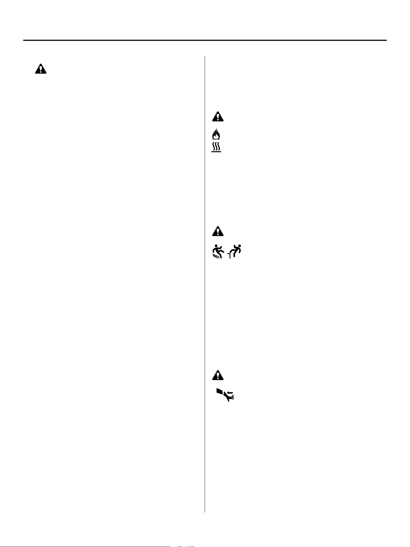
WARNING: READ AND UNDERSTAND ALL
SAFETY INSTRUCTIONS
Exhaust could ignite combustibles, resulting in
death or serious injury. Contact with muffler area
could cause burns resulting in serious injury.
WARNING: Fire / Hot Surface Hazard
• Never lift or carry the product or attempt to make
adjustments while the engine is running or hot.
• Do not attempt to touch the spark plug or plug wire
while the engine is running.
• Use only cold water with this product.
• For outdoor use only.
• DO NOT touch hot parts and AVOID hot exhaust
gases.
• Allow equipment to cool before touching.
• Keep at least 5 feet (1.5 m) of clearance on all sides
of pressure washer including overhead.
• Replacement part must be the same and installed in
the same position as the original.
WARNING: Slip or Fall Hazard
WARNING: Kickback Hazard
Use of pressure washer could create
slippery surfaces causing you to fall
resulting in death or serious injury.
• Kickback from spray gun could cause you to fall
resulting in death or serious injury.
• Operate pressure washer from a stable surface.
• The cleaning area should have adequate slopes and
drainage to reduce the possibility of a fall due to
slippery surfaces.
• Be extremely careful if you must use the pressure
washer from a ladder, scaffolding, or any other
similar location.
• Firmly grasp spray gun with both hands when using
high pressure spray to avoid injury when spray gun
kicks back.
Starter cord kickback (rapid retraction) will
pull hand and arm toward engine faster than
you can let go, which could cause fractures,
bruises, or sprains resulting in serious injury.
• NEVER pull starter cord without first relieving spray
gun pressure.
• When starting engine, pull cord slowly until
resistance is felt and then pull rapidly to avoid
kickback.
• After each starting attempt, where engine fails to run,
always point spray gun in safe direction, disengage
trigger lock and squeeze spray gun trigger to release
high pressure.
8
SAFETY
• Firmly grasp spray gun with both hands when using
high pressure spray to avoid injury when spray gun
kicks back.
WARNING: Fire / Explosion Hazard
Fuel and its vapors are extremely flammable and
explosive which could cause burns, fire or
explosion resulting in death or serious injury.
Risk of fire and serious burns: Never remove fuel cap
when unit is running. Shut off engine and allow the unit
to cool at least five minutes. Remove cap slowly.
WHEN ADDING OR DRAINING FUEL
• Turn pressure washer engine OFF and let it cool at
least 2 minutes before removing fuel cap. Loosen
cap slowly to relieve any pressure remaining in tank.
• Fill or drain fuel tank outdoors.
• DO NOT overfill tank. Allow space for fuel
expansion.
• If fuel spills, wait until it evaporates before starting
engine.
• Keep fuel away from sparks, open flames, pilot
lights, heat, and other ignition sources.
• Check fuel lines, tank, cap and fittings frequently for
cracks or leaks. Replace if necessary.
• DO NOT light a cigarette or smoke.
WHEN STARTING EQUIPMENT
• Ensure spark plug, muffler, fuel cap, and air filter are
in place.
• DO NOT crank engine with spark plug removed.
WHEN OPERATING EQUIPMENT
• DO NOT operate this product inside any building,
carport, porch, mobile equipment, marine
applications, or enclosure.
• DO NOT tip engine or equipment at angle which
causes fuel to spill.
• DO NOT spray flammable liquids.
WHEN TRANSPORTING, MOVING OR REPAIRING
EQUIPMENT
• Transport/move/repair with fuel tank EMPTY or with
fuel shutoff valve OFF.
• DO NOT tip engine or equipment at angle which
causes fuel to spill.
• Disconnect spark plug wire.
WHEN STORING FUEL OR EQUIPMENT WITH FUEL
IN TANK
Store away from furnaces, stoves, water heaters,
clothes dryers, or other appliances that have pilot light
or other ignition source because they could ignite fuel
vapors.
WARNING: Fire and Electrical Shock
Unintentional sparking could cause fire or
electric shock, resulting in death or serious
injury.
WHEN ADJUSTING OR MAKING REPAIRS TO
YOUR PRESSURE WASHER
• Disconnect the spark plug wire from the spark plug
and place the wire where it cannot contact spark
plug.
WHEN TESTING FOR ENGINE SPARK
• Use approved spark plug tester.
• DO NOT check for spark with spark plug removed.
WARNING: Fluid Injection
The high-pressure water that this equipment
produces could cut through skin and its
underlying tissues, resulting in serious injury
and possible amputation.
• Spray gun traps high water pressure, even when
engine is stopped and water is disconnected, which
could result in serious injury.
• If cut by fluid, call physician immediately. DO NOT
treat as a simple cut.
• DO NOT allow CHILDREN to operate pressure
washer.
• NEVER repair high pressure hose. Replace it.
• NEVER repair leaking connections with sealant of
any kind. Replace o-ring or seal.
• NEVER connect high pressure hose to nozzle
extension.
• Keep high pressure hose connected to pump and
spray gun while system is pressurized.
• ALWAYS point spray gun in safe direction,
disengage trigger lock and squeeze spray gun
trigger to release high pressure, every time you
stop engine.
• NEVER aim spray gun at people, animals, or
plants.
• DO NOT secure spray gun in open position.
• DO NOT leave spray gun unattended while
machine is running.
• NEVER use a spray gun which does not have a
trigger lock or trigger guard in place and in working
order.
• Always be certain spray gun, nozzles and
accessories are correctly attached.
WARNING: Moving parts hazard
Starter and other rotating parts could entangle
hands, hair, clothing or accessories, resulting
in serious injury.
• NEVER operate pressure washer without protective
housing or covers.
• DO NOT wear loose clothing, jewelry or anything
that could be caught in the starter or other rotating
parts.
• Tie up long hair and remove jewelry.
9
SAFETY
WARNING: Projectile hazard
Risk of eye or bodily injury. Spray could splash
back or propel objects resulting in serious injury.
• Always wear safety goggles marked to comply with
ANSI Z87.1 when using or in vicinity of this
equipment.
• Always wear protective clothing such as a long-
sleeved shirt, long pants and close-toed shoes.
• NEVER operate pressure washer when barefoot or
wearing sandals.
CAUTION: Engine Speed
Excessively high operating speeds could result in
minor injury. Excessively low speeds impose a heavy
load on engine.
• DO NOT tamper with governor spring, links or other
parts to increase engine speed. Pressure washer
supplies correct rated pressure and flow when
running at governed speed.
• DO NOT modify pressure washer in any way.
WARNING: Electrical Shock
Contact with power source could cause electric
shock or burn resulting in death or serious
injury.
• Never spray at or near an electric power source.
WARNING: Chemical Burn
Chemicals could cause burns resulting in death
or serious injury.
• DO NOT use caustic liquid with pressure washer.
• Use ONLY pressure washer safe detergents/ soaps.
Follow all manufacturer’ s instructions.
NOTICE: High pressure spray could damage fragile
items including glass.
• DO NOT point spray gun at glass when using red
(0°) nozzle.
• NEVER aim spray gun at plants.
NOTICE: Improper treatment of pressure washer
could damage it and shorten its life.
• NEVER operate units with broken or missing parts,
or without protective housing or covers.
• DO NOT by-pass any safety device on this machine.
• DO NOT tamper with governed speed.
• DO NOT operate pressure washer above rated
pressure.
• DO NOT modify pressure washer in any way.
• Before starting pressure washer in cold weather,
check all parts of the equipment to be sure ice has
not formed there.
• NEVER move machine by pulling on hoses. Use
handle provided on unit.
10
SAFETY
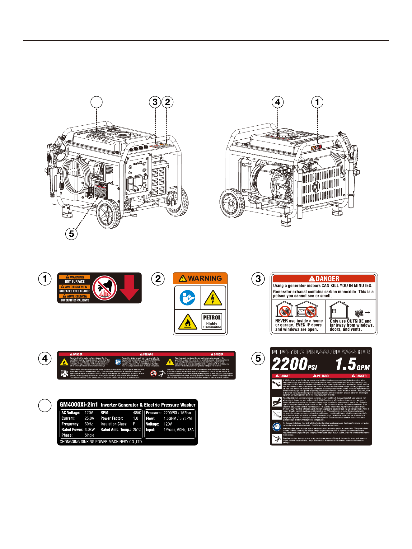
SAFETY LABELS AND DECALS
6
6
11
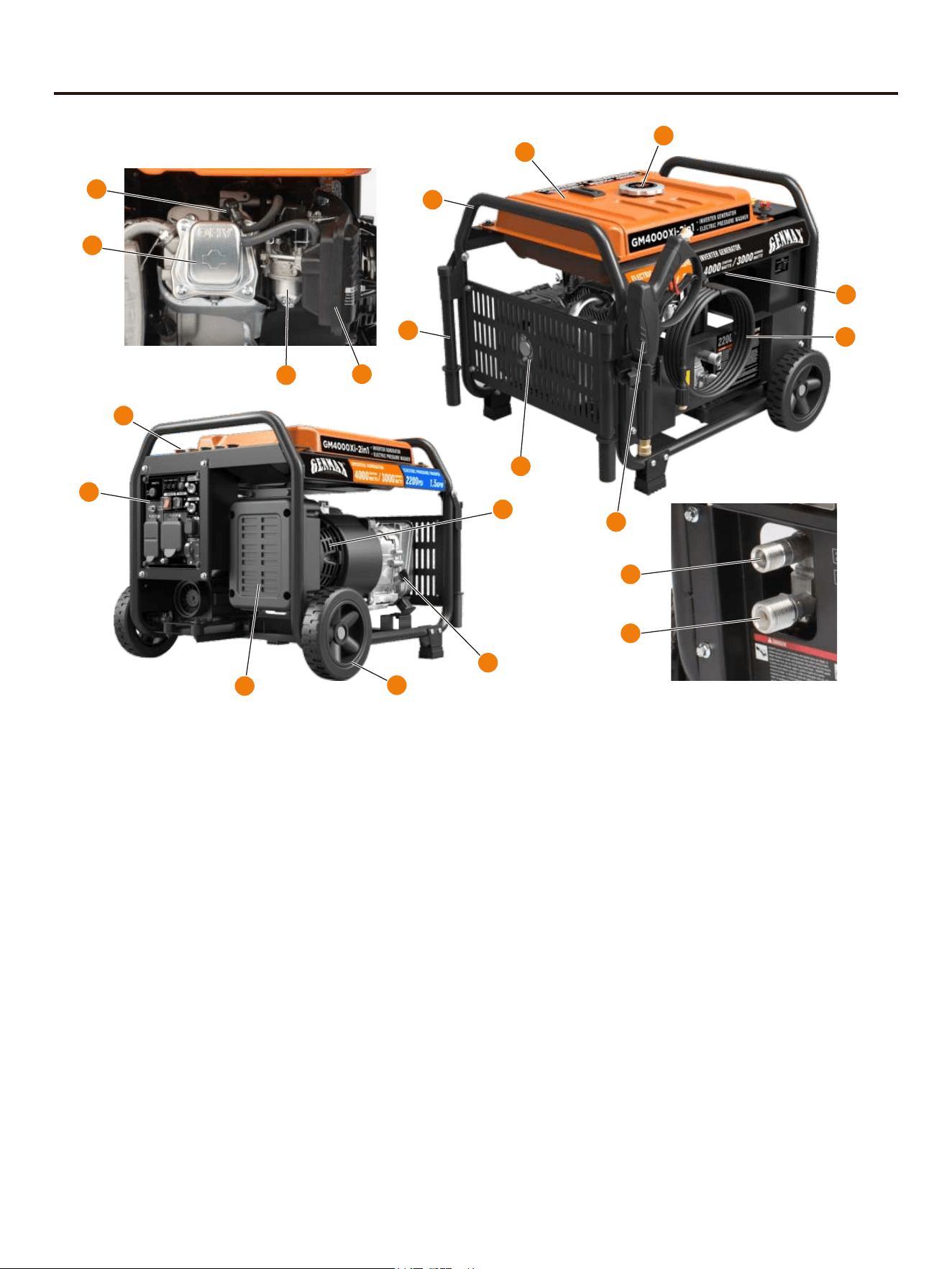
COMPONENTS
① Fuel Tank Cap: Open the fuel tank cap and fill with
proper amount of gasoline.
② Fuel Tank: Store the added gasoline.
③ Control Panel: Contains the reset breaker, outlets
and warning lights.
④ Magnetic Oil Dipstick: Absorb iron filings in the
engine oil. It is recommended to screw out the oil
dipstick every 50 hours to clean it.
⑤ Generator Frame: Protects the generator for easy
movement.
⑥
Wheel: Easy to move.
⑦ Muffler: Avoid contact until the engine is cooled
down. The spark arrestor prevents sparks from exiting
the muffler. It must be removed for servicing.
⑧ Spark Plug
⑨ Fuel Switch: Rotate to ON to turn on fuel, rotate to
OFF to turn off fuel.
⑩ Air Cleaner: To purify the waste gas.
⑪ Starter: Pull to start the engine.
⑫ Carburetor
⑬ Inverter: Conversion of direct current to alternating
current using high frequency bridge circuit.
⑭ Cylinder Head
⑮ Handrail
⑯ Spray Gun: Use the spray gun and lance to control
and direct the stream of water.
⑰ High Pressure Hose: The high pressure hose
included with this unit is light weight, flexible, and
durable. When not in use, the hose can be stored on
the hose retainer.
⑱ Water Outlet: Connection for high pressure hose.
⑲ Water Inlet: Connection for garden hose.
⑳ Nozzles: Nozzles of varying sizes are included with
this unit and can be used for different cleaning
applications.
3
6
4
15
7
13
2
1
5
9
10
14
8
12
11
16
17
18
19
20
12
COMPONENTS
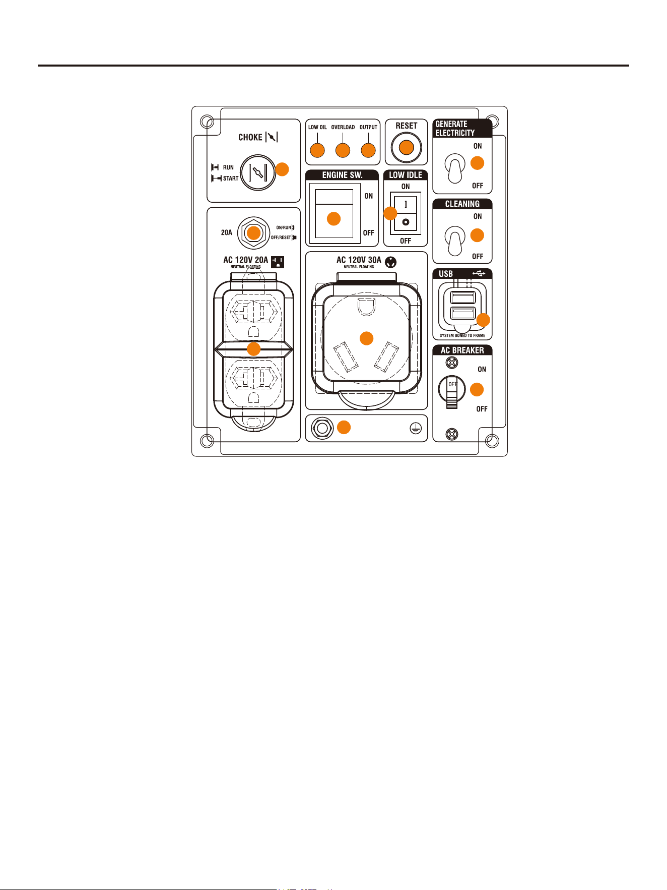
① 120-Volt, 20-Amp Outlet: The outlet is capable of
carrying a maximum of 20 amps.
② USB Duplex: 5V DC that come in 1 amps and2.1
amps.
③ Reset: If the generator is overloaded, the reset
breaker will trip. The engine will continue to run, but
there will be no output from the generator. Unplug the
devices and reduce the load. Push in the reset breaker
to reset it.
④ Low Idle: When turned to the ON position, the
engine will sense the load needed and run at a slower
RPM to save fuel.
⑤ Ground Terminal: The ground terminal is used to
externally ground the generator.
⑥ Low Oil Alarm: Indicates low oil level.
⑦
Overload Alarm: Indicates that the generator is
overloaded.
⑧ Output Indicator: Indicates the generator is ready
to be used.
⑨ 120/240-Volt, 30-Amp Outlet: The outlet is capable
of carrying a maximum of 30 amps.
⑩ 20A : The circuit breakers protect
Circuit Breaker
individual circuits from electrical overload.
⑪ Engine Switch: Press ON to start the engine,
press OFF to turn OFF the engine.
⑫AC Circuit Breaker AC circuit breakers control the :
output of all AC sockets to prevent overload or short
circuit of the generator.
⑬ Generate Electricity Switch: Turn the switch to
ON to turn on the power generation function, and to
OFF to turn off the power generation function.
⑭
Cleaning Switch: Turn the switch to ON to turn on
the cleaning function, and to OFF to turn off the
cleaning function.
CONTROL PANEL FEATURES GM4000Xi-2in1
8
678
3
13
14
11
4
10
1
9
2
12
5
13
ASSEMBLE
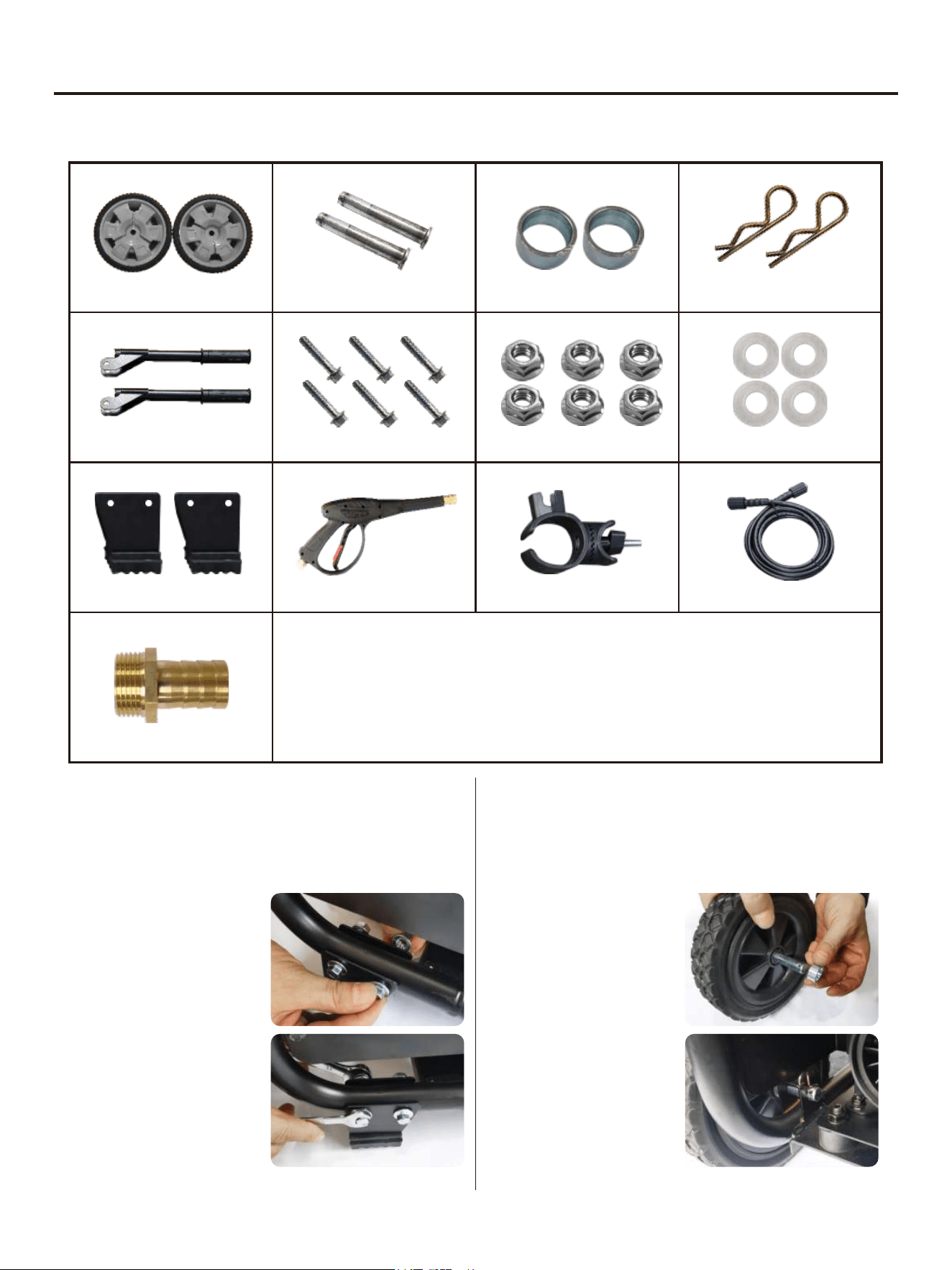
LIST OF PARTS
Wheel
Handle
Foot
Axle
R Pin
(Used of wheels)
Rubber Washer
(Used of wheels)
Bolt M8×45
(Used of Handle)
QTY: 2
QTY: 2
QTY: 2
QTY: 2
QTY: 2
QTY: 4QTY: 6
QTY: 6
Nut M8
(Used of Handle)
Washer
(Used of wheels)
QTY: 2
Spray Gun
QTY: 1
Spray Gun Holder
QTY: 1
High Pressure Hose 7m
QTY: 1
Water Inlet Connection
QTY: 1
INSTALLING THE FEET
1. Place the generator on a flat surface.
2. Place props beneath the generator to serve as
a temporary support.
3. Align the holes in a foot
with the holes in the
crossbar.
4. Insert bolts through the
holes in the foot and
holes in the cross bar.
5. Tighten bolts securely.
6. Repeat these steps to
install second foot.
INSTALLING THE WHEELS
1. Place the generator on a flat surface.
2. Place props beneath the generator to serve as
a temporary support.
3. Insert the axle between
the wheel and the
washer.
4. Install the wheel onto the
frame and insert the R
pin onto the axle.
5. Repeat these steps to
install second wheel.
14
ASSEMBLE
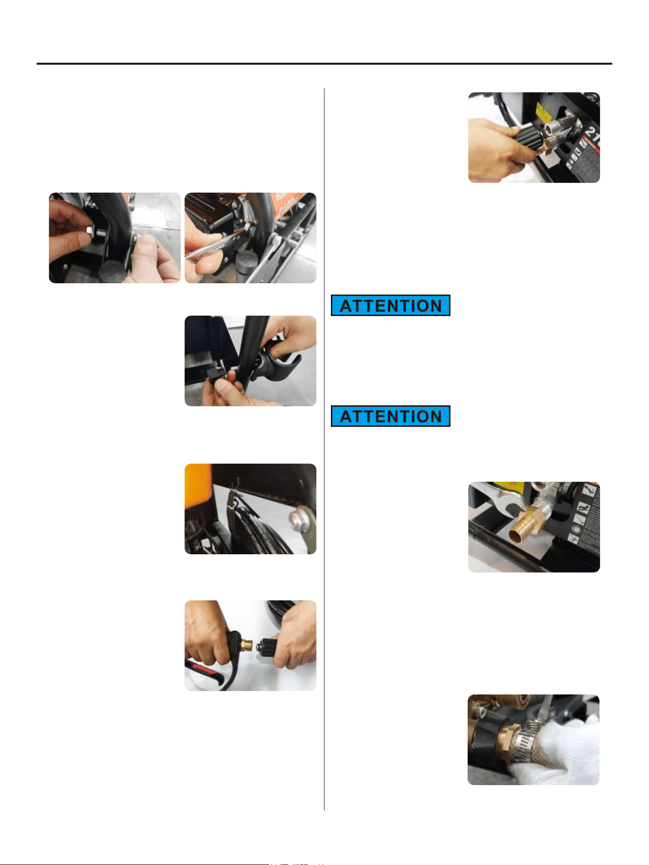
INSTALLING THE HANDLE
1. Two washers should be located on both sides of the
handlebar hole in the frame, and the handlebar should be
fixed on the frame with bolts.
2. Tighten bolts securely.
3. Repeat these steps to install second handle.
INSTALLING THE SPRAY GUN
1. Thread the threaded rod of
the spray gun base through
the hole on the frame.
(Direction of Muffler)
2. Adjust the direction and
tighten the nut.
3. Place the spray gun on the spray gun holder.
SECURE THE HIGH PRESSURE HOSE TO
THE FRAME
There is a hook behind the
frame above the cylinder head
used to hook the High
Pressure Hose onto the frame.
CONNECTING THE HIGH PRESSURE HOSE
TO THE SPRAY GUN
1. Pull the collar on the high
pressure hose back and
push the hose fitting firmly
onto the spray gun.
2. Screw the collar onto the
spray gun and tighten
securely.
NOTE: Be careful not to damage the threads on the spray
gun doing so could cause the gun to leak during use.
3. Gently pull on the hose to be certain it is secured.
CONNECT THE HIGH PRESSURE HOSE TO
THE WATER OUTLET
1. Uncoil and straighten the
high pressure hose to
remove any bends or kinks.
2. Pull the collar on the high
pressure hose back and
push the hose fitting firmly
into the threaded outlet on
the pressure washer.
3. Screw the collar onto the outlet and tighten securely.
NOTE: Be careful not to damage the threads on the spray
gun doing so could cause the gun to leak during use.
4. Gently pull on the hose to be certain it is secured.
CONNECT GARDEN HOSE TO WATER
INTAKE
Follow local regulations and ordinances when connecting
your pressure washer to a water supply. Some jurisdictions
may prohibit you from connecting directly to public drinking
water in order to prevent the possibility of chemicals feeding
back into the system. Connections made through a backflow
preventer or receiver tank are generally permitted.
The water used in this device must come from a water main.
DO NOT use this device with water from a lake, pool, pond,
etc. NEVER use hot water with this product.
1. Tighten the water inlet
connector to the water inlet.
2. Turn the water faucet completely off.
3. Uncoil and straighten the garden hose to remove any
bends or kinks.
4. Flush water through the hose for several seconds to
remove debris and then turn the faucet off again.
5. Inspect the screen inside the water inlet for damage or
clogs. Clean or replace as needed. NEVER connect a
garden hose without the screen in place.
6. Insert the garden hose into
the water inlet.
7. Thread the collar on the
inlet onto the garden hose.
Tighten securely.
15
PREPARATIONS
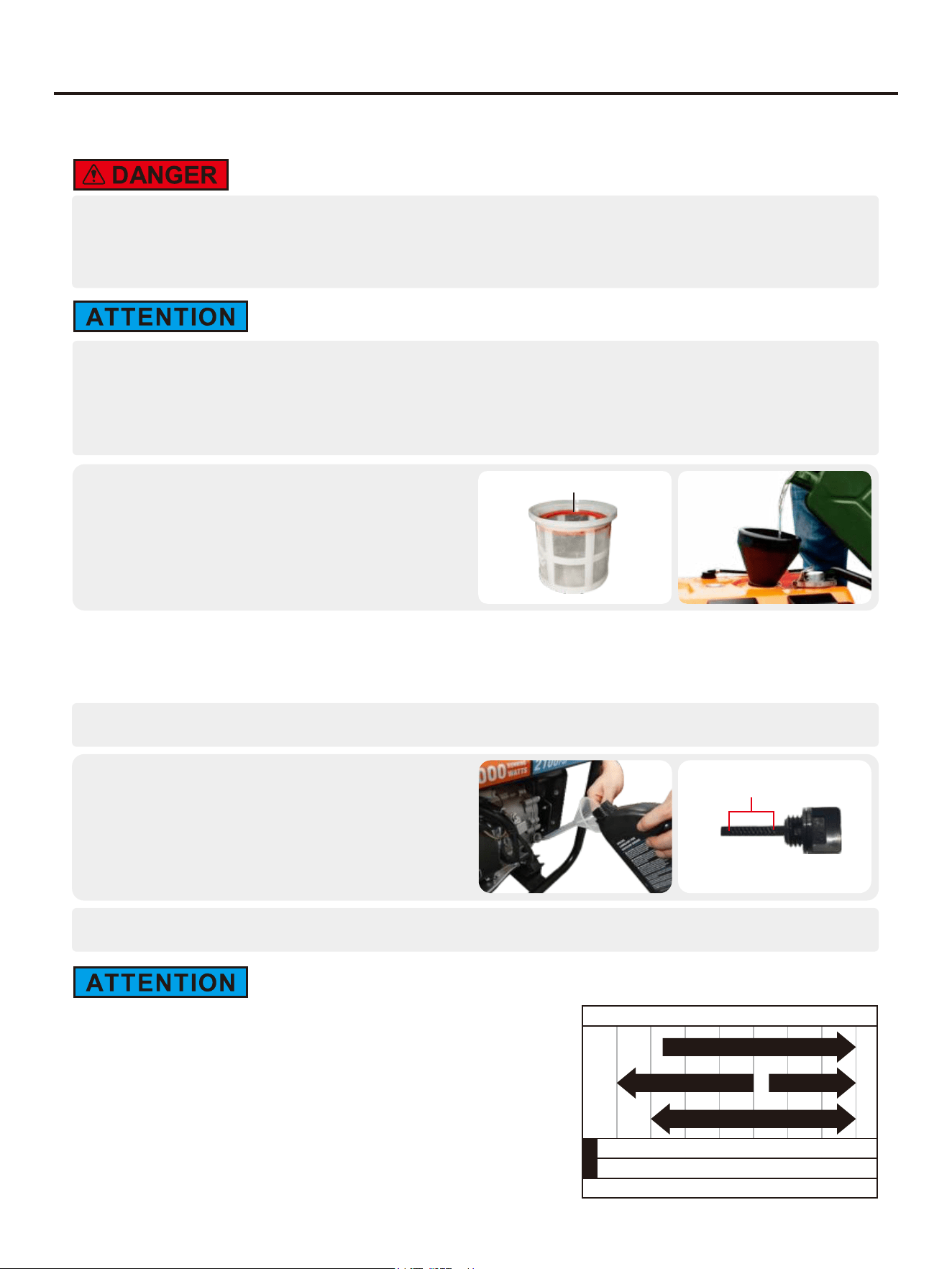
ADDING GASOLINE
• Fuel is flammable and toxic, please read the Safety Instruction carefully before refueling;
• Do not fuel too full, otherwise fuel will spill after fuel tank is warmed;
• After refueling, confirm that the fuel tank cap has been tightened.
• After refueling, dry gasoline residue with a clean and soft cloth in time to avoid damaging plastic
enclosure;
• Unleaded gasoline must be used, as leaded gasoline can seriously damage internal parts of the
generator;
Remove the tank cap and add gasoline.
Fuel tank capacity: 4.0gal (15L)
NOTE: The gasoline level should NOT be higher
than the red maximum fill ring on the fuel screen.
ADDING OIL
No oil is filled into this generator when being delivered. Do not start up the generator without filling sufficient oil.
Please place the generator onto a horizontal plane surface;
1.
Unscrew oil dipstick, Fill in 0.16gal(0.6L) oil
(SAE 10W/30 oil is recommended, of which
the grade is API standard Type SE or higher);
2.
Tighten the oil dipstick.
3.
Max Fill Line
Safe Operating Range
Oil Dipstick
Your generator was functionally tested in the factory and may contain
minimum residual oil. Additional oil is required to operate the unit. Do
not overfill.
Recommended Engine Oil Type
-20020406080100120
-28.9-17.8-6.74.415.626.737.848.9
℃
℉
Ambient Temperature
10W-30
10W-405W-30
5W-30 Full Synthetic
The recommended oil type for typical use is 10W-30 automotive oil.
However, using the listed conventional oils shown in the
"Recommended Engine Oil Type" chart may be used for typical use
including the first 5 hours of the break-in run time period of the engine.
If running generator in extreme temperatures, refer to the
"Recommended Engine Oil Type" chart.
16
PREPARATIONS
PRE-USE INSPECTION
Even if the generator is not in service, its important component may suddenly fails. Before the
generator is started up, if any of following components is unable to work properly, please inspect
and repair carefully.
Tip: The condition of the generator shall be inspected before using every time.
Pre-operation inspection
ProjectPossible CausesProbable Solutions
FuelCheck fuel level in fuel tank of the generator.Add fuel if necessary.
Oil
Check oil level of the generator.Add oil if necessary.
Check whether there is oil leaking.
Abnormal
conditions
during
operation
Check operating condition of the generator.
If there is any need, please do not hesitate to
consult your dealer.
17
OPERATION
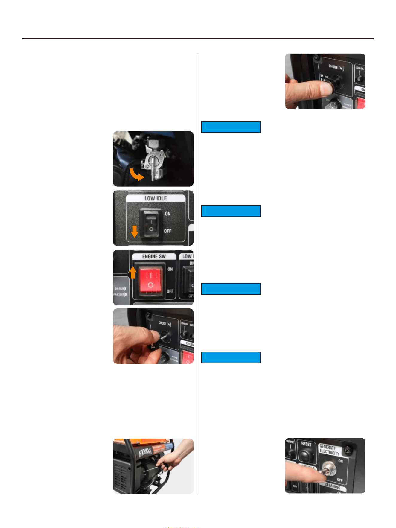
STARTING THE GENERATOR
1. Make sure the generator is on a solid, flat, level
surface.
2. Disconnect all electrical loads from the generator.
Place the generate electricity switch and cleaning
switch in the OFF position, and do not start or stop
the generator when the electrical equipment is
connected.
3. Turn the fuel switch to
“ON”.
4. Press the low idle
switch to “OFF”.
5. Press Engine Switch to
"ON".
6. Move the choke to the
START position.
NOTE: If the engine is
warm, move the choke
towards the RUN position.
7. Firmly grasp and pull the recoil handle slowly until
you feel increased resistance. At this point, pull the
recoil handle rapidly away from the generator until
the engine starts.
NOTE: Gently return the recoil handle into place after
starting the unit. Do not let it snap back against the
unit. During initial starting, additional pulls may be
required to prime the engine.
8. After the engine starts,
move the choke to the
RUN position.
USING GENERATE ELECTRICITY
1. Generate electricity
switch to "ON" position.
ATTENTION
For gasoline restarts with hot engine in hot ambient
temperature >86°F (30°C): Rotate the Choke Lever to
the “START” position for only one pull of the recoil cord.
If generator does not start after first pull, rotate the
Choke Lever to the “RUN” position for the next three
pulls. Too much choke leads to spark plug fouling and
engine flooding. This will cause the engine not to start.
ATTENTION
For gasoline starting in standard ambient
temperature >59°F(15°C): Keep Choke Lever in
“START” position for three pulls of the recoil cord. If
generator does not start after three pulls, rotate the
Choke Lever to the “RUN” position for the next three
pulls. Too much choke leads to spark plug fouling and
engine flooding. This will cause the engine not to start.
For gasoline starting in cold ambient temperature
< 59°F (15°C): Keep the Choke Lever in the “START”
position until engine starts. As soon as the engine
starts and runs smoothly turn the Choke Lever to the
“RUN” position. In extreme cold temperatures, this
may take several seconds.
If the engine starts but does not continue to run make
certain that the generator is on a flat, level surface. The
engine is equipped with a low oil sensor that will
prevent the engine from running when the oil level falls
below a critical threshold.
ATTENTION
ATTENTION
18
OPERATION
2. To add loads after starting the generator.
● When the generator output stabilizes, you can safely
connect loads to the control panel receptacles.
NOTE: Verify that all devices are turned off before
connecting them to the generator.
NOTE: Make sure that the wattage requirements for all
connected devices are in line with your generator's
capabilities.
● Connect and start the largest device or appliance.
● Allow the generator output to stabilize. Once stable,
the engine should run smoothly, and the device
should function properly.
● Connect and start the next largest device or
appliance.
● Allow the generator output to stabilize.
● Repeat this process for each additional load.
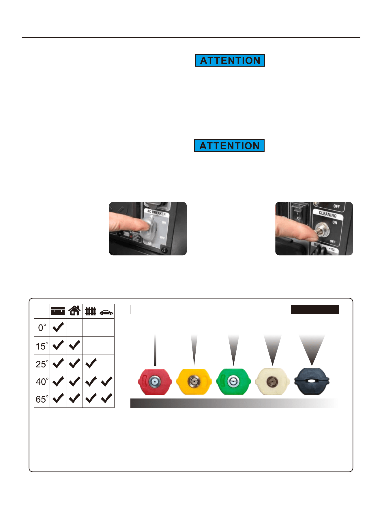
USING CLEANING
NOTE: The circuit
breaker switch must be
placed in the "ON"
position, otherwise the
generator will not output.
Cleaning switch to "ON"
position.
Before turning the cleaning switch to "ON", please
make sure to turn the water supply switch to "ON".
Running the pump in a dry water state can damage
internal components and render the pressure cleaning
machine inoperable.
The generate electricity function and cleaning function
can be used simultaneously. When using the cleaning
function, it will consume a rated power of 1800W, and
the generator can only output a rated power of 1200W.
Please note that the connected load should not exceed
the rated power of 1200W.
SELECTING NOZZLES
The quick connector on the spray gun can switch different nozzles according to different work scenarios.
HI PRESSURE, NO SOAP INJECTIONSOAP
0° RED65° BLACK15° YELLOW 25° GREEN 40° WHITE
AGGRESSIVEGENTLE
0° Nozzle-Red: This nozzle delivers a pinpoint stream of pressurized water and is extremely powerful. Use it for the
toughest cleaning jobs, although It covers only a small area. This nozzle should only be directed at surfaces that can
withstand intense high pressure such as metal or concrete. Do not use this nozzle to clean wood or soft surfaces.
15° Nozzle-Yellow: This nozzle delivers a 15-degree spray pattern for heavy duty cleaning and stripping. It should only
be used on surfaces that can withstand pressure from this nozzle.
25° Nozzle-Green: This nozzle delivers a 25-degree spray pattern for general tasks. It should only be used on surfaces
that can withstand pressure from this nozzle.
19
OPERATION
40° Nozzle-White: This nozzle delivers a 40-degree spray pattern for easily damaged surfaces. It should
only be used on surfaces that can withstand pressure from this nozzle.
65° Chemical Nozzle-Black: This nozzle is used to apply special chemicals and cleaning solutions. This
nozzle produces the weakest pressure stream of the nozzles.
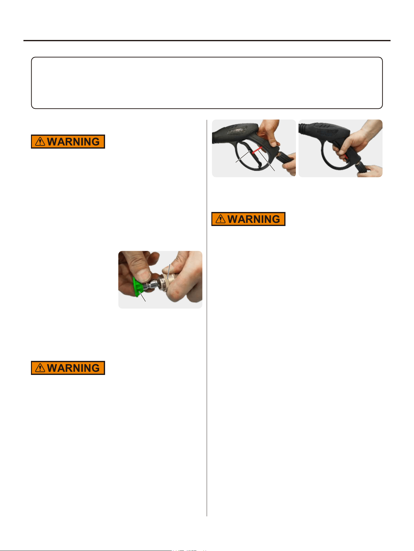
CONNECTING NOZZLE TO SPRAY GUN
Never place hands in front of nozzle, or point nozzle at
your face.
Never attempt to clean a clogged nozzle while attached
to the spray gun.
Never attempt to attach or remove spray gun or hose
fittings while Pressure Washer system is pressurized.
Turn off Pressure Washer. While pointing spray in a
save direction, release pressure by squeezing trigger.
Then lock the Gun Trigger before attempting to change
pressure nozzles.
1. To attach, pull quick
connect collar back,
insert nozzle into female
quick-disconnect spray
gun and press to lock in
place. Make sure collar
snaps into place.
Nozzle
Quick Connect
Collar
2. To detach, pull quick connect collar back and pull
nozzle to remove.
USING THE SPRAY GUN
Hold the spray gun and lance with two hands (one hand
to pull the trigger and the other to stabilize the gun) until
you get used to the “recoil”. Do not lose control of the
spray gun doing so could result in injury to yourself and
others.
● Start the pressure washer.
● Release the safety lock by pushing it down into the slot
in the trigger.
● Squeeze and hold the trigger to start the flow of water.
● Release the trigger to stop the flow of water.
● Lock the trigger by pushing it up to its original position.
Always engage the trigger lock before changing a
nozzle.
NOTE: Squeeze the trigger to make sure its locked and
will not move. ALWAYS keep the spray gun locked when
it’s not in use.
Trigger
Trigger Lock
WASHING/CLEANING
1. Firmly grip spray gun with both hands.
2. Start with a high degree fan nozzle, and gradually
use lower unit the nozzle meets the task.
3. Point the nozzle to a safe direction and squeeze the
spray gun trigger to allow the pump to purge air and
impurities in the system and then redirect the nozzle
to the working surface.
4. Clean vertical and sloped surfaces from the top
down.
5. When cleaning horizontal surfaces, occasionally use
the stream to clear the area of excess water.
6. For most effective cleaning, keep spray nozzle from
8 to 24 inches away from cleaning surface. If you get
spray nozzle too close, you may damage surface
being cleaned. It is not recommended to get closer
than 6 inches when cleaning tires.
PRESSURE ADJUSTMENT
Vary your distance: To change the effect of the
pressure on the surface being cleaned, vary the
distance between spray nozzle and the surface being
cleaned. The closer to the surface the higher the effect
of the pressure. As you pull away from the surface, the
pressure effect will reduce. For most effective cleaning,
keep the nozzle between 8 to 24 inches from surface
being cleaned.

20
OPERATION
USING CHEMICALS
NOTICE: Use only soaps and chemicals designed for
use with a Pressure Washer. DO NOT USE CHLORINE
BLEACH, ACIDS OR INDUSTRIAL SOLVENTS.
Chemicals, soaps and cleaning solvents will not siphon
when a high-pressure nozzle is used. Only use the
Black (low pressure) Nozzle when spraying detergents.
Fill Detergent Tank (if so equipped) with prepared
detergent solution and close the cap.
1. If your Pressure Washer is equipped with an on
board soap tank:
2. Fill the soap tank with detergent and close the lid.
3. Change the nozzle in the to black nozzle.
spray gun
4. Start the engine, and spray with soap.
5. If the Pressure Washer is not equipped with a soap
tank:
6. Make sure the Siphon Tube with Strainer is
connected to the brass barb near the high-pressure
hose connection area of the pump.
7. Submerge the strainer end of the siphon tube in the
soap/detergent.
8. Change the nozzle to black nozzle.
9. Start engine and spray with soap.
CLEANING TIPS
NOTICE: Never use the pressure washer garden hose
inlet to siphon detergent or wax. Leaving chemicals
and cleaning solutions inside the pressure pump could
damage it. Damages created by leaving soaps,
chemicals and cleaning solutions inside the pump can
void the warranty.
Overload Indicator
NOTE: The OVERLOAD light may turn on for a few
seconds as a large device starts. This is normal for
loads approaching the capacity of this generator.
1. The total combined load through the outlets on the
generator must not exceed the running power of the
unit.
2. If the OVERLOAD light turns on and the generator
stops producing power, it has been overloaded.
3. Turn off and disconnect all electrical devices and
stop the engine. Compare device requirements to
generator rating and reduce the total wattage of
connected devices if necessary. Move anything that
may be limiting generator ventilation away.
4. Check if any circuit breakers have tripped and make
sure that ALL circuit breakers are reset before
starting the generator again.
5. Restart the engine and reconnect devices while
being careful to not overload the generator.
Low Oil Indicator
1. If the engine oil level is too low, the LOW OIL light
turns on and the engine will automatically shut off.
2. The engine cannot be restarted until the proper
amount of oil has been added. Add the appropriate
type of oil until the oil level is at the proper level. SAE
10w-30 oil is recommended for general use.
Do not run the engine with too little oil. Engine will shut
off if engine oil level is too low.
Low Idle
1. Turn on a low idle mode (green light) to limit noise
and fuel consumption with a light generator load.
2. Turn off the low idle mode to run the engine at full
speed under the following conditions:
● Starting the generator.
● If the load exceeds 50%, it is recommended to turn
off the low idle mode.
STOPPING THE GENERATOR
1. Turn off and unplug all connected electrical loads.
Never start or stop the generator with electrical
devices plugged in or turned on.
2. Turn off the generate electricity and cleaning switch
to the OFF position.
TURN OFF WATER SUPPLY
Squeeze the Trigger to release excess pressure.
If pressure washer detergent has been used, run clean
water through the system to eliminate detergent residue
using the following procedure:
1. Fill the Detergent Tank (not supplied) with clean
water.
2. Remove the nozzle and restart the cleaning function.
3. Point spray gun in safe direction and hold down to
flush water through system until clean.
21
OPERATION
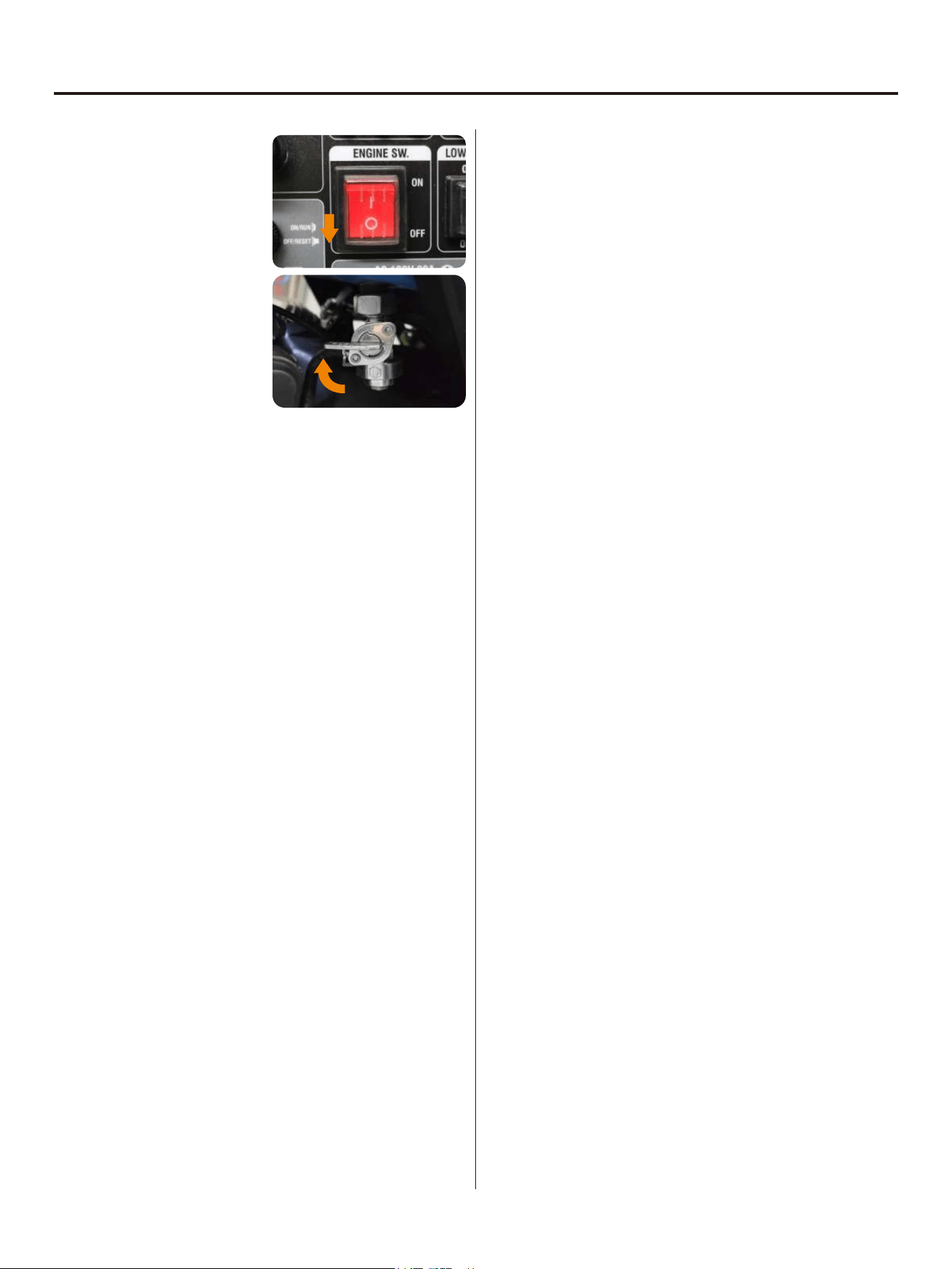
3. Turn the engine switch
to “OFF”.
4. Turn the fuel switch to
“OFF”.
5. Remove or consume all untreated gasoline if you
plan to store the generator longer than 3 months.
22
USING THE GENERATOR
SERVICE ENVIRONMENT OF THE GENERATOR
• Applicable temperature: 23℉(-5℃ )~ 104℉(40℃);
• Applicable humidity: below 95%;
• Applicable altitude: regions below 1,500 m (It shall be used by reducing power in regions above 1,000 m).
Standard atmospheric condition
• Ambient temperature Tr: 298k (77℉)(25°C)
• Relative air humidity Фr: 30%
• Absolute atmospheric pressure Pr: 100kPa
When actual environmental condition is inconsistent with the condition of output power of the generator
set:
• Every 5°C of increase in ambient temperature will reduce the power of generator by about 2%.
• Every 30% of increase in relative humidity of air will reduce the power of generator by about 1.5%.
• Every 300 m rising of ASL will reduce the power the generator by about 4.5%.
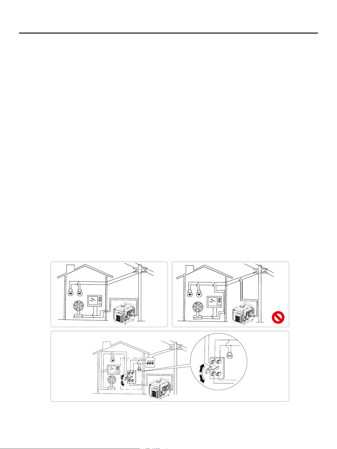
GENERATOR WIRING
• When the generator is connected to household power source as a backup power supply, the connection shall be
carried out by a professional electrician or a person familiar with electricity.
• After connecting the load to the generator, check carefully whether electrical connection is safe and reliable.
Improper electrical connection may cause generator damage, burning or fire.
• Avoid connecting this generator to commercial power outlet.
• When extending the cable, be sure not to exceed its length.
① 60m cross-section area is 1.5mm²
② 100m cross-section area is 2.5mm²
• The appearance of extension cable shall be protected by a layer of tough and elastic rubber cover (IEC25) or
other substitutes.
OK
OK
23
USING THE GENERATOR
Connection of AC power
All electrical equipment shall be disconnected before inserting the plug.
• Make sure that all electrical equipment, including wires and plugs, are in good condition before
connecting to the generator;
• Make sure that all loads driven by the generator are within rated load range;
• Make sure that load current is within rated current range of rated socket.
Tip: Make sure that the generator set is grounded, and if electrical equipment requires
grounding, the generator set must be grounded.
① Start up the engine;
② Turn energy-saving switch to "ON";
③ Insert the plug into AC outlet;
④ Make sure that AC indicator is lit up;
⑤ Switch on electrical equipment.
Tip: Before increasing engine speed, energy-
saving switch must be switched to "OFF". If the
generator set supplies power to multi loads or
electrical equipment, start from large to small
according to the size of each electrical
equipment.
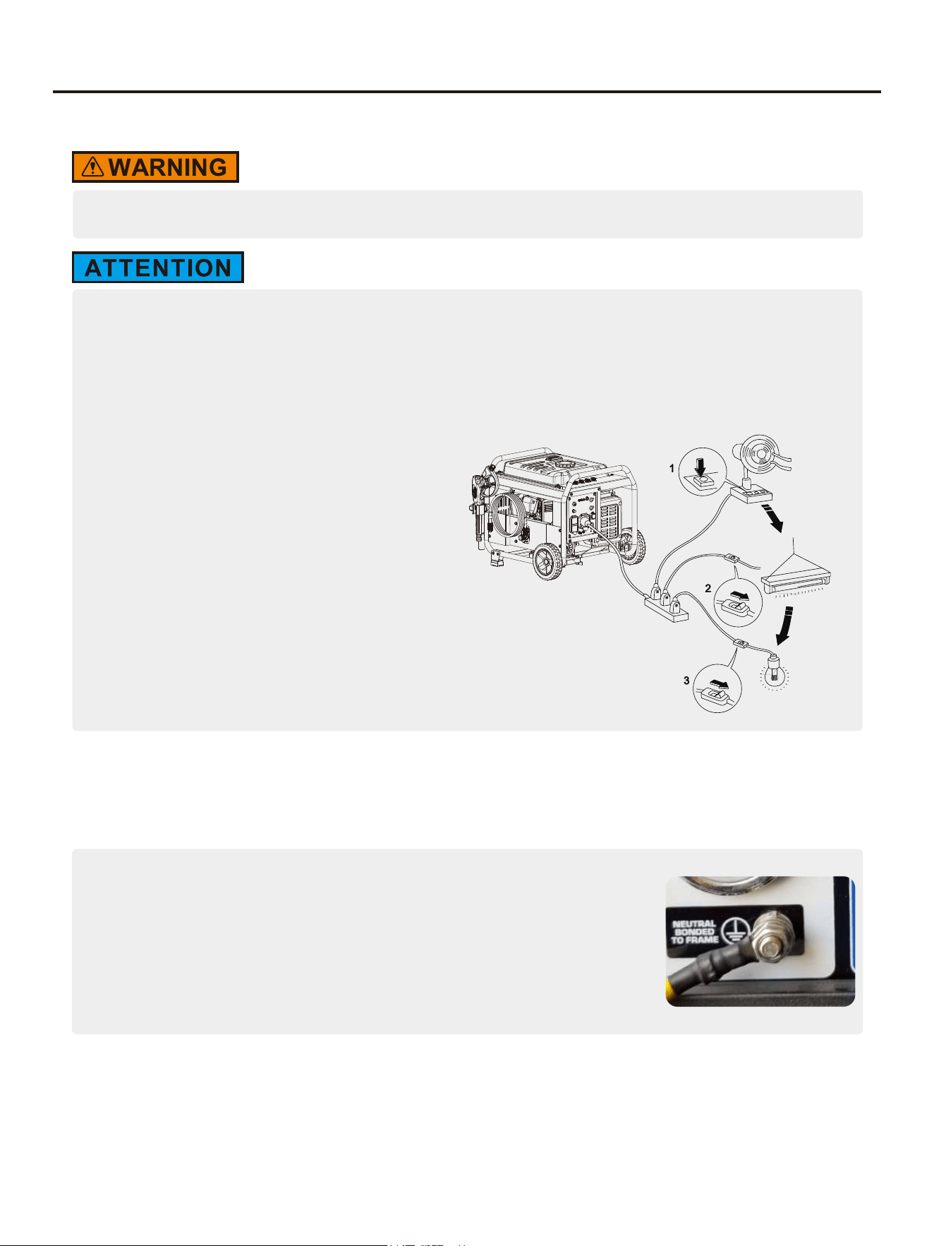
GENERATOR GROUNDING
① Please use grounding wire with sufficient electrical energy capacity;
② Connect one end of grounding wire reliable to grounding bolt on control panel
of the generator set;
③ Insert grounding body (iron rod with a diameter of 5 ~ 10mm) 200mm below
into the earth and lead it out with conductor;
④ Connect the other end of the grounding wire reliable to the led wire of
grounding body.
In order to prevent any damage to the generator caused by electric shock or improper electrical application, it is
recommended that the generator is grounded with good conductor with insulating sheath.
Tip: How to change the grounding method please refer to the website: https://www.genmaxpower.com/page/faq
24
MAINTENANCE
Good maintenance and service is the best guarantee for safe, economical and zero-failure operation. It also
contributes to environmental protection.
In order to keep the generator in good condition, you must inspect and maintain it regularly. The maintenance
schedule is as follows:
Maintenance cycle
Item
Each
First in 1 month
or 20 hours
Then every three
months or every
50 hours
100 hours per
year or use
Engine oil
Gearbox gear
Oil (if any)
Air cleaner
element
Settling cup (if any)
Spark plug
Spark eliminator
Idle speed
(if any)**
Valve clearance**
Fuel tank and
fuel filter***
Fuel line
Cylinder head,
piston
Displacement < 225cc, every 125 hours; displacement
capacity ≥ 225cc, every 250 hours.
Check-fill
Replace
Replace
Check oil
Inspection
Clean
Replace
Clean
Clean-adjust
Clean
Check-adjust
Check-adjust
Clean
Inspection
Remove
carbon
deposit**
Every two years (Please replace if necessary)
√
√√
√
√√
√
√
√
√
√*
√
√
√
√
* heseT items shall be replaced if necessary;
** heTse items shall be maintained by the dealer authorized by the Company, unless the
user has proper tools and maintenance ability.
• If it often works under high temperature or high load, oil shall be changed every 25 hours;
• If it often works in dusty or harsh environment, air cleaner element shall be cleaned every 10 hours. If
necessary, the air cleaner element shall be replaced every 25 hours;
• It shall be maintained on spot-inspection cycle and time, whichever is earlier;
• If maintenance cycle time has elapsed, perform the maintenance as soon as possible as per the table
above.
25
Please shut down the engine first before performing any maintenance. The engine shall be placed in a
horizontal position. In order to prevent the engine from starting up, separate spark plug cap shall be
separated from spark plug.
Do not use it indoors or use it in a tunnel, cave or other places ventilated poorly. Make sure that work area is
well ventilated. Exhaust gas from the engine contains toxic gases, carbon oxides, and the inhalation can
cause shock, loss of consciousness, and even death.
SPARK PLUG INSPECTION
Spark plug is an important part of the generator, which must be inspected regularly.
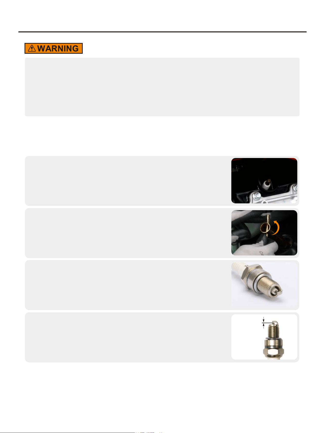
Remove the spark plug cap;
1.
Insert the screwdriver into the sleeve, to screw it counterclockwise, and then
remove the spark plug;
2.
Check whether there is discoloration, and remove carbon deposits.Check
whether there is little pale to moderate brown on ceramic cores around
center electrode of the spark plug;
3.
Tip: The spark plug clearance is required to be measured by line thickness gauge, which shall be adjusted if
necessary.
Check the model of spark plug and clearance.
Spark plug gap: 0.7-0.8mm
Standard spark: BP6ES
4.
0.7~0.8mm
MAINTENANCE
26
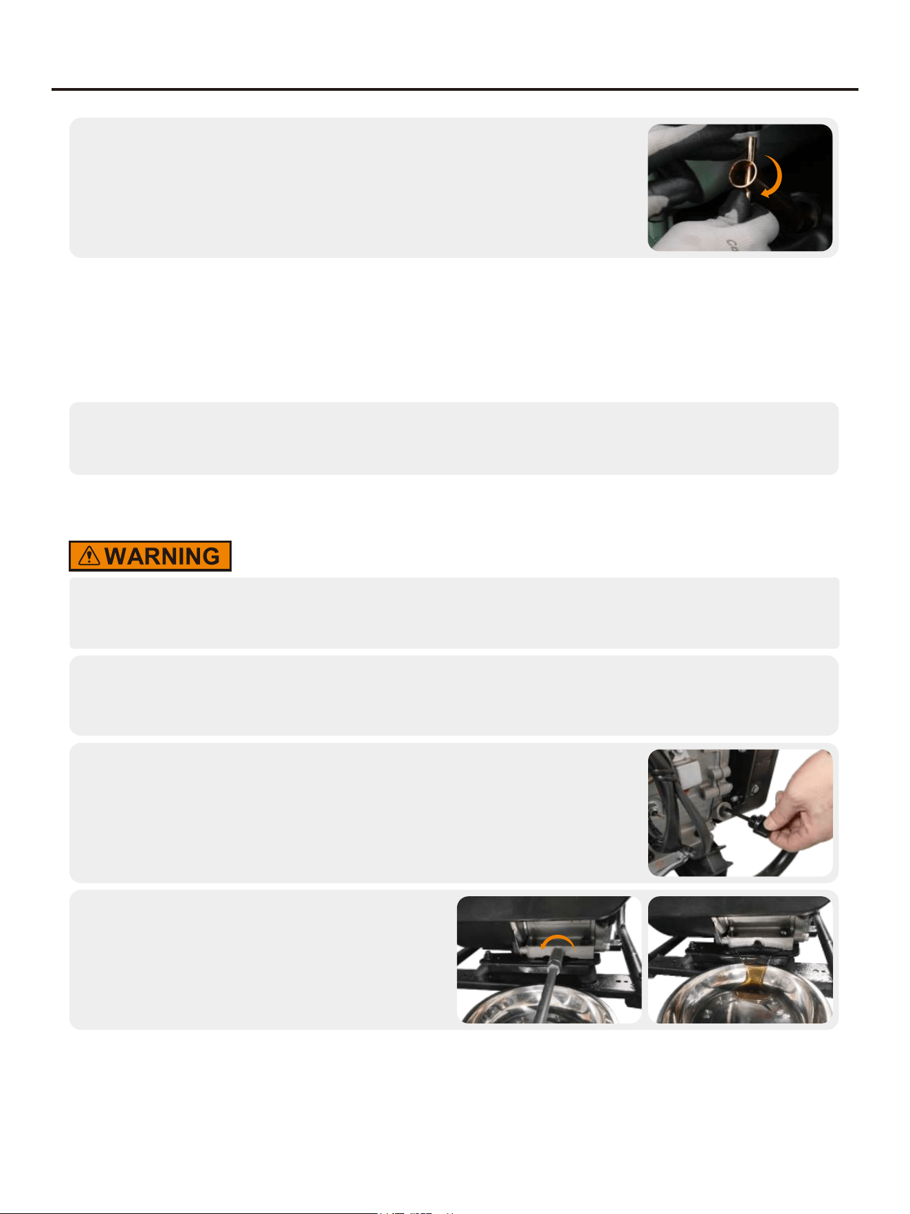
Install the spark plugs in reverse order of removal.
Spark plug torque: 22.5±2.5N.m(199±22in-lb)
5.
Tip: If there is no torque wrench when installing the spark plug, a better estimation method is to screw it 1/4-1/2
turns by force after screwing it in place, but the spark plug shall be screwed to specified torque as soon as
possible.
ADJUSTMENT OF THE CARBURETOR
The carburetor is an important components of the engine. The adjustment shall be carried out by a dealer with
professional knowledge, professional data and equipment, to ensure that the adjustment is proper.
REPLACEMENT OF OIL
Do not drain the oil immediately after turning off the generator. Oil temperature is very high, when
operating, take care to avoid scalding.
Put the generator on a horizontal surface, start the generator, run it for a few minutes to increase its
temperature, and then turn off the engine;
1.
Unscrew oil dipstick;
2.
Place an oil pan (or suitable container) under the
oil drain bolt, remove the oil drain bolt and allow
the oil to drain;
3.
MAINTENANCE
27
Refill oil to a proper level, tighten oil dipstick.
4.
Recommended oil: SAE S10W/30
Oil grade: API standard Model SJ or higher
Volume: 0.16gal(0.6L)
AIR FILTER
Dirty air cleaner may prevent air from flowing into the carburetor. In order to prevent failure of the carburetor,
please maintain air cleaner regularly. If being used in a dusty environment, it shall be maintained frequently.
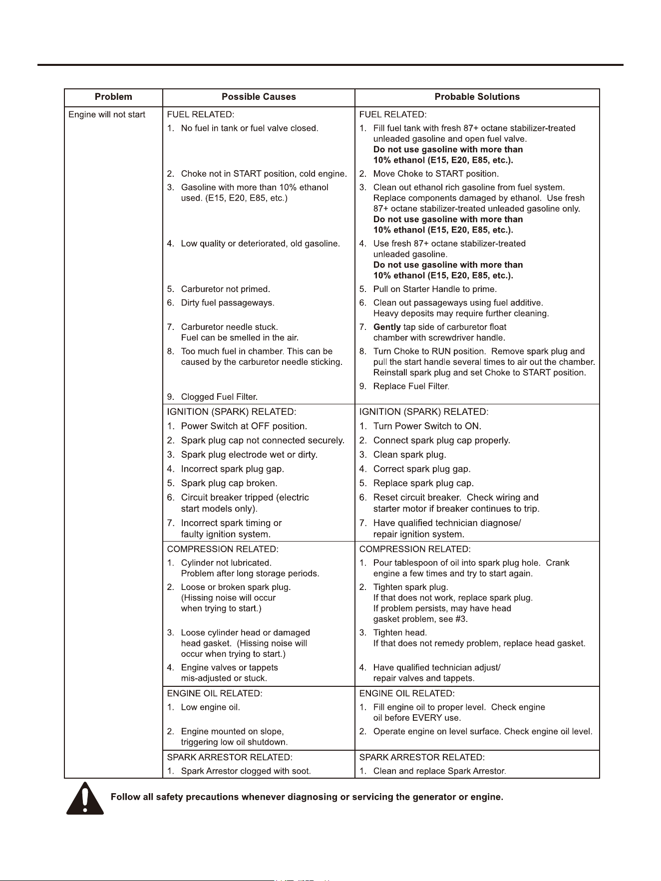
Remove screws, to remove cover plate of air
cleaner ;
1.
Clean foam cleaner element with cleaning solvent and blow it dry, Put a few
drops of oil on the filter element;
2.
Be sure not to twist the foam cleaner element forcibly to avoid damage.
Put foam cleaner element into air cleaner;
Tip: Make sure that the surface of foam cleaner element is in close contact
with air cleaner, and there shall be no gap leaking air. Be sure not to start the
engine before air cleaner is assembled, because it will generate excessive
toxic gas and wear the cylinder;
3.
Reassemble empty air cleaner cap back to original position, and tighten
screws.
4.
MAINTENANCE

28
FUEL FILTER SCREEN
Be sure not to open fuel tank of the generator in a place where smoking or with flame.
1. Remove fuel tank cap and fuel tank filter screen.
2. Clean fuel tank filter screen with gasoline.
3. Wipe filter screen dry, and put it back into fuel tank.
4. Reassemble fuel tank cap.
Be sure to screw fuel tank cap tight.
CLEANING NOZZLE
Occasionally, the spray gun can become clogged with foreign materials such as dirt. When this happens, excessive
pressure can develop. Whenever the pressure nozzle becomes particularly clogged, the pump pressure will pulsate.
It should be immediately cleaned.
Make sure pressure washer is off and spray gun is locked.
1.
Trigger
Trigger Lock
Remove high pressure spray nozzle from the spray gun. Using the nozzle
cleaning needle (provided), remove any obstructions by inserting and
carefully moving the pin back-and-forth through nozzle hole under clean
running water.
2.
After cleaning, remove the needle from nozzle and store for future use. Reassemble pressure nozzle to
spray gun.
3.
CLEANING WATER INLET SCREEN FILTER
The pump water inlet has a filter screen that should be checked periodically and cleaned if necessary.
MAINTENANCE

29
Disconnect inlet water hose.
1.
Remove filter by grasping end and pull straight out.
2.
Clean screen filter by flushing both sides with water.
3.
Insert screen filter back inside water inlet port.
4.
NOTICE: Do not operate Pressure Washer without water inlet screen filter in place.
CLEANING THE GENERATOR
Do not store or operate your generator in dirty, dusty, or corrosive environments. Do not allow foreign materials
and debris to clog the vents on the unit.
NEVER clean the generator with a garden hose. Water can damage the generator's fuel system and electrical
components. If the unit needs to be cleaned, use a soft brush and damp cloth to clean the exterior and use low
pressure air (no greater than 25 psi) to clean the vents. Never use gasoline as a cleaning agent.
MAINTENANCE

30
STORAGE AND TRANSPORT
GENERATOR STORAGE
If it is stored long-term, in order to prevent aging, you shall take some storage measures.
Turn the unit off and allow it to cool a minimum of 30 minutes before storage. Keep the unit upright. Do
not store the generator on its side. Drain fuel before storing the unit. Store the unit and the fuel
separately in well-ventilated areas away from sparks, open flames, pilot lights, heat, and other sources
of ignition.
1.
Gasoline stored for as little as 30 days can deteriorate, causing gum, varnish,
and corrosive buildup in fuel lines, fuel passages, and the engine. This
corrosive buildup restricts the flow of fuel, which can prevent the engine from
starting after a prolonged storage period.
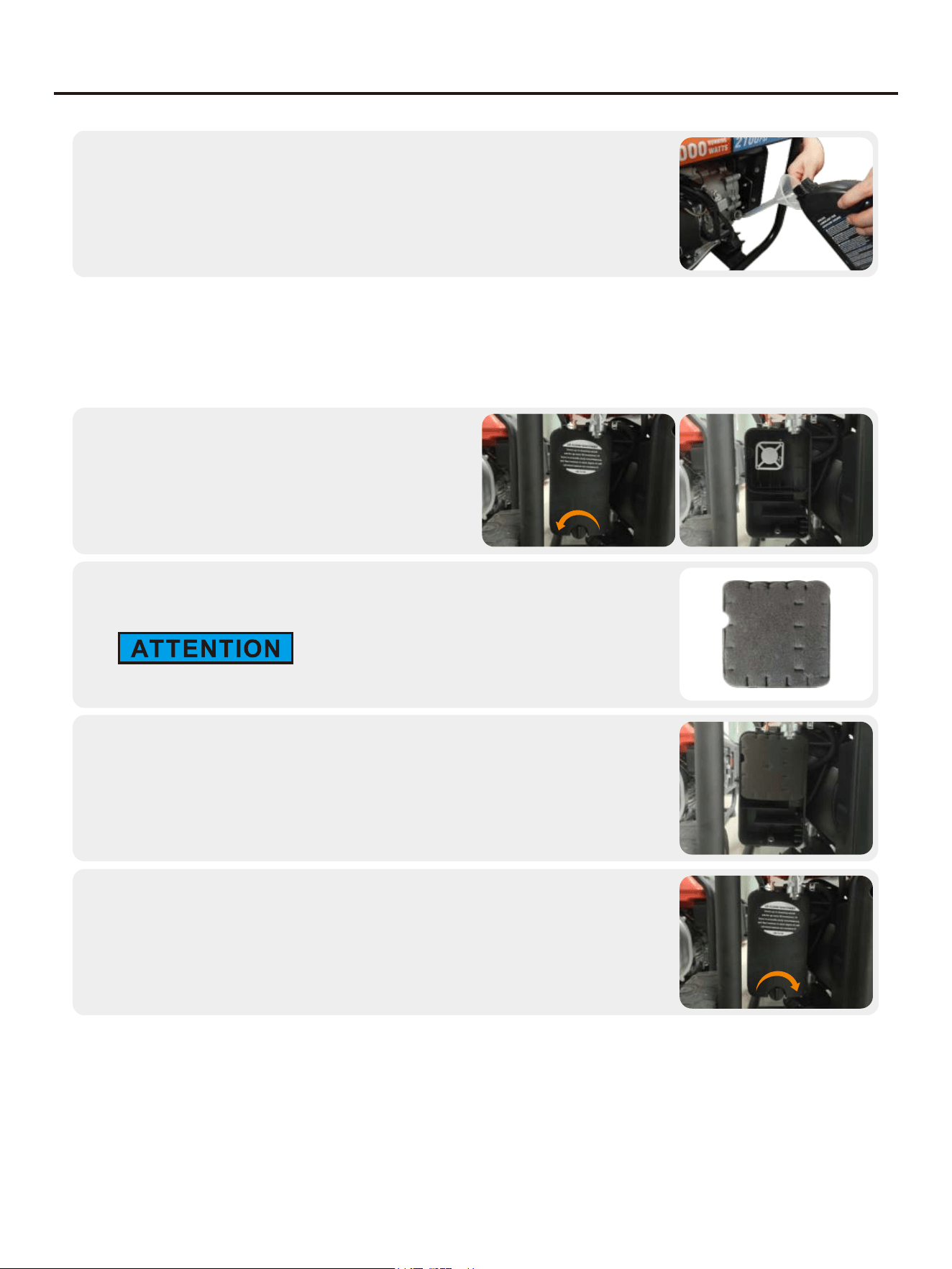
Open fuel tank cap, to take out fuel filter screen. Pump all fuel in fuel tank into
special fuel tank, and then reassemble fuel tank cap back.
2.
Start up the engine to burn off fuel in the carburetor, and then shut it down.
3.
Tip: Do not connect any electrical equipment. Running time of the engine depends on remaining fuel in the fuel
tank.
Locate the carburetor to drain the remaining gasoline and place a suitable
container to capture the emitted fuel.
4.
Loosen the carburetor drain screws until you see fuel draining from the
carburetor.
5.
Allow fuel to drain into the container and tighten the drain screws on the
carburetor.
6.
Unscrew oil dipstick, and drain oil in the crankcase off. Fill new oil to upper oil limit, and then assemble
oil dipstick.
7.
Remove the spark plug and pour 5-10ml of clean oil into the combustion chamber. Turn the crankshaft a
few times to distribute the oil, then reassemble the spark plug.
8.

31
STORAGE AND TRANSPORT
Gently pull startup handle until you feel resistance, allowing both inlet valve
and exhaust valve to be closed.
9.
Place the generator set in a clean and dry area.
10.
STORING ACCESSORIES
The pressure washer is equipped with places to store your accessories as shown.
Place spray gun into gun holder.
WINTER STORAGE
Make sure the pressure washer hose is free of all water before storing for winter. In order to prevent corrosion
and keep the water pump from freezing you will need to add RV (non-toxic) antifreeze or similar pump-protection
specifically made for pressure washers. Follow the manufacturer's instructions for use.
GENERATOR TRANSPORT
• When the generator set is transported, it shall be ensured that there is no fuel spilling;
• Do not fill excessive fuel into fuel tank;
• Do not run the generator, and avoid direct sunlight;
• Do not transport the generator set on rough road for long time.
PREPARATION FOR USE AFTER STORAGE
1. Slowly pull the starter cord a few times to clean oil from the cylinder or to eject any pump protector from the
pump which may have been added prior to storage.
2. Remove the spark plug from the cylinder. Wipe oil from the spark plug and return it to the cylinder and re-
tighten.
3. Reconnect the spark plug wire.
4. Refuel engine per earlier instructions in this manual.
32
TROUBLESHOOTING
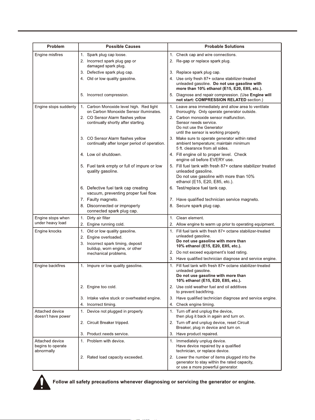
33
TROUBLESHOOTING

34
TROUBLESHOOTING
No pressure or low
pressure
1. No nozzle inserted into wand quick connect
fitting.
2. Inadequate water supply.
3. Hose fitting leaking.
4. Nozzle is clogged.
5. Air in hose.
6. Water inlet filter screen obstructed.
7. Choke lever in “START “ position.
1. See “Selecting The Right Nozzle”.
2. Water supply must be 5 GPM @ 20 PSI minimum.
3. Check and tighten all hose fittings.
4. Clean Nozzle (See “Cleaning Nozzle” on Page 20).
5. Squeeze trigger to remove air.
6. Remove and clean filter screen.
7. Move choke to “RUN” position.
Water or Oil Leaking at
Pump
1. Not enough water supply.
2. Water inlet screen is clogged.
3. Nozzle is clogged.
4. Nozzle has mineral build up.
1. Check water supply hose for kinks, leaks, or blockage. Open
faucet all the way.
2. Remove and clean filter screen.
3. Clean Nozzle (See “Cleaning Nozzle”).
4. Remove Nozzle and clean with vinegar.
Output pressure varies
1. Loose connections.
2. Worn or broken O-rings.
3. Pump head or tubes damaged from freezing.
1. Check and tighten all connections.
2/3. Please submit to an authorized dealer.
No intake of detergent1. Detergent hose not properly inserted into unit.
2. Soap injector hose cracked or split.
3. Wrong Nozzle.
4. Injector turned off.
5. Injection hose strainer clogged.
6. Nozzle blocked.
7. Dried detergent in injector.
1. Replace hose.
2. Push firmly onto injector fitting.
3. Switch to black SOAP nozzle.
4. Turn on injector.
5. Clean hose and strainer.
6. Clean nozzle.
7. Dissolve by running warm water through the injection hose.
Run clean water through injector until clear.
Water leaking at spray
gun connection
1. Check and tighten all connections.
2. please submit to an authorized dealer.
1. Loose hose connection.
2. Worn, broken or missing O-ring.

35
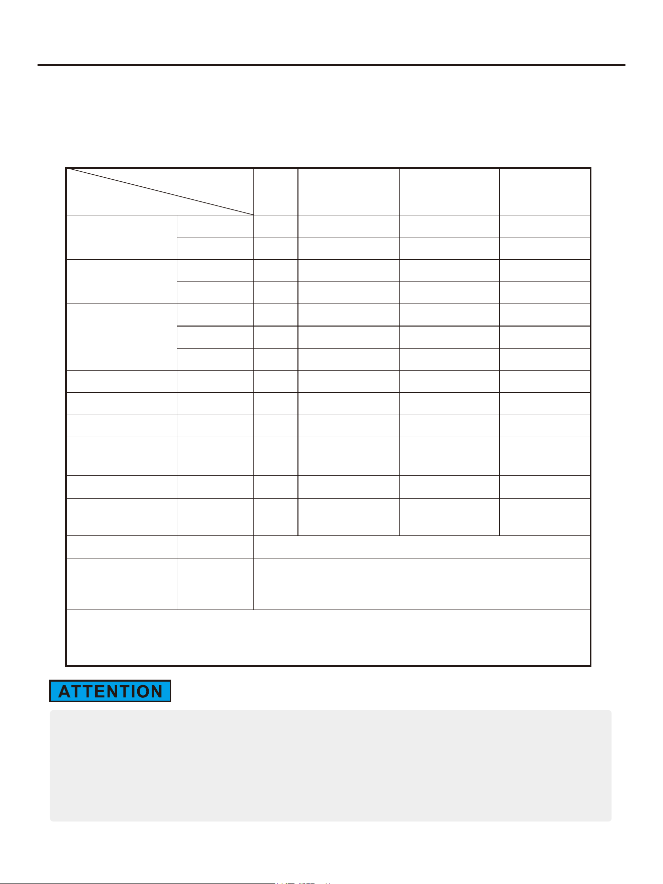
TECHNICAL PARAMETERS
Item
GM4000Xi-2in1
Engine Model
Engine Type
Displacement (cc)
Gas Distribution Mode
Cooling Mode
Rated Speed (RPM)
Starting Method
Fuel Tank Volume (gal)
Fuel Type and Grade
Lubricating Oil Capacity (gal)
Lubricating Oil Model
170F/P-V
212
OHV
Forced cooling wind
3600
Recoil start
4.0(15L)
Vehicle-use unleaded gasoline
SAE 10W/30
0.16(0.6L)
Noise dB (at 7m)(25% load)
Rated Power (kW)
Max. Power (kW)
Rated Voltage (V)
Rated Frequency (Hz)
Rated Power Factor
Phase Number
70
3.2
4.0
120
60
1
Single phase
Run Time @ 25% (h)
15.3
Overall Dimension (in.)
Net Weight (lb.)
23.4×19.5×18.8(595×495×478)
101.4(46kg)
Stroke x Bore (mm)
70x55
4-stroke
Fuel Consumption Rate
(25% load)(L/h)
THD
Fuel Consumption Rate
(100% load)(L/h)
0.98
1.8
≤23%
Valve ClearanceInput valve:0.10~0.15 mm, Output valve:0.15~0.20 mm
Pressure
Flow
2200PSI/152bar
1.5GPM/5.7LPM
36
R
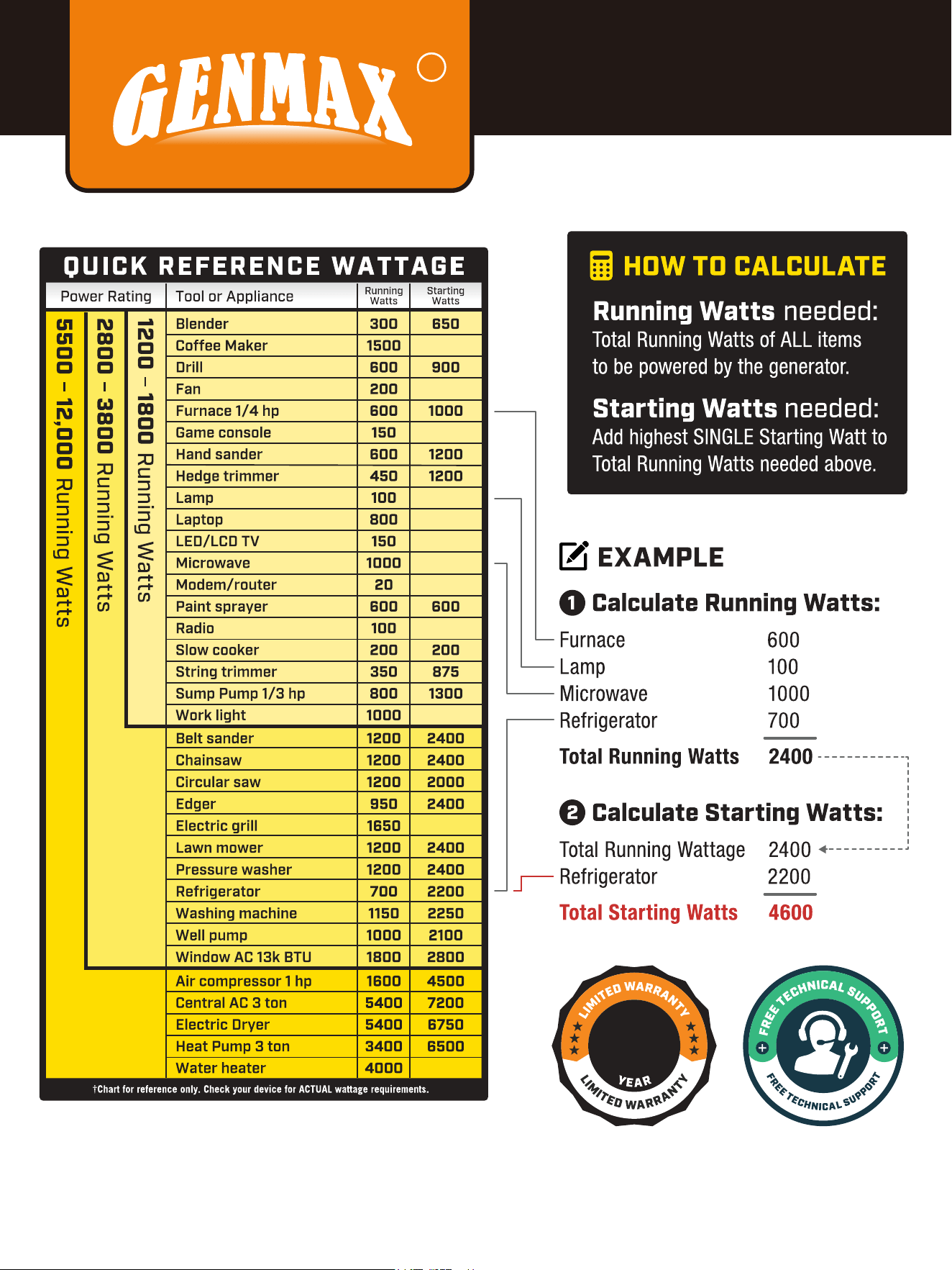
CHOOSING
A GENERATOR
1

37
In production management, based on orderly, efficient, scientific principles. trying to do as
better as possible in product design, development, production, inspection,etc. to make our
production can keep orderly . And will continue to make improvement to make sure that
keep the competitiveness.
Welcome friends at home and abroad to visit and guide, work together to create
brilliant.
You
Tube
f
+
R
Phone
866-960-2920
service@genmaxpower.com
Http://www.genmaxpower.com/
Caojie Industrial Park,Hechuan District,Chongqing
E-mail
FacebookLinkedinYouTube
6800.J64.GEM.02.00 V3
