

36” WALK BEHIND POWER TROWEL
SAVE THIS MANUAL: KEEP THIS MANUAL FOR SAFETY WARNINGS, PRECAUTIONS, ASSEMBLY,
OPERATING, INSPECTION, MAINTENANCE AND CLEANING PROCEDURES. WRITE THE
PRODUCT’S SERIAL NUMBER ON THE BACK OF THE MANUAL NEAR THE ASSEMBLY DIAGRAM
(OR MONTH AND YEAR OF PURCHASE IF PRODUCT HAS NO NUMBER).
OWNER’S MANUAL AND SAFETY INSTRUCTIONS
ITEM: 61024 (5.5HP) & 61025 (6.5HP)
FOR QUESTIONS PLEASE CALL OUR CUSTOMER SUPPORT: (909) 628 4900 MON-FRI 9AM TO 3PM PST

GENERAL SAFETY WARNINGS
Read all safety warnings and instructions. Failure to follow the warnings and instructions may
result in electric shock, fire and/or serious injury. Save all warnings and instructions for future
reference.
The warnings, precautions, and instructions discussed in this instruction manual cannot cover
all possible conditions and situations that may occur. It must be understood by the operator
that common sense and caution are factors which cannot be built into this product, but must be supplied by
the operator. Read carefully and understand all ASSEMBLY AND OPERATION INSTRUCTIONS
before operating. Failure to follow the safety rules and other basic safety precautions may result in
serious personal injury.
Read and understand all instructions. Failure to follow all instructions may result in serious injury
or property damage.
DO NOT allow persons to operate or assemble the product until they have read this manual and
have developed a thorough understanding of how it works.
DO NOT modify this product in any way. Unauthorized modification may impair the function and/or
safety and could affect the life of the product. There are specific applications for which the product
was designed.
Use the right tool for the job. DO NOT attempt to force small equipment to do the work of larger
industrial equipment. There are certain applications for which this equipment was designed. This
product will be safer and do a better job at the capacity for which it was intended. DO NOT use this
equipment for a purpose for which it was not intended.
Inspect the work area before each use. Keep work area clean, dry, free of clutter, and well-
lit. Cluttered, wet, or dark work areas can result in injury.
NEVER operate the machine with the belt guard missing. Exposed drive belt and pulleys
create potentially dangerous hazards that can cause serious injuries.
NEVER use the trowel around pop-ups in the concrete that are lower than the lowest ring on the
ring guard.
Keep children and bystanders away from the work area while operating the tool. DO NOT allow
children to handle the product.
ALWAYS close fuel valve on engines equipped with one when machine is not being operated.
ALWAYS operate machine with all safety devices and guards in place and in working order. DO NOT
modify or defeat safety devices. DO NOT operate machine if any safety devices or guards are missing or
inoperative.
Stay alert, watch what you are doing, and use common sense when operating the tool. DO NOT use
the tool while you are tired or under the influence of drugs, alcohol, or medication.
IMPORTANT SAFETY INFORMATION
1

Dress properly. DO NOT
IMPORT
wear loose clothing,
ANT SAFETY
dangling
INFORMA
objects, or jewellery
TION
. Keep your hair, clothing
and gloves away from moving parts. Loose clothes, jewelery, or long hair can be caught in moving parts.
Wear the proper personal protective equipment when necessary. Use ANSI Z87.1 compliant
safety goggles (not safety glasses) with side shields, or when needed, a face shield. Use a dust mask
in dusty work conditions. Also use non-skid safety shoes, hard-hat, gloves, dust collection systems,
and hearing protection when appropriate. This applies to all persons in the work area.
Always test the function of the engine control module before operating the trowel. DO NOT operate the
trowel if the engine control module is not functioning properly.
DANGER: Internal combustion engines present special hazards during operation and fueling. Read and
follow the warning instructions in the engine owner’s manual and the safety guidelines below. Failure
to follow the warnings and safety guidelines could result in severe injury or death.
Check for damaged parts before each use. Carefully check that the product will operate properly
and perform
its intended function. Replace damaged or worn parts immediately. Never operate the
product with a damaged part.
DO NOT run the machine indoors or in an enclosed area such as a deep trench unless adequate
ventilation, through such items as exhaust fans or hoses, is provided. Exhaust gas from the engine
contains poisonous carbon monoxide gas; exposure to carbon monoxide can cause loss of
consciousness and may lead to death.
WARNING: Poorly maintained equipment can become a safety hazard! In order for the equipment to
operate safely and properly over a long period of time, periodic maintenance and occasional repairs
are necessary.
DO NOT attempt to clean or service the machine while it is running. Rotating parts can cause severe
injury.
DO NOT crank a flooded engine with the spark plug removed on gasoline-powered engines. Fuel
trapped in the cylinder will squirt out the spark plug opening.
DO NOT test for spark on gasoline-powered engines if the engine is flooded or the smell of gasoline is
present. A stray spark could ignite the fumes.
DO NOT use gasoline or other types of fuels or flammable solvents to clean parts, especially in enclosed
areas. Fumes from fuels and solvents can become explosive.
DO NOT remove blades while the machine is hanging overhead.
ALWAYS support the machine securely before changing blades.
ALWAYS disconnect the spark plug on machines equipped with gasoline engines, before servicing, to
avoid accidental start-up.
ALWAYS keep the machine clean and labels legible. Replace all missing and hard-to-read labels.
Labels provide important operating instructions and warn of dangers and hazards.
ALWAYS handle blades carefully. The blades can develop sharp edges which can cause serious cuts.
IMPORTANT SAFETY INFORMATION
2

PARTS
3

PARTS
4

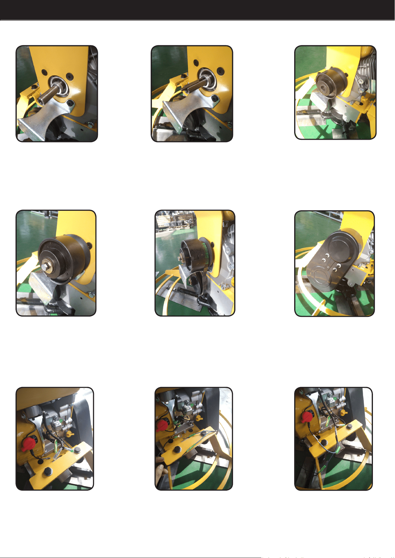
ASSEMBLY
STEP 1: Put #15 into the #14 hole. Make sure all the holes, including steel rope bracket hole of the
long handle and joint pipe hole.
STEP 2: Use two M10*80 retaining bolts (including #15) to lock the #15 onto the tube.
STEP 3: Put black limit bolt (including #15) to the boom of “U” groove to make sure the steel rope
(including #15) as long as it can be.
STEP 4: Let the steel rope screw (including in #15) go through the shi lever (including in #14) whole
and use the nut to lock it, make sure the nut has been thoroughly ghtened.
STEP 5: Use M10*120 external hexagon bolt (including in #15) and the locked aluminum nut
(including in #15) to lock #16 onto #15.
STEP 6: Take o 4 sets of ange nuts which have been installed on #14.
STEP 7: Install #17 to the #14 by using the M8 ange nuts.
STEP 8: Use #3 to lock #12 on the engine side cover (upper two holes).
STEP 9: Use #4 to lock #8 and #12 together onto the engine side cover (lower two holes).
STEP 10: Put #6 onto the engine sha.
STEP 11: Knock #5 into engine sha.
STEP 12: Put #9 onto the engine sha, make sure it is aligned with the key.
STEP 13: Use #7 to lock #9.
STEP 14: Install #11 into the #9 belt groove.
STEP 15: Use #1 and #2 to lock #13 onto #8.
STEP 16: Unplug the engine’s switch line.
STEP 17: Connect one of #10 wires with long handle ame-out wire (including in #15).
STEP 18: Connect another wire of #10 with engine’s switch line.
STEP 19: Connect another long handle ame-out wire (including in #15) with the engine’s body.
STEP 20: Lock the throle lever assembly (including in #17) onto the right handle.
5

ASSEMBLY
STEP 1: STEP 2: STEP 3:
STEP 4: STEP 5: STEP 6:
STEP 7:
STEP 8:
STEP 1: Put #15 into the #14 hole.
Make sure all the holes, including
steel rope bracket hole of the long
handle and joint pipe hole.
STEP 2: Use two M10*80
retaining bolts (including #15)
to lock the #15 onto the tube.
STEP 3: Put black limit bolt
(including #15) to the boom of
“U” groove to make sure the steel
rope (including #15) as long as it
can be.
STEP 4: Let the steel rope screw
(including in #15) go through
the shi lever (including in #14)
whole and use the nut to lock
it, make sure the nut has been
thoroughly ghtened.
STEP 5: Use M10*120 external
hexagon bolt (including in #15)
and the locked aluminum nut
(including in #15) to lock #16
onto #15.
STEP 6: Take o 4 sets of ange
nuts which have been installed on
#14.
STEP 9:
STEP 7: Install #17 to the #14 by
using the M8 ange nuts.
STEP 8: Use #3 to lock #12 on
the engine side cover (upper two
holes).
STEP 9: Use #4 to lock #8 and #12
together onto the engine side cover
(lower two holes).
6
ASSEMBLY
STEP 10: STEP 11:
STEP 12:
STEP 13: STEP 14: STEP 15:
STEP 16: STEP 17: STEP 18:
STEP 10: Put #6 onto the
engine sha.
STEP 11: Knock #5 into
engine sha.
STEP 12: Put #9 onto the
engine sha, make sure
it is aligned with the key.
STEP 13: Use #7 to lock
#9.
STEP 14: Install #11 into
the #9 belt groove.
STEP 15: Use #1 and #2
to lock #13 onto #8.
STEP 16: Unplug the
engine’s switch line.
STEP 17: Connect one
of #10 wires with long
handle ame-out wire
(including in #15).
STEP 18: Connect
another wire of #10 with
engine’s switch line.
7
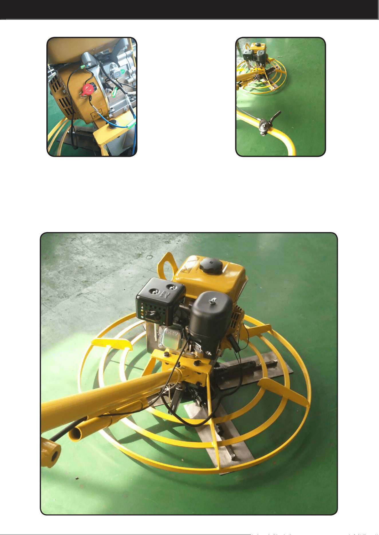
ASSEMBLY
STEP 19: STEP 20:
FINISHED ASSEMBLY SHOULD LOOK LIKE THIS.
STEP 19: Connect another
long handle ame-out wire
(including in #15) with the
engine’s body.
STEP 20: Lock the throle
lever assembly (including in
#17) onto the right handle.
8
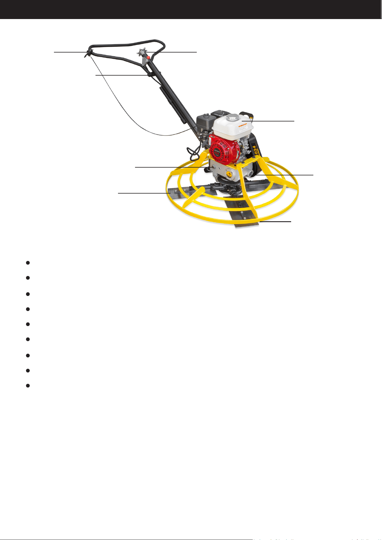
HIGH & LOW TURN WHEEL
ENGINE
OIL ENTRANCE
GUARD RING
THROTTLE
LEVER
ASSEMBLY
SAFE SWITCH
DECELERATION MACHINE
BLADE
BEFORE STARTING check the following:
Oil level in engine
Oil level in gearbox
Fuel level
Condition of air lter
Condition of fuel lines
Condition of trowel arms and blades
Condition of ring guards
Label descriptions
Handle height to suit operator
To prevent uncontrolled spinning of the trowel, the engine control module is designed to shut off the
engine under certain conditions. For example, if the operator loses his/her grip on the trowel, the
engine control module will sense that the machine is spinning and shut off the engine.
WARNING: DO NOT lift the trowel overhead with a oat pan attached, as the pan could fall off and
strike personnel working in the vicinity.
OPERATION
9

Oil level in gearbox
Condition of air lter
Condition of fuel lines
Condition of trowel arms and blades
Condition of ring guards
Label descriptions
Handle height to suit operator
1. Open the Flameout switch.
START UP
2. Open the Safe Switch to “ON”
3. Open the Fuel Switch
4. Close the Block Wind Door
5. Put the Oil Door Switch in the middle position
←
←
←
←
←
OPERATION
10
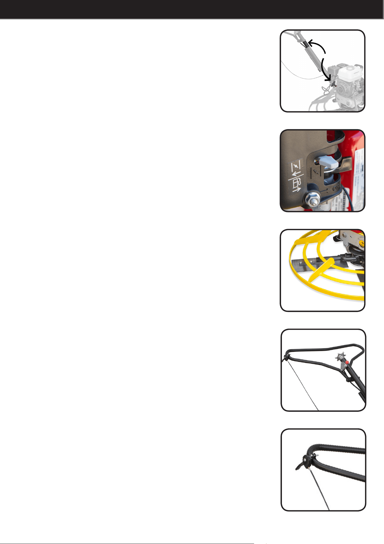
6. With one hand on the buttress handle, draw the engine
handle with the other.
←
7. Warm up the engine for three to ve minutes rst, then
open the block wind door.
8. Adjust the blades to the proper height.
9. With both hands hold the handle, then adjust the switch of
the Oil Door to the proper running sped for operation.
10. To turn off, put the switch of the Oil Door to “L”. Put the
Safe Switch to “Close”, then put the blades to level position.
OPERATION
11
WARNING: ALWAYS test the function of the engine control module before operating the trowel. DO NOT
operate the trowel if the engine control module is not functioning properly.
Choose correct blade type and attach blades to trowel arms. Do not mix oat or nish blades with
combination blades.
CAUTION: DO NOT attempt to adjust handle height on the trowel while it is running.
WARNING: Allow the mufer to cool before cleaning or servicing the machine. A hot mufer could ignite
the fuel and start a re.
WARNING: Personnel other than the trowel operator should not be allowed in the work area, as severe
injury can occur from contact with operating trowel blades.
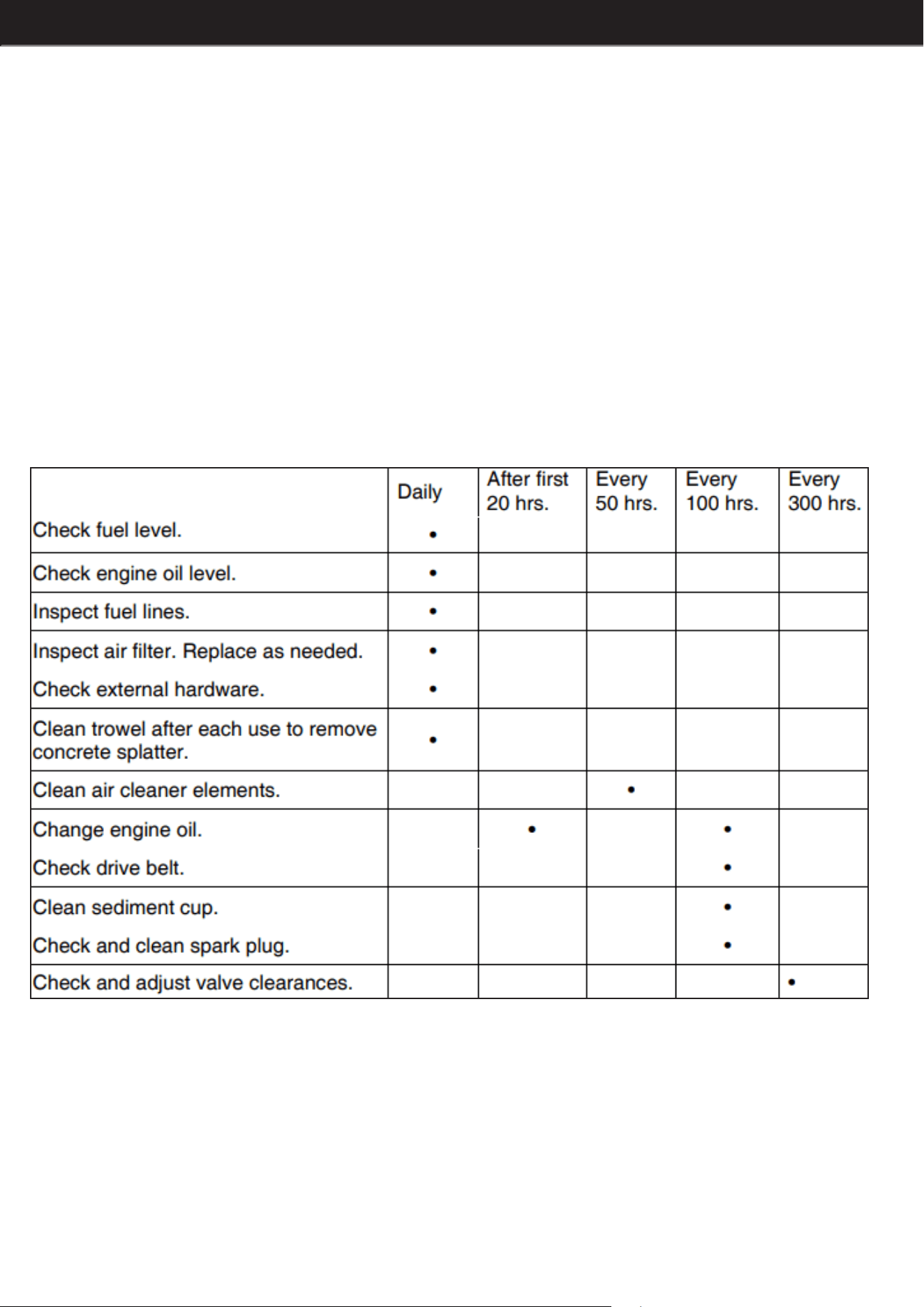
MAINTENANCE The chart below lists basic machine and engine maintenance.
Perform initially after rst 20 hours of operation.
In the interests of environmental protection, place a plastic sheet and a container under the machine
to collect any liquid which drains off. Dispose of this liquid in accordance with environmental protection
legislation.
OPERATION
12
ENGINE OIL:
Drain oil while the engine is still warm.
Remove the oil ll plug and drain cap to drain oil.
Install drain cap.
Fill the engine crankcase with recommended oil up to the level of the plug opening.
AIR CLEANER:
Service air cleaner frequently to prevent carburetor malfunction. NEVER run engine without air cleaner.
Severe engine damage will occur. NEVER use gasoline or other types of low ash point solvents for
cleaning the air cleaner. A re or explosion could result.
Remove air cleaner cover. Remove both elements and inspect them for holes or tears. Replace
damaged elements.
Wash foam element (b) in solution of mild detergent and warm water. Rinse thoroughly in clean water.
Allow element to dry thoroughly. Soak element in clean engine oil and squeeze out excess oil.
Tap paper element lightly to remove excess dirt. Replace paper element if it appears heavily soiled.
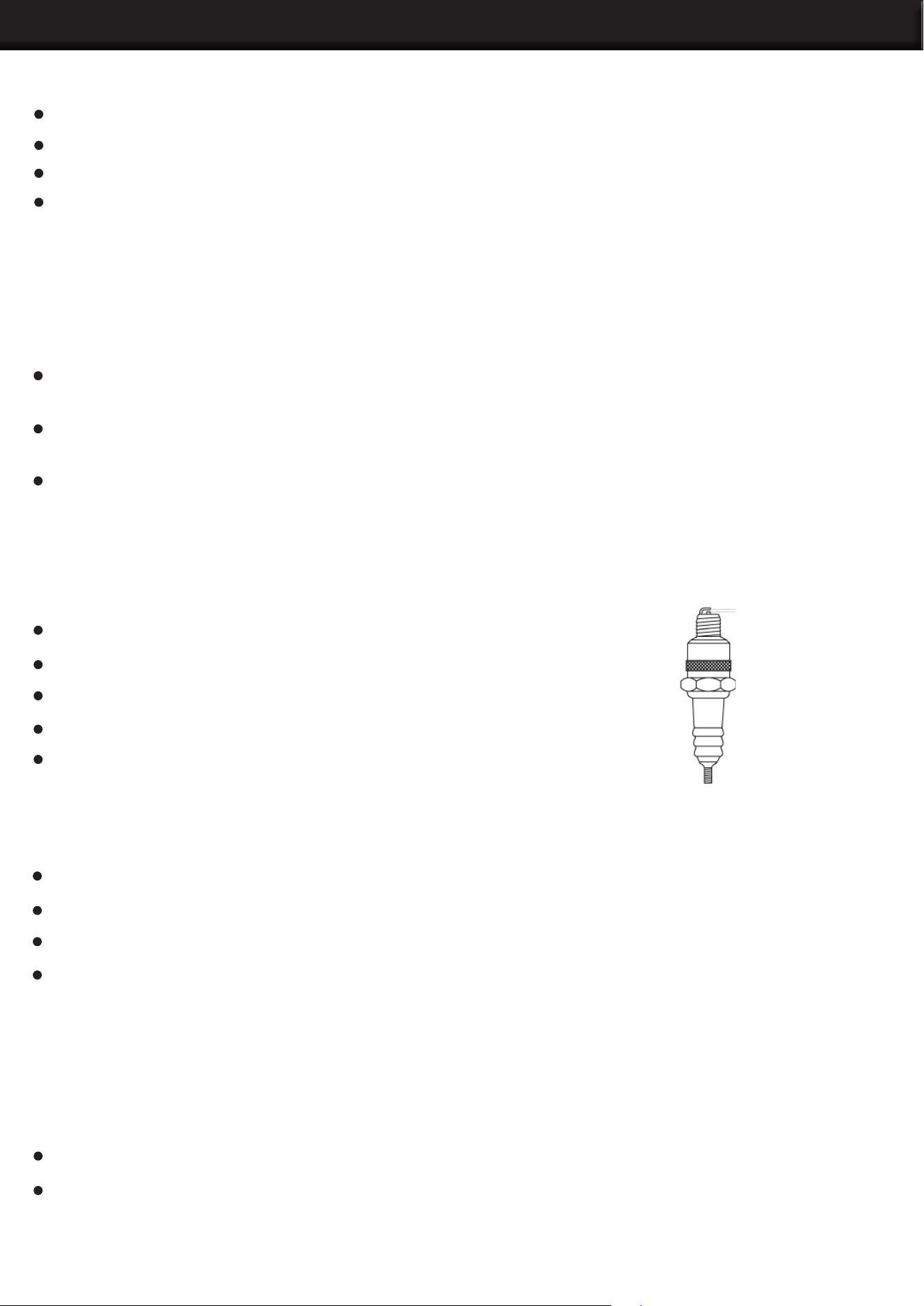
SPARK PLUG:
Clean or replace the spark plug as needed to ensure proper operation. CAUTION A loose spark plug can
become very hot and may cause engine damage.
Remove the spark plug and inspect it.
Replace the spark plug if the insulator is cracked or chipped.
Clean the spark plug electrodes with a wire brush.
Set the electrode gap.
Tighten the spark plug securely.
CLEANING SEDIMENT CUP:
Turn the fuel valve off.
Remove the sediment cup and the O-ring.
Wash both thoroughly in a non-ammable solvent. Dry and reinstall them.
Turn the fuel valve on and check for leaks.
ADJUSTING IDLE SPEED:
WARNING: Remove the drive belt before making any adjustment to the carburetor. The blades will engage
unless the belt is removed from the machine.
Start the engine and allow it to warm up to normal operating temperature.
Turn the throttle stop screw in to increase speed, out to decrease speed. Make sure the throttle lever is
touching the stop screw before measuring rpm.
MAINTENANCE
13
BELT REPLACEMENT:
The trowel is equipped with a self-adjusting clutch. This clutch automatically tightens the belt and
compensates for belt wear. Replace the belt if the clutch can no longer tighten belt enough to engage
gearbox without slipping. To replace the drive belt:
Disconnect the spark plug lead. WARNING: To avoid accidental starting of the engine, always disconnect
the spark plug lead before working on machine.
Loosen the screws and remove the belt guard.
Slowly turn the pulley and roll the belt off.
Install the new belt.
Reattach the belt guard with washers and screws.
STORAGE:
If trowel is being stored for more than 30 days:
Change engine oil.
Drain fuel from engine.
Remove spark plug and pour 15 ml (½ ounce) of SAE 30 engine oil into the cylinder. Replace spark plug
and crank engine to distribute oil.
Clean dirt from cylinder, cylinder head ns, blower housing, rotating screen, and mufer areas.
Cover trowel and engine and store in a clean, dry area.
MAINTENANCE
14

PRECAUTIONS
The trowel manufacturer has no direct control over machine application, operation, inspection, lubrication,
or maintenance. Therefore, it is your responsibility to use good safety practices in these areas.
DO NOT use the trowel for any purpose other than its intended purposes or applications.
Know the capabilities and limitations of the trowel.
Walk around the trowel. Carefully inspect for evidence of physical damage, such as cracks, bends,
or deformation of plates and welds. Check for loose, broken or missing parts on the trowel, including
brackets, vibration isolators, nuts and bolts. Hardware should be replaced with original equipment
manufacturer’s (OEM) parts, and should be properly tightened to the manufacturer’s recommendations.
NEVER check for hydraulic leaks with your hand. Hydraulic systems are under high pressure and leaks
in these systems can penetrate the skin which can result in serious injury or even death. ALWAYS use
a piece of cardboard or wood when looking for hydraulic leaks.
Exhaust from the engine contains poisonous carbon monoxide gas that is not easily detected as it is
colorless and odorless. Exposure to carbon monoxide can cause loss of consciousness and may lead
to death! DO NOT operate your trowel indoors or in an enclosed area unless adequate ventilation is
provided. Ensure that permissible carbon monoxide levels are monitored and not exceeded.
The mufer, exhaust pipes and other engine parts will become hot during operation and will remain hot
for a while after shut down. DO NOT touch until allowed to sufciently cool. DO NOT allow debris, rags,
paper, or leaves to accumulate around these areas.
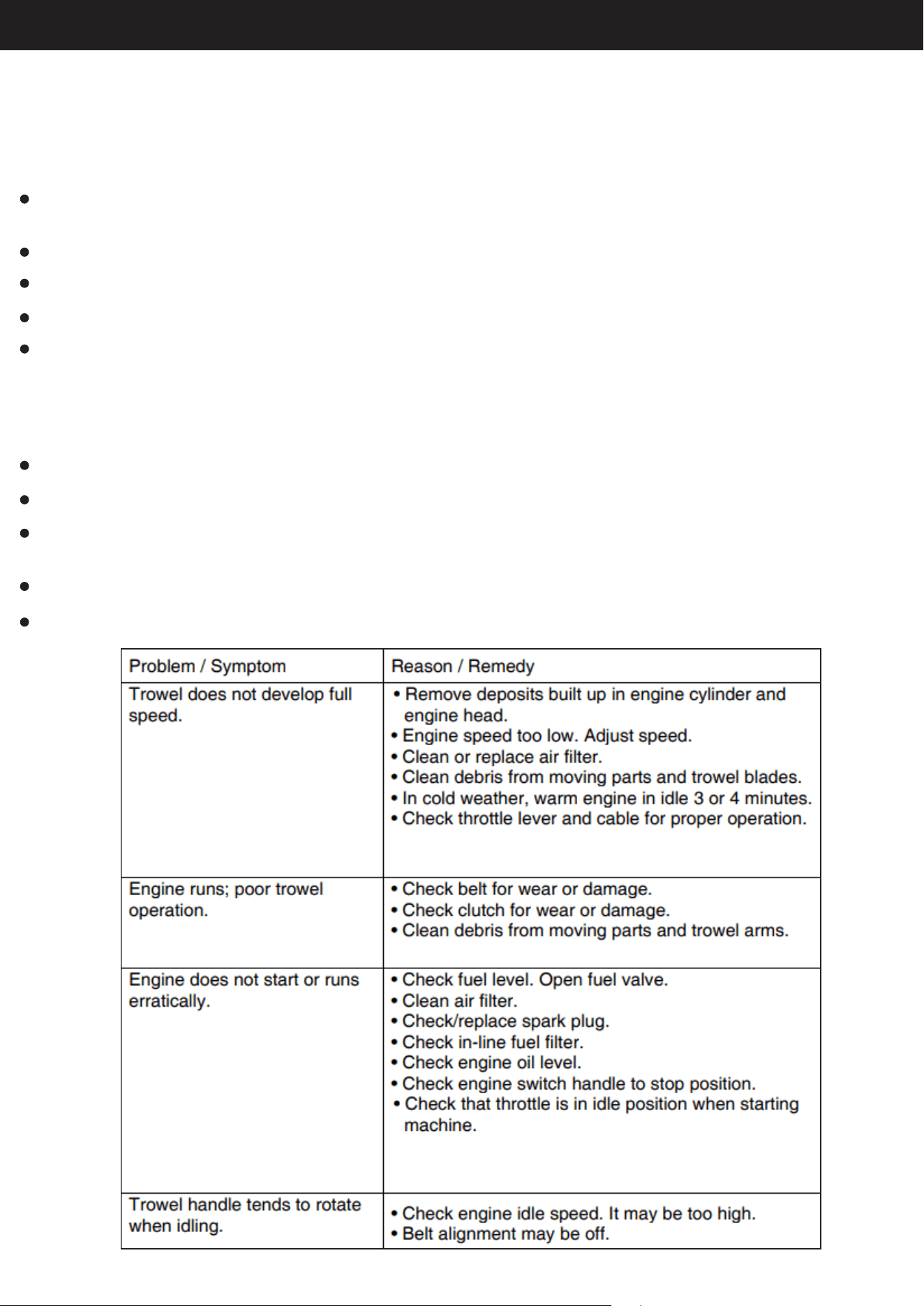
MAINTENANCE AND TROUBLESHOOTING
NEVER operate a trowel with a damaged or worn electrical cord. When using an extension cord, be sure
to use one heavy enough to carry the current load. When trowel is used outdoors, use only extension
cords that are marked for outdoor use.
15
16

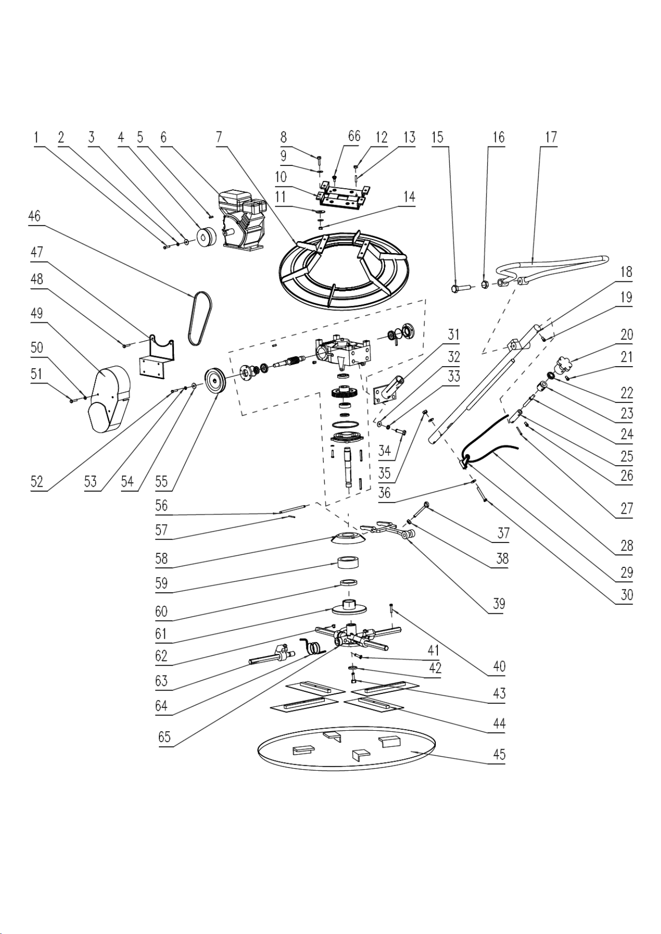
61024/61025EXPLODING DRAWING
NO. SIZE QTY NO. SIZE QTY
1 External Hexagon Bolt M8*40 1PC 39 Shift Lever 1PC
2 Spring Gasket Ø8 1PC 40 External Hexagon Bolt M8*40 8PCS
3 Tapered Flat Gasket Ø8*30 1PC 41 External hexagon bolt M10*25 4PCS
4 Clutch Assembly 1PC 42 Gasket 1PC
5 Key 5*50 1PC 43 Inner Hexagon Bolt M12*30 1PC
6 Engine 1PC 44 Blade 4PCS
7 Boot Cap 1PC 45 Disc Pan 1PC
8 External Hexagon Bolt M12*40 4PCS 46 Belt 1PC
9 Flat Gasket Ø12 8PCS 47 Belt Cover Bracket 1PC
10 Supporting Seat 1PC 48 Round Head Bolt M8*16 2PCS
11 Gasket M12*40*4 4PCS 49 Belt Cover 1PC
12 Non-slip Nuts M8 4PCS 50 Flat Gasket Ø6 4PCS
13 Bolt M8*40 4PCS 51 Inner Hexagon Bolt M6*16 4PCS
14 Locked Nut M12 4PCS 52 Inner Hexagon Bolt M8*20 1PC
15 External Hexagon Bolt M16*120 1PC 53 Spring Gasket Ø8 1PC
16 Nut M16 2PCS 54 Enlarged Flat Gasket Ø8*30 1PC
17 Handle 1PC 55 Pulley 1PC
18 Control Lever 1PC 56 Gear Shift Lever 1PC
19 Inner Hexagon bolt M8*10 1PC 57 Cotter Ø3*30 2PCS
20 Hand Wheel 1PC 58 Salver 1PC
21 Locked Bolt M8*12 1PC 59 Bearing Location Ring 1PC
22 Gear 51204 1PC 60 Plane Bearing 51209 1PC
23
Gear Sheath
1PC 61
Sliding Plate
1PC
24 Adjust Screw 1PC 62 Intake Oil Hole 4PCS
25 Adjust Nut 1PC 63 Blade Shaft and The Elbow 4PCS
26 Inner Hexagon Bolt M8*10 2PCS 64 Torsional Spring 4PCS
27 Pin Ø6*40 1PC 65 Cross Shaft 1PC
28 Cable Accelerator 1PC 66 Countersunk Head Bolt M10*20 4PCS
29 Cable Bracket 1PC A Gear Box 1PC
30 External Hexagon Bolt M10*80 2PCS
31
Intubation Seat
1PC
32 Flat Gasket Ø10 4PCS
33 Spring Gasket Ø10 4PCS
34 External Hexagon Bolt M10*25 4PCS
35 Nut M10 2PCS
36 Flat Gasket Ø10 4PCS
37 Swing Bolt M10*90 1PC
38 Nut M10 1PC
17

Batteries produce explosive gases. Keep open ame or sparks away. See the manufacturer’s instructions
when servicing the batteries, when using jumper cables, or when using a battery charger. Use a ashlight
to check battery electrolyte level. ALWAYS check with engine stopped. Battery electrolyte is poisonous.
It is strong enough to burn your skin, eat holes in clothing, and can cause blindness if splashed into eyes.
Always wear eye and face protection.
Be sure the trowel is properly lubricated. See that the fuel, lubricating oil, coolant and hydraulic reservoirs
are lled to the proper levels with the correct uids.
NEVER overll fuel tanks or uid reservoirs. In the event of a fuel spill, DO NOT attempt to start the engine
until the fuel residue has been completely wiped up, and the area surrounding the engine is dry. Replace
fuel cap securely after refuelling.
PLEASE READ THE FOLLOWING CAREFULLY
Record Product’s Serial Number Here:
Note: If product has no serial number, record month and year of purchase instead.
Note: Some parts are listed and shown for illustration purposes only and are not available
individually as replacement parts.
THE MANUFACTURER AND/OR DISTRIBUTOR HAS PROVIDED THE PARTS LIST AND ASSEMBLY
DIAGRAM IN THIS MANUAL AS A REFERENCE TOOL ONLY. NEITHER THE MANUFACTURER OR
DISTRIBUTOR MAKES ANY REPRESENTATION OR WARRANTY OF ANY KIND TO THE BUYER THAT
HE OR SHE IS QUALIFIED TO MAKE ANY REPAIRS TO THE PRODUCT, OR THAT HE OR SHE IS
QUALIFIED TO REPLACE ANY PARTS OF THE PRODUCT. IN FACT, THE MANUFACTURER AND/OR
DISTRIBUTOR EXPRESSLY STATES THAT ALL REPAIRS AND PARTS REPLACEMENTS SHOULD BE
UNDERTAKEN BY CERTIFIED AND LICENSED TECHNICIANS, AND NOT BY THE BUYER. THE BUYER
ASSUMES ALL RISK AND LIABILITY ARISING OUT OF HIS OR HER REPAIRS TO THE ORIGINAL
PRODUCT OR REPLACEMENT PARTS THERETO, OR ARISING OUT OF HIS OR HER INSTALLATION
OF REPLACEMENT PARTS THERETO.
DISCLAIMER
PRODUCT MADE IN CHINA
18