1

1
GENERAL SAFETY WARNINGS
Read all safety warnings and instructions. Failure to follow the warnings and instructions may
result in electric shock, fire and/or serious injury. Save all warnings and instructions for future
reference.
The warnings, precautions, and instructions discussed in this instruction manual cannot cover
all possible conditions and situations that may occur. It must be understood by the operator
that common sense and caution are factors which cannot be built into this product, but must be supplied by
the operator. Read carefully and understand all ASSEMBLY AND OPERATION INSTRUCTIONS
before operating. Failure to follow the safety rules and other basic safety precautions may result in
serious personal injury.
Read and understand all instructions. Failure to follow all instructions may result in serious injury
or property damage.
DO NOT allow persons to operate or assemble the product until they have read this manual and
have developed a thorough understanding of how it works.
DO NOT modify this product in any way. Unauthorized modification may impair the function and/or
safety and could affect the life of the product. There are specific applications for which the product
was designed.
Use the right tool for the job. DO NOT attempt to force small equipment to do the work of larger
industrial equipment. There are certain applications for which this equipment was designed. This
product will be safer and do a better job at the capacity for which it was intended. DO NOT use this
equipment for a purpose for which it was not intended.
Inspect the work area before each use. Keep work area clean, dry, free of clutter, and well-
lit. Cluttered, wet, or dark work areas can result in injury.
NEVER operate the machine with the belt guard missing. Exposed drive belt and pulleys
create potentially dangerous hazards that can cause serious injuries.
NEVER use the trowel around pop-ups in the concrete that are lower than the lowest ring on the
ring guard.
Keep children and bystanders away from the work area while operating the tool. DO NOT allow
children to handle the product.
ALWAYS close fuel valve on engines equipped with one when machine is not being operated.
ALWAYS operate machine with all safety devices and guards in place and in working order. DO NOT
modify or defeat safety devices. DO NOT operate machine if any safety devices or guards are missing or
inoperative.
Stay alert, watch what you are doing, and use common sense when operating the tool. DO NOT use
the tool while you are tired or under the influence of drugs, alcohol, or medication.

Dress properly. DO NOT wear loose clothing, dangling objects or jewelry. Keep y
our hair, clothing
and gloves away from moving parts. Loose clothes, jewelery, or long hair can be caught in moving parts.
Wear the proper personal protective equipment when necessary. Use ANSI Z87.1 compliant
safety goggles (not safety glasses) with side shields, or when needed, a face shield. Use a dust mask in
dusty work conditions. Also use non-skid safety shoes, hard-hat, gloves, dust collection systems,
and hearing protection when appropriate. This applies to all persons in the work area.
Always test the function of the engine control module before operating the trowel. DO NOT operate the
trowel if the engine control module is not functioning properly.
DANGER: Internal combustion engines present special hazards during operation and fueling. Read and
follow the warning instructions in the engine owner’s manual and the safety guidelines below. Failure
to follow the warnings and safety guidelines could result in severe injury or death.
Check for damaged parts before each use. Carefully check that the product will operate properly
and perform its intended function. Replace damaged or worn parts immediately. Never operate the
product with a damaged part.
DO NOT run the machine indoors or in an enclosed area such as a deep trench unless adequate
ventilation, through such items as exhaust fans or hoses, is provided. Exhaust gas from the engine
contains poisonous carbon monoxide gas; exposure to carbon monoxide can cause loss of
consciousness and may lead to death.
WARNING: Poorly maintained equipment can become a safety hazard! In order for the equipment to
operate safely and properly over a long period of time, periodic maintenance and occasional repairs
are necessary.
DO NOT attempt to clean or service the machine while it is running. Rotating parts can cause severe
injury.
DO NOT crank a flooded engine with the spark plug removed on gasoline-powered engines. Fuel
trapped in the cylinder will squirt out the spark plug opening.
DO NOT test for spark on gasoline-powered engines if the engine is flooded or the smell of gasoline is
present. A stray spark could ignite the fumes.
DO NOT use gasoline or other types of fuels or flammable solvents to clean parts, especially in enclosed
areas. Fumes from fuels and solvents can become explosive.
ALWAYS disconnect the spark plug on machines equipped with gasoline engines, before servicing, to
avoid accidental start-up.
ALWAYS keep the machine clean and labels legible. Replace all missing and hard-to-read labels.
Labels provide important operating instructions and warn of dangers and hazards.
ALWAYS handle blades carefully. The blades can develop sharp edges which can cause serious cuts.
2
1
2 3 4
5
6 7 8
9
10 11 12
13 14 1615
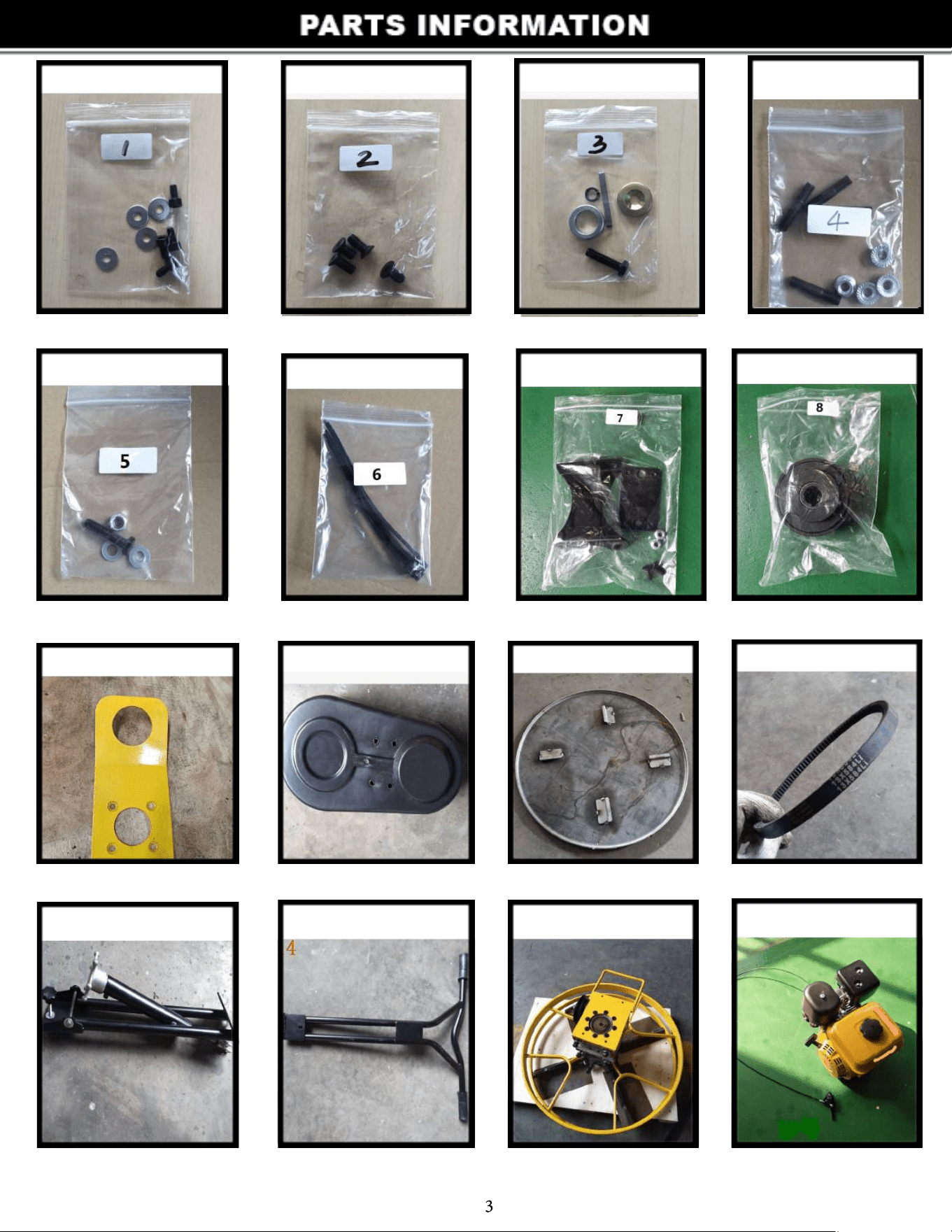
Part # 1 Part # 2 Part # 3 Part # 4
Part # 5 Part # 6 Part # 7 Part # 8
Part # 9 Part # 10 Part # 11 Part # 12
Part # 13 Part # 14 Part # 15 Part # 16
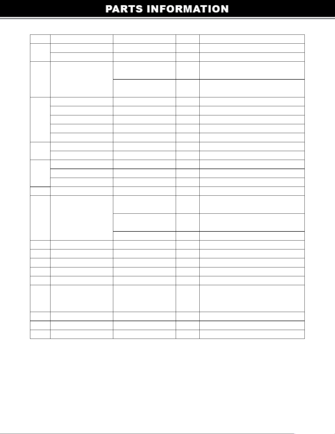
Code
Name
Type
Qty
4pcs
4pcs
2pcs
each
2pcs
each
1pc
1pc
1pc
1pc
1pcs
4pcs
4pcs
1pc
1pc
2pcs
4pcs
2pcs
1set
1pc
1pc
1pc
1pc
1set
1set
1set
1set
Note
1
2
3
4
5
7
6
8
9
10
11
12
15
14
13
16
4
6*18*2
M6*12
5/16-24-38
Ø8
8*30
4.78*50
Ø20*8
M8*40
M8
M8*35
M8
Ø8
M6 flange nut
19.05
A-584
5/16-24-16/20
M8*16/20
Flat gasket
Hexagon screw
Shaft head bolt
Spring gasket
Tapered flat gasket
Flat key
Clutch adjusting pad
Double end bolt
Flange nut
Outer hexagon bolt
Locknut
Flat gasket
Ribbon
Clutch assembly
Lifting hook
Belt cover
Disc pan
V belt
Lower handle
Upper handle
Main body
Engine
Countersunk head
hexagon screw
Belt cover
bracket assembly
Z plate and
connecting plate
M6*16Countersunk
head screw
2pcs
2pcs
If with Honda engine
(for sku: 61042-1)
If with Loncin engine
(for sku: 61041-1)
Including lifting screw,upper handle
retaining bolt M8*120(1pc)
and M8*50 bakelite bolt etc.
Including throttle lever assembly
5
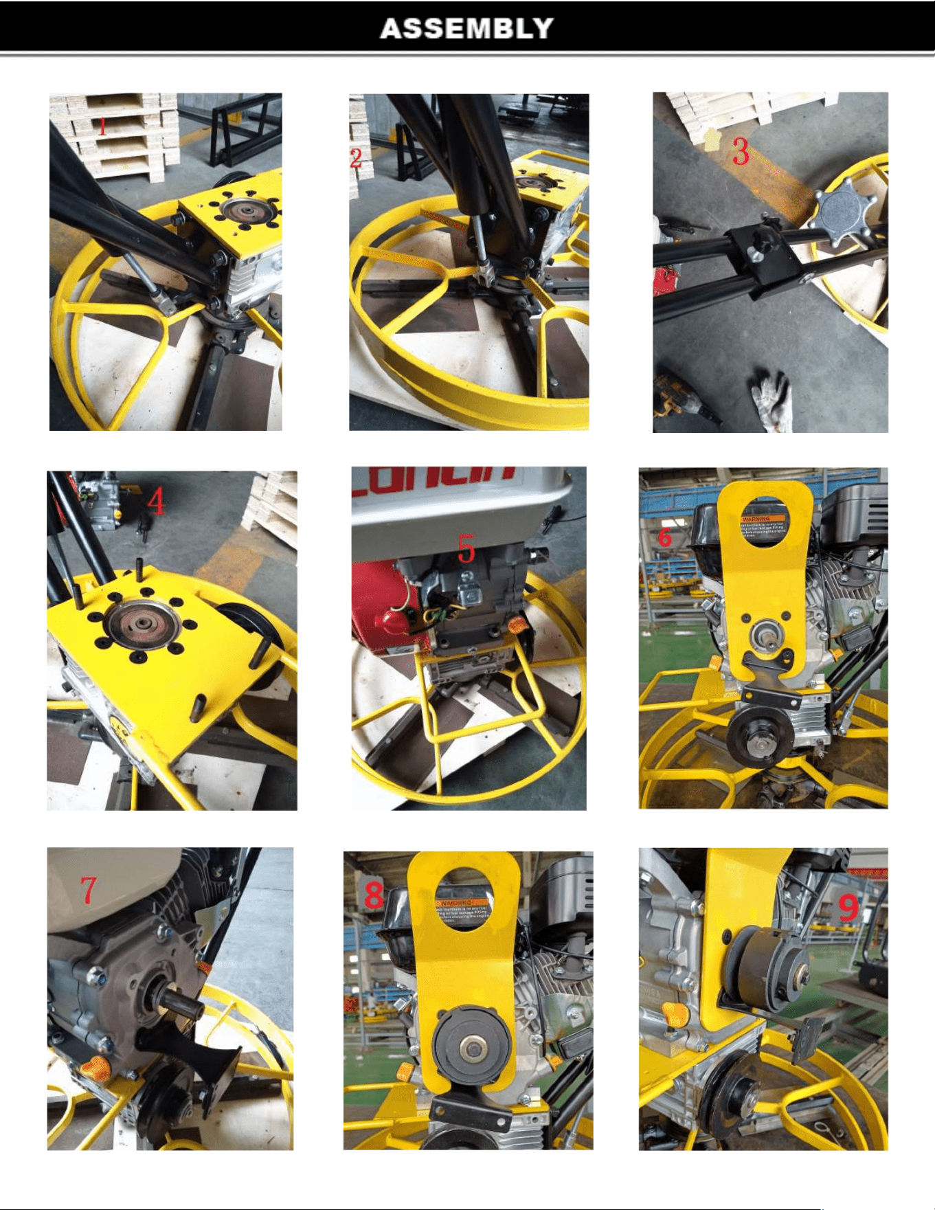
STEP 1 STEP 2 STEP 3
STEP 4 STEP 5 STEP 6
STEP 7 STEP 8 STEP 9
6
1. Use M10 nut,spring gasket and flat gasket to fix No.13 on the No.15.(nut and flat spring gasket are on the
No.15 already).
2. Use No.5 to lock U-shaped part on the No.15(U-shaped part is on No.13 already).
3. Use M8x120 out hexagon bolt and nut to connect No.14 and No.13.Use M8x50 bakelite bolt to lock
it.(M8x120 bolt,nut and M8x50 bakelite bolt are all with No.13)
4. Twist No.4 double end bolt on the No.15.
5. Put No.16 engine on the engine support plate(No.15).Use No.4 flange nut to fix it.
6. Use No.2 bolt which is 20mm length to fix No.9 and No.7 on the engine side cover by locking two nether
holes.Use No.2 bolt which is 16mm length to fix No.9 on the engine side cover by locking two upper holes.
7. Put No.3 clutch adjusting pad on the engine shaft to adjust the gap.Put No.3 flat key into the engine shaft
groove.(Notice:put the key into the head of the shaft,then go into the groove with clutch.See Step 8)
8. Put No.8 clutch into the groove.Use No.3 shaft head bolt,spring gasket and tapered flat gasket to fix it.
9. Use No.7 M6*16 countersunk head screw and M6 flange nut to fix connecting plate on the Z plate.
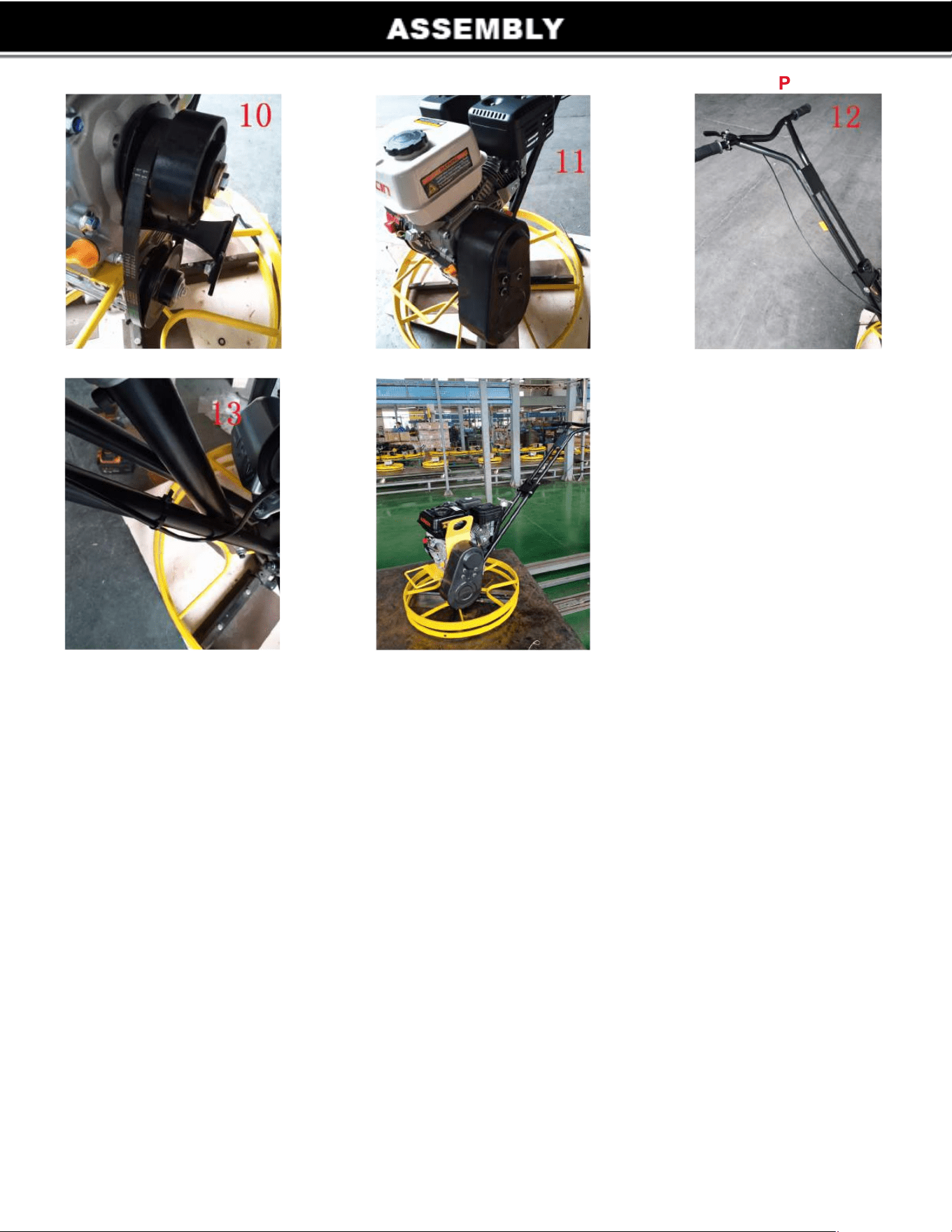
10. Install No.12 onto the pulley belt groove.
11. Use No.1 to fix No.10 belt cover on No.7.
12. Fix the throttle lever assy(including in No.16) on the handle.
13. Use No.6 to strap the throttle lever assy on the handle.
STEP 10 STEP 11
STEP 13
PSTE 12
7

8
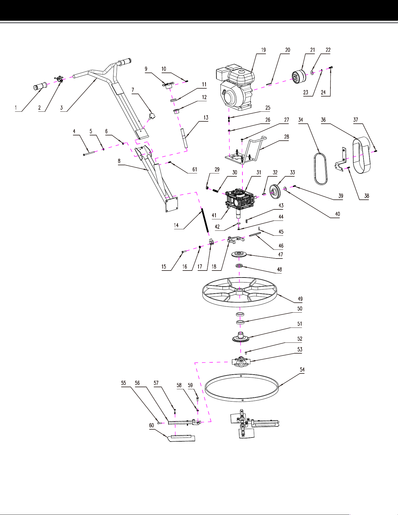
61041 Exploding Drawing
Part NO.
E-1
E-2
E-3
E-4
E-5
E-6
E-7
E-8
E-9
E-10
E-11
E-12
E-13
E-14
E-15
E-16
E-17
E-18
E-19
E-20
E-21
E-22
E-23
E-24
E-25
E-26
E-27
E-28
E-29
E-30
E-31
E-32
E-33
E-34
E-35
E-36
E-37
E-38
E-39
E-40
E-41
E-42
E-43
E-44
E-45
E-46
E-47
E-48
E-49
E-50
E-51
E-52
E-53
E-54
E-55
E-56
E-57
E-58
E-59
E-60
E-61
Type
M8*110
Ø8
M8
M8*50
M8*12
51204
M10
M8*35
M8
5*40
8*30
Ø8
M8*40
M8*40
M8
M8*20
M10
M10*40
6*30
M8*16
M8*16
M6*20
6*24
M8*25
M8*30
Ø3
51107
6908
M8*20
M8*20
M6*35
M8
M8*30
M8*10
Qty
2pcs
1set
1pc
1pc
2pcs
1pc
1pc
1pc
1pc
1pc
1pc
1pc
1pc
1pc
1pc
1pc
1pc
1pc
1set
1pc
1set
1pc
1pc
1pc
4pcs
4pcs
8pcs
1pc
4pcs
4pcs
1set
1pc
1pc
1pc
1pc
1pc
2pcs
2pcs
1pc
1pc
2pcs
1pc
1pc
1pc
2pcs
1pc
1pc
1pc
1pc
2pcs
1pc
4pcs
1pc
1pc
1pc
4sets
8pcs
4pcs
4pcs
4pcs
1pc
Description
Plastic Handle
Throttle Switch Assembly
Control Handle
External Hexagon Bolt
Flat Gasket
Locked Nut
Bakelite Plum Flower Bolt
Armrest
Aluminum Lift Handle
Locked Bolt
Plane Bearing
Aluminum Fixing Sleeve
Lift Screw
Lifting rod connector
External Hexagon Bolt
Locked Nut
Lifting rod connector
Shift Lever
Engine
Key
Clutch Assembly
Enlarged Flat Gasket
Spring Gasket
External Hexagon Bolt
Bolt
Flange Nut
Inner Hexagon Bolt
Supporting Seat
Locked Nut
Locked Bolt
Worm-Gear Case
Key
Pulley
Belt
Belt Cover Bracket
Belt Cover
Inner Hexagon Bolt
Round Head Bolt
Inner Hexagon Bolt
Enlarged Flat Gasket
Shift Fork of Support Block
Gasket
Key
Countersunk Head Bolt
Cotter
Shift Fork of Pin
Shift Fork Disc
Plane Bearing
Shield
Bearing
Shield Shaft Seat
Countersunk Head Bolt
Cross Shaft
Blade Retainer
Inner Hexagon Bolt
Blade Shaft Assembly
External Hexagon Bolt
Nut
Step Bolt
Blade
Inner Hexagon Bolt
9