RUSH MH 8 Mini Profile
User Manual

© 2016 Martin Professional ApS. Information subject to change without notice. Martin Professional
and all affiliated companies disclaim liability for any injury, damage, direct or indirect loss,
consequential or economic loss or any other loss occasioned by the use of, inability to use or
reliance on the information contained in this manual. The RUSH name, RUSH logo, Martin name
and Martin logo and all other trademarks in this document pertaining to services or products by
Martin Professional or its affiliates and subsidiaries are trademarks owned or licensed by Martin
Professional or its affiliates or subsidiaries.
Martin Professional • Olof Palmes Allé 18 • 8200 Aarhus N • Denmark • www.martin.com
Manual: Revision A

Table of contents
Safety information .............................................................................................. 4
Introduction ........................................................................................................ 8
Before using the product for the first time ...................................................... 8
Physical installation ........................................................................................... 9
Fastening the fixture to a flat surface ............................................................. 9
Mounting the fixture on a truss ....................................................................... 9
AC power ......................................................................................................... 11
Fixture overview ............................................................................................... 12
Control data link ............................................................................................... 13
Tips for reliable data transmission ............................................................... 13
Connecting the data link ............................................................................... 13
Fixture setup .................................................................................................... 14
Using the control menus .............................................................................. 14
DMX addressing ........................................................................................... 14
Behavior without DMX (DMX State) ............................................................. 14
Stand-alone settings .................................................................................... 15
Pan/tilt inversion ........................................................................................... 16
Dimmer settings ........................................................................................... 17
Backlight ....................................................................................................... 18
Fixture time ................................................................................................... 18
Reset ............................................................................................................ 18
Fan mode ..................................................................................................... 18
Home position adjustment (offsets menu) ................................................... 19
Effects .............................................................................................................. 20
Pan and tilt ................................................................................................... 20
Strobe effects ............................................................................................... 20
Electronic dimming ....................................................................................... 20
Colors ........................................................................................................... 21
Gobos ........................................................................................................... 21
Maintenance .................................................................................................... 22
Cleaning ....................................................................................................... 22
Replacing the primary fuse .......................................................................... 23
Service and repairs ...................................................................................... 23
DMX protocol ................................................................................................... 24
Control menus .................................................................................................. 27
Troubleshooting ............................................................................................... 29
Specifications ................................................................................................... 30
4 RUSH™ MH 8 Mini Profile User Manual
Safety information
WARNING!
Read the safety precautions in this manual before installing,
operating or servicing this product.
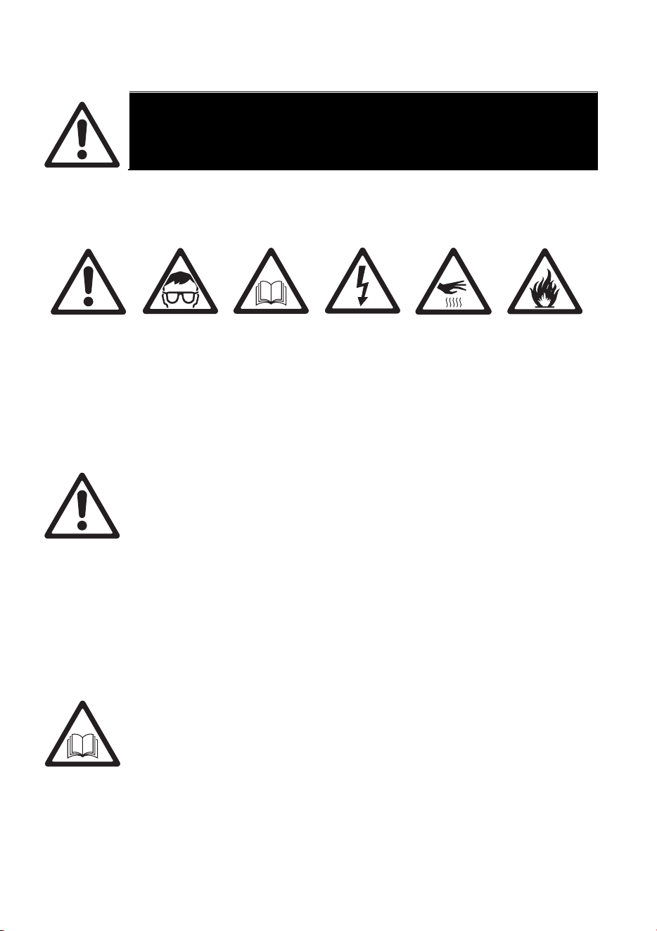
The following symbols are used to identify important safety information on the
product and in this manual:
Warning!
Safety
hazard. Risk
of severe
injury or
death.
Warning!
Powerful
light
emission.
Risk of eye
injury.
Warning!
See user
manual for
important
safety
information.
Warning!
Hazardous
voltage.
Risk of
lethal or
severe
electric
shock.
Warning!
Hot
surfaces.
Warning!
Fire hazard.
Warning! Risk Group 2 product according to EN 62471.
Possibly hazardous radiation emitted from this product. May be
harmful to the eyes. Do not stare at operating lamp and do not
view the light output with optical instruments or any device that
may concentrate the beam.
This lighting fixture is for professional use only and must be
installed by a qualified technician. It is not for household use. It
presents risks of severe injury or death due to fire hazards,
electric shock and falls. It produces a powerful, concentrated
beam of light that can create a fire hazard or a risk of eye injury
if the safety precautions below are not followed.
Install, operate and service Martin™ products only as directed
in their user manuals, or you may create a safety hazard or
cause damage that is not covered by product warranties.
Follow the safety precautions listed below and observe all
warnings in this manual and printed on the product. Keep this
user manual for future use.
For the latest user documentation and other information for this
and all Martin™ products, please visit the Martin website at
RUSH™ MH 8 Mini Profile User Manual 5
http://www.martin.com
If you have any questions about how to install, operate or
service the fixture safely, please contact your Martin™
distributor (see www.martin.com/distributors for details) or call
the Martin™ 24-hour service hotline on +45 8740 0000, or in
the USA on 1-888-tech-180.
Respect all locally applicable laws, codes and regulations when
installing, operating or servicing the fixture.
Protection from electric shock
Do not expose the fixture to rain or moisture.
Disconnect the fixture from AC power before carrying out any
installation or maintenance work and when the fixture is not in
use.
Ensure that the fixture is electrically connected to ground
(earth).
Use only a source of AC power that complies with local building
and electrical codes and has both overload and ground-fault
(earth-fault) protection.
Socket outlets or external power switches used to supply the
fixture with power must be located near the fixture and easily
accessible so that the fixture can easily be disconnected from
power.
Replace defective fuses with ones of the specified type and
rating only.
Isolate the fixture from power immediately if the power plug or
any seal, cover, cable, or other component is damaged,
defective, deformed, wet or showing signs of overheating. Do
not reapply power until repairs have been completed
Before using the fixture, check that all power distribution
equipment and cables are in perfect condition and rated for the
electrical requirements of all connected devices.
6 RUSH™ MH 8 Mini Profile User Manual
Protection from burns and fire
Do not operate the fixture if the ambient temperature (T
a
)
exceeds 40° C (104° F).
The surface of the product casing can reach up to 45° C
(113° F) during operation. Avoid contact by persons and
materials. Allow the fixture to cool for at least 10 minutes before
handling.
Keep flammable materials well away from the fixture. Keep all
combustible materials (e.g. fabric, wood, paper) at least 100
mm (4 in.) away from the fixture head.
Ensure that there is free and unobstructed airflow around the
fixture. Provide a minimum clearance of 100 mm (4 in.) around
fans and air vents.
Do not illuminate surfaces within 200 mm (8 in.) of the fixture.
Do not attempt to bypass thermostatic switches or fuses.
Do not stick filters, masks or other materials onto any optical
component.
The fixture’s lenses can focus the sun’s rays inside the fixture,
creating a risk of fire and damage. Do not expose the front of
the fixture to sunlight or any other bright light source.
Protection from eye injury
The light from the LED lamp is possibly hazardous and may be
harmful to the eyes. Do not stare directly into the product’s light
output.
Do not look at the light output with magnifiers, telescopes,
binoculars or similar optical instruments that may concentrate
the light output.
Ensure that persons are not looking directly into the LEDs when
the product lights up suddenly. This can happen when power is
applied, when the product receives a DMX signal, or when
certain control menu items are selected.
To minimize the risk of eye irritation or injury, disconnect the
fixture from power at all times when the fixture is not in use, and
provide well-lit conditions to reduce the pupil diameter of
anyone working on or near the fixture.

RUSH™ MH 8 Mini Profile User Manual 7
Protection from injury
Fasten the fixture securely to a fixed surface or structure when
in use. The fixture is not portable when installed.
Ensure that any supporting structure and/or hardware used can
hold at least 10 times the weight of all the devices they support.
If suspending from a rigging structure, fasten the fixture to a
rigging clamp. Do not use safety cables as the primary means
of support.
If the fixture is installed in a location where it may cause injury
or damage if it falls, install as directed in this manual a
secondary attachment such as a safety cable that will hold the
fixture if a primary attachment fails. The secondary attachment
must be approved by an official body such as TÜV as a safety
attachment for the weight that it secures, must comply with EN
60598-2-17 Section 17.6.6 and must be capable of bearing a
static suspended load that is ten times the weight of the fixture
and all installed accessories.
Allow enough clearance around the head to ensure that it
cannot collide with an object or another fixture when it moves.
Check that all external covers and rigging hardware are
securely fastened.
Block access below the work area and work from a stable
platform whenever installing, servicing or moving the fixture.
Do not operate the fixture with missing or damaged covers,
shields or any optical component.
Do not lift or carry the fixture by its head. Support the fixture by
its base only.
In the event of an operating problem, stop using the fixture
immediately and disconnect it from power. Do not attempt to
use a fixture that is obviously damaged.
Do not modify the fixture in any way not described in this
manual or install other than genuine Martin™ parts.
Refer any service operation not described in this manual to a
qualified technician.

8 RUSH™ MH 8 Mini Profile User Manual
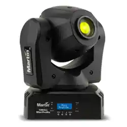
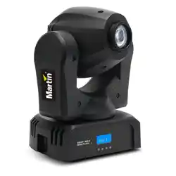
Introduction
The RUSH™ MH 8 Mini Profile is a fast, compact moving head profile fixture
with an 18 W long-life LED engine. It provides an 8-position plus open gobo
wheel, an 8-position plus open color wheel, smooth electronic dimming, strobe
effects, and a manually adjustable focus lens. The rugged, lightweight
construction makes it ideal for mobile DJs, touring, and small venues.
The fixture is supplied with this user manual, a 1.9 m (6 ft.) power cable ready
for a local power plug (not included), a second power cable fitted with a US
power plug, and a mounting bracket for attachment of a suitable, user-supplied
rigging clamp.
Before using the product for the first time
1. Read ‘Safety information’ starting on page 4 before installing, operating or
servicing the fixture.
2. Unpack and ensure that there is no transportation damage before using
the fixture. Do not attempt to operate a damaged fixture.
3. (Outside U.S.A.) If the fixture is not going to be hard-wired to a mains
supply, install a local power plug (not supplied) to the end of the supplied
power cable.
4. Before operating, ensure that the voltage and frequency of the power
supply match the power requirements of the fixture.
5. Check the support pages on the Martin Professional website at
www.martin.com for the most recent user documentation and technical
information about the fixture. Martin™ user manual revisions are identified
by the revision letter at the bottom of the inside cover.
Note that whenever AC power is applied to the fixture, it will reset all effects
and functions to their home positions. Be prepared for the fixture head to
move. A reset usually takes around 20 seconds.
RUSH™ MH 8 Mini Profile User Manual 9
Physical installation
Warning! Read ‘Safety information’ on page 4 before
installing the fixture.
The fixture is designed for indoor use only and must be used in
a dry location with adequate ventilation. Ensure that none of the
fixture’s ventilation slots are blocked and all minimum distances
are observed.
The fixture must be installed by a qualified technician. It must be
oriented vertically, either upright on the floor or other horizontal
surface, or suspended upside-down from a suitable structure.
Fasten the fixture to a secure structure or surface. Do not stand
it on a surface or leave it where it can be moved or fall over. If
you install the fixture in a location where it may cause injury or
damage if it falls, secure it as directed in this user manual using
a securely anchored safety cable that will hold the fixture if the
primary fastening method fails.
Martin™ can supply safety cables and rigging clamps that are suitable for use
with the fixture (see ‘Accessories’ on page 32).
Fastening the fixture to a flat surface
The fixture can be fastened to a hard, fixed, flat surface. Ensure that the
surface and all fasteners used can support at least 10 times the weight of all
fixtures and equipment they will support.
Fasten the fixture securely. Do not stand it on a surface or leave it where it can
be moved or fall over. If you install the fixture in a location where it may cause
injury or damage if it falls, secure it as directed below with a securely anchored
safety cable that will hold the fixture if the primary fastening method fails.
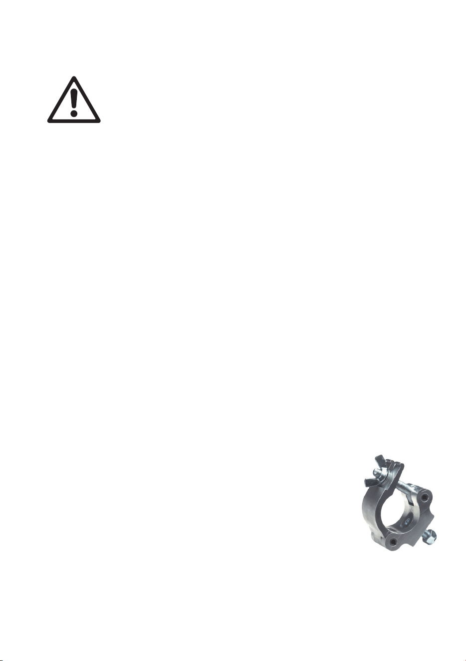
Mounting the fixture on a truss
The fixture can be clamped to a truss or similar rigging
structure. It must be suspended vertically, hanging
downwards only. Use a suitable rigging clamp such as a G-
clamp or a half-coupler clamp (see illustration on right)
fastened to the included clamp attachment bracket.
To clamp the fixture to a truss:
1. Check that the rigging structure can support at least 10 times the weight of
all fixtures and equipment to be installed on it.
2. Block access under the work area.
10 RUSH™ MH 8 Mini Profile User Manual
A
B
B
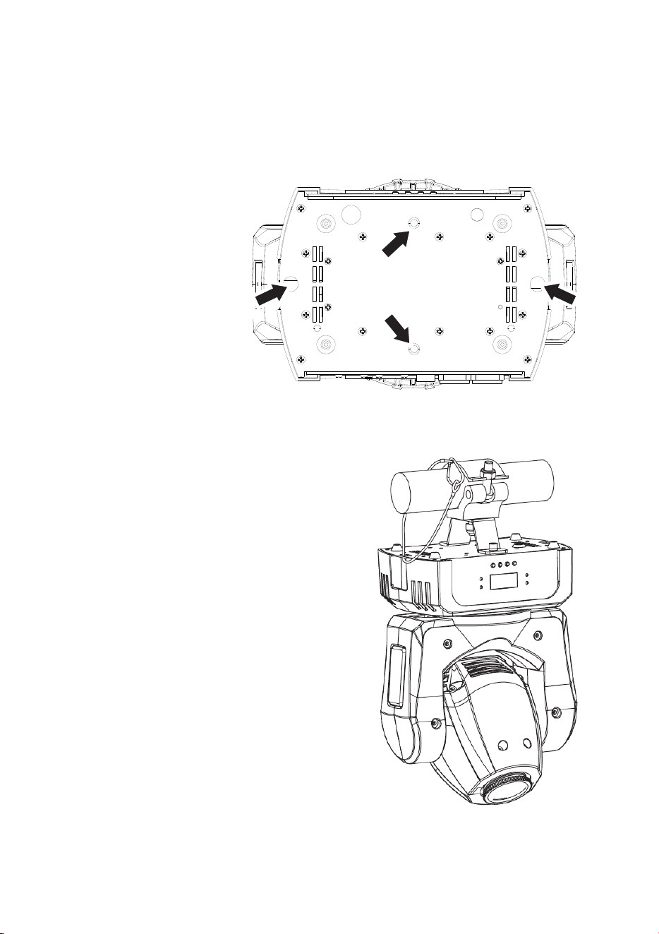
3. Bolt a rigging clamp securely to the supplied clamp-attachment bracket.
The bolt used must be M12, grade 8.8 steel minimum, and fastened with a
self-locking nut.
4. Fasten the bracket to the fixture by screwing the two hex socket (Allen)
bolts provided fully into holes A in the base of the fixture (see illustrations
on right and below) using the washers provided or suitable lock washers.
5. Working from a stable
platform, hang the fixture
vertically on the truss
and fasten the rigging
clamp onto the truss.
6. Secure the fixture
with a safety cable
as directed below.
7. Check that the head
will not collide with other
fixtures or objects.
Securing with a safety cable
Secure the fixture with a safety cable (or
other secondary attachment) that is
approved for the weight of the fixture so
that the safety cable will hold the fixture if
the primary attachment fails. Loop the
safety cable through one of the two
attachment points B in the base of the
fixture base (see illustrations above and to
right) and around a secure anchoring
point.
If a safety cable attachment point becomes
damaged or deformed, do not use the
fixture. Return it to Martin™ for repair.
RUSH™ MH 8 Mini Profile User Manual 11
AC power
Warning! Read ‘Safety information’ on page 4 before
connecting the fixture to AC mains power.
For protection from electric shock, the fixture must be grounded
(earthed). The power distribution circuit must be equipped with a
fuse or circuit breaker and ground-fault (earth-fault) protection.
Socket outlets or external power switches used to supply the
fixture with power must be located near the fixture and easily
accessible so that the fixtures can easily be disconnected from
power.
Do not use an external dimming system to supply power to the fixture, as this
may cause damage to the fixture that is not covered by the product warranty.
The fixture can be hard-wired to a building electrical installation if you want to
install it permanently, or a power plug (not supplied) that is suitable for the
local power outlets can be installed on the power cable. Socket outlets or
external power switches used to supply the fixture with power must be located
near the fixture and easily accessible so that the fixture can easily be
disconnected from power.
If you install a power plug on the power cable, install a grounding type
(earthed) plug with integral cable grip that is rated minimum 250 V, 6 A. Follow
the plug manufacturer’s instructions and connect the wires in the power cable
as shown in this table:
Live or L Neutral or N
Earth, Ground or
US system
Black White Green
EU system
Brown Blue Yellow/green
The fixture has an auto-ranging power supply that accepts AC mains power at
100-240 V at 50/60 Hz. Do not apply AC mains power at any other voltage or
frequency to the fixture.
12 RUSH™ MH 8 Mini Profile User Manual
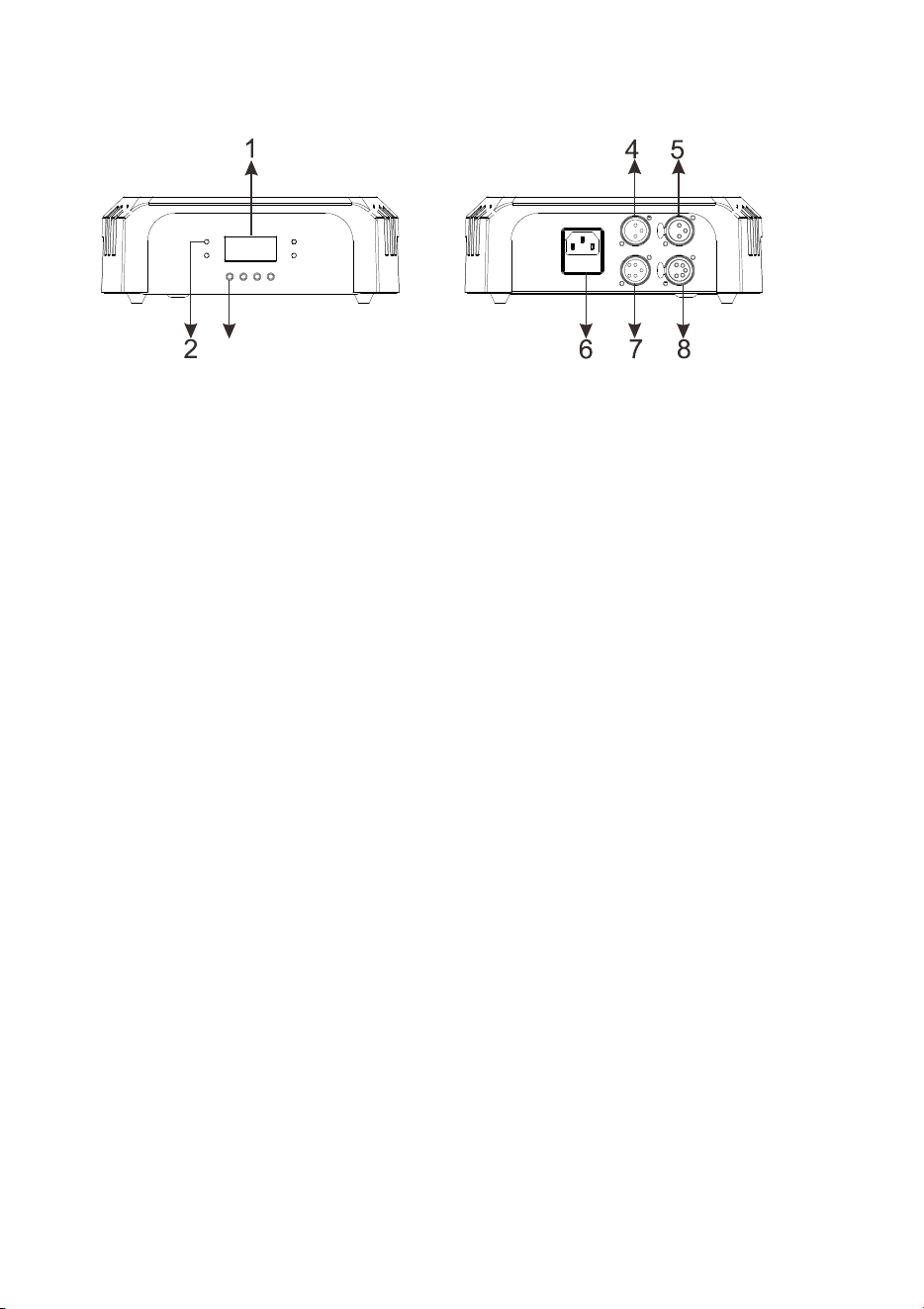
Fixture overview
3
1 – Display
2 – LEDs
Four LEDs provide status information.
• DMX: Valid DMX signal present.
• CLIENT: Fixture operating as a stand-alone client.
• MASTER: Fixture operating as the stand-alone master.
• SOUND: Audio signal triggering stand-alone sequence.
3 – Control buttons
• MENU: Pres
s to activate the menu. Within the menu, press to escape and
return to the previous lev
el. Press and hold to exit the menu.
• DOWN: Press to scroll down through menu options.
• UP: Press to scroll up through menu options.
• ENTER: Press to confirm and save the menu selection.
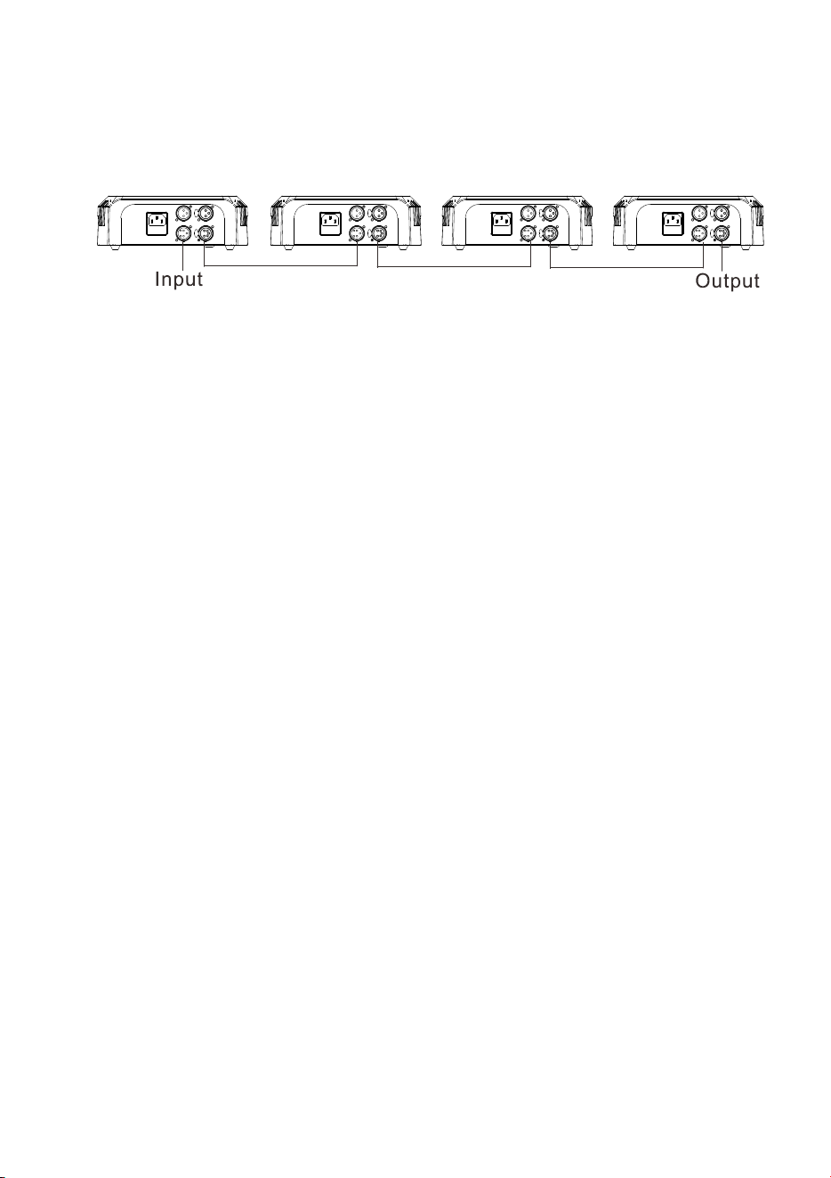
4, 5 – 3-pin XLR DMX input/output
For your convenience, 3 and 5-pin XLR sockets are provided for DMX input
and output (throughput).
6 – AC mains power socket and primary fuse holder
The IEC mains power input socket includes the holder for the T 2.0 A primary
fuse. A spare fuse is located behind the fuse holder.
7, 8 – 5-pin DMX input/output
RUSH™ MH 8 Mini Profile User Manual 13
Control data link
A DMX 512 data link is required in order to control the fixture via DMX. The
fixture has 3-pin and 5-pin XLR connectors for DMX data input and output.
Up to 32 devices can be linked together on a single daisy chain. The total
number of fixtures in one 512-channel DMX universe is limited by the number
of DMX channels required by the fixtures. Note that if independent control of a
fixture is required, it must have its own DMX channels. Fixtures that are
required to behave identically can share the same DMX address and
channels. To add more fixtures or groups of fixtures when the above limits are
reached, add a DMX universe and/or split the daisy-chained link into branches.
Tips for reliable data transmission
Use shielded twisted-pair cable designed for RS-485 devices: standard
microphone cable cannot transmit control data reliably over long runs. 24
AWG cable is suitable for runs up to 300 meters (1000 ft.). Heavier gauge
cable and/or an amplifier is recommended for longer runs. The pin-out on all
connectors is pin 1 = shield, pin 2 = cold (-), and pin 3 = hot (+). Pins 4 and 5
in the 5-pin XLR connectors are not used in the fixture but are available for
possible additional data signals as required by the DMX512-A standard.
Standard pin-out is pin 4 = data 2 cold (-) and pin 5 = data 2 hot (+).
To split the link into branches, use an opto-isolated splitter such as the
Martin™ DMX 5.3 Splitter. Terminate the link by installing a termination plug in
the output socket of the last fixture. The termination plug, which is a male XLR
plug with a 120 Ohm, 0.25 W resistor soldered between pins 2 and 3, “soaks
up” the control signal so it does not reflect and cause interference. If a splitter
is used, terminate each branch of the link.
Connecting the data link
To connect the fixture to data:
1. Connect the DMX data output from the controller to the closest fixture’s
male XLR DMX input connector.
2. Connect the first fixture’s DMX output to the DMX input of the next fixture
and continue connecting fixtures output to input. Terminate the last fixture
on the link with a DMX termination plug.

14 RUSH™ MH 8 Mini Profile User Manual
Fixture setup
This section explains the fixture characteristics that can be set that determine
how it can be controlled and will behave. These settings are made using the
menus available from the control panel, and are retained, even when the
fixture is powered off.
Only the most commonly used menu options for fixture setup are described in
this section. A complete map of the control menu structure and brief
explanations of their purposes can be found on page 24.
Using the control menus
To access the control menus, press the MENU button. Navigate the menu
structure using the ENTER, DOWN and UP buttons. To select a menu option
or to confirm a selection, press the ENTER button. To return to a higher level
in the menu structure without making a change, press the MENU button.
To exit the control menus completely, press and hold the MENU button.
DMX addressing
The DMX address, also known as the start channel, is the first channel used to
receive instructions from a DMX controller. The fixture is controlled using ten
(10) DMX channels. Each DMX controlled fixture must have a DMX address
set. For example, if a fixture has a DMX address of 10, then it uses channels
10, 11, 12, 13, 14, 15, 16, 17, 18, and 19. The following fixture in the DMX
chain could then be set to a DMX address of 20.
For independent control, each fixture must be assigned its own control
channels. Two fixtures of the same type may share the same address if
identical behavior is desired. Address sharing can be useful for diagnostic
purposes and symmetric control, particularly when combined with the inverse
pan and tilt options.
To set the fixture’s DMX address:
1. In the control menu, select DMX ADDRESS and press ENTER to confirm.
The present address will blink in the display.
2. Use the UP and DOWN buttons to select an address from 1 to 503.
3. Press ENTER to confirm your selection.
Behavior without DMX (DMX State)
The DMX STATE setting determines how the fixture behaves when it is not
receiving a DMX signal. You can set the fixture to enter Show Mode, black out,
or hold the effect it was displaying when the DMX signal stopped. The fixture is
set to BLACKOUT by default.

RUSH™ MH 8 Mini Profile User Manual 15
To adjust the setting:
1. Select DMX STATE and press ENTER. The currently set option will blink in
the display.
2. Use the DOWN and UP buttons to select SHOW MODE (fixture enters
Show Mode), BLACKOUT (fixture blacks out) or HOLD (fixture shows the
last effect it was displaying before the DMX signal stopped).
3. Press ENTER to save your selection.
Stand-alone settings
The fixture will operate in stand-alone mode if it is not receiving a DMX signal
and the DMX STATE menu option is set to SHOW MODE (see above), or if
you enter the SHOW MODE menu in the control panel.
Stand-alone show selection (Show Mode)
Four pre-programmed stand-alone shows are available. To set the show that
the fixture will run in Show Mode:
1. Select SHOW MODE and press ENTER to confirm. The currently selected
show will blink in the display.
2. Use the DOWN and UP buttons to select Show 1, 2, 3 or 4.
3. Press ENTER to save your selection.
Master/client operation
Fixtures in Show Mode can be linked in a c
hain and set to master/client
operation, where one master fixture running a standalone show controls
the behavior of client fixtures. Two client modes are available:
• Fixtures in Client 1 mode copy the master.
• Fixtures in Client 2 mode are synchronized with the master but have slight
variations in behavior.
You must set all the fixtures except one as clients. If you set more than
one fixture in the chain to act as master, you may cause damage that is
not covered by the product warranty.
To operate fixtures in master/client mode:
1. Link fixtures in a chain, using DMX cable to connect one fixture’s DMX
OUT socket to the next fixture’s DMX IN
socket. See ‘Control data link’ on
page 13.
2. In the MASTER CLIENT menu, set one fixture to MASTER and set all the
other fixtures to CLIENT 1 or CLIENT 2.
3. Set the master fixture in the chain to run one of its four standalone shows
using its SHOW MODE menu (see ‘Show Mode’ above).

16 RUSH™ MH 8 Mini Profile User Manual
4. Set all the fixtures in the chain to DMX STATE SHOW MODE.
5. Make sure that the fixtures are not receiving a DMX signal.
Sound activation in show mode
Show Mode can be combined with sound activation. The fixture has a built-in
microphone that can be used to trigger scene changes in sync with a music
beat (music trig) when the fixture is running in Show Mode.
To enable sound activation:
1. Select SOUND MODE and press ENTER.
2. Use the DOWN and UP buttons to select ON (sound activation enabled) or
OFF (sound activation disabled).
3. Press ENTER to save your selection.
To adjust the sensitivity of sound activation to the volume of the music:
1. Turn on the music source and set it to the desired volume.
2. Select SOUND SENSE and press ENTER.
3. Use the DOWN and UP buttons to change the sensitivity level from 0
to100.
4. When the fixture responds correctly to the beat, press ENTER to save
your selection.
Pan/tilt inversion
The PAN INVERSE and TILT INVERSE menus can be used to reverse the
direction of pan and tilt. These settings are useful for symmetrical effects with
multiple fixtures, or when coordinating the movement of fixtures that are floor
mounted and rigged upside down.
To adjust the pan inversion settings:
1. Select PAN INVERSE and press ENTER to confirm. The currently set
mode will blink in the display.
2. Use the DOWN and UP buttons to select YES (tilt inversion) or NO
(normal) mode.
3. Press ENTER to save your selection.
To adjust the tilt inversion settings:
1. Select TILT INVERSE and press ENTER to confirm. The currently set
mode will blink in the display.
2. Use the DOWN and UP buttons to select YES (tilt inversion) or NO
(normal) mode.
3. Press ENTER to save your selection.
RUSH™ MH 8 Mini Profile User Manual 17
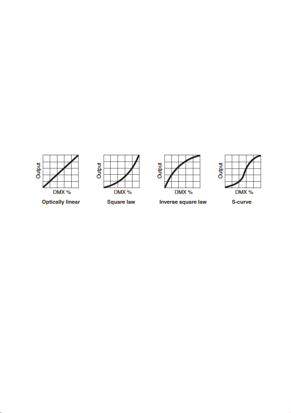
Dimmer settings
Dimming curve
Four dimming curves are available to modify dimmer response. The default is
MODE 2. The settings affect response as follows:
MODE 1 LINEAR: the increase in light intensity appears to be linear as
DMX value is increased.
MODE 2 SQUARE LAW: light intensity control is finer at low levels and
coarser at high levels.
MODE 3 INVERSE SQUARE LAW: light intensity control is coarser at low
levels and finer at high levels.
MODE 4 S-CURVE: light intensity control is finer at low levels and high
levels and coarser at medium levels.
To set the fixture’s dimmer curve:
1. Select DIMMER CURVE and press ENTER to confirm. The mode that is
currently active will blink in the display.
2. Use the DOWN and UP buttons to select the desired mode.
3. Press ENTER to save your selection.
Dimmer speed
There are two dimmer speed options:
• SNAP is the default setting. It sets the dimmer to exactly follow changes in
dimming level sent from the controller. This gives the fastest dimmer
response.
• FADE adds an approximate two-second smooth fade to changes in
dimming level sent from the controller. This gives the smoothest dimmer
fading.
To set the dimmer speed:
1. Select DIMMER SPEED and press ENTER to confirm.
2. Use the DOWN and UP buttons to select SNAP or FADE. Press ENTER
to confirm.

18 RUSH™ MH 8 Mini Profile User Manual
Dimmer calibrate
The dimmer calibration function allows you to decrease output to achieve
uniform dimming with other fixtures. (If a fixture’s output appears to be low,
verify that the DIMMER CALIBRATE level is 100.)
To calibrate dimming on a fixture on which the light output is too high:
1. Select DIMMER CALIBRATE and press ENTER to confirm.
2. Use the DOWN and UP buttons to adjust light output to a level between 50
and 100. The default level is 100 (full intensity).
3. Press ENTER to confirm.
Backlight
To turn the control panel display backlight on or off:
1. Select BACK LIGHT and press ENTER to confirm. The present mode will
blink in the display.
2. Use the DOWN and UP buttons to select ON or OFF.
3. Press ENTER to save your selection.
Fixture time
To display the fixture’s operating hours counter, select FIXTURE TIME and
press ENTER. The display will show the number of hours the fixture has been
in operation since manufacture. Press MENU to exit.
Reset
The fixture resets each time you power it on, but you can also reset the fixture
manually from the control panel and by DMX. To carry out a manual reset,
scroll to RESET and press ENTER to reset the fixture, or press MENU to exit
without resetting. A reset takes approx. 20 seconds. After this, the fixture
returns to its state before the reset.
Fan mode
Fan speed can be adjusted to maximize light output or quiet operation.
1. Select FAN MODE and press ENTER.
2. Using the DOWN and UP buttons, toggle between the two modes:
- LOW. Fans run at constant low speed for quieter operation. Light
output is reduced when necessary to control fixture temperature.
- AUTO. Fan speed increases when necessary to control fixture
temperature, but light output is constant.
3. Press ENTER to confirm your choice.

RUSH™ MH 8 Mini Profile User Manual 19
Home position adjustment (offsets menu)
If the fixture head, gobo wheel, or color wheel does not return to its home
position, even after a reset, you can adjust the home position by defining
offsets.
To make the adjustment from the control panel:
1. Reset the fixture as described above.
2. Press and hold ENTER for at least 3 seconds to enter Offset mode.
3. Use the DOWN and UP buttons up to choose a function to adjust: PAN,
TILT, GOBO, or COLOR. Press ENTER
4. Use the DOWN and UP buttons to adjust the effect’s home or open
position.
5. Press ENTER to save your selection (or press MENU to exit without
saving any changes).

20 RUSH™ MH 8 Mini Profile User Manual
Effects
See ‘DMX protocol’ on page 24 for a full list of the DMX channels and values
required to control the different effects.
Pan and tilt
The fixture’s head can be panned through 540° and tilted through 230° with
16-bit coarse and fine control. Using the control menus it is possible to invert
pan or tilt movement.
Light output can be blacked out when the head moves with the “Auto-blackout
= ON” command (DMX level 145 to149) on channel 10. To turn this feature off,
use the “Auto-blackout = OFF” command. Pan and tilt speed can also be set to
slow, medium, or fast using commands on channel 10.
The pan and tilt home position, as well as the open gobo position, can be
adjusted from the controller. To make adjustments via DMX:
1. Select the fixture on the controller.
2. Enable calibration (DMX value 55-59) on the fixture’s DMX channel 10,
Fixture Control Settings.
3. Adjust the effect’s position using its DMX channel.
4. Store the effect’s calibration value on DMX channel 10. Store both pan and
tilt calibration with DMX value 165-169, gobo wheel calibration with DMX
value 210-214, pan calibration only with DMX value 235-249, or tilt
calibration only with DMX value 240-244.
5. When finished calibrating effects, set channel 10 to “No function” to
resume normal DMX control.
Strobe effects
The fixture electronically provides instant open and blackout, variable speed
flash from 3 to 20 flashes per second, random strobe effects, and pulsing
effects.
Electronic dimming
Overall intensity can be precisely adjusted from 0 to 100% using 16-bit coarse
and fine electronic dimming.
Four different dimming curves are available (see ‘Dimmer settingson page 17).
The dimming curve can be selected from the control menu or by DMX
commands on channel 10.
RUSH™ MH 8 Mini Profile User Manual 21
Colors
The color wheel provides eight colors plus an open white position. See the
DMX protocol for details. Colors can be individually selected or scrolled to give
split colors. The wheel can be rotated at varying speeds, both clockwise and
counter-clockwise, or set to display random colors at slow, medium and fast
speeds.
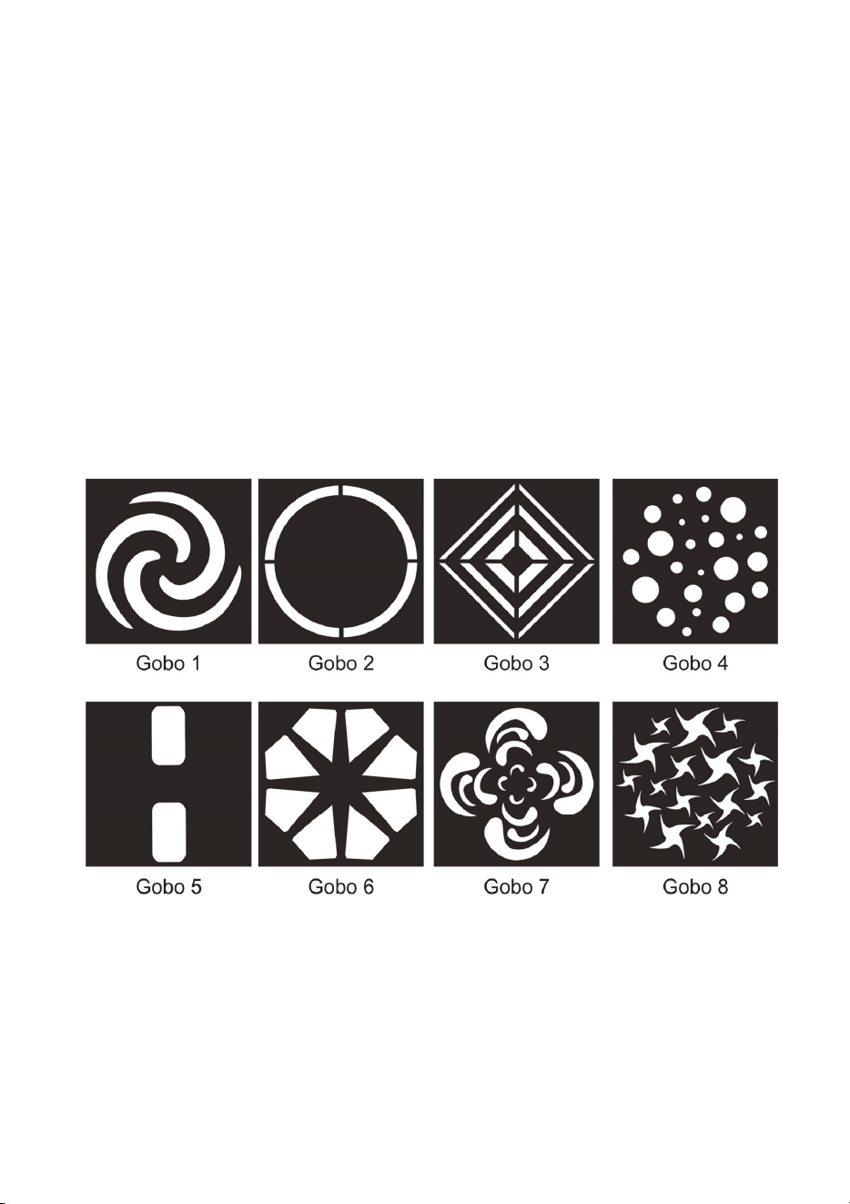
Gobos
The gobo wheel provides eight gobo patterns, shown below, plus an open
white position. Gobos can be stepped, or continuously scrolled to give split
gobo patterns. The wheel can be rotated at varying speeds, both clockwise
and counter-clockwise, or set to display random gobos at slow, medium and
fast speeds.
Adjust the focus lens manually to project the sharpest image.
To avoid passing the open white position when changing colors and gobos,
use the “Parameter shortcuts = OFF” command on channel 10. For faster
color and gobo changes, use Parameter shortcuts = ON”.

22 RUSH™ MH 8 Mini Profile User Manual
Maintenance
Warning! Read ‘Safety information’ on page 4 before
servicing the fixture.
There are no user serviceable parts inside the fixture. Do not
open the housing. Refer any service operation not described in
this user manual to a qualified service technician.
Disconnect the fixture from mains power before cleaning or
servicing.
Service fixtures in an area where there is no risk of injury from
failing parts, tools or other materials.
The user may carry out the service operations described in this manual. All
other service operations must be carried out by an authorized Martin™ service
technician. Do not try to repair the fixture yourself, as you may create a safety
risk or cause damage that is not covered by the product warranty.
Installation, on-site service and maintenance can be provided worldwide by the
Martin Professional™ Global Service organization and its approved agents,
giving owners access to Martin’s expertise and product knowledge in a
partnership that will ensure the highest level of performance throughout the
product’s lifetime. Please contact Martin™ for details.
Cleaning
Excessive dust, smoke fluid, and particle buildup degrades performance,
causes overheating and will damage the fixture. Damage caused by
inadequate cleaning or maintenance is not covered by the product warranty.
The cleaning of external optical lenses must be carried out periodically to
optimize light output. Cleaning schedules for lighting fixtures vary greatly
depending on the operating environment. It is therefore impossible to specify
precise cleaning intervals for the fixture. Environmental factors that may result
in a need for frequent cleaning include:
• Use of smoke or fog machines.
• High airflow rates (near air conditioning vents, for example).
• Presence of cigarette smoke.
• Airborne dust (from stage effects, building structures and fittings or the
natural environment at outdoor events, for example).
If one or more of these factors is present, inspect fixtures within their first 100
hours of operation to see whether cleaning is necessary. Check again at
frequent intervals. This procedure will allow you to assess cleaning
requirements in your particular situation. If in doubt, consult your Martin dealer
about a suitable maintenance schedule.
RUSH™ MH 8 Mini Profile User Manual 23
Use gentle pressure only when cleaning, and work in a clean, well-lit area. Do
not use any product that contains solvents or abrasives, as these can cause
surface damage.
To clean the fixture:
1. Disconnect the fixture from power and allow it to cool for at least 10
minutes.
2. Vacuum or gently blow away dust and loose particles from the outside of
the fixture and the air vents at the back and sides of the head and in the
base with low-pressure compressed air.
3. Clean surfaces by wiping gently with a soft, clean lint-free cloth moistened
with a weak detergent solution. Do not rub glass surfaces hard: lift
particles off with a soft repeated press. Dry with a soft, clean, lint-free cloth
or low-pressure compressed air. Remove stuck particles with an
unscented tissue or cotton swab moistened with glass cleaner or distilled
water.
4. Check that the fixture is dry before reapplying power.
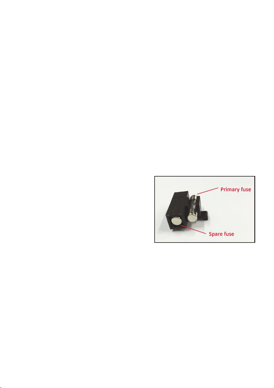
Replacing the primary fuse
If the fixture is completely dead, the
fixture’s primary fuse F1 may have blown
and it may be necessary to install a new
fuse. This fuse is located in the fuse
holder below the mains input socket
along with a spare. Replace with a fuse
of the same size and specified rating
only.
If you need to replace the fuse:
1. Disconnect the fixture from power and allow it to cool.
2. Remove the fuse holder and replace the spent fuse with the spare fuse.
3. Close the fuse holder before reapplying power.
Service and repairs
Never try to repair the fixture by yourself as this may result in damage or
malfunction and it may potentially void your product warranty. The equipment
must only be serviced or repaired by an authorized Martin service technician.
24 RUSH™ MH 8 Mini Profile User Manual
DMX protocol
Channel Value Function
1 0-255 Dimmer Coarse: 0-100%
2 0-255 Dimmer Fine
3
0-7
8-15
16-131
132-167
168-203
204-239
240-247
248-255
Strobe
Off
Open
Strobe, slow to fast
Fast close, slow open
Fast open, slow close
Pulse open and close
Random strobe
Open
4
0
1-14
15
16-29
30
31-44
45
46-59
60
61-74
75
76-89
90
91-104
105
106-119
120
121-134
135-160
161-163
164-166
167-169
170-172
173-175
176-178
179-181
182-184
185-192
193-214
215-221
222-243
Color Wheel
Open
Open → Red
Red
Red → Orange
Orange
Orange → Yellow
Yellow
Yellow → Light Green
Light Green
Light Green → Dark Blue
Dark Blue
Dark Blue → Magenta
Magenta
Magenta → Light Blue
Light Blue
Light Blue → Pink
Pink
Pink → Open
Open
Stepped Scroll
Red
Orange
Yellow
Light Green
Dark Blue
Magenta
Light Blue
Pink
Open
Continuous Rotation
CW, Fast → Slow
Stop
CCW, Slow → Fast
RUSH™ MH 8 Mini Profile User Manual 25
Channel Value Function
4
cont.
244-247
248-281
252-255
Random Colors
Fast
Medium
Slow
5
0
1-14
15
16-29
30
31-44
45
46-59
60
61-74
75
76-89
90
91-104
105
106-119
120
121-134
135-160
161-163
164-166
167-169
170-172
173-175
176-178
179-181
182-184
185-192
193-214
215-221
222-243
244-247
248-251
252-255
Gobo Wheel
Open
Open → Gobo 1
Gobo 1
Gobo 1 → Gobo 2
Gobo 2
Gobo 2 → Gobo 3
Gobo 3
Gobo 3 → Gobo 4
Gobo 4
Gobo 4 → Gobo 5
Gobo 5
Gobo 5 → Gobo 6
Gobo 6
Gobo 6 → Gobo 7
Gobo 7
Gobo 7 → Gobo 8
Gobo 8
Gobo 8 →Open
Open
Stepped Scroll
Gobo 1
Gobo 2
Gobo 3
Gobo 4
Gobo 5
Gobo 6
Gobo 7
Gobo 8
Open
Continuous Rotation
CW, Fast → Slow
Stop
CCW, Slow → Fast
Random Gobos
Fast
Medium
Slow
6 0-255
Pan: 0°→ 540°
7 0-255
Pan (fine)
8 0-255
Tilt: 0°→ 230°
9 0-255
Tilt (fine)

26 RUSH™ MH 8 Mini Profile User Manual
10
0-9
10-14
15-19
20-24
25-29
30-34
35-54
55-59
60-64
65-69
70-74
75-79
80-84
85-89
90-94
95-99
100-104
105-144
145-149
150-154
155-159
160-164
165-169
170-209
210-214
215-234
235-239
240-244
245-249
250-255
Fixture Control Settings
No function (disables calibration)
Reset fixture
No function
Reset color
No function
Reset pan and tilt
No function
Enable calibration
Linear dimmer curve
Square law dimmer curve (default)
Inverse square law dimmer curve
S-curve dimmer curve
Pan and tilt speed = Normal
Pan and tilt speed = Fast (default)
Pan and tilt speed = Slow
Parameter shortcuts = ON (default)
Parameter shortcuts = OFF
No function
Auto-blackout = On
Auto-blackout = Off (default)
Illuminate display
Turn off display
Store pan & tilt calibration
No function
Store gobo wheel calibration
No function
Store pan calibration
Store tilt calibration
Reset all calibrations to factory default
No function

RUSH™ MH 8 Mini Profile User Manual 27
Control menus
To access the control menus, press the MENU button. Use the UP and DOWN
buttons to navigate the menus. Select a menu option with the ENTER button.
For more information, see ‘Using the control menus’ on page 14.
Default fixture settings are shown in bold.
Menu Sub-menu Explanation
DMX Address 1–512
Fixture DMX address
setting
Show Mode Show 1…Show 4
Select stand-alone
program
Master Client
Master Fixture acts as master
Client 1
Client copies master
Client 2 Client s
ynced by master
Sound Mode
On
Toggle music trigger for
stand-alone operation
Off
Sound Sense 0…100 (default 90)
Microphone sensitivity for
music trigger
DMX State
Show Mode
Fixture behavior if DMX
control signal is missing or
lost
Blackout
Hold
Dimmer Curve
Mode 1 Optically linear
Mode 2
Square law
Mode 3 Inverse square law
Mode 4 S-curve
Dimmer Speed
Fade
Smoother dimming
Snap Faster dimming
Dimmer Calibrate 50-100 Adjust max. output
Back light
On
Toggle display panel
backlight
Off
Pan Inverse
Yes Invert pan control
No
Normal pan control
Tilt Inverse
Yes Invert tilt control
No
Normal tilt control
Auto test Run test routine
28 RUSH™ MH 8 Mini Profile User Manual
Menu Sub-menu Explanation
Manual Test
Pan
Manual control of all effects
Tilt
Color
Gobo
Shutter
Dimmer
LED Temp. Temperature readout
Fan Mode
Auto
Optimize cooling for light
output intensity
Low
Optimize cooling for
quietness (output intensity
is reduced if necessary to
limit temperature)
Firmware Version
Currently installed firmware
version
Fixture Time
Fixture operating hours
counter
PRO Defaults
Yes
Restore factory default
settings
No
Exit
Reset
Yes
Force a fixture reset
No
To access the Offset menu, press MENU to enter the menu structure and then
press and hold ENTER for three seconds.
Menu Sub-menu Setting Explanation
Offset Menu
Pan -127127 Pan offset
Tilt -127127 Tilt offset
Gobo -127127 Gobo offset
Color -127127 Color offset

RUSH™ MH 8 Mini Profile User Manual 29
Troubleshooting
This section describes a few common problems that may occur during
operation and provides some suggestions for easy troubleshooting:
Symptom Potential Causes Remedies
No light from fixture,
or fans not working.
Power supply issue
such as blown fuse,
faulty connector or
damaged cable.
Ensure that the mains
supply is connected and
supplying power to the
fixture.
Check all power
connections and cables.
Check and if necessary
replace the fixture fuse.
One of the control
channels is
unresponsive or only
responds
intermittently.
DMX setup or DMX link
fault.
Damaged step motor or
cable connection
between head and body.
See next section.
Contact your Martin
authorized distributor or
service center for
assistance.
Fixture does not
respond to DMX
control.
Fault in the DMX
network due to
connector or cable
damage, incorrect DMX
addressing, or potential
interference from
proximity to a high
voltage installation.
Ensure that fixture’s DMX
address matches address
set on DMX control device.
Check that fixture DMX
LED is on, and if not, check
all DMX cables and
connections.
Ensure that DMX link is
terminated.
Check that all components
on DMX link use standard
DMX polarity.
Attempt to control the
fixture with another DMX
control device.
Move or shield link if it is
close to an unshielded
high-voltage installation.
30 RUSH™ MH 8 Mini Profile User Manual
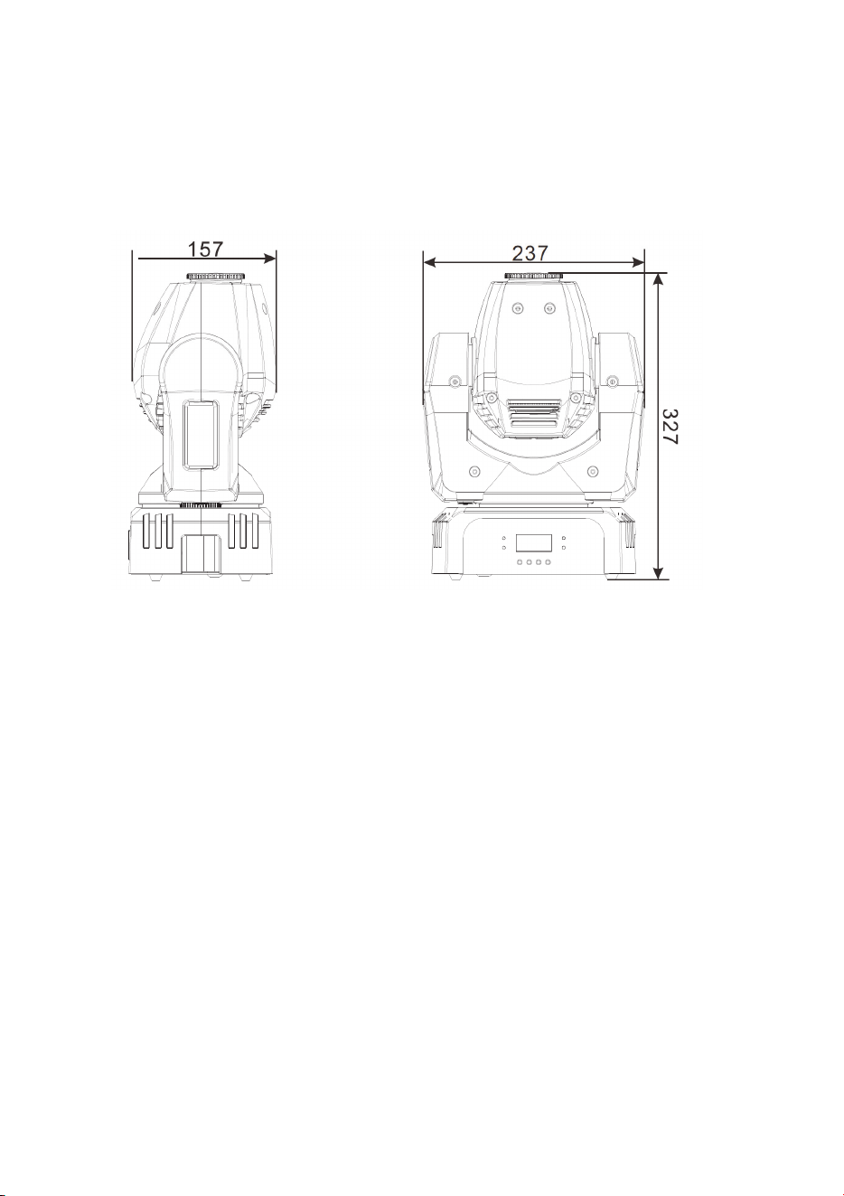
Specifications
Physical
Dimensions (LxWxH) ....................... 157 x 237 x 327 mm (6.1 x 9.3 x 12.9 in.)
Weight ...................................................................................... 4.5 kg (9.9 lbs.)
Dynamic Effects
Color wheel .......................... 8 colors plus open, variable and random rotation
Gobo wheel ............... 8 static gobos plus open, variable and random rotation
Strobe ..................... Variable from 3 - 20 Hz, pulse effects and random strobe
Electronic dimming ................................ 0 - 100%, four dimming curve options
Pan ............................................................................................................ 540°
Tilt .............................................................................................................. 230°
Optics
Light source ................................................ 18 W OSRAM LE UW Q8WP LED
Minimum LED lifetime ..................... 50 000 hours (to >70% luminous output)*
Beam angle ................................................................................................. 14°
Focus ..................................................................................................... Manual
*Figure obtained under manufacturer´s test conditions
Control and Programming
Control options ................................ DMX, 4 s
tand-alone shows, master/client
DMX channels ............................................................................................... 10
Stand-alone trigger ......................................................................... Auto, music
DMX compliance ............................................................ USITT DMX512/1990
Interface ................................................ Control panel with backlit LCD display

RUSH™ MH 8 Mini Profile User Manual 31
Construction
Color ......................................................................................................... Black
Housing .......................................... High impact flame retardant thermoplastic
IP rating ................................................................................................... IP 20
Installation
Mounting points ......................................................... Bracket for rigging clamp
Location ................ Dry location only, must be fastened to surface or structure
Orientation .................................................. Vertical (head down if suspended)
Minimum distance to illuminated surfaces ................................ 200 mm (8 in.)
Minimum distance to combustible materials ............................. 100 mm (4 in.)
Minimum clearance around fans and vents .............................. 100 mm (4 in.)
Connections
AC power input ............................................................................................ IEC
DMX data in/out ........................................................ 3-pin & 5-pin locking XLR
Electrical
AC power ............................................................ 100-240 V nominal, 50/60 Hz
Power supply unit ................................... Auto-ranging electronic switch mode
Fuse ...................................................................................................... T 2.0 A
Typical power and current
120 V, 60 Hz ................................................................................... 52 W, 0.8 A
230 V, 50 Hz ................................................................................... 50 W, 0.5 A
Typical half-cycle RMS inrush current...................................................... 6.4 A
Measurements made at nominal voltage with all LEDs at full intensity. Allow
for a deviation of +/- 10%.
Thermal
Cooling ...................................................... Forced air (temperature-regulated)
Maximum ambient temperature (T
a
max.) ................................. 40° C (104° F)
Minimum ambient temperature (T
a
min) .......................................... 0°C (32° F)
Total heat dissipation* ................................................................... 180 BTU/hr.
*Calculated, +/- 10%, at full intensity, full white
Approvals
EU safety ....................... EN 60598-2-17 (EN 60598-1), EN 62471, EN 62493
EU EMC .................. EN 55015; EN 55032; EN 55103-1,-2; EN 61000-3-2,-3;
EN 61000-4-2, -4, -5; EN 61547
US safety ............................................................................................. UL 1573
US EMC ............................................................. CFR Title 47 Part 15 Class A
Canadian safety ................................................................ CSA C22.2 No. 166
32 RUSH™ MH 8 Mini Profile User Manual
Canadian EMC .................................................................... ICES-003 Class A
Australia/NZ (pending) ............................................................................. RCM
Included Items
Power cable, 1.9 m without mains plug
Power cable, 1.9 m with US plug
Bracket for rigging clamp attachment
Accessories
Installation hardware
Half-coupler clamp .................................................................... P/N 91602005
G-clamp ..................................................................................... P/N 91602003
Quick-trigger clamp ................................................................... P/N 91602007
Safety cable, safe working load 50 kg ....................................... P/N 91604003
Related Items
RUSH™ Software Uploader 1 ................................................... P/N 91611399
Ordering Information
RUSH™ MH 8 Mini Profile in cardboard box ............................ P/N 90280110
Specifications subject to change without notice. For latest product
specifications, see www.martin.com
Disposing of this product
RUSH by Martin™ products are supplied in compliance with
Directive 2012/19/EC of the European Parliament and of the
Council of the European Union on WEEE (Waste Electrical and
Electronic Equipment), where applicable. Help preserve the
environment! Ensure that this product is recycled at the end of its
life. Your supplier can give details of local arrangements for the
disposal of RUSH by Martin products

RUSH™ MH 8 Mini Profile User Manual 33
Photobiological Safety Warning
The label shown below is displayed on this product. If it becomes difficult or
impossible to read, it must be replaced using the illustration below to
reproduce a new label sized 45 x 18 mm, in black on a yellow background.
RISK GROUP 2
CAUTION. Possibly hazardous optical
radiation emitted from this product.
Do not stare at operating lamp. May be
harmful to the eyes.