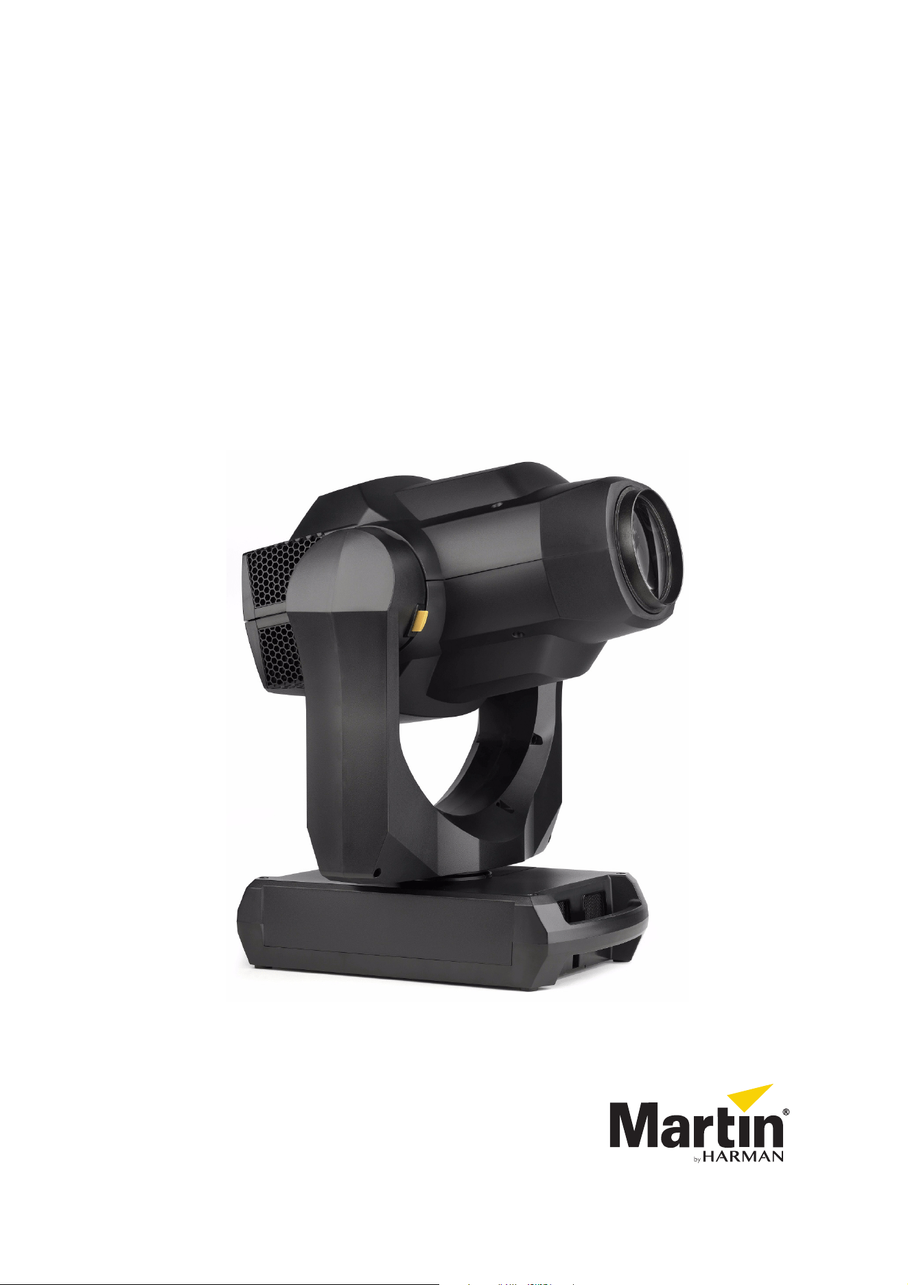
MAC Allure™ Profile
Safety and Installation Manual
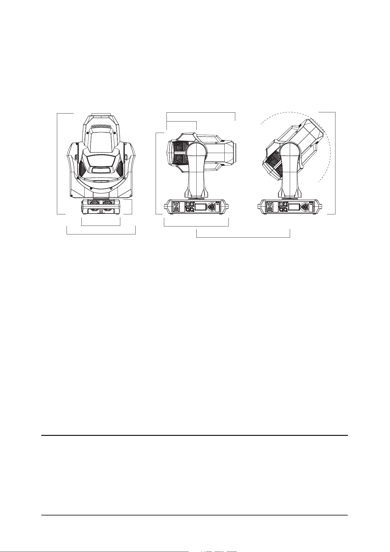
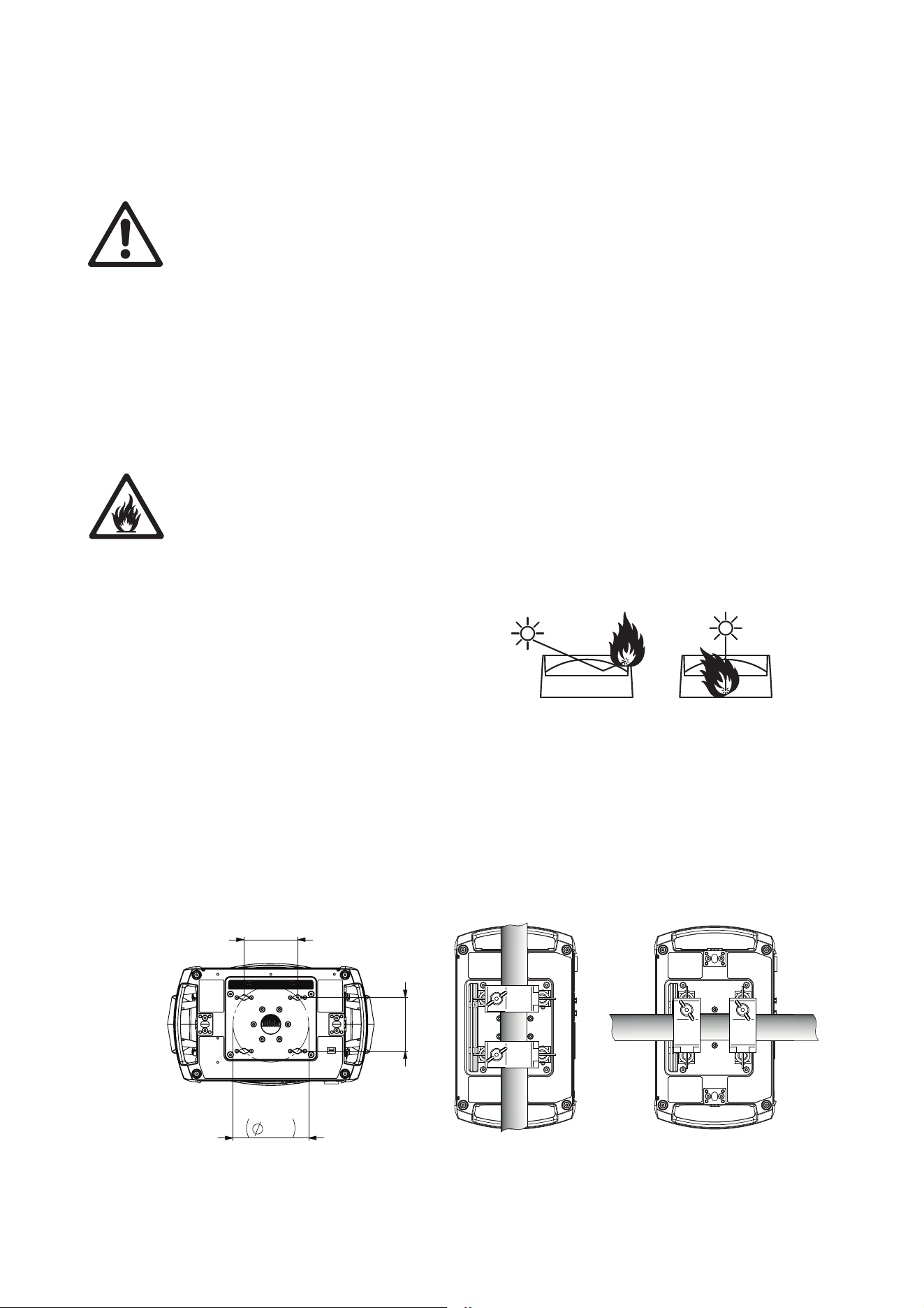
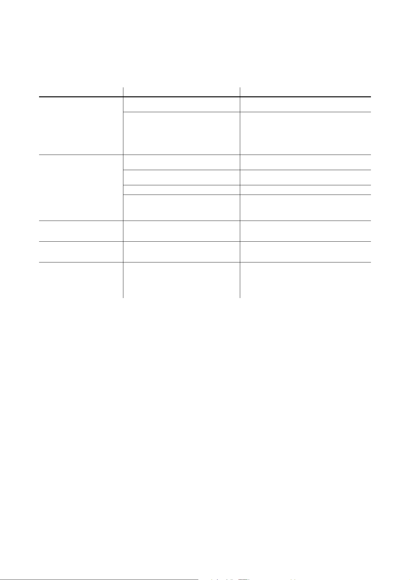
Dimensions
All measurements are given in millimeters
414
487
609
410
603
510
178
88
232
385
©2018 HARMAN PROFESSIONAL DENMARK ApS. All rights reserved. Features, specifications and appearance are subject to
change without notice. HARMAN PROFESSIONAL DENMARK ApS and all affiliated companies disclaim liability for any injury,
damage, direct or indirect loss, consequential or economic loss or any other loss occasioned by the use of, inability to use or reliance
on the information contained in this document. Martin is a registered trademark of HARMAN PROFESSIONAL DENMARK ApS
registered in the United States and/or other countries.
HARMAN PROFESSIONAL DENMARK ApS
, Olof Palmes Alle 44, 8200 Aarhus N, Denmark
HARMAN PROFESSIONAL SOLUTIONS U.S.
, 8500 Balboa Blvd., Northridge CA 91329, USA
www.martin.com
MAC Allure Profile Safety and Installation Manual, P/N 5107088-00, Rev. A

Contents
Safety Information. . . . . . . . . . . . . . . . . . . . . . . . . . . . . . . . . . . . . . . . . . . . . . . . . . . . . . . . . . . . . . . . . . 4
Introduction . . . . . . . . . . . . . . . . . . . . . . . . . . . . . . . . . . . . . . . . . . . . . . . . . . . . . . . . . . . . . . . . . . . . . . . . 7
Unpacking . . . . . . . . . . . . . . . . . . . . . . . . . . . . . . . . . . . . . . . . . . . . . . . . . . . . . . . . . . . . . . . . . . . . . . . . 7
Packing . . . . . . . . . . . . . . . . . . . . . . . . . . . . . . . . . . . . . . . . . . . . . . . . . . . . . . . . . . . . . . . . . . . . . . . . . . 7
Physical installation . . . . . . . . . . . . . . . . . . . . . . . . . . . . . . . . . . . . . . . . . . . . . . . . . . . . . . . . . . . . . . . . 8
AC power . . . . . . . . . . . . . . . . . . . . . . . . . . . . . . . . . . . . . . . . . . . . . . . . . . . . . . . . . . . . . . . . . . . . . . . . . 10
Power input . . . . . . . . . . . . . . . . . . . . . . . . . . . . . . . . . . . . . . . . . . . . . . . . . . . . . . . . . . . . . . . . . . . . . . 10
Data links . . . . . . . . . . . . . . . . . . . . . . . . . . . . . . . . . . . . . . . . . . . . . . . . . . . . . . . . . . . . . . . . . . . . . . . . . 12
DMX and RDM. . . . . . . . . . . . . . . . . . . . . . . . . . . . . . . . . . . . . . . . . . . . . . . . . . . . . . . . . . . . . . . . . . . . 12
Ethernet . . . . . . . . . . . . . . . . . . . . . . . . . . . . . . . . . . . . . . . . . . . . . . . . . . . . . . . . . . . . . . . . . . . . . . . . . 12
Service and maintenance. . . . . . . . . . . . . . . . . . . . . . . . . . . . . . . . . . . . . . . . . . . . . . . . . . . . . . . . . . 14
Tilt lock. . . . . . . . . . . . . . . . . . . . . . . . . . . . . . . . . . . . . . . . . . . . . . . . . . . . . . . . . . . . . . . . . . . . . . . . . . 14
Cleaning. . . . . . . . . . . . . . . . . . . . . . . . . . . . . . . . . . . . . . . . . . . . . . . . . . . . . . . . . . . . . . . . . . . . . . . . . 14
Lubrication . . . . . . . . . . . . . . . . . . . . . . . . . . . . . . . . . . . . . . . . . . . . . . . . . . . . . . . . . . . . . . . . . . . . . . . 15
Gobo replacement . . . . . . . . . . . . . . . . . . . . . . . . . . . . . . . . . . . . . . . . . . . . . . . . . . . . . . . . . . . . . . . . . 15
Battery replacement. . . . . . . . . . . . . . . . . . . . . . . . . . . . . . . . . . . . . . . . . . . . . . . . . . . . . . . . . . . . . . . . 20
Using the fixture. . . . . . . . . . . . . . . . . . . . . . . . . . . . . . . . . . . . . . . . . . . . . . . . . . . . . . . . . . . . . . . . . . . 21
Applying power . . . . . . . . . . . . . . . . . . . . . . . . . . . . . . . . . . . . . . . . . . . . . . . . . . . . . . . . . . . . . . . . . . . 21
Troubleshooting . . . . . . . . . . . . . . . . . . . . . . . . . . . . . . . . . . . . . . . . . . . . . . . . . . . . . . . . . . . . . . . . . . 22
Specifications . . . . . . . . . . . . . . . . . . . . . . . . . . . . . . . . . . . . . . . . . . . . . . . . . . . . . . . . . . . . . . . . . . . . . 23
4 MAC Allure Profile Safety and Installation Manual
Safety Information
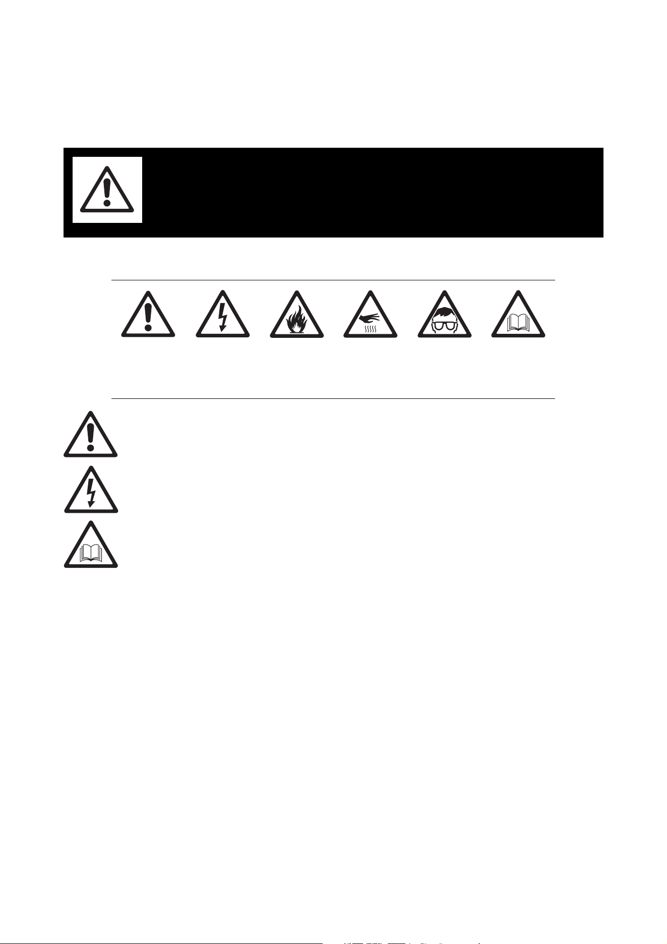
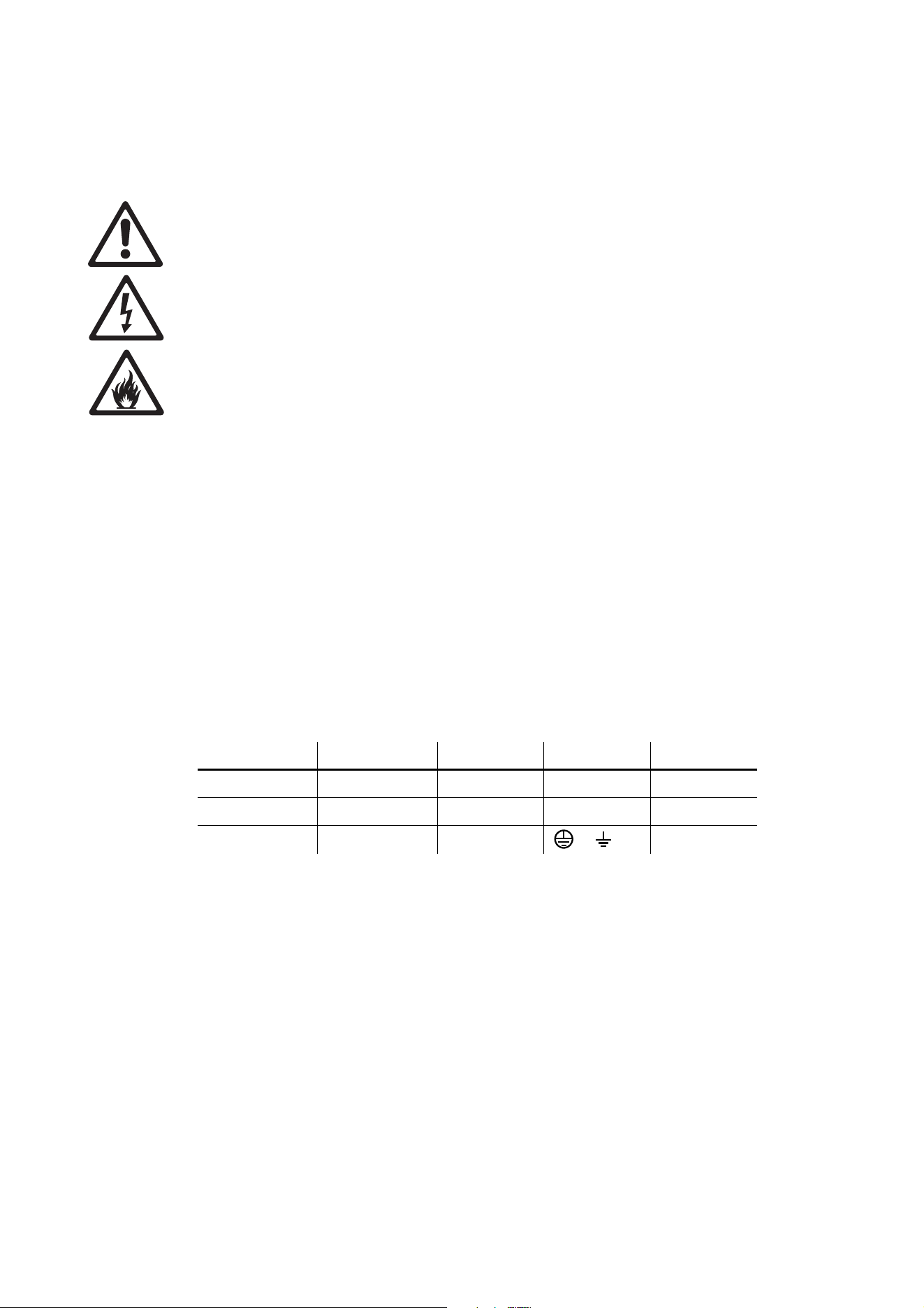
The following symbols are used to identify important safety information on the product and in this document:
Warning! The MAC Allure™ Profile from Martin® contains components that are accessible and live
at high voltage while the fixture is connected to power. These components remain under tension for
up to 30 minutes after power is disconnected. Only technicians who are authorized by Martin and
who have access to the Martin service documentation for the MAC Allure Profile are permitted to
open the fixture.
Warning! Risk Group 3 product according to EN 62471, IEC/TR 62778. This product produces
intense light output that may be hazardous if suitable precautions are not taken. Do not view the
light output with optical instruments or any device that may concentrate the beam.
This product presents risks of severe injury or death due to fire and burn hazards, electric shock and falls if
the safety precautions in this manual are not followed.
Read this manual before installing, powering or servicing the fixture. Follow the safety precautions and
observe all warnings in this manual, in the MAC Allure Profile User Guide, and printed on the fixture.
The latest versions of this Safety and Installation Manual and the MAC Allure Profile User Guide are
available for download from the MAC Allure Profile area of the Martin website at www.martin.com. Before
you install, operate or service the MAC Allure Profile, check the Martin website and make sure that you have
the latest user documentation for the fixture. Document revisions are indicated at the bottom of page 2.
This product is for professional use only. It is not for household use. Respect all locally applicable laws,
codes and regulations when installing, powering, operating or servicing the fixture.
Install, operate and service Martin products and accessories only as directed in their user documentation,
or you may create a safety hazard or cause damage that is not covered by product warranties.
The latest software, manuals and other documentation for all Martin products are available for download at
www.martin.com
Technical Support
If you have questions about how to install or operate the fixture safely, please contact Harman Professional
Technical support:
• For technical support in North America, please contact: HProTechSuppor[email protected]
Phone: (844) 776-4899
• For technical support outside North America, please contact your national distributor.
WARNING!
Read the safety precautions in this section before
installing, powering, operating or servicing this
product.
DANGER!
Safety hazard.
Risk of severe
injury or death.
DANGER!
Hazardous
voltage. Risk of
lethal or severe
electric shock.
WARNING!
Fire hazard.
WARNING!
Burn hazard. Hot
surface. Do not
touch.
WARNING!
Intense light
emission.
WARNING! Refer
to user
documentation.
Safety Information 5
PROTECTION FROM ELECTRIC SHOCK
• Do not expose the fixture to rain or moisture.
• Do not remove any cover from the fixture except as described under “Service and maintenance” on
page 14.
• Disconnect the fixture from AC power before servicing it and when it is not in use.
• Ensure that the fixture is electrically connected to ground (earth).
• Use only a source of AC power that complies with local building and electrical codes and has both
overload and ground-fault (earth-fault) protection.
• The fixture accepts AC mains power at 100-120/200-240 V (nominal), 50/60 Hz. Do not connect the
fixture to power that is not within this range.
• The voltage and frequency at the power throughput socket are the same as that applied at the power input
socket.
• Do not connect devices to power in a chain that will exceed the electrical ratings of any cable or connector
used in the chain.
• If you relay power from one fixture to another using power throughput sockets, observe the following
safety limits, or you may create a risk of fire and electric shock:
- Do not connect more than three MAC Allure Profile fixtures in total to each other in an interconnected
chain when supplying the fixture with mains power from 100 V to 120 V.
- Do not connect more than six MAC Allure Profile fixtures in total to each other in an interconnected
chain when supplying the fixture with mains power from 200 V to 240 V.
• Connect only other MAC Allure Profile fixtures to the power throughput socket. Do not connect any other
type of device to this socket.
• Power input and throughput cables must be rated 20 A minimum, 12 AWG or 2.5 mm
2
minimum
conductor size and heat-resistant to 90° C (194° F) minimum. Cables must have three conductors and an
outer cable diameter of 6 - 12 mm (0.24 - 0.47 in.). In North America the cable must be
UL/CSA-recognized, hard usage, type SJT, SJOOW or better. In the EU, the cable must be type
HO5VV-F, H07RN-F or better.
• Connect only a Neutrik powerCON TRUE1 NAC3FX-W type cable connector to the power input socket.
Connect only a Neutrik powerCON TRUE1 NAC3MX-W type cable connector to the power throughput
socket.
• Before using the fixture, check that all power distribution equipment and cables are in perfect condition
and rated for the current requirements of all connected devices.
• Isolate the fixture from power immediately if the power plug or any seal, cover, cable, or other component
is damaged, defective, deformed, wet or showing signs of overheating. Do not reapply power until repairs
have been completed.
• The MAC Allure Profile contains components that are accessible and live at high voltage while the fixture
is connected to power and that remain under tension for 30 minutes after power is disconnected. Only
technicians who are authorized by Martin and who have the Martin service documentation for the MAC
Allure Profile are permitted to open the fixture.
• Refer any service operation not described in this manual or in the MAC Allure Profile User Guide to Martin
Service or an authorized Martin Service partner.
• The light source contained in this fixture shall be replaced by Martin Service or an authorized Martin
Service partner only.
PROTECTION FROM BURNS AND FIRE
• The exterior of the fixture becomes hot during use. After 5 minutes of operation a surface temperature of
70° C (158° F) shall be expected. The maximum steady state surface temperature is also 70° C (158° F).
Avoid contact by persons and materials.
• Allow the fixture to cool for at least 30 minutes before handling.
• Keep all combustible materials (e.g. fabric, wood, paper) at least 0.2 m (8 in.) away from the fixture.
• Keep flammable materials well away from the fixture.
• Ensure that there is free and unobstructed airflow around the fixture.
• Provide a minimum clearance of 0.2 m (8 in.) around fans and air vents.
• Do not illuminate surfaces within 1.0 m (3.3 ft.) of the fixture.
• Do not expose the front glass to sunlight or any other strong light source from any angle. Lenses can
focus the sun's rays inside the fixture, creating a potential fire hazard.
• Do not attempt to bypass thermostatic switches or fuses.
• Do not operate the fixture if the ambient temperature (Ta) exceeds 40° C (104° F).
6 MAC Allure Profile Safety and Installation Manual
• Do not modify the fixture in any way not described in this manual or the fixture’s User Guide or install other
than genuine Martin parts. Do not stick filters, masks or other materials onto any lens or other optical
component. Use only accessories approved by Martin to mask or modify the light beam.
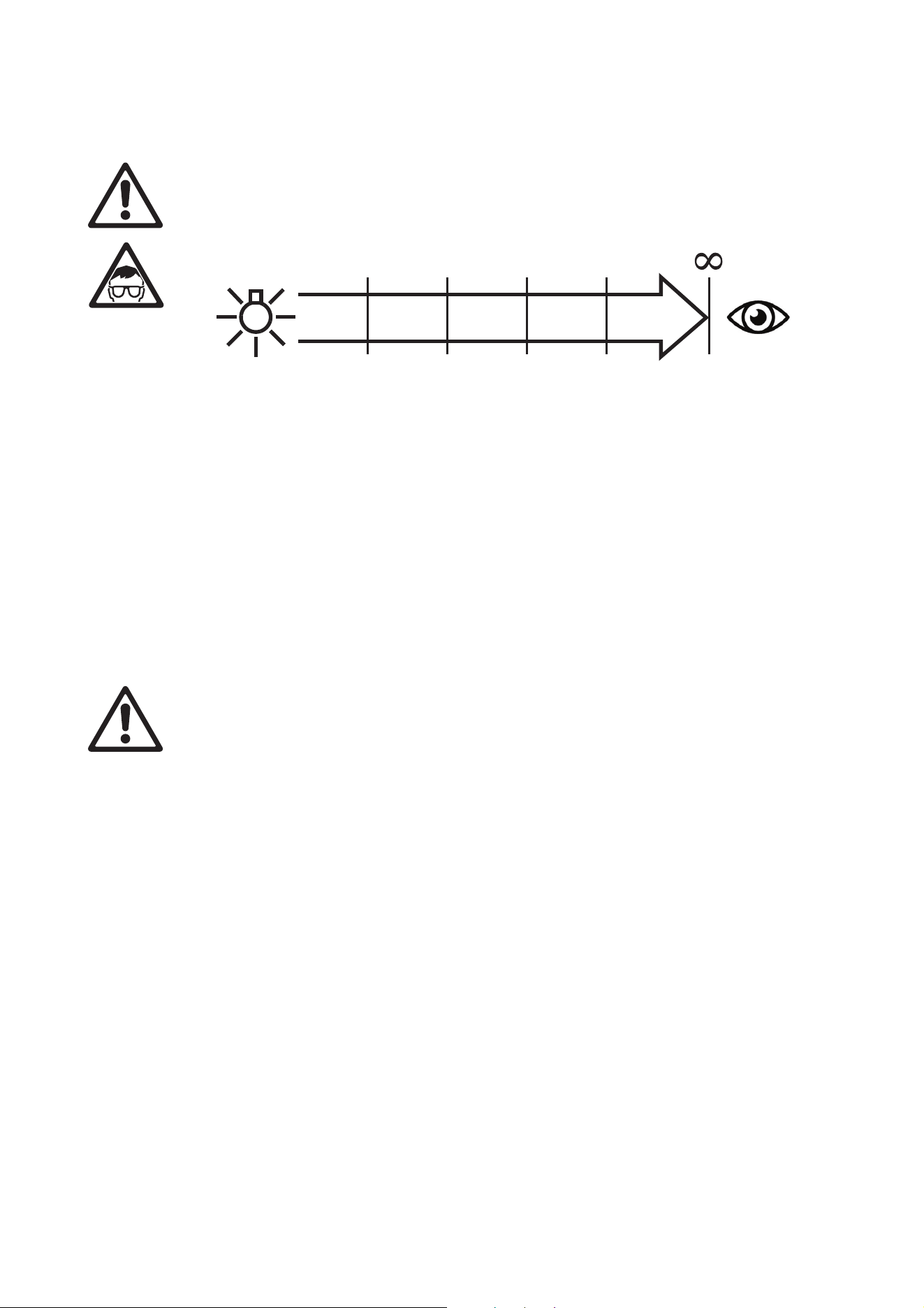
PROTECTION FROM EYE INJURY
• This fixture is a Risk Group 3 product according to EN 62471, IEC/TR 62778. It emits possibly hazardous
optical radiation. It falls into the Risk Group categories shown below according to EN 62471, IEC/TR
62778:
• At a distance of less than 6.6 m (21.7 ft.) from the fixture, the light output can potentially cause eye or skin
injury before an exposed person's natural aversion responses (blink reflex and reaction to skin discomfort)
can protect them. At distances greater than 6.6 m (21.7 ft.), potential eye and skin injury hazards from the
light output are normally prevented by natural aversion reflexes.
• Position the fixture so that persons cannot be exposed to the fixture's light output at a distance of less
than 6.6 m (21.7 ft.) from the fixture, and so that prolonged staring into the light output at less than 17.1 m
(56.1 ft.) from the fixture is not expected.
• Do not look directly into the fixture’s light output.
• Do not look at LEDs with magnifiers, telescopes, binoculars or similar optical instruments that may
concentrate the light output.
• Ensure that persons are not looking at the fixture when the fixture lights up suddenly. This can happen
when power is applied, when the fixture receives a DMX signal, or when certain control menu items are
selected.
• Disconnect the fixture from power at all times when the fixture is not in use.
• Provide well-lit conditions to reduce the pupil diameter of anyone working on or near the fixture.
PROTECTION FROM INJURY
• Fasten the fixture securely to a fixed surface or structure when in use. The fixture is not portable when
installed.
• Do not lift or carry the fixture alone.
• Use two evenly spaced omega brackets with clamps to suspend the fixture from rigging structures. Do not
use only one clamp.
• When clamping the fixture to a truss or other supporting structure, use two half-coupler clamps. Do not
use G-clamps, quick-trigger clamps or any other type of clamp that does not completely encircle the
supporting structure when fastened.
• When suspending the fixture, check that the supporting structure and all hardware used to suspend the
fixture can hold at least 10 times the weight of all devices suspended from them and that the installation
respects all similar safety factors that are required by locally applicable regulations. Check that the
structure and hardware are in perfect condition and suitable for their purpose.
• If the fixture is installed in a location where it may cause injury or damage if it falls, install as described in
this manual a secondary attachment such as a safety cable that is approved by an official body such as
TÜV as a safety attachment for the weight that it secures. The safety cable must comply with EN
60598-2-17 Section 17.6.6 or BGV C1 / DGUV 17, and must be capable of bearing a static suspended
load at least six times (or more if required by locally applicable regulations) the weight that it secures.
• Eliminate as much slack as possible in the safety cable (by looping it more than once around the rigging
truss, for example). Make sure that, if the primary attachment fails, the fixture cannot fall more than 20 cm
(8 inches) maximum before the safety cable catches it.
• If the safety cable attachment point becomes deformed, do not suspend the fixture. Have the fixture
repaired by an authorized Martin service partner.
• Check that all external covers and rigging hardware are securely fastened.
• Block access below the work area and work from a stable platform whenever installing, servicing or
moving the fixture.
• Allow enough clearance around the head to ensure that it cannot collide with a person or object such as
another fixture when it moves.
DO NOT RISK GROUP
3
RISK GROUP
2
0.2 m
(7.9 ins.)
6.6 m
(21.7 ft.)
17.1 m
(56.1 ft.)
USE
171 m
(561 ft.)
RISK GROUP
1
RISK GROUP
EXEMPT
Introduction 7
Introduction
Thank you for selecting the MAC Allure™ Profile from Martin®. This moving-head spotlight offers the
following features:
• Powerful RGBW LED engine
• RGB(W) color mixing and color temperature control
• Rotating gobo wheel
• Iris effect
• Rotating 4-facet prism
• Motorized zoom and focus
• Pre-programmed synchronizable FX (effect combination presets) including Animotion FX
• Full-range dimming with four dimming curve options
• Electronic shutter effect with variable speed regular and random strobe
• Backlit graphic display and battery power (mains power not required for fixture setup)
• Auto-sensing switch-mode power supply.
• Power daisy-chaining with Neutrik powerCON TRUE1 input and throughput connectors
For the latest firmware updates, documentation, and other information about this and all Martin products,
please visit the Martin website at http://www.martin.com
Comments or suggestions regarding this document may be e-mailed to service@martin.dk.
Unpacking
The MAC Allure Profile is packed in a cardboard box that is designed to protect the fixture during shipment.
Two packaging options are available in the cardboard box – the fixture can be supplied in either:
• expanded polystyrene that is not intended for re-use, or
• a SIP (Superior Impact Protection) insert that is designed to be installed in the 3-unit Martin MAC Allure
flightcase or custom-made flightcases.
This Safety and Installation Manual is included with the fixture. The MAC Allure Profile User Guide,
containing full details of setting up, controlling and monitoring the fixture, is available for download from the
MAC Allure Profile area of the Martin website at www.martin.com. If you have any difficulty locating this
document, please contact your Martin supplier for assistance.
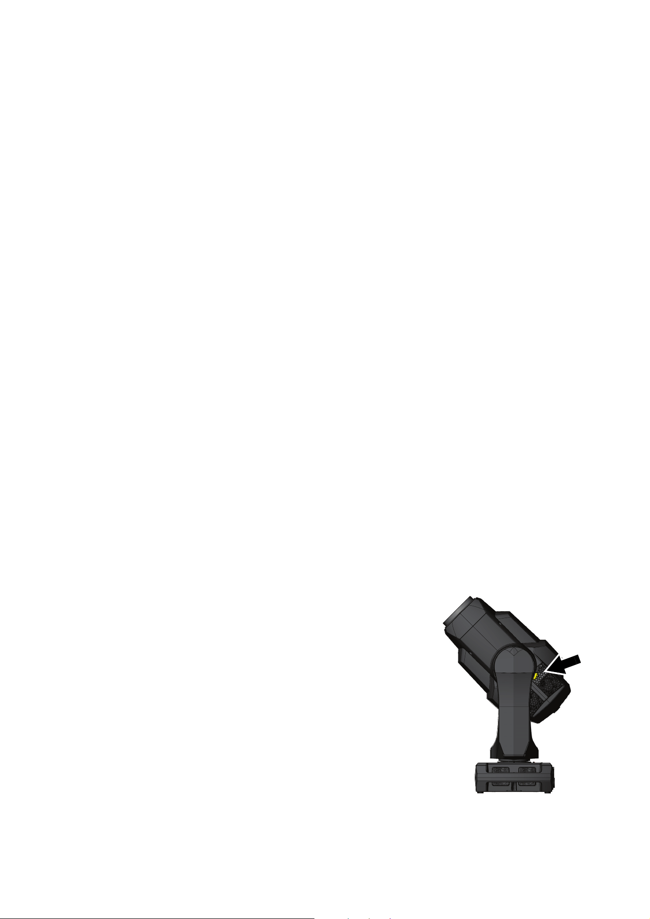
Tilt lock
Release the tilt lock before applying power to the fixture.
See Figure 1. Release the tilt lock by pushing the lock in towards the
yoke (you can reapply the tilt lock by first checking that the power is
off and then pushing the lock back in towards the yoke from the other
side).
Packing
Important! Allow the fixture to cool and release the tilt lock before packing
it in its flightcase.
A rugged three-unit flightcase is available from Martin for the MAC
Allure Profile. The flightcase accepts durable molded SIP (Superior
Impact Protection) foam inserts that are supplied in cardboard boxes
with fixtures if you select the SIP option at time of ordering.
The SIP inserts are designed to protect the head without the tilt lock
(see Figure 1) applied. Release the tilt lock before putting a fixture into a flightcase for transport. Leaving the
tilt lock applied may cause damage that is not covered by the product warranty.
Figure 1: Tilt lock
8 MAC Allure Profile Safety and Installation Manual
Physical installation
Warning! The MAC Allure Profile has a powerful pan motor. The torque reaction when the head is
panned suddenly can cause the base to move if the fixture is standing unsecured on a surface. Do
not apply power to the MAC Allure Profile unless the base is securely fastened to a surface or to
rigging hardware.
Warning! Use two clamps to rig the fixture. Do not hang the fixture from only one clamp. Lock each
clamp with both 1/4-turn fasteners. Fasteners are locked only when turned a full 90° clockwise.
Warning! When suspending the fixture above ground level, secure it against failure of primary
attachments by attaching a safety wire that is approved as a safety attachment for the weight of the
fixture to the attachment point in the base. Do not use the carrying handles for secondary
attachment.
Warning! When clamping the fixture to a truss or other structure at any other angle than with the
yoke hanging vertically downwards, use two clamps of half-coupler type. Do not use any type of
clamp that does not completely encircle the structure when fastened.
Warning! Position or shade the head so that the front lens will not be exposed to sunlight or another
strong light source from any angle – even for a few seconds. See Figure 2. The MAC Allure Profile’s
lens can focus the sun's rays, creating a potential fire hazard and causing damage.
Important! Do not point the output from other lighting fixtures at the MAC Allure Profile, as powerful
light can damage the display.
See Figure 2. Lenses can focus sunlight and
strong light, presenting a risk of fire and
damage to the fixture. Shield or shade the
head if necessary.
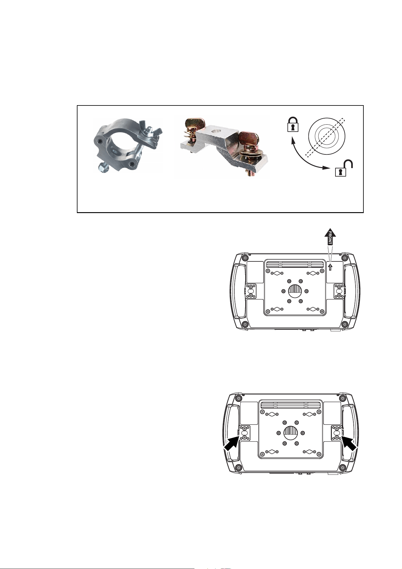
The MAC Allure Profile can be fastened to a surface such as a stage or clamped to a truss in any
orientation. Clamps must be half-coupler type (see Figure 4) or equivalent type that fully encircles the truss
unless the fixture is installed with the yoke hanging vertically downwards, in which case other clamp types
that are approved for the supported weight may be used.
The mounting points in the base allow omega brackets and rigging clamps to be fastened as shown in
Figure 3.
Figure 2: Potential sunlight damage
Figure 3: Clamp bracket positions
Physical installation 9
Clamping the fixture to a truss
1. Check that all rigging hardware is undamaged and can bear at least 10 times the weight of the fixture or
as required by locally applicable regulations. Check that the supporting structure can safely bear the
weight of all installed fixtures, clamps, cables, auxiliary equipment, etc. and complies with locally
applicable regulations.
2. Bolt each rigging clamp securely to an omega bracket with an M12 bolt (minimum grade 8.8) and
self-locking nut.
3. See Figure 3 on page 8. Align the first clamp
and bracket with 2 mounting points in the base,
and engage both the clamp bracket’s
quarter-turn fasteners in corresponding sockets
in the base. See Figure 4. Turn the levers on
the quarter-turn fasteners a full 90° clockwise
to lock. Repeat for the second clamp.
4. Block access under the work area. See Figure
5. Note the position of the arrow marked
FRONT on the base of the fixture. Working
from a stable platform, hang the fixture on the
truss with the arrow marked FRONT facing
towards the area to be illuminated. Tighten the
rigging clamps.
5. See Figure 6. Install a safety cable that is
approved as a safety attachment for the weight
of the fixture by looping it through a safety
attachment point (arrowed) in the bottom of the
base and around a secure anchoring point so
that the safety cable will catch the fixture if a primary attachment fails. Remove as much slack as
possible from the safety cable (by looping it more than once around the truss bar, for example).
6. Check that the tilt lock is released. Check that
there are no combustible materials within 0.2 m
(8 in.) or surfaces to be illuminated within 1.0 m
(3.3 ft.) of the fixture, and that there are no
flammable materials nearby.
7. Check that there is no possibility of heads or
yokes colliding with other fixtures.
8. Check that other lighting fixtures cannot project
light at the MAC Allure Profile, as powerful
illumination can damage the fixture’s display.
Figure 4: Martin rigging hardware
Half-coupler Omega bracket for
rigging clamp rigging clamp attachment
90°
Locking quarter-
turn fasteners
SAFETY CABLESAFETY CABLE
Figure 5: Front of fixture
SAFETY CABLESAFETY CABLE
Figure 6: Safety cable attachment points
10 MAC Allure Profile Safety and Installation Manual
AC power
Warning! Read “Safety Information” on page 4 before connecting the fixture to AC mains power.
For protection from electric shock, the fixture must be electrically connected to ground (earth). The
AC mains power distribution circuit must be equipped with a fuse or circuit breaker and ground-fault
(earth-fault) protection.
Power input
Important! Connect the MAC Allure Profile directly to AC power. Do not connect it to a dimmer
system; doing so may damage the fixture.
The MAC Allure Profile features an auto-sensing switch-mode power supply that automatically adapts to AC
mains power at 100-120/200-240 V (nominal), 50/60 Hz. Do not connect the fixture to power that is not
within this range.
The MAC Allure Profile requires a power input cable with a Neutrik powerCON TRUE1 NAC3FX-W female
cable connector for AC mains power input. The cable must meet the requirements listed under “Protection
from electric shock” on page 5. Martin can supply suitable cables with female TRUE1 input connectors
1.5 m (4.9 ft.) or 5 m (16.4 ft.) long. Alternatively, Martin can supply loose female TRUE1 input connectors
(see “Accessories” on page 34).
Connection to an AC mains power source
The power cable can be hard-wired to a building installation circuit or fitted with a mains plug (cord cap) to
allow connection to local AC mains power outlets.
If you install a mains plug on the power cable, install a grounding-type (earthed) plug rated minimum 16A,
250 V (example rating: EN 60309-2 CEE 2P+E 16A/250VAC), following the plug manufacturer’s
instructions. Table 1 shows some possible mains power pin identification schemes; if the pins are not clearly
identified, or if you have any doubts about proper installation, consult a qualified electrician.
If you need to install a Neutrik powerCON TRUE1 connector on a power cable, follow the instructions on the
Neutrik website at www.neutrik.com.
Linking fixtures to power in a chain
If you obtain a 12 AWG / 2.5 mm
2
power input cable and 12 AWG / 2.5 mm
2
power relay cables from Martin
(see “Accessories” on page 25), you can relay mains power from one fixture to another by connecting
fixtures to power in a linked daisy-chain, MAINS OUT throughput socket to MAINS IN input socket. If you
create a linked daisy-chain like this, you must respect the following safety limits, or you may create a risk of
fire and electric shock:
Using 12 AWG / 2.5 mm
2
cables from Martin, you can link:
• maximum three (3) MAC Allure Profile fixtures total in one chain at 100-120 V, or
• maximum six (6) MAC Allure Profile fixtures total in one chain at 200-240 V.
Wire Color (US) Wire Color (EU) Pin Symbol Screw (US)
black brown live L yellow or brass
white blue neutral N silver
green yellow/green ground (earth) or green
Table 1: Cord cap (mains plug) connections
AC power 11
If you connect multiple fixtures to power in a daisy-chain, we recommend that you draw power from a circuit
that is protected by a type D MCB (Miniature Circuit Breaker). This will avoid the breaker tripping
unnecessarily because of inrush current. If the only available power circuits have type C MCBs, you may
need to connect maximum four (4) fixtures per daisy-chain at 200-240 V in order to avoid tripping breakers
unnecessarily.
Connecting to power
Warning! The MAC Allure Profile does not have a power On/Off switch. As soon as you connect an
energized power input cable to the fixture or apply power to a power input cable that has already been
connected, the fixture will power up: check that there is no safety risk from head movement or intense light
output.
To apply power to the MAC Allure Profile:
1. Check that the tilt lock is released and that the base is held securely. Be prepared for the fixture to light
up and the head to move suddenly when power is applied.
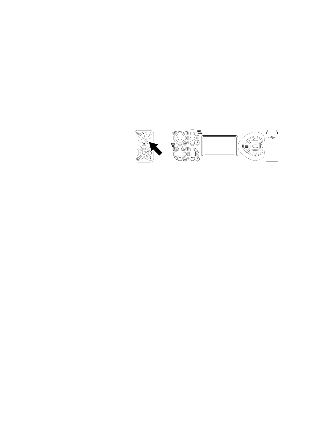
2. See Figure 7. line up the keys
in the power input cable’s
TRUE1 connector with the
keyways in the MAINS IN
socket (arrowed). Insert the
connector into the socket and
twist clockwise to engage. If
the connector seems difficult
to twist, remove it from the
socket, check that you have
lined up the keyways correctly
and try again – do not use excessive force. Make sure that the connector latch clicks and that the
connector is locked into the socket.
3. Apply power to the power input cable to power the fixture on.
To disconnect the MAC Allure Profile from power, pull the yellow latch on the connector towards you to
unlock the connector, twist the connector counter-clockwise, and then withdraw it from the MAINS IN
socket.
Figure 7: Mains input socket
12 MAC Allure Profile Safety and Installation Manual
Data links
Important! Shut down power to the fixture before connecting to or disconnecting from data.
DMX and RDM
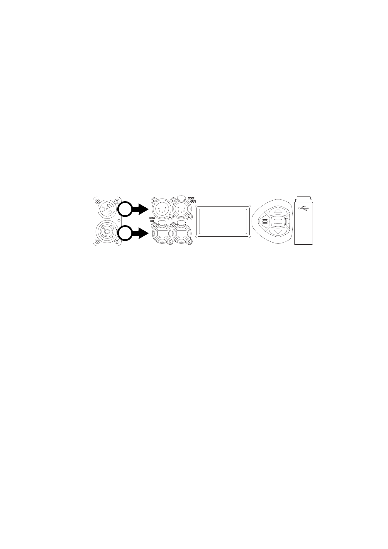
The MAC Allure Profile has 5-pin locking XLR sockets for DMX and RDM input and output (see A in Figure
8). The default pin-out on both sockets is:
• pin 1 to shield
• pin 2 to data 1 cold (-)
• pin 3 to data 1 hot (+).
Pins 4 and 5 are not used by the fixture but are bridged between input and output sockets. These pins can
therefore be used as a pass-through connection for an additional data signal if required.
Tips for reliable data transmission
• Use shielded twisted-pair cable designed for RS-485 devices: standard microphone cable cannot transmit
control data reliably over long runs. 24 AWG cable is suitable for runs up to 300 meters (1000 ft). Heavier
gauge cable and/or an amplifier is recommended for longer runs.
• To split the data link into branches, use a Martin RDM 5.5 Splitter optically isolated splitter-amplifier (see
“Related Items” on page 25).
• Do not overload the DMX data link. You can connect up to a maximum of 32 devices on a serial DMX link.
• Install a DMX termination plug on the last fixture on the link.
Connecting to data via DMX cable
To connect the MAC Allure Profile to DMX and/or RDM data carried over DMX cable:
1. Shut down power to the fixture.
2. Connect the DMX data output from the controller to the MAC Allure Profile’s data input (male XLR)
socket using good-quality DMX cable.
3. Run DMX cable from the MAC Allure Profile’s data output (female XLR) socket to the data input of the
next fixture and continue until the link is complete.
4. Terminate the data link by connecting a 120 Ohm, 0.25 Watt resistor between the data 1 hot (+) and cold
(-) conductors at the data output of the last fixture on the link. If the link is divided into branches using a
DMX splitter, terminate each branch of the link.
5. You can now apply power.
Ethernet
The MAC Allure Profile has Neutrik etherCON data sockets (see B in Figure 8) that support DMX and RDM
over Art-Net and sACN as well as Martin P3 video (see Figure 7 on page 11). Either socket can be used for
input and the other socket used for throughput.
Figure 8: Data connections
A
B

Data links 13
The etherCON data sockets have a fail-safe bypass feature. This means that the fixture will relay a data
signal from the socket used for input to the socket used for throughput even if power to the fixture is shut
down or lost.
Connecting to data via Ethernet cable
To connect the MAC Allure Profile to DMX, RDM and/or P3 video data carried over Ethernet cable using
Art-Net, streaming ACN or P3 video protocols:
1. Shut down power to the fixture.
2. Connect the Ethernet cable to either of the fixture’s EtherCON data sockets.
3. Run Ethernet cable from the fixture’s other EtherCON data socket to a data socket on the next fixture.
4. Continue connecting data sockets as described above until the link is complete.
5. You can now apply power.
14 MAC Allure Profile Safety and Installation Manual
Service and maintenance
Warning! Read “Safety Information” on page 4 before servicing the MAC Allure Profile.
Warning! Disconnect the fixture from AC mains power and allow to cool for at least 30 minutes
before handling. Do not stare into the light output. Be prepared for the fixture to light and move
suddenly when connected to power.
Warning! The MAC Allure Profile contains components that are accessible and live at high voltage
while the fixture is connected to power and that remain under tension for 30 minutes after power is
disconnected. Only technicians who are authorized by Martin and who have the Martin service
documentation for the MAC Allure Profile are permitted to open the fixture. Users may carry out
external cleaning as described in this section, following the warnings and instructions provided, but
any service operation not described in this manual or in the fixture’s User Guide must be referred to
a qualified service technician.
Important! Excessive dust, smoke fluid, and particle buildup degrades performance, causes
overheating and will damage the fixture. Damage caused by inadequate cleaning or maintenance is
not covered by the product warranty.
The user must clean the MAC Allure Profile periodically to maintain optimum performance and cooling. The
user may also upload firmware (fixture software) to the fixture via the DMX data input port, USB port or
Ethernet port using firmware and instructions from Martin. All other service operations on the MAC Allure
Profile must be carried out by Martin, its approved service agents or trained and qualified personnel using
the official Martin service documentation for the MAC Allure Profile.
Installation, on-site service and maintenance can be provided worldwide by the Martin Professional Global
Service organization and its approved agents, giving owners access to Martin’s expertise and product
knowledge in a partnership that will ensure the highest level of performance throughout the product’s
lifetime. Please contact your Martin supplier for details.
It is Martin policy to apply the strictest possible calibration procedures and use the best quality materials
available to ensure optimum performance and the longest possible component lifetimes. However, optical
components are subject to wear and tear over the life of the product, resulting in gradual changes in color
over many thousands of hours of use. The extent of wear and tear depends heavily on operating conditions
and environment, so it is impossible to specify precisely whether and to what extent performance will be
affected. However, you may eventually need to replace optical components if their characteristics are
affected by wear and tear after an extended period of use and if you require fixtures to perform within very
precise optical and color parameters.
Tilt lock
The tilt position of the head can be locked for service. See Figure 1 on page 7. Push the lock in towards the
yoke in one direction to lock the head and back in from the other side to unlock the head.
Important! Release the tilt lock before applying power to the fixture and before packing the fixture in its
flightcase.
Cleaning
Regular cleaning is very important for fixture life and performance. Buildup of dust, dirt, smoke particles, fog
fluid residues, etc. degrades the fixture’s light output and cooling ability.
Cleaning schedules for lighting fixtures vary greatly depending on the operating environment. It is therefore
impossible to specify precise cleaning intervals for the MAC Allure Profile. Cooling fans suck in airborne
dust and smoke particles, and in extreme cases fixtures may require cleaning after surprisingly few hours of
operation. Environmental factors that may result in a need for frequent cleaning include:
• Use of smoke or fog machines.
• High airflow rates (near air conditioning vents, for example).
• Presence of cigarette smoke.

Service and maintenance 15
• Airborne dust (from stage effects, building structures and fittings or the natural environment at outdoor
events, for example).
If one or more of these factors is present, inspect fixtures within their first few hours of operation to see
whether cleaning is necessary. Check again at frequent intervals. This procedure will allow you to assess
cleaning requirements in your particular situation. If in doubt, consult your Martin dealer about a suitable
maintenance schedule.
Follow these precautions when cleaning the fixture:
• Work in a clean, dry, well-lit area.
• Use gentle pressure only. Do not use any product that contains abrasives. Do not use solvents. Use care
when cleaning optical components: surfaces are fragile and easily scratched.
• Use a vacuum cleaner – do not use a pressurized air jet. A vacuum cleaner will remove dirt from the
fixture and from the area where you are working. An air jet may blow dirt into the fixture, and this can
cause visible objects in projections and possibly even damage to the fixture.
• Do not apply a strong vacuum directly to a cooling fan, as the strong airflow may spin the fan blades fast
enough to cause damage. Instead, hold the vacuum cleaner nozzle a few centimeters away from the fan
and dislodge dust with a soft brush.
Cleaning procedure
To clean the fixture:
1. Disconnect the fixture from power and allow it to cool for at least 30 minutes.
2. Vacuum dust and loose particles from the outside of the fixture and the air vents at the back and sides of
the head and in the base.
3. Clean the front glass on the front of the head by wiping gently with a soft, clean, lint-free cloth moistened
with a weak detergent solution. Do not rub the surface hard: lift particles off with a soft repeated press.
Dry with a soft, clean, lint-free cloth or low-pressure compressed air. Remove stuck particles with an
unscented tissue or cotton swab moistened with glass cleaner or distilled water.
4. Check that the fixture is dry before reapplying power.
Lubrication
The MAC Allure Profile does not require lubrication under normal circumstances. Moving parts can be
checked and a long-lasting teflon-based grease reapplied by a Martin service partner if necessary.
Gobo replacement
See the MAC Allure Profile User Guide, available for download from www.martin.com, for names,
illustrations and part numbers of the gobos installed as standard.
The MAC Allure Profile uses specially designed borosilicate 3.3 gobos with a heavy matted aluminum
coating. All gobos are interchangeable, but replacement gobos must match the dimensions, construction
and quality of the gobos supplied as standard. The gobos are a custom size: 27.9 mm external diameter,
24 mm image diameter.
Optical components have fragile coatings and are exposed to very high temperatures. Handle and store
components with care.
Avoiding damage to gobos
Follow these precautions when handling, using and storing gobos:
• Do not use gobos with dark coatings on either side, as these will absorb heat – either directly from the
light source or reflected back from other optical components – and will not be durable.
• Do not use metal gobos in the MAC Allure Profile: their durability may be reduced when used in this
fixture.
• Store all gobos in a dust-free environment with approx. 50% humidity.
• Wear clean, lint-free cotton gloves when handling gobos.
• Avoid scratching coated and uncoated sides.
• Do not place a gobo with the coated side face-down on any surface.
16 MAC Allure Profile Safety and Installation Manual
• Avoid touching the other gobos when removing a gobo from a rack: the sharp edge of one gobo can
scratch the others.
• Keep gobos perfectly clean to reduce the risk of heat damage.
• Clean the coated side of gobos with dust and oil-free compressed air only.
• Clean the uncoated side of gobos with photographic quality lens-cleaner and optics cleaning tissues. Use
a repeated dabbing action rather than a rubbing action.
• Correct gobo orientation is critical. Read the guidelines given later in this chapter carefully before
installing a gobo.
Opening the head for access
To open the head for access to the rotating gobos:
1. Disconnect the fixture from power and allow to cool for 30 minutes.
2. Place the fixture on a suitable work surface.
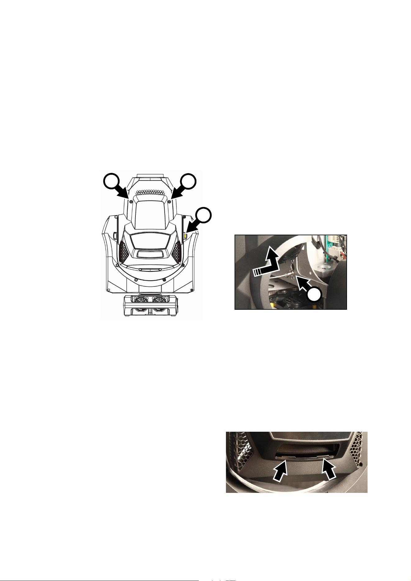
3. See Figure 9. Position the yoke so that the tilt lock button A is on the right of the head. With the tilt lock
button on the right, the bottom head cover is facing you. Apply the tilt lock.
4. Loosen the bottom cover’s two Torx 25 retaining screws B and lift the front of the cover away from the
head slightly. Then slide the cover towards the front of the head slightly to release the locating tabs at
the back of the cover and lift the cover away from the head.
5. You can allow the head cover to hang on its safety wire but you may find access easier if you remove the
cover. To do this, press the cover’s safety wire retaining clip C in towards the head chassis, slide the clip
until you can remove it, and then remove the head cover completely from the fixture.
To close the head:
1. If you unclipped the head cover safety wire,
reinstall it in its attachment point in the head
chassis.
2. See Figure 10. Note the position of the head
cover locating tabs. Slide the head cover
towards the back of the fixture so that the tabs
engage.
3. Reinstall the two head cover screws and check
that the head cover is held securely.
4. Release the tilt lock before reapplying power or
packing the MAC Allure Profile in its flightcase.
Figure 9: Removing the bottom head cover
B
B
C
A
Figure 10: Head cover locating tabs
Service and maintenance 17
Replacing a rotating gobo
To replace a rotating gobo:
1. Remove the bottom head cover as described in the previous section.
2. Turn the rotating gobo wheel until the gobo that you want to replace is easily accessible. Avoid turning
the gobo wheel from now until you have finished replacing the gobo. This will keep the gobos in their
correct orientation, avoiding the need to reprogram cues or adjust gobo positions in the fixture because
a gobo orientation has changed during service.
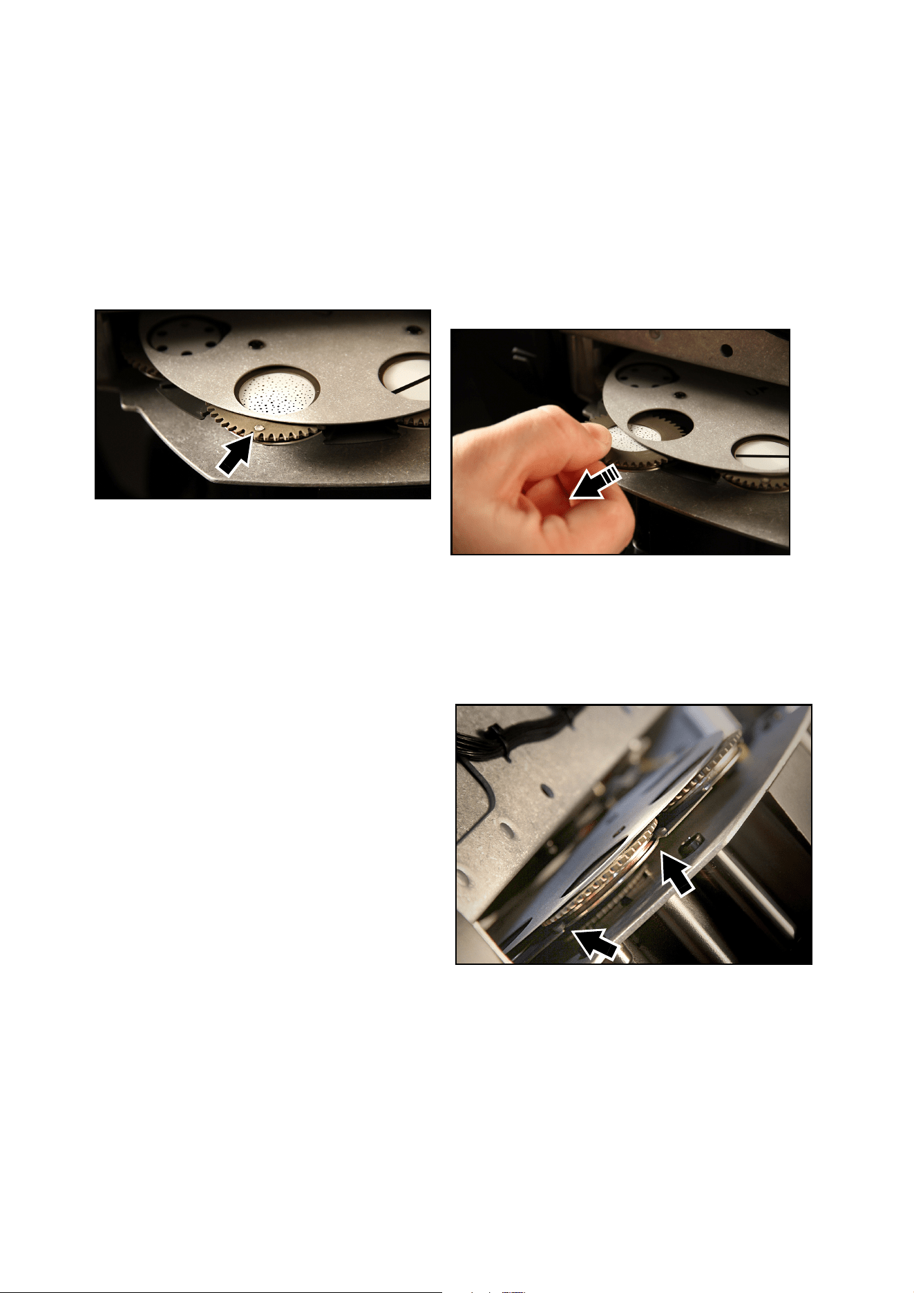
3. See Figure 11. Rotate the gobo that you want to replace until the magnet (arrowed) in the goboholder
points towards a reference position (facing towards you and directly out of the gobo wheel, for example).
The magnets in all the goboholders will now point in this direction.
4. Holding the edge of the goboholder firmly, slide the goboholder out of its clip in the gobo wheel as shown
in Figure 11.
5. To install a goboholder in the gobo
wheel See Figure 12. Check that the
magnets in all the goboholders are still
facing towards the reference point,
then slide the new goboholder into its
clip in the gobo wheel with the magnet
facing towards the reference point.
Make sure that the groove in the
goboholder slides into the goboholder
jaws (arrowed). Do not apply lubricant
to the groove or jaws. Excess grease
can cause loss of step.
6. Check that the gobo is held securely.
and rotates correctly.
7. When service work is finished,
reinstall the bottom head cover as
described above.
Figure 11: Removing a rotating gobo
Figure 12: Rotating gobo jaws
18 MAC Allure Profile Safety and Installation Manual
Installing a gobo in a goboholder
All the gobos in the MAC Allure Profile except one are held in their holders by springs and can be removed
from their holders as described below.
The exception is the fused glass gobo Limbo (Crystal). This gobo is glued into its goboholder and cannot be
removed from it. If you need to replace the Limbo gobo, you must replace the entire goboholder.
Uneven glass surfaces make textured glass gobos difficult to install securely using retaining springs.
Textured gobos must be glued into goboholders using suitable high-temperature glue.
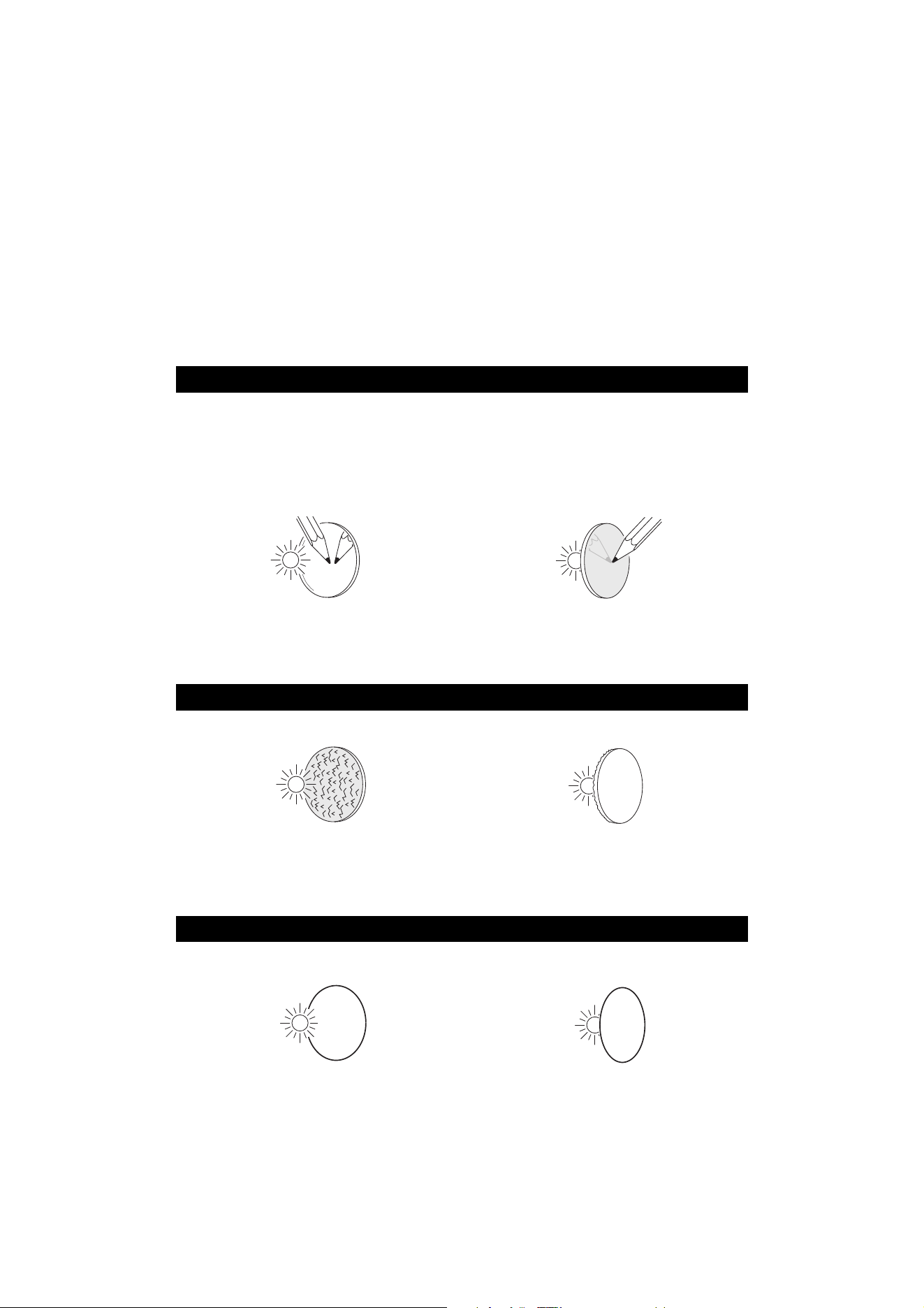
Gobo orientation
Make sure that you install gobos facing in the correct direction, or they may suffer heat damage. The
orientations shown in Figure 13 are correct in most cases, but consult your Martin dealer or gobo supplier if
you are in any doubt about the orientation of a specific gobo type.
Coated Glass Gobos
The heavy matted aluminum coated borosilicate gobos in the MAC Allure Profile are
factory-installed with the more reflective sides facing towards the LED light source.
Replacement gobos must also be installed with more reflective sides facing the LEDs in
order to avoid heat damage.
More reflective side towards LEDs
To minimize the risk of gobo overheating
and damage, turn the more reflective side of
a coated gobo towards the lamp.
Less reflective side away from LEDs
The less reflective side of a coated gobo will
absorb less heat if it faces away from the
lamp.
Textured Glass Gobos
Textured side towards LEDs Smooth side away from LEDs
Textured glass gobos in the MAC Allure Profile sit most squarely in the gobo wheel with the
textured side towards the LED light source. If in doubt, consult your Martin dealer or gobo
supplier. We recommend that textured glass gobos are glued into the goboholder.
Image / text Gobos
True image towards LEDs Reversed image away from LEDs
Gobos that have a specific left/right orientation (such as text gobos) will appear correctly in
the projection if they appear correctly when viewed from the side that faces towards the
LED light source.
Figure 13. Correct gobo orientation
abc
abc
abc
abc
Service and maintenance 19
In the MAC Allure Profile:
• The side of the goboholder with the gobo retaining spring faces towards the LED light source.
• The side of the goboholder with the teeth faces towards the front glass.
With the goboholder placed teeth down on a clean surface and the gobo retaining spring facing upwards as
shown in Figure 15, gobos in the MAC Allure Profile must be installed as follows:
• The shiny side must face upwards towards the spring in the goboholder. The white side must face
downwards.
• Images or text on gobos must appear correctly (and not flipped left to right) when looking down at the
goboholder from the side with the spring.
• The textured side of textured glass gobos must face upwards. The flat side of the gobo must face
downwards so that the gobo sits flat in the goboholder.
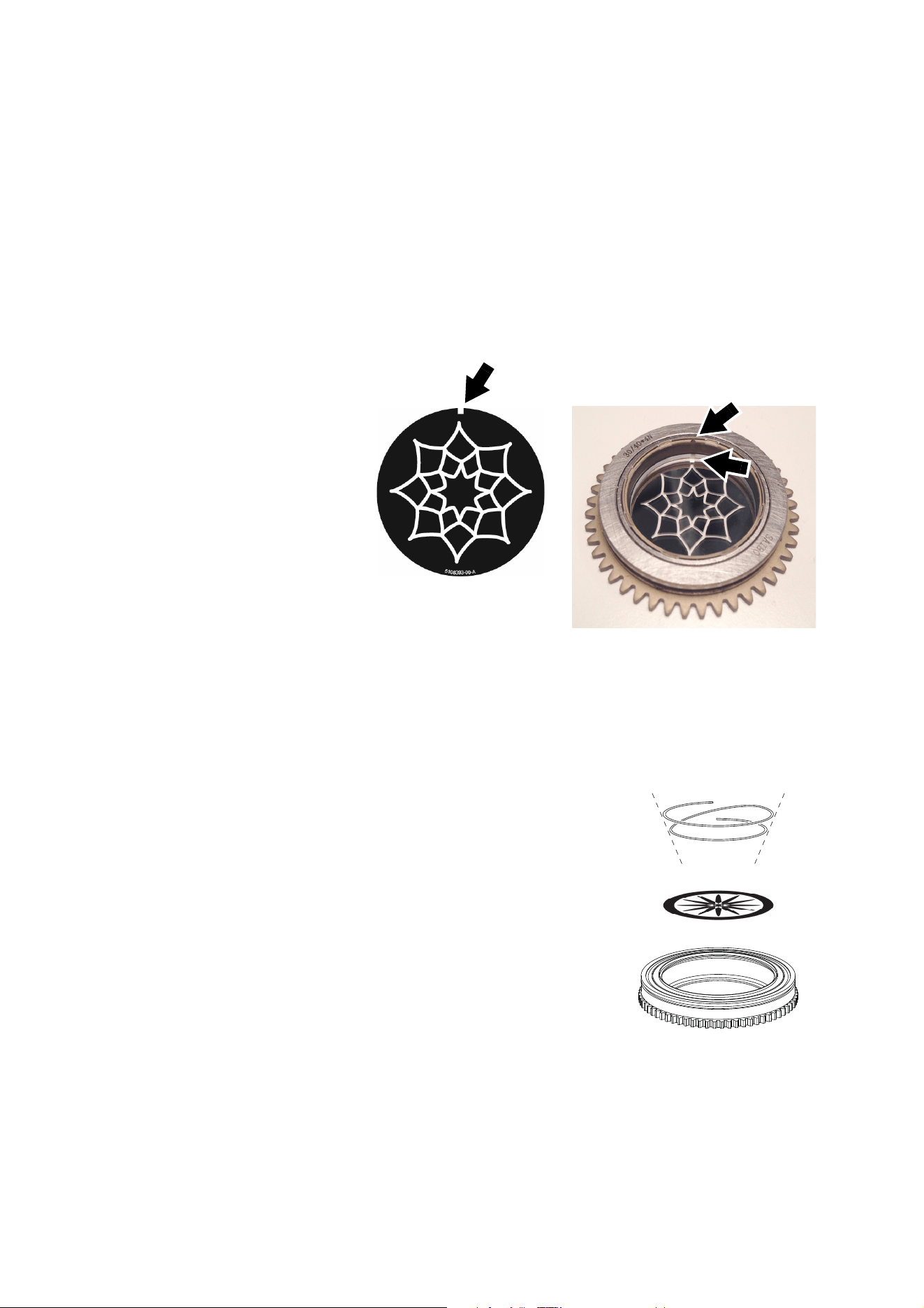
Gobo alignment
See Figure 14. Note the
position of the alignment
marks (arrowed) on gobos
and goboholders. Install
gobos with the alignment
marks next to each other
as shown.
Replacement procedure
Avoid getting grease from your fingers or dirt onto gobos. Hold gobos by their edges only. Wear clean,
lint-free cotton gloves if necessary.
To replace a gobo in a goboholder:
1. Note the position of the alignment marks on the existing gobo
and on the goboholder.
2. With a small screwdriver or similar tool, unhook the end of the
gobo spring furthest from the gobo and pull out the spring.
3. Turn the goboholder teeth side up and let the gobo fall out of the
holder onto a clean, soft surface.
4. Holding the new gobo by its edges, insert it into the goboholder
with the alignment marks on gobo and goboholder oriented
correctly and with the shiny side facing upwards, towards the
spring (see Figure 14 and Figure 15).
5. Insert the spring into the goboholder with the narrow end
pressing against the gobo as shown in Figure 15 (to identify the
narrow end, press the spring flat: the narrow end is on the
inside).
6. Check that the gobo is seated flush against the holder, then
push the wide end of the spring in under the lip of the holder.
7. Check that the spring is pressed as flat as possible against the
back of the gobo and that the spring now holds the gobo
securely in the goboholder.
Figure 14: Gobo alignment marks
Figure 15: Rotating gobo holder
shiny side up
20 MAC Allure Profile Safety and Installation Manual
Battery replacement
Warning! Disconnect the fixture from AC power before replacing its battery. Do not attempt to recharge the
battery, or you may create a risk of fire or explosion.
The MAC Allure Profile has a
non-rechargeable 3-volt lithium
battery that provides power to the
control panel and display when
the fixture is not connected to AC
mains power. If the battery runs
flat, you must replace it. Do not
attempt to recharge it.
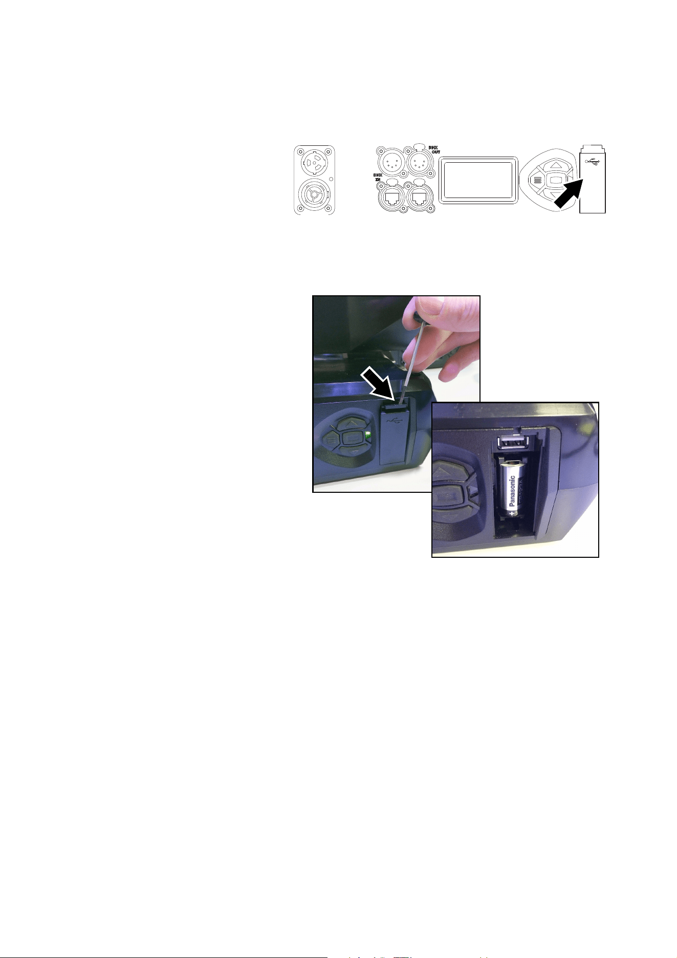
See Figure 16. The battery is
located in the USB port / battery
compartment next to the control
panel on the base of the fixture.
To replace the battery:
1. Order Martin P/N 05801011
(CR123A, 3 V lithium battery).
2. Disconnect the fixture from AC
mains power and allow to cool.
3. See Figure 17. Push down on
the locking tab (arrowed) with a
screwdriver to release the USB
port / battery compartment
cover and remove the cover.
4. Remove the used battery and
insert the new one, respecting
the correct battery polarity
(positive terminal facing
downwards, away from the
head).
5. Reinstall the compartment
cover and check that it is
closed securely before
reapplying power.
6. Dispose of the used battery
responsibly: send to an
authorized waste recycling and
disposal center.
Figure 16: Battery compartment
Figure 17: Battery compartment

Using the fixture 21
Using the fixture
Before using the fixture, download and read the latest version of the MAC Allure Profile User Guide from the
MAC Allure Profile area of the Martin website at www.martin.com. The User Guide contains details of:
• The effects available in the fixture.
• The control options available using DMX, RDM and/or P3.
• The setup, monitoring and control options available using the onboard control and display panel.
• Software service functions.
Applying power
Warning! Before applying power to the fixture:
• Read the safety information section of this manual starting on page 4.
• Read “Connecting to power” on page 11.
• Check that the installation is safe and secure.
• Check that the base is fastened securely so that the torque reaction when the head moves will not
cause the base to move.
• Check that the head tilt lock is released (see “Tilt lock” on page 7).
• Be prepared for the fixture to light up suddenly. Check that no-one is looking at the fixture from
close range.
• Be prepared for the head to move suddenly. Check that there will be no risk of collision with
persons or objects.
The MAC Allure Profile does not have an On/Off switch. To apply power to the fixture, apply power to the
power input cable.
22 MAC Allure Profile Safety and Installation Manual
Troubleshooting
Problem Probable cause(s) Remedy
One or more of the fixtures is
completely dead.
No power to fixture.
Check that power is switched on and cables are
plugged in.
Fuse blown or internal fault.
Contact Martin Service or authorized service
partner. Do not remove base or yoke covers,
attempt to replace a fuse or carry out any repairs or
service that are not described in this Safety and
Installation Manual unless you have both
authorization from Martin and official Martin service
documentation.
Fixtures reset correctly but
respond erratically or not at all
to the controller.
Bad data link.
Inspect connections and cables. Correct poor
connections. Repair or replace damaged cables.
Data link not terminated.
Insert DMX termination plug in data output socket
of the last MAC Allure Profile on the data link.
Incorrect addressing of fixtures. Check fixture address and protocol settings.
One of the fixtures is defective and is
disturbing data transmission on the link.
Unplug the XLR in and out connectors and connect
them directly together to bypass one fixture at a
time until normal operation is regained. Have the
fixture serviced by a qualified technician.
Timeout error after fixture reset. Effect requires mechanical adjustment.
Check fixture’s stored error messages for more
information. Contact Martin Service or authorized
Martin service partner.
Mechanical effect loses
position.
Mechanical train requires cleaning,
adjustment, or lubrication.
Check fixture’s stored error messages for more
information. Contact Martin Service or authorized
Martin service partner.
Light output cuts out
intermittently.
Fixture is too hot.
Check fixture’s stored error messages for more
information.
Allow fixture to cool.
Clean fixture.
Reduce ambient temperature.
Table 2: Troubleshooting

Specifications 23
Specifications
Physical
Length (head) . . . . . . . . . . . . . . . . . . . . . . . . . . . . . . . . . . . . . . . . . . . . . . . . . . . . . . . . . .414 mm (16.3 in.)
Length (base). . . . . . . . . . . . . . . . . . . . . . . . . . . . . . . . . . . . . . . . . . . . . . . . . . . . . . . . . . .385 mm (15.2 in.)
Width (across yoke) . . . . . . . . . . . . . . . . . . . . . . . . . . . . . . . . . . . . . . . . . . . . . . . . . . . . . .410 mm (16.2 in.)
Height (maximum) . . . . . . . . . . . . . . . . . . . . . . . . . . . . . . . . . . . . . . . . . . . . . . . . . . . . . . .609 mm (24.0 in.)
Height (head straight up) . . . . . . . . . . . . . . . . . . . . . . . . . . . . . . . . . . . . . . . . . . . . . . . . . .603 mm (23.8 in.)
Weight . . . . . . . . . . . . . . . . . . . . . . . . . . . . . . . . . . . . . . . . . . . . . . . . . . . . . . . . . . . . . . . 17.6 kg (38.8 lbs.)
Minimum center-to-center distance in side-by-side installation . . . . . . . . . . . . . . . . . . . . .510 mm (20.1 in.)
Dynamic Effects
Color mixing. . . . . . . . . . . . . . . . . . . . . . . . . . . . . . . . . . . . . . . . . .RGBW, independently variable 0 - 100%
Color temperature control . . . . . . . . . . . . . . . . . . . . . . . . . . . . . . . . . . . . . . . . . . . . Variable 2000 - 8000 K
Color wheel effect . . . . . . . . . . . . . . . . . . . . . . . . . Virtual, multiple colors, split colors and open, indexing,
continuous rotation, random color
Rotating gobo wheel . . . . . . . . . . . . . . . . . . . . . . . . . . 6 x interchangeable texture/breakup gobos + open,
indexing, continuous rotation and shake
Prism . . . . . . . . . . . . . . . . . . . . . . . . . . . . . . . . . . . . . . . . . . . . . . . . . . . . . . . . . . . . . . 4-facet, fully indexed
Iris . . . . . . . . . . . . . . . . . . . . . . . . . . . . . . . . . . . . . . . . . . . . . . . . . . . . . . . .Variable 0 - 100%, pulse effects
Dimmer/shutter . . . . . . . . . . . . . . . . . . . . . 0 - 100% continuous dimming, regular and random strobe and
pulse effects, instant open and blackout
Dimming options . . . . . . . . . . . . . . . . . . . . . . . . . . . . . . . . . . . . . . . . . . . . . Choice of four dimming curves
Pre-programmed effects . . . . . . . . . . . . . . . . . Two ranges of FX, independent or synchronized/combined
Focus . . . . . . . . . . . . . . .Range varies with zoom angle, from approx. 2 m (6.6 ft.) / 6 m (19.7 ft.) to infinity
Zoom . . . . . . . . . . . . . . . . . . . . . . . . . . . . . . . . . . . . . . . . . . . . . . . . . . . . . . . . . . . . . . . . . . . . . . . Motorized
Pan. . . . . . . . . . . . . . . . . . . . . . . . . . . . . . . . . . . . . . . . . . . . . . . . . . . . . . . . . . . . . . . . . . . . . . . . . . . . . 540°
Tilt . . . . . . . . . . . . . . . . . . . . . . . . . . . . . . . . . . . . . . . . . . . . . . . . . . . . . . . . . . . . . . . . . . . . . . . . . . . . . 268°
Position correction system . . . . . . . . . . . . . . . . . . . . . . . . . . . . . . . . . . . . . . . . Absolute position monitoring
Control and Programming
DMX channels . . . . . . . . . . . . . . . . . . . . . . . . . . . . . . . . . . . . . . . . . . . . 32 or 68 depending on DMX mode
Setting and addressing . . . . . . . . . . . . . . . . . . . . . . . . . . . . . . Control panel, RDM, RDM via Art-Net or P3
16-bit control . . . . . . . . . . . . . . . . . . . . . . . . . . . . . . . . . Dimming, rotating gobos, zoom, focus, pan and tilt
Movement control options . . . . . . . . . . . . . . . . . . . . . . . . . . . . . . . . . . . . . . . . . . . . . . . Tracking and vector
Fixture identification. . . . . . . . . . . . . . . . . . . . . . . . . . . . . . . . . . . . . . . . . . . . . . . . User-settable ID number
DMX compliance . . . . . . . . . . . . . . . . . . . . . . . . . . . . . . . . . . . . . . . . . . . . . . . . . . . . . . . USITT DMX512-A
RDM compliance . . . . . . . . . . . . . . . . . . . . . . . . . . . . . . . . . . . . . . . . . . . . . . . . . . . . . . . ANSI/ESTA E1.20
Art-Net compliance . . . . . . . . . . . . . . . . . . . . . . . . . . . . . Art-Net 1, 2, 3 and 4 including RDM over Art-Net
sACN compliance . . . . . . . . . . . . . . . . . . . . . . . . . . . . . . . . . . . . . . . . . . . . . . . . . . . . . . . . . . . ANSI E1.31
Martin P3 compliance . . . . . . . . . . . . . . . . . . . . . . . . . . . . . P3 System Controller Software 5.0.0 or newer
Ethernet Transceiver . . . . . . . . . . . . . . . . . . . . . . . . . . . . . . . . . . . . . . . . . . . . . . . . . . . . . . . . . 10/100 Mbit
DMX/RDM Transceiver . . . . . . . . . . . . . . . . . . . . . . . . . . . . . . . . . . . . . . . . . . . . . . . Opto-isolated RS-485
Fixture software update . . . . . . . . . . . . . . . . . . . .USB memory device, over DMX link or over Ethernet link
Optics
Zoom range . . . . . . . . . . . . . . . . . . . . . . . . . . . . . . . . . . . . . . . . . . . . . . . . . . 12° - 36° one-tenth peak (1:3)
Light source . . . . . . . . . . . . . . . . . . . . . . . . . . . . . . . . . . . . . . . . . . . . . . . . . . . . . . . .7 x 60 W RGBW LEDs
Total LED engine power. . . . . . . . . . . . . . . . . . . . . . . . . . . . . . . . . . . . . . . . . . . . . . . . . . . . . 400 W approx.
Minimum LED lifetime . . . . . . . . . . . . . . . . . . . . . . . . . . . . . . . . . 50 000 hours (to >80% luminous output)*
*Figure obtained under manufacturer´s test conditions
Gobos
External diameter. . . . . . . . . . . . . . . . . . . . . . . . . . . . . . . . . . . . . . . . . . . . . . . . . . . . 27.9 mm +0 / -0.2 mm
Image diameter . . . . . . . . . . . . . . . . . . . . . . . . . . . . . . . . . . . . . . . . . . . . . . . . . . . . . . . . . .24 mm ±0.1 mm
Thickness. . . . . . . . . . . . . . . . . . . . . . . . . . . . . . . . . . . . . . . . . . . . . . . . . . . . . . . . . . . . . 1.10 mm ±0.1 mm
Material . . . . . . . . . . . . . . . . . . . . . . . . . . . . . . . . . . . . . . . . . . . . . . . . . . . . . . . . . . . . . . . . . . . Borofloat 33
Coating . . . . . . . . . . . . . . . . . . . . . . . . . . . . . . . . . . . . . . . . . . . . . . . . . . . . . . . . . Heavy matted aluminum

24 MAC Allure Profile Safety and Installation Manual
Photometric Data
Light engine luminous output. . . . . . . . . . . . . . . . . . . . . . . . . . . . . . . . . . . . . . . . . . . . . . . . . 14 000 lumens
Fixture luminous output . . . . . . . . . . . . . . . . . . . . . . . . . . . . . . . . . . . . . . . . . . . . . . . . . . . . . . 6 500 lumens
Calibrated default white . . . . . . . . . . . . . . . . . . . . . . . . . . . . . . . . . . . . . . . . . . . . . . . . . . . . . . . . . . . 6500 K
CRI (Color Rendering Index) . . . . . . . . . . . . . . . . . . . . . . . . . . . . . . . . . . . . . . . . . . . . . . . . . . . . . . . . . .>80
CQS (Color Quality Scale). . . . . . . . . . . . . . . . . . . . . . . . . . . . . . . . . . . . . . . . . . . . . . . . . . . . . . . . . . . . .88
TM-30 Rf (IES TM-30-15 Fidelity Index) . . . . . . . . . . . . . . . . . . . . . . . . . . . . . . . . . . . . . . . . . . . . . . . . . .82
TM-30 Rg (IES TM-30-15 Gamut Index) . . . . . . . . . . . . . . . . . . . . . . . . . . . . . . . . . . . . . . . . . . . . . . . . .109
TLCI (Television Lighting Consistency Index) . . . . . . . . . . . . . . . . . . . . . . . . . . . . . . . . . . . . . . . . . . . . . .82
Construction
Color . . . . . . . . . . . . . . . . . . . . . . . . . . . . . . . . . . . . . . . . . . . . . . . . . . . . . . . . . . . . . . . . . . . . . . . . . . Black
Housing . . . . . . . . . . . . . . . . . . . . . . . . . . . . . . . . . . . . . . . . . . . High-impact flame-retardant thermoplastic
Protection rating. . . . . . . . . . . . . . . . . . . . . . . . . . . . . . . . . . . . . . . . . . . . . . . . . . . . . . . . . . . . . . . . . . . IP20
Installation
Mounting points . . . . . . . . . . . . . . . . . . . . . . . . . . . . . . . . . . . . . . . . . . . . . . . . . . . . 2 pairs of 1/4-turn locks
Location . . . . . . . . . . . . . . . . . . . . . . . . . . . . . . . Dry location only, must be fastened to surface or structure
Orientation . . . . . . . . . . . . . . . . . . . . . . . . . . . . . . . . . . . . . . . . . . . . . . . . . . . . . . . . . . . . . . . . . . . . . . . .Any
Minimum distance to combustible materials . . . . . . . . . . . . . . . . . . . . . . . . . . . . . . . . . . . . . . . 0.2 m (8 in.)
Minimum distance to illuminated surfaces . . . . . . . . . . . . . . . . . . . . . . . . . . . . . . . . . . . . . . . . 1.0 m (3.3 ft.)
Connections
AC mains power input . . . . . . . . . Neutrik TRUE1 socket (accepts Neutrik TRUE1 NAC3FX-W connector)
AC mains power throughput . . . . Neutrik TRUE1 socket (accepts Neutrik TRUE1 NAC3MX-W connector)
DMX and RDM data in/out. . . . . . . . . . . . . . . . . . . . . . . . . . . . . . . . . . . . . . . . . . . . . . . . .5-pin locking XLR
Ethernet (Art-Net, sACN and P3) in/out, including fail-safe bypass. . . . . . . . . . . . . . . . . Neutrik etherCON
Firmware from flash memory. . . . . . . . . . . . . . . . . . . . . . . . . . . . . . . . . . . . . . . . . . . . . . . . . . USB 2.0 port
Electrical
AC power . . . . . . . . . . . . . . . . . . . . . . . . . . . . . . . . . . . . . . . . . . . . 100-120/200-240 V (nominal), 50/60 Hz
Power supply unit. . . . . . . . . . . . . . . . . . . . . . . . . . . . . . . . . . . . . . . . . Auto-ranging electronic switch mode
Maximum total power consumption . . . . . . . . . . . . . . . . . . . . . . . . . . . . . . . . . . . . . . . . . . . . . . . . . . .525 W
Maximum total current at 100-120 V . . . . . . . . . . . . . . . . . . . . . . . . . . . . . . . . . . . . . . . . . . . . . . . . . . .5.3 A
Maximum total current at 200-240 V . . . . . . . . . . . . . . . . . . . . . . . . . . . . . . . . . . . . . . . . . . . . . . . . . . .2.6 A
Power consumption, all effects static, zero light output . . . . . . . . . . . . . . . . . . . . . . . . . . . . . . . . . . . . .73 W
Half-cycle RMS inrush current at 230 V, 50 Hz . . . . . . . . . . . . . . . . . . . . . . . . . . . . . . . . . . . . . . . . . .16.6 A
Recommended MCB (Miniature Circuit Breaker) per IEC 60898/UL489/CSA C22.2 No. 5 . . . . . . . Type D
Typical Power and Current
Typical power data, extended color mode, all LEDs at 100% intensity
100 V, 60 Hz. . . . . . . . . . . . . . . . . . . . . . . . . . . . . . . . . . . . . . . . . . . . . . . . . . . . . . . . 4.8 A, 480 W, PF 0.99
120 V, 60 Hz. . . . . . . . . . . . . . . . . . . . . . . . . . . . . . . . . . . . . . . . . . . . . . . . . . . . . . . . 4.0 A, 480 W, PF 0.99
208 V, 60 Hz. . . . . . . . . . . . . . . . . . . . . . . . . . . . . . . . . . . . . . . . . . . . . . . . . . . . . . . . 2.4 A, 480 W, PF 0.97
230 V, 50 Hz. . . . . . . . . . . . . . . . . . . . . . . . . . . . . . . . . . . . . . . . . . . . . . . . . . . . . . . . 2.1 A, 480 W, PF 0.97
240 V, 50 Hz. . . . . . . . . . . . . . . . . . . . . . . . . . . . . . . . . . . . . . . . . . . . . . . . . . . . . . . . 2.0 A, 480 W, PF 0.97
Typical power data, calibrated mode, full intensity at 6500 K
100 V, 60 Hz. . . . . . . . . . . . . . . . . . . . . . . . . . . . . . . . . . . . . . . . . . . . . . . . . . . . . . . . 3.7 A, 370 W, PF 0.99
120 V, 60 Hz. . . . . . . . . . . . . . . . . . . . . . . . . . . . . . . . . . . . . . . . . . . . . . . . . . . . . . . . 3.1 A, 370 W, PF 0.99
208 V, 60 Hz. . . . . . . . . . . . . . . . . . . . . . . . . . . . . . . . . . . . . . . . . . . . . . . . . . . . . . . . 1.9 A, 370 W, PF 0.96
230 V, 50 Hz. . . . . . . . . . . . . . . . . . . . . . . . . . . . . . . . . . . . . . . . . . . . . . . . . . . . . . . . 1.7 A, 370 W, PF 0.96
240 V, 50 Hz. . . . . . . . . . . . . . . . . . . . . . . . . . . . . . . . . . . . . . . . . . . . . . . . . . . . . . . . 1.6 A, 370 W, PF 0.95
Figures are typical, not maximum. Measurements made at nominal voltage with all LEDs at full intensity.
Allow for a deviation of +/- 10%.
PF = power factor
Specifications 25
Thermal
Cooling. . . . . . . . . . . . . . . . . . . . . . . . . . . . . .Combined convection and forced air (temperature-regulated,
low noise, user-definable levels)
Maximum surface temperature, steady state, at Ta 40° C . . . . . . . . . . . . . . . . . . . . . . . . . . . 70° C (158° F)
Maximum ambient temperature (Ta max.) . . . . . . . . . . . . . . . . . . . . . . . . . . . . . . . . . . . . . . . 40° C (104° F)
Minimum ambient temperature (Ta min.) . . . . . . . . . . . . . . . . . . . . . . . . . . . . . . . . . . . . . . . . . . 5° C (41° F)
Maximum total heat dissipation (calculated, +/- 10%) . . . . . . . . . . . . . . . . . . . . . . . . . . . . . . . 1800 BTU/hr.
Approvals
EU safety. . . . . . . . . . . . . . . . . . . . . . EN 60598-2-17, EN 62471, EN62493
EU EMC . . . . . . . . . . . . . . . . . . . . . . . .EN 55015, EN 55032, EN 55103-2,
EN 61000-3-2, EN 61000-3-3, EN 61547
US safety. . . . . . . . . . . . . . . . . . . . . . . . . . . . . . . . . . . . . . . . . . . . . UL 1573
US EMC . . . . . . . . . . . . . . . . . . . . . . . . . . . . . . . . . . . FCC Part 15 Class A
Canadian safety . . . . . . . . . . . . . . . . . . . . . . . . . . . . . . CSA C22.2 No. 166
Canadian EMC . . . . . . . . . . . . . . . . . . . . . CAN ICES-003(A)/NMB-003(A);
CAN ICES-005 (A) / NMB-005 (A)
Australia/NZ. . . . . . . . . . . . . . . . . . . . . . . . . . . . . . . . . . . . . . . . . . . . . .RCM
Included Items
Two omega brackets with 1/4 turn fasteners for rigging clamp attachment
Spare Parts
CR123A 3-volt lithium battery . . . . . . . . . . . . . . . . . . . . . . . . . . . . . . . . . . . . . . . . . . . . . . . . P/N 05801011
Accessories
Power input cables
Power Input Cable, H07RN-F, 2.5 mm
2
, bare ends to
TRUE1 NAC3FX-W (female), 1.5 m (4.9 ft.). . . . . . . . . . . . . . . . P/N 91611797
Power Input Cable, H07RN-F, 2.5 mm
2
, bare ends to
TRUE1 NAC3FX-W (female), 5 m (16.4 ft.) . . . . . . . . . . . . . . . . P/N 91611786
Power Input Cable, SJOOW, 12 AWG, bare ends to
TRUE1 NAC3FX-W (female), 1.5 m (4.9 ft.). . . . . . . . . . . . . . . . P/N 91610173
Power Input Cable, SJOOW, 12 AWG, bare ends to
TRUE1 NAC3FX-W (female), 5 m (16.4 ft.) . . . . . . . . . . . . . . . . P/N 91610174
Power connectors
Cable Connector, Neutrik powerCON TRUE1 NAC3FX-W (female) . . . . . . . . . . . . . . . . . . . P/N 91611789
Cable Connector, Neutrik powerCON TRUE1 NAC3MX-W (male) . . . . . . . . . . . . . . . . . . . . P/N 91611788
Power relay cables
Power Relay Cable, H07RN-F, 2.5 mm
2
, TRUE1 to TRUE1, 0.45 m (1.5 ft.). . . . . . . . . . . . . P/N 91611784
Power Relay Cable, H07RN-F, 2.5 mm
2
, TRUE1 to TRUE1, 1.2 m (3.9 ft.). . . . . . . . . . . . . . P/N 91611785
Power Relay Cable, H07RN-F, 2.5 mm
2
, TRUE1 to TRUE1, 2.5 m (8.2 ft.). . . . . . . . . . . . . . P/N 91611796
Power Relay Cable, SJOOW, 12 AWG, TRUE1 to TRUE1, 0.45 m (1.5 ft.). . . . . . . . . . . . . . P/N 91610170
Power Relay Cable, SJOOW, 12 AWG, TRUE1 to TRUE1, 1.2 m (3.9 ft.). . . . . . . . . . . . . . . P/N 91610171
Power Relay Cable, SJOOW, 12 AWG, TRUE1 to TRUE1, 2.5 m (8.2 ft.). . . . . . . . . . . . . . . P/N 91610172
Installation hardware
G-clamp (suspension with fixture hanging vertically downwards only) . . . . . . . . . . . . . . . . . P/N 91602003
Quick Trigger Clamp (suspension with fixture hanging vertically downwards only). . . . . . . . P/N 91602007
Half-coupler Clamp . . . . . . . . . . . . . . . . . . . . . . . . . . . . . . . . . . . . . . . . . . . . . . . . . . . . . . . . P/N 91602005
Safety Cable, SWL 60 kg, BGV C1 / DGUV 17, black. . . . . . . . . . . . . . . . . . . . . . . . . . . . . . P/N 91604006
Safety Cable, SWL 60 kg, BGV C1 / DGUV 17, silver. . . . . . . . . . . . . . . . . . . . . . . . . . . . . . P/N 91604007
Flightcases
Three-unit Flightcase for MAC Allure* . . . . . . . . . . . . . . . . . . . . . . . . . . . . . . . . . . . . . . . . . . P/N 91515052
Additional SIP Foam Flightcase Insert for MAC Allure* . . . . . . . . . . . . . . . . . . . . . . . . . . .P/N 91611860HU
*SIP variant fixtures are supplied packed in a SIP Foam Flightcase Insert
Related Items
Martin® Companion software suite (incl. firmware uploader) . . . . . . Free download from www.martin.com
Martin® Companion Cable USB/DMX hardware interface . . . . . . . . . . . . . . . . . . . . . . . . . . P/N 91616091
Martin® RDM 5.5 Splitter. . . . . . . . . . . . . . . . . . . . . . . . . . . . . . . . . . . . . . . . . . . . . . . . . . . . P/N 90758150
Ordering Information
MAC Allure™ Profile EPS in cardboard box, polystyrene packaging . . . . . . . . . . . . . . . .P/N 90250005HU
MAC Allure™ Profile SIP in cardboard box with SIP foam flight case insert . . . . . . . . . . .P/N 90250010HU
MAC Allure™ Profile, white finish, EPS in cardboard box, polystyrene packaging . . . . . .P/N 90250000HU
Specifications subject to change without notice. For the latest product specifications, including photometric
data, see www.martin.com
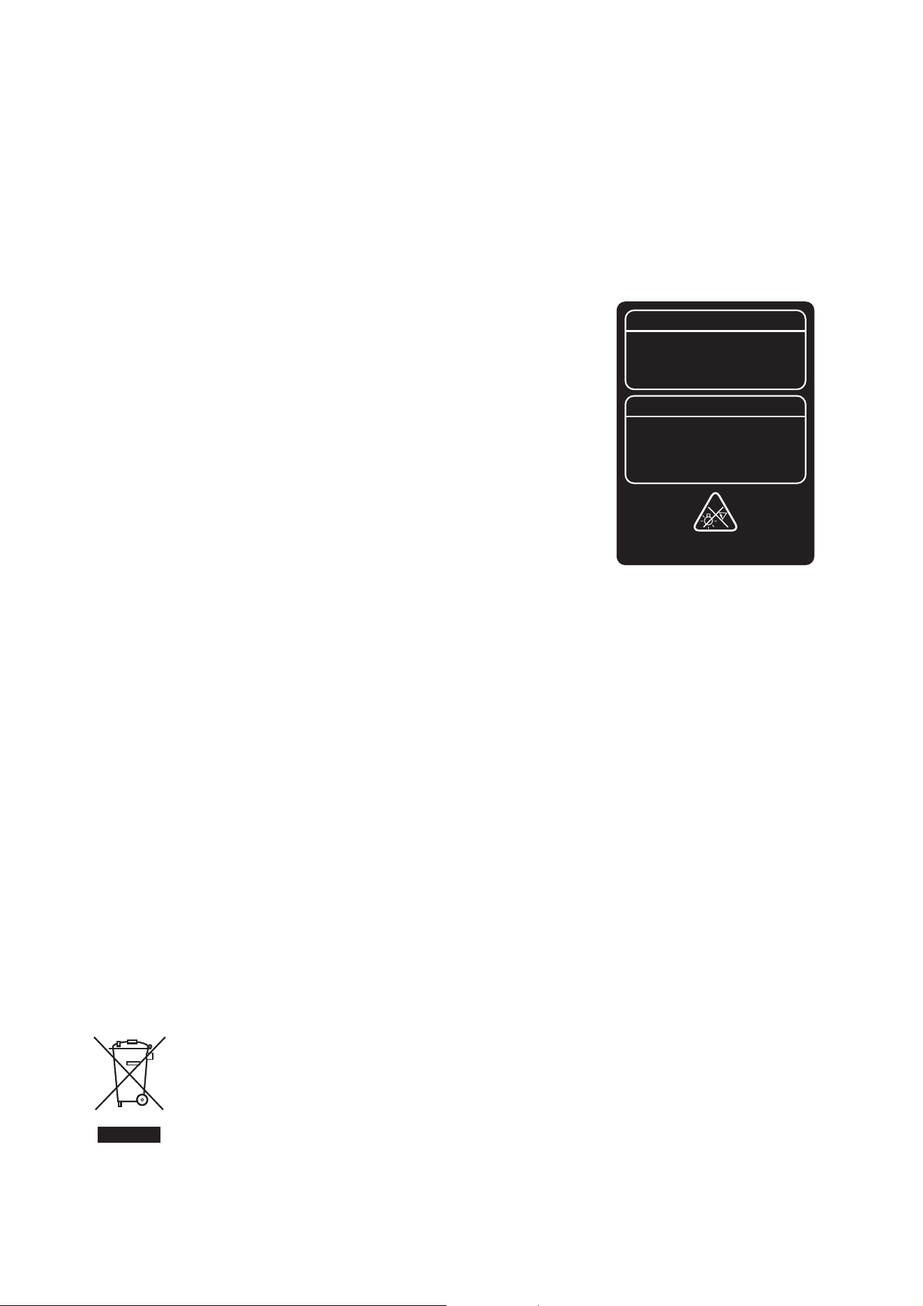
Photobiological Safety Warning
The label shown on the right is displayed on this product. If it becomes difficult or impossible
to read, it must be replaced using the illustration on the right to reproduce a new label.
FCC Compliance
This equipment has been tested and found to comply with the limits for a Class A digital
device, pursuant to part 15 of the FCC Rules. These limits are designed to provide
reasonable protection against harmful interference when the equipment is operated in a
commercial environment. This equipment generates, uses and can radiate radio frequency
energy and, if not installed and used in accordance with the instructions, may cause harmful
interference to radio communications. Operation of this equipment in a residential area is
likely to cause harmful interference, in which case the user will be required to correct the
interference at his own expense.
Supplier’s Declaration of Conformity
Harman Professional, Inc. have issued an FCC Supplier’s Declaration of Conformity for this
product. The Declaration of Conformity is available for download from the MAC Allure Profile
area of the Martin website at www.martin.com
Canadian Interference-Causing Equipment Regulations - Règlement sur le Matériel Brouilleur du Canada
This Class A digital apparatus meets all requirements of the Canadian Interference-Causing Equipment Regulations.
Cet appareil numérique de la classe A respecte toutes les exigences du Règlement sur le Matériel Brouilleur du Canada.
CAN ICES-003 (A) / NMB-003 (A); CAN ICES-005 (A) / NMB-005 (A)
EU Declaration of Conformity
An EU Declaration of Conformity covering this product is available for download from the MAC Allure Profile area of the Martin website at
www.martin.com.
Hibernation Mode
’Hibernation mode’ is intended as an option to reduce the consequences of having a product fully operational in dirty environments or in
situations where noise level is crucial such as during live performances. The small reduction in energy consumption in Hibernation Mode
is only a subordinate effect.
Intellectual Property Rights
Martin® MAC Allure™ products are covered by one or more of these patents:
CN101430080; CN102713425; CNZL200810128720.0; CNZL200810128776.6; CNZL200810144668.8; CNZL201080025103.3;
CNZL201180014884.0; CNZL201380004370.6; CZ17567; EP2058586; EP2113714; EP2117284; EP2136136; EP2326150;
EP2443381; EP2536974; EP2550686; EP2828577; EP2881650; US6971770; US7,703,948; US7,789,543; US7,905,630;
US7,942,535; US7,990,673; US7222997; US7498756; US8,449,141; US8,708,535; US8,770,762; US9217551; US9217559;
and/or one or more of these patent applications:
CN104696882; CN104698579; CN104976548; CN105402641; CN201410740291.8; CN201410742572; DKPA201700088;
EP17167067.2; EP2091302; EP2881651; EP2881652; EP2881653; EP2927579; EP2995852; US2015/0285483; US20150159827;
US20150159828; US20150159830; US20160069540; US20160102850;
and/or one or more other intellectual property rights, including one or more intellectual property rights listed on www.martin.com/ipr
Disposing of this product
Martin products are supplied in compliance with Directive 2012/19/EC of the European Parliament and of the Council
of the European Union on WEEE (Waste Electrical and Electronic Equipment), where applicable.
Help preserve the environment! Ensure that this product is recycled at the end of its life. Your supplier can give details
of local arrangements for the disposal of Martin products.
This product contains a lithium battery. Ensure that it is disposed of correctly and responsibly by an authorized
recycling or waste disposal center at the end of its life. Where applicable, Martin participates in schemes whose aim is
to ensure that local recycling and/or waste disposal centers accept batteries from Martin products.
SAFETY CABLE
WARNING - Possibly hazardous optical
radiation emitted from this product.
Do not look at operating lamp.
Eye injury may result.
RISK GROUP 3
AVERTISSEMENT - Produit à
émission de radiations visibles
potentiellement dangereuses. Ne pas
regarder le faisceau en fonctionnement.
Risque de lésions oculaires.
GROUPE DE RISQUE 3


www.martin.com