
WELDING CUTTING TORCH KIT VICTOR TYPE
SAVE THIS MANUAL: KEEP THIS MANUAL FOR SAFETY WARNINGS, PRECAUTIONS, ASSEMBLY,
OPERATING, INSPECTION, MAINTENANCE AND CLEANING PROCEDURES. WRITE THE PRODUCT’S
SERIAL NUMBER ON THE BACK OF THE MANUAL NEAR THE ASSEMBLY DIAGRAM (OR MONTH
AND YEAR OF PURCHASE IF PRODUCT HAS NO NUMBER).
OWNER’S MANUAL AND SAFETY INSTRUCTIONS
ITEM: 55146
FOR QUESTIONS PLEASE CALL OUR CUSTOMER SUPPORT: (909) 628 4900 MON-FRI 9AM TO 3PM PST

IMPORTANT SAFETY INFORMATION
GENERAL SAFETY WARNINGS
Read all safety warnings and instructions. Failure to follow the warnings and instructions may
result in electric shock, re and/or serious injury. Save all warnings and instructions for future
reference.
SAFETY
The warnings, precautions, and instructions discussed in this instruction manual cannot cover all possible
conditions and situations that may occur. It must be understood by the operator that common sense and
caution are factors which cannot be built into this product, but must be supplied by the operator. Read
carefully and understand all ASSEMBLY AND OPERATION INSTRUCTIONS before operating. Failure to
follow the safety rules and other basic safety precautions may result in serious personal injury.
Stay alert, watch what you are doing, and use common sense when operating the tool. DO NOT use the
tool while you are tired or under the inuence of drugs, alcohol, or medication.
Dress properly. DO NOT wear loose clothing, dangling objects, or jewellery. Keep your hair, clothing
and gloves away from moving parts. Loose clothes, jewellery, or long hair can be caught in moving parts.
Wear the proper personal protective equipment when necessary. Use ANSI Z87.1 compliant safety
goggles (not safety glasses) with side shields, or when needed, a face shield. Use a dust mask in dusty
work conditions.
DO NOT overreach. Keep proper footing and balance at all times.
1
Read and understand all instructions. Failure to follow all instructions may result in serious injury or
property damage.
DO NOT allow persons to operate or assemble the product until they have read this manual and have
developed a thorough understanding of how it works.
DO NOT modify this product in any way. Unauthorized modication may impair the function and/or
safety and could affect the life of the product. There are specic applications for which the product
was designed.
Inspect the work area before each use. Keep work area clean, dry, free of clutter, and well lit. Cluttered,
wet, or dark work areas can result in injury. Using the product in conned work areas may put you
dangerously close to cutting tools and rotating parts.
DO NOT use the product where there is a risk of causing a re or an explosion; e.g., in the
presence of ammable liquids, gases, or dust. The product can create sparks, which may ignite the
ammable liquids, gases, or dust.
DO NOT allow the product to come into contact with an electrical source. The tool is not insulated
and contact will cause electrical shock.
Keep children and bystanders away from the work area while operating the tool. DO NOT allow
children to handle the product.
Be aware of all power lines, electrical circuits, water pipes, and other mechanical hazards in
your work area. Some of these hazards may be hidden from your view and may cause personal injury
and/or property damage if contacted.

Remove keys or wrenches before connecting the tool to an air supply, power supply, or turning on the tool.
A wrench or key that is left attached to a rotating part of the tool may cause personal injury.
2
Check for damaged parts before each use. Carefully check that the product will operate properly and
perform its intended function. Replace damaged or worn parts immediately. Never operate the
product with a damaged part.
DO NOT use a product with a malfunctioning switch. Any power tool that cannot be controlled with
the power switch is dangerous and must be repaired by an authorized service representative
before using.
Disconnect the power/air supply from the product and place the switch in the locked or off position
before making any adjustments, changing accessories, or storing the tool. Such preventive safety
measures reduce the risk of starting the tool accidentally.
IMPORTANT SAFETY INFORMATION
When possible, move the work to a location well away from combustible materials. If relocation is NOT
possible, protect the combustibles with a cover made of re resistant material. Remove or make safe all
combustible materials for a radius of 35 feet (10 meters) around the work area.
Enclose the work area with portable re resistant screens. Use a re resistant material to block all openings
and protect combustible walls, ceilings, oors, etc.
If working near/on a metal wall, ceiling, oor, etc., prevent ignition of combustibles on the other side by
moving the combustibles to a safe location. If relocation of combustibles is NOT possible, designate
someone to act as a re watch equipped with a re extinguisher during the welding or cutting process and
for at least one half hour after the welding or cutting project is completed.
DO NOT place the Torch on any material other than bare concrete until it has cooled completely.
DO NOT weld or cut any material that has a combustible coating or a combustible internal structure, such
as drums or tanks, without an approved method for eliminating the hazard.
DO NOT dispose of hot slag in containers holding combustible materials.
Keep a fully charged re extinguisher close by and know the proper way to use it.
After welding or cutting make a thorough check for evidence of re and be aware the easily visible ame
or smoke may not be present for some time after a re has started.
Clean and purge containers before applying heat. DO NOT apply heat to a container that has held an
unknown substance or a combustible material whose contents, when heated, can produce ammable or
explosive vapors. Vent closed containers, including castings, before preheating, cutting, or welding.
INHALATION HAZARD: Welding and Cutting Produce TOXIC FUMES. Exposure to welding or cutting
exhaust fumes can increase the risk of developing certain cancers, such as cancer of the larynx and lung
cancer. Also, some diseases that may be linked to exposure to welding or cutting exhaust fumes are: Early
onset of Parkinson’s Disease • Heart disease • Ulcers • Damage to the reproductive organs • Inammation
of the small intestine or stomach • Kidney damage • Respiratory diseases such as emphysema, bronchitis,
or pneumonia Use natural or forced air ventilation and wear a respirator approved by NIOSH to protect
against the fumes produced to reduce the risk of developing the above illnesses.
WARNING: This product, when used for welding, plasma cutting, soldering, or similar applications,
produces chemicals known to the State of California to cause cancer and birth defects or other reproductive
harm. (California Health & Safety Code § 25249.5, et seq.)
WARNING: The brass components of this product contain lead, a chemical known to the State of California
to cause cancer and birth defects or other reproductive harm. (California Health & Safety Code § 25249.5,
et seq.)

3
Make sure you are prepared to begin work before opening gas supply.
Always use reverse-ow on the torch and regulator. This greatly reduces the possibility of mixing gases
in the regulator or hose.
Use with oxygen and acetylene only. DO NOT modify this torch or use it for a purpose for which it is not
intended.
Set Acetylene Regulator no greater than 15 PSI. Acetylene is unstable and can explode if over-pressurized.
DO NOT use oil, grease or thread seal tape on any connector.
Use clamps (not included) or other practical ways to secure and support the work piece to a stable
platform. Holding the work by hand or against your body is unstable and may lead to loss of control, re
and/or personal injury.
Use only accessories that are recommended by the manufacturer for your model Torch. Accessories that
may be suitable for one Torch may become hazardous when used on another Torch. Only use proper
gas hoses.
Proper cylinder care. Secure cylinders to a cart, wall or post to prevent them from falling. All cylinders
should be used and stored in an upright position. Never drop or strike a cylinder. Cylinder caps should
be used when moving or storing cylinders. Empty cylinders should be kept in specied areas and marked
“empty”
Never use oil or grease on any inlet connector, outlet connector or cylinder valves. Keep regulators free
of gas and oil.
There must be TWO O-rings on the cone end. The absence of either O-ring can lead to ashback within
the torch handle or cutting attachment.
DO NOT store cylinders in temperatures 120° F or higher.
KEEP WRENCH ON ACETYLENE CYLINDER’S VALVE whenever cylinder is in use to allow quick shut
off in case of emergency.
DO NOT USE FLAME TO DETECT LEAKS.
INSPECT BEFORE EVERY USE. Look for the following, and do not use kit if any damage is noted:
A. Inspect the tapered seating surfaces on the Nozzles and the Tip Nut. Have a qualied technician
resurface the seat area if it has dents, burrs, or is burned. A poor seating surface may result in backre
or ashback.
B. Examine all hoses for cuts, cracks, burns, worn areas, or other damage. DO NOT use if damaged.
C. Check for loose connections using soapy water solution. Tighten or repair any leaks found.
D. DO NOT use the Torch Kit if either gas does not turn off completely when the Oxygen Torch Valve and
Acetylene Torch Valve are closed. Leakage of gas from the tip is a substantial safety risk. If gas cannot
be turned off at the Torch Handle, it is dangerous and must be replaced.
E. Inspect for any other defects or damage. Do not use any damaged parts. Tag damaged parts “Do not
use” until repaired.
Backre and Flashback: When the ame goes out with a loud “pop” it is called a backre. Backre can
be caused by A. Operating the torch at low pressures required for the toll tips used. B. Touching the
tip against the work piece. C. Overheating the tip or abstraction in the tip. If backre occur, shut off the
torch handle valves, oxygen rst, and after remedying the cause, relight the torch. If ashback occurs,
close the torch handle valves immediately. Flashback generally indicates a problem that needs repaired.
A clogged tip, improper functioning in the valves or incorrect oxygen pressure. Make sure to nd and x
the cause before lighting the torch.
IMPORTANT SAFETY INFORMATION
4
ASSEMBLY AND OPERATING INSTRUCTIONS
1. Secure cylinders to a cart, wall or post to prevent them from falling. DO NOT place an Acetylene cylinder
on its side.
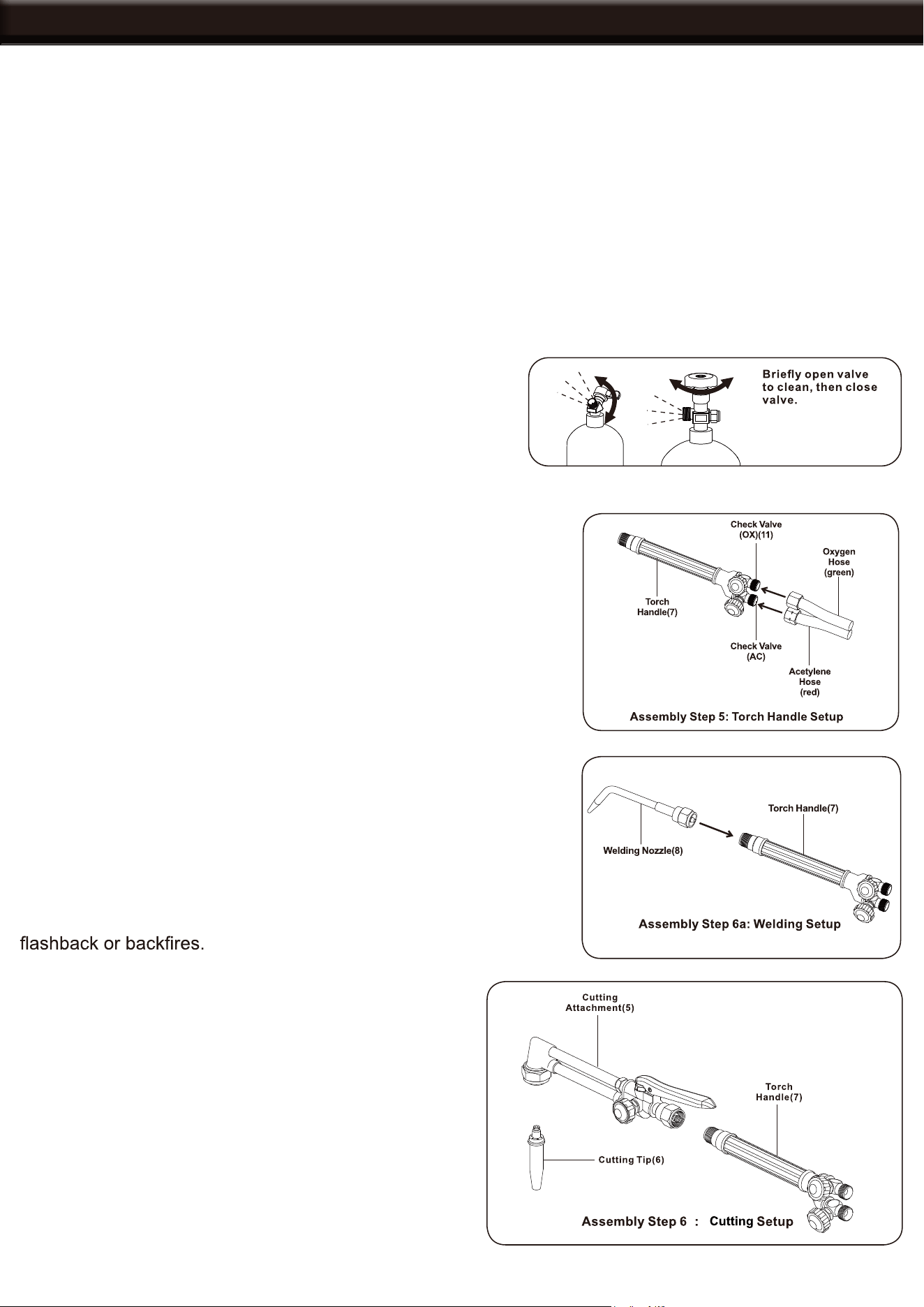
2. While standing to one side “crack” each cylinder valve. “Cracking” is to simply open and close the valve,
allowing a small amount of gas to escape and to clear the valve of any foreign material.
WARNING: TO PREVENT FIRE AND EXPLOSION: Make sure there is no oil or grease, or ignition
source nearby before proceeding with the next step.
WARNING: KEEP A WRENCH ON THE ACETYLENE VALVE whenever cylinder is in use to allow for
quick shut off in case of emergency.
3. Attach the green labeled Oxygen Regulator (9) to the
Oxygen Cylinder (13) and the green Oxygen Hose to
the Regulator.
4. Attach the red labeled Acetylene Regulator (10) to
the Acetylene Cylinder (14) and the red Acetylene hose
to the regulator. Tighten counter-clockwise, threads are
reversed.
TOOL SET UP 1 OF 3
5. To set up the Torch Handle (7): A. Remove the plastic inlet covers.
B. Make sure both check valves are in place on the torch handle. C.
Connect the green Oxygen Hose to the Oxygen check valve
and the Torch Handle. D. Connect the red Acetylene hose to the
Acetylene check valve on the torch handle. Tighten counter-
clockwise, threads are reversed.
6A. Connect the welding nozzle (8) to the torch handle.
6B. WARNING: BEFORE CONNECTING, make sure the two
O-Rings on the end of the cutting attachment (5) are not damaged
or missing, gases will mix inside the Torch Handle and result in
Connect the Cutting Attachment (5) to the Torch
Handle. Then connect the Cutting Tip (6) to the Cutting
Attachment.
7. Before operation, perform “leak tests” must be done
after connection to check for leaks in the system. See
the following pages for more information.
b
5
CHECKING FOR LEAKS
TOOL SET UP 2 OF 3: Detecting Major Leaks
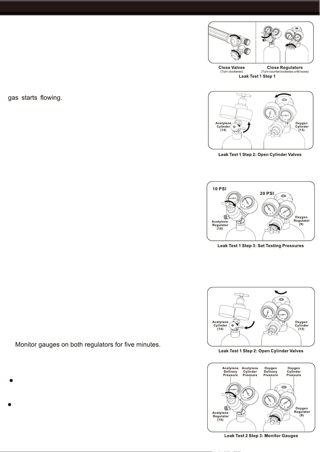
1. After everything is connected, close both Torch Handle Valves,
turning clockwise. Close regulators, turning knobs counter-
clockwise until loosened.
2. Open the cylinder valves turning counter-clockwise only until the
WARNING: Only open Acetylene Cylinder
Valve 1/4 to 1/2 turn.
3. Adjust the Oxygen Regulator to deliver 20 PSIG. Adjust the
Acetylene Regulator to deliver 10 PSIG. DO NOT EXCEED 15 PSI
ACETYLENE PRESSURE.
WARNING: KEEP WRENCH ON ACETYLENE VALVE whenever
the cylinder is in use to allow shut off in case of an emergency.
4. Check all connections for leaks using soapy water. If leaks are
found, tighten connections. If a leak persists, discontinue use and
call a gas supplier. If no leaks are found with this test, move on to
the gauge monitoring test.
TOOL SET UP 3 OF 3: Gauge Monitoring Leak Test
1. Follow all steps from the “soapy water test” above to prepare
the gauge monitoring test.
2. Close both cylinder valves by turning clockwise.
3.
If the readings do not change, the test is completed and the
system has no leaks.
If the readings do change, there is a leak on that side of the
system. Follow the Gauge Leak Analysis on the next page to
diagnose.
6
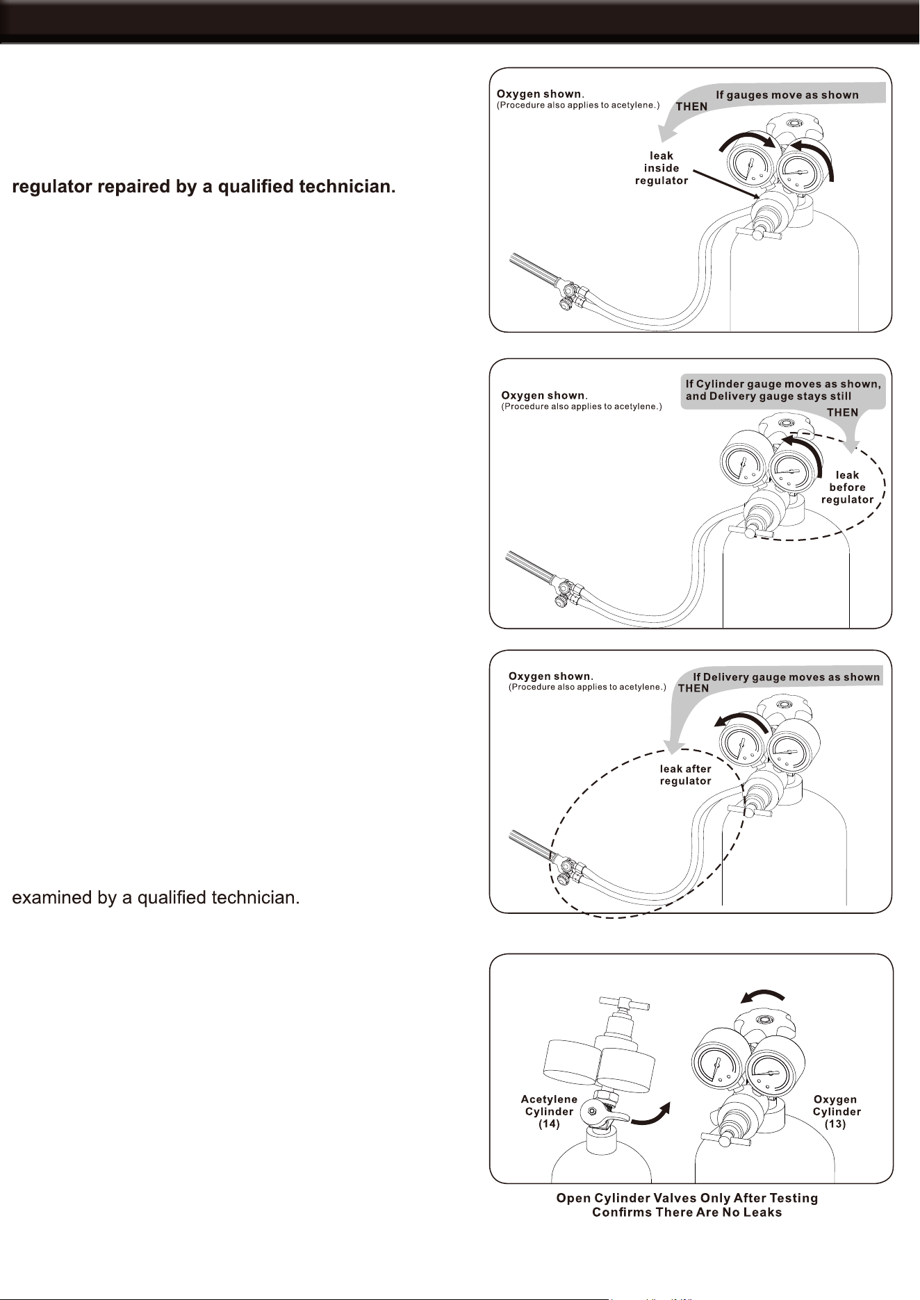
GAUGE LEAK ANALYSIS
If the Cylinder pressure decreases and the delivery
pressure increases, there is a leak in the regulator
seat.
There is a leak in the regulator seat. Have the
If the Cylinder pressure decreases but the delivery
pressure remains constant, the leak is at the cylinder
valve or connection between regulator and cylinder
valve.
DANGER: To prevent serious injury and DEATH, DO
NOT tighten or adjust any connection between the
cylinder and the cylinder valve. If the cylinder valve
is leaking, move the cylinder outside and call your
gas company immediately.
1. Release pressure from the system.
2. Tighten the connection between the regulator and the
cylinder valve.
3. Repeat the Gauge Leak Test.
2. Tighten the connection between the regulator and the
cylinder valve.
If the delivery pressure decreases, the leak is at the
regulator outlet connection, within the hose, at the torch
inlet connection or at the torch valve on the torch handle.
1. Release pressure from the system.
3. Tighten the torch handle inlet connection.
2. Tighten the regulator outlet connection.
4. Repeat the Gauge Leak Test. If the gauges do not
change, the test is completed and the system has
no leaks. If the connections are still leaking, have it
No Leaks Found
If the leak testing has been completed and the unit is
found to be working properly, open the cylinder valves,
turning counter-clockwise and proceed to operation.
WARNING: Only open Acetylene Cylinder Valve 1/4
to 1/2 turn to allow quick shut off.
WARNING: KEEP WRENCH ON ACETYLENE VALVE
whenever the cylinder is in use to allow shut off in
case of an emergency.
7
OPERATION
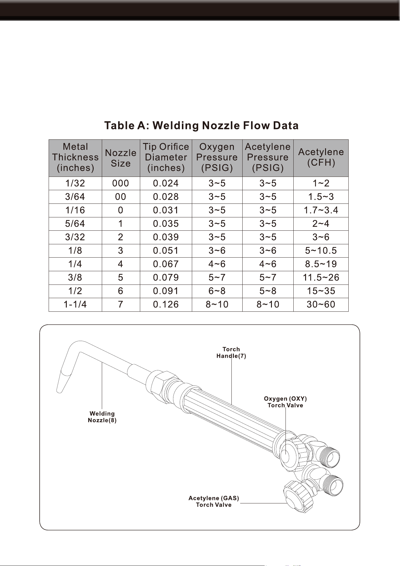
This torch handle is capable of welding metals from 1/32” up to 1/1/4” thick. The included welding nozzle, size
0, will weld metals up to 1/16” thick. Check the thickness of the metals to be welded and use the chart below
to choose the size nozzle for the job. If welding metals other than 1/32” to 1/16” thick, a different welding
nozzle will be needed.
Welding Tip Pressure Settings
NOTE: Welding the thicker metals noted below will require special techniques, such as edge chamfering,
that are outside the scope of this manual.
8
OPERATION
Welding instructions
1. Set up welding according to instructions on pages
6-9.
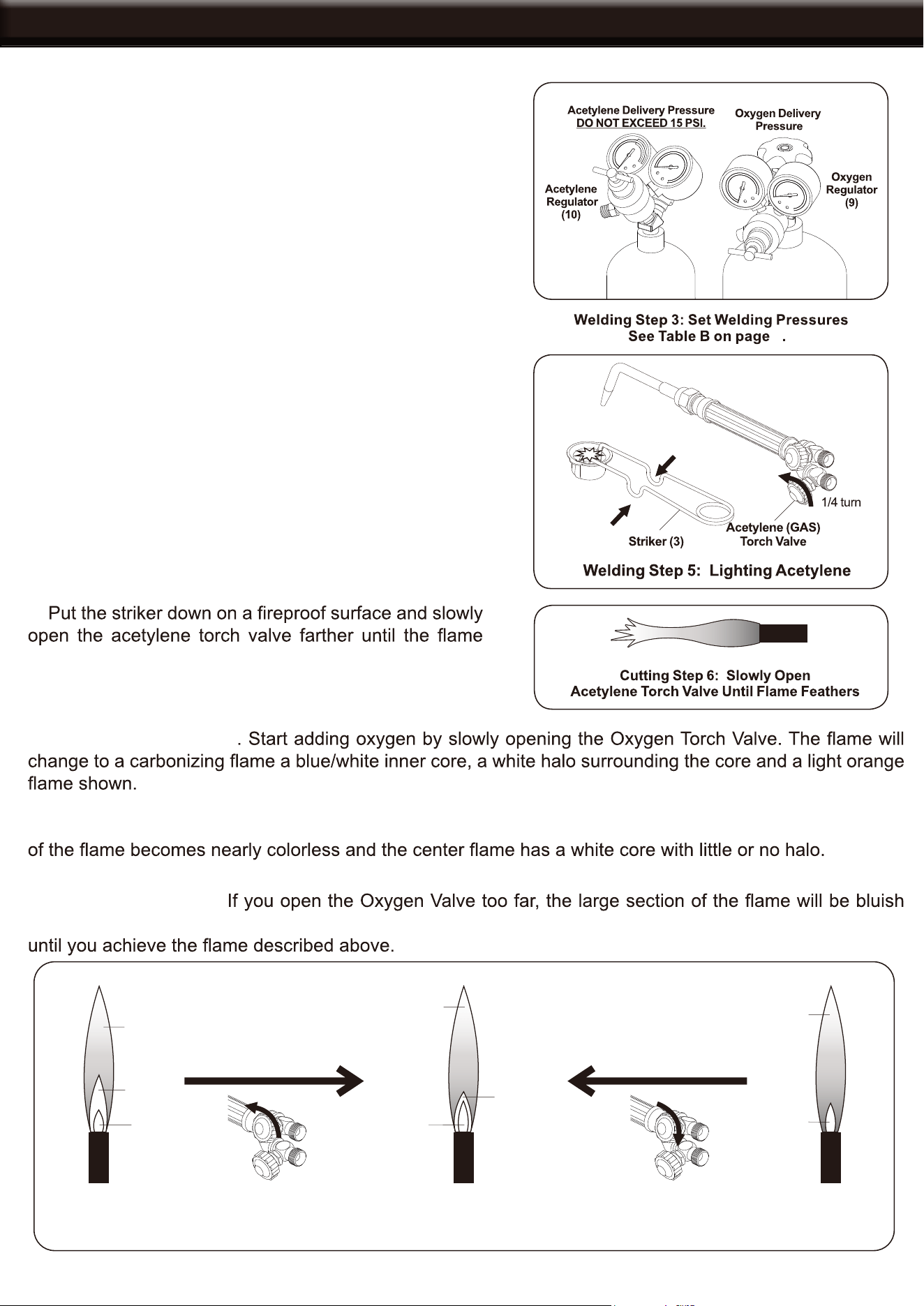
3. Adjust the Acetylene and Oxygen regulators to
their proper working pressures, see table A on the
previous page. DO NOT EXCEED 15PSI ACETYLENE
PRESSURE.
2. Close both valves on the Torch Handle securely.
4. Hold the Torch Handle in one hand and the striker in
the other hand.
5. Open the Acetylene Torch valve about a 1/4 turn
and quickly ignite the gas coming out of the nozzle by
squeezing the handle of the striker, creating a spark.
WARNING: DO NOT use matches or a butane lighter
to light the torch.
6.
feathers at its edges slightly as shown.
7. Flame Adjustment: A
B. Proper Oxygen Mix: Continue slowly opening the Oxygen Torch Valve until the large light orange section
C. Too Much Oxygen:
orange and the inner core will be small as shown in welding step 7. Close the Oxygen Torch valve slightly
7
Light
Orange
Flame
White
Acetylene
Halo
Bluish
Core
Open Oxygen Torch
Valve Slightly
Nearly
Colorless
Flame
Blue-White
Core
Little or
No Halo
Close Oxygen Torch
Valve Slightly
Bluish
Orange
Flame
Small, Less
Bright Core
a. Starting to Add Oxygen b. Proper Oxygen Mix c. Too Much Oxygen
Welding Step 7: Welding Flame Adjustment
9
OPERATION
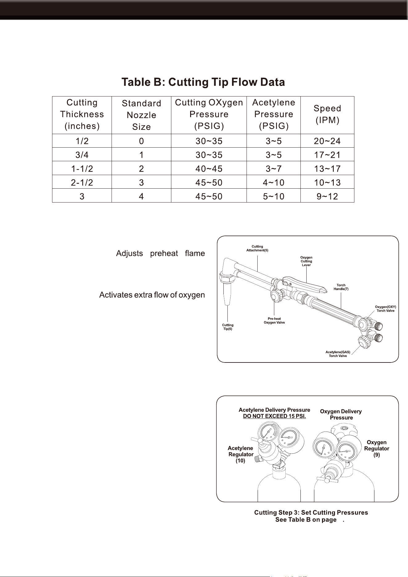
Cutting Tip Pressure Settings
The Cutting Attachment is used to cut metal up to 3” thick. This included tip size 0, cuts metal up to 1/2”
thick. Check the thickness of the metal to be cut and use the chart below to choose the appropriate size tip
for the job. If cutting metals over 1/2” thick, a different tip will be needed.
The Cutting Attachment is attached to the Torch Handle and a Cutting Tip is attached to the end of the
cutting attachment.
Preheat Oxygen Valve
oxygen level.
Oxygen Cutting Lever
for cutting.
Cutting Instructions
1. Set up for cutting according to instructions on 6-9.
2. Close all valves on the Torch handle and Cutting
Attachment securely.
3. Adjust the Acetylene and Oxygen regulators to
their proper working pressures. See Table B. DO NOT
EXCEED 15 PSI ACETYLENE PRESSURE.
4. Hold the Torch Handle in one hand and the striker in
the other hand.
9
10
OPERATION
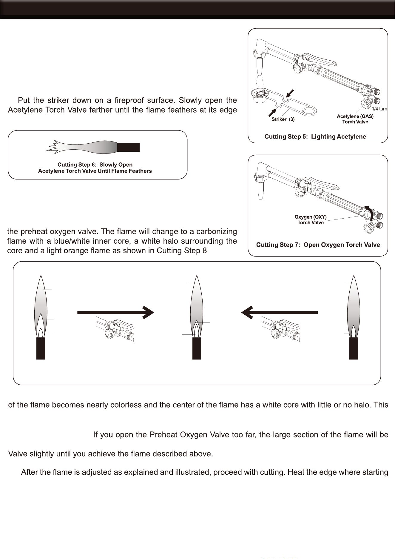
5. Open the Acetylene Torch Valve about 1/4 turn and quickly
ignite the Acetylene gas coming out of the nozzle by squeezing
the nozzle by squeezing the handle of the striker, creating a spark.
WARNING: DO NOT use matches or a butane lighter to light
the torch.
6.
slightly.
7. DO NOT SQUEEZE THE OXYGEN CUTTING LEVER. Open
the oxygen Torch Valve.
8. Flame Adjustment: A. Starting to add Oxygen: Slowly open
B. Proper Oxygen Mix: Continue slowly turning the Preheat Oxygen Valve until the large light orange section
is the NEUTRAL FLAME needed for operation as shown in Cutting Step 8 Illustration, center.
C. Too Much Oxygen:
bluish orange and the inner core will be small as shown in Cutting step 8 right side. Close the Preheat Oxygen
9a.
the cut until it is red hot.
WARNING: Start the cut at the edge of the workpiece.
9b. After preheating, press the Oxygen Cutting Lever and slowly guide the torch along the cut line to cut the
metal. After cutting, follow the shut down instructions on the following page.
Light
Orange
Flame
White
Acetylene
Halo
Bluish
Core
Open Pre-heat
Oxygen Valve Slightly
Nearly
Colorless
Flame
Blue-White
Core
Little or
No Halo
Close Pre-heat
Oxygen Valve Slightly
Bluish
Orange
Flame
Small, Less
Bright Core
a. Starting to Add Oxygen b. Proper Oxygen Mix
c. Too Much Oxygen
Cutting Step 8: Pre-heat Flame Adjustment
11
Welding Shut down Settings
1. After work is complete, close the Oxygen Torch Valve First clockwise, then
close the Acetylene Torch Valve clockwise.
2. Fully close both cylinder valves by turning clockwise.
3. Open the Acetylene Torch Valve counter clockwise to allow
the pressure to bleed out.
4. Open the Oxygen Torch Valve counter clockwise to allow all
the pressure to bleed out.
5. After releasing pressure, turn the Pressure Adjusting Screws
counter clockwise and remove them from the regulators.
IMPORTANT: Failure to do this may permanently damage the
regulators.
SHUTTING DOWN
12
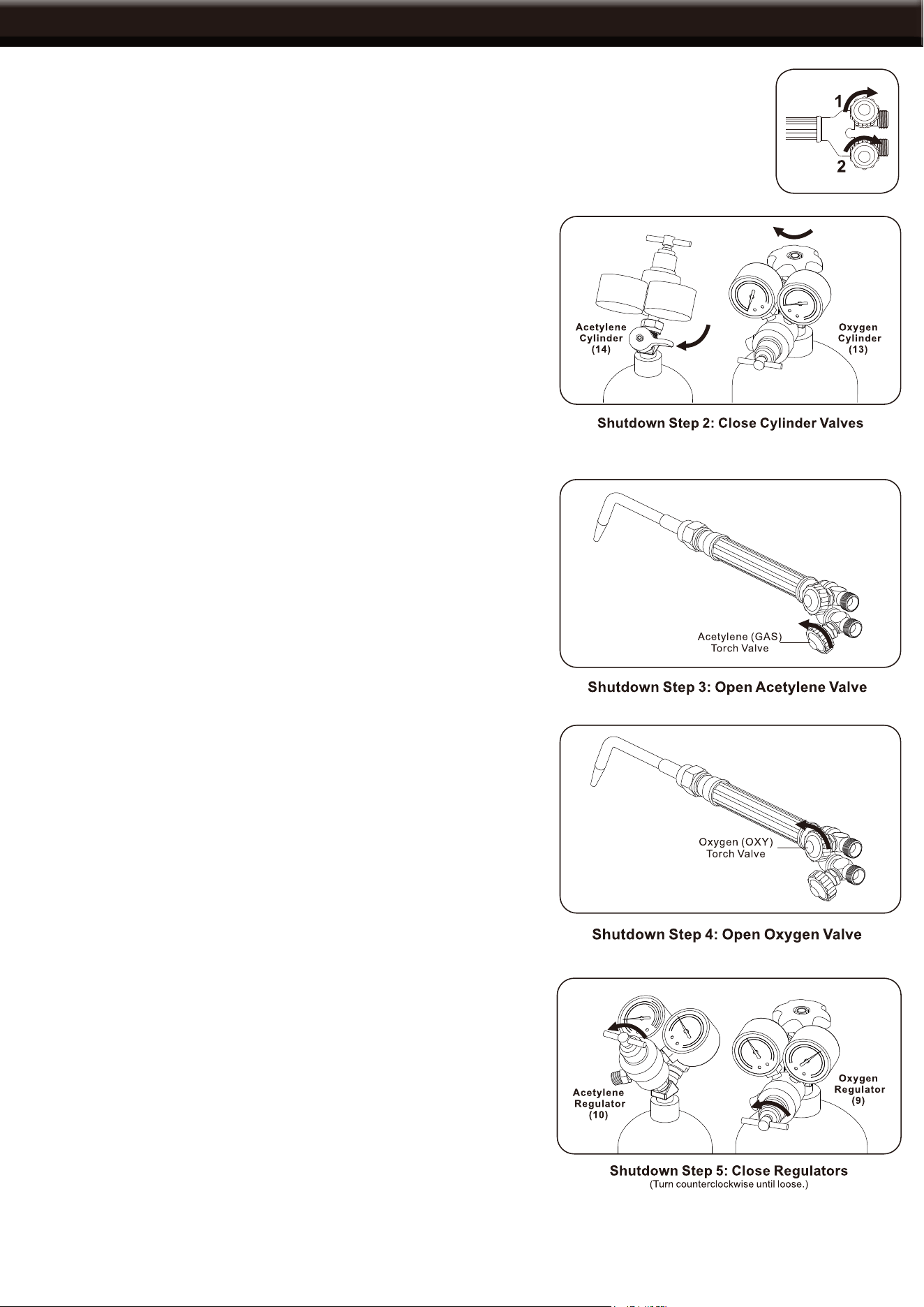
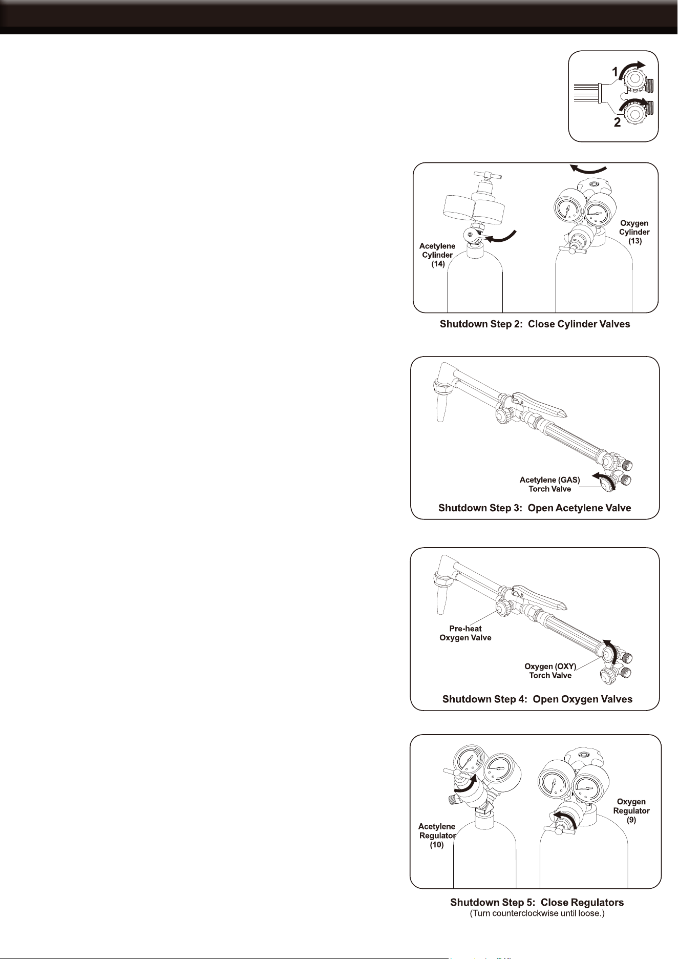
SHUTTING DOWN
Cutting Shut down Settings
1. After work is complete, close the Oxygen Torch Valve First clockwise, then
close the Acetylene Torch Valve clockwise.
2. Fully close both cylinder valves by turning clockwise.
3. Open the Acetylene Torch Valve counter clockwise to allow
the pressure to bleed out.
4. Open the Oxygen Torch Valve counter clockwise and open the
preheat Oxygen Valve counter clockwise to allow all pressure to
bleed out.
5. After releasing pressure, turn the Pressure Adjusting Screws
counter clockwise and remove them from the regulators.
IMPORTANT: Failure to do this may permanently damage the
regulators.
13
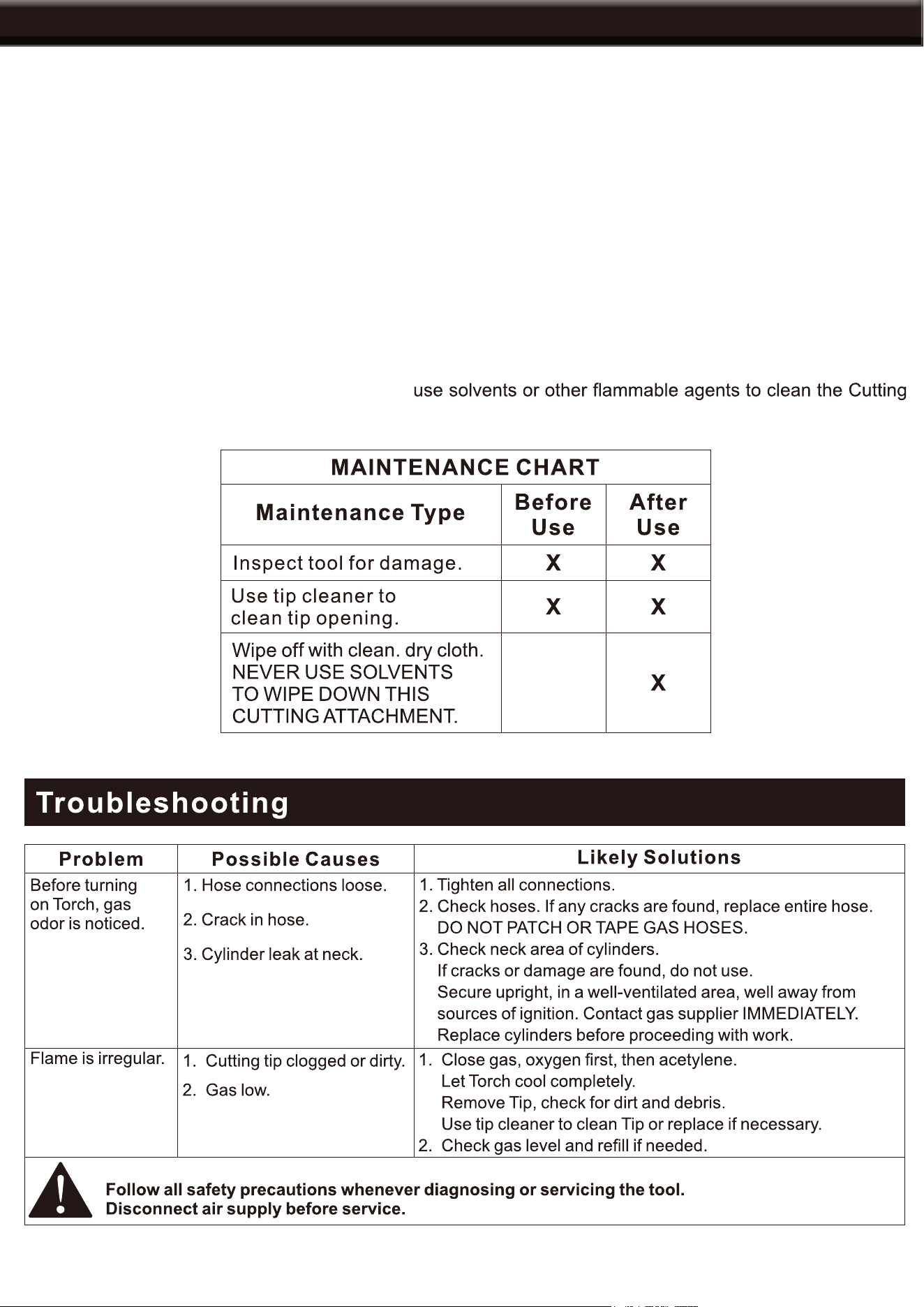
MAINTENANCE / TROUBLESHOOTING
WARNING: To prevent serious injury from accidental operation. Close the oxygen, then acetylene
and allow the torch to cool completely, then disconnect the hoses before performing any inspection,
maintenance or cleaning procedures.
To prevent serious injury from tool failure, DO NOT use damaged equipment. If abnormal noise,
vibration or leaking gas occurs, have the problem corrected before further use.
1. BEFORE EACH USE: inspect the general condition of the Torch Kit. Check for loose hose connections,
cracked or worn hoses and any other condition that may affect its safe operation.
2. Periodically use a tip cleaner to clean out Cutting Tip and Welding Nozzle.
3. To clean the outer body of the Cutting Attachment, use a clean, dry cloth. DO NOT immerse any part of
the Cutting Attachment in ANY liquid. DO NOT
Attachment.
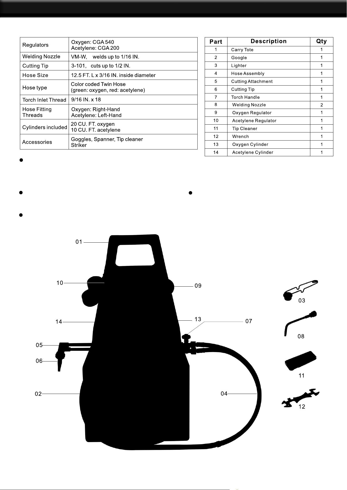
PARTS LIST
PRODUCT SPECIFICATIONS
Capable of welding from 1/32” up to
1-1/4” with the appropriate welding
nozzle.
Capable of cuttiing from 1/2” up to 3”
with the appropriate cutting tip.
Will cut up to 1/2” and weld up to 1/16”
with the included welding and cutting
tips.
Larger welding and cutting tips are sold
seperately.
PARTS LIST
14
15
THE MANUFACTURER AND/OR DISTRIBUTOR HAS PROVIDED THE PARTS LIST AND ASSEMBLY
DIAGRAM IN THIS MANUAL AS A REFERENCE TOOL ONLY. NEITHER THE MANUFACTURER OR
DISTRIBUTOR MAKES ANY REPRESENTATION OR WARRANTY OF ANY KIND TO THE BUYER THAT
HE OR SHE IS QUALIFIED TO MAKE ANY REPAIRS TO THE PRODUCT, OR THAT HE OR SHE IS
QUALIFIED TO REPLACE ANY PARTS OF THE PRODUCT. IN FACT, THE MANUFACTURER AND/OR
DISTRIBUTOR EXPRESSLY STATES THAT ALL REPAIRS AND PARTS REPLACEMENTS SHOULD BE
UNDERTAKEN BY CERTIFIED AND LICENSED TECHNICIANS, AND NOT BY THE BUYER. THE BUYER
ASSUMES ALL RISK AND LIABILITY ARISING OUT OF HIS OR HER REPAIRS TO THE ORIGINAL
PRODUCT OR REPLACEMENT PARTS THERETO, OR ARISING OUT OF HIS OR HER INSTALLATION
OF REPLACEMENT PARTS THERETO.
Record Product’s Serial Number Here:
Note: If product has no serial number, record month and year of purchase instead.
Note: Some parts are listed and shown for illustration purposes only and are not available individually
as replacement parts.
PLEASE READ THE FOLLOWING CAREFULLY
WARRANTY INFORMATION