© 2024 AMETEK SurgeX | Technical Support: 800-645-9721 | surgex.com | B01-00010
User Manual
Switched IP Controllable Surge Protected
PDU
SX-DSP-129 | SX-DSP-169 | SX-DSP-109i | SX-DSP-169i

© 2024 AMETEK SurgeX | Technical Support: 800-645-9721 | surgex.com | B01-00010
2
User Manual

© 2024 AMETEK SurgeX | Technical Support: 800-645-9721 | surgex.com | B01-00010
3
User Manual
Table of Contents
1. Introduction ...................................................................................................................................................................... 5
1.1 Metering is performed at the system level, and includes: ............................................................................................. 5
1.2 Physical Interfaces ........................................................................................................................................................... 5
1.3 Rated & Maximum Current ............................................................................................................................................. 6
1.4 Voltage Requirements ..................................................................................................................................................... 6
2. Installation and Components ............................................................................................................................................ 7
2.1 AC Power: Output ........................................................................................................................................................... 7
2.2 AC Power: Input .............................................................................................................................................................. 7
2.3 Ethernet and Account Admin Password ......................................................................................................................... 7
2.4 USB-Micro AB .................................................................................................................................................................. 7
2.5 LED Indicators: ................................................................................................................................................................ 7
2.6 Buttons ............................................................................................................................................................................ 8
2.6.1 Resettable fuse ......................................................................................................................................................... 8
2.6.2 Hardware Reset ........................................................................................................................................................ 8
2.6.3 Software Reset ......................................................................................................................................................... 8
3. Rack Installation ................................................................................................................................................................ 9
4. Web Server ...................................................................................................................................................................... 11
4.1 Login .............................................................................................................................................................................. 11
4.2 Power Management ...................................................................................................................................................... 11
4.3 Reports .......................................................................................................................................................................... 11
4.4 Setup ............................................................................................................................................................................. 13
4.4.1 Device Setup ........................................................................................................................................................... 14
4.4.2 Network Setup ..................................................................................................................................................... 18
4.4.3 Network Advanced Setup ....................................................................................................................................... 19
4.4.4 Triggers Setup ................................................................................................................................................. 22
4.4.5 Users Setup ..................................................................................................................................................... 27
4.4.6 Sequences Setup ............................................................................................................................................. 27
4.5 Utilities .......................................................................................................................................................................... 28
4.5.1 File Upload ...................................................................................................................................................... 28
4.5.2 Backup/Restore .............................................................................................................................................. 29
4.5.3 Factory Reset .................................................................................................................................................. 29
4.5.4 Soft Reboot ..................................................................................................................................................... 29
5. Security ............................................................................................................................................................................ 30

© 2024 AMETEK SurgeX | Technical Support: 800-645-9721 | surgex.com | B01-00010
4
User Manual
5.1 Authentication .............................................................................................................................................................. 30
5.1.1 802.1X .................................................................................................................................................................... 30
5.1.2 SSO (Single Sign-On) ............................................................................................................................................... 30
5.2 Interfaces ...................................................................................................................................................................... 30
5.2.1 Network Interface .................................................................................................................................................. 30
6. Application Programming Interfaces (APIs) .................................................................................................................... 31
6.1 HTTP/HTTPS REST .................................................................................................................................................. 31
6.2 Interfaces ............................................................................................................................................................... 31
7. Part Numbers .................................................................................................................................................................. 32
7.1 Part Number Scheme ............................................................................................................................................. 32
8. Troubleshooting .............................................................................................................................................................. 33
9. Specifications .................................................................................................................................................................... 34
© 2024 AMETEK SurgeX | Technical Support: 800-645-9721 | surgex.com | B01-00010
5
User Manual
1. Introduction
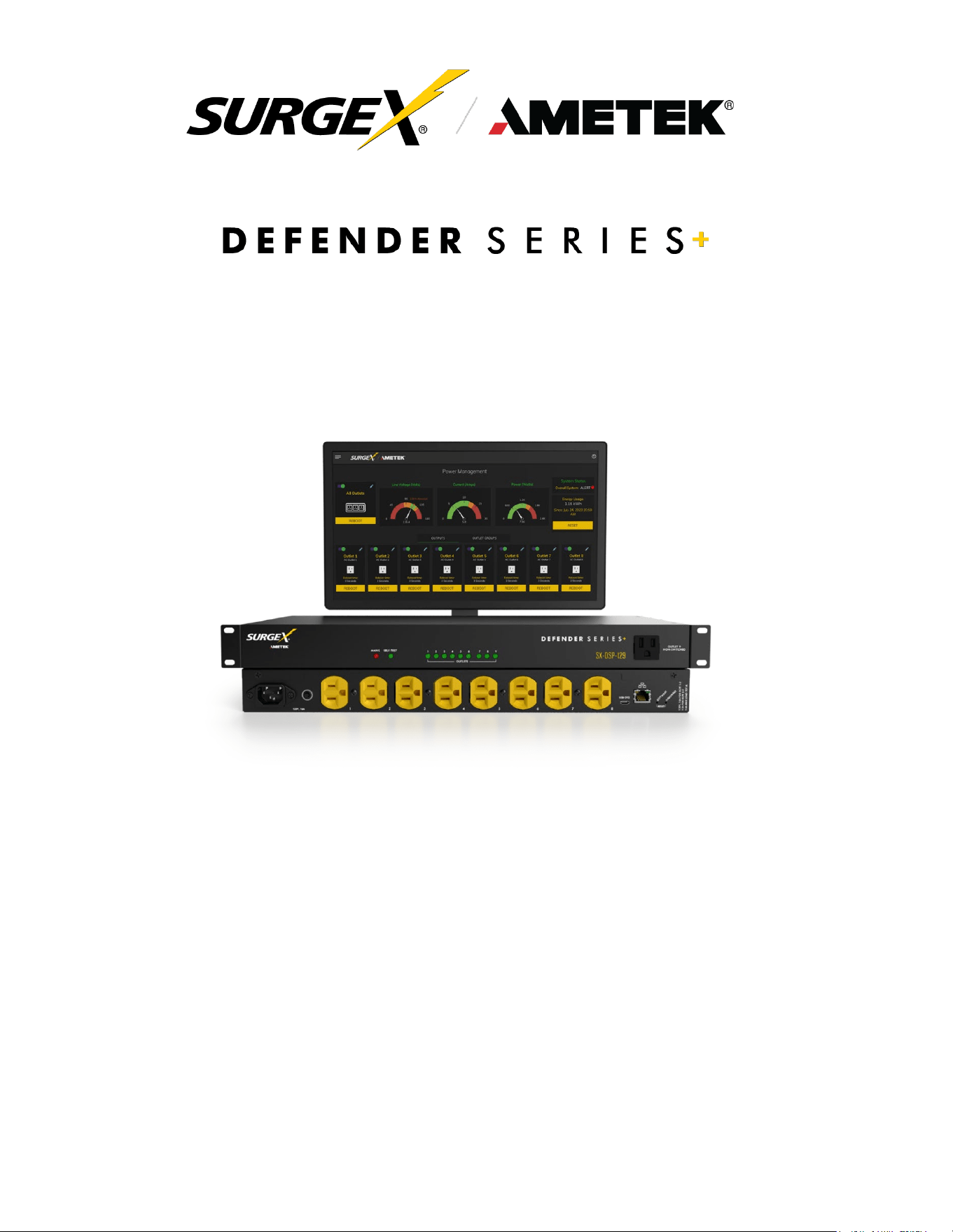
The SurgeX Defender Series+ is an AC power distribution unit with power conditioning, control, and
monitoring, with independently IP switchable AC receptacles and current monitoring for the inlet. Design for
mounting on the rack. The internal web server provides configuration, output control, monitoring, and retrieval
of data logs. Multiple security and communication interface options are supported.
Defender Series+ incorporates SurgeX Multistage surge suppression and EMI/RFI filtering technology. This
protection safeguards the AC outlets.
The extensive programming capabilities of the Defender Series+ provides advanced sequencing and
scheduling operations. Triggers can be programmed to activate on an “if X then do Y, then do Z when no longer
X” basis. Trigger sources include various AC power measurements, scheduling, and AutoPing. Actions include
turning receptacles on and off, cycling a receptacle, executing previously defined sequences, and putting a unit
into shutdown. For example, an action can be created to power cycle a network appliance if it fails to respond to
a series of pings.
1.1 Metering is performed at the system level, and includes:
• Line Voltage
• Neutral-Ground Voltage
• Current
• Power
• Line Frequency
• Power Factor
• Voltage Crest Factor
• Energy
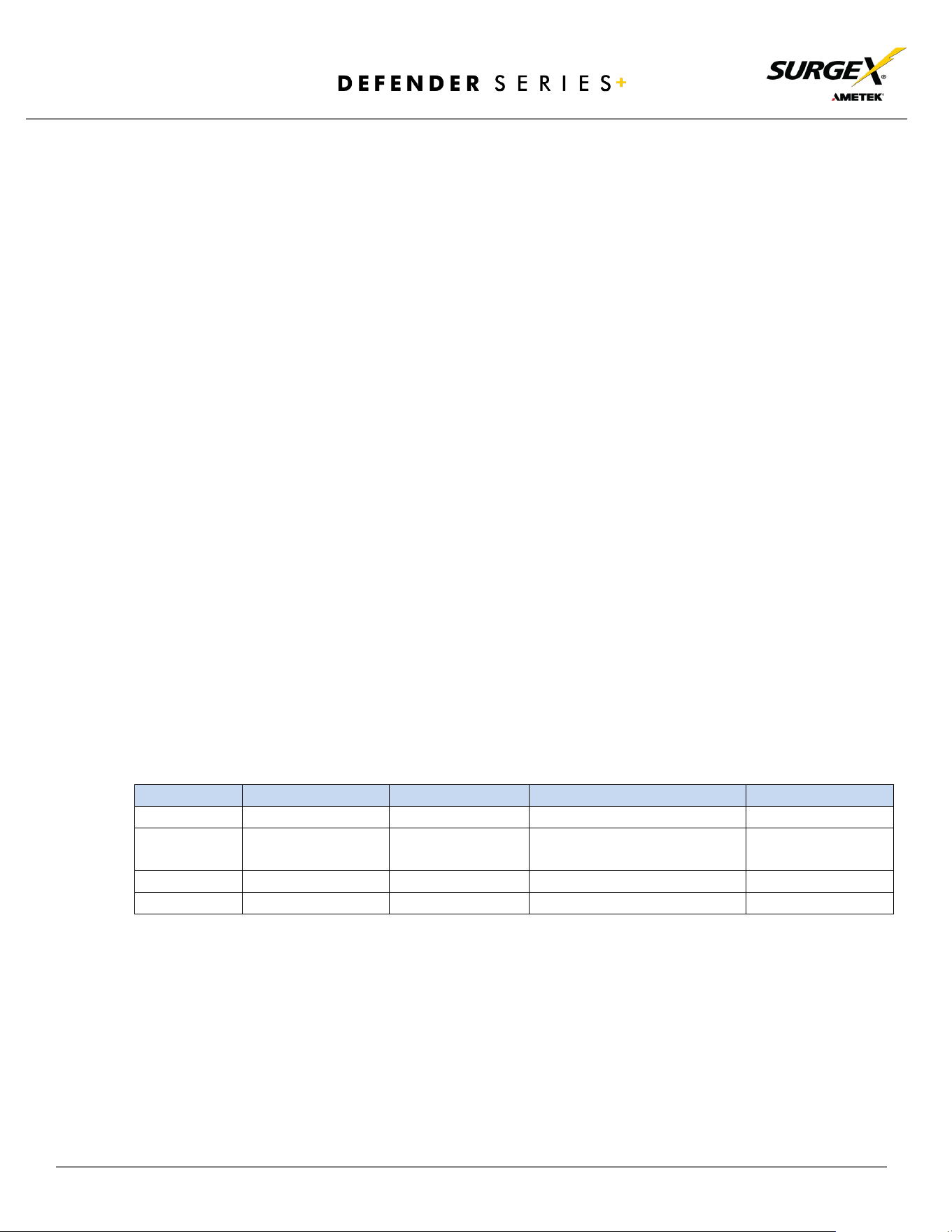
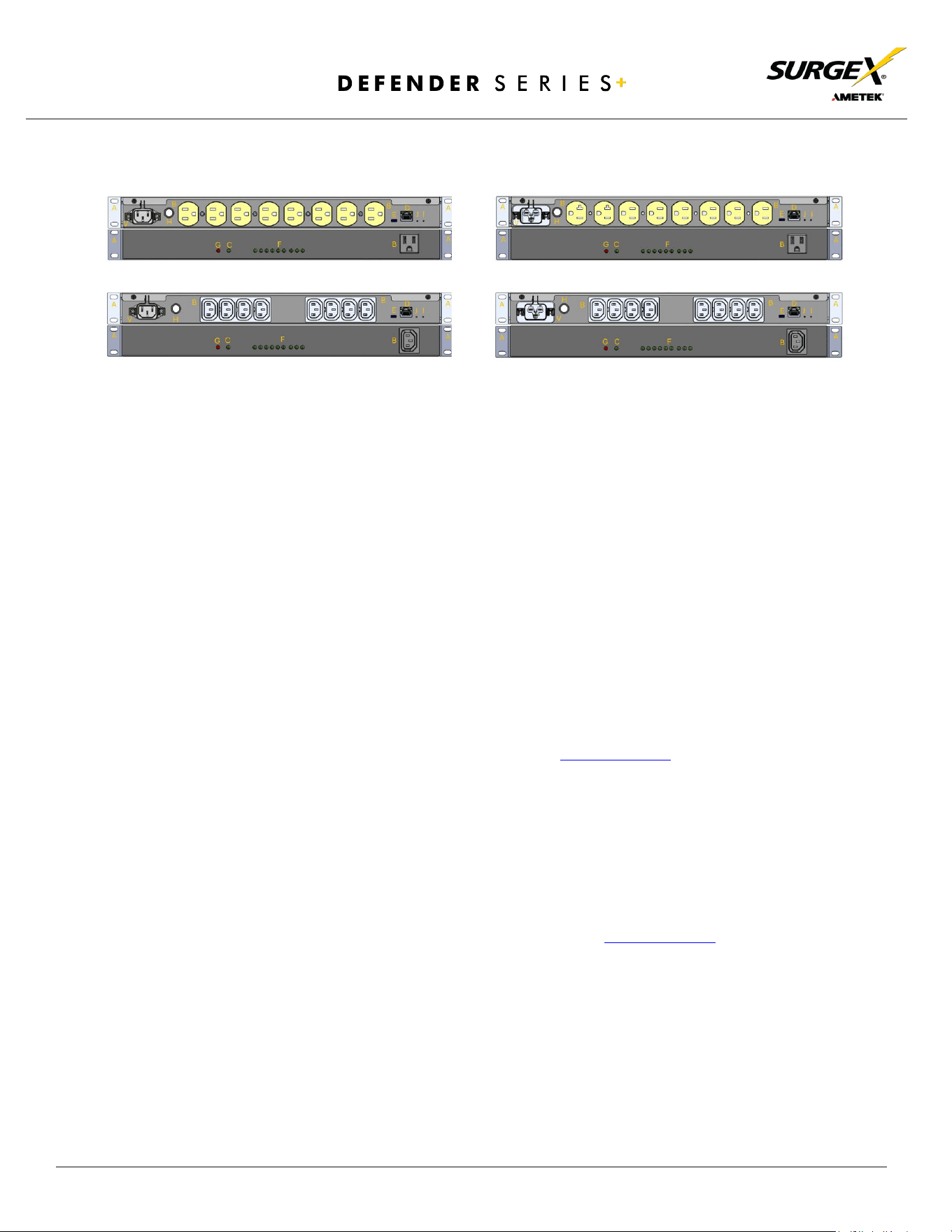
1.2 Physical Interfaces
Model
Output
Input
Communication
Resettable Fuse
SX-DSP-129
(9) NEMA 5-15R
(1) NEMA 5-15P
(1) RJ45, (1) USB-Micro AB
(1) Push Button
SX-DSP-169
(7) NEMA 5-15R,
(2) NEMA 5-20R
(1) NEMA 5-20P
(1) RJ45, (1) USB-Micro AB
(1) Push Button
SX-DSP-109i
(9) IEC 13
(1) IEC C14
(1) RJ45, (1) USB-Micro AB
(1) Push Button
SX-DSP-169i
(9) IEC 13
(1) IEC C20
(1) RJ45, (1) USB-Micro AB
(1) Push Button
© 2024 AMETEK SurgeX | Technical Support: 800-645-9721 | surgex.com | B01-00010
6
User Manual
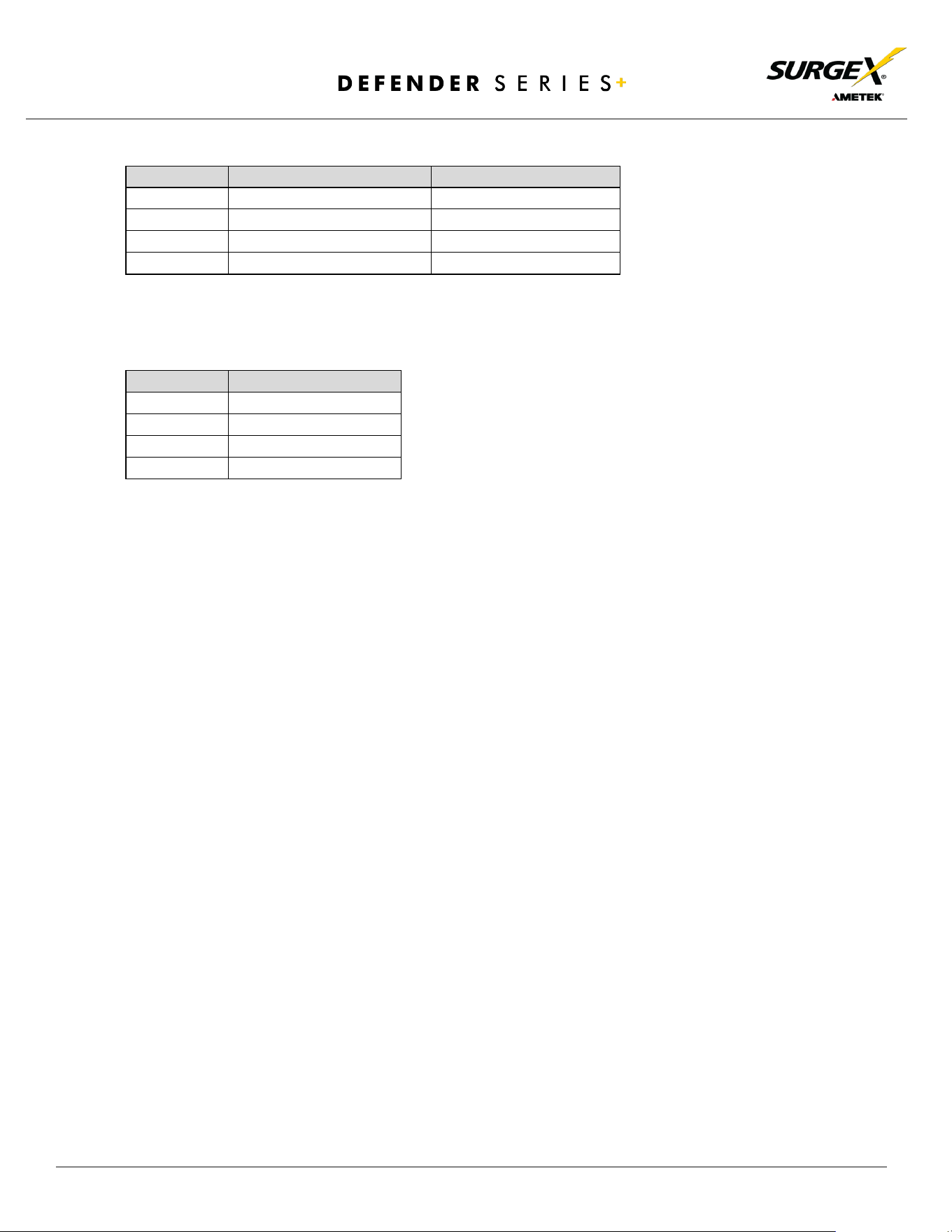
1.3 Rated & Maximum Current
Model
Rated Full Load Current
Maximum Current
SX-DSP-129
12A
15A
SX-DSP-169
16A
20A
SX-DSP-109i
10A
15A
SX-DSP-169i
16A
20A
1.4 Voltage Requirements
Model
Input Voltage
SX-DSP-129
120V AC
SX-DSP-169
120V AC
SX-DSP-109i
240V AC
SX-DSP-169i
240V AC
© 2024 AMETEK SurgeX | Technical Support: 800-645-9721 | surgex.com | B01-00010
7
User Manual
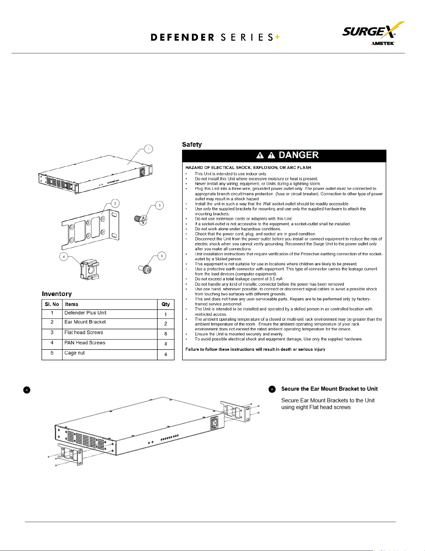
2. Installation and Components
Defender Series+ is designed to be installed horizontally on the equipment rack. The supplied nuts, bolts, and
washers must be used to mount the Defender Series+ to the rack through the mounting holes (A) following the
appropriate local regulations and requirements.
2.1 AC Power: Output
Plug the equipment cord (B) into the suitable receptacles as needed. Please review Introduction, Physical
Interfaces, and Column Outputs for the suitable plugs for each model’s receptacles.
2.2 AC Power: Input
Connect power to the Defender Series+ using an appropriately rated 3 wire grounding type power cord
provided with the equipment in inlet (V). Do not plug the unit into a relocatable power tap. Check the outlet for
correct polarity and presence of a ground conductor before plugging the unit in.
2.3 Ethernet and Account Admin Password
The RJ45 connector for Ethernet (D) is situated on the front panel. The default IP Address is DHCP assigned.
To find IP address of the device, please use the discovery tool at ametekesp.com
. The mDNS protocol is supported
for dynamic device discovery.
The d
efault username is admin, and the default password is Adm1nXXXXXX where XXXXXX are the last six
characters of the MAC address.
2.4 USB-Micro AB
The USB-Micro AB connector (E) is for diagnostics and troubleshooting IP connectivity issues and is only to
be used for setup and debugging. To use, please use the discovery tool at ametekesp.com
or manually enter the static
IP address https://169.254.10.100 into a supported browser. The web server will always be accessible at
https://169.254.10.100 through this USB port. The web server on this interface cannot be changed and will always
be unsecured HTTP at port 80.
2.5 LED
Indicators:
The receptacles have individual power indicator LEDs (F). These are paralleled in the control interface. In
addition, the unit has an LED indicating power (G). Self -Test is indicated by (C).
SX-DSP-129
SX-DSP-169
SX-DSP-109i
SX-DSP-169i

© 2024 AMETEK SurgeX | Technical Support: 800-645-9721 | surgex.com | B01-00010
8
User Manual
2.6 Buttons
2.6.1 Resettable fuse
The resettable fuse (H) is used to reset the Defender Series+ in case the fuse is tripped. This is a single push
button to the bottom left of the Ethernet RJ45 jack. Also, there is a reset switch for hardware and another
for software.
2.6.2 Hardware Reset
Hardware Reset (I): The Hardware Reset button performs a hard reboot of the processor. This hard
reboot will immediately switch controlled outlets off, removing power to connected equipment on
all outputs.
2.6.3 Software Reset
Software Reset (J): The Software Reset button is a multi-functional control depending on length of
press. If the button is held for longer than 10 seconds, the unit resets itself to factory defaults, and
all custom configurations are erased. If the button is held for less than 10 seconds, the unit will
perform a software reset that will not reset any data or power cycle the connected equipment.
© 2024 AMETEK SurgeX | Technical Support: 800-645-9721 | surgex.com | B01-00010
9
User Manual
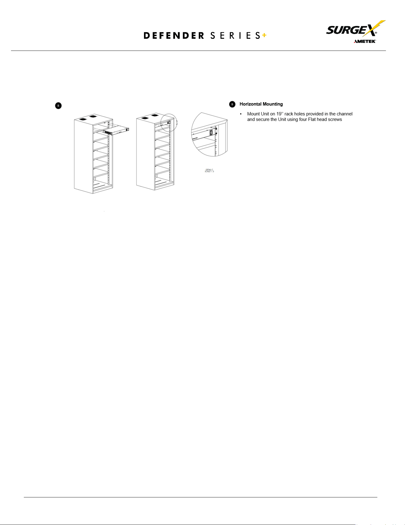
3. Rack Installation
Defender Series+ is designed to be installed horizontally in the equipment rack. The supplied nuts, bolts,
and washers must be used to mount the Defender Series+ to the rack through the mounting holes (A)
following the appropriate local regulations and requirements.
© 2024 AMETEK SurgeX | Technical Support: 800-645-9721 | surgex.com | B01-00010
10
User Manual
© 2024 AMETEK SurgeX | Technical Support: 800-645-9721 | surgex.com | B01-00010
11
User Manual
4. Web Server
Defender Series+’s internal web server provides a comprehensive portal for configuration,
monitoring, and control.
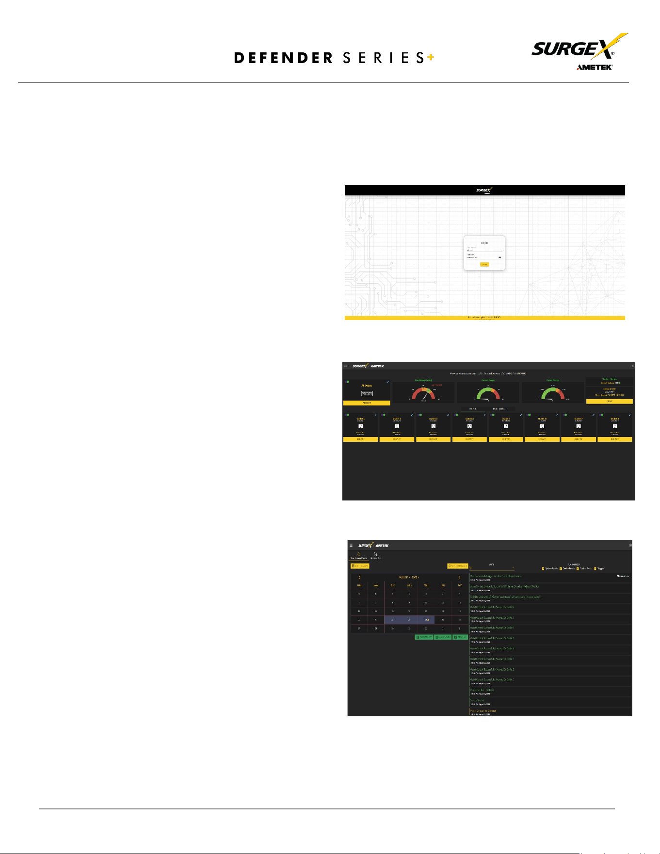
4.1 Login
The Login page is the first page displayed
when a web browser makes a connection to
the Defender Series+. Enter a valid username
and password in the “User Name” and
“Password” fields, and press “Login” to log in.
4.2 Power Management
The Power Management page provides
information and status for the PDU and
individual outlets, as well as basic control of
each outlet. The top right section of the page
provides system status.
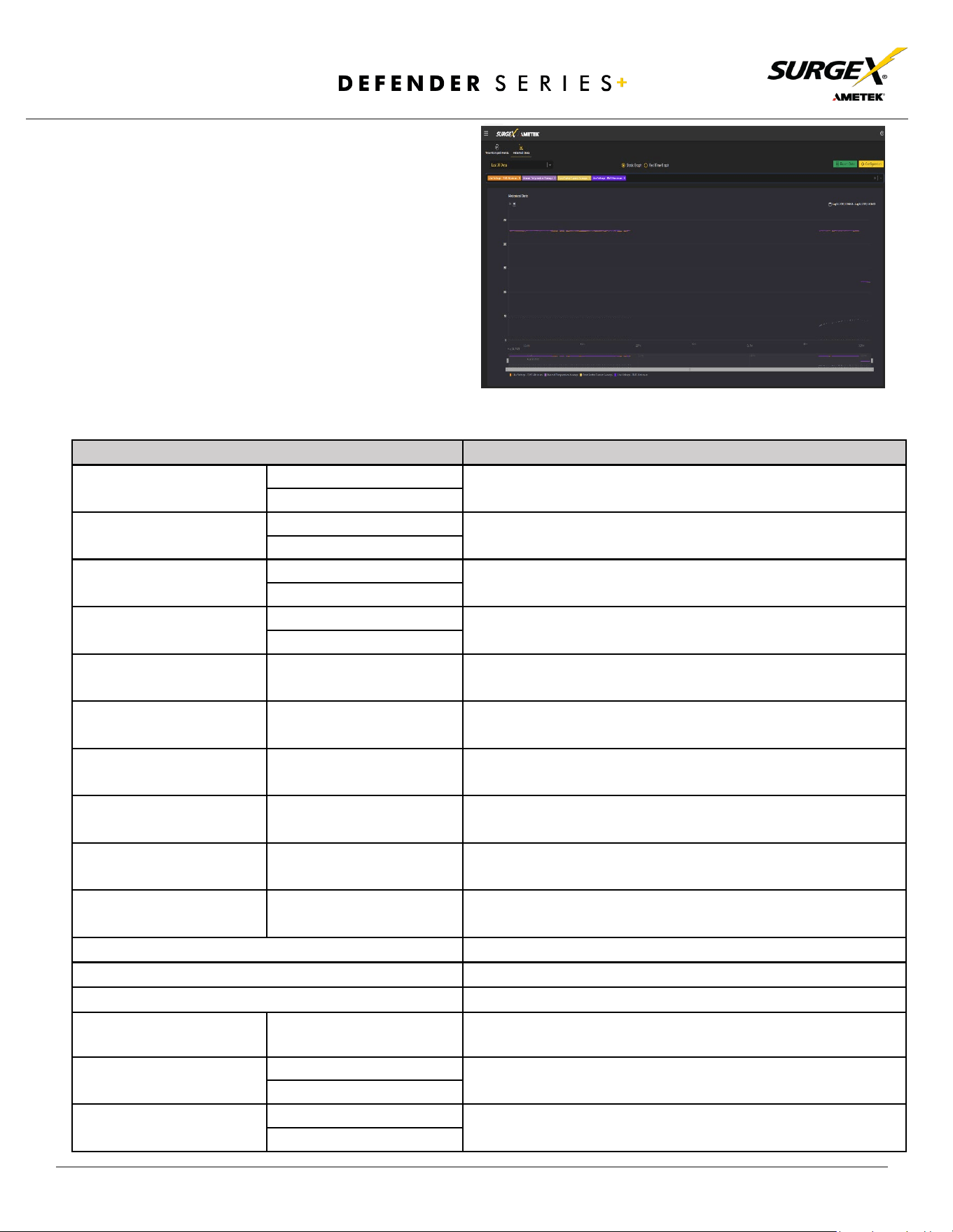
4.3 Reports
The Reports page displays data collected by
the Defender Series+ and stored to its
internal memory. The data is presented in
two groups: Time Stamped Events and
Historical Data. Time Stamped Events are
recorded, with a date and time of occurrence
when a condition meets established criteria.
Defender Series+ uses a Real Time Clock
(RTC) synced to an Internet time server and
backed up by an internal battery. For the
most accurate time stamps and to eliminate
clock drift, we suggest verifying the
NTP connection.
© 2024 AMETEK SurgeX | Technical Support: 800-645-9721 | surgex.com | B01-00010
12
User Manual
The types of events which may be recorded are:
• Triggers
• Power Outage
• Network Events
• Outlet Changes
• Shutdown Events
• Firmware Upgrades
Historical Data is a record of measured electrical
parameters and may be adjusted to sample certain
items at specific intervals. The available
parameters are:
Historical Parameters
Description
Voltage Max
Line - Neutral
The maximum measured RMS voltage between the conductors
during the measurement period.
Neutral - Ground
Voltage Min
Line - Neutral
The minimum measured RMS voltage between the conductors
during the measurement period.
Neutral - Ground
Voltage Average
Line - Neutral
The average measured RMS voltage between the conductors
during the measurement period.
Neutral - Ground
Voltage Peak Max
Line - Neutral
The maximum measured peak voltage between the conductors
during the measurement period.
Neutral - Ground
Current Max
Total Device
The maximum measured RMS current during the measurement
period.
Current Average
Total Device
The average measured RMS current during the
measurement period.
Current Peak Max
Total Device
The maximum measured peak current during the
measurement period.
Power Max
Total Device
The maximum measured average power during the
measurement period.
Power Average
Total Device
The average measured average power during the
measurement period.
Power Peak Max
Total Device
The maximum measured peak power during the
measurement period.
Frequency Max
The maximum measured AC line frequency.
Frequency Min
The minimum measured AC line frequency.
Frequency Average
The average measured AC line frequency.
Power Factor Mode
Total Device
The most recorded power factor during the measurement
period.
Crest Factor Max
Line Voltage
The maximum crest factor calculated during the
measurement period.
Neutral - Ground Voltage
Crest Factor Min
Line Voltage
The maximum crest factor calculated during the
measurement period.
Neutral - Ground Voltage
© 2024 AMETEK SurgeX | Technical Support: 800-645-9721 | surgex.com | B01-00010
13
User Manual
Energy Usage
Total Device
The accumulated energy consumed by connected equipment
during the measurement period.
4.4 Setup
Complete setup and configuration of Defender Series+ is provided via 6 Setup web pages. Each setup
page is described in the following sections. Each setup page has a save button at the bottom of the page
which must be pressed to keep the configuration changes. A green success message will temporarily
appear in the top right of the page when the settings are saved properly.
Setup
Setup Page
Description
Device
Configure basic device parameters
Device Configuration
Configure settings for visual feedback and power up procedure
Outlet Configuration
Configure controllable outlet settings
Outlet Group Configuration
Create, Edit, or Delete outlet groups
Date/ Time Settings
Configure NTP server or set manual time
Network
Configure network settings, including the network adapter and time
keeping
Network Advanced
Configure advanced monitoring and security settings
SNMP
Configure SNMP connection and communication settings
802.IX Settings
Configure authentication settings and/or view connection logs
LDAP Client Settings
Configure LDAP authenticator, options, and test connection
Users
Configure and modify user accounts
Triggers
Create and modify triggers
Threshold with Samples
Configure triggers based on measurements
AutoPing
Configure triggers based on pinging IP addresses
Schedule
Configure triggers based on time
Sequences
Create and modify custom sequences
© 2024 AMETEK SurgeX | Technical Support: 800-645-9721 | surgex.com | B01-00010
14
User Manual
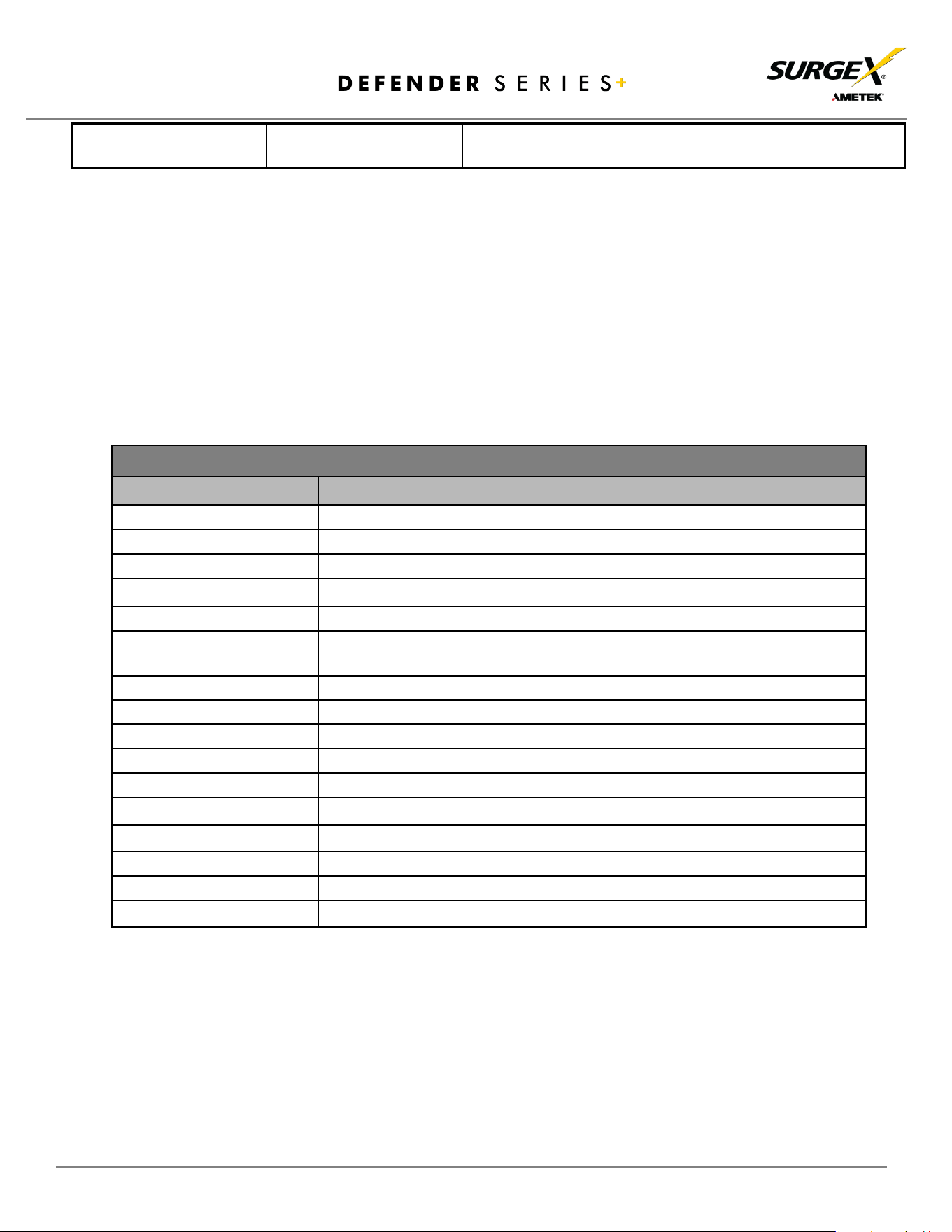
4.4.1 Device Setup
The Device Setup page allows for the specification of basic device parameters.
4.4.1.1 Device Configuration
The Device Configuration tab allows for the specification of visual feedback and device
initialization.
Device Configuration
Item
Description
Device Name
Specifies the name label to be associated with this Defender Series+ device.
Nominal Voltage
Specifies the expected voltage on the input receptacle. This selection does NOT change
any settings for over/under voltage shutoff. This is only for visual coloring on gauges.
Nominal Frequency
Specifies the expected frequency on the input receptacle. This selection does NOT
change any settings for triggers. This is only for visual coloring on gauges.
Power Up Delay Time
Specifies the amount of time in seconds by which to stagger the manual turning on of
multiple outlets when applying the initial state.
On Power Up
Specifies whether to set outlets to initial states run a predefined sequence when
Defender Series+
device powers up or the hard reset button is pushed.
On Shutdown Clear
Specifies whether to set outlets to initial states run a predefined sequence when
Shutdown state clear.
Temperature Display
Specifies whether to display temperature in degree Fahrenheit or Celsius.
Auto Logout
Specifies the web security timeout in minutes.
AutoPing Frequency
Specifies how frequent the Defender Series+ device will send pings to an IP Address or
Hostname in an AutoPing trigger.
AutoPing Timeout
Specifies the amount of time the Defender Series+ device will wait for a ping response
before calling the attempt a failure.
© 2024 AMETEK SurgeX | Technical Support: 800-645-9721 | surgex.com | B01-00010
15
User Manual
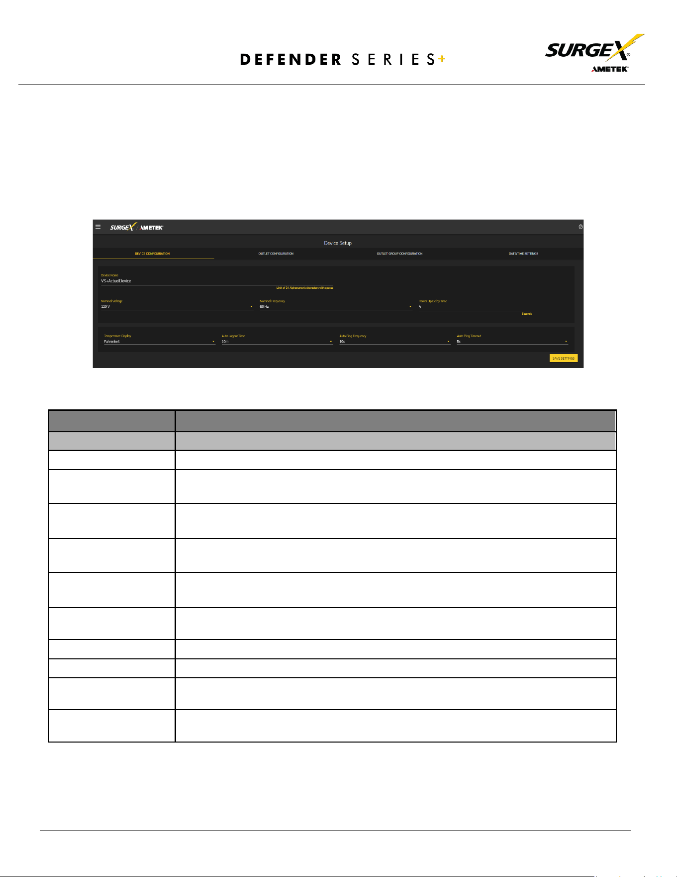
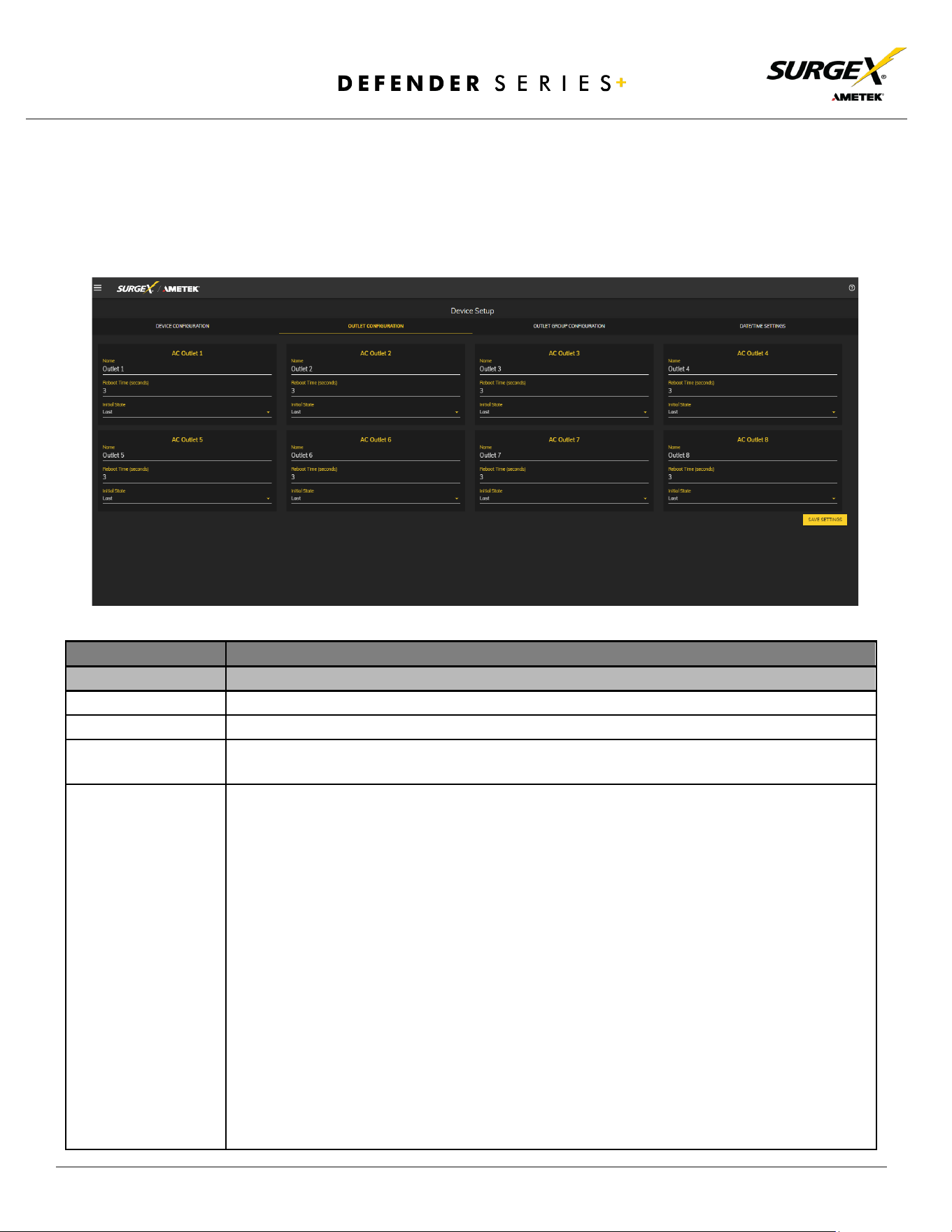
4.4.1.2 Outlet Configuration
The Outlet Configuration tab allows for the specification of unique names and reboot
times per outlet. The configuration for initial state per outlet is also here, if this option is
selected in the Device Configuration tab for either On Power Up or On Shutdown Clear.
Outlet Configuration
Item
Description
Outlet Description
A fixed short phrase that references a physical feature.
Outlet Name
Specifies the name label to be associated with this Outlet.
Reboot Time
Number of seconds that the device will wait in between turning an outlet off and turning
the outlet back on during a reboot command.
Initial State
The state that an outlet will assume during start up or after a shutdown clears, if the initial
state setting is selected in the Device Configuration tab. Options are as follows:
Always On
Regardless of other settings, this outlet will always be on. Ignores Shutdown
state and deselecting Initial State in the Device Configuration tab. Outlet
ignores user commands to reboot or power off. The
only thing that will kill
power with this selected is a hard reboot or an power outage.
Always Off
The opposite of Always On, this setting will never allow an outlet to pass
powe r.
On
The outlet will start in an On state.
Off
The outlet will start in an Off state.
Last
The outlet will assume the last state it was in. (Factory Default)
Reboot Only
The outlet will act like the On state but will ignore user commands to power
off. This outlet will only respond to reboot commands. Useful for network
appliances that may need to be rebooted, but otherwise want to be on all
the time. Using this setting, the outlet will still turn off during Shutdown
state.
© 2024 AMETEK SurgeX | Technical Support: 800-645-9721 | surgex.com | B01-00010
16
User Manual
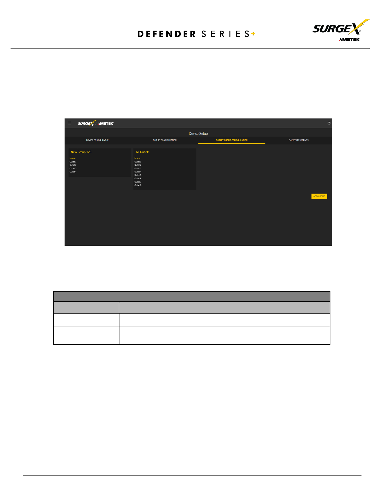
4.4.1.3 Outlet Group Configuration
The Outlet Group Configuration tab allows for the specification of visual feedback and
device initialization.
Outlet Group Configuration
Item
Description
Group Name
Specifies the name label to be associated with the outlet group.
Member Name
Specifies the outlet members of this outlet group.
© 2024 AMETEK SurgeX | Technical Support: 800-645-9721 | surgex.com | B01-00010
17
User Manual
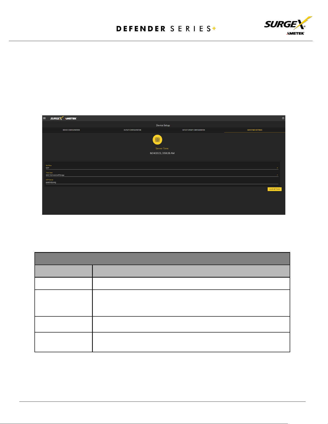
4.4.1.4 Date/Time Settings
The Date/Time Settings tab allows for the specification of visual feedback and device
initialization.
Date/Time Configuration
Item
Description
Server Time
Returns the device's internal time based on the local time zone.
Set Time
Specifies the method for setting the time in the Defender Series+ device.
Options for this setting are NTP or manual. NTP will use the NTP Server option
to automatically sync the device time every day.
Time Zone
Specifies the desired time zone adjustment for the Defender Series+ device.
NTP Server
Specifies the hostname or IP address of the NTP server to use for time
synchronization.
© 2024 AMETEK SurgeX | Technical Support: 800-645-9721 | surgex.com | B01-00010
18
User Manual
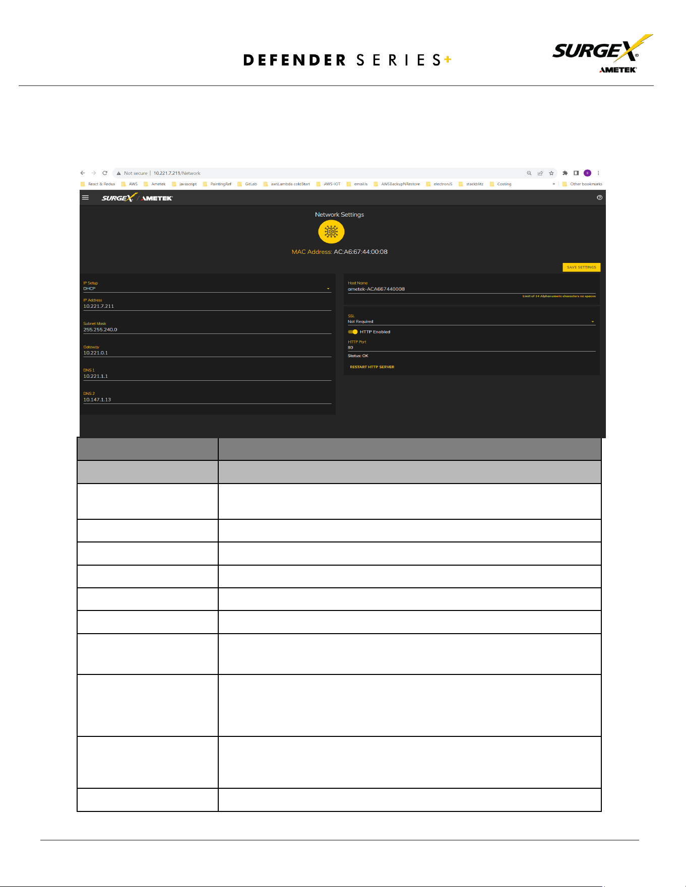
4.4.2 Network Setup
The Network Setup page allows for the specification of network settings, including the
network interface and NTP time server.
Network Configuration
Item
Description
Setup
Specifies if the device will have a static IP Address or will dynamically be
assigned network settings through DHCP.
Address
Current IP Address of the network interface on the RJ45 Ethernet port
Subnet Mask
Current Subnet Mask of the network interface on the RJ45 Ethernet port.
Gateway
Current Gateway of the network interface on the RJ45 Ethernet port
DNS 1
Current DNS1 of the network interface on the RJ45 Ethernet port.
DNS 2
Current DNS2 of the network interface on the RJ45 Ethernet port.
Hostname
A configurable unique name to be used to access the device instead of an
IP Address.
SSL
Specifies whether the web server will be SSL encrypted (HTTPS) or not
(HTTP). The default certificate is self-signed and will require the user to
continue through a safety notification if a custom signed certificate is not
uploaded to the device.
HTTP Enabled
Specifies if the web server is enabled or disabled. NOTE: If disabling the
web server, the web interface end REST API will be disabled, only limited
functionality over SNMP will remain enabled.
HTTP Port
Port number to use for the web server.
© 2024 AMETEK SurgeX | Technical Support: 800-645-9721 | surgex.com | B01-00010
19
User Manual
4.4.3 Network Advanced Setup
The Network Advanced Setup page allows for the specification of more advanced network
security and monitoring options.
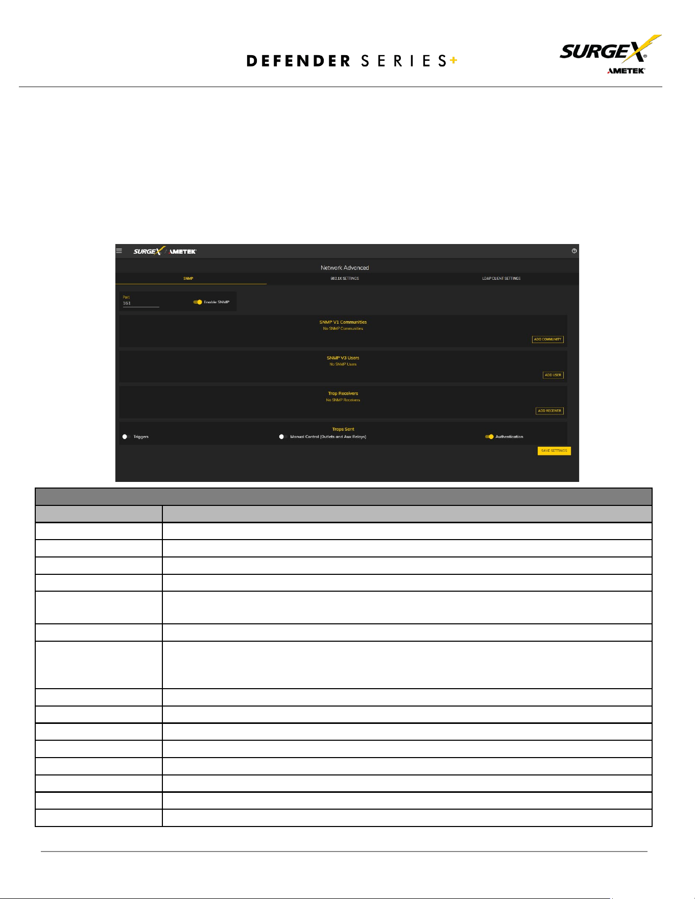
4.4.3.1 SNMP
The SNMP tab allows for the specification of parameters for the SNMP agent,
supporting V1 through V3.
SNMP Setup
Item
Description
Enable SNMP
Specifies whether to enable the SNMP agent.
Port
Specifies the port number for the SNMP agent. 161 is the standard SNMP port.
SNMP V1 Communities
Is a table of all SNMP communities, supporting SNMP V1 at a minimum.
Name
Specifies the Community name for read and/or write access.
Source
Specifies an unrequired whitelist. If requests are not to be filtered by hostname or IP Address,
this field can be left blank.
Access
Specifies the type of access allowed by the community.
SNMP V3 users
Is a table of Users specifically for SNMP V3 authorization. Users here will not apply to the REST
API, and REST API users will not be able to authenticate via SNMP V3 without redefining their
credentials here. SNMP credentials cannot be authenticated using the LDAP Client.
Name
The name or username for authorization.
Authorization
Type of encryption used per user. Options are DES or MD5.
Access
Type of access per user. Options are Read Only or Read/Write.
Passphrase
Passphrase or password for the user.
Trap Receivers
Is a table of all the destinations for SNMP traps.
Name
The name of the community for traps.
Host Name
The hostname or IP address of the SNMP Manager that is going to receive traps.
Port
The port number that the SNMP Manager is listening for traps on.
© 2024 AMETEK SurgeX | Technical Support: 800-645-9721 | surgex.com | B01-00010
20
User Manual
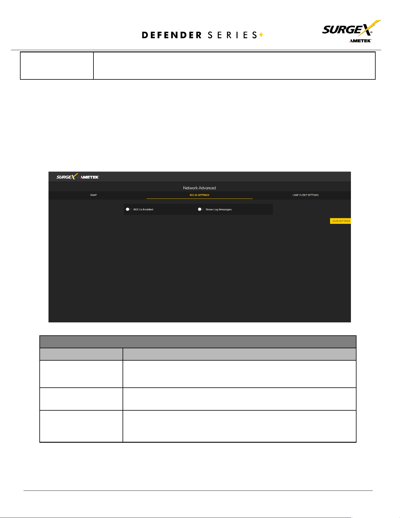
4.4.3.2 802.1X Settings
The 802.1X Settings tab allows for the specification of 802.1X authentication and
debugging of errors as they may arise.
Traps Sent
Specifies which specific traps are to be sent. Triggers send traps for Triggering and Clearing.
Manual Control sends traps for outlet state changes, and Authentication sends traps for failed
authentication attempts.
802.1X Settings Setup
Item
Description
802.1x Enabled
Enables the 802.1x authentication client. This does not require the user to have
a unique password
for Defender Series+ device. Network login credentials can
be used.
Show Log Messages
Opens and hides a table with date/time coded 802.1x related messages for
debugging an authentication failure.
Authentication Type
Specify the authentication method used during the 802.1x negotiation.
Different authentication options and settings will be displayed based on the
selected Authentication Type.
© 2024 AMETEK SurgeX | Technical Support: 800-645-9721 | surgex.com | B01-00010
21
User Manual
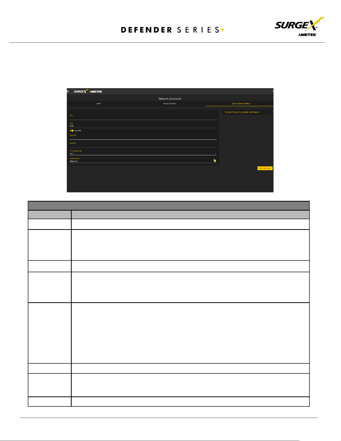
4.4.3.3 LDAP Client Settings
The LDAP Client Settings tab allows for the specification of the LDAP Authentication
server and authentication method and a test interface to test the server setup.
LDAP Client Settings Setup
Item
Description
Host
The hostname or IP address of the LDAP server.
Use SSL
A switch that will enable or disable SSL when attempting to connect to the LDAP server. This is
a separate option than the port number, in the case that a site is using a nonstandard port for
authentication but still wants the ability to specify encryption.
We always suggest using
encryption when using LDAP.
Base DN
The base point in the directory tree where the user distinguished name search will begin.
User DN
The distinguished name of a user that will be used to authenticate. Multiple users are
supported by using macros. For example, in the above image, the username test User attempts
to log in, and the User DN pulls the name "Test User" from the user's definition
for use in the
authentication to replace the string %Full Name%.
TLS Require Cert
This specifies how to handle server certificates during TLS negotiations. Never: the client never
asks the server for a certificate. Allow: the client will ask for a certificate
; if none is provided,
the session proceeds normally. If a certificate is provided but the client is unable to verify it, the
certificate is ignored and the session proceeds normally, as if no certificate had been provided.
Try: the certificate is requested, and if none is prov
ided, the session proceeds normally. If a
certificate is
provided and it cannot be verified, the session is immediately terminated.
Demand: the certificate is requested, and a valid certificate must be provided, otherwise the
session is immediately terminated.
Certificate File
This is the certificate that will be sent to the LDAP Server when/if requested.
User Name
The information for a user that is defined in the Users page. The first part (name), is accessible
by the %Full Name% macro, and the second part (username) is accessible with the %User
Name% macro.
Password
The password for the given user to test the LDAP server configuration.
© 2024 AMETEK SurgeX | Technical Support: 800-645-9721 | surgex.com | B01-00010
22
User Manual
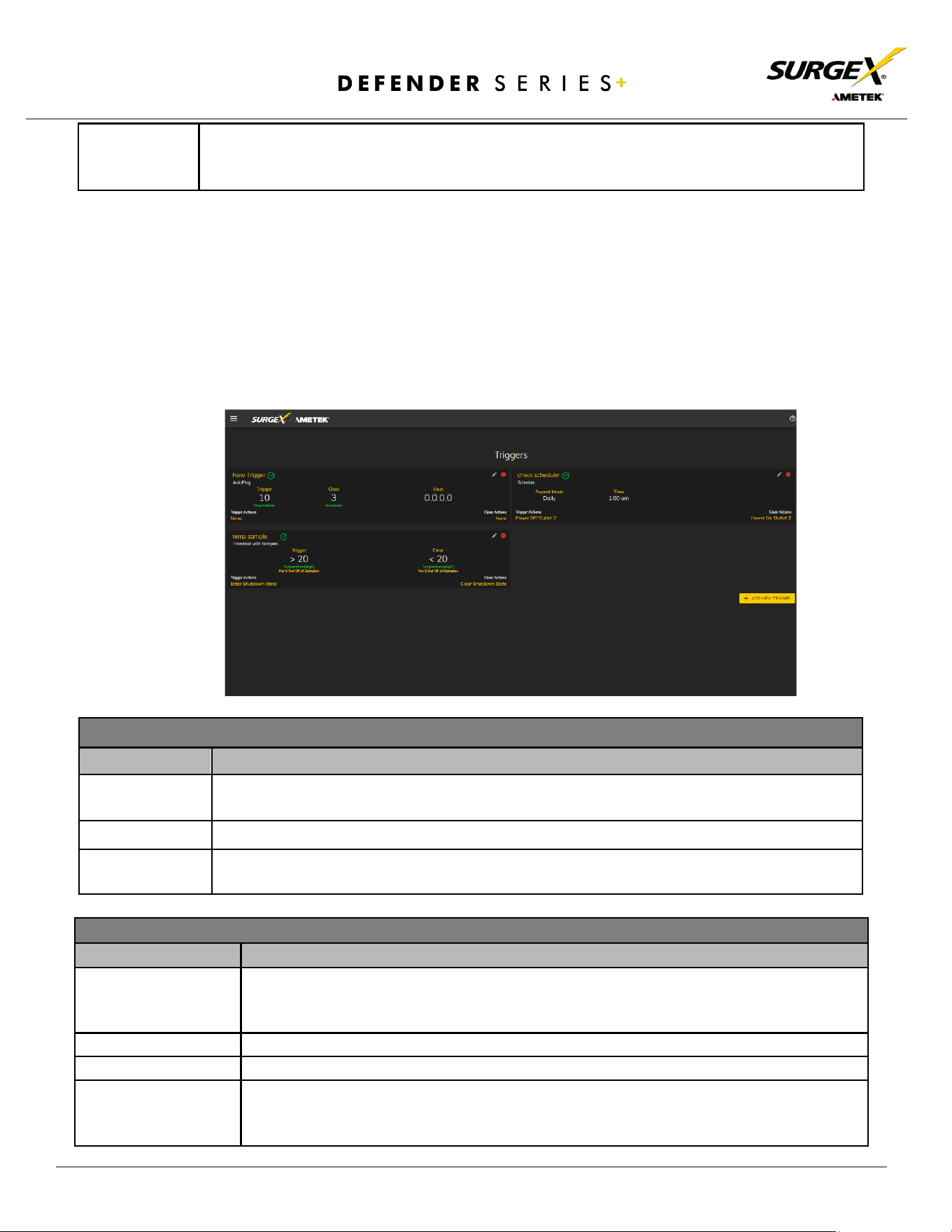
4.4.4 Triggers Setup
The Triggers Setup page allows for the modification of triggers. Triggers define event logging
parameters and allow configuration to automatically control and protect connected
equipment. Triggers are categorized into three types: AutoPing, Threshold with Samples, and
Schedule, but all have the same possible actions. Actions can either be on the onset
(Trigger/Alarm Actions) or offset (Clear Actions) of a trigger. All Triggers are logged along with
the associated actions.
Action Types
Item
Description
None
Do not take any action; only log the event. This is useful as a Clear Action when an
action should persist, or for both Alarm and Clear actions when just logging the event is
desired.
Power On
Power on a specific outlet if the outlet configuration allows it.
Power Off
Power off a specific outlet if the outlet configuration allows it.
Reboot
Reboot a specific outlet if the outlet configuration allows it. If an outlet is already off
when this command is issued, the outlet will simply turn on after the outlet specific
reboot delay time.
Test User
A button to send an authentication request using the given settings for the user and password
above. NOTE: Settings should be saved using the "Save Settings" button at the bottom of the
page before testing a configuration change.
Trigger Types
Item
Description
Threshold with
Samples
Uses measurements over an allotted time to take an action. This trigger type is
configurable to act very quickly or very slowly depending on environmental/system needs.
AutoPing
Issues a ping function on a periodic basis to determine if an IP asset is accessible.
Schedule
Uses the device time to issue a one time or periodic command. We suggest ensuring the
NTP server is updating correctly to use the schedule trigger.

© 2024 AMETEK SurgeX | Technical Support: 800-645-9721 | surgex.com | B01-00010
23
User Manual
Run Sequence
Run a specific sequence.
Enter Shutdown
State
Put the device into a shutdown state. This state turns off all outlets (unless they are
configured for always on). The only way to clear a shutdown state, is another trigger, a
button on the web interface, or a REST API command.
Clear Shutdown State
Clear the device's shutdown state. Clearing the device's shutdown state will cause the
outlets to follow the logic defined by the On Shutdown Clear setting.
© 2024 AMETEK SurgeX | Technical Support: 800-645-9721 | surgex.com | B01-00010
24
User Manual
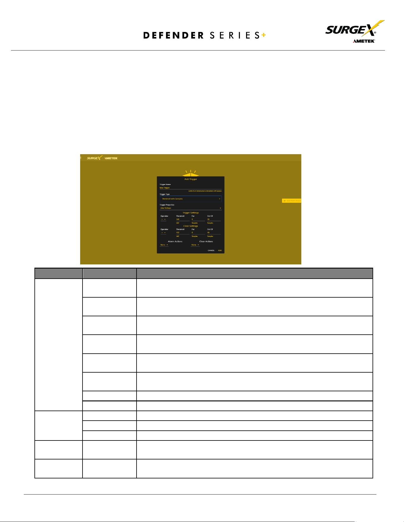
4.4.4.1 Threshold with Samples
The Threshold with Samples trigger uses several measurements to decide when to act. The
trigger can be configured to act quickly or slowly, depending on the number of
measurement samples used. A new sample is available every 50ms, with the minimum
samples being used for a trigger being 1 sample and the maximum being 20 samples.
Threshold with Samples triggers are evaluated every time a new sample is available. Based
on the below “New Trigger” example below, the trigger will alarm or turn on after 5 of any
consecutive 10 samples are above 140V.
Item
Options
Description
Trigger
Properties
Line Voltage
Uses the Line to Neutral voltage measurement. Measurement accuracy is
between 90 VAC and 300 VAC.
N-G Voltage
Uses the Neutral to Ground voltage measurement. Measurement accuracy is
between 0.6 VAC to 300 VAC.
Current
Uses the current measurement, which includes total product current.
Measurement accuracy is between 0.1 A and 20 A.
Temperature
Uses the internal temperature measurement. This should not be treated as an
ambient temperature and will vary drastically based on loading.
Frequency
Uses the frequency measurement. Measurement accuracy is between 45 Hz
and 65 Hz.
Average Power
Uses the average power measurement. Measurement accuracy is between 12W
and 6000W.
Crest Factor
Uses the Line to Neutral Voltage Crest Factor.
Power Factor
Uses the Power Factor.
Operator
>
Requires "For" number of measurements to be greater than the threshold.
<
Requires "For" number of measurements to be less than the threshold.
=
Requires "For" number of measurements to be exactly equal to the threshold.
Threshold
Numerical Range
Is the number to be evaluated against all measurements to either trigger or
clear the trigger.
For
1-20
The number of measurements out of the given number of samples being
evaluated that must meet the criteria to trigger or clear the trigger.
© 2024 AMETEK SurgeX | Technical Support: 800-645-9721 | surgex.com | B01-00010
25
User Manual
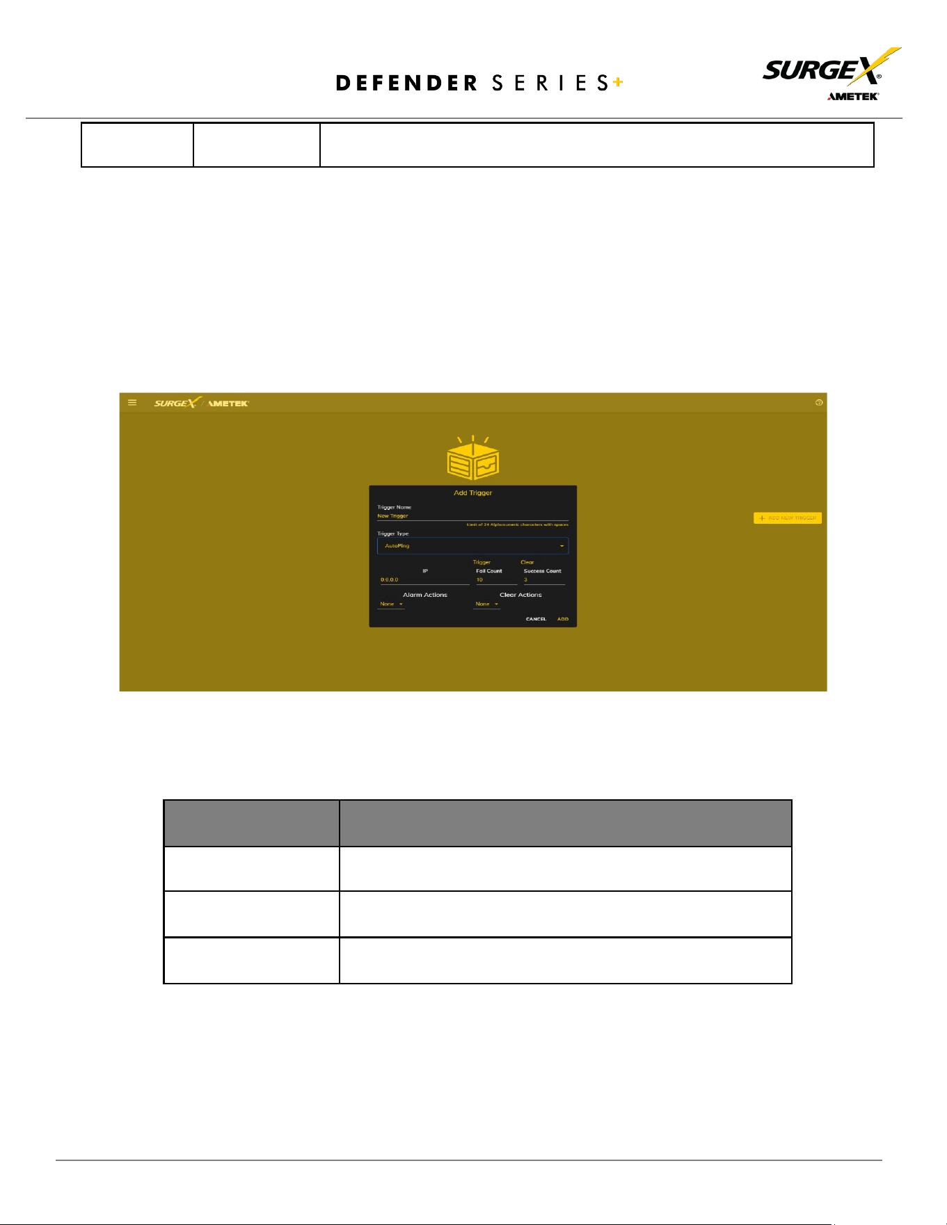
4.4.4.2 AutoPing
The AutoPing trigger uses a ping command on a periodic basis defined in the device settings
to test if a specific IP address will respond. This trigger type is useful if there is a problematic
piece of equipment that becomes unresponsive or if internet connectivity is inconsistent.
Out Of
1-20
The number of consecutive measurements to be evaluated to trigger or clear
the trigger.
Item
Description
IP
IP address to be pinged at the period set on the device
configuration page.
Fail Count
Number of consecutive failed ping responses needed to trigger
the AutoPing trigger.
Success Count
Number of consecutive successful ping responses needed to
clear the AutoPing trigger.
© 2024 AMETEK SurgeX | Technical Support: 800-645-9721 | surgex.com | B01-00010
26
User Manual
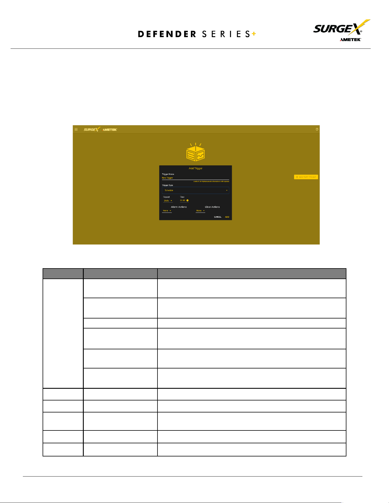
5.4.4.3 Schedule
The Schedule trigger uses the internal time of the SQUID to easily configure single and
recurring events based on time. Only Alarm Actions are used for this trigger.
Item
Options
Description
Repeat
Never
The trigger will only fire when the time reaches the time shown
in the configuration the next time.
One Time
The trigger will only fire once on the specific date and time
shown in the configuration.
Daily
The trigger will fire every day at the given time.
Weekly
The trigger will fire every week on the selected day(s) at the
given time.
Monthly
The trigger will fire every month on the given day of the month
at the given time.
Annually
The trigger will fire every year on the given day of the given
month at the given time.
Date
Date Picker
A specific date to be used in the One-Time trigger.
Days
Sunday - Saturday
A set of day(s) that can be selected for use in the Weekly trigger.
Day
1-31
A day of the month to be used in the Monthly or Annually
trigger.
Month
January - December
A month of the year to be used in the Annually trigger.
Time
12:00 AM - 11:59 PM
A given time to be used in all scheduling triggers.
© 2024 AMETEK SurgeX | Technical Support: 800-645-9721 | surgex.com | B01-00010
27
User Manual
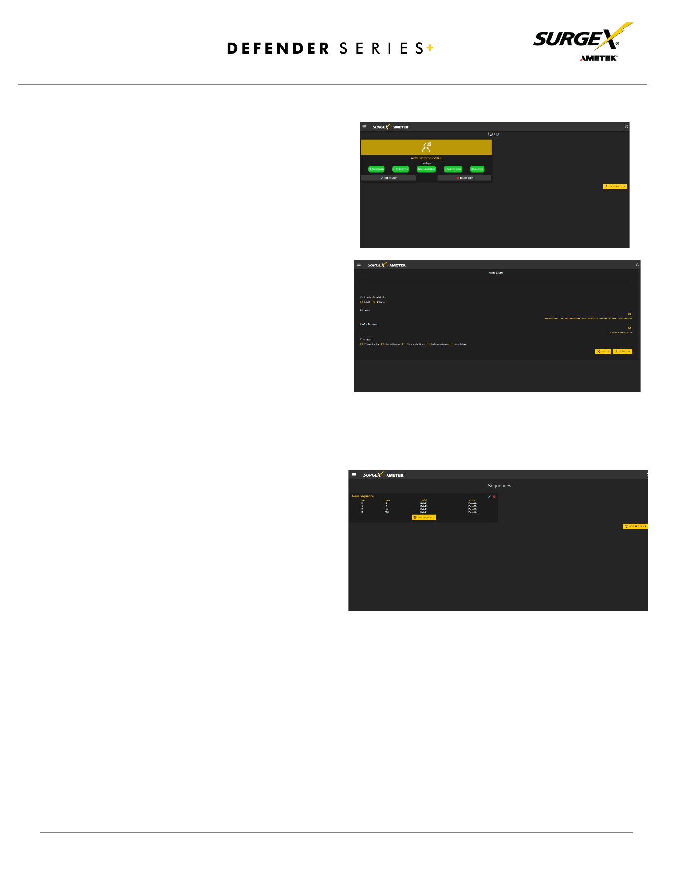
4.4.5 Users Setup
The Users Setup page allows for the
creation, deletion, and editing of user
accounts. Each user will have a unique
name, username, authentication mode, and
may be assigned access to specific features.
LDAP and Internal authentication modes are
supported.
The following privileges may be assigned or
revoked as necessary:
• Trigger Config
• Device Control
• Network Settings
• Software Update
• User Administration
4.4.6 Sequences Setup
The Sequences Setup page allows for the
creation and modification of sequences. A
sequence is a set of actions to be
taken in a specific order and with a
specified delay time between each
step. Using sequences avoids manually
performing each action or turning
each outlet on or off individually.
A sequence, as defined for this product, is purely a one-way sequence. That is, you do not use the
same sequence to turn outlets on as you use to turn the same outlets off in reverse order. One
sequence must be created for the turn-on function and then a second sequence must be created for
the turn-off function.
To create a new sequence, press the “Add Sequence” button. The new sequence must be given
a unique name. This name should clearly indicate what the sequence will do, such as “All On”, “All
Off”, or “Stage Equipment On”.
To run a sequence to test it, press “Run Sequence”. To edit an existing sequence, press the pencil icon.
To delete a sequence, press the minus “-“ icon.
© 2024 AMETEK SurgeX | Technical Support: 800-645-9721 | surgex.com | B01-00010
28
User Manual
After a sequence has been saved, it will be available at the Sequences page and when creating or
editing a trigger when run sequence is selected as an action.
*Time delay is specified from the previous sequence item, not from the initial starting point. For
example, creating a sequence with “Step 1, 1 second, Outlet 1, On” and “Step 2, 1 second, Outlet
2, On” will turn on Outlet 1 after 1 second, and Outlet 2 on 1 second after Outlet 1 has turned on.
This sequence will not turn on both Outlets 1 and 2 at the same time.
Sequence Actions:
• None (useful for additional time delays)
• State Change
o On, Off, or Reboot
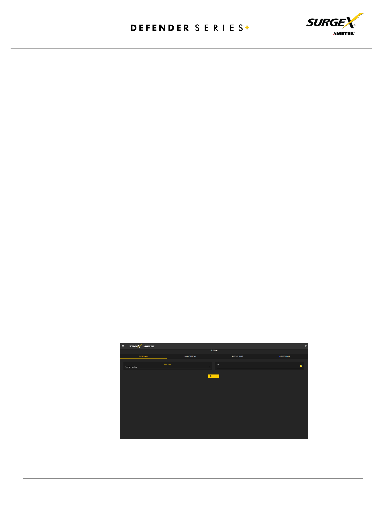
4.5 Utilities
Defender Series+ contains several utilities to ease the configuration and deployment that may be
performed on a per unit basis through several web pages.
4.5.1 File Upload
Defender Series+ allows for a variety of files to be uploaded. This is also the method for
upgrading the firmware. Current firmware versions can be obtained from the SurgeX website.
Defender Series+ will not automatically contact SurgeX servers for new firmware. Other files that
can be uploaded include a variety of certificates and configurations. By default, Defender Series+
ships with a self-signed HTTPS certificate if HTTPS is enabled. A different certificate can be
uploaded for use by the HTTPS server by selecting “HTTPS SSL Certificate” under the File type
drop down.
© 2024 AMETEK SurgeX | Technical Support: 800-645-9721 | surgex.com | B01-00010
29
User Manual
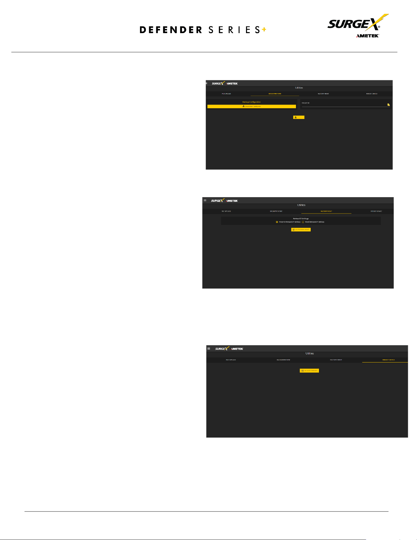
4.5.2 Backup/Restore
The current configuration may be
saved to a file and downloaded for
archival. Previously stored
configurations may be applied to other
units to easily mass configure a larger
deployment. IP Settings will not be
saved in the Backup Configuration.
4.5.3 Factory Reset
Factory default settings may be
applied through the web interface.
• Option to keep or reset network IP
settings. - Web Server settings will be
reset. A custom port number will be
reset to 80 and SSL will be disabled
by default.
4.5.4 Soft Reboot
Adds the ability to reboot the Defender
Series+ processor. A soft reboot will not
change the outlet state or disconnect
power from connected equipment. This
request will add a message in the event
log “Rebooting Adapter Due to User
Request”.

© 2024 AMETEK SurgeX | Technical Support: 800-645-9721 | surgex.com | B01-00010
30
User Manual
5. Security
Defender Series+ has been designed with security as a priority. All ports and features may be changed or disabled.
5.1 Authentication
Defender Series+ supports basic and secure authentication for users and network connections.
5.1.1 802.1X
802.1X network authentication may be enabled for networks requiring supplicant authentication.
5.1.2 SSO (Single Sign-On)
Defender Series+ users may be configured to use either Internal or SSO (Single Sign-On) authentication.
Internal authentication uses basic usernames and passwords assigned by the administrator on a per-unit
basis. SSO authentication uses LDAP (Lightweight Directory Access Protocol) to authorize users and
determine their level of privileges using Microsoft® Active Directory. While it is possible to use LDAP to
authorize users without SSL encryption, we suggest only configuring the connection to the authentication
server using SSL encryption to plain text network traffic.
5.2 Interfaces
5.2.1 Network Interface
• Web Server: It is possible to enable and disable the internal web server, change the security from none
(HTTP) to TLS 1.2 (HTTPS), as well as change its port. These settings also apply to the REST API.
• S
NMP: SQUID supports SNMP V3 for secure communications with the ability to enable and disable.

© 2024 AMETEK SurgeX | Technical Support: 800-645-9721 | surgex.com | B01-00010
31
User Manual
6. Application Programming Interfaces (APIs)
Defender Series+ is designed for flexible communication and integration with diverse control and monitoring
platforms.
6.1 HTTP/HTTPS REST
Defender Series+ includes an extensive HTTP API (HTTPS when security is enabled) in JSON format. Full
protocol details are available at https://www.ametekesp.com
.
6.2 Interfaces
SNMP V3 communications are intended to provide essential items for management. Read, Write, Table, and
Trap objects will be included. Full protocol details, and the SNMP MIB, are available at
https://www.ametekesp.com
.

© 2024 AMETEK SurgeX | Technical Support: 800-645-9721 | surgex.com | B01-00010
32
User Manual
7. Part Numbers
7.1 Part Number Scheme
Product Line
SX-DSP
( Defender Series+ )
Rated Current
10
15A Max
Current
12
15A Max
Current
16
20A Max
Current
Number of Receptacles
9
9 Receptacles
NEMA / IEC Model
i
IEC Model (240V)
blank
NEMA Model
(120V)
SX - DSP - 12 - 9 i

© 2024 AMETEK SurgeX | Technical Support: 800-645-9721 | surgex.com | B01-00010
33
User Manual
8. Troubleshooting
1) Checking for power input issues -
a) Verify if the power source is functioning correctly and ensure that all connections are secure.
b) Verify the circuit breaker.
c) Verify the incoming line cord to the device is accidentally disconnected or if the mains plug is
pulled out from the wall receptacle.
2) Diagnosing overloading issues - Check if the device is being overloaded by too many connected devices or
if there is a problem with the power distribution unit. Please refer to the Overload current specification
table.
3) Inspecting for physical damage - Check for any signs of physical damage such as bent pins, frayed cords,
or broken components.
4) Testing voltage levels - Verify that the voltage levels are within the appropriate range for the specific
device and check for any voltage fluctuations or spikes. Improper mains voltage to the device may result in
fire.
5) Checking for firmware or software issues - Ensure that the firmware or software of the device is up-to-
date and functioning correctly.
6) Investigating environmental factors - Check for any environmental factors that may be affecting the
device such as extreme temperature or humidity.
7) Replacing a component or subsystem in the device without a trained technician may lead to device
malfunctionn.
8) Contacting customer support - If the above troubleshooting methods do not resolve the issue, the user
may be advised to contact customer support for further assistance.
Rated Current
Maximum Current
10A
15A
12A
15A
16A
20A
© 2024 AMETEK SurgeX | Technical Support: 800-645-9721 | surgex.com | B01-00010
34
User Manual
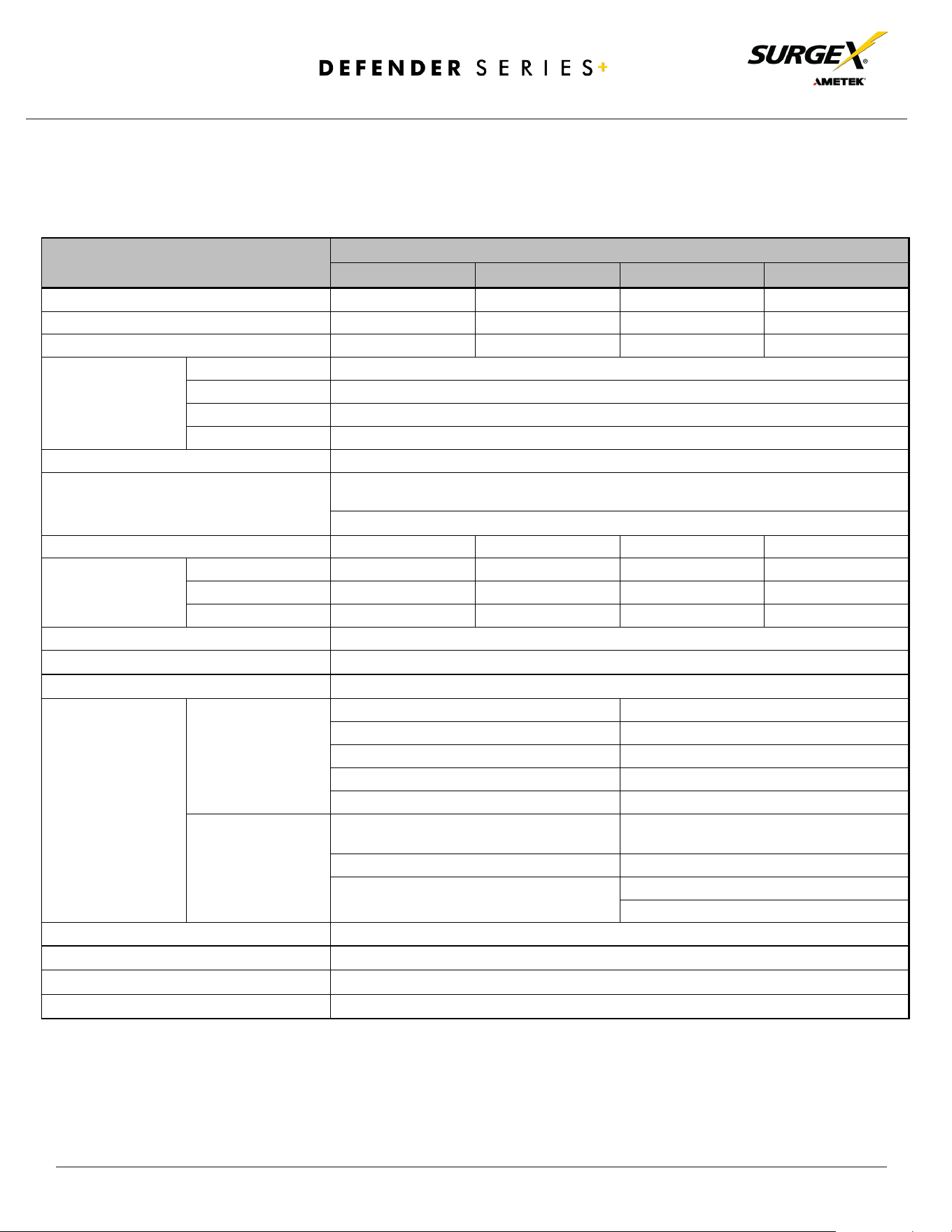
9. Specifications
Parameter
Item Number
SX-DSP-129
SX-DSP-169
SX-DSP-109i
SX-DSP-169i
AC Load Rating
12A @ 120V 16A @ 120V 10A @ 240V 16A @ 240V
No of Outlets - Back
8
8
8
8
No of Outlets - Front
1
1
1
1
Measurement
Accuracy
Voltage
± 2%
Current ± 5%
Power
± 5%
Energy
± 5%
Timestamp Accuracy
± 1%
Network Port
10/100 Ethernet connection on Female RJ45, Auto Negotiating with 10/100 network
connections with Link and Activity LEDs
USB RNDIS Device on micro-AB
Weight
7.5 Lbs/3.4Kg
7.5 Lbs/3.4Kg
7.05 Lbs/3.2Kg
7.05 Lbs/3.2Kg
Dimensions
(Enclosure)
Height
1.73”/44mm
1.73”/44mm
1.73”/44mm
1.73”/44mm
Width
17.4”/442mm
17.4”/442mm
17.4”/442mm
17.4”/442mm
Depth 9.85”/250mm 9.85”/250mm 9.85”/250mm 9.85”/250mm
Temperature Range: 100% Load 0 to 45 °C (32 - 113 °F)
Humidity Range
5% to 95% R.H. Non-condensing
Altitude
0 - 10000ft (0 - 3048meters)
Agency Listings
Safety
Certified to UL 62368-1
Certified to UL 62368-1
Certified to CAN/CSA C22.2 No
CE Mark
RoHS: Compliant
WEEE
Prop 65
RoHS: Compliant
REACH: Compliant
EMC
FCC 47 CFR PART 15 SUBPART B (Using ANSI
C63.4-2014)
EN 55035:2017+A11:2020
ICES-003 ISSUE 7
EN 55032:2015 + A1:2020
EN 61000-3-2:2019 + A1:2021
EN 61000-3-3:2013 + A2:2021
Surge Protection Multi Stage Surge Protection
IP Protection Class
IPX0
AC Power System Type
TN
Pollution Rating
Pollution degree (PD) PD 2
