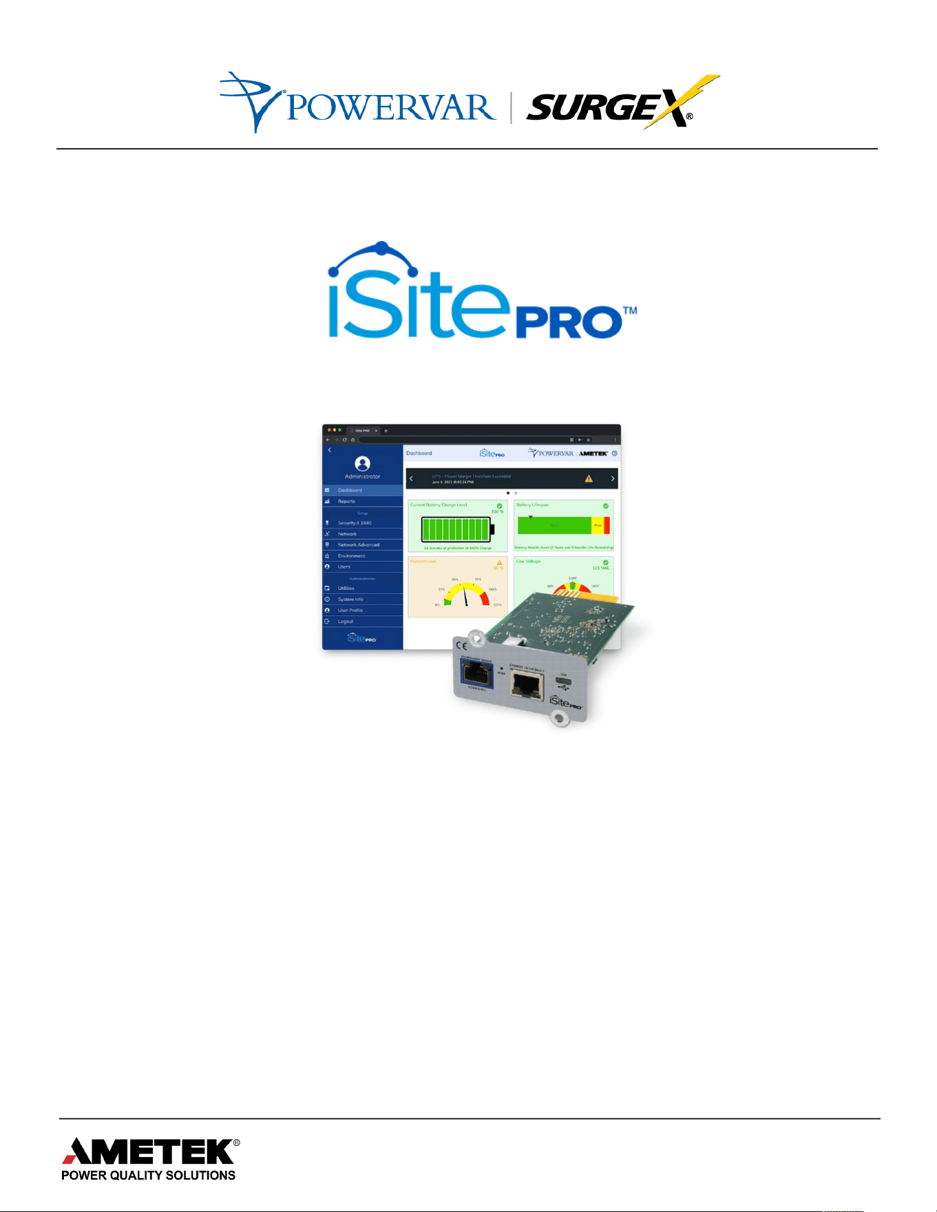
Network Adapter for UPS Management
USER MANUAL
UPS Standalone, UPS Large Format, UPS + Isolation Transformer
© 2021 AMETEK, Inc. | Technical Support 1-800-645-9721 | surgex.com | UM-UPS-SNMP-Rev-B

2
Network Adapter for UPS Management User Manual
© 2021 AMETEK, Inc. / Technical Support: 1-800-645-9721 / surgex.com
TABLE OF CONTENTS
1.0 About This Product .......................................................................................................... 6
1.1 Product Description...................................................................................................... 6
1.2 Simplified Description of Services ................................................................................ 6
1.2.1 Messaging ............................................................................................................ 6
1.2.2 Management......................................................................................................... 6
1.2.3 Shutdown - Future Enhancement.......................................................................... 6
1.3 Security Protocols Supported....................................................................................... 7
2.0 Quick Start ...................................................................................................................... 8
2.1 Physical Installation ..................................................................................................... 8
2.1.1 Hardware Installation ............................................................................................ 8
2.2 Access to the Web Interface ........................................................................................ 8
2.2.1 Connecting to the Web Interface........................................................................... 8
2.2.2 Logging in to the iSite PRO Web Interface ............................................................ 9
2.2.3 Finding MAC Address of iSite PRO....................................................................... 9
3.0 Web Interface Navigation ...............................................................................................10
3.1 Overview.....................................................................................................................10
3.2 Supported Web Browsers ...........................................................................................10
3.3 Logging On .................................................................................................................10
3.4 Dashboard ..................................................................................................................11
3.4.1 UPS Status Window.............................................................................................11
3.4.2 Current Battery Charge Level ..............................................................................11
3.4.3 Battery Lifespan ...................................................................................................11
3.4.4 Support Info .........................................................................................................11
3.4.5 Download Support Info ........................................................................................11
3.4.6 Line Voltage (Volts)..............................................................................................11
3.4.7 Percent Load .......................................................................................................11
3.5 Reports .......................................................................................................................12

3
Network Adapter for UPS Management User Manual
© 2021 AMETEK, Inc. / Technical Support: 1-800-645-9721 / surgex.com
3.5.1 Time Stamped Events..........................................................................................12
3.5.2 Historical Data .....................................................................................................13
3.6 UPS Settings ..............................................................................................................15
3.6.1 Status Tab ...........................................................................................................15
3.6.2 Configuration Tab ................................................................................................17
3.6.3 Diagnostics Tab ...................................................................................................19
3.6.4 Control Tab ..........................................................................................................20
3.6.5 PDU Control Tab .................................................................................................21
3.6.6 PDU Configuration Screen...................................................................................22
3.6.7 About Tab ............................................................................................................23
3.7 Network Screen ..........................................................................................................24
3.8 Network Advanced Screen..........................................................................................25
3.8.1 Date/Time Settings Tab .......................................................................................25
3.8.2 SNMP Tab ...........................................................................................................26
3.8.3 LDAP Client Settings ...........................................................................................29
3.8.4 Email Settings......................................................................................................31
3.9 Users Screen ..............................................................................................................34
3.9.1 Edit/Add User Account .........................................................................................34
3.10 Utilities ........................................................................................................................35
3.10.1 File Upload Tab ...................................................................................................35
3.10.2 Backup/Restore Tab ............................................................................................36
3.10.3 Factory Reset Tab ...............................................................................................36
3.10.4 Reboot Device Tab ..............................................................................................36
3.11 Modbus Server ...........................................................................................................37
3.11.1 Modbus/RTU Wiring.............................................................................................37
3.11.2 Modbus/IP Server Settings ..................................................................................38
3.11.3 Modbus/RTU Server Settings ..............................................................................38
3.11.4 Modbus Register Map ..........................................................................................38

4
Network Adapter for UPS Management User Manual
© 2021 AMETEK, Inc. / Technical Support: 1-800-645-9721 / surgex.com
3.12 Environment Sensors..................................................................................................39
3.12.1 Environment Sensor Kit Components ..................................................................39
3.12.2 Environment Hardware Specifications .................................................................40
3.12.3 Hardware Installation ...........................................................................................41
3.12.4 Environment Sensor View....................................................................................42
3.12.5 Environment Sensor Configuration ......................................................................44
3.12.6 Environment Sensor Inputs..................................................................................46
3.12.7 Environment Sensor Output .................................................................................47
3.12.8 Environment Sensor Triggers ..............................................................................47
3.13 System Info.................................................................................................................47
3.14 User Profile .................................................................................................................47
3.15 Logout.........................................................................................................................47
4.0 Recovery ........................................................................................................................48
4.1 USB Setup/Login ........................................................................................................48
4.2 Administrator Credentials............................................................................................48
4.2.1 Username and Password.....................................................................................48
4.2.2 Finding MAC Address of the iSite PRO................................................................49
4.3 Reset Options .............................................................................................................49
4.3.1 Reset Default User...............................................................................................50
4.3.2 Reset Network Settings .......................................................................................50
4.3.3 Reset To Factory Defaults ...................................................................................50
4.3.4 Reboot Device .....................................................................................................50
5.0 Application Programming Interfaces (APIs) ....................................................................50
5.1 HTTP/HTTPS REST ...................................................................................................50

5
Network Adapter for UPS Management User Manual
© 2021 AMETEK, Inc. / Technical Support: 1-800-645-9721 / surgex.com
5.2 SNMP .........................................................................................................................50
6.0 Hardware Specifications .................................................................................................51
6.1 Specifications..............................................................................................................51
6.2 Agency Approvals .......................................................................................................51
Appendix A – UPS Alarm Detail ................................................................................................52

6
Network Adapter for UPS Management User Manual
© 2021 AMETEK, Inc. / Technical Support: 1-800-645-9721 / surgex.com
1.0 About This Product
1.1 Product Description
The iSite PRO provides a variety of monitoring and management-related services
for uninterruptible power systems (UPS) and associated auxiliary devices
including SNMP Agent, web server, REST API, logging, email messaging and
LDAP integration. All network protocols have secure options.
The iSite PRO with MODBUS Services option provides UPS Status information in
MODBUS protocol for direct integration with Building Monitoring Systems via
MODBUS RTU or MODBUS TCPIP.
1.2 Simplified Description of Services
1.2.1 Messaging
•
Send a message when events occur that may risk uptime of the
protected systems.
•
Messages can be sent via SNMP trap or email.
•
Internet email services such as Gmail and Office 365 are supported.
1.2.2 Management
•
Integrate with IT-Network and Building Monitoring Systems.
•
Update iSite PRO firmware files.
•
Configure Network, Server, Agent and Device settings.
•
View system status in real-time. View or export data and event logs.
1.2.3 Shutdown - Future Enhancement

7
Network Adapter for UPS Management User Manual
© 2021 AMETEK, Inc. / Technical Support: 1-800-645-9721 / surgex.com
1.3 Security Protocols Supported
Support for TLS version 1.2 is provided for all secure protocols. This includes the
following Algorithms:
•
RSA
•
DH-RSA
•
DHE-RSA
•
ECDH-RSA
•
ECDHE-RSA
•
DH-DSS
•
DHE-DSS
•
ECDH-ECDSA
•
ECDSE-ECDSA
•
PSK
•
PSK-RSA
•
DHE-PSK
•
ECDHE-PSK
•
SRP
•
SRP-DSS
•
SRP-RSA
•
Kerberos

8
Network Adapter for UPS Management User Manual
© 2021 AMETEK, Inc. / Technical Support: 1-800-645-9721 / surgex.com
2.0 Quick Start
2.1 Physical Installation
2.1.1 Hardware Installation
Before installing the iSite PRO, you should be familiar with the hardware
installation.
2.2 Access to the Web Interface
2.2.1 Connecting to the Web Interface
There are two ways to connect to the iSite PRO UI for configuration:
1.### Using#RJ45#Ethernet#Port!
a) Connect the iSite PRO to a standard Ethernet based Network.
b) By default, the iSite PRO is configured to use DHCP. An IP
Address will automatically be assigned if your network has a
DHCP server. If your network does not have a DHCP server,
then the iSite PRO will use the IP address of 192.168.1.100.
c) To find the IP Address of the iSite PRO, download the
Discovery Tool from the Download Section on the SurgeX
website: UPS Standalone, UPS Large Format, UPS +
Isolation Transformer
2.### Using#the#USB-OTG#Port!
a) Using an USB-A to Micro-USB B cable, connect the iSite
PRO to a Laptop/PC.
b) Using a web browser, go to https://169.254.10.100, this will
access the USB Login Screen. This uses a default certificate
which is unsigned, if your browser indicates that this is not
valid, it is still safe to proceed, and the connection will be
encrypted.
9
Network Adapter for UPS Management User Manual
© 2021 AMETEK, Inc. / Technical Support: 1-800-645-9721 / surgex.com
2.2.2 Logging In to the iSite PRO Web Interface
To log into the web iSite PRO web interface you must perform the
following steps.
a) Enter the default credentials:
Username: admin
Password: Adm1nXXXXXX where XXXXXX are the last six
characters of the MAC address.
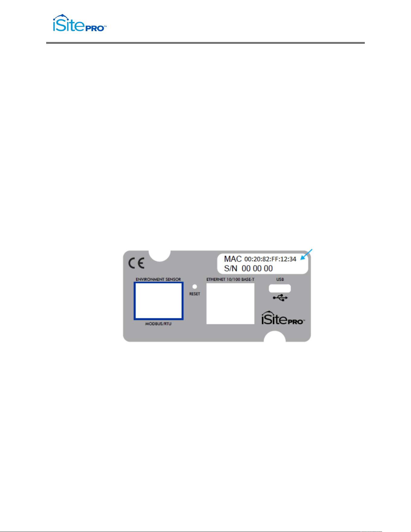
For example, if the MAC Address is 00:20:82:FF:12:34, the default
password would be Adm1nFF1234
b) Click “LOG IN” pushbutton
c) By default, the admin user will have full access to the iSite PRO UI.
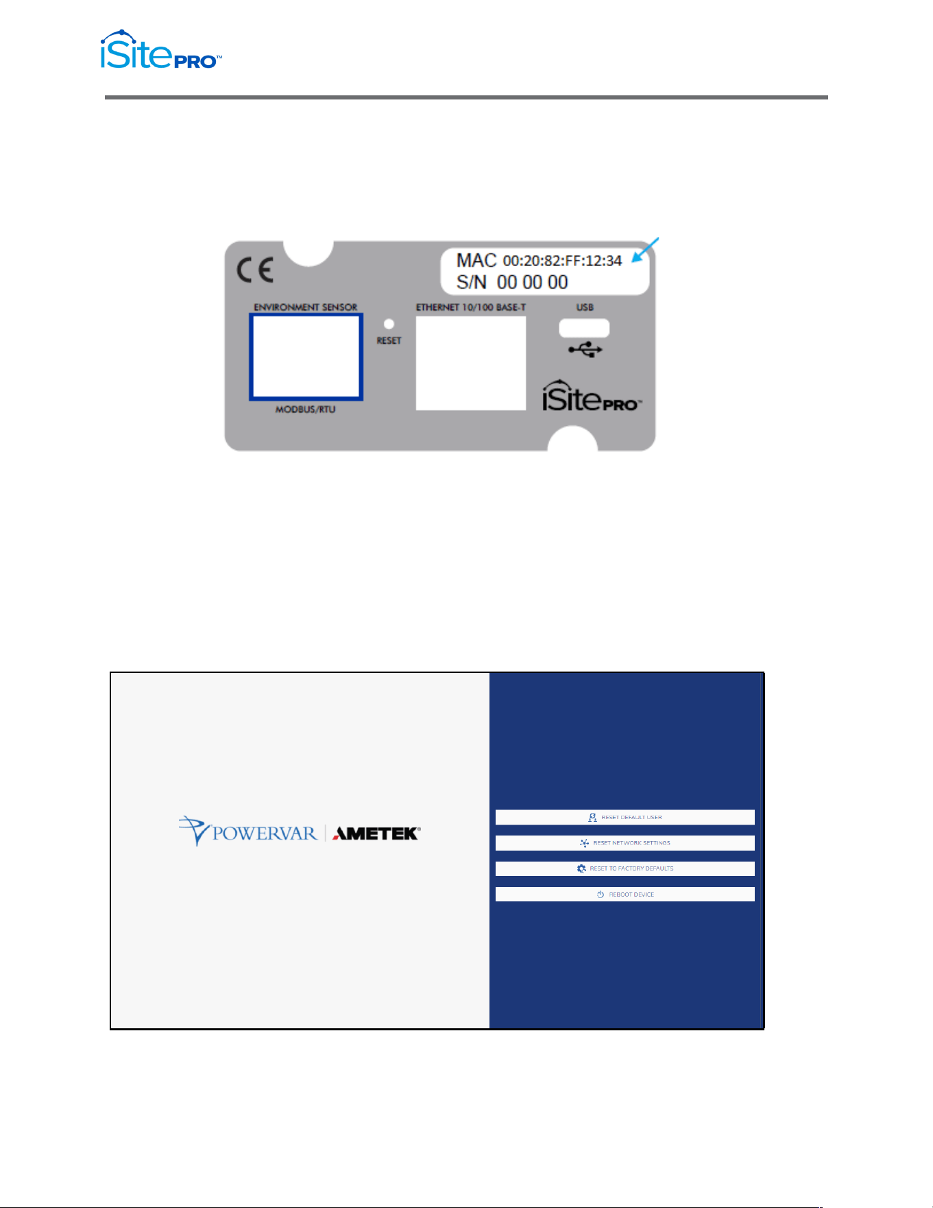
2.2.3 Finding MAC Address of iSite PRO
Reference the MAC address label above the ethernet port on the iSite
PRO.

10
Network Adapter for UPS Management User Manual
© 2021 AMETEK, Inc. / Technical Support: 1-800-645-9721 / surgex.com
3.0
Web
3.1
Interface Navigation
Overview
The Web user interface (UI) provides options to manage the UPS and the iSite
PRO and to view the status of the UPS. This interface is available over HTTP or
HTTPS based on the network configuration.
3.2
Supported Web Browsers
The iSite PRO Web interface is compatible with the following browsers:
•
The latest release of Microsoft® Edge®
•
The latest release of or Google® Chrome®
•
The latest releases of Mozilla® Firefox®
•
Other commonly available browsers might work but have not been fully
tested.
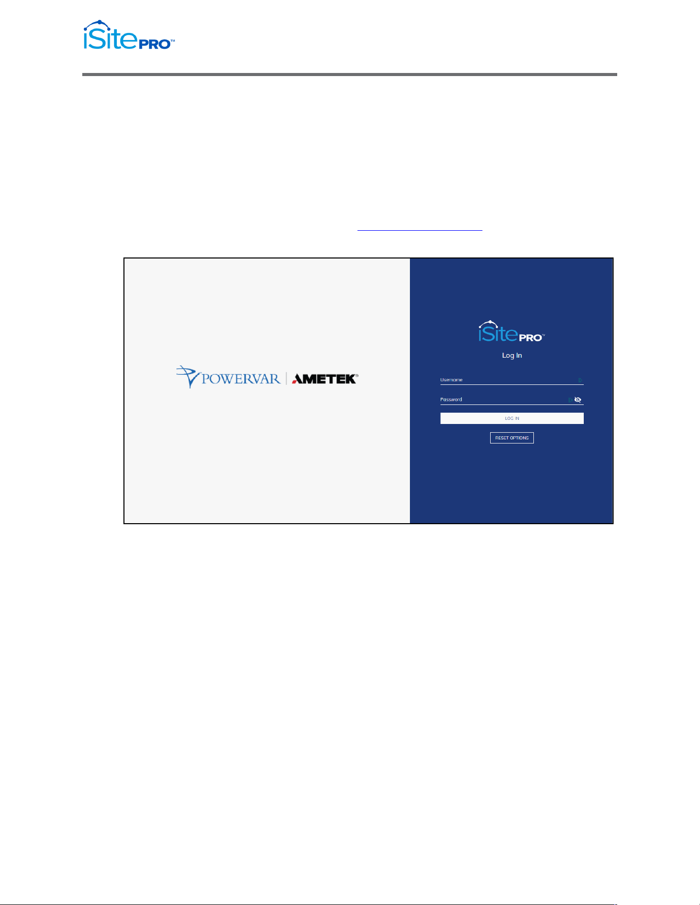
3.3 Logging On
You can use the DNS name or the System IP address of the iSite PRO as the
URL address. Use your case-sensitive username and password to log on. The
default username is admin and the default password is in the format of
Adm1nXXXXXX, where XXXXXX are the last 6 digits of the device MAC address.
11
Network Adapter for UPS Management User Manual
© 2021 AMETEK, Inc. / Technical Support: 1-800-645-9721 / surgex.com
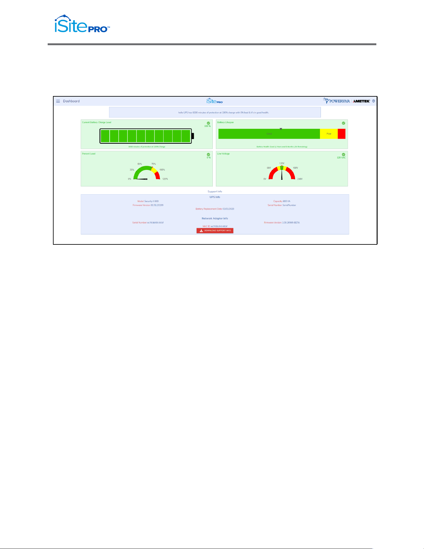
3.4 Dashboard
The Dashboard page provides the overall status of the UPS.
3.4.1 UPS Status Window
This window provides real-time information of the UPS. This
information includes UPS Health Status and Event Alarms.
3.4.2 Current Battery Charge Level
This icon displays the real-time current battery charge level.
3.4.3 Battery Lifespan
This graph represents the real-time battery lifespan (years and
months)
3.4.4 Support Info
This section provides hardware information of the UPS and the
iSite PRO.
3.4.5 Download Support Info
Pressing this button will download a compressed file (.zip) that
represents a snapshot of the current status of the UPS. This file
can be sent to technical support for further analysis.
3.4.6 Line Voltage (Volts)
This meter displays the real-time Line Voltage to the UPS
3.4.7 Percent Load
This meter represents the real-time Percent Load of the UPS
12
Network Adapter for UPS Management User Manual
© 2021 AMETEK, Inc. / Technical Support: 1-800-645-9721 / surgex.com
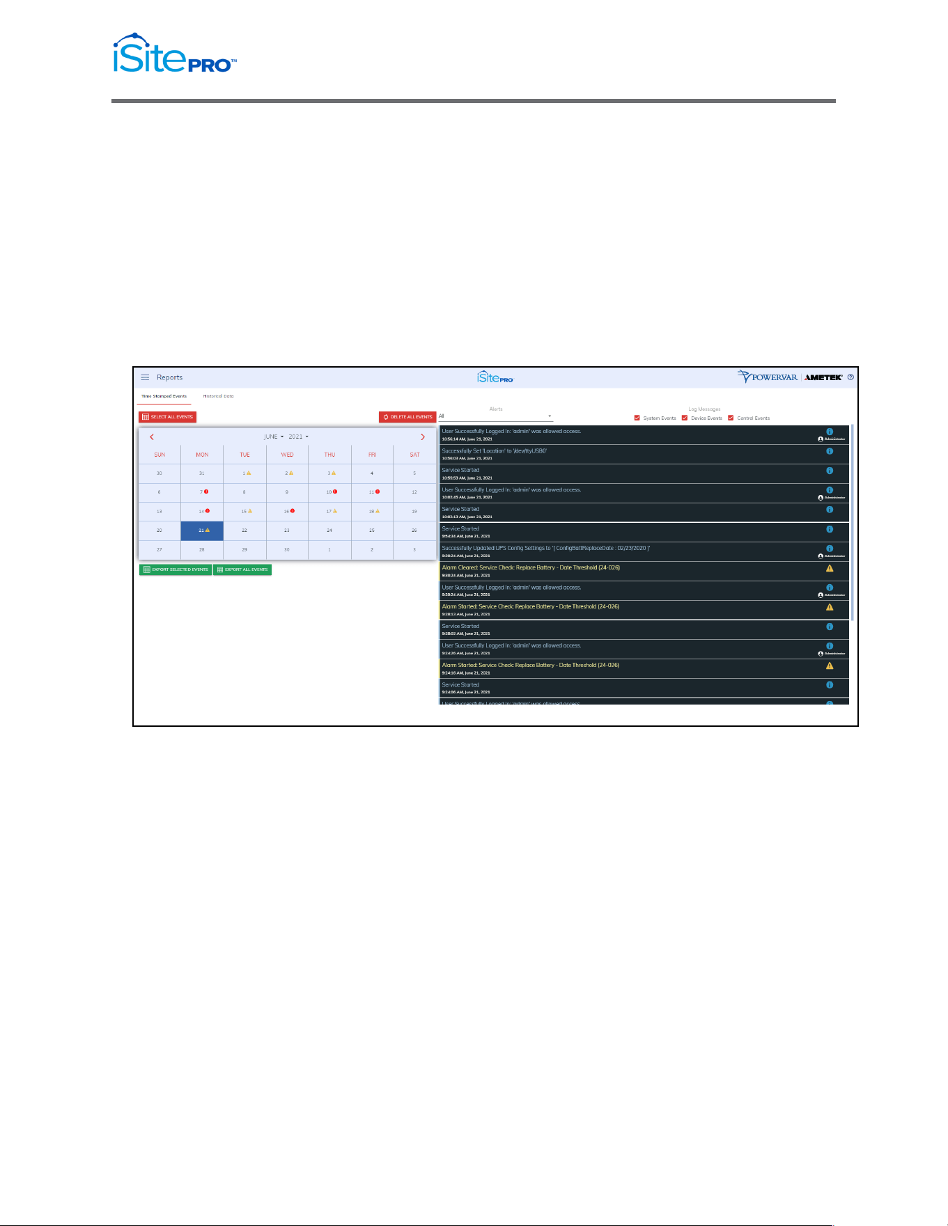
3.5 Reports
The Reports page displays data collected by the adapter and stored to its internal
memory. The data is presented in two groups: Time Stamped Events and
Historical Data.
3.5.1 Time Stamped Events
Time Stamped Events are system or device events recorded with a date
and time of occurrence. The adapter must be configured to synch with an
NTP server for accurate time stamps. Events can be filtered by System,
Device or Control types.
13
Network Adapter for UPS Management User Manual
© 2021 AMETEK, Inc. / Technical Support: 1-800-645-9721 / surgex.com
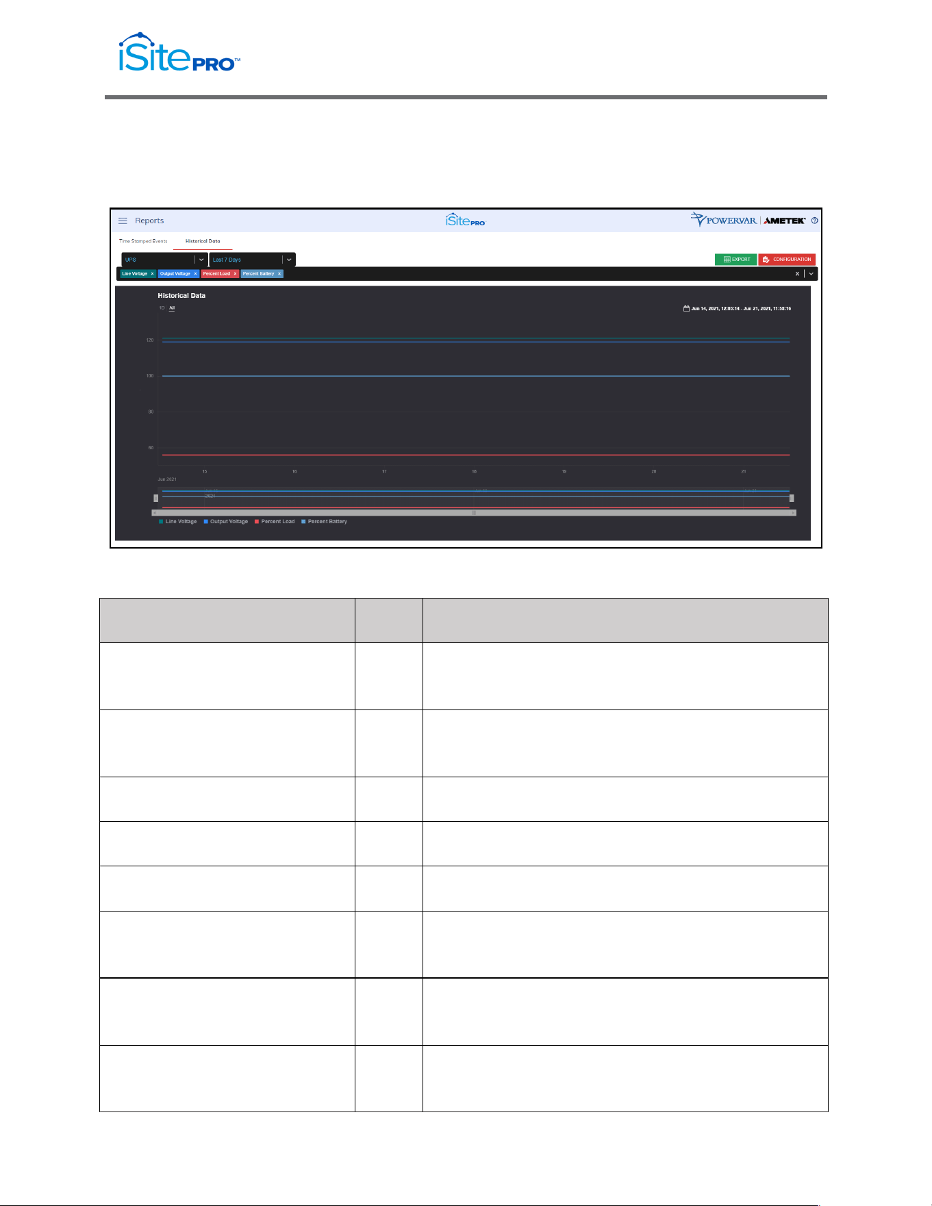
3.5.2 Historical Data
Historical Data is a record of measured electrical parameters and may be
adjusted to sample certain items at specific intervals.
The available parameters are:
Historical Parameter
Units
Description
Battery Voltage
VDC
The DC Voltage measured at the battery or charger
output.
Line Frequency
Hz.
The measurement of frequency of AC voltage on the
input of the UPS.
Line Voltage
VAC
The measured AC line voltage.
Line Voltage Minimum
VAC
The minimum measured AC line voltage.
Line Voltage Maximum
VAC
The maximum measured AC line voltage.
Line Voltage – Log Period
Minimum
VAC
The minimum line voltage recorded during the
period since the last log entry was made.
Line Voltage – Log Period
Maximum
VAC
The maximum line voltage recorded during the
period since the last log entry was made.
Line Voltage – Log Period
Average
VAC
The average line voltage recorded during the period
since the last log entry was made.
14
Network Adapter for UPS Management User Manual
© 2021 AMETEK, Inc. / Technical Support: 1-800-645-9721 / surgex.com
Output Voltage
VAC
The measured UPS output voltage.
Percent Battery
%
Current percentage of the remaining total battery
charge.
Percent Load
%
The percentage of the UPS capacity currently being
supplied by the UPS
Percent Load – Period
Minimum
%
The minimum percentage of the UPS capacity
recorded since the last log entry was made.
Percent Load – Period
Maximum
%
The maximum percentage of the UPS capacity
recorded since the last log entry was made.
Percent Load – Period Average
%
The average percentage of the UPS capacity
recorded since the last log entry was made.
Temperature
degC
The measurement of the temperature (degrees C)
reported by the UPS. Generally, the temperature
reported reflects a temperature reading within the
UPS cabinet - typically either in the inverter (power
electronics) region or in the battery compartment.
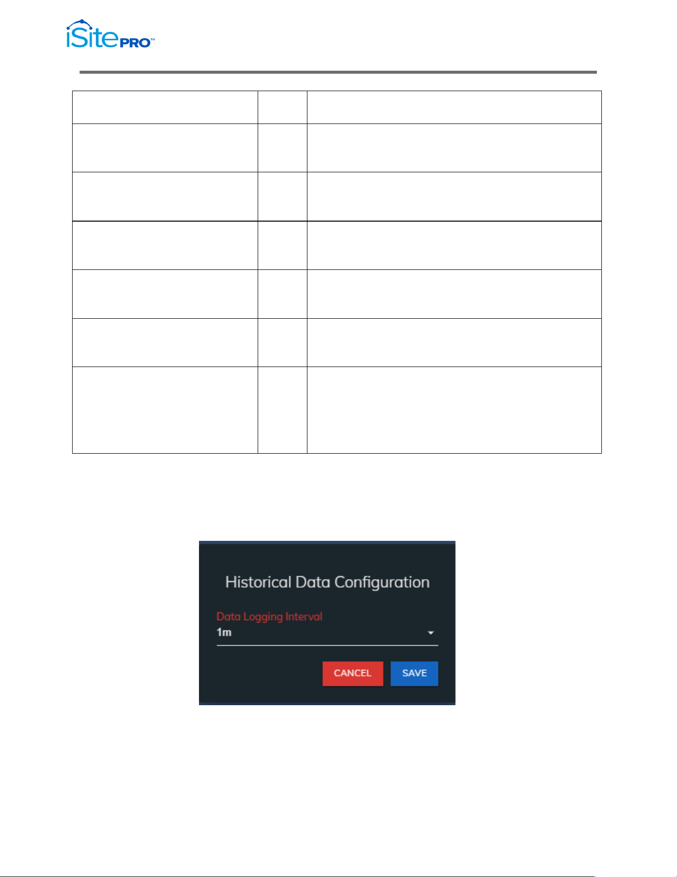
Configuration Button
Press this button to adjust the data logging interval. The default is to log
every 1 minute, which will allow for over 30 days of data.
15
Network Adapter for UPS Management User Manual
© 2021 AMETEK, Inc. / Technical Support: 1-800-645-9721 / surgex.com
3.6 UPS Settings
The UPS Settings page can be accessed by clicking on UPS Settings in the
menu. This page is divided into 5 tabs, which are described in this section.
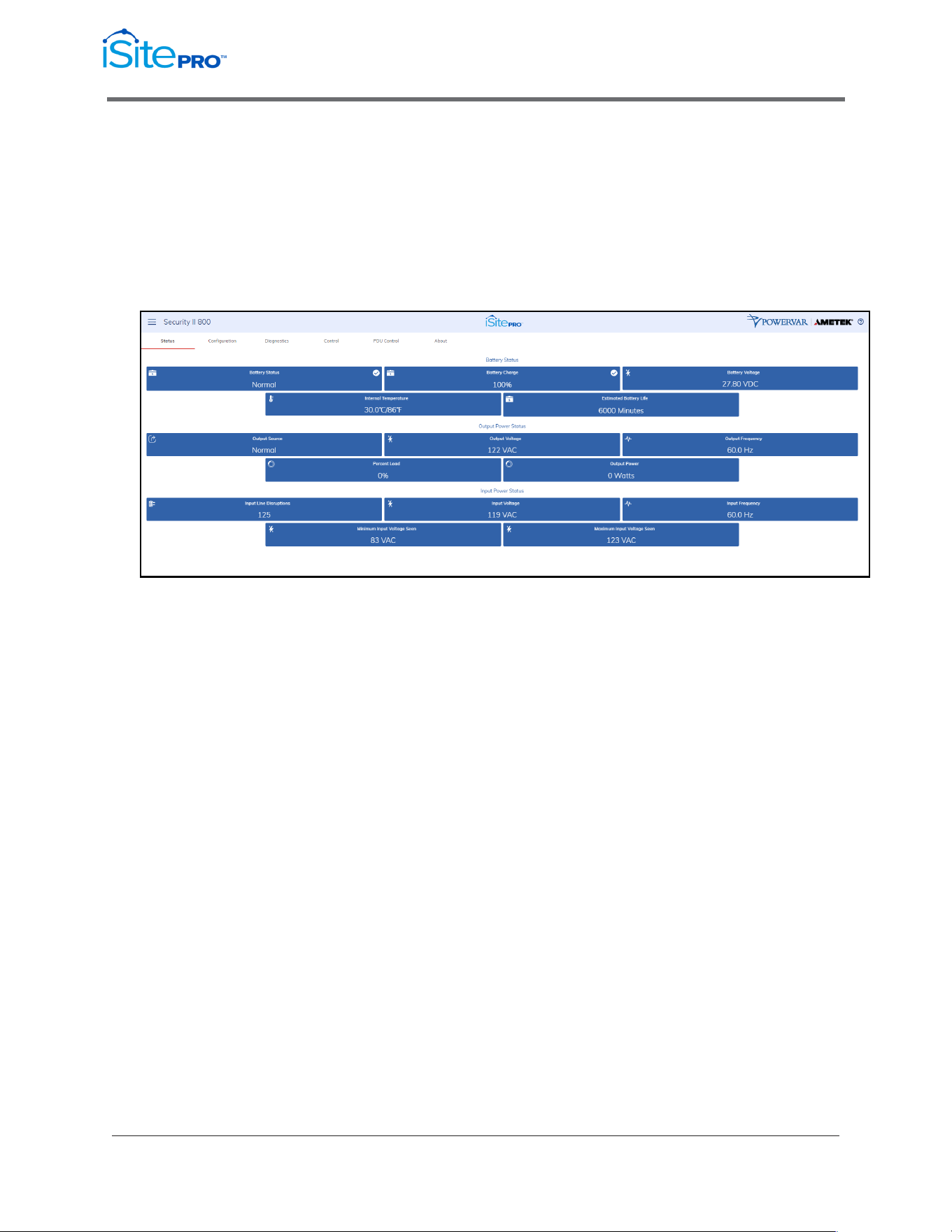
3.6.1 Status Tab
This tab displays the current UPS measurements and alarms. The
information on this tab will update approximately every 10 seconds.
•
Battery Status: States are Normal, Charging or Discharging. This
value is returned as the object: upsBatteryStatus in the UPS MIB -
RFC1628.
•
Battery Charge Remaining: Current percentage of the remaining
total battery charge. This value is returned as the object
upsBatteryChargeRemaining in the UPS MIB - RFC1628.
•
Battery Voltage: Voltage measured at the battery or charger
output. This may be reported as "string" voltage or "cell" voltage
depending on the UPS model. This value is returned as the
upsBatteryVoltage object in the UPS MIB - RFC1628.
•
Internal Temperature: The internal temperature reported by the
UPS. This value is returned as the upsBatteryTemperature object
in the UPS MIB - RFC1628.

16
Network Adapter for UPS Management User Manual
© 2021 AMETEK, Inc. / Technical Support: 1-800-645-9721 / surgex.com
•
Est. Battery Life: Sometimes referred to as Estimated Autonomy.
This is an estimate of the amount of time the UPS batteries can
sustain the current load. This value is continuously recalculated
based on the operating conditions of the UPS. When the UPS is
on battery, this value may decrease faster than expected due to
battery age and other variables that are difficult to model in the
calculation algorithm. This value is returned as the object;
upsBatteryEstimatedMinutesRemaining in the UPS MIB -
RFC1628.
•
UPS Up Time: The amount of time since the UPS was last
started. (This value is returned as the sysUpTime object in MIB-2).
•
Output Voltage: The measured UPS output voltage.
•
Output Source: The source of the UPS output power. Under
normal conditions this will be Utility. The source may also be
reported as Battery or Bypass.
•
Percent Load: The percentage of the UPS capacity currently
being supplied by the UPS.
•
Output Watts: The measured UPS output power in Watts.
•
ECO Mode: Indicates if ECO Mode is currently active or not
active. This will only appear on units with the ECO Mode feature.
•
Input Line Disruptions: The number of times the UPS has been
on inverter due to input voltage being out of tolerance.
•
Input Frequency: The frequency measured on the UPS AC input.
•
Input Voltage: The voltage measured at UPS AC input.
•
Min. Input Voltage Seen: The lowest input voltage detected by
the UPS since last reset. (See Also UPS Control to reset the
stored minimum input voltage to the current input voltage).
•
Max. Input Voltage Seen: The highest input voltage detected by
the UPS since last reset. (See Also UPS Control to reset the
stored maximum input voltage to the current input voltage)
17
Network Adapter for UPS Management User Manual
© 2021 AMETEK, Inc. / Technical Support: 1-800-645-9721 / surgex.com
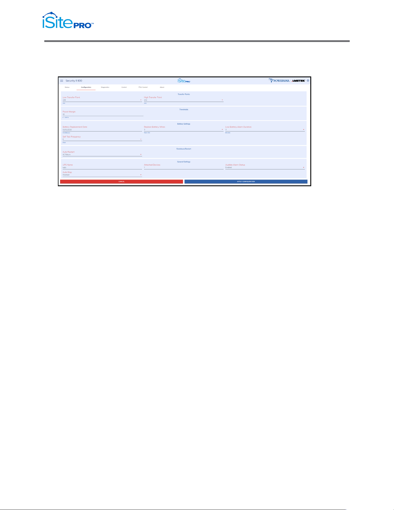
3.6.2 Configuration Tab
This tab is used to configure various UPS settings.
NOTE: Your UPS may not support all the configuration options listed in
this document.
•
Temperature Threshold: The maximum internal UPS
temperature allowed before triggering a UPS over temperature
alarm.
•
Overload Threshold: The maximum percent load allowed before
triggering a UPS overload alarm.
•
Power Margin Threshold: The maximum percent load allowed
before triggering a Power Margin Exceeded Alarm.
•
Low/High Transfer Point: The transfer points determine the
range of acceptable output voltage values. If the input line
voltage drops below the lower transfer point or rises above the
upper transfer point, the UPS takes corrective action either by
using the booster or switching to battery power. The proper
setting of transfer points depends on the voltage tolerance of the
devices connected to the UPS. Setting the transfer points closer
together will cause the UPS to provide a more tightly controlled
voltage but may also cause the UPS to switch to battery power
more frequently, depending on the quality of your AC line power.
The factory default values are sufficient for most applications.
•
Battery Replacement Date: The date on which the UPS was first
commissioned or when the battery was last replaced. This value
will be set automatically the first time iSite PRO boots up and
retrieves a valid date from a network time (NTP) server. The
assumption is that the iSite PRO is installed at about the same
time the UPS is first installed and commissioned. It is up to the
user to set this date to a more accurate commissioning date and
to maintain the date when batteries are replaced in the future.

18
Network Adapter for UPS Management User Manual
© 2021 AMETEK, Inc. / Technical Support: 1-800-645-9721 / surgex.com
•
Replace Battery When: Counts elapsed time from the value in
the Battery Replacement Date field. Low Battery Alarm Duration:
Low Battery Alarm Duration: Triggers the UPS Low Battery alarm
when estimated minutes remaining -- as computed by the UPS.
•
Low Battery Alarm Duration: Triggers the UPS Low Battery
alarm when estimated minutes remaining -- as computed by the
UPS or limited by the Authorized Autonomy setting -- reaches this
value.
•
Shutdown Type: This setting controls the behavior of the UPS
when a shutdown command is received from monitoring software.
If "Whole UPS" is selected, the UPS output and internal
electronics are turned off. In this state, the UPS will not be able to
communicate with monitoring software until the UPS is restarted.
If "Output Only" is selected, the UPS output is turned off, but the
UPS internal electronics remain on.
•
Auto Restart: This setting controls the conditions under which
UPS output is restarted after the UPS has been shut down. If "AC
Return" is selected, UPS output is automatically restarted when
AC line power is restored. If "Manual Return" is selected, UPS
output must be restarted manually, either by turning the UPS
power switch off, and then on, or by issuing a command on the
serial port of the UPS.
•
UPS Name: The name of this UPS. (This value will be returned as
upsIdentName object in the SNMP UPS MIB - RFC1628).
•
Attached Devices: A description of the devices attached to the
UPS. (This value will be returned as upsIdentAttachedDevices
object in the SNMP UPS MIB - RFC1628).
•
Audible Alarm: Controls audible alarms that the UPS may initiate
during tests or alarm conditions. You can use this control to
silence audible alarms that might sound when a UPS test is
initiated. (The control is the upsConfigAudibleStatus object in
SNMP UPS MIB - RFC1628).
•
Auto Stop: Sets the AutoStop control in some UPS’ that cause
the UPS to turn off after some time with no measurable load
present.
19
Network Adapter for UPS Management User Manual
© 2021 AMETEK, Inc. / Technical Support: 1-800-645-9721 / surgex.com
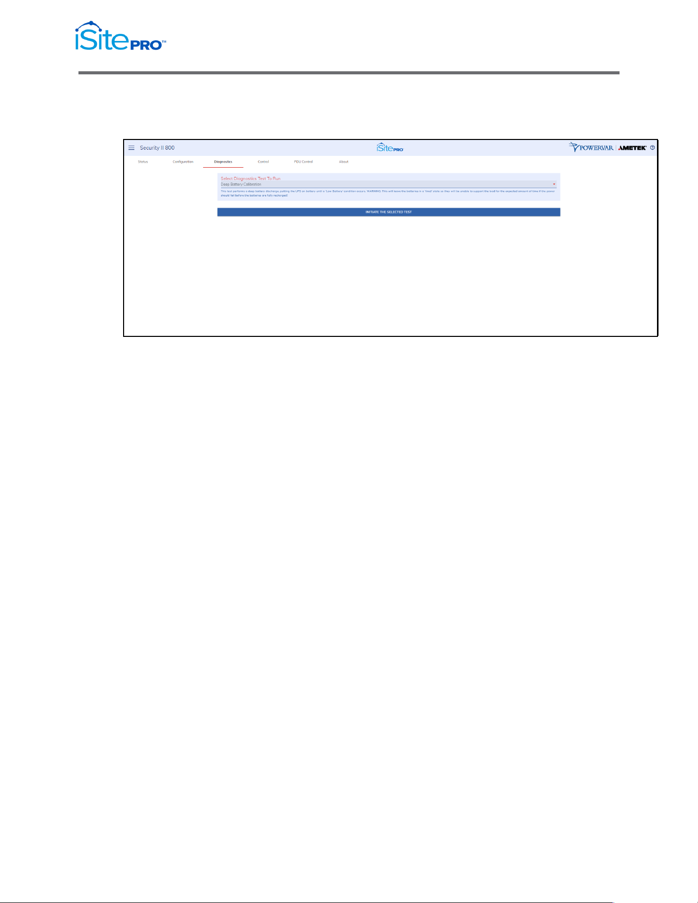
3.6.3 Diagnostics Tab
This tab is used to initiate a UPS Diagnostics test.
NOTE:
•
Your UPS may not support all the test options listed in this
section.
•
Your UPS may need to recharge its batteries after a battery test is
complete. Your UPS may refuse to initiate a battery test if the
battery is recovering from a previous test or if some other
condition exists that would invalidate the results.
•
Select a test from the list box. To start the test, click the button:
"Initiate Selected Test".
Battery Run Test: This test causes the UPS to run on battery power for a
specified amount of time. After the specified amount of time, the UPS will
switch back to AC line power.
Quick Battery Test: This test performs a qualitative analysis of the
condition of the battery. This test runs at regular intervals. The impedance
test returns one of three results; Passed, Battery is significantly degraded,
or the battery is defective and must be replaced as soon as possible.
Deep Battery Calibration: This test performs a deep battery discharge,
putting the UPS on battery until a "Low Battery" condition occurs.
WARNING: This will leave the batteries in a "tired" state so they will be
unable to support the load for the expected amount of time if AC input
power should fail before the batteries are fully recharged!

20
Network Adapter for UPS Management User Manual
© 2021 AMETEK, Inc. / Technical Support: 1-800-645-9721 / surgex.com
3.6.4 Control Tab
This tab is used to perform various UPS control functions.
Select one of the control commands by selected it from the list box. Click
the "Execute the Selected Command" button to execute the command.
NOTE: Your UPS may not support all of the options listed here
•
Reset the Min/Max Measured Voltage Seen: A record of the
Minimum and Maximum input line voltages are stored in your
UPS.
•
Mute the Audible Alarm: This action mutes the audible alarm for
the duration of the current event. It does not disable the alarm. If
you want to silence the audible alarm for future events, navigate to
the UPS Configuration menu. The control for the audible alarm is
in the General Settings dialog area.
•
Turn UPS Output On: This action causes the UPS output to
immediately turn on.
•
Turn UPS Output Off: This action causes the UPS output to
immediately turn off.
WARNING: All loads connected to this UPS will be turned off.
•
Reboot the UPS: This action causes the UPS output to
immediately turn off and then restart after the time specified.
WARNING: When you initiate the reboot control, all loads connected to
this UPS will lose power and will turn back on when the UPS output is re-
energized. Make sure this is what you want to do before you initiate this
control!
NOTE: This command is not active on 3-phase UPS.
21
Network Adapter for UPS Management User Manual
© 2021 AMETEK, Inc. / Technical Support: 1-800-645-9721 / surgex.com
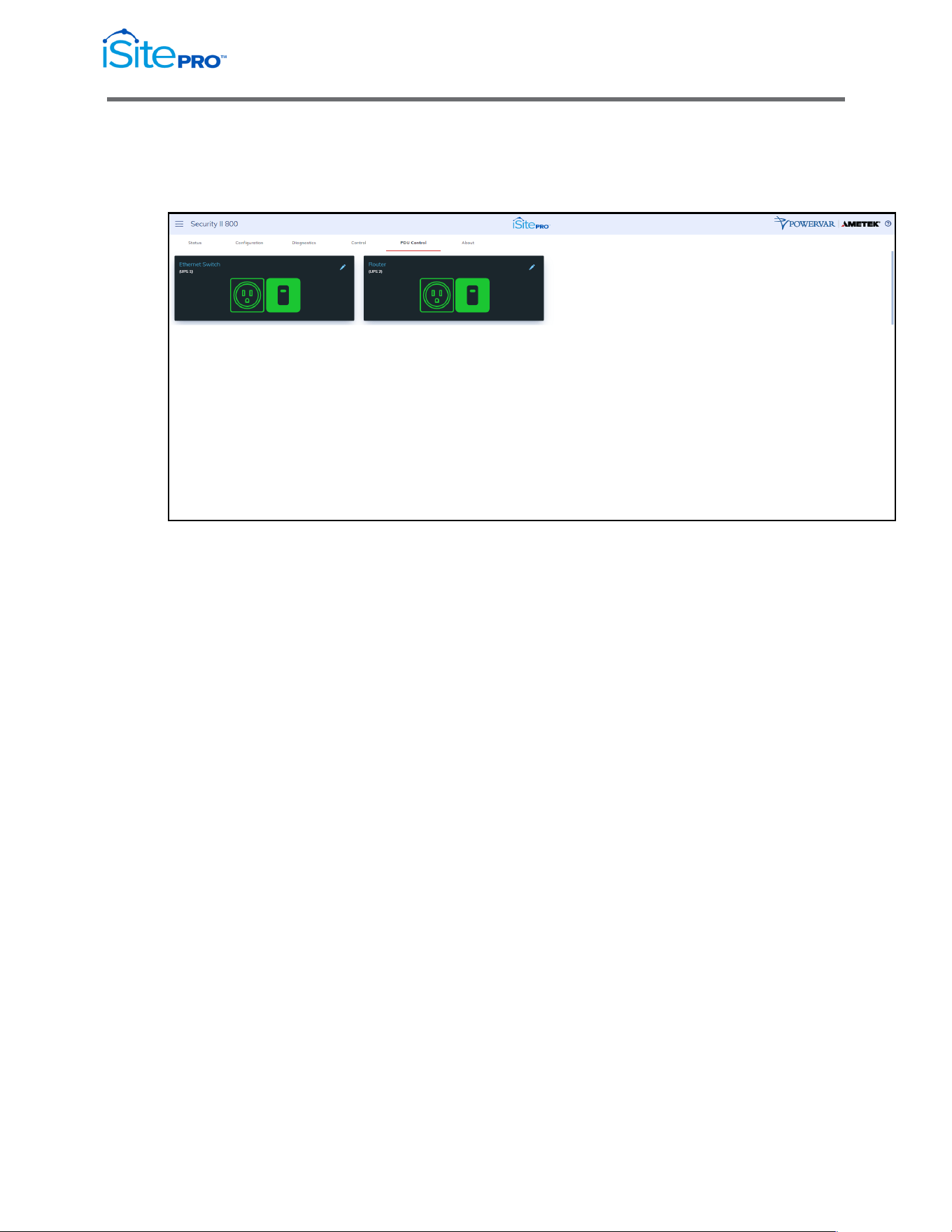
3.6.5 PDU Control Tab
This tab can be used to control and configure the UPS’s Programmable
Outlets.
The current state of the outlet is indicated by the state of the switch
graphic, and the graphic color. If the switch position is up, and the color is
green, then the outlet is currently on. If the switch position is down, and
the color is red, then the outlet is currently off.
Clicking on the switch will toggle the state of each outlet. You will be
presented with a confirmation dialog before the action is taken.
WARNING When you turn off an outlet, all loads connected to that outlet
will turn off.
22
Network Adapter for UPS Management User Manual
© 2021 AMETEK, Inc. / Technical Support: 1-800-645-9721 / surgex.com
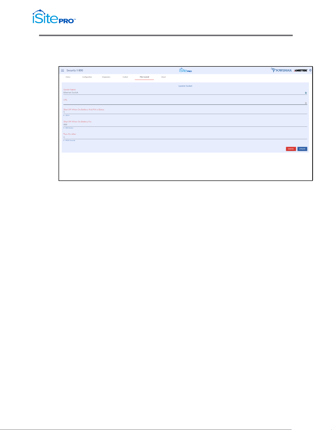
3.6.6 PDU Configuration Screen
Access this screen by clicking on the edit icon on the PDU control screen.
•
Socket Name: A descriptive name of the device(s) connected to
the outlet.
•
URL: The URL of the device connected to the outlet.
•
Shut Off When On Battery And Pct is Below: The percent
battery at which to turn this outlet off when the UPS is running on
battery.
•
Shut Off When On Battery For: The amount of time after the
UPS starts running on battery power, to turn this outlet off.
•
Turn On After: The amount of time to wait to turn this outlet back
on following a power outage.
23
Network Adapter for UPS Management User Manual
© 2021 AMETEK, Inc. / Technical Support: 1-800-645-9721 / surgex.com
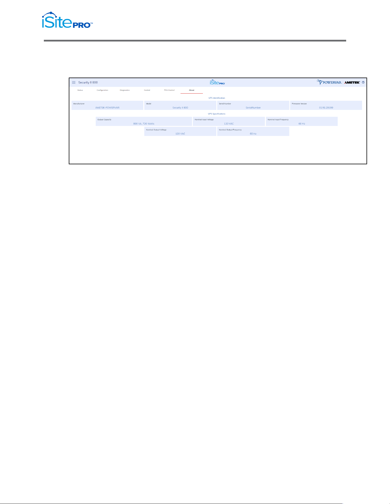
3.6.7 About Tab
This tab displays the identity and nominal ratings of the UPS.
•
Model: The model number of the UPS unit.
•
Serial Number: The serial number of the UPS unit.
•
Firmware Version: The version number of the firmware in the
UPS.
•
Capacity: The maximum power output of the UPS. Capacity is
measured in VA and Watts. The VA measurement is the
maximum power available to drive devices with switched-mode
power supplies such as computers. The Watts measurement is
the maximum power available to drive resistive loads such as
lighting or devices with motors.
•
Nominal Input Voltage: The line voltage that the UPS is
designed to operate with.
•
Nominal Input Frequency: The line frequency that the UPS is
designed to operate with.
•
Nominal Output Voltage: The nominal output voltage supplied by
the UPS.
•
Nominal Output Frequency: The nominal frequency that
supplied by the UPS.
24
Network Adapter for UPS Management User Manual
© 2021 AMETEK, Inc. / Technical Support: 1-800-645-9721 / surgex.com
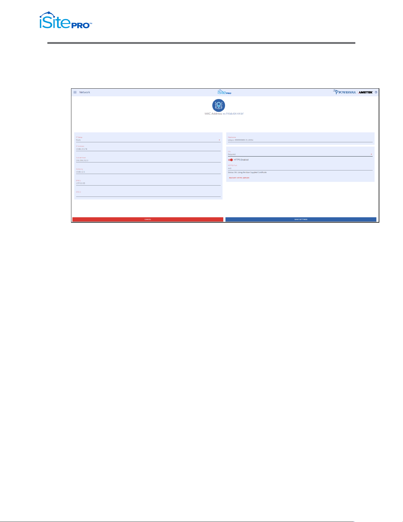
3.7 Network Screen
This screen enables the user to configure the network settings of the iSite PRO.
•
IP Setup: Specifies if the device will have a static IP Address, or
will dynamically be assigned network settings through DHCP.
•
IP Address: Current IP Address of the network interface on the
RJ45 Ethernet port.
•
Subnet Mask: Current Subnet Mask of the network interface on
the RJ45 Ethernet port.
•
Gateway: Current Gateway of the network interface on the RJ45
Ethernet port.
•
DNS 1: Current configured primary DNS of the network interface
on the RJ45 Ethernet port.
•
DNS 2: Currently configured secondary DNS of the network
interface on the RJ45 Ethernet port.
•
Hostname: A configurable unique name to be used to access the
device instead of an IP Address.
•
SSL: Specifies whether the web server will be SSL encrypted
(HTTPS) or not (HTTP). The default certificate is self-signed and
will require the user continue through a safety notification if a
custom signed certificate is not uploaded to the device.
25
Network Adapter for UPS Management User Manual
© 2021 AMETEK, Inc. / Technical Support: 1-800-645-9721 / surgex.com
•
HTTP Enabled: Specifies if the web server is enabled or disabled.
•
NOTE: If disabling the web server, the web interface and REST
API will be disabled, only limited functionality over SNMP will
remain if enabled.
•
HTTP Port: Port number to use for the web server.
Status: This will provide the status of the server. If using HTTPS,
this will provide information regarding which SSL Key/Certificate is
being used. If the key/certificate files were uploaded by the user, it
will indicate if they are valid. If they are not valid, the default
key/certificate will be used.
Use the “RESTART HTTP(S) SERVER” Button to restart the
server if new key/certificate files have been uploaded using the
Utilities Screen. This will cause the current page to reload.
•
The Cancel button will reset all fields to their initial value.
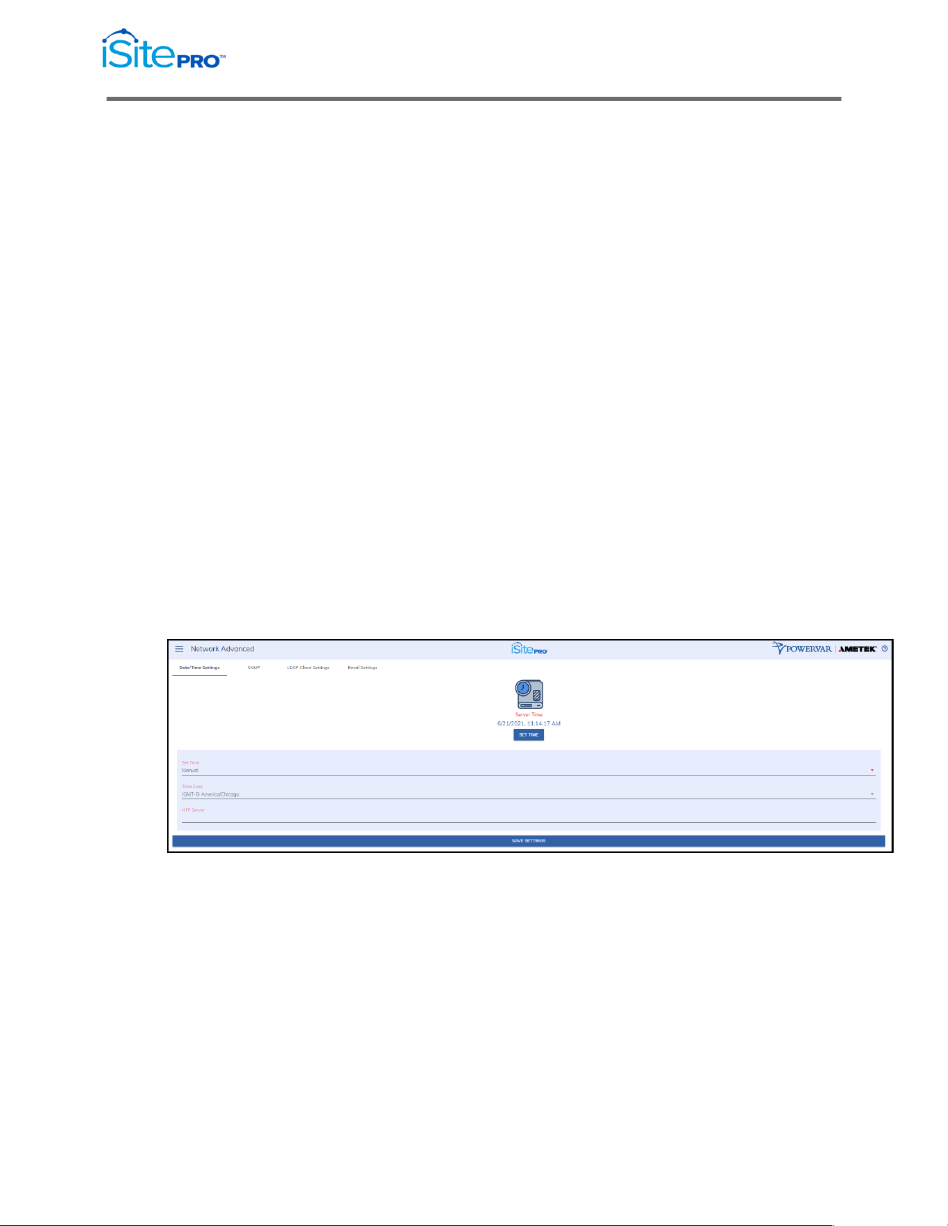
3.8 Network Advanced Screen
This screen enables the user to configure the network settings of the iSite PRO.
3.8.1 Date/Time Settings Tab
This tab allows the configuration of the date and time of the iSite PRO.
•
Server Time: Displays the device’s internal time based on the
configured time zone.
•
Set Time: Specifies the method for setting the time in the iSite
PRO. Options for this setting are NTP or manual. NTP will use the
NTP Server option to automatically sync the device time every
day.
•
Time Zone: Specifies the desired time zone adjustment for the
Squid device.
•
NTP Server: Specifies the hostname or IP address of the NTP
server to use for time synchronization.
26
Network Adapter for UPS Management User Manual
© 2021 AMETEK, Inc. / Technical Support: 1-800-645-9721 / surgex.com
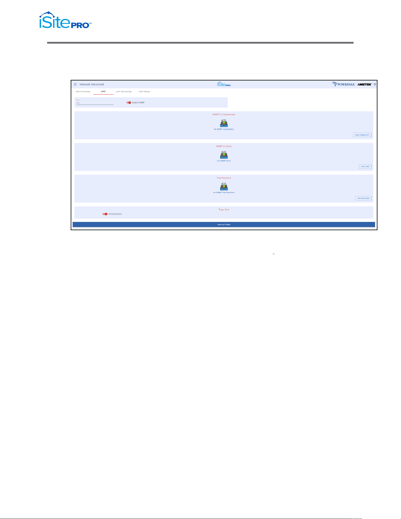
3.8.2 SNMP Tab
This tab allows the configuration of the SNMP functionality of the iSite PRO.
The SNMP agent in the iSite PRO conforms to the SNMP UPS MIB (RFC1628).
This MIB was originally circulated in SNMPv2 syntax. .
SNMP V1 Communities
SNMP V1 Communities is an authentication scheme that enables an intelligent
network device to validate SNMP requests.
Name: The name of an SNMP access community (i.e. "public" or "private").
NOTE: Blank spaces are not accepted within the name string.
Source: The IP address/mask of allowed stations.
A subnet range can be specified using the IP/MASK or IP/BITS syntax as shown
below. This can be specified as IP/MASK or IP/BITS.
10.5.2.0/[bit mask integer] = allow all address in the specific range that passes
through the mask.
Examples:
10.5.2.0/8 = 10.0.0.1 thru 10.255.255.254
10.5.2.0/16 = 10.5.0.1 thru 10.5.255.254
10.5.2.0/20 = 10.5.0.1 thru 10.5.15.254
10.5.2.0/24 = 10.5.2.1 thru 10.5.2.254
10.5.2.0/26 = 10.5.2.1 thru 10.5.2.62
10.5.2.0/32 = same as no mask, 10.5.2.0
Access: Enable Read Only or Read/Write access for individual communities

27
Network Adapter for UPS Management User Manual
© 2021 AMETEK, Inc. / Technical Support: 1-800-645-9721 / surgex.com
SNMP V3 Users
In contrast to SNMP version 1 (SNMPv1) and SNMP version 2
(SNMPv2), SNMP version 3 (SNMPv3) supports authentication and
encryption.
SNMPv3 uses the user-based security model (USM) for message security
and encryption.
The iSite PRO supports MD5 and DES encryption.
Username: The name of an SNMPv3 user.
Authorization: The only option is MD5/DES.
Passphrase: The Passphrase used for MD5 and DES authentication and
privacy.
Access: Choose Read Only or Read Write access for each user.
Trap Receivers
Community: The community (authentication string) of the SNMP trap
receiver community
Destination Address: The IP address of the trap receiver.
Port: The port used by the trap receiver. Typically, this is 162.
Traps Sent
Send Authentication Traps: Enables or disables the agent to send
SNMP authentication traps.

28
Network Adapter for UPS Management User Manual
© 2021 AMETEK, Inc. / Technical Support: 1-800-645-9721 / surgex.com
About UPS Traps
There are four traps defined in the standard UPS MIB (RFC1628):
Trap1: upsTrapOnBattery
DESCRIPTION: "The UPS is operating on battery power. This trap is persistent
and is resent at one-minute intervals until the UPS either turns off or is no longer
running on battery."
Trap2: upsTrapTestCompleted NOTIFICATION-TYPE
DESCRIPTION: "This trap is sent upon completion of a UPS diagnostic test."
Trap3: upsTrapAlarmEntryAdded NOTIFICATION-TYPE
DESCRIPTION: "This trap is sent each time an alarm is inserted into to the alarm
table. It is sent on the insertion of all alarms except for upsAlarmOnBattery and
upsAlarmTestInProgress covered in Traps 1 and 2.“
Trap4: upsTrapAlarmEntryRemoved NOTIFICATION-TYPE
DESCRIPTION: "This trap is sent each time an alarm is removed from the alarm
table. It is sent on the removal of all alarms except for upsAlarmTestInProgress."
WELL KNOWN ALARMS: (1-24)
Content sent in Traps 3 and 4 include a numeric identity (upsAlarmId) of
the specific alarm that has been added or removed from the table. The
MIB defines 24 specific upsWellKnownAlarms.
Value=1.3.6.1.2.1.33.1.6.3.x
Where; x is the alarm identification number of the specific alarm entry.
ADDITIONAL ALARMS: (25-31)
In addition to the 24 wellKnownAlarms defined in RFC1628, the adapter
will also send additional alarms not defined in the MIB.
29
Network Adapter for UPS Management User Manual
© 2021 AMETEK, Inc. / Technical Support: 1-800-645-9721 / surgex.com
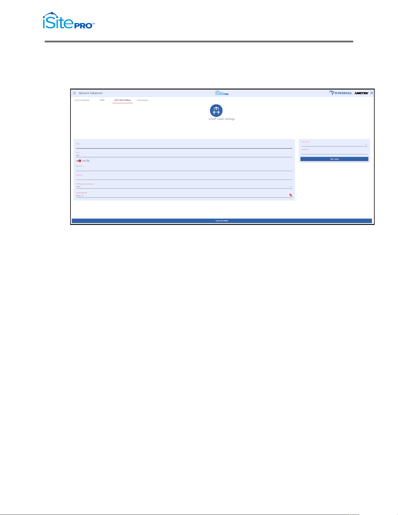
3.8.3 LDAP Client Settings
This form is used to configure the settings used by the LDAP client to
authenticate with an LDAP server.
The following information can be configured on this page:
•
Host: The IP address or name of the LDAP server
•
Port: The listening port used by the LDAP server, for non-secure
connections this is usually 389, for secure connections this is
usually 636. If using a secure connection, then check the LDAPS
option.
•
Base DN: This is the base DN of the server. (i.e.
dc=AMETEK,dc=com)
•
User DN: The User DN used to bind to the LDAP server and
authenticate the user. (i.e.
uid=%UserName,dc=AMETEK,dc=com)
•
There are 2 macros available when authenticating to the LDAP
server. They are:
•
%UserName% - This will be replaced by the username when
authenticating to the LDAP server.
•
%FullName% - This will be replaced by the user’s name when
authenticating to the LDAP server.

30
Network Adapter for UPS Management User Manual
© 2021 AMETEK, Inc. / Technical Support: 1-800-645-9721 / surgex.com
•
TLS Require Certificate: This is optional, based on the LDAP
server requirements. The options are Never, Hard, Demand, Allow
and Try.
•
Certificate File: This is optional based on the LDAP server
requirements. Upload the certificate file to the iSite PRO.LDAP
Client.
•
The LDAP Client page can be accessed by clicking on LDAP
Client Settings in the menu. This page contains 2 forms which can
be used to configure and test the LDAP client settings and
functionality.
•
Test LDAP Client
Use this form to test your LDAP client configuration. Select a user
from the list and enter the LDAP passcode for this user and press
the Perform Test button.
31
Network Adapter for UPS Management User Manual
© 2021 AMETEK, Inc. / Technical Support: 1-800-645-9721 / surgex.com
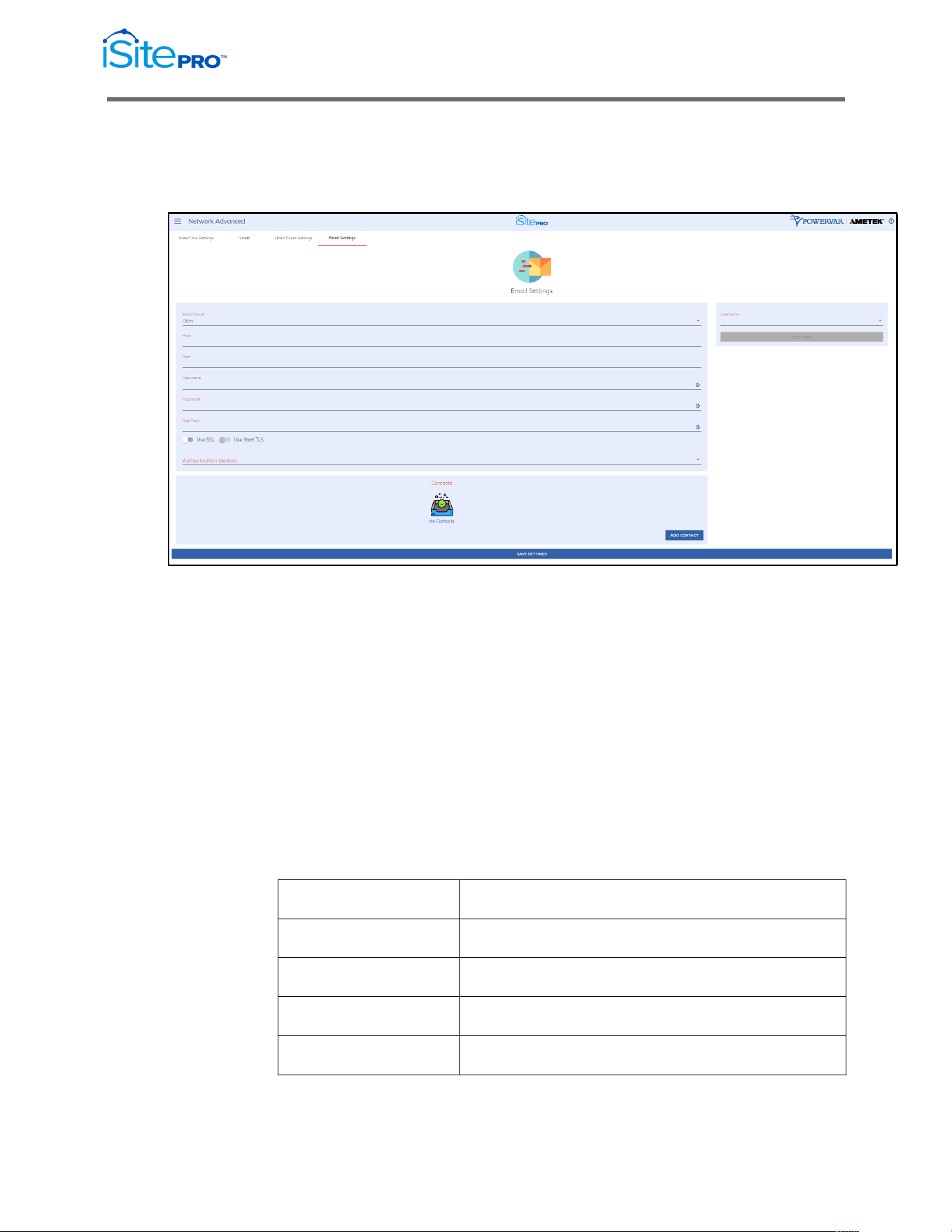
3.8.4 Email Settings
The Email Settings page can be accessed by clicking on Email Settings
tab of the Advanced Networking page.
Secure SMTP Settings
The following settings can be configured for send email using Gmail,
Office 365 or any other secure or non-secure SMTP server.
Email Server: Select the type of email server to use. The options are
Gmail, Office 365 or other. The Gmail and Office 365 options should be
used if you are using the Secure SMTP service provided by one of these
services. Select Other if you are using your own SMTP server or another
service.
Host: The host name or IP address of the SMTP server
Port: The port number used by the SMTP server. Typical SMTP Port
numbers are listed below.
Port Number
Description
25
Standard non-secure port
465
Deprecated port for secure SMTP
587
Modern port used for secure SMTP
2525
Alternative, non-standard SMTP port
32
Network Adapter for UPS Management User Manual
© 2021 AMETEK, Inc. / Technical Support: 1-800-645-9721 / surgex.com
•
Username: The username used for authentication on the SMTP
server
•
Password: The password used for authentication on the SMTP
server.
•
Mail From: The mail from address used on outgoing email
messages.
NOTE: This is ignored when using Internet services such as
Gmail, in this case the From address is the primary email address
for the user.
•
SSL/TLS Options: Enable Use SSL and/or Use Start TLS toggle
switches to enable the appropriate secure protocol to use.
•
Authentication Method – Select PLAIN or CRAM-MD5
authentication methods.
•
Contacts
•
This allows for a list of email recipients, other that users to receive
email messages based on alarm severity.
•
Send a Test Email
•
Use to this to test your configuration. A valid email address must
be supplied.
•
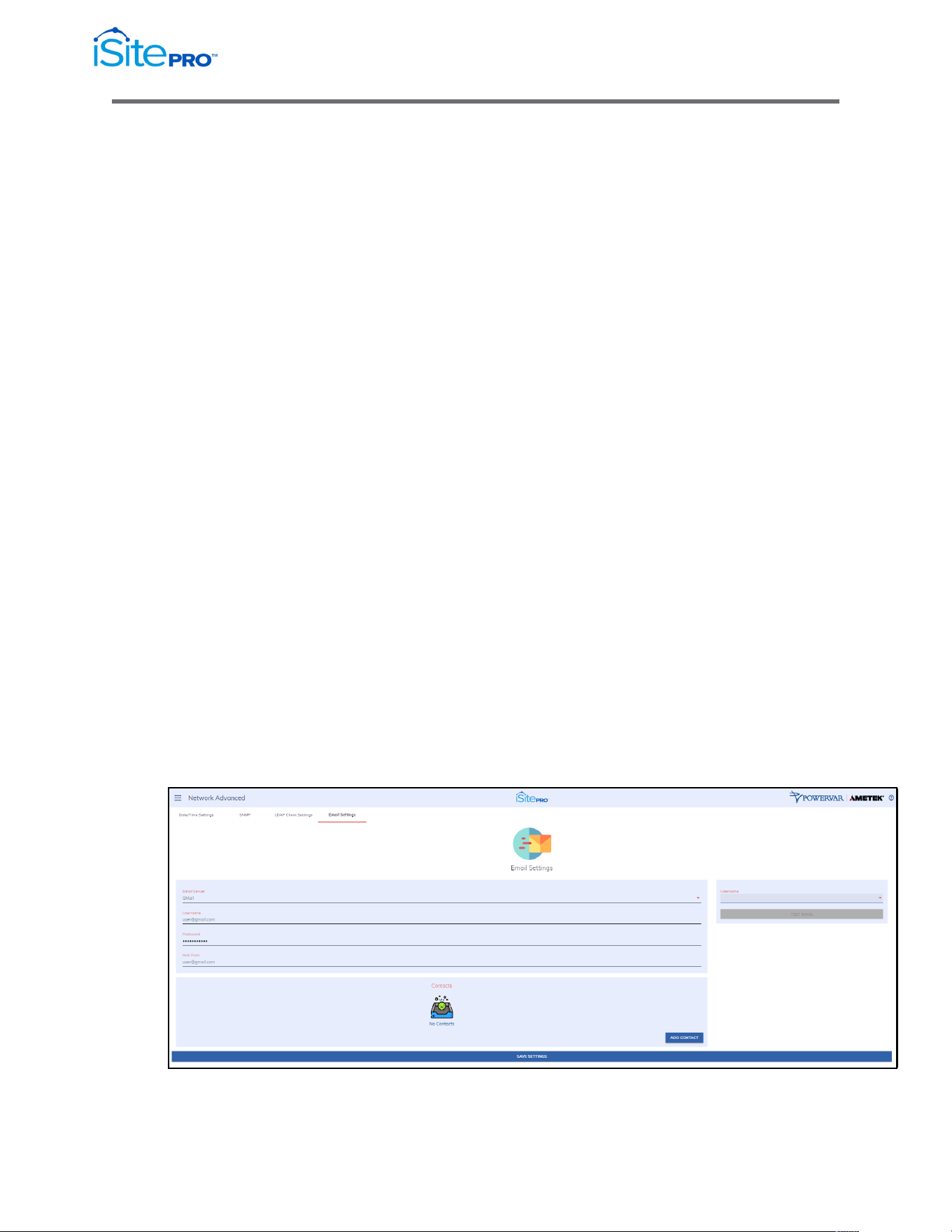
Using Gmail
•
When Gmail is selected as the Email Server, you will only need to
configure the Username, Password and Mail From options as
seen below. It will automatically be configured to use
smtp.gmail.com on port 587 using SSL and Start TLS options.
33
Network Adapter for UPS Management User Manual
© 2021 AMETEK, Inc. / Technical Support: 1-800-645-9721 / surgex.com
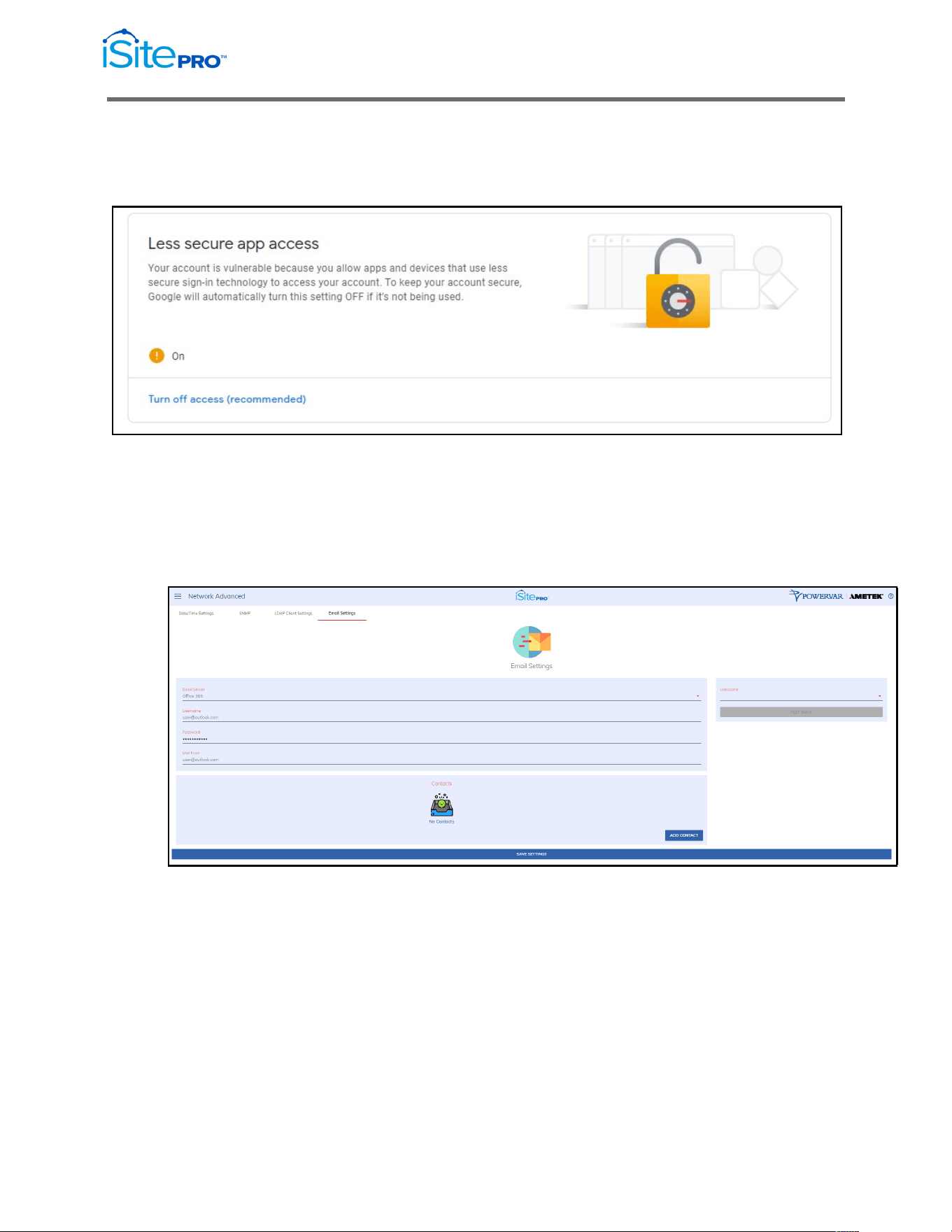
The Secure SMTP option is disabled by default by Google. To enable this
option, you must go to the Security Section of your Google Account and
Allow less secure apps to access your account.
•
Using Office 365
When Office 365 is selected as the Email Server, you will only
need to configure the Username, Password and Mail From options
as seen below. It will automatically be configured to use
smtp.office365.com on port 587 using SSL and Start TLS options.
The Secure SMTP option is disabled by default by Microsoft.
34
Network Adapter for UPS Management User Manual
© 2021 AMETEK, Inc. / Technical Support: 1-800-645-9721 / surgex.com
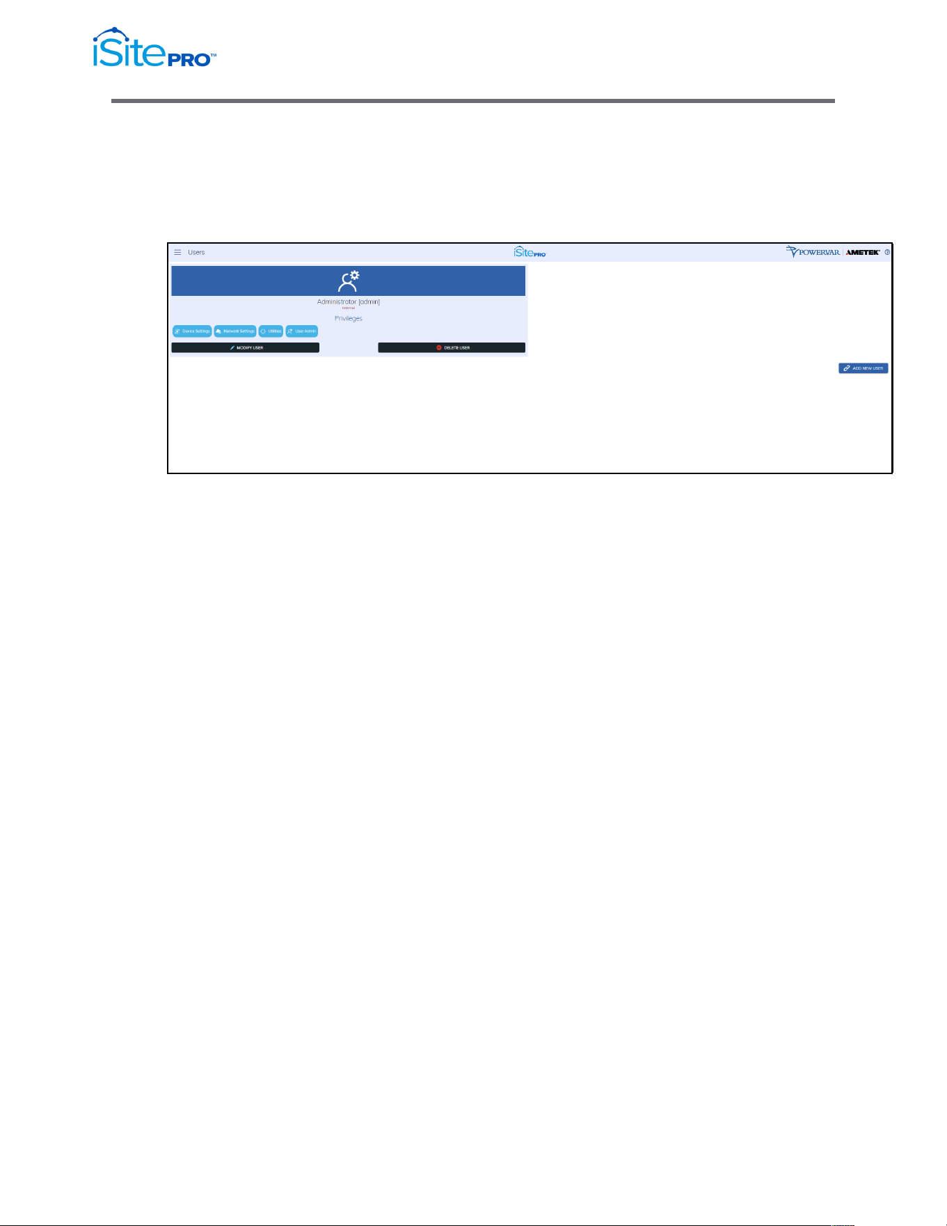
3.9 Users Screen
The Users screen contains the list of currently configured users and their
permissions. Using the Add New User push button New users can be added
using this page.
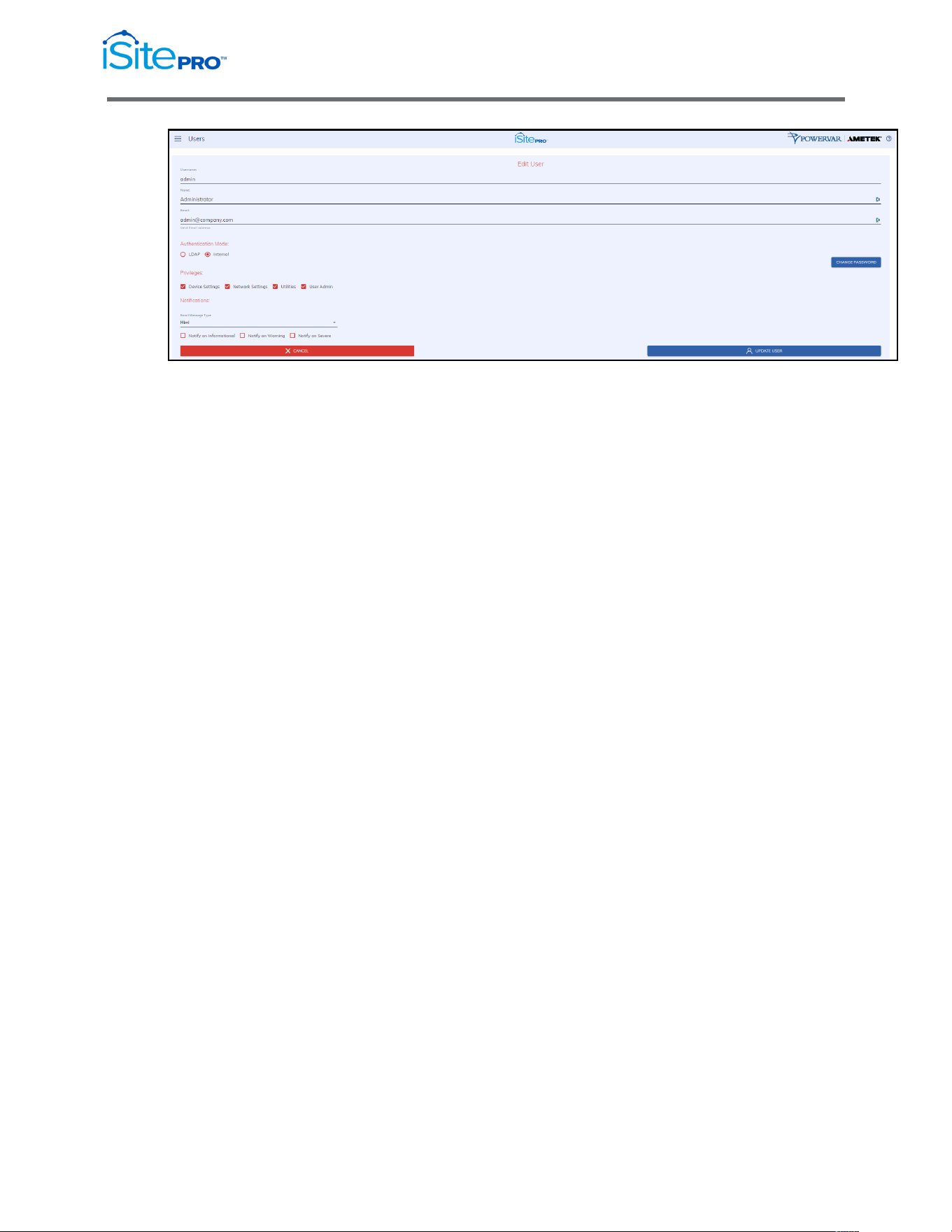
3.9.1 Edit/Add User Account
Use this screen to edit or delete a user. If the user is configured to use an
“Internal” authentication mode, then the iSite PRO performs the
authentication using the passcode, which is stored locally to the iSite
PRO. If the authentication mode is LDAP, then the iSite PRO will use the
LDAP settings configured on the LDAP Client Settings page to
authenticate the user. In this case the passcode of the user is not stored
in the iSite PRO.
The Notifications section allows for configuration of email notifications.
•
Email Message Type: Select the type of Email message to
receive. The options are:
•
Html – The email body will be formatted as HTML
•
Long – The mail body will be formatted as Text and contain
detailed information about the device in the email body.
•
Short – Same as Long but will not contain detailed information
about the device in the email body.
•
Short with no Subject – same as Short but with no subject.
•
Notify on…: Select which type of alarms to be notified on,
Informational, Warning or Severe.
35
Network Adapter for UPS Management User Manual
© 2021 AMETEK, Inc. / Technical Support: 1-800-645-9721 / surgex.com
Privileges
The following access flags are used to control user permissions:
•
UPS Settings: This access flag is required for the user to access
the UPS Settings screen.
•
Network Settings: This access flag is required for the user to
access the Network and Network Advanced screens.
•
Utilities: This access flag is required for the user to access the
Utilities screen.
•
User Admin: This access flag is required for the user to access
the Users screen.
3.10 Utilities
The Utilities allows the user to execute various tasks that backs-up, configures,
restores, reboots, and updates the iSite PRO.
3.10.1 File Upload
Tab
This tab enables the user to upload various updates and configurations of
the iSite PRO:
•
Firmware Update
(Firmware Image File) Use this file to update the firmware of the
iSite PRO.
•
Configuration File
(CFG File) Use this file to update the configuration of the iSite
PRO.
•
SNMP Configuration
(CONF File) Use this file to update the Simple Network
Management Protocol configuration of the iSite PRO.

36
Network Adapter for UPS Management User Manual
© 2021 AMETEK, Inc. / Technical Support: 1-800-645-9721 / surgex.com
•
HTTPS SSL Certificate.
(Security Certificate) Use this file to update the SSL Security
Certificate of the iSite PRO. This file must in pem format.
-----BEGIN CERTIFICATE-----
<content>
-----END CERTIFICATE-----
•
HTTPS SSL Certificate Key
(KEY File) Use this file to update the Certificate Private Key of the
iSite PRO. This file must be in pem format.
-----BEGIN RSA PRIVATE KEY-----
<content>
-----END RSA PRIVATE KEY-----
•
HTTPS SSL Certificate Authorization
(CA File) Use this file to update the Certificate Authorization of the
iSite PRO. This file must be in pem format.
-----BEGIN CERTIFICATE-----
<content>
-----END CERTIFICATE-----
3.10.2 Backup/Restore
Tab
This tab gives an opportunity to backup (snapshot) of the current settings
and users of the iSite PRO. Additionally, the created backup file can be
restored.
3.10.3 Factory Reset Tab
This tab provides a factory reset to restore the iSite PRO to its original
factory settings.
3.10.4 Reboot Device
Tab
This tab provides a reboot to the iSite PRO.
37
Network Adapter for UPS Management User Manual
© 2021 AMETEK, Inc. / Technical Support: 1-800-645-9721 / surgex.com
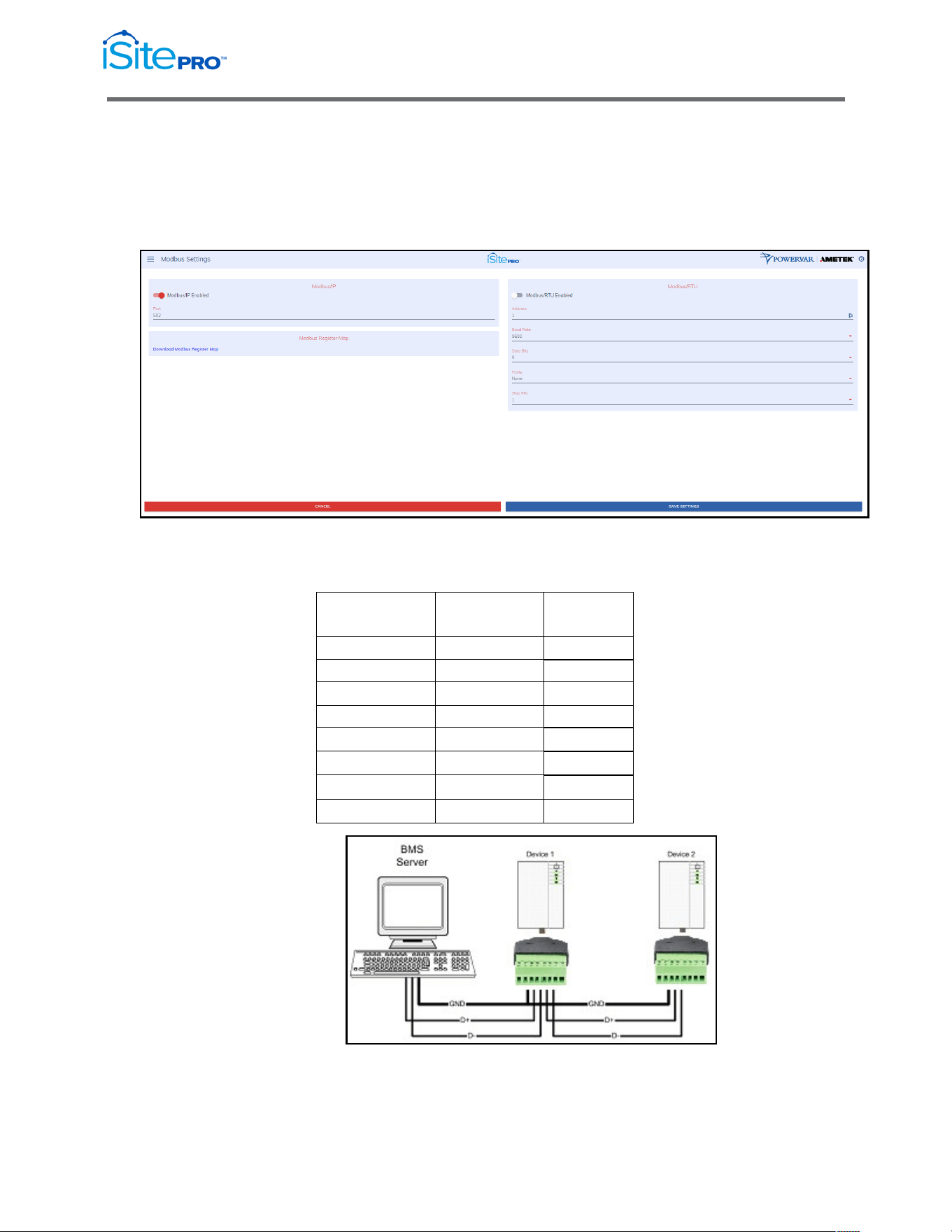
3.11 Modbus Server
The iSite PRO runs a Modbus/IP Server as well as a Modbus/RTU server over
RS485 (half-duplex) on the auxiliary RJ45 port. This feature is only available on
certain models of the iSite PRO.
3.11.1 Modbus/RTU Wiring
The pinout for the BlueBus/Modbus RJ45 connector is as follows:
Pin No.
Blue Bus
RS485
1
HI
-
2
LO
-
3
-
D+
4
VDD
-
5
GND
GND
6
-
D-
7
VDD
-
8
GND
GND
Half Duplex Wiring Diagram

38
Network Adapter for UPS Management User Manual
© 2021 AMETEK, Inc. / Technical Support: 1-800-645-9721 / surgex.com
3.11.2 Modbus/IP Server Settings
•
Modbus/IP Enabled: Enable/Disable the Modbus/IP Server
•
Port: The port the server listens on, this is typically 502.
3.11.3 Modbus/RTU Server Settings
•
Modbus/RTU Enabled: Enable/Disable the Modbus RTU Server
•
Address: The address of this device on Modbus.
•
Baud Rate: The baud rate used by the RS422/485 interface.
•
Parity: The parity used by the RS422/485 interface.
•
Data Bits: The data bits used by the RS422/485 interface.
•
Stop Bits: The stop bits used by the RS422/485 interface.
3.11.4 Modbus Register Map
The MODBUS Register MAP includes identity, measures, and status
information obtained from the UPS by the iSite PRO. This register map is
downloadable from the iSite PRO web interface.
39
Network Adapter for UPS Management User Manual
© 2021 AMETEK, Inc. / Technical Support: 1-800-645-9721 / surgex.com
3.12 Environment Sensors
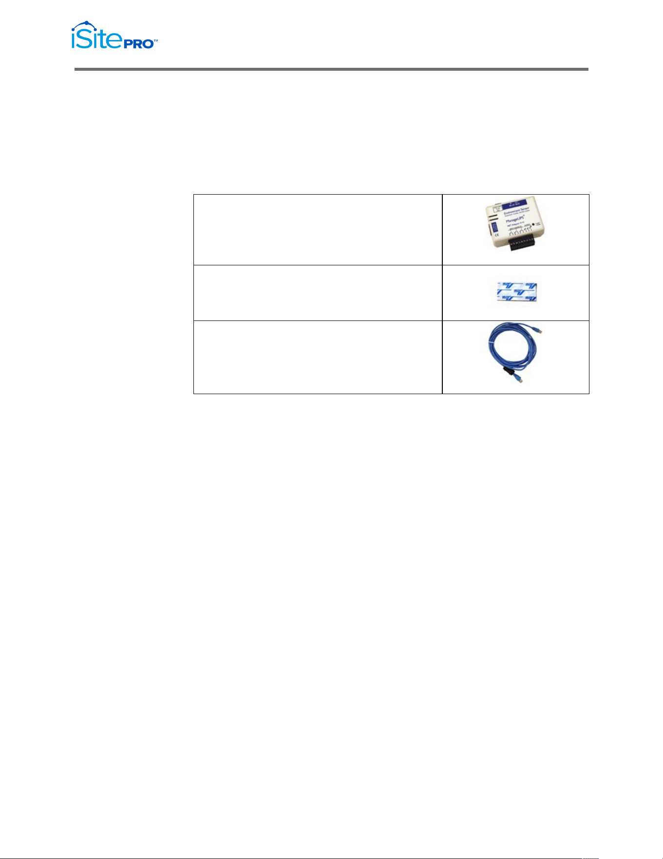
3.12.1 Environment Sensor Kit Components
In addition to the iSite PRO, the following components are provided in the
Environment Sensor Kit.
Environment Sensor
Adhesive Backed Velcro Strip
Blue Bus Cable 3m (~15m)
40
Network Adapter for UPS Management User Manual
© 2021 AMETEK, Inc. / Technical Support: 1-800-645-9721 / surgex.com
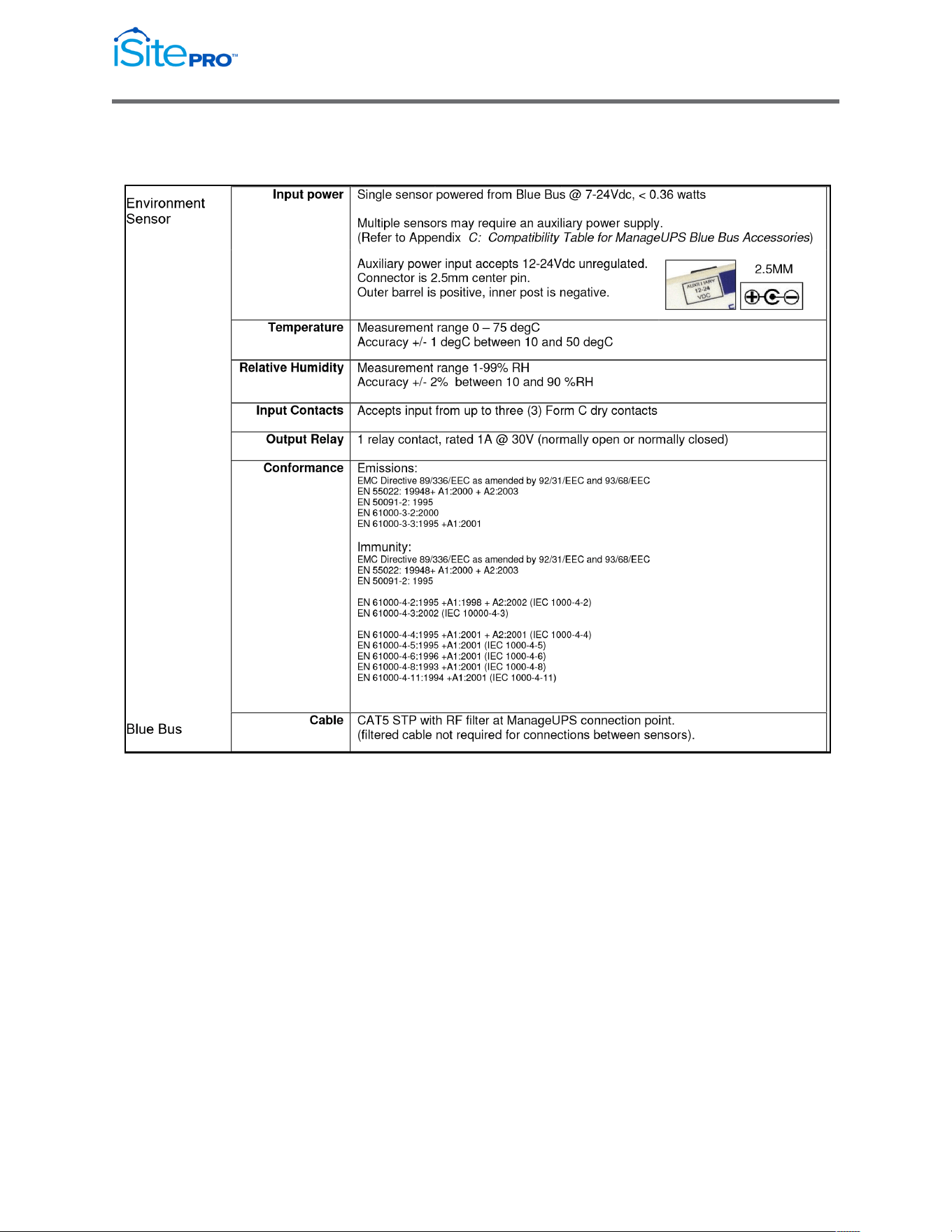
3.12.2 Environment Hardware Specifications
41
Network Adapter for UPS Management User Manual
© 2021 AMETEK, Inc. / Technical Support: 1-800-645-9721 / surgex.com
3.12.3 Hardware Installation
Single Sensor
1. Install the iSite PRO in your UPS
2. Choose a location to mount the sensor within 3m (15’) of you
UPS.
3. Use the adhesive backed Velcro Strip to attach the Sensor to the
mounting location.
4. Connect the Blue Bus cable between the Blue Bus port of the iSite
PRO and a Blue Bus port on the sensor. (Connect the filtered end
of the cable to the iSite PRO).
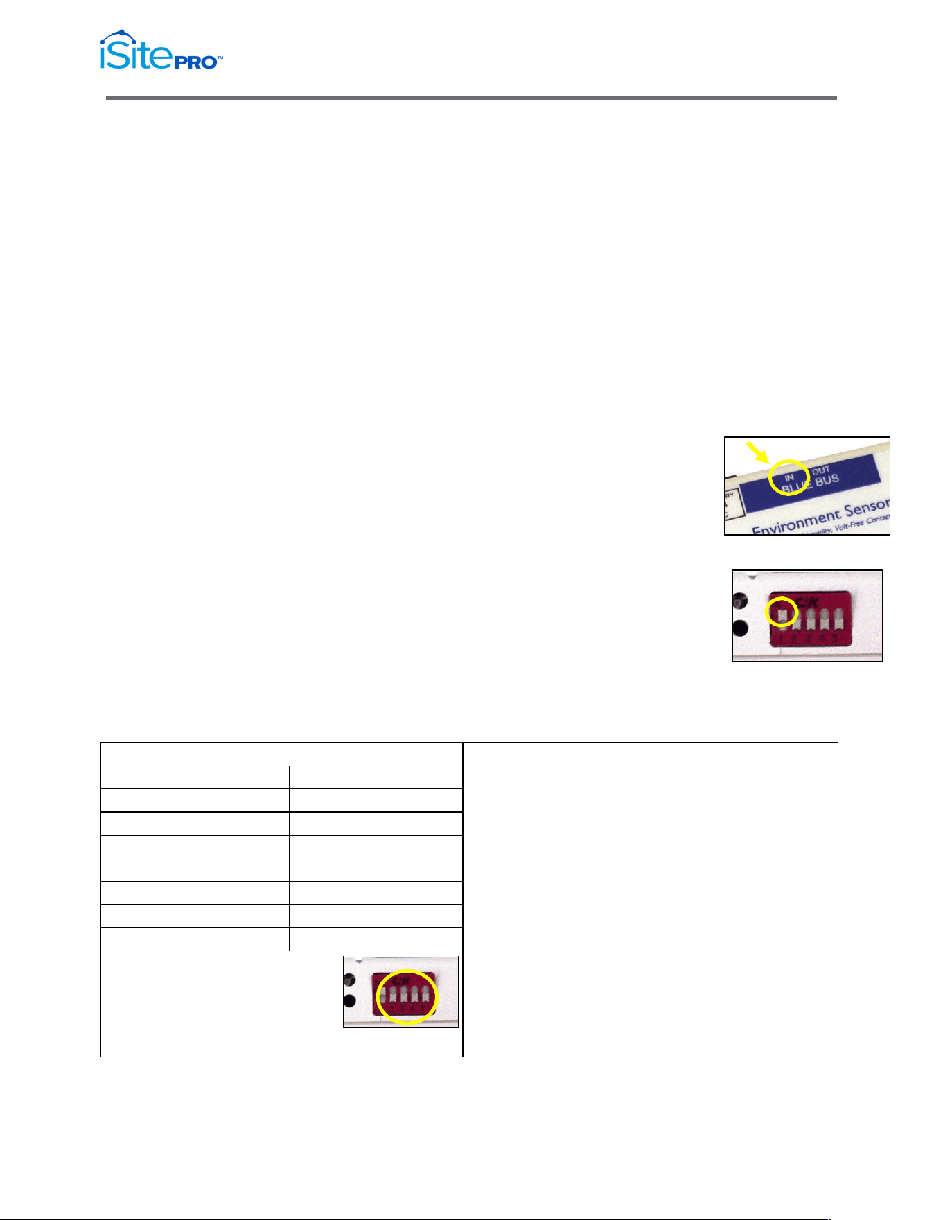
Multiple Sensors
1. Install the first sensor as described above –
making sure to connect the Blue Bus cable from
the iSite PRO to the IN port on the first sensor.
2. Connect a Cat5 STP cable between the Blue Bus
OUT port on the first sensor and IN port on the
second sensor.
3. Set the Terminator (switch #1) on the first sensor
in the DOWN position. Set the terminator in the last
sensor in the UP position.
4. Set the address (switches #2 - #5) of each
additional sensor to be unique – different from the
1
st
sensor and different from any other sensor on the bus.
Address Translation Table
NOTE for Multiple Sensors:
There is a logical limit of 16 addresses available on the
BLUE BUS.
However, the number of sensors that can be added to
the bus without adding supplemental power is limited
by the power available in the UPS communications
accessory slot.
If you need more sensors than your UPS can power, add
supplemental power to any sensor on the bus.
Supplemental power will drive that sensor and any
sensors downstream from the sensor connected to
auxiliary power.
32 = 0000
40 = 1000
33 = 0001
41 = 1001
34 = 0010
42 = 1010
35 = 0011
43 = 1011
36 = 0100
44 = 1100
37 = 0101
45 = 1101
38 = 0110
46 = 1110
39 = 0111
47 = 1111
Address combination (switches #2-5)
in the “all down” position is 0000.
This combination will set the value “32”
as the “address” in the ENVIRONMENT
SENSOR.MIB.
42
Network Adapter for UPS Management User Manual
© 2021 AMETEK, Inc. / Technical Support: 1-800-645-9721 / surgex.com
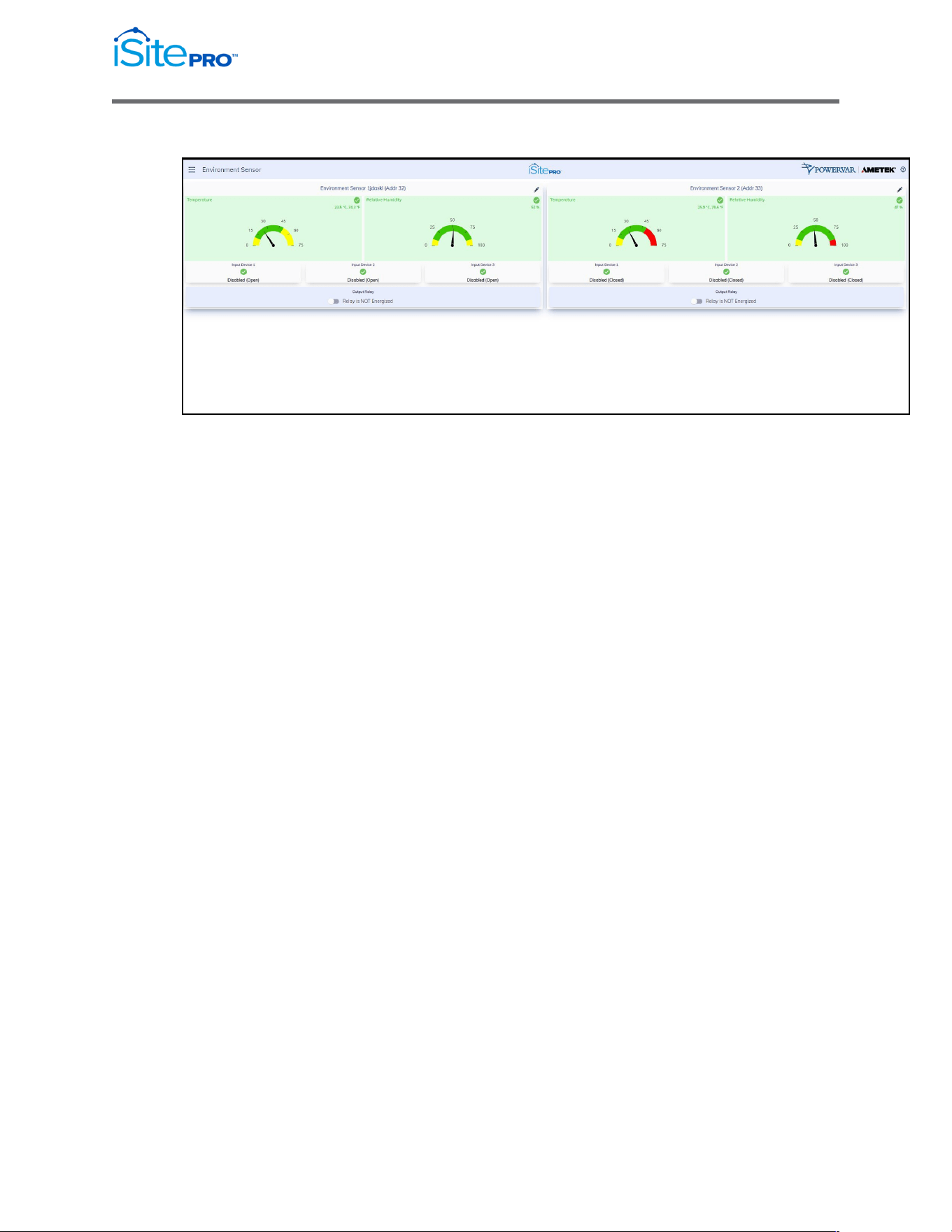
3.12.4 Environment Sensor View
This page will display the status of all Environment Sensors currently
connected to the Blue Bus connector on the iSite PRO.
Environment Measurements
•
Temperature: Current temperature reading in Celsius and
Fahrenheit.
(This value is returned as the temperature object in the
Environment Sensor MIB)
•
Relative Humidity: Current relative humidity reading in percent.
(This value is returned as the humidity object in the Environment
Sensor MIB).
Input Device Status
•
Input Device (1-3) Name: The user configurable name of the
Input Device.
(This value is returned as the inputName1, inputName2,
inputName3 objects in the Environment Sensor MIB)
•
Input Device (1-3) Status: The current status and severity level
of the Input Device. The severity and the normal state of the input
device can be configured on the Environment Sensor
Configuration page.
(This value is returned as the inputStatus1, inputStatus2,
inputStatus3 object in the Environment Sensor MIB)

43
Network Adapter for UPS Management User Manual
© 2021 AMETEK, Inc. / Technical Support: 1-800-645-9721 / surgex.com
Output Relay Status
•
Output Relay Name: The name of the Output Relay.
(This value is returned as the outputName objects in the
Environment Sensor MIB)
•
Output Relay Status: The current state and severity level of the
Output Relay. The conditions which can cause the output relay to
energize can be configured on the Environment Sensor
Configuration page.
(This value is returned as the outputState object in the
Environment Sensor MIB)
44
Network Adapter for UPS Management User Manual
© 2021 AMETEK, Inc. / Technical Support: 1-800-645-9721 / surgex.com
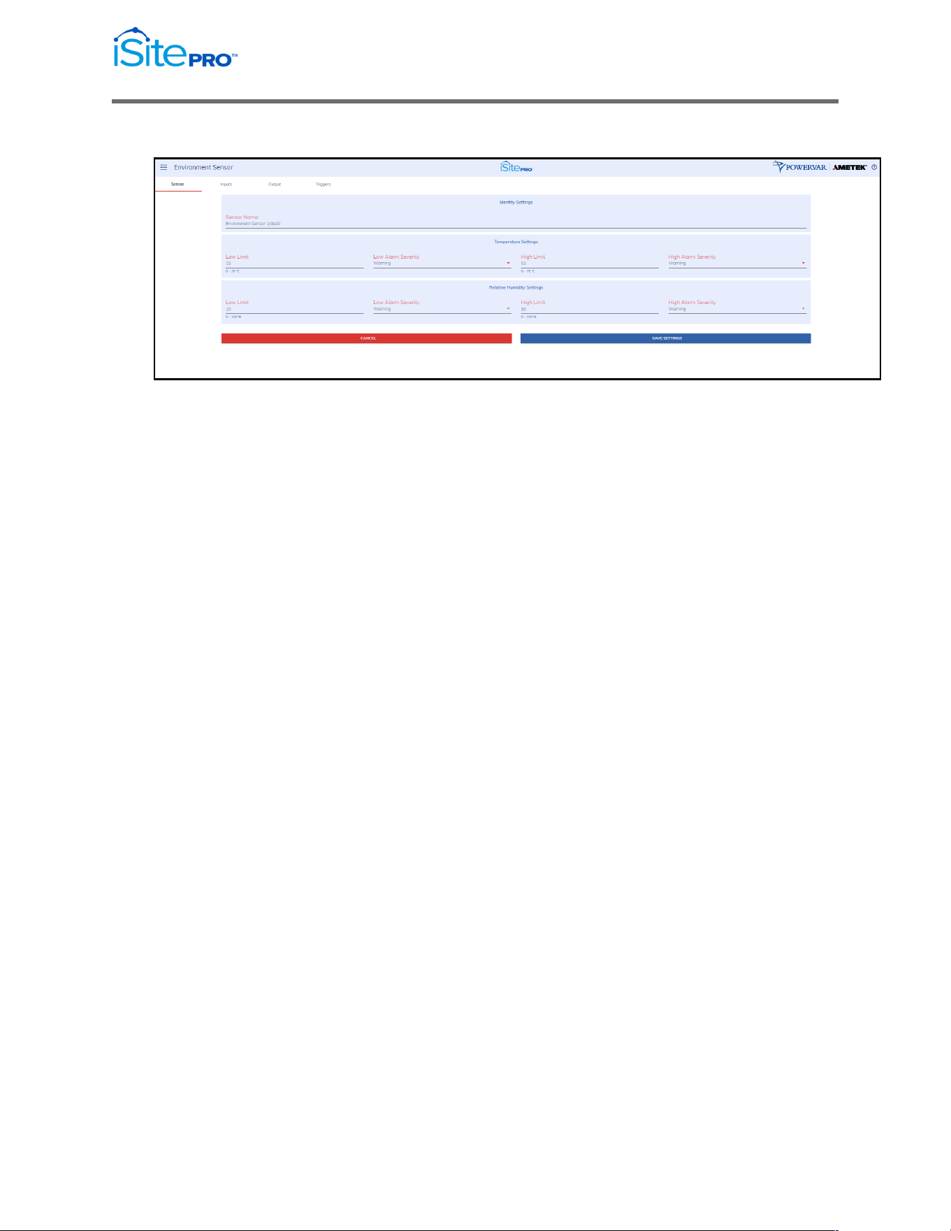
3.12.5 Environment Sensor Configuration
Identity Settings
•
Sensor Name: A name given to the sensor.
(This value is the name object in the Environment Sensor MIB)
Temperature Settings
•
Low Limit: The temperature at which the low temperature
condition is generated for this sensor.
(This value is the tempLoThreshold object in the Environment
Sensor MIB)
•
Low Alarm Severity: The event severity level when temperature
is below the low limit. If disabled, then no event is generated.
•
High Limit: The temperature at which the high temperature
condition is generated for this sensor.
(This value is the tempHiThreshold object in the Environment
Sensor MIB)
•
High Alarm Severity: The event severity level when temperature
is above the high limit. If disabled, then no event is generated.

45
Network Adapter for UPS Management User Manual
© 2021 AMETEK, Inc. / Technical Support: 1-800-645-9721 / surgex.com
Relative Humidity Settings
•
Low Limit: The relative humidity at which the low relative humidity
condition is generated for this sensor.
(This value is the humidityLoThreshold object in the Environment
Sensor MIB)
•
Low Alarm Severity: The event severity level when relative
humidity is below the low limit. If disabled, then no event is
generated.
•
High Limit: The relative humidity at which the high relative
humidity condition is generated for this sensor.
(This value is the humidityHiThreshold object in the Environment
Sensor MIB)
•
High Alarm Severity: The event severity level when relative
humidity is above the high limit. If disabled, then no event is
generated.
46
Network Adapter for UPS Management User Manual
© 2021 AMETEK, Inc. / Technical Support: 1-800-645-9721 / surgex.com
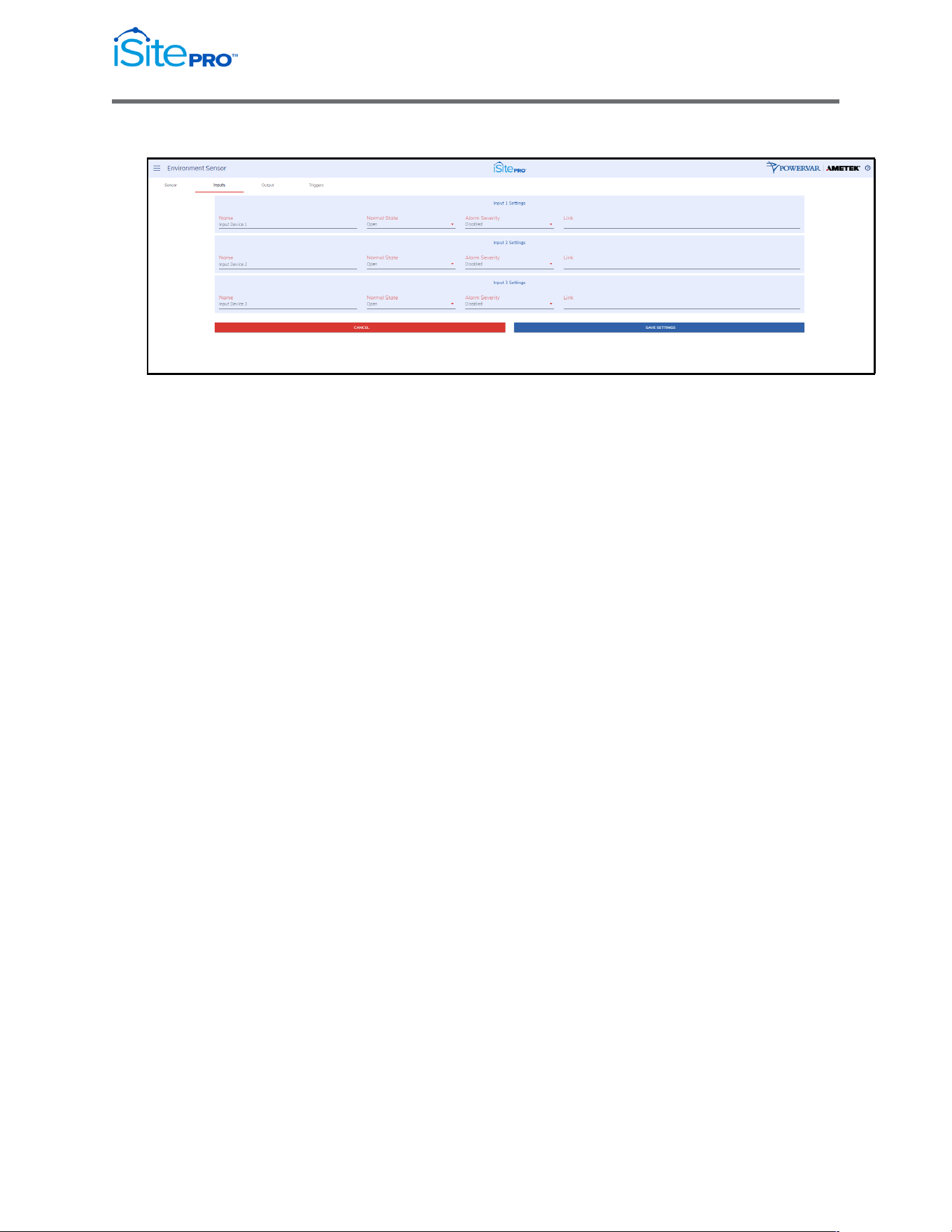
3.12.6 Environment Sensor Inputs
•
Name (1-3): A user configurable name given to the input device.
(These values are the inputName1, inputName2, inputName3
objects in the Environment Sensor MIB)
•
Normal State (1-3): The normal state of the input contact. When
the input contact is not in this state the input fault condition is
generated.
(These values are the inputNormalState1, inputNormalState2,
inputNormalState3 objects in the Environment Sensor MIB)
•
URL (1-3): A url associated with this device. Must be in the format
'http://hostname'. When this value is set the input name becomes
a link on the environment status page.
(These values are the inputUrl1, inputUrl2, inputUrl3 objects in the
Environment Sensor MIB)
•
Alarm Severity (1-3): This setting determines the severity level of
a fault condition on the input. If this setting is Disabled, then no
condition will be generated, and the status will always be Normal.
(These values are the inputFaultSeverity1, inputFaultSeverity2,
inputFaultSeverity3 objects in the Environment Sensor MIB)
47
Network Adapter for UPS Management User Manual
© 2021 AMETEK, Inc. / Technical Support: 1-800-645-9721 / surgex.com
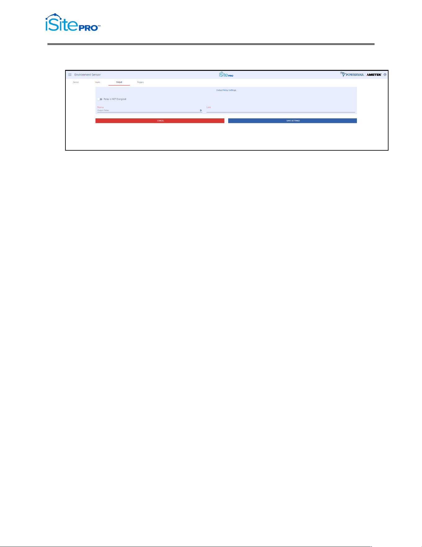
3.12.7 Environment Sensor Output
•
Name: A name given to the output relay. This is usually related to
the device being controlled by the relay.
(These values are the outputName objects in the Environment
Sensor MIB)
•
Link: A url associated with this device. Must be in the format
'http://hostname'. When this value is set the output name becomes
a link on the environment status page.
(These values are the outputUrl objects in the Environment
Sensor MIB)
3.12.8 Environment Sensor Triggers
Triggers are used to configure the relay to energize when any or all of the
selected conditions are present. If no conditions are selected the output
relay is disabled.
3.13 System Info
The System Info screen provides hardware information about the UPS and the
number of users connected to the UPS via the iSite PRO.
3.14 User Profile
The User Profile screen provides the current user’s information. The user can
change their password and modify the email notifications.
3.15 Logout
The Logout option will log out the current user from the iSite PRO UI.
48
Network Adapter for UPS Management User Manual
© 2021 AMETEK, Inc. / Technical Support: 1-800-645-9721 / surgex.com
4.0 Recovery
The iSite PRO can be recovered from an inoperable state by using the USB port.
4.1 USB Setup/Login
a. Using an USB-A to Micro-USB B cable, connect the iSite PRO to a
Laptop/PC
b. Using a web browser go to https://169.254.10.100 to access the USB
Login Screen
c. Enter the credentials for an existing user.
d. Click “LOG IN” pushbutton
e. The user will now have full access to the UI according to their privileges.
4.2 Administrator Credentials
4.2.1 Username and Password
The default username is admin, and the default password is
Adm1nXXXXXX, where XXXXXX are the last six characters of the MAC
address.
49
Network Adapter for UPS Management User Manual
© 2021 AMETEK, Inc. / Technical Support: 1-800-645-9721 / surgex.com
4.2.2 Finding MAC Address of the iSite PRO
Reference the sticker on the iSite PRO.
4.3 Reset Options
Without using credentials, the user can click the “RESET OPTIONS” pushbutton
to restore the iSite PRO to a specific state:
Reset Options Menu:

50
Network Adapter for UPS Management User Manual
© 2021 AMETEK, Inc. / Technical Support: 1-800-645-9721 / surgex.com
4.3.1 Reset Default User
This option resets the admin password to the default password
Adm1nXXXXXX, where XXXXXX are the last six characters of the MAC
address.
4.3.2 Reset Network Settings
This option resets the Network Settings of the iSite PRO to a factory
default state.
4.3.3 Reset To Factory Defaults
This option resets the entire iSite PRO to a factory default state.
4.3.4 Reboot Device
This option reboots the iSite PRO without changing any configurations.
5.0 Application Programming Interfaces
(APIs)
The iSite PRO is designed for flexible communication and integration with diverse
control and monitoring platforms.
5.1 HTTP/HTTPS REST
iSite PRO includes an extensive HTTP API (HTTPS when security is enabled) in
JSON format.
5.2 SNMP
SNMP v1 and v3 communications are intended to provide essential items for
management. Read, Write, Table, and Trap objects will be included.
Support for the following MIB’s is provided:
•
RFC1213 (MIB II)
•
RFC1628 (UPS ManaMOBUSgement Information Base)
•
RFC1157
•
ONEAC Environment Sensor Private MIB

51
Network Adapter for UPS Management User Manual
© 2021 AMETEK, Inc. / Technical Support: 1-800-645-9721 / surgex.com
6.0 Hardware Specifications
6.1 Specifications
Network Interface
10Base-T/100Base-TX IEEE 802.3 compliant
Ethernet transceiver
Auto-negotiation to automatically select the highest
link-up speed (10/100 Mbps) and duplex (half/full)
Main Processor
i.MX RT1050 processors based on Arm Cortex-M7
Core™ Platform
Integrated 10/100 M Ethernet controller with support
for IEEE1588
Integrated FlexCAN module.
Ethernet Controller
Blue Bus
Environmental
Temperature: 0-40 degrees C (32-104 F)
Humidity: 5-90% non-condensing
Altitude: 2,000 m (6,500 ft) maximum
Modbus/RTU
RS422 and RS485 Half Duplex
6.2 Agency Approvals
Safety
EN 60950-1:2006 + A2:2013 Safety of ITE
UL 60950-1, Edition 2
Emissions
EN 55032:2012 + AC:2013; Class A for A.2 (Class A) Radiated Emissions
EN 55032:2012 + AC:2013; Class A for A.3 (Class A) Radiated Emissions
EN 55032:2012 + AC:2013; Class A for A.8 (Class A) Conducted Emissions
Immunity
EN 55024:2010 EMC Immunity Characteristics
EN 61000-4-2 Electrostatic Discharge Immunity
EN 61000-4-3 Radiated Electromagnetic Immunity
EN 61000-4-4 Fast Transients Immunity
EN 61000-4-5 Surge Immunity
EN 61000-4-6 Conducted Immunity
EN 61000-4-8 Magnetic Field Immunity

52
Network Adapter for UPS Management User Manual
© 2021 AMETEK, Inc. / Technical Support: 1-800-645-9721 / surgex.com
Appendix A – UPS Alarm Detail
SNMP
Log Entry &
Alarm SNMP MIB OID Ref: Probable Cause
Condition Email Subject
ID
6
UpsAlarmInputBad
SNMP Trap only
Input power is out of limits or not present.
7
UpsAlarmOutputBad
An output condition is out of tolerance.
SEVERE! Condition Codes
1
UpsAlarmBatteryBad
Module Battery Needs
Replacing
UPS Battery needs replacing.
4
UpsAlarmDepletedBattery
Module Depleted Battery
Run time is just about zero.
5
UpsAlarmTempBad
Module Temperature Limit
was Exceeded
Temperature near the battery is too hot.
8
UpsAlarmOutputOverload
Module Output Overload
Output load power is > 100% of rated capacity.
10
UpsAlarmBypassBad
Module Bypass Bad
The bypass is out of tolerance.
13
UpsAlarmChargerFailed
Module Charger Failed
Battery charger has failed, or its fuse has blown.
16
UpsAlarmFanFailure
Module Fan Failure
Fan failure detected.
17
UpsAlarmFuseFailure
Module Fuse Failure
Input circuit breaker is open, or charger fuse has blown.
18
UpsAlarmGeneralFault
Module Requires Servicing
A UPS fault was detected that is not specifically identified
in the UPS protocol or defined in the standard MIB.
19
UpsAlarmDiagnosticTestFailed
Module Diagnostics Failed
A user-initiated test has failed.
20
UpsAlarmCommunicationsLost
Module Lost
Communications
Adapter has Lost Serial Communications with the UPS.
26*
UpsAlarmBackfeedRelayFailure
Module Backfeed Relay
Failure
Backfeed Relay Failure Detected.
27*
UpsAlarmBatteryFuseBlown
Module Battery Fuse Blown
Battery Fuse failure detected.
29*
UpsAlarmBatteryDegraded
Module Battery Degraded
The UPS detects that the Battery may need to be
replaced soon.
no trap
Module Lost
Communications While
On Battery
Adapter has Lost Serial Communications with the
UPS after the UPS reported an On Battery condition.
System Load Exceeds Power
Margin
The load reported by the UPS exceeds the user specified
power margin.
Probable Cause

53
Network Adapter for UPS Management User
Manual
© 2021 AMETEK, Inc. / Technical Support: 1-800-645-9721 / surgex.com
Warning! Condition Codes
2
UpsAlarmOnBattery
Module On Battery
UPS is running on battery power.
3
UpsAlarmLowBattery
Module Low Battery
Condition
Run time left is less than configured low battery alarm
value.
9
UpsAlarmOnBypass
Module On Bypass
The bypass is engaged by the UPS.
31
UpsAlarmGeneral Warning
Module General Warning
The UPS is indicating an unspecified fault condition.
no trap
Module Running On
Booster
The UPS is correcting a low input line condition without
using battery reserves.
Informational Condition Codes
11
UpsAlarmOutputOff AsRequested
Output Off As Requested
Ups Output Has been Turned off via UPS Com port
command.
12
UpsAlarmUpsOff AsRequested
Module Off As Requested
Ups Has been Turned off via UPS Com port command.
14
UpsAlarmUpsOutputOff
Module Output Is Off
Confirmation that the UPS output is off, but the UPS
control logic is still operating. This trap can only be sent if
the adapter is powered from a source other than UPS
output.
15
UpsAlarmUpsSystemOff
Module System Is Off
UPS output and control logic is off. Will likely never be
seen.
21
UpsAlarmAwaitingPower
Module Awaiting Power
UPS output is off and the UPS is waiting for input power
to be restored.
22
UpsAlarmShutdown Pending
Shutdown Pending On
Module
A UPS shutdown timer has begun counting -- typically
means UPS monitoring software has requested UPS
output to be turned off after a delay period.
23
UpsAlarmShutdown Imminent
Shutdown Imminent On
Module
Output shutdown will occur in approximately 5 seconds.
24
UpsAlarmTestIn Progress
Module Diagnostics Test in
Progress
A user requested UPS test has begun.
25
UpsAlarmBattery Charging
Module Battery Charging
The UPS Battery is recovering from a recent discharge.
28
UpsAlarmSystemRestart Pending
System Restart Pending
The UPS is counting a user specified restart delay after AC
input returns.
30
UpsAlarmAutonomy
Calibration
Module Autonomy
Calibration
The UPS is discharging the battery and calibrating its run
time (autonomy) estimates.