USER MANUAL
ELITE
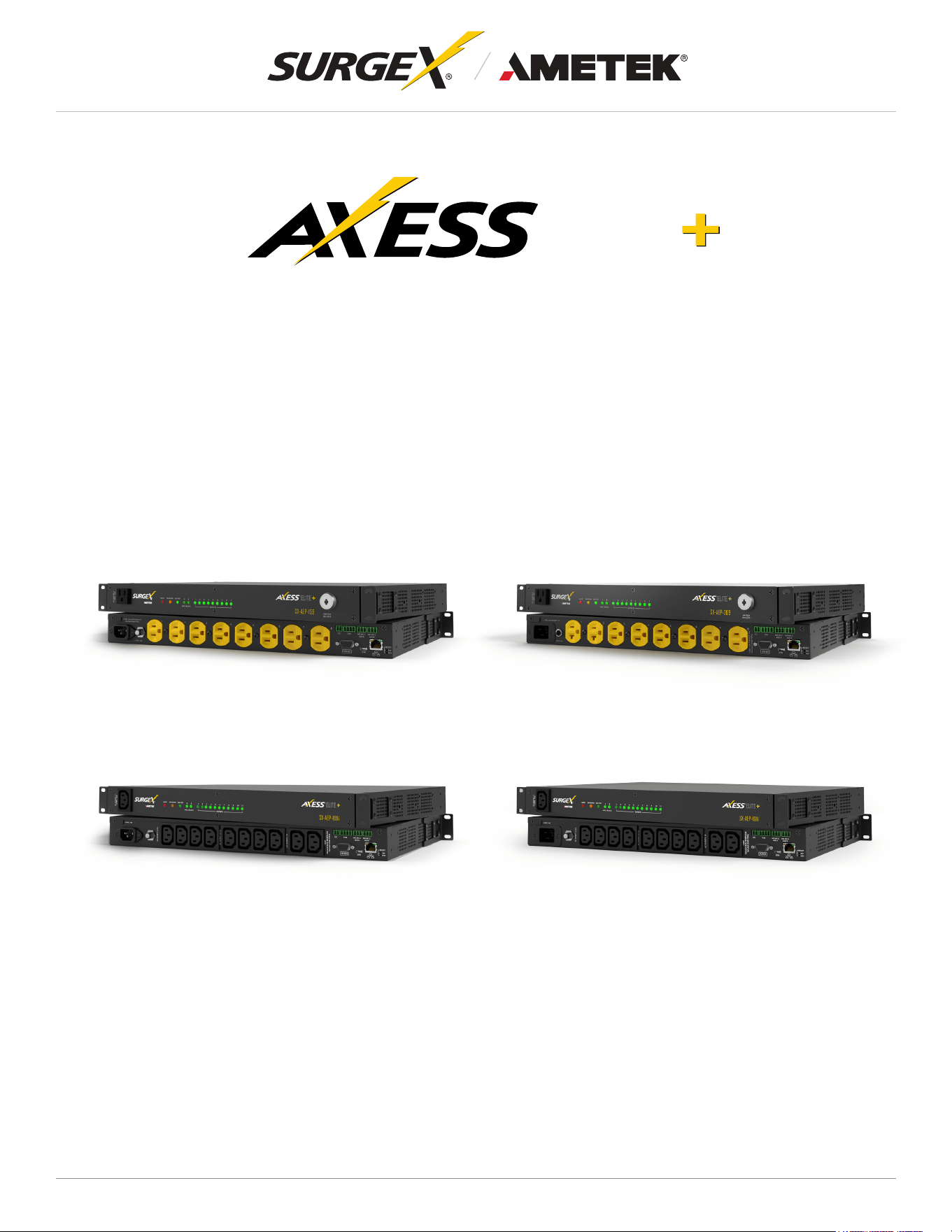
SX-AEP-1011i
SX-AEP-159 SX-AEP-209
SX-AEP-1611i
Switched IP-Controllable Surge Protected PDU
©2025 AMETEK SurgeX | B01-00014 (REV A) Technical Support: 800-645-9721 | surgex.com

ELITE
User Manual
©2025 AMETEK SurgeX | B01-00014 (REV A) Technical Support: 800-645-9721 | surgex.com

ELITE
User Manual
©2025 AMETEK SurgeX | B01-00014 (REV A) Technical Support: 800-645-9721 | surgex.com
Table of Contents
1. Introduction ...................................................................................................................... 1
1.1 Metering is performed at the system level, and includes: ................................................................1
1.2 Physical Interfaces ...........................................................................................................................2
1.3 Rating...............................................................................................................................................2
2. Installation and Components ......................................................................................... 3
2.1 AC Power: Output ...........................................................................................................................3
2.2 AC Power: Input ..............................................................................................................................3
2.3 Ethernet and Account Admin Password ...........................................................................................3
2.4 USB-Micro AB ..................................................................................................................................4
2.5 Connect Serial Port (Optional) .........................................................................................................4
2.6 Connect Contact Closure Input (Optional) .......................................................................................4
2.7 Connect Temperature / Humidity Sensor (Optional) ........................................................................4
2.8 Connect Auxiliary Relay Outputs (Optional):....................................................................................4
2.9 Wiring details: ..................................................................................................................................5
2.10 LED Indicators: ................................................................................................................................5
2.11 Buttons ............................................................................................................................................5
2.11.1 Resettable Fuse ................................................................................................................5
2.11.2 Hardware Reset ................................................................................................................5
2.11.3 Software Reset ..................................................................................................................5
2.11.4 Front Key Switch ...............................................................................................................6
3. Rack Installation .............................................................................................................. 6
3.1 Rack Mounting Options....................................................................................................................7
3.2 Unit Installation into the Rack ..........................................................................................................7
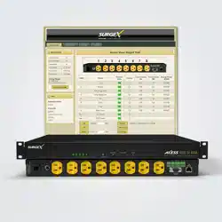
4. Web Server ....................................................................................................................... 8
4.1 Login ................................................................................................................................................8
4.2 Power Management .........................................................................................................................8
4.3 Reports ............................................................................................................................................9
4.4 Power Monitoring ...........................................................................................................................10
4.5 Chart ..............................................................................................................................................10
4.6 Setup..............................................................................................................................................11

ELITE
User Manual
©2025 AMETEK SurgeX | B01-00014 (REV A) Technical Support: 800-645-9721 | surgex.com
4.6.1 Device Setup ...................................................................................................................12
4.6.1.1 DeviceConguration .....................................................................................12
4.6.1.2 OutletConguration .......................................................................................13
4.6.1.3 OutletGroupConguration ............................................................................14
4.6.1.4 Date/Time Settings ........................................................................................14
4.6.2 Network Setup .................................................................................................................15
4.6.3 Network Advanced Setup ................................................................................................16
4.6.3.1 SNMP.............................................................................................................16
4.6.3.2 802.1X Settings .............................................................................................17
4.6.3.3 LDAP Client Settings .....................................................................................18
4.6.3.4 Syslog Settings .............................................................................................19
4.6.4 Cloud Setting ...................................................................................................................20
4.6.5 Users ...............................................................................................................................20
4.6.6 Triggers Setup .................................................................................................................21
4.6.6.1 Threshold with Samples ................................................................................23
4.6.6.2 Autoping .........................................................................................................23
4.6.6.3 Schedule ........................................................................................................23
4.6.6.4 Contact Closure .............................................................................................24
4.6.7 Sequences Setup ............................................................................................................24
4.7 Utilities ...........................................................................................................................................24
4.7.2 Backup/Restore ...............................................................................................................25
4.7.3 Factory Reset ..................................................................................................................25
4.7.4 Soft Reboot .....................................................................................................................25
4.8 UserProle ....................................................................................................................................26
4.9 System info ....................................................................................................................................26
5. Command Line Interface (CLI) ...................................................................................... 27
5.1 SSH................................................................................................................................................27
5.2 RS 232 PORT ................................................................................................................................27
5.3 Commands.....................................................................................................................................28

ELITE
User Manual
©2025 AMETEK SurgeX | B01-00014 (REV A) Technical Support: 800-645-9721 | surgex.com
6. Security ........................................................................................................................... 31
6.1 Authentication ................................................................................................................................31
6.1.1 802.1X .............................................................................................................................31
6.1.2 SSO (Single Sign-On) .....................................................................................................31
6.2 Interfaces .......................................................................................................................................32
6.2.1 Network Interface ...........................................................................................................32
7. Application Programming Interfaces (APIs) ............................................................... 32
7.1 HTTP/HTTPS REST ......................................................................................................................32
7.2 Interfaces .......................................................................................................................................32
8. Part Numbers ................................................................................................................. 32
8.1 Part Number Scheme ....................................................................................................................32
9. Troubleshooting ............................................................................................................. 33
10. Specications ................................................................................................................ 34

1
ELITE
User Manual
©2025 AMETEK SurgeX | B01-00014 (REV A) Technical Support: 800-645-9721 | surgex.com
1. Introduction
The SurgeX Axess ELITE+ is an AC power distribution unit with power conditioning, control, and monitoring
with independently IP switchable AC receptacles and current monitoring for individual outlet. Designed for
mounting on the rack with supplied mounting brackets or sitting on a counter with supplied rubber feet. The
internalwebserverprovidesconguration,outputcontrol,monitoring,Individualoutputcurrentmonitoring
and retrieval of data logs. Multiple security and communication interface options are supported.
Axess ELITE+ incorporates SurgeX’s patented technology, Advanced Series Mode
®
surge suppression
andEMI/RFIlteringtechnology.ThisprotectionsafeguardstheACoutlets.ItalsoprovidesInrushCurrent
Elimination circuitry (on receptacles 1 and 2).
Two Auxiliary Relay outputs are provided for simple control of other equipment. Connection terminals are
provided for each relay’s Common, Normally Open, and Normally Closed connections.
The extensive programming capabilities of the Axess ELITE+ provides advanced sequencing and scheduling
operations. Triggers can be programmed to activate on an “if X then do Y, then do Z when no longer X”
basis. Trigger sources include various AC power measurements, scheduling, and AutoPing. Actions include
turningreceptaclesonandoff,cyclingareceptacle,executingpreviouslydenedsequences,andputting
a unit into shutdown. For example, an action can be created to power cycle a network appliance if it fails to
respond to a series of pings.
1.1 Metering is performed at the system level, and includes:
• Line Voltage
• Neutral-Ground Voltage
• Each Outlet Current
• Each Outlet Power
• Line Frequency
• Each outlet Power Factor
• Crest Factor
• Each Outlet Energy

2
ELITE
User Manual
©2025 AMETEK SurgeX | B01-00014 (REV A) Technical Support: 800-645-9721 | surgex.com
1.2 Physical Interfaces
MODEL OUTPUT INPUT COMMUNICATION RESETTABLE FUSE
SX-AEP-159 (9) NEMA 5-15R (1) NEMA 5-15P
(1) RJ-45
(1) USB-Micro AB
(1) Serial Port
(1) Contact Closure
(1) Push Button
SX- AEP -209
(7) NEMA 5-15R,
(2) NEMA 5-20R
(1) NEMA 5-20P
(1) RJ-45
(1) USB-Micro AB
(1) Serial Port
(1) Contact Closure
(1) Push Button
SX- AEP -1011i (11) IEC 13 (1) IEC C14
(1) RJ-45
(1) USB-Micro AB
(1) Serial Port
(1) Contact Closure
(1) Push Button
SX- AEP -1611i (11) IEC 13 (1) IEC C20
(1) RJ-45
(1) USB-Micro AB
(1) Serial Port
(1) Contact Closure
(1) Push Button
1.3 Rating
MODEL OUTLET DETAILS
RATED INPUT
VOLTAGE
RATED INPUT
CURRENT
FREQUENCY
SX-AEP-159 9 Outlets / 5-15R 120V AC 12 A 50/60 Hz
SX-AEP-209
2 Outlets / 5-20R
7 Outlets / 5-15R
120V AC 16 A 50/60 Hz
SX-AEP-1011i 11 Outlets / IEC C13 240V AC 10 A 50/60 Hz
SX-AEP-1611i 11 Outlets / IEC C13 240V AC 16 A 50/60 Hz
3
ELITE
User Manual
©2025 AMETEK SurgeX | B01-00014 (REV A) Technical Support: 800-645-9721 | surgex.com
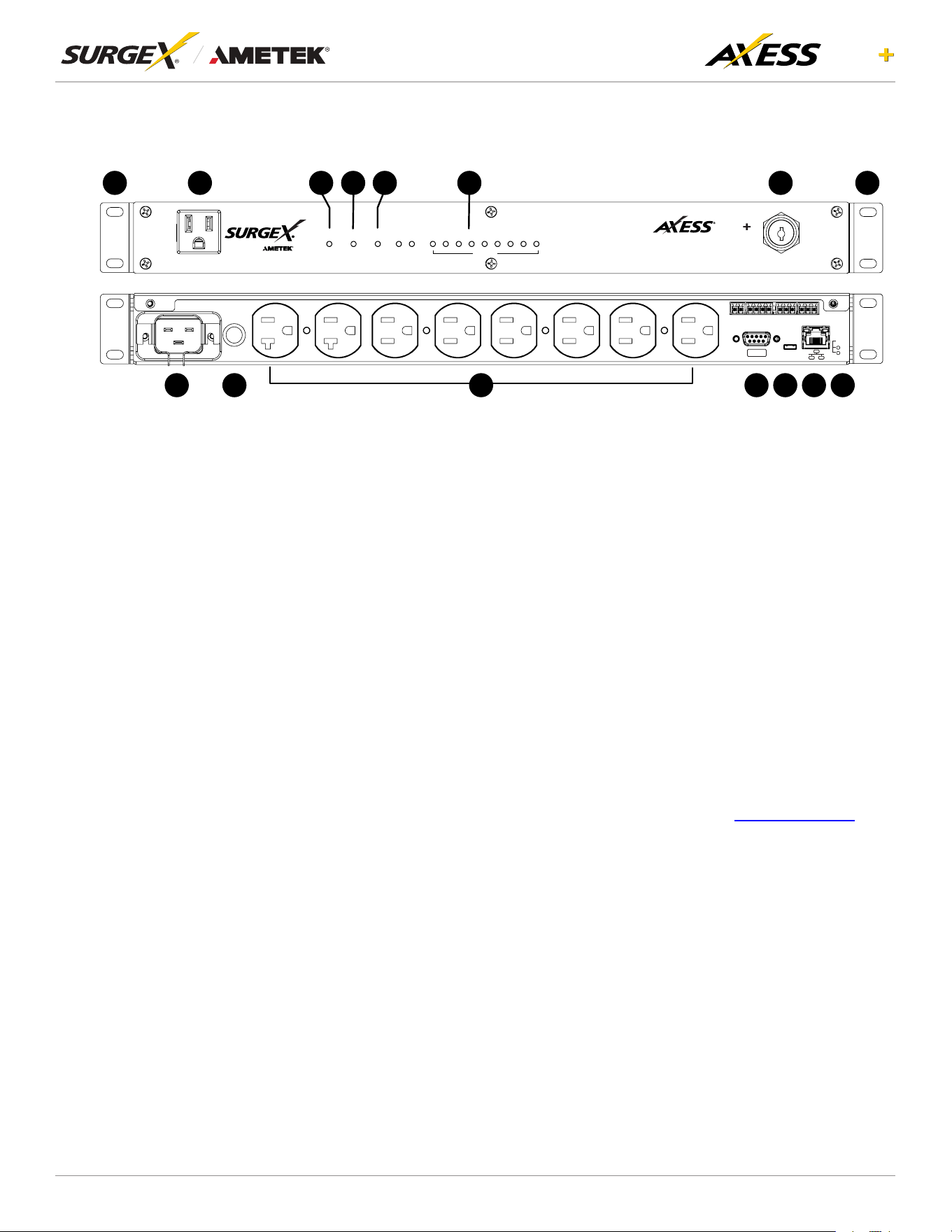
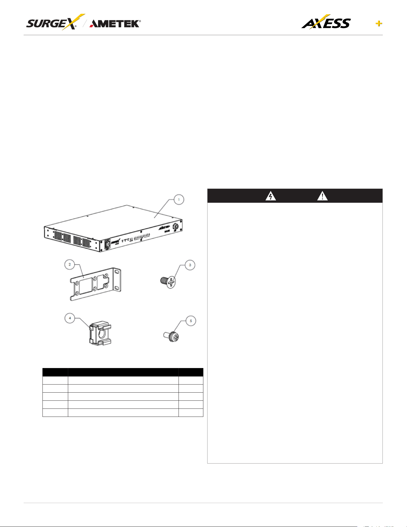
2. Installation and Components
1 2 3 4 5 6 7 8 9
SELF -TEST
A B
SHUTDOW N
OUTLETSAUX, RELAYS
MAINS
SX-AEP-209
AC OUTLET 9
~120V, 12A
ELITE
1 2 3 4 5 6 7 8
~120V, 16A FOR RCPT 1-2
~120V, 16A
CC T/H
NO NC C
AUX A
NO NC C
AUX B
IO I OI
US B
RE SE T
SW
HW
~120V, 12A FOR RCPT 3-8
16A MAX LOAD TOTAL
B
D I/JV H K E
B
FCLG
MA A
AxessELITE+isdesignedtobeinstalledhorizontallyontheequipmentrackorplacedonaatsurface.The
supplied nuts, bolts and washers must be used to mount the Axess ELITE+ to the rack through the mounting
holes (A) following the appropriate local regulations and requirements. If the Axess ELITE+ is used outside
of a rack, attach the supplied rubber feet.
2.1 AC Power: Output
Plug the equipment cord (B) into the suitable receptacles as needed. Please review Introduction,
Physical Interfaces, column Outputs, for the suitable plugs for each model’s receptacles.
2.2 AC Power: Input
Connect power to the Axess ELITE+ using an appropriately rated 3 wire grounding type power cord
provided with the equipment in inlet (V). Do not plug the unit into a relocatable power tap. Check the
outlet for correct polarity and presence of a ground conductor before plugging the unit in.
2.3 Ethernet and Account Admin Password
The RJ-45 connector for Ethernet (D) is situated on the back panel. The default IP Address is DHCP
assigned.To ndIPaddress ofthedevice, pleaseuse the discoverytool atametekesp.com. The
mDNS protocol is supported for dynamic device discovery.
The default login credentials are:
Username: admin
Default password: Adm1nXXXXXX
Where XXXXXX are the last six characters of the MAC address.

4
ELITE
User Manual
©2025 AMETEK SurgeX | B01-00014 (REV A) Technical Support: 800-645-9721 | surgex.com
2.4 USB-Micro AB
The USB-Micro AB connector (E) is for diagnostics and troubleshooting IP connectivity issues.
To use, please use the discovery tool at ametekesp.com or manually enter the static IP address
http://169.254.10.100 into a supported browser. The web server will always be accessible at
http://169.254.10.100 through this USB port. The web server on this interface cannot be changed and
will always be unsecured HTTP at port 80.
2.5 Connect Serial Port (Optional)
The Axess ELITE+ has a 9 pin D subminiature connector (K) for RS- 232 serial control. The connector is
conguredasDCEfordirectconnectiontoalaptoporotherterminaldevice.Defaultserialparameters
are 115200 bps, 8 data, no parity, 1 stop bit (115200,8, n,1).
2.6 Connect Contact Closure Input (Optional)
Connectcontactclosurecontrolinputtothe2pinsoftherstterminalblockasshowninsection2.9.
Relays, switches, and push buttons are all suitable input types. The wire size can range from 18 AWG
to 22 AWG.
2.7 Connect Temperature / Humidity Sensor (Optional)
The Axess ELITE+ comes with external Temperature and Humidity sensor (Part No. SEN0385) for
monitoring external environmental conditions. This sensor can be connected via the green Phoenix
Connectors on the device. Connect red wire to pin 1, SDA (Green/Blue) to pin 2, SCL (Yellow/White)
to pin 3 and black wire to pin 4 of the second terminal block as shown in the below wire connection
section 2.9. Real-time external temperature and humidity values are displayed in the system info
(section 4.9). The temperature data can be utilized to set triggers and actions (section 4.6.6). However,
humidity values cannot be used as input for triggers. Additionally, these values are not stored or
displayed as historical data; only real-time values are made visible in the system info page.
2.8 Connect Auxiliary Relay Outputs (Optional):
Two auxiliary relay outputs are provided at the third (Aux Relay A) and fourth (Aux Relay B) terminal
blocks as shown in section 2.9. Access to the Common, Normally Open, and Normally Closed positions
is provided for each relay. The wire size can range from 18 AWG to 22 AWG.
5
ELITE
User Manual
©2025 AMETEK SurgeX | B01-00014 (REV A) Technical Support: 800-645-9721 | surgex.com
2.9 Wiring details:
Contact Closure
CC1 CC2 +5V SDA SCK GND NO NC COM NO NC COM
Temperature/Humidity Auxiliary Relay A Auxiliary Relay B
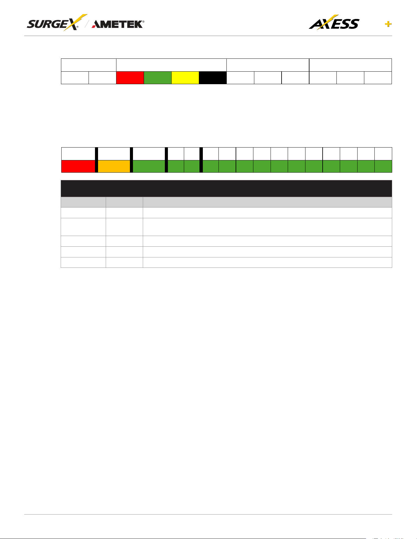
2.10 LED Indicators:
The receptacles have individual power indicator LEDs (F). This are paralleled in the control interface.
In addition, the unit has an LED indicating power (G), Shut down is indicated by (L) and Self -Test is
indicated by (C).
Mains Shutdown Self-Test
A B 1 2 3 4 5 6 7 8 9 10 11
LED INDICATORS
Indicator Colour Description
Mains Red Whenilluminated,theAxessEliteisconnectedtoalivewallorooroutlet.
Shutdown Amber
When illuminated, the Axess Elite is in shutdown mode due to out of range line voltage,
current, or temperature.
Self-Test Green When illuminated, the surge suppression circuitry is functioning correctly.
Aux Relays Green When illuminated, the corresponding auxiliary relay is latched.
Outlets Green When illuminated, the corresponding AC outlet is on.
2.11 Buttons
2.11.1 Resettable Fuse
The resettable fuse (H) is used to reset the Axess ELITE+ in case the fuse tripped. This is a
single push button to the bottom left of the Ethernet RJ-45 jack. Also, there is a reset switch
for hardware and another for software.
2.11.2 Hardware Reset
Hardware Reset (I): The Hardware Reset button performs a hard reboot of the processor.
This hard reboot will immediately switch controlled outlets off, removing power to connected
equipment on all outputs.
2.11.3 Software Reset
Software Reset (J): The Software Reset button is a multi-functional control depending on
length of press. If the button is held for longer than 10 seconds, the unit resets itself to factory
defaults, and all custom congurations are erased. If the button is held for less than 10
seconds, the unit will perform a software reset that will not reset any data, or power cycle the
connected equipment.
6
ELITE
User Manual
©2025 AMETEK SurgeX | B01-00014 (REV A) Technical Support: 800-645-9721 | surgex.com
2.11.4 Front Key Switch
Front key Switch (M): The front key switch is used to turn the unit on and off. Use the provided
key, which comes in the box, to turn the switch to the right (clockwise) to switch the unit on,
and to the left (anticlockwise) to switch it off. The key can be removed from the unit in both
the on and off positions. Make sure to store the key safely in a secure place when not in use
to prevent loss or damage. The front key switch shall be only for the SX-AEP-159 and SX-
AEP-209 models.
3. Rack Installation
Axess ELITE+ is designed to be installed horizontally in the equipment rack. The supplied nuts, bolts and
washers must be used to mount the Axess ELITE+ to the rack through the mounting holes (A) following the
appropriate local regulations and requirements.
Inventory
SI. No Items Qty
1 Axess ELITE+ Unit 1
2 Ear Mount Bracket 2
3 Flat Head Screws 8
4 Cage Nut 4
5 Pan Head Screws 4
DANGER
HAZARD OF ELECTICAL SHOCK, EXPLOSION, OR ARC FLASH
• This Unit is intended to use indoor only.
• Do not install this Unit where excessive moisture or heat is present.
• Never install any wiring, equipment, or Units during a lightning storm.
• Plug this Unit into a three-wire, grounded power outlet only. The power
outlet must be connected to appropriate branch circuit/mains protection
(fuse or circuit breaker). Connection to other type of power outlet may result
in a shock hazard.
• Install the unit in such a way that the Wall socket-outlet should be readily
accessible.
• Use only the supplied brackets for mounting and use only the supplied
hardware to attach the mounting brackets
• Do not use extension cords or adapters with this Unit
• If a socket-outlet is not accessible to the equipment, a socket-outlet shall be
installed.
• Do not work alone under hazardous conditions.
• Check that the power cord, plug, and socket are in good condition.
• Disconnect the Unit from the power outlet before you install or connect
equipment to reduce the risk of electric shock when you cannot verify
grounding. Reconnect the Surge Unit to the power outlet only after you
make all connections
• UnitinstallationinstructionsthatrequirevericationoftheProtective
earthing connection of the socket-outlet by a Skilled person.
• This equipment is not suitable for use in locations where children are likely
to be present.
• Use a protective earth connector with equipment. This type of connector
carries the leakage current from the load devices (computer equipment).
• Do not exceed a total leakage current of 3.5 mA
• Do not handle any kind of metallic connector before the power has been
removed
• Use one hand, whenever possible, to connect or disconnect signal cables to
avoid a possible shock from touching two surfaces with different grounds.
• This unit does not have any user-serviceable parts. Repairs are to be
performed only by factory-trained service personnel.
• The Unit is intended to be installed and operated by a skilled person in as
controlled location with restricted access.
• The ambient operating temperature of a closed or multi-unit rack
environment may be greater than the ambient temperature of the room.
Ensure the ambient operating temperature of your rack environment does
not exceed the rated ambient operating temperature for the device.
• Ensure the Unit is mounted securely and evenly.
• To avoid possible electrical shock and equipment damage, Use only the
supplied hardware.
Failure to follow these instructions will result in death or serious injury
7
ELITE
User Manual
©2025 AMETEK SurgeX | B01-00014 (REV A) Technical Support: 800-645-9721 | surgex.com
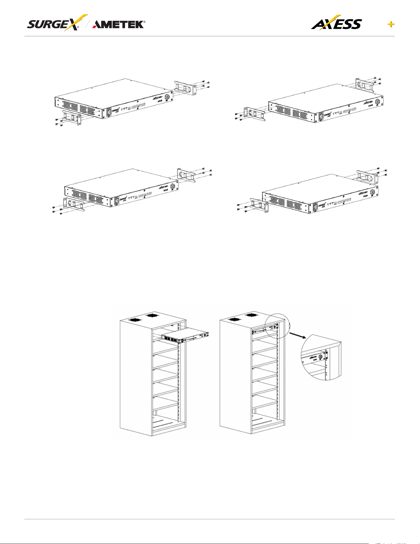
3.1 Rack Mounting Options
Option 1: Mounting Ear Mount Bracket at Front
Secure Ear Mount Brackets to the Unit using eight Flat head screws
Option 2: Mounting Ear Mount Bracket at Rear
Secure Ear Mount Brackets to the Unit using eight Flat head screws
Option 3: Mounting Ear Mount Bracket at the Center
Secure Ear Mount Brackets to the Unit using eight Flat head screws
Option 4: Mounting Ear Mount Bracket at the Center
Secure Ear Mount Brackets to the Unit using eight Flat head screws
3.2 Unit Installation into the Rack
Horizontal Mounting: Mount Unit on 19” rack holes provided in the channel and secure the Unit using
four Pan head screws.
8
ELITE
User Manual
©2025 AMETEK SurgeX | B01-00014 (REV A) Technical Support: 800-645-9721 | surgex.com
4. Web Server
Axess ELITE+’s internal web server provides a comprehensive portal for conguration, monitoring and
control.
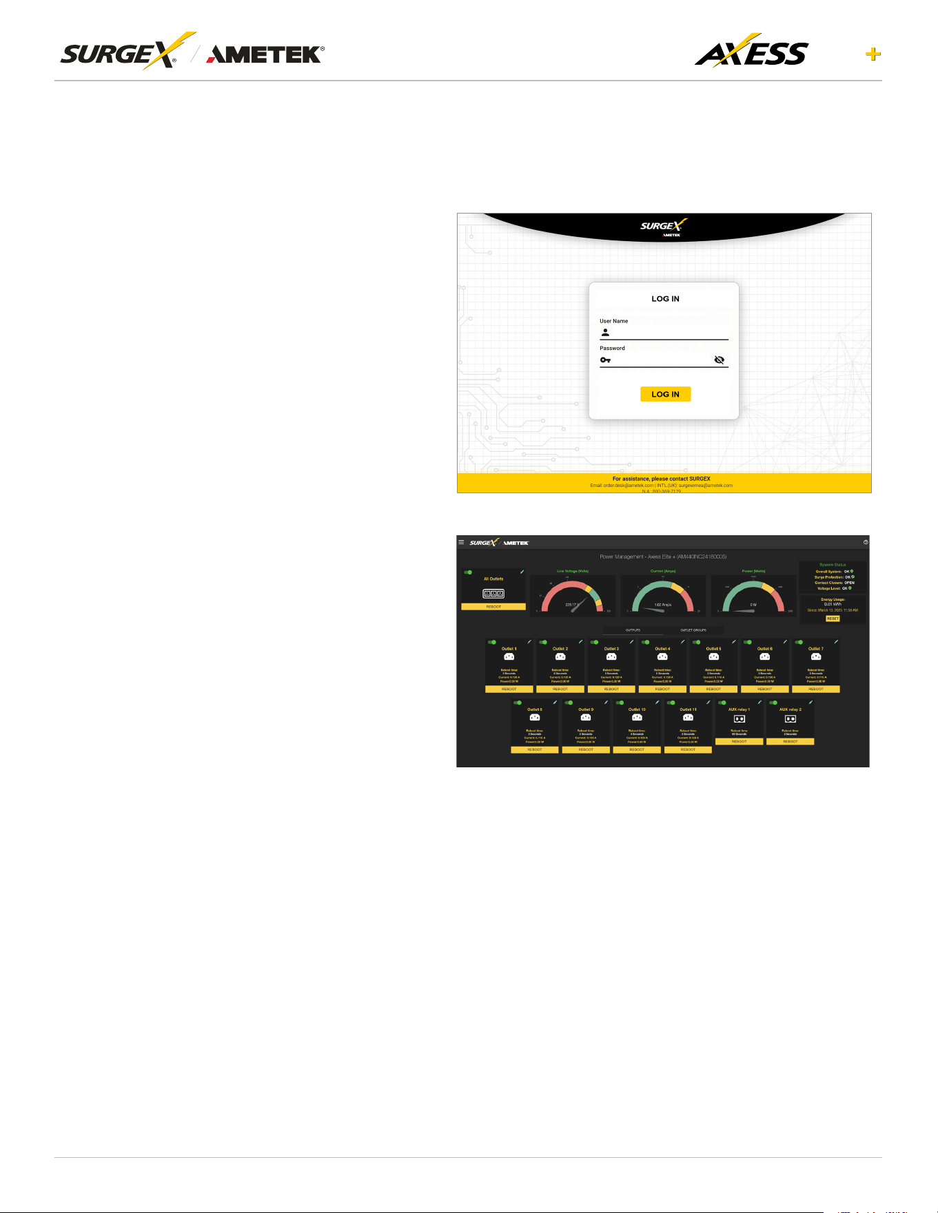
4.1 Login
The Login page is the rst page
displayed when a web browser makes a
connection to the Axess ELITE+. Enter
a valid username and password in the
“Username”and“Password”elds,and
press “Login” to log in.
4.2 Power Management
The Power Management page provides
information and status for the Axess
ELITE+ and individual outlets, as well
as basic control of each outlet and
auxiliary relay outputs. The top right
section of the page provides system
status. Contact Closure input status is
displayed.
9
ELITE
User Manual
©2025 AMETEK SurgeX | B01-00014 (REV A) Technical Support: 800-645-9721 | surgex.com
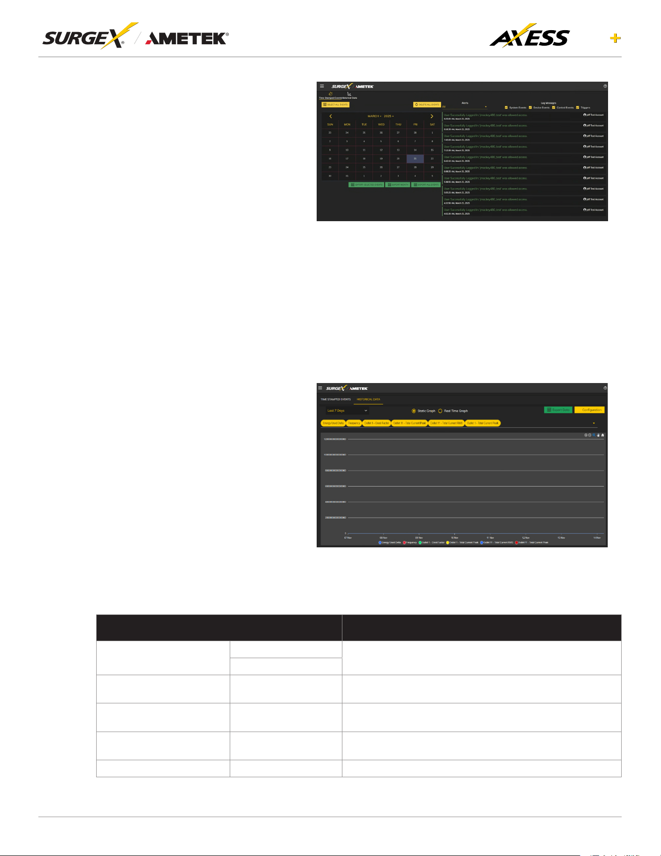
4.3 Reports
The Reports page displays data
collected by the Axess ELITE+ and
stored to its internal memory. The
data is presented in two groups: Time
Stamped Events and Historical Data.
Time Stamped Events are recorded,
with a date and time of occurrence when
a condition meets established criteria.
Axess ELITE+ uses a Real Time Clock
(RTC) synced to an Internet time server
and backed up by an internal battery.
For the most accurate time stamps
and to eliminate clock drift, we suggest
verifying the NTP connection.
The types of events which may be
recorded are:
• Triggers
• Power Outage
• Network Events
• Outlet Changes
• Shutdown Events
• Firmware Upgrades
Historical Data is a record of measured electrical parameters and may be adjusted to sample certain
itemsatspecicintervals.Theavailableparametersare:
HISTORICAL PARAMETERS DESCRIPTION
Voltage
Line -Neutral
The measured voltagebetween the conductors during the
measurement period.
Neutral-Ground
Voltage Neutral
ground peak
Neutral-Ground Peak
The measured peak voltage between the conductors during
the measurement period.
Total Current of all outlets Total current
The measured total current of all the outlets during the
measurement period.
Frequency Frequency
The measured input frequency during the measurement
period.
Power Factor of all Outlets Power Factor The measured power factor during the measurement period.
10
ELITE
User Manual
©2025 AMETEK SurgeX | B01-00014 (REV A) Technical Support: 800-645-9721 | surgex.com
HISTORICAL PARAMETERS DESCRIPTION
Total Energy of all Outlets Total Energy
The measured energy of all outlets during the measurement
period.
Internal Temperature
The measured Internal temperature during the measurement
period.
Each Outlet Current Each Outlet The measured RMS current during the measurement period.
Each Outlet Active Power Each Outlet The measured active power during the measurement period.
Each Outlet Peak Current Each Outlet The measured peak current during the measurement period.
Each Outlet Power Factor Each Outlet The measured power factor during the measurement period.
Each Outlet Crest Factor Each Outlet
The maximum crest factor calculated during the
measurement period.
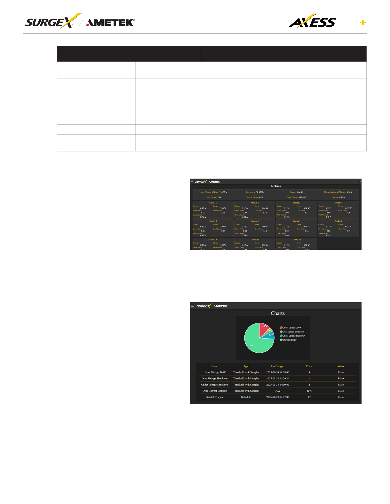
4.4 Power Monitoring
Power Monitoring page provides real-
time data collected by the Axess ELITE+.
It presents details regarding the total
outlet power and the power distributed
through each outlet. Key metrics
displayed include Line-Neutral Voltage,
Neutral-Ground Voltage, Current,
Frequency, Power Consumption, Crest
Factor, and Power Factor.
4.5 Chart
The Chart page provides a
comprehensive log of all user-dened
triggers activated by the Axess ELITE+.
It includes detailed information such as
the trigger name, type, last activation
timestamp, activation count, and
current status. Additionally, a pie chart
offers a visual representation of the
relative frequency of trigger activations,
providing a clear comparison of trigger
activity.

11
ELITE
User Manual
©2025 AMETEK SurgeX | B01-00014 (REV A) Technical Support: 800-645-9721 | surgex.com
4.6 Setup
CompletesetupandcongurationofAxessELITE+isprovidedvia6Setupwebpages.Eachsetup
page is described in the following sections. Each setup page has a save button at the bottom of
thepagewhichmustbepressedtokeepthecongurationchanges.Agreensuccessmessagewill
temporarily appear in the top right of the page when the settings are saved properly.
SETUP
Setup Page Description
DEVICE Congurebasicdeviceparameters
DeviceConguration Conguresettingsforvisualfeedbackandpowerupprocedure
OutletConguration Congurecontrollableoutletsettings
OutletGroupConguration Create, Edit, or delete outlet groups
Date/ Time Settings CongureNTPserverorsetmanualtime
NETWORK Congurenetworksettings,includingthenetworkadapterandtimekeeping
NETWORK ADVANCED Congureadvancedmonitoringandsecuritysettings
SNMP CongureSNMPconnectionandcommunicationsettings
802.IX Settings Congureauthenticationsettingsand/orviewconnectionlogs.
LDAP Client Settings CongureLDAPauthenticator,options,andtestconnection
Syslog Settings CongureSyslogserversettings
USERS Congureandmodifyuseraccounts.
TRIGGERS Create and modify Triggers
Threshold with Samples Conguretriggersbasedonmeasurements
Auto Ping ConguretriggersbasedonpingingIPaddresses
Schedule Conguretriggersbasedontime
Contact Closure (CC) Conguretriggersbasedoncontactclosurestatus
SEQUENCES Create and modify custom Sequences
12
ELITE
User Manual
©2025 AMETEK SurgeX | B01-00014 (REV A) Technical Support: 800-645-9721 | surgex.com
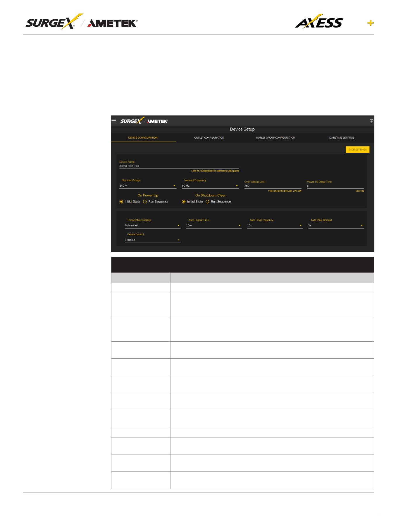
4.6.1 Device Setup
TheDeviceSetuppageallowsforthespecicationofbasicdeviceparameters.
4.6.1.1 DeviceConguration
The Device Conguration tab allows for the specication of visual feedback and
device initialization.
DEVICE CONFIGURATION
Item Description
Device Name SpeciesthenamelabeltobeassociatedwiththisAxessELITE+device.
Nominal Voltage
Speciestheexpectedvoltageontheinputreceptacle.Thisselection
does NOT change any settings for over/under voltage shutoff. This is only
for visual coloring on gauges.
Nominal
Frequency
Speciestheexpectedfrequencyontheinputreceptacle.Thisselection
does NOT change any settings for triggers. This is only for visual coloring
on gauges.
Over Voltage Limit
Based on the type of device, the range of the over voltage limit can be
adjusted.
Power-Up Delay
Time
Speciestheamountoftimeinsecondsbywhichtostaggerthemanual
turning on of multiple outlets when applying the initial state.
On Power Up
Specieswhethertosetoutletstoinitialstatesrunapredenedsequence
when Axess ELITE+ device powers up, or the hard reset button is pushed.
On Shutdown
Clear
Specieswhethertosetoutletstoinitialstatesrunapredenedsequence
when Shutdown state clear.
Temperature
Display
SpecieswhethertodisplaytemperatureindegreeFahrenheitorCelsius.
Auto Logout Speciesthewebsecuritytimeoutinminutes.
Auto Ping
Frequency
SpecieshowfrequenttheAxessELITE+devicewillsendpingstoanIP
Address or Hostname in an auto ping trigger.
Auto Ping Timeout
SpeciestheamountoftimetheAxessELITE+devicewillwaitforaping
response before calling the attempt a failure.
Device Control
Speciesiftheuserhaspermissiontocontroldevicefromcloudifitis
enabled and vice versa if disabled.
13
ELITE
User Manual
©2025 AMETEK SurgeX | B01-00014 (REV A) Technical Support: 800-645-9721 | surgex.com
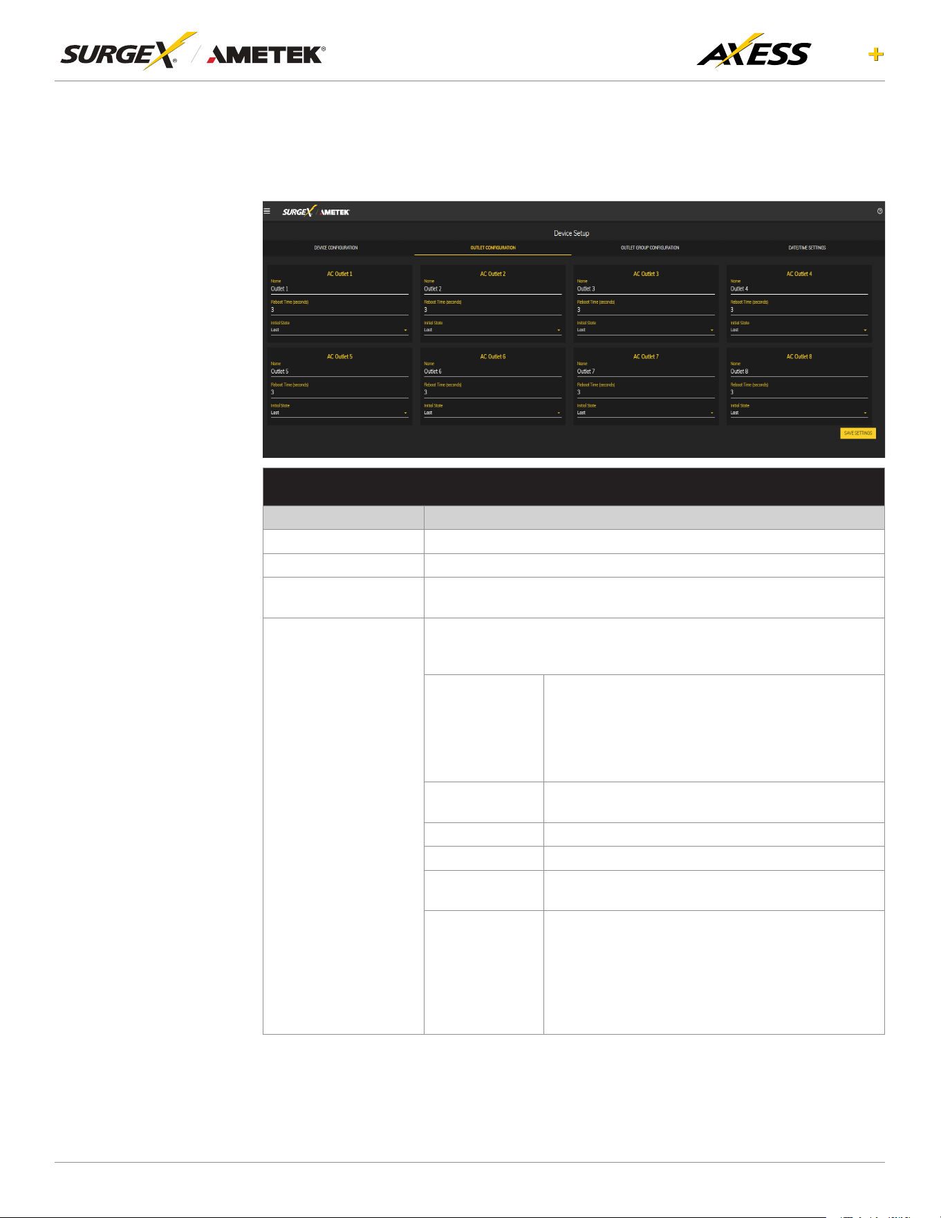
4.6.1.2 OutletConguration
TheOutletCongurationtaballowsforthespecicationofuniquenamesandreboot
timesperoutlet.Thecongurationforinitialstateperoutletisalsohere.
OUTLET CONFIGURATION
Item Description
Outlet Description Axedshortphrasethatreferencesaphysicalfeature.
Outlet Name SpeciesthenamelabeltobeassociatedwiththisOutlet
Reboot Time
Number of seconds that the device will wait in between turning an
outlet off and turning the outlet back on during a reboot command.
Initial State
The state that an outlet will assume during start up or after a shutdown
clears,iftheinitialstatesettingisselectedintheDeviceConguration
tab. Options are as follows:
Always On
Regardless of other settings, this outlet will always
be on. Ignores Shutdown state and deselecting
InitialStateintheDeviceCongurationtab.Outlet
ignores user commands to reboot or power off. The
only thing that will kill power with this selected is a
hard reboot, or of power outage.
Always Off
The opposite of Always On, this setting will never
allow an outlet to pass power
On The outlet will start in an On state.
Off The outlet will start in an Off state.
Last
The outlet will assume the last state it was in.
(Factory Default
Reboot Only
The outlet will act like the On state but will ignore
user commands to power off. This outlet will only
respond to reboot commands. Useful for network
appliances that may need to be rebooted, but
otherwise want to be on all the time. Using this
setting, the outlet will still turn off during Shutdown
state.
14
ELITE
User Manual
©2025 AMETEK SurgeX | B01-00014 (REV A) Technical Support: 800-645-9721 | surgex.com
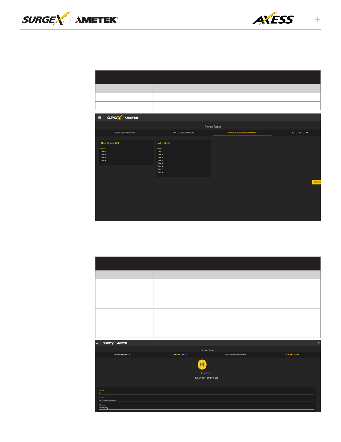
4.6.1.3 OutletGroupConguration
The outlets can be grouped under unique names as per the user requirements. User
can modify/add/delete groups.
OUTLET GROUP CONFIGURATION
Item Description
Group Name Speciesthenamelabeltobeassociatedwiththeoutletgroup.
Member Name Speciestheoutletmembersofthisoutletgroup.
4.6.1.4 Date/Time Settings
The Date/Time Settings tab allows for the specication of visual feedback, and
device initialization.
DATE/TIME CONFIGURATION
Item Description
Server Time Returns the device's internal time based on the local time zone.
Set Time
SpeciesthemethodforsettingthetimeintheAxessELITE+device.
Options for this setting are NTP or manual. NTP will use the NTP
Server option to automatically sync the device time every day.
Time Zone
SpeciesthedesiredtimezoneadjustmentfortheAxessELITE+
device.
NTP Server
SpeciesthehostnameorIPaddressoftheNTPservertousefortime
synchronization.
15
ELITE
User Manual
©2025 AMETEK SurgeX | B01-00014 (REV A) Technical Support: 800-645-9721 | surgex.com
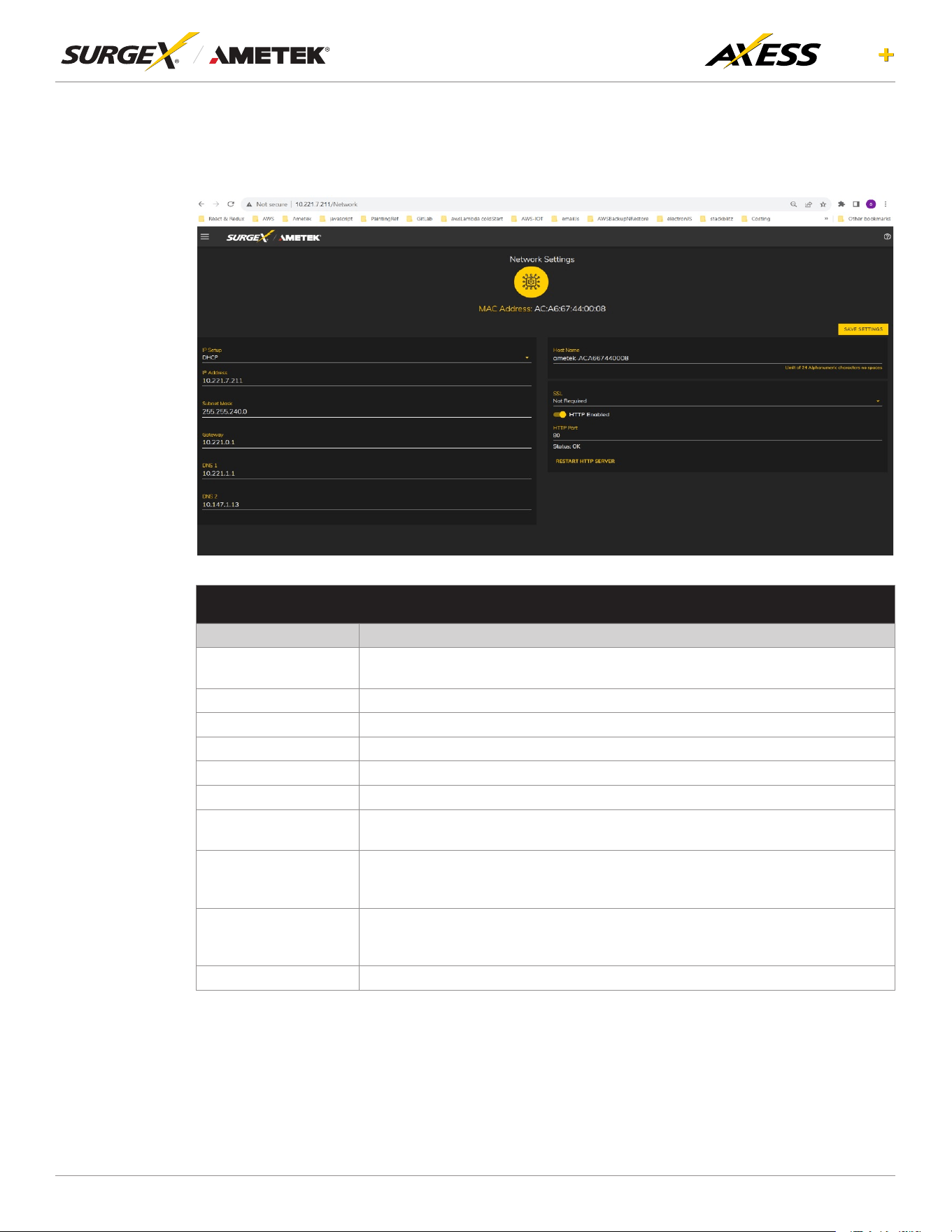
4.6.2 Network Setup
TheNetworkSetuppageallowsforthespecicationofnetworksettings,includingthenetwork
interface.
NETWORK CONFIGURATION
Item Description
IP Setup
SpeciesifthedevicewillhaveastaticIPAddressorwilldynamicallybeassigned
network settings through DHCP.
IP Address Current IP Address of the network interface on the RJ-45 Ethernet port
Subnet Mask Current Subnet Mask of the network interface on the RJ-45 Ethernet port.
Gateway Current Gateway of the network interface on the RJ-45 Ethernet port
DNS 1 Current DNS1 of the network interface on the RJ-45 Ethernet port.
DNS 2 Current DNS2 of the network interface on the RJ-45 Ethernet port.
Host Name
AcongurableuniquenametobeusedtoaccessthedeviceinsteadofanIP
Address.
SSL
SpecieswhetherthewebserverwillbeSSLencrypted(HTTPS)ornot(HTTP).
Thedefaultcerticateisself-signedandwillrequiretheusercontinuethrougha
safetynoticationifacustomsignedcerticateisnotuploadedtothedevice.
HTTP Enabled
Speciesifthewebserverisenabledordisabled.
NOTE: If disabling the web server, the web interface end REST API will be
disabled, only limited functionality over SNMP will remain it enabled.
HTTP Port Port number to use for the web server.
16
ELITE
User Manual
©2025 AMETEK SurgeX | B01-00014 (REV A) Technical Support: 800-645-9721 | surgex.com
4.6.3 Network Advanced Setup
TheNetworkAdvancedSetuppageallowsforthespecication ofmoreadvancednetwork
security and monitoring options.
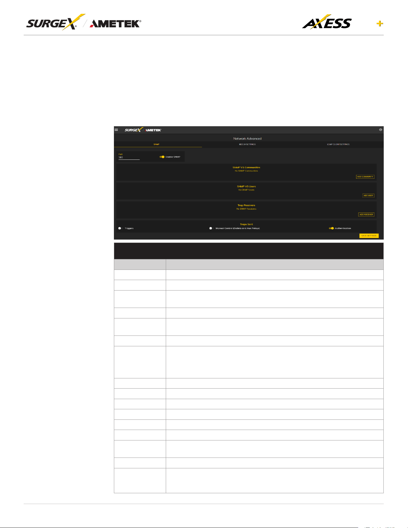
4.6.3.1 SNMP
The SNMP tab allows for the specication of parameters for the SNMP agent,
supporting V1 through V3.
SNMP SETUP
Item Description
Enable SNMP SpecieswhethertoenabletheSNMPagent.
Port
SpeciestheportnumberfortheSNMPagent.161isthestandardSNMPport.
SNMP V1
Communities
Is a table of all SNMP communities, supporting SNMP V1 at a minimum.
Name SpeciestheCommunitynameforreadand/orwriteaccess.
Source
Speciesanunrequiredwhitelist.Ifrequestsarenottobelteredby
hostnameorIPAddress,thiseldcanbeleftblank.
Access Speciesthetypeofaccessallowedbythecommunity.
SNMP V3
users
IsatableofUsersspecicallyforSNMPV3authorization.Usersherewillnot
apply to the REST API, and REST API users will not be able to authenticate
viaSNMPV3withoutredeningtheircredentialshere.SNMPcredentials
cannot be authenticated using the LDAP Client.
Name The name or username for authorization.
Authorization Type of encryption used per user. Options are DES or MD5.
Access Type of access per user. Options are Read Only or Read/Write.
Passphrase Passphrase or password for the user.
Trap Receivers Is a table of all the destinations for SNMP traps.
Name The name of the community for traps.
Host Name
The hostname or IP address of the SNMP Manager that is going to receive
traps.
Port The port number that the SNMP Manager is listening for traps on.
Traps Sent
Specieswhichspecictrapsaretobesent.Triggerssendtrapsfor
Triggering and Clearing. Manual Control sends traps for outlet state changes,
and Authentication sends traps for failed authentication attempts.

17
ELITE
User Manual
©2025 AMETEK SurgeX | B01-00014 (REV A) Technical Support: 800-645-9721 | surgex.com
4.6.3.2 802.1X Settings
The802.1XSettings taballows forthespecication of802.1Xauthenticationand
debugging of errors as they may arise.
802.1X SETTINGS SETUP
Item Description
802.1x Enabled
Enables the 802.1x authentication client. This does not require the
user to have a unique password for Axess Elite+ device. Network login
credentials can be used.
Show Log Messages
Opens and hides a table with date/time coded 802.1x related
messages for debugging an authentication failure.
Authentication Type
Specify the authentication method used during the 802.1x negotiation.
Different authentication options and settings will be displayed based on
the selected Authentication Type.
18
ELITE
User Manual
©2025 AMETEK SurgeX | B01-00014 (REV A) Technical Support: 800-645-9721 | surgex.com
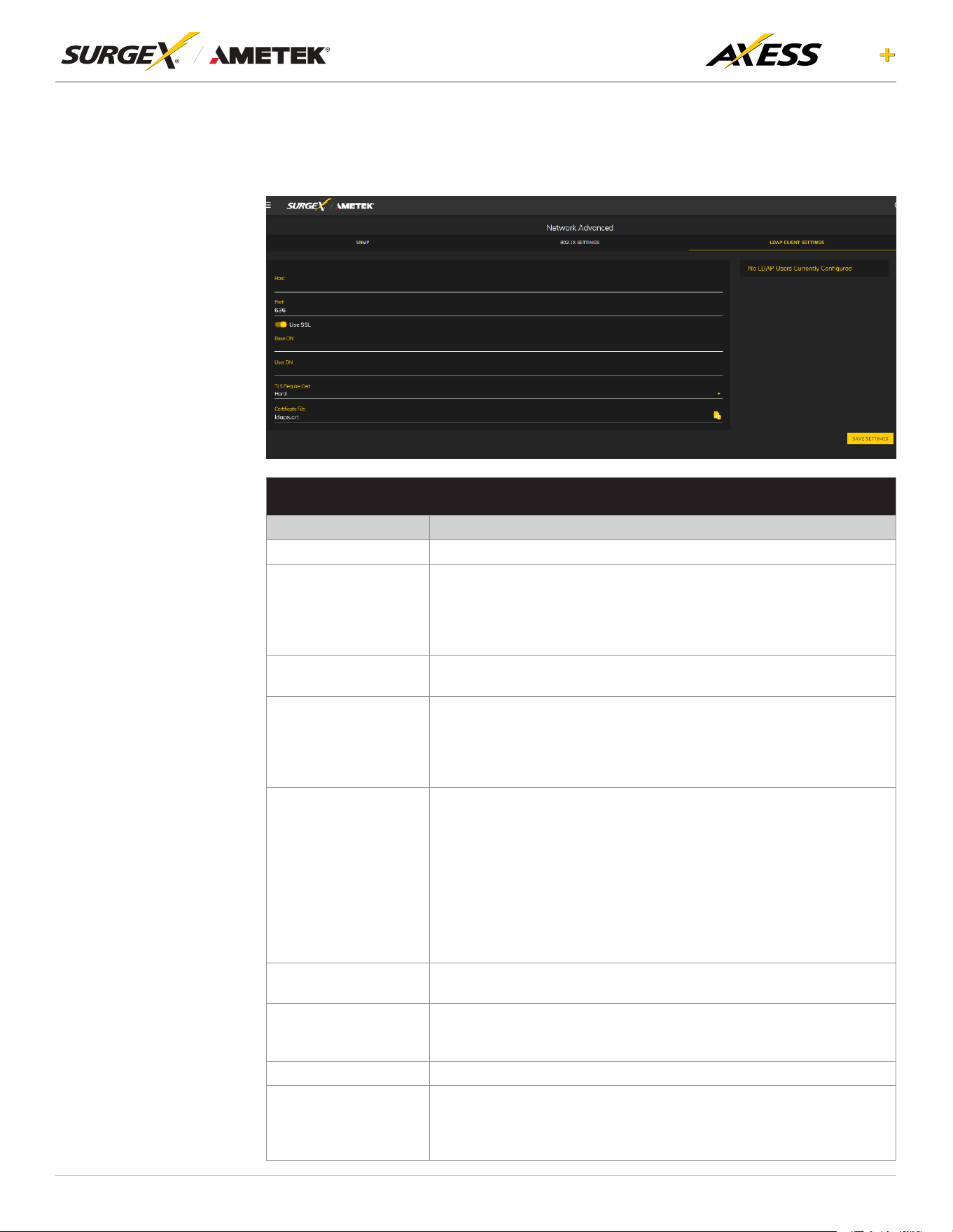
4.6.3.3 LDAP Client Settings
TheLDAPClientSettingstaballowsforthespecicationoftheLDAPAuthentication
server and authentication method, and a test interface to test the server setup.
LDAP CLIENT SETTINGS SETUP
Item Description
Host The hostname or IP address of the LDAP server
Use SSL
A switch that will enable or disable SSL when attempting to connect
to the LDAP server. This is a separate option than the port number, in
the case that a site is using a nonstandard port for authentication, but
still wants the ability to specify encryption. We always suggest using
encryption when using LDAP.
Base DN
The base point in the directory tree where the user distinguished name
search will begin.
User DN
The distinguished name of a user that will be used to authenticate.
Multiple users are supported by using macros. For example, in the
above image, the username test User attempts to log in, and the User
DNpullsthename"TestUser"fromtheuser'sdenitionforuseinthe
authentication to replace the string %Full Name%.
TLS Require Cert
ThisspecieshowtohandleservercerticatesduringTLS
negotiations.Never:theclientneveraskstheserverforacerticate.
Allow:theclientwillaskforacerticate,ifnoneisprovidedthesession
proceedsnormally.Ifacerticateisprovidedbuttheclientisunableto
verifyit,thecerticateisignoredandthesessionproceedsnormally,
asifnocerticatehadbeenprovided.Try:thecerticateisrequested,
andifnoneisprovided,thesessionproceedsnormally.Ifacerticate
isprovidedanditcannotbeveried,thesessionisimmediately
terminated.Demand:thecerticateisrequested,andavalidcerticate
must be provided, otherwise the session is immediately terminated.
CerticateFile
ThisisthecerticatethatwillbesenttotheLDAPServerwhen/if
requested.
User Name
TheinformationforauserthatisdenedintheUserspage.The
rstpart(name),isaccessiblebythe%FullName%macro,andthe
second part (username) is accessible with the %User Name% macro.
Password ThepasswordforthegivenusertotesttheLDAPserverconguration.
Test User
A button to send an authentication request using the given settings for
the user and password above. NOTE: Settings should be saved using
the "Save Settings" button at the bottom of the page before testing a
congurationchange.
19
ELITE
User Manual
©2025 AMETEK SurgeX | B01-00014 (REV A) Technical Support: 800-645-9721 | surgex.com
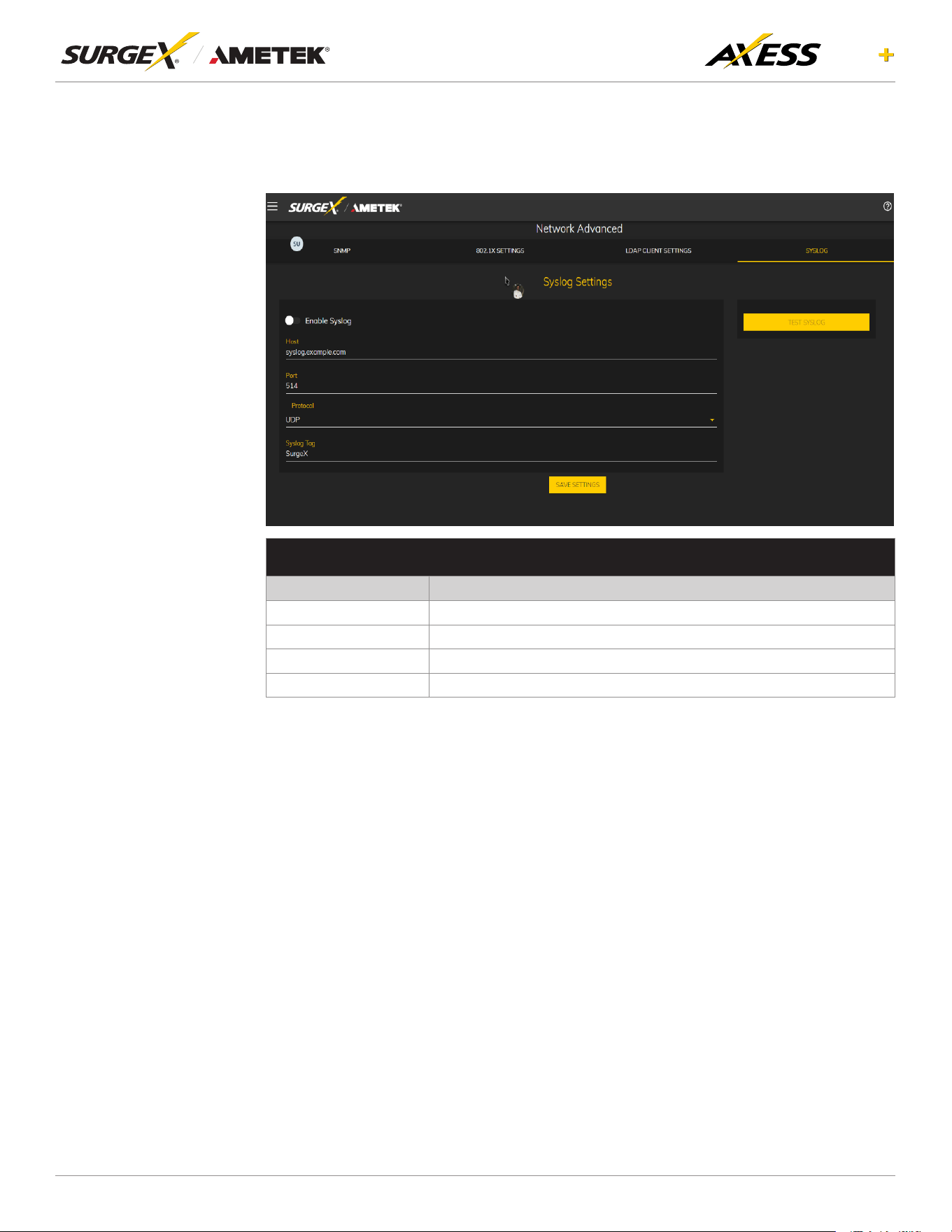
4.6.3.4 Syslog Settings
The Syslog Settings tab allows for the specication of the SyslogAuthentication
server and authentication method, and a test interface to test the server setup.
SYSLOG SETTINGS SETUP
Item Description
Host The IP address or name of the Syslog server
Port Listening port used by syslog server
Protocol Supported protocol by syslog server
Syslog Tag Required syslog tag can be given
20
ELITE
User Manual
©2025 AMETEK SurgeX | B01-00014 (REV A) Technical Support: 800-645-9721 | surgex.com
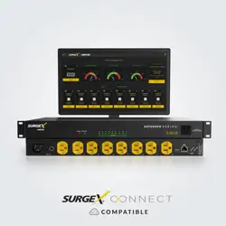
4.6.4 Cloud Setting
To start the device registration process, click on the Cloud
Settings menu. Follow these steps carefully: First, ensure
the device has the latest rmware. Next, conrm you
have created an account on www.surgexconnect.com.
Finally, log in using your registered credentials. Next,
click on the “Register Device” button to initiate the device
registration. Note that the Device Registration Page will
not be visible if the device is already registered. Upon
successful registration, you will be redirected to a page
where you can view basic device information on the
cloud. If you ever need to de-register your device, click
on the “De-Register” button. Only use this option if you
want to remove your device from the cloud.
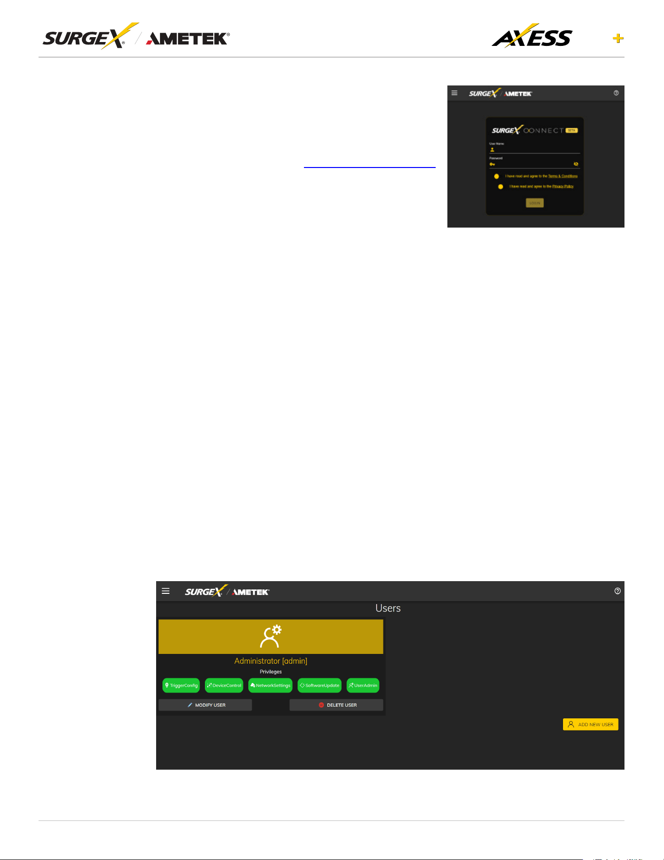
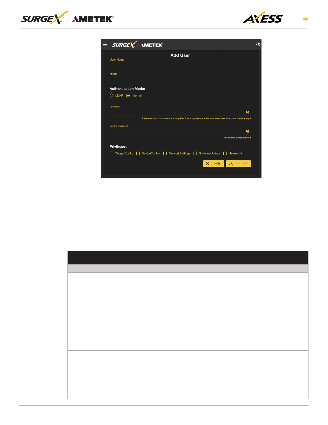
4.6.5 Users
To add a new user, click the Add New User button. You can edit/add or delete user accounts
on this screen. Each user will have a unique name, username, authentication mode, and may
be assigned access to specic features. For each user, you can select theAuthentication
Mode as either LDAP or internal. You can also set up Privileges for each user, which include:
• TriggerCong:Allowstheusertoconguretriggers.
• Device Control: Grants the user control over device outlets.
• Network Settings: Permits the user to modify network settings.
• Software Update: Enables the user to update software.
• UserAdmin: Provides administrative privileges over user accounts.
21
ELITE
User Manual
©2025 AMETEK SurgeX | B01-00014 (REV A) Technical Support: 800-645-9721 | surgex.com
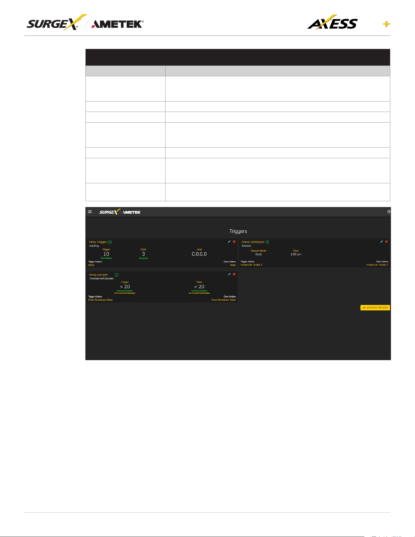
4.6.6 Triggers Setup
TheTriggersSetuppageallowsforthemodicationofTriggers.Triggersdeneeventlogging
parametersandallowcongurationtoautomaticallycontrolandprotectconnectedequipment.
Triggers are categorized into four types, autoping, Threshold with Samples, Schedule, and
Contact Closure but all have the same possible actions. Actions can either be on the onset
(Trigger/Alarm Actions) or offset (Clear Actions) of a trigger. All Triggers are logged, along with
the associated actions.
TRIGGER TYPES
Item Description
Threshold with Samples
Uses measurements over an allotted time to take an action. This trigger type
iscongurabletoactveryquicklyorveryslowlydependingonenvironmental/
system needs.
Thresholds include:
• Line Voltage
• N-G Voltage
• Current
• Temperature (Axess Elite+ Internal temperature)
• External Temperature (I2C sensor temperature)
• Frequency
• Average Power
• Crest Factor
• Power Factor
Auto Ping
Issues a ping function on a periodic basis to determine if an IP asset is
accessible.
Schedule
Uses the device time to issue a one time or periodic command. We suggest
ensuring the NTP server is updating correctly to use the schedule trigger.
Contact Closure
The actions to be executed upon closing or opening of the contact closure
inputmaybedenedasvariousUserTriggersontheTriggersSetupweb
page.
22
ELITE
User Manual
©2025 AMETEK SurgeX | B01-00014 (REV A) Technical Support: 800-645-9721 | surgex.com
ACTION TYPES
Item Description
None
Do not take any action, only log the event. This is useful as a Clear Action
when an action should persist, or for both Alarm and Clear actions when just
logging the event is desired.
Power On Poweronaspecicoutletiftheoutletcongurationallowsit.
Power Off Poweroffaspecicoutletiftheoutletcongurationallowsit.
Reboot
Rebootaspecicoutletiftheoutletcongurationallowsit.Ifanoutletis
already off when this command is issued, the outlet will simply turn on after the
outletspecicrebootdelaytime.
Run Sequence Runaspecicsequence.
Enter Shutdown State
Put the device into a shutdown state. This state turns off all outlets (unless
theyareconguredforalwayson).Theonlywaytoclearashutdownstate,is
another trigger, a button on the web interface, or a REST API command.
Clear Shutdown State
Clear the device's shutdown state. Clearing the device's shutdown state will
causetheoutletstofollowthelogicdenedbytheOnShutdownClearsetting.
23
ELITE
User Manual
©2025 AMETEK SurgeX | B01-00014 (REV A) Technical Support: 800-645-9721 | surgex.com
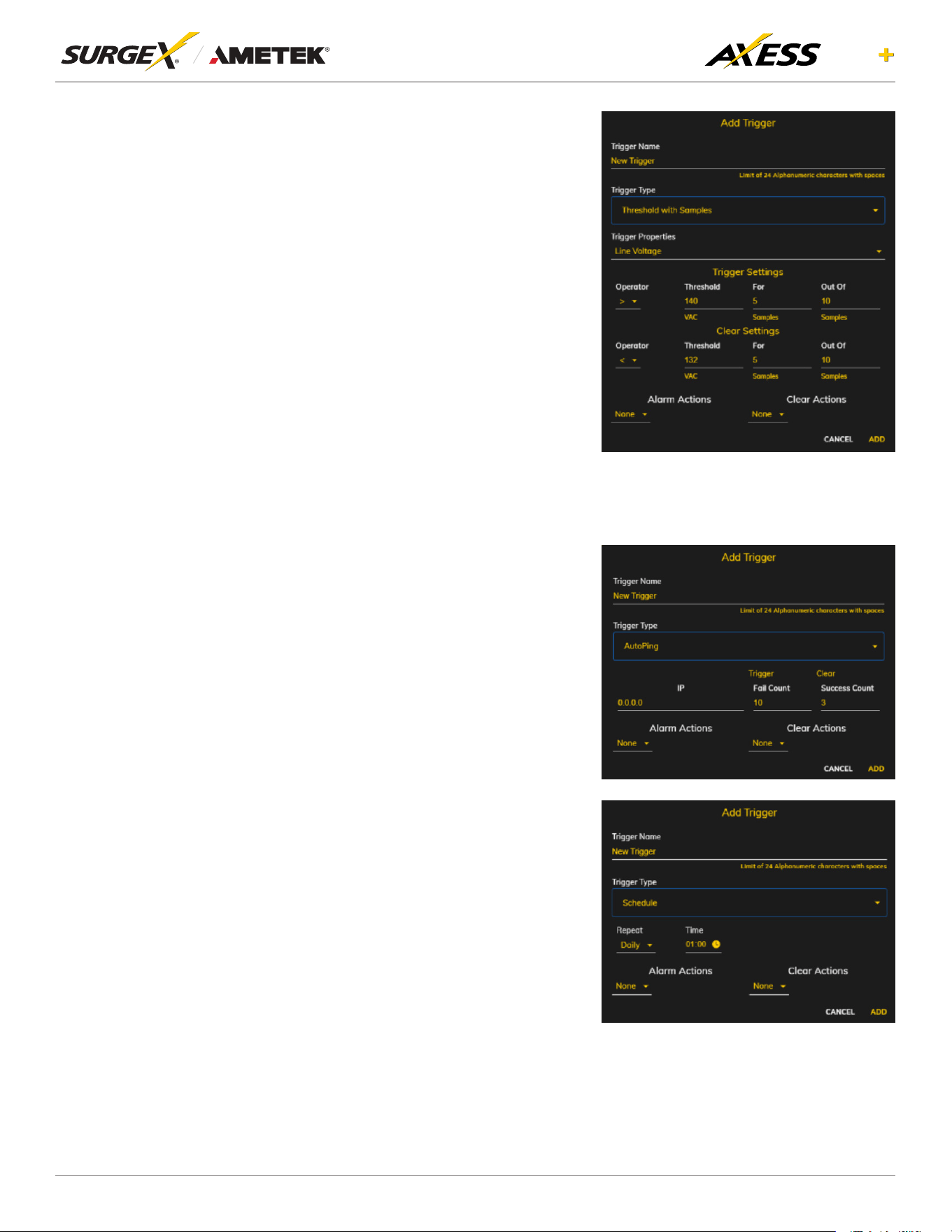
4.6.6.1 Threshold with Samples
The Threshold with Samples trigger uses
several measurements to decide when
toact.Thetriggercanbeconguredto
act quickly, or slowly, depending on the
number of measurement samples used.
A new sample is available every 50ms,
with the minimum samples being used
for a trigger being 1 sample, and the
maximum being 20 samples. Threshold
with Samples triggers are evaluated
every time a new sample is available.
Based on the below “New Trigger”
example below, the trigger will alarm
or turn on after 5 of any consecutive 10
samples are above 140V.
4.6.6.2 Autoping
The Autoping trigger uses a ping
commandonaperiodicbasisdenedin
thedevicesettingstotestifaspecicIP
address will respond. This trigger type is
useful if there is a problematic piece of
equipment that becomes unresponsive,
or if internet connectivity is inconsistent.
4.6.6.3 Schedule
The Schedule trigger uses the internal
time of the Axess ELITE+ to easily
congure single and recurring events
based on time. Only Alarm Actions are
used for this trigger.
24
ELITE
User Manual
©2025 AMETEK SurgeX | B01-00014 (REV A) Technical Support: 800-645-9721 | surgex.com
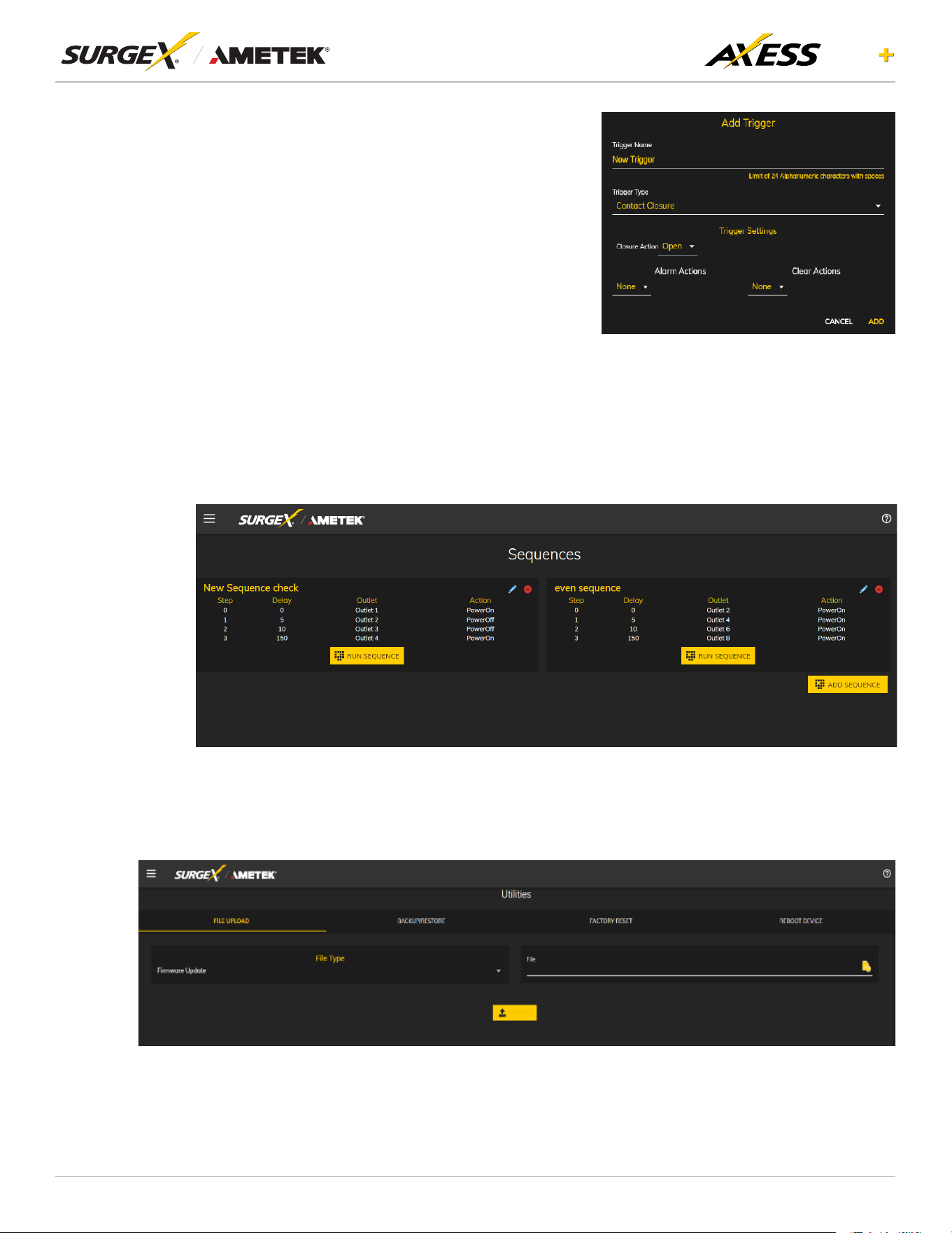
4.6.6.4 Contact Closure
Connect a contact closure control input
(if any) to the 2 pins of the second
terminal block. Relays, switches, and
push buttons are all suitable input types.
The actions to be executed upon closing
or opening of the contact closure input
maybedenedasvariousUserTriggers
on the Triggers Setup web page.
4.6.7 Sequences Setup
TheSequencesSetuppageallowsforthecreationandmodicationofsequences.Asequence
isasetofactionstobetakeninaspecicorder,andwithaspecieddelaytimebetweeneach
step. Using sequences avoids manually performing each action, or turning each outlet on or
off, individually.
4.7 Utilities
Axess ELITE+ contains several utilities to ease the conguration and deployment that may be
performed on a per unit basis through several web pages.
25
ELITE
User Manual
©2025 AMETEK SurgeX | B01-00014 (REV A) Technical Support: 800-645-9721 | surgex.com
FILE UPLOAD
Item Description
Firmware Update Select this option to upload Firmware File.
CongurationFile SelectthisoptiontouploadanewCongurationFile.
SNMPConguration SelectthisoptiontouploadanewSNMPcongurationFile.
Power Board Firmware Update Select this option to upload the Power Board Firmware File.
LDAPCerticate SelectthisoptiontouploadthecerticaterequiredtoconnecttoLDAPserver.
HTTPSCerticates SelectthisoptiontouploadnewHTTPScerticates.
SSH Public Key SelectthisoptiontouploadnewSSHPublicKey,thislemustbeinpubformat.
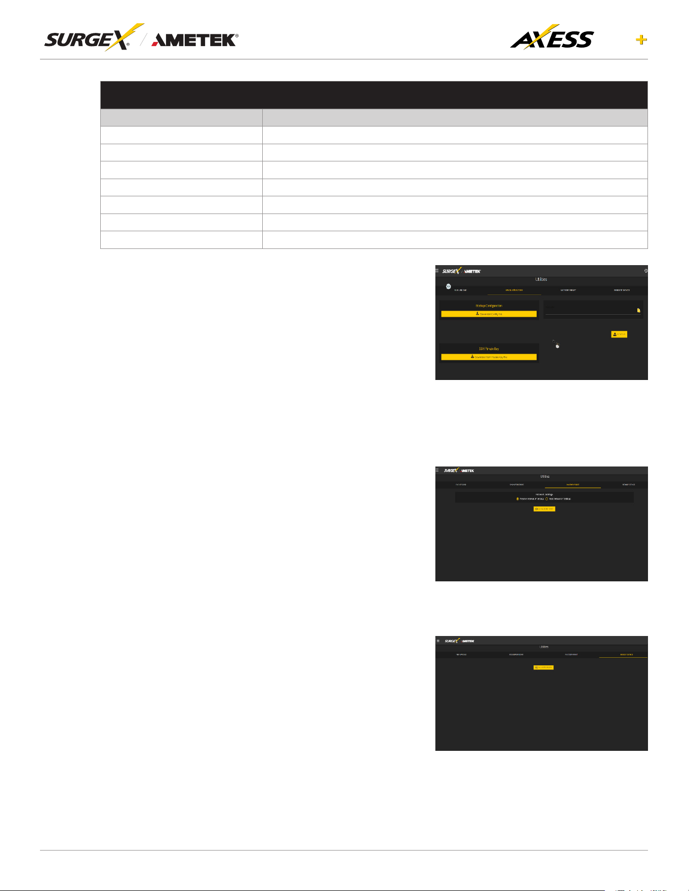
4.7.2 Backup/Restore
Thecurrentcongurationmaybesavedtoale
and downloaded for archival. Previously stored
congurations may be applied to other units
to easily mass congure a larger deployment.
IP Settings will not be saved in the Backup
Conguration.
Axess ELITE+ also has a provision for downloading
theSSHprivatekeyleforremoteloggingonthe
device
4.7.3 Factory Reset
Factory default settings may be applied through
the web interface.
• Option to keep or reset network IP settings.
• Web Server settings will be reset. A custom
port number will be reset to 80, and SSL will
be disabled by default.
4.7.4 Soft Reboot
Adds the ability to reboot the Axess ELITE+
processor. A soft reboot will not change the
outlet state or disconnect power from connected
equipment. This request will add a message in
the event log “Rebooting Adapter Due to User
Request”.
26
ELITE
User Manual
©2025 AMETEK SurgeX | B01-00014 (REV A) Technical Support: 800-645-9721 | surgex.com
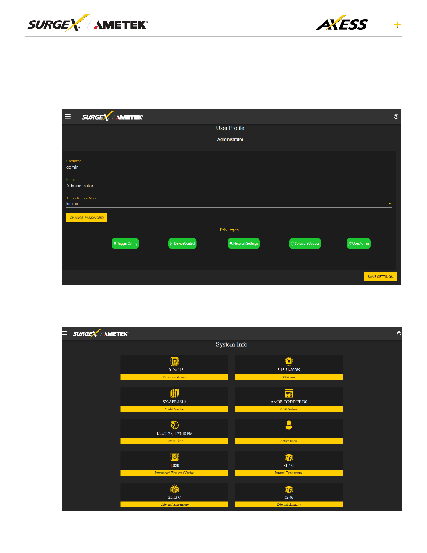
4.8 UserProle
The User Prole screen provides the current user’s information and allows them to change their
password. On this page, users can also edit their username, password, and view their privileges and
authenticationmode.Thisscreenhelpsuserstomanagetheirownprolesandmaintaintheiraccount
security.
4.9 System info
The System Info screen provides hardware and software information about the device and the number
of users connected to the device.

27
ELITE
User Manual
©2025 AMETEK SurgeX | B01-00014 (REV A) Technical Support: 800-645-9721 | surgex.com
5. Command Line Interface (CLI)
ManycongurationparametersmaybesetusingtheCommandLineInterface(CLI).TheCLIisaccessed
through the network using a SSH telnet client, or through the serial port (RS 232).
5.1 SSH
1. To log in to the SSH console, follow these steps:
2. Run the application.
3. Open the UI and navigate to Utilities.
4. Go to BACKUP/RESTORE and download the SSH Private Key.
5. Open the terminal and navigate to the folder containing the SSH Private Key.
6. Use the following command to log in to the SSH console:
ssh -T -i sshrsaPrivate <IP_ADDRESS>
5.2 RS 232 PORT
To access the RS-232 console, follow these steps:
1. Open Tera Term.
2. Connect to the RS-232 port.
3. Go to Setup and select Serial Port.
4. Set the speed to 115200.
5. Click on New Settings to connect.
6. Provide the login credentials:
• Login: admin
• Password: admin
28
ELITE
User Manual
©2025 AMETEK SurgeX | B01-00014 (REV A) Technical Support: 800-645-9721 | surgex.com
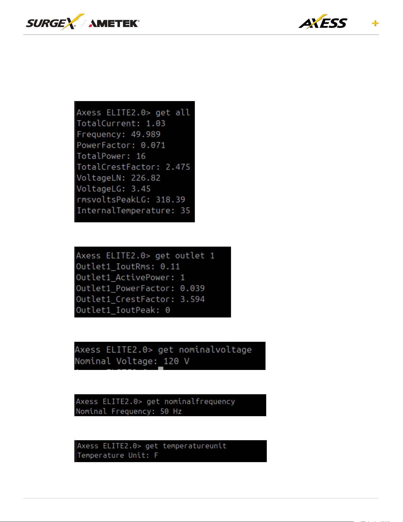
5.3 Commands
Once connected to either the SSH or RS232 consoles, users can execute the following commands to
retrieve and set device parameters:
• get all: Retrieves all available data from the device.
• get outlet 1: Retrieves the data of outlet 1.
• get nominalvoltage: Retrieves the nominal voltage setting of the device.
• get nominalfrequency: Retrieves the nominal frequency setting of the device.
• get temperatureunit: Retrieves the temperature unit setting of the device.
29
ELITE
User Manual
©2025 AMETEK SurgeX | B01-00014 (REV A) Technical Support: 800-645-9721 | surgex.com
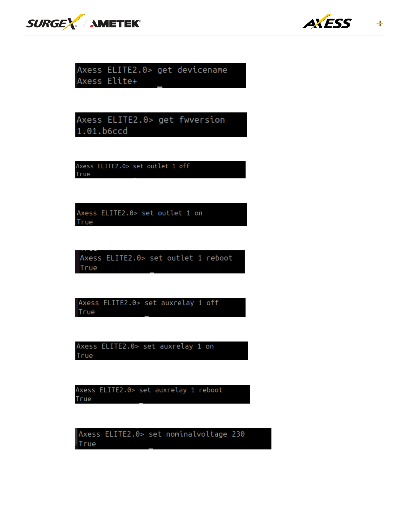
• get devicename: Retrieves the name of the device.
• getfwversion:Retrievesthermwareversionofthedevice.
• set outlet 1 off: Turns off outlet 1.
• set outlet 1 on: Turns on outlet 1.
• set outlet 1 reboot: Reboots outlet 1.
• set auxelay 1 off: Turns off Aux relay 1.
• set auxelay 1 on: Turns on Aux relay 1.
• set auxelay 1 reboot: Reboots Aux relay 1.
• set nominalvoltage: Sets the nominal voltage for the device.
30
ELITE
User Manual
©2025 AMETEK SurgeX | B01-00014 (REV A) Technical Support: 800-645-9721 | surgex.com
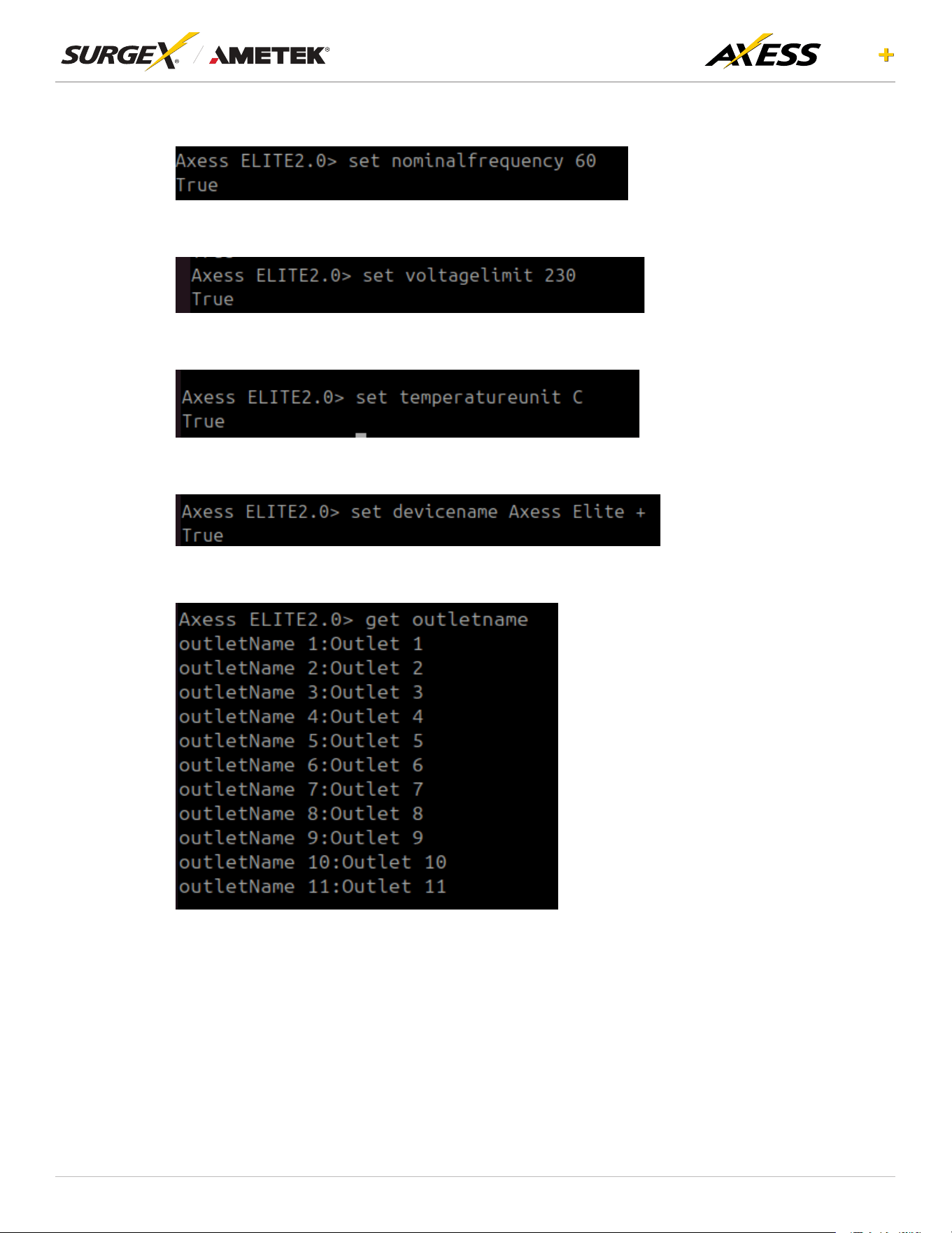
• set nominalfrequency: Sets the nominal frequency for the device.
• set voltagelimit: Sets the voltage limit for the device.
• set temperatureunit: Sets the temperature unit for the device.
• set devicename: Sets the name of the device.
• get outletname: Retrieves the name of all the outlets.
31
ELITE
User Manual
©2025 AMETEK SurgeX | B01-00014 (REV A) Technical Support: 800-645-9721 | surgex.com
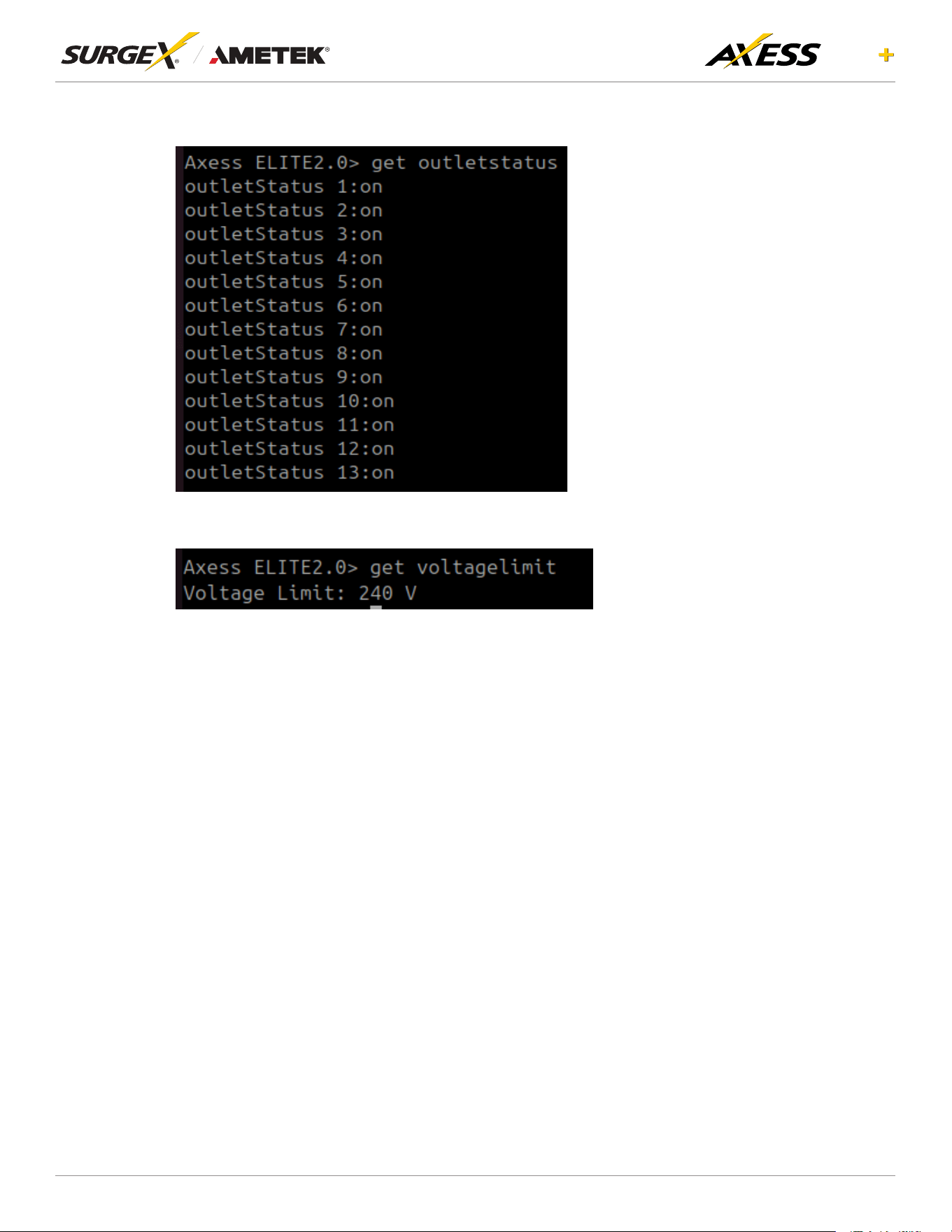
• get outletstatus: Retrieves the status of all the outlets.
• get voltagelimit: Retrieves the voltage limit of the device.
6. Security
Axess ELITE+ has been designed with security as a priority. All ports and features may be changed or
disabled.
6.1 Authentication
Axess ELITE+ supports basic and secure authentication for users and network connections.
6.1.1 802.1X
802.1X network authentication may be enabled for networks requiring supplicant authentication.
6.1.2 SSO (Single Sign-On)
Axess ELITE+ users may be congured to use either Internal or SSO (Single Sign-On)
authentication. Internal authentication uses basic usernames and passwords assigned by
the administrator on a per-unit basis. SSO authentication uses LDAP (Lightweight Directory
Access Protocol) to authorize users, and determine their level of privileges, using Microsoft®
Active Directory. While it is possible to use LDAP to authorize users without SSL encryption,
wesuggestonlyconguringtheconnectiontotheauthenticationserverusingSSLencryption
toplaintextnetworktrafc.
32
ELITE
User Manual
©2025 AMETEK SurgeX | B01-00014 (REV A) Technical Support: 800-645-9721 | surgex.com
6.2 Interfaces
6.2.1 Network Interface
Web Server: It is possible to enable and disable the internal web server, change the security
from none (HTTP) to TLS 1.2 (HTTPS), as well as change its port. These settings also apply
to the REST API.
SNMP: Axess ELITE+ supports SNMP V3 for secure communications, with the ability to
enable and disable.
7. Application Programming Interfaces (APIs)
AxessELITE+isdesignedforexiblecommunicationandintegrationwithdiversecontrolandmonitoring
platforms.
7.1 HTTP/HTTPS REST
Axess ELITE+ includes an extensive HTTP API (HTTPS when security is enabled) in JSON format.
Full protocol details are available at https://www.ametekesp.com.
7.2 Interfaces
SNMP V3 communications are intended to provide essential items for management. Read, Write,
Table, and Trap objects will be included. Full protocol details, and the SNMP MIB, are available at
https://www.ametekesp.com.
8. Part Numbers
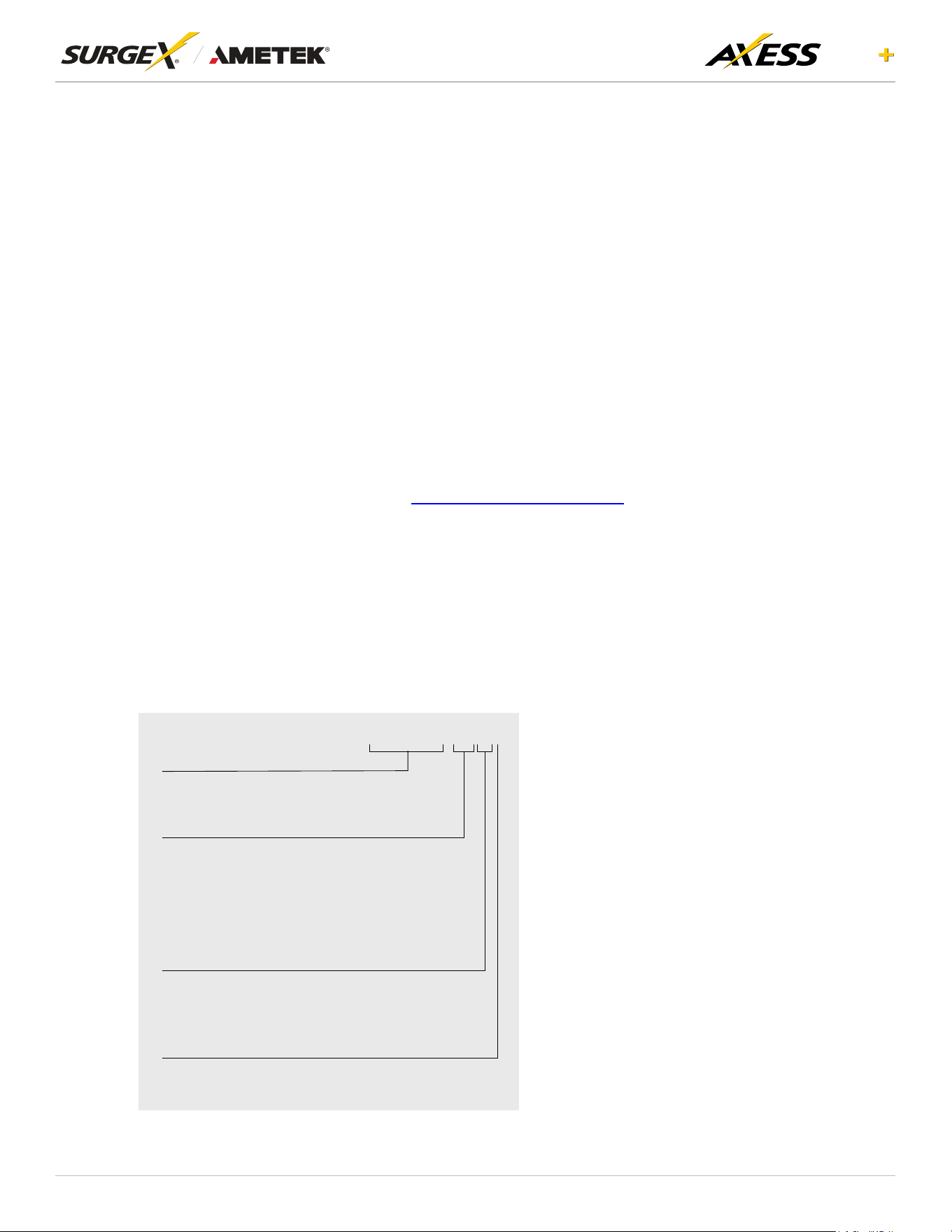
8.1 Part Number Scheme
SX-AEP-1011i
Product Line
SX-AEP SurgeX Axess ELITE+
Rated Current
10 10A Rated Current
15 12A Rated Current
16 16A Rated Current
20 16A Rated Current
Number of Receptacles
9 9 Receptacles (NEMA ONLY)
11 11 Receptacles (IEC ONLY)
NEMA / IEC Model
i IEC Model (240V)
blank NEMA Model (120V)
33
ELITE
User Manual
©2025 AMETEK SurgeX | B01-00014 (REV A) Technical Support: 800-645-9721 | surgex.com
9. Troubleshooting
1. Checking for power input issues -
a. Verify if the power source is functioning correctly and ensure that all connections are secure.
b. Verify the circuit breaker.
c. Verify the incoming line cord to the device is accidentally disconnected or if the mains plug is pulled
out from the wall receptacle.
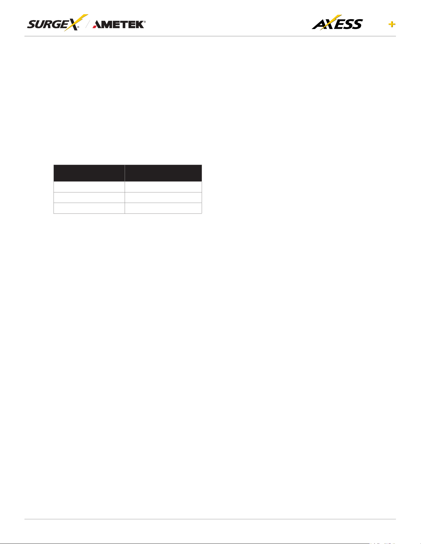
2. Diagnosing overloading issues - Check if the device is being overloaded by too many connected
devices or if there is a problem with the power distribution unit. Please refer to the Overload current
specicationtable.
RATED CURRENT MAXIMUM CURRENT
10A 15A
12A 15A
16A 20A
3. Inspecting for physical damage - Check for any signs of physical damage, such as bent pins, frayed
cords, or broken components.
4. Testingvoltagelevels-Verifythatthevoltagelevelsarewithintheappropriaterangeforthespecic
deviceandcheckforanyvoltageuctuationsorspikes.Impropermainsvoltagetothedevicemay
resultinre.
5. Checkingforrmwareorsoftwareissues-Ensurethatthermwareorsoftwareofthedeviceisup-to-
date and functioning correctly.
6. Investigating environmental factors - Check for any environmental factors that may be affecting the
device, such as extreme temperature or humidity.
7. Replacing a component or subsystem in the device without a trained technician may lead to device
malfunctionn.
8. Contacting customer support - If the above troubleshooting methods do not resolve the issue, the user
may be advised to contact customer support for further assistance.

34
ELITE
User Manual
©2025 AMETEK SurgeX | B01-00014 (REV A) Technical Support: 800-645-9721 | surgex.com
10.Specications
PARAMETER SX-AEP-159 SX-AEP-209 SX-AEP-1011i SX-AEP-1611i
AC Load Rating 12A @ 120V 16A @ 120V 10A @ 240V 16A @ 240V
No of Outlets - back 8 8 10 10
No of Outlets - front 1 1 1 1
Measurement
Accuracy
Voltage ± 2%
Current ± 5%
Power ± 7%
Energy ± 7%
Timestamp Accuracy ± 1%
Auxiliary Relay Control (2) 3 x screw terminal
Contact Closure (1) 2 x screw terminal
Temperature Sensor Input (1) 4 x screw terminal
Serial Port RS232 port
Network Port
10/100 Ethernet connection on Female RJ-45, Auto Negotiating with 10/100
network connections with Link and Activity LEDs
Micro USB
Weight 12.4 Lbs/5.6Kg 12.4 Lbs/5.6Kg 11.9 Lbs/5.4Kg 11.9 Lbs/5.4Kg
Dimensions
(Enclosure)
Height: 1.73”/44mm 1.73”/44mm 1.73”/44mm 1.73”/44mm
Width: 17.4”/442mm 17.4”/442mm 17.4”/442mm 17.4”/442mm
Depth: 11.8”/300mm 11.8”/300mm 11.8”/300mm 11.8”/300mm
Temperature Range: 100% Load 0 to 45 °C (32 - 113 °F)
Humidity Range 5% to 95% R.H. Non-condensing
Altitude 0 - 10000ft (0 - 3048meters)
Agency
Listings
Safety
CertiedtoUL62368-1 CertiedtoUL62368-1
CAN/CSA C22.2 No 62368-1:19,
3rd Ed
CE Mark
RoHS: Compliant WEEE
Prop 65
RoHS: Compliant
REACH: Compliant
Surge / EMI
FCC 47 CFR PART 15 SUBPART B
(Using ANSI C63.4-2014)
EN 55035:2017+A11:2020
EMC ICES-003 ISSUE 7
EN 55032:2015 + A1:2020
EN IEC 61000-3-2:2019 + A1:2021
EN 61000-3-3:2013 + A2:2021
Surge Protection Advanced Series Mode
IP protection class IPX0
AC Power System Type TN
Pollution Rating Pollution degree (PD) PD 2