
Technical Support and E-Warranty Certificate www.vevor.com/support
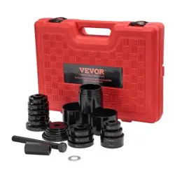
BUSHING EXTRACTOR
PRODUCT MANUAL
We continue to be committed to provide you tools with competitive price.
"Save Half", "Half Price" or any other similar expressions used by us only represents an
estimate of savings you might benefit from buying certain tools with us compared to the major
top brands and does not necessarily mean to cover all categories of tools offered by us. You
are kindly reminded to verify carefully when you are placing an order with us if you are
actually saving half in comparison with the top major brands.

- 1 -
Have product questions? Need technical support? Please feel free to
contact us:
Technical Support and E-Warranty Certificate
www.vevor.com/support
NEED HELP? CONTACT US!
This is the original instruction, please read all manual instructions
carefully before operating. VEVOR reserves a clear interpretation of our
user manual. The appearance of the product shall be subject to the
product you received. Please forgive us that we won't inform you again if
there are any technology or software updates on our product.
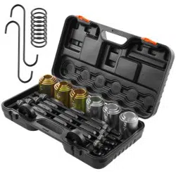
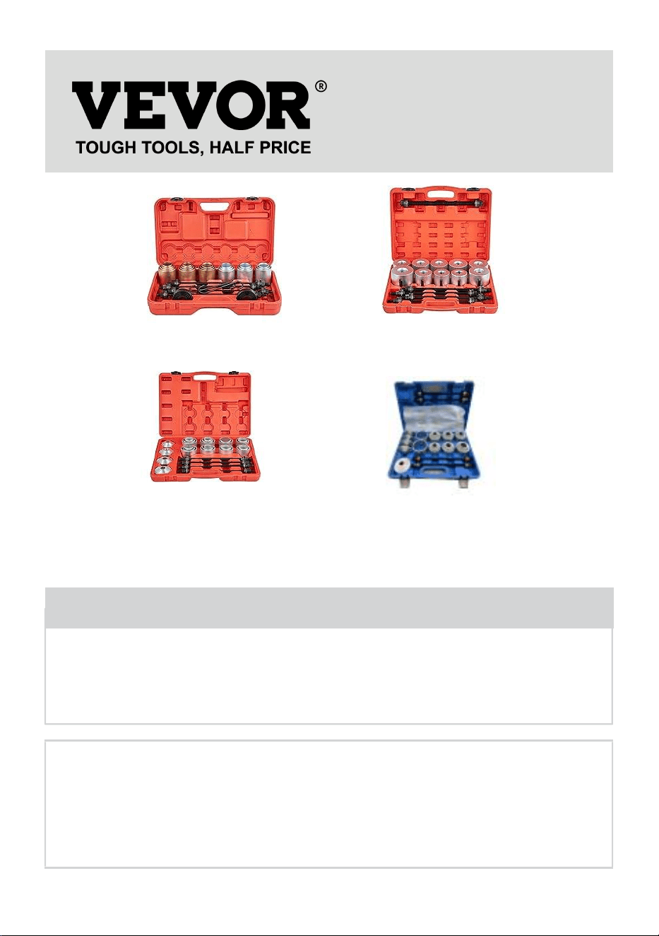
BUSHING EXTRACTOR
LX2001
27PCS
LX2002
26PCS
LX2003
28PCS
LX2004
36PCS

- 2 -
1. Important safety instructions
Warning - To reduce the risk of injury, user must read instructions
manual carefully.
Warning- Be sure to wear eye protectors when using this product.
Warning- Be sure to wear gloves when using this product.
2. Assembly precautions
1.Assemble only according to these instructions. Improper assembly can
create hazards.
2. Wear ANSI-approved safety goggles.
3.Keep the assembly area clean and well-lit.
4.Keep bystanders out of the area during assembly.
5.Do not assemble when tired or when under the influence of alcohol,
drugs, or medication.
6.Product capabilities apply to properly and completely assembled
products only.
Save this Instructions
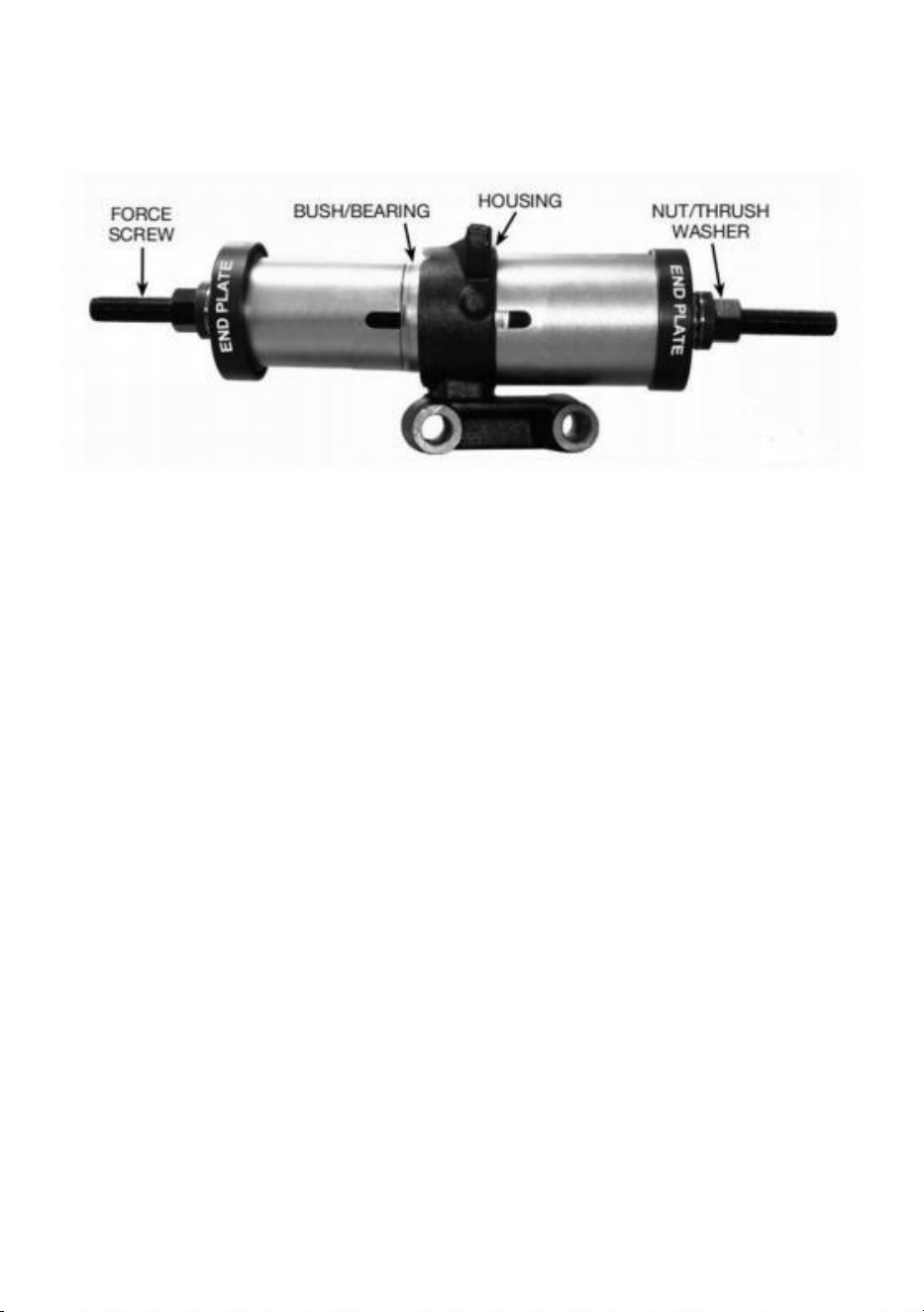
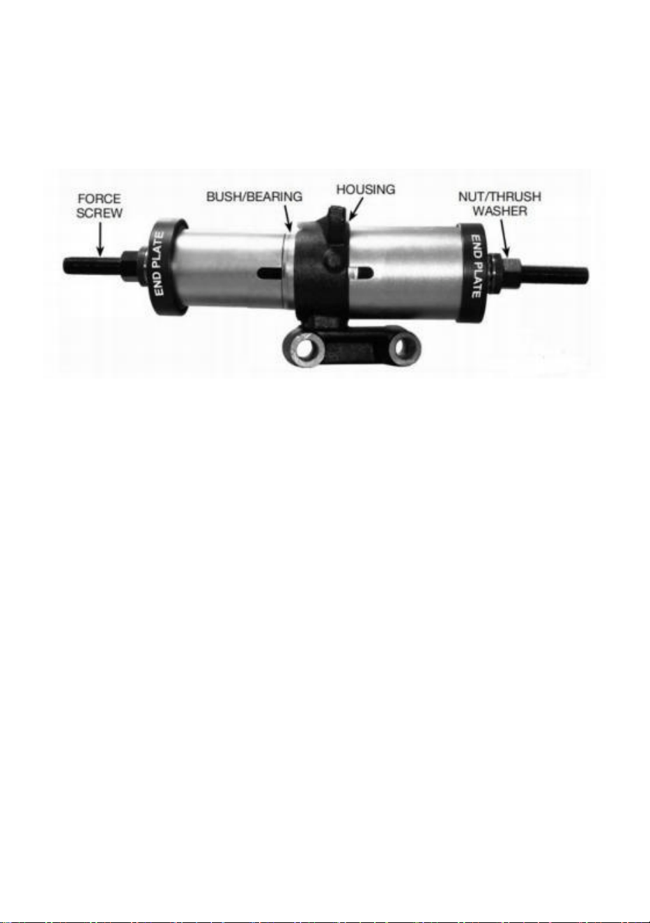
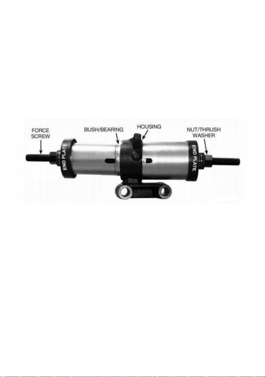
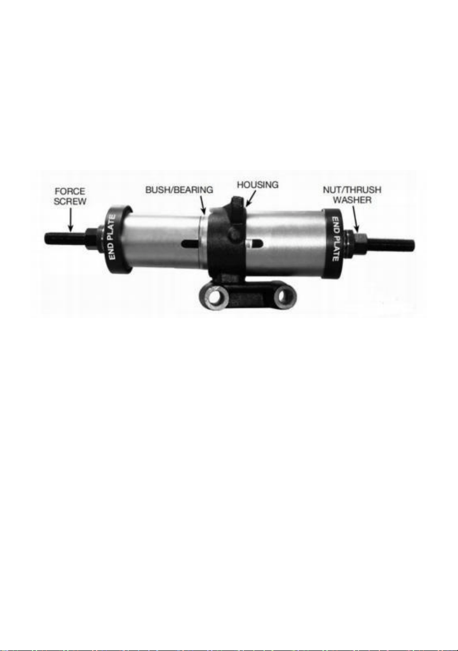
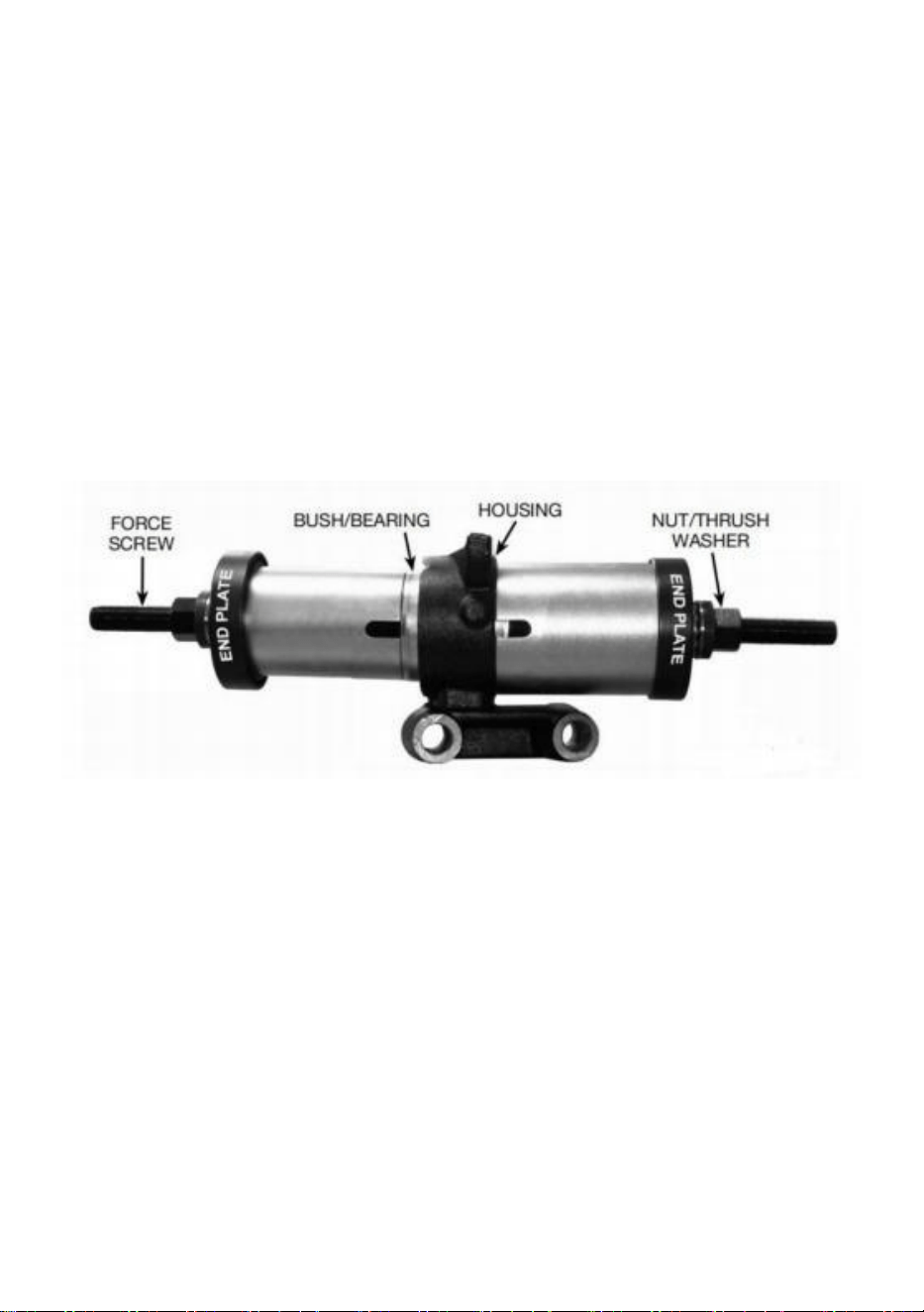
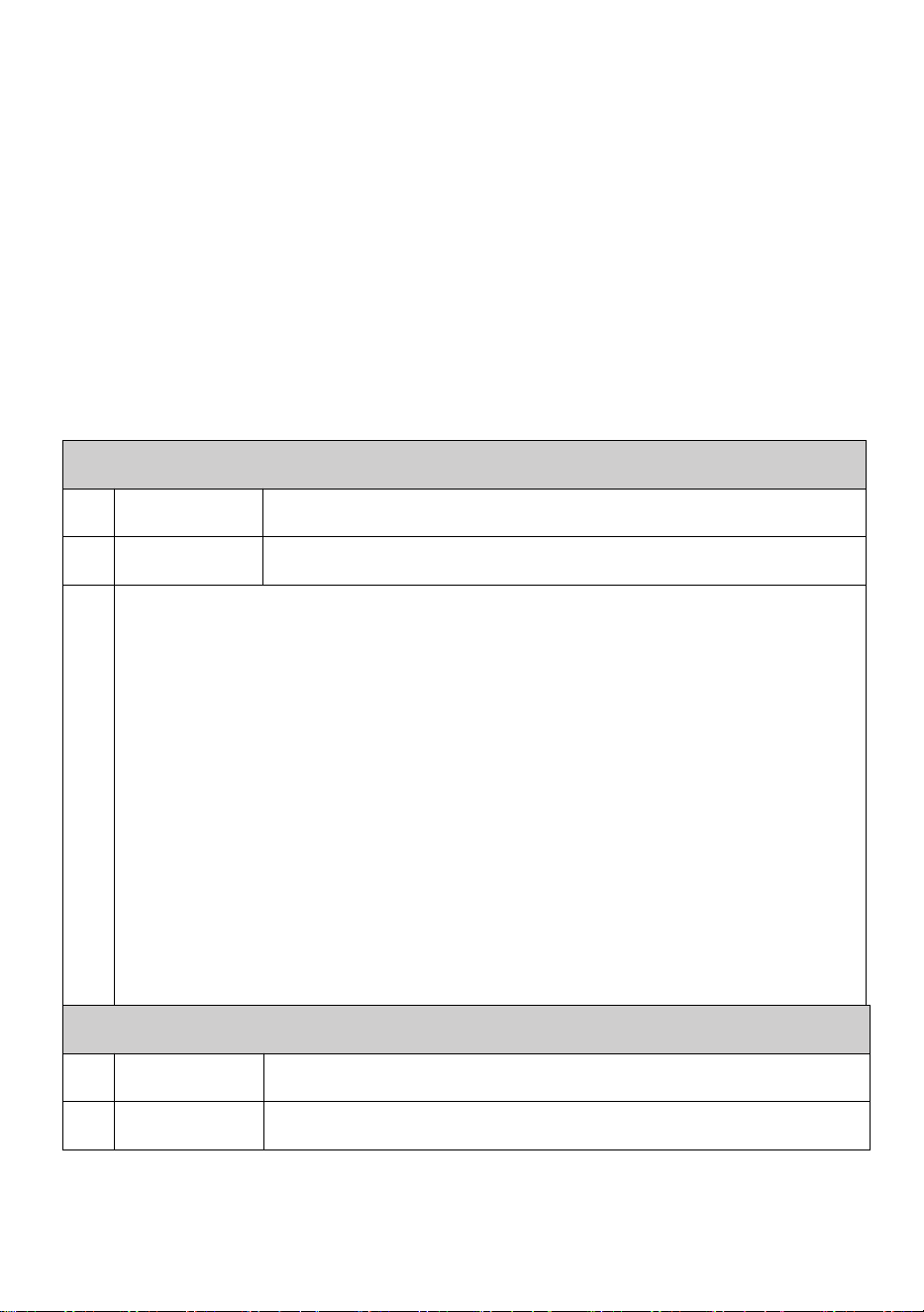
3. BUSHING/BEARING REMOVAL (Figure 1)

- 3 -
Figure 1
NOTE: Before starting, mark the place where the existing bushing is
installed to ensure accurate positioning of the replacement bushing.
3.1Select a sleeve that will sit square on the bushing/bearing housing and
will allow the bushing/bearing to be extracted without interference. Ensure
that only the force end of the sleeve with the U-shape inspection slot is
used to sit on the bushing/bearing housing. The stepped end of the sleeve
should be used to locate in the end plate.
3.2 elect a second sleeve that will sit square on the outer ring of the
bushing/bearing and will pass through the bushing/bearing housing without
interference. Ensure that only the force end of the sleeve with the U-shape
inspection slot is used to sit on the outer ring of the bushing/bearing. The
stepped end of the sleeve should be used to locate in the end plate.
3.3 Remove the nuts and thrust washers and pass the forcing screw halfway
through the bushing/bearing center hole.
NOTE: Lubricate the forcing screw before use.
NOTE: Always use the largest diameter forcing screw available that will
fit through the center of the bushing/bearing.
3.4 Fit the end plates to the stepped ends of the selected sleeves. Ensure
that side-A is only used for ‘A’ sleeves and side-B is only used for ‘ B’
sleeves.
3.5 Slide the assembled end plates and sleeves over the forcing screw and
install the thrust washers and nuts.
3.6Progressively tighten the nuts while locating the sleeves squarely on the
bushing/bearing housing and the bushing/bearing outer ring.
3.7 Once the sleeves are square on the housing and outer ring, tighten the
nuts and check that the thrust washers are centered in the end plates.
3.8 Using the appropriate sized wrenches hold the forcing nut that has the 3
pins and gradually tighten the forcing nut that has the bearing, driving
bushing/ bearing from the housing.
DO NOT use air tools to operate the force screw nuts.
DO NOT exceed the maximum recommended torque for each forcing
screw.
- 4 -
4. BUSHING/BEARING INSTALLATION (Figure 1)
Figure 1
4.1 Select the appropriate size sleeves for the housing and bushing/bearing
as described in the removal section.
4.2. Prior to installing the bushing/bearing, clean the inside of the housing
with an abrasive cloth to ensure that it is free of debris and corrosion.
4.3 Lightly oil the outer ring of the bushing/bearing to be installed.
4.4 You may use a hammer to gently tap around the outer ring of the
bushing/bearing to locate it into the housing.
NOTE: Make sure that the bushing/bearing is square to the housing
when installing.
NOTE: Always use the largest diameter forcing screw available that will
fit through the center of the bushing/bearing.
4.5 Lubricate the forcing screw.
4.6 Once the sleeves are square on the housing and outer ring, tighten the
nuts and check that the thrust washers are centered in the end plates.
4.7 Using the appropriate sized wrenches hold the forcing nut that has the 3
pins and gradually tighten the forc.
- 5 -
5. Product parameter
LX-2002 PARAMETER (26pcs)
1
Name
Bushing Extractor
2
Model
LX2002
3
Total QTY:26pcs,
Sleeve(20pcs): Material: 20#
D82/d72,D80/d70,D78/d68,D76/d66,D74/d64,D72/d62,D70/d60,
D68/d58,D66/d56,D64/d54,D62/d52,D60/d50,D58/d48,D56/d46,
D54/d44,D52/d42,D50/d40,D48/d38,D46/d36,D44/d34
Screw Rod(4pcs): Material: 40Cr. Hardness: 20-32HRC
M10mm,M12mm ,M14mm,M16mm .
Annulus(2pcs): Material: 45#; Φ83mm
Additional accessories: Break Hook*2pcs; O-ring *8pcs
LX-2001 PARAMETER (27pcs)
1
Name
Bushing Extractor
2
Model
LX2001
3
Total QTY:27pcs
Sleeve(22pcs): Material: 45#
D90/d80,D85/d75,D82/d72,D80/d70,D78/d68,D76/d66,D74/d64,
D72/d62,D70/d60,D68/d58,D66/d56,D64/d54,D62/d52,D60/d50,
D58/d48,D56/d46,D54/d44,D52/d42,D50/d40,D48/d38,D46/d36,
D44/d34
Screw Rod(5pcs): Material: 40Cr. Hardness: 20-32HRC
M10mm,M12mm,M14mm,M16mm,M18mm
Additional accessories: Break Hook*2pcs; O-ring *8pcs
- 6 -
LX-2003 PARAMETER (28pcs)
1
Name
Bushing Extractor
2
Model
LX2003
3
Total QTY:28pcs
Sleeve(20pcs): Material: 20#
D82/d72,D80/d70,D78/d68,D76/d66,D74/d64,D72/d62,D70/d60,
D68/d58,D66/d56,D64/d54,D62/d52,D60/d50,D58/d48,D56/d46,
D54/d44,D52/d42,D50/d40,D48/d38,D46/d36,D44/d34
Screw Rod(4pcs): Material: 40Cr. Hardness: 20-32HRC
M10mm,M12mm,M14mm,M16mm,
Annulus: Material(4pcs): 45#; Φ76mm*2pcs , Φ78mm*2pcs
Additional accessories: Break Hook*2pcs; O-ring *8pcs
LX-2004 PARAMETER (36pcs)
1
Name
Bushing Extractor
2
Model
LX2004
3
Total QTY:36pcs
Sleeve(27pcs): Material: 20#
D90/d80,D85/d75,D82/d72,D80/d70,D78/d68,D76/d66,D74/d64,
D72/d62,D70/d60,D68/d58,D66/d56,D64/d54,D62/d52,D60/d50,
D58/d48,D56/d46,D54/d44,D52/d42,D50/d40,D48/d38,D46/d36,
D44/d34,D42/d32,D40/d30,D38/d28,D36/d26,D34/d24
Screw Rod(4pcs): Material: 40Cr. Hardness: 20-32HRC
M10mm,M12mm,M14mm,M16mm,
Annulus(5pcs): Material: 45#; ⌀ 75、⌀ 77.5、⌀ 81、⌀ 85、⌀ 89
- 7 -
Manufacturer:Shanghaimuxinmuyeyouxiangongsi
Address: Shuangchenglu 803nong11hao1602A-1609shi, baoshanqu,
shanghai 200000 CN.
Imported to AUS: SIHAO PTY LTD. 1 ROKEVA STREETEASTWOOD
NSW 2122 Australia
Imported to USA: Sanven Technology Ltd. Suite 250, 9166 Anaheim
Place, Rancho Cucamonga, CA 91730


Teknisk Support och e-garanticertifikat www.vevor.com/support
BUSHING EXTRACTOR
PRODUKTMANUAL
We continue to be committed to provide you tools with competitive price.
"Save Half", "Half Price" or any other similar expressions used by us only represents an
estimate of savings you might benefit from buying certain tools with us compared to the major
top brands and does not necessarily mean to cover all categories of tools offered by us. You
are kindly reminded to verify carefully when you are placing an order with us if you are
actually saving half in comparison with the top major brands.


- 1 -
Have product questions? Need technical support? Please feel free to
contact us:
Technical Support and E-Warranty Certificate
www.vevor.com/support
NEED HELP? CONTACT US!
This is the original instruction, please read all manual instructions
carefully before operating. VEVOR reserves a clear interpretation of our
user manual. The appearance of the product shall be subject to the
product you received. Please forgive us that we won't inform you again if
there are any technology or software updates on our product.
BUSHING EXTRACTOR
LX2001
27PCS
LX2002
26PCS
LX2003
28PCS
LX2004
36PCS

- 2 -
3. Viktiga säkerhets instruktioner
Varning - För att minska risken för skada måste användaren läsa
bruksanvisningen noggrant.
Varning- Var noga med att bära ögonskydd när du använder
denna produkt.
Varning- Var noga med att bära handskar när du använder denna
produkt.
4. Försiktighetsåtgärder vid montering
1. Montera endast enligt dessa instruktioner. Felaktig montering kan skapa
faror.
2. Slitage ANSI-godkända skyddsglasögon .
3.Håll monteringsområdet rent och väl upplyst.
4. Håll åskådare borta från området under monteringen .
5. Montera inte när du är trött eller när under påverkan av alkohol, droger
eller mediciner.
6. Produktens kapacitet gäller korrekt och fullständigt monterade endast
produkter.
Spara dessa instruktioner
3 . BORTTAGNING AV BUSSNING/LAGER (Figur 1)

- 3 -
Figur 1
OBS: Innan du börjar, markera platsen där den befintliga bussningen är
installerad för att säkerställa korrekt placering av
ersättningsbussningen.
3.1Välj en hylsa som sitter rakt på bussningen/lagerhuset och gör att
bussningen/lagret kan dras ut utan störningar. Se till att endast kraftänden på
hylsan med den U-formade inspektionsspåret är
används för att sitta på bussningen/lagerhuset. Den stegade änden av hylsan
ska användas för att placeras i ändplattan.
3.2 välj en andra hylsa som kommer att sitta rakt på den yttre ringen av
bussning/lager och kommer att passera genom bussningen/lagerhuset utan
störningar. Se till att endast kraftänden på hylsan med U-formad
inspektionsspår används för att sitta på bussningens/lagrets yttre ring. Den
stegade änden av hylsan ska användas för att placeras i ändplattan.
3.3 Ta bort muttrarna och tryckbrickorna och för kraftskruven halvvägs
genom bussningens/lagrets mitthål.
OBS: Smörj pressskruven före användning.
OBS: Använd alltid den tvingande skruven med största diameter som
finns tillgänglig som passar genom bussningens/lagrets mitt.
3.4 Montera gavelplåtarna på de avtrappade ändarna av de valda hylsorna.
Se till att sida-A endast används för 'A'-ärmar och sida-B endast används för
'B'
ärmar.
3.5 Skjut de sammansatta ändplattorna och hylsorna över kraftskruven och
montera tryckbrickorna och muttrarna.
3.6 Dra åt muttrarna successivt samtidigt som hylsorna placeras rakt på
bussningen/lagerhuset och bussningens/lagrets yttre ring.
3.7 När hylsorna är fyrkantiga på huset och den yttre ringen, dra åt muttrarna
och kontrollera att tryckbrickorna är centrerade i ändplattorna.
3.8 Använd lämpliga skiftnycklar och håll i pressmuttern som har de 3 stiften
och dra gradvis åt pressmuttern som har lagret,
bussning/lager från huset.
ANVÄND INTE luftverktyg för att manövrera kraftskruvmuttrarna.
- 4 -
Överskrid INTE det maximala rekommenderade vridmomentet för varje
tvångsskruv.
4. INSTALLATION AV BUSSNING/LAGER (Figur 1)
Figur 1
4.1 Välj lämplig storlek på hylsor för hus och bussning/lager enligt
beskrivningen i demonteringsavsnittet.
4.2. Innan bussningen/lagret installeras, rengör insidan av huset med en
slipande trasa för att säkerställa att den är fri från skräp och korrosion.
4.3 Olja lätt in den yttre ringen på bussningen/lagret som ska installeras.
4.4 Du kan använda en hammare för att försiktigt knacka runt den yttre ringen
på bussningen/lagret för att lokalisera den i huset.
OBS: Se till att bussningen/lagret är vinkelrätt mot huset vid
installation.
OBS: Använd alltid den tvingande skruven med största diameter som
finns tillgänglig som passar genom bussningens/lagrets mitt.
4.5 Smörj pressskruven.
4.6 När hylsorna är fyrkantiga på huset och den yttre ringen, dra åt muttrarna
och kontrollera att tryckbrickorna är centrerade i ändplattorna.
4.7 Använd lämpliga skiftnycklar och håll i kraftmuttern som har de 3 stiften
och dra gradvis åt kraften.
- 5 -
6. Produktparameter
LX-2002 PARAMETER (26st)
1
namn
Bussning Extraktor
2
Modell
LX2002
3
Totalt antal : 26 st .
Sleeve ( 20st ) : Material: 20#
D82/d72,D80/d70,D78/d68,D76/d66,D74/d64,D72/d62,D70/d60,
D68/d58,D66/d56,D654/d54,D654/D50,D 8/ d48,D56/d46,D54/d44,
D52/d42,D50/d40,D48/d38,D46/d36,D44/d34
S besättningsstav (4 st) : Material: 40Cr. Hårdhet: 20-32HRC
M10mm , M12mm, M14 mm, M16mm .
A nnulus (2st) : Material: 45#; Φ 83 mm
Övriga tillbehör : Brytkrok*2st; O-ring *8st
LX-2001 PARAMETER (27st)
1
namn
Bussning Extraktor
2
Modell
LX2001
3
Totalt antal : 27st
Ärm ( 22st ) : Material: 45#
D90/d80,D85/d75,D82/d72,D80/d70,D78/d68,D76/d66,D74/d64,
D72/d62,D70/d60,D658/d66,D658/d56,D658/d56,D 2/ d52,D60/d50,
D58/d48,D56/d46,D54/d44,D52/d42,D50/d40,D48/d38,D46/d36,
D44/d34
S besättningsstång (5 st) : Material: 40Cr. Hårdhet: 20-32HRC
- 6 -
M10mm , M12mm , M14mm , M16mm ,M18mm
Övriga tillbehör : Brytkrok*2st; O-ring *8st
LX-2003 PARAMETER (28st)
1
namn
Bussning Extraktor
2
Modell
LX200 3
3
Totalt antal : 2 8st
Ärm ( 20st ) : Material: 20#
D82/d72,D80/d70,D78/d68,D76/d66,D74/d64,D72/d62,D70/d60,
D68/d58,D66/d56,D654/d54,D654/D50,D 8/ d48,D56/d46,D54/d44,
D52/d42,D50/d40,D48/d38,D46/d36,D44/d34
S besättningsstång (4 st) : Material: 40Cr. Hårdhet: 20-32HRC
M10mm , M12mm , M14mm , M16mm ,
A nnulus: Material(4st): 45#; Φ 76 mm *2st , Φ 78 mm *2st
Övriga tillbehör : Brytkrok*2st; O-ring *8st
LX-2004 PARAMETER (36st)
1
namn
Bussning Extraktor
2
Modell
LX200 4
3
Totalt antal : 36st
Ärm ( 27st ) : Material: 20#
D90/d80,D85/d75,D82/d72,D80/d70,D78/d68,D76/d66,D74/d64,
D72/d62,D70/d60,D658/d66,D658/d56,D658/d56,D 2/ d52,D60/d50,
D58/d48,D56/d46,D54/d44,D52/d42,D50/d40,D48/d38,D46/d36,
D44/d324/d40,D324/d30d 8, D36/d26, D34/d24
S besättningsstav (4 st) : Material: 40Cr. Hårdhet: 20-32HRC
M10mm , M12mm , M14mm , M16mm ,
- 7 -
A nnulus (5st) : Material: 45#; ⌀ 75,⌀ 77,5,⌀ 81,⌀ 85,⌀ 89
Tillverkare: Shanghaimuxinmuyeyouxiangongsi
Adress: Shuangchenglu 803nong11hao1602A-1609shi, baoshanqu,
shanghai 200000 CN.
Importerad till AUS: SIHAO PTY LTD. 1 ROKEVA STREETEASTWOOD
NSW 2122 Australien
Importerad till USA: Sanven Technology Ltd. Suite 250, 9166 Anaheim
Place, Rancho Cucamonga, CA 91730


Técnico Soporte y certificado de garantía electrónica www.vevor.com/support
EXTRACTOR DE BUJES
MANUAL DEL PRODUCTO
We continue to be committed to provide you tools with competitive price.
"Save Half", "Half Price" or any other similar expressions used by us only represents an
estimate of savings you might benefit from buying certain tools with us compared to the major
top brands and does not necessarily mean to cover all categories of tools offered by us. You
are kindly reminded to verify carefully when you are placing an order with us if you are
actually saving half in comparison with the top major brands.


- 1 -
Have product questions? Need technical support? Please feel free to
contact us:
Technical Support and E-Warranty Certificate
www.vevor.com/support
NEED HELP? CONTACT US!
This is the original instruction, please read all manual instructions
carefully before operating. VEVOR reserves a clear interpretation of our
user manual. The appearance of the product shall be subject to the
product you received. Please forgive us that we won't inform you again if
there are any technology or software updates on our product.
BUSHING EXTRACTOR
LX2001
27PCS
LX2002
26PCS
LX2003
28PCS
LX2004
36PCS

- 2 -
5. Instrucciones de seguridad importantes
Advertencia: para reducir el riesgo de lesiones, el usuario debe
leer atentamente el manual de instrucciones.
Advertencia: asegúrese de usar protectores para los ojos cuando
utilice este producto.
Advertencia: asegúrese de usar guantes cuando utilice este
producto.
6. Precauciones de montaje
1.Ensamble únicamente de acuerdo con estas instrucciones. Un montaje
inadecuado puede crear peligros.
2. usar Gafasde seguridad aprobadas por ANSI .
3. Mantenga el área de montaje limpia y bien iluminada.
4.Mantenga a otras personas fuera del área durante el montaje .
5. No montar cuando estés cansado o cuando bajo la influencia del alcohol,
drogas o medicamentos.
6. Las capacidades del producto se aplican de forma adecuada y
completa . ensamblado productos solamente.
Guarde estas instrucciones
3 . DESMONTAJE DEL BUJE/COJINETE (Figura 1)

- 3 -
Cifra 1
NOTA: Antes de comenzar, marque el lugar donde está instalado el
casquillo existente para garantizar la colocación precisa del casquillo
de reemplazo.
3.1Seleccione un manguito que quede cuadrado en la carcasa del
buje/cojinete y que permita extraer el buje/cojinete sin interferencias.
Asegúrese de que solo el extremo de fuerza del manguito con la ranura de
inspección en forma de U esté
solía sentarse en el casquillo/carcasa del cojinete. El extremo escalonado
del manguito debe usarse para ubicarlo en la placa final.
3.2 Elija una segunda manga que quede cuadrada en el anillo exterior del
casquillo/cojinete y pasará a través del casquillo/carcasa del cojinete sin
interferencias. Asegúrese de que solo se utilice el extremo de fuerza del
manguito con la ranura de inspección en forma de U para asentarse en el
anillo exterior del casquillo/cojinete. El extremo escalonado del manguito
debe usarse para ubicarlo en la placa terminal.
3.3 Retire las tuercas y las arandelas de empuje y pase el tornillo de fuerza
hasta la mitad del orificio central del buje/cojinete.
NOTA: Lubrique el tornillo de fuerza antes de usarlo.
NOTA: Utilice siempre el tornillo de fuerza de mayor diámetro disponible
que pase por el centro del buje/cojinete.
3.4 Coloque las placas finales en los extremos escalonados de las mangas
seleccionadas. Asegúrese de que el lado A solo se use para las mangas 'A' y
el lado B solo se use para las mangas 'B'
mangas.
3.5 Deslice las placas finales y los manguitos ensamblados sobre el tornillo
de presión e instale las arandelas y tuercas de empuje.
3.6 Apriete progresivamente las tuercas mientras ubica los manguitos
directamente en el casquillo/carcasa del cojinete y en el anillo exterior del
casquillo/cojinete.
3.7 Una vez que los manguitos estén cuadrados en la carcasa y el anillo
exterior, apriete las tuercas y verifique que las arandelas de empuje estén
centradas en las placas de los extremos.
- 4 -
3.8 Usando las llaves del tamaño adecuado, sostenga la tuerca de fuerza que
tiene los 3 pasadores y apriete gradualmente la tuerca de fuerza que tiene el
cojinete, impulsando
buje/cojinete de la carcasa.
NO utilice herramientas neumáticas para operar las tuercas de los
tornillos de fuerza.
NO exceda el torque máximo recomendado para cada tornillo de fuerza.
4. INSTALACIÓN DEL BUJE/COJINETE (Figura 1)
Cifra 1
4.1 Seleccione los manguitos del tamaño adecuado para la carcasa y el
casquillo/cojinete como se describe en la sección de extracción.
4.2. Antes de instalar el casquillo/cojinete, limpie el interior de la carcasa con
un paño abrasivo para asegurarse de que esté libre de residuos y corrosión.
4.3 Engrase ligeramente el anillo exterior del casquillo/cojinete a instalar.
4.4 Puede usar un martillo para golpear suavemente alrededor del anillo
exterior del casquillo/cojinete para ubicarlo en la carcasa.
NOTA: Asegúrese de que el casquillo/cojinete esté en escuadra con la
carcasa durante la instalación.
NOTA: Utilice siempre el tornillo de fuerza de mayor diámetro disponible
que pase por el centro del buje/cojinete.
4.5 Lubricar el tornillo de fuerza.
4.6 Una vez que los manguitos estén cuadrados en la carcasa y el anillo
exterior, apriete las tuercas y verifique que las arandelas de empuje estén
- 5 -
centradas en las placas de los extremos.
4.7 Usando llaves del tamaño adecuado, sostenga la tuerca de fuerza que
tiene los 3 pasadores y apriete gradualmente la fuerza.
7. Parámetro del producto
LX-2002 PARÁMETRO (26 piezas)
1
Nombre
Cojinete Extractor
2
Modelo
LX2002
3
Cantidad total : 26 unidades .
Manga (20 piezas) : Material : 20#
D82/d72,D80/d70,D78/d68,D76/d66,D74/d64,D72/d62,D70/d60,D68/d58
,D66/d56,D64/d54,D62/d52,D60/d50,D58/
d48,D56/d46,D54/d44,D52/d42,D50/d40,D48/d38,D46/d36,D44/d34
de tripulación S (4 piezas) : Material: 40Cr. Dureza: 20-32HRC
M10mm , M12mm, M14mm, M16mm .
Anillo (2 piezas) : Material : 45#; Φ 83 mm
Accesorios adicionales : Gancho de rotura * 2 piezas; Junta tórica *8
piezas
PARÁMETRO LX-2001 (27 piezas)
1
Nombre
Cojinete Extractor
2
Modelo
LX2001
- 6 -
3
Cantidad total : 27piezas
Manga (22 piezas ) : Materiales: 45#
D90/d80,D85/d75,D82/d72,D80/d70,D78/d68,D76/d66,D74/d64,D72/d62,
D70/d60,D68/d58,D66/d56,D64/d54,D62/
d52,D60/d50,D58/d48,D56/d46,D54/d44,D52/d42,D50/d40,D48/d38,D46/d
36,D44/d34
de tripulación S (5 piezas) : Material: 40Cr. Dureza: 20-32HRC
M10 mm , M12 mm , M14 mm , M16 mm , M18 mm
Accesorios adicionales : Gancho de rotura * 2 piezas; Junta tórica *8
piezas
PARÁMETRO LX-2003 (28 piezas)
1
Nombre
Cojinete Extractor
2
Modelo
LX200 3
3
Cantidad total : 2 8piezas
Manga (20 piezas ) : Materiales: 20#
D82/d72,D80/d70,D78/d68,D76/d66,D74/d64,D72/d62,D70/d60,D68/d58,
D66/d56,D64/d54,D62/d52,D60/d50,D58/
d48,D56/d46,D54/d44,D52/d42,D50/d40,D48/d38,D46/d36,D44/d34
de tripulación S (4 piezas) : Material: 40Cr. Dureza: 20-32HRC
M10 mm , M12 mm , M14 mm , M16 mm ,
Ánulo : Material (4 piezas): 45#; Φ 76 mm * 2 piezas , Φ 78 mm * 2
piezas
Accesorios adicionales : Gancho de rotura * 2 piezas; Junta tórica *8
piezas
PARÁMETRO LX-2004 (36 piezas)
1
Nombre
Cojinete Extractor
- 7 -
2
Modelo
LX200 4
3
Cantidad total : 36piezas
Manga (27 piezas ) : Materiales: 20#
D90/d80,D85/d75,D82/d72,D80/d70,D78/d68,D76/d66,D74/d64,D72/d62,
D70/d60,D68/d58,D66/d56,D64/d54,D62/
d52,D60/d50,D58/d48,D56/d46,D54/d44,D52/d42,D50/d40,D48/d38,D46/d
36,D44/d34,D42/d32,D40/d30,D38/d28, D36/d26,D34/d24
de tripulación S (4 piezas) : Material: 40Cr. Dureza: 20-32HRC
M10 mm , M12 mm , M14 mm , M16 mm ,
Anillo (5 piezas) : Material : 45#; ⌀ 75、⌀ 77.5、⌀ 81、⌀ 85、⌀ 89
Fabricante: Shanghaimuxinmuyeyouxiangongsi
Dirección: Shuangchenglu 803nong11hao1602A-1609shi, baoshanqu,
shanghai 200000 CN.
Importado a AUS: SIHAO PTY LTD. 1 ROKEVA STREET ASTWOOD
NSW 2122 Australia
Importado a EE. UU.: Sanven Technology Ltd. Suite 250, 9166 Anaheim
Lugar, Rancho Cucamonga, CA 91730


Tecnico Supporto e certificato di garanzia elettronica www.vevor.com/support
ESTRATTORE BOCCOLA
MANUALE DEL PRODOTTO
We continue to be committed to provide you tools with competitive price.
"Save Half", "Half Price" or any other similar expressions used by us only represents an
estimate of savings you might benefit from buying certain tools with us compared to the major
top brands and does not necessarily mean to cover all categories of tools offered by us. You
are kindly reminded to verify carefully when you are placing an order with us if you are
actually saving half in comparison with the top major brands.


- 1 -
Have product questions? Need technical support? Please feel free to
contact us:
Technical Support and E-Warranty Certificate
www.vevor.com/support
NEED HELP? CONTACT US!
This is the original instruction, please read all manual instructions
carefully before operating. VEVOR reserves a clear interpretation of our
user manual. The appearance of the product shall be subject to the
product you received. Please forgive us that we won't inform you again if
there are any technology or software updates on our product.
BUSHING EXTRACTOR
LX2001
27PCS
LX2002
26PCS
LX2003
28PCS
LX2004
36PCS

- 2 -
7. Importanti istruzioni di sicurezza
Avvertenza - Per ridurre il rischio di lesioni, l'utente deve leggere
attentamente il manuale di istruzioni.
Avvertenza: assicurarsi di indossare protezioni per gli occhi
quando si utilizza questo prodotto.
Avvertenza: assicurarsi di indossare guanti quando si utilizza
questo prodotto.
8. Precauzioni per il montaggio
1.Montare solo seguendo queste istruzioni. Un assemblaggio improprio
può creare pericoli.
2. Indossare Occhialidi sicurezza approvati ANSI .
3.Mantenere l'area di assemblaggio pulita e ben illuminata.
4.Tenere gli astanti lontani dall'area durante il montaggio .
5.Non montare quando sei stanco o quando sotto l'influenza dell'alcol,
farmaci o medicinali.
6. Le capacità del prodotto si applicano correttamente e completamente
assemblato solo prodotti.
Salva queste istruzioni
3 . RIMOZIONE BOCCOLA/CUSCINETTO (Figura 1)

- 3 -
Figura 1
NOTA: prima di iniziare, segnare il punto in cui è installata la boccola
esistente per garantire il posizionamento accurato della boccola
sostitutiva.
3.1Selezionare un manicotto che sia posizionato perpendicolarmente
sull'alloggiamento della boccola/cuscinetto e consenta l'estrazione della
boccola/cuscinetto senza interferenze. Assicurarsi che sia presente solo
l'estremità di forza del manicotto con la fessura di ispezione a forma di U
utilizzato per sedersi sull'alloggiamento della boccola/cuscinetto. L'estremità
a gradini del manicotto deve essere utilizzata per posizionarla nella piastra
terminale.
3.2 eleggere un secondo manicotto che si posizionerà quadrato sull'anello
esterno del
boccola/cuscinetto e passerà attraverso l'alloggiamento della
boccola/cuscinetto senza interferenze. Assicurarsi che solo l'estremità di
forza del manicotto con la fessura di ispezione a forma di U venga utilizzata
per posizionarsi sull'anello esterno della boccola/cuscinetto. L'estremità a
gradini del manicotto deve essere utilizzata per posizionarla nella piastra
terminale.
3.3 Rimuovere i dadi e le rondelle reggispinta e far passare la vite di
forzatura a metà del foro centrale della boccola/cuscinetto.
NOTA: Lubrificare la vite di forzatura prima dell'uso.
NOTA: utilizzare sempre la vite di forzatura dal diametro più grande
disponibile che possa passare attraverso il centro della
boccola/cuscinetto.
3.4 Montare le piastre terminali sulle estremità a gradini dei manicotti
selezionati. Assicurarsi che il lato A sia utilizzato solo per le maniche "A" e
che il lato B sia utilizzato solo per le maniche "B"
maniche.
3.5 Far scorrere le piastre terminali e i manicotti assemblati sulla vite di
forzamento e installare le rondelle reggispinta e i dadi.
3.6 Stringere progressivamente i dadi posizionando i manicotti esattamente
sull'alloggiamento della boccola/cuscinetto e sull'anello esterno della

- 4 -
boccola/cuscinetto.
3.7 Una volta che le bussole sono squadrate sull'alloggiamento e sull'anello
esterno, serrare i dadi e verificare che le rondelle reggispinta siano centrate
nelle piastre terminali.
3.8 Utilizzando le chiavi di dimensioni adeguate, tenere fermo il dado di
forzatura che contiene i 3 perni e serrare gradualmente il dado di forzatura
che contiene il cuscinetto, guidando
boccola/cuscinetto dall'alloggiamento.
NON utilizzare strumenti pneumatici per azionare i dadi delle viti di
forza.
NON superare la coppia massima consigliata per ciascuna vite di
forzatura.
4. INSTALLAZIONE BOCCOLA/CUSCINETTO (Figura 1)
Figura 1
4.1 Selezionare i manicotti di dimensioni adeguate per l'alloggiamento e la
boccola/cuscinetto come descritto nella sezione relativa alla rimozione.
4.2. Prima di installare la boccola/cuscinetto, pulire l'interno
dell'alloggiamento con un panno abrasivo per assicurarsi che sia privo di
detriti e corrosione.
4.3 Oliare leggermente l'anello esterno della boccola/cuscinetto da installare.
4.4 È possibile utilizzare un martello per battere delicatamente attorno
all'anello esterno della boccola/cuscinetto per posizionarlo
nell'alloggiamento.
- 5 -
NOTA: assicurarsi che la boccola/cuscinetto sia perpendicolare
all'alloggiamento durante l'installazione.
NOTA: utilizzare sempre la vite di forzatura dal diametro più grande
disponibile che possa passare attraverso il centro della
boccola/cuscinetto.
4.5 Lubrificare la vite di forzamento.
4.6 Una volta che le bussole sono squadrate sull'alloggiamento e sull'anello
esterno, serrare i dadi e verificare che le rondelle reggispinta siano centrate
nelle piastre terminali.
4.7 Utilizzando le chiavi di dimensioni adeguate, tenere fermo il dado di
forzatura dotato di 3 perni e serrare gradualmente la forza.
8. Parametro del prodotto
LX-2002 PARAMETRO (26 pezzi)
1
Nome
Boccola Estrattore
2
Modello
LX2002
3
Qtà totale : 26 pezzi ,
Manica a S (20 pezzi) : Materiale: 20#
D82/d72, D80/d70, D78/d68, D76/d66, D74/d64, D72/d62, D70/d60,
D68/d58, D66/d56, D64/d54, D62/d52, D60/d50, D58/ d48, D56/d46,
D54/d44, D52/d42, D50/d40, D48/d38, D46/d36, D44/d34
dell'equipaggio S (4 pezzi) : Materiale: 40Cr. Durezza: 20-32HRC
M10mm , M12mm, M14mm, M16mm .
Anello (2 pezzi) : Materiale : 45#; Φ 83 mm
Accessori aggiuntivi : Gancio spezzato*2 pezzi; O-ring *8 pezzi
- 6 -
PARAMETRO LX-2001 (27 pezzi)
1
Nome
Boccola Estrattore
2
Modello
LX2001
3
Quantità totale : 27pz
Manica a S (22 pezzi) : Materiale: 45#
D90/d80, D85/d75, D82/d72, D80/d70, D78/d68, D76/d66, D74/d64,
D72/d62, D70/d60, D68/d58, D66/d56, D64/d54, D62/ d52, D60/d50,
D58/d48, D56/d46, D54/d44, D52/d42, D50/d40, D48/d38, D46/d36,
D44/d34
dell'equipaggio S (5 pezzi) : Materiale: 40Cr. Durezza: 20-32HRC
M10mm , M12mm , M14mm , M16mm , M18mm
Accessori aggiuntivi : Gancio spezzato*2 pezzi; O-ring *8 pezzi
PARAMETRO LX-2003 (28 pezzi)
1
Nome
Boccola Estrattore
2
Modello
LX2003
3
Qtà totale : 2 8pz
Manica a S (20 pezzi) : Materiale: 20#
D82/d72, D80/d70, D78/d68, D76/d66, D74/d64, D72/d62, D70/d60,
D68/d58, D66/d56, D64/d54, D62/d52, D60/d50, D58/ d48, D56/d46,
D54/d44, D52/d42, D50/d40, D48/d38, D46/d36, D44/d34
dell'equipaggio S (4 pezzi) : Materiale: 40Cr. Durezza: 20-32HRC
M10mm , M12mm , M14mm , M16mm ,
Anello : Materiale (4 pezzi): 45#; Φ 76 mm *2 pezzi, Φ 78 mm *2 pezzi
Accessori aggiuntivi : Gancio spezzato*2 pezzi; O-ring *8 pezzi
PARAMETRO LX-2004 (36 pezzi)
1
Nome
Boccola Estrattore
- 7 -
2
Modello
LX2004
3
Quantità totale : 36pz
Manica a S (27 pezzi) : Materiale: 20#
D90/d80, D85/d75, D82/d72, D80/d70, D78/d68, D76/d66, D74/d64,
D72/d62, D70/d60, D68/d58, D66/d56, D64/d54, D62/ d52, D60/d50,
D58/d48, D56/d46, D54/d44, D52/d42, D50/d40, D48/d38, D46/d36,
D44/d34, D42/d32, D40/d30, D38/d28, D36/d26, D34/d24
dell'equipaggio S (4 pezzi) : Materiale: 40Cr. Durezza: 20-32HRC
M10mm , M12mm , M14mm , M16mm ,
Anello (5 pezzi) : Materiale : 45#; ⌀ 75、⌀ 77.5、⌀ 81、⌀ 85、⌀ 89
Produttore: Shanghaimuxinmuyeyouxiangongsi
Indirizzo: Shuangchenglu 803nong11hao1602A-1609shi, baoshanqu,
shanghai 200000 CN.
Importato in AUS: SIHAO PTY LTD. 1 ROKEVA STREETEASTWOOD
NSW 2122 Australia
Importato negli Stati Uniti: Sanven Technology Ltd. Suite 250, 9166
Anaheim
Luogo, Rancho Cucamonga, CA 91730


Techniczny Certyfikat wsparcia i e-gwarancji www.vevor.com/support
WYCIĄGACZ TULEI
INSTRUKCJA OBSŁUGI
We continue to be committed to provide you tools with competitive price.
"Save Half", "Half Price" or any other similar expressions used by us only represents an
estimate of savings you might benefit from buying certain tools with us compared to the major
top brands and does not necessarily mean to cover all categories of tools offered by us. You
are kindly reminded to verify carefully when you are placing an order with us if you are
actually saving half in comparison with the top major brands.


- 1 -
Have product questions? Need technical support? Please feel free to
contact us:
Technical Support and E-Warranty Certificate
www.vevor.com/support
NEED HELP? CONTACT US!
This is the original instruction, please read all manual instructions
carefully before operating. VEVOR reserves a clear interpretation of our
user manual. The appearance of the product shall be subject to the
product you received. Please forgive us that we won't inform you again if
there are any technology or software updates on our product.
BUSHING EXTRACTOR
LX2001
27PCS
LX2002
26PCS
LX2003
28PCS
LX2004
36PCS

- 2 -
9. Ważne instrukcje dotyczące bezpieczeństwa
Ostrzeżenie — aby zmniejszyć ryzyko obrażeń, użytkownik musi
uważnie przeczytać instrukcję obsługi.
Ostrzeżenie — podczas korzystania z tego produktu należy nosić
okulary ochronne.
Ostrzeżenie — podczas korzystania z tego produktu należy nosić
rękawiczki.
10. Środki ostrożności przy montażu
1.Montaż wyłącznie według niniejszej instrukcji. Nieprawidłowy montaż
może tworzyć zagrożenia.
2. Noś Okularyochronne zatwierdzone przez ANSI .
3. Utrzymuj miejsce montażu w czystości i dobrze oświetlone.
4. Podczas montażu nie dopuszczaj osób postronnych do obszaru .
5. Nie montuj, gdy jesteś zmęczony lub kiedy pod wpływem alkoholu,
narkotyki, czy lekarstwa.
6. Możliwości produktu dotyczą prawidłowo i całkowicie zmontowane tylko
produkty.
Zapisz tę instrukcję
3 . DEMONTAŻ TULEI/ŁOŻYSKA (Rysunek 1)

- 3 -
Postać 1
UWAGA: Przed rozpoczęciem należy zaznaczyć miejsce montażu
istniejącej tulei, aby zapewnić dokładne umiejscowienie tulei zamiennej.
3.1 Wybierz tuleję, która będzie osadzona prosto na tulei/obudowie łożyska i
umożliwi wyciągnięcie tulei/łożyska bez zakłóceń. Upewnij się, że tylko
koniec tulei ze szczeliną inspekcyjną w kształcie litery U jest zamontowany
używany do osadzenia na tulei/obudowie łożyska. Do umieszczenia w płycie
końcowej należy wykorzystać schodkowy koniec tulei.
3.2 wybierz drugą tuleję, która będzie osadzona prosto na zewnętrznym
pierścieniu
tulei/łożyska i przejdzie przez tuleję/obudowę łożyska bez zakłóceń. Upewnij
się, że tylko koniec tulei z otworem kontrolnym w kształcie litery U jest
osadzony na zewnętrznym pierścieniu tulei/łożyska. Do umieszczenia w
płycie końcowej należy wykorzystać schodkowy koniec tulei.
3.3 Zdejmij nakrętki i podkładki oporowe i przełóż śrubę dociskową do połowy
przez środkowy otwór tulei/łożyska.
UWAGA: Przed użyciem nasmaruj śrubę dociskową.
UWAGA: Zawsze używaj śruby dociskowej o największej dostępnej
średnicy, która zmieści się przez środek tulei/łożyska.
3.4 Dopasuj blachy końcowe do schodkowych końców wybranych tulei.
Upewnij się, że strona A jest używana tylko dla rękawów „A”, a strona B jest
używana tylko dla „B”
rękawy.
3.5 Nasunąć zmontowane płyty końcowe i tuleje na śrubę dociskową i
zamontować podkładki oporowe oraz nakrętki.
3.6 Stopniowo dokręcaj nakrętki, umieszczając tuleje prosto na
tulei/obudowie łożyska i na pierścieniu zewnętrznym tulei/łożyska.
3.7 Po ustawieniu tulei na oprawie i pierścieniu zewnętrznym dokręcić
nakrętki i sprawdzić, czy podkładki oporowe są wycentrowane w płytach
końcowych.
3.8 Za pomocą kluczy o odpowiedniej wielkości przytrzymaj nakrętkę
dociskową z 3 kołkami i stopniowo dokręcaj nakrętkę dociskową z łożyskiem,
wkręcając
- 4 -
tuleja/łożysko z obudowy.
NIE WOLNO używać narzędzi pneumatycznych do obsługi nakrętek śrub
siłowych.
NIE przekraczać maksymalnego zalecanego momentu obrotowego dla
każdej śruby dociskowej.
4. MONTAŻ TULEI/ŁOŻYSKA (Rysunek 1)
Postać 1
4.1 Wybierz tuleje o odpowiednim rozmiarze dla oprawy i tulei/łożyska, jak
opisano w części dotyczącej demontażu.
4.2. Przed montażem tulei/łożyska należy oczyścić wnętrze obudowy
ściereczką ścierną, aby upewnić się, że jest wolne od zanieczyszczeń i
korozji.
4.3 Lekko nasmaruj pierścień zewnętrzny montowanej tulei/łożyska.
4.4 Można delikatnie uderzać młotkiem wokół zewnętrznego pierścienia
tulei/łożyska, aby umieścić go w obudowie.
UWAGA: Podczas montażu upewnij się, że tuleja/łożysko jest ustawione
prostopadle do obudowy.
UWAGA: Zawsze używaj śruby dociskowej o największej dostępnej
średnicy, która zmieści się przez środek tulei/łożyska.
4.5 Nasmarować śrubę dociskową.
4.6 Po ustawieniu tulei na oprawie i pierścieniu zewnętrznym dokręcić
nakrętki i sprawdzić, czy podkładki oporowe są wycentrowane w płytach
końcowych.
- 5 -
4.7 Używając kluczy o odpowiedniej wielkości, przytrzymaj nakrętkę
dociskową z 3 kołkami i stopniowo zwiększaj siłę.
9. Parametr produktu
LX-2002 PARAMETR (26szt)
1
Nazwa
Tuleja Ekstraktor
2
Model
LX2002
3
Całkowita ilość : 26 sztuk ,
Rękaw (20szt) : Materiał : 20#
D82/d72, D80/d70, D78/d68, D76/d66, D74/d64, D72/d62, D70/d60,
D68/d58, D66/d56, D64/d54, D62/d52, D60/d50, D5 8/ d48, D56/d46,
D54/d44, D52/d42, D50/d40, D48/d38, D46/d36, D44/d34
załogi S (4 sztuki) : Materiał: 40Cr. Twardość: 20-32HRC
M10mm , M12mm, M14mm, M16mm .
Pierścień (2 szt.) : Materiał : 45 #; Φ 83 mm
Dodatkowe akcesoria : Hak zrywający * 2 szt.; O-ring *8szt
PARAMETR LX-2001 (27 szt.)
1
Nazwa
Tuleja Ekstraktor
2
Model
LX2001
Całkowita ilość : 27szt
Rękaw (22 szt. ) : Materiał: 45 #
D90/d80, D85/d75, D82/d72, D80/d70, D78/d68, D76/d66, D74/d64,
- 6 -
3
D72/d62, D70/d60, D68/d58, D66/d56, D64/d54, D6 2/ d52, D60/d50,
D58/d48, D56/d46, D54/d44, D52/d42, D50/d40, D48/d38, D46/d36,
D44/d34
załogi S (5 sztuk) : Materiał: 40Cr. Twardość: 20-32HRC
M10mm , M12mm , M14mm , M16mm , M18mm
Dodatkowe akcesoria : Hak zrywający * 2 szt.; O-ring *8szt
PARAMETR LX-2003 (28 szt.)
1
Nazwa
Tuleja Ekstraktor
2
Model
LX200 3
3
Całkowita ilość : 2 8szt
Rękaw ( 20szt ) : Materiał: 20 #
D82/d72, D80/d70, D78/d68, D76/d66, D74/d64, D72/d62, D70/d60,
D68/d58, D66/d56, D64/d54, D62/d52, D60/d50, D5 8/ d48, D56/d46,
D54/d44, D52/d42, D50/d40, D48/d38, D46/d36, D44/d34
załogi S (4 sztuki) : Materiał: 40Cr. Twardość: 20-32HRC
M10mm , M12mm , M14mm , M16mm ,
Pierścień : Materiał (4 sztuki): 45 #; Φ 76 mm *2 szt., Φ 78 mm *2 szt
Dodatkowe akcesoria : Hak zrywający * 2 szt.; O-ring *8szt
PARAMETR LX-2004 (36 szt.)
1
Nazwa
Tuleja Ekstraktor
2
Model
LX200 4
Całkowita ilość : 36szt
Rękaw ( 27szt ) : Materiał: 20 #
D90/d80, D85/d75, D82/d72, D80/d70, D78/d68, D76/d66, D74/d64,
D72/d62, D70/d60, D68/d58, D66/d56, D64/d54, D6 2/ d52, D60/d50,
D58/d48, D56/d46, D54/d44, D52/d42, D50/d40, D48/d38, D46/d36,
- 7 -
3
D44/d34, D42/d32, D40/d30, D38/d2 8, D36/d26, D34/d24
załogi S (4 sztuki) : Materiał: 40Cr. Twardość: 20-32HRC
M10mm , M12mm , M14mm , M16mm ,
Pierścień (5 sztuk) : Materiał : 45 #; ⌀ 75, ⌀ 77,5, ⌀ 81, ⌀ 85, ⌀ 89
Producent: Shanghaimuxinmuyeyouxiangongsi
Adres: Shuangchenglu 803nong11hao1602A-1609shi, baoshanqu,
szanghaj 200000 CN.
Import do AUS: SIHAO PTY LTD. 1 ROKEVA STREETEASTWOOD NSW
2122 Australia
Import do USA: Sanven Technology Ltd. Suite 250, 9166 Anaheim
Place, Rancho Cucamonga, Kalifornia 91730


Technisch Support und E-Garantie-Zertifikat www.vevor.com/support
BUCHSENABZIEHER
BEDIENUNGSANLEITUNG
We continue to be committed to provide you tools with competitive price.
"Save Half", "Half Price" or any other similar expressions used by us only represents an
estimate of savings you might benefit from buying certain tools with us compared to the major
top brands and does not necessarily mean to cover all categories of tools offered by us. You
are kindly reminded to verify carefully when you are placing an order with us if you are
actually saving half in comparison with the top major brands.


- 1 -
Have product questions? Need technical support? Please feel free to
contact us:
Technical Support and E-Warranty Certificate
www.vevor.com/support
NEED HELP? CONTACT US!
This is the original instruction, please read all manual instructions
carefully before operating. VEVOR reserves a clear interpretation of our
user manual. The appearance of the product shall be subject to the
product you received. Please forgive us that we won't inform you again if
there are any technology or software updates on our product.
BUSHING EXTRACTOR
LX2001
27PCS
LX2002
26PCS
LX2003
28PCS
LX2004
36PCS

- 2 -
11. Wichtige Sicherheitsanweisungen
Warnung – Um das Verletzungsrisiko zu verringern, muss der
Benutzer die Bedienungsanleitung sorgfältig lesen.
Warnung: Tragen Sie bei der Verwendung dieses Produkts
unbedingt einen Augenschutz.
Achtung: Tragen Sie bei der Verwendung dieses Produkts
unbedingt Handschuhe.
12. Vorsichtsmaßnahmen bei der Montage
1. Nur gemäß dieser Anleitung zusammenbauen. Eine unsachgemäße
Montage kann erstellen Gefahren.
2. Tragen ANSI-geprüfte Schutzbrille.
3. Halten Sie den Versammlungsbereich sauber und gut beleuchtet.
4. Halten Sie während der Montage unbeteiligte Personen vom Bereich
fern .
5. Nicht zusammenbauen, wenn Sie müde sind oder unter Alkoholeinfluss,
Drogen oder Medikamente.
6.Produktfunktionen gelten für richtig und vollständig gebaut Nur Produkte.
Bewahren Sie diese Anleitung auf
3. AUSBAU DER BUCHSE/LAGER (Abbildung 1)

- 3 -
Figur 1
HINWEIS: Markieren Sie vor dem Start die Stelle, an der die vorhandene
Buchse installiert ist, um eine genaue Positionierung der Ersatzbuchse
sicherzustellen.
3.1Wählen Sie eine Hülse, die rechtwinklig auf dem Buchsen-/Lagergehäuse
sitzt und ein ungehindertes Herausziehen der Buchse/des Lagers ermöglicht.
Stellen Sie sicher, dass nur das Kraftende der Hülse mit dem U-förmigen
Inspektionsschlitz
Wird verwendet, um auf der Buchse/dem Lagergehäuse zu sitzen. Das
abgestufte Ende der Hülse sollte verwendet werden, um in der Endplatte zu
positionieren.
3.2 Wählen Sie eine zweite Hülse, die rechtwinklig auf dem Außenring des
Buchse/Lager und passt ohne Behinderung durch das
Buchsen-/Lagergehäuse. Stellen Sie sicher, dass nur das Kraftende der
Hülse mit dem U-förmigen Inspektionsschlitz verwendet wird, um auf dem
Außenring der Buchse/des Lagers zu sitzen. Das abgestufte Ende der Hülse
sollte verwendet werden, um in der Endplatte zu positionieren.
3.3 Entfernen Sie die Muttern und Anlaufscheiben und führen Sie die
Druckschraube zur Hälfte durch das Mittelloch der Buchse/des Lagers.
HINWEIS: Die Abdrückschraube vor dem Gebrauch schmieren.
HINWEIS: Verwenden Sie stets die Druckschraube mit dem größten
verfügbaren Durchmesser, die durch die Mitte der Buchse/des Lagers
passt.
3.4 Passen Sie die Endplatten an die abgestuften Enden der ausgewählten
Hülsen an. Stellen Sie sicher, dass Seite A nur für Hülsen der Größe A und
Seite B nur für Hülsen der Größe B verwendet wird.
Ärmel.
3.5 Die montierten Endplatten und Hülsen über die Abdrückschraube
schieben und die Anlaufscheiben und Muttern montieren.
3.6 Ziehen Sie die Muttern schrittweise fest, während Sie die Hülsen
rechtwinklig auf dem Buchsen-/Lagergehäuse und dem Außenring der
Buchse/des Lagers positionieren.
3.7 Sobald die Hülsen rechtwinklig zum Gehäuse und Außenring sitzen,
- 4 -
ziehen Sie die Muttern fest und prüfen Sie, ob die Anlaufscheiben in den
Endplatten zentriert sind.
3.8 Mit den passenden Schraubenschlüsseln die Druckmutter mit den 3
Stiften festhalten und die Druckmutter mit dem Lager allmählich festziehen.
Buchse/Lager aus dem Gehäuse.
Verwenden Sie zum Betätigen der Druckschraubenmuttern KEINE
Druckluftwerkzeuge.
Überschreiten Sie NICHT das maximal empfohlene Drehmoment für jede
Druckschraube.
4. BUCHSE/LAGERINSTALLATION (Abbildung 1)
Figur 1
4.1 Wählen Sie die Hülsen der passenden Größe für das Gehäuse und die
Buchse/das Lager aus, wie im Abschnitt zum Entfernen beschrieben.
4.2. Reinigen Sie vor dem Einbau der Buchse/des Lagers das Gehäuseinnere
mit einem Scheuertuch, um sicherzustellen, dass es frei von Schmutz und
Korrosion ist.
4.3 Den Außenring der einzubauenden Buchse/des einzubauenden Lagers
leicht einölen.
4.4 Sie können mit einem Hammer leicht auf den Außenring der Buchse/des
Lagers klopfen, um es im Gehäuse zu positionieren.
HINWEIS: Achten Sie beim Einbau darauf, dass die Buchse/das Lager
rechtwinklig zum Gehäuse steht.
HINWEIS: Verwenden Sie stets die Druckschraube mit dem größten
- 5 -
verfügbaren Durchmesser, die durch die Mitte der Buchse/des Lagers
passt.
4.5 Die Abdrückschraube schmieren.
4.6 Sobald die Hülsen rechtwinklig zum Gehäuse und Außenring sitzen,
ziehen Sie die Muttern fest und prüfen Sie, ob die Anlaufscheiben in den
Endplatten zentriert sind.
4.7 Halten Sie die Druckmutter mit den drei Stiften mit den passenden
Schraubenschlüsseln fest und ziehen Sie die Druckmutter allmählich fest.
10. Produktparameter
LX-2002 PARAMETER (26 Stück)
1
Name
Buchse Extraktor
2
Modell
LX2002
3
Gesamtmenge : 26 Stück .
Ärmel (20 Stück) : Material : 20#
D82/d72, D80/d70, D78/d68, D76/d66, D74/d64, D72/d62, D70/d60,
D68/d58, D66/d56, D64/d54, D62/d52, D60/d50, D58/d48, D56/d46,
D54/d44, D52/d42, D50/d40, D48/d38, D46/d36, D44/d34
S -Schraubenstange (4 Stück) : Material: 40Cr. Härte: 20-32HRC
M10mm , M12mm, M14mm, M16mm .
Ring (2 Stück) : Material : 45#; Φ 83 mm
Zusätzliches Zubehör : 2 x Bruchhaken, 8 x O-Ring
LX-2001 PARAMETER (27 Stück)
1
Name
Buchse Extraktor
- 6 -
2
Modell
LX2001
3
Gesamtmenge : 27 Stck
Ärmel (22 Stück ) : Material: 45#
D90/d80, D85/d75, D82/d72, D80/d70, D78/d68, D76/d66, D74/d64,
D72/d62, D70/d60, D68/d58, D66/d56, D64/d54, D62/d52, D60/d50,
D58/d48, D56/d46, D54/d44, D52/d42, D50/d40, D48/d38, D46/d36,
D44/d34
S -Schraubenstange (5 Stück) : Material: 40Cr. Härte: 20-32HRC
M10mm , M12mm , M14mm , M16mm , M18mm
Zusätzliches Zubehör : 2 x Bruchhaken, 8 x O-Ring
LX-2003 PARAMETER (28 Stück)
1
Name
Buchse Extraktor
2
Modell
LX200 3
3
Gesamtmenge : 2 8 Stck
Ärmel (20 Stück ) : Material: 20#
D82/d72, D80/d70, D78/d68, D76/d66, D74/d64, D72/d62, D70/d60,
D68/d58, D66/d56, D64/d54, D62/d52, D60/d50, D58/d48, D56/d46,
D54/d44, D52/d42, D50/d40, D48/d38, D46/d36, D44/d34
S -Schraubenstange (4 Stück) : Material: 40Cr. Härte: 20-32HRC
M10mm , M12mm , M14mm , M16mm ,
Ring : Material (4 Stück): 45#; Φ 76 mm * 2 Stück, Φ 78 mm * 2 Stück
Zusätzliches Zubehör : 2 x Bruchhaken, 8 x O-Ring
LX-2004 PARAMETER (36 Stück)
1
Name
Buchse Extraktor
2
Modell
LX200 4
- 7 -
3
Gesamtmenge : 36 Stck
Ärmel (27 Stück ) : Material: 20#
D90/d80, D85/d75, D82/d72, D80/d70, D78/d68, D76/d66, D74/d64,
D72/d62, D70/d60, D68/d58, D66/d56, D64/d54, D62/d52, D60 /d50,
D58/d48, D56/d46, D54/d44, D52/d42, D50/d40, D48/d38, D46/d36,
D44/d34, D42/d32, D40/d30, D38/d28, D36/d26, D34/d24
S -Schraubenstange (4 Stück) : Material: 40Cr. Härte: 20-32HRC
M10mm , M12mm , M14mm , M16mm ,
Ring (5 Stück ) : Material: 45#; ⌀ 75, ⌀ 77,5, ⌀ 81, ⌀ 85, ⌀ 89
Hersteller: Shanghaimuxinmuyeyouxiangongsi
Adresse: Shuangchenglu 803nong11hao1602A-1609shi, Baoshanqu,
Shanghai 200000 CN.
Nach AUS importiert: SIHAO PTY LTD. 1 ROKEVA
STREETEASTWOOD NSW 2122 Australien
Importiert in die USA: Sanven Technology Ltd. Suite 250, 9166 Anaheim
Ort, Rancho Cucamonga, CA 91730


Technique Assistance et certificat de garantie électronique
www.vevor.com/support
EXTRACTEUR DE BAGUE
MANUEL DU PRODUIT
We continue to be committed to provide you tools with competitive price.
"Save Half", "Half Price" or any other similar expressions used by us only represents an
estimate of savings you might benefit from buying certain tools with us compared to the major
top brands and does not necessarily mean to cover all categories of tools offered by us. You
are kindly reminded to verify carefully when you are placing an order with us if you are
actually saving half in comparison with the top major brands.


- 1 -
Have product questions? Need technical support? Please feel free to
contact us:
Technical Support and E-Warranty Certificate
www.vevor.com/support
NEED HELP? CONTACT US!
This is the original instruction, please read all manual instructions
carefully before operating. VEVOR reserves a clear interpretation of our
user manual. The appearance of the product shall be subject to the
product you received. Please forgive us that we won't inform you again if
there are any technology or software updates on our product.
BUSHING EXTRACTOR
LX2001
27PCS
LX2002
26PCS
LX2003
28PCS
LX2004
36PCS

- 2 -
13. Consignes de sécurité importantes
Avertissement - Pour réduire le risque de blessure, l'utilisateur doit
lire attentivement le manuel d'instructions.
Avertissement - Assurez-vous de porter des protections oculaires
lorsque vous utilisez ce produit.
Avertissement - Assurez-vous de porter des gants lorsque vous
utilisez ce produit.
14. Précautions de montage
1.Assemblez uniquement selon ces instructions. Un assemblage incorrect
peut créer dangers.
2. Porter Lunettesde sécurité approuvées ANSI .
3. Gardez la zone de montage propre et bien éclairée.
4. Gardez les spectateurs hors de la zone pendant l'assemblage .
5. Ne pas assembler lorsque vous êtes fatigué ou lorsque sous l'emprise
de l'alcool, drogues ou médicaments.
6. Les capacités du produit s'appliquent correctement et complètement
assemblé produits uniquement.
Enregistrez ces instructions
3 . DEPOSE DE LA DOUILLE/ROULEMENT (Figure 1)

- 3 -
Chiffre 1
REMARQUE : Avant de commencer, marquez l'endroit où la bague
existante est installée pour garantir un positionnement précis de la
bague de remplacement.
3.1 Sélectionnez un manchon qui reposera d'équerre sur le boîtier de la
bague/du roulement et permettra à la bague/au roulement d'être extrait sans
interférence. Assurez-vous que seule l'extrémité de force du manchon avec
la fente d'inspection en forme de U est
utilisé pour s'asseoir sur le boîtier de la bague/du roulement. L'extrémité
étagée du manchon doit être utilisée pour être positionnée dans la plaque
d'extrémité.
3.2 élire un deuxième manchon qui reposera à l'équerre sur l'anneau
extérieur du
bague/roulement et traversera le boîtier de bague/roulement sans
interférence. Assurez-vous que seule l'extrémité de force du manchon avec
la fente d'inspection en forme de U est utilisée pour reposer sur la bague
extérieure de la bague/du roulement. L'extrémité étagée du manchon doit
être utilisée pour être positionnée dans la plaque d'extrémité.
3.3 Retirez les écrous et les rondelles de butée et passez la vis de serrage à
mi-chemin dans le trou central de la bague/du roulement.
REMARQUE : Lubrifiez la vis de forçage avant utilisation.
REMARQUE : Utilisez toujours la vis à forcer de plus grand diamètre
disponible qui passera à travers le centre de la bague/du roulement.
3.4 Monter les plaques d'extrémité aux extrémités étagées des manchons
sélectionnés. Assurez-vous que le côté A n'est utilisé que pour les manches
« A » et que le côté B n'est utilisé que pour les manches « B »
manches.
3.5 Faites glisser les plaques d'extrémité et les manchons assemblés sur la
vis à forcer et installez les rondelles de butée et les écrous.
3.6Serrer progressivement les écrous tout en plaçant les manchons
d'équerre sur le boîtier de bague/roulement et la bague extérieure de la
bague/roulement.
3.7 Une fois les manchons d'équerre sur le carter et la bague extérieure,

- 4 -
serrer les écrous et vérifier que les rondelles de butée sont centrées dans les
flasques.
3.8 À l'aide de clés de taille appropriée, maintenez l'écrou à forcer qui
comporte les 3 broches et serrez progressivement l'écrou à forcer qui porte le
roulement, en entraînant
bague/roulement du boîtier.
N'utilisez PAS d'outils pneumatiques pour actionner les écrous des vis
de force.
NE PAS dépasser le couple maximum recommandé pour chaque vis à
forcer.
4. INSTALLATION DE LA DOUILLE/ROULEMENT
(Figure 1)
Chiffre 1
4.1 Sélectionnez les manchons de taille appropriée pour le boîtier et la
bague/roulement, comme décrit dans la section de dépose.
4.2. Avant d'installer la bague/le roulement, nettoyez l'intérieur du boîtier
avec un chiffon abrasif pour vous assurer qu'il est exempt de débris et de
corrosion.
4.3 Huiler légèrement la bague extérieure de la bague/du roulement à
installer.
4.4 Vous pouvez utiliser un marteau pour tapoter doucement autour de la
bague extérieure de la bague/du roulement pour le localiser dans le boîtier.
- 5 -
REMARQUE : Assurez-vous que la bague/le roulement est à l'équerre
par rapport au boîtier lors de l'installation.
REMARQUE : Utilisez toujours la vis à forcer de plus grand diamètre
disponible qui passera à travers le centre de la bague/du roulement.
4.5 Lubrifier la vis à pression.
4.6 Une fois les manchons d'équerre sur le carter et la bague extérieure,
serrer les écrous et vérifier que les rondelles de butée sont centrées dans les
flasques.
4.7 À l'aide des clés de taille appropriée, maintenez l'écrou à forcer qui
comporte les 3 broches et serrez progressivement la force.
11. Paramètre du produit
LX-2002 PARAMÈTRE (26 pièces)
1
Nom
Bague Extracteur
2
Modèle
LX2002
3
Quantité totale : 26 pièces ,
Manchon (20 pièces) : Matériau : 20#
D82/d72,D80/d70,D78/d68,D76/d66,D74/d64,D72/d62,D70/d60,D68/d58
,D66/d56,D64/d54,D62/d52,D60/d50,D58/
D48,D56/d46,D54/d44,D52/d42,D50/d40,D48/d38,D46/d36,D44/d34
d'équipage S (4 pièces) : Matériel: 40Cr. Dureté : 20-32HRC
M10mm , M12mm, M14mm, M16mm .
Annule (2 pièces) : Matériau : 45# ; Φ 83 mm
Accessoires supplémentaires : Crochet de rupture * 2 pièces ; Joint
torique * 8 pièces
- 6 -
PARAMÈTRE LX-2001 (27 pièces)
1
Nom
Bague Extracteur
2
Modèle
LX2001
3
QTÉ totale : 27pièces
Manchon (22 pièces ) : Matériel: 45 #
D90/d80,D85/d75,D82/d72,D80/d70,D78/d68,D76/d66,D74/d64,D72/d62,
D70/d60,D68/d58,D66/d56,D64/d54,D62/
D52,D60/d50,D58/d48,D56/d46,D54/d44,D52/d42,D50/d40,D48/d38,D46/
d36,D44/d34
d'équipage S (5 pièces) : Matériel: 40Cr. Dureté : 20-32HRC
M10 mm , M12 mm , M14 mm , M16 mm , M18 mm
Accessoires supplémentaires : Crochet de rupture * 2 pièces ; Joint
torique * 8 pièces
PARAMÈTRE LX-2003 (28 pièces)
1
Nom
Bague Extracteur
2
Modèle
LX200 3
3
QTÉ totale : 2 8pièces
Manchon ( 20pcs ) : Matériel: 20 #
D82/d72,D80/d70,D78/d68,D76/d66,D74/d64,D72/d62,D70/d60,D68/d58,
D66/d56,D64/d54,D62/d52,D60/d50,D58/
D48,D56/d46,D54/d44,D52/d42,D50/d40,D48/d38,D46/d36,D44/d34
d'équipage S (4 pièces) : Matériel: 40Cr. Dureté : 20-32HRC
M10mm , M12mm , M14mm , M16mm ,
Un élément : Matériau (4 pièces) : 45# ; Φ 76 mm * 2 pièces, Φ 78 mm *
2 pièces
Accessoires supplémentaires : Crochet de rupture * 2 pièces ; Joint
- 7 -
torique * 8 pièces
PARAMÈTRE LX-2004 (36 pièces)
1
Nom
Bague Extracteur
2
Modèle
LX200 4
3
QTÉ totale : 36pièces
Manchon (27 pièces ) : Matériel: 20 #
D90/d80,D85/d75,D82/d72,D80/d70,D78/d68,D76/d66,D74/d64,D72/d62,
D70/d60,D68/d58,D66/d56,D64/d54,D62/
d52,D60/d50,D58/d48,D56/d46,D54/d44,D52/d42,D50/d40,D48/d38,D46/d
36,D44/d34,D42/d32,D40/d30,D38/d28, D36/d26,D34/d24
d'équipage S (4 pièces) : Matériel: 40Cr. Dureté : 20-32HRC
M10 mm , M12 mm , M14 mm , M16 mm ,
Annule (5 pièces) : Matériau : 45# ; ⌀ 75、⌀ 77,5、⌀ 81、⌀ 85、⌀ 89
Fabricant : Shanghaimuxinmuyeyouxiangongsi
Adresse : Shuangchenglu 803nong11hao1602A-1609shi, baoshanqu,
Shanghai 200000 CN.
Importé en Australie : SIHAO PTY LTD. 1 ROKEVA STREETASTWOOD
NSW 2122 Australie
Importé aux États-Unis : Sanven Technology Ltd. Suite 250, 9166
Anaheim
Lieu, Rancho Cucamonga, CA 91730

- 8 -


Technisch Ondersteuning en e-garantiecertificaat www.vevor.com/support
BUS-EXTRACTOR
PRODUCTHANDLEIDING
We continue to be committed to provide you tools with competitive price.
"Save Half", "Half Price" or any other similar expressions used by us only represents an
estimate of savings you might benefit from buying certain tools with us compared to the major
top brands and does not necessarily mean to cover all categories of tools offered by us. You
are kindly reminded to verify carefully when you are placing an order with us if you are
actually saving half in comparison with the top major brands.


- 1 -
Have product questions? Need technical support? Please feel free to
contact us:
Technical Support and E-Warranty Certificate
www.vevor.com/support
NEED HELP? CONTACT US!
This is the original instruction, please read all manual instructions
carefully before operating. VEVOR reserves a clear interpretation of our
user manual. The appearance of the product shall be subject to the
product you received. Please forgive us that we won't inform you again if
there are any technology or software updates on our product.
BUSHING EXTRACTOR
LX2001
27PCS
LX2002
26PCS
LX2003
28PCS
LX2004
36PCS
- 2 -
15. Belangrijke veiligheidsinstructies
Waarschuwing - Om het risico op letsel te verminderen, moet de
gebruiker de handleiding zorgvuldig lezen.
Waarschuwing- Zorg ervoor dat u oogbeschermers draagt
wanneer u dit product gebruikt.
Waarschuwing- Zorg ervoor dat u handschoenen draagt wanneer
u dit product gebruikt.
16. Voorzorgsmaatregelen bij montage
1.Monteer uitsluitend volgens deze instructies. Onjuiste montage kan
creëren gevaren.
2. Slijtage ANSI-goedgekeurde veiligheidsbril .
3.Houd de verzamelplaats schoon en goed verlicht.
4.Houd omstanders tijdens de montage uit de buurt .
5. Niet monteren als je moe bent of als je moe bent onder invloed van
alcohol, medicijnen, of medicijnen.
6.Productmogelijkheden zijn correct en volledig van toepassing
gemonteerd alleen producten.
Bewaar deze instructies
3 . BUS/LAGER VERWIJDEREN (Figuur 1)

- 3 -
Figuur 1
OPMERKING: Markeer voordat u begint de plaats waar de bestaande bus
is geïnstalleerd om een nauwkeurige positionering van de vervangende
bus te garanderen.
3.1Selecteer een huls die vierkant op de bus/lagerbehuizing past en ervoor
zorgt dat de bus/lager zonder interferentie kan worden uitgetrokken. Zorg
ervoor dat alleen het krachtuiteinde van de mof met de U-vormige
inspectiesleuf zich bevindt
zat vroeger op de bus/lagerbehuizing. Het getrapte uiteinde van de huls moet
worden gebruikt om in de eindplaat te worden geplaatst.
3.2 kies een tweede hoes die vierkant op de buitenste ring van de zit
bus/lager en zal zonder interferentie door het bus/lagerhuis gaan. Zorg
ervoor dat alleen het krachtuiteinde van de bus met de U-vormige
inspectiesleuf wordt gebruikt om op de buitenring van de bus/lager te zitten.
Het getrapte uiteinde van de huls moet worden gebruikt om in de eindplaat te
worden geplaatst.
3.3 Verwijder de moeren en drukringen en steek de persschroef halverwege
het centrale gat van de bus/lager.
OPMERKING: Smeer de persschroef vóór gebruik.
OPMERKING: Gebruik altijd de forceerschroef met de grootste diameter
die door het midden van de bus/lager past.
3.4 Monteer de eindplaten op de getrapte uiteinden van de geselecteerde
hulzen. Zorg ervoor dat kant-A alleen wordt gebruikt voor 'A'-mouwen en
kant-B alleen wordt gebruikt voor 'B'
mouwen.
3.5 Schuif de gemonteerde eindplaten en hulzen over de persschroef en
installeer de drukringen en moeren.
3.6 Draai de moeren geleidelijk vast, terwijl u de bussen recht op de
bus/lagerbehuizing en de buitenring van de bus/lager plaatst.
3.7 Zodra de bussen haaks op de behuizing en de buitenring staan, draait u
de moeren vast en controleert u of de drukringen gecentreerd zijn in de
eindplaten.
3.8 Houd met behulp van steeksleutels van het juiste formaat de forceermoer

- 4 -
met de 3 pinnen vast en draai de forceermoer met het lager geleidelijk vast,
waardoor
bus/lager uit de behuizing.
Gebruik GEEN luchtgereedschap om de krachtschroefmoeren te
bedienen.
Overschrijd NIET het maximaal aanbevolen koppel voor elke
forceerschroef.
4. INSTALLATIE VAN BUS/LAGER (Figuur 1)
Figuur 1
4.1 Selecteer de juiste maat hulzen voor de behuizing en bus/lager, zoals
beschreven in het gedeelte over verwijderen.
4.2. Voordat u de bus/lager installeert, reinigt u de binnenkant van de
behuizing met een schurende doek om er zeker van te zijn dat deze vrij is van
vuil en corrosie.
4.3 Smeer de buitenring van de te monteren bus/lager lichtjes in met olie.
4.4 U kunt een hamer gebruiken om voorzichtig rond de buitenring van de
bus/lager te tikken om deze in de behuizing te plaatsen.
OPMERKING: Zorg ervoor dat de bus/lager tijdens de installatie haaks
op de behuizing staat.
OPMERKING: Gebruik altijd de forceerschroef met de grootste diameter
die door het midden van de bus/lager past.
4.5 Smeer de persschroef.
4.6 Zodra de bussen haaks op de behuizing en de buitenring staan, draait u
- 5 -
de moeren vast en controleert u of de drukringen gecentreerd zijn in de
eindplaten.
4.7 Houd met behulp van steeksleutels van het juiste formaat de forceermoer
met de 3 pinnen vast en verhoog geleidelijk de kracht.
12. Productparameter
LX-2002 PARAMETER (26 stuks)
1
Naam
Bus Afzuigkap
2
Model
LX2002
3
Totaal AANTAL : 26 stuks ,
Mouw (20 stuks) : Materiaal : 20 #
D82/d72,D80/d70,D78/d68,D76/d66,D74/d64,D72/d62,D70/d60,D68/d58
,D66/d56,D64/d54,D62/d52,D60/d50,D5 8/
d48,D56/d46,D54/d44,D52/d42,D50/d40,D48/d38,D46/d36,D44/d34
S bemanningsstaaf (4 stuks) : Materiaal: 40Cr. Hardheid: 20-32HRC
M10mm , M12mm, M14mm, M16mm .
Annulus (2 stuks) : Materiaal : 45#; Ø 83 mm
Extra accessoires : Breken haak * 2 stuks; O-ring *8 stuks
LX-2001-PARAMETER (27 stuks)
1
Naam
Bus Afzuigkap
2
Model
LX2001
- 6 -
3
Totaal AANTAL : 27stuks
Mouw (22 stuks ) : Materiaal: 45#
D90/d80,D85/d75,D82/d72,D80/d70,D78/d68,D76/d66,D74/d64,D72/d62,
D70/d60,D68/d58,D66/d56,D64/d54,D6 2/
d52,D60/d50,D58/d48,D56/d46,D54/d44,D52/d42,D50/d40,D48/d38,D46/d
36,D44/d34
S bemanningsstaaf (5 stuks) : Materiaal: 40Cr. Hardheid: 20-32HRC
M10mm , M12mm , M14mm , M16mm , M18mm
Extra accessoires : Breken haak * 2 stuks; O-ring *8 stuks
LX-2003-PARAMETER (28 stuks)
1
Naam
Bus Afzuigkap
2
Model
LX200 3
3
Totaal AANTAL : 2 8stuks
Mouw (20 stuks ) : Materiaal: 20#
D82/d72,D80/d70,D78/d68,D76/d66,D74/d64,D72/d62,D70/d60,D68/d58,
D66/d56,D64/d54,D62/d52,D60/d50,D5 8/
d48,D56/d46,D54/d44,D52/d42,D50/d40,D48/d38,D46/d36,D44/d34
S bemanningsstaaf (4 stuks) : Materiaal: 40Cr. Hardheid: 20-32HRC
M10mm , M12mm , M14mm , M16mm ,
Ring : Materiaal (4 stuks): 45 #; Φ 76 mm *2 stuks, Φ 78 mm *2 stuks
Extra accessoires : Breken haak * 2 stuks; O-ring *8 stuks
LX-2004-PARAMETER (36 stuks)
1
Naam
Bus Afzuigkap
2
Model
LX200 4
- 7 -
3
Totaal AANTAL : 36stuks
Mouw (27 stuks ) : Materiaal: 20#
D90/d80,D85/d75,D82/d72,D80/d70,D78/d68,D76/d66,D74/d64,D72/d62,
D70/d60,D68/d58,D66/d56,D64/d54,D6 2/
d52,D60/d50,D58/d48,D56/d46,D54/d44,D52/d42,D50/d40,D48/d38,D46/d
36,D44/d34,D42/d32,D40/d30,D38/d2 8, D36/d26,D34/d24
S bemanningsstaaf (4 stuks) : Materiaal: 40Cr. Hardheid: 20-32HRC
M10mm , M12mm , M14mm , M16mm ,
Annulus (5 stuks) : Materiaal : 45#; ⌀ 75,⌀ 77,5,⌀ 81,⌀ 85,⌀ 89
Fabrikant: Shanghaimuxinmuyeyouxiangongsi
Adres: Shuangchenglu 803nong11hao1602A-1609shi, baoshanqu,
shanghai 200000 CN.
Geïmporteerd naar AUS: SIHAO PTY LTD. 1 ROKEVA
STREETEASTWOOD NSW 2122 Australië
Geïmporteerd in de VS: Sanven Technology Ltd. Suite 250, 9166
Anaheim
Plaats, Rancho Cucamonga, CA 91730