Icon legend...................................................................4
Warnings & notices.......................................................5
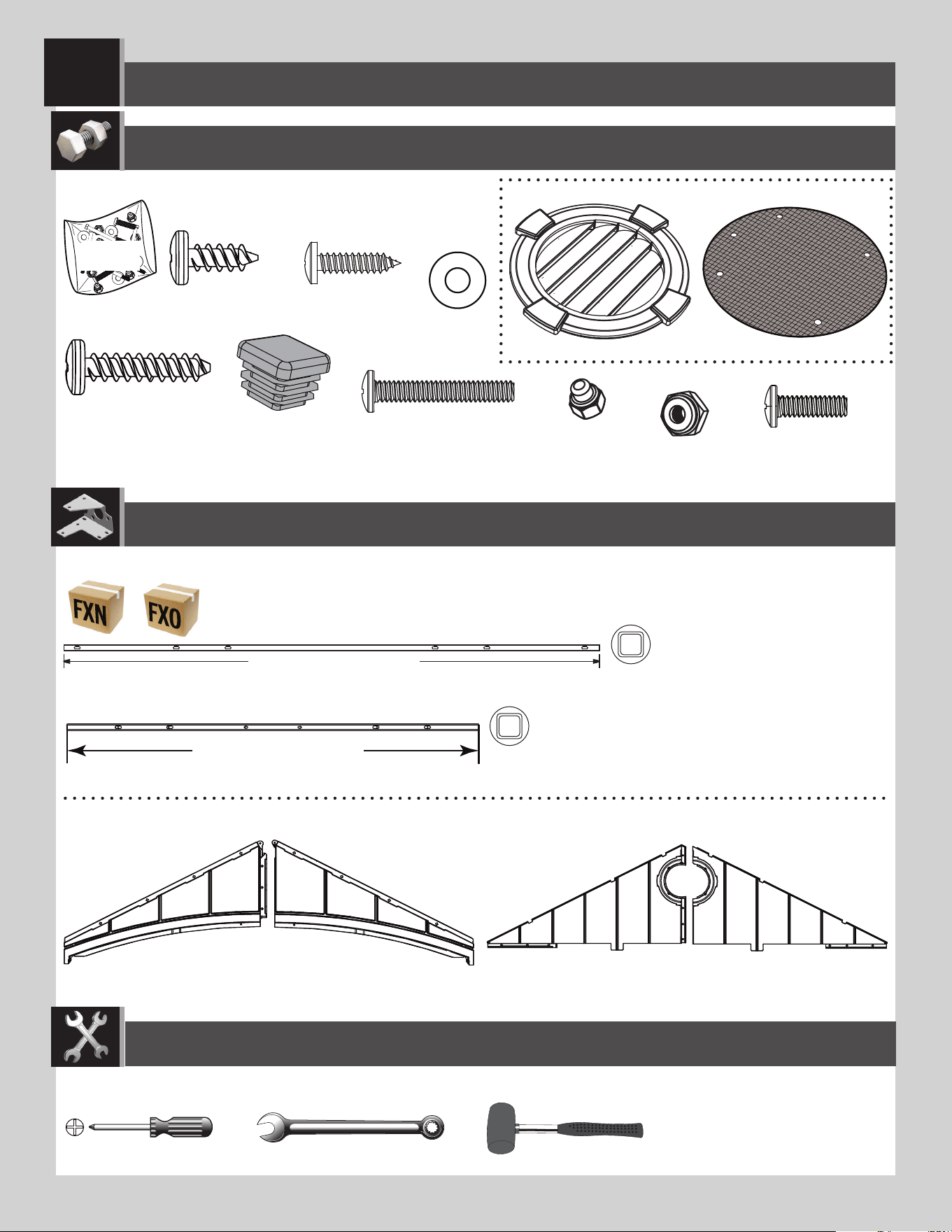
Parts identifi er..............................................................6
Platform construction.................................................10
Truss assembly...........................................................15
Gable assembly...........................................................24
Door assembly............................................................31
Floor assembly............................................................45
Wall assembly.............................................................50
Roof assembly............................................................61
Shelving installation....................................................86
Wall hook installation.................................................91
Door alignment...........................................................93
Anchoring.................................................96
Cleaning & care..........................................................99
Registration.............................................100
Warranty.................................................101
TABLE OF CONTENTS
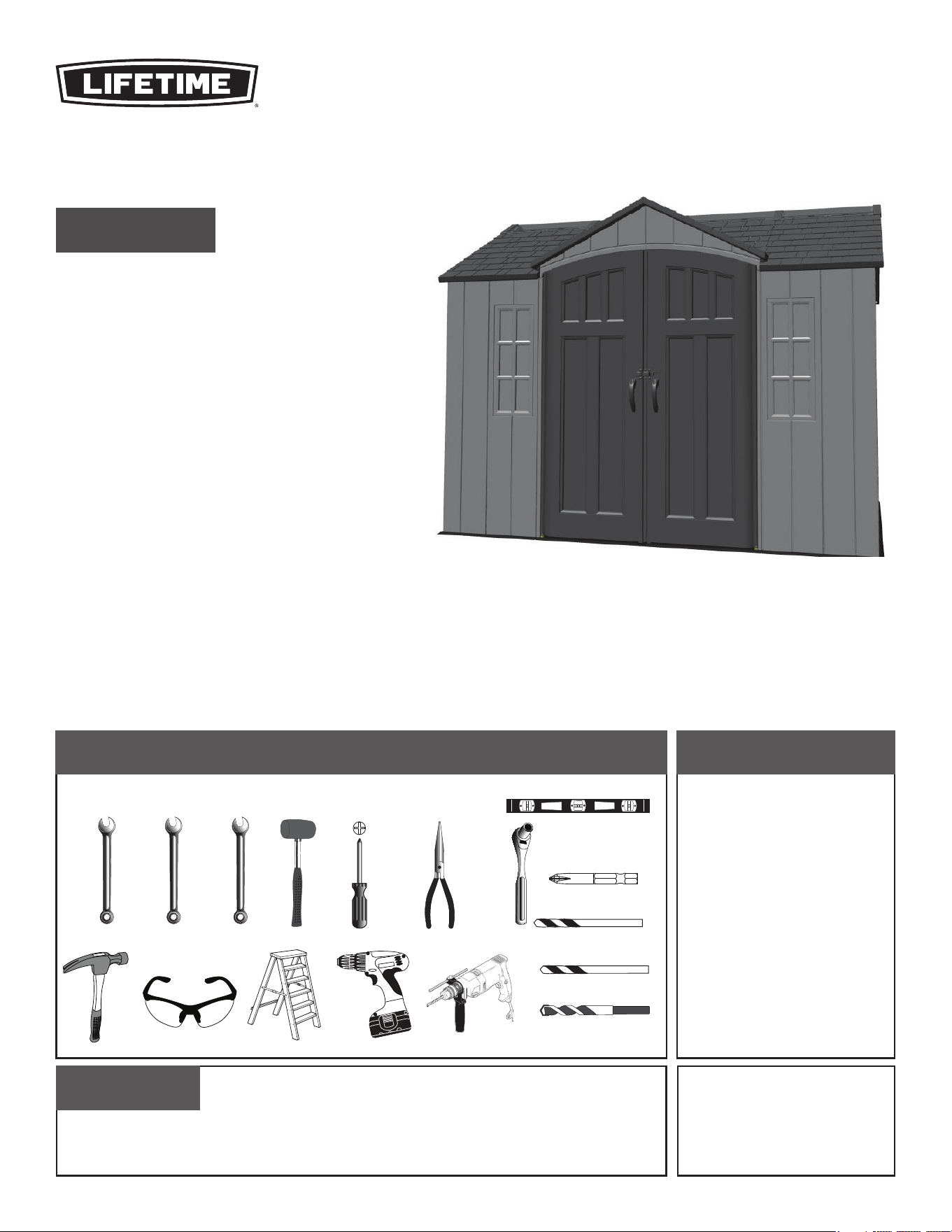
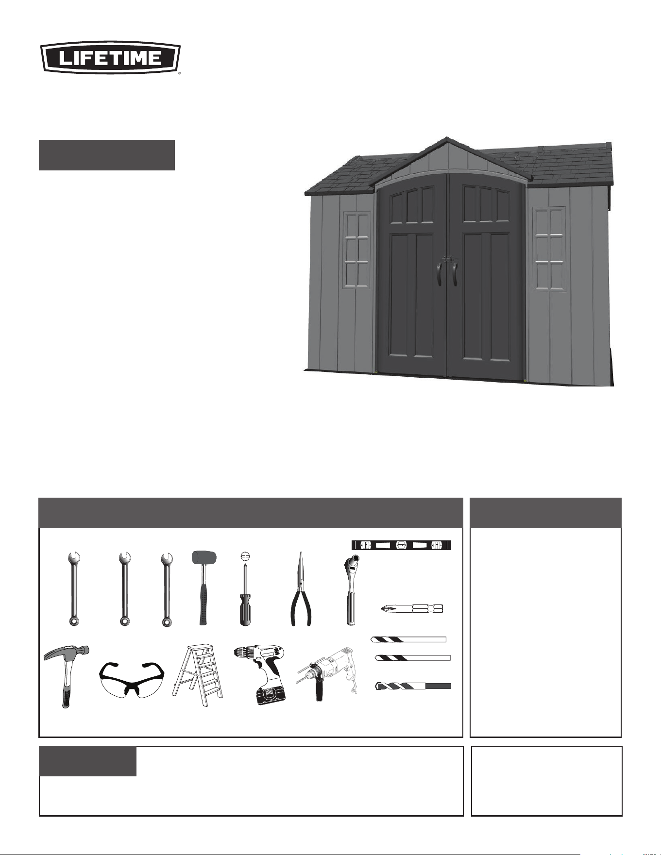
7/16 in (≈11 mm) (x2)
3/8 in (≈10 mm)
5/16 in (≈8 mm) Wood Drill Bit
5/16 in (≈8 mm) Masonry Drill Bit
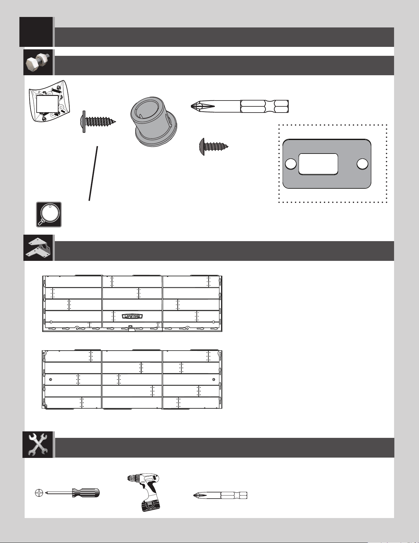
BEFORE ASSEMBLY:
• Assemble on a level platform
• At least 3 adults recommended for setup
• Inspect all parts and hardware. Ensure all are included using the
Parts Identifier
in the middle of these instructions. The
Parts Identifier
, in yellow, can be
removed from the instructions for quick reference
Pour le français, voir la page 2. Para el español, ver la página 3.
ASSEMBLY INSTRUCTIONS
OUTDOOR
STORAGE SHED
MODEL 60453
QUESTIONS?
For Customer Service in mainland
Europe and the United Kingdom:
E-mail: [email protected]
CONTACT LIFETIME CUSTOMER SERVICE:
Call: 1-800-225-3865
(English, French, Spanish)
Live Chat:
www.lifetime.com/customerservice/home
(click on "LIVE CHAT" tab)
Product ID:
FOR DOMESTIC USE ONLY!
IMPORTANT, RETAIN FOR FUTURE REFERENCE: READ CAREFULLY.
TOOLS REQUIRED
(Not included—unless otherwise indicated*)
3/8 in (≈10 mm)
10 mm
ADC (x1)*
ARA (x1) 1/8 in/po (≈3 mm)*
Léegende des icônes....................................................4
Avertissements et avis..................................................5
Identifi cateur des pièces..............................................6
Assemblage de la plate-forme....................................10
Assemblage des fermes..............................................15
Assemblage des pignons.............................................24
Assemblage des portes..............................................31
Assemblage du plancher.............................................45
Assemblage des murs................................................50
Assemblage du toit.....................................................61
Installation du rayonnage............................................86
Installation des crochets muraux...............................91
Alignement des portes................................................93
Ancrage de l’abri.........................................................96
Nettoyage et entretien...............................................99
Enregistrement.............................................100
Garantie...................................................102
AVANT L’ASSEMBLAGE :
• Assembler sur une plate-forme nivelée
• Nous recommandons, au moins, 3 adultes pour l’assemblage
• Examiner toutes les pieces et quincaillerie. Vérifi er qu’elles sont incluses en utilisant
l’
Identifi cateur de pièces
au milieu de ces instructions. Il est posssible enlever
l’
Identifi cateur de pièces
, en jaune, des instructions pour référence rapide
For English, see page 1. Para el español, ver la página 3.
INSTRUCTIONS D’ASSEMBLAGE
REMISE
EXTÉRIEURE
MODÈLE n° 60453
SOMMAIRE
7/16 po (≈11 mm) (x2)
3/8 po (≈10 mm)
5/16 po (≈8 mm) Foret à boit
5/16 po (≈8 mm) Foret à maçonnerie
POUR L’USAGE DOMESTIQUE SEULEMENT !
IMPORTANT, CONSERVER POUR RÉFÉRENCE : LIRE AVEC PRUDENCE !
KONTAKTIEREN SIE DEN KUNDENDIENST VON LIFETIME:
Telefon: 1-800-225-3865
FRAGEN?
Produkt-ID:
Live-Chat:
www.lifetime.com/customerservice/home
.OLFNHQ6LHDXIGLH6FKDOWÀlFKH³/,9(&+$7´
E-Mail Kundendienst europäisches
Festland und Vereinigtes Königreich:
OUTILS REQUIS
(Non inclus — sauf indication contraire*)
10 mm
ADC (x1)*
ARA (x1) 1/8 in/po (≈3 mm)*
3/8 in (≈10 mm)
Leyenda de íconos........................................................4
Advertencias y avisos..................................................5
Identifi cador de piezas.................................................6
Ensamblaje de la plataforma.......................................10
Ensamblaje de las cerchas..........................................15
Ensamblaje de las fachadas........................................24
Ensamblaje de las puertas.........................................31
Ensamblaje del piso....................................................45
Ensamblaje de los muros............................................50
Ensamblaje del tejado.................................................61
Instalación de los estantes........................................86
Instalación de los accesorios......................................91
Alineación de las puertas............................................93
Anclaje de la caseta.....................................................96
Limpieza y cuidado....................................................99
Registro...................................................100
Garantía...................................................103
ANTES DE ENSAMBLAR:
• Ensamblar sobre una plataforma nivelada
• Recomendamos, al menos, 3 adultos para el ensamblaje
• Inspeccionar todas las piezas y el herraje. Verificar que todos están
incluidos usando el
Identificador de piezas
en el medio de las instrucciones.
Se puede quitar el
Identificador de piezas
, en amarillo, de las instrucciones
para referencia rápida
For English, see page 1. Pour le français, voir la page 2.
INSTRUCCIONES DE ENSAMBLAJE
CASETA
ALMACENADORA
MODELO n° 60453
ÍNDICE
7/16 in. (≈11 mm) (x2)
3/8 in. (≈10 mm)
5/16 in. (≈8 mm) Broca para madera
5/16 in. (≈8 mm) Broca de albañilería
¡SÓLO PARA USO DOMÉSTICO!
¡IMPORTANTE, GUARDAR PARA FUTURA REFERENCIA: LEER CUIDADOSAMENTE!
PONERSE EN CONTACTO CON LOS SERVICIOS DE CLIENTES LIFETIME
®
:
Llamar : 1-800-225-3865
(inglés, francés, español)
¿PREGUNTAS?
ID del producto:
Chat en vivo:
www.lifetime.com/customerservice/home
(cliquear en la lengüeta «LIVE CHAT»)
Para el servicio a clientes en el
continente europeo: Correo electrónico:
csinternational@lifetime.com
INSTRUMENTAL REQUERIDO
(No incluido, salvo indicación contratia*)
10 mm
ADC (x1)*
ARA (x1) 1/8 in/po (≈3 mm)*
3/8 in (≈10 mm)
44
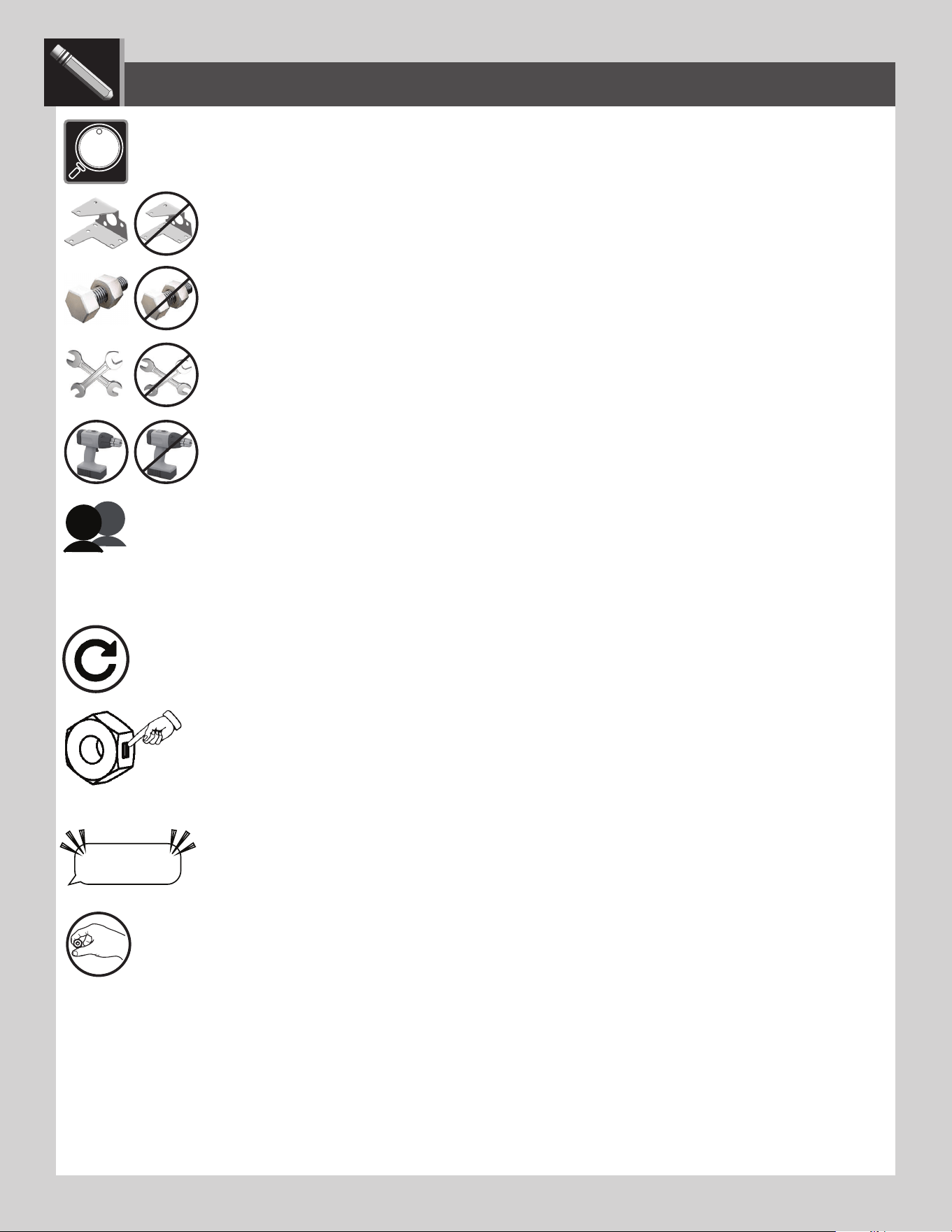
• Indicates the parts (or no parts) required for a section.
• Indique les pièces (ou aucune pièce) à utiliser pour une section.
• Indica las piezas (o ninguna pieza) que se usarán en una sección.
• Indicates special heed should be taken when reading.
• Indique qu’une attention spéciale doit être portée à la lecture.
• Indica que uno debe prestar atención al leer.
• Indicates the tools (or no tools) to be used for a section.
• Indique les outils (ou aucun outil) à utiliser pour une section.
• Indica las herramientas (o ninguna herramienta) que se utilizarán para una sección.
• Indicates the number of adults required to perform a specifi c step, e.g., 2, 3, 4, etc. You may be able to do certain steps by
yourself but, for safety reasons, it’s best to have two or more adults. And...it’s always easier with one or two helpers.
• Indique le nombre d’adultes requis pour e ectuer une étape spécifi que, p. ex., 2, 3, 4, etc. Il est possible de réaliser
certaines étapes seul mais, pour des raisons de sécurité, il est préférible d’être au moins deux adultes. Et... c’est toujours plus facile avec un assistant ou deux.
• Indica el número de adultos requeridos para realizar un paso específi co, p.ej., 2, 3, 4, etc. Es posible realizar unos pasos
solo mas, por razones de seguridad, es mejor tener dos adultos o más. Y... siempre es más fácil con un ayudante o dos.
• Indicates to repeat a step or an action.
• Indique de répéter une étape ou une action.
• Indica repetir un paso o una acción.
• Indicates a specifi c step is harder to perform.
• Indique qu’une étape spécifi que est plus di cile à exécuter.
• Indica que un paso específi co es más difícil de realizar.
• Indicates the hardware (no new hardware) required for a specifi c page or section.
• Indique la quincaillerie (ou aucune nouvelle quincaillerie) n’est requis pour une page précise.
• Indica el herraje (que no se necesita nuevo herraje) para una página específi ca.
• Indicates to use/not use an electric drill for a specifi c step.
• Indique quand utiliser une/que ne pas utiliser de perceuse électrique pour une étape précise.
• Indica la utilización de/que no utilizar un taladro eléctrico para un paso específi co.
ICON LEGEND / LÉGENDE DES ICÔNES / LEYENDA DE ÍCONOS
• Indicates the use of a centerlock nut. A nut with this marking will require some e ort to tighten. This
hardware was designed with this feature in order to prevent loosening later.
• Cette image indique l’usage d’un écrou de blocage central. Un écrou avec ce marquage requerra plus
d’e ort pour le serrer. Cet écrou a été conçu avec cette fonction afi n d’empêcher son desserrage plus tard.
• Indica el uso de una tuerca de bloque central. Una tuerca con esta marca requerirá un poco de esfuerzo para
apretarlo. Esta tuerca fue diseñada con esta característica con el fi n de evitar su afl ojamiento más tarde.
“$#@*%!”
LIFETIME
®
• Indicates that one should only hand-tighten the hardware until instructed otherwise.
• Indique qu’il ne faut serrer la quincaillerie qu’à la main jusqu’à ce que l’on reçoive des instructions contraires.
• Indica que sólo se debe apretar a mano el herraje hasta que indique lo contrario.

55
English:
• Failure to follow these warnings may result in serious injury or property damage and will void warranty.
• To ensure safety, do not attempt to assemble this product without following the instructions carefully.
• Consult all local building codes to verify if the shed requires a building permit.
• Verify the platform foundation is completely level before assembling the shed.
• Be aware that plastic pieces can be damaged by overtightening the screws. To avoid damage, we strongly recommend the use of a drill
with a low torque setting. A #2 Phillips screwdriver may also be used.
• Three capable adults are required for assembly.
• All who participate in the assembly process should wear safety glasses throughout the assembly.
• If using a ladder during assembly, use extreme caution.
• In heavy snowfall areas, we recommend removing snow from the roof. Remove the snow from the roof when the depth of snow
equals the length of your hand.
• Do not use or store hot objects near the product.
• Proper and complete assembly are essential to reduce the risk of accident or injury.
• When drilling through metal, beware of burrs, shavings and other sharp edges.
• During and after assembly, do not slide or lift the shed by pushing up on the roof. Move the shed by pushing on the corner panels only.
•
Failure to anchor the shed may result in property damage and/or personal injury. The last section, Shed Anchoring, in this manual shows the
hardware you will need to complete the anchoring. You can fi nd the hardware at your local hardware store.
• Most injuries are caused by misuse and/or not following instructions. Use caution when using this product.
Français :
• Ne pas suivre ces avertissements peut entraîner des blessures graves ou des dommages à la propriété et annulera la garantie.
• Afi n d’assurer la sécurité, ne pas tenter d’assembler ce produit sans suivre attentivement les instructions.
• Consulter tous les codes du bâtiment afi n de vérifi er si l’abri nécessite un permis de construire.
• Vérifi er que la fondation de la plate-forme est complètement à niveau avant l’assemblage de l’abri.
• Ne pas oublier que les pièces de plastique peuvent être endommagées en serrant trop les vis. Afi n d’éviter les dommages, nous
recommandons fortement l’utilisation d’une perceuse à faible couple. Un tournevis cruciforme nº 2 peut aussi être utilisé.
• Trois adultes en bonne condition physique sont nécessaires pour l’assemblage.
• Tout ceux qui participent au processus de l’assemblage doivent porter des lunettes de sécurité tout au long de l’assemblage.
• Si une échelle est utilisée pour l’assemblage, il faut être extrêmement prudent.
• Dans les zones de fortes tombées de neige, il est recommandé de dégager le toit. Enlever la neige du toit quand la profondeur est égale
à la longueur de la main.
• Ne pas utiliser ou entreposer des objets très chauds près de ce produit.
• Un bon assemblage complet est nécessaire pour réduire le risque d’accident ou de blessure.
• En perçant le métal, faire attention aux bavures, copeaux et autre bords aiguisés.
• Pendant et après l’assemblage, ne pas faire glisser ou soulever l’abri en poussant le toit vers le haut. Déplacer l’abri en poussant les
panneaux muraux angulaires seulement.
• Si vous n’ancrez pas votre abri, des dommages à la propriété et/ou des blessures peuvent en résulter. La dernière section, Ancrage de l’abri, de
ce manuel indique les matériaux nécessaires pour l’ancrage. Les matériaux se trouvent dans la quincaillerie locale.
• La majorité des blessures sont causées par une mauvaise utilisation et/ou le non suivi des instructions. Étre prudent en utilisant ce produit.
Español:
• No seguir estas advertencias puede resultar en lesiones graves o daños a la propiedad y anulará la garantía.
• A fi n de garantizar la seguridad, no intentar ensamblar este producto sin seguir cuidadosamente las instrucciones.
• Consultar todos los códigos de construcción locales para verifi car si el cobertizo requiere un permiso de construcción.
• Verifi car que el concreto de la plataforma esté nivelado completamente antes de ensamblar el cobertizo.
• Tener en cuenta que las piezas de plástico pueden dañarse si los tornillos se aprietan de más. A fi n de evitar daños, lo exhortamos a que
use un taladro con función de torque bajo. También puede usarse un desatornillador Phillips no. 2.
• Se necesitan tres adultos para el ensamble.
• Todos los que participen en el proceso de ensamble debe usar anteojos de seguridad durante todo el ensamble.
• Si se usa una escalera durante el ensamblado, es preciso tener cuidado.
• En áreas de nevadas fuertes, recomendamos retirar la nieve del techo. Quitar la nieve del tejado cuando la profundidad de ella es igual
a la longitud de la mano.
• No usar ni guardar objetos calientes cerca del producto.
• El ensamblaje correcto y completo son esenciales para reducir el riesgo de accidente o lesión.
• Al perforar metal, tenga cuidado las rebabas, virutas y otros bordes afi lados.
• Durante y después del ensamblaje, no deslizar ni levantar el cobertizo para empujar en el tejado. Mover el cobertizo para empujar los
paneles murales angulares solamente.
• No anclar el cobertizo puede resultar en daños a la propiedad y/o en lesiones personales. La última sección, Anclaje de el cobertizo, en este
manual muestra el herraje necesaria para terminar el anclaje. Se encuentra el herraje en la ferretería local.
• La mayoría de las lesiones suceden a causa del mal uso y/o por no seguir las instrucciones. Tener precaución al usar este producto.
WARNINGS & NOTICES / AVERTISSEMENTS ET AVIS / ADVERTENCIAS Y AVISOS
6
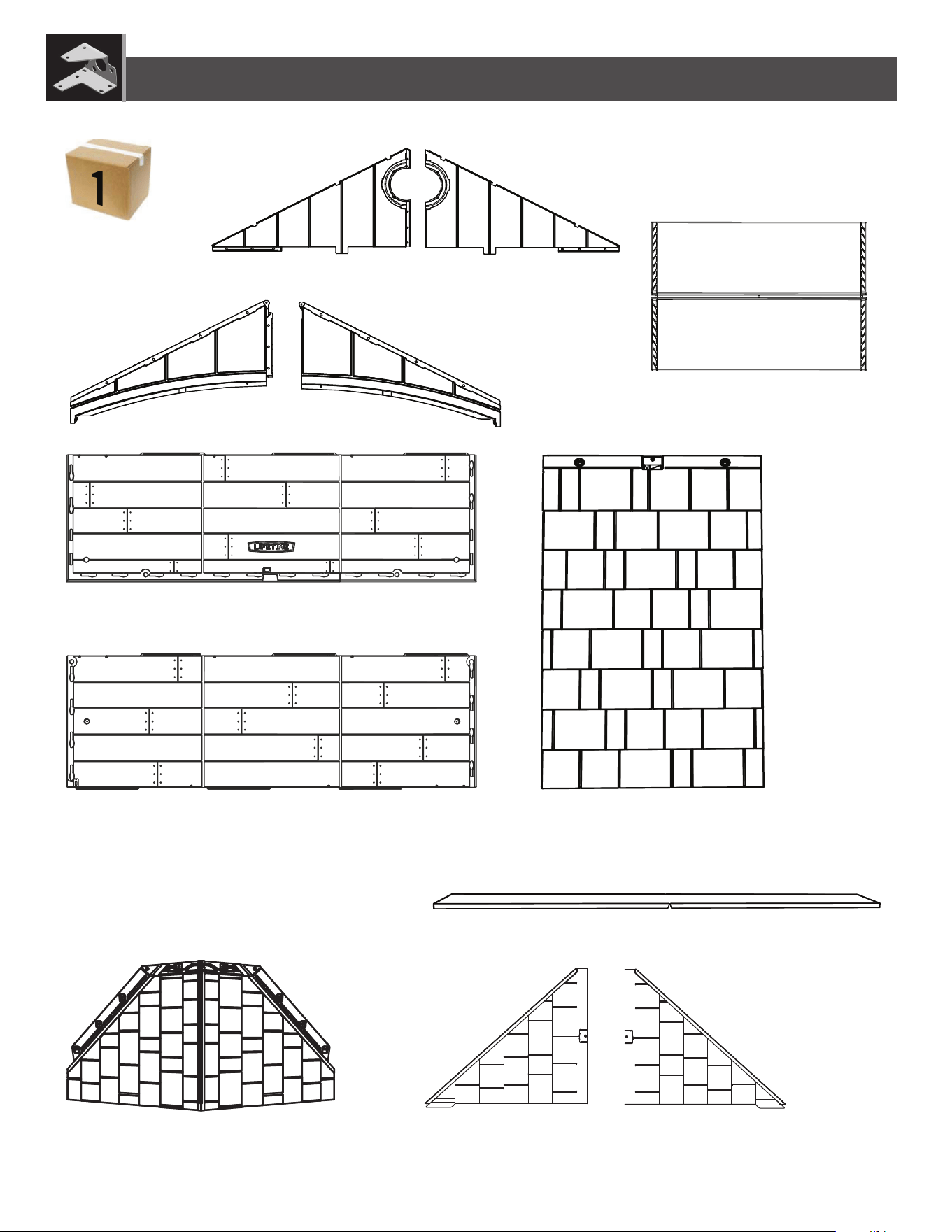
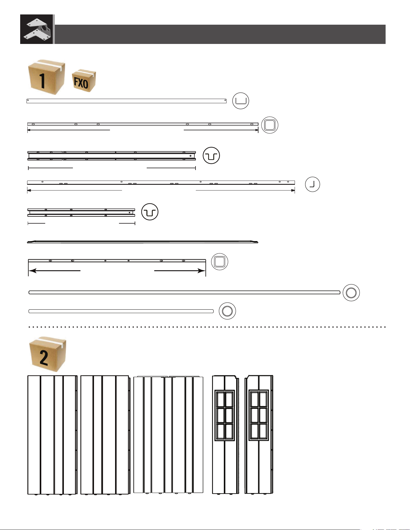
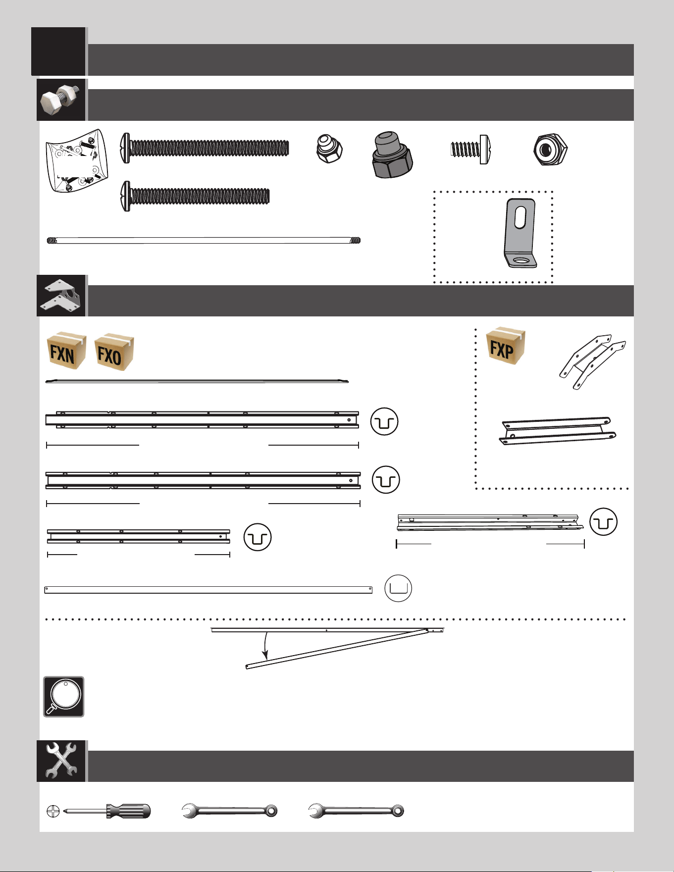
AGH (x2)
AGI (x2)
AGQ (x6)
BDS (x1)
BDR (x1)
AFV (x2)
DRA (x1)
CUW (x2)
CUD (x2)
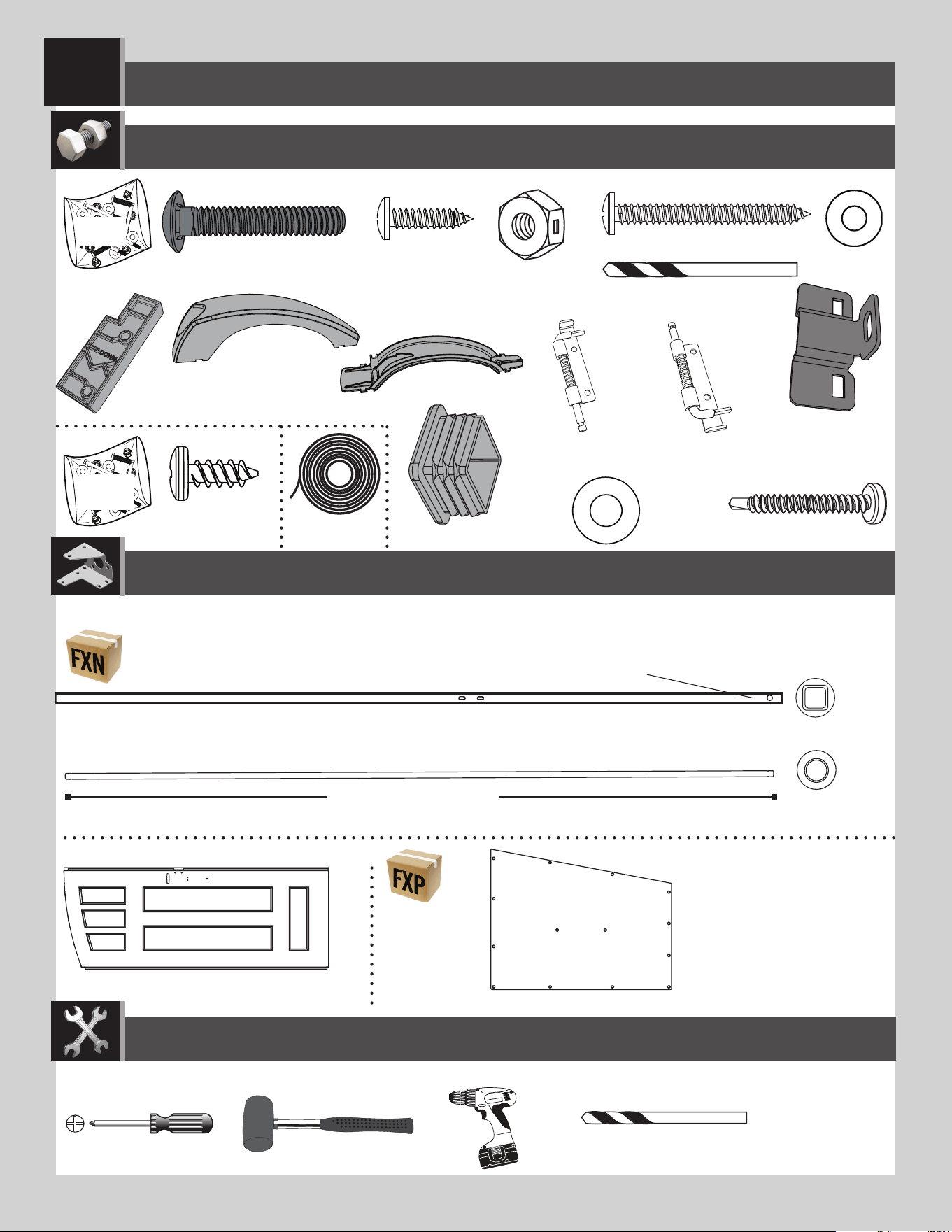
CONTENTS OF BOX 1 / CONTENU DE LA BOITE 1 / CONTENIDO DE LA CAJA 1
PARTS IDENTIFIER / IDENTIFICATEUR DE PIÈCES / IDENTIFICADOR DE PIEZAS
FTM(x1)
FTN (x1)
HLF (x4)
7
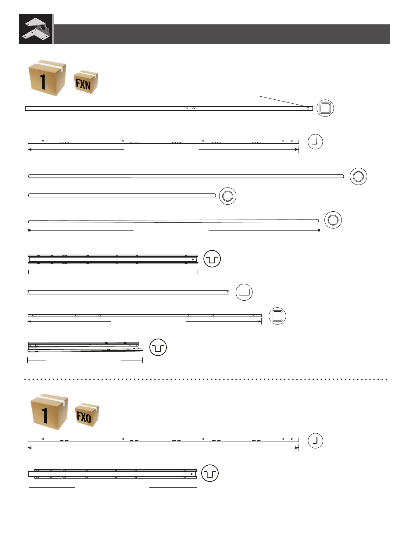
AFG (x1)
CRE (x2)
DSR (x2)
DSQ (x2)
METAL PARTS KIT 1 / TROUSSE DE PIÈCES EN MÉTAL 1 / KIT DE PIEZAS DE METAL 1
PARTS IDENTIFIER / IDENTIFICATEUR DE PIÈCES / IDENTIFICADOR DE PIEZAS
AFE (x1)
EDW (x2)
AFM (x6)
HDU (x1)
HDT (x1)
METAL PARTS KIT 1 / TROUSSE DE PIÈCES EN MÉTAL 1 / KIT DE PIEZAS DE METAL 1
DSM (x1)
AFM (x3)
Top End / Extrémité supérieure / Extremo superior
67 3/4 in/
p
o (≈1,72 m)
67 3/4 in/po (≈172 cm)
67 3/4 in/
p
o (≈1
,
72 m)
67 3/4 in/po (≈172 cm)
74 1/2 in/po (≈1,89 m)
74 1/2 in/po (≈189 cm)
50 9/16 in/po (≈1,28 m)
50 9/16 in/po (≈128 cm)
50 9/16 in/po (≈1,28 m)
50 9/16 in/po (≈128 cm)
59 1/2 in/
p
o (≈1,51 m)
59 1/2 in/po (≈151 cm)
25 7/8 in/po (≈65,7 cm)
25 7/8 in/po (≈65,7 cm)
8
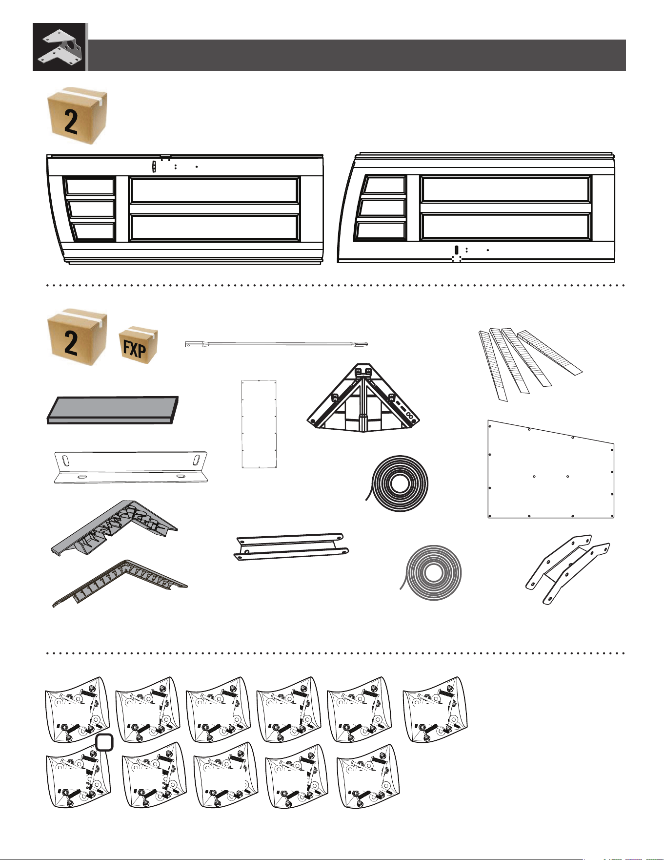
CONTENTS OF BOX 2 / CONTENU DE LA BOITE 2 / CONTENIDO DE LA CAJA 2
PARTS IDENTIFIER / IDENTIFICATEUR DE PIÈCES / IDENTIFICADOR DE PIEZAS
AHD (x7)
AGL (x2)
AGW (x2)
BDH (x1)
BDI (x1)
AFM (x3)
FTW(x1)
HDU (x1)
HDT (x1)
DSO (x1)
DSP (x1)
DSR (x1)
METAL PARTS KIT 1 / TROUSSE DE PIÈCES EN MÉTAL 1 / KIT DE PIEZAS DE METAL 1
AFG (x2)
AFE (x1)
67 3/4 in/
p
o
(
≈1
,
72 m
)
67 3/4 in/po (≈172 cm)
50 9/16 in/po (≈1,28 m)
50 9/16 in/po (≈128 cm)
59 1/2 in/po (≈1,51 m)
59 1/2 in/po (≈151 cm)
34 1/8 in/po (≈86,7 cm)
34 1/8 in/po (≈86,7 cm)
46 in/po (≈1,17 m)
46 in/po (≈117 cm)
9
HEZ ECT
DHL
GHN
EDH
HZA
HKC FXQ
HARDWARE BAGS / SACS DE QUINCAILLERIE / BOLSAS DE HERRAJE
PARTS IDENTIFIER / IDENTIFICATEUR DE PIÈCES / IDENTIFICADOR DE PIEZAS
EWI
BDV (x2)
AFL (x6)
AIP (x3)
AIW (x1)
AIX (x4)
DRB (x1)
CONTENTS OF SMALL PARTS KIT / CONTENU DE LA TROUSSE DE PETITES PIÈCES / CONTENIDO DEL KIT DE PIEZAS PEQUEÑAS
DHN (x2)
HDV (x4)
HOB (x3)
HOC (x2)
DSN (x1)
EPH (x2)
EPI (x2)
2
HKO
EDN
BDK (x1)
BDJ (x1)
CONTENTS OF BOX 2 / CONTENU DE LA BOITE 2 / CONTENIDO DE LA CAJA 2
8 7/16 in/po (≈21,4 cm)
8 7/16 in/po (≈21,4 cm)
1010
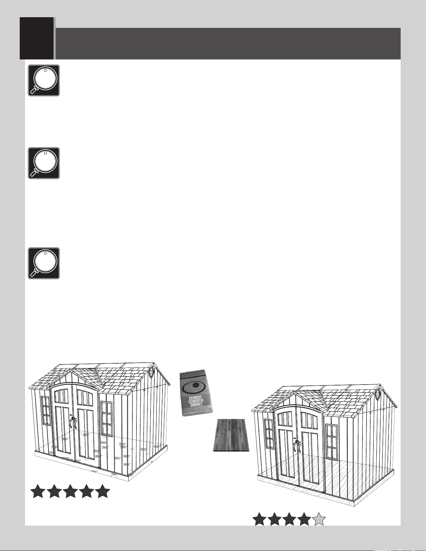
PLATFORM CONSTRUCTION (MATERIALS NOT INCLUDED) / CONSTRUCTION DE LA PLATE-FORME (LES PIÈCES
NE SONT PAS INCLUSES) / CONSTRUCCIÓN DE LA PLATAFORMA (LOS MATERIALES NO SON INCLUIDOS)
1
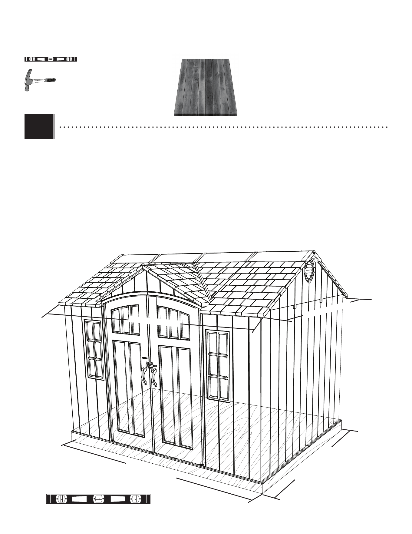
• You must provide a platform on which to assemble your shed. Proper building permit documentation may be
required in your neighborhood. Consult all local building codes prior to assembling the shed. Before beginning
assembly, you must pour or construct a platform. There are two types:
• Concrete
• Wood Frame
Select the type, but know the surface must be leveled before installation. If the surface is not properly leveled, the shed
will not assemble correctly. Proper surface leveling will save you time in the long run, so please do not ignore this step. We
recommend a Concrete platform. It will be the most durable and long-lasting choice. The platform you choose must be built above ground in
order to avoid water pooling inside the shed. All lumber must be rated for outdoor use!
• Il faut construire une plate-forme sur laquelle vous devez assembler votre abri. Il est possible que votre quartier
exige une documentation visant les permis de construire. Consulter tous les codes du bâtiment locaux, ainsi
que les décrets des villes et comtés, pour vérifi er que la construction de l’abri extérieur n’exige pas un permis de
construire. Avant de commencer le montage, il faut couler ou construire une plate-forme. Il y à deux styles :
• Béton
• Cadre à bois
Sélectionner le style, mais savoir que la surface d’installation doit être de niveau. Si la surface n’est pas correctement de
niveau, l’assemblage de l’abri ne se fera pas correctement. On gagnera du temps sur le long terme grâce à une surface bien
de niveau. Ne pas négliger cette étape. Nous recommandons une plate-forme en béton. Ce choix sera le plus durable. La plate-forme
choisie doit être construite au-dessus du sol afi n d’éviter l’accumulation d’eau à l’intérieur de l’abri. Tous le bois d’oeuvre doit être approuvé
pour l’usage à l’extérieur !
• Es preciso construir una plataforma sobre la cual usted debe ensamblar su caseta. Puede suceder que en el
vecindario se requiera la documentación apropiada de un permiso de construcción. Consultar todos los códigos
locales de construcción y los reglamentos de la ciudad y el municipio para asegurarse de que la construcción
de la caseta no requiere un permiso de construcción. Antes de comenzar el ensamble, es necesario verter o
construir una plataforma. Hay dos clases:
• Concreto
• Armazón de madera
Seleccionar la clase, mas saber que la superfi cie debe estar nivelada antes de comenzar el ensamble. Si la superfi cie no está
nivelada de manera adecuada, la caseta no podrá ensamblarse correctamente. La nivelación de la superfi cie ahorrará tiempo
de trabajo, por lo tanto, no ignorar este paso. Recomendamos una plataforma hecho de concreto. Será la elección más perdurable. La
plataforma debe ser construida arriba del suelo para evitar el afl ujo de agua dentro de la caseta. ¡Toda la madera debe estar clasifi cada para el
uso externo!
11
X SECTION 1 (CONTINUED) / SECTION 1 (SUITE) / SECCIÓN 1 (CONTINUACIÓN)
119,6 in/po (≈304 cm)
95,7 in/po (≈243 cm)
94 in/po (≈238,8 cm)
118 in/po (≈299,7 cm)
1 yd
3
(≈0,77 m
3
)
CONCRETE PLATFORM / PLATE-FORME EN BÉTON / PLATAFORMA DE CONCRETO
CONCRETE REQUIRED / BÉTON REQUIS / CONCRETO REQUERIDO
1.1
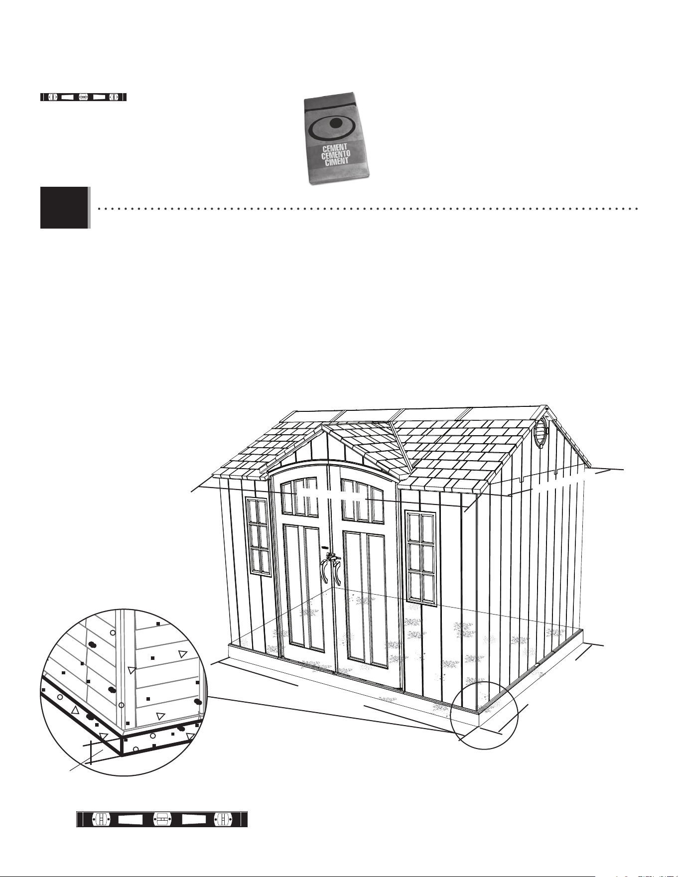
• The concrete should be approximately 4 in (≈10,2 cm) thick. The actual dimensions of the shed, at its widest and
longest points, are 95.7" x 119.6" (≈243 cm x ≈304 cm). Ensure you select a site that will accommodate these
measurements. The fl oor dimensions are a bit smaller than those of the roof; therefore, you will need to build a level platform of, at
least, 94" x 118" (≈238.8 cm x ≈299.7 cm). These are the measurements of the platform—not the fl oor.
• Le béton doit être un épaisseur de ≈10,2 cm (4 po). Les dimensions réelles de l’abri, aux points les plus large
et long, sont ≈243 cm x ≈304 cm (95,7 po x 119,6 po). Veiller à sélectionner un site qui accommodera ces
dimensions. Les dimensions du plancher de votre abri sont plus petites que le toit; ensuite, il faut créer une surface nivelée d’au
moins ≈238,8 cm x ≈299,7 cm (94 po x 118 po). Ces mesures sont de la plate-forme — non le plancher.
• El concreto debe tener, por lo menos, ≈10,2 cm (4 in) de espesor. Las dimensiones reales de la caseta, a sus
puntos más ancho y largo, son ≈243 cm x ≈304 cm (95,7 in x 119,6 in). Asegurarse de seleccionar un sitio que
acomodará estas medidas. Las dimensiones del piso de la caseta son más pequeñas que el tejado; por lo tanto, se necesita crear
una superfi cie nivelada mínimo de ≈238,8 cm x ≈299,7 cm (94 in x 118 in). Estas medidas son las de la plataforma, no el piso.
4 in/po (≈10 cm)
12
X SECTION 1 (CONTINUED) / SECTION 1 (SUITE) / SECCIÓN 1 (CONTINUACIÓN)
WOOD PLATFORM / PLATE-FORME EN BOIS / PLATAFORMA DE MADERA
1.2
WOOD REQUIRED / BOIS REQUIS / MADERA REQUERIDA
119.6 in/po (≈304 cm)
95.7 in/po (≈243 cm)
94 in/po (≈238,8 cm)
118 in/po (≈299,7 cm)
• All lumber must be rated for outdoor use! The actual dimensions of the shed, at its widest and longest points, are 95.7"
x 119.6" (≈243 cm x ≈304 cm). Ensure you select a site that will accommodate these measurements. The fl oor
dimensions are a bit smaller than those of the roof; therefore, you will need to build a level platform of, at least, 94" x 118" (≈238,8 cm x
≈299,7 cm). These are the measurements of the platform—not the fl oor.
• Tous le bois d’oeuvre doit être approuvé pour l’usage à l’extérieur ! Les dimensions réelles de l’abri, aux points les plus
large et long, sont ≈243 cm x ≈304 cm (95.7 po x 119.6 po). Veiller à sélectionner un site qui accommodera ces
dimensions. Les dimensions du plancher de votre abri sont plus petites que le toit; ensuite, il faut créer une surface nivelée d’au
moins ≈238,8 cm x ≈299,7 cm (94 po x 118 po). Ces mesures sont de la plate-forme — non le plancher.
• ¡Toda la madera debe estar clasifi cada para el uso externo! Las dimensiones reales de la caseta, a sus puntos más ancho
y largo, son ≈243 cm x ≈304 cm (95.7 in x 119.6 in). Asegúrese de seleccionar un sitio que acomodará estas
medidas. Las dimensiones del piso de la caseta son más pequeñas que el tejado; por lo tanto, se necesita crear una superfi cie nivelada
mínimo de ≈238,8 cm x ≈299,7 cm (94 in x 118 in). Estas medidas son las de la plataforma, no el piso.
13
X SECTION 1 (CONTINUED) / SECTION 1 (SUITE) / SECCIÓN 1 (CONTINUACIÓN)
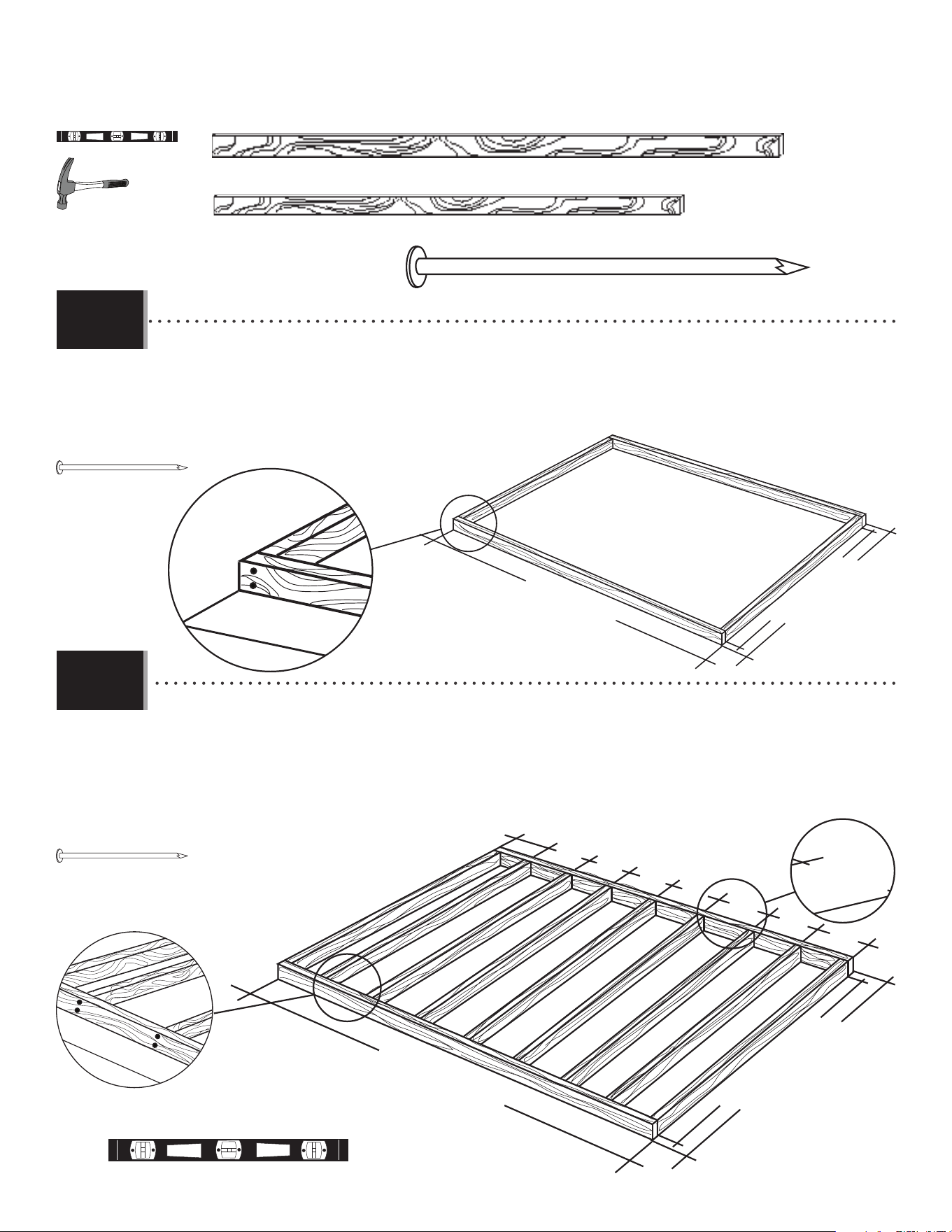
2 in/po x 4 in/po x 91 in/po (≈5 cm x ≈10 cm x ≈231,2 cm) (x9)
2 in/po x 4 in/po x 118 in/po (≈5 cm x ≈10 cm x ≈299,7 cm) (x2)
16d 3 1/2 in/po (16 mm dia. x ≈8,89 cm) (x36)
• To ensure studs are in the correct location for nailing plywood in the next step, start measuring from the
corner 16" (≈40,6 cm), and then measure from center to center.
• Pour être sûr d’avoir assez de montant pour clouer le contreplaqué dans le prochaine étape, commencer à
mesurer à partir de cette montant ≈40,6 cm (16 po) vers le centre du deuxième montant. Ensuite, mesurer
de centre à centre pour les montants restants.
• Para asegurarse que los montantes están en las ubicaciones correctas para el contrachapado en el paso
siguiente, comenzar a medir desde el borde del montante hasta el centro del próximo montante ≈40,6 cm
(16 in). Luego, tomar la medida de centro a centro en los montantes restantes.
118 in/po (≈299,7 cm)
94 in/po (≈238,8 cm)
91 in/po (≈231,2 cm)
x8
x28
16 in/po (40,6 cm)
118 in/po (≈299,7 cm)
94 in/po (≈238,8 cm)
91 in/po (≈231,2 cm)
16 in
(40,6 cm)
16 in
(40,6 cm)
16 in
(40,6 cm)
16 in
(40,6 cm)
16 in
(40,6 cm)
16 in
(40,6 cm)
16 in
(40,6 cm)
• Ensure all lumber is treated and approved for outdoor use. Build frame to 94" x 118"
• (≈238,8 cm x ≈299,7 cm) (outside dimensions).
• Vérifi er que votre bois d’œuvre à été traité et approuvé pour l’utilisation à l’extérieur. Construire un cadre de
≈238,8 cm x ≈299,7 cm (94 po x 118 po) (dimensions extérieures).
• Asegurar que use madera tratada y aprobada para el uso externo. Construir el armazón a ≈238,8 cm x ≈299,7
cm (94 in x 118 in) (dimensiones exteriores).
1.2.1
1.2.2
TOOLS AND PARTS REQUIRED / OUTILS ET PIÈCES REQUIS / INSTRUMENTAL Y PIEZAS REQUERIDOS
14
X SECTION 1 (CONTINUED) / SECTION 1 (SUITE) / SECCIÓN 1 (CONTINUACIÓN)
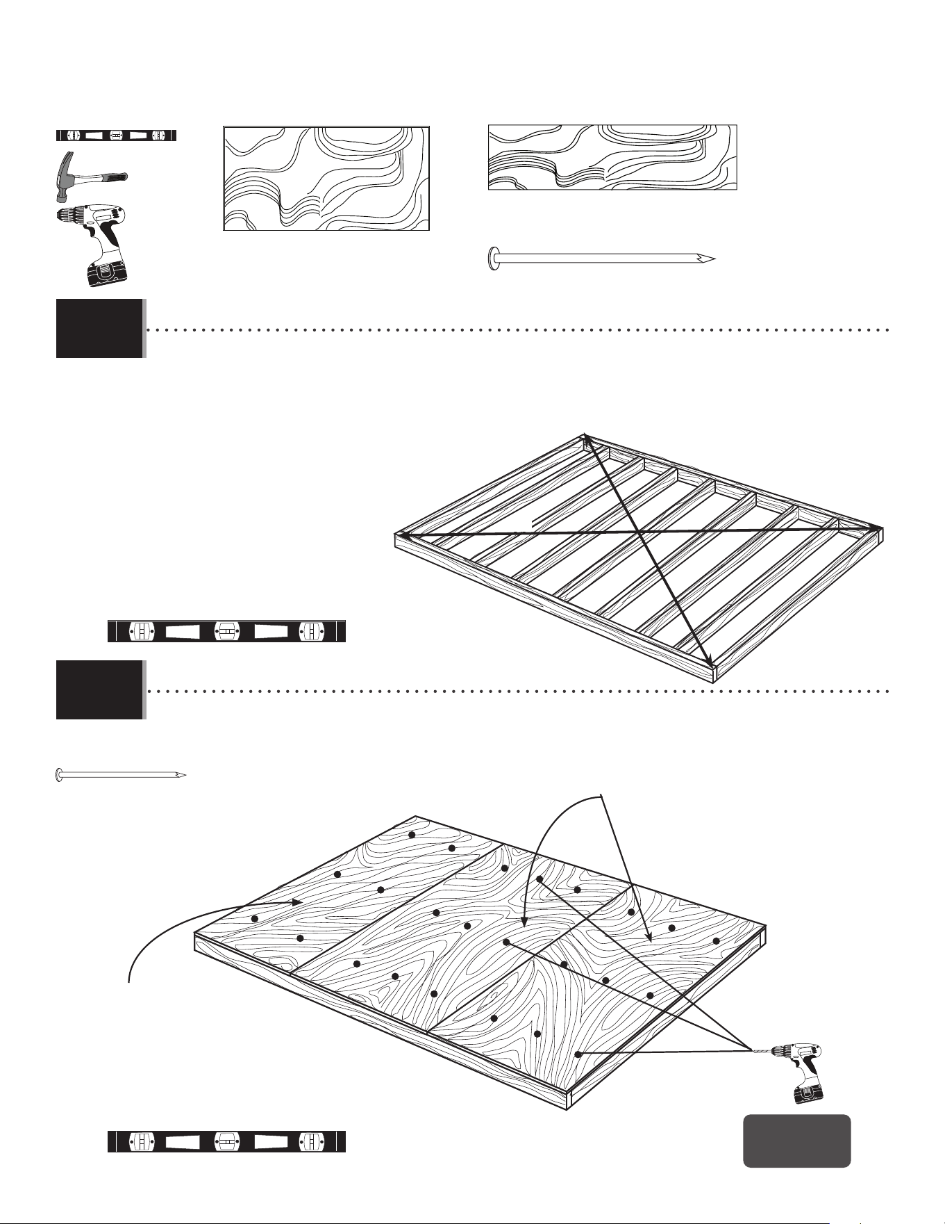
8 mm dia. 2 1/2 in/po (8d ≈6,35 cm) (x66)
48 in/po x 94 in/po x 0.75 in/po
(≈121,9 cm x ≈238,8 cm x ≈19,1 mm) (x2)
22 in/po x 94 in/po x 0.75 in/po
(≈55,9 cm x ≈238,8 cm x ≈19,1 mm) (x1)
22 in/po x 94 in/po x 0.75 in/po
(≈55,9 cm x ≈238,8 cm x ≈19,1 mm)
48 in/po x 94 in/po x 0.75 in/po
(≈121,9 cm x ≈238,8 cm x ≈19,1 mm)
x66
A = B
A
B
x24!
• Drainage holes
• Trous de drainage
• Agujeros para canalización
• Square the frame measuring from corner to corner.
• Carrer le cadre en mesurant d’angle à angle.
• Cuadrar el armazón midiendo de esquina a esquina.
• Using nails, fasten the plywood to the frame. Then, drill 3/8” (≈4 mm) holes for drainage.
• En utilisant des clous, fi xer bien le contreplaqué au cadre. Ensuite, percer des trous de drainage de ≈4 mm (3/8”).
• Usando unos clavos, fi jar el contrachapado al armazón. Entonces, taladrar agujeros para el drenaje de ≈4 mm (3/8”).
1.2.3
1.2.4
TOOLS AND PARTS REQUIRED / OUTILS ET PIÈCES REQUIS / INSTRUMENTAL Y PIEZAS REQUERIDOS
1515
TRUSS ASSEMBLY / ASSEMBLAGE DES FERMES / ENSAMBLAJE DE LAS CERCHAS
2
ADH (x3)
AFG (x3)
DSO (x1)
DSM (x1)
DSN (x1)
DSP (x1)
ADY (x11)
ADK (x24)
ADJ (x6)
AIP (x3)
DTK (x14)
DTJ (x1)
CXK (x2)
AHT (x1)
7/16 in/po (≈11 mm) (x2) 3/8 in/po (≈10 mm)
HKC
Metal parts / Pièces en métal / Piezas de metal
PARTS REQUIRED / PIÈCES REQUISES / PIEZAS REQUERIDAS
HARDWARE REQUIRED / QUINCAILLERIE REQUISE / HERRAJE REQUERIDO
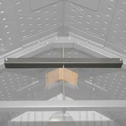
DSQ / DSR
AFG
• Sometimes during shipping, the truss brace (AFG) slides over the back of the truss gutter channel (DSQ or DSR). The two pieces are the same color. If you think you’re missing a
truss brace, check to see if it is stuck to the back of the truss gutter channel, and separate the two.
• Durant le transport, parfois le support de ferme (AFG) glisse par-dessus l’arrière du canal de ferme (DSQ ou DSR). Les deux pièces sont du même colour. Si vous pensez que
vous n’avez pas de support de ferme, vérifi ez s’il y a un support de ferme adhéré à l’arrière du canal de ferme, et séparez les deux.
• Durante el transporte, a veces el soporte de cercha (AFG) deslice sobre el dorso del canalon de cercha (DSQ o DSR). Las dos piezas son de la misma color. Si pienza que le falta
un soporte de cercha, verifi que si haya un soporte pegado al dorso del canalón de cercha, y separe las dos.
DSR (x3)
DSQ (x2)
Parts
Pièces
Piezas
TOOLS REQUIRED / OUTILS REQUIS / INSTRUMENTAL REQUERIDO
(Not included—unless otherwise indicated*) / (Non inclus — sauf indication contraire*) / (No incluido, salvo indicación contraria*)
50 9/16 in/
p
o
(
≈1
,
28 m
)
50 9/16 in/po (≈128 cm)
50 9/16 in/po (≈1,28 m)
50 9/16 in/po (≈128 cm)
34 1/8 in/po (≈86,7 cm)
34 1/8 in/po (≈86,7 cm)
25 7/8 in/po (≈65,7 cm)
25 7/8 in/po (≈65,7 cm)
8 7/16 in/po (≈21,4 cm)
8 7/16 in/po (≈21,4 cm)
16
TOOLS AND HARDWARE REQUIRED / OUTILS ET QUINCAILLERIE REQUIS / INSTRUMENTAL Y HERRAJE REQUERIDOS
X SECTION 2 (CONTINUED) / SECTION 2 (SUITE) / SECCIÓN 2 (CONTINUACIÓN)
ADK (x4)
AIP
DSR
DSQ
ADK (x4)
DTK (x4)
DTK (x4)
3/8 in/po
(≈10 mm)
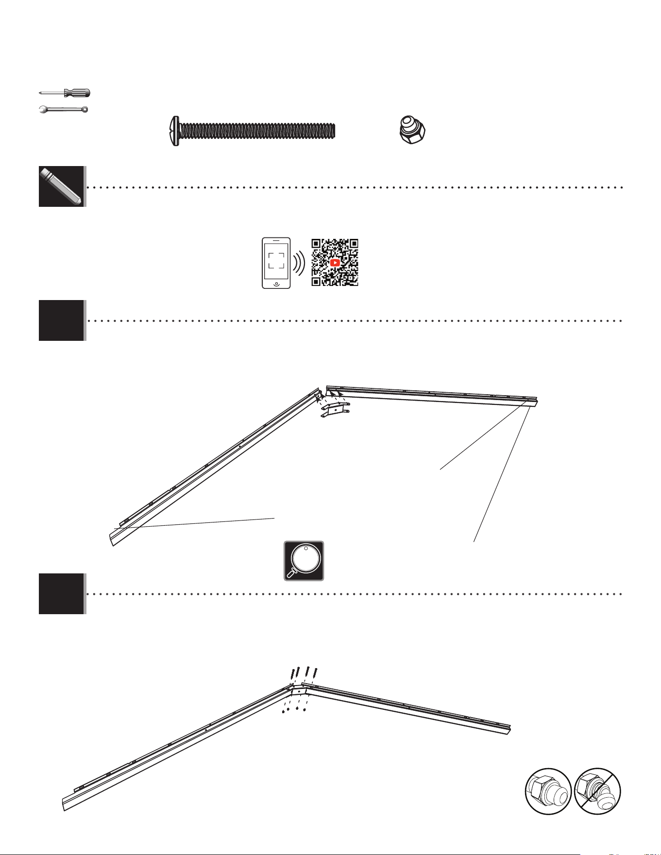
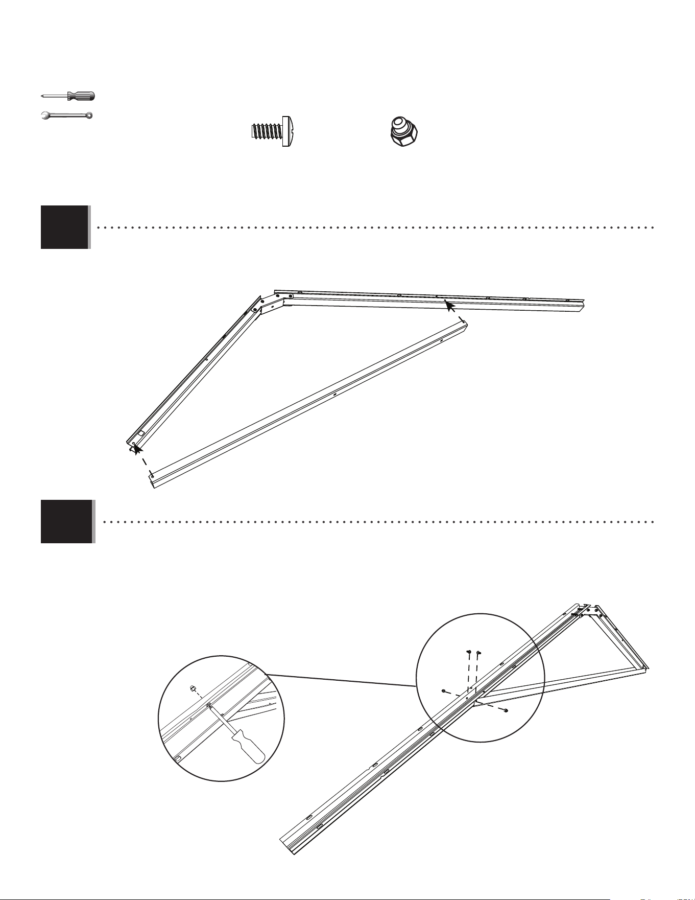
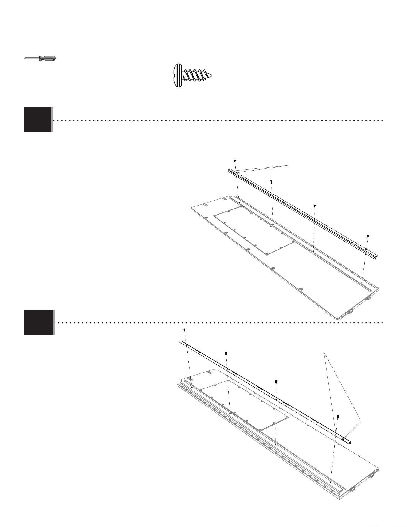
• Attach a connector (AIP) to the end of two truss gutter channels (DSQ & DSR) as shown.
• Attacher un raccord (AIP) à l’extrémité des canaux de gouttière (DSQ & DSR) comme indiqué.
• Sujetar un connector (AIP) a los extremos de los canalones de la cercha (DSQ & DRS) como se muestra.
• Notch
• Encoche
• Muesca
• No notch
• Sans encoche
• Sin muesca
SIDE TRUSSES (x2) / CERCHAS LATERALES (x2) / FERMES LATÉRAUX (x2)
• Channel (DSR) has no notch at the end.
• Le canal (DSR) n’a pas d’encoche à l’extrémité.
• El canalón (DSR) no tiene una muesca al extremo.
2.2
2.1
• Secure a connector (AIP) to the end of the truss gutter channels (DSQ & DSR) as shown.
• Fixer un raccord (AIP) à l’extrémité des canaux de gouttière (DSQ et DSR) comme indiqué.
• Fijar un connector (AIP) a los extremos de los canalones de la cercha (DSQ y DSR) como se muestra.
http://go.lifetime.com/10x8-section2
• In case of any trouble with this section, scan the QR code below to view a video on its assembly.
• En cas de problème avec cette section, scanner le QR code en dessous pour voir une vidéo de l’assemblage.
• En caso de problemas con esta sección, escanear el código QR debajo para ver un video del ensamblaje.
LIFETIME
®
17
TOOLS AND HARDWARE REQUIRED / OUTILS ET QUINCAILLERIE REQUIS / INSTRUMENTAL Y HERRAJE REQUERIDOS
X SECTION 2 (CONTINUED) / SECTION 2 (SUITE) / SECCIÓN 2 (CONTINUACIÓN)
ADY (x4)
ADK (x4)
ADY (x2)
ADY (x2)
ADY
AFG
ADK
ADK
ADK
ADK
ADK
3/8 in/po
(≈10 mm)
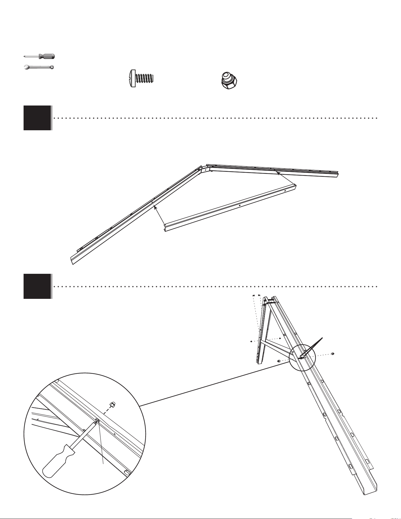
• Slide a truss brace (AFG) onto the truss gutter channels as shown.
• Faire glisser un support de la ferme (AFG) sur les canaux de gouttière comme indiqué.
• Deslizar un soporte de la cercha (AFG) sobre los canalones de la cercha como se muestra.
• Attach the truss brace using the hardware included. Do not
overtighten.
• Attacher le support de la ferme à l’aide de la quincaillerie
incluse. Ne pas serrer excessivement.
• Sujetar el soporte de la cercha usando el herraje incluido. No
apretar demasiado.
2.3
2.4
18
TOOLS AND HARDWARE REQUIRED / OUTILS ET QUINCAILLERIE REQUIS / INSTRUMENTAL Y HERRAJE REQUERIDOS
X SECTION 2 (CONTINUED) / SECTION 2 (SUITE) / SECCIÓN 2 (CONTINUACIÓN)
3/8 in/po
(≈10 mm)
ADJ (x2)
ADJ
ADJ
ADH (x1)
ADH
7/16 in/po
(≈11 mm) (x2)
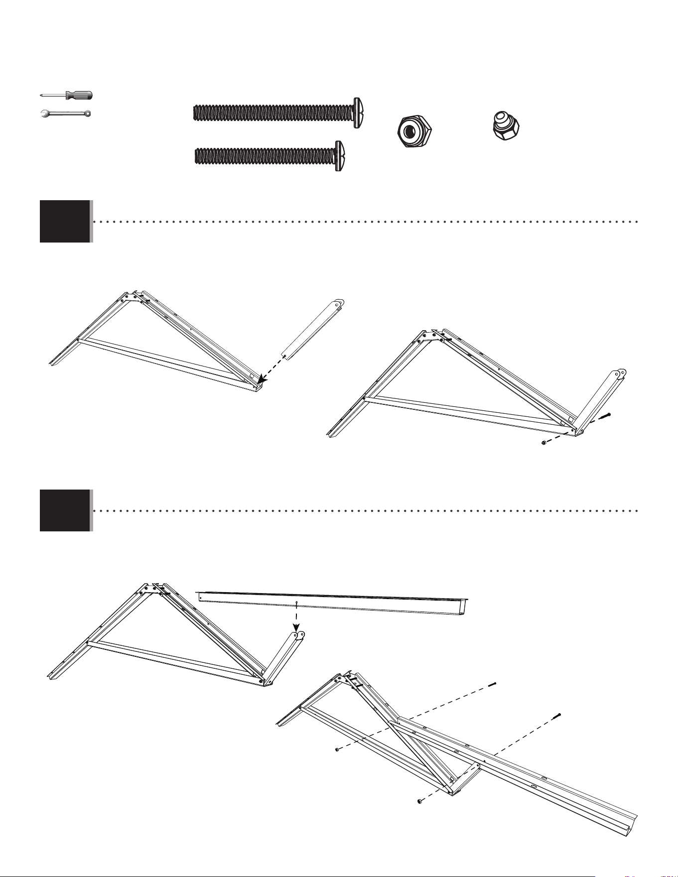
• Slide a truss rod (ADH) through the holes in the brace and
connector. Secure with two cap nuts (ADJ).
• Faire glisser une tige (ADH) à travers les trous dans le support
et le raccord. Bien l’attacher à l’aide de deux écrous borgnes
(ADJ).
• Deslizar una varilla (ADH) a través de los agujeros en el
soporte y el conector. Sujetarla con dos tuercas ciegas (ADJ).
• Repeat the previous steps for a second side truss.
• Répéter les étapes précédentes pour une deuxième ferme latérale.
• Repetir los pasos anteriores para una segunda cercha lateral.
• This notched end will face the front of the shed.
• Cette extrémité encochée fera face à la partie avant de l’abri.
• Este extremo muescado dará a la parte delantera de la caseta.
2.5
2.6
ADY (x4)
ADK (x8)
DTK (x4)
19
TOOLS AND HARDWARE REQUIRED / OUTILS ET QUINCAILLERIE REQUIS / INSTRUMENTAL Y HERRAJE REQUERIDOS
X SECTION 2 (CONTINUED) / SECTION 2 (SUITE) / SECCIÓN 2 (CONTINUACIÓN)
AIP
DSR
DSM
DTK (x4)
ADK (x4)
ADK (x4)
DTK (x4)
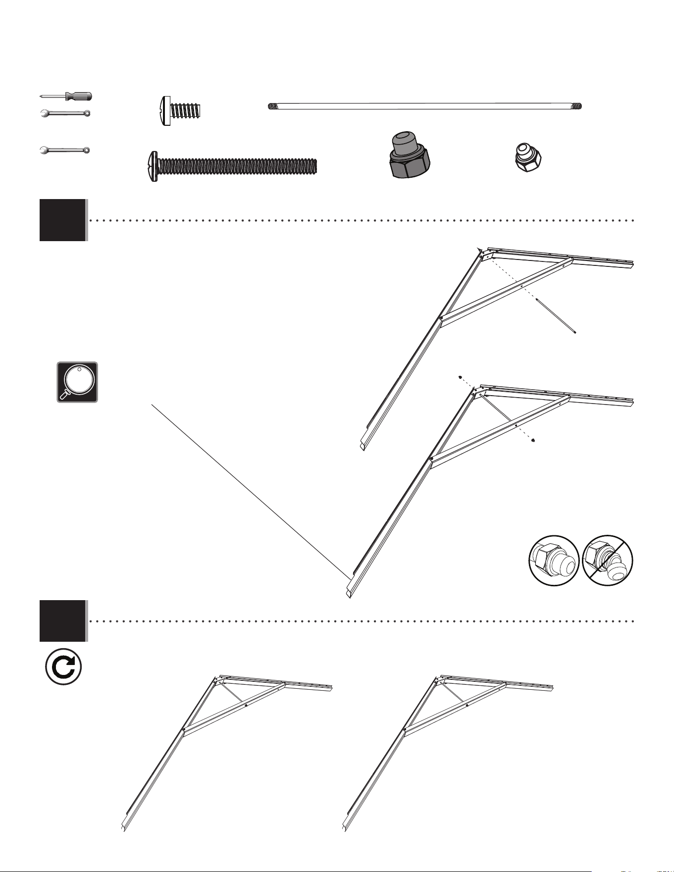
• Attach a connector (AIP) to the end of two truss gutter channels (DSM & DSR) as shown.
• Attacher un raccord (AIP) à l’extrémité des canaux de gouttière (DSM & DSR) comme indiqué.
• Sujetar un connector (AIP) a los extremos de los canalones de la cercha (DSM & DRS) como se muestra.
• Attach a connector (AIP) to the end of two truss gutter channels (DSM, DSR) using the hardware included. Do not overtighten the cap nuts
(ADK).
• Attacher un raccord (AIP) à l’extrémité des canaux de gouttière (DSM, DSR) à l’aide de la quincaillerie incluse. Ne pas trop serrer les
écrous borgnes (ADK).
• Sujetar un connector (AIP) a los extremos de los canalones de la cercha (DSM, DSR) usando el herraje incluido. No apretar demasiado las
tuercas ciegas (ADK).
CENTER TRUSS (x1) / FERME CENTRALE (x1) / CERCHA CENTRAL (x1)
• Channel (DSR) has no notch at the end.
• Le canal (DSR) n’a pas d’encoche à l’extrémité.
• El canalón (DSR) no tiene una muesca al extremo.
!
2.7
2.8
3/8 in/po
(≈10 mm)
20
TOOLS AND HARDWARE REQUIRED / OUTILS ET QUINCAILLERIE REQUIS / INSTRUMENTAL Y HERRAJE REQUERIDOS
X SECTION 2 (CONTINUED) / SECTION 2 (SUITE) / SECCIÓN 2 (CONTINUACIÓN)
ADY (x2)
ADK (x2)
ADK
ADK
3/8 in/po
(≈10 mm)
AFG
ADY (x2)
• Slide a truss brace (AFG) onto the truss gutter channels as shown.
• Faire glisser un support de la ferme (AFG) sur les canaux de gouttière comme indiqué.
• Deslizar un soporte de la cercha (AFG) sobre los canalones de la cercha como se muestra.
• Attach the truss brace using the hardware included. Do not overtighten.
• Attacher le support de la ferme à l’aide de la quincaillerie incluse. Ne pas serrer excessivement.
• Sujetar el soporte de la cercha usando el herraje incluido. No apretar demasiado.
2.10
2.9
21
TOOLS AND HARDWARE REQUIRED / OUTILS ET QUINCAILLERIE REQUIS / INSTRUMENTAL Y HERRAJE REQUERIDOS
X SECTION 2 (CONTINUED) / SECTION 2 (SUITE) / SECCIÓN 2 (CONTINUACIÓN)
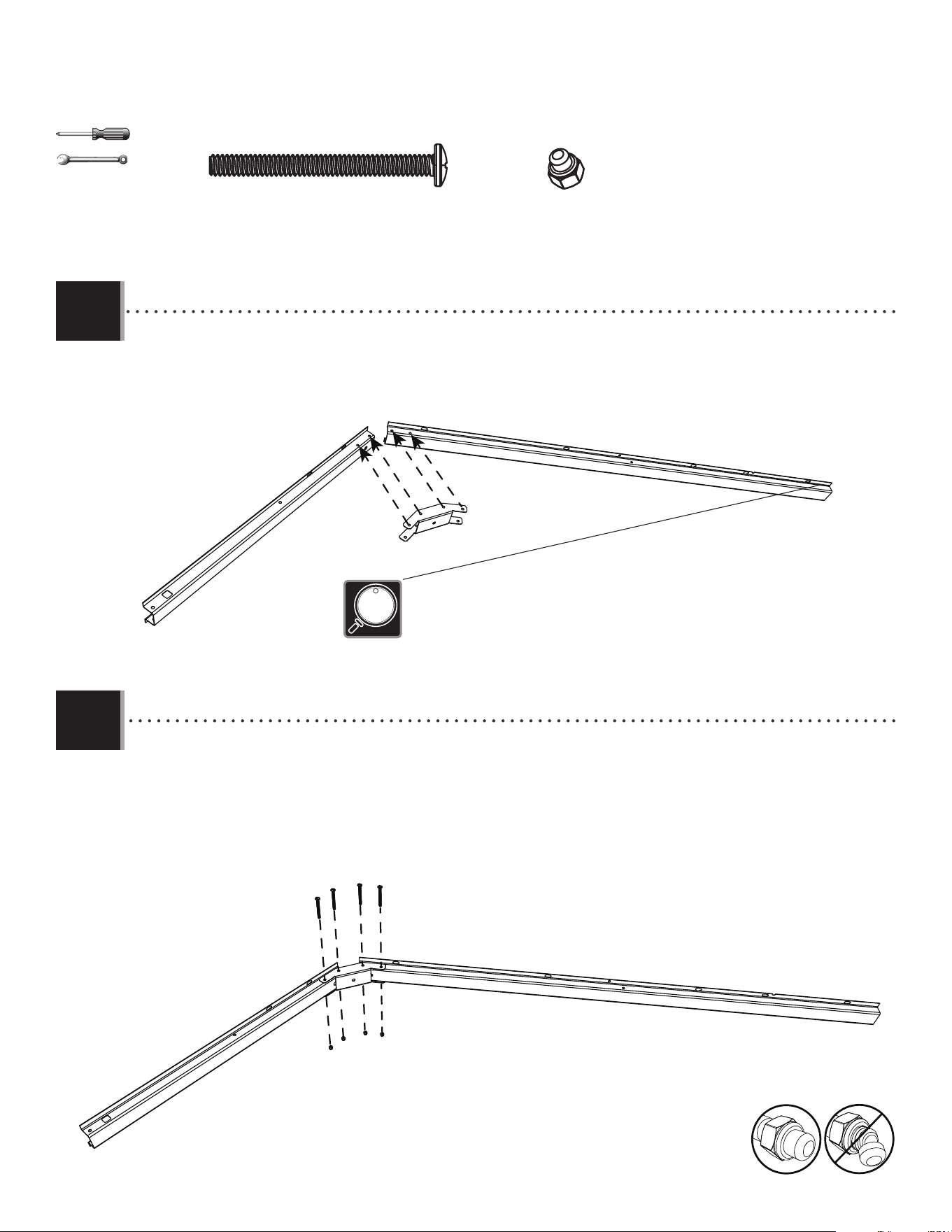
DSN
DTK
ADK
ADK (x1)
DTK (x2)
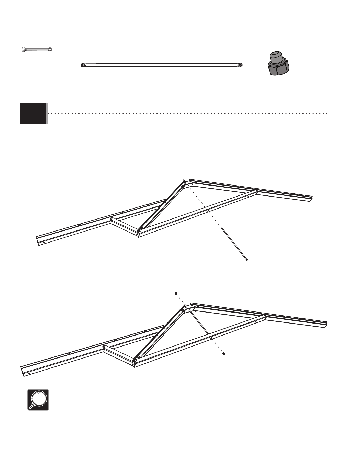
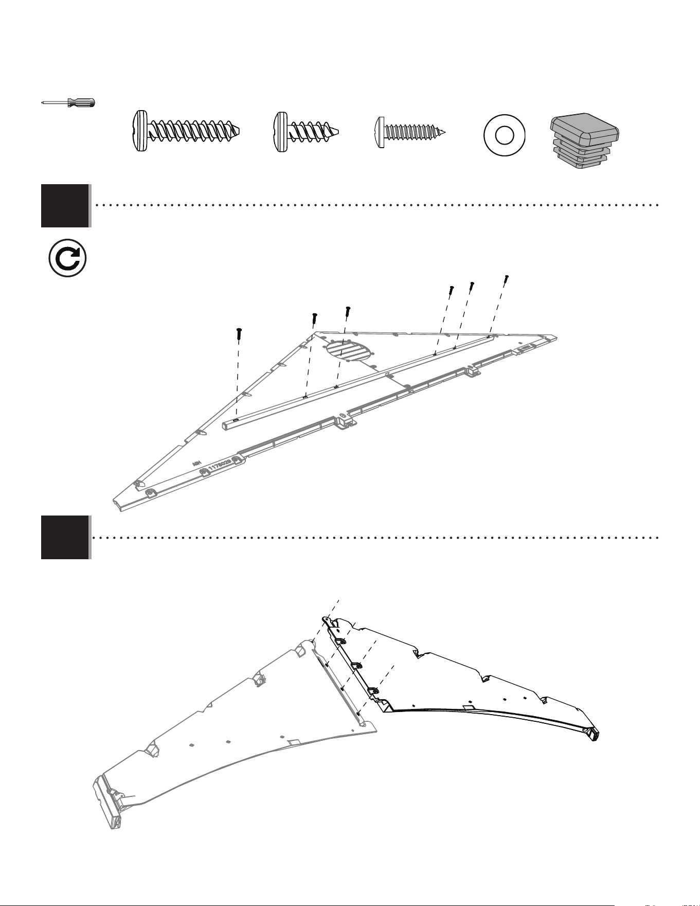
• Attach the vertical truss brace (DSN) to the truss. Only fi nger tighten this nut (ADK) for now.
• Attacher le support vertical (DSN) à la ferme. Serrer l’écrou (ADK) à la main pour le moment.
• Fijar el soporte vertical (DSN) a la cercha. Apretar la tuerca (ADK) a mano por el momento.
• Secure the horizontal truss brace (DSO) to the truss with the hardware included. Now tighten the nut from step 2.11.
• Attacher le support horizontal (DSO) à la ferme à l’aide de la quincaillerie incluse. Maintenant, serrer l’écrou de l’étape 2.11.
• Sujetar el soporte horizontal (DSO) a la cercha usando el herraje incluido. Ahora, apretar la tuerca del paso 2.11.
CXK (x2)
DTJ (x1)
DSO
DTJ
DTK
CXK
CXK
2.11
2.12
3/8 in/po
(≈10 mm)
22
TOOLS AND HARDWARE REQUIRED / OUTILS ET QUINCAILLERIE REQUIS / INSTRUMENTAL Y HERRAJE REQUERIDOS
X SECTION 2 (CONTINUED) / SECTION 2 (SUITE) / SECCIÓN 2 (CONTINUACIÓN)
ADH
ADH (x1)
ADJ
ADJ
ADJ (x2)
7/16 in/po
(≈11 mm) (x2)
• Slide a truss rod (ADH) through the holes in the brace and connector. Secure with two cap nuts (ADJ).
• Faire glisser une tige (ADH) à travers les trous dans le support et le raccord. Bien l’attacher à l’aide de deux écrous
borgnes (ADJ).
• Deslizar una varilla (ADH) a través de los agujeros en el soporte y el conector. Sujetarla con dos tuercas ciegas (ADJ).
• Do not overtighten the cap nuts (ADJ).
• Ne pas trop serrer les écrous à chape (ADJ).
• No apretar demasiado las tuercas ciegas (ADJ).
2.13
23
TOOLS AND HARDWARE REQUIRED / OUTILS ET QUINCAILLERIE REQUIS / INSTRUMENTAL Y HERRAJE REQUERIDOS
X SECTION 2 (CONTINUED) / SECTION 2 (SUITE) / SECCIÓN 2 (CONTINUACIÓN)
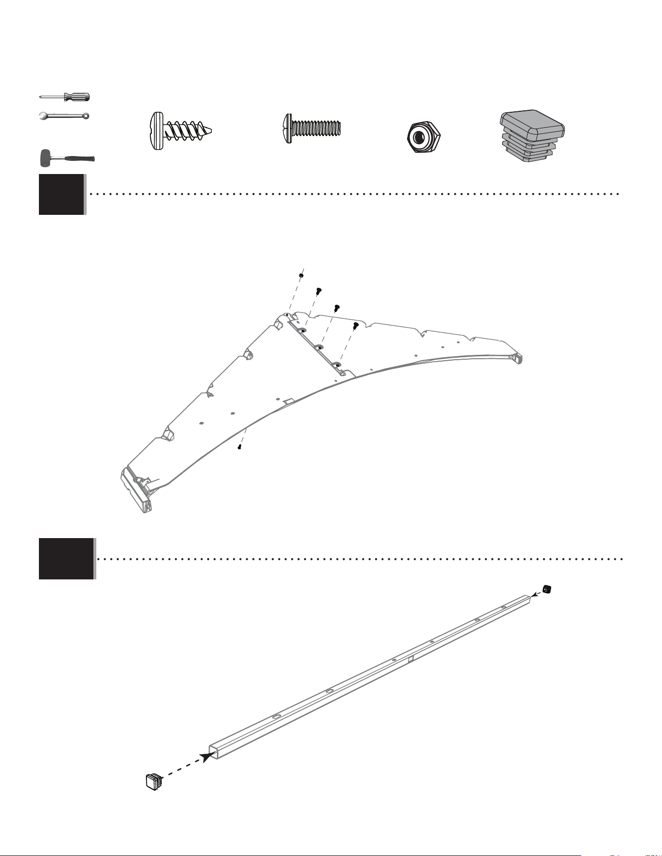
DSP
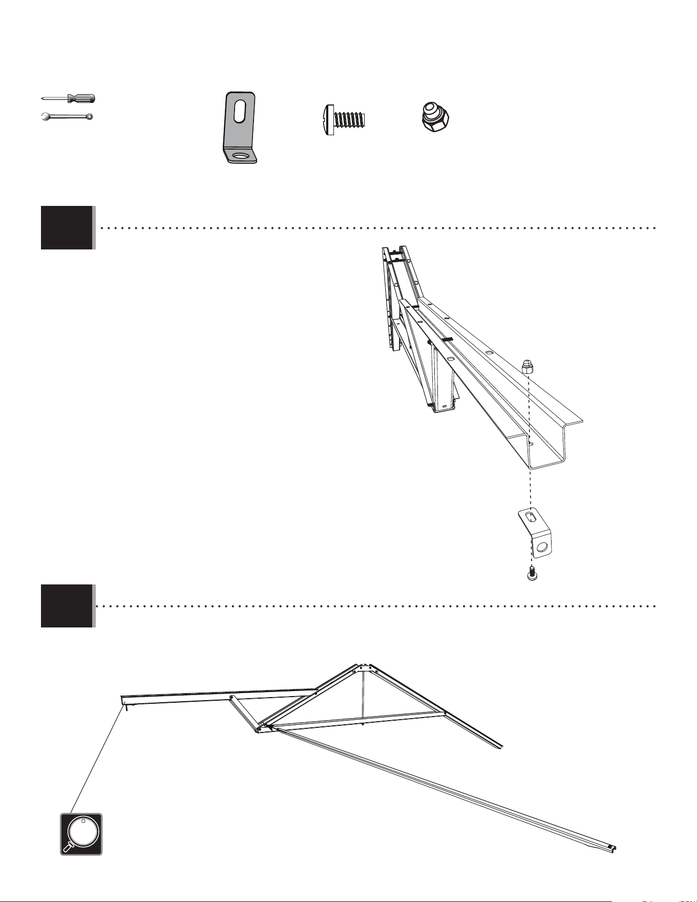
• Only tighten the nut (ADK) by hand in this step.
• Ne serrer l’écrou (ADK) qu’à la main dans cette étape.
• Apretar la tuerca (ADK) sólo à mano en este paso.
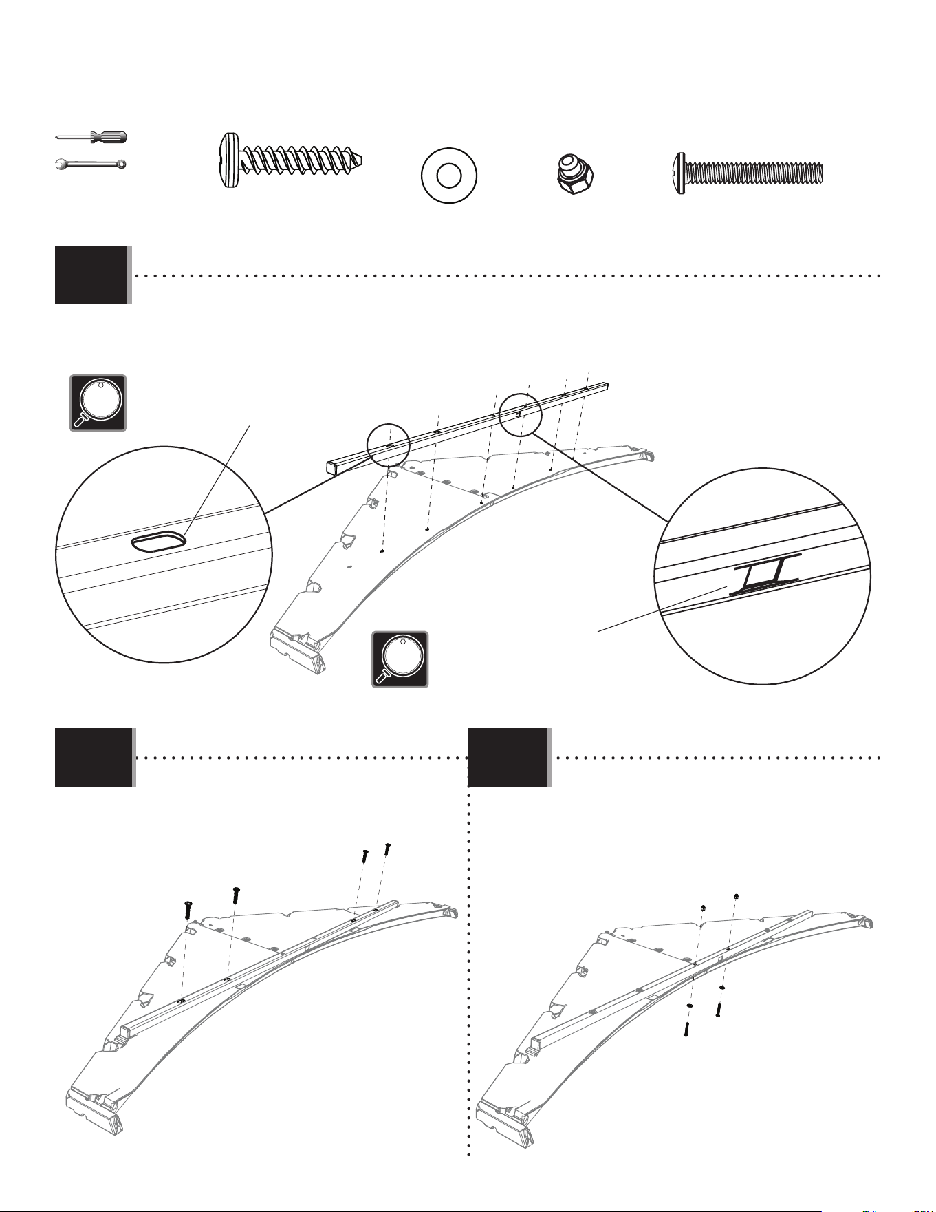
• Slide the support tube (DSP) through the hole in the front truss channel and center it.
• Faire glisser le tube de support (DSP) à travers le trou dans le canal de gouttière avant et le centrer.
• Deslizar le tubo de soporte (DSP) a través del agujero en el canalón de la cercha delantero y céntrarlo.
ADY
ADK
AHT
ADY (x1)
ADK (x1)
AHT (x1)
3/8 in/po
(≈10 mm) (x2)
• This end will face the front of the shed.
• Cette extrémité fera face à la partie avant de l’abri.
• Este extremo dará a la parte delantera de la caseta.
2.14
2.15
2424
GABLE ASSEMBLY / ASSEMBLAGE DES PIGNONS / ENSAMBLAJE DE LAS FACHADAS
3
FTW (x1)
AFE (x2)
ADV (x16)
AHS (x6)
ADW (x10)
AEE (x12)
ENH (x2)
AIQ (x2)
ADZ (x12)*
GHN
Metal part / Pièces en métal / Piezas de metal
Plastic parts / Pièces en plastique / Piezas de plástico
PARTS REQUIRED / PIÈCES REQUISES / PIEZAS REQUERIDAS
HARDWARE REQUIRED / QUINCAILLERIE REQUISE / HERRAJE REQUERIDO
ADK (x2)
EYR (x2)
EYQ (x1)
CXK (x1)
FTM(x1)
FTN (x1)
AGH (x2)
AGI (x2)
TOOLS REQUIRED / OUTILS REQUIS / INSTRUMENTAL REQUERIDO
(Not included—unless otherwise indicated*) / (Non inclus — sauf indication contraire*) / (No incluido, salvo indicación contraria*)
* Not all hardware will be used in the section.
* La quincaillerie n’est pas utilisée au complet dans la section.
* No se utilizará todo el herraje en la sección.
Parts / Pièces / Piezas
3/8"
(≈10 mm)
59 1/2 in/po (≈1,51 m)
59 1/2 in/po (≈151 cm)
46 in/po (≈1,17 m)
46 in/po (≈117 cm)
25
TOOLS AND HARDWARE REQUIRED / OUTILS ET QUINCAILLERIE REQUIS / INSTRUMENTAL Y HERRAJE REQUERIDOS
X SECTION 3 (CONTINUED) / SECTION 3 (SUITE) / SECCIÓN 3 (CONTINUACIÓN)
ADZ (x4)
AGH
AGI
ADZ
ADZ
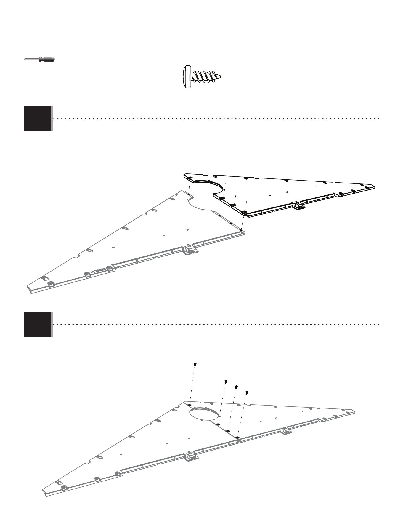
• Align the holes in the side gable halves (AGH and AGI).
• Aligner les trous dans les pignons latéraux (AGH et AGI).
• Alinear los agujeros en las fachadas laterales (AGH y AGI).
• Secure the two gable halves with four (4) screws (ADZ).
• Attacher l’un à l’autre à l’aide de quatre (4) vis (ADZ).
• Sujetar el uno al otro usando cuatro (4) tornillos (ADZ).
3.1
3.2
ADZ
ADZ
26
TOOLS AND HARDWARE REQUIRED / OUTILS ET QUINCAILLERIE REQUIS / INSTRUMENTAL Y HERRAJE REQUERIDOS
X SECTION 3 (CONTINUED) / SECTION 3 (SUITE) / SECCIÓN 3 (CONTINUACIÓN)
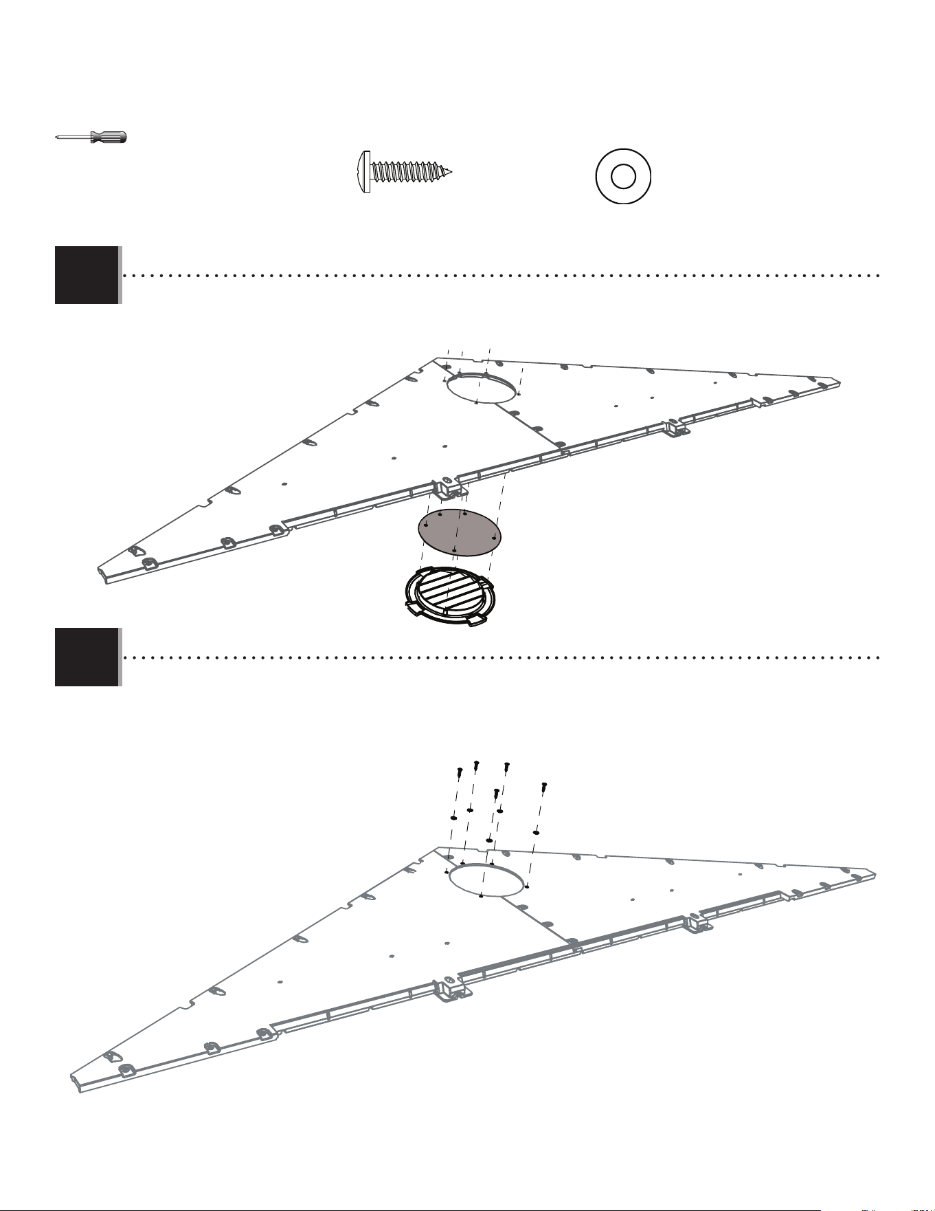
AIQ
ENH
• Place the screen (AIQ) over the vent (ENH) and align the fi ve holes in the vent with those in the gable.
• Mettre la moustiquaire (AIQ) sur l’évent (ENH), et aligner les cinq trous dans l’évent avec ceux du pignon.
• Colocar el mosquitero (AIQ) sobre la rejilla de ventilación (ENH) y alinear los agujeros en la rejilla con los de la fachada.
3.3
ADW (x5)
AEE (x5)
• Secure with the hardware provided.
• Fixer les uns aux autres en utilisant la quincaillerie incluse.
• Fijar los unos a los otros usando el herraje incluido.
3.4
ADW (x5)
AEE (x5)
27
TOOLS AND HARDWARE REQUIRED / OUTILS ET QUINCAILLERIE REQUIS / INSTRUMENTAL Y HERRAJE REQUERIDOS
X SECTION 3 (CONTINUED) / SECTION 3 (SUITE) / SECCIÓN 3 (CONTINUACIÓN)
AHS (x2)
3.5
3.6
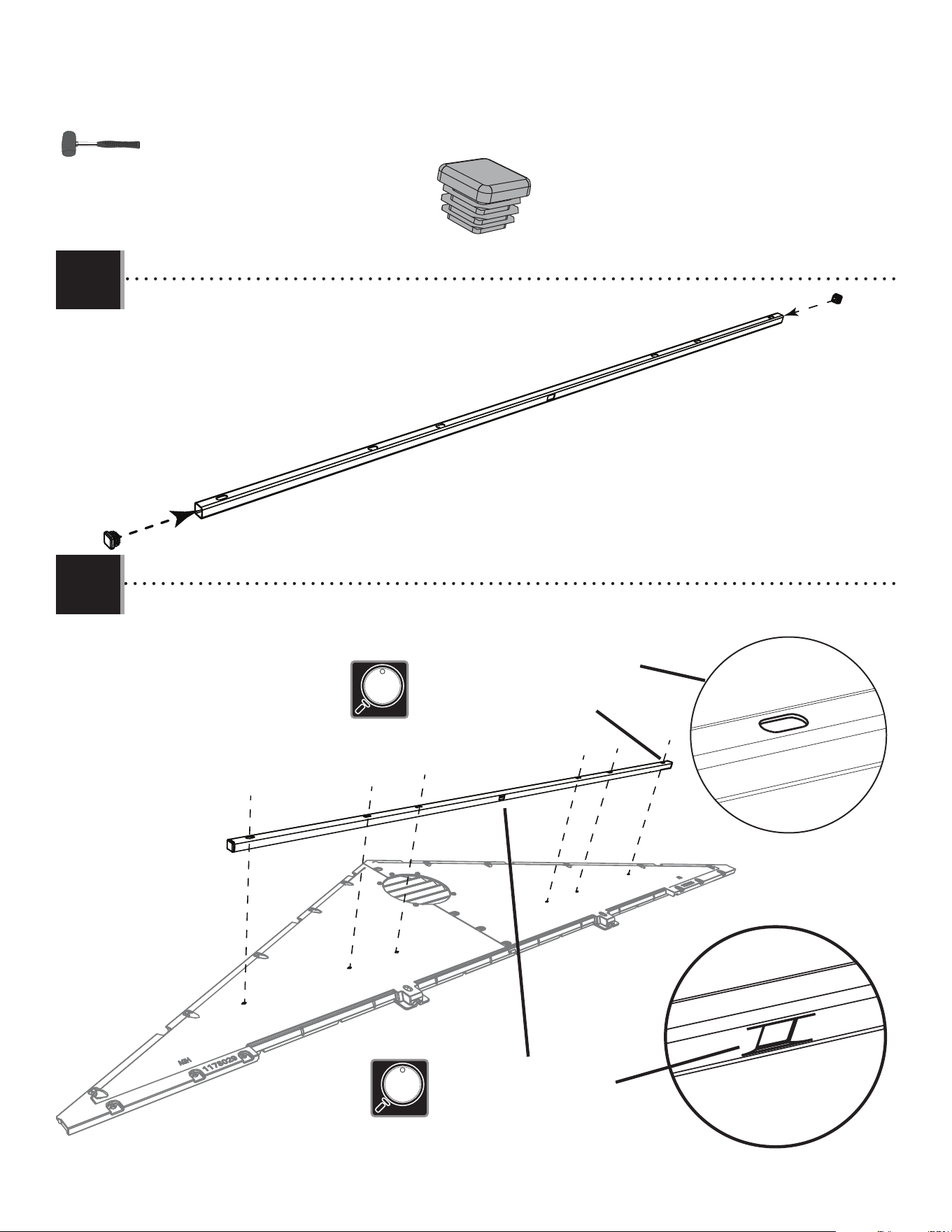
• Insert an end cap (AHS) into each end of the square tube (AFE).
• Insérer un caphuchon (AHS) dans chaque extrémité de tube carré (AFE).
• Insertar un tapon (AHS) en cada extremo del tubo cuadrado (AFE).
AHS
AHS
AFE
• Align the holes in the tube with those in the gable.
• Aligner les trous dans le tube avec ceux du pignon.
• Alinear los agujeros en el tubo con ellos en la fachada.
• The dented hole faces downward.
• Orienter le trou fendu vers le bas.
• Orientar el agujero abollado hacia abajo.
• The fl at holes face away from the gable.
• Les trous plats doivent être face à l’écart du pignon.
• Los agujeros planos dan hacia afuera.
28
TOOLS AND HARDWARE REQUIRED / OUTILS ET QUINCAILLERIE REQUIS / INSTRUMENTAL Y HERRAJE REQUERIDOS
X SECTION 3 (CONTINUED) / SECTION 3 (SUITE) / SECCIÓN 3 (CONTINUACIÓN)
3.7
• Secure with the hardware provided. Repeat the previous steps for the second side gable.
• Fixer les uns aux autres en utilisant la quincaillerie incluse. Répéter les étapes précédentes pour le deuxième pignon latéral.
• Fijar los unos a los otros usando el herraje incluido. Repetir los pasos anteriores para la segunda fachada lateral.
ADV
ADV
ADV
ADV
ADV
ADV
3.8
FTN
FTM
• Align the holes in the left (FTM) and right (FTN) rear gable halves.
• Aligner les trous dans les pignons gauche (FTM) et droite (FTN).
• Alinear los agujeros en las fachadas traseras izquierda (FTM) y derecha (FTN).
ADW (x5)
AEE (x5)
ADV (x6)
ADZ (x4)
AHS (x2)
29
TOOLS AND HARDWARE REQUIRED / OUTILS ET QUINCAILLERIE REQUIS / INSTRUMENTAL Y HERRAJE REQUERIDOS
X SECTION 3 (CONTINUED) / SECTION 3 (SUITE) / SECCIÓN 3 (CONTINUACIÓN)
3.10
3.9
• Secure the two gable halves with three (3) screws (ADZ) and one screw (EYQ) and nut (CXK).
• Attacher l’un à l’autre à l’aide de trois (3) vis (ADZ) et une vis (EYQ) et une écrou (CXK).
• Sujetar el uno al otro usando tres (3) tornillos (ADZ) y un tornillo (EYQ) y una tuerca (CXK).
EYQ
ADZ
ADZ
ADZ
CXK
AHS
AHS
FTW
• Insert an end cap (AHS) into each end of the header (FTW).
• Insérer un capuchon (AHS) dans chaque extrémité du linteau (FTW).
• Insertar un tapón (AHS) en los dos extremos del dintel (FTW).
AHS (x2)
EYQ (x1)
CXK (x1)
ADZ (x3)
3/8"
(≈10 mm)
30
TOOLS AND HARDWARE REQUIRED / OUTILS ET QUINCAILLERIE REQUIS / INSTRUMENTAL Y HERRAJE REQUERIDOS
X SECTION 3 (CONTINUED) / SECTION 3 (SUITE) / SECCIÓN 3 (CONTINUACIÓN)
3.11
• Secure with four screws (ADV).
• Fixer avec quatre vis (ADV).
• Fijar con cuatro tornillos (ADV).
• Secure with two screws (EYR), two washers (AEE), and
two nuts (ADK).
• Fixer avec deux vis (EYR), deux rondelles (AEE), et
deux écrous (ADK).
• Fijar con dos tornillos (EYR), dos rondanas (AEE), y dos
tuercas (ADK).
• Align the holes in the header with those in the entry gable.
• Aligner les trous dans le linteau avec ceux du pignon d’entrée.
• Alinear los agujeros en el dintel con ellos en la fachada de entrada.
ADV
ADV
• The fl at holes face away from the gable.
• Les trous plats doivent être face à l’écart du pignon.
• Los agujeros planos dan hacia afuera.
• The dented hole faces downward.
• Orienter le trou fendu vers le bas.
• Orientar el agujero abollado hacia abajo.
3.12
3.13
ADV (x4)
AEE (x2)
ADK (x2)
EYR (x2)
AEE
AEE
EYR
EYR
ADK
ADK
3/8"
(≈10 mm)
3131
LEFT DOOR ASSEMBLY / ASSEMBLAGE DE LA PORTE GAUCHE / ENSAMBLE DE LA PUERTA IZQUIERDA
4
BDJ (x1)
EDW (x1)
Metal parts / Pièces en métal / Piezas de metal
Plastic parts / Pièces en plastique / Piezas de plástico
PARTS REQUIRED / PIÈCES REQUISES / PIEZAS REQUERIDAS
HARDWARE REQUIRED / QUINCAILLERIE REQUISE / HERRAJE REQUERIDO
CRE (x1)
BYR (x1)
BYS (x1)
ADW (x1)
BBH (x1)
BYZ (x2)
AEE (x3)
HKO
DHL
ARA (x1) 1/8 in/po (≈3 mm)
AEB (x2)
ENO (x4)
ACH (x2)
AAB (x2)
EOY (x1)
DGR (x1)
DGS (x1)
ENP (x2)
Upper / Supérieur / Superior
Lower / Inférieur / Inferior
ADZ (x14)
EPH (x1)
DHN (x1)
TOOLS REQUIRED / OUTILS REQUIS / INSTRUMENTAL REQUERIDO
(Not included—unless otherwise indicated*) / (Non inclus — sauf indication contraire*) / (No incluido, salvo indicación contratia*)
ARA (x1) 1/8 in/po (≈3 mm)*
Top End / Extrémité supérieure / Extremo superior
74 1/2 in/po (≈1,89 m)
74 1/2 in/po (≈189 cm)
32
TOOLS AND HARDWARE REQUIRED / OUTILS ET QUINCAILLERIE REQUIS / INSTRUMENTAL Y HERRAJE REQUERIDOS
X SECTION 4 (CONTINUED) / SECTION 4 (SUITE) / SECCIÓN 4 (CONTINUACIÓN)
BBH (x1)
EDW
BDJ
• Align these holes in the next step
• Aligner ces trous à l’étape suivante
• Alinear estos agujeros en el paso siguiente
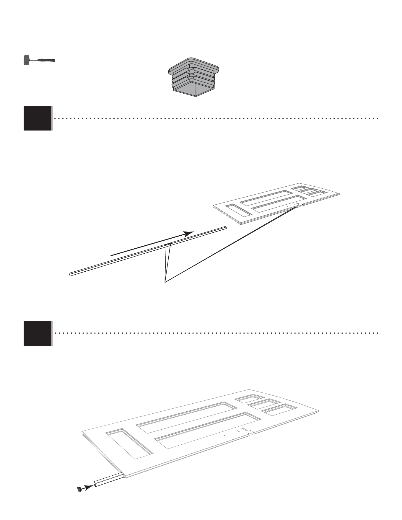
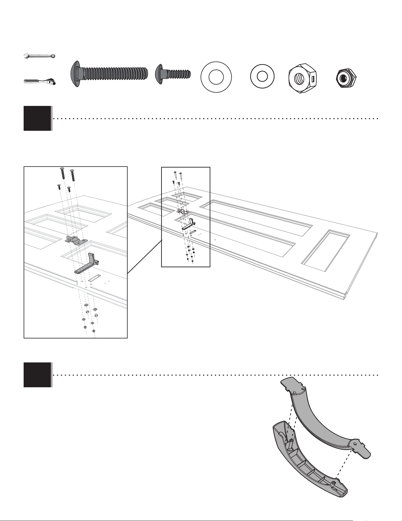
• Insert an end cap (BBH) into the end of the tube, and fi nish inserting the tube until fl ush with bottom of door and the
two holes in the tube align with those in the door.
• Insérer un capuchon (BBH) dans l’extrémité du tube, et continuer à insérer le tube jusqu’à ce qu’il soit à ras au bord
inférieur de la porte et les deux trous dans le tube s’alignent avec ceux dans la porte.
• Insertar un tapon (BBH) adentro del extremo del tubo, y seguir con la inserción del tubo hasta que esté al ras del
borde inferior de la puerta y los dos agujeros en el tubo se alineen con ellos en la puerta.
BBH
4.2
4.1
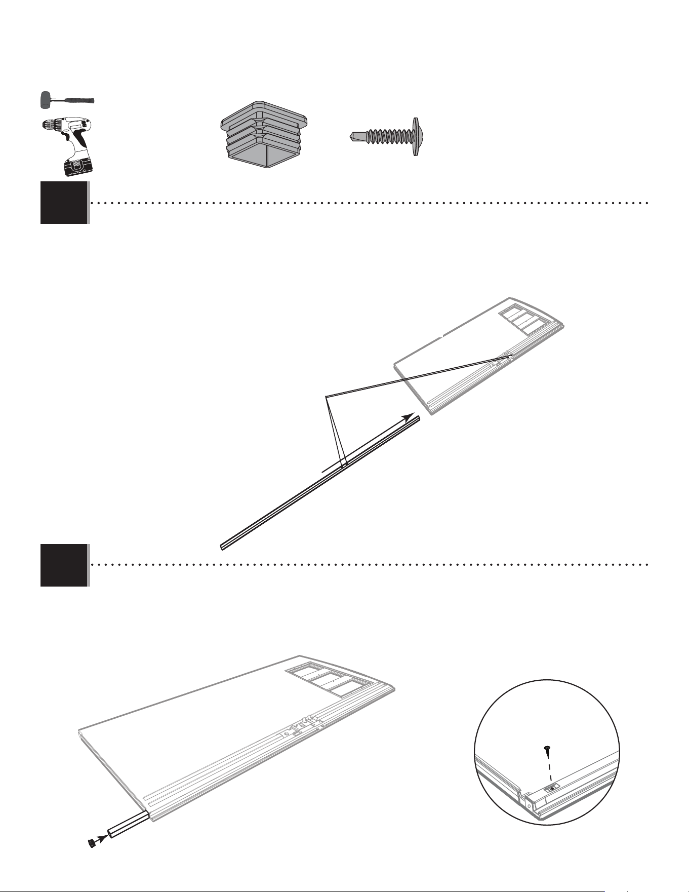
• Slide a long tube (EDW) into the hole in the left door (BDJ) until a few inches remain out of the door. The end with the hole goes at the
top.
• Faire glisser le tube grand (EDW) à travers le trou de la porte gauche (BDJ) jusqu’à ce qu’il dépasse quelques pouces de la
porte. L’extrémité avec le trou va vers le haut.
• Deslizar el tubo largo (EDW) adentro del agujero en la puerta izquierda (BDJ) hasta que el tubo cuelgue unas pulgadas de la
puerta. El extremo con el agujero va al tope.
33
TOOLS AND HARDWARE REQUIRED / OUTILS ET QUINCAILLERIE REQUIS / INSTRUMENTAL Y HERRAJE REQUERIDOS
X SECTION 4 (CONTINUED) / SECTION 4 (SUITE) / SECCIÓN 4 (CONTINUACIÓN)
4.3
4.4
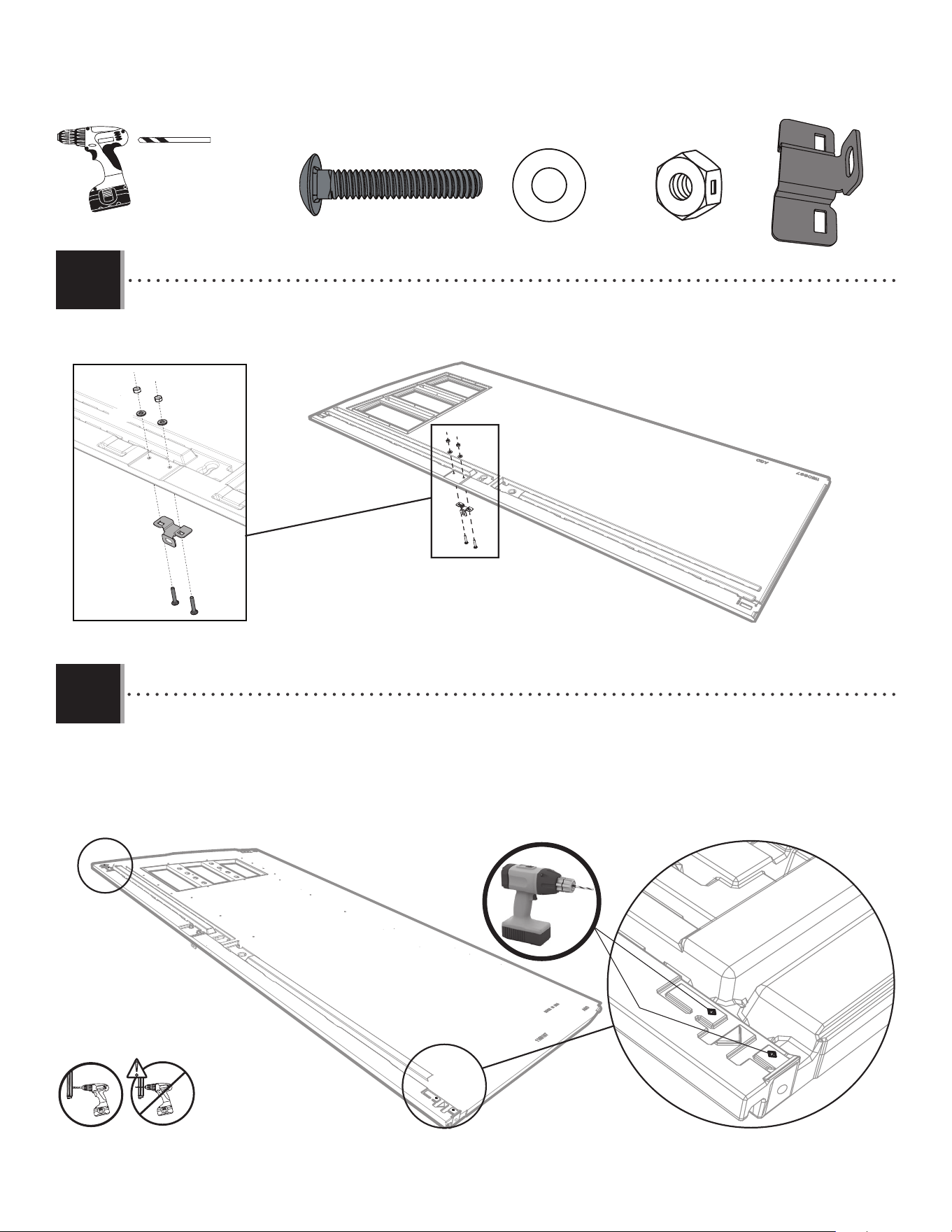
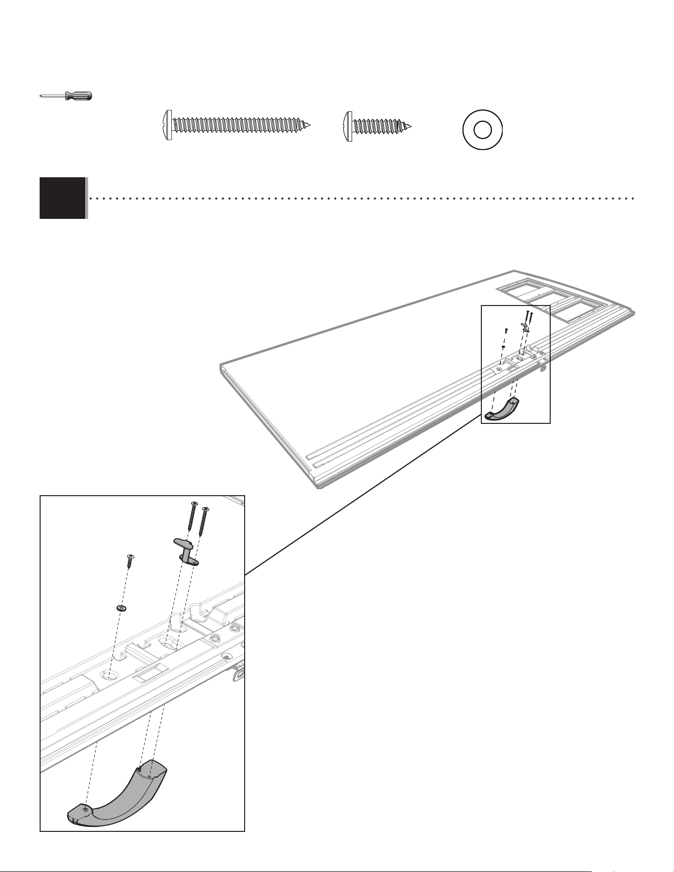
• Attach the left latch bracket (EOY) to the door using the hardware included. Tighten only by hand at this point.
• Attacher le support gauche à loquet (EOY) à la porte à l’aide de la quincaillerie incluse. Serrer-les à la main seulement en ce moment.
• Sujetar el soporte izquierdo para el pestaño (EOY) a la puerta usando el herraje incluido. Apretarlos sólo a mano en este momento.
AAB (x2)
AAB
AAB
ACH (x2)
ACH
ACH
AEB (x2)
AEB
AEB
EOY (x1)
EOY
• Drill into the divots at the top and bottom of the door and into the tube inside but not all the way through the door.
Use the 1/8" (≈3 mm) drill bit (ARA) included.
• Percer les marques à la partie supérieure et inférieure de la porte et dedans le tube à l’intéreiur mais pas à travers
la porte entière. Utiliser le Foret de ≈3 mm (1/8 po) (ARA) inclus.
• Taladrar las marcas al tope y al fondo de la puerta y dentro del tubo adentro mas no por la puerta entera. Usar la
broca de ≈3 mm (1/8 in.) (ARA) incluida.
!
1/8 in/po
(≈3 mm)
ARA (x1)
34
TOOLS AND HARDWARE REQUIRED / OUTILS ET QUINCAILLERIE REQUIS / INSTRUMENTAL Y HERRAJE REQUERIDOS
X SECTION 4 (CONTINUED) / SECTION 4 (SUITE) / SECCIÓN 4 (CONTINUACIÓN)
4.5
4.6
BYS
BYR
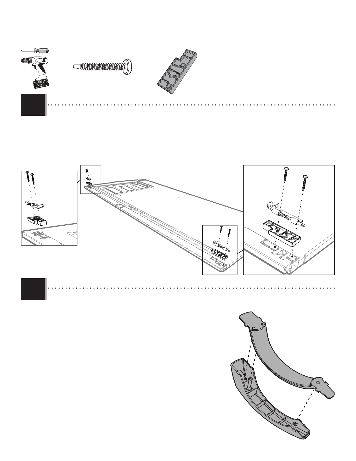
• Attach the two handle pieces (BYR & BYS) together as shown.
• Joindre les deux pièces de la poignée (BYR et BYS) comme illustré.
• Conectar las dos piezas del picaporte (BYR y BYS) como se muestra.
• Attach the locks (DGS & DGR) and spacers (ENP) to the top and bottom of the left door. If the pins in the locks do not move freely, loosen the
screws (ENO) just a tad.
• Attacher les verrous (DGS et DGR) et les pièces d’écartement (ENP) à la partie supérieure et inférieure à la porte gauche. Si les
verrous ne se déplacent pas librement, deserrer les vis (ENO) un pétit peu.
• Sujetar los pasadores (DGS y DGR) y los espaciadores (ENP) al tope y al fondo de la puerta izquierda. Si los pasadores no se mueven
libremente, afl ojar los tornillos (ENP) un poquito.
ENP (x2)
ENO (x4)
DGR
ENO
ENO
ENO
DGS
ENP
ENP
35
TOOLS AND HARDWARE REQUIRED / OUTILS ET QUINCAILLERIE REQUIS / INSTRUMENTAL Y HERRAJE REQUERIDOS
X SECTION 4 (CONTINUED) / SECTION 4 (SUITE) / SECCIÓN 4 (CONTINUACIÓN)
CRE
4.7
4.8
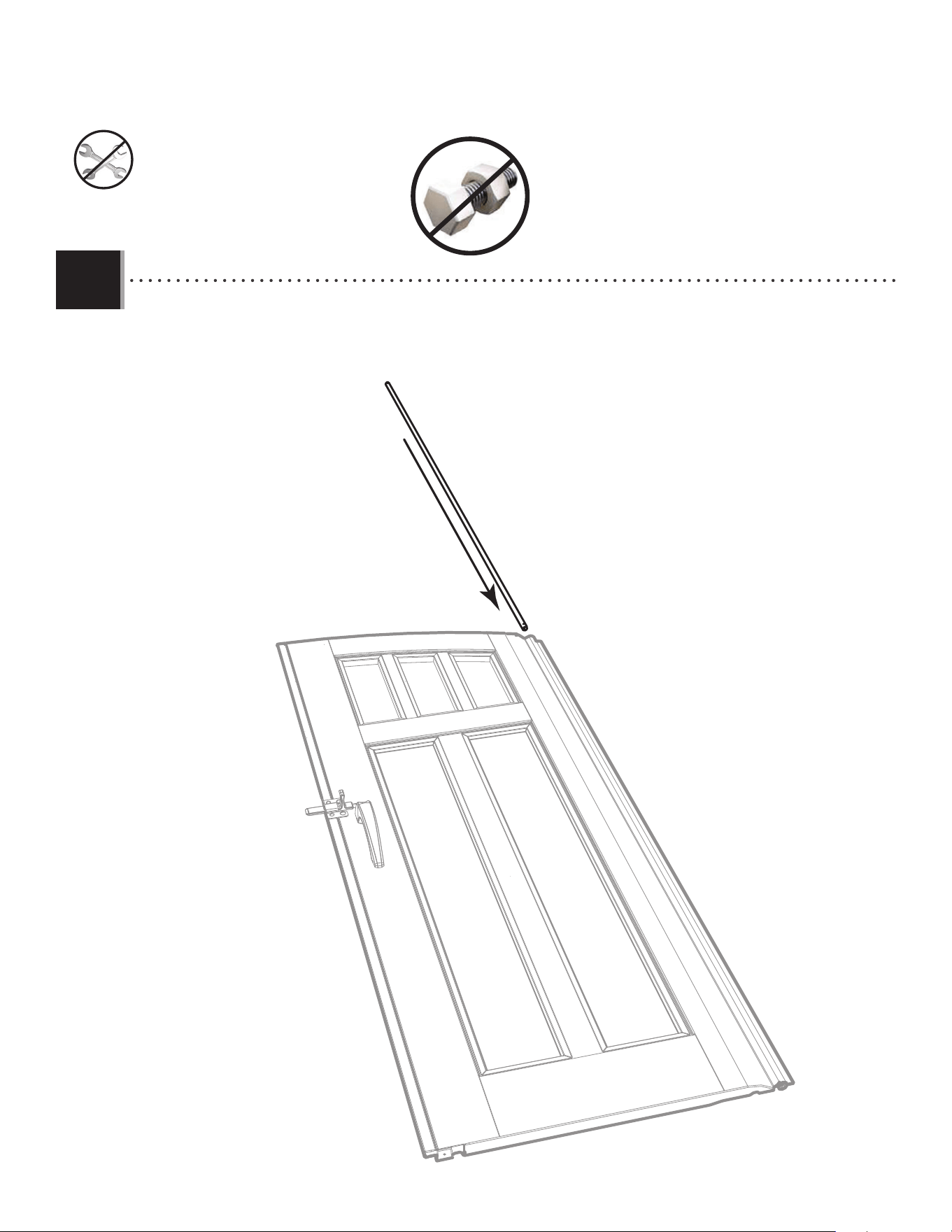
• Slide a hinge tube (CRE) into the hole in the door until a
few inches remain out of the bottom.
• Faire glisser le tube de charnière (CRE) à travers le trou de
la porte jusqu’à ce qu’il dépasse quelques pouces
de la partie inférieure de la porte.
• Deslizar un tubo de bisagra (CRE) adentro del agujero en
la puerta hasta que el tubo cuelgue unas pulgadas
de la parte inferior de la puerta.
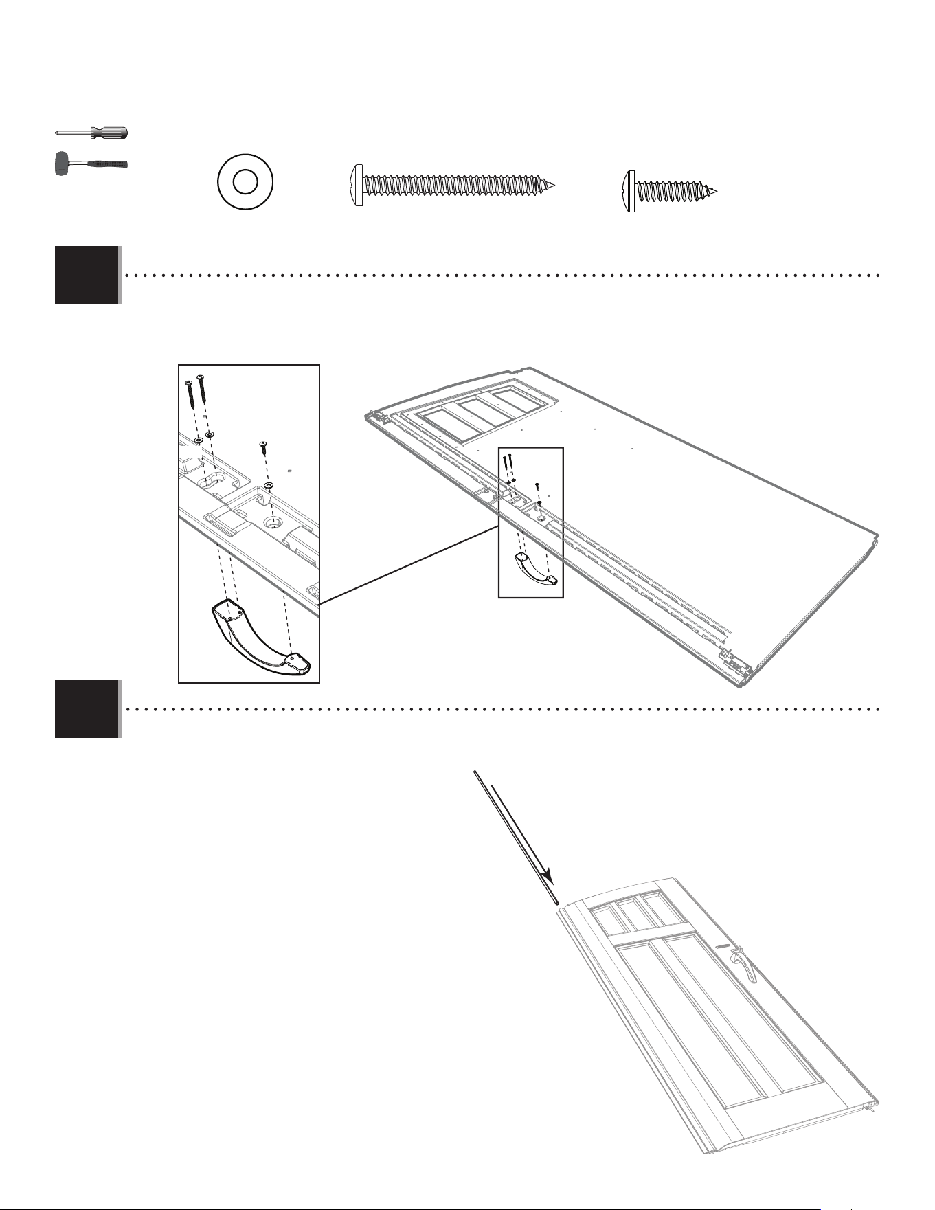
• Secure the handle to the door using the hardware included.
• Fixer la poignée à la porte à l’aide de la quincaillerie incluse.
• Fijar el picoporte a la puerta usando el herraje incluido.
ADW (x1)
ADW
BYZ (x2)
BYZ (x2)
AEE (x3)
AEE
AEE
AEE
36
TOOLS AND HARDWARE REQUIRED / OUTILS ET QUINCAILLERIE REQUIS / INSTRUMENTAL Y HERRAJE REQUERIDOS
X SECTION 4 (CONTINUED) / SECTION 4 (SUITE) / SECCIÓN 4 (CONTINUACIÓN)
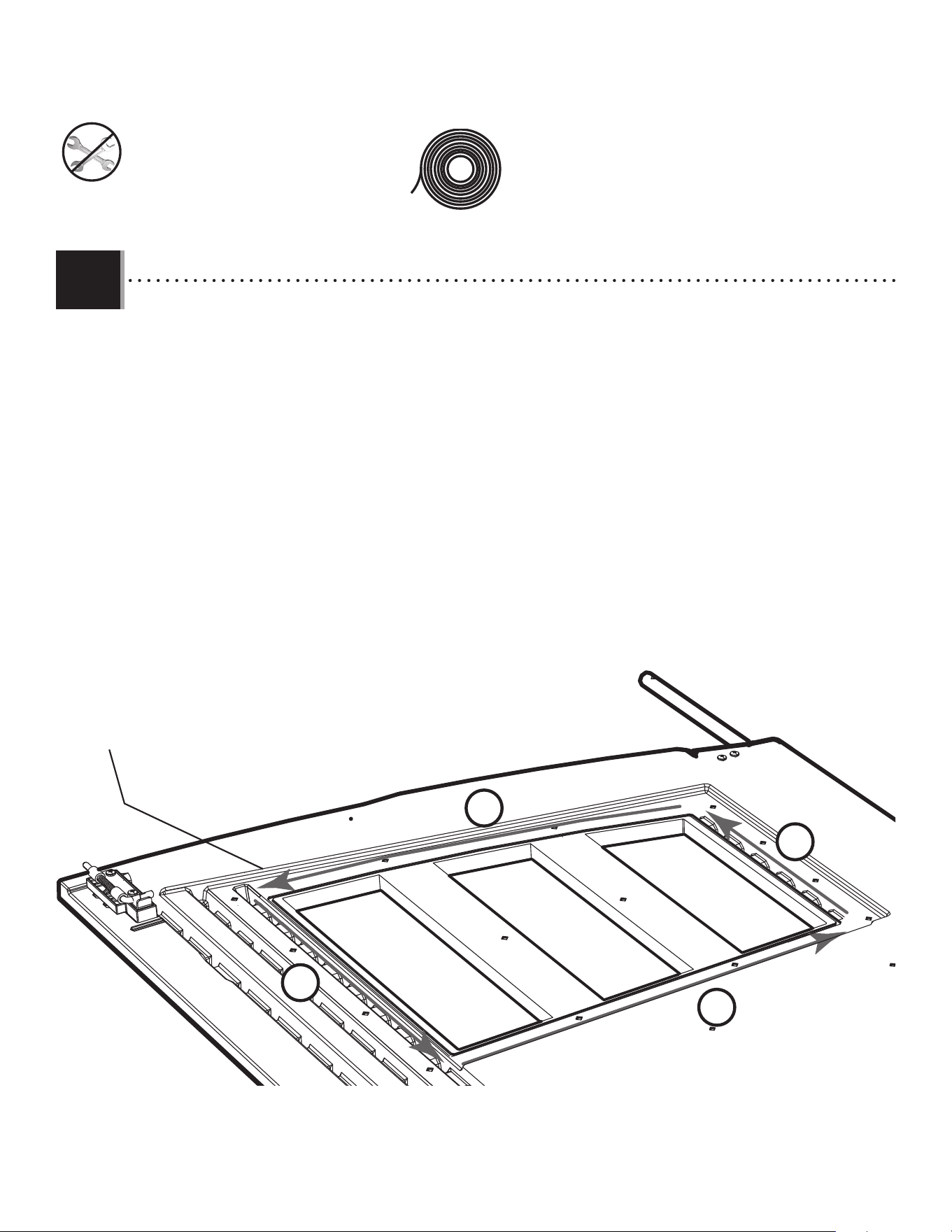
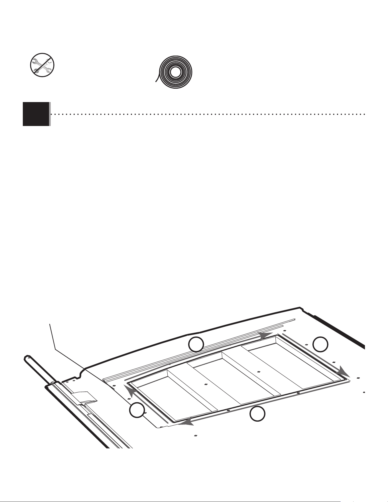
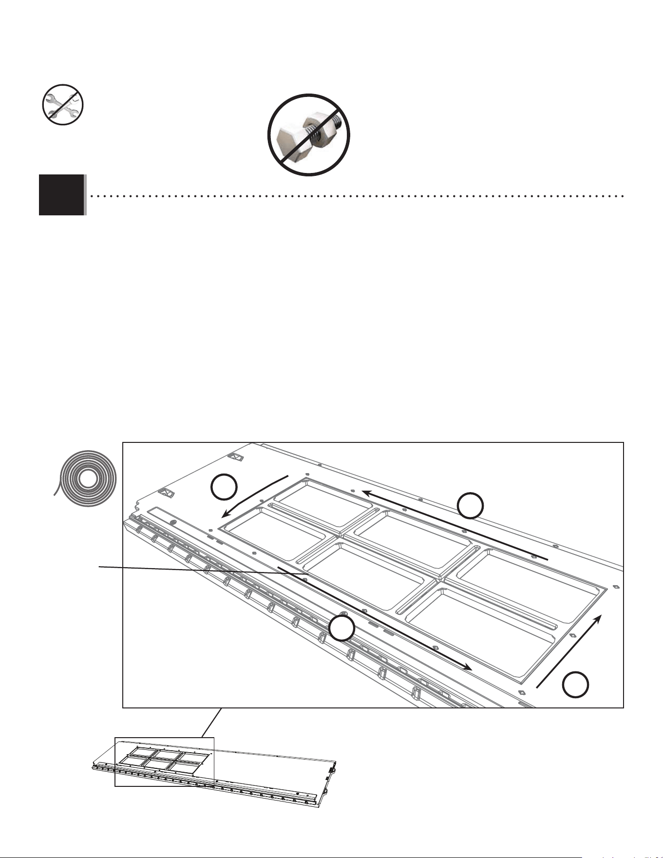
• There is a narrow groove (illustrated in black) running along the outside of the window on the back of each door.
Starting at the top, left corner of the groove in the left door, lay the 1/8" (≈3 mm) strip of butyl tape (EPH) into the groove.
Do not worry about getting the tape completely into the groove just yet—simply lay the tape over the groove. Do not press the tape into the groove. Do not stretch the
tape. Work your way downward (1) and, as you get to each corner, peel o the paper backing from the tape you just
laid (peel o backing at each corner). Go along the bottom (2) of the window. Curve your way upward (3) and then
along the top (4) of the window until you’re back where you started. Clip o the excess.
• Une rainure étroite (illustrée en noir) se trouve le long de l’extérieur de la fenêtre à l’arrière de chaque porte. Partant
du coin supérieur gauche de la rainure de la porte gauche, étendre une goutte de 1/8 po (3 mm) de ruban butylique
(EPH) dans la rainure. Ne pas s’inquiéter si la goutte n’est pas complètement dans la rainure en ce moment, ne faire que déposer la goutte sur la rainure. Ne pas
pousser la goutte dans la rainure. Ne pas étirer le goutte. Travailler vers le bas (1) et, en approchant chaque courbe, retirer le papier
protecteur du ruban récemment étendé (retirer le papier protecteur a chaque courbe). Étendre le ruban le long du
bas (2) de la fenêtre. Courber vers le haut (3), puis le long du haut (4) de la fenêtre jusqu’à revenir au point de départ.
Couper l’excédent.
• Hay una ranura angosta (ilustrada en negro) bordeando la ventana en la superfi cie posterior de cada puerta.
Comenzando desde arriba, en la esquina izquierda de la ranura en la puerta izquierda, aplicar una línea de 3 mm
(1/8 in) de cinta butílica (EPH) en de la ranura. Ne preocuparse por poner la cinta, mas solamente poner la cinta sobre la ranura. No presionar la cinta dentro
de la ranura. No estirar la línea. Seguir hacia abajo (1) y, al acercar cada ángulo, quitar el papel protector de la cinta recién
aplicada (quitar el papel protector a cada ángulo). Seguir a lo largo del borde inferior (2) de la ventana. Curvearla
hacia arriba (3) y, entonces, a lo largo del borde superior (4) de la ventana hasta estar al punto de partida. Cortar el exceso.
Groove / Rainure / Ranura
EPH (x1)
1
2
3
4
4.9
37
TOOLS AND HARDWARE REQUIRED / OUTILS ET QUINCAILLERIE REQUIS / INSTRUMENTAL Y HERRAJE REQUERIDOS
X SECTION 4 (CONTINUED) / SECTION 4 (SUITE) / SECCIÓN 4 (CONTINUACIÓN)
ADZ (x14)
DHN
ADZ
ADZ
ADZ
ADZ
ADZ
ADZ
ADZ
ADZ
ADZ
ADZ
ADZ
ADZ
ADZ
ADZ
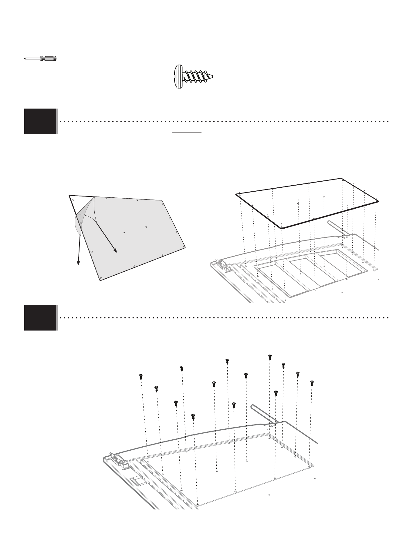
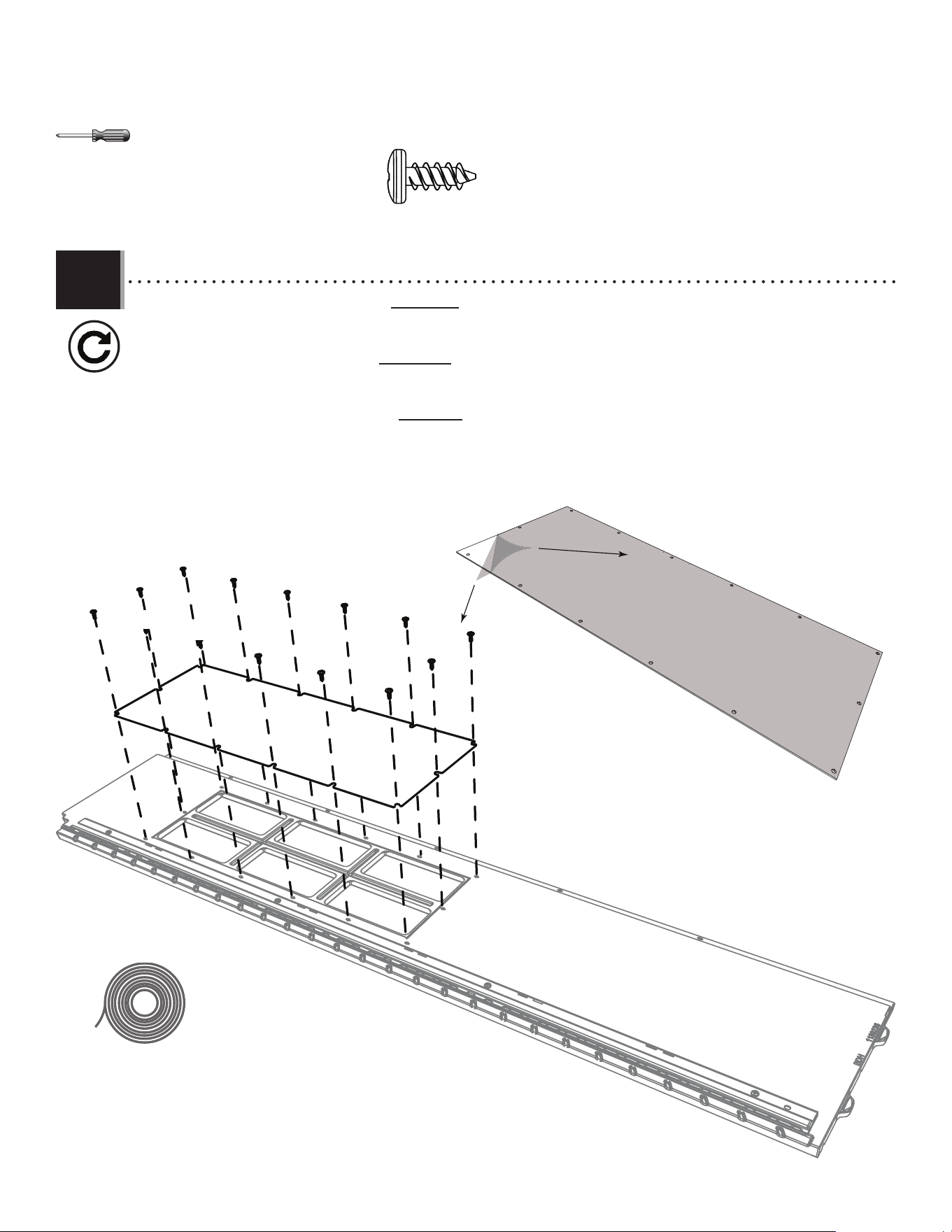
• Peel o the protective backing from both sides of window pane (DHN). Align the holes in the pane with those in the
door, and gently set a window pane (DHN) down onto the door.
• Retirer la pellicule protectrice des deux côtés du carreau (DHN). Aligner les trous dans le carreau avec ceux de la
porte, et mettre le carreau (DHN) sur la porte.
• Retirar el protector de plástico de las dos caras de una hoja (DHN). Alinear los agujeros en la hoja con los de la
puerta, y colocar ligeramente la hoja de ventana (DHN) en la puerta.
• Secure the pane to the door using fourteen (14) screws (ADZ).
• Fixer le carreau à la porte en utilisant quatorze (14) vis (ADZ).
• Fijar la hoja a la puerta usando catorce (14) tornillos (ADZ).
4.10
4.11
DHN
3838
RIGHT DOOR ASSEMBLY / ASSEMBLAGE DE LA PORTE DROITE / ENSAMBLE DE LA PUERTA DERECHA
5
EWI
HARDWARE REQUIRED / QUINCAILLERIE REQUISE / HERRAJE REQUERIDO
Metal Parts / Pièces en métal / Piezas de metal
PARTS REQUIRED / PIÈCES REQUISES / PIEZAS REQUERIDAS
7/16 in/po (≈11 mm) 3/8 in/po (≈10 mm)
BDK (x1)
Plastic Parts / Pièces en plastique / Piezas de plástico
EDW (x1)
CRE (x1)
DHN (x1)
ADW (x1)
BYZ (x2)
BYS (x1)
BYR (x1)
EOZ (x1)
EPA (x1)
AAB (x2)
ACH (x2)
AEB (x2)
CXK (x2)
EPC (x2)
AEE (x3)
CHK (x1)
BBI (x1)
BBH (x1)
DHL
ADZ (x14)
EPH (x1)
TOOLS REQUIRED / OUTILS REQUIS / INSTRUMENTAL REQUERIDO
(Not included—unless otherwise indicated*) / (Non inclus — sauf indication contraire*) / (No incluido, salvo indicación contratia*)
Parts / Pièces / Piezas
Top End / Extrémité supérieure / Extremo superior
74 1/2 in/po (≈1,89 m)
74 1/2 in/po (≈189 cm)
39
TOOLS AND HARDWARE REQUIRED / OUTILS ET QUINCAILLERIE REQUIS / INSTRUMENTAL Y HERRAJE REQUERIDOS
X SECTION 5 (CONTINUED) / SECTION 5 (SUITE) / SECCIÓN 5 (CONTINUACIÓN)
BBH (x1)
EDW
BDK
• Slide a long tube (EDW) into the hole in the right door (BDK) until a few inches remain out of the door. The end with the hole goes at
the top.
• Faire glisser le tube grand (EDW) à travers le trou de la porte droite (BDK) jusqu’à ce qu’il dépasse quelques pouces de la
porte. L’extrémité avec le trou va vers le haut.
• Deslizar el tubo largo (EDW) adentro del agujero en la puerta derecha (BDK) hasta que el tubo cuelgue unas pulgadas de la
puerta. El extremo con el agujero va al tope.
BHH
• Align these holes in the next step
• Aligner ces trous à l’étape suivante
Alinear estos agujeros en el paso siguiente
5.2
5.1
• Insert an end cap (BBH) into the end of the tube and fi nish inserting the tube until fl ush with bottom of door. Then, use
a drill to insert a self-drilling screw (CHK) to hold it in place.
• Insérer un capuchon (BBH) dans l’extrémité du tube et terminer d’insérer le tube jusqu’à ce qu’il soit égal au bas de la
porte. Puis, utiliser une perceuse pour insérer une vis autotaraudeuse (CHK) pour la maintenir en place.
• Insertar un tapon (BBH) en el extremo del tubo y terminar de insertar el tubo hasta se alinee con la parte inferior de la
puerta. Después, usar un taladro eléctrico para insertar un tornillo auto-perforante (CHK) para mantenerlo en su lugar.
CHK
CHK (x1)
40
TOOLS AND HARDWARE REQUIRED / OUTILS ET QUINCAILLERIE REQUIS / INSTRUMENTAL Y HERRAJE REQUERIDOS
X SECTION 5 (CONTINUED) / SECTION 5 (SUITE) / SECCIÓN 5 (CONTINUACIÓN)
• Attach the latch as shown. Ensure the tube inside the door is fl ush with the bottom of the door, then tighten securely.
• Veiller à que le tube dans la porte est à ras du bord inférieur de la porte. Ensuite, bien fi xer le loquet comme
indiqué.
• Asegurarse de que el tubo dentro de la puerta está a ras del borde inferior de la puerta. Entonces, fi jar bien el
pestaño como se muestra.
BYS
BYR
• Attach the two handle pieces (BYR & BYS) together as indicated.
• Attacher les deux pièces de la poignée (BYR et BYS) comme indiqué.
• Conectar las dos piezas del picaporte (BYR y BYS) como se muestra.
7/16 in/po
(≈11 mm)
3/8 in/po
(≈10 mm)
EDA
EPA
AAB (x2)
AAB
AAB
ACH (x2)
ACH
ACH
AEB (x2)
AEE (x2)
CXK (x2)
CXK
CXK
EPC (x2)
EPC
EPC
AEB
AEB
AEE
AEE
5.3
5.4
41
TOOLS AND HARDWARE REQUIRED / OUTILS ET QUINCAILLERIE REQUIS / INSTRUMENTAL Y HERRAJE REQUERIDOS
X SECTION 5 (CONTINUED) / SECTION 5 (SUITE) / SECCIÓN 5 (CONTINUACIÓN)
• Attach the handle as indicated. Tighten securely.
• Bien attacher la poignée comme indiqué. Bien serrer la quincaillerie.
• Sujetar bien el picoporte como se muestra. Apretar bien el herraje.
ADW (x1)
ADW
BYZ (x2)
BYZ
BYZ
AEE (x1)
AEE
BBI
5.5
42
TOOLS AND HARDWARE REQUIRED / OUTILS ET QUINCAILLERIE REQUIS / INSTRUMENTAL Y HERRAJE REQUERIDOS
X SECTION 5 (CONTINUED) / SECTION 5 (SUITE) / SECCIÓN 5 (CONTINUACIÓN)
5.6
• Slide a hinge tube (CRE) into the hole in the door until a few inches remain out of the bottom.
• Faire glisser le tube de charnière (CRE) à travers le trou de la porte jusqu’à ce qu’il dépasse quelques pouces de la partie
inférieure de la porte.
• Deslizar un tubo de bisagra (CRE) adentro del agujero en la puerta hasta que el tubo cuelgue unas pulgadas de la parte
inferior de la puerta.
CRE
43
TOOLS AND HARDWARE REQUIRED / OUTILS ET QUINCAILLERIE REQUIS / INSTRUMENTAL Y HERRAJE REQUERIDOS
X SECTION 5 (CONTINUED) / SECTION 5 (SUITE) / SECCIÓN 5 (CONTINUACIÓN)
5.7
• There is a narrow groove (illustrated in black) running along the outside of the window on the back of each door.
Starting at the top, right corner of the groove in the right door, lay the 1/8" (≈3 mm) strip of butyl tape (EPH) into the
groove. Do not worry about getting the tape completely into the groove just yet—simply lay the tape over the groove. Do not press the tape into the groove.
Do not stretch the tape. Work your way downward (1) and, as you get to each corner, peel o the paper backing from the
tape you just laid (peel o backing at each corner). Go along the bottom (2) of the window. Curve your way upward
(3) and then along the top (4) of the window until you’re back where you started. Clip o the excess.
• Une rainure étroite (illustrée en noir) se trouve le long de l’extérieur de la fenêtre à l’arrière de chaque porte.
Partant du coin supérieur droit de la rainure de la porte droite, étendre une goutte de 1/8 po (3 mm) de ruban
butylique (EPH) dans la rainure. Ne pas s’inquiéter si la goutte n’est pas complètement dans la rainure en ce moment, ne faire que déposer la goutte sur
la rainure. Npas étirer pas le goutte. Ne pas pousser la goutte dans la rainure. Travailler vers le bas (1) et, en approchant
chaque courbe, retirer le papier protecteur du ruban étendé (retirer le papier protecteur a chaque courbe).
Étendre le ruban étendé le long du bord inférieur (2) de la fenêtre. Courber en haut (3), puis le long du haut (4) de la
fenêtre jusqu’à revenir au point de départ. Couper l’excédent.
• Hay una ranura angosta (ilustrada en negro) bordeando la ventana en la superfi cie posterior de cada puerta.
Comenzando desde arriba, en la esquina derecha de la ranura en la puerta derecha, aplicar una línea de 3 mm
(1/8 in) de cinta butílica (EPH) en la ranura. Ne preocuparse por poner la cinta, mas solamente poner la cinta sobre la ranura. No presionar la cinta
dentro de la ranura. No estirar la línea. Seguir hacia abajo (1), y, al acercar cada ángulo, quitar el papel protector de la cinta
recién aplicada (quitar el papel protector a cada ángulo). Seguir a lo largo del borde inferior (2) de la ventana.
Curvearla hacia arriba (3) y, entonces, a lo largo del borde superior (4) de la ventana hasta estar al punto de
partida. Cortar el exceso.
Groove / Rainure / Ranura
EPH (x1)
1
2
3
4
44
TOOLS AND HARDWARE REQUIRED / OUTILS ET QUINCAILLERIE REQUIS / INSTRUMENTAL Y HERRAJE REQUERIDOS
X SECTION 5 (CONTINUED) / SECTION 5 (SUITE) / SECCIÓN 5 (CONTINUACIÓN)
ADZ (x14)
DHN
ADZ
ADZ
ADZ
ADZ
ADZ
ADZ
ADZ
ADZ
ADZ
ADZ
ADZ
ADZ
ADZ
ADZ
• Peel o the protective backing from both sides of window pane (DHN). Align the holes in the pane with those in the door,
and gently set a window pane (DHN) down onto the door.
• Retirer la pellicule protectrice des deux côtés du carreau (DHN). Aligner les trous dans le carreau avec ceux de la
porte, et mettre le carreau (DHN) sur la porte.
• Retirar el protector de plástico de las dos caras de una hoja (DHN). Alinear los agujeros en la hoja con los de la
puerta, y colocar ligeramente la hoja de ventana (DHN) en la puerta.
• Secure the pane to the door using fourteen (14) screws (ADZ).
• Fixer le carreau à la porte en utilisant quatorze (14) vis (ADZ).
• Sujetar la hoja a la puerta usando catorce (14) tornillos (ADZ).
5.8
5.9
DHN
4545
FLOOR ASSEMBLY / ASSEMBLAGE DU PLANCHER / ENSAMBLAJE DEL PISO
6
CUD (x2)
CUW (x2)
Plastic parts / Pièces en plastique / Piezas de plástico
PARTS REQUIRED / PIÈCES REQUISES / PIEZAS REQUERIDAS
HARDWARE REQUIRED / QUINCAILLERIE REQUISE / HERRAJE REQUERIDO
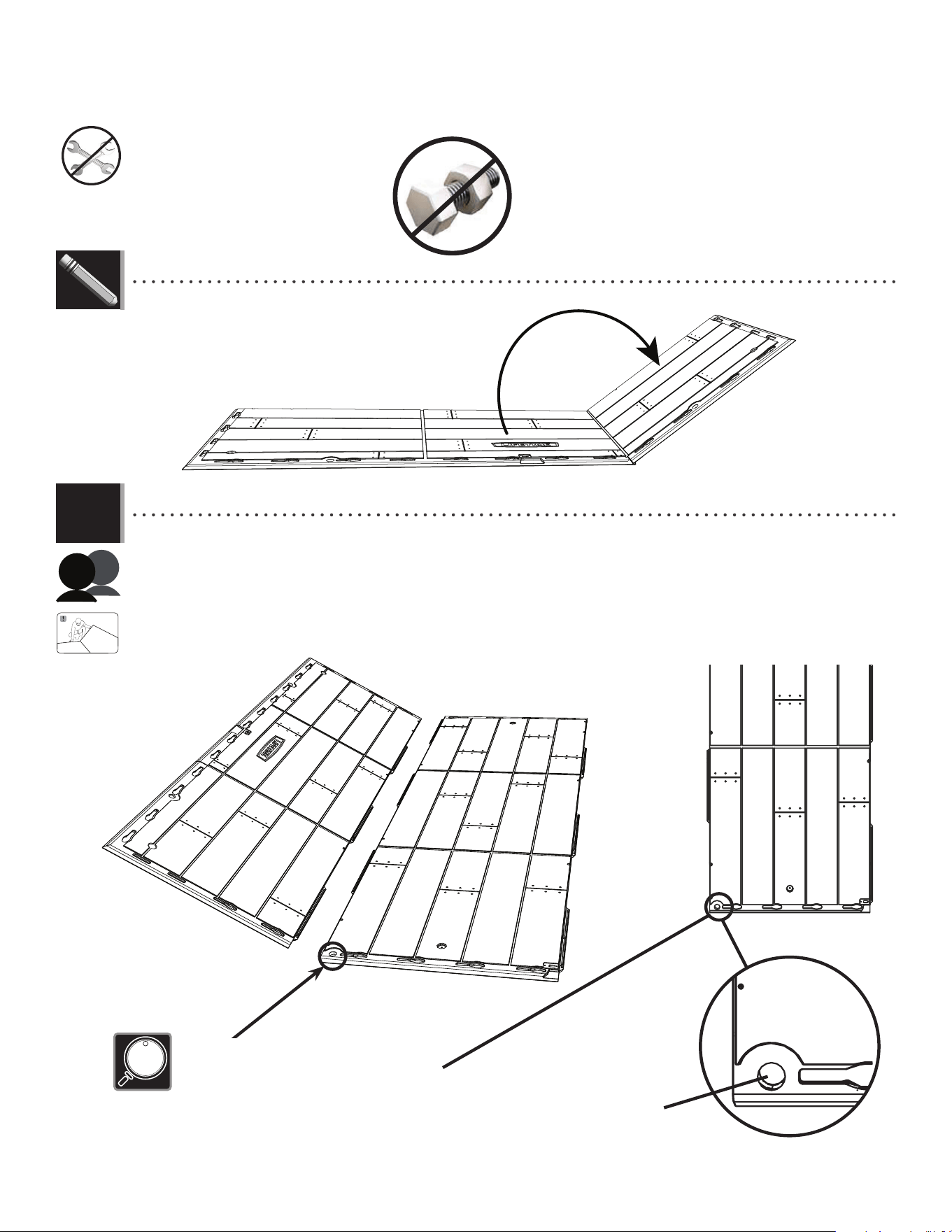
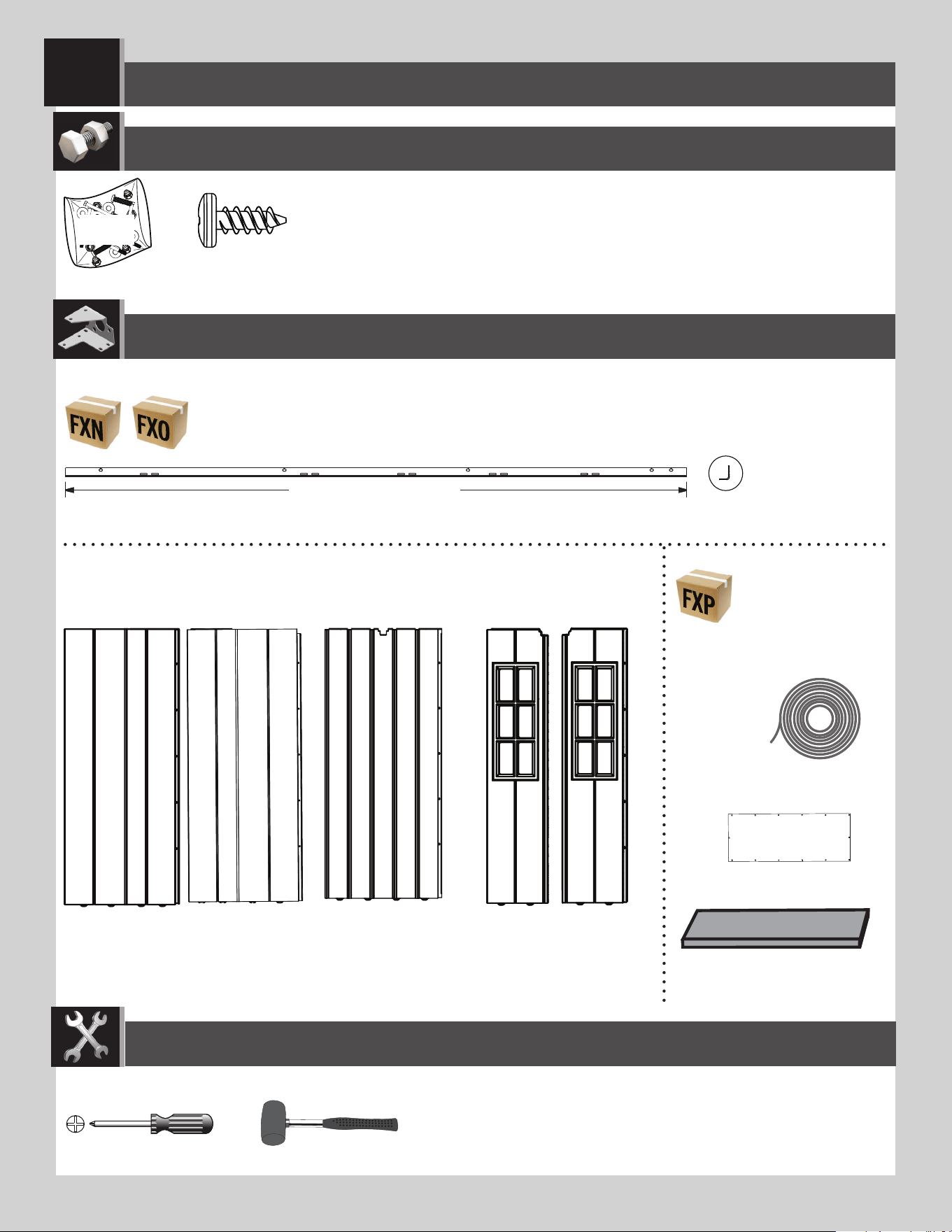
• Unfold the fl oor panels before installing.
• Dépliez les panneaux de sol avant l’installation.
• Despliegue los paneles del suelo antes de instalar.
ADC (x1)
AHO (x2)
HZA
• These screws do not anchor the fl oor; they only hold the panels together.
• Ces vis n’ancrent pas le plancher; ils ne servent que pour attacher les panneaux les uns avec les autres.
• Estos tornillos no anclan el piso; sirven sólo para sujetar los paneles los unos con los otros.
TOOLS REQUIRED / OUTILS REQUIS / INSTRUMENTAL REQUERIDO
(Not included—unless otherwise indicated*) / (Non inclus — sauf indication contraire*) / (No incluido, salvo indicación contraria*)
*ADC (x1)
CWU (x2)
GJZ (x24)
AHL (x1)
Parts / Pièces / Piezas
46
TOOLS AND HARDWARE REQUIRED / OUTILS ET QUINCAILLERIE REQUIS / INSTRUMENTAL Y HERRAJE REQUERIDOS
X SECTION 6 (CONTINUED) / SECTION 6 (SUITE) / SECCIÓN 6 (CONTINUACIÓN)
• Hold an inner fl oor panel (CUD) at an angle and slide the tabs along the edge underneath an outer fl oor panel (CUW). The tabs
interlock. Lay panel down fl at.
• Posez un panneau de plancher intérieur (CUD) à un angle et glissez les languettes le long du bord au-dessus du panneau de
plancher extérieur (CUW). Les languettes s’enclenchent les uns les autres. Étendez-le par terre.
• Coloque un panel de piso interior (CUD) a un ángulo y deslice las lenguetas a lo largo del borde debajo el panel de piso exterior
(CUW). Las lengüetas se entrelazan las unas con las otras. Aplánelo.
Hole / Trou / Agujero
• If the hole is not at this corner, turn the panel 180°.
• Si le trou n’est pas ici, tournez le panneau 180°.
• Si el agujero no está aquí, gire el panel 180°.
6.1
• Unfold the fl oor panels before installing.
• Dépliez les panneaux de sol avant l’installation.
• Despliegue los paneles del suelo antes de instalar.
LIFETIME
®
CUD
CUW
47
TOOLS AND HARDWARE REQUIRED / OUTILS ET QUINCAILLERIE REQUIS / INSTRUMENTAL Y HERRAJE REQUERIDOS
X SECTION 6 (CONTINUED) / SECTION 6 (SUITE) / SECCIÓN 6 (CONTINUACIÓN)
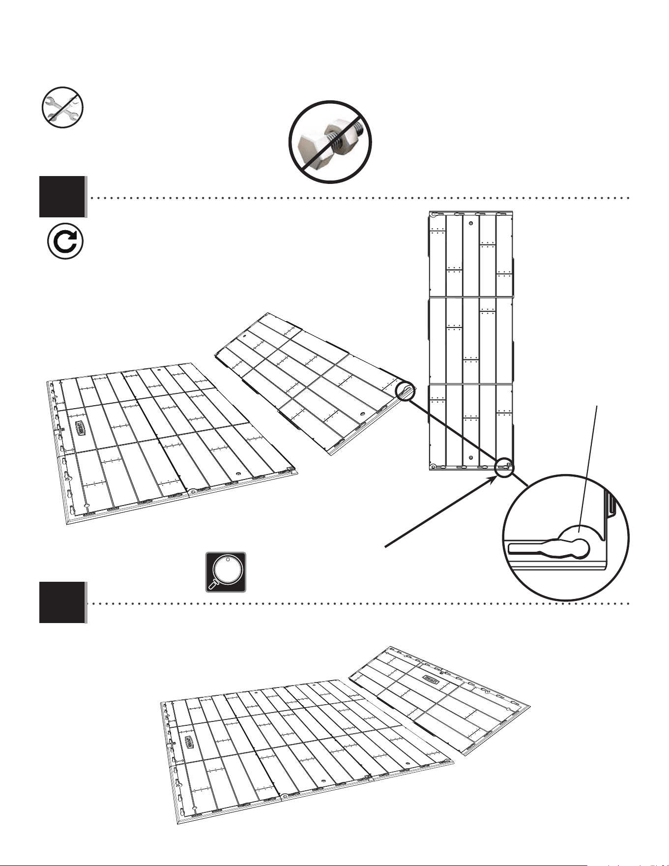
CUW
• Attach an outer fl oor panel (CUW) to the inner fl oor panel.
• Attachez un autre panneau de plancher intérieur (CUW) au panneau de plancher intérieur.
• Fije otro panel de piso exterior (CUW) al panel de piso interior.
CUD
Hole / Trou / Agujero
• If the hole is not at this corner, turn the Panel 180°.
• Si le trou n’est pas ici, tournez le panneau 180°.
• Si el agujero no está aquí, gire el panel 180°.
• Repeat the previous step.
• Répétez l’étape précédente.
• Repita el paso anterior.
6.2
6.3
48
TOOLS AND HARDWARE REQUIRED / OUTILS ET QUINCAILLERIE REQUIS / INSTRUMENTAL Y HERRAJE REQUERIDOS
X SECTION 6 (CONTINUED) / SECTION 6 (SUITE) / SECCIÓN 6 (CONTINUACIÓN)
AHO
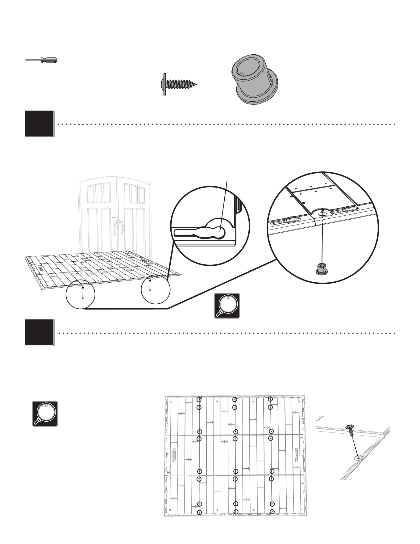
• Insert the screws (GJZ) through the divots in the fl oor panels and into the tabs of the adjacent fl oor panels. The divots are
near the seams of the fl oor panels.
• Insérez les vis (GJZ) à travers les marques dans les panneaux de plancher et dans les languettes du panneaux de
plancher contigu. Les marques se trouvent près des jonctions des panneaux de plancher.
• Introduzca los tornillos (GJZ) a través de las marcas en los paneles de piso y dentro de las lengüetas des los paneles de
piso adyacentes. Se encuentran las marcas cerca de las junturas de los paneles de piso.
AHO
• Decide on which edge you would like to install your doors. Insert bushings (AHO) through the holes in the fl oor.
• Choisissez l’extrémité où vous désireriez installer les portes. Insérez les bagues (AHO) à travers les trous dans le
plancher.
• Decide en cual borde le gustaría instalar las puertas. Introduzca los casquillos (AHO) a través de los agujeros en el piso.
AHO
AHO (x2)
• The slit in the bushing should face away from the fl oor.
• La fente dans la bague ne doit pas faire face au plancher.
• La rendija en el casquillo debe quedar en posición opuesta del piso.
• These screws do not anchor the fl oor; they
only hold the panels together.
• Ces vis n’ancrent pas le plancher; ils ne
servent que pour attacher les panneaux les
uns avec les autres.
• Estos tornillos no anclan el piso; sirven
sólo para sujetar los paneles los unos con
los otros.
6.4
6.5
GJZ
Hole / Trou / Agujero
GJZ (x24)
49
TOOLS AND HARDWARE REQUIRED / OUTILS ET QUINCAILLERIE REQUIS / INSTRUMENTAL Y HERRAJE REQUERIDOS
X SECTION 6 (CONTINUED) / SECTION 6 (SUITE) / SECCIÓN 6 (CONTINUACIÓN)
6.6
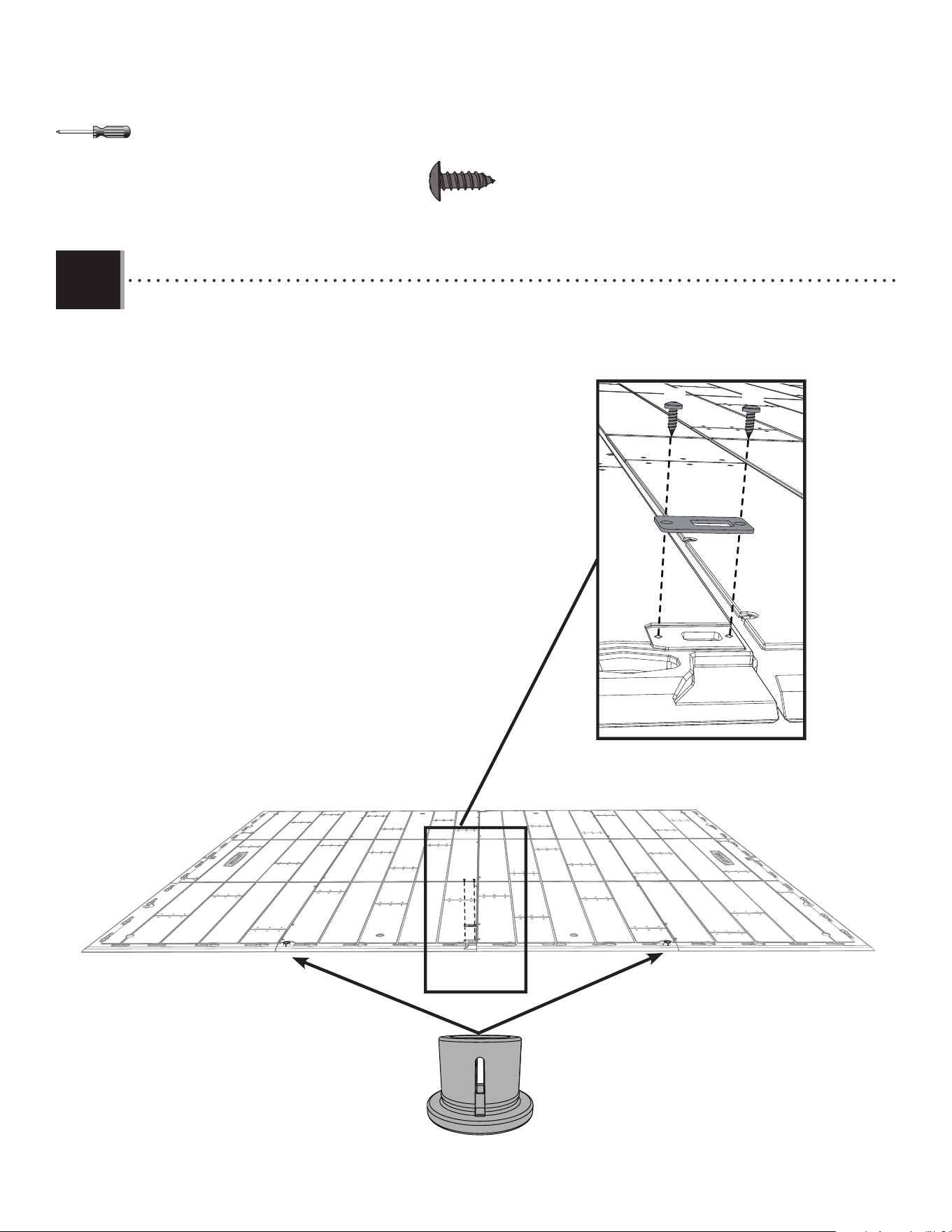
• Attach the strike plate (AHL) to the fl oor on the same side the bushings were installed.
• Attacher la gâche (AHL) au plancher sur le même côté que celui où les bagues ont été installées.
• Fijar la placa de impacto (AHL) al piso en el mismo lado donde se instalaron los casquillos.
CWU (x2)
Bushings
Bagues
Casquillos
CWU
CWU
5050
WALL ASSEMBLY / ASSEMBLAGE DES MURS / ENSAMBLAJE DE LOS MUROS
7
AFM (x9)
ADZ (x130)*
AIW (x1)
EDN
Metal parts / Pièces en métal / Piezas de metal
Plastic parts / Pièces en plastique / Piezas de plástico
PARTS REQUIRED / PIÈCES REQUISES / PIEZAS REQUERIDAS
HARDWARE REQUIRED / QUINCAILLERIE REQUISE / HERRAJE REQUERIDO
BDV (x2)
EPI (x2)
AHD (x7)
AGL (x2)
AGW (x2)
BDH (x1)
BDI (x1)
TOOLS REQUIRED / OUTILS REQUIS / INSTRUMENTAL REQUERIDO
(Not included—unless otherwise indicated*) / (Non inclus — sauf indication contraire*) / (No incluido, salvo indicación contraria*)
* Not all hardware will be used in the section.
* La quincaillerie n’est pas utilisée au complet dans la section.
* No se utilizará todo el herraje en la sección.
67 3/4 in/po (≈1,72 m)
67 3/4 in/po (≈172 cm)
51
TOOLS AND HARDWARE REQUIRED / OUTILS ET QUINCAILLERIE REQUIS / INSTRUMENTAL Y HERRAJE REQUERIDOS
X SECTION 7 (CONTINUED) / SECTION 7 (SUITE) / SECCIÓN 7 (CONTINUACIÓN)
7.1
x7
AFM
AFM
AHD
ADZ
ADZ
ADZ
ADZ
• The two holes go at the top.
• Les deux trous vont en haut.
• Los dos agujeros van hacia arriba.
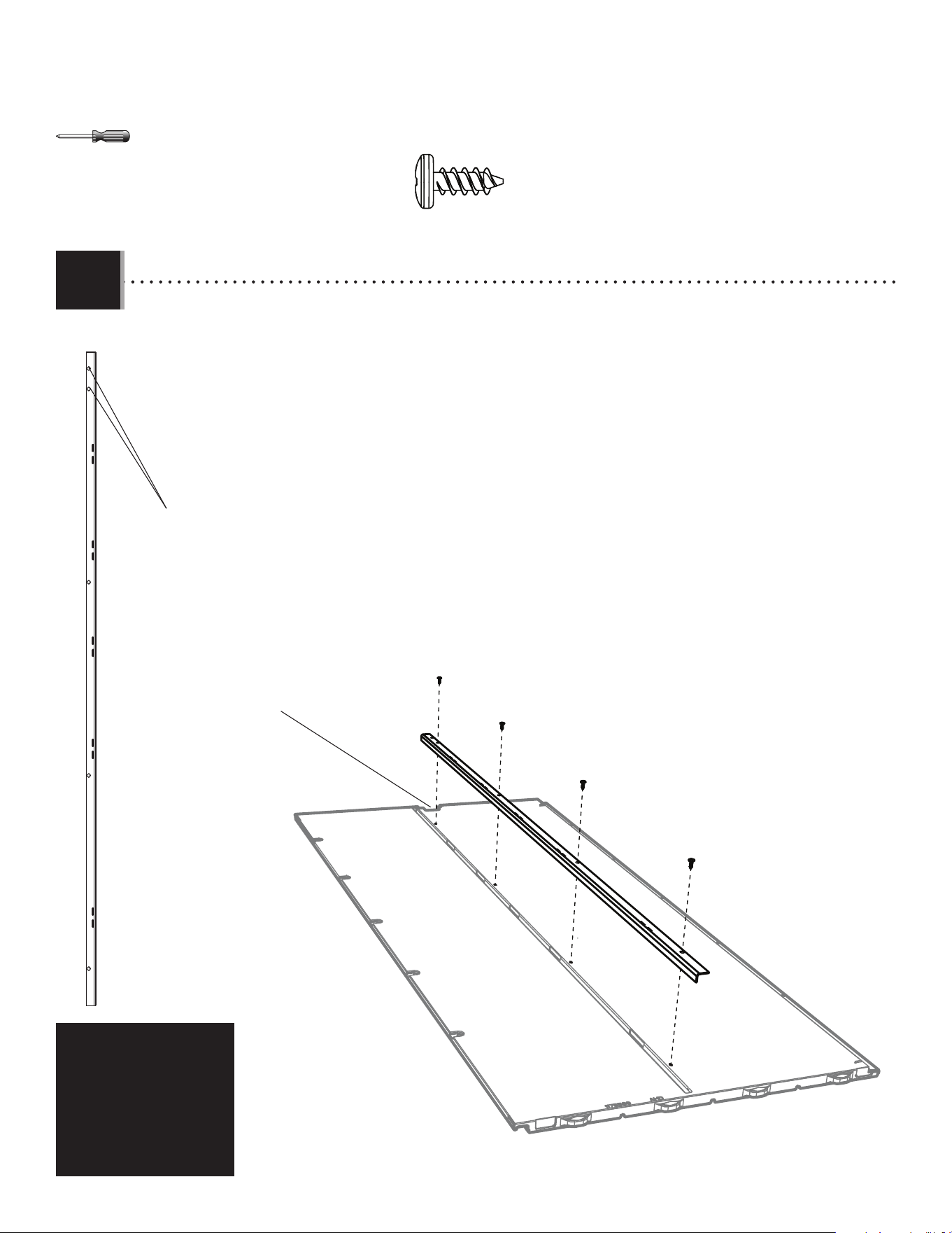
• Insert a wall channel (AFM) into the groove just to the left notch of the seven (7) wall panels (AHD) as shown. Secure with four
(4) screws (ADZ) for each one. The top hole is for manufacturing purposes only.
• Insérer un support mural (AFM) dans la rainure juste à gauche de l’encoche dans les sept (7) panneaux muraux (AHD) comme
illustré. Les fi xer à l’aide de quatre (4) vis (ADZ) chacun. Le trou supérieur est pour les fi ns de fabrication seulement.
• Insertar un soporte mural (AFM) en la ranura apenas a la izquierda de la muesca en los siete (7) paneles murales (AHD) como
se muestra. Fijarlos usando cuatro (4) tornillos (ADZ) cada uno. El agujero superior sirve sólo para los fi nes de fabricación.
• Notch
• Encoche
• Muesca
ADZ (x28)
52
TOOLS AND HARDWARE REQUIRED / OUTILS ET QUINCAILLERIE REQUIS / INSTRUMENTAL Y HERRAJE REQUERIDOS
X SECTION 7 (CONTINUED) / SECTION 7 (SUITE) / SECCIÓN 7 (CONTINUACIÓN)
• Insert a wall channel (AFM) into the fi rst groove
on the back of the right window wall panel (BDI) as
shown. Secure with four (4) screws (ADZ).
• Insérer un support mural (AFM) dans la première
rainure du panneau mural droit à fenêtre (BDI) comme
illustré. Fixer-le à l’aide de quatre (4) vis (ADZ).
• Insertar un soporte mural (AFM) en la primera
ranura del panel mural derecho para la ventana (BDI)
como se muestra. Fijarlo usando cuatro (4)
tornillos (ADZ).
• Insert a wall channel (AFM) into the fi rst
groove on the back of the left window wall
panel (BDH) as shown. Secure with four
(4) screws (ADZ).
• Insérer un support mural (AFM) dans la
première rainure du panneau mural gauche
à fenêtre (BDH) comme illustré. Fixer-le à
l’aide de quatre (4) vis (ADZ).
• Insertar un soporte mural (AFM) en la
primera ranura del panel mural izquierdo
para la ventana (BDH) como se muestra.
Fijarlo usando cuatro (4) tornillos (ADZ).
7.2
AFM
AFM
BDH
• The two holes go at the top.
• Les deux trous vont en haut.
• Los dos agujeros van hacia arriba.
ADZ (x8)
ADZ
ADZ
ADZ
ADZ
7.3
• The two holes go at the bottom.
• Les deux trous vont en bas.
• Los dos agujeros van hacia abajo.
BDI
ADZ
ADZ
ADZ
ADZ
53
TOOLS AND HARDWARE REQUIRED / OUTILS ET QUINCAILLERIE REQUIS / INSTRUMENTAL Y HERRAJE REQUERIDOS
X SECTION 7 (CONTINUED) / SECTION 7 (SUITE) / SECCIÓN 7 (CONTINUACIÓN)
7.4
EPI (x1)
• There is a narrow groove (illustrated in black) running along the outside of the window on the back of each narrow
window wall panel (BDH & BDI). Starting at the top, left corner of the groove in one of the narrow window wall panels, lay a
1/8" (3,2 mm) strip of the tan butyl tape (EPI) into the groove. Do not worry about getting the tape completely into the groove just yet—simply
lay the tape over the groove. Do not press the tape into the groove. Work your way downward (1), and curve to go along the bottom
(2) of the window. Curve your way upward (3) and then along the top (4) of the window until you’re back where you
started. Clip o the excess.
• Une rainure étroite (illustrée en noir) se trouve le long de l’extérieur de la fenêtre à l’arrière de chaque panneau
mural étroit. Partant du coin supérieur gauche de la rainure dans un panneau mural étroit avec fenêtre, étender
une goutte de 1/8 po (3,2 mm) de ruban de caoutchouc butyl couleur sable (EPI) dans la rainure. Ne pas s’inquiéter si la goutte n’est
pas complètement dans la rainure en ce moment, ne faire que déposer la goutte sur la rainure. Ne pas pousser la goutte dans la rainure.
Travailler vers le bas (1), et courber pour atteindre le bas (2) de la fenêtre. Courber vers le haut (3), puis le long du
haut (4) de la fenêtre jusqu’à revenir au point de départ. Couper l’excédent.
• Hay una ranura angosta (ilustrada en negro) bordeando la ventana en la superfi cie posterior de cada panel mural
angosto con ventana. Comenzando desde arriba, en la esquina izquierda de la ranura en un panel, aplicar una
línea de 3,2 mm (1/8 in) de cinta butílica de color cuero (EPI) en la ranura. No preocuparse por poner la cinta, mas solamente ponga la cinta
sobre la ranura. No presionar la cinta dentro de la ranura. Seguir hacia abajo (1), y curvearla a lo largo del borde inferior (2) de la
ventana. Curvearla hacia arriba (3) y, entonces, a lo largo del borde superior (4) de la ventana hasta estar al punto
de partida. Cortar el exceso.
Groove
Rainure
Ranura
1
2
3
4
54
TOOLS AND HARDWARE REQUIRED / OUTILS ET QUINCAILLERIE REQUIS / INSTRUMENTAL Y HERRAJE REQUERIDOS
X SECTION 7 (CONTINUED) / SECTION 7 (SUITE) / SECCIÓN 7 (CONTINUACIÓN)
7.5
• Peel o the protective backing from both sides of window pane (BDV). Align the holes in the pane with those in the
panel, and gently set a window pane down onto the panel. Secure the pane to the panel using fourteen (14) screws
(ADZ). Repeat steps 7.2–7.4 for the second narrow window wall panel.
• Retirer la pellicule protectrice des deux côtés du carreau (BDV). Aligner les trous dans le carreau avec ceux de la
porte, et, avec douceur, mettre le carreau sur la porte. Fixer le carreau à la porte en utilisant quatorze (14) vis (ADZ).
Répéter les étapes 7.2 – 7.4 pour le deuxième panneau mural étroit avec fenêtre.
• Retirar el protector de plástico de las dos caras de una hoja (BDV). Alinear los agujeros en la hoja con los de la
puerta, y colocar ligeramente la hoja de ventana en la puerta. Fijar la hoja a la puerta usando catorce (14) tornillos
(ADZ). Repetir los pasos 7.2–7.4 para la segunda panel mural angosto con ventana.
ADZ
ADZ
ADZ
ADZ
ADZ
ADZ
ADZ
ADZ
ADZ
ADZ
ADZ
ADZ
ADZ
ADZ
BDV
ADZ (x28)
EPI (x1)
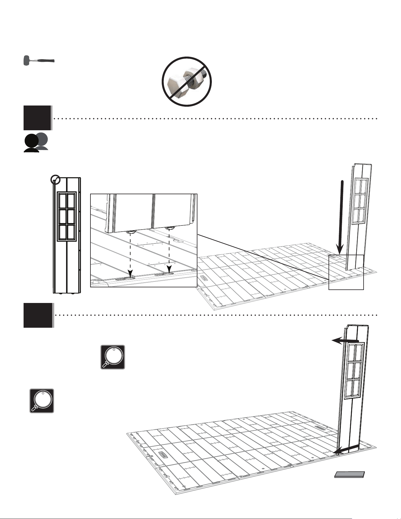
55
TOOLS AND HARDWARE REQUIRED / OUTILS ET QUINCAILLERIE REQUIS / INSTRUMENTAL Y HERRAJE REQUERIDOS
X SECTION 7 (CONTINUED) / SECTION 7 (SUITE) / SECCIÓN 7 (CONTINUACIÓN)
AIW (x1)
BDI
BDI
• Insert tabs at the bottom of the right window wall panel (BDI) into the third and fourth slots from the front, right corner of
the fl oor.
• Insérer les languettes au bord inférieur du panneau mural droit pour la fenêtre (BDI) dans les troisième et quatrième rainures
du coin droit du plancher.
• Insertar las lengüetas al borde inferior del panel mural derecho para la ventana (BDI) en las tercera y quarta ranuras de la
esquina derecha del piso.
• Slide the panel to the left.
• Faire glisser le panneau à gauche.
• Deslizar el panel a la izquierda.
• You may need to use a rubber mallet and the fl at side of the plastic block (AIW) to gently
tap the wall panel into place.
• Si besoin, utiliser un maillet en caoutchouc et le côté plat du bloc en plastique (AIW) pour
couper doucement en place le panneau mural.
• Si es necesario, usar un mazo de goma y el lado plano del bloque de plástico (AIW) para
golpear suavemente en su lugar el panel mural.
7.6
7.7
• If the bushings are in the way, temporarily remove them to insert the wall panel.
• Si les bagues interférent avec l’installation, les retirer temporairement pour pouvoir insérer le panneau mural.
• Si los casquillos interfi eren con la instalación, retirarlos temporalmente para poder insertar el panel mural.
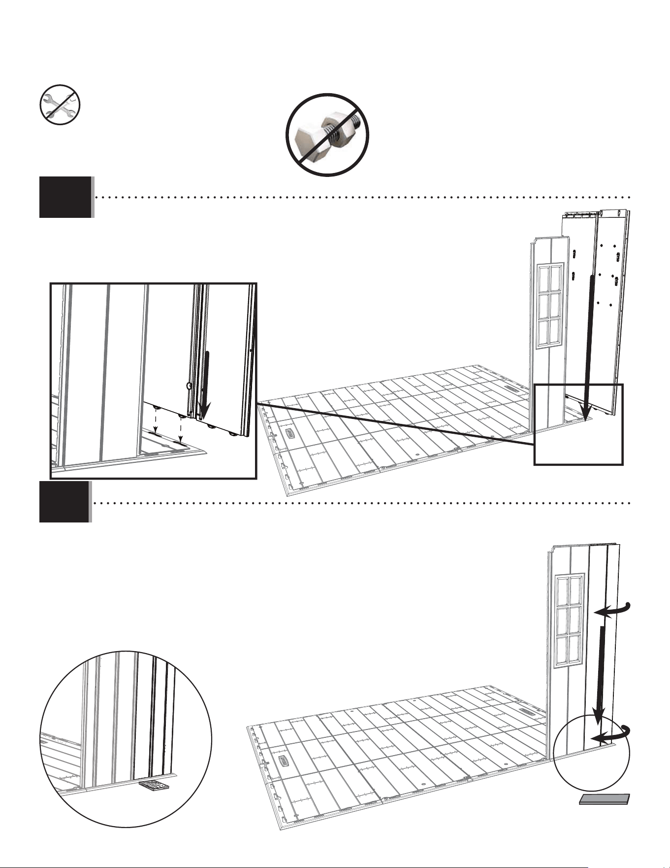
56
TOOLS AND HARDWARE REQUIRED / OUTILS ET QUINCAILLERIE REQUIS / INSTRUMENTAL Y HERRAJE REQUERIDOS
X SECTION 7 (CONTINUED) / SECTION 7 (SUITE) / SECCIÓN 7 (CONTINUACIÓN)
AIW (x1)
• Insert tabs at the bottom of the corner panel (AGW) into the fi rst two slots along the right edge of
the fl oor, and slide the panel toward the front of the fl oor.
• Insérer les languettes au bord inférieur du panneau angulaire (AGW) dans les premières rainures le
long du bord droit du plancher, et faire glisser le panneau vers la partie avant de l’abri.
• Insertar las lengüetas al borde inferior del panel angular (AGW) en las primeras dos ranuras a lo
largo del borde derecho del piso, y deslizar el panel hacia la parte delantera de la caseta.
• Bend the corner panel as shown, and pull down to snap the tabs into the fi rst two slots from the
right corner of the fl oor. Place the plastic block (AIW) underneath the fl oor and directly underneath
the tab being inserted to help with insertion.
• Plier le panneau angulaire comme indiqué, tirer le panneau vers le bas, et insérer les
languettes dans les premières deux encoches du coin vant doir. Pour aider avec l’insertion,
mettre le bloc en plastique (AIW) sous le plancher et directement sous la languette à insérer.
• Desplegar el panel angular como se muestra, tirar para abajo el panel, e insertar las lengüetas
en las dos primeras muescas de la esquina delantera derecha. Para ayudar con la inserción,
colocar el bloque de plástico (AIW) debajo el piso y directamente debajo de la lengüeta a insertar.
AGW
7.9
AIW
7.8
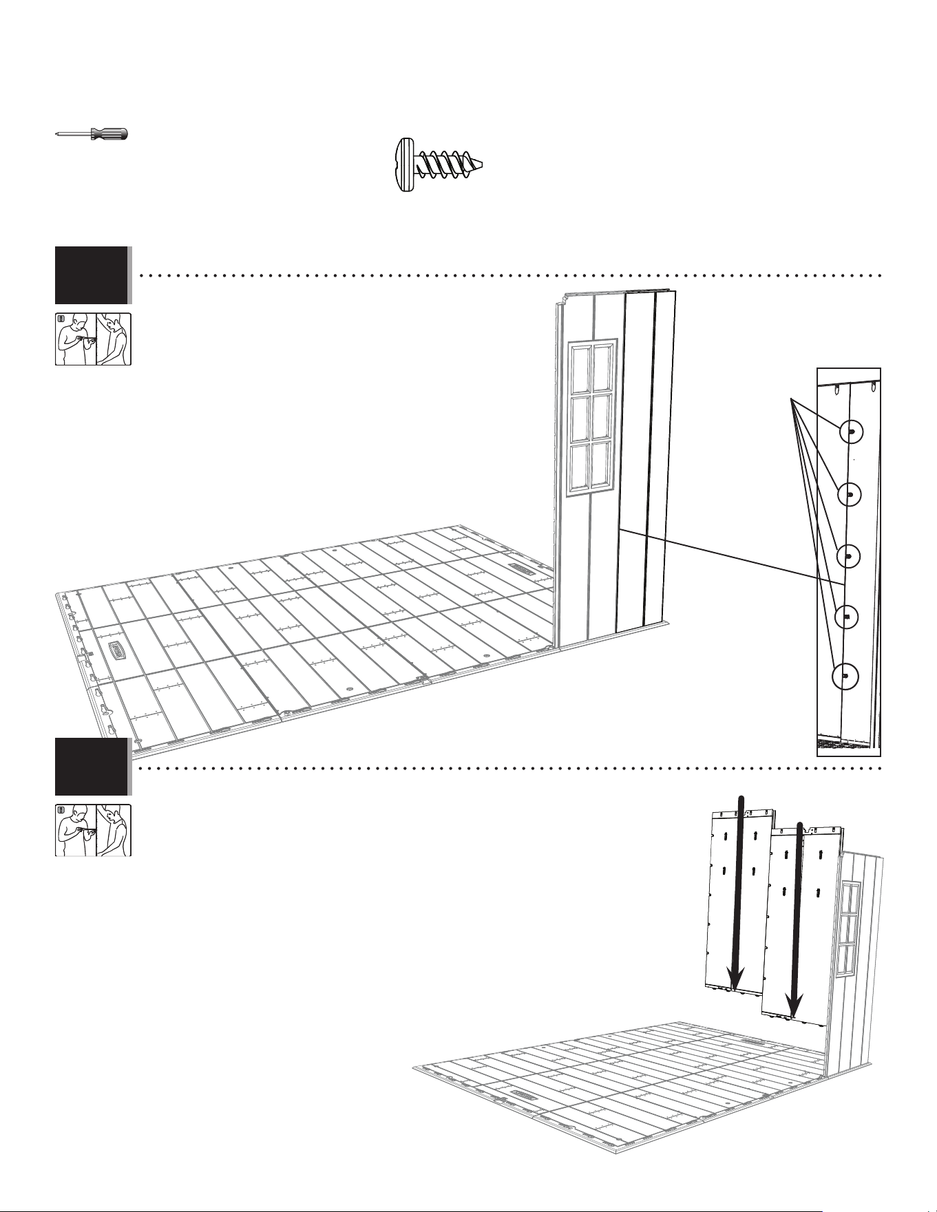
57
TOOLS AND HARDWARE REQUIRED / OUTILS ET QUINCAILLERIE REQUIS / INSTRUMENTAL Y HERRAJE REQUERIDOS
X SECTION 7 (CONTINUED) / SECTION 7 (SUITE) / SECCIÓN 7 (CONTINUACIÓN)
ADZ (x15)
ADZ
• Secure the two panels using fi ve (5) screws (ADZ). The attachment
points may have a thin membrane that the screws will puncture.
• Fixer bien les deux panneaux à l’aide de cinq (5) vis (ADZ). Les
points de fi xation peuvent avoir une fi ne membrane que les vis perceront.
• Fijar los dos paneles usando cinco (5) tornillos (ADZ). Los puntos
de fi jación pueden tener una membrana delgada que los tornillos perforarán.
• Insert two (2) wall panels (AHD), and secure using fi ve (5) screws (ADZ) each.
• Insérer deux (2) panneaux muraux (AHD), et attacher-les l’un à l’autre à l’aide de cinq (5)
vis (ADZ) chacun.
• Insertar dos (2) paneles de pared (AHD), y sujetarlos usando cinco (5) tornillos (ADZ) cada
uno.
AHD
AHD
7.11
7.10
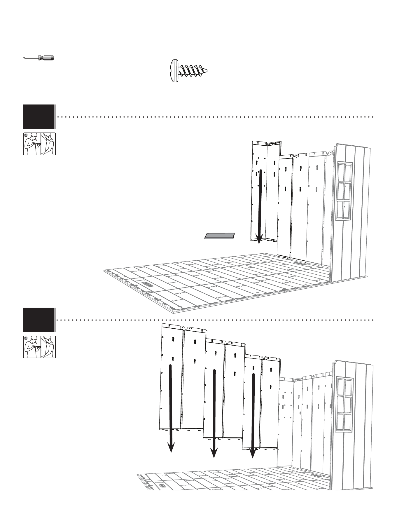
58
TOOLS AND HARDWARE REQUIRED / OUTILS ET QUINCAILLERIE REQUIS / INSTRUMENTAL Y HERRAJE REQUERIDOS
X SECTION 7 (CONTINUED) / SECTION 7 (SUITE) / SECCIÓN 7 (CONTINUACIÓN)
AHD
AHD
AHD
ADZ (x20)
AIW (x1)
AGL
• For the right, rear corner panel (AGL), repeat the step done for the right,
front corner panel.
• Pour le panneau angulaire (AGL) arrière droit, répéter les étapes réalisées
pour le panneau angulaire avant droit.
• Para el panel angular (AGL) trasero derecho, repetir los pasos efectuados
para el panel angular delantero derecho.
• Insert three (3) wall panels (AHD)
along the rear edge of the
fl oor, and secure using fi ve (5)
screws (ADZ) each.
• Insérer trois (3) panneaux muraux
(AHD) le long du bord arrière
du plancher, et les fi xer l’un à
l’autre à l’aide de cinq (5) vis
(ADZ) chacun.
• Insertar tres (3) paneles de pared
(AHD) a lo largo del borde
trasero del piso, y sujetarlos
usando cinco (5) tornillos (ADZ)
cada uno.
7.12
7.13
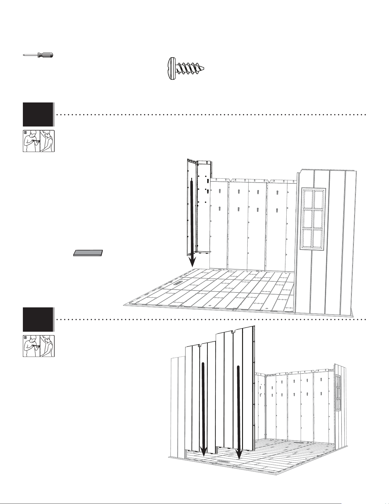
59
TOOLS AND HARDWARE REQUIRED / OUTILS ET QUINCAILLERIE REQUIS / INSTRUMENTAL Y HERRAJE REQUERIDOS
X SECTION 7 (CONTINUED) / SECTION 7 (SUITE) / SECCIÓN 7 (CONTINUACIÓN)
• For the left, rear corner panel (AGW), repeat the step you did for the right, front corner panel.
• Pour le panneau angulaire (AGW) arrière gauche, répéter les étapes réalisées pour le panneau angulaire avant droit.
• Para el panel angular (AGW) trasero izquierdo, repetir los pasos efectuados para el panel angular delantero derecho.
ADZ (x15)
AGW
AHD
AHD
AIW (x1)
• Insert two (2) wall panels (AHD), and secure
using fi ve (5) screws (ADZ) each.
• Insérer deux (2) panneaux muraux (AHD), et
les fi xer l’un à l’autre à l’aide de cinq
(5) vis (ADZ) chacun.
• Insertar dos (2) paneles de pared (AHD), y
fi jarlos usando cinco (5) tornillos (ADZ)
cada uno.
7.14
7.15
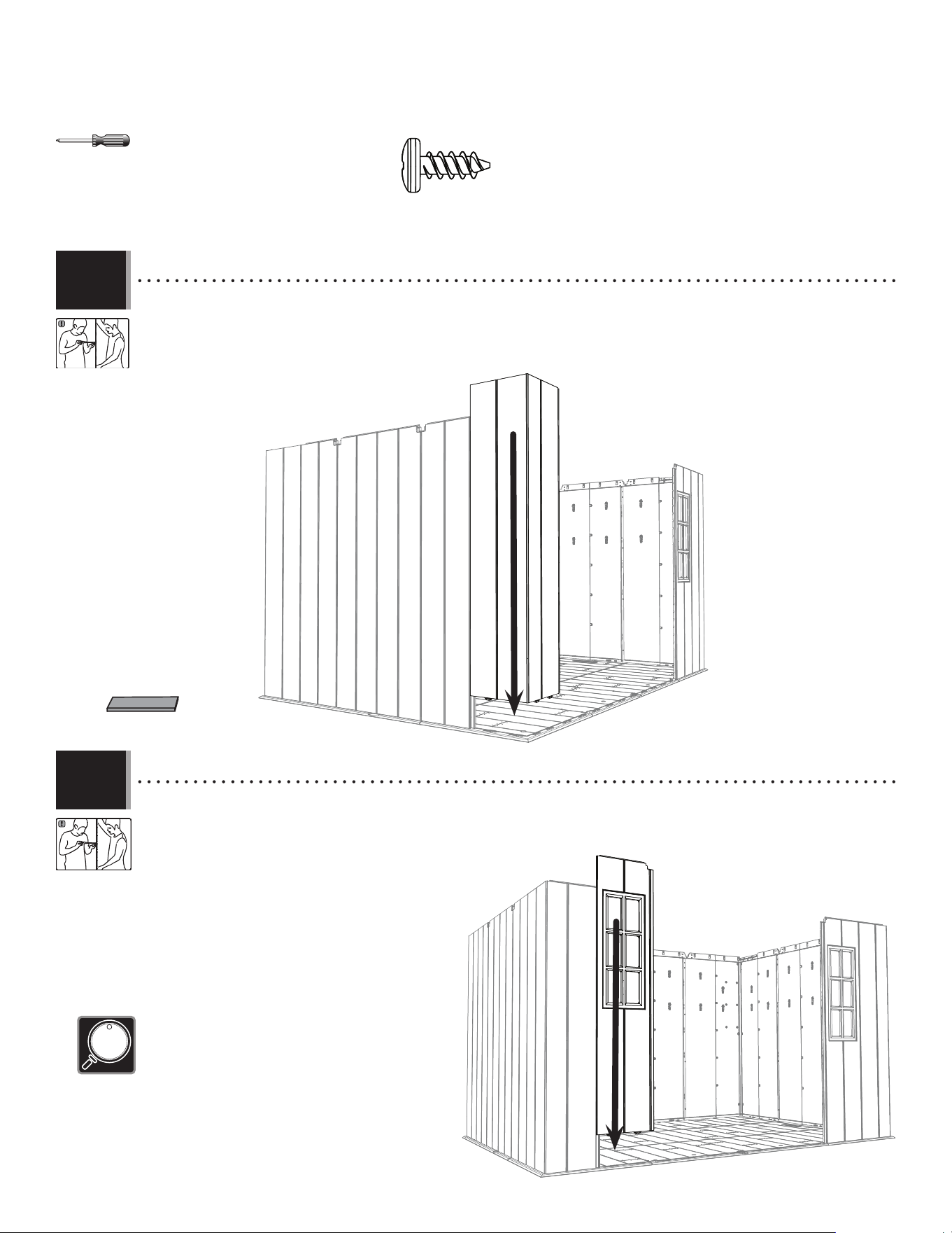
60
TOOLS AND HARDWARE REQUIRED / OUTILS ET QUINCAILLERIE REQUIS / INSTRUMENTAL Y HERRAJE REQUERIDOS
X SECTION 7 (CONTINUED) / SECTION 7 (SUITE) / SECCIÓN 7 (CONTINUACIÓN)
ADZ (x10)
AIW (x1)
AGL
• For the left, front corner panel (AGL), repeat the step you did for the right, front corner panel.
• Pour le panneau angulaire (AGL) avant gauche, répéter les étapes réalisées pour le panneau angulaire avant droit.
• Para el panel angular (AGL) delantero izquierdo, repetir los pasos que se efectuaron para el panel angular delantero
derecho.
BDH
• Insert tabs at the bottom of the left window wall panel (BDH) into the third and fourth slots from the front, right corner of
the fl oor. Slide the panel to the left. Secure the two panels using fi ve (5) screws (ADZ).
• Insérer les languettes au bord inférieur du panneau mural gauche pour la fenêtre (BDH) dans les troisième et quatrième
rainures du coin droit du plancher. Faire
glisser le panneau à gauche. Fixer bien les
deux panneaux à l’aide de cinq (5) vis (ADZ).
• Insertar las lengüetas al borde inferior del panel
mural izquierdo para la ventana (BDH) en las tercera y
quarta ranuras de la esquina derecha del piso.
Deslizar el panel a la izquierda. Fijar los dos
paneles usando cinco (5) tornillos (ADZ).
7.16
7.17
• If the bushings are in the way, temporarily remove them to
insert the wall panel.
• Si les bagues interférent avec l’installation, les retirer tempo-
rairement pour pouvoir insérer le panneau mural.
• Si los casquillos interfi eren con la instalación, retirarlos
temporalmente para poder insertar el panel mural.
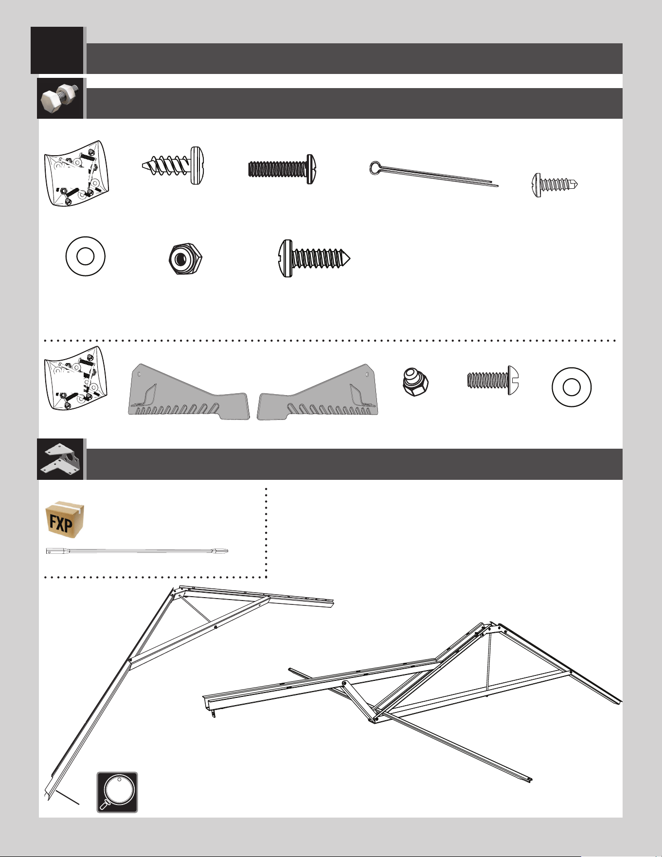
6161
8
ROOF ASSEMBLY / ASSEMBLAGE DU TOIT / ENSAMBLAJE DEL TEJADO
AHP (x2)
ADZ (x155)*
DTV (x2)
CXK (x2)
AEE (x2)
(x2)
(x1)
AFL (x6)
FXQ
Metal Parts / Pièces en métal / Piezas de metal
PARTS REQUIRED / PIÈCES REQUISES / PIEZAS REQUERIDAS
HARDWARE REQUIRED / QUINCAILLERIE REQUISE / HERRAJE REQUERIDO
• This notched end goes towards the front of the shed.
• Cette extrémité encochée va vers la partie avant de l’abri.
• Este extremo muescado va hacia la parte delantera de la caseta.
ECT
ECS (x1)
ADK (x2)
BZA (x2)
AEE (x4)
ECR (x1)
ARV (x4)
* Not all hardware will be used in the section.
* La quincaillerie n’est pas utilisée au complet dans la section.
* No se utilizará todo el herraje en la sección.
BHJ (x2)
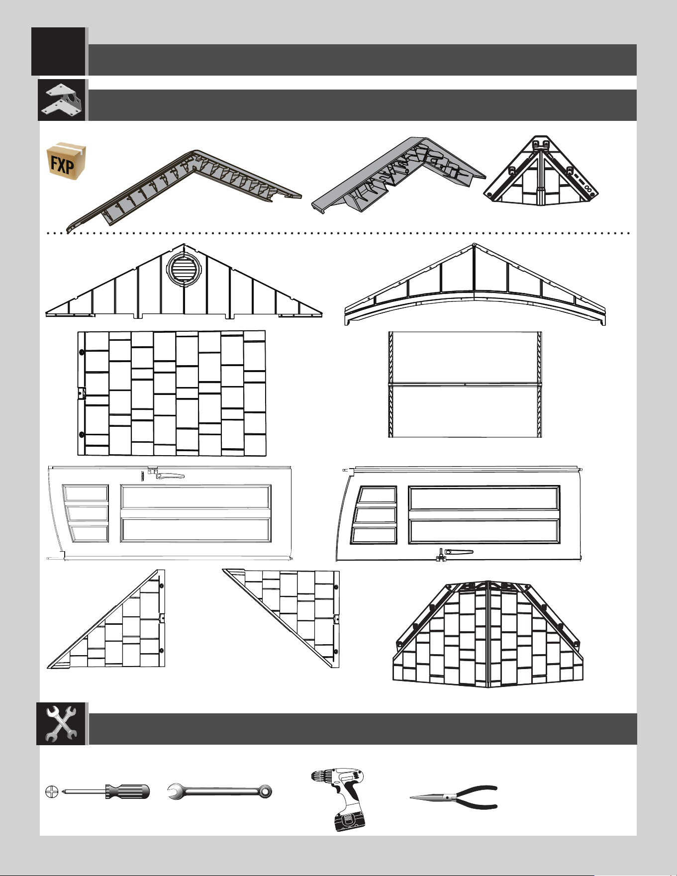
6262
8
ROOF ASSEMBLY / ASSEMBLAGE DU TOIT / ENSAMBLAJE DEL TEJADO
(x2)
(x1)
(x1) (x1)
BDS (x1)
DRA (x1)
DRB (x1)
BDR (x1)
3/8 in/po (≈10 mm)
Plastic Parts / Pièces en plastique / Piezas de plástico
PARTS REQUIRED / PIÈCES REQUISES / PIEZAS REQUERIDAS
HOB (x3)
AGQ (x6)
HOC (x2)
TOOLS REQUIRED / OUTILS REQUIS / INSTRUMENTAL REQUERIDO
(Not included—unless otherwise indicated*) / (Non inclus — sauf indication contraire*) / (No incluido, salvo indicación contratia*)
HLF (x4)
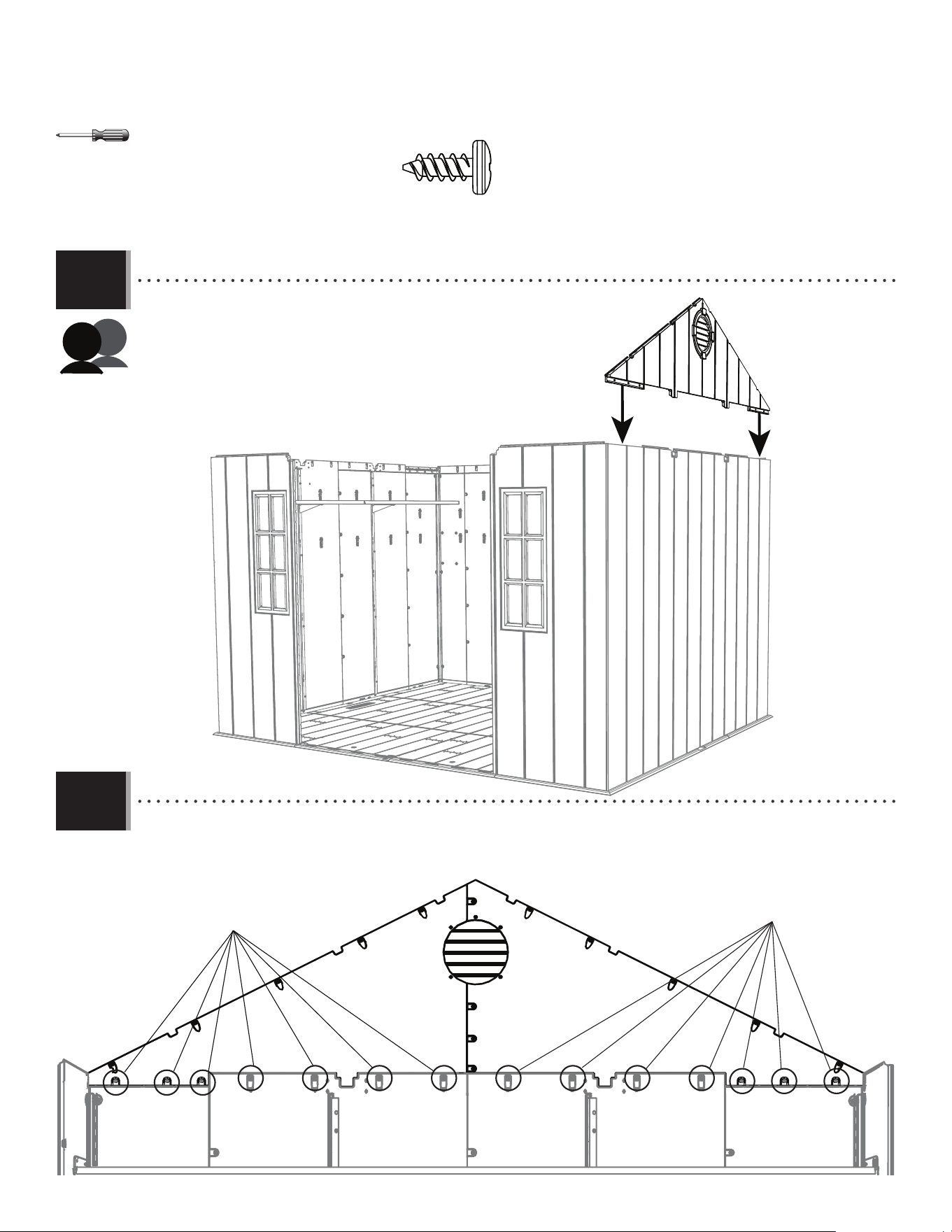
63
TOOLS AND HARDWARE REQUIRED / OUTILS ET QUINCAILLERIE REQUIS / INSTRUMENTAL Y HERRAJE REQUERIDO
X SECTION 9 (CONTINUED) / SECTION 9 (SUITE) / SECCIÓN 9 (CONTINUACIÓN)
ADZ (x14)
ADZ
ADZ
• Set a side gable down onto the right side of the shed.
• Mettre un pignon latéral sur le côté droit de l’abri.
• Meter una fachada lateral en el lado derecho de la caseta.
• Secure a side gable to the shed using fourteen (14) screws (ADZ).
• Fixer un pignon latéral à l’abri à l’aide de quatorze (14) vis (ADZ).
• Fijar una fachada lateral a la caseta usando catorce (14) tornillos (ADZ).
8.1
8.2
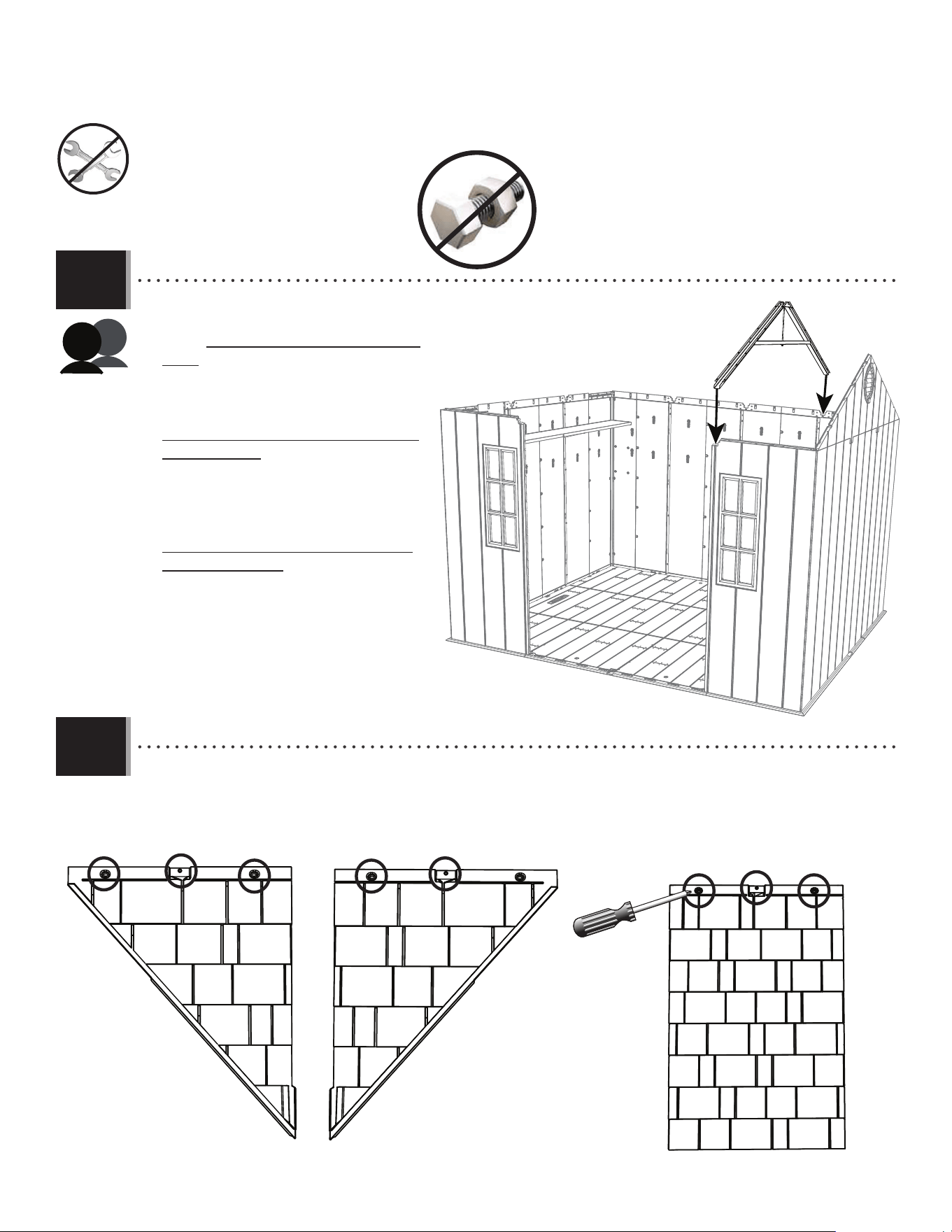
64
TOOLS AND HARDWARE REQUIRED / OUTILS ET QUINCAILLERIE REQUIS / INSTRUMENTAL Y HERRAJE REQUERIDO
X SECTION 9 (CONTINUED) / SECTION 9 (SUITE) / SECCIÓN 9 (CONTINUACIÓN)
8.3
• Place a side truss into the notches on the
rear wall panel and right front window wall
panel. While another adult holds this in
place, continue to the next step.
• Mettre une ferme latérale dans les en-
coches sur le panneau mural arrière et le
panneau mural avant droit pour la fenêtre.
Pendant qu’un autre adulte soutient la
ferme en place, continuer à la prochaine
étape.
• Meter una cercha lateral en las muescas
en el panel mural trasero y el panel mural
delantero derecho para la ventana.
Mientras que otro adulto mantenga la
cercha en su lugar, seguir al próximo
paso.
• Using a screwdriver, punch holes in the locations indicated at the top edge of the roof panels.
• En utilisant une tournevis, poinçonner trous dans les endroits indiqués au bord supérieur des panneaux de toit.
• Usando un destornillador, perforar orifi cios en las ubicaciones indicadas en el borde superior de los paneles de
tejado.
8.4
AGQ
BDS
BDR
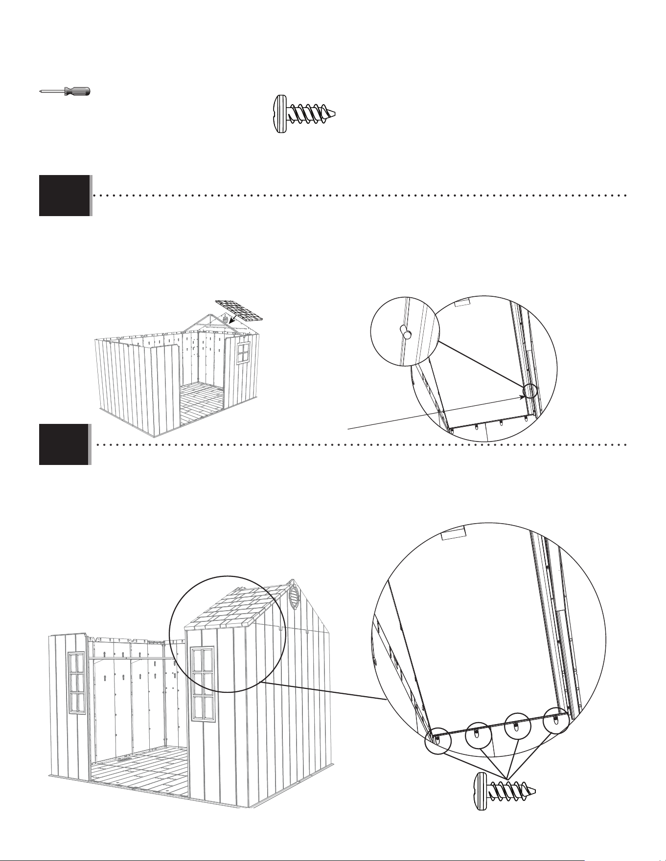
65
TOOLS AND HARDWARE REQUIRED / OUTILS ET QUINCAILLERIE REQUIS / INSTRUMENTAL Y HERRAJE REQUERIDO
X SECTION 9 (CONTINUED) / SECTION 9 (SUITE) / SECCIÓN 9 (CONTINUACIÓN)
ADZ (x4)
• Align the four holes in the wall panel with those at the bottom of the roof panel, and insert four (4) screws (ADZ) to
secure the panel in place.
• Aligner les quatre trous dans le panneau mural avec ceux au bord inférieur du panneau de toit, et insérer quatre
(4) vis (ADZ) pour attacher le panneau en place.
• Alinear los cuatro agujeros en el panel de pared con los al borde inferior del panel de tejado, e insertar cuatro
(4) tornillos (ADZ) para sujetarlo en su lugar.
ADZ (x4)
8.6
8.5
AGQ
Alignment nub
Petite bosse d’alignement
Bulto de alineamiento
• Set the roof panel (AGQ) down onto the wall panel, gable, and truss. The groove at the bottom of the roof panel sets
over the top of the wall panel. Ensure the alignment nub fi ts into the notch in the truss.
• Mettre le panneau de toit (AGQ) dans le panneau mural, le pignon, et la ferme. Mettez la rainure au bord inférieur du
panneau de toit sur la partie supérieure du panneau mural. Mettre la petite bosse d’alignement dans l’encoche
de la ferme.
• Colocar el panel de tejado (AGQ) en el panel de pared, la fachada, y la cercha. Colocar la ranura a lo largo del borde
inferior del panel de tejado sobre la parte superior del panel de pared. Encajar el bulto de alineamiento en la
muesca en la cercha.
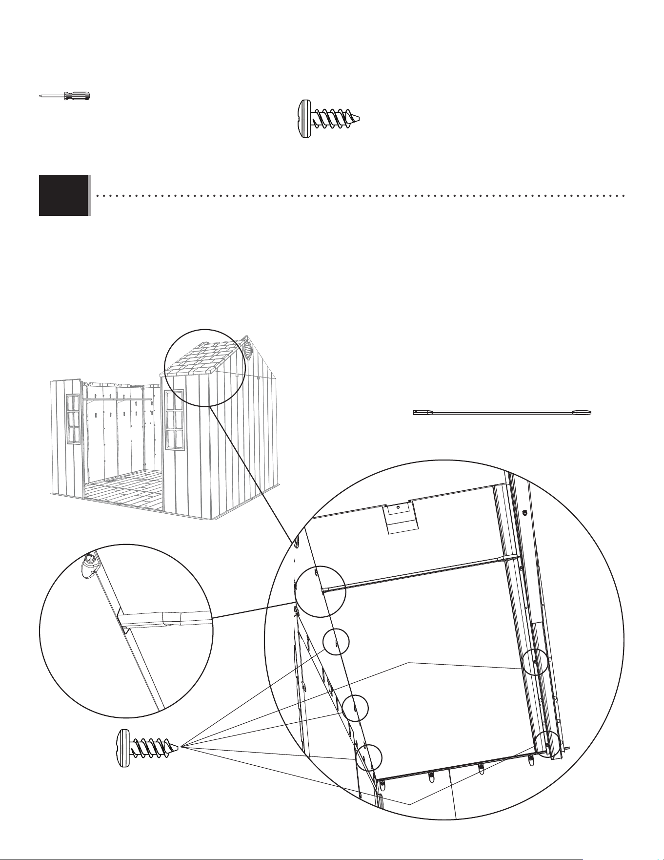
66
TOOLS AND HARDWARE REQUIRED / OUTILS ET QUINCAILLERIE REQUIS / INSTRUMENTAL Y HERRAJE REQUERIDO
X SECTION 9 (CONTINUED) / SECTION 9 (SUITE) / SECCIÓN 9 (CONTINUACIÓN)
ADZ (x5)
ADZ (x5)
AFL
AFL
• Insert the fi rst three screws (ADZ) through the gable and into the roof panel, and the next two screws (ADZ) through the
truss and into the roof panel at the locations shown. Then, insert the roof support (AFL) into the notches in the gable
and between the truss and the roof panel.
• Insérer les premières trois vis (ADZ) à travers le pignon et dans le panneau de toit avec lucarne et les premières
deux vis (ADZ) suivantes à travers la ferme et dans le panneau de toit aux emplacements indiqués. Ensuite, mettre
le support de toit (AFL) dans les encoches dans le pignon et entre le panneau de toit et la ferme.
• Insertar los primeros tres tornillos (ADZ) por la fachada y dentro del panel de tejado con tragaluz y los siguientes dos
tornillos (ADZ) por la cercha y dentro del panel de tejado a las ubicaciones indicadas. Entonces, insertar el soporte de
tejado (AFL) en las muescas en la fachada y entre la cercha y el panel de tejado.
AFL (x1)
8.7
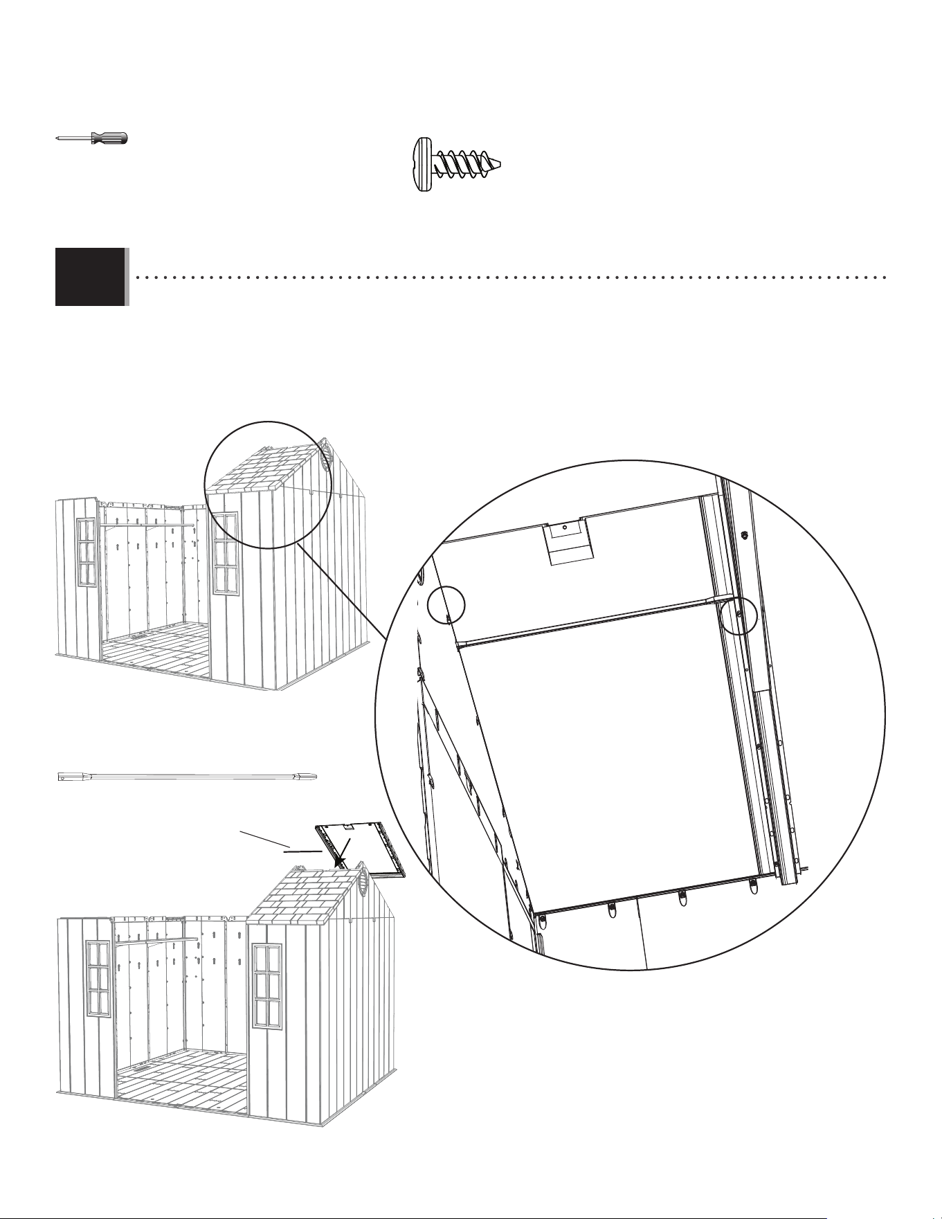
67
TOOLS AND HARDWARE REQUIRED / OUTILS ET QUINCAILLERIE REQUIS / INSTRUMENTAL Y HERRAJE REQUERIDO
X SECTION 9 (CONTINUED) / SECTION 9 (SUITE) / SECCIÓN 9 (CONTINUACIÓN)
ADZ (x13)
AFL (1)
AGQ
• Insert one screw (ADZ) through the gable and into the roof panel and one screw (ADZ) through the truss and into the
roof panel at the locations shown. Repeat the previous steps for the rear corner roof panel (AGQ).
• Insérer une vis (ADZ) à travers le pignon et dans le panneau de toit et une vis (ADZ) à travers la ferme et dans le
panneau de toit aux emplacements illustrés. Répéter les étapes précédentes pour le panneau de toit (AGQ) arrière droit.
• Insertar un tornillo (ADZ) por la fachada y dentro del panel de tejado y un tornillo (ADZ) por la cercha y dentro del panel
de tejado a las ubicaciones indicadas. Repetir los pasos anteriores para el panel de tejado (AGQ) trasero derecho.
AFL (x1)
8.8
AFL
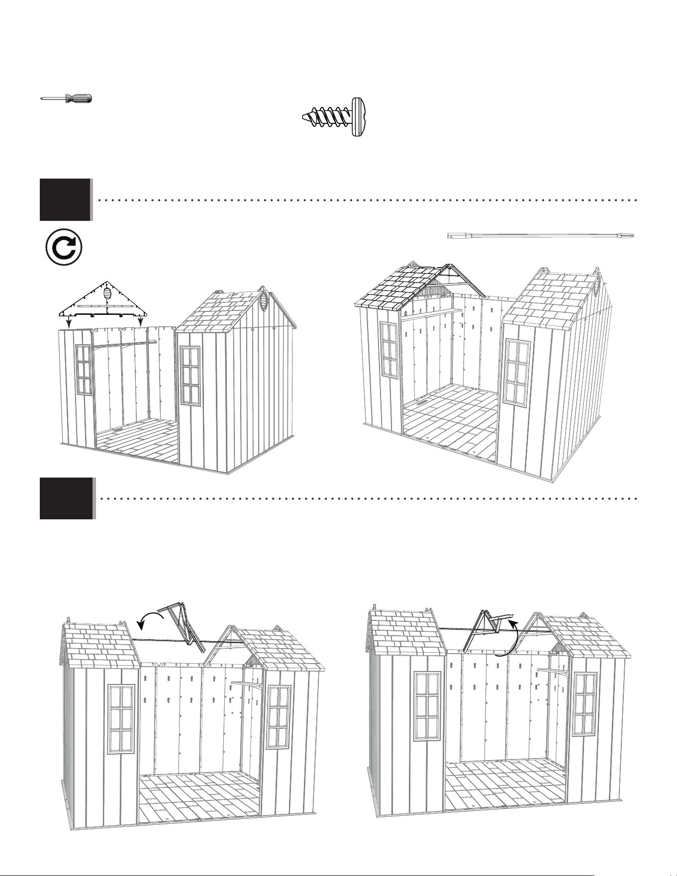
68
TOOLS AND HARDWARE REQUIRED / OUTILS ET QUINCAILLERIE REQUIS / INSTRUMENTAL Y HERRAJE REQUERIDO
X SECTION 9 (CONTINUED) / SECTION 9 (SUITE) / SECCIÓN 9 (CONTINUACIÓN)
ADZ (x36)
AGQ
AGQ
AFL (x2)
• Place the back of the center truss into the notch on the center rear wall panel. Then, lift the front of the truss up
so the ends of the roof support tube touch the side trusses.
• Mettre l’extrémité arrière de la ferme centrale dans l’encoche sur le panneau mural arrière central. Ensuite,
soulever l’extrémité avant de la ferme pour que les extrémités du tube de support touchent les fermes latéraux.
• Meter el extremo trasero de la cercha central en la muesca en el panel de tejado central trasero. Entonces,
levantar el extremo delantero de la cercha para arriba para que los extremos del tubo de soporte hagan contacto
con las cerchas laterales.
• Repeat steps 8.1–8.8 for the left side of the shed.
• Répéter les étapes 8.1 – 8.8 pour le côté droit de l’abri.
• Repetir los pasos 8.1–8.8 para el lado izquierdo de la caseta.
8.9
8.10
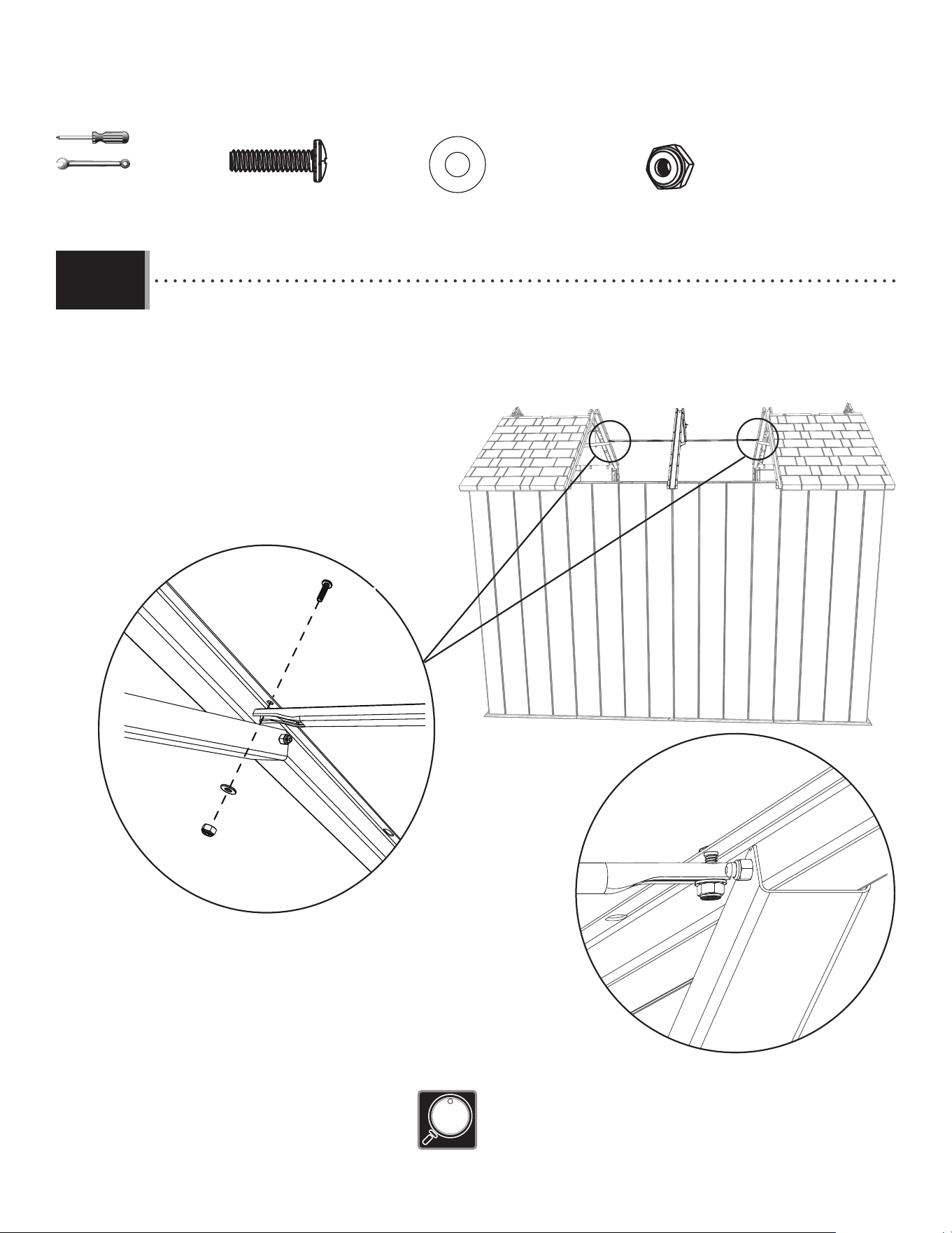
69
TOOLS AND HARDWARE REQUIRED / OUTILS ET QUINCAILLERIE REQUIS / INSTRUMENTAL Y HERRAJE REQUERIDO
X SECTION 9 (CONTINUED) / SECTION 9 (SUITE) / SECCIÓN 9 (CONTINUACIÓN)
3/8 in/po
(≈10 mm)
DTV (x2)
CXK (x2)
AEE (x2)
• Secure the ends of the support tube to the side truss channels using the hardware provided.
• Fixer bien les extrémités du tube de support aux fermes latéraux à l’aide de la quincaillerie incluse.
• Fijar los extremos del tubo de soporte a las cerchas laterales usando el herraje incluido.
8.11
DTV
AEE
CXK
• The support tube goes underneath the lateral truss.
• Attacher bien le tube de support en dessous de la ferme latérale.
• Se sujete el tubo de soporte debajo la cercha lateral.
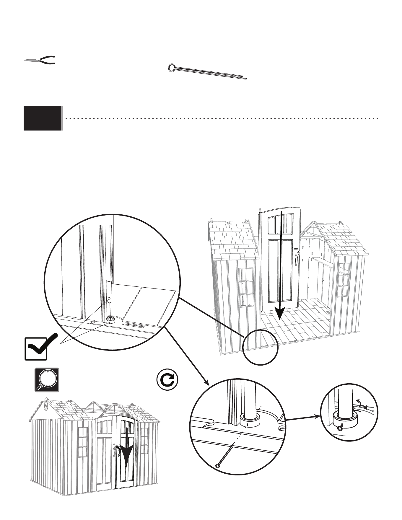
70
TOOLS AND HARDWARE REQUIRED / OUTILS ET QUINCAILLERIE REQUIS / INSTRUMENTAL Y HERRAJE REQUERIDO
X SECTION 9 (CONTINUED) / SECTION 9 (SUITE) / SECCIÓN 9 (CONTINUACIÓN)
AHP (x2)
AHP
• Pull the hinge tube down out of the left door about six inches. Align the hole at the bottom of the hinge tube
with the slit in the bushing, and insert the tube. Insert a cotter pin (AHP) and bend the ends.
• Étender le tube d’articulation à peu près quinze centimètres du bord inférieur de la porte. Aligner le trou
dans la partie inférieure du tube avec la fente dans la bague, et insérer le tube. Insérer une clavette (AHP) et pliez
les extrémités.
• Extender el tubo de articulación unos qunice centimetros del borde inferior de la puerta. Alinear el agujero
en la parte inferior del tubo con la rendija en el casquillo, e insertar el tubo. Insertar una clavija (AHP) y doble los
extremos.
8.12
• Repeat this step for the right door.
• Répéter cette étape pour la porte droite.
• Repetir este paso para la puerta derecha.
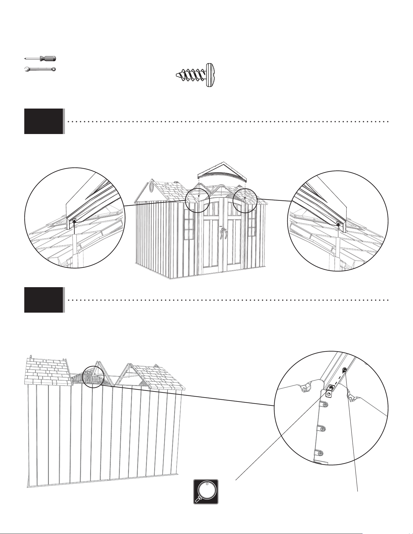
71
TOOLS AND HARDWARE REQUIRED / OUTILS ET QUINCAILLERIE REQUIS / INSTRUMENTAL Y HERRAJE REQUERIDO
X SECTION 9 (CONTINUED) / SECTION 9 (SUITE) / SECCIÓN 9 (CONTINUACIÓN)
• Set the end of the center truss onto the notch in the front gable panel as shown, and secure with one (1) screw
(ADZ).
• Mettre l’extrémité de la ferme centrale dans l’encoche dans la pignon avant comme illustré, et fi xer-la à l’aide
d’une vis (ADZ).
• Meter el extremo de la cercha central en la muesca en la fachada delantera como se muestra, y fi jarla avec un
tornillo (ADZ).
ADZ (x1)
3/8 in/po
(≈10 mm)
• Slide the holes in the entry gable down over the two hinge tubes. The ends of the gable go in the trusses.
• Faire glisser les trous dans le pignon d’entrée sur les deux tubes. Les extrémités du pignon vont dans les fermes.
• Deslizar los agujeros en la fachada de entrada sobre los dos tubos. Los extremos de la fachada van dentro de las cerchas.
8.13
8.14
• Tighten this nut and bolt now.
• Serrer ce boulon et l’écrou maintenant.
• Apretar este perno y la tuerca ahora.
ADZ
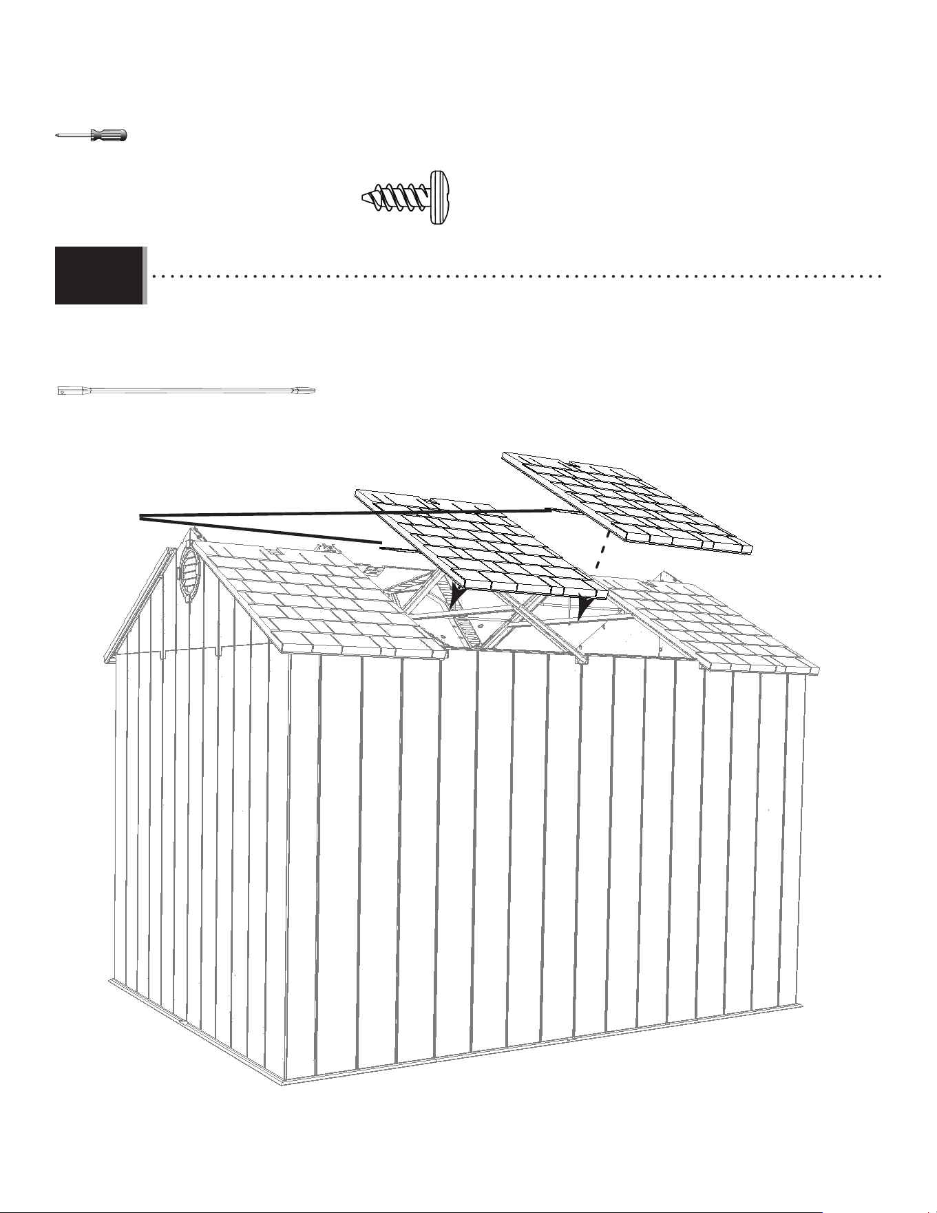
72
TOOLS AND HARDWARE REQUIRED / OUTILS ET QUINCAILLERIE REQUIS / INSTRUMENTAL Y HERRAJE REQUERIDO
X SECTION 9 (CONTINUED) / SECTION 9 (SUITE) / SECCIÓN 9 (CONTINUACIÓN)
ADZ (x20)
AGQ
AGQ
• Attach the two center, rear roof panels using only one roof support per panel.
• Fixer les deux panneaux de toit arrières centraux en utilisant un seul support de toit pour chaque panneau.
• Fijar los dos paneles de tejado traseros centrales usando sólo un Soporte de tejado por panel.
AFL (x2)
AFL
8.15
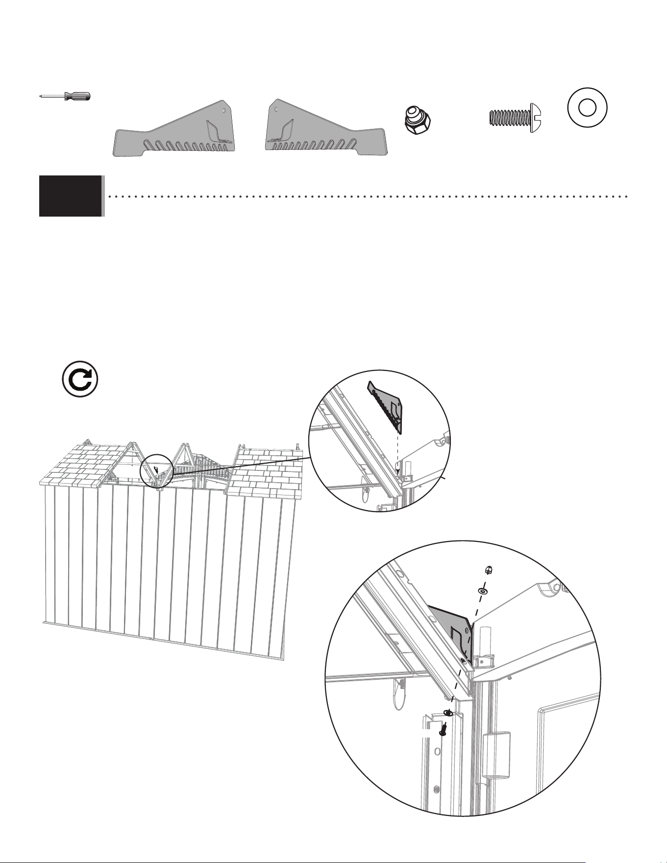
73
TOOLS AND HARDWARE REQUIRED / OUTILS ET QUINCAILLERIE REQUIS / INSTRUMENTAL Y HERRAJE REQUERIDO
X SECTION 9 (CONTINUED) / SECTION 9 (SUITE) / SECCIÓN 9 (CONTINUACIÓN)
8.16
• Insert the right drainage plate (ECS) into the right lateral truss, and align the notch in the plate with the fi rst hole in
the truss as shown. Secure with the hardware provided. Only tighten by hand for now.
• Insérer la plaque de drainage droite (ECS) dans la ferme latérale droite, et aligner l’encoche dans la plaque avec la
premier trous dans la ferme comme indiqué. Bien la fi xer à la ferme à l’aide de la quincaillerie incluse. Ne serrer
qu’à la main en ce moment.
• Insertar la placa derecha para el drenaje (ECS) dentro de la cercha lateral derecho, y alinear la muesca en la placa con el
primer agujero en la cercha. Fijarla a la cercha usando el herraje incluido. Apretar sólo a mano en este momento.
ECS
ADK
AEE
AEE
• Repeat this step for the left drainage plate (ECR).
• Répéter cette étape pour la plaque de drainage gauche (ECR).
• Repetir este paso para la placa izquierda para el drenaje (ECR).
BZA
ECS (x1)
ECR (x1)
ADK (x2)
BZA (x2)
AEE (x4)
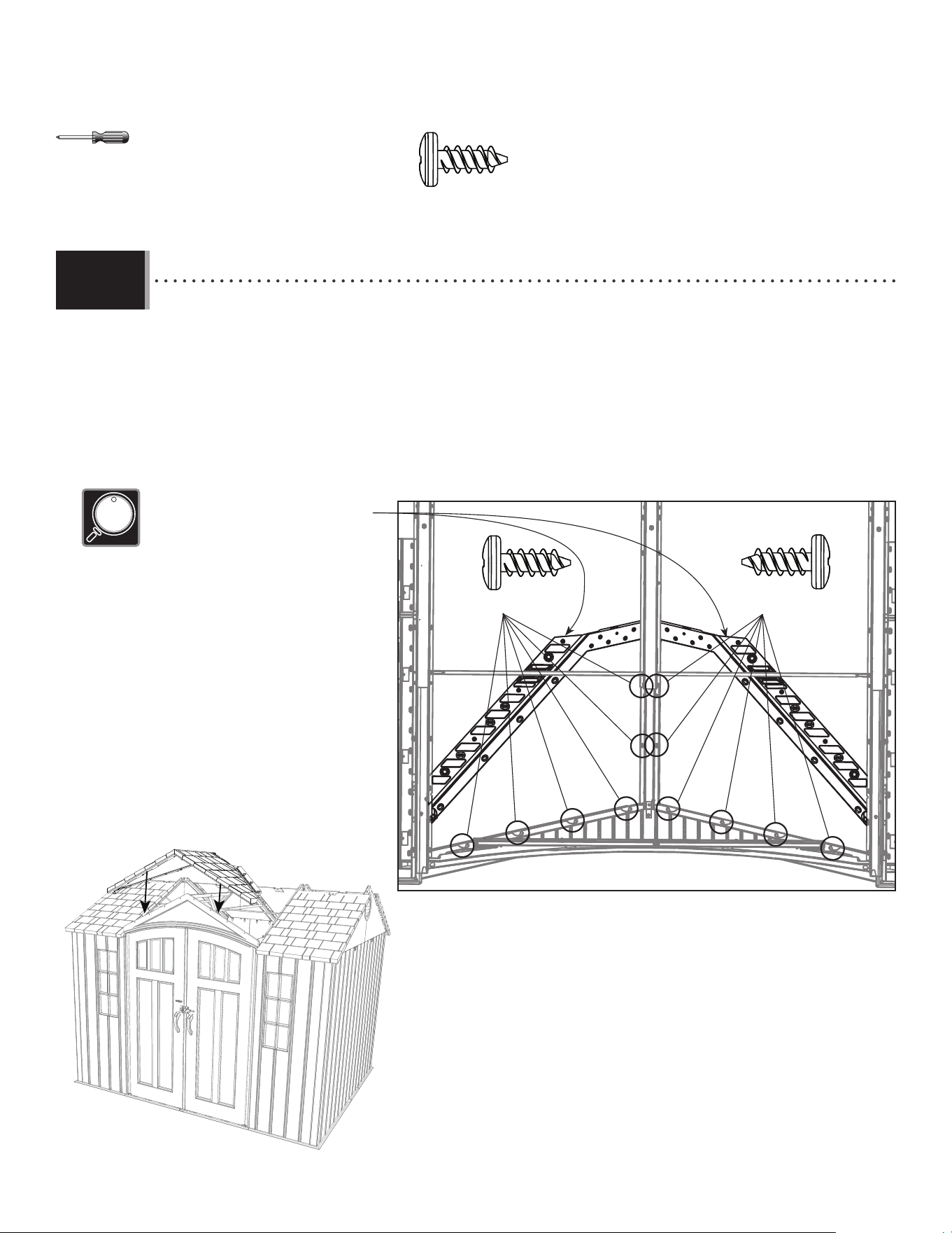
74
TOOLS AND HARDWARE REQUIRED / OUTILS ET QUINCAILLERIE REQUIS / INSTRUMENTAL Y HERRAJE REQUERIDO
X SECTION 9 (CONTINUED) / SECTION 9 (SUITE) / SECCIÓN 9 (CONTINUACIÓN)
DRA
ADZ (x6)ADZ (x6)
• Fold the ends of the large angled roof panel (DRA), and set it down onto the shed as shown. Secure the panel to the
entry gable and center truss with twelve (12) screws (ADZ) at the locations shown.
• Plier les extrémités du panneau de toit angulaire grand (DRA), et le mettre sur l’abri comme indiqué. Bien le fi xer au
pignon et à la ferme centrale à l’aide de douze (12) vis (ADZ) aux endroits indiqués.
• Doblar los extremos del panel de tejado angular grande (DRA), y colocarlo en la caseta como se muestra. Fijarlo a la
fachada y la cercha central usando doce (12) tornillos (ADZ) a las ubicaciones indicadas.
• Fold these ends upward before installing.
• Plier ces rabats en haut avant d’installer.
• Doblar estas solapas hacia arriba antes de instalar.
ADZ (x12)
8.17
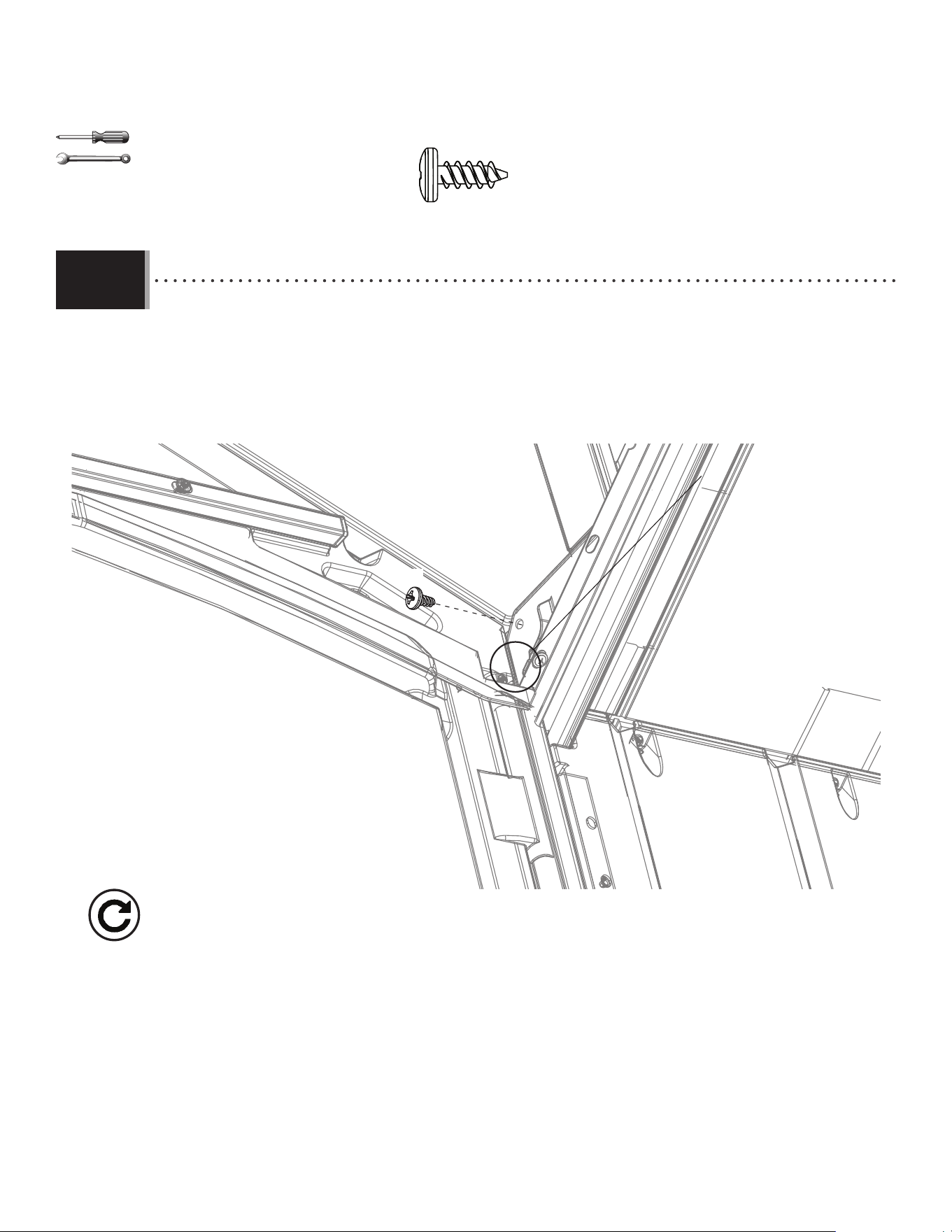
75
TOOLS AND HARDWARE REQUIRED / OUTILS ET QUINCAILLERIE REQUIS / INSTRUMENTAL Y HERRAJE REQUERIDO
X SECTION 9 (CONTINUED) / SECTION 9 (SUITE) / SECCIÓN 9 (CONTINUACIÓN)
• Secure the drainage plates from step 8.16 to the roof at the location shown. Tighten the nut on the drainage
plate now.
• Fixer les plaques de drainage des étapes 8.16 au toit à l’endroit indiqué. Serrer l’écrou dans la plaque de
drainage.
• Fijar las placas de drenaje de los pasos 8.16 al tejado a la ubicación indicada. Apretar la tuerca en la placa
de drenaje ahora.
ADZ
8.18
• Repeat this step for the other drainage plate.
• Répéter cette étape pour l’autre plaque de drainage.
• Repetir este paso para la otra placa de drenaje.
3/8 in/po
(≈10 mm)
ADZ (x2)
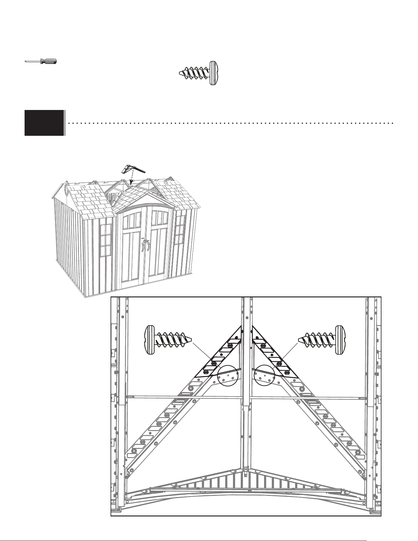
76
TOOLS AND HARDWARE REQUIRED / OUTILS ET QUINCAILLERIE REQUIS / INSTRUMENTAL Y HERRAJE REQUERIDO
X SECTION 9 (CONTINUED) / SECTION 9 (SUITE) / SECCIÓN 9 (CONTINUACIÓN)
• An adult must apply a downward pressure on panel (DRB) during the insertion of the screws (ADZ).
• Une adulte doit appliquer pression sur le panneau (DRB) pendant l’insertion des vis (ADZ).
• Un adulto debe aplicar una presión de arriba en el panel (DRB) durante la inserción de los tornillos (ADZ).
ADZ (x2)
ADZ (x1)
ADZ (x1)
8.19
DRB
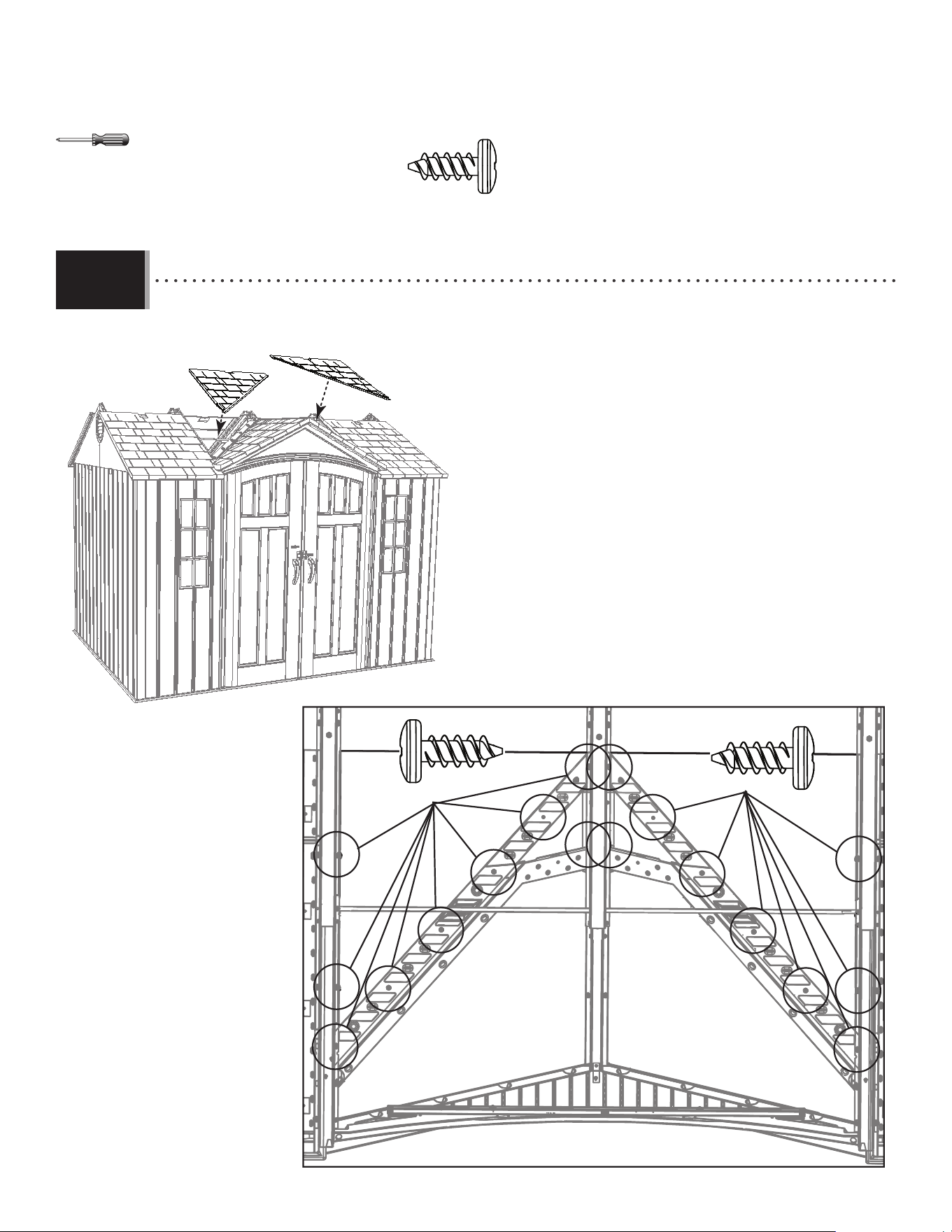
77
TOOLS AND HARDWARE REQUIRED / OUTILS ET QUINCAILLERIE REQUIS / INSTRUMENTAL Y HERRAJE REQUERIDO
X SECTION 9 (CONTINUED) / SECTION 9 (SUITE) / SECCIÓN 9 (CONTINUACIÓN)
8.20
BDR
BDS
ADZ (x9)
ADZ (x9)
• An adult must apply a downward pressure on panels (BDS & BDR) during the insertion of the screws (ADZ).
• Une adulte doit appliquer pression sur les panneaux (BDS et BDR) pendant l’insertion des vis (ADZ).
• Un adulto debe aplicar una presión de arriba en los paneles (BDS y BDR) durante la inserción de los tornillos (ADZ).
ADZ (x18)
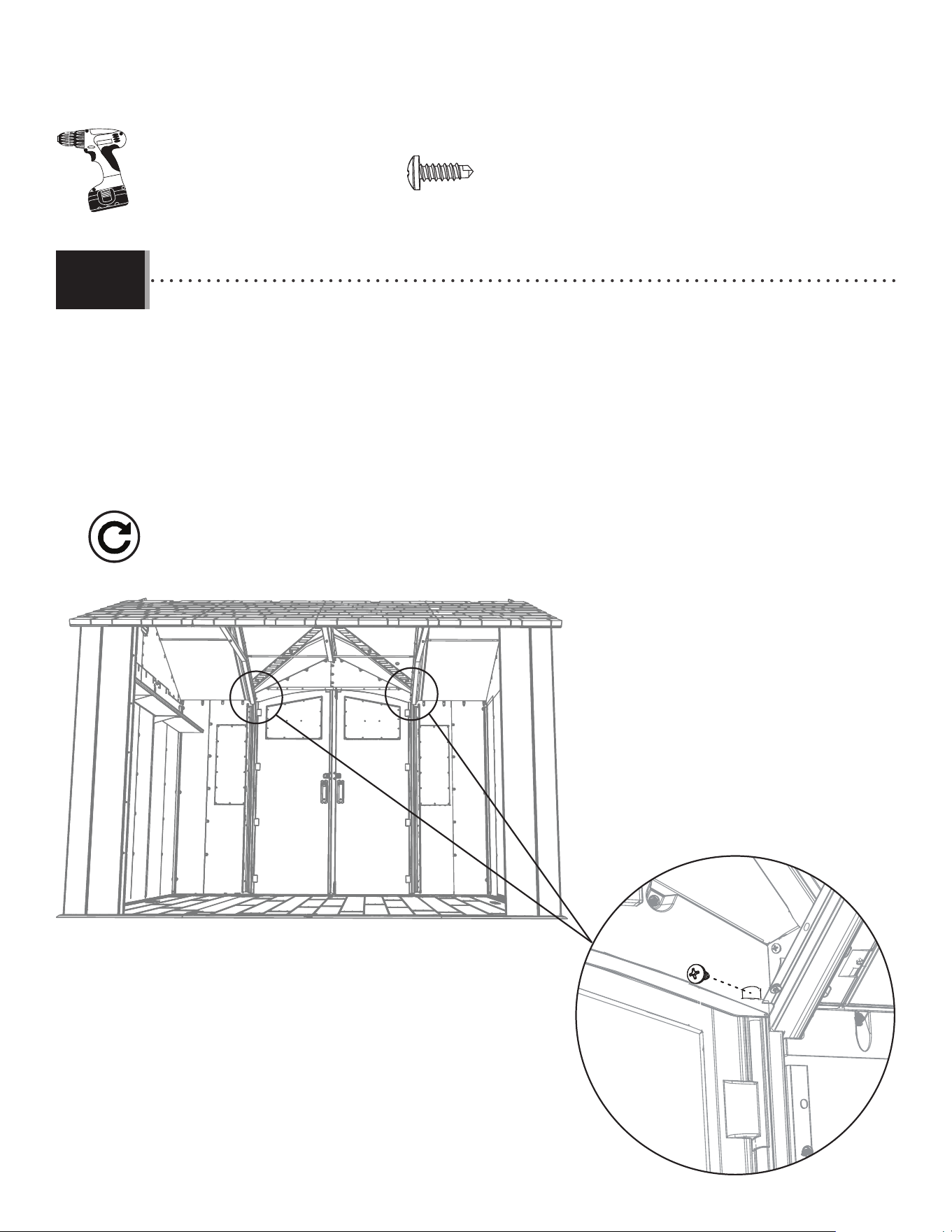
78
TOOLS AND HARDWARE REQUIRED / OUTILS ET QUINCAILLERIE REQUIS / INSTRUMENTAL Y HERRAJE REQUERIDO
X SECTION 9 (CONTINUED) / SECTION 9 (SUITE) / SECCIÓN 9 (CONTINUACIÓN)
BHJ (x2)
BHJ
• Use an electric screwdriver to Insert a self-tapping screw (BHJ) through the plastic of the gable and into the door
hinge tube at the location shown.
• Employer un perceuse électrique pour insérer une vis autotaraudeuse (BHJ) à travers le pignon et dans la charnière de
la porte à l’endroit indiqué.
• Utilizar un taladro eléctrico para introducir un tornillo auto-roscante (BHJ) a través la fachada y dentro de la bisagra a
la ubicación indicada.
8.21
• Repeat this step for the right door.
• Répéter cette étape pour la porte droite.
• Repetir este paso para la puerta derecha.
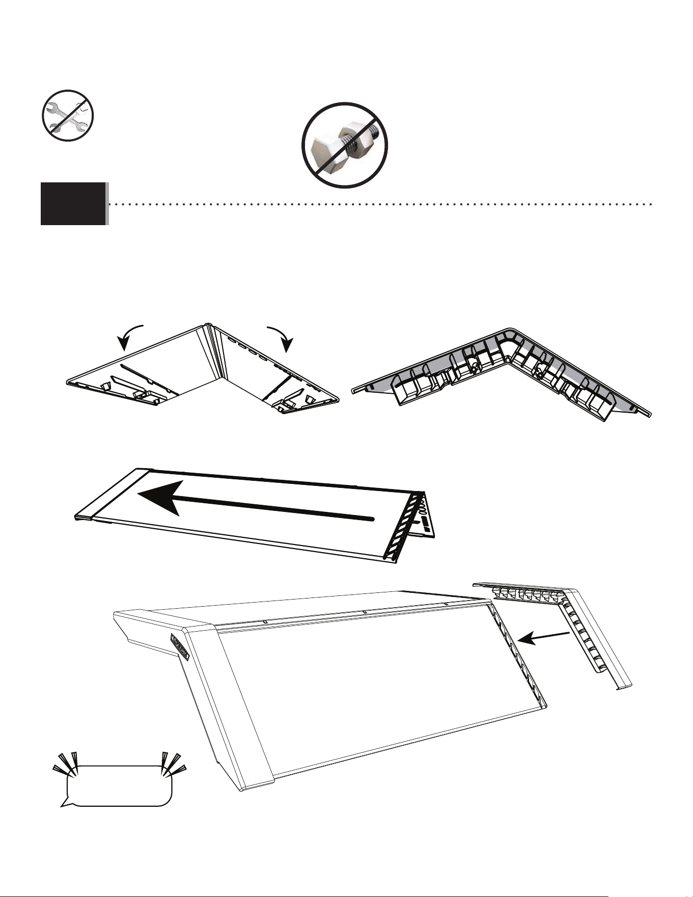
79
TOOLS AND HARDWARE REQUIRED / OUTILS ET QUINCAILLERIE REQUIS / INSTRUMENTAL Y HERRAJE REQUERIDO
X SECTION 9 (CONTINUED) / SECTION 9 (SUITE) / SECCIÓN 9 (CONTINUACIÓN)
• Bend the skylights (HLF) slighty before installing them. The fi rst skylight will fi t in the upper edge of the end cap (HOC).
Place a connector (HOB) on the other end of the skylight, fi tting it into the upper edge.
• Plier les puits de lumière (HLF) légèrement avant de les installer. Le premier puits de lumière s’insère dans le
bord supérieur du capuchon (HOC). Ensuite, mettre un connecteur (HOB) sur l’autre extrémité du puits de lumière en
l’insérant dans le bord supérieur.
• Doblar los tragaluces (HLF) ligeramente antes de instalarlos. El primer tragaluz se encajará en el borde superior del
tapón (HOC). Colocar un conector (HOB) en el otro extremo del tragaluz, encajándolo en el borde superior.
8.22
HLF
HOC
HLFHOC
HOB
• The skylights, end caps and connectors are designed to be a very snug fi t. It will take some e ort to get them installed.
• Les puits de lumière, capuchons et connecteurs sont conçus pour un bon ajustement. Il faudra un certain e ort pour les installer.
• Los tragaluces, tapones y conectores están diseñados para un ajuste preciso. Requerirá cierto esfuerzo para instalarlos.
“$#@*%!”
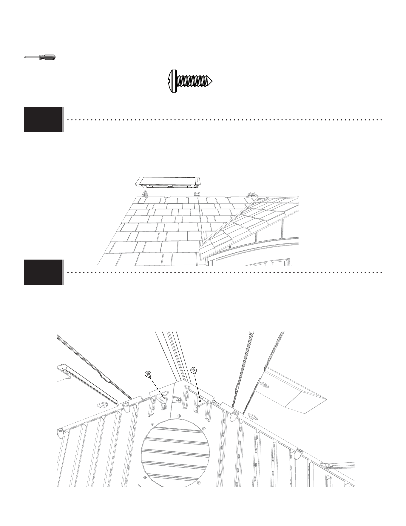
80
TOOLS AND HARDWARE REQUIRED / OUTILS ET QUINCAILLERIE REQUIS / INSTRUMENTAL Y HERRAJE REQUERIDO
X SECTION 9 (CONTINUED) / SECTION 9 (SUITE) / SECCIÓN 9 (CONTINUACIÓN)
• Place the skylight onto the end of the roof. Fit the end cap over the gable. The end of the connector will extend to
the truss.
• Mettre le puits de lumière sur l’extrémité du toit. Fixer le capuchon sur le toit à pignon. L’extrémité du
connecteur s’étendra à la ferme.
• Colocar el tragaluz sobre el extremo del techo. Fijar bien el tapón sobre la fachada. El extremo del conector se
extenderá a la cercha.
8.23
• While another adult puts pressure on the end cap outside the shed, attach the end cap to the inside of the shed
using the hardware indicated.
• Pendant q’un autre adulte met pression sur le capuchon à l’extérieur de l’abri, fi xer le capuchon à l’intérieur de
l’abri en utilisant la quincaillerie indiquée.
• Mientras otro adulto ejerce presión sobre el tapón fuera de la caseta, fi jar el tapón al interior de la caseta usando
el herraje indicado.
8.24
ARV (x2)
ARV
ARV
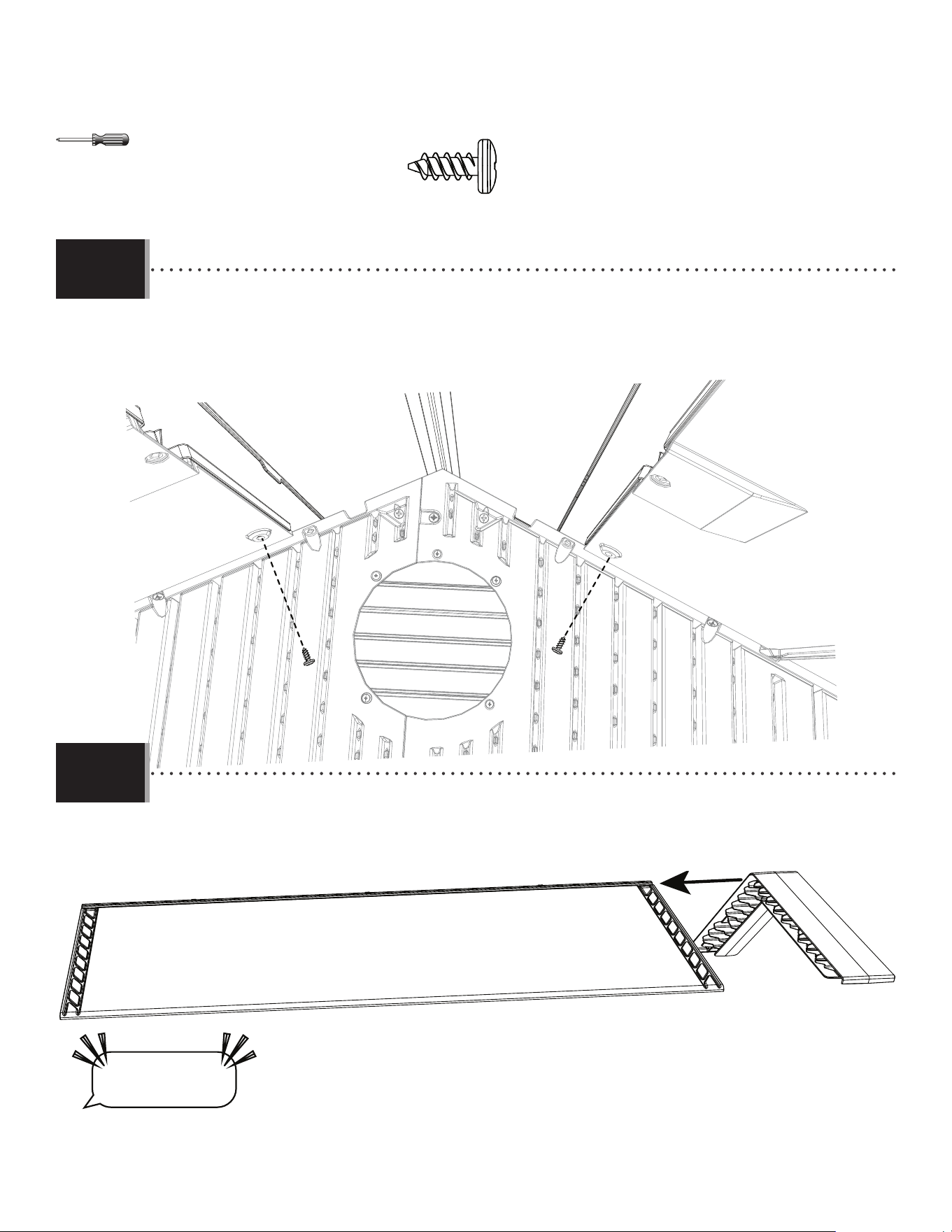
81
TOOLS AND HARDWARE REQUIRED / OUTILS ET QUINCAILLERIE REQUIS / INSTRUMENTAL Y HERRAJE REQUERIDO
X SECTION 9 (CONTINUED) / SECTION 9 (SUITE) / SECCIÓN 9 (CONTINUACIÓN)
• Secure the skylight with the hardware indicated in the location shown. Do not use any other hardware until all
the skylights are in place.
• Bien attacher le puits de lumière en utilisant la quincaillerie indiquée à l’endroit indiqué. Ne pas utiliser toute
autre quincaillerie jusqu’à ce que tous les autres puits de lumière soient en place.
• Fijar bien el tragaluz usando el herraje indicado a la ubicación indicada. No usar ningún otro herraje hasta que
todos los tragaluces estén en su lugar.
8.25
ADZ (x2)
ADZ
ADZ
• Place a connector on the end of the 2nd skylight.
• Mettre un connecteur sur l’extrémité du 2e puits de lumière.
• Colocar un conector en el extremo del 2° tragaluz.
8.26
• The skylights, end caps and connectors are designed to be a very snug fi t. It will take some e ort to get them installed.
• Les puits de lumière, capuchons et connecteurs sont conçus pour un bon ajustement. Il faudra un certain e ort pour les installer.
• Los tragaluces, tapones y conectores están diseñados para un ajuste preciso. Requerirá cierto esfuerzo para instalarlos.
“$#@*%!”
HOB
HLF
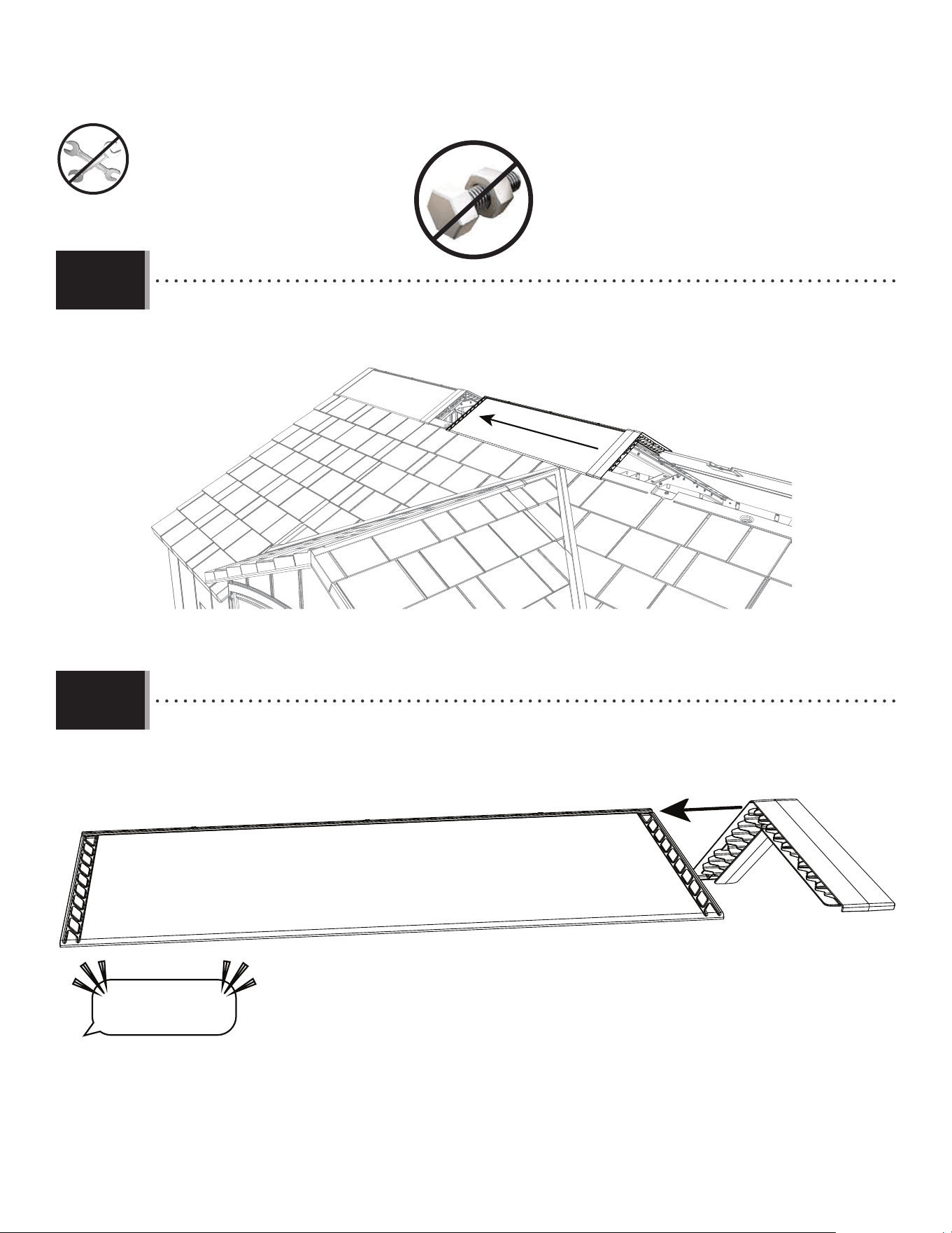
82
TOOLS AND HARDWARE REQUIRED / OUTILS ET QUINCAILLERIE REQUIS / INSTRUMENTAL Y HERRAJE REQUERIDO
X SECTION 9 (CONTINUED) / SECTION 9 (SUITE) / SECCIÓN 9 (CONTINUACIÓN)
• Place the second skylight into the upper section of the connector.
• Mettre le deuxième puits de lumière dedans la section supérieure du connecteur.
• Colocar el segundo tragaluz en la sección superior del conector.
8.27
8.28
HLF
• Place a connector on the end of the 3rd skylight.
• Mettre un connecteur sur l’extrémité du 3e puits de lumière.
• Colocar un conector en el extremo del 3° tragaluz.
• The skylights, end caps and connectors are designed to be a very snug fi t. It will take some e ort to get them installed.
• Les puits de lumière, capuchons et connecteurs sont conçus pour un bon ajustement. Il faudra un certain e ort pour les installer.
• Los tragaluces, tapones y conectores están diseñados para un ajuste preciso. Requerirá cierto esfuerzo para instalarlos.
“$#@*%!”
HLF
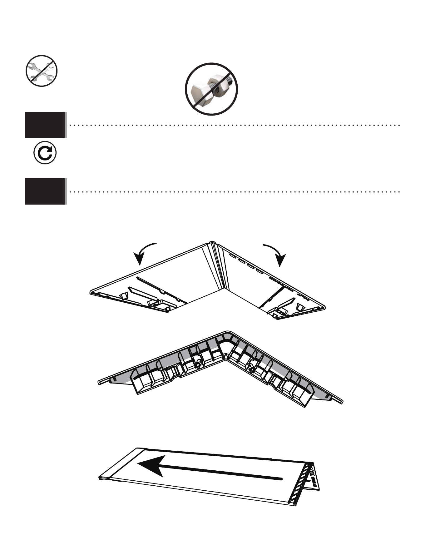
83
TOOLS AND HARDWARE REQUIRED / OUTILS ET QUINCAILLERIE REQUIS / INSTRUMENTAL Y HERRAJE REQUERIDO
X SECTION 9 (CONTINUED) / SECTION 9 (SUITE) / SECCIÓN 9 (CONTINUACIÓN)
• Repeat step 8.27 & 8.28 to add the third skylight and connector.
• Répéter l’étape 8.27 & 8.28 pour ajouter le troisième puits de lumière et connecteur.
• Repetir el paso 8.27 & 8.28 para añadir el tercer tragaluz y conector.
8.29
• Connect the last skylight to the remaining end cap. Fold the skylight before inserting into the cap.
• Attacher le dernier puits de lumière au capuchon restant. Plier le puits de lumière avant d’insérer le capuchon.
• Fijar el último tragaluz al tapón restante. Doblar el tragaluz antes de insertarlo en el tapón.
8.30
HLF
HOC
HLFHOC
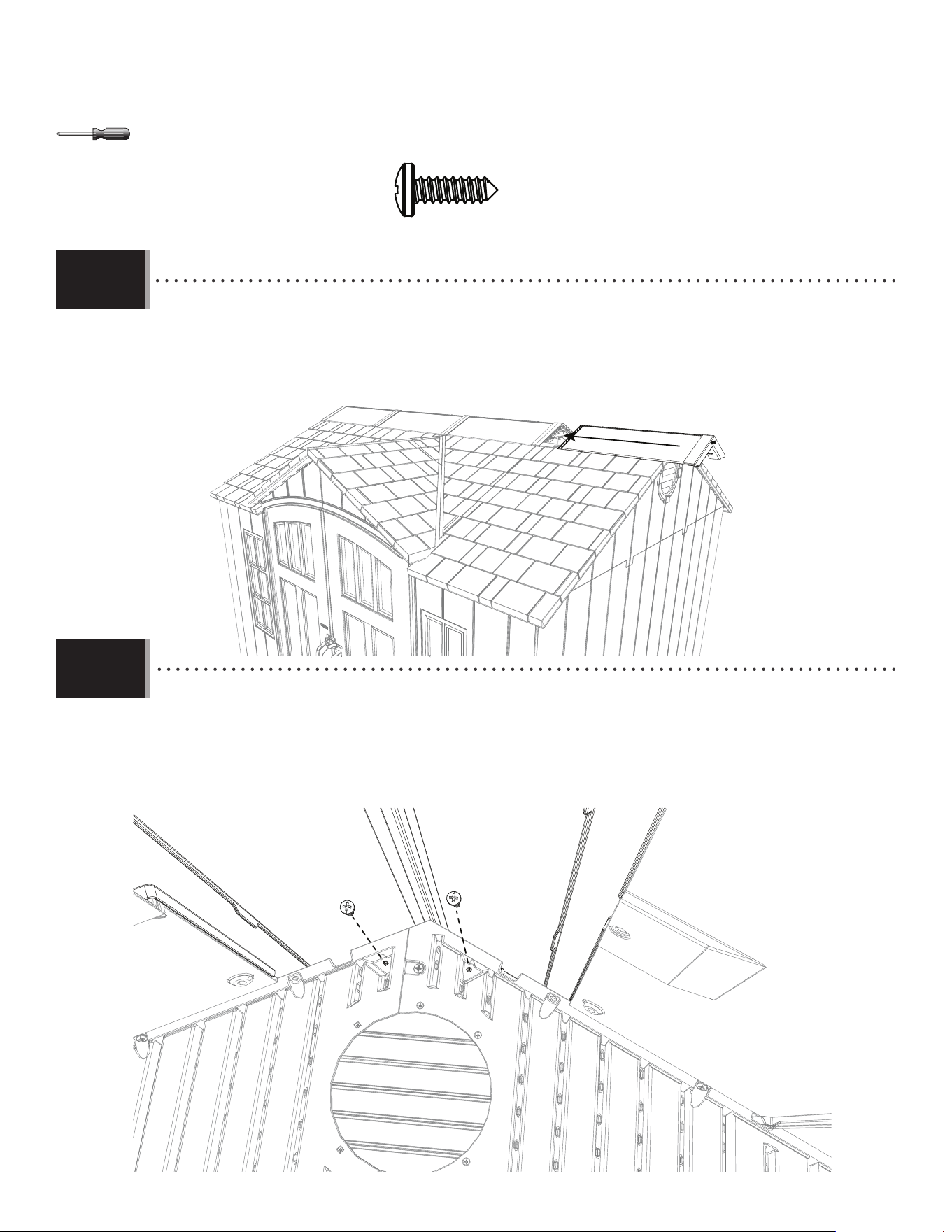
84
TOOLS AND HARDWARE REQUIRED / OUTILS ET QUINCAILLERIE REQUIS / INSTRUMENTAL Y HERRAJE REQUERIDO
X SECTION 9 (CONTINUED) / SECTION 9 (SUITE) / SECCIÓN 9 (CONTINUACIÓN)
8.31
• Place the end cap and skylight onto the end of the roof. Fit the end cap over the gable. The end of the skylight
will extend slightly past the truss.
• Mettre le capuchon y puits de lumière sur l’extrémité du toit. Fixer le capuchon sur le toit à pignon. L’extrémité
du puits de lumière s’étendra ligèrement au-delà de la ferme.
• Colocar el tragaluz sobre el extremo del techo. Fijar bien el tapón sobre la fachada. El extremo del conector se
extenderá ligeraments más allá de la cercha.
• While another adult puts pressure on the end cap outside the shed, attach the end cap to the inside of the shed
using the hardware indicated.
• Pendant q’un autre adulte met pression sur le capuchon à l’extérieur de l’abri, fi xer le capuchon à l’intérieur de
l’abri en utilisant la quincaillerie indiquée.
• Mientras otro adulto ejerce presión sobre el tapón fuera de la caseta, fi jar el tapón al interior de la caseta usando
el herraje indicado.
8.32
ARV
ARV
ARV (x2)
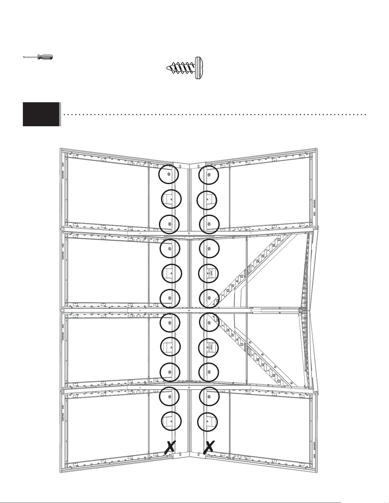
85
TOOLS AND HARDWARE REQUIRED / OUTILS ET QUINCAILLERIE REQUIS / INSTRUMENTAL Y HERRAJE REQUERIDO
X SECTION 9 (CONTINUED) / SECTION 9 (SUITE) / SECCIÓN 9 (CONTINUACIÓN)
8.33
• Attach the skylights to the roof panels with the hardware indicated.
• Attacher les puits de lumière aux panneaux de toit en utilisant la quincaillerie indiquée.
• Fijar los tragaluces a los paneles de techo usando el herraje indicado.
ADZ (x22)
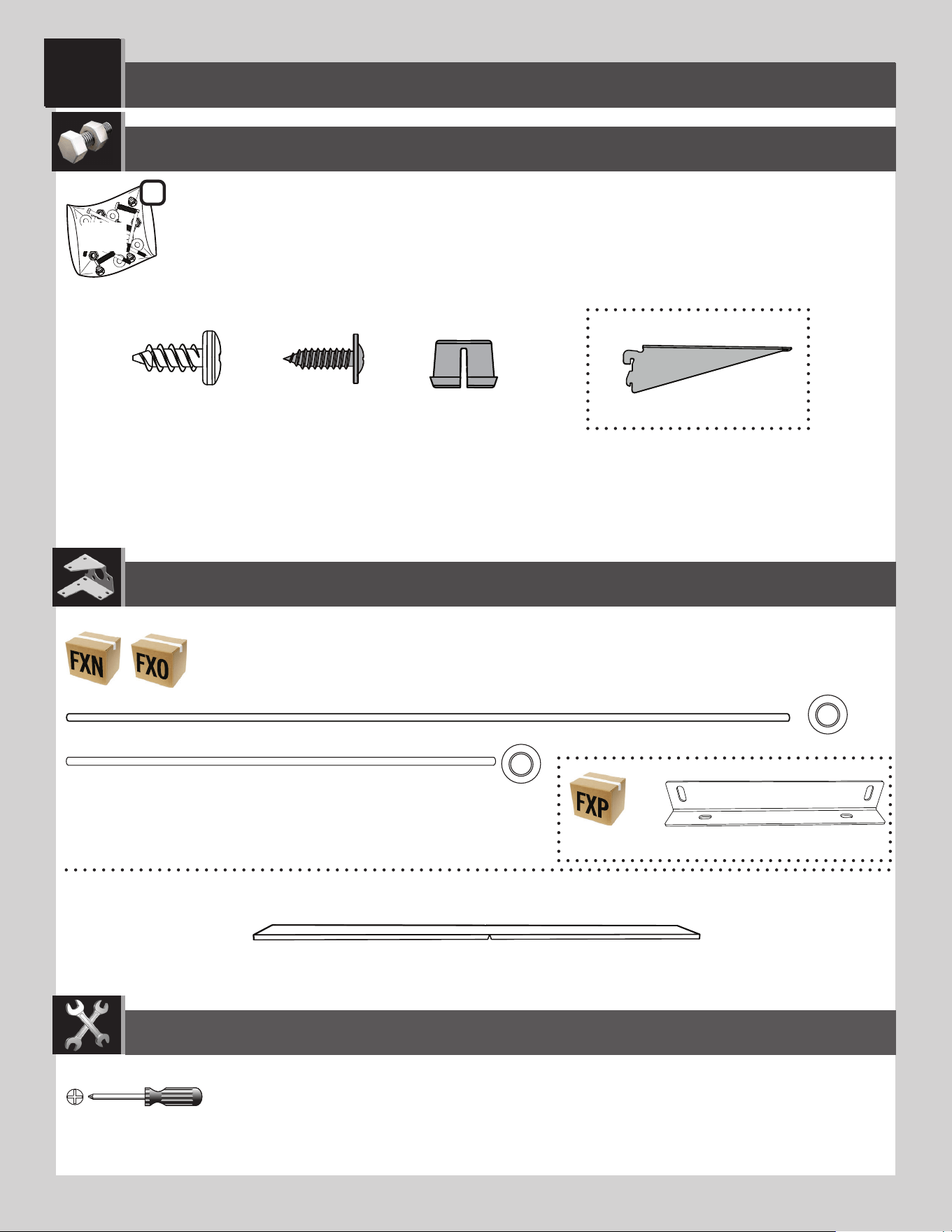
8686
SHELVING INSTALLATION / INSTALLATION DU RAYONNAGE / INSTALACIÓN DE LA ESTANTERÍA
9
AFV (x2)
Metal Parts / Pièces en métal / Piezas de metal
Plastic Parts / Pièces en plastique / Piezas de plástico
PARTS REQUIRED / PIÈCES REQUISES / PIEZAS REQUERIDAS
HARDWARE REQUIRED / QUINCAILLERIE REQUISE / HERRAJE REQUERIDO
HDU (x2)
HDT (x2)
HDV (x4)
ADZ (x32)*
AIY (x4)
HEZ
FEX (x8)
GJZ (x8)
2
Parts / Pièces / Piezas
* Not all hardware will be used in the section.
* La quincaillerie n’est pas utilisée au complet dans la section.
* No se utilizará todo el herraje en la sección.
TOOLS REQUIRED / OUTILS REQUIS / INSTRUMENTAL REQUERIDO
(Not included—unless otherwise indicated*) / (Non inclus — sauf indication contraire*) / (No incluido, salvo indicación contratia*)
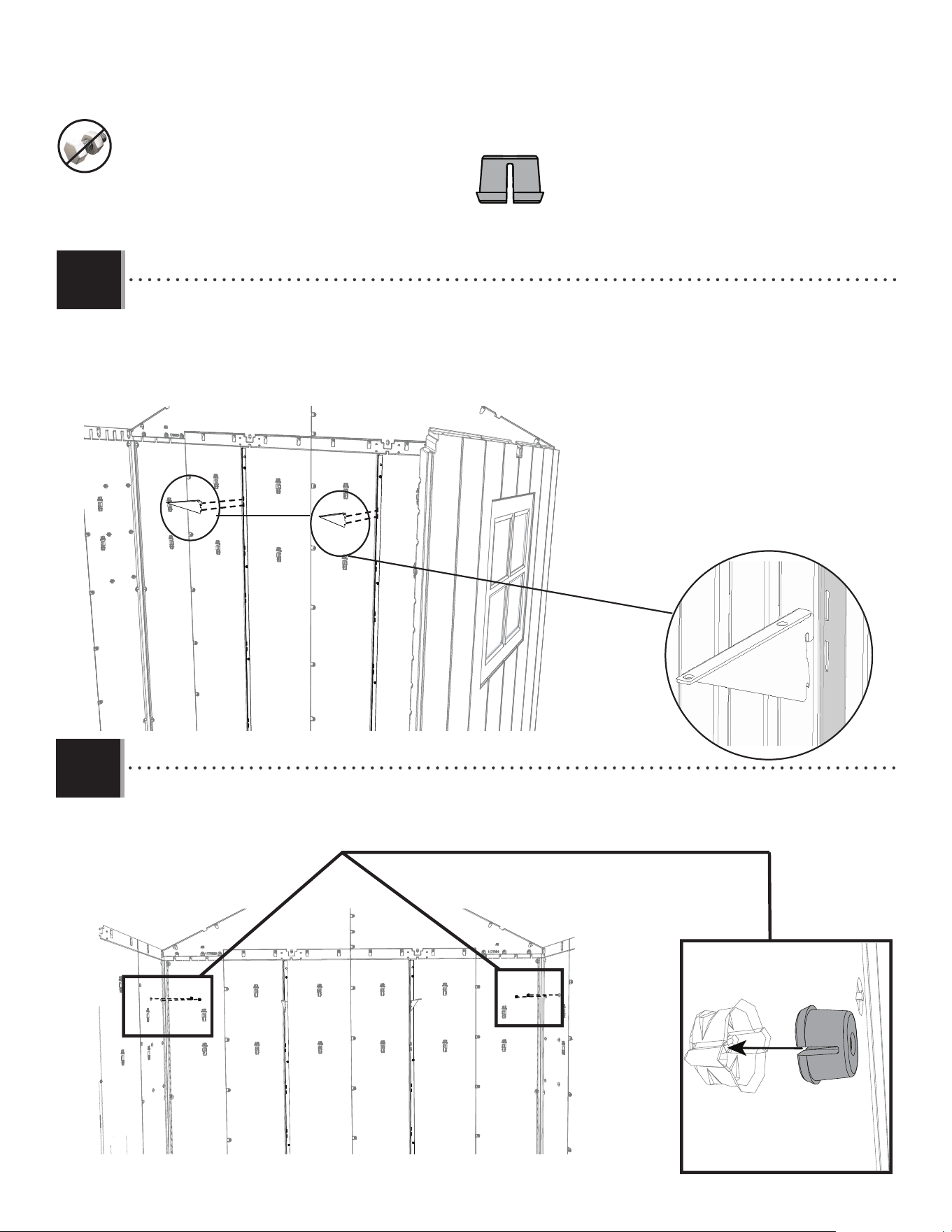
87
TOOLS AND PARTS REQUIRED / OUTILS ET QUINCAILLERIE REQUIS / INSTRUMENTAL Y HERRAJE REQUERIDOS
X SECTION 8 (CONTINUED) / SECTION 8 (SUITE) / SECCIÓN 8 (CONTINUACIÓN)
9.1
AIY
AIY
• Insert the shelf brackets (AIY) into the slots in the wall/shelf support channels. The brackets must be at the same height.
• Insérer les équerres (AIY) dans les fentes dans les cannaux de support pour les murs/étagères. Les équerres doivent être à la
même hauteur.
• Insertar las escuadras (AIY) en las rajas en los canales de soporte para las paredes/estantes. Las escuadras deben estar a la
misma altura.
9.2
• Place screw anchors (FEX) into the side walls at the same level the shelf braces were placed.
• Placez les vis d’ancrage (FEX) dans les murs de côté à la même hauteur que vous avez placé les renforts de l’étagère.
• Coloque los anclajes de tornillo (FEX) en las paredes laterales al mismo nivel en el que se colocaron los soportes del
estante.
FEX
FEX
FEX
FEX
FEX (x4)
AIY
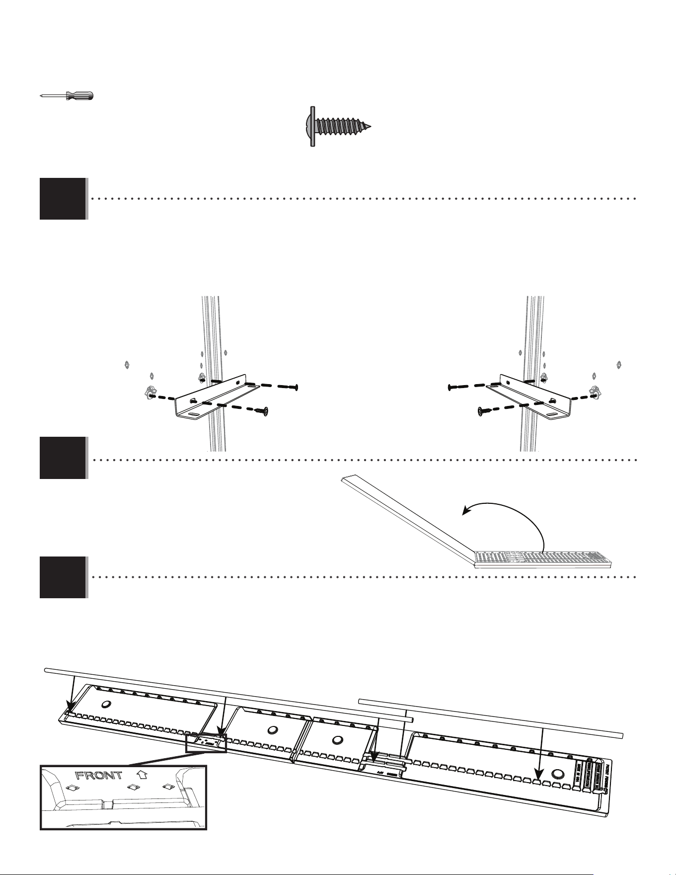
88
TOOLS AND PARTS REQUIRED / OUTILS ET QUINCAILLERIE REQUIS / INSTRUMENTAL Y HERRAJE REQUERIDOS
X SECTION 8 (CONTINUED) / SECTION 8 (SUITE) / SECCIÓN 8 (CONTINUACIÓN)
GJZ (x4)
9.3
• Attach a shelf support bracket (HDV) into the side wall at the same level the shelf brackets were placed. Repeat for the
other shelf support bracket on the opposite side.
• Placez le support de l’étagère (HDV) dans le mur de côté à la même hauteur que vous avez placé les renforts des
équerres. Répétez pour le support de l’étagère de l’autre côté.
• Fije un soporte de estante (HDV) en la pared lateral al mismo nivel en el que se colocaron las escuadras del estante.
Repita para el otro soporte de estante en el lado opuesto.
• Snap the short and long shelf support tubes (HDT and HDU) into the underside of the shelf. The long shelf support tube should
be put in place near the side labelled “Front”.
• Clipsez les tubes d’appui long et court de l’étagère (HDT et HDU) sous l’étagère. Le tube d’appui long doit être mis en place près
du côté marqué «Front».
• Conecte a presión los tubos de soporte del estante corto y largo (HDT y HDU) en la parte inferior del estante. El tubo de soporte
largo del estante debería ponerse en su lugar cerca del lado etiquetado “Front”.
9.5
HDU
• Unfold the shelf before installing.
• Dépliez l’étagère avant l’installation.
• Despliegue el estante antes de instalar.
9.4
HDT
GJZ
GJZ
HDV
GJZ
GJZ
HDV
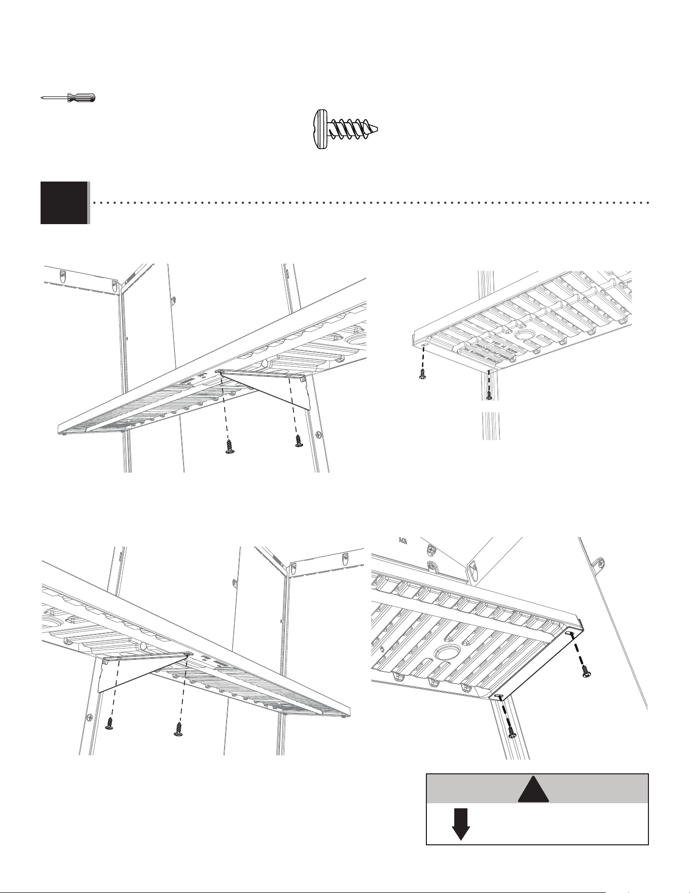
89
TOOLS AND PARTS REQUIRED / OUTILS ET QUINCAILLERIE REQUIS / INSTRUMENTAL Y HERRAJE REQUERIDOS
X SECTION 8 (CONTINUED) / SECTION 8 (SUITE) / SECCIÓN 8 (CONTINUACIÓN)
AFV
ADZ
50 lb. (≈23 kg)
!
• Attach the shelf (AFV) to the corner wall panels and shelf support brackets using eight (8) screws (ADZ).
• Attachez l’étagère (AFV) aux panneaux de mur de coin et aux supports de l’étagère à l’aide de huit (8)vis (ADZ).
• Fije el estante (AFV) a los paneles de pared de esquina y a los soportes del estante usando ocho (8) tornillos (ADZ).
9.6
ADZ
ADZ (x8)
AFV
ADZ
ADZ
ADZ
ADZ
ADZ
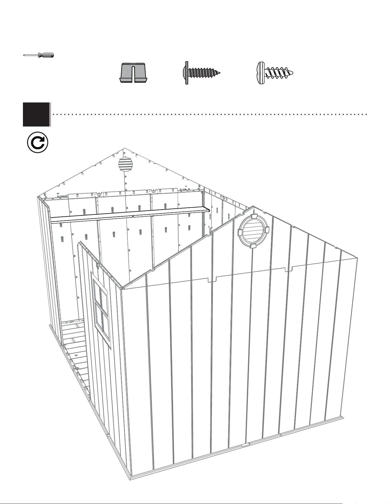
90
TOOLS AND PARTS REQUIRED / OUTILS ET QUINCAILLERIE REQUIS / INSTRUMENTAL Y HERRAJE REQUERIDOS
X SECTION 8 (CONTINUED) / SECTION 8 (SUITE) / SECCIÓN 8 (CONTINUACIÓN)
9.7
FEX (x4)
GJZ (x4)
ADZ (x16)
• Repeat steps 9.1–9.6 to install the second shelf on the opposite wall.
• Répétez les étapes 9.1 – 9.6 pour installer le deuxième étagère sur le mur opposé.
• Repita los pasos 9.1–9.6 para instalar el segundo estante en el muro opuesto.
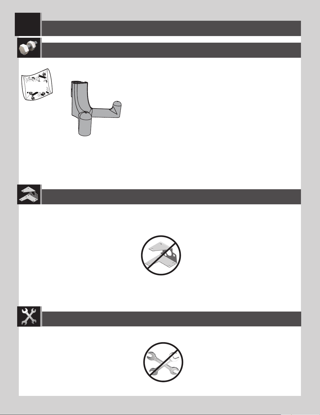
9191
WALL HOOK INSTALLATION / INSTALLATION DES CROCHETS MURAUX / INSTALACIÓN DE LOS GANCHOS MURALES
10
PARTS REQUIRED / PIÈCES REQUISES / PIEZAS REQUERIDAS
HARDWARE REQUIRED / QUINCAILLERIE REQUISE / HERRAJE REQUERIDO
EDH
EDL (x6)
TOOLS REQUIRED / OUTILS REQUIS / INSTRUMENTAL REQUERIDO
(Not included—unless otherwise indicated*) / (Non inclus — sauf indication contraire*) / (No incluido, salvo indicación contraria*)
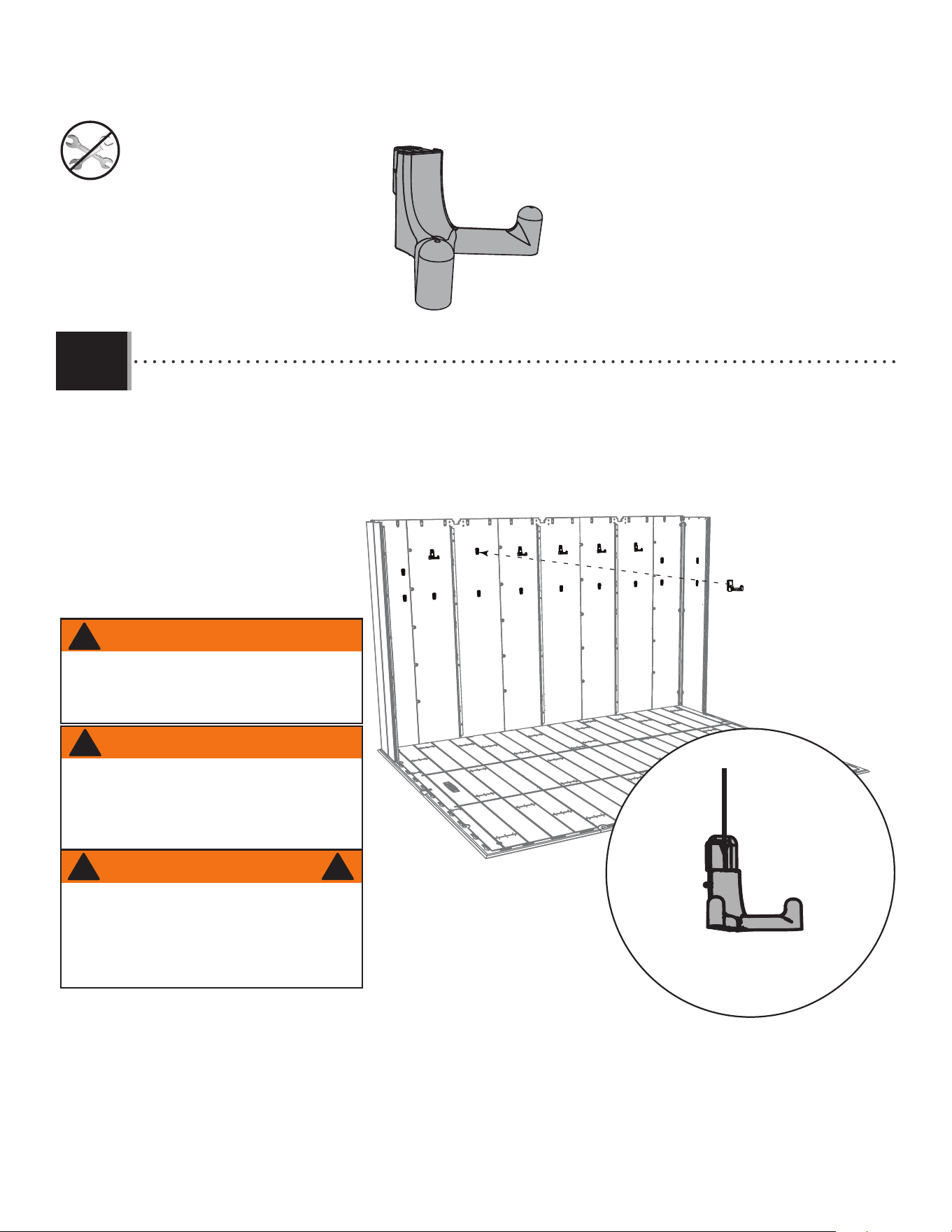
92
TOOLS AND HARDWARE REQUIRED / OUTILS ET QUINCAILLERIE REQUIS / INSTRUMENTAL Y HERRAJE REQUERIDOS
X SECTION 10 (CONTINUED) / SECTION 10 (SUITE) / SECCIÓN 10 (CONTINUACIÓN)
• Insert the six (6) wall hooks (EDL) into any of the notches in the wall panels. Then push downward to lock them in
place.
• Insérer les six (6) crochets muraux (EDL) dans les encoches dans les panneaux muraux. Ensuite, les pousser vers le bas
pour bien les attacher en place.
• Insertar los seis (6) ganchos murales (EDL) en las muescas en los paneles murales. Entonces, empujarlos hacia abajo
para fi jarlos bien en su lugar.
10.1
EDL (x6)
EDL
WARNING
The total weight on a wall hook should not exceed
≈3.2 kg (7 lb) nor more than ≈14 kg (30 lb) on a
wall panel. Failure to follow this warning could result
in property damage and/or personal injury.
!
ADVERTENCIA
El peso total en un gancho mural no debe
exceder de 7 lb (3.2 kg) ni más de 30 lb
(14 kg) en un panel mural. El no seguir esta
advertencia puede resultar en daños a la
propiedad y/o en lesiones graves personales.
!
!
AVERTISSEMENT
Le poids total sur un crochet mural ne devrait
pas excéder ≈3,2 kg (7 lb) ou plus de ≈14 kg (30
lb) sur un panneau mural. Le non-respect de cet
avertissement peut entrainer des dommages à la
propriété et/ou des blessures graves.
!
EDL
9393
DOOR ALIGNMENT / ALIGNEMENT DES PORTES / ALINEACIÓN DE LAS PUERTAS
11
PARTS REQUIRED / PIÈCES REQUISES / PIEZAS REQUERIDAS
HARDWARE REQUIRED / QUINCAILLERIE REQUISE / HERRAJE REQUERIDO
AIX (x4)
Plastic parts / Pièces en plastique / Piezas de plástico
TOOLS REQUIRED / OUTILS REQUIS / INSTRUMENTAL REQUERIDO
(Not included—unless otherwise indicated*) / (Non inclus — sauf indication contraire*) / (No incluido, salvo indicación contratia*)
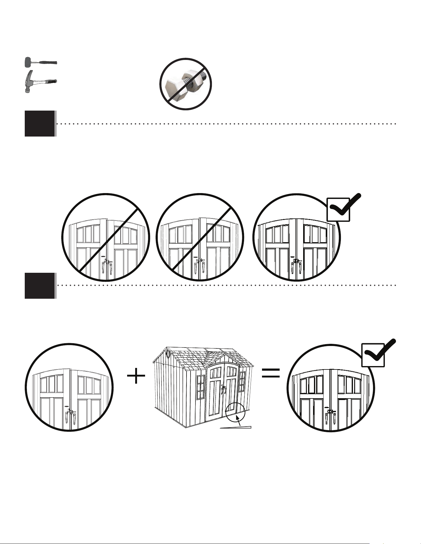
94
X SECTION 11 (CONTINUED) / SECTION 11 (SUITE) / SECCIÓN 11 (CONTINUACIÓN)
TOOLS AND HARDWARE REQUIRED / OUTILS ET QUINCAILLERIE REQUIS / INSTRUMENTAL Y HERRAJE REQUERIDOS
Fig. 1
Fig. 2
AIX
Fig. 3
• If the doors are not level, follow the steps on this page or the next to even them out.
• Si les portes ne sont pas niveaux l’une avec l’autre, suivre les étapes dans cette page ou la suivante pour les niveler.
• Si las puertas no están niveladas, seguir los pasos en esta página o la siguiente para nivelarlas.
• If the left door is higher, insert a shim (AIX) underneath the right, front and left, rear corners of the shed until the
doors are the same height. Break o any excess shim.
• Si la porte gauche est plus haute, insérer une cale (AIX) sous le coin avant droit jusqu’à ce que les portes restent à la
même hauteur. Détacher de l’excès des cales.
• Si la puerta izquierda es más alta, insertar una cuña (AIX) debajo las esquinas delantera derecha y trasera izquierda
hasta que las puertas queden a la misma altura. Quebrantar cualquier exceso de las cuñas.
11.1
11.2
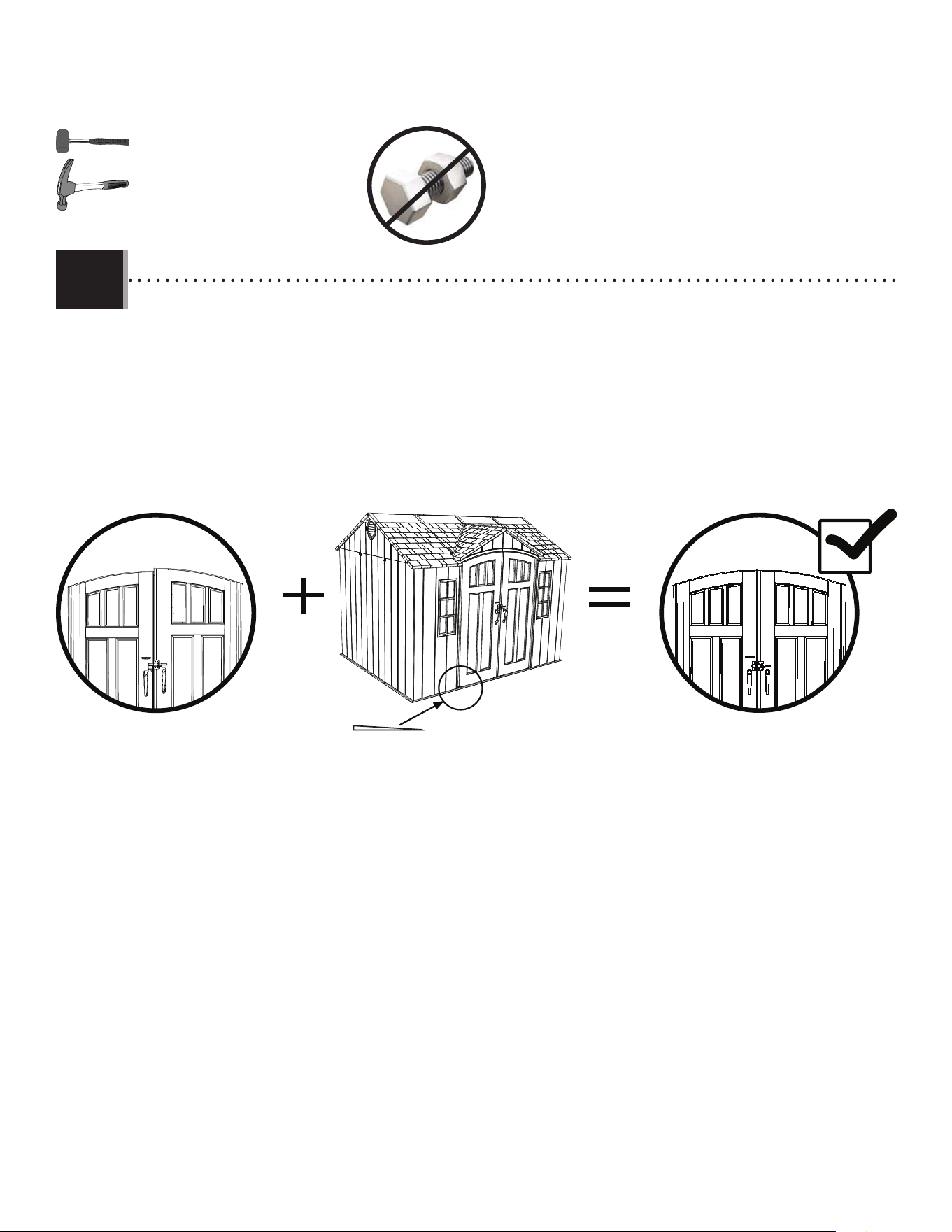
95
X SECTION 11 (CONTINUED) / SECTION 11 (SUITE) / SECCIÓN 11 (CONTINUACIÓN)
TOOLS AND HARDWARE REQUIRED / OUTILS ET QUINCAILLERIE REQUIS / INSTRUMENTAL Y HERRAJE REQUERIDOS
Fig. 1
Fig. 2
AIX
Fig. 3
• If the right door is higher, insert a shim (AIX) underneath the left, front and right, rear corners of the shed until the
doors are the same height. Break o any excess shim. Tighten all hardware now.
• Si la porte droite est plus haute, insérer une cale (AIX) sous les coins avant gauche et arrière droit jusqu’à ce que les
portes restent à la même hauteur. Détacher de l’excès des cales. Serrez bien maintenant tous les accessoires.
• Si la puerta derecha es más alta, insertar una cuña (AIX) debajo las esquinas delantera izquierda y trasera derecha
hasta que las puertas queden a la misma altura. Quebrantar cualquier exceso de las cuñas. Apriete todos los elementos ahora.
11.3
9696
SHED ANCHORING / ANCRAGE DE L’ABRI / ANCLAJE DE LA CASETA
PARTS REQUIRED / PIÈCES REQUISES / PIEZAS REQUERIDAS
HARDWARE REQUIRED / QUINCAILLERIE REQUISE / HERRAJE REQUERIDO
12
5/16” (≈8 mm) Wood Drill Bit
Foret à boit de 5/16 po (≈8 mm)
Broca para madera de 5/16 in (≈8 mm)
5/16” (≈8 mm) Masonry Drill Bit
Foret à maçonnerie de 5/16 po (≈8 mm)
Broca para albañilería de 5/16 in (≈8 mm)
TOOLS REQUIRED / OUTILS REQUIS / INSTRUMENTAL REQUERIDO
(Not included—unless otherwise indicated*) / (Non inclus — sauf indication contraire*) / (No incluido, salvo indicación contratia*)
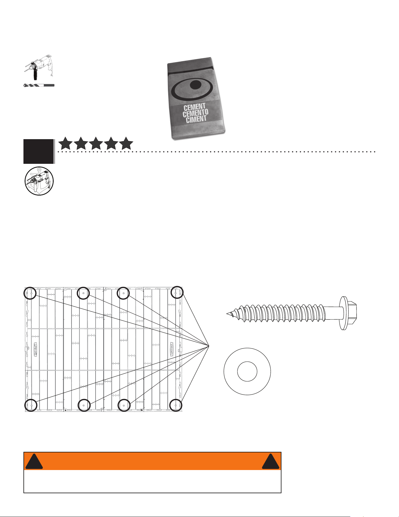
97
(x8)
(x8)
5/16 in/po
(≈8 mm)
(Not included) (No incluidos) (Pas incluses)
(Not included) (Pas incluses) (No incluidas)
• To anchor your shed, you must purchase the correct anchoring hardware. For a concrete platform, we recommend
using a hammer drill, 5/16" (≈8 mm) masonry bit, eight (8) 3/8" x 2" (≈10 mm x ≈5 cm) Concrete Screws and
eight (8) 3/8" x 1" (≈10 mm x ≈2,5 cm) Fender Washers. Do not exceed a 3/8" diameter screw. Refer to your local hardware store for this
hardware.
• Pour ancrer l’abri, il faut acheter la quincaillerie d’ancrage correcte. Pour une plate-forme en béton, nous recommandons
l’utilisation d’une perceuse de percussion, un foret à maçonnerie de 8 mm, huit (8) vis d’ancrage à béton de ≈10
mm x ≈5 cm (3/8 po x 2 po) et huit (8) rondelles de protection de ≈10 mm x ≈2,5 cm (3/8 po x 1 po). Ne pas dépasser
de diamètre de ≈10 mm (3/8 po). La quincaillerie locale aura ces accessoires.
• Para anclar la caseta, es necesario comprar el herraje de anclaje correcto. Para una plataforma de concreto,
recomendamos el uso un martillo perforador, broca de albañilería de 8 mm, ocho (8) tornillos de anclaje para
concreto de ≈10 mm x ≈5 cm (3/8 in x 2 in) y ocho (8) rondanas de protección de ≈10 mm x ≈2,5 cm (3/8 in x 1
in). No exceder un diámetro de ≈10 mm (3/8 in). Referirse a la ferretería local para obtener este herraje.
12.1
X SECTION 12 (CONTINUED) / SECCIÓN 12 (CONTINUACIÓN) / SECTION 12 (SUITE)
FOR CONCRETE PLATFORMS / POUR LES PLATE-FORMES EN BÉTON / PARA PLATAFORMAS DE CONCRETO
• Failure to anchor the shed may result in property damage and/or personal injury.
• Si vous n’ancrez pas votre abri, des dommages à la propriété et/ou des blessures peuvent en résulter.
• No anclar la caseta puede resultar en daños a la propiedad y/o en lesiones personales.
WARNING / AVERTISSEMENT / ADVERTENCIA
! !
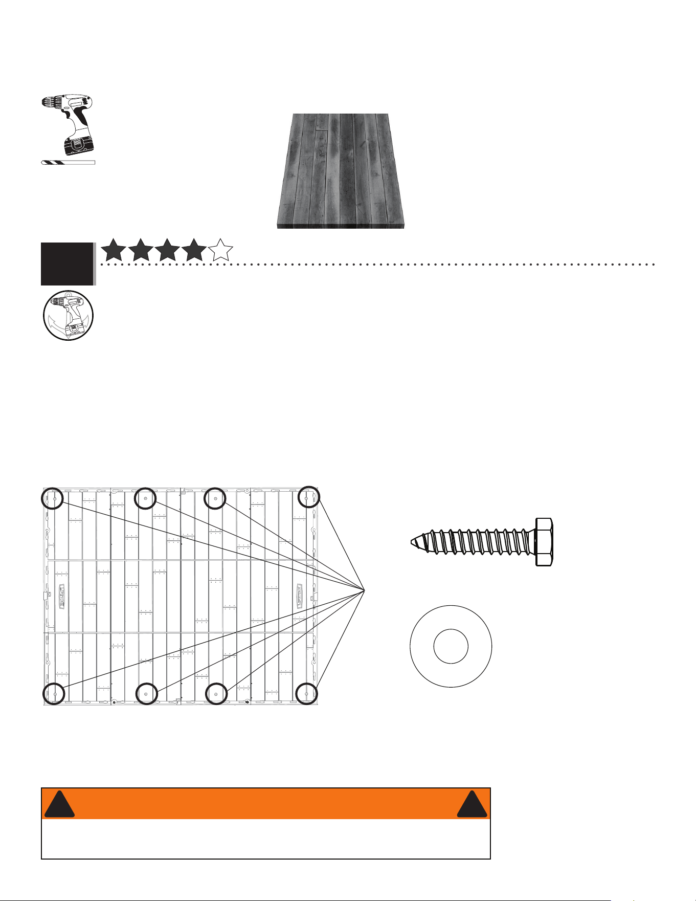
98
(x8)
(x8)
(Not included) (No incluidos) (Pas incluses)
(Not included) (Pas incluses) (No incluidas)
• To anchor your shed, you must purchase the correct anchoring hardware. For a wood-framed platform, we recommend
using a drill, 5/16" (≈8 mm) drill bit, eight (8) 3/8" x 1 1/2" (≈10 mm x ≈4 cm) Lag Screws and eight (8) 3/8" x 1"
(≈10 mm x ≈2,5 cm) Fender Washers. Do not exceed a 3/8" diameter screw. Refer to your local hardware store for this hardware.
• Pour ancrer l’abri, il faut acheter la quincaillerie d’ancrage correcte. Pour une plate-forme en bois, nous recommandons
l’utilisation d’une perceuse électrique, un foret de 8 mm, huit (8) vis de retard de ≈10 mm x ≈4 cm (3/8 po x 1
1/2 po), et huit (8) rondelles de protection de ≈10 mm x ≈2,5cm (3/8 po x 1 po). Ne pas dépasser de diamètre de ≈10 mm (3/8
po). La quincaillerie locale aura ces accessoires.
• Para anclar la caseta, es necesario comprar el herraje de anclaje correcto. Para una plataforma hecho de hecho de madera,
recomendamos el uso de un taladro eléctrico, una broca de 8 mm, ocho (8) tornillos para madera de ≈10 mm x
≈4 cm (3/8 in x 1 1/2 in) y ocho (8) rondanas de protección de ≈10 mm x ≈2,5 cm (3/8 in x 1 in). No exceda un diámetro
de ≈10 mm (3/8 in). Refi érase a su ferretería local para obtener este herraje.
12.1
X SECTION 12 (CONTINUED) / SECCIÓN 12 (CONTINUACIÓN) / SECTION 12 (SUITE)
FOR WOOD PLATFORMS / POUR LES PLATE-FORMES EN BOIS / PARA PLATAFORMAS DE MADERA
5/16 in/po
(≈8 mm)
• Failure to anchor the shed may result in property damage and/or personal injury.
• Si vous n’ancrez pas votre abri, des dommages à la propriété et/ou des blessures peuvent en résulter.
• No anclar la caseta puede resultar en daños a la propiedad y/o en lesiones personales.
WARNING / AVERTISSEMENT / ADVERTENCIA
! !

9999
Congratulations on your Lifetime
®
product purchase. By following the instructions below, your new Lifetime product should provide you with years of service and enjoyment.
The polyethylene panels are stain and solvent resistant. Most stains can be removed using a mild soap and a soft-bristled
brush. Abrasive cleaning materials may scratch the plastic and are not recommended. Repair scratches or rust spots on the
metal by sanding the a ected area lightly; using a rust preventative spray primer; and fi nally, spraying with a high-gloss spray
enamel paint. Avoid placing a direct heat source on or near surfaces unless using a heat barrier.
Nous vous félicitons d’avoir acheté ce produit Lifetime
®
. En suivant les instructions ci-dessous, votre nouveau produit Lifetime devrait vous fournir des années de service et de plaisir.
Les murs et les étagères en polyéthylène sont résistants aux taches et solvants de nettoyage. Pour les nettoyer, se servir
d’un savon doux et d’une brosse douce. Les produits abrasifs de nettoyage risquent d’égratigner le plastique et ne sont pas
recommandés. Pour réparer les égratignures ou taches de rouille sur le métal, frotter légèrement l’endroit a ecté au papier de
verre, puis passer une couche de produit vaporisant préventif, et, enfi n, vaporiser une peinture émail ultrabrillante. Éviter de
placer une source de chaleur directe sur ou près des surfaces, ou les protéger à l’aide d’une protection contre la chaleur.
CLEANING & CARE
NETTOYAGE ET ENTRETIEN
Felicidades por la compra de su producto Lifetime
®
. Al seguir las siguientes instrucciones, su nuevo producto Lifetime le brindará años de servicio y satisfacción.
Los paneles de polietileno son resistentes a las manchas y solventes. La mayoría de las manchas, pueden removerse usando
un jabón suave y un cepillo de cerdas suaves. Los materiales abrasivos para limpieza pueden rayar el plástico y no se reco-
miendan. Reparar rayones o manchas de óxido en el metal, lijando suavemente la parte afectada; usando un aerosol preven-
tivo de óxido y fi nalmente, rociando con una pintura de esmalte brillante. Evitar poner una fuente de calor directa en o cerca
de las superfi cies sin usar una barrera de calor.
LIMPIEZA Y CUIDADO

100100
LIFETIME’S PROMISE TO YOU:
We invite you to read our privacy policy at www.lifetime.com
REGISTER today!
At Lifetime
®
, we are committed to providing innovative and quality products. While registering, you will have the opportunity to give us your feedback. Your input is valuable to us.
• You can also opt in to receive new product notifi cations or promotions.
• In the unlikely event of a product recall or safety modifi cation, your registration provides the information we need to notify you directly.
• Registration is fast, easy, and completely voluntary.
Maintaining your privacy is our long-standing policy at Lifetime
®
. And you can rest assured that Lifetime
®
will not sell or provide your personal data to other third parties, or
allow them to use your personal data for their own purposes.
REGISTER YOUR PRODUCT ONLINE AT WWW.LIFETIME.COM
LA PROMESA DE LIFETIME
®
PARA USTED:
Lo invitamos a leer nuestra política de privacidad en www.lifetime.com (sólo en inglés)
¡REGISTRARSE hoy mismo!
En Lifetime
®
, estamos comprometidos a ofrecer productos innovadores y de calidad. Al registrarse, usted tendrá la oportunidad de darnos su retroalimentación. Su información es valiosa para nosotros.
• También puede optar por recibir nuestras notifi caciones o promociones.
• En el caso improbable de que el producto deba ser retirado del mercado o que sufra alguna modifi cación, su registro provee la
información que necesitamos para notifi carle directamente.
• El registro es rápido, fácil y completamente voluntario.
Mantener privacidad es nuestra política permanente en Lifetime
®
. Y puede estar seguro que Lifetime
®
no venderá ni dará datos personales a terceros, ni les permitirá usar
datos personales para sus propios fi nes.
REGISTRAR EL PRODUCTO EN LÍNEA EN WWW.LIFETIME.COM
LA PROMESSE DE LIFETIME :
Nous vous invitons à lire notre politique de confi dentialité à www.lifetime.com (en anglais seulement)
ENREGISTRER CE PRODUIT aujourd’hui!
Chez Lifetime
®
, nous nous engageons à fournir des produits innovateurs de qualité. Lors de votre inscription, vous aurez l’occasion de nous faire parvenir vos commentaires. Votre opinion est importante
pour nous.
• On peut également choisir de recevoir des avis ou des promotions dans le cadre de nouveaux produits.
• Dans l’éventualité improbable d’un rappel ou d’un avis de sécurité, l’inscription fournit les renseignements nécessaires nous
permettant de communiquer avec vous.
• L’inscription est rapide, facile et complètement volontaire.
Conserver votre confi dentialité est notre politique de longue date chez Lifetime
®
. Vous pouvez donc être rassuré par le fait que Lifetime
®
ne vendra pas ou ne fournira pas vos
données personnelles à des tiers, et ne leur permettra pas d’utiliser vos données personnelles à leurs propres fi ns.
ENREGISTRER CE PRODUIT EN LIGNE À WWW.LIFETIME.COM
LIFETIME
®
LIFETIME
®
LIFETIME
®

101101
THE MANUFACTURER RESERVES THE RIGHT TO MAKE SUBSTITUTIONS TO WARRANTY CLAIMS IF PARTS ARE UNAVAILABLE OR OBSOLETE.
10-YEAR LIMITED FACTORY WARRANTY
Lifetime Lawn and Garden products are warranted to the original purchaser to be free from defects in material or workmanship
FORAPERIODOFYEARSFROMTHEDATEOFORIGINALRETAILPURCHASE4HEWORDhDEFECTSvISDElNEDASIMPERFECTIONSTHATIMPAIR
the use of the product. Defects resulting from misuse, abuse or negligence will void this warranty. This warranty does not cover
DEFECTSDUETOIMPROPERINSTALLATIONALTERATIONORACCIDENT,IFETIMERECOMMENDSTHATNOMODIlCATIONSBEMADETOTHISPRODUCT
This warranty does not cover damage caused by vandalism, rusting, “acts of nature”, natural disasters, normal wear and tear,
or any other event beyond the control of the manufacturer.
This warranty is nontransferable and is expressly limited to the repair or replacement of defective products. If the product is
defective within the terms of this warranty, Lifetime Products, Inc. will repair or replace defective parts at no cost to the purchaser.
Shipping charges to and from the factory or distribution center are not covered and are the responsibility of the purchaser.
Labor charges and related expenses for removal, installation or replacement of the product or its components are not covered
under this warranty.
4HISWARRANTYDOESNOTCOVERSCRATCHINGSCUFlNGOROTHERCOSMETICDAMAGEOFTHEPRODUCTTHATMAYRESULTFROMNORMALUSAGE
In addition, defects resulting from intentional damage, negligence, or unreasonable use will void this warranty / are not covered
by this warranty.
Liability for incidental or consequential damages is excluded to the extent permitted by law. All merchandise is sold on this
condition, and no representative of the company may waive or change this policy. This product is not intended for institutional
or commercial use; Lifetime Products, Inc. does not assume any liability for such use. Institutional or commercial use will void
the warranty.
4HISWARRANTYISEXPRESSLYINLIEUOFALLOTHERWARRANTIESEXPRESSEDORIMPLIEDINCLUDINGWARRANTIESOFMERCHANTABILITYORlTNESS
for use to extent permitted by Federal and state law. Neither Lifetime Products, Inc., nor any representative assumes any other
LIABILITYINCONNECTIONWITHTHISPRODUCT4HISWARRANTYGIVESYOUSPECIlCLEGALRIGHTSANDYOUMAYALSOHAVEOTHERRIGHTSWHICH
vary from state to state.
AUSTRALIA : Our goods come with guarantees that cannot be excluded under the Australian Consumer Law. You are entitled
to a replacement or refund for a major failure and for compensation for any other reasonably foreseeable loss or damage. You
are also entitled to have the goods repaired or replaced if the goods fail to be of acceptable quality and the failure does not
amount to a major failure.
ALL WARRANTY CLAIMS MUST BE ACCOMPANIED BY A SALES RECEIPT.
REPORT PRODUCT DEFECTS IN WRITING TO:
LIFETIME PRODUCTS, INC.,
PO Box 160010
Freeport Center, Bldg. D-12
#LEARlELD54
For online warranty claims, please visit: www.lifetime.com/warranty
7ARRANTY$EPARTMENT
FOR INTERNATIONAL WARRANTY:
All warranty claims must be accompanied by a sales receipt. Report product defects in writing to your regional sales
support representative. Please include your dated sales receipt and photographs of damaged parts.
To Identify the representative for your region, please visit: www.lifetime.com/international

102102
LIFETIME
®
PRODUCTS, INC. RÉSERVE LE DROIT DE FAIRE DES SUBSTITUTIONS EN CAS DE RECOURS EN GARANTIE SI LES PIÈCES NE SONT PAS DISPONIBLES OU SONT
OBSOLÈTES.
GARANTIE DE FABRICATION LIMITÉE DE 10 ANS
,ACHETEURDORIGINEDESPRODUITSPOURPELOUSESETJARDINSDE,IFETIMEB¼N¼lCIEDUNEGARANTIECONTRETOUTED¼FECTUOSIT¼DE
matériel et de fabrication pour une période de 10 ans à compter de la date d’achat. On entend par « défaut » une imperfection
qui nuit à l’utilisation du produit. Tout défaut découlant d’une mauvaise utilisation, d’un abus ou d’une négligence a pour effet
d’annuler cette garantie. Cette garantie ne couvre pas les défauts attribuables à une installation inadéquate, une altération ou un
ACCIDENT,IFETIMERECOMMANDEDENEPASAPPORTERDEMODIlCATIONS¸CEPRODUIT#ETTEGARANTIENECOUVREPASLESDOMMAGES
causés par le vandalisme, la corrosion par la rouille, les cas de « force majeure », les catastrophes naturelles, la détérioration
et l’usure normales et tout autre événement indépendant de la volonté du fabricant.
Cette garantie n’est pas transférable et se limite expressément à la réparation ou au remplacement d’un produit défectueux.
Si le produit est défectueux au sens de cette garantie, Lifetime Products, Inc. réparera ou remplacera les pièces défectueuses
sans frais pour l’acheteur. Les frais d’expédition en partance ou en provenance de l’usine ou du centre de distribution ne sont
pas couverts et incombent à l’acheteur. Les coûts relatifs à la main-d’œuvre et les autres frais liés au retrait, à l’installation ou
au remplacement du produit ou de ses composants ne sont pas couverts par cette garantie.
Cette garantie ne couvre pas les rayures, les égratignures ou autres dommages esthétiques du produit découlant d’un usage
normal. De plus, tout défaut découlant d’un dommage volontaire, de négligence ou d’un usage déraisonnable annule cette
garantie et n’est pas couvert par cette garantie.
Dans la mesure permise par la loi, la société n’est pas responsable des dommages indirects ou accessoires. Toute marchandise
ESTVENDUE¸CETTECONDITIONETAUCUNREPR¼SENTANTDELASOCI¼T¼NEPEUTRENONCER¸LAPPLICATIONDECETTEPOLITIQUEOULAMODIlER
#EPRODUITNESTPASDESTIN¼¸DESlNSINSTITUTIONNELLESOUCOMMERCIALES,IFETIME0RODUCTS)NCNASSUMEAUCUNERESPONSABILIT¼
à cet égard. Toute utilisation institutionnelle ou commerciale annule la garantie.
La présente garantie remplace expressément toute autre garantie, expresse ou implicite, y compris les garanties de qualité
marchande ou d’adaptation à un usage particulier dans la mesure permise par les lois du pays ou de l’État. Ni Lifetime Products,
Inc. ni aucun de ses représentants n’assument une quelconque responsabilité en lien avec ce produit. Cette garantie vous donne
des droits juridiques précis et vous pourriez également avoir d’autres droits selon l’État ou la province.
AUSTRALIE: La garantie qui accompagne nos produits ne peut être exclue en vertu de la loi sur la protection du consommateur
de l’Australie. Le client a droit à un remplacement ou à un remboursement en cas de bris majeur et pour toute autre perte ou
dommage raisonnablement prévisible. Le client a aussi droit à ce que les produits soient réparés ou remplacés si un bris survient
ETRENDLAQUALIT¼INACCEPTABLESANSPOURAUTANT½TREQUALIlABLEDEBRISMAJEUR
TOUTE RÉCLAMATION EN VERTU DE LA GARANTIE DOIT ÊTRE ACCOMPAGNÉE D’UN REÇU DE VENTE.
SIGNALEMENT ÉCRIT DE TOUT PRODUIT DÉFECTUEUX:
LIFETIME PRODUCTS, INC.,
PO Box 160010
Freeport Center, Bldg. D-12
#LEARlELD54
Pour effectuer en ligne une réclamation sous garantie, consultez cette adresse : www.lifetime.com/warranty
3ERVICEDELAGARANTIE
GARANTIE INTERNATIONALE:
Toute réclamation en vertu de la garantie doit être accompagnée d’un reçu de vente. Veuillez signaler par écrit tout produit
défectueux au représentant du soutien aux ventes de votre région Veuillez inclure le reçu de vente daté ainsi que des
photographies des pièces endommagées.
Pour connaître le représentant de votre région, veuillez consulter le : www.lifetime.com/international

103103
EL FABRICANTE SE RESERVA EL DERECHO DE HACER SUSTITUCIONES EN LOS ELEMENTOS REEMPLAZADOS BAJO GARANTÍA SI LAS PIEZAS
NO ESTÁN DISPONIBLES O SON OBSOLETAS.
GARANTÍA DE FÁBRICA LIMITADA POR 10 AÑOS
El comprador original recibe una garantía de que los productos de césped y jardín de Lifetime están libres de defectos de material
o mano de obra durante un período de 10 años a partir de la fecha de compra original al por menor. La palabra “defectos” se
defi ne como imperfección que imposibilita el uso del producto. Los defectos ocasionados por el mal uso, el abuso o la negligencia
anularán esta garantía. Esta garantía no cubre los defectos debidos a una instalación incorrecta, una alteración o un accidente.
Lifetime recomienda que no se realicen modifi caciones en este producto. Esta garantía no cubre los daños causados por vandalismo,
oxidación, “actos de la naturaleza”, desastres naturales, desgaste normal o cualquier otro evento fuera del control del fabricante.
Esta garantía no es transferible y se limita expresamente a la reparación o reemplazo de productos defectuosos. Si el producto
resulta defectuoso dentro de los términos de esta garantía, Lifetime Products, Inc. reparará o reemplazará las piezas defectuosas
sin costo alguno para el comprador. Los gastos de envío hacia y desde la fábrica o el centro de distribución no están cubiertos y
son la responsabilidad del comprador. La mano de obra y los gastos relacionados por la remoción, la instalación o la sustitución
del producto o sus componentes no están cubiertos por esta garantía.
Esta garantía no cubre los rayones, los raspones ni otros daños superfi ciales del producto que pueden resultar del uso normal.
Asimismo, los defectos resultantes de daños intencionales, negligencia o uso indebido anularán o no están cubiertos por esta garantía.
Se excluye la responsabilidad por daños imprevistos o derivados en la medida en que lo permita la ley. Toda la mercancía se vende
bajo estas condiciones y ningún representante de la empresa puede renunciar a ni cambiar esta política. Este producto no está
destinado para uso institucional o comercial; Lifetime Products, Inc. no asume ninguna responsabilidad por dicho uso. El uso
institucional o comercial anulará la garantía.
Esta garantía sustituye expresamente cualquier otra garantía, expresa o implícita, incluidas las garantías de comercialización o
idoneidad para su uso en la medida permitida por la ley federal y estatal. Ni Lifetime Products, Inc., ni ningún representante asume
ninguna otra responsabilidad en relación con este producto. Esta garantía le otorga derechos legales específi cos y usted también
puede tener otros derechos que varían de un estado a otro.
AUSTRALIA : Nuestros productos vienen con garantías que no se pueden excluir bajo la Ley Australiana del Consumidor. Usted tiene
derecho a recibir un reemplazo o reembolso por un fallo grave y compensación por cualquier otra pérdida o daño razonablemente
previsible. También tiene derecho a la reparación o el reemplazo de los bienes si los bienes no son de calidad aceptable y el fallo
no supone un fallo grave.
TODOS LOS RECLAMOS DE GARANTÍA DEBEN ESTAR ACOMPAÑADOS POR UN RECIBO DE COMPRA.
REPORTE LOS DEFECTOS DEL PRODUCTO POR ESCRITO A:
LIFETIME PRODUCTS, INC.,
PO Box 160010
Freeport Center, Bldg. D-12
Clearfi eld, UT 84016-0010
Para realizar reclamos de garantía por internet, visite: www.lifetime.com/warranty.
Departamento de Garantías: (800) 225-3865
PARA LA GARANTÍA INTERNACIONAL:
Todos los reclamos de garantía deben estar acompañados por un recibo de compra. Reporte los defectos del producto por
escrito a su representante regional de apoyo de ventas. Por favor, incluya su recibo de compra con la fecha y fotografías de
las piezas dañadas.
Para identifi car al representante de su región, por favor visite: www.lifetime.com/international
GARANTIA NO VÁLIDA EN MÉXICO
www.lifetime.com
Or call: 1-800-424-3865
To purchase accessories or other Lifetime
®
products, visit us at:
www.lifetime.com
O marcar al 1-800-424-3865
Para comprar accesorios u otros productos de Lifetime®, visitarnos en:
www.lifetime.com
ENHANCE YOUR LIFETIME
®
PURCHASE BY ADDING ACCESSORIES OR OTHER GREAT PRODUCTS
MEJORAR LA COMPRA DE LIFETIME
®
AGREGANDO ACCESORIOS U OTROS MARAVILLOSOS PRODUCTOS
Ou composer le 1-800-424-3865
Pour acheter des accessoires ou des autres produits Lifetime
®
, visiter le :
www.lifetime.com
AMÉLIORER L’ACHAT LIFETIME
®
EN AJOUTANT DES ACCESSOIRES OU D’AUTRES PRODUITS
1245726 8/19/2025