INSTALLATION GUIDE
Determine the screw size, M6 or M8,
required to mount your wall bracket to the
display. Select either the M6 (Bag #3) or M8
(Bag #2) hardware bag. 3 lengths are
provided, 35mm, 45mm, and 50mm. Select
the correct length to match the spacer
quantity (height) and then loosely mount
the brackets to the rear of the display.
4 5 6
IF YOU HAVE PURCHASED THE JAMES WALL MOUNT BRACKET – USE INSTRUCTIONS INCLUDED WITH MOUNT.
®
SPL5 UNIVERSAL MOUNTING BRACKET
Installation guide for James Loudspeakers SPL5 SoundBar series universal mounting bracket.
BRACKETS SUPPLIED HARDWARE
Bag QTY Screws
#1 28 VESA Spacers (1.25˝ x 0.125˝)
#2 4 M8-50mm Pan Head Philips Screws
4 M8-45mm Pan Head Philips screws
4 M8-35mm Pan Head Philips screws
#3 4 M6-50mm Pan Head Philips Screws
4 M6-45mm Pan Head Philips screws
4 M6-35mm Pan Head Philips screws
#4 4 UNC 1/4-20˝ Pan Head Philips Screws
4 Sealing Washers (0.625˝ x 0.275˝)
2 UNC 10-24 Flat Head
#5 4 Additional swivel joints
Part C
(2) Additional
Long
Swivel Joint
Part B
(2) Additional
Short
Swivel Joint
Position SoundBar evenly below the display.
Non James TV bracket shown for illustration
After your bracket has been loosely secured
to the display, align the holding tabs
into the top channel on the rear of the
SoundBar. Then secure the bar plates to
the swivel joints with the provided
UNC 1/4 - 20” screws and matching hex
nuts. If the bar plates do not clear the
SoundBar channel then try loosening the
screws in step 5.
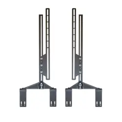
Part A (Pre-Assembled)
(2) VESA rails, (2) Bracket rails,
(2) Short swivel joints (part B),
(2) Long swivel joints (part C)
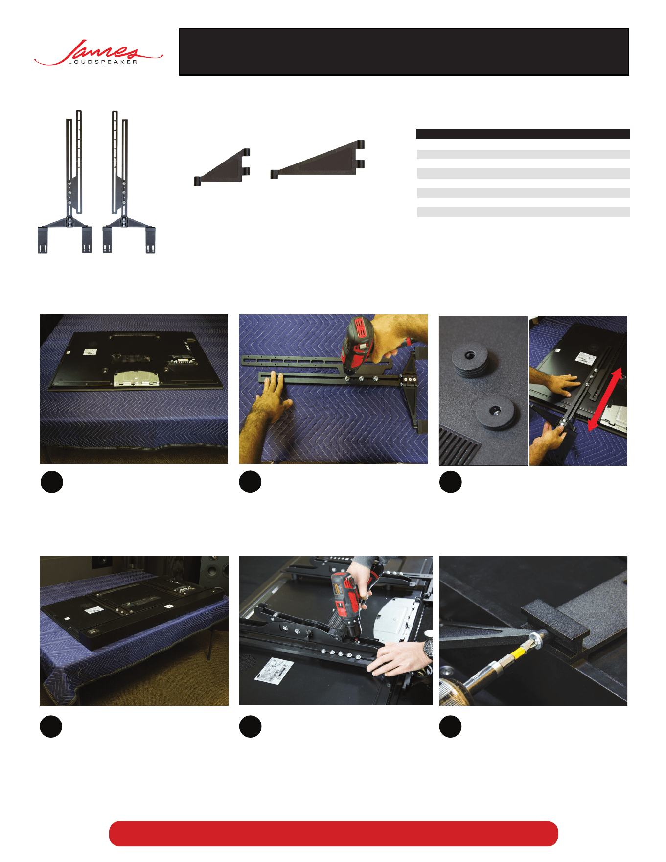
Place the display on a padded flat surface.
Loosen screws on bracket (Part A) and
pre-assembled swivel joints, so that they
can slide/pivot with little resistance.
If extra support is desired on the sliding
portion of the bracket, then use the
additional screws and washers provided.
1
2
3
Determine the amount of VESA spacers
needed (Bag #1). With or without the
spacer on the VESA pattern, the bracket
and slider should slide up and down
without interference from the SoundBar
or any protrusions on the rear of the
display.
9
Connect wires to terminals, ensuring
correct polarity, before mounting to wall.
7
10
James Loudspeaker | 535 Airpark Road, Napa, CA94558 | 707.265.6343 | www.JamesLoudspeaker.com
®
20180226
11
SPL5 UNIVERSAL MOUNTING BRACKET
8
A
Our wall mounts allow the hanging
of your display directly with our bracket.
(Purchased separately. P/N BRK.TV.UN)
B
Follow the manufacturer’s instruction
for the wall mount installation.
(Will require 2 or more people).
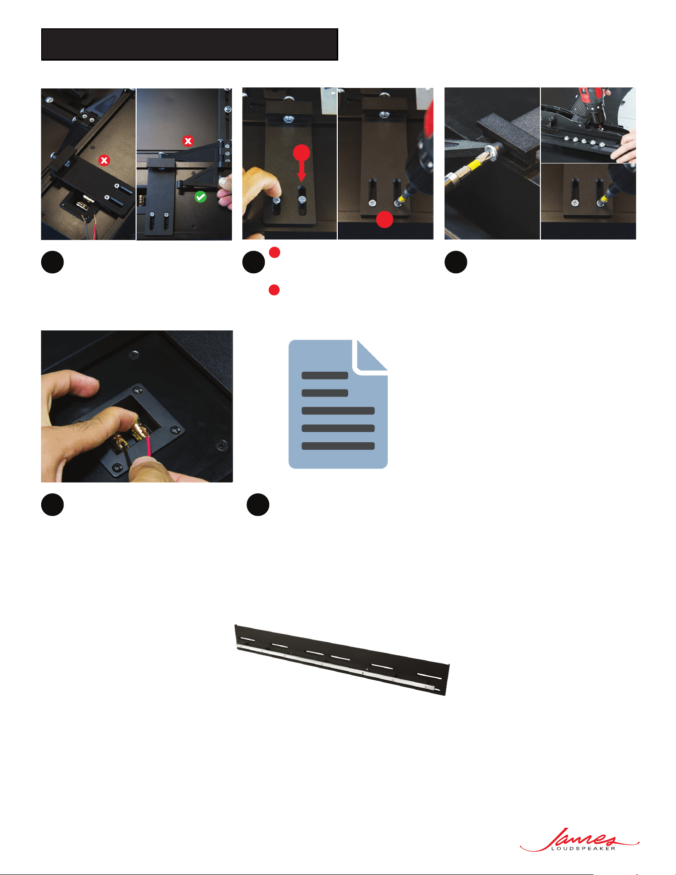
If the SoundBar terminals are blocked by
the SPL5 bracket holding tabs, then swap
the swivel joint with the alternate length,
either Part B or Part C.
Make all final adjustments to swivel
joints and bracket tabs, make sure to
avoid stressed positions/alignments.
Lastly, tighten all screws on joints & tabs
while applying constant pressure on the
SoundBar so that it’s snug against the
display while tightening fasteners.
- Slide the adjustable portion of the
holding tab into the bottom slot of
the SoundBar.
- Tighten the two screws on each of
the holding plates
A
B
