Manual
Version 2 software

Maxedia Manual
Version 2 2
© 2005 Martin Professional A/S, Denmark
All rights reserved. No part of this manual may be reproduced, in any form or by any means, without
permission in writing from Martin Professional A/S, Denmark.
Information subject to change without notice. Martin Professional A/S and all affiliated companies disclaim
liability for any injury, damage, direct or indirect loss, consequential or economic loss or any other loss
occasioned by the use of, inability to use or reliance on the information contained in this manual.

Maxedia Manual
Version 2 3
Table of contents
1. Packing and unpacking the Maxedia 4
1.1. Unpacking the Maxedia 4
1.2. Packing the Maxedia 4
2. Introduction 5
2.1. Maxedia safety information 5
2.2. Included items 5
2.3. AC Power 6
2.3.1. Power supply 6
2.3.2. Power connection 6
3. Connecting and starting up the Maxedia 7
3.1. What do I do if the monitor settings have been reset? 8
3.2. Connecting DMX devices 11
3.3. Maxedia IO-Box connections 12
3.3.1. Diagram 12
3.3.2. Actual representation 13
3.3.3. The different parts of the IO-Box 14
3.3.4. The menu of the IO-Box 15
3.4. Internal action of the Maxedia 16
3.5. Opening the Maxedia software 17
3.6. Structure of the Graphical User Interface 18
4. Tutorials 19
4.1. Representing cues 19
4.2. Clearing cues 20
4.3. Making cues 20
4.4. Recording cues 21
4.5. Adapting cues 22
4.5.1. Changing cue media 23
4.5.2. Adjusting parameters 24
4.5.2.1. Global 24
4.5.2.2. 3-D 25
4.5.2.3. Color 25
4.5.2.4. Effects 26
4.5.2.5. Video 27
4.6. Mixing cues 28
2.6.1. Mixing cues in four steps 29
4.7. Adjusting the Output Monitor 30
4.8. Importing media 31
2.8.1. Importing media in four steps 33
4.9. The DMX Viewer 36
4.10. Determining the layout 38
Appendix A: Plug-ins 43
Appendix B: The Configuration screen 48
Appendix C: DMX Layout 53

Maxedia Manual
Version 2 4
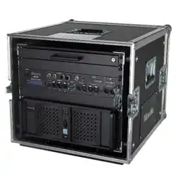
1. Packing and unpacking the Maxedia
1.1 Unpacking the Maxedia
To unpack the Maxedia:
1. Remove the top cover from the flight case.
2. Remove the front and rear flight case covers. The Maxedia can be operated
without removing it from its flight case.
1.2 Packing the Maxedia
To pack the Maxedia:
1. Disconnect the console from power.
2. Disconnect any external video monitors.
3. Replace the front and rear flight case covers and then the top cover. Do not
use excessive force.
4. The Maxedia can be wheeled, but for transport the flight case should be
placed resting on its wooden rails.

Maxedia Manual
Version 2 5
2. Introduction
Dear Maxedia user,
Thank you for purchasing the Maxedia software.
The Maxedia software is carefully designed to match the operating system. Do
not install any other software. Doing so could seriously affect performance and
make it impossible for the Maxedia to operate.
Do not modify the system in any way, as this may make it impossible to
provide service on the Maxedia!
The Maxedia user forum is available at http://www.martin.com/forum
2.1. Maxedia safety information
This product presents risks of lethal or severe injury due to electric shock. Read this
manual before powering or installing the console, follow the safety precautions listed
below and observe all warnings in this manual and printed on the console.
• Always ground (earth) the console electrically.
• Use only a source of AC power that complies with local building and electrical
codes and has both overload and ground-fault protection.
• Do not expose the console to rain or moisture.
• Refer any service operation not described in this manual to a qualified technician.
• Do not modify the Maxedia or install other than genuine Martin parts.
• Do not lift or carry the Maxedia alone.
2.2. Included items
The Maxedia is shipped in a flight case that contains the following items:
- Power cable
- Maxedia 19” computer
- IO-Box
- 19” keyboard with touchpad
- OS DVD
- Maxedia Media Content DVDs
Maxedia Manual
Version 2 6
2.3. AC Power
For protection from electric shock, the Maxedia must be grounded
(earthed). The AC mains supply must be fitted with a current overload
circuit breaker or fuse and ground-fault (earth-fault) protection device.
The Maxedia accepts 100 – 240 VAC nominal, 50/60 Hz. Do not operate the
Maxedia on supply voltages outside this range. The primary fuse is rated 6.3 A, 250
V slow-blow, high break capacity. Disconnect the device from power before changing
the fuse. Replace the fuse only with a T 6.3 AH 250 V fuse.
No user-serviceable parts inside.
To apply power, set the power switch to the I position.
2.3.1. Power supply
The Maxedia comes with an auto-sensing, auto-ranging switch-mode power supply.
Manual adjustments to the mains voltage and frequency are not necessary as the
Maxedia automatically adapts.
2.3.2. Power connection
For protection from electric shock, the Maxedia must be grounded
(earthed). The AC mains supply must be fitted with a fuse or current
overload circuit breaker and ground-fault (earth-fault) protection.
Connect the Maxedia directly to AC power. Do not connect it to a dimmer system.
Doing so may damage the system.
The Maxedia’s 3 AC power output connectors provide a total of 6.3 A maximum. The
voltage at these connectors is the same as the voltage applied to the AC power input
connector. Use the power output connectors only to connect low-power devices such
as the 19” Maxedia computer, external monitors and Ethernet switches.
2.3.3 Power cables
A power cable without a power connector is supplied. Only replace this cable with
one of the following types:
• SVT, 18 AWG x 3 – 16 AWG x 3
• SJT, 18 AWG x 3 – 14 AWG x 3
• H05VV-F, 3G 0.75 – 1.5
• 4V-75, 250/440 V, 3G 0.75 – 1.0
• 227 IEC53 (RVV), 300/500 V, 3G 0.75 – 1.5
Maxedia Manual
Version 2 7
A 3-prong power plug with live, neutral and ground (earth) pins rated 250 VAC, 10 A
minimum must be installed on the power cable following the plug manufacturer’s
instructions. Use a power plug of the approved type for your region. For example:
• USA: NEMA 5-15 A
• Europe: CEE or Schuko
• United Kingdom: UK BSI 13 A
• Denmark: SEV
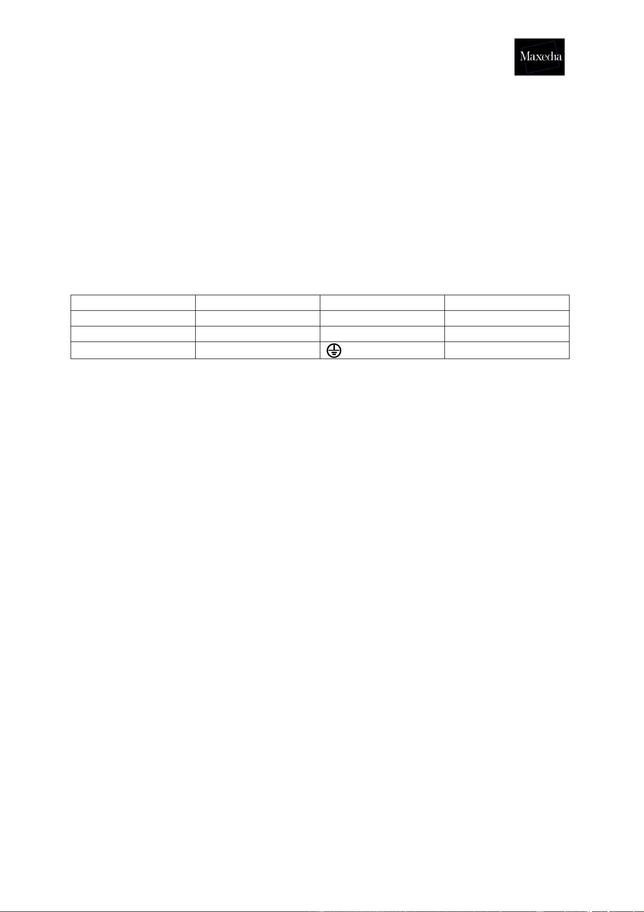
The table below shows some possible pin identification schemes. If pins are not
clearly identified, or if you have any doubts about proper installation, consult a
qualified electrician.
Wire color Pin Symbol Screw (USA)
Brown Live L Yellow or brass
Blue Neutral N Silver
Yellow/green Ground
Green
2.4 Media content DVD end-user license agreement
2.4.1 Permitted use
The media files provided on the Media Content DVDs may be used on Maxedia
Media Servers only. Owners of Maxedia systems may rent these files to another
person, company, organization or other entity only as part of a Maxedia system.
The media files on the Media Content DVDs may be incorporated into artistic works
such as live performances, films, videos, broadcasts, multimedia presentations,
advertisements, World Wide Web page, presentation or print project.
The media files on the Media Content DVDs may not be used in a defamatory,
scandalous, illegal, misleading, or otherwise unlawful manner and may not be used in
or in conjunction with pornographic material.
For further information, please view the readme.htm file on each Media content DVD.
2.4.2 Copyright
The files included on the Media Content DVDs are trademark, property and copyright
of their owners.
The media files on the Media Content DVDs may not be used, sold, licensed,
reproduced, distributed as stock or effects imagery elements, made available as
downloadable files or included in any other clip media/stock product, library,
collection, or set of clips for distribution or resale.
We wish to thank the following media content providers for contributing their work for

Maxedia Manual
Version 2 8
use by Maxedia users:
• DigiGobos http://www.digigobos.com
• Dean Price http://www.maxedia.de
• A Luna Blue http://www.alunablue.com
• Main Concept http://www.mainconcept.com/texture_loops.shtml
• Mode Studios http://www.modestudios.com
• Blue Pony Digital http://www.blueponydigital.com
• Sean Bridwell productions http://www.seanbridwellproductions.com
• Idyll Hands Imagery http://www.idyllhandsimagery.com
Maxedia Manual
Version 2 9
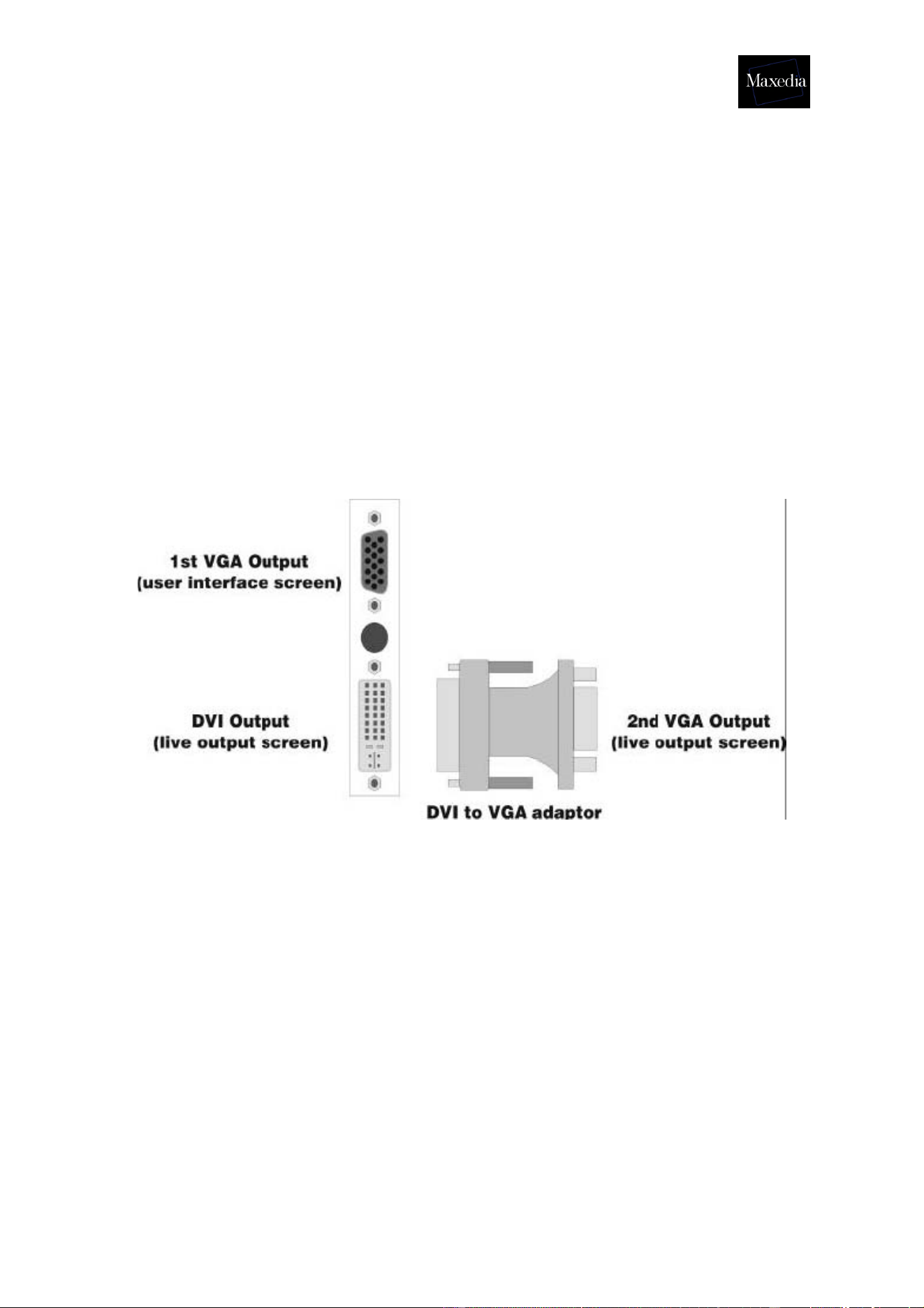
3. Connecting and starting up the Maxedia
! Always start up the Maxedia with both monitors connected.
The graphics card has two outputs. It is possible to connect a VGA monitor to the first
output and a DVI monitor to the second. If required, a VGA monitor can be connected
to the DVI output using a DVI-VGA adaptor.
The Maxedia starts up automatically and uses the DVI output for the second monitor
(live output screen). If only one monitor is connected, the system will reset all the
monitor settings.
Maxedia Manual
Version 2 10
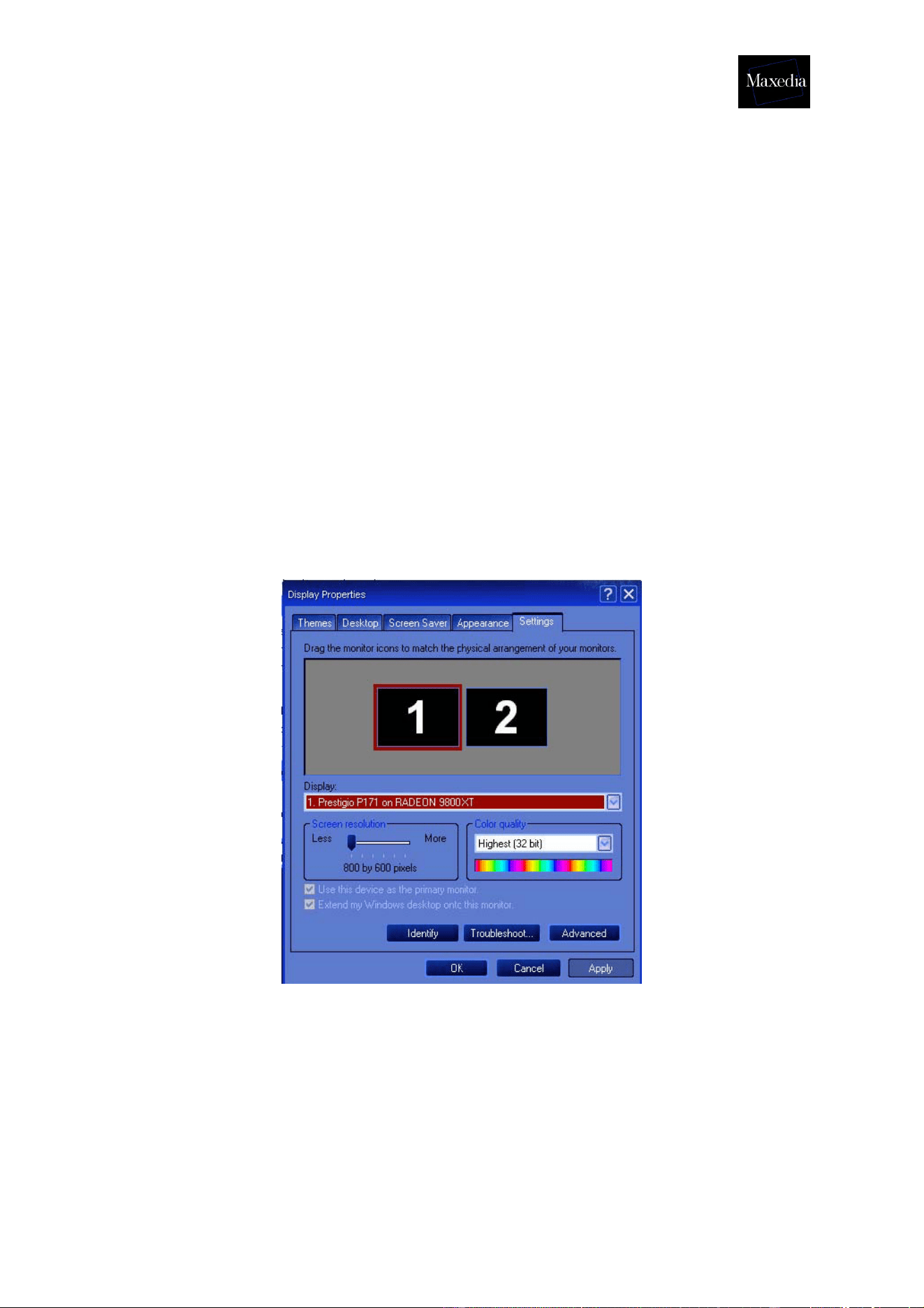
3.1. What do I do if the monitor settings have been reset?
If the monitor settings have been reset, follow the procedure described below to
restore them:
1. Start up the system and make sure that both monitors are connected.
2. Close the Maxedia software.
3. Right-click on the desktop and choose Display Properties.
4. Select Settings.
5. Click the Screen 2 button to activate it.
6. Mark the checkbox Extend my Windows desktop on to this monitor.
7. Click the Apply button.
8. Go to Advanced and choose Displays.
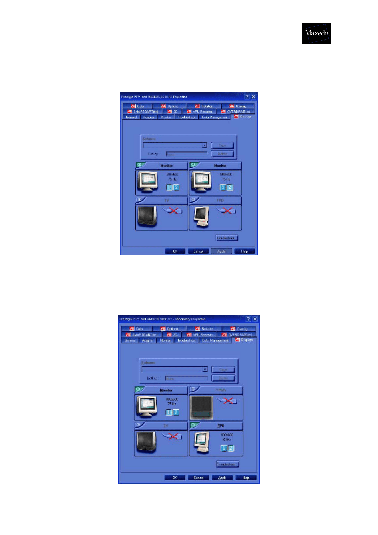
There are three possible options (see illustrations below):
• Two VGA-monitors
• One VGA-monitor and one DVI-monitor
• One VGA-monitor and one TV
9. Click the Apply button.
10. Go to the Windows Start Menu and start up Maxedia.
Maxedia Manual
Version 2 11
• When the two VGA monitors are connected (see illustration below):
a) The left monitor must be 1.
b) The right monitor must be 2.
• When one VGA monitor and one DVI monitor are connected (see illustration
below):
a) The VGA-monitor must be 1.
b) The FPD-monitor must be 2.
Maxedia Manual
Version 2 12
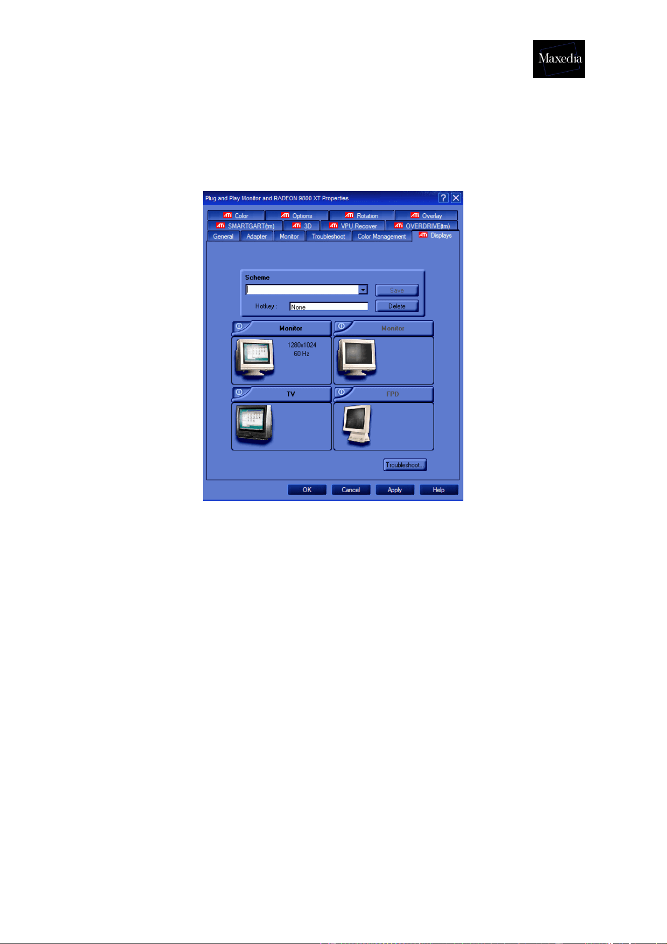
• When one VGA monitor and one Composite or S-Video monitor are connected
(see illustration below):
a) The VGA-screen must be 1.
b) The TV must be 2.

Maxedia Manual
Version 2 13
3.2. Connecting DMX devices
• The Maxedia has 5-pin XLR sockets for DMX input and output. The pin-
put on all sockets is pin 1 to shield, pin 2 data cold/compliment (-), and
pin 3 to data hot/true (+).
• Use shielded twisted-pair cable designed specially for DMX devices:
standard microphone cable cannot transmit control data reliably. 24
AWG cable is suitable for runs up to 300 meters (1000 ft.) Heavier
gauge cable and/or an amplifier are recommended for longer runs.
• To split the DMX link into multiple branches, use a splitter such as the
Martin 4-Channel Opto-Isolated RS-485 Splitter/Amplifier. Never use a
Y-cable.
• Do not overload the link. Up to 31 additional devices may be connected
on any given DMX link.
• Terminate the link by installing a termination plug in the output socket of
the last fixture. The termination plug, which is a male XLR plug with a
120 ohm, 0,25 watt resistor soldered between pins 2 and 3, “soaks up”
the control signal so it does not reflect and cause interference. If a
splitter is used, terminate each branch of the link. Please note that
some fixtures and dimmers provide onboard termination and do not
require an external terminator. Consult the user manual of the DMX
device for details.
• Martin fixtures introduced before 1997 have reversed polarity data
sockets (pin 2 + and pin 3 -). The socket polarity is labelled. Use a
phase-reversing cable between the Maxedia and any device with
reversed polarity.
Maxedia Manual
Version 2 14
3.3. Maxedia IO-Box connections
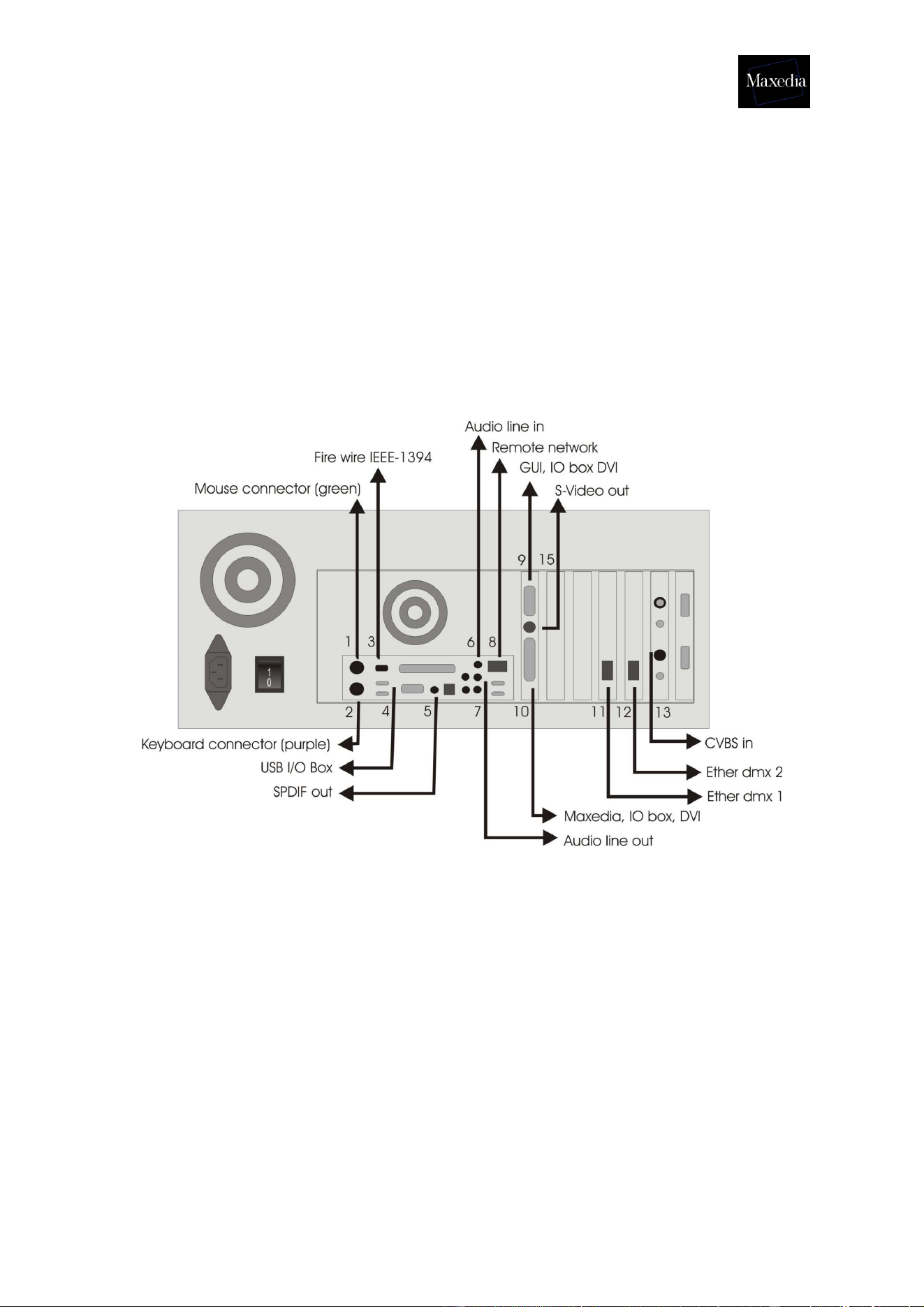
3.3.1. Diagram
This document describes how to connect the Maxedia with the IO-Box. All the cables
needed are enclosed in the flight case.
Maxedia PC connections
1. Mouse connector (Green), keyboard drawer, mini DIN6.
2. Keyboard connector (Purple), keyboard drawer, mini DIN6.
3. Fire wire IEEE1394, peripheral cable, IEEE1394 6pin female.
4. USB, peripheral cable, USBA.
5. SPDIF Out, peripheral cable, male RCA.
6. Audio line in, peripheral cable, male stereo jack.
7. Audio line out, peripheral cable, male stereo jack.
8. Remote Network, peripheral cable, RJ45.
9. GUI, IO box, DVI.
10. MAXEDIA, IO box, DVI.
11. Ether DMX1, peripheral cable, RJ45.
12. Ether DMX2, peripheral cable, RJ45.
13. CVBS In, peripheral cable, BNC.
14. S-Video out, mini DIN4.
15. SDI In, peripheral cable, BNC (not used).
Maxedia Manual
Version 2 15
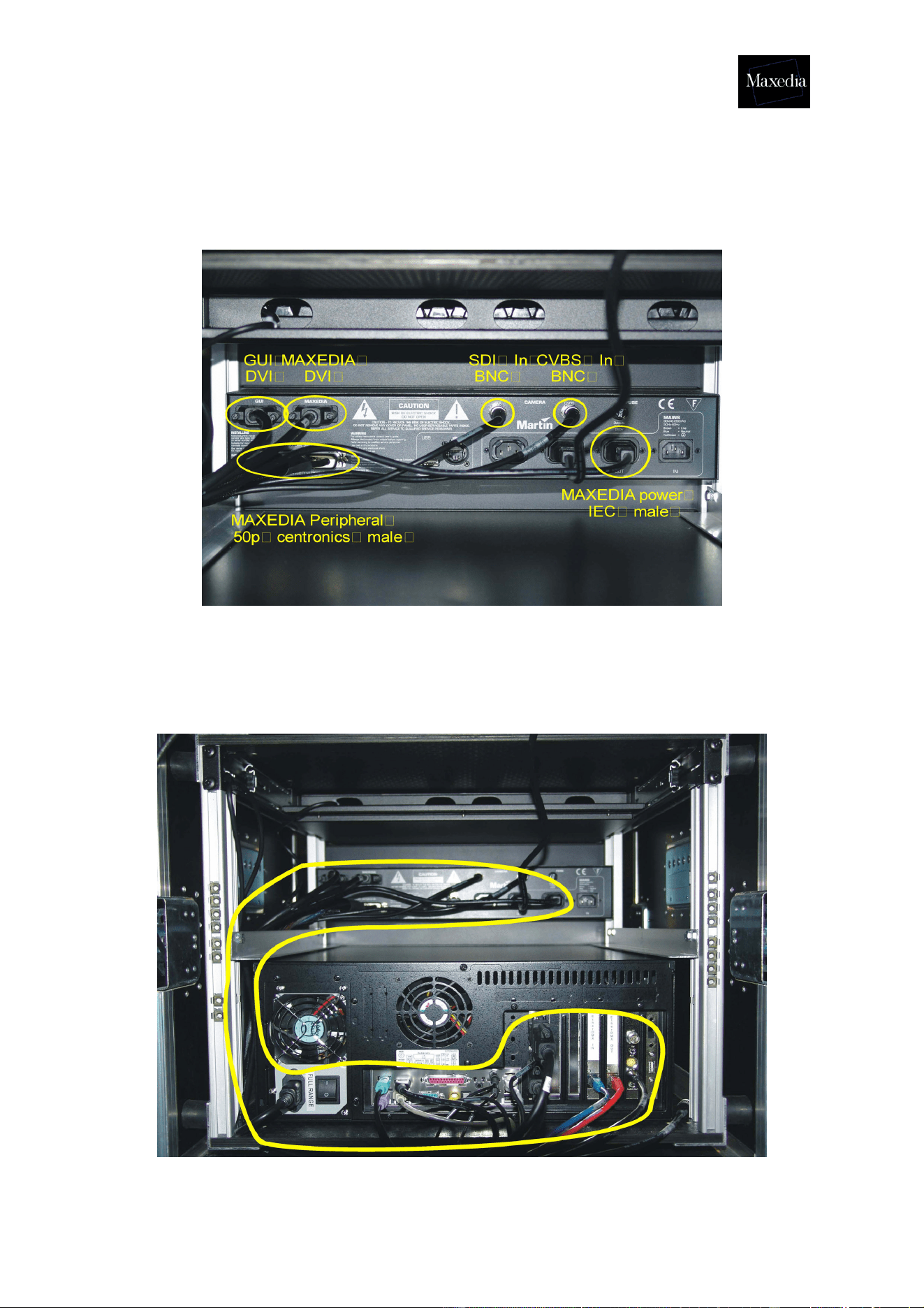
3.3.2. Actual representation
IO-Box connections
Overall cable arrangement
Standard routing for all cables is on the side of the flight case (see illustration below).
Maxedia Manual
Version 2 16
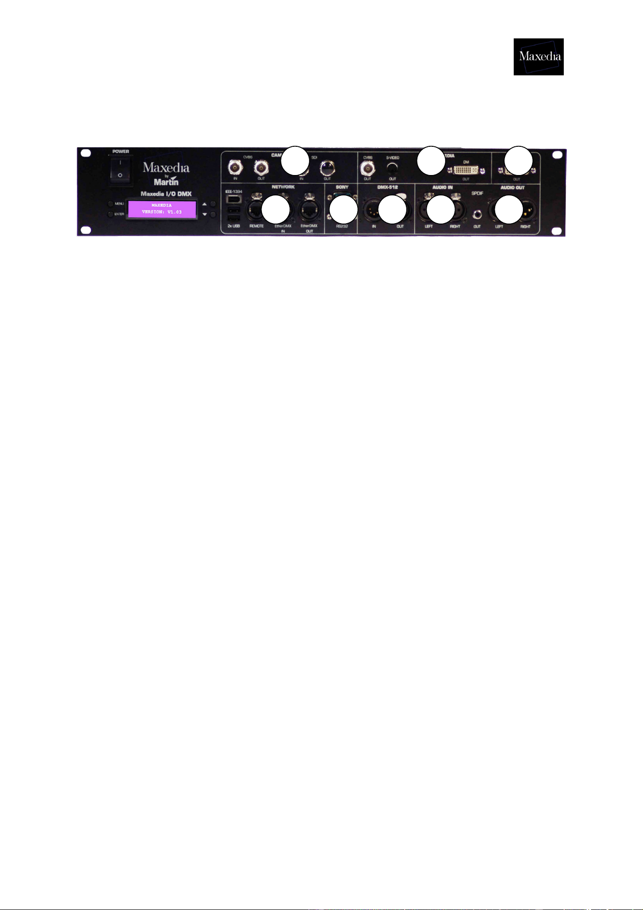
3.3.3. The different parts of the IO-Box
1. Camera Inputs:
CVBS IN = Composite video input.
CVBS OUT = Buffered CVBS IN signal.
SDI IN = SDI video input.
SDI out = Buffered SDI IN signal.
2. Maxedia
CVBS out = Composite video output from the Maxedia Engine.*
S-VIDEO out = S-Video output from the Maxedia Engine. *
DVI-out = The DVI output from the Maxedia Engine.
* see section 1.1.1.
3. GUI
DVI-out = The graphical user-interface output from the Maxedia (graphics card
VGA signal).
4. Network
IEEE-1394 = Firewire connection.
2x USB = 2 USB connections.
Remote = 1 Gbit Ethernet Connection to the maxedia.
EtherDMX IN = ArtNet DMX input Connection.
EtherDMX OUT = Artnet DMX output Connection.
5. Sony
RS422 = Serial interface connection.
RS232 = Serial interface connection.
6. DMX-512
IN = 5-pin DMX input.
OUT = 5-pin DMX output.
7. AUDIO IN
LEFT = left audio input signal. (XLR)
RIGHT = right audio input signal. (XLR)
1 2 3
4 5 6 7 8

Maxedia Manual
Version 2 17
8. AUDIO OUT
SPDIF = Sony/Philips Digital Interface.
LEFT = left audio output signal. (XLR)
RIGHT = right audio output signal. (XLR)
3.3.4. The menu of the IO-Box
- The Menu button can be used for opening new menus and for returning to a
previous menu.
- The two arrow buttons can be used for moving through a menu.
- The Enter button can be used for opening menus and executing commands.
The IO-Box-menu:
1. Test Images
1.1. Normal
1.2. Color Bar
1.3. Luminance Bar
1.4. Alignment
1.5. Video 1 in
1.6. Video 2 in
2. DMX-In
2.1. Set DMX-Base Address
2.2. Set DMX Output Adjustment Address
2.3. Set DMX Layer Address
2.4. Set Number of Layers
2.5. Select DMX Protocol (DMX In/Artnet)
2.6. DMX Base Universe
2.7. DMX Output Adjustment Universe
2.8. DMX Layer Universe
2.9. DMX Base Active (On/Off)
2.10. DMX Output Adjustment Active (On/Off)
2.11. DMX Layer Active (On/Off)
3. Global Settings
3.1. Set Boxname
3.2. Set Autoscroll (On/Off)
4. Defaults
4.1. Save Userdefault
4.2. Load Userdefault
4.3. Load MFGDefaults
5. Diagnostics
5.1. DMX Viewer
5.2. Connection Test
Maxedia Manual
Version 2 18
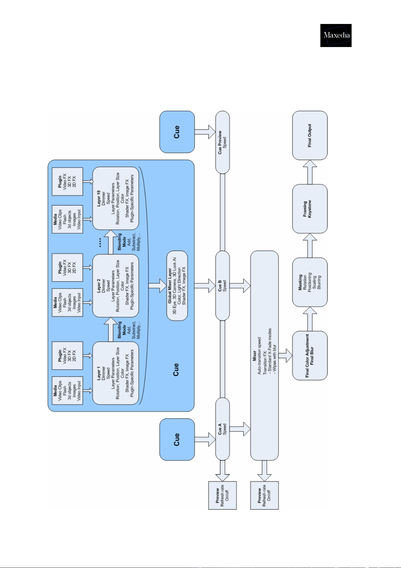
3.4. The internal action of Maxedia (diagram)
Maxedia Manual
Version 2 19
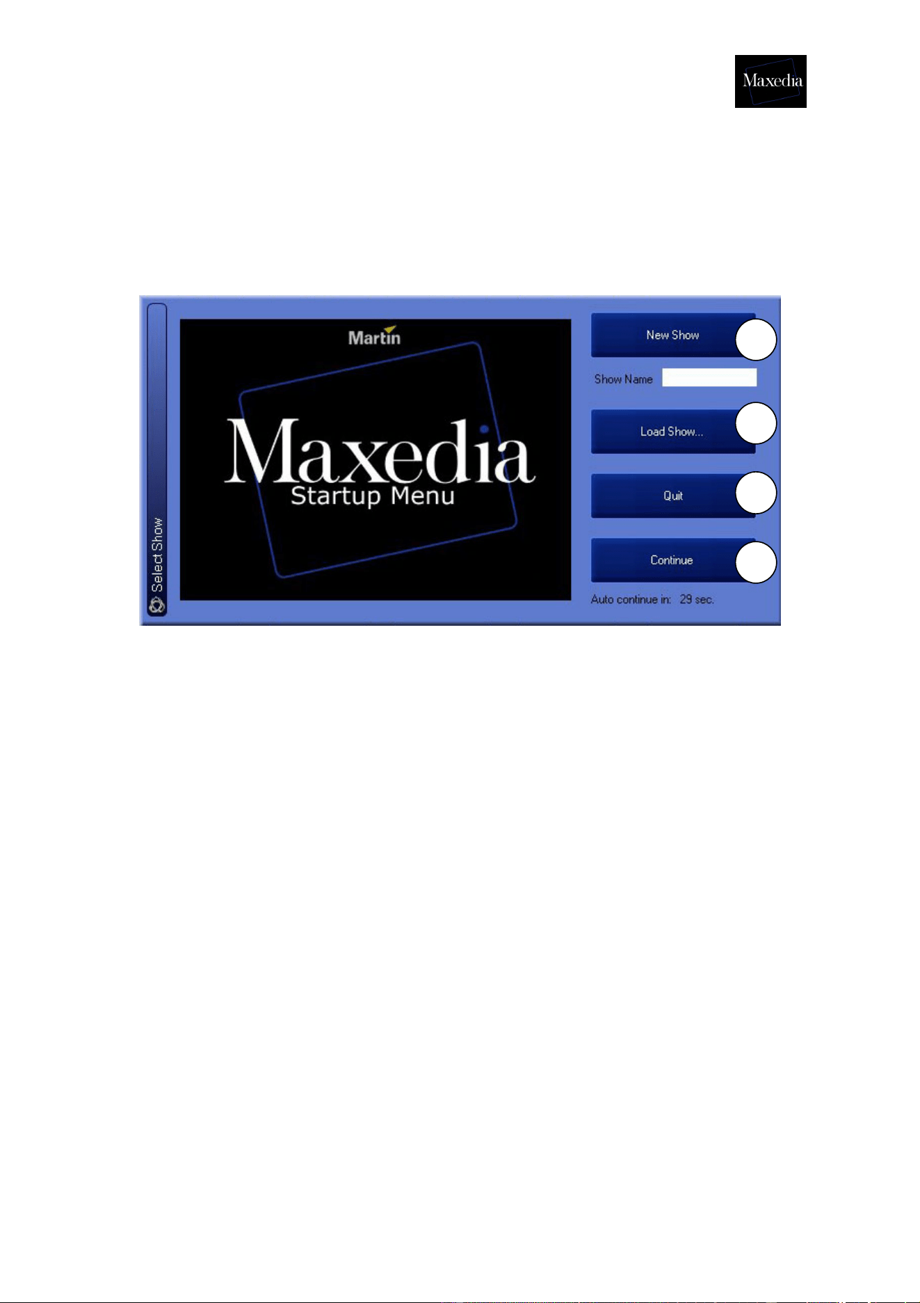
3.5. Opening the Maxedia software
If all connections have been made correctly, the Maxedia can be powered on. After
start-up, a welcome-screen appears.
There are four possible options (see illustration above):
1. New Show: This option starts up a completely new blank show without any
loaded cues. Do not forget to give the new show a name.
2. Load Show...: This option loads a stored show.
3. Quit: This option closes the Maxedia software down.
4. Continue: This option reloads the last show.
! Click Load Show to continue and open the Martinmaxediashow.mxshow
file. The location of this file is
c:\programfiles\martin\maxedia2\martinmaxediashow.mxshow
1
2
3
4
Maxedia Manual
Version 2 20
3.6. Structure of the Graphical User Interface
The Maxedia’s Graphical User Interface (GUI) consists of three main parts (see
illustration above):
1. Screen Selector: This bar represents the different pages which can be
displayed.
2. Action field: Here most of the action takes place: all cues are made, media
are imported and manipulated and the shows are created.
3. Command Bar: This bar represents all standard commands:
1. Record: Storing items
2. Copy: Make a copy of items
3. Move: Change location of items
4. Delete: Remove items
5. Edit: Add items
6. Clear: Undo a command
7. Enter: Execute a command
8. Config: Display the configuration screen
9. Medialibrary: Display the media library
10. Quit: Close down Maxedia
1
2
3
Maxedia Manual
Version 2 21
4. Tutorials
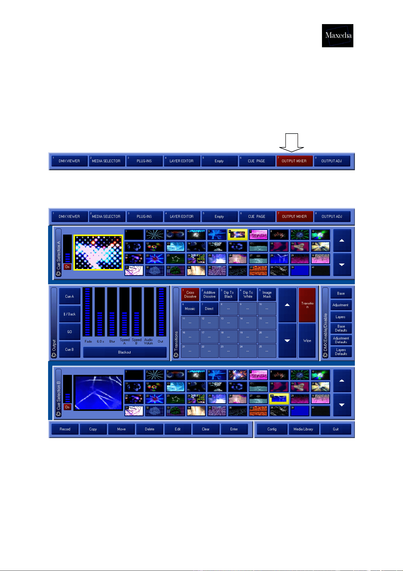
4.1. Representing cues
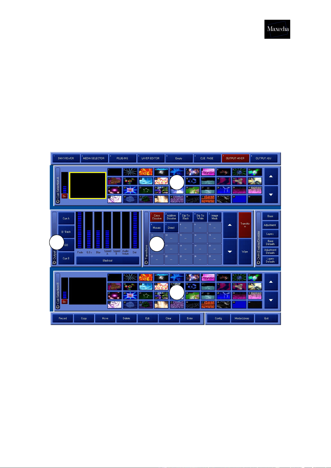
Click the Output Mixer button in the Screen Selector-bar.
This is the Output Mixer screen:
Before a cue can be played back, it must be selected from the cue selection list.
Only selected cues (cues in a yellow frame) will be visible on the Output screen.
Maxedia Manual
Version 2 22
4.2. Clearing cues
The selected cues can easily be deleted by clicking the Clear Programmer button in
the Layer Editor (see drawing below).
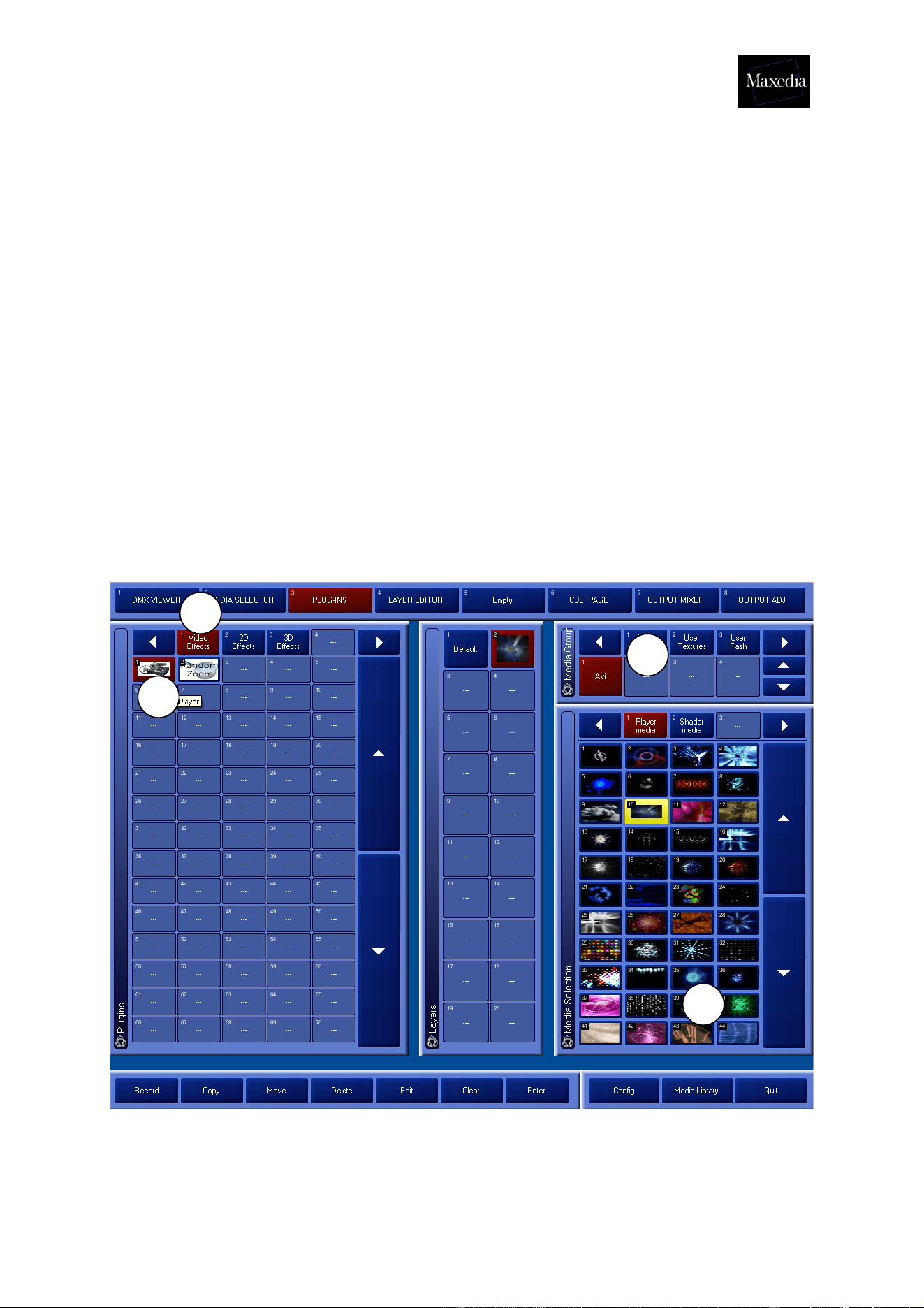
4.3. Making cues
Cues can be made with plug-ins by following this procedure (see illustration below):
1. Click the Video Effects button.
2. Double click the Video Plug-in icon. The plug-in will be loaded.
3. Click on a video file.
a) Media Groups: group and directory can be selected.
b) Media Selection: items can be selected.
The first cue is produced and will appear on the Output screen.
!
1
2
3
Maxedia Manual
Version 2 23
! It is possible to load 20 plug-ins in a cue. Repeat steps 2 to 4 to load plugins.
! Making cues is also possible by using the Plug-in button in the Screen Selector.
Follow the four steps above in this case also.
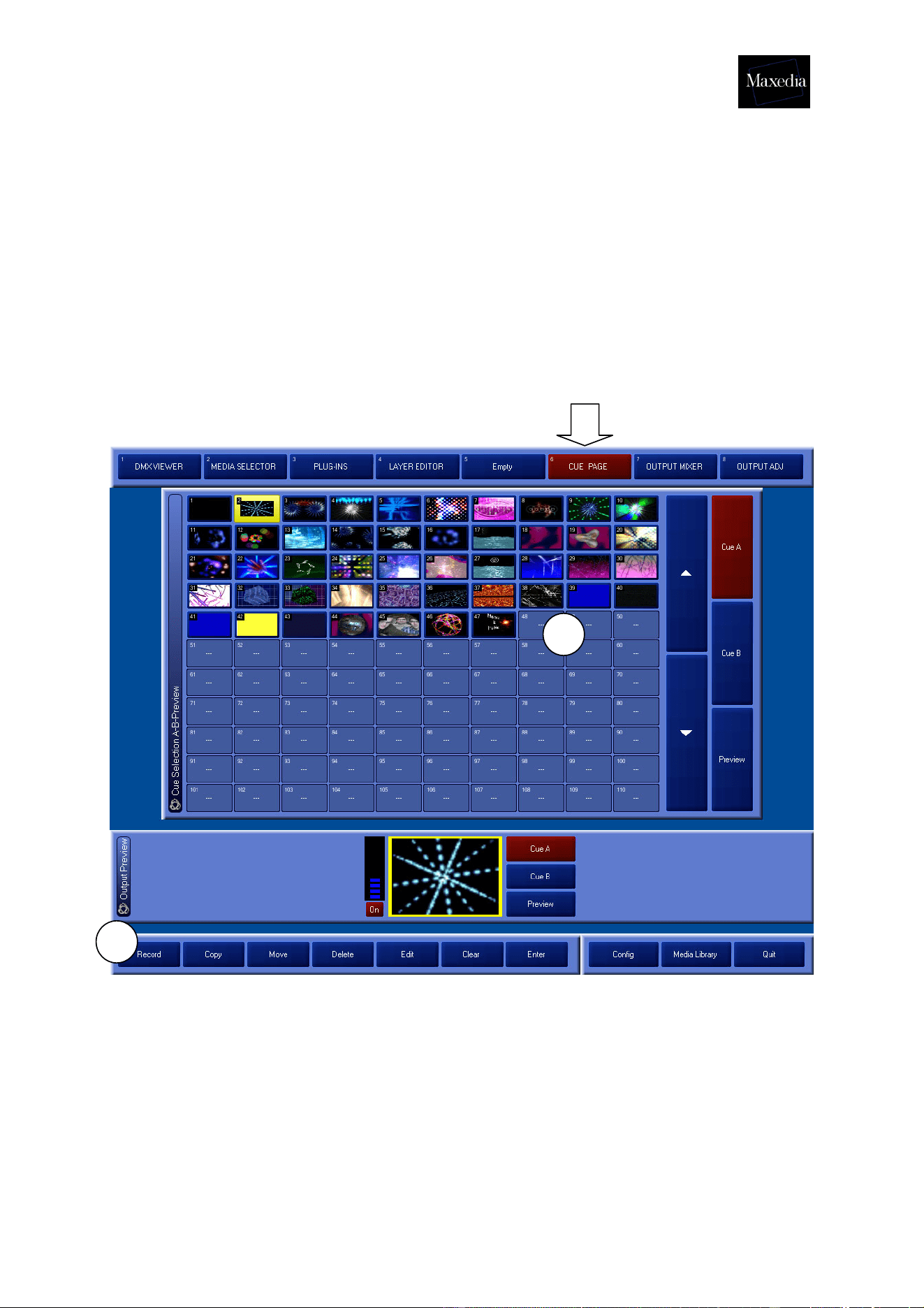
4.4. Recording cues
Choose Cue Page in the Screen Selector.
Follow the procedure mentioned below (see illustration above):
1. Click the Record button.
2. Click in an empty box.
The cue is now recorded.
1
2
Maxedia Manual
Version 2 24
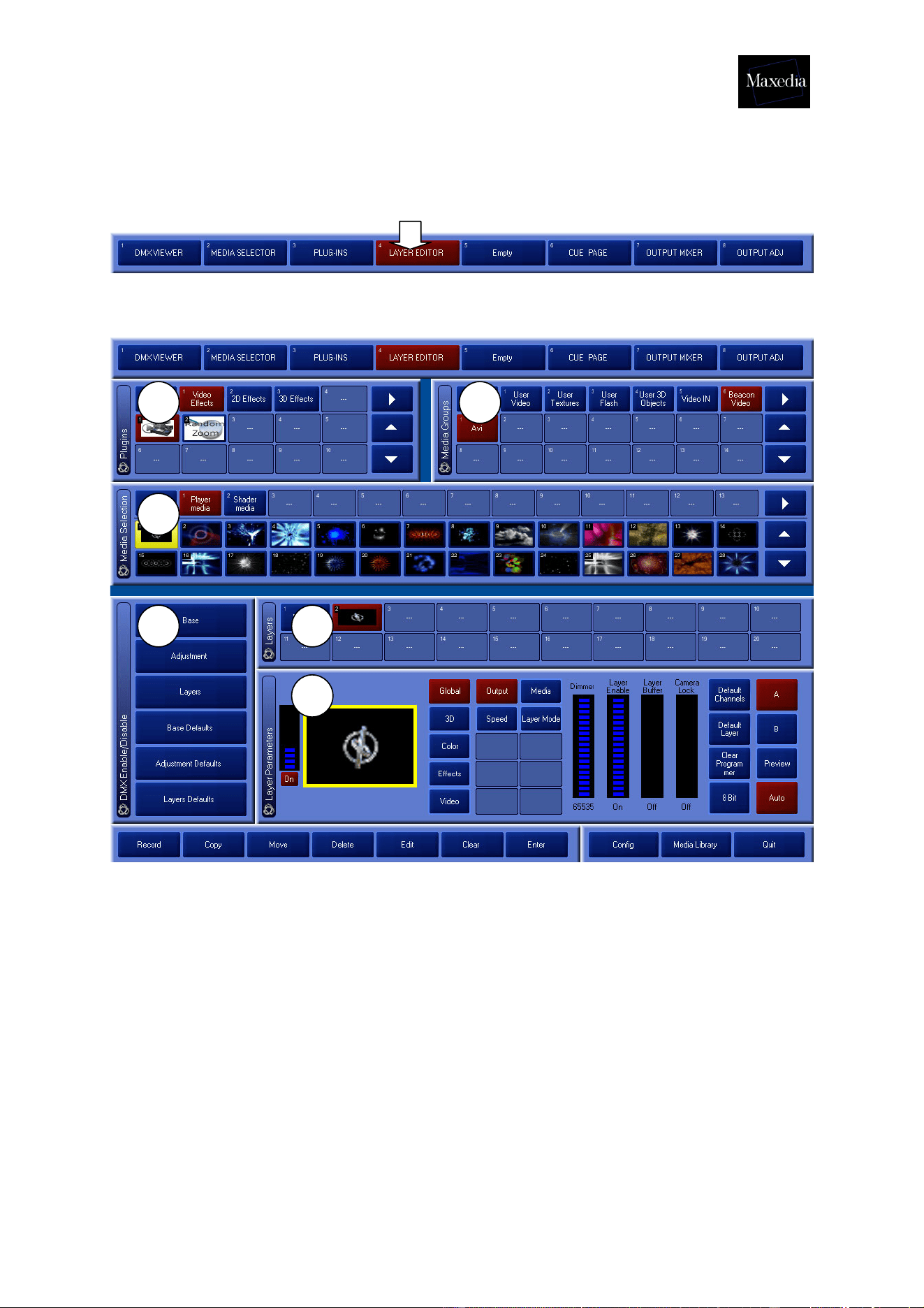
4.5. Adapting cues
Choose Layer Editor in the Screen Selector.
This is the Layer Editor screen:
This screen offers the possibility of fine tuning and improving cues.
The Layer Editor-screen contains 6 different panels (see illustration above):
1. Plug-in: plug-ins are selected.
2. Media Group: media type and the group are selected.
3. Media Selection: media are selected.
4. Layers: The internal representation of a cue (one cue consists of 20
layers)
5. DMX Enable/Disable: Adjust the DMX access to control this board from
the lighting panel.
6. Layer Parameters: The fine tuning of each layer and the possibility of
adjusting parameters such as 3D movement, 3D rotation, blending, color
and effects.
1 2
3
4 5
6
Maxedia Manual
Version 2 25
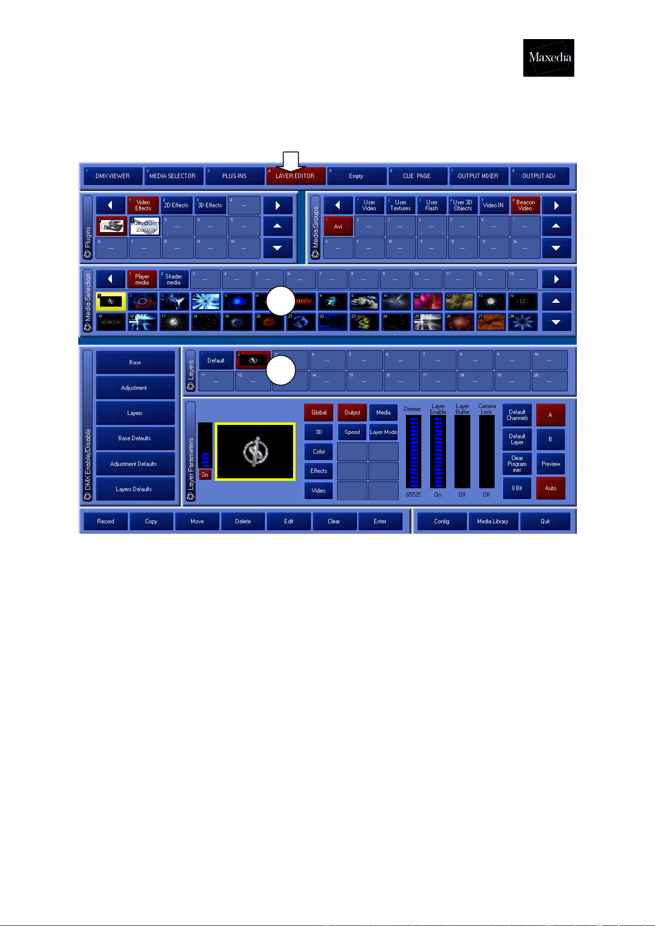
4.5.1. Changing cue media
Choose Layer Editor in the Screen Selector.
! Use the Media Library to add or delete media (at the bottom right in the Command
bar. See section 2.8.).
Change cue media in two steps (see illustration above):
1. Select the layer or create the layer (see section 2.3.)
2. Select the media. The following media are now available:
- Media Groups: group and directory can be selected.
- Media Selection: items can be selected.
1
2
Maxedia Manual
Version 2 26
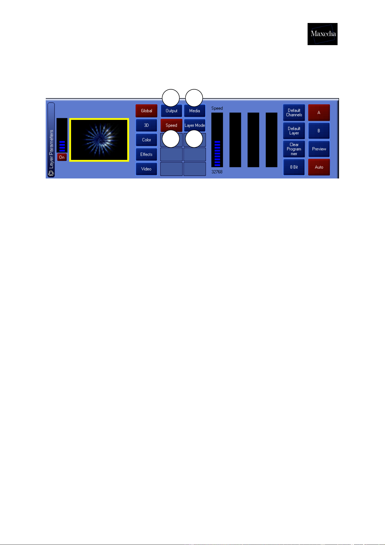
4.5.2. Adjusting parameters
4.5.2.1. Global
1. Output:
- Dimmer
- Layer on/off
- Layer Buffer on/off
- Camera Lock on/off
2. Speed: Here the speed can be adjusted.
3. Media:
- Group
- Subgroup
- Item
- Output: layers can be added, subtracted and multiplied (eg. Taking
the maximum of both layers, taking the minimum of both layers,
making black transparent, making black transparent).
Always select the last layer and then apply the operation.
4. Layer Mode: Advanced layer modes
! Click the Default Channels-button to put the original parameter values
back.
1
2
3
4
Maxedia Manual
Version 2 27
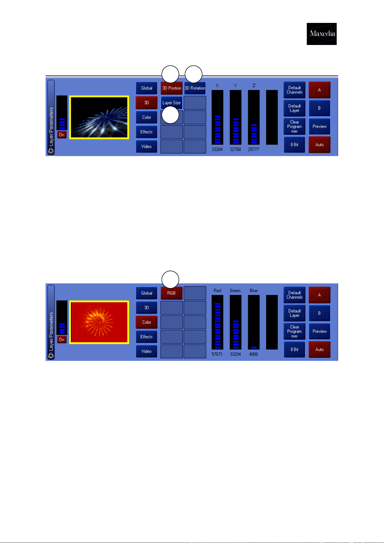
4.5.2.2. 3-D
1. 3D Position: Determine the position by using the X-, Y- and Z-bars.
2. 3D Rotation: Determine the rotation by using the X-, Y- and Z-bars.
3. 3D Layer Size: Determine the layer size by using the X-, Y-, Z-bars and
Aspect Ratio.
! Click the Default Channels-button to put the original parameter values
back.
4.5.2.3. Color
1. RGB: Determine the color by using the Red-, Green- and Blue-bars. It
is possible to add or subtract the color depending on the position of the
bar.
! Click the Default Channels-button to restore the original parameter values.
1 2
3
1
Maxedia Manual
Version 2 28
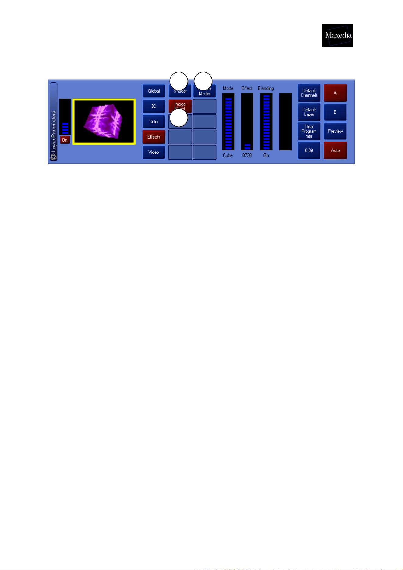
4.5.2.4. Effects
1. Shader Effects:
- Reverse: Inverts color values (first bar only).
- Greyscaling: Turns the screen into black and white (first bar only).
- Edge: Makes edges visible (first bar only).
- R-edge: Applies Reverse and Edge at the same time (first bar only).
- Postarization: Appllies postarization (first bar only)
- Separate Shift: Shifts colors (first bar only).
- Separate Rotation: Shifts and rotates colors (first bar only).
- Gaussian Blur: Blurs the video (first bar only).
- Zoom (Shine-effect): Allows zooming along the three axes (first three
bars only).
- Replace: Replaces colors (first bar only).
- Glare: Creates a glow (first two bars for amount of glow and fine
tuning).
- R-glare: Creates reverse glow (first two bars for amount of glow and
fine tuning).
2. Image effects:
- Tile: Adjusts screen division or tiling.
- Dot: Transforms image into small dots.
- Mosaic: Transforms the image into a mosaic.
- Mirror: Reverses the image (the X-axe, Y-axe and both at the same
time).
- Oil Paint: Applies an oil painting-texture.
- Ring: Transforms the image into a ring-shaped form.
- Cube: Transforms the image into a cube-shaped form.
- Cube Vision: Applies Cube and Tile effects at the same time.
3. Shader Media: Generates a mask to apply the Shader (black and white
equal both at 100%).
! Click the Default Channels button to restore original parameter values.
1
2
3
Maxedia Manual
Version 2 29
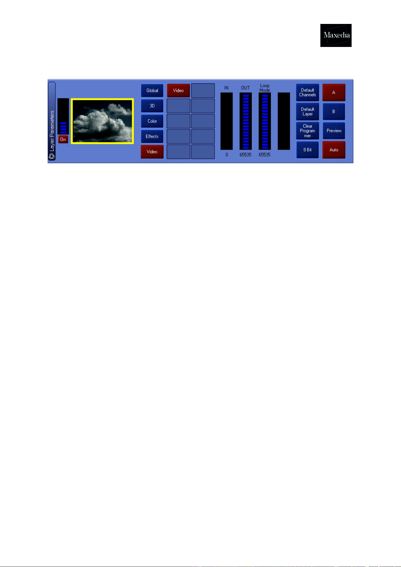
4.5.2.5. Video
This differs depending on the plug-in used (see Appendix A).
! Default Layer makes it possible to apply all the Defaults the same time. All
parameters and media will be returned to their original values.
! By using 8 Bit-16 Bit all parameters can be set with precision.
Maxedia Manual
Version 2 30
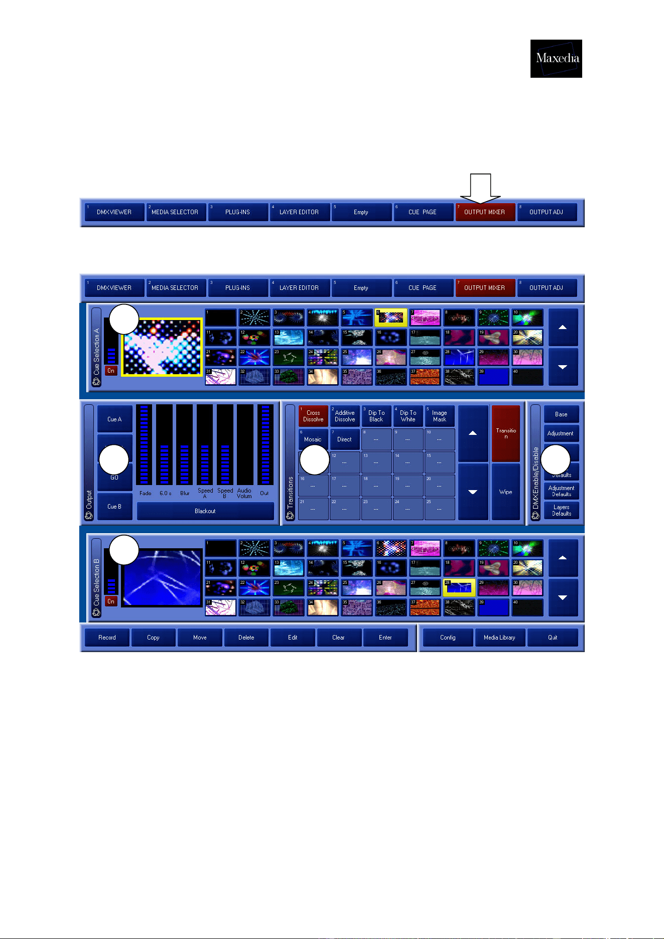
4.6. Mixing cues
The Maxedia software mixes cues from A to B and back.
Choose Output Mixer in the Screen Selector.
This is the Output Mixer screen:
The Output Mixer screen contains five different panels (see illustration above):
1. Cue Selection A: Load a cue by clicking on it.
2. Cue Selection B: Load a cue by clicking on it.
3. DMX Enable/Disable: Gives the DMX console access to the parameters
on this screen.
4. Transitions: Allows selection of different kinds of transition.
5. Output: Allows adjustment of transition parameters, output monitor display
or switching between one cue and another (manually or automatically).
1
2
345
Maxedia Manual
Version 2 31
4.6.1. Mixing cues in 4 steps
If the function of each panel in the Output Mixer screen is clear, then the mixing of
the cues can start:
1. Select a cue in A.
2. Select a cue in B.
3. Choose the desired transition
• Either via the Transition Page
• Either via the Wipe Page (Wipe regulates the transition on the basis of
greyscales. Wipe can be set precisely by using the Blur Parameter.)
4. Clicking the Go button starts the transition from A to B or from B to A.
1
2
3
4
Maxedia Manual
Version 2 32
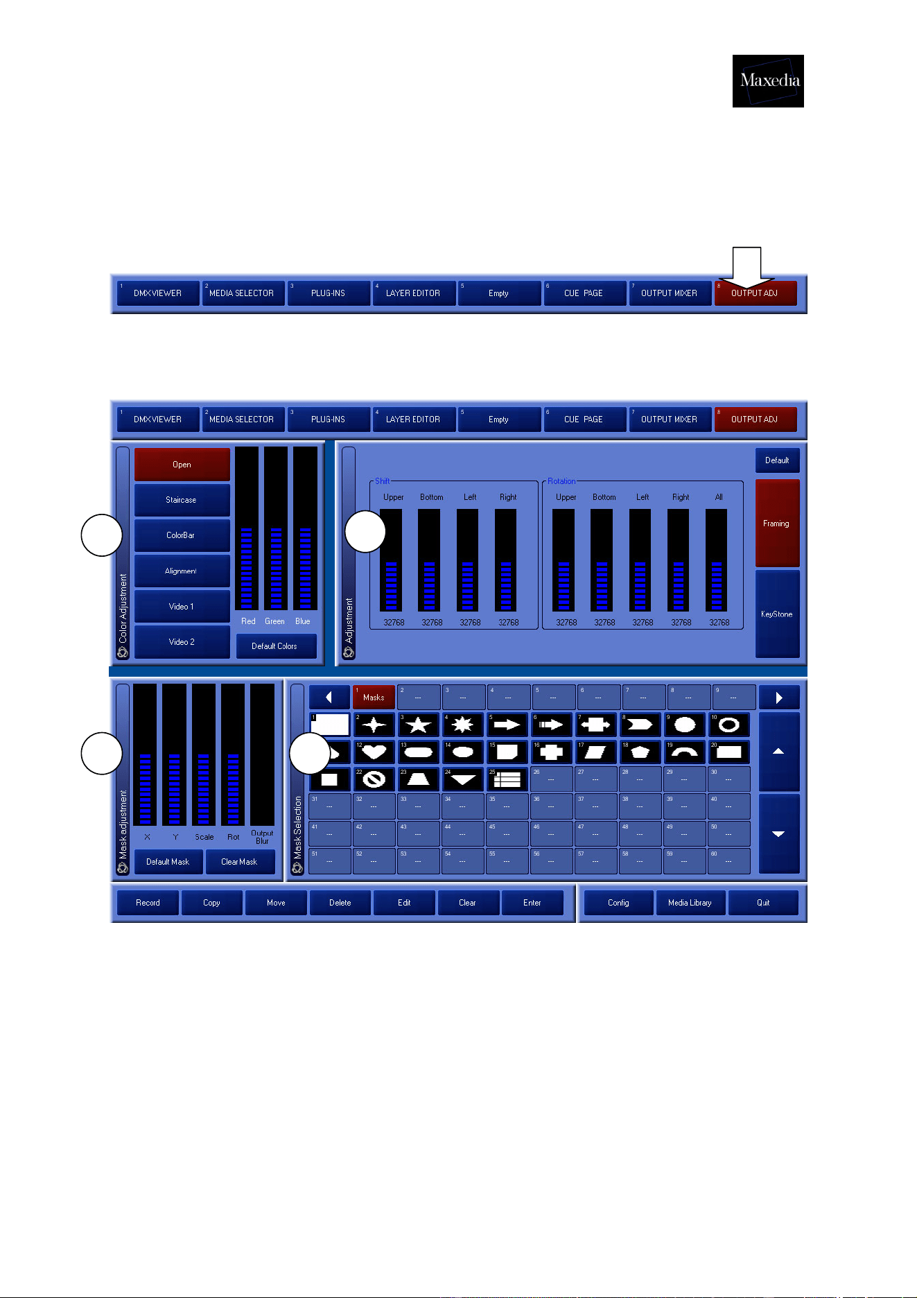
4.7. Adjusting the Output Monitor
Choose Output Adj in the Screen Selector.
This option makes it possible to change the colour (to add or to subtract colour), to
cut off angles and to keystone.
This is the Output Adj-screen:
1. Color Adjustment: Allows adjustment of output colors. Also allows different
types of test cards to be displayed to calibrate the screen or beamer.
2. Adjustment: Allows adjustment of size, rotation and keystoning of the output.
3. Mask Selection: Selects the type of mask that will be used.
4. Mask Adjustment: Adjusts the desired mask.
1
2
3 4
Maxedia Manual
Version 2 33
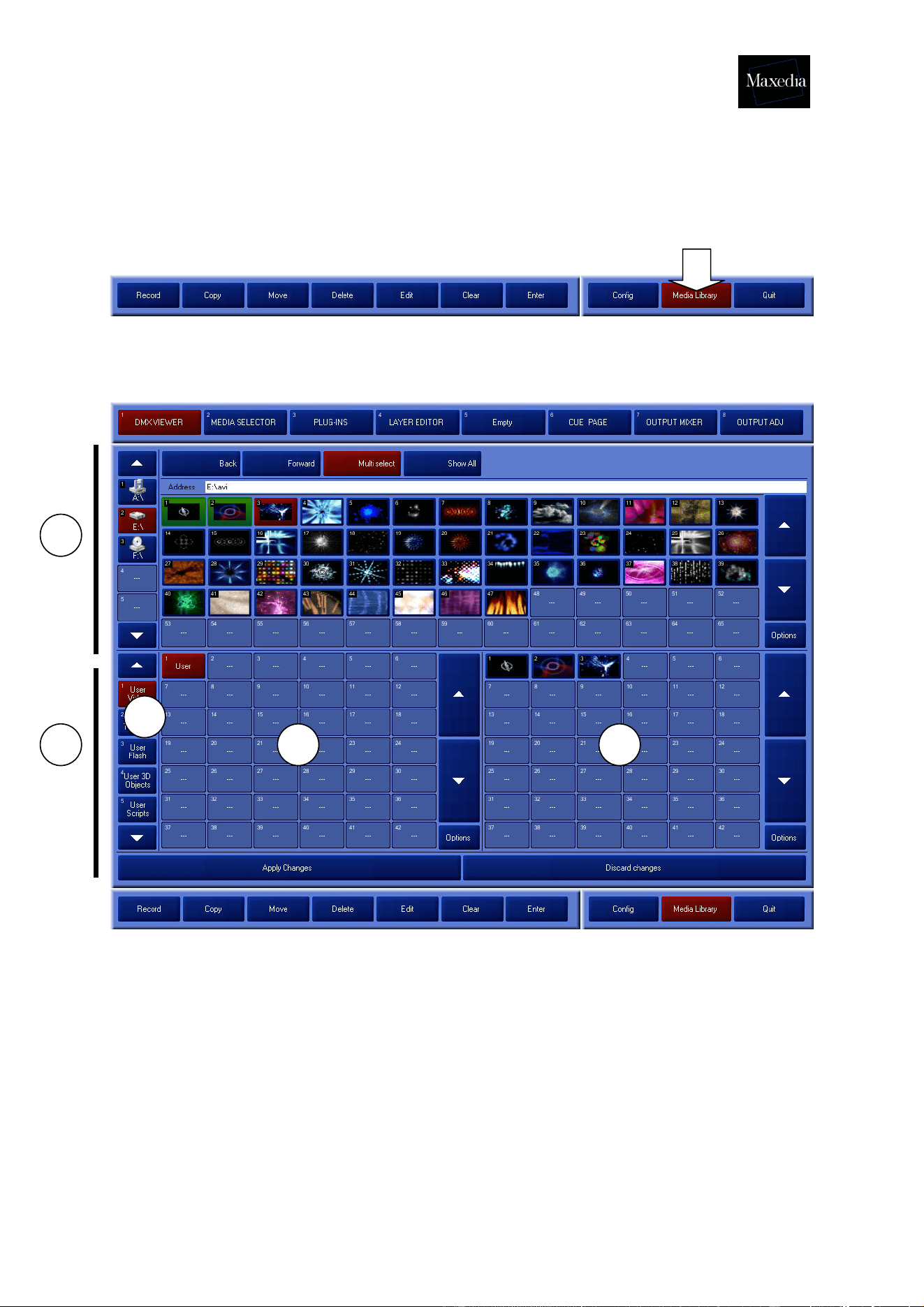
4.8. Importing media
The Media Library must be used to import own media.
Choose Media Library in the Command bar:
This is the Media Library screen:
5
1
2
3
4

Maxedia Manual
Version 2 34
The Media Library-screen contains 4 parts:
1. Viewer: Allows browsing through the Maxedia’s physical discs. USB memory
sticks can also be used. These sticks will be detected automatically.
2. This area allows the information stored on the discs to be loaded internally.
3. Groups: Allows selection of different types of media.
The media that are recognized by the Maxedia software will be divided into
seven groups. The first five groups are visible at the bottom left of the screen.
! These toolbars function as filters for the Viewer.
Example 1: To load Textures, the Texture group must be clicked first. Then
a Texture file can be selected.
Example 2: To load video clips from a disc, the Video group must be clicked
first. Then a Video file can be selected.
4. Subgroups: Here the subdivisions of the types of media can be browsed
through.
5. Items: Here the media files of each subgroup can be browsed through.
! The process of importing media is faster if no cues or programs are activated.
Maxedia Manual
Version 2 35
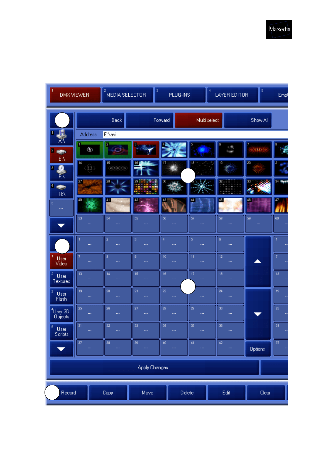
4.8.1. Importing media in four steps
Choose Media Library in the Command bar.
1
2
3
4
5
Maxedia Manual
Version 2 36
1. Select the drive which contains the desired media.
2. Select the media type.
3. Select the desired media.
4. Click the Record button in the Command bar.
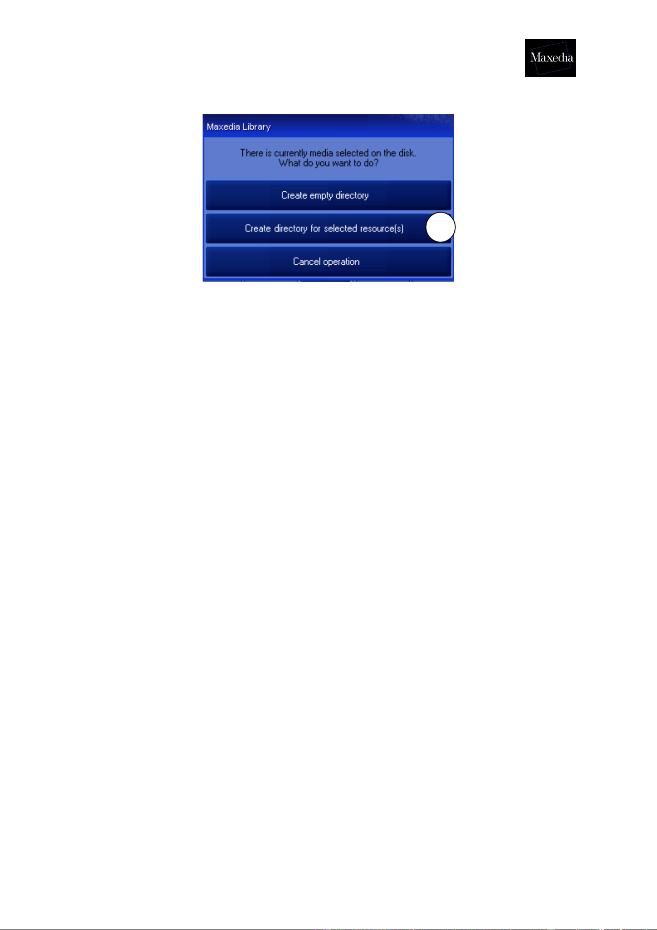
5. Click on an empty box in the left panel below the media (The panel with the
AVI-folder).
6. Click the Create directory for selected resource(s) button to confirm.
! It is possible to select more than one item at a time by double-clicking on the first
item and clicking once on the last item. All items in between will be selected.
6
Maxedia Manual
Version 2 37
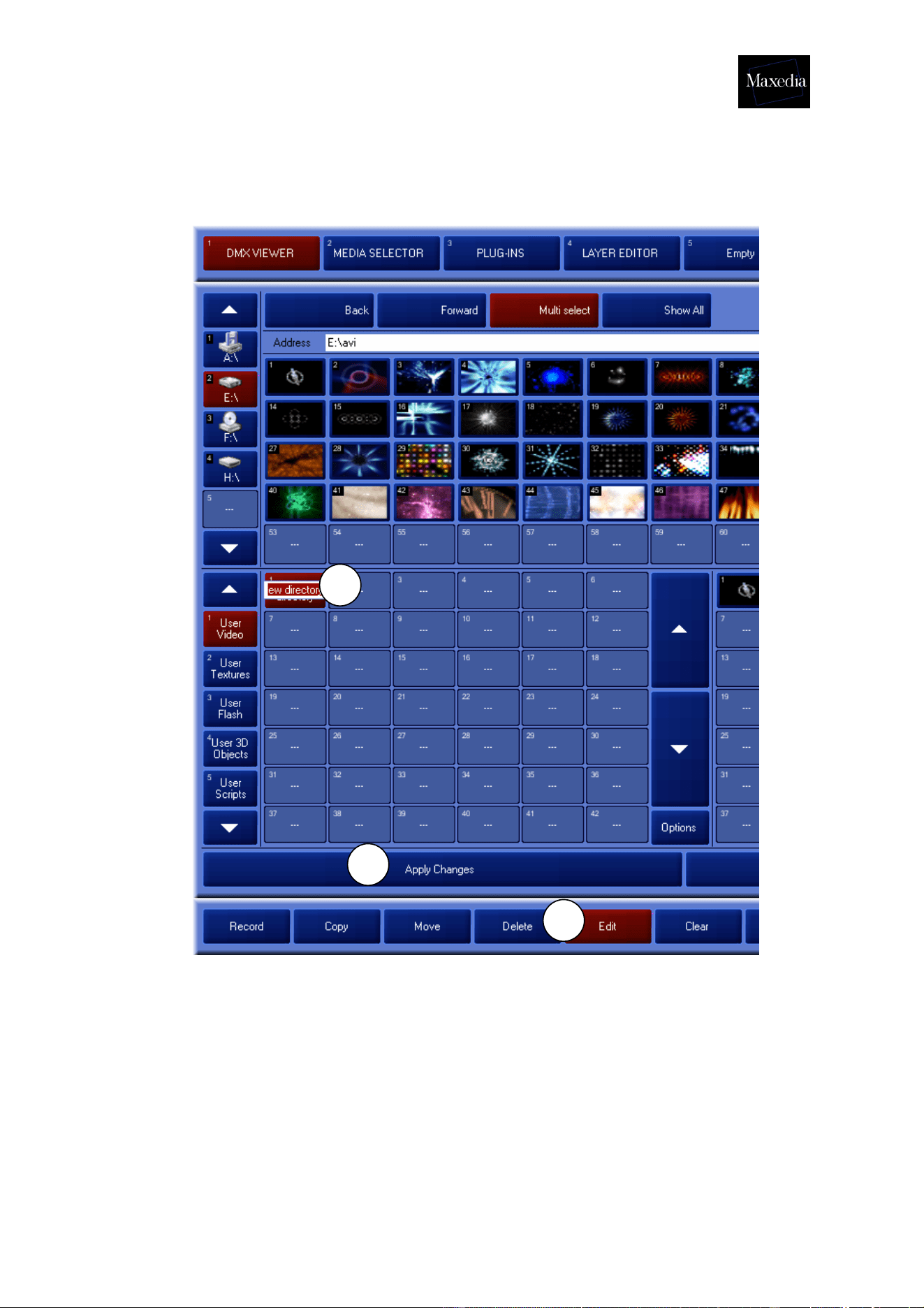
Now the show contains a folder with your own media. To give this folder a new name:
1. Click the Edit button in the Command bar.
2. Click the desired folder and fill in a new name.
3. To make sure the show contains the new media, you have to click the Apply
Changes button. The Maxedia will load all the new media to the hard drive,
where the show is stored.
1
2
3
Maxedia Manual
Version 2 38
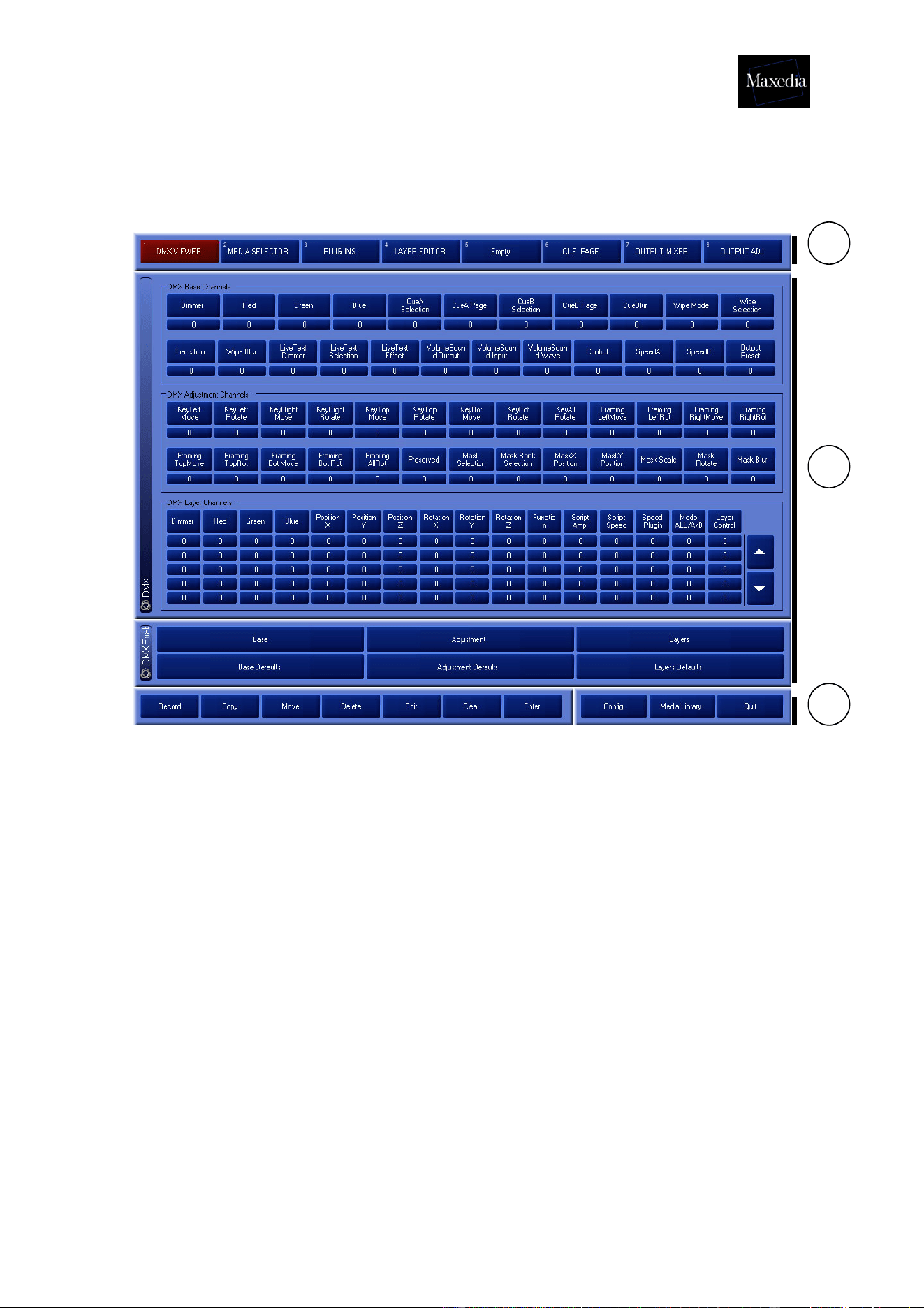
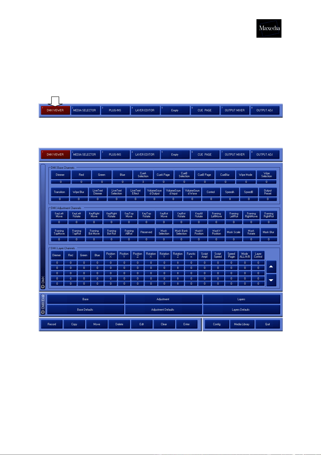
4.9. The DMX Viewer
The DMX Viewer is a special screen within Maxedia. It is generated by clicking the
Screen Selector button.
This is the DMX Viewer screen:
This special screen allows the user to constantly monitor all the commands sent from
the DMX to the Maxedia.
Maxedia Manual
Version 2 39
The DMX-viewer screen contains two panels:
• DMX: This panel gives an overview of all the DMX values used.
• DMX Base/Adjustment/Layers and DMX Base/Adjustment/Layers
Defaults: These panels are used to accept or reject DMX commands.
The Defaults will restore the original values.
! When DMX is accepted without a DMX signal entering, the output will remain black.
To repair it the Default buttons can be used.
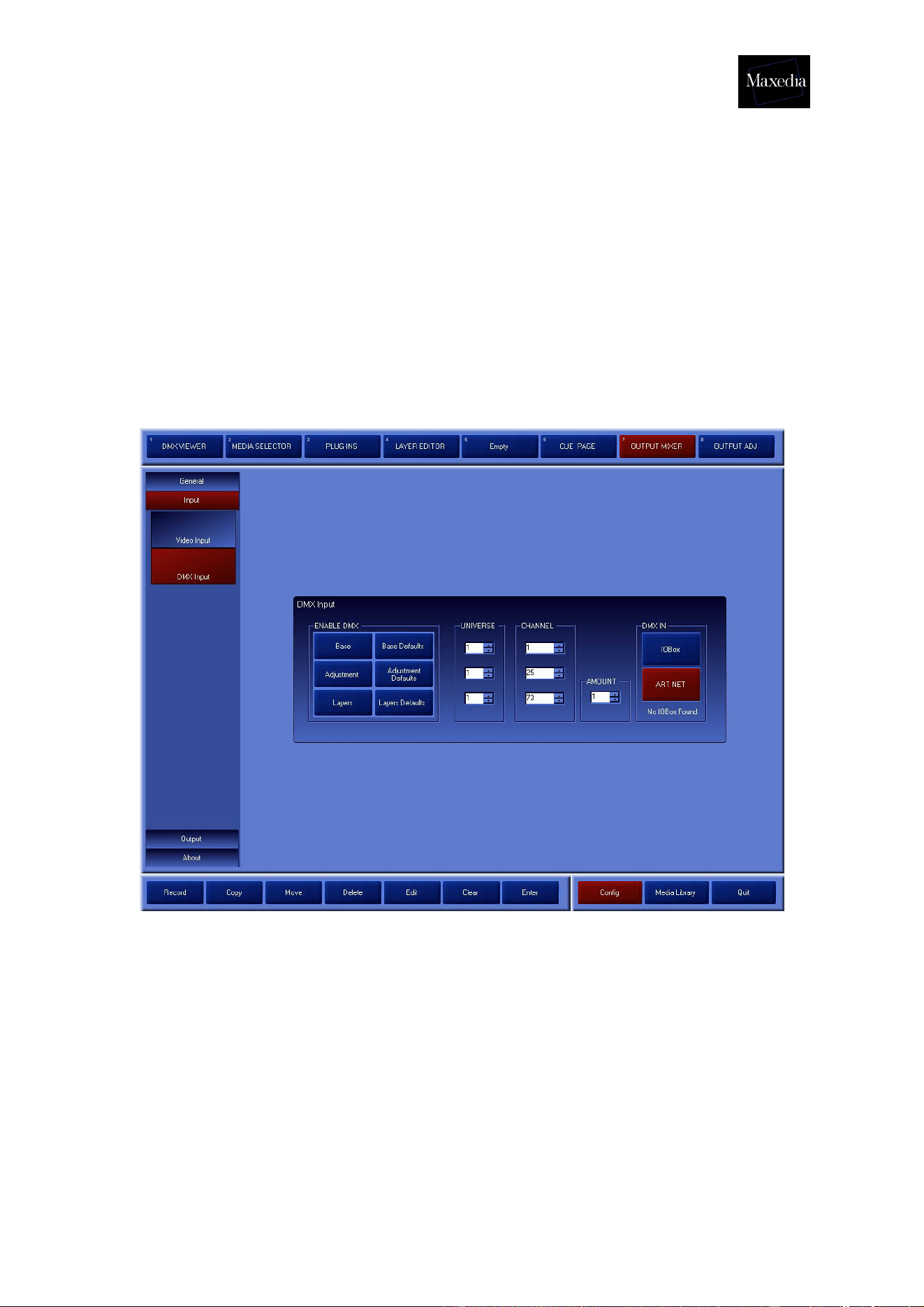
1. DMX Input can be used to adjust the DMX universes and channels by
which the Maxedia communicates with the lighting table. The
communication from the DMX to the Maxedia can be checked using the
DMX Viewer screen.
2. This is also possible via the IO-Box. Settings can be adjusted by the IO-
box (see appendix C).
! Maxedia is not always synchronised with the IO-Box. All changes in
the Maxedia software will be visible in the IO-Box and vice versa.
Maxedia Manual
Version 2 40
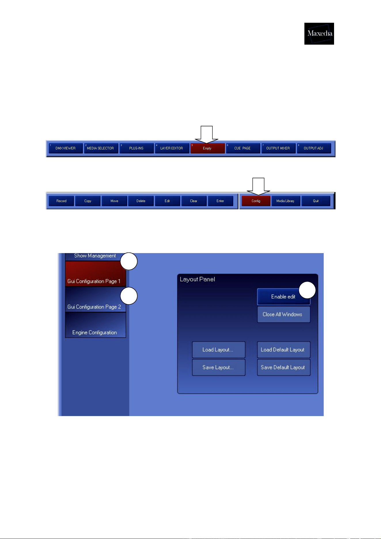
4.10. Determining the layout
The Maxedia can be customized to make it more user-friendly. You can create your
own main screens.
Go to Empty Page.
Choose Config in the Commandbar.
Follow the procedure described below to create a customized screen (see illustration
below):
1. Click Gui Configuration Page 1 button.
2. Click Enable edit button.
3. Click Gui Configuration Page 2 button.
1
2
3
Maxedia Manual
Version 2 41
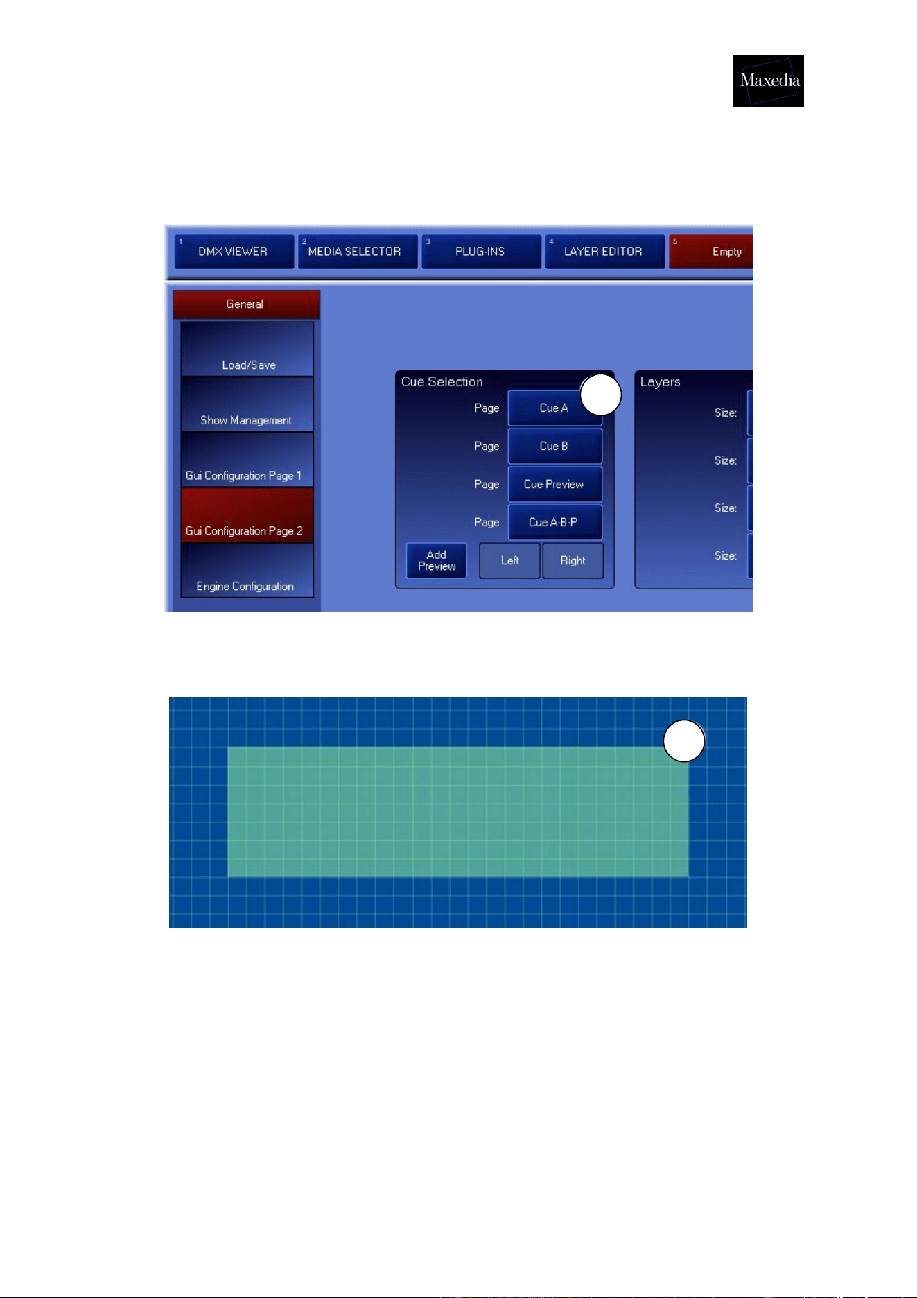
4. Click the Cue A button.
5. Click anywhere in the empty grid.
4
5
Maxedia Manual
Version 2 42
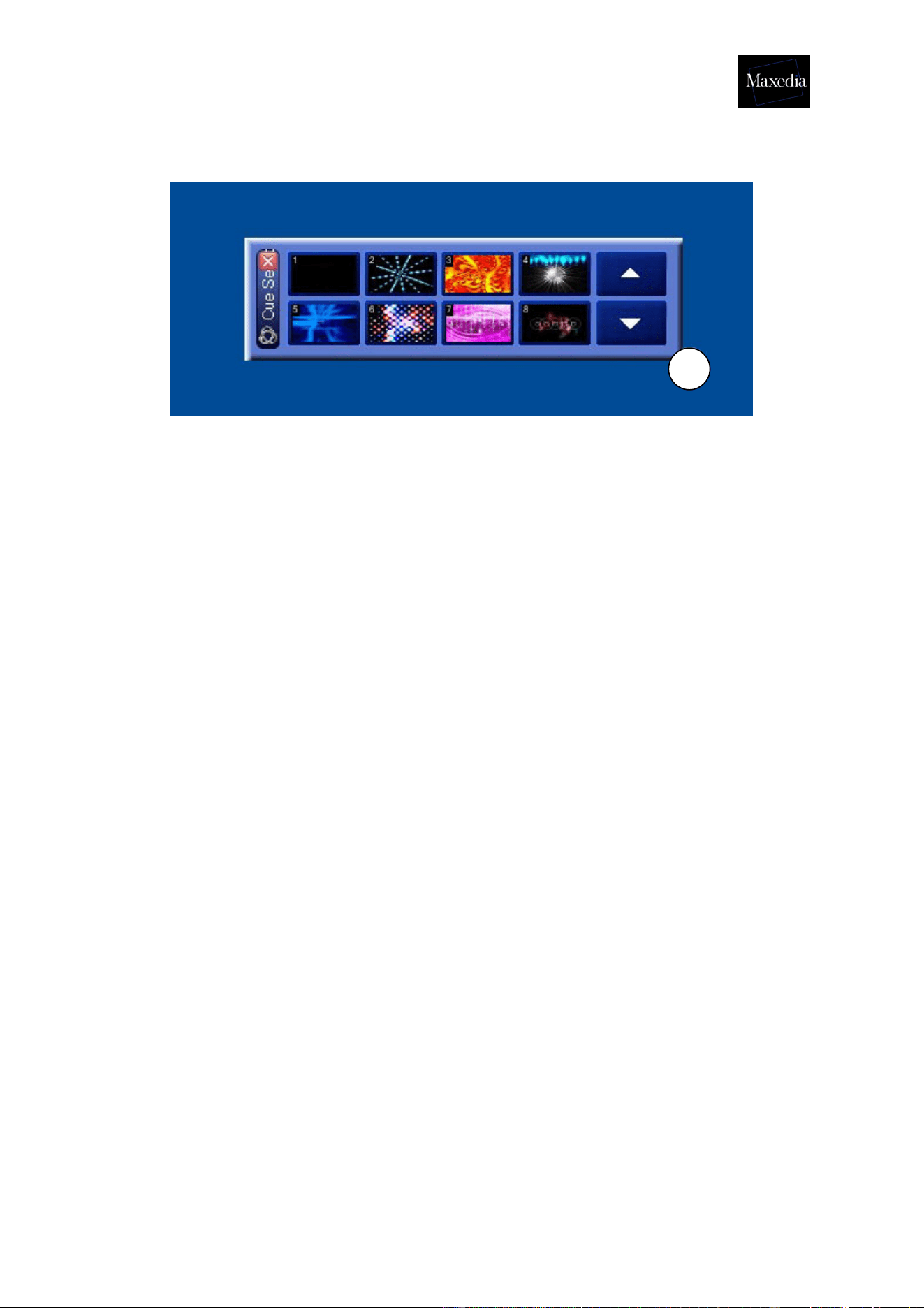
6. The Cue A screen appears. Click and drag the handle in the lower right
corner to make the screen larger or smaller.
Go back to the config-screen and click the Gui Configuration Page 1 button and the
Disable Edit button to store the layout.
7. Click the Save Default Layout button to keep the layout at the next
start-up.
To save the layout in a file, choose Save Layout.
6
Maxedia Manual
Version 2 43
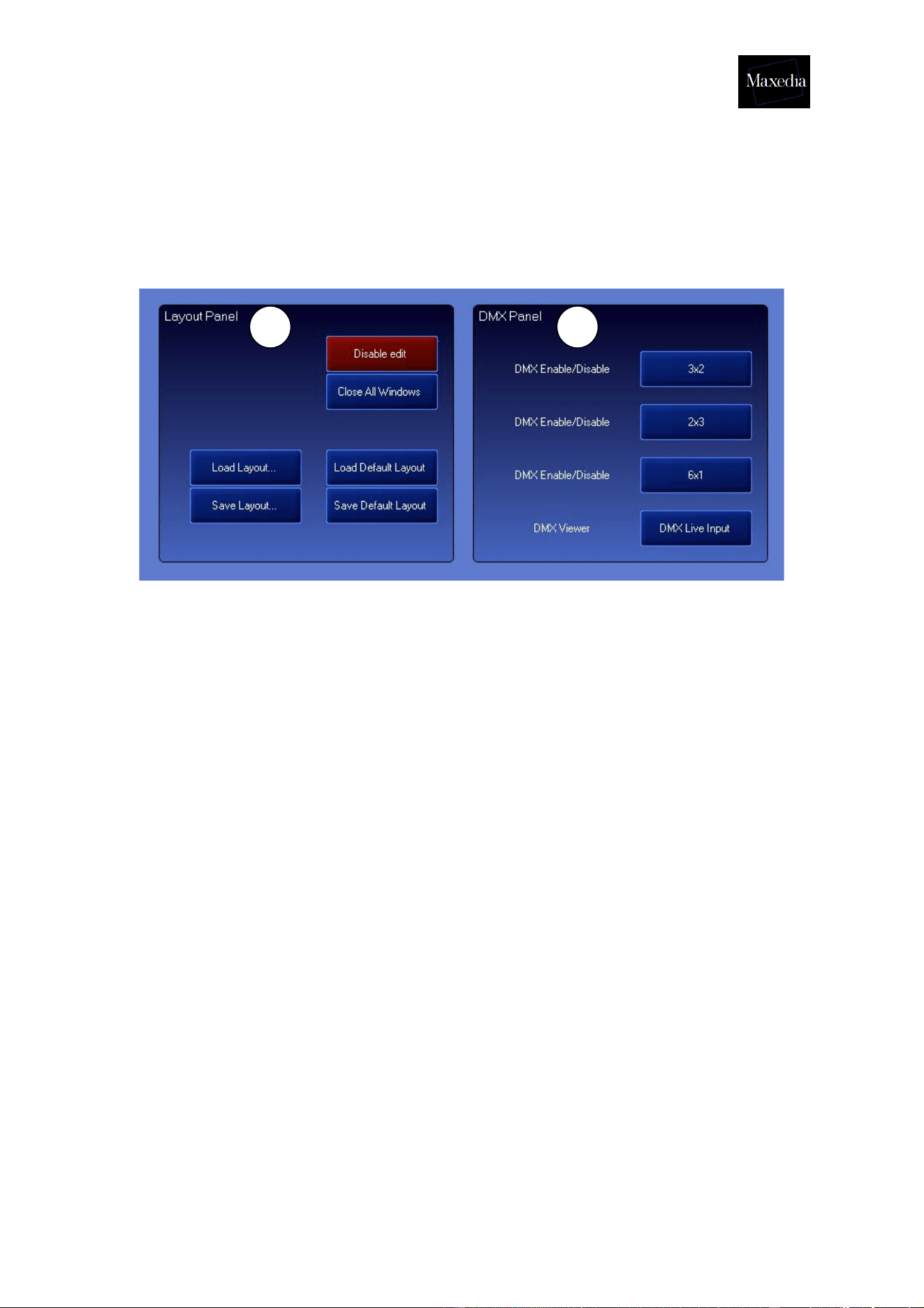
!
All screens can be added:
1. Gui Configuration Page 1
1. Layout Panel: This panel offers the possibility of (de)activating the
production of panels. It also enables the formed layout to be recalled or
saved.
2. DMX Panel: This panel allows buttons to be added to the layout which
enable the access to certain DMX channels.
1 2
Maxedia Manual
Version 2 44
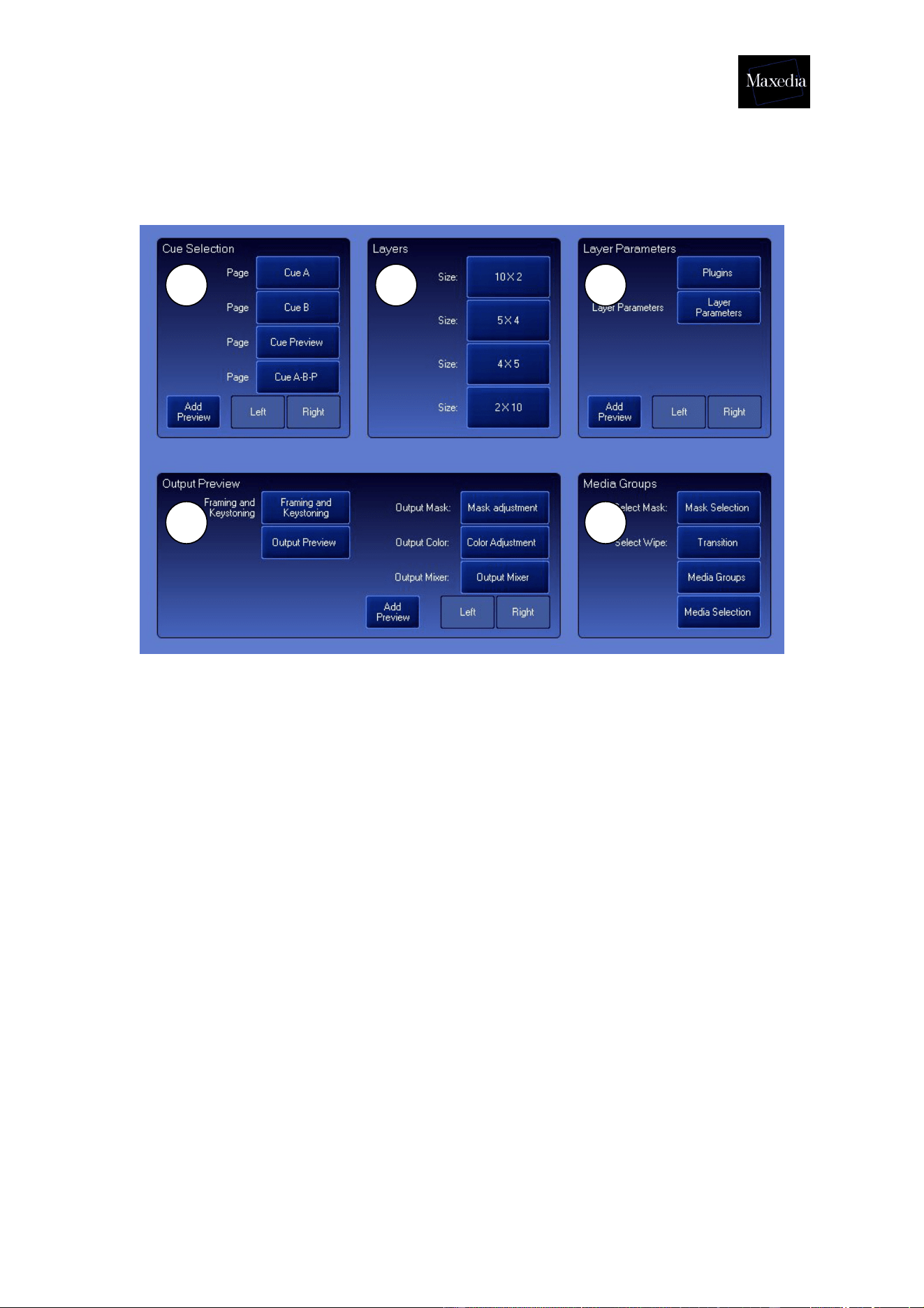
2. Gui Configuration Page 2
1. Cue Selection: Adds all cued-related panels.
2. Layers: Adds all kinds of layer panels.
3. Layer Parameters: Adds parameter panels concerning layers.
4. Output Preview: Allows creation of a screen that determines how
the output monitor will represent the cues.
5. Media Groups: Allows the creation of panels to browse through all
kinds of media.
1 2 3
4 5
Maxedia Manual
Version 2 45
Appendix A: Plugins
This appendix gives an overview of all the plug-ins.
A1. Video Plugin
This plug-in plays video and picture media.
Parameters:
- VIDEO In: Sets video start frame.
- VIDEO Out: Sets video stop frame.
- VIDEO Loop Mode: Determines whether the video
repeats from the beginning or stops on the last frame.
A2. Random Zoom Plugin
This plug-in zooms the video and picture media randomly.
Parameters:
- INTERVAL Interval: Determines whether the zoom
changes periodically.
- SCALING Scale X: Determines width (X-axis).
- SCALING Scale Y: Determines height (Y-axis).
- SCALING Scale Z: Determines depth (Z-axis).
- SCALING Keep Aspect: Determines whether or not
media should keep proportions during resizing.
A3. Smoke Plugin
This plug-in generates two-dimensional smoke.
Parameters:
- SMOKE smoke: Determines the amount of smoke.
Maxedia Manual
Version 2 46
A4. 2D Plasma Plugin
This plug-in generates two-dimensional plasma.
Parameters:
- No extra parameters
A5. 2D Fluid Plug-in
This plug-in generates a fluid effect which transforms the video
and picture media.
Parameters:
- FLUID Effects script: Determines the fluid effect.
- FLUID Amplitude: Determines the degree of the fluid
effect.
A6. 2D Particles Plugin
This plug-in generates a two-dimensional particle effect which
transforms the video and picture media into small fragments.
Parameters:
- OPTIONS Effect Script: Determines which script the
plug-in uses to generate the particles.
A7. 2D Text
This plug-in generates a two-dimensional text. It is possible to
work with the font and the size of your choice.
Maxedia Manual
Version 2 47
A8. 3D Ocean Plugin
This plug-in generates a three-dimensional ocean.
Parameters:
- WAVE Height: Determines the height of the waves.
- WAVE Wind: Determines the wind force.
- WAVE Suppression: Determines the flatness of the
waves.
- TEXTURE Texture: Determines the degree of the
texture.
- TEXTURE Fresnell: Determines the degree of the
Fresnell Shader
- TEXTURE Resolution: Determines the level of detail
shown in the texture.
- COLOR High RGB
- COLOR Low RGB
A9. 3D Tunnel Plugin
This plug-in generates three-dimensional tunnel effects.
Parameters:
- OPTIONS Direction: Determines the direction of the
camera.
- OPTIONS Depth 1: Determines the depth of the view.
- OPTIONS Depth 2: Determines the depth of the view.
- TUNNEL CAMERA Camera: Determines the type of
camera travelling through the tunnel.
- UV U: Determines the width of the texture in the tunnel.
- UV V: Determines the height of the texture in the tunnel.
Maxedia Manual
Version 2 48
A10. 3D Landscape Plugin
This plug-in generates a three-dimensional landscape effect.
Parameters:
- OPTIONS Distance: Determines how far the texture will
be stretched out over the landscape.
- OPTIONS Height: Determines the vertical size of the
landscape
- OPTIONS Fog: Determines the dipping of the horizon.
- TWIST Heading: Determines in which direction the
camera will travel.
- TWIST Bank: Determines the position of the camera
facing the horizon.
A11. 3D Ribbons Plugin
This plug-in generates a three-dimensional ribbon effect.
Parameters:
- OPTIONS Amount: Determines the visible amount of
ribbons.
- OPTIONS Shift: Determines the distance between
ribbons.
- OPTIONS Radius: Determines the proximity of ribbons
to the center.
- SHAPE Width: Determines the width of ribbons.
- SHAPE Height: Determines the height of ribbons.
- SHAPE Radius: Determines the length of ribbons.
A12. 3D Spikes Plugin
This plug-in generates a three-dimensional spikes effect.
Parameters:
- SHAPE Amount: Determines the amount of spikes.
- SHAPE Shape1: Determines the thickness of spikes.
- SHAPE Shape2: Determines the distance between the
centres of spikes.
- SHAPE Shape3: Determines the length of spikes.
Maxedia Manual
Version 2 49
A13. 3D Objects Plugin
This plug-in loads a three-dimensional object which has to be
*.x format.
Parameters:
- RIGHTHAND LEFT Righthand Left: Determines how
the object will be mirrored.
A14. 3D Blob Plugin
This plug-in generates a three-dimensional blob effect.
Parameters:
- SHAPE Shape 1: Determines the transformation of the
star.
- SHAPE Shape 2: Determines the transformation of the
vertical disc.
- SHAPE Shape 3: Determines the transformation of the
horizontal disc.
Maxedia Manual
Version 2 50
Appendix B: The Configuration screen
The Maxedia-settings can be changed via the configuration screen.
Choose Config in the Command bar.
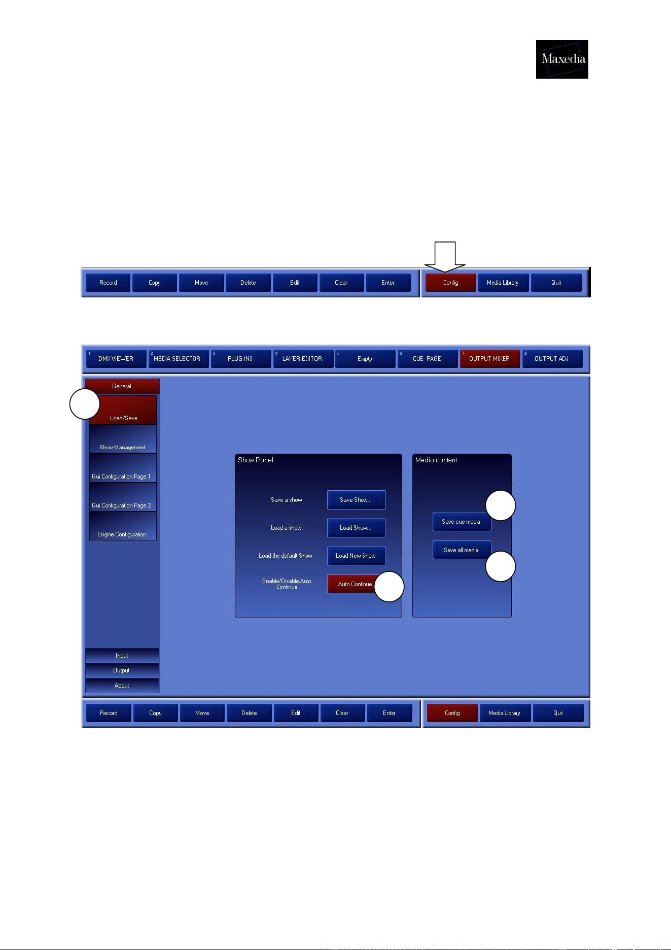
! While restarting Maxedia, the Load Show-button gives also access to Load/Save
or Show Management.
a) Load/Save
Load/Save can be used to save a whole show in one MX Show file. Normally, the
media are not saved, but this can be changed by using Save Cue Media and Save
All Media (see illustration above).
1. Save Cue Media: This offers the possibility of saving the media content of
the cues.
2. Save All Media: This offers the possibility of saving all media, including the
ones that were not used in the cues.
a
1
2
!

Maxedia Manual
Version 2 51
! The MX Show files can become very large, depending on the media used in the
show.
! The Auto Continue button supplies an automatic restart after 30 seconds (see !
illustration on previous page).
Maxedia Manual
Version 2 52
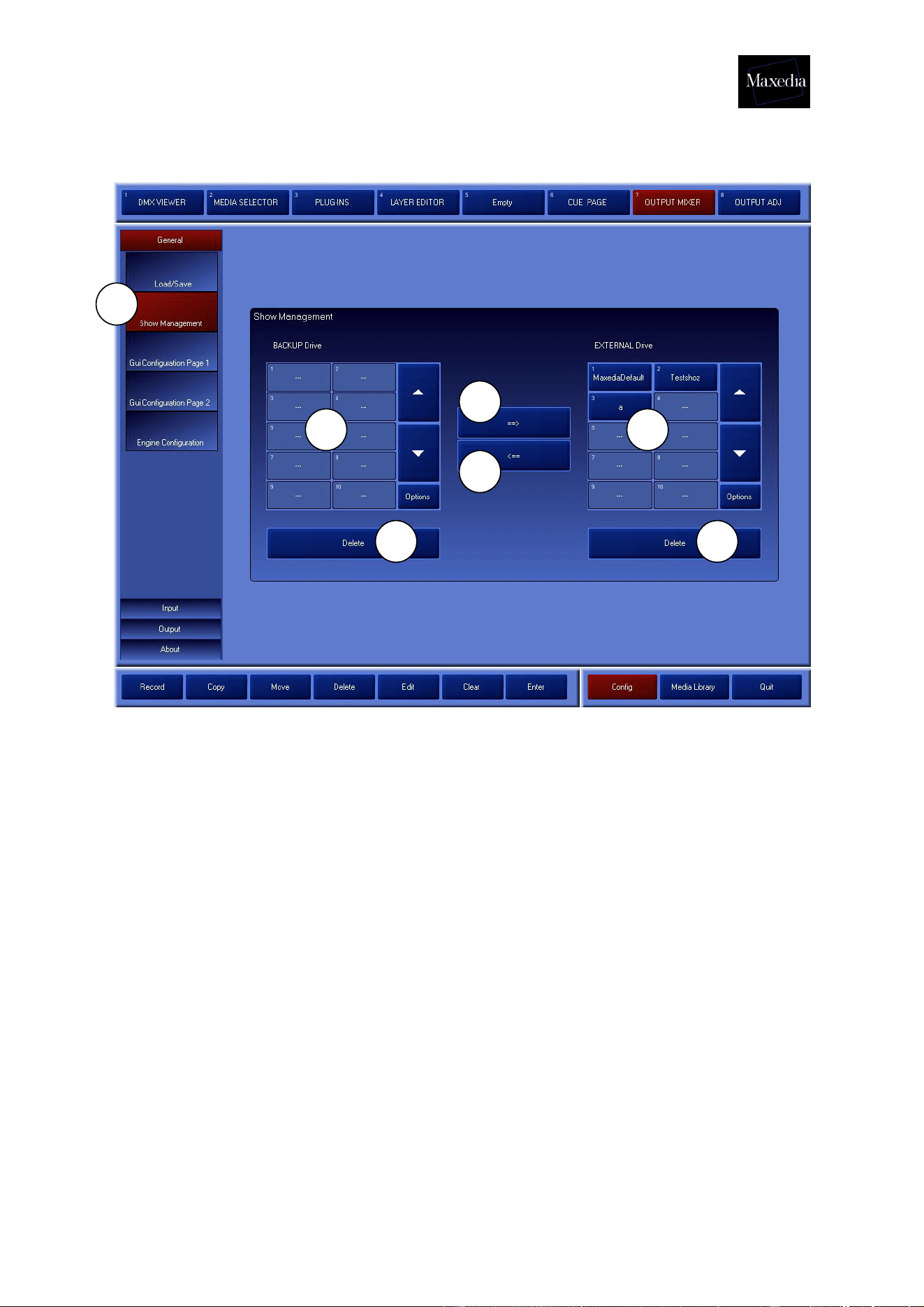
b) Show Management
Back-ups can be made via Show Management by copying shows from the External
Drive to the BackUp Drive (see illustration above).
1. BackUp Drive (D:\)
2. External Drive (E:\): Loading shows is only possible when the shows are on
the External Drive.
3. This offers the possibility of moving a selected show from the BackUp Drive to
the External Drive. Maxedia will ask if the existing show may be overwritten.
4. This offers the possibility of moving a selected show from the External Drive to
the BackUp Drive. Maxedia will ask if the existing show may be overwritten.
5. The shows can be deleted from both drives by using the Delete buttons.
NOTE! This is a dangerous action. The entire show will be deleted.
! All media will be saved. Consequently, the saving-process may take a while.
b
1 2
3
4
5 5
Maxedia Manual
Version 2 53
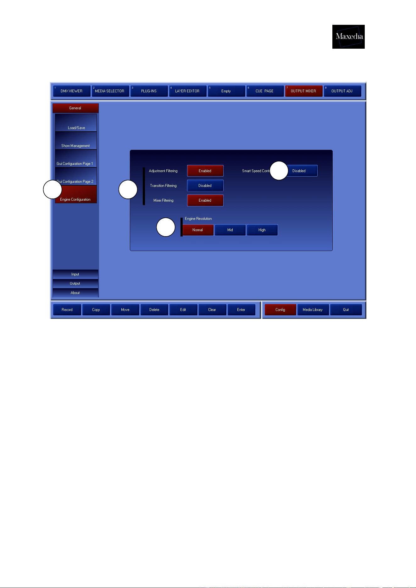
c) Engine Configuration
Engine Configuration allows the engine of the software to be set (see illustration
above).
1. Engine Filtering options: Allow setting of Output-filters.
2. Engine Resolution: Allow setting of Engine-resolutions.
• Normal: 512 pixels x 512 pixels
• Mid: 1024 pixels x 512 pixels
• High: 1024 pixels x 1024 pixels
3. Smart Speed Control: If this option is switched on, the speed of cue B will be
reduced to zero whenever only cue A is visible.
1
2
3
c
Maxedia Manual
Version 2 54
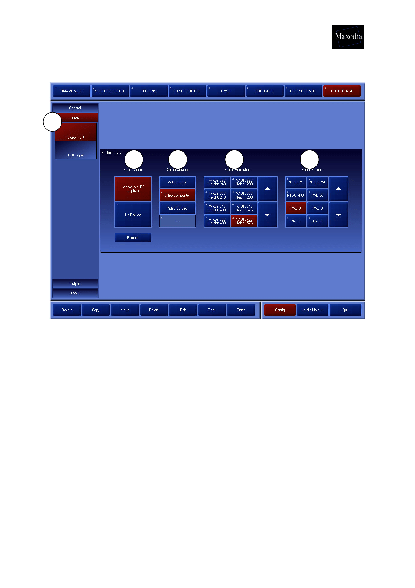
d) Video Input
The screen above will be generated by clicking the Input button and the Video Input
button. It contains the following elements (see illustration above):
1. Select Video: These devices can be connected by USB/FireWire/Analog
Format.
3. VideoMate TV Capture: Video 1 In (will be detected automatically)
4. No Device: Video 2 In (will be detected automatically)
2. Select Source: Here the video source can be selected.
3. Select Resolution: Here the desired resolution can be selected.
4. Select Format: Here the desired standard can be selected.
d
1 2 3 4

Maxedia Manual
Version 2 55
Appendix C: DMX Layout
Maxedia Base fixture layout 24 Channels
Standard DMX Channels
1. Dimmer
2. Red
3. Green
4. Blue
5. Cue Selection
6. Cue Page
7. Cue B Selection (A/B Mode)
8. Cue B Page
9. Cue Blur
10. Transition / Wipe Mode
11. Transition / Wipe Selection
12. Transition
13. Transition Fine
14. Wipe Blur
15. Live-Text Dimmer
16. Live-Text Selection
17. Live-Text Effect
18. Volume Sound Output
19. Volume Sound Input
20. Volume Sound Wav
21. Control (Test Images)
22. Speed A
23. Speed B
24. Output Preset

Maxedia Manual
Version 2 56
Key to channels:
• Channel 1 Dimmer for the Output: Default = 256; Fade
• Channel 2. Red Default = 128; Fade
Value 0- 127 = Black to Red
Value 128 = Normal
Value 129-255 = Red to White
• Channel 3 Green. Default = 128; Fade
Value 0- 127 = Black to Green
Value 128 = Normal
Value 129-255 = Green to White
• Channel 4 Blue. Default = 128; Fade
Value 0- 127 = Black to Blue
Value 128 = Normal
Value 129-255 = Blue to White
Cue Selection
• Channel 5 Cue selection. Default = 0; Snap
Value 0 = Blackout
Value 1 = Cue 1
…
Value 255 = Cue 255
• Channel 6 Cue Page. Default = 0; Snap
Value 0 -1 = Cue Page 1
Value 2 = Cue Page 2
…
Value 255 = Cue Page 255
• Channel 7 Cue selection B. Default = 0; Snap
Value 0 = Blackout
Value 1 = Cue 1
…
Value 255 = Cue 255
• Channel 8 Cue Page B. Default = 0; Snap
Value 0-1 = Cue Page 1
Value 2 = Cue Page 2
…
Value 255 = Cue Page 255
• Channel 9 Cue Blur. Default= 0; Fade Value 0-255 = No Blur to Full Blur

Maxedia Manual
Version 2 57
Transition & Wipe Channels
• Channel 10 Transition / Wipe Mode. Default = 0; Snap
Value 0 = Transition
Value 1 = Wipe Bank 1
…
Value 255= Wipe Bank 255
• Channel 11 Transition / Wipe selection. Default =0; Snap
Value 0 -1= Transition / Wipe 1
Value 2 = Transition / Wipe 2
…
Value 255 = Transition / Wipe 255
• Channel 12 & 13: 16 bit ‘Transition’. Default = 0; Fade
Channel 12 = MSB
Channel 13 = LSB
• Channel 14 Wipe Blur. Default = 128; Fade
Live Text Channels
• Channel 15 Live-Text Dimmer. Default = 0; Fade
• Channel 16 Live-Text selection. Default = 0; Snap
Not implemented
• Channel 17: Live-Text Effect. Default = 0; Snap
Not implemented
Audio Volume
• Channel 18: Audio Volume OUT. Default = 100; Fade
• Channel 19: Audio Volume IN. Default = 0; Fade
• Channel 20: Audio Volume WAV. Default = 100; Fade

Maxedia Manual
Version 2 58
Global
• Channel 21 Output Mode. Default = 0; Snap
Value 0-4 = Default Maxedia Output
Value 5-9 = Color Bar
Value 10-14 = Staircase
Value 15 -19 = Alignment
Value 20-24 = Video In 1
Value 25-29 = Video In 2
Value 30-255 = Not used
• Channel 22: Speed A Default = 128; Fade
• Channel 23: Speed B Default = 128; Fade
• Channel 24 Output Preset Selection Default = 0; Snap
Value 0 = No Preset, DMX override
Value 1 = Preset 1
…
Value 255 = Preset 255

Maxedia Manual
Version 2 59
Maxedia DMX Layer 22 channels
Standard DMX Channels
25. Dimmer
26. Red
27. Green
28. Blue
29. Position X
30. Position X Fine
31. Position Y
32. Position Y fine
33. Position Z
34. Position Z fine
35. Rotation X
36. Rotation X Fine
37. Rotation Y
38. Rotation Y fine
39. Rotation Z
40. Rotation Z fine
41. Function
42. Script Amplitude
43. Script Speed
44. Speed Plug-in
45. Mode All/A/B
46. Layer control

Maxedia Manual
Version 2 60
Key to channels:
Dimmer channels / RGB
• Channel 1 Dimmer for the Layer: Default = 256; Fade
• Channel 2. Red Default = 128; Fade
Value 0- 127 = Black to Red
Value 128 = Normal
Value 129-255 = Red to White
• Channel 3 Green. Default = 128; Fade
Value 0- 127 = Black to Green
Value 128 = Normal
Value 129-255 = Green to White
• Channel 4 Blue. Default = 128; Fade
Value 0- 127 = Black to Blue
Value 128 = Normal
Value 129-255 = Blue to White
Position/Rotation
• Channel 5 & 6: 16 bit ‘Position X’. Default = 32768; Fade
Channel 5 = MSB
Channel 6 = LSB
Value 0-16383 = Position ACLK
Value 16384-49151 = Positioning
Value 49152-65535 = Position CLK
• Channel 7 & 8: 16 bit ‘Position Y’. Default = 32768; Fade
Channel 7 = MSB
Channel 8 = LSB
Value 0-16383 = Position ACLK
Value 16384-49151 = Positioning
Value 49152-65535 = Position CLK
• Channel 9 & 10: 16 bit ‘Position Z’. Default = 32768; Fade
Channel 9 = MSB
Channel 10= LSB
Value 0-16383 = Position ACLK
Value 16384-49151 = Positioning
Value 49152-65535 = Position CLK

Maxedia Manual
Version 2 61
• Channel 11 & 12: 16 bit ‘Rotation X’. Default = 32768; Fade
Channel 11 = MSB
Channel 12 = LSB
Value 0-16383 = Rotate ACLK
Value 16384-49151 = Positioning
Value 49152-65535 = Rotate CLK
• Channel 13 & 14: 16 bit ‘Rotation Y’. Default = 32768; Fade
Channel 13 = MSB
Channel 14 = LSB
Value 0-16383 = Rotate ACLK
Value 16384-49151 = Positioning
Value 49152-65535 = Rotate CLK
• Channel 15 & 16: 16 bit ‘Rotation Z’. Default = 32768; Fade
Channel 15 = MSB
Channel 16 = LSB
Value 0-16383 = Rotate CLK
Value 16384-49151 = Positioning
Value 49152-65535 = Rotate ACLK
• Channel 17: Function (Reserved). Default = 0, Snap
• Channel 18: Script Amplitude. Default = 0; Fade
• Channel 19: Script Speed. Default = 128, Fade
• Channel 20: Speed Plug-in. Default = 128, Fade
Value 0-120 = Speed 0 to Normal Speed
Value 121-139 = Normal Speed
Value 140-255 = Normal Speed to Fast
• Channel 21: Mode All /A /B. Default = 0; Snap
Value 0-63 = Normal (Layer A & B)
Value 64-127 = A Layer Only
Value 128-191 = B Layer only
Value 192-255 = Preview Layer only
• Channel 22: DMX override OFF/ON. Default = 0, Snap
Value 0 = OFF
Value 1 = Layer 1 Override
Value 2 = Layer 2 Override
Value 3 = Layer 3 Override
Value 4 = Layer 4 Override
Value 5 = Layer 5 Override
Value 6 = Layer 6 Override
Value 7 = Layer 7 Override
Value 8 = Layer 8 Override

Maxedia Manual
Version 2 62
Value 9 = Layer 9 Override
Value 10 = Layer 10 Override
Value 11 = Layer 11 Override
Value 12 = Layer 12 Override
Value 13 = Layer 13 Override
Value 14 = Layer 14 Override
Value 15 = Layer 15 Override
Value 16 = Layer 16 Override
Value 17 = Layer 17 Override
Value 18 = Layer 18 Override
Value 19 = Layer 19 Override
Value 20-255 = Layer 20 Override

Maxedia Manual
Version 2 63
Maxedia DMX Output Adjustment 48 channels
1. KeyStone Left Move
2. KeyStone Left Move Fine
3. KeyStone Left Rotate
4. KeyStone Left Rotate Fine
5. KeyStone Right Move
6. KeyStone Right Move Fine
7. KeyStone Right Rotate
8. KeyStone Right Rotate Fine
9. KeyStone Top Move
10. KeyStone Top Move Fine
11. KeyStone Top Rotate
12. KeyStone Top Rotate Fine
13. KeyStone Bottom Move
14. KeyStone Bottom Move Fine
15. KeyStone Bottom Rotate
16. KeyStone Bottom Rotate Fine
17. KeyStone ALL Rotate
18. KeyStone ALL Rotate Fine
19. Framing Left Move
20. Framing Left Move Fine
21. Framing Left Rotate
22. Framing Left Rotate Fine
23. Framing Right Move
24. Framing Right Move Fine
25. Framing Right Rotate
26. Framing Right Rotate Fine
27. Framing Top Move
28. Framing Top Move Fine
29. Framing Top Rotate
30. Framing Top Rotate Fine
31. Framing Bottom Move
32. Framing Bottom Move Fine
33. Framing Bottom Rotate
34. Framing Bottom Rotate Fine
35. Framing All Rotate
36. Framing All Rotate Fine
37. Not used
38. Mask Selection
39. Mask Selection Fine
40. Mask X Position
41. Mask X Position Fine
42. Mask Y Position
43. Mask Y position Fine
44. Mask Scale
45. Mask Scale Fine
46. Mask Rotate
47. Mask Rotate Fine
48. Framing/Mask Blur

Maxedia Manual
Version 2 64
Key to channels:
• Channel 1 & 2: 16 bit ‘Keystone Left Move’. Default = 0; Fade
Channel 1 = MSB
Channel 2= LSB
• Channel 3 & 4: 16 bit ‘Keystone Left Rotate’. Default = 32768; Fade
Channel 3 = MSB
Channel 4= LSB
• Channel 5 & 6: 16 bit ‘Keystone Right Move’. Default = 0; Fade
Channel 5 = MSB
Channel 6= LSB
• Channel 7 & 8: 16 bit ‘Keystone Right Rotate’. Default = 32768; Fade
Channel 7 = MSB
Channel 8= LSB
• Channel 9 & 10: 16 bit ‘Keystone Top Move’. Default = 0; Fade
Channel 9 = MSB
Channel 10= LSB
• Channel 11 & 12: 16 bit ‘Keystone Top Rotate’. Default = 32768; Fade
Channel 11 = MSB
Channel 12= LSB
• Channel 13 & 14: 16 bit ‘Keystone Bottom Move’. Default = 0; Fade
Channel 13 = MSB
Channel 14= LSB
• Channel 15 & 16: 16 bit ‘Keystone Bottom Rotate’. Default = 32768; Fade
Channel 15 = MSB
Channel 16= LSB
• Channel 17 & 18: 16 bit ‘KeyStone All Rotate’. Default = 32768; Fade
Channel 17 = MSB
Channel 18= LSB
• Channel 19 & 20: 16 bit ‘Framing Left Move’. Default = 0; Fade
Channel 19 = MSB
Channel 20= LSB
• Channel 21 & 22: 16 bit ‘Framing Left Rotate’. Default = 32768; Fade
Channel 21 = MSB
Channel 22= LSB

Maxedia Manual
Version 2 65
• Channel 23 & 24: 16 bit ‘Framing Right Move’. Default = 0; Fade
Channel 23 = MSB
Channel 24 = LSB
• Channel 25 & 26: 16 bit ‘Framing Right Rotate’. Default = 32768; Fade
Channel 25 = MSB
Channel 26= LSB
• Channel 27 & 28: 16 bit ‘Framing Top Move’. Default = 0; Fade
Channel 27 = MSB
Channel 28= LSB
• Channel 29 & 30: 16 bit ‘Framing Top Rotate’. Default = 32768; Fade
Channel 29 = MSB
Channel 30= LSB
• Channel 31 & 32: 16 bit ‘Framing Bottom Move’. Default = 0; Fade
Channel 31 = MSB
Channel 32= LSB
• Channel 33 & 34: 16 bit ‘Framing Bottom Rotate’. Default = 32768; Fade
Channel 33 = MSB
Channel 34= LSB
• Channel 35 & 36: 16 bit ‘Framing Rotation’. Default = 32768; Fade
Channel 35 = MSB
Channel 36= LSB
• Channel 37 ‘Not Used’. Default 0; Snap
• Channel 38 Mask selection. Default =0; Snap
Value 0 = No Mask
Value 1 = Mask 1
…
Value 255= Mask 255
• Channel 39 Mask Bank selection. Default =0; Snap
Value 0-1 = Bank 1
Value 2 = Bank 2
…
Value 255 = Bank 255
• Channel 40 & 41 Mask X Position. Default = 32768; Fade
Channel 40= MSB
Channel 41= LSB

Maxedia Manual
Version 2 66
• Channel 42 & 43 Mask Y Position. Default = 32768; Fade
Channel 42 = MSB
Channel 43 = LSB
• Channel 44 & 45 Mask Scale. Default =32768; Fade
Channel 44 = MSB
Channel 45 = LSB
• Channel 46 & 47 Mask Rotation. Default = 32768; Fade
Channel 46 = MSB
Channel 47 = LSB
• Channel 48 Mask Blur. Default= 32; fade Value 0-255 = No blur to Full Blur

Martin Professional A/S " Olof Palmes Allé 18 " 8200 Aarhus N " Denmark
http://www.martin.com
The Maxedia forum is available at http://www.martin.com/forum