
Read this operation manual before using the product.
Zoom Lens
CN20x50
OPERATION MANUAL " Lens "
ENG

Memo

ENGLISH VERSION

Memo
-
FOREWORD
-
Thank you for purchasing the Canon zoom lens.
This product comes with the following documents for the models mentioned below:
• Operation Manual "Before Using The Product"
(
Included with the product
)
• Operation Manual "Regulations"
(
Included with the product
)
• Operation Manual "Lens"
(
Web
)
• Operation Manual "Information display"
(
Web
)
• Quick guide "Information display"
(
Web
)
• Depth-of-eld
(
Web
)
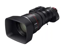
Make sure all of the following items are included in the packing box. If you nd any item missing, please
contact your dealer or Canon Inc.
Accessories other than those mentioned above may be required depending on the specications of your unit.
For details, contact your dealer or Canon Inc.
Two types such as the EF mount and the PL mount are available for this product. Illustrations in this manual are for
the EF mount lens unless otherwise mentioned.
PRODUCT LIST
Hood cap
Hood
Operation Manual
"
Regulations
"
Operation Manual
"Before Using The Product"
Lens cap
Dust cap
Lens body
Drive unit
storage bag
Attachment holder
Drive unit xing
screws (x3)
CN20x50 IAS H/E1
(
EF Mount
)
CN20x50 IAS H/P1
(
PL Mount
)
GENERAL SAFETY INFORMATION
The safety warnings and cautions provided on the product or in this operation manual must be observed.
Failure to observe these warnings and cautions may result in injury or accident.
Read this operation manual carefully to familiarize yourself with its contents and ensure that you can operate the
product properly.
Also, store this manual in a safe place where it can easily be referenced whenever necessary.
This operation manual uses the following symbols and terms to identify hazards in order to prevent accidents.
WARNING
This indicates a potentially hazardous situation which, if not heeded, may result in
death or serious injury to you or others. Be sure to heed all warning notices to en-
sure safe operation at all times.
CAUTION
This indicates a potentially hazardous situation which, if not heeded, may result in a
minor injury to you or others, or damage to property.
NOTE
This indicates cautions and recommendations for operation. It contains information
which, if not heeded, may result in this product failing to function properly.
These notices also contain useful information for operation.
HANDLING THE PRODUCT
WARNING
1. Do not get this product wet or allow liquid inside. If water gets inside, stop using the product immediately. Continuing to
use the product under this condition may cause a re or electric shocks.
2. Do not stare at the sun or other bright objects through the lens. It may injure your eyes.
3. Be sure to hold the connector when disconnecting the cable. Pulling on the cable may sever or damage it and pose a
risk of a re or electric shocks from a short circuit.
CAUTION
1. Be careful not to drop the product when carrying it. Dropping the product may cause injury.
2. Ensure that all mountings are securely tightened. If a mounting becomes loose, parts may fall o and cause injury.
3. Inspect mountings regularly (about every six months to one year) to ensure they are securely tightened. If a mounting
becomes loose, parts may fall o and cause injury.
4. When this product is used under a blazing sun, the inside of the unit may be heated to high temperature. When
it is expected that the unit is exposed to elevated temperature, take measures against heat as appropriate on the
customer’s side.
NOTE
1. Striking or dropping the lens may cause the malfunction of the product.
2. This product is not waterproof. Take measures to avoid direct contact with rain, snow, or moisture. Otherwise it may
cause the malfuction of the product.
3. In dusty environments, cover the lens mount when using, attaching or removing the lens. If dust enters inside, it may
cause the malfunction of the product.
4. Take measures to avoid sudden changes in temperature where the lens is used, which may prevent operation
temporarily if condensation forms in the lens.
5. Before use in particular environments, such as places where chemical products are used, contact your Canon sales
representative or dealer. Using in particular environments may cause the malfunction of the product.

DEALING WITH ABNORMALITIES
WARNING
Should any of the abnormalities described below occur, immediately dismount the lens from the camera and contact
your Canon sales representative or dealer.
• Smoke, fumes, or unusual noises
• Entry of foreign objects (such as liquid or metal objects) inside the product
MAINTENANCE AND INSPECTION
WARNING
Be sure to disconnect the cable and remove the lens from the camera before cleaning outside of the lens. Do not use
benzene, thinner, or other ammable substances to clean the product. Otherwise it may cause a re or electric shocks.
NOTE
1. Clean o any dust on the lens surface using a lens blower or a soft lens brush. In case of getting ngerprints or stains
on the lens, use a clean cotton cloth moistened with commercial lens cleaning uid, or use lens cleaning paper. Gently
wipe in a spiral pattern from the center of the lens. Be careful not to rub dust across the lens, which may scratch the
lens surface
2. Routine inspection about once a year is recommended, depending on the conditions and environment of use. Request
overhaul, if needed.
STORAGE
CAUTION
Always attach the lens cap, hood cap, dust cap or covers before storage. Storing the lens without the caps or covers
attached poses a risk of re if the lens concentrate light in direct sunlight.
NOTE
1. Immediately wipe o any moisture on the lens from misty or foggy environments, using a dry cloth. Seal the lens in
a plastic bag with a desiccant (preferably new) to prevent moisture inside. Otherwise it may cause the mold or the
malfunction of the product.
2. Before using the product with the separately available carrying case, contact your Canon sales representative or dealer.
Components such as adhesives used in the carrying case may have an adverse eect on the product.
TO THE CUSTOMER
1. Canon shall bear no responsibility for damage resulting from improper operation of this product by the customer.
2. Canon shall make no guarantees about the product quality, functions, or operation manual and its marketability and
suitability for the customer’s purpose.
Moreover, Canon shall bear no responsibility for any damage, direct or incidental, that results from usage for the
customer’s purpose.
3. The product specications, conguration, and appearance are subject to change without prior
notice.
4. For further information on repairs, maintenance, or adjustments not mentioned in this operation manual, contact your
Canon sales representative or dealer.
5 Note that Canon may be unable to undertake servicing or repair of a product if it is modied without consulting Canon
or your Canon sales representative.
The copyright for this manual is retained by Canon Inc.
Unauthorized copying or reproduction in whole or part is prohibited.

Memo

E1
1 NOMENCLATURE
E2
2 HOW TO MOUNT
E3
3 ADJUSTMENT
E7
5 OPERATION
E10
6 HOW TO ATTACH
AND DETACH THE
DRIVE UNIT
E19
E24
2-1. MOUNT THE LENS ON THE CAMERA
2-2. MOUNT THE HOOD ON THE LENS
2-3. TURN IT ON
2-4. AVAILABLE ACCESSORIES
2-5. DIMENSIONS OF PARTS
3-1.
BACK FOCUS ADJUSTMENT OF THE LENS
3-2. IRIS GAIN ADJUSTMENT
5-1. ZOOM OPERATION
5-2. FOCUS OPERATION
5-3. IRIS OPERATION
5-4. EXTENDER OPERATION
5-5. MACRO OPERATION
5-6. SWITCH OPERATIONS
6-1. HOW TO DETACH THE DRIVE UNIT
6-2. HOW TO ATTACH THE DRIVE UNIT
6-3. AUTOMATIC ADJUSTMENT OF
THE MECHANICAL END
4 MODE SETTING
E8
4-1. OPERATION MODES
4-2. SETTINGS IN BASIC MODE
4-3. SETTINGS IN FULL MODE
4-4. SETTINGS IN ANALOG MODE
7 PRODUCT
SPECIFICATIONS
APPENDIXES
END
TECHNICAL INFORMATION
E2
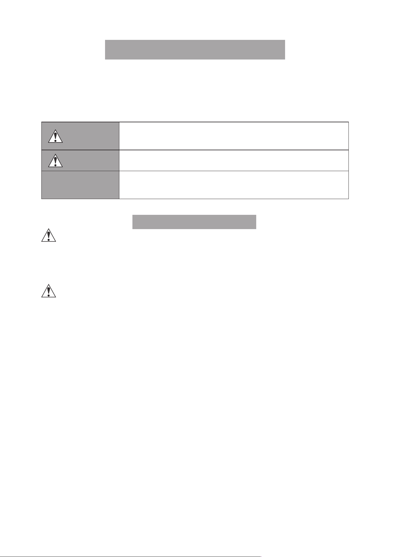
①
Iris Gain Adjusting Trimmer
②
Focus Ring A
③
Focus Ring B
④
Max. Zoom Speed Adjusting Volume
⑤
Instant Auto-Iris Switch
⑥
Iris Operation Mode Change-over Switch
⑦
Zoom Rocker Seesaw
⑧
RET Switch (Video Return Switch)
⑨
VTR Switch
⑩
AUX
Switch
⑪
Flange Back Lock Screw
⑫ Flange Back Adjusting Ring
⑬
Macro Ring
⑭ Macro Button
⑮
Extender Switching Lever
⑯
MEMO Switch (Memory Switch)
⑰
Iris Ring
⑱
Zoom Ring
⑲ Zoom Lever
⑳
Lens Holder
㉑
Attachment Holder Contact Plate
㉒
Tie Cable
㉓
Remote Connectors (20-pin)
NOTE) Only connector ★ can be used as the iris remote
or virtual output port.
Use these connectors to connect the control accessory
(equipped with a 20 pin connector) for zooming or focusing.
Connector ★ has also a function to operate the iris through
a focus control accessory and a dedicated cable and a
function to interface with various virtual systems. It can
output each positioning signal of zoom, focus, and iris.
㉔
Zoom Operation Change-over Knob
㉕Focus Operation Change-over Knob
㉖
Hood Lock Knob
㉗ Lens Cable Connector (12-pins)
NOTE) PL mount lens only
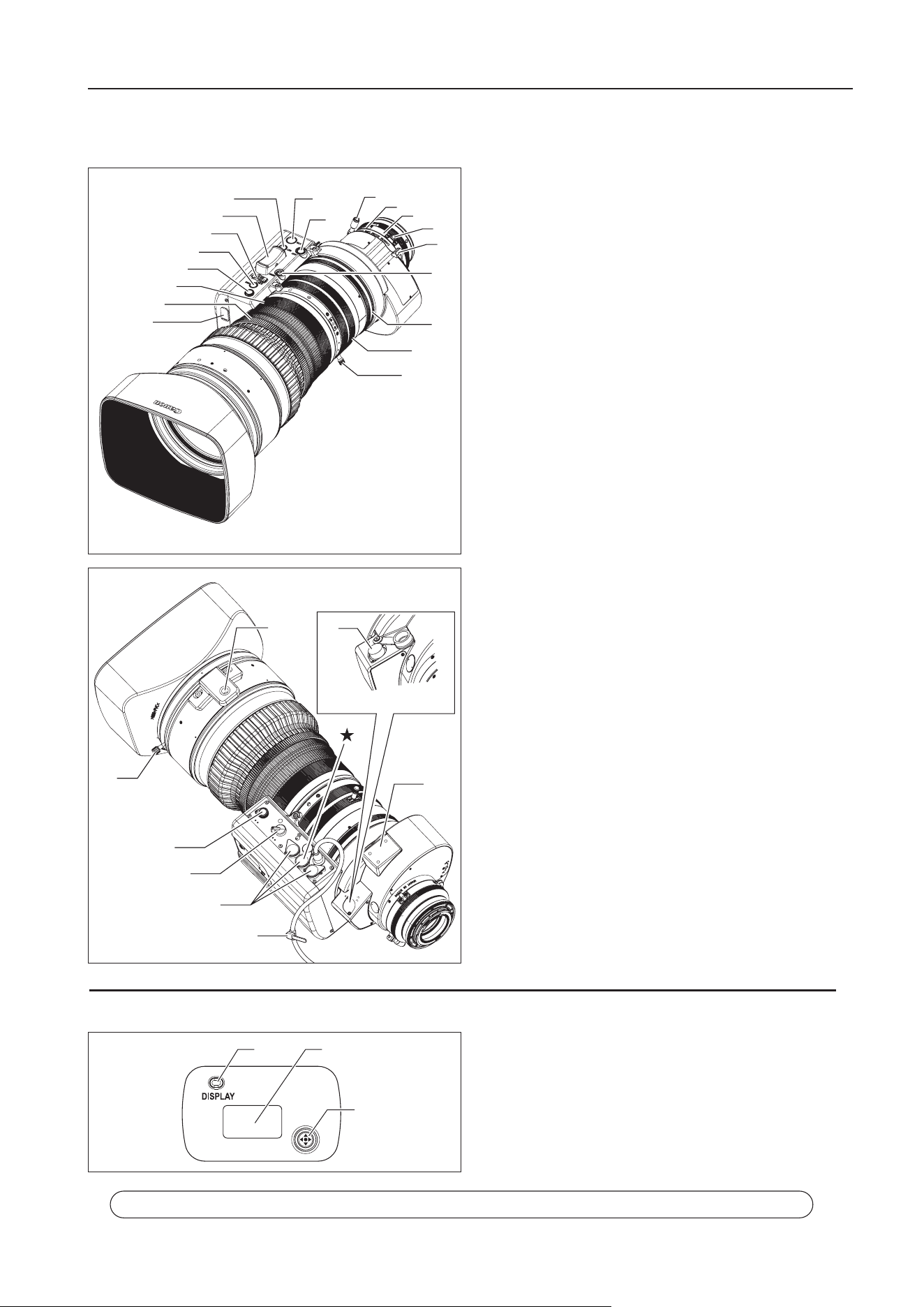
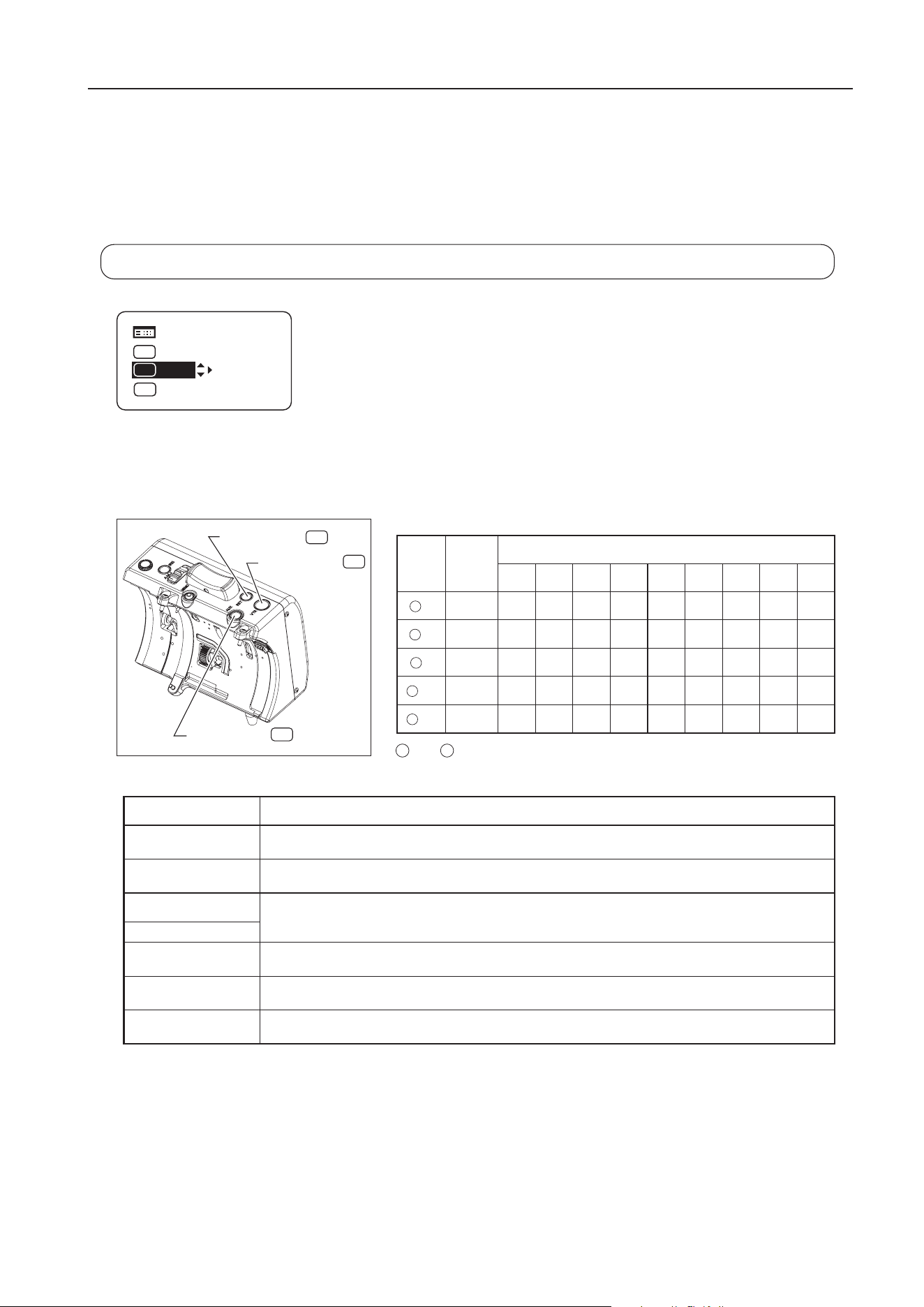
①
Display Switch
Used to turn the display ON/OFF.
②
Display
It turns o if left for 2 minutes without operation.
③
Control key
Used to move the cursor up/down/left/right. Press the
center to conrm.
1 NOMENCLATURE
Information Display (Digital Drive Unit)
1 NOMENCLATURE
For the operation of the digital drive unit, refer to
Operation Manual "Information displa
y"
.
①
②
③
④
⑤
⑥
⑦
⑧⑨
⑩
⑪
⑫
⑬
⑮
⑯
⑭
⑰
⑱
⑲
㉖
⑳
㉑
㉒
㉓
㉔
㉕
㉗
PL Mount Lens Only
①
②
③
E3
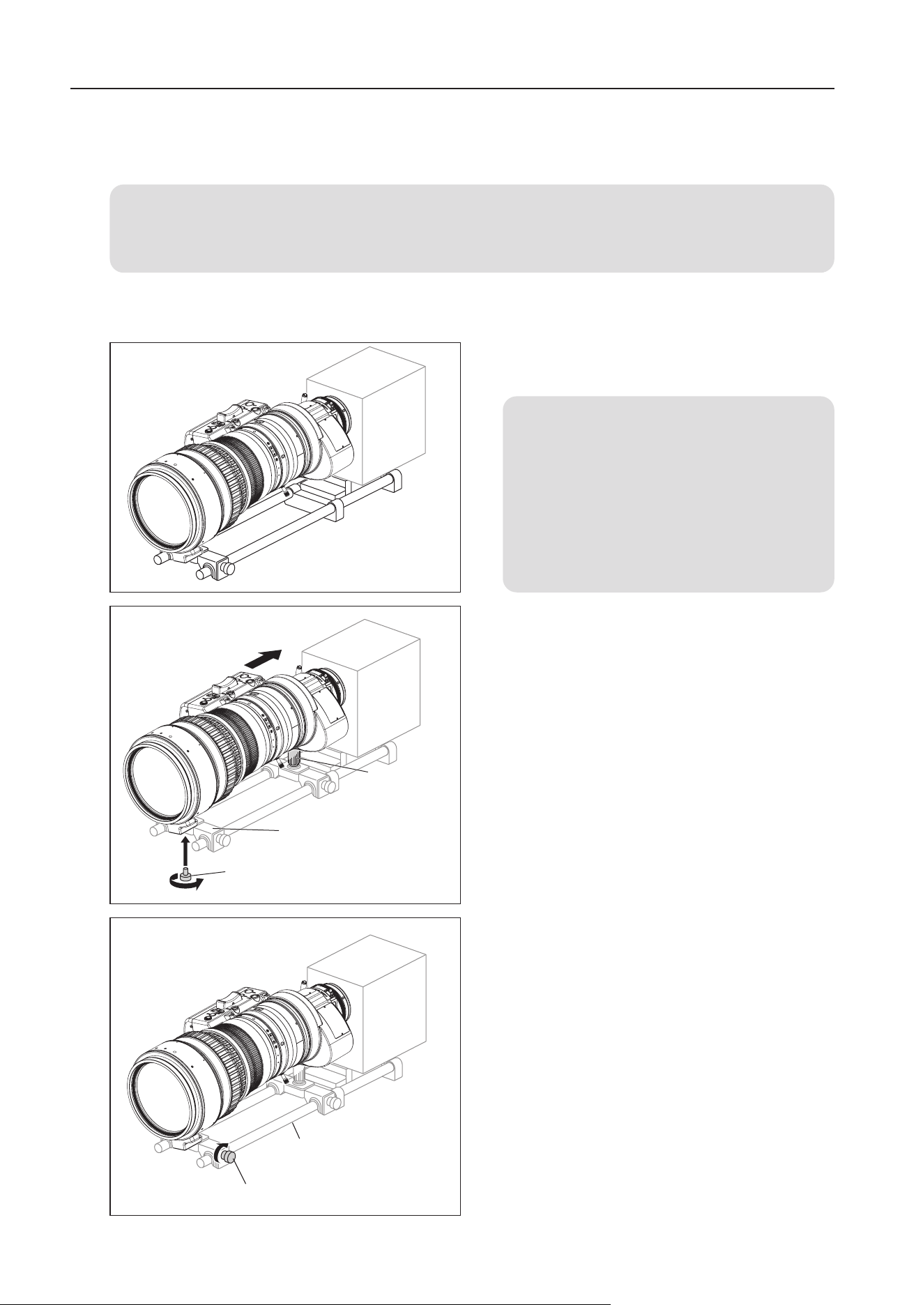
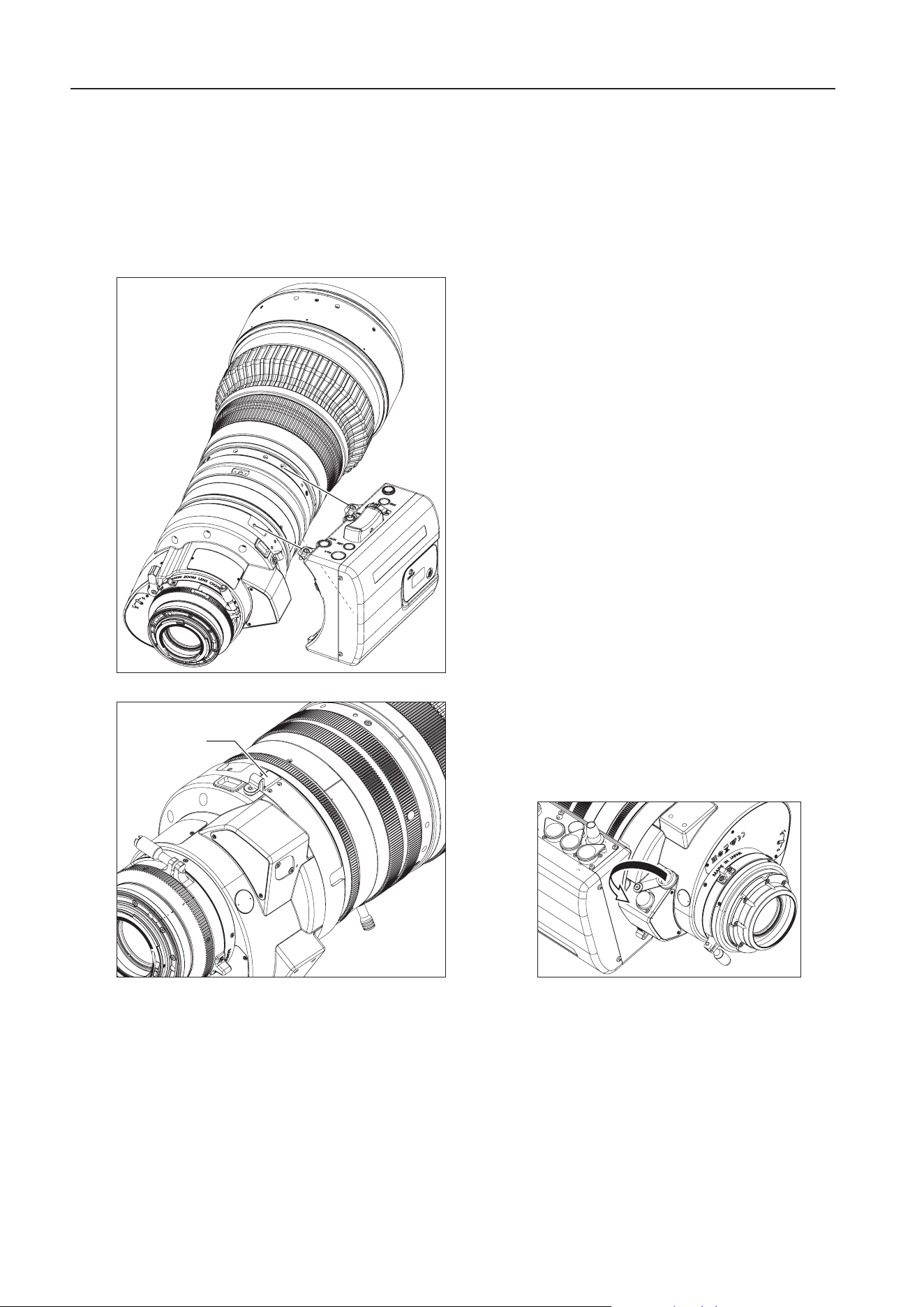
1
Attach the lens to the camera tightly so that both
mounting surfaces are in complete contact.
NOTE
1. The mounting method differs depending
on the lens mounts. Refer to the operation
manual for the respective camera for the
detailed information.
2. If the rod interferes with the lens body or
drive unit when mounting the lens, remove
the rod and then mount the lens.
2
Secure the lens holder on the lens support using the
screw supplied with the lens support.
3 Secure the attachment holder to a different lens
support from the lens support mentioned in step 2,
and fit the attachment holder into the attachment
holder contact plate ( ㉑ in figure on page 2) at the
rear of the lens.
4 Fix the lens support to the rods using lens support
xing screws.
2 HOW TO MOUNT
2-1. MOUNT THE LENS ON THE CAMERA
For PL mount, read the following instructions before mounting the lens.
1. The PL mount supports Cooke’s /i Technology, so make sure that the camera is set to “/i”.
2. Do not mount the lens if the camera is set to a mount communication mode other than “/i”. Doing so could
result in malfunction.
Before mounting the lens on the camera, make sure that the power of camera and the power of supply
equipment are turned o.
2 HOW TO MOUNT
Lens Support
Screw supplied with the
Lens Support
Attachment
Holder
Rods (
φ
19)
Lens Support Fixing Screws
E4
1 Fit the hood on the front of the lens barrel.
2 Align the index on the hood and lens barrel.
3 Tighten the hood lock knob.
2-3. TURN IT ON
Turn on the camera and power supply equipment on, and the power of the lens will be supplied.
2-2. MOUNT THE HOOD ON THE LENS
The lens cap is attached to the lens at the factory. Please remove the lens cap before mounting the hood.
2 HOW TO MOUNT
5 When the lens is mounted, connect the cable from
the drive unit to a power supply equipment such as
camera or external power supply.
Or if the camera can be powered from the PL mount,
connect the cable from the drive unit to the connector
below the lens mount.
* Connect the cable so that the connector of the cable
aligns with the connector of the lens.
* Bundle up the cable with the tie cable as needed.
NOTE
Rated voltage: 12 VDC
Normal operation range: 10 to 17 VDC
If a battery or adapter is used, the output voltage may be higher than the rated voltage depending on the manufacturers
and therefore the above voltages must be observed strictly. If a voltage outside the normal operation range is used, the
drive unit may be damaged. And the lens power input has the positive and negative polarities. Make sure to connect the
power cable to the correct polarity when connecting the batteries or the adaptors. Connecting the cable to the incorrect
polarity may cause the damage to the product.
Hood
Hood Lock Knob
Index
Lens
Barrel
E5
2 HOW TO MOUNT
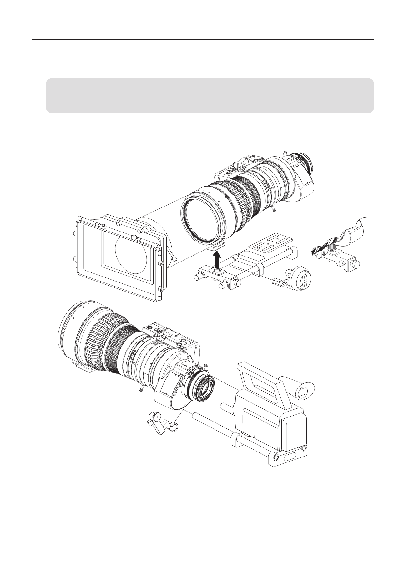
2-4. AVAILABLE ACCESSORIES
A variety of professional camera accessories are available using
φ
19 mm rod adaptors.
NOTE
Be sure to use the lens holder when mounting the lens on a camera. Be sure to avoid applying excessive force to
the lens mount when the lens is mounted on a lens support.
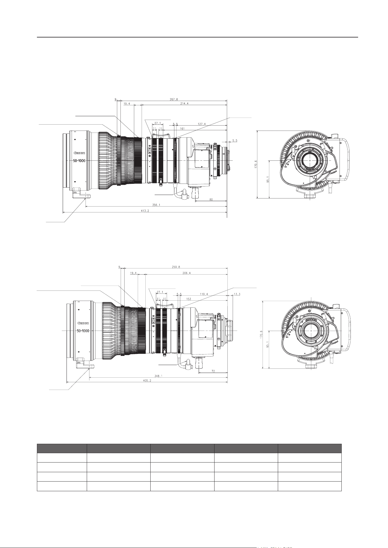
E6
2 HOW TO MOUNT
2-5. DIMENSIONS OF PARTS
(Unit: mm)
CN20x50 IAS H/E1 (EF mount)
Spur gear specications
Focus drive gear A Focus drive gear B Zoom drive gear Iris drive gear
Number of teeth
156 230 225 225
Module
0.8 0.5 0.5 0.5
P.C . D.
124.8 mm 115 mm 112.5 mm 112.5 mm
Angular rotation
180 degrees 180 degrees 100 degrees 52.5 degrees
Lens Holder
Focus Drive Gear A
Focus Drive Gear B
Iris Drive Gear
Zoom Drive Gear
(UNC3/8-16)
Tie Cable
Lens Holder
Focus Drive Gear A
Focus Drive Gear B
Iris Drive Gear
Zoom Drive Gear
(UNC3/8-16)
Tie Cable
CN20x50 IAS H/P1 (PL mount)
E7
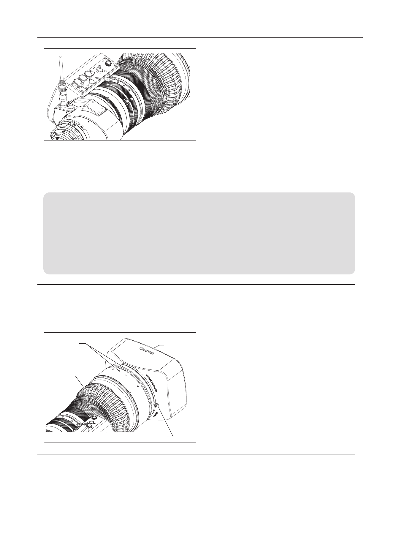
3 ADJUSTMENT
3-2. IRIS GAIN ADJUSTMENT
An iris gain adjusting trimmer is located on the front of the lens drive unit. The iris gain is set appropriately
at the factory. However, if you wish to change the iris gain, adjust the trimmer using a small screwdriver.
3 ADJUSTMENT
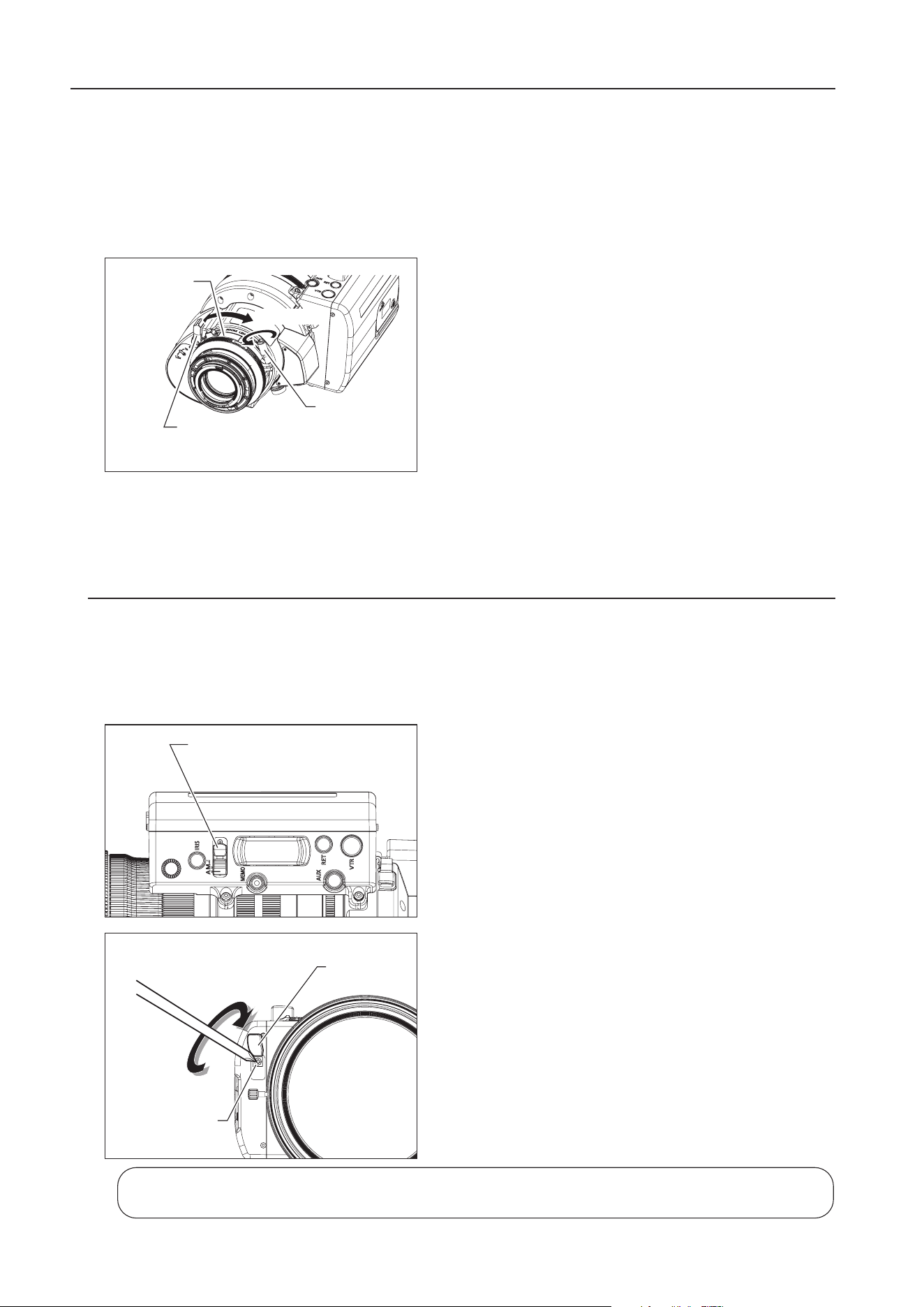
3-1. BACK FOCUS ADJUSTMENT OF THE LENS
If the relation between the image plane of the lens and the image plane of the camera is incorrect, the object
goes out of focus at the time of zooming operation. Follow the procedure below to adjust the back focus of
the lens.
1
Select an object at an appropriate distance (approx. 5 to
7m). Use any object with sharp contrast to facilitate the
adjustment work.
2 Set the extender switching lever to 1x.
3 Set the iris fully open.
4 Set the lens to the telephoto angle by turning the zoom
ring.
5 Bring the object into focus by turning the focus ring.
6 Set the lens to the widest angle by turning the zoom ring.
7 Loosen the ange back lock screw, and turn the ange
back adjusting ring to bring the object into focus.
8 Repeat steps 4 to 7 a few times until the object is brought
into focus at both the widest angle and telephoto ends.
9 Tighten the ange back lock screw.
Flange Back
Lock Screw
Loosening
Flange Back
A
djusting Ring
Extender
Switching
Lever
1 Set the iris operation mode change-over switch to the "A"
(Auto) position.
2 Pull up the rubber cap on the iris gain adjusting trimmer.
3
Turn the iris gain adjusting trimmer, using a small screwdriver.
As you look at the lens iris ring, set it to the position of
maximum gain at which no focus hunting occurs.
4 Put back the rubber cap after adjustment completes.
Iris Operation Mode
Change-over Switch
Clockwise
(to increase gain)
Rubber Cap
Iris Gain Adjusting
Trimmer
The adjustment and the setting can also be made on the information display. Refer to
Operation Manual
"Information displa
y"
.
E8
4 MODE SETTING
4 MODE SETTING
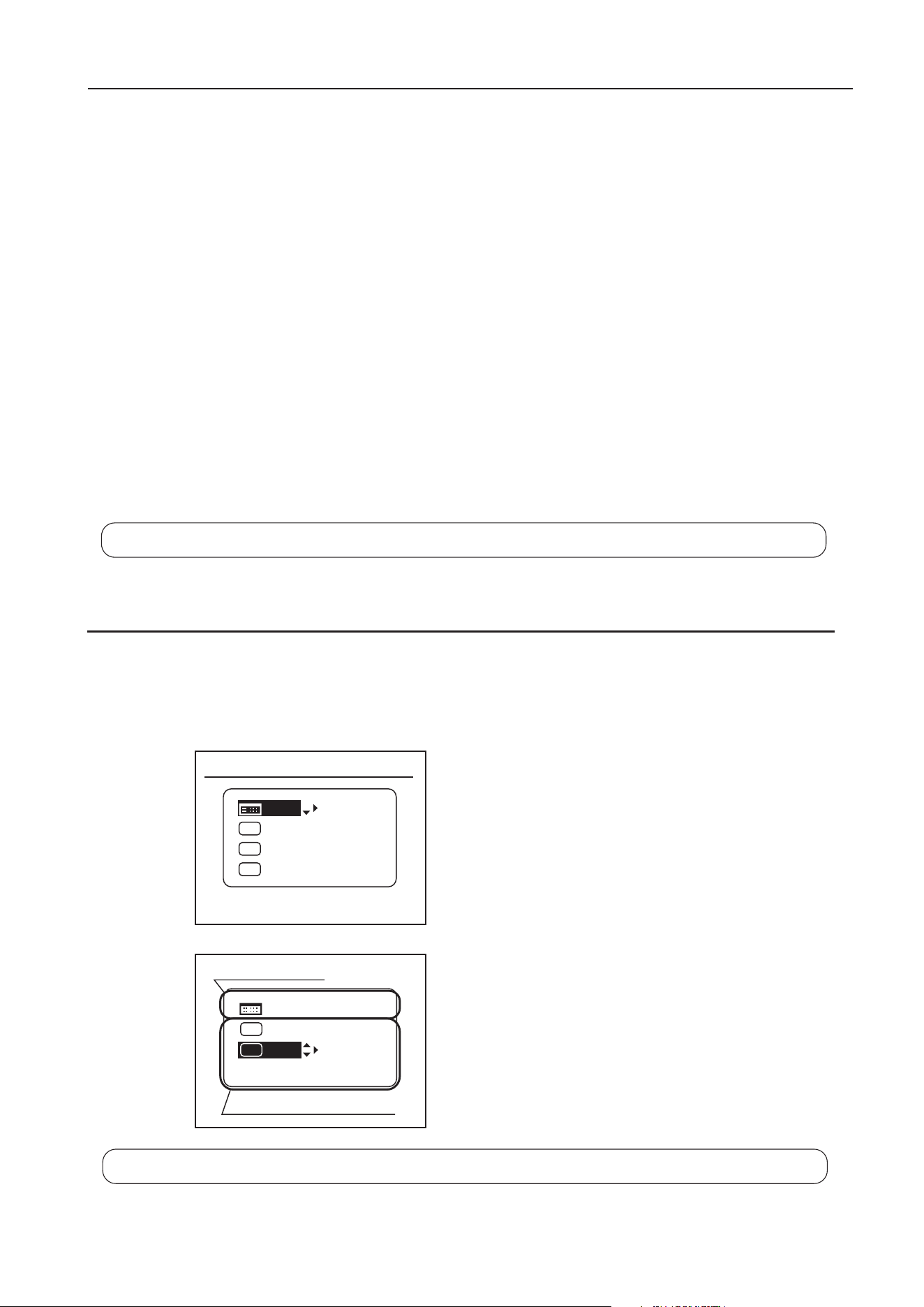
4-2. SETTINGS IN BASIC MODE
The following nine settings can be made on the Top screen in Basic Mode.
1. Go to MENU screen
2. Auto iris gain settings
3. AUX switch assignment
4. Automatic adjustment of mechanical end
5. AUX1 switch assignment
6. Zoom tracking ON/OFF
7. AUX2 switch assignment
8. Iris torque settings
9. Zoom curve mode settings
[Trk]
OFF
Shtl
A 1
A 2
MENU
IG: 50
A
Fr1P
Fr1P
[I-Tq]H
[Adj]
Initial Top screen in Basic Mode
MENU
[ Z.M. ]
A 2
A 1
IG: 50
Fr1P
[Trk]
OFF
[I-Tq]H
Items displayed by scrolling
Items not scrolled
Shtl
For details on how to set them, refer to
Operation Manual "Information displa
y".
4-1. OPERATION MODES
This product has an information display on which various settings can be customized. There are three
operation modes below as a setting menu. One of the operation modes can be selected according to usage
and preference.
1. Basic mode : Items that can be set and viewed are limited in this mode, and are recommended to
users who do not require complex settings. This product is factory-set to basic mode.
2. Full mode : All items can be set and viewed in this mode.
3. Analog mode : It is the mode chosen when not using a digital function at all
• Switches labeled VTR, RET, IRIS A/M, and IRIS INST control the respective functions. The rocker
switch serves as a regular zoom switch.
• AUX and MEMO switches are disabled.
• To set auto iris gain adjustment, use either display or trimmer operations.
• Shuttle shot, framing preset, speed preset, and zoom tracking are not available.
This manual describes only the items that can be set on the TOP screen in each mode.
For details on how to set them, refer to
Operation Manual "Information displa
y".
E9
4 MODE SETTING
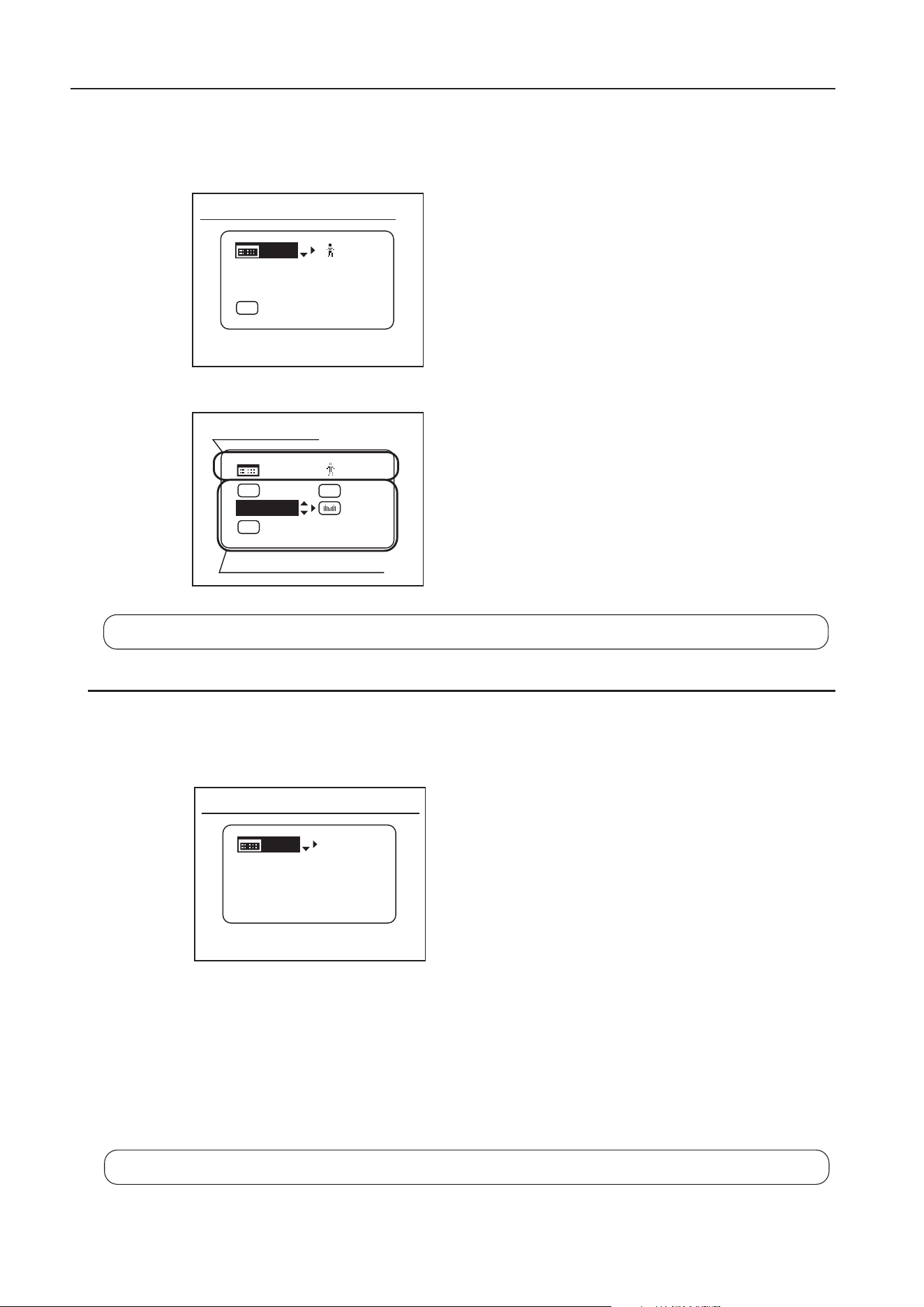
4-3. SETTINGS IN FULL MODE
The following 15 settings can be made on the Top screen in Full Mode.
1. Go to MENU screen
2. Switch users
3. Switch to Basic Mode
4. Automatic adjustment of mechanical end
5. Iris gain settings
6. Zoom tracking ON/OFF
7. AUX switch assignment
8. Iris torque settings
9. AUX1 switch assignment
10. VTR switch assignment
11. AUX2 switch assignment
12. RET switch assignment
13. Zoom curve mode settings
14. Seasaw switch assignment
15. Iris A/M switch setting
[ I-Gain ][Trk]
OFF
[]
MENU
1
A
Fr1P
[ Basic ]
[Adj]
[Trk]
OFF
[I-Tq]H
Initial Top screen in Full Mode
Items displayed by scrolling
Items not scrolled
[]
MENU
1
Norm
AM
Zoom
[ Z.M. ]
RET
R
A 2
Fr1P
MENU
IG: 50
[ Basic ]
Initial Top screen in Analog Mode
4-4. SETTINGS IN ANALOG MODE
The following three settings can be made on the Top screen in Analog Mode.
1. Go to MENU screen
2. Auto iris gain settings
3. Switch to Basic Mode
For details on how to set them, refer to
Operation Manual "Information displa
y".
For details on how to set them, refer to
Operation Manual "Information displa
y".
E10
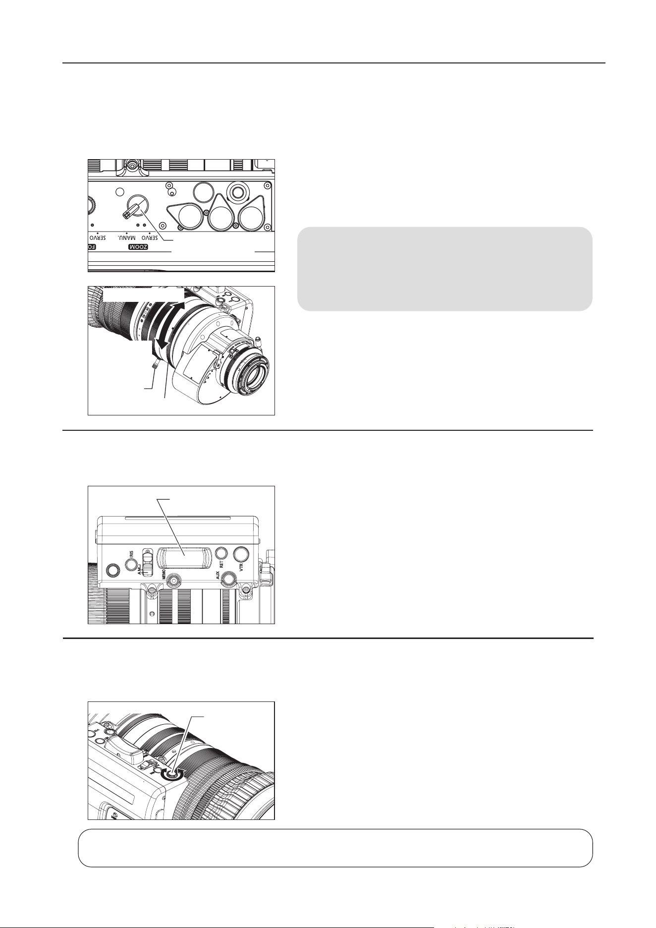
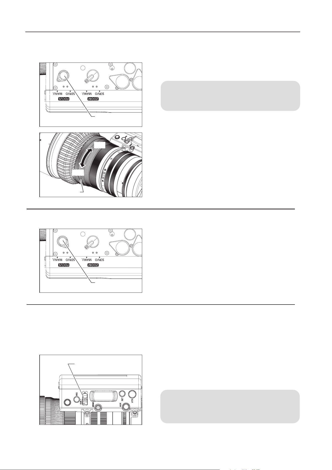
5 OPERATION
1 Set the zoom operation change-over knob at the bottom of
the lens drive unit to MANU. position.
2 Turn the zoom ring (or zoom lever) to perform zoom operation.
NOTE
The zoom operation change-over knob must be set to the
MANU. position before performing manual zoom operations.
The lens may be damaged if manual zoom operations are
forcibly performed with the knob at the SERVO position.
5-1-2. Servo Zoom Operation
Zoom operation can be performed by driving the built-in motor in the lens.
5 OPERATION
5-1. ZOOM OPERATION
5-1-1. Manual Zoom Operation
1 Set the zoom operation change-over knob to SERVO position.
2 Press the zoom rocker seesaw to perform zoom operation.
Zoom speed changes by the depth of the switch being pressed.
The deeper the switch is pressed the faster the zoom speed
becomes.
5-1-3. Maximum Zoom Speed Adjustment
The maximum speed of zoom when the zoom rocker seesaw is pressed can be adjusted with the max.
zoom speed adjusting volume.
Zoom Operation
Change-over Knob
Toward
Telephoto end
Toward Widest end
Zoom Lever
Zoom Ring
Zoom Rocker Seesaw
Max. Zoom
Speed Adjusting
Volume
The adjustment and the setting can also be made on the information display. Refer to
Operation Manual
"Information displa
y"
.
E11
5 OPERATION
NOTE
1) If the zoom track position is to be set again, the zoom position cannot move beyond the end point setting
toward the mechanical end by performing servo zoom operations. To move the zoom, set the zoom track
function to OFF and take one of the steps below.
・ Proceed with the zooming operation at the setting established by operating the zoom rocker
seesaw.
・Perform the zooming operation manually.
2) Although up to two zoom track positions (telephoto end and widest end) can be set, two positions cannot
be set that are on the same side of the center position of the zoom range of this lens.
(In this case, the latest setting is stored as the zoom track position of this side.)
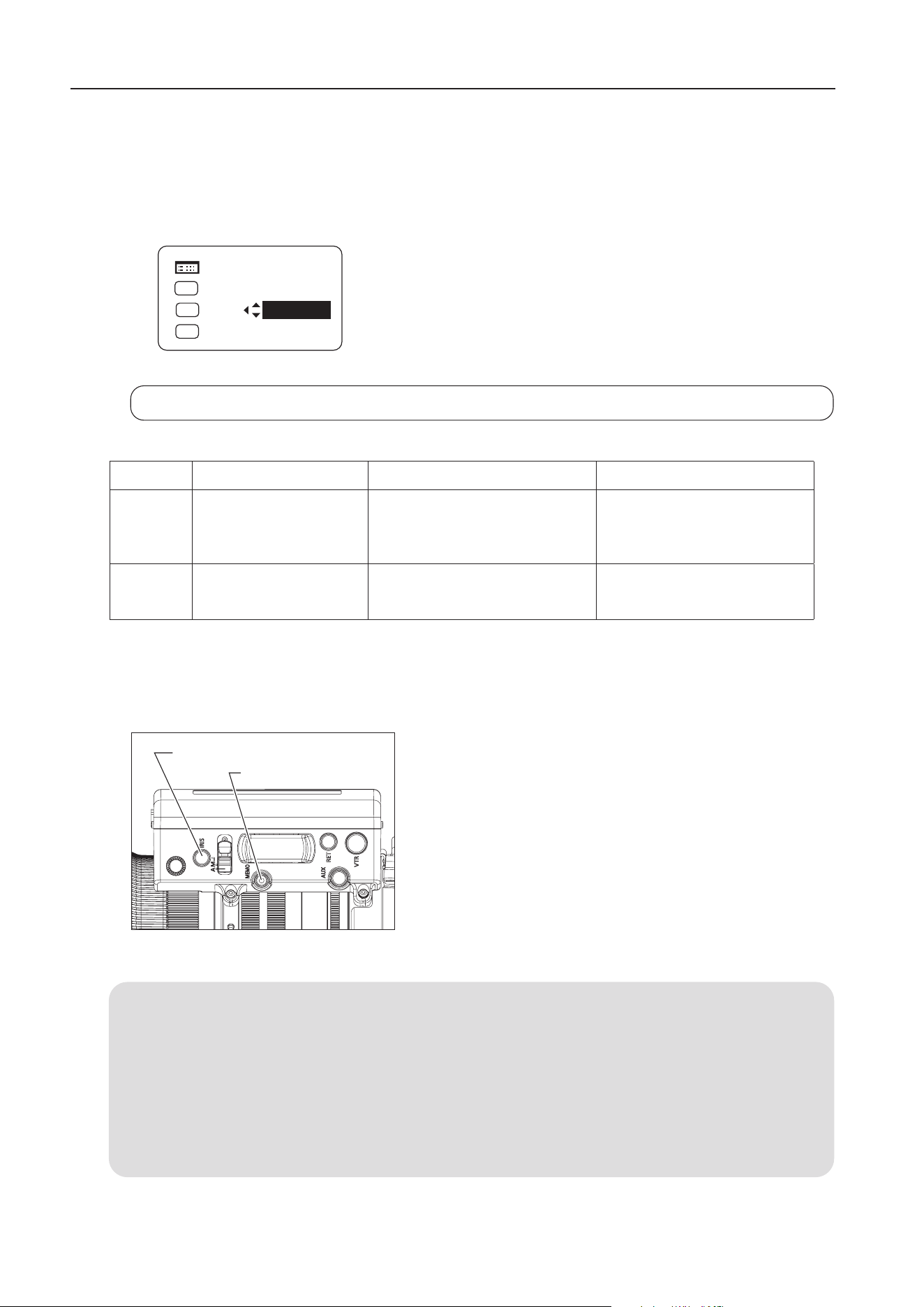
5-1-4. Zoom Track Function
(only for servo zoom)
The zoom control range (zoom track) position can be set as desired to set the virtual zoom limit in the telephoto end
and the widest end. To use the zoom track function, the function should be enabled in advance.
A: Setting ON or OFF on the information display (In case of basic mode)
1 Press the DISPLAY switch to turn on the display.
2 Select [Trk] using the control key, and then press the Set key. [Trk] and
the last setting now blink on the display. (see left gure)
3 Press the left or right key to select ON or OFF.
4 Press the Set key. This completes the setting.
For details on how to set each setting item, refer to
Operation Manual "Information displa
y"
.
B: Setting ON or OFF by operating the switches
Selection method Operation How to ascertain the selection
To set the
function to
ON
Hold down the MEMO
switch and Instant auto-
iris switch simultaneously
for at least 3 seconds.
The zoom control range is xed to
the zoom range set last. (If there is
no previous setting, it is set to the
mechanical end.)
Automatic zooming from current
zoom position to the closer of the
two set positions.
To set the
function to
OFF
The zoom range is set to
the mechanical end.
The zoom range is set to the
mechanical end.
Automatic zooming from current
zoom position to the closer of
the two mechanical ends.
[Trk]
OFF
Shtl
A 1
A 2
IG: 50
A
Fr1P
Fr1P
[I-Tq]H
[Adj]
MENU
Setting the Zoom Track Positions
Set the zoom track function to ON before setting the zoom track position.
1 Zoom to the zoom track position that you want to set.
2 Keeping this zoom position, press the Instant auto-iris switch
while holding down the MEMO switch. If the zoom position is
at the telephoto end, the position is stored as the zoom track
position for the telephoto limit. If position is at the widest end, it
is stored as the widest limit.
3 Repeat step 1 and 2 to set both telephoto and widest limits. It
is possible to set only one end. To change the setting, perform
step 1 to 3. (The position set last overwrites the setting in the
memory.)
Instant Auto-Iris Switch
MEMO Switch
E12
Before using shuttle-shot function, the shuttle function must be assigned to the VTR, RET, or AUX switch
of the drive unit, or the AUX1 or AUX2 switch on the zoom demand. This manual describes the Shtl
function assigned to the VTR switch. For details, refer to "5-6 SWITCH OPERATIONS".
5-1-5. Shuttle-Shot Function
This function allows you to switch between the current zoom position and the preset zoom position at the
maximum speed.
5-1-6. Speed Preset
This function allows you to call the preset zoom speed any time you zoom. Assign the Sped function to the
VTR, RET, or AUX switch of the drive unit, or AUX1 or AUX2 switch on the zoom demand. This manual
describes the Sped function assigned to the VTR switch.
1. Storing the zoom speed and direction
Operate the zoom rocker seesaw to determine the zoom
speed and direction (toward telephoto angle or widest angle)
which you want to store, and press the MEMO switch while
holding this position.
NOTE
The stored zoom speed is applied to the Framing Preset.
Current zoom position Shuttle memory position Previous zoom position
The Shtl
switch is
held down.
The Shtl
switch is
released.
Max
speed
Max
speed
Setting the shuttle memory position
Zoom to the position that you want to store. Keeping this
position, press the Shtl switch while holding down the
MEMO switch.
NOTE
1. The position you stored here is different from the
one you set in Framing Preset mentioned later. The
stored position set here is retained even after the
power is turned o.
2. The operation with the Shtl switch is given the priority
over that with the zoom rocker seesaw. The operation
with the zoom rocker seesaw is disabled while the
Shtl switch is pressed.
5 OPERATION
Sped
Switch
Zoom Rocker Seesaw
MEMO
Switch
Shtl
Switch
Zoom Rocker Seesaw
MEMO Switch

E13
5 OPERATION
2. How to operate the speed preset function
When the
Sped
switch is pressed, the zoom starts to move at the preset speed and to the determined
direction (toward telephoto angle or widest angle) stored in section 1 and stops at the zoom end.
3. How to cancel movement in Speed Preset
Movement in Speed Preset can be canceled by any of the following operations.
1) Press the Sped switch again. → Zooming stops.
2) Perform zoom operation with the zoom rocker seasaw / Shtl / Fr1P / Fr2P / Fr1F or Fr2F switch.
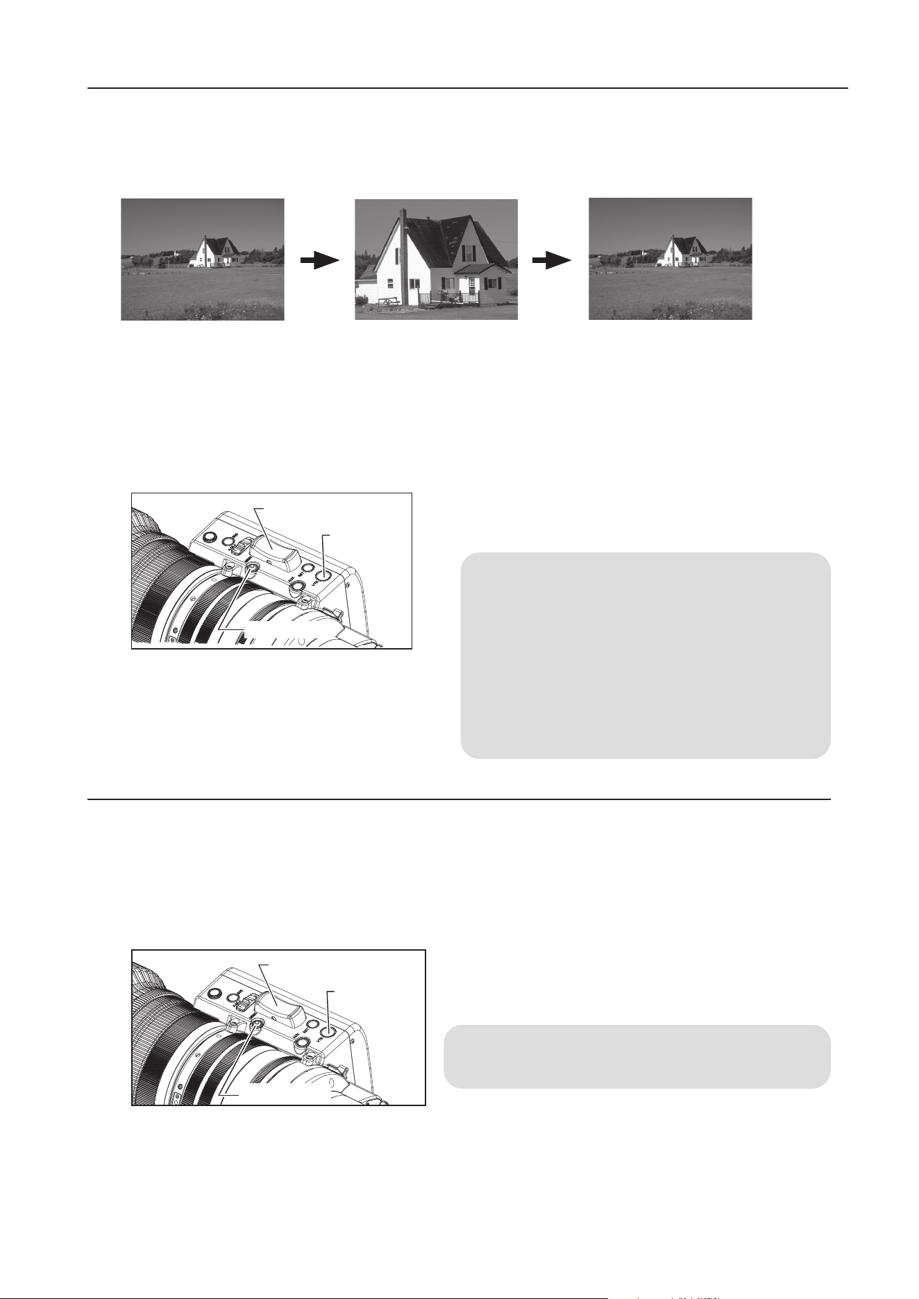
5-1-7. Framing Preset
There are three framing preset types based on how the settings are combined.
[Zoom]:
This enables a predetermined picture angle and movement speed (zoom speed) to be reproduced easily.
[Focus]:
This enables a predetermined focus to be reproduced easily.
[Z+F] :
This enables the movement speed (focus speed, zoom speed) to a predetermined focus and picture
angle to be reproduced easily.
NOTE
Up to two framing presets, Frame1 and Frame2, can be stored in the memory. Only Frame1 is described in
the description given on the following pages. Frame1 is indicated as
Fr1P
.
Control content
Movement speed setting
Framing preset
control
Setting combinations
Zoom
Z+F
Focus
Fr1P, Fr2P
(speed settable)
The zoom moves at the preset speed.
Zoom operation
control
Focus operation
control
Zoom + focus
operation control
The zoom moves at the maximum speed.
The focus moves at the maximum speed.
The focus moves at the maximum speed.
The zoom and focus move at the
maximum speed.
The zoom and focus move at the preset speeds.
(maximum speed)
*1
*1: The zoom and focus are controlled in such a way that they start and stop simultaneously.
Fr1F, Fr2F
How to set the zoom speed to the framing memory position
Movement speed to the framing position is selected by assigning the Fr1P or Fr1F switch.
•
Fr1P---------- For the preset speed setting (preset speed) (Assigned to the AUX switch at the factory.)
•
Fr1F----------For the maximum speed setting (fast speed)
For details on how to assign the switches, refer to 5-6. SWITCH OPERATIONS.
Frame1:
ZSpeed:
800
Frame2:
Zoom
Preset
Zoom
The framing preset setting is changed on the Preset screen on the
information display. The Frame1 setting is changed to Zoom, Focus, or Z+F.

E14
2. Moving to the framing memory position
Once the Fr1P switch is pressed, the zoom starts to move toward the framing memory position at the preset speed
and stops at the framing memory position.
3. Canceling the movement to the framing memory position or switching to other zoom operation
Movement to the framing memory position can be canceled by any of the following operations.
[Zoom Framing Preset]
• Press the Fr1P switch again.
• Perform zoom operation with the zoom rocker
seesaw.
• Perform zoom operation with the
Shtl switch.
[Zoom, Focus Framing Preset]
• Operate a connected focus demand. Movement to
the memory position stops, and movement to the
operating position of the focus demand takes place.
1. Setting the framing memory position
Zoom (and focus) to the position that you want to store, while
holding this zoom (and focus) position, and then press the
Fr1P
switch while holding down the MEMO switch.
NOTE
This framing memory position is dierent from the shuttle
memory position.The stored zoom position is retained
even after the power is turned o.
5 OPERATION
Zoom Rocker Seesaw
Shtl Switch
Fr1P Switch
MEMO Switch
Framing Preset [Zoom]/[Focus]/[Z+F] Setting
NOTE
The following gure is shown as an example. Actual state of the switch may look dierent if the function
is allocated to the dierent switch.
Fr1P function--------Assigned to the AUX switch by factory default.
E15
5 OPERATION
1 When the manual focus operation is performed, set the
focus operation change-over knob to MANU. position.
NOTE
The lens may be damaged if the focus ring is turned
forcibly with the knob at the SERVO position.
2 Turn the focus ring to bring the near or far object into
focus.
5-2. FOCUS OPERATION
5-2-1. Manual Focus Operation
Slide the iris operation mode change-over switch to the "A"
position.
The iris operation is performed automatically by the instruction
from the camera, to keep the video signal level constant.
NOTE
The automatic iris operation may not be performed depending
on the types of cameras.
5-3. IRIS OPERATION
The iris operation mode can be switched between auto and manual with the iris operation mode change-over
switch.
5-3-1. Automatic Iris Operation
5-2-2. Servo Focus Operation
1 When the servo focus operation is performed, set the
focus operation change-over knob to SERVO position.
2 Mount the accessory such as focus demand. For the details,
refer to the operation manual of accessories.
Focus Operation
Change-over Knob
Focus Ring
Far
Near
Iris Operation Mode
Change-over Switch
Focus Operation
Change-over Knob
E16
Slide the iris operation mode change-over switch to the "M"
position. The iris operation is performed by turning the iris ring on
the lens body.
NOTE
The iris operation mode change-over switch must be set to
the "M" position before performing manual iris operations.
The lens may be damaged if manual iris operations are
forcibly performed with the knob at the "A" position.
The adjustment and the setting can also be made on the information display. Refer to
Operation
Manual "Information displa
y"
.
5-3-2. Manual Iris Operation
When the instant auto-iris switch is pressed during manual iris
operation, the iris changes to automatic operation mode while the
switch is held down.
NOTE
The automatic iris operation may not be performed
depending on the types of cameras.
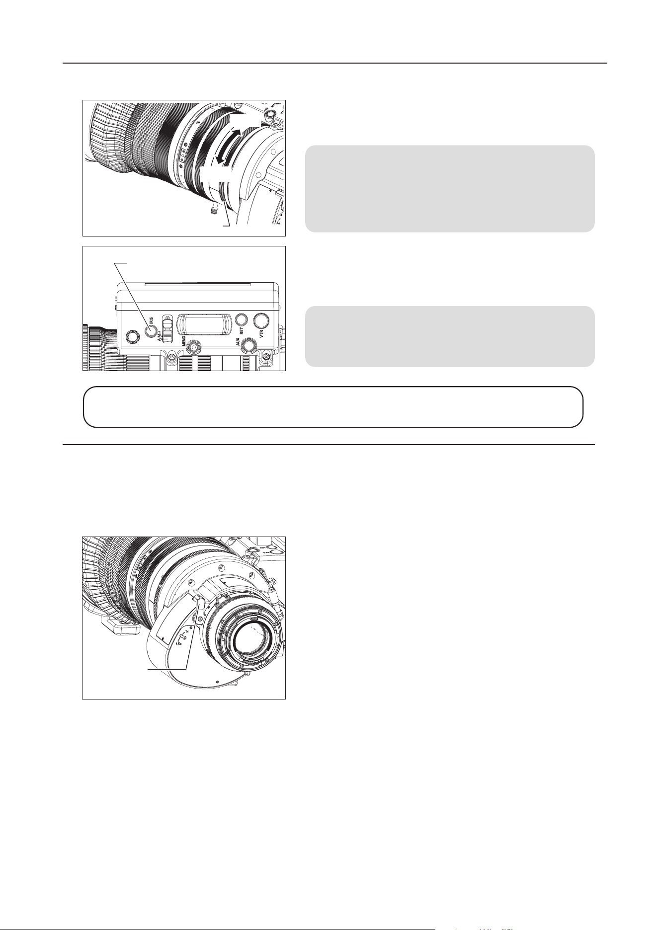
5 OPERATION
The extender is operated by moving the extender switching
lever at the rear of the lens. When the extender switching lever
is on the 1.5x index side, the state of the lens is equivalent to
having a 1.5x extender mounted.
Note that moving the extender switching lever to the 1x index
side removes the 1.5x extender and returns to lens to the
master lens state.
5-4. EXTENDER OPERATION
The lens is equipped with a built-in 1.5x extender. The focal length of the lens can be extended to 1.5 times by
operating the extender. Note, however, that using the extender lowers the T number by an amount equivalent to
the change in focal length, depending on the iris compensation setting.
Extender
Switching
Lever
Instant Auto-Iris Switch
Close
Open
Iris Ring

E17
To operate the macro, press the macro button to unlock the
macro ring. While holding it down, turn the macro ring at the
rear of the lens clockwise as viewed from the camera side to
allow macro shooting.
1 Set the lens to the widest angle by manual or servo zoom
operation.
2 Bring the object into focus by turning the macro ring.
NOTE
Macro operation is also possible at any zoom position other
than the widest angle, but the object distance increases.
5-5. MACRO OPERATION
In macro shooting, the object distance becomes shorter than the normal minimum object distance (M.O.D.).
The minimum object distance by macro operation for this lens is 1.54 m from tip of the lens at the widest
angle.
Macro Ring
Macro Button
5 OPERATION
In macro shooting, when zooming to change the focal length, the focal point varies.
The multi-point focus shooting technique uses this characteristic. The focal point is shifted by the zoom
operation. Follow the steps bellow :
1 Zoom in to a far object, and bring it into focus by normal focus operation.
2 Zoom out to a near object and bring into focus by macro operation.
3 Zoom in to the far object again while not touching the macro button set by above step 2, and bring into
focus again by normal focus operation.
Multi-point Focus Shooting
E18
5-6. SWITCH OPERATIONS
Functions can be assigned to the ve switches: the VTR, RET, AUX switches of the drive unit, or AUX1 and
AUX2 switches on the zoom demand on the information display. VTR, RET, Fr1P, Shtl, and Fr1P functions
are assigned respectively by default.
The following steps explain how to assign the functions to the switches in basic mode.
For further details, refer to
Operation Manual "Information displa
y"
.
1 Press the DISPLAY switch to turn on the display.
2 After using the control key to select the name of the switch key to which the
function is to be allocated, press the Set key. The name of the switch and
the default or last setting now blink on the display.
3 Press the left or right key until the function to be changed appears on the
display.
4 Press the Set key. This completes the setting.
Switch
Default
value
Functions
Fr1P Fr1F Fr2P Fr2F Sped Shtl NON VTR RET
1
V VTR
● ● ● ● ● ● ● ●
2
R RET
● ● ● ● ● ● ● ●
3
A Fr1P
● ● ● ● ● ● ● ● ●
4
A1 Shtl
● ● ● ● ● ● ● ● ●
5
A2 Fr1P
● ● ● ● ● ● ● ● ●
4
and
5
are AUX1 and AUX2 switches on the zoom demand.
Switch name Description
VTR Starts/stops VTR operation.
RET Hold down to view the main-line video on the view nder.
Fr1P, Fr2P
Press to move to the stored zoom/focus position.
One position can be stored/called per each switch for Fr1P, Fr1F and Fr2P, Fr2F.
Fr1F, Fr2F
Sped
Press to move in the stored zoom direction (toward telephoto or widest end) at the stored
zoom speed.
Shtl
Press to move to the stored zoom position at the maximum speed. Release to return to
the previous zoom position at the maximum speed.
NON No function
[Trk]
OFF
Shtl
Fr1P
A 1
A2
MENU
IG:50
Fr1P
A
[ I-Tq]
H
[ Adj]
5 OPERATION
③ AUX Switch
A
V
R
① VTR Switch
② RET Switch
E19
6 HOW TO ATTACH AND DETACH THE DRIVE UNIT
6 HOW TO ATTACH AND DETACH THE DRIVE UNIT
This product is structured so that the drive unit can be separated from the lens body. If it is used as a manual
lens, detach the drive unit while referring to Section 6-1. If the drive unit is mounted again, mount it while
referring to Section 6-2.
6-1. HOW TO DETACH THE DRIVE UNIT
1 Turn the camera and the lens power o.
2 Disconnect the 12-pin cable.
3 Detach the lens body from the camera.
4 Loosen the three drive unit fixing screws and
detach the drive unit from the lens body.
5 Cap the contact on the lens body.
If power is supplied from the camera when the PL
mount lens is used, remove the 12-pin cable and
then cap the connector.
Cap

E20
NOTE
• Take care not to damage the drive unit cover when removing the drive unit xing screws.
• Use a Phillips screwdriver with a shaft diameter of 4 mm or less to remove the drive unit xing screws.
• Never insert the removed screws into the screw holes in which the drive unit was xed.
• When the lens is tilted, the zoom ring may turn and the zoom position may change. To retain the zoom
position when the lens is tilted, mount a cinema operation accessory with adjustable torque and with a pitch
of 0.5.
6 HOW TO ATTACH AND DETACH THE DRIVE UNIT
6 Place the detached drive unit in the supplied
storage bag.
E21
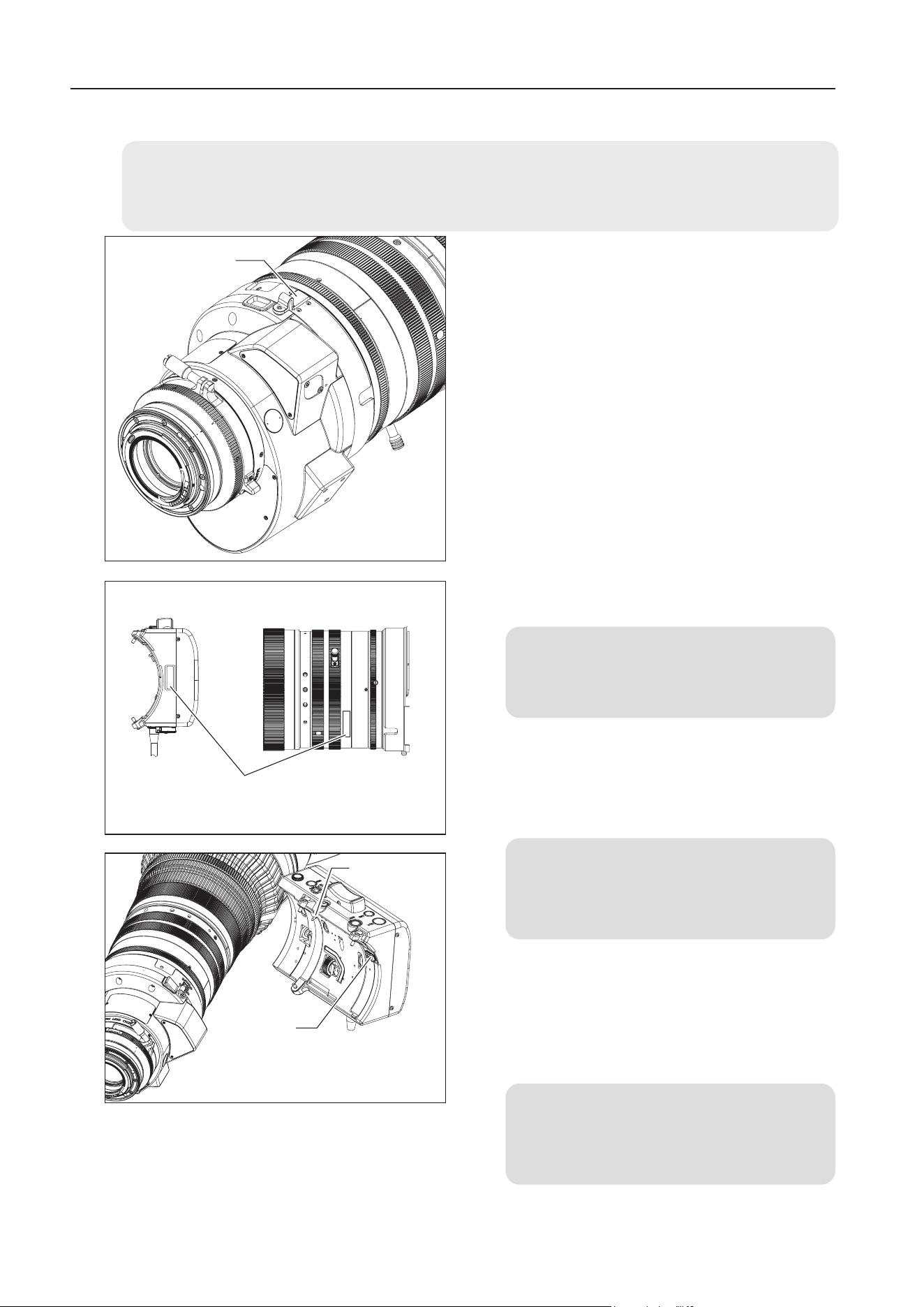
6-2. HOW TO ATTACH THE DRIVE UNIT
1 Detach the cap from the contact on the lens body,
x the cap on the projection on the main body.
2 Check that the serial numbers of the lens body
and the drive unit match.
NOTE
If the serial numbers do not match, malfunction
may occur.
3 Check that there are no foreign matters in the
three drive unit fixing screw holes in the lens
body.
NOTE
If the drive unit is xed when there is a foreign
material in a screw hole, the lens body may be
damaged.
4 Before attaching the drive unit, check the
positions of the positioning pin and the connector.
Then align the xing screws of the drive unit with
the drive unit mounting screw holes in the lens
body and attach the drive unit.
NOTE
Use the dedicated drive unit fixing screws that
were equipped with the drive unit and do not use
unspecied screws.
6 HOW TO ATTACH AND DETACH THE DRIVE UNIT
Cap
xxxxxxxx
xxxxxxxx
Serial No.
Connector
Positioning Pin
NOTE
If a drive unit xing screw is damaged or lost, use a spare one.
If all spare screws are used and additional ones are required, contact Canon Inc. or Canon distributers & sales
representatives.

E22
5 Set the zoom/focus operation change-over knobs of the
drive unit to MANU. side, set the iris operation mode
change-over switch to "M" side, and then turn the focus,
zoom and iris ring manually and check gear engagement.
6 Verify that the gear of the drive unit is engaged with the
gear of the lens and tighten the three xing screws to the
specied torque to x the drive unit.
* Tightening torque: 63 - 80 N・cm (6.4 - 8.2 kg•cm)
7 Mount the lens on the camera, connect the 12-pin cable,
switch the power on and adjust the mechanical end
automatically on the display.
* For details on how to adjust the mechanical end
automatically, refer to "6-3 AUTOMATIC ADJUSTMENT OF
THE MECHANICAL END" on the next page.
NOTE
If an error message appears on the display when
the power is turned on, contact Canon Inc. or Canon
distributers & sales representatives.
6 HOW TO ATTACH AND DETACH THE DRIVE UNIT
E23
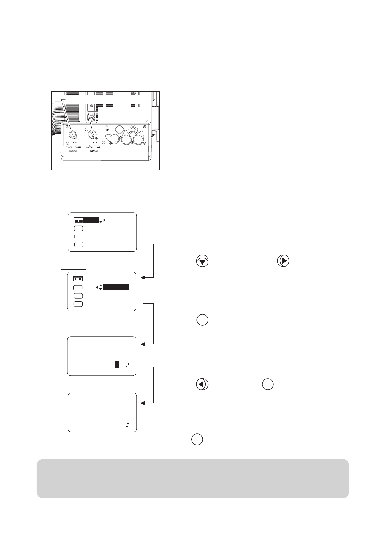
6 HOW TO ATTACH AND DETACH THE DRIVE UNIT
6-3. AUTOMATIC ADJUSTMENT OF THE MECHANICAL END
Set the zoom/focus operation change-over knob on the bottom
of the drive unit to SERVO position before starting the automatic
adjustment of the mechanical end.
Perform the following operation on the display and perform
the automatic adjustment of the mechanical end. Do not touch
operation rings, such as focus drive gear and zoom drive gear
during the automatic adjustment.
1 Press the key and then press the key.
2 Press the key.
Adjustment begins.
The screen changes to the Mechanical end adjustment screen
.
3 Press the key and press the key.
Initial Top screen
Set
Set
Set
Your selection is now highlighted.
The screen flashes during adjustment.
The adjustment is completed.
Press key after adjustment to return to Screen A.
Screen A
MENU
[Adj]
[Trk]
OFF
Shtl
A 1
A 2
MENU
IG: 50
A
Fr1P
Fr1P
[I-Tq]H
[Adj]
[Trk]
OFF
Shtl
A 1
A 2
IG: 50
A
Fr1P
Fr1P
[I-Tq]H
Lens
AutoAdjust
OK?
y/n
Auto-Adjustment:
Succeeded
Lens Interface:
Connected
Automatically adjust the mechanical end of the zoom, focus and iris of the lens body and drive unit.
Perform this adjustment if the drive unit is detached and reattached on the lens body again.
Zoom Operation
Change-over Knob
Focus Operation Change-over Knob
NOTE
If "Auto-Adjustment: Error/Lens Interface: Non-Connected" appears when the mechanical end adjustment is
completed, contact Canon Inc. or Canon distributers & sales representatives.

E24
7 PRODUCT SPECIFICATIONS
7 PRODUCT SPECIFICATIONS
CN20x50 IAS H/E1 (EF Mount)
CN20x50 IAS H/P1 (PL Mount)
Extender 1
×
1.5
×
Focal Length
50-1000
mm 75-1500
mm
Zoom Ratio 20 x
Maximum Relative Aperture
(T-stop)
1:5.0 at 50-560 mm
1:8.9 at 1000 mm
1:7.5 at 75-840 mm
1:13.35 at 1500 mm
Iris Blades 11 pieces
Image Coverage(H / V)
24.6 × 13.8 mm 26.2 × 13.8 mm 24.6 × 13.8 mm 26.2×
13.8 mm
Aspect Ratio
1.78:1 1.9:1 1.78:1 1.9:1
Angular Field of
View(H / V)
Wide angle
end
27.6° × 15.7° 29.4° × 15.7° 18.6° × 10.5° 19.8°×10.5°
Telephoto
end
1.4° × 0.8° 1.5° × 0.8° 0.9° × 0.5° 1.0°×0.5°
Minimum Object Distance
(M.O.D)
3.5 m
(
from the image sensor
)
Object
Dimensions at
M.O.D.(H / V)
wide angle
end
139.3 × 78.1
cm 148.3 × 78.1 cm 92.9 × 52.1 cm 98.9 × 52.1
cm
telephoto
end
7.3 × 4.1
cm 7.8 × 4.1 cm 4.9 × 2.7 cm 5.2 × 2.7 cm
Front Diameter
φ
136 mm
Thread for lters
φ
127 mm P0.75(Lens body)
Focus speed for full range Max.1.5s±0.2s
Focus speed for full range 1.8s±0.3s
Power source DC12V(DC10~17V)
Current consumption Max 700 mA
Operating temperature
Temperature:-20℃~+ 45℃
Humidity:5%RH to 95%RH(no condensation)
Size(W x H x L)
Approx. 175.0 x 170.6 x 413.2mm
(
EF Mount
)
Approx. 175.0 x 170.6 x 405.2mm
(
PL Mount
)
Weight Approx. 6.6 kg
NOTE
A variety of professional camera accessories compatible with the φ19 mm rod system can be used with this lens.
Contact Canon Inc. or Canon distributers & sales representatives for the target accessories.

E25
Reference Information
This lens is a lens for shooting movies.
• This lens is developed primarily for movie production, and have a color balance typical for movies. This means that
the color reproduction is warmer than that of EF lenses which are basically used to shoot still images. Therefore,
when using both types of lens together, adjust the color balance (redo the white balance etc.) as necessary.
• In general, the depth of eld becomes shallow and the focusing range becomes extremely narrow near the widest
aperture and when shooting a subject at close range. In addition, this tendency increases for lenses with longer focal
lengths. When shooting images, carefully check the focusing condition using the zoom mode of the nder or other
means, and shoot a sucient number of test images before performing focus operations.
(for EF mount Lens only)
• The T-numbers of this lens are indicated on the iris ring of the lens. On the other hand, the iris information from this
lens to the camera uses the F-number in consideration of use together with conventional EF lenses. Therefore, the
camera side displays a dierent value (F-number) from the indication on the iris ring of the lens.
• Information of the focal length displayed on the camera side omits the gures below the decimal point.

Memo

TECHNICAL INFORMATION

Memo
A
(Unit: mm)
140.8
175
413.2
356.1
83.5
170.6
95.1
99.5
101.7 5.5 (195)
(150.8)
68.7
View A
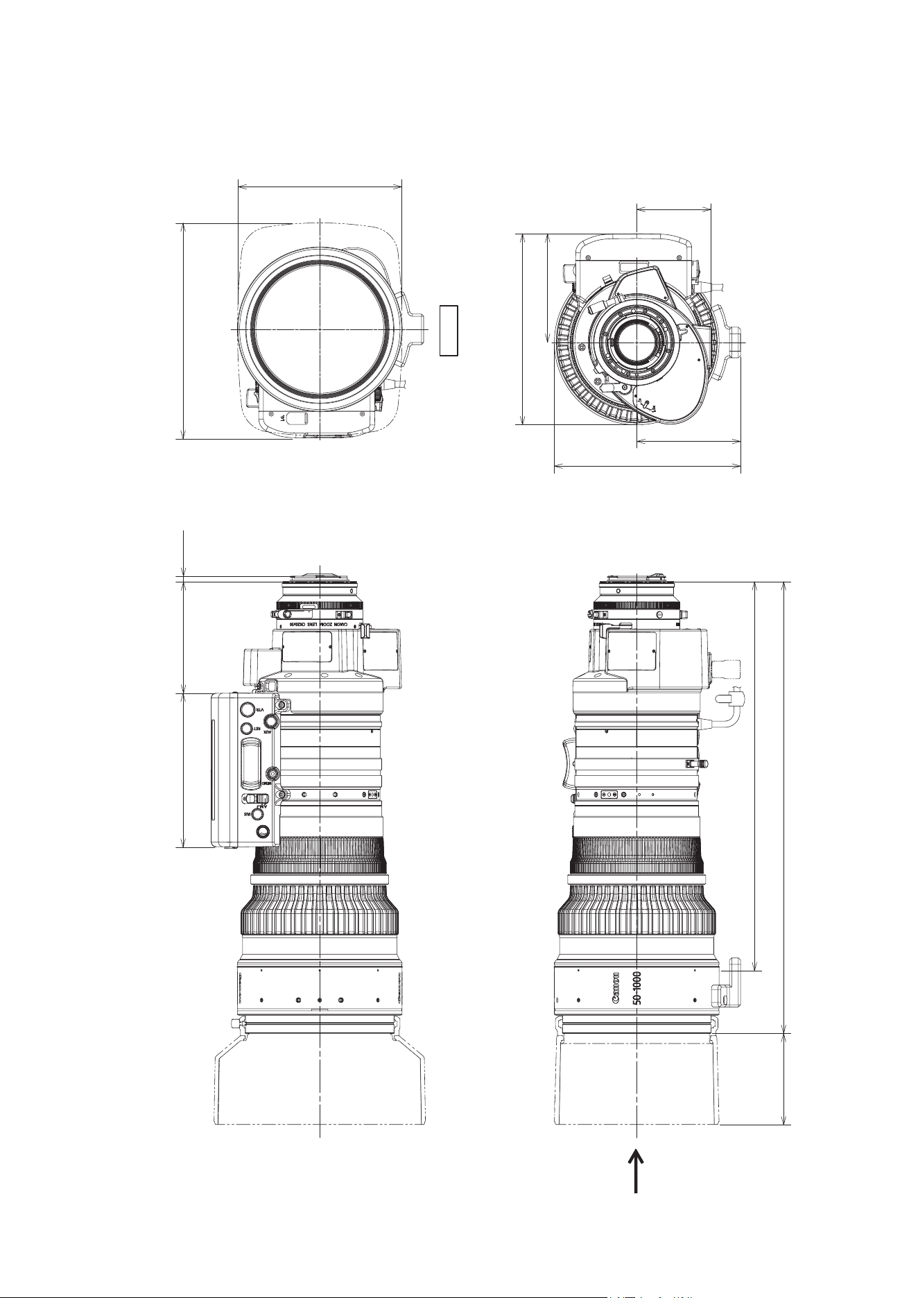
EXTERNAL VIEW
(1) CN20x50 IAS H/E1
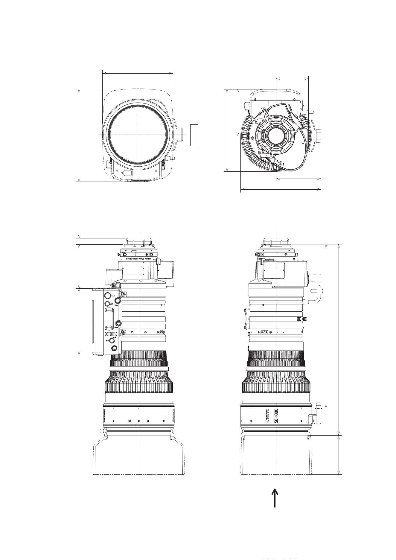
(Unit: mm)
140.8
175
405.2
348.1
83.5
170.6
95.1
99.5
93.7 13.3
(195)
(150.8)
A
68.7
View A
(2) CN20x50 IAS H/P1

Memo

CANON INC.
30-2, Shimomaruko 3-chome, Ohta-ku, Tokyo, 146-8501, Japan
BT1-D025-A-ENG ©2022.09 CANON INC.
