Made in China | 705 -F T43 3C-00
www.godox.com
深圳市神牛摄影器材有限公司
Wechat
Ofcial Account
神牛微信公众号
地址:深圳市宝安区福海街道塘尾社区耀川工业园厂房
2
栋
电话:
0755-29609320
(
8062
)
传真:
0755-25723423
邮箱:
godox@godox. com
合格证
GODOX Photo Equipment Co., Ltd.
Add.: Building 2, Yaochuan Industrial Zone,Tangwei Community, Fuhai Street, Bao'an
District, Shenzhen 518103, China Tel: +86-755-29609320(8062)
Fax: +86-755-25723423 E-mail: [email protected]
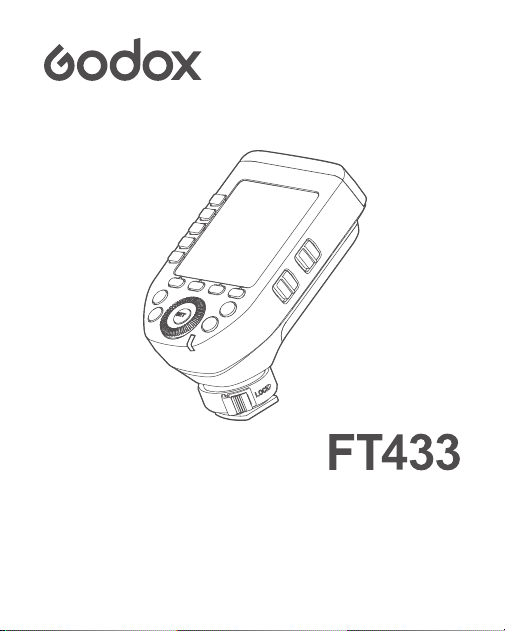
使用手册
Instruction Manual
地址:深圳市宝安区福海街道塘尾社区耀川工业园厂房
2
栋
电话:
0755-29609320
(
8062
)
传真:
0755-25723423
邮箱:
godox@godox. com
TTL 无线引闪器
TTL Wireless Flash Trigger

目录
重要安全提示
前言
部件名称
发射器 FT433
接收器 FR433
发射器 LCD 显示屏
物料清单
电池说明
开关机
省电模式
AF 对焦辅助灯开关
无线设置
无线同步触发外拍闪光灯
模式设置
屏幕锁定
放大功能
档位值设置(功率设置)
曝光补偿设置
01
02
03
06
07
08
08
08
09
10
12
12
12
14

频闪参数值设置 ( 输出值、次数、频率设置 )
造型灯设置
ZOOM 值设置
快门同步设置
蜂鸣器设置
PC 插孔设置
SHOOT 功能设置
蓝牙设置
APP 下载
MENU 菜单
兼容闪光灯型号
兼容相机列表
规格参数
恢复出厂设置
固件升级
注意事项
神牛 433MHz 无线漏闪原因及解决办法
15
16
16
17
18
19
19
20
20
21
24
24
25
27
27
27
28

01
重要安全提示
本产品属于专业摄影设备,需要专业人员操作使用。
使用前必须拆除产品上的所有运输保护材料和包装。
使用时必须遵守以下基本安全预防措施:
使用本产品前,请仔细阅读并完全理解产品说明书,严格按照说明
书中的安全提示操作。
严禁使用损坏的设备或配件,必须等待专业维修人员检查维修并确
认设备正常后,才可继续使用。
在不使用时,请断开电源。
本设备不防水,请保持干燥,不能浸入水或其他液体,应安装在通
风干燥位置,避免在雨天、潮湿、多尘或过热环境中使用。不要在
设备上方放置物品,或让液体流入内部,防止发生危险。
未经授权,请不要自行拆卸本产品。产品若出现故障,必须由本公
司或授权维修人员检查和维修。
请勿将设备放置在酒精、汽油等易燃挥发性溶剂或气体如甲烷、乙
烷等附近。
本设备禁止在有爆炸危险的环境中使用或存放。
清洁设备时,请用干燥软布轻轻擦拭,不可使用湿布,否则可能会
损坏设备。
本使用说明基于严格测试制定,设计和规格变更恕不另行通知。您
可登录我们官方网站查看最新电子版使用说明,了解产品最新资讯。
请勿充电(除非是可充电电池)、或拆卸电池。切勿混用不同类型、
品牌的电池或新旧电池。
本设备整机的保修期为一年,私自维修将取消保修资格,需支付维
修费用。
不当操作导致故障不在保修范围。
1.
2.
3.
4.
5.
6.
7.
8.
9.
10.
11.
12.
02
前言
感谢您购买神牛 TTL 无线引闪器 FT433。
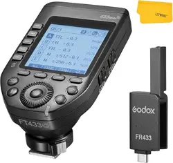
该引闪器以发射器 FT433 组合接收器 FR433 使用,内置 433MHz 无线
模块,做到传输距离更长的同时能极大提高抗干扰能力,为专业摄影师
打造无漏闪的稳定创作空间。
FT433 可 控神 牛 闪 光灯 如:AD200ProII、AD600ProII、AD600BMII 等
全新升级的二代闪光灯 ; 支持 TTL 闪光 /M 手动闪光 /Multi 频闪闪光,
及高速 / 前帘 / 后帘同步方式 , 满足多样化拍摄需求,最大闪光同步速
度达 1/8000s。多频道控制,信号稳定,方便摄影师灵活布光,满足多
种拍摄需求。
发射器 FT433 C 适用于佳能热靴相机 ;
发射器 FT433 S 适用于索尼热靴相机 ;
发射器 FT433 N 适用于尼康热靴相机。
* 限制条件:相机的最大快门速度为 1/8000s
* 兼容相关:FT433 系列发射器与 FR433 接收器兼容使用,不兼容其他型号的引闪器
或接收器
注意 - 进行本说明书未指定的控制或调整或执行程序可能会导致有害辐射。
1 类激光产品
03
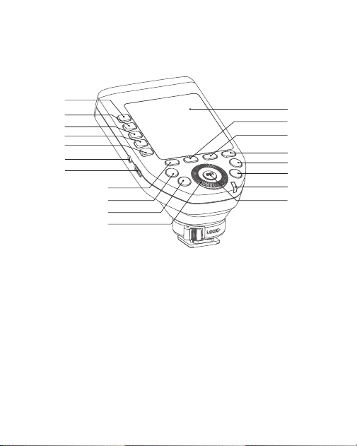
1. 组别按键 1
2. 组别按键 2
3. 组别按键 3
4. 组别按键 4
5. 组别按键 5
6. 功能按键 1
7. 功能按键 2
8. 功能按键 3
9. 功能按键 4
10. MENU 按键
11. 放大按键
12. 状态指示灯
13. SET 按键
14. 调节拨盘
15. 试闪 / 快门按键
16. MODE·LOCK 按键
17. LCD 显示屏
18. 2.5mm 同步插孔
19. USB-C 固件升级接口
部件名称
发射器 FT433
1
7
17
8
9
10
11
12
13
2
3
5
18
19
6
14
15
16
4
状态指示灯为绿色:对焦(相机)
状态指示灯为红色:引闪(闪光灯)+ 快门(相机)
04
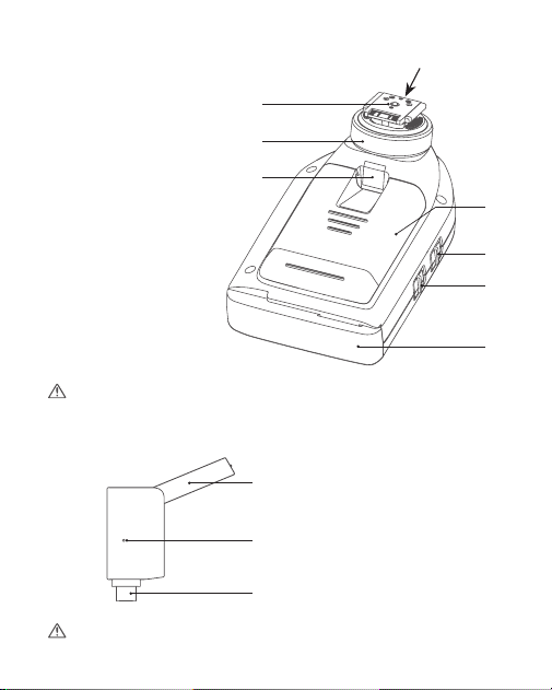
20. 电池盒
21. 电源开关
22. AF 辅助对焦灯开关
23. 热靴
24. 热靴锁环
25. 对焦灯
26. 天线
1. 天线
2.USB-C 接口
3. 指示灯
接收器 FR433
在使用时,请将顶部的天线旋转出来,确保信号传输。
注意 : 适用于不同相机的发射器 , 热靴有所区别。
在使用时,请将顶部的天线旋转出来,确保信号传输。
ON:辅助对焦灯输出
OFF:无辅助对焦灯输出
ON:打开电源
OFF:关闭电源
25
23
20
21
22
26
24
1
2
3
05
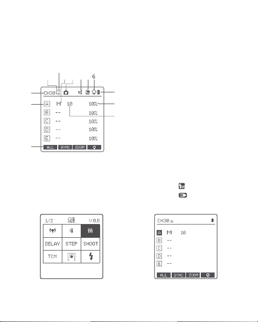
发射器 LCD 显示屏
菜单显示 多组显示
1. 频道(共 32 个频道)
2.ID 识别号(共 99 个识别号)
3. 连接相机
4. 组别模式
5. 蜂鸣器
6. 造型灯总控
7. 电池电量显示
8. 组别造型灯
9. 组别
10. 功能按键对应图标
11. 输出功率档位
12. 高速同步延时
13. 图标显示<
>表示高速同步
图标显示<
>表示后帘同步
1
9
10
11
8
7
2 4 3 5
12
13
06
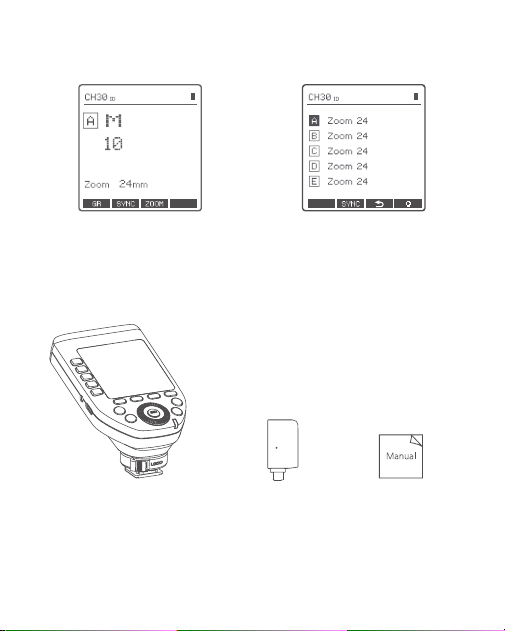
物品清单
引闪器 FT433*1
接收器 FR433*1 说明书 *1
单组显示 多组 ZOOM 显示
07
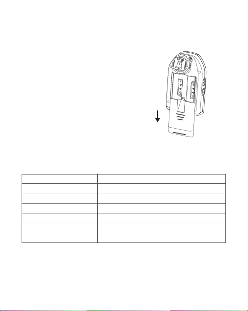
电池说明
安装电池
电池电量指示
手动滑开背面的电池盖,根据电池盒
内的正负极指示,分别装入 2 节 AA
尺寸的碱性或镍氢电池(需另购)。
使用时请查看显示屏上的电池图标,即可随时掌握电量状态。
此电池电量指示只对应 AA 碱性电池,镍氢电池电压偏低,请勿参考此表格。
显示屏上电量符号显示
3格
2格
1格
无格
闪烁
说明
满电
中电
低电
电量少,请及时更换电池。
< 2.5V 电量即将用尽 ( 此时请更换电池,否则
在距离较远时会出现漏闪或不闪现象 )
08
开关机
省电模式
AF 对焦辅助灯开关
正确安装电池后,将电源开关拨至“ON”即可开机,拨至“OFF”即可关机。
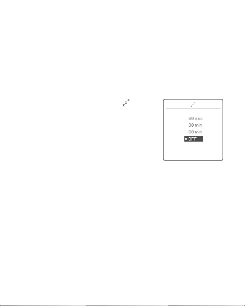
1. 短按 MENU 按键可进入菜单找到
休眠
功能进行设置。
2. 可任意选择一个时间进行自动休眠,如 60
秒 /30 分钟 /60 分钟之后进入休眠,屏幕将自
动熄灭;唤醒可按任意键,屏幕会重新亮起。
3. 若不需要省电模式,可选时间下的 OFF 选
项,即关闭省电模式。
将 AF 辅助对焦灯开关拨至“ON”,允许输出 AF 对焦光线。
相机无法对焦时,对焦灯会自动点亮;相机正常对焦时,对焦灯会自动
熄灭。
当您购买的发射器型号为 FT433 S 时 , 您需进入菜单设置 AF, 使用无反
相机 , 选择“MILC”, 使用单反相机 , 选择“DSLR”。
注 : 长时间不使用时,请关闭电源以免耗电。
09
无线设置
短按 MENU 按键,进入菜单界面。
选中 ,短按 SET 按键进入无线设置,旋转拨盘依次可选 CH、ID、
DIST、GROUPS;旋转拨盘选定其中一项后短按 SET 按键并旋转拨盘进
行具体设置,设置完成再次短按 SET 按键并旋转拨盘可跳入下一栏进行
设置。
无线同步触发外拍闪光灯
使用方法以 AD600ProII 为例:
1. 关闭引闪器、相机、闪光灯的电源,将引闪器 FT433 安装在相机热
靴插座,接收器 FR433 插入 AD600ProII 机身上的 USB-C 接口,然后
将引闪器、相机以及闪光灯的电源都打开。
注:通过改变无线传输频道和无线 ID 号可避免拍摄干扰,主控单位和从控单位的无线
CH、ID、GROUPS 需设一致才能触发。
CH
ID
DIST
GROUPS
1-32
OFF/1-99
1-100m/0-10m
5(A-E)/16(0-F)
可选频道 1 至 32
可选识别号关闭或 1 至 99
可选引闪距离 1 至 100 米或 0 至 10 米
5 组组别:(A、B、C、D、E)
16 组组别:(0、1、2、3、4、5、6、7、
8、9、A、B、C、D、E、F)
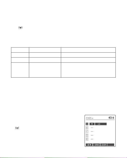
2. 设置 FT433:短按 MENU 按键进入菜单,选
中 后短按 SET 按键设置频道、识别号,设
置完成短按 MENU 按键回到主界面。
短按 MODE·LOCK 按键设置引闪器模式,旋转
拨盘设置引闪器档位参数。
10
模式设置
短按组别按键选中组别,短按 MODE·LOCK 按键,选中的组别模式会
发生变化。
将 GROUPS 组别设置为 5(A-E)(5 组组别),且 <
> 频闪为开启
(ON)时:
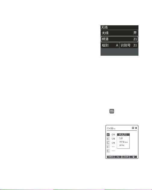
3. 设置 AD600ProII:短按 MENU 按键进入菜单,
选中无线后短按 SET 按键将无线打开,设置同
引闪器一致的频道、组别、识别号。
4. 按下相机快门即可引闪,引闪器状态指示灯会闪亮红色。
注:其他型号外拍闪光灯设置请根据相应的外拍闪光灯使用说明书。
1. 多组模式显示时,短按 MODE·LOCK 按键,
多组显示模式可以切换为 MULTI(频闪)模
式,短按组别选择按键选中某组组别,短按
MODE·LOCK 按键将该组 MULTI 模式设为打
开 (ON) 或关闭 (--)。
短按组别按键取消选中后,再次短按
MODE·LOCK 按键可退出 MULTI(频闪)模式。
11
2. 多组模式显示时,短按组别选择按键选中
某组组别后,短按 MODE·LOCK 按键可切换
模式,当前组可切换 TTL/M/--。
3. 短按放大按键,单组模式显示,短按
MODE·LOCK 按键可切换当前组模式,可切
换至 ETTL/M/OFF(FT433 C)。
单组模式显示 , 短按 <MODE.LOCK> 按
钮可切换当前组模式 , 可切换至 TTL/M/
OFF(FT433 S、FT433 N)。
注:TTL 表示自动闪光,M 表示手动闪光、-- 表示模
式关闭。
1. 多组模式显示和单组模式显示,仅有 M 手
动模式。
将 GROUPS 组别设置为 16(0-F)(16 组组别):
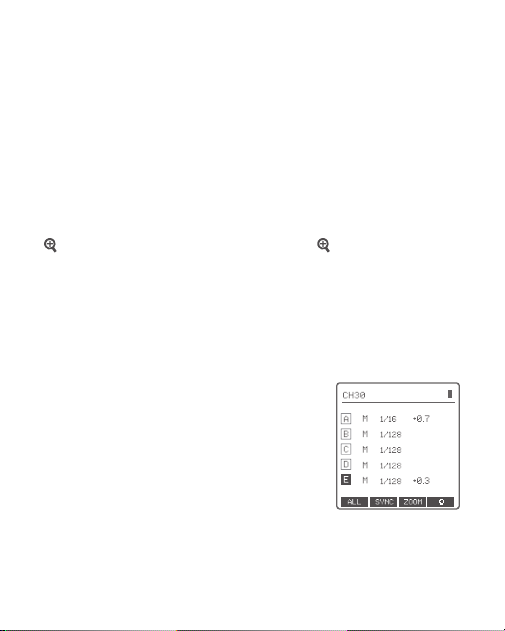
12
屏幕锁定
放大功能
长按 MODE·LOCK 按键,屏幕下方出现“LOCKED”,表示当前屏幕已被
锁定,此时不能再设置任何参数;再次长按 2 秒 MODE·LOCK 按键,
屏幕下方“LOCKED”消失,即解锁成功。
多组显示切换至单组显示:在多组模式下短按组别按键选定组别,短按
放大按键,组别放大到单组显示模式,短按 放大按键可返回多组
显示模式。
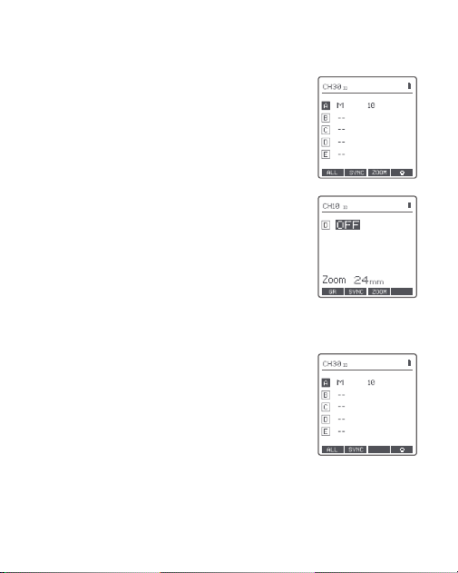
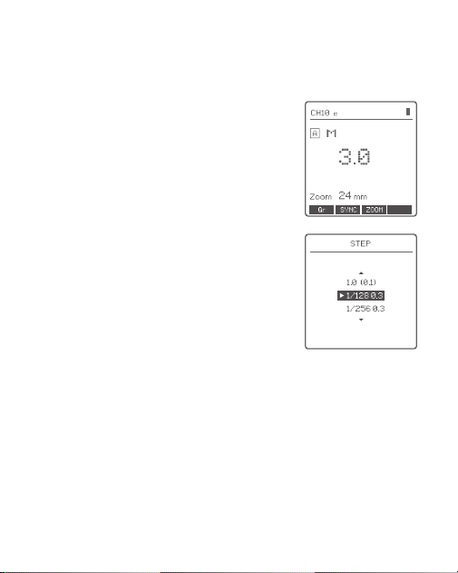
多组显示时,在 M 模式下
档位值设置(功率设置)
1. 短按组别按键选中组别,旋转拨盘,其功
率输出值将在 Min.~1/1 或 Min.~10 之间变
化,每档都以 0.1 档或 1/3 档为增量。最后
短按 SET 按键确定该组功率输出值。
2. 短按功能按键 1(ALL 按键)全组功率输
出值会被选中,旋转拨盘,其功率输出值将
在 Min.~ 1/1 或 Min.~10 之间变化,且每档
以 0.1 档或 1/3 档为增量,最后短按功能按
键 1(ALL 按键)确定全组功率输出值。
13
注:Min. 指 M 或 Multi 模式下能设置的最小输出
值。根据菜单中 STEP 设置的值不同,Min. 值不同。
最小功率输出档位(STEP)选择一共有 9 种,分别
为 1/128 0.3、1/256 0.3、1/512 0.3、1/128 0.1、
1/256 0.1、1/512 0.1、3.0(0.1)、2.0(0.1)、1.0(0.1)。
单组显示时,在 M 模式下
1. 旋转拨盘,其功率输出值将在 Min.~ 1/1
或 Min.~10 之间变化,每档都以 0.1 档或
1/3 档为增量。
注:M 模式为手动闪光模式。
14
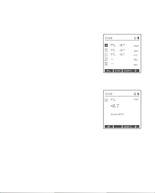
多组显示时,在 TTL 模式下
曝光补偿设置
1. 短按组别按钮选中组别,旋转拨盘,其
FEC 值在 -3 ~ 3 之间以 0.3 为增量,短按
SET 按键确定该组 FEC 值。
2. 短按功能按键 1(ALL 按键),全组 FEC
值会被选中,旋转拨盘,其 FEC 值在 -3 ~
3 之间以 0.3 为增量 ,,再次短按功能按键 1
(ALL 按键)确定全组 FEC 值。
单组显示时,在 TTL 模式下
1. 旋转拨盘,其 FEC 值在 -3 ~ 3 之间以 0.3
为增量。
注:TTL 模式为自动闪光模式,FEC 值为曝光补偿值。
SYNC
15
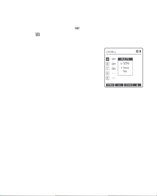
1. 在频闪模式下 (TTL 和 M 图标都不会显示 )。
2. 三行显示内容分别为功率输出值 (Min. ~
1/4 或 Min. ~ 8.0 ),Times( 闪光次数 ),
Hz( 闪光频率 )。
3. 旋转拨盘,其功率输出值将在 Min. ~ 1/4
或 Min. ~ 8.0 之间以整档变化。
4. 短按功能按键 1(TIMES 按键 ),旋转拨盘
调整闪光次数(1-100)。
5. 短按功能按键 2(HZ 按键),旋转拨盘
调整闪光频率(1-199)。
6. 设置任意项目或三项设置值设置完毕,短
按 MODE·LOCK 按键,将退出频闪参数值
设置界面。
注:闪光次数受闪光输出值和频率联合制约,设置的
闪光次数不能超过系统允许的上限值。传输到接收端
的次数是实际闪光次数,同相机的快门设置相关。
频闪参数值设置 ( 输出值、次数、频率设置 )
设置频闪参数前提:进入菜单中的 无线设置,GROUPS需选中5(A-E),
且菜单中的 频闪设置需设为 ON( 开启)。
在多组显示下,短按 MODE·LOCK 进入频闪参数值设置界面。
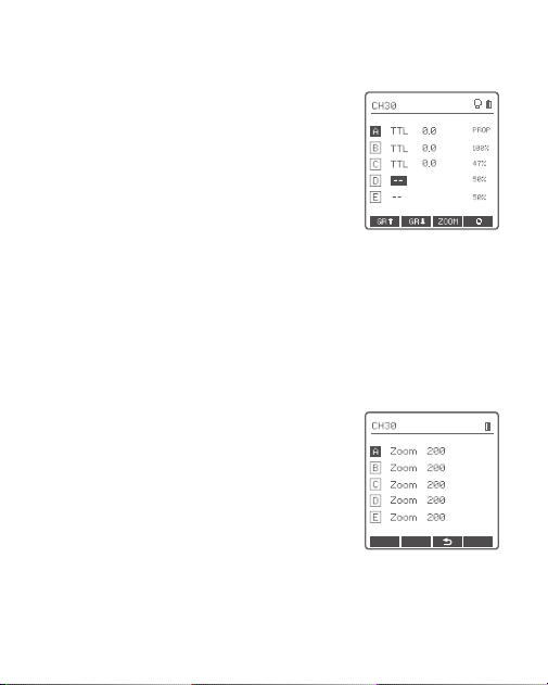
16
造型灯设置
1. 多组显示时,短按功能按键 4,实现多组
造型灯打开或关闭。
2. 多组显示且造型灯总控打开时,短按组别
按钮选中组别。短按功能按键 4,可切换该
组造型灯状态,一共 3 种状态:关闭(--)
或百分比数值 (10% -100% ) 或 PROP(自
动模式,随着闪光灯亮度而发生变化)。
3. 造型灯处于百分比数值状态时,长按功能
按键 4 进入造型灯亮度值设置界面,旋转拨
盘选择所需百分比数值。
4. 单组显示时,与上述多组显示操作同理。
ZOOM 值设置
短按功能按钮 3,显示屏出现 ZOOM 值,短
按组别按键选中要更改的组别,旋转拨盘,
ZOOM 值会在 AUTO/24-200 中变化,选中
需要设定的 ZOOM 值,最后短按功能按键 3
返回主界面。
注:当无线设置中的的 GROUPS(组别)设为 16(0-F)
(16 组组别)时,无论多组显示还是单组显示,都
不可设定 ZOOM 值。
17
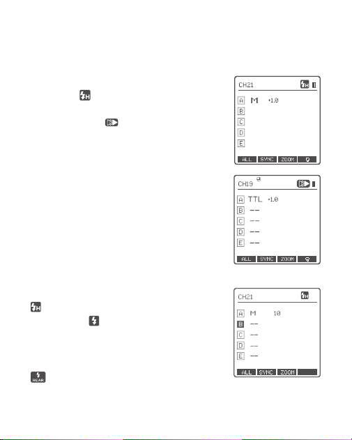
快门同步设置
FT433 C
FT433 S
1. 高速同步:短按显示 SYNC 下的功能按键,
令屏幕显示
。
2. 后帘快门同步:短按显示 SYNC 下的功能
按键,令屏幕显示
。
1. 高速同步:按 <SYNC> 按键,令屏幕显示
。在 SONY 相机上按 MENU 按键或 Fn
快捷键进闪光
模式选择强制闪光后设置
相机快门。
2. 后帘同步:直接在相机上按 MENU 按键
或 Fn 快捷键进闪光模式选择后帘同步闪光
后再设置相机快门。
18
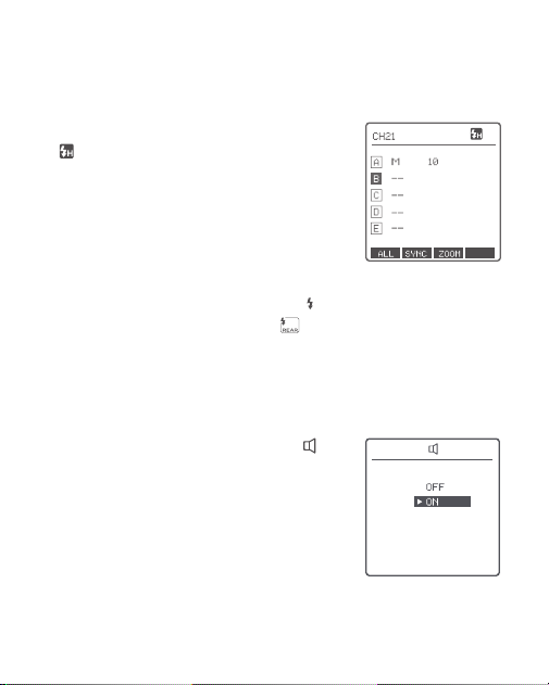
蜂鸣器设置
短按 MENU 按键进入菜单,旋转拨盘至 ,
短按 SET 按键进入蜂鸣器设置,旋转拨盘可
选 OFF 或 ON,设置完成短按 MENU 按键返
回主菜单。
选择 ON 时,蜂鸣器启动。
选择 OFF 时,蜂鸣器关闭。
FT433 N
1. 高速同步:按 <SYNC> 按键,令屏幕显示
<
> 。在尼康相机机身设置中,将快门同
步速度设置为 1/320 秒 ( 自动 FP) 或 1/250
秒 ( 自动 FP),转动相机拨盘,快门速度能设
置为 1/250s 或更高快门速度,要确认目前是
否正在使用 FP 高速同步功能,通过相机取
景器检查快门速度即可判断,如果快门速度
为 1/250s 或者更高,表示高速同步启动。
2. 后帘快门同步:在 Nikon 相机上按住 < >,
旋转主指令拨盘至控制面板中出现 <
>后
帘闪光模式,再设置相机快门。
19
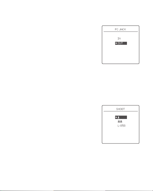
PC 插孔设置
短按 MENU 按键进入菜单,旋转拨盘至 PC,
短按 SET 按键进入 PC 插孔设置,旋转拨盘
可选 IN 或 OUT,设置完成短按 MENU 按键
返回主菜单。
选择 IN 时,相机触发引闪器。
选择 OUT 时,引闪器触发闪光灯。
SHOOT 功能设置
短按MENU 按键进入菜单,旋转拨盘至,短按 SET 按键进入 SHOOT设置,
旋转拨盘可选择单拍 / 多拍 /L-858,设置完成短按 MENU 按键返回主
菜单。
单拍:
相机拍照时选择单拍,在 M 和 Multi
模式下,主控单元只对从控单元发送引闪信
号,适合单人拍摄时选用,优点省电。
群拍:
相机拍照时选择群拍,主控单元会将
参数和引闪信号发送至从控单元,适合多人
拍摄时选用,此功能耗电快。
L-858:
使用 L-858 测光表直接设置闪光灯
数据,引闪器只发射同步信号。当开启 L-858
后主界面显示 L-858,此时仅有引闪功能,
无法调节参数。
20
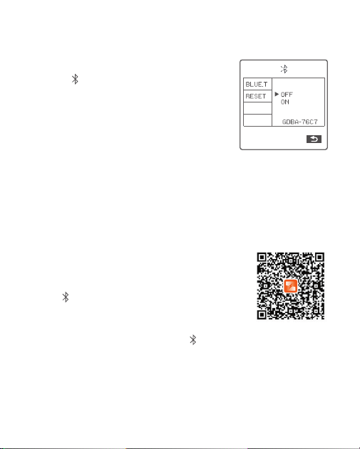
蓝牙设置
蓝牙开关:
短按 MENU 按键进入菜单,旋
转拨盘至
,短按 SET 按键进入蓝牙设置,
选中 BLUE.T.E 后短按 SET 按键选择 OFF(关
闭蓝牙)或 ON(开启蓝牙),按下 SET 按
键确认该选项,蓝牙 MAC 码显示在右下角。
蓝牙重置:
旋转拨盘选中 RESET 后短按 SET
按键选择 CANCEL(取消重置)或 RESET(确
认重置),按下 SET 按键确认该选项。
APP 下载
扫描二维码即可下载“Godox Flash”手机 APP( 支持 iOS 和安卓系统使用 )
1. 设置引闪器:进入菜单将蓝牙功能开启,右
下方也可见蓝牙 MAC 码。
2. 设置手机 APP:下载 APP,在打开的 APP
中选择
连接。连接引闪器对应的蓝牙
MAC 码,输入密码进行配对,初始密码为:
000000,显示蓝牙连接成功后返回 APP 首页。
3.开启蓝牙功能后,引闪器主界面出现 图标。
4. 调节从属闪光灯的频道、识别号与引闪器一
致,就可以在手机 APP 里调节从属闪光灯的
参数。
注:首个移动设备 ( 手机或平板电脑 ) 可直接使用 APP 操控灯体。更换其他移动设备 ( 手
机或平板电脑 ) 时,灯体需进行蓝牙重置后,方可正常使用 APP 连接。
21
MENU 菜单
选项
CH
ID
DIST
GROUPS
BLU E.T.
RESET
ON
OFF
OFF
0.1ms-9.9ms
1/128 0.3
1/256 0.3
1/512 0.3
1/128 0.1
1/256 0.1
1/512 0.1
3.0 (0.1)
2.0(0.1)
1.0 (0.1)
功能
无线
蓝牙
频闪
高速同步
延时
档位(功
率)
符号
DELAY
STEP
说明
32 组:1-32
OFF:关闭
1-99:可以选择 1-99
1-100m:1-100 米引闪
0-10m:0-10 米引闪
5(A-E):5 组组别
16(0-F):16 组组别
OFF: 关闭蓝牙
ON: 开启蓝牙
CANCEL: 取消操作
RESET: 重置蓝牙
开启频闪
关闭频闪
关闭高速同步延时
高速同步延时范围
最小输出档位 1/128( 每档以 1/3 档为增量 )
最小输出档位 1/256( 每档以 1/3 档为增量 )
最小输出档位 1/512( 每档以 1/3 档为增量 )
最小输出档位 1/128( 每档以 0.1 为增量 )
最小输出档位 1/256( 每档以 0.1 为增量 )
最小输出档位 1/512( 每档以 0.1 为增量 )
最小输出档位 3.0( 每档以 0.1 为增量 )
最小输出档位 2.0( 每档以 0.1 为增量 )
最小输出档位 1.0( 每档以 0.1 为增量 )
22
选项
OFF
100j
200j
300j
360j400j
600j
1200j
OFF
ON
TRIGGER
SHUTTER
IN
OUT
功能
单拍
群拍
L-858
TCM 转换
功能
传统热靴
试闪按键
PC 端口
符号
SHOOT
TCM
说明
相机拍照时在 M&Multi 模式下只发送引闪
信号
相机拍照时发送参数和引闪信号 ( 适合多人
拍摄 ),接收端有 X1R-C 接收器,请勿使用
群拍模式。
使用 L-858 测光表直接设置闪光灯数据,引
闪器只发射同步信号。当开启 L-858 后主界
面显示 L-858,此时仅有引闪功能,无法调
节参数。
关闭 TCM 转换功能
TT685II/V860III 系列
AD100Pro
AD200
AD300Pro
AD400Pro
AD600、AD600Pro
AD1200Pro
关闭传统热靴
启动传统热靴,不支持 TTL 闪光,无高速同
步闪光,无频闪闪光。
引闪器试闪
快门试闪
输入端,相机触发引闪器
输出端,引闪器触发闪光灯
使 TTL 闪光值转换
为 M(手动闪光)
功率值 , 混用时以主
灯型号为准。TCM
转换功 能开启后 , 短
按 MODE·LOCK 按
键可进行 TCM 转换
23
选项
MILC
DSLR
OFF
ON
60sec
30min
60min
OFF
12sec
OFF
ON
-3 至 +3
SAVE
LOAD
CANCEL
CLEAR
功能
辅助对焦灯
蜂鸣器
休眠
背光
LCD 对比度
使用预设
清除数据功能
符号
AF
(FT433 S)
说明
使用无反相机时 , 选择此项对焦灯才会
自动点亮 ( 对焦灯开启时 )
使用单反相机时 , 选择此项对焦灯才会
自动点亮 ( 对焦灯开启时 )
关闭蜂鸣器
开启蜂鸣器
60 秒无人操作,进入休眠
30 分钟无人操作,进入休眠
60 分钟无人操作,进入休眠
关闭休眠功能
12 秒无人操作,自动熄灭 LCD 背光
关闭 LCD 背光
一直开启 LCD 背光
对比度值范围:-3 到 +3 之间的 整数
保存组:1-5
导入组:1-5
取消操作
清除菜单数据
注:短按 对应的功能按键 4 可返回上一级设置。
Z
Z
Z
LIGHT
USER
CLEAR
24
兼容闪光灯型号
兼容相机列表
闪光灯型号
AD200ProII、AD600ProII、AD600BMII
接收器
FR433
发射器
FT433
备注
支持的功能范围:FT433 和闪光灯双方都拥有的功能。
FT433 C 发射器可兼容以下佳能 EOS 系列的相机型号
FT433 S 发射器可兼容以下索尼相机型号
1. 此表格仅列举目前已测试的相机型号,未涵盖所有佳能 EOS 系列的
相机型号。其他相机型号,用户可自行测试。
2.EOS R 系列相机中,部分相机在 TTL 高速同步闪光时,主闪会异常过
曝。
3. 本公司保留未来修改此表格内容的权利。
1. 此表格仅列举目前已测试的相机型号,未涵盖所有索尼相机。
其他相机型号,用户可自行测试。
2. 本公司保留未来修改此表格内容的权利。
5D Ⅲ、5D Ⅳ、60D、70D、80D、1DX、1DX2、850D、760D、
5D Ⅱ、7D Ⅱ、6D Ⅱ、6D、800D、90D、600D、7D、3000D、
1500D、200D Ⅱ、M5、M3、M6 Ⅱ、EOS RP、EOS R、R5、R6 Ⅱ、R7
a77 II、 a77、 a99、 ILCE-6000L、 a9、A7R、A7RIII、a350、
DSC-RX10、A7IV、A7C、A7M4
25
FT433 N 发射器可兼容以下尼康相机型号
1. 此表格仅列举目前已测试的相机型号,未涵盖所有尼康相机。
其他相机型号,用户可自行测试。
2. 本公司保留未来修改此表格内容的权利。
D5、D4、D60、D70S、D90、D100、D200、D300S、D300、
D500、 D610、D700、D750、D800、D810、D3100、D3200、
D3300、D5000、D5100 D5200、D5300、D7000、D710、Z6、
Z6II、Z7II D780 Zfc
规格参数
发射器
型号
兼容相机
同步孔触发
供电方式
TTL 自动闪光
手动闪光
频闪闪光
高速同步
后帘同步
曝光补偿
曝光锁定
FT433 C
佳能相机
支持所有具有 PC 输出口的相机
2*AA 电池(另购)
√
√
√
√
√ (FT433 S 和 FT433 N 需在相机上设置 )
±3EV(曝光值),以 1/3EV 为增量调节
具备
FT433 S
索尼相机
FT433 N
尼康相机
26
型号
尺寸
净重
接收器
FR433
≈ 25mm*50mm*13mm
≈ 10g
规格和参数如有变更 , 恕不另行通知。
辅助对焦
造型闪光
蜂鸣器
无线快门
ZOOM 设置
TCM 转换
固件更新
记忆功能
显示屏
传输范围(约)
内置无线
调制方式
频道
无线 ID
组别
尺寸
净重(不含电池)
具备 ( 需相机支持该功能 )
可以通过引闪器控制闪光灯造型闪光 (FT433 S 不
支持此功能 )
可以通过引闪器控制闪光灯蜂鸣器
接收器端可以通过 2.5mm 同步接口控制相机拍摄
AUTO/ 焦距 24-200mm
使 TTL 拍摄值转换为 M 输出值
通过机身上的 USB-C 口进行固件升级
设置 2 秒后的参数会自动记忆,重新开机自动恢复
宽屏液晶显示,可开启或关闭背光
0-100 米
433MHz
GFSK
32 个
OFF/1-99
5 组或 16 组(在菜单中可选)
≈ 62mm*101mm*49mm
≈ 97g
27
恢复出厂设置
固件升级
同时按住中间两个功能按键 2 秒,屏幕出现 RESET,下方有 CANCEL
和 OK 两个选项,旋转拨盘选择 OK,短按 SET 按键,约两秒后自动返
回主界面表示已恢复出厂设置。
FT433C: 本设备包含型号核准代码为 :CMIIT ID: 24J44811A011, 为该产品的无线电发
射模块。
本机通过 USB-C 口可进行固件升级,软件最新公告及说明将会发布在
官方网站上。
本品出厂不配 USB 升级线,请另行购买。本产品升级固件需要 Godox
G3 V1.1 程序软件支持,升级固件前请先下载安装“Godox G3 V1.1 固件
升级软件”再选择相应的固件文件。由于产品进行固件升级,说明书请
以最新电子版为准。
注意事项
1. 如不能正确引闪或拍摄,请检查是否打开引闪器电源;引闪器是否设
置在同一频道;连接线或热靴口是否已正确牢固连接到位;功能模式是
最大输出功率
发射波长
激光等级
激光模组资料如下
<390μW
650nm±10nm
1 类

28
神牛 433MHz 无线漏闪原因及解决办法
→请调节引闪器的频道 CH 设置 ( 建议 +10) 找到无干扰的频道,或者
在工作时关闭其他 433MHz 设备。
→请在引闪器上打开“近距离无线模式”
FT433 系列:进入菜单 - 无线设置 -DIST 设为 0-10m。
→请下调闪光灯档位,如是 TTL 模式请尝试改为 M 模式 (TTL 模式下需
要预闪一次 )。
1. 外部环境 433MHz 信号干扰 ( 如无线基站、路由、蓝牙设备等 )
3. 是否引闪器和闪光灯距离太近(距离 <0.5m)
2. 请确认闪光灯是否已经回电或回电速度是否跟上连拍速度,并且没有
处于过热保护或者其他异常状态中。
→请更换电池或充电处理,确保引闪器和闪光灯设备电量充足。
4. 是否引闪器和接收端设备在低电状态
→请升级引闪器固件 , 具体升级请参考固件升级。
5. 引闪器固件为旧版本
否设置正确。
2. 如相机出现只能拍摄不能对焦现象,请检查机身或镜头是否设定为
MF 手动对焦,请设置为 Af 自动对焦。
3. 如您的引闪器受到他人干扰引闪或拍摄,改变引闪器的频道设置即可。

29
Contents
Important Safety Instructions
Foreword
Names of Parts
What’s Inside
Battery Instruction
Power Switch
Power Saving Mode Settings
Power Switch of AF Assist Beam
Wireless Settings
As a Wireless Outdoor Flash Trigger
Mode Settings
Screen Lock
Magnication Function
Output Value Settings (Power Settings)
Flash Exposure Compensation Settings
Multi Flash Settings (Output Value, Times and Frequency)
31
33
34
37
38
39
39
39
40
40
41
43
43
43
45
46

30
47
48
48
50
50
51
52
52
54
57
58
59
60
61
61
62
Modeling Lamp Settings
ZOOM Value Settings
Shutter Sync Settings
Buzz Settings
PC Socket Settings
SHOOT Function Settings
Bluetooth Settings
APP Downloading
MENU: Setting Custom Functions
Compatible Flash Models
Compatible Camera Models
Technical Data
Restore Factory Settings
Firmware Upgrade
Attentions
The Reason & Solution of Not Triggering in Godox 2.4G Wireless

31
Important Safety Instructions
This product is a professional photographic equipment, to be operated by
professional personnel only.
All transport protective materials and packaging on the product must be
removed before use.
The following basic safety precautions must be followed when using this
product:
Carefully read and fully understand the instruction manual before use and
strictly follow the safety instructions.
Dot not use damaged equipment or accessories. Allow professional repair
technicians to inspect and conrm normal operation before continuing use
after repairs.
Turn off power when not in use.
This device is not waterproof. Keep it dry and avoid immersing it in water
or other liquids. It should be installed in a ventilated and dry location and
avoid using in rainy, humid, dusty, or overheated environments. Do not
place items above the device or allow liquids to flow into it to prevent
danger.
Do not disassemble without authorization. If the product malfunctions,
it must be inspected and repaired by our company or authorized repair
personnel.
Do not place the device near alcohol, gasoline, or other flammable volatile
solvents or gases such as methane and ethane.
Do not use or store this device in potentially explosive environments.
Clean gently with a dry cloth. Do not use a wet cloth as it may damage the
device.
This instruction manual is based on rigorous testing. Changes in design
and specications are subject to change without notice. Check ofcial
1.
2.
3.
4.
5.
6.
7.
8.
9.
32
10.
11.
12.
Caution - Use of controls or adjustments or performanceof procedures otherthan those
specied herein may result inhazardous radiation.
website for latest instruction manual and product updates.
Do not charge (unless it is a rechargeable battery), or disassemble the
battery. Do not mix different types or brands of batteries or old and new
batteries.
The warranty period for this device as a whole is one year. Consumables
(such as batteries), adapters, power cords, and other accessories are not
covered by the warranty.
Failures from improper operation is not covered under warranty.
CLASS 1 LASER PRODUCT

33
Foreword
Thank you for purchasing!
This TTL wireless flash trigger FT433 is designed to use with most popular
cameras on the market. With built-in 433MHz wireless module, the
transmitter FT433 can be collocated with the receiver FR433 to achieve longer
transmission distance while greatly decreasing the interference.
FT433 can control upgraded Godox flashes such as AD200ProII, AD600ProII
and AD600BMII, supports TTL flash/M (manual) flash /Multi flash, and HSS/
rst-curtain sync/second-curtain sync. Other features such as maximum
flash synchronization speed up to 1 / 8000s, multiple channel control,
stable transmission signal together make it a perfect choice for professional
photographers.
Transmitter FT433 C is compatible with Canon camera hot shoes.
Transmitter FT433 S is compatible with Sony camera hot shoes.
Transmitter FT433 N is compatible with Nikon camera hot shoes.
* Restrictions: 1/8000s is achievable when the camera has a max camera shutter speed of
1/8000s.
* Compatibility: transmitter FT433 is compatible with receiver FR433, other models of flash
triggers or receivers are incompatible.
34
Names of Parts
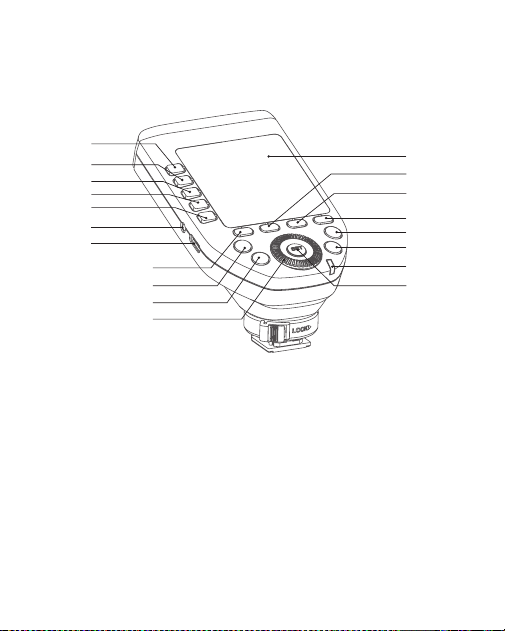
Transmitter FT433
1. Group Button 1
2. Group Button 2
3. Group Button 3
4. Group Button 4
5. Group Button 5
6. Function Button 1
7. Function Button 2
8. Function Button 3
9. Function Button 4
10. MENU Button
11. Magnication Button
12. Status Indicator Lamp
13.SET Button
14. Select Dial
15. TEST/Shutter Button
16. MODE·LOCK Button
17. LCD Panel
18. 2.5mm Sync Cord Jack
19. USB-C Firmware Upgrade Port
Green: Focus (Camera)
Red: Trigger (Flash)+ Shutter (Camera)
1
7
17
8
9
10
11
12
13
2
3
5
18
19
6
14
15
16
4
35
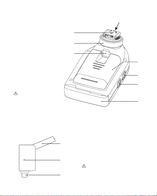
Receiver FR433
20. Battery Compartment
21. Power Switch
22. AF Assist Beam Switch
23. Hot Shoe
24. Hot Shoe Locking Ring
25. Focus Assist Lamp
26. Antenna
Please rotate the top
antenna out in using
to ensure the signal
transmission.
Note: Different transmitters have different hot
shoes to suitable for different camera brands.
Please rotate the top antenna
out in using to ensure the signal
transmission.
1. Antenna
2.USB-C Port
3. Indicator
ON: (AF Assist Beam outputs)
OFF: (AF Assist Beam do not outputs)
ON: (Power On)
OFF: (Power Off)
1
2
3
25
23
20
21
22
26
24
36
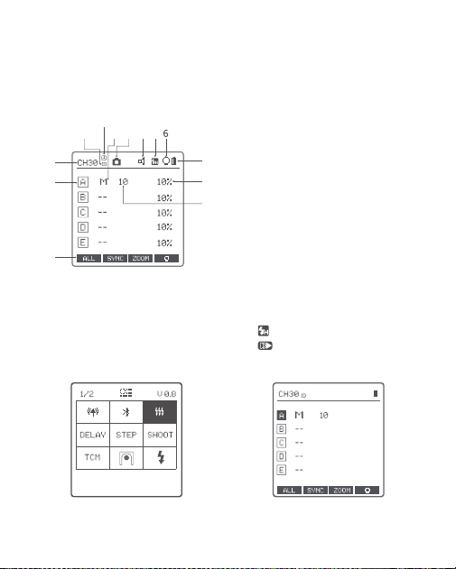
Transmitter's LCD Panel
1. Channel (32)
2. ID (99)
3. Camera Connection
4. Group Mode
5. Beeper
6. Modeling Lamp Master Control
7. Battery Level Indication
8. Group’s Modeling Lamp
9. Group
10. Icons of Function Button
11. Output Power Level
12. HSS Delay
13. <
> means High Speed Sync
<
> means Second Curtain Sync
Menu Display Multi Groups Display
1
9
10
11
8
7
2 4 3 5
12
13
37
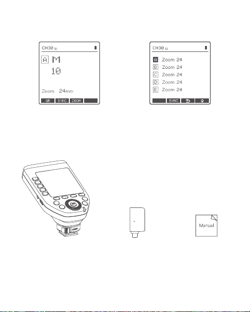
What’s Inside
Single Group Display
Transmitter FT433*1 Receiver FR433*1 Instruction Manual*1
Multi Groups’ ZOOM Display
38
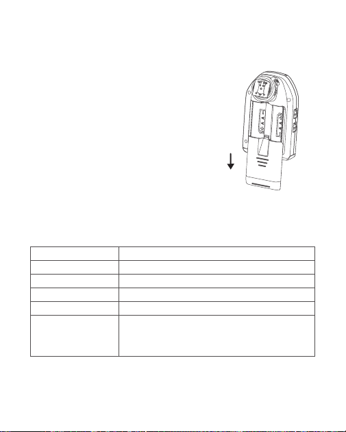
Battery Instruction
Slide the battery compartment lid of the flash
trigger and insert two AA alkaline batteries or Ni-
MH batteries (optional) separately to the correct
polarities.
Check the battery level indication on the LCD panel to see the remaining
battery level during the usage.
The battery indication only refers to AA alkaline batteries. As the voltage of Ni-MH battery tends
to be low, please do not refer to this chart.
Battery Level Indication
3 grids
2 grids
1 grid
Blank grid
Blinking
Power Status
Full
Middle
Low
Low power, please replace it.
<2.5V The battery level is going to be used out immediately
(please replace new batteries, as low power leads to no flash
or flash missing in case of long distance).
Battery Installation
Battery Level Indication
39
Power Switch
Power Switch of AF Assist Beam
Power Saving Mode Settings
Install the battery correctly, slide the power switch button to “ON” can turn on
the product, slide it to “OFF” to turn off.
Note: When not in use for a long time, please turn off the power to avoid power consumption.
Push the AF assist beam switch up to“ON”, and the AF lighting is allowed
output.
When the camera cannot focus, the AF assist beam will turn on; when the
camera can focus, the AF assist beam will turn off.
For transmitter FT433 S, you need to enter the menu to set AF, and select
“MILC” for mirrorless cameras or “DSLR” for DSLR cameras.
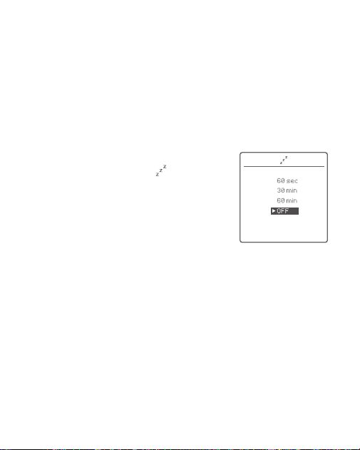
1. Press the MENU button and turn the select dial
to set the auto standby time in <
>.
2. The system will automatically enter standby
mode after 60sec/30min/60min of idle use. And
the displays on the LCD panel will disappear.
Press any button to wake up.
3. If you don't want to set the power saving
mode, select OFF.
40
Wireless Settings
As a Wireless Outdoor Flash Trigger
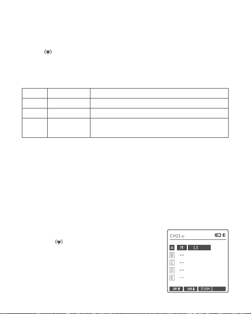
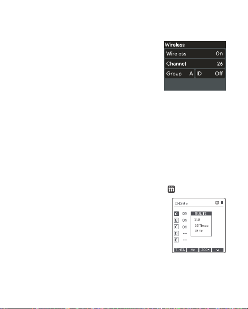
Press the MENU button to enter menu interface.
Select <
> and press the SET button to enter wireless settings, turn the
select dial to choose among CH, ID, DIST and GROUPS. Press the SET button
and turn the select dial to set the corresponding parameters, then press the
SET button again and turn the select dial to the next parameter.
Take AD600ProII as an example:
1. Turn off the flash trigger, camera and flash, mount the transmitter FT433 on
camera hotshoe, insert the receiver FR433 into the USB-C port of AD600ProII.
Then, power on the flash trigger, camera and flash.
Note: You can change the wireless transmission channel and wireless ID to avoid interference.
The wireless channel, ID and groups of l the transmitter and the receiver units must be
consistent before triggering.
Channel choosable from 1 to 32
ID off or 1 choosable from 1 to 99
Triggering distance adjustable from 1m to 100m or 0 to 10m
5 groups: A, B, C, D, E
16 groups: 0, 1, 2, 3, 4, 5, 6, 7, 8, 9, A, B, C, D, E, F
1-32
OFF/1-99
1-100m/0-10m
5 (A-E) /16 (0-F)
CH
ID
DIST
GROUPS
2. Set FT433: Short press the MENU button
and select < > to set channel and ID. Then
short press the MENU button to return the main
interface. Short press <MODE·LOCK> button to
set flash trigger mode, turn the select dial to set
flash trigger level.
41
3. Set AD600ProII: Short press the MENU button,
select wireless then short press the SET button
to turn on wireless, set the same channel, group
and ID to the flash trigger.
4. Press the camera shutter to trigger and the status lamp of the flash trigger
turns red synchronously.
Note: please refer to the relevant instruction manual when setting the outdoor flashes of other
models.
Mode Settings
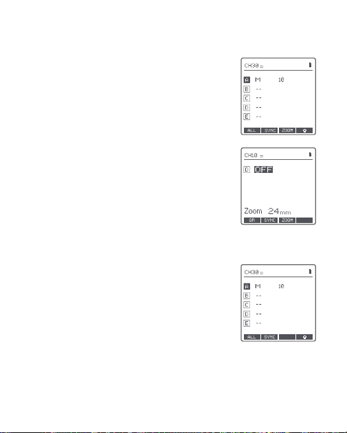
Short press the group button to choose group, then short press
<MODE·LOCK> button, the mode of the chosen group will change.
Set the WIRELESS-GROUPS to ve groups (A-E) and <
> is ( ON ):
1. When displaying multiple groups, short press
the <MODE·LOCK > button to switch the multi-
group mode to MULTI mode. Press the group
selection button to choose a group, short press
<MODE·LOCK > button can set the MULTI mode
to ON or OFF (--).
Short press the group button to cancel the
selection, then short press <MODE·LOCK >
button can exit MULTI mode.
42
2. When displaying multiple groups, press the
group selection button to choose a group, short
press <MODE·LOCK > button to switch among
TTL/M/--.
3. For FT433 C, short press magnication button
to display single group, short press <MODE·LOCK >
button to switch among ETTL/M/OFF.
For FT433 S and FT433 N, short press
magnication button to display single group, short
press <MODE·LOCK > button to switch among
TTL/M/OFF.
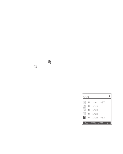
1. When displaying multiple groups or single
group, there is only M manual mode.
Set the groups to 16 groups (0-F):
Note: TTL means auto flash, M means manual flash, --
means off.
43
Screen Lock
Magnication Function
Long press the <MODE·LOCK > button until “LOCKED” is displayed on
the bottom of the LCD panel, which means the screen is locked and no
parameters can be set. Long press the <MODE·LOCK > button for 2 seconds
again to unlock.
Switch between multi-group and single-group mode: choose a group in multi-
group mode and press the <
> button to magnify it to single-group mode.
Then, press the < > button to back to multi-group.
Output Value Settings (Power Settings)
Multi-group displays in the M mode
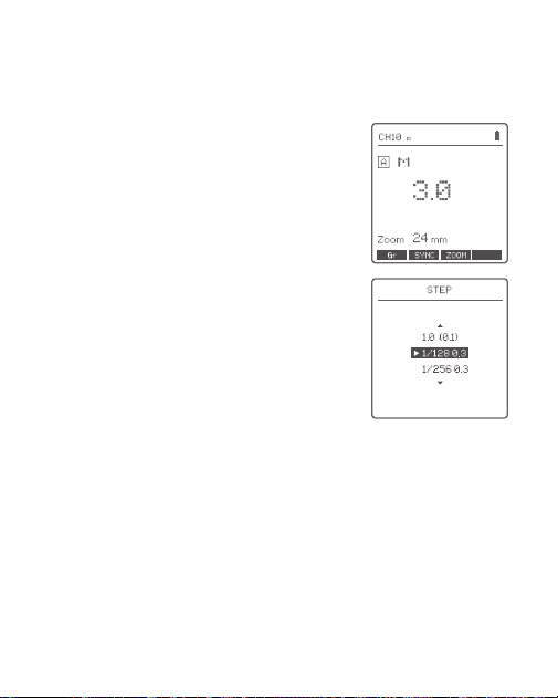
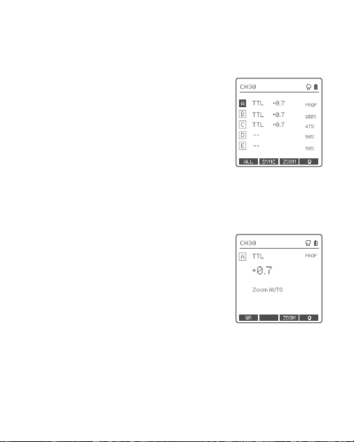
1. Press the group button to choose the group,
turn the select dial, and the power output value
will change from Min. to 1/1 or from Min. to 10
in 0.1 or 1/3 step increments. Then, press <SET>
Button to exit from this setting.
2. Press Function Button 1 (<ALL> button) to
choose all groups’ power output value, turn the
select dial, and all groups’ power output value will
change from Min to 1/1 or from Min. to 10 in 0.1
or 1/3 step increments. Press Function Button 1
(<ALL> button) again to conrm the setting.
44
Single-group displays in the M mode
1. Turn the select dial and the group’s power
output value will change from Min to 1/1 or from
Min. to 10 in 0.1 or 1/3 step increments.
Note: M means manual flash mode.
Note: Min. refers to the minimum value that can be set in M
or Multi mode. The minimum value can be set to 1/128 0.3,
1/256 0.3, 1/512 0.3, 1/128 0.1, 1/256 0.1, 1/512 0.1, 3.0
(0.1), 2.0 (0.1) and 1.0 (0.1) according to MENU-STEP.
45
Flash Exposure Compensation Settings
Multi-group displays in the TTL mode
Single-group displays in the TTL mode
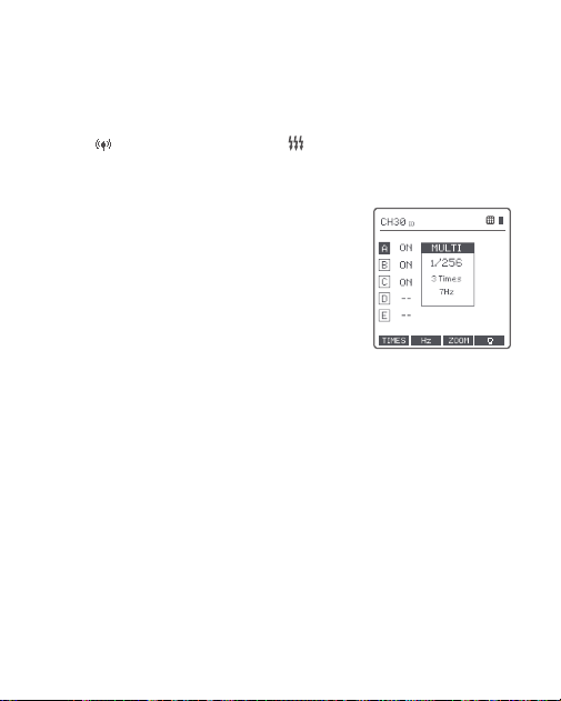
1. Press the group button to choose the group,
turn the select dial, and the FEC value will change
from -3 to 3 in 0.3 step increments. Press the
<SET> button to conrm the setting.
2. Press Function Button 1 (<ALL> button) to
choose all groups’ FEC values, turn the select
dial, and all groups’ FEC values will change from
-3 to 3 in 0.3 step increments. Press Function
Button 1 (<ALL> button) again to conrm the
setting.
1. Turn the select dial and the group’s FEC value
will change from -3 to 3 in 0.3 step increments.
Note: TTL means auto flash mode, FEC means flash
exposure compensation.
SYNC
46
Multi Flash Settings (Output Value, Times and
Frequency)
Conditions for setting the multi flash parameters: 5 (A-E) should be selected
in the <
> WIRELESS-GROUPS, and < > multi flash should be turned on.
When displaying multiple groups, short press the <MODE·LOCK> button to
enter multi flash setting interface.
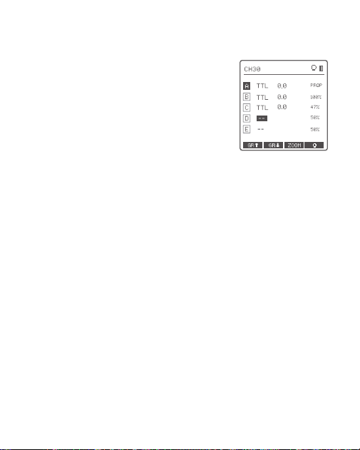
1. In the multi flash (TTL and M icons are not
displayed).
2. The three lines are separately displayed as
power output value (Min. ~ 1/4 or Min. ~ 8.0),
Times (flash times) and Hz (flash frequency).
3. Turn the select dial to change the power
output value from Min. to 1/4 or from Min. to 8.0
in integer steps.
4. Short press the function button 1 (TIMES
button) can change flash times. Turn the select
dial to change the setting value (1-100).
5. Short press the function button 2 (HZ button)
can change flash frequency. Turn the select dial
to change the setting value (1-199).
6. Until any value or three values are set, short
press the <MODE·LOCK> button to exit the
setting status.
Note: As flash times are restricted by flash output value
and flash frequency, the flash times cannot surpass the
upper value that permitted by the system. The times that
transported to the receiver end are real flash time, which is
also related to the camera’s shutter setting.
47
Modeling Lamp Settings
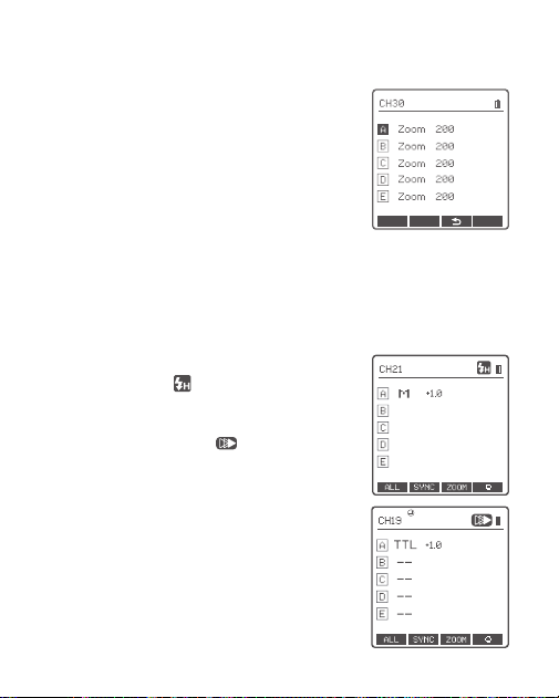
1. When displaying multiple groups, press the
function button 4 button to control the ON/OFF
of the modeling lamp.
2. Press the group button to choose the group
when displaying multiple groups and the
modeling lamp master control is turned on, press
the function button 4 button to control the status
of the modeling lamp: OFF (--), Percentage value
(10
%
-100
%
) or PROP (auto mode, changes
with the flash brightness).
3. When the modeling lamp is in the percentage
value status, long press the function button 4 to
enter the modeling lamp brightness value setting
interface, and turn the select dial to select the
desired modeling lamp percentage value.
4. When displaying single group, it is the same
as the above-mentioned multiple groups display
operation.
48
ZOOM Value Settings
Shutter Sync Settings
FT433 C
Short press the function button 3 and the ZOOM
value will be displayed on the LCD panel. Choose
the group and turn the select dial, and the ZOOM
value will change from AUTO/24 to 200. Choose
the desired value and press the function button 3
again to back to the main menu.
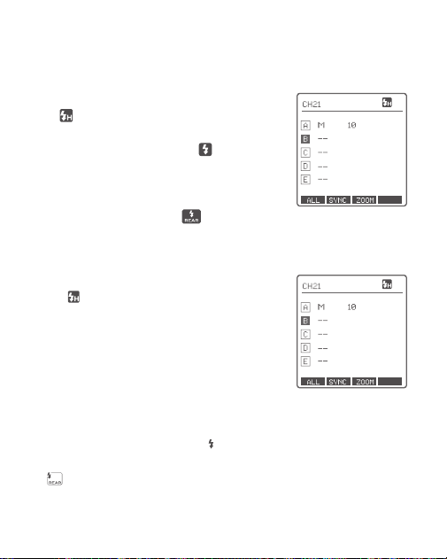
1. High-speed sync: press the function button
under <SYNC> and <
> is displayed on the
LCD panel.
2. Second-curtain sync: press the function
button under <SYNC> and <
> is displayed on
the LCD panel.
Note: Set the WIRELESS-GROUPS to 16 groups (0-F), the
zoom value is unadjustable in both multi-group displays
and single-group displays.
49
FT433 S
FT433 N
1. High-speed sync: press the <SYNC> button
and
is displayed on the LCD panel. Press the
MENU or shortcut Fn on Sony camera to enter
Flash Mode and choose Fill-flash
. Then, set
the camera shutter.
2. Second-curtain sync: press the MENU or
shortcut Fn on Sony camera to enter Flash
Mode and choose REAR flash
. Then, set the
camera shutter.
1. High-speed sync: press the <SYNC> button
and <
> is displayed on the LCD panel. Set
the shutter sync speed to 1/320s (auto FP) or
1/250s (auto FP) in Nikon camera setting. Turn
the camera dial, and the shutter speed can be
set to or more than 1/250s. Check the shutter
speed through the camera viewnder to conrm
whether the FP high-speed function is used. If
the shutter speed is or over 1/250s, it means the
high-speed is booted up.
2. Second-curtain sync: press the <
> on Nikon
camera, and turn the main command dial until
<
> is displayed on the panel. Then, set the
camera shutter.
50
Buzz Settings
PC Socket Settings
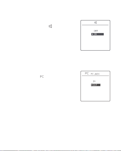
Press the < MENU > button to enter the C. Fn
menu, turn the select dial to <
>, press the
< SET > button to enter and turn the select dial to
select ON/OFF turned on or off. Then press the
< MENU > Button return to the main menu.
Press the <MENU> button to enter C.Fn menu,
turn the select dial to <
>, and press the <SET>
button to enter PC socket setting to choose IN or
OUT. Press the <MENU> button again to back to
the main menu.
When choosing ON, the beeper is turned on.
When choosing OFF, the beeper is turned off.
When choosing IN, the camera will trigger the
flash trigger.
When choosing OUT, the flash trigger will trigger
the flash.
51
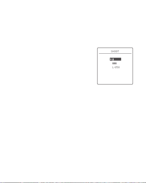
Press the < MENU > Button to enter the C.Fn menu and turn the select dial
to select <SHOOT>, then short press the <SET> button and turn select dial to
select one-shoot/multi-shoots/L-858, after that press <MENU> button return
to the main menu.
SHOOT Function Settings
One-shoot: When shooting, choose one-shoot.
In the M and Multi mode, the transmitter unit
only sends triggering signals to the receiver unit,
which is suitable for one person photography for
the advantage of power saving.
Multi-shoots: When shooting, choose multi-
shoots, and the transmitter unit will send
parameters and triggering signals to the
receiver unit, which is suitable for multi person
photography. However, this function consumes
power quickly.
L-858: The flash parameters can be adjusted
directly on Sekonic L-858 light meter when
collocating with it, and the transmitter only
transmits SYNC signal. The main interface will
only display L-858 when it's turned on, all the
parameters are unavailable to adjust since only
the flash triggering function is available.
52
Bluetooth Settings
APP Downloading
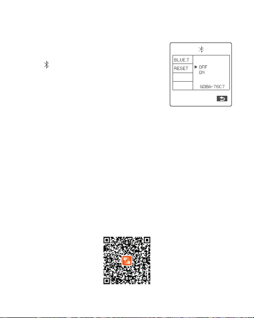
Bluetooth Switch: Short press the MENU button
to enter the C.Fn menu, turn the select dial to
select <
>, then short press the SET button
to enter the Bluetooth setting interface, choose
BLUE.T.E then turn the select dial to OFF (turn off
Bluetooth) or ON (turn on Bluetooth), press the
SET button to conrm the setting, the Bluetooth
MAC code is displayed in the bottom right corner.
Bluetooth Reset: In Bluetooth settings interface,
turn the select dial to turn select dial to choose
“RESET” and short press the SET button to
CANCEL (cancel the reset) or RESET (conrm
to reset), press the SET button to conrm the
setting.
Scan the following QR code to download “Godox Flash” app. (available for
both Android and iOS systems)

53
1. Set the flash trigger: Enter the menu to turn on the Bluetooth, the Bluetooth
MAC code is displayed in the bottom right corner.
2. Set the app: Select <
> connection in the app, enter the Bluetooth MAC
code to connect to the flash trigger, enter the password (initial password
000000) to pair, return to the homepage after successfully connected.
3. The main interface will display < > after turning on the Bluetooth function.
4. Set the channel and ID of receiving flash to the same of the flash trigger, the
parameters of the receiving flash then can be adjusted in the app as follows.
Note: the APP can be used directly on the rstly installed device (smartphone or tablet). When
changing to other mobile device, the light shall be reset before the normal usage of APP.
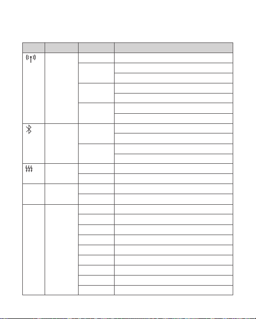
54
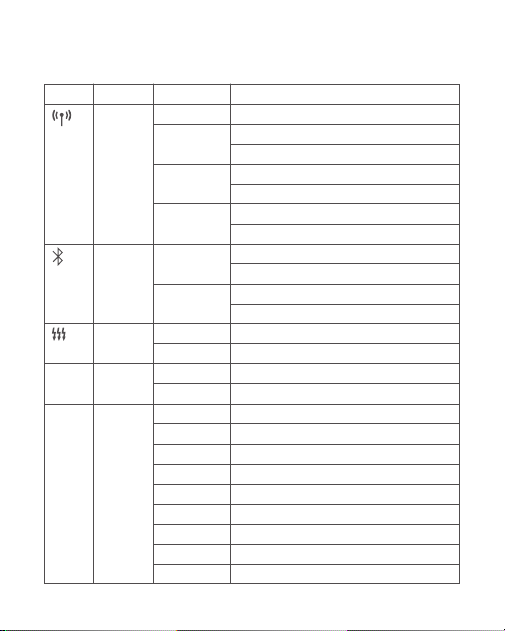
MENU: Setting Custom Functions
Options
CH
ID
DIST
GROUPS
BLUE.T.
RESET
ON
OFF
OFF
0.1ms-9.9ms
1/128 0.3
1/256 0.3
1/512 0.3
1/128 0.1
1/256 0.1
1/512 0.1
3.0
(
0.1
)
2.0
(
0.1
)
1.0
(
0.1
)
Functions
Wireless
Bluetooth
Multi flash
HSS delay
Power
output value
Icons
DELAY
STEP
Settings and Descriptions
32
:
1-32
OFF
:
off
1-99
:
optional from 01-99
1-100m:1-100m triggering
0-10m:0-10m triggering
5(A-E)
:
5 groups
16(0-F):16 groups
0FF: off
ON: on
CANCEL: cancel
RESET: Bluetooth reset
Turn on multi flash
Turn off multi flash
Turn off HSS delay
HSS delay range
The minimum output is 1/128 (change in 1/3 step)
The minimum output is 1/256 (change in 1/3 step)
The minimum output is 1/512 (change in 1/3 step)
The minimum output is 1/128 (change in 0.1 step)
The minimum output is 1/256 (change in 0.1 step)
The minimum output is 1/512 (change in 0.1 step)
The minimum output is 3.0 (change in 0.1 step)
The minimum output is 2.0 (change in 0.1 step)
The minimum output is 1.0 (change in 0.1 step)
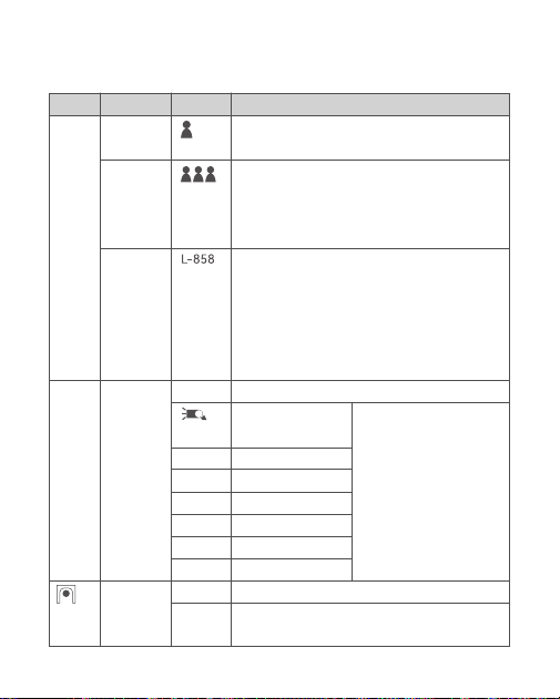
55
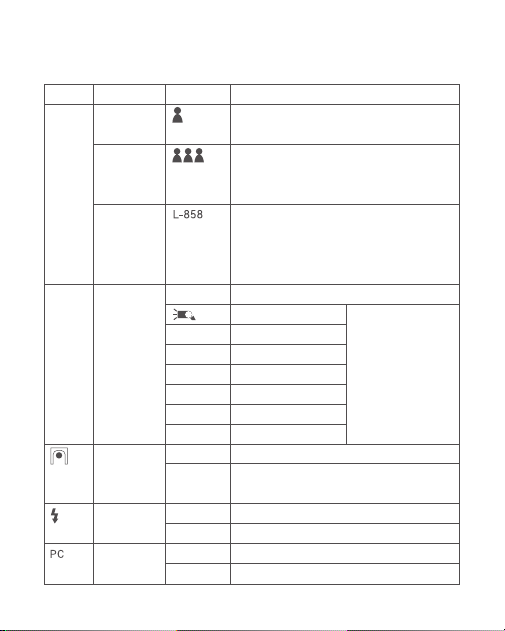
Options
OFF
100j
200j
300j
360j400j
600j
1200j
OFF
ON
Functions
One-shoot
Multi-
shoots
L-858
TCM
transform
function
Legacy hot
shoe
Icons
SHOOT
TCM
Settings and Descriptions
Only send triggering signals in the M & Multi mode
when camera is shooting
Send parameters and triggering signal when camera
is shooting (suitable for multi person photography).
Do not use multi -shoots function when collocating
with X1R-C.
The flash parameters can be adjusted directly on
Sekonic L-858 light meter when collocating with it,
and the transmitter only transmits SYNC signal. The
main interface will only display L-858 when it's turned
on, all the parameters are unavailable to adjust since
only the flash triggering function is available.
Turn off TCM transform function
TT685II/V860III series
AD100Pro
AD200
AD300Pro
AD400Pro
AD600
、
AD600Pro
AD1200Pro
Turn off legacy hot shoe
Turn on legacy hot shoe, TTL flash, HSS function and
multi flash are unaviable.
Transform the TTL shooting
value into the output value
in the M mode. The main
light mode shall prevail in
mixed use. Short press the
<MODE·LOCK> button can
realize TCM transform when
this function is switched on.
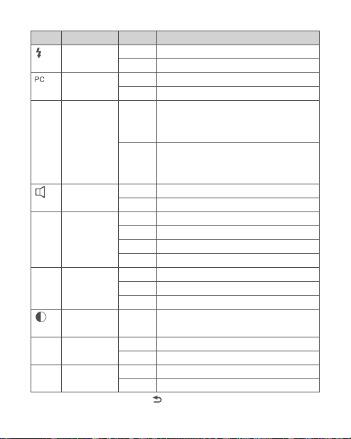
56
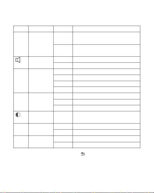
Options
TRIGGER
SHUTTER
IN
OUT
MILC
DSLR
OFF
ON
60sec
30min
60min
OFF
12sec
OFF
ON
-3 to +3
SAVE
LOAD
CANCEL
CLEAR
Note: Short press the <
> function button 4 to return to the previous setting.
Functions
TEST button
PC socket
AF Assist Beam
Beeper
Sleep
Backlighting
LCD contrast
ratio
Preset
Clear function
Icons
AF
(FT433 S)
Settings and Descriptions
Trigger testing
Shutter testing
In port, enable camera to trigger the flash trigger
Out port, enable flash trigger to trigger the flash
When using a mirrorless camera, the AF assist
beam will automatically lighten on only in MILC
(AF Assist Beam is switched on).
When using a DSLR camera, the AF assist
beam will automatically lighten on only
in DSLR (AF Assist Beam is switched on)
Turn off beeper
Turn off beeper
Enter sleep mode after 60 seconds of idle use
Enter sleep mode after 30 minutes of idle use
Enter sleep mode after 60 minutes of idle use
Turn off sleep mode
LCD panel backlight off in 12 seconds
LCD panel backlight always off
LCD panel backlight always lighting
The contrast ration can be set as integral number
from -3 to +3
Save
:
1-5
Import
:
1-5
Cancel
Clear data from menu
Z
Z
Z
LIGHT
USER
CLEAR

57
Note: The range of support functions: the functions that are both owned by FT433 and flash.
Compatible Flash Models
Transmitter
FT433
Receiver
FR433
NoteFlash models
AD200ProII, AD600ProII, AD600BMII
58
1. This table only lists the tested camera models, not all Nikon series cameras.
For the compatibility of other camera models, a self-test is recommended.
2. Rights to modify this table are retained.
Compatible Camera Models
FT433 C can be used on the following Canon series camera models:
FT433 N can be used on the following Nikon series camera models:
FT433 S can be used on the following Sony series camera models:
1. This table only lists the tested camera models, not all Canon series cameras.
For the compatibility of other camera models, a self-test is recommended.
2. The main flashes of certain EOS R series cameras are abnormally
overexposed during TTL high-speed sync flash.
3. Rights to modify this table are retained.
1. This table only lists the tested camera models, not all Sony series cameras.
For the compatibility of other camera models, a self-test is recommended.
2. Rights to modify this table are retained.
5D
Ⅲ
, 5D
Ⅳ
, 60D, 70D, 80D, 1DX, 1DX2, 850D, 760D, 5D
Ⅱ
, 7D
Ⅱ
, 6D
Ⅱ
, 6D, 800D, 90D, 600D,
7D, 3000D, 1500D, 200D
Ⅱ
, M5, M3, M6
Ⅱ
, EOS RP, EOS R, R5, R6
Ⅱ
, R7
D5, D4, D60, D70S, D90, D100, D200, D300S, D300, D500, D610, D700, D750, D800, D810
D3100, D3200, D3300, D5000, D5100, D5200, D5300, D7000, D710, Z6, Z6II, Z7II, D780, Zfc
a77 II, a77, a99, ILCE-6000L, a9, A7R, A7RIII, a350, DSC-RX10, A7IV, A7C, A7M4
59
Technical Data
Transmitter
Model
Compatible cameras
Sync Triggering
Power supply
TTL auto flash
Manual flash
Multi flash
High-speed sync
Second- curtain sync
Flash exposure compensation
Flash exposure lock
Focus assist
Modeling lamp flash
Beeper
Wireless shutter
ZOOM setting
TCM function
Firmware upgrade
Memory function
Display
FT433 S
Sony cameras
FT433 N
Nikon cameras
FT433 C
Canon cameras
Support for the cameras that have PC sync socket
2*AA batteries (sold separately)
√
√
√
√
√ (FT433 S and FT433 N need to be set on the cameras)
±3EV (exposure value), adjustable in 1/3 EV increment
Yes
Yes (this function needs to be available on cameras)
Control the modeling lamp flash by flash trigger
(unavailable on FT433 S)
Control the Beeper by flash trigger
The receiver end can control the camera shooting
through the 2.5mm sync cord jack
AUTO/24-200mm
Transform the TTL shooting value into the output value
in the M mode
Upgrade through the USB-C port
Settings will be stored 2 seconds after last operation
and recover after a restart
Large LCD panel, backlighting ON or OFF
60
Receiver
The laser module information is as follows
Specications and data may subject to changes without notice.
Transmission range (approx.)
Built-in wireless
Modulation mode
Channel
Wireless ID
Group
Dimension
Net Weight (without battery)
Model
Dimension
Net Weight
Maximum output power
Emitted wavelength
Laser class
0-100m
433MHz
GFSK
32
OFF/1-99
5 groups or 16 groups (selectable in the menu)
≈2.44" *3.98" *1.93"
≈97g
FR433
≈0.98" *1.97" mm*0.51""
≈10g
<390μW
650nm±10nm
CLass 1
Restore Factory Settings
Synchronously press the two function buttons in the middle for 2 seconds,
the “RESET” is displayed on the LCD panel with CANCEL and OK options,
choose OK and short press SET button, it will automatically return to the main
interface after the restore factory settings are nished.

61
Firmware Upgrade
Attentions
This flash trigger supports rmware upgrade through the USB-C port. Update
information will be released on our ofcial website.
USB connection line is not included in this product. As the USB port is a
USB-C socket, please use USB-C connection line.
As the rmware upgrade needs the support of Godox G3 V1.1 software,
please download and install the "Godox G3 V1.1 rmware upgrade software"
before upgrading. Then, choose the related rmware le. The latest electronic
version of instruction manual shall prevail due to rmware upgrade.
1. Unable to trigger flash or camera shutter. Make sure batteries are installed
correctly and power switch is turned on. Check if the transmitter and the
receiver are set to the same channel, if the hots hoe mount or connection
cable is well connected, or if the flash triggers are set to the correct mode.
2. Camera shoots but does not focus. Check if the focus mode of the camera
or lens is set to MF. If so, set it to AF.
3. Signal disturbance or shooting interference. Change a different channel on
the device.

62
The Reason & Solution of Not Triggering in Godox
2.4G Wireless
→
To adjust the channel CH setting on the flash trigger (add 10+ channels)
and use the channel which is not disturbed. Or turn off the other 2.4G
equipment in working.
→
Please replace or charge the battery, ensure the flash trigger and the flash
are fully charged.
→ Please update the rmware of the ash trigger refer to the
rmware upgrade instructions.
→
Please downgrade the flash power output. If the flash is in TTL mode,
please try to change it to M mode (a preflash is needed in TTL mode).
→
Please turn on the “close distance wireless mode” on the flash trigger.
FT433 series: Set the Menu-Wireless Setting-DIST to 0-10m.
1. Disturbed by the 2.4G signal in outer environment (e.g. wireless base
station, 2.4G wi router, Bluetooth, etc.)
4. Whether the flash trigger and the receiver end equipment are in the low
battery states or not
5. The flash trigger rmware is an old version
2. Please make sure that whether the flash has nished its recycle or caught
up with the continuous shooting speed or not(the flash ready indicator is
lighten) and the flash is not under the state of over-heat protection or other
abnormal situation.
3. Whether the distance between the flash trigger and the flash is too close
or not (<0.5m).

Warning
Warning
Declaration of Conformity
Operating frequency: 2402MHz – 2480MHz
Maximum EIRP Power: -0.96dBm
Operating frequency: 433MHz
Maximum ERP Power: -7.34dBm
GODOX Photo Equipment Co.,Ltd. hereby declares that this equipment are in
compliance with the essential requirements and other relevant provisions of
Directive 2014/53/EU. In accordance with Article 10(2) and
Article 10(10), this product is allowed to be used in all EU member states.For
more information of DoC, Please click this web link:
https://www.godox.com/eu-declaration-of-conformity/
The device complies with RF specications when the device used at 0mm
from your body.

L’emetteur/recepteur exempt de licence contenu dans le present appareil est
conforme aux CNR d’Innovation, Sciences et Developpement economique
Canada applicables aux appareils radio exempts de licence. L’exploitation est
autorisee aux deux conditions suivantes :
1. L’appareil ne doit pas produire de brouillage;
2. L’appareil doit accepter tout brouillage radioelectrique subi, meme si le
brouillage est susceptible d’en compromettre le fonctionnement.
The device is compliance with RF exposure guidelines, users can obtain
Canadian information on RF exposure nd compliance.The device can be used
in portable exposure condition without restriction.
Le present appareil est conforme Apres examen de ce materiel aux
conformite ou aux limites d’intensite de champ RF, les utilisateurs peuvent sur
l’exposition aux radiofrequences et compliance d’acquerir les informations
correspondantes.
The device contains licence-exempt transmitter(s)/receiver(s) that comply
with Innovation, Science and Economic Development Canada’s licence-
exempt RSS(s).
Operation is subject to the following two conditions:
(1) This device may not cause interference.
(2) This device must accept any interference, including interference that may
cause undesired operation of the device.
IC Warning

FCC Statement
Note:
This device complies with part 15 of the FCC Rules. Operation is subject to
the following two conditions:
(1) This device may not cause harmful interference, and
(2) this device must accept any interference received, including interference
that may cause undesired operation.
Any Changes or modications not expressly approved by the party responsible
for compliance could void the user's authority to operate the equipment.
This equipment has been tested and found to comply with the limits for a
Class B digital device, pursuant to part 15 of the FCC Rules. These limits
are designed to provide reasonable protection against harmful interference
in a residential installation. This equipment generates uses and can radiate
radio frequency energy and, if not installed and used in accordance with
the instructions, may cause harmful interference to radio communications.
However, there is no guarantee that interference will not occur in a particular
installation. If this equipment does cause harmful interference to radio or
television reception, which can be determined by turning the equipment off
and on, the user is encouraged to try to correct the interference by one or
more of the following measures:
-Reorient or relocate the receiving antenna.
-Increase the separation between the equipment and receiver.
-Connect the equipment into an outlet on a circuit different from that to which
the receiver is connected.
-Consult the dealer or an experienced radio/TV technician for help.
The device has been evaluated to meet general RF exposure requirement.
The device can be used in portable exposure condition without restriction.
产品保修
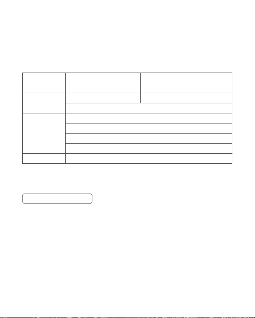
尊敬的用户,本保修卡是申请保修服务的重要凭证,请您配合销售商填写并妥
善保管,谢谢!
产品信息
用户信息
销售商信息
备注
型号
姓名
通信地址
名称
联系电话
通信地址
销售日期
产品条码
联系电话
注:此表应由销售商盖章确认。
本文件适用于相关《产品保修信息》( 见后面说明 ) 所列产品,其他非属此范
围的产品或部件 ( 如促销品、赠品及其他出厂后附加的部件等 ) 不在此保修承
诺内。
产品信息
产品及部件的相应保修期按相关的《产品保修信息》执行。保修期自产品首次
购买日起算,购买日以购买产品时保修卡登记日期为准。
保修期

您可直接与产品销售商或授权服务机构联系,也可拨打神牛产品售后服务电话,
与我们联系,由我们的服务人员为您安排服务。申请保修时,您应提供有效的
保修卡作为保修凭证,方可获得保修。如您不能提供有效的保修卡,则在我们
确认产品或部件属于保修范围的情况下,也可以为您提供保修,但这不作为我
们的义务。
如何获得保修服务
如产品存在下列情况,本文件项下的保证和服务将不适用 : ①产品或部件超过
相应保修期;②错误或不适当使用、维护或保管导致的故障或损坏,如:不
当搬运;非按产品合理预期用途使用;不当插拨外接设备;跌落或外力挤压;
接触或暴露于不适当温度、溶剂、酸碱、水浸或潮湿环境;③由非神牛授权
机构或人员安装、修理、更改、添加或拆卸造成的故障或损坏;④产品或部件
原有识别信息被修改变更或除去;⑤无有效保修卡;⑥使用非合法授权、非标
准或非公开发行的软件造成的故障或损坏;⑦因不可抗力或意外事件造成的
故障或损坏;⑧其他非因产品本身质量问题导致的故障或损坏。遇上述情况,
您应向相关责任方寻求解决,神牛对此不承担任何责任。因非在保修期或保修
范围内的部件、附件或软件导致产品不能正常使用的,不是保修范围内的故障。
产品使用过程中正常的脱色,磨损和消耗,不是保修范围内的故障。
不适用保修情況
产品类别
部件
其他
选件名称
电路板
电池
充电器等带电性能的部件。
如闪光管、造型灯泡、外壳、
保护罩、锁紧装置、包装等。
保修期(月)
12
3
12
无
神牛产品售后服务电话
0755-29609320-8062
产品保修和服务支持信息
产品的保修期和服务类型按以下《产品保修信息》执行:
保修服务类型
客户送修
客户送修
客户送修
无保修
Warranty
Dear customers, as this warranty card is an important certicate to apply for
our maintenance service, please ll in the following form in coordination with
the seller and safe-keep it. Thank you!
Note: This form shall be sealed by the seller.
Product
Information
Customer
Information
Seller
Information
Note
Model
Name
Address
Name
Contact Number
Address
Date of Sale
Product Code Number
Contact Number
Applicable ProductsThe document applies to the products listed on the
Product Maintenance lnformation (see below for further information). Other
products or accessories (e.g. promotional items,giveaways and additional
accessories attached,etc.) are not included in this warranty scope.
Applicable Products

The warranty period of products and accessories isimplemented according
to the relevant Product Maintenance Information. The warranty period is
calculated from the day(purchase date) when the product is bought for the
rst time,And the purchase date is considered as the date registered onthe
warranty card when buying the product.
Warranty Period
If maintenance service is needed, you can directly contact the product
distributor or authorized service institutions. You can also contact the
Godox after-sale service call and we will offer you service. When applying for
maintenance service, you should provide valid warranty card. If you cannot
provide valid warranty card, we may offer you maintenance service once
conrmed that the product or accessory is involved in the maintenance scope,
but that shall not be considered as our obligation.
How to Get the Maintenance Service

The guarantee and service offered by this document are not applicable in
the following cases:
①
The product or accessory has expired its warranty
period;
②
Breakage or damage caused by inappropriate usage, maintenance
or preservation, such as improper packing, improper usage, improper
plugging in/out external equipment, falling off or squeezing by external force,
contacting or exposing to the improper temperature, solvent, acid, base,
flooding and damp environments, etc;
③
Breakage or damage caused by
non-authorized institution or staff in the process of installation, maintenance,
alternation, addition and detachment;
④
The original identifying information
of product or accessory is modified, alternated, or removed;
⑤
No valid
warranty card;
⑥
Breakage or damage caused by using illegally authorized,
nonstandard or non-public released software;
⑦
Breakage or damage caused
by force majeure or accident;
⑧
Breakage or damage that could not be
attributed to the product itself. Once met these situations above, you should
seek solutions from the related responsible parties and Godox assumes no
responsibility. The damage caused by parts, accessories and software that
beyond the warranty period or scope is not included in our maintenance
scope. The normal discoloration, abrasion and consumption are not the
breakage within the maintenance scope.
Inapplicable Cases
Godox After-sale Service Call +86-755-29609320(8062)
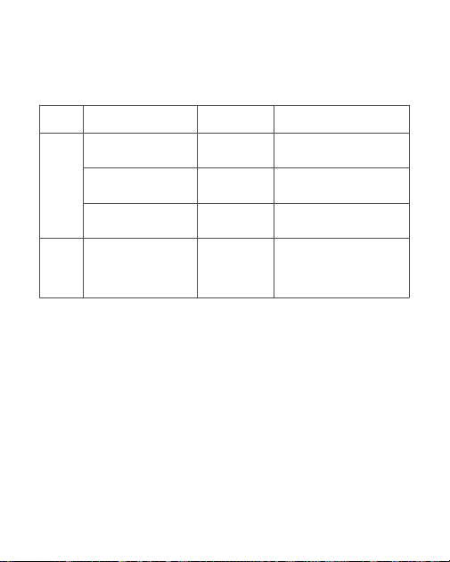
Maintenance and Service Support Information
The warranty period and service types of products are implemented according to the
following Product Maintenance Information:
Product
Type
Parts
Other
Items
Flash tube, modeling
lamp, lamp body, lamp
cover, locking device,
package, etc.
Electrical parts
e.g.battery charger, etc.
Battery
Circuit board
Name
Maintenance
Period(month)
3
12
3
No
Customer sends the product
to designated site
Customer sends the product
to designated site
Customer sends the product
to designated site
Without warranty
Warranty
Service Type