
EN
L2 Switch
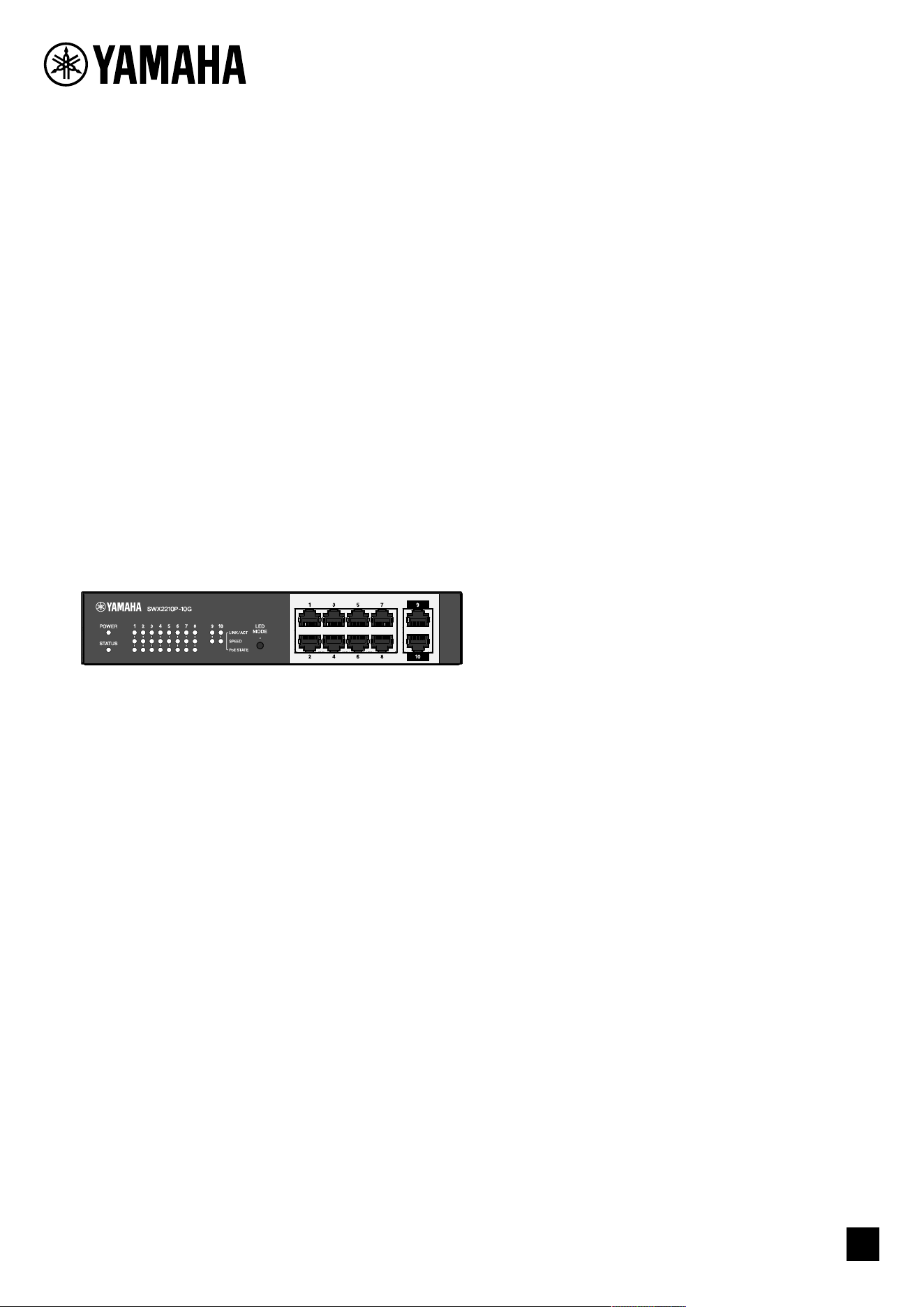
SWX2210P-10G
Getting Started Guide

Contents
1. Introduction . . . . . . . . . . . . . . . . . . . . . . . . . . . . . . . . . . . . . . . . . . . . . . . . . . . . . . . . . . . . . . . . . . . . . . . . . Ê3
1.1. Product features. . . . . . . . . . . . . . . . . . . . . . . . . . . . . . . . . . . . . . . . . . . . . . . . . . . . . . . . . . . . . . . . . Ê3
1.2. Included items . . . . . . . . . . . . . . . . . . . . . . . . . . . . . . . . . . . . . . . . . . . . . . . . . . . . . . . . . . . . . . . . . . . Ê3
1.3. Separately sold items . . . . . . . . . . . . . . . . . . . . . . . . . . . . . . . . . . . . . . . . . . . . . . . . . . . . . . . . . . . . . Ê3
1.4. Related software and documents . . . . . . . . . . . . . . . . . . . . . . . . . . . . . . . . . . . . . . . . . . . . . . . . . . . Ê3
1.5. Conventions used in this guide. . . . . . . . . . . . . . . . . . . . . . . . . . . . . . . . . . . . . . . . . . . . . . . . . . . . . . Ê4
2. Controls and connectors. . . . . . . . . . . . . . . . . . . . . . . . . . . . . . . . . . . . . . . . . . . . . . . . . . . . . . . . . . . . . . . Ê5
2.1. Front panel . . . . . . . . . . . . . . . . . . . . . . . . . . . . . . . . . . . . . . . . . . . . . . . . . . . . . . . . . . . . . . . . . . . . . Ê5
2.2. Bottom panel . . . . . . . . . . . . . . . . . . . . . . . . . . . . . . . . . . . . . . . . . . . . . . . . . . . . . . . . . . . . . . . . . . . . Ê7
2.3. Rear panel . . . . . . . . . . . . . . . . . . . . . . . . . . . . . . . . . . . . . . . . . . . . . . . . . . . . . . . . . . . . . . . . . . . . . . Ê7
2.4. Side panel. . . . . . . . . . . . . . . . . . . . . . . . . . . . . . . . . . . . . . . . . . . . . . . . . . . . . . . . . . . . . . . . . . . . . . . Ê8
2.5. Top panel . . . . . . . . . . . . . . . . . . . . . . . . . . . . . . . . . . . . . . . . . . . . . . . . . . . . . . . . . . . . . . . . . . . . . . . Ê8
3. Installation. . . . . . . . . . . . . . . . . . . . . . . . . . . . . . . . . . . . . . . . . . . . . . . . . . . . . . . . . . . . . . . . . . . . . . . . . . Ê9
3.1. Placing the unit on a level surface. . . . . . . . . . . . . . . . . . . . . . . . . . . . . . . . . . . . . . . . . . . . . . . . . . . Ê9
3.2. Installing in a 19-inch rack. . . . . . . . . . . . . . . . . . . . . . . . . . . . . . . . . . . . . . . . . . . . . . . . . . . . . . . . Ê10
3.3. Installing onto a wall . . . . . . . . . . . . . . . . . . . . . . . . . . . . . . . . . . . . . . . . . . . . . . . . . . . . . . . . . . . . Ê12
4. Connections . . . . . . . . . . . . . . . . . . . . . . . . . . . . . . . . . . . . . . . . . . . . . . . . . . . . . . . . . . . . . . . . . . . . . . . . Ê15
4.1. Connecting the power cord . . . . . . . . . . . . . . . . . . . . . . . . . . . . . . . . . . . . . . . . . . . . . . . . . . . . . . . Ê15
4.2. Connecting to a network device or computer. . . . . . . . . . . . . . . . . . . . . . . . . . . . . . . . . . . . . . . . . Ê16
4.3. Connecting PoE-powered devices . . . . . . . . . . . . . . . . . . . . . . . . . . . . . . . . . . . . . . . . . . . . . . . . . . Ê16
5. Settings . . . . . . . . . . . . . . . . . . . . . . . . . . . . . . . . . . . . . . . . . . . . . . . . . . . . . . . . . . . . . . . . . . . . . . . . . . . Ê17
5.1. Making settings using the Web GUI. . . . . . . . . . . . . . . . . . . . . . . . . . . . . . . . . . . . . . . . . . . . . . . . . Ê17
5.2. Making settings from the command line using Telnet . . . . . . . . . . . . . . . . . . . . . . . . . . . . . . . . . . Ê18
5.3. Restoring this unit’s settings to their factory-set defaults . . . . . . . . . . . . . . . . . . . . . . . . . . . . Ê20
Contents
2 | L2 Switch SWX2210P-10G Getting Started Guide

1. Introduction
1.1. Product features
The smart L2 switch SWX2210P-10G is an L2 PoE switch that is ideal for accommodating PoE-powered
devices in small and medium-sized networks. It supports power supply via IEEE802.3at (PoE+), which
allows for a maximum power supply of 30W per port, and enables easy configuration of ProAV profiles
such as Dante, making it useful as a switch for accommodating ProAV equipment such as PoE-powered
speakers/microphones and cameras.
1.2. Included items
Verify that the following included items are present.
• Read This First: 1 pc.
• Power cords: 2 pcs. (use an appropriate power cord for your regional power supply.)
• Power cord clamp: 1 pc. (used only for the included dedicated power cord)
• Legs (rubber feet): 4 pcs.
1.3. Separately sold items
• Rack Mount Kit RK-SWR
Required when mounting in a 19-inch rack (1U size). For details on installation, refer to “Installing
the unit in a 19-inch rack” in “Installation.”
• Wall Mount Kit WK-SWR
Required for installation on a wall. For details on installation, refer to “Installing onto a wall” in
“Installation.”
Details are provided on the Yamaha website.
https://www.yamahaproaudio.com/
1.4. Related software and documents
The following manuals are prepared according to the intended use of this product.
Read the appropriate manual according to your particular application.
• Read This First (included)
Describes the precautions for using this product. Be sure to read before use.
• Getting Started Guide (this book)
Describes how to install, connect, and set this product and other options.
• Command Reference (website)
Describes the command format for setting up this product and a usage example.
• Technical Data (website)
Describes detailed information about the features of this product.
• Help for “Web Settings Screen”
Describes detailed explanations about each setting item.
The following software is prepared.
• Yamaha LAN Monitor
This is an application used to monitor this unit’s information and the entire network
including all Dante devices on the Dante network, and the user guide for this application.
1. Introduction
L2 Switch SWX2210P-10G Getting Started Guide | 3

The software above can be downloaded from the following website.
https://www.yamahaproaudio.com/
1.5. Conventions used in this guide
• Copying or reproduction of this guide in whole or in part is expressly forbidden without the
written consent of the manufacturer.
• The explanations in this guide are based on current product specifications as of the date of
publication. The latest version of this document can be downloaded from the Yamaha website.
• All illustrations and screens included in this guide are for the purpose of explanation.
• Company names and product names in this guide are abbreviated as follows.
◦ Yamaha L2 Switch SWX2210P-10G: This product
◦ 10BASE-T/100BASE-TX/1000BASE-T cable: LAN cable
• Other company names and product names in this document are the registered trademarks or
trademarks of their respective corporate owners.
◦ Microsoft and Windows are registered trademarks of Microsoft Corporation USA in the USA
and other countries.
• The symbols listed in this guide and their contents are as follows.
Warning: Refers to a situation that poses the risk of death or serious injury to
the user.
Caution: Refers to a situation that poses the risk of injury to the user.
Caution: Refers to information that the user must comply with to avoid product
malfunction, damage, faulty operations or loss of data.
Important: Refers to information that the user must know to properly operate
and use this product.
Note: Refers to information regarding the operation and use of this product.
Read this for your reference.
1. Introduction
4 | L2 Switch SWX2210P-10G Getting Started Guide
2. Controls and connectors
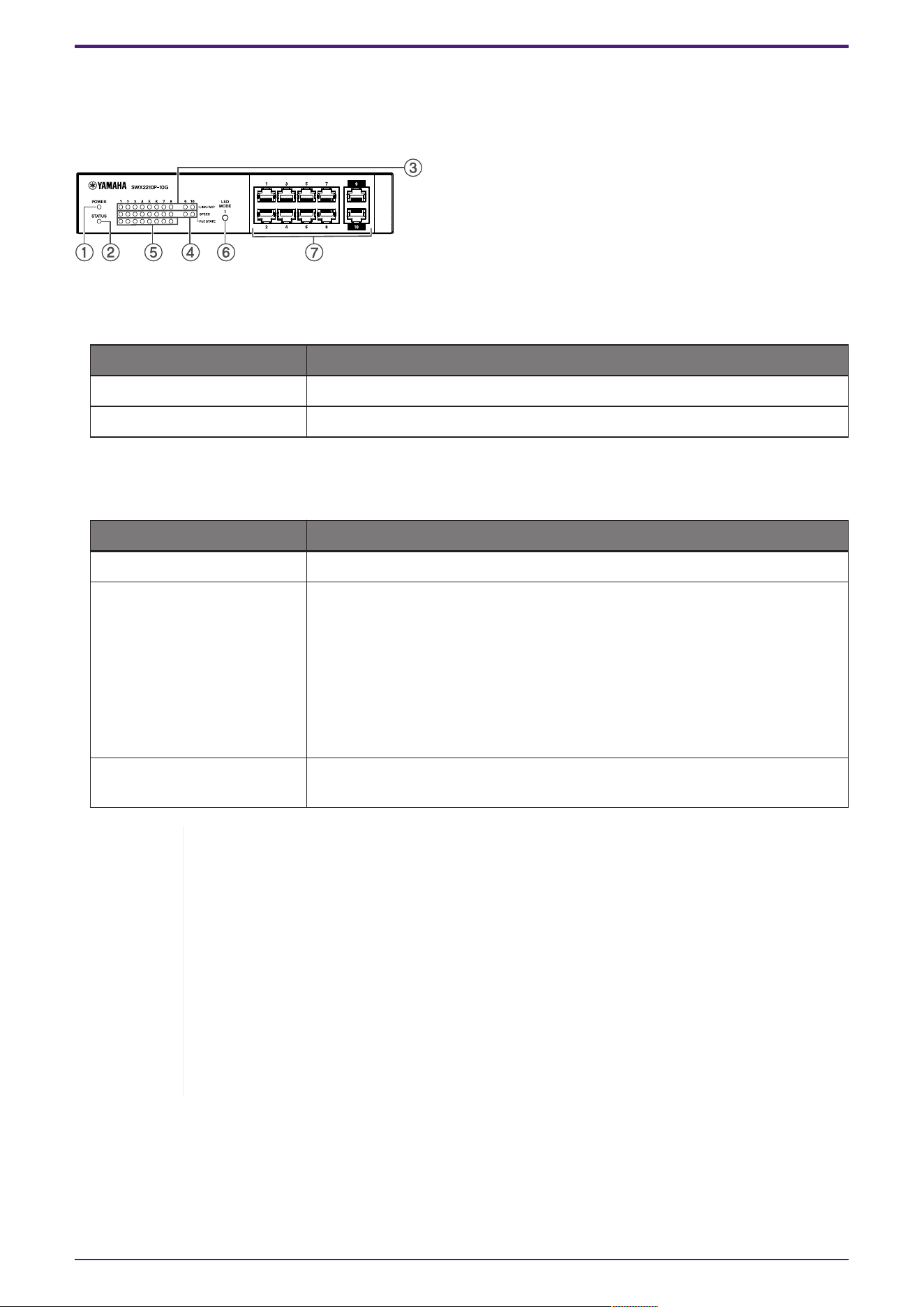
2.1. Front panel
① POWER indicator
Lights when power is provided to the unit.
POWER indicator Status
Unlit Power OFF
Lit (green) Power ON
② STATUS indicator
Indicates the status of this product.
STATUS indicator Product status
Unlit Normal
Lit (orange) One of the following conditions:
• The total PoE power supply exceeds the maximum power supply of
this product.
• Power supply is restricted by the PoE guardband function.
• Overcurrent detected on the PoE port.
• A loop has been detected and the port is in blocking state.
Flashing (orange) Anomalies have been detected in the fan, internal temperature, or PoE
power supply.
Caution: If the STATUS indicator is flashing orange, check the abnormality status
and take appropriate action.
• Fan stopped
Stop using this product immediately and contact the dealer where you
purchased this product to have the unit inspected and/or repaired.
• PoE power supply failure
Stop using this product immediately and contact the dealer where you
purchased this product to have the unit inspected and/or repaired.
• Internal temperature abnormal
Review the environment in which this product is installed, and correctly install
this product so that the internal temperature is at an appropriate level.
You can check for temperature and fan abnormalities using the show environment command.
For more information about commands, refer to the command reference.
For the command reference, refer to the information page for this product on the Yamaha website.
2. Controls and connectors
L2 Switch SWX2210P-10G Getting Started Guide | 5
③ LINK/ACT indicators
Indicate LAN port status.
LINK/ACT indicators LAN port status
Unlit The link is lost (not available) or the indicators have been turned off
with the LED MODE button.
Lit (green) Link is established (available).
Flashing (green) Data is flowing.
Flashing (orange) A loop is detected.
④ SPEED indicators
Indicate the connection speed of the LAN port.
SPEED indicators Connection status
Unlit One of the following conditions:
• Not connected.
• Connected by 10BASE-TX.
• The indicators have been turned off with the LED MODE button.
Lit (orange) Connected by 100BASE-TX.
Lit (green) Connected by 1000BASE-TX.
⑤ PoE STATE indicators
Indicate the power supply status.
PoE STATE indicators Power supply status
Unlit No power is being supplied.
Or the indicators have been turned off with the LED MODE button.
Lit (orange) Power supply has been stopped due to limitations on total power
supply.
Or, the total power supply falls within the guard band range,
suppressing power supply.
Flashing (orange) Power supply has been stopped due to overcurrent detection.
Lit (green) Power is being supplied.
⑥ LED MODE button
This button switches the LINK/ACT, SPEED, and PoE STATE indicators ON or OFF. If the indicators
are on, press and hold the LED MODE button (for more than one second) to turn the indicators off.
If the indicators are off, press and hold the LED MODE button to turn them on.
This is also used to restore the factory default settings. For details, refer to "Restoring the factory
settings with the LED MODE button" in "Settings".
⑦ LAN ports
These are 10BASE-T, 100BASE-TX, and 1000BASE-T Ethernet ports.
Ports 1 to 8 support IEEE 802.3at PoE power supply functionality.
Ports 9 and 10 are uplink ports without power supply functionality.
2. Controls and connectors
6 | L2 Switch SWX2210P-10G Getting Started Guide
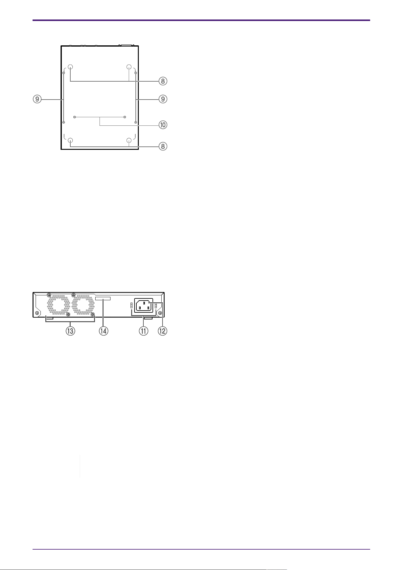
2.2. Bottom panel
⑧ Rubber foot attachment guides
These are the locations where the rubber feet are to be attached when placing the unit on a level
surface. For details on installation, refer to "Placing the unit on a level surface" in "Installation."
⑨ Wall mount accessory attachment holes
These are screw holes for attaching optional wall mount accessory WK-SWR when installing onto a
wall. For details on installation, refer to "Installing onto a wall" in "Installation".
⑩ Rack mount accessory mounting holes
Use these holes to attach an optional rack mount accessory RK-SWR. For details on installation,
refer to "Installing in a 19-inch rack" in "Installation."
2.3. Rear panel
⑪ Power cord clamp attachment holes
The included power cord clamp (C-shaped) can be attached here. For details on installation, refer to
"Connecting the power cord" in "Connections."
⑫ Power supply inlet (three-pin connector, C14 type)
Insert the included power supply cord here. Use an appropriate power cord for your regional power
supply.
⑬ Fan
The fan is used to force out heat generated inside the unit. If an error is detected, the STATUS
indicator on the front panel flashes orange.
Warning: Do not block or place objects near the fan outlet.
Doing so could cause fire or malfunctions.
⑭ Serial number
The product label has the same indication.
2. Controls and connectors
L2 Switch SWX2210P-10G Getting Started Guide | 7
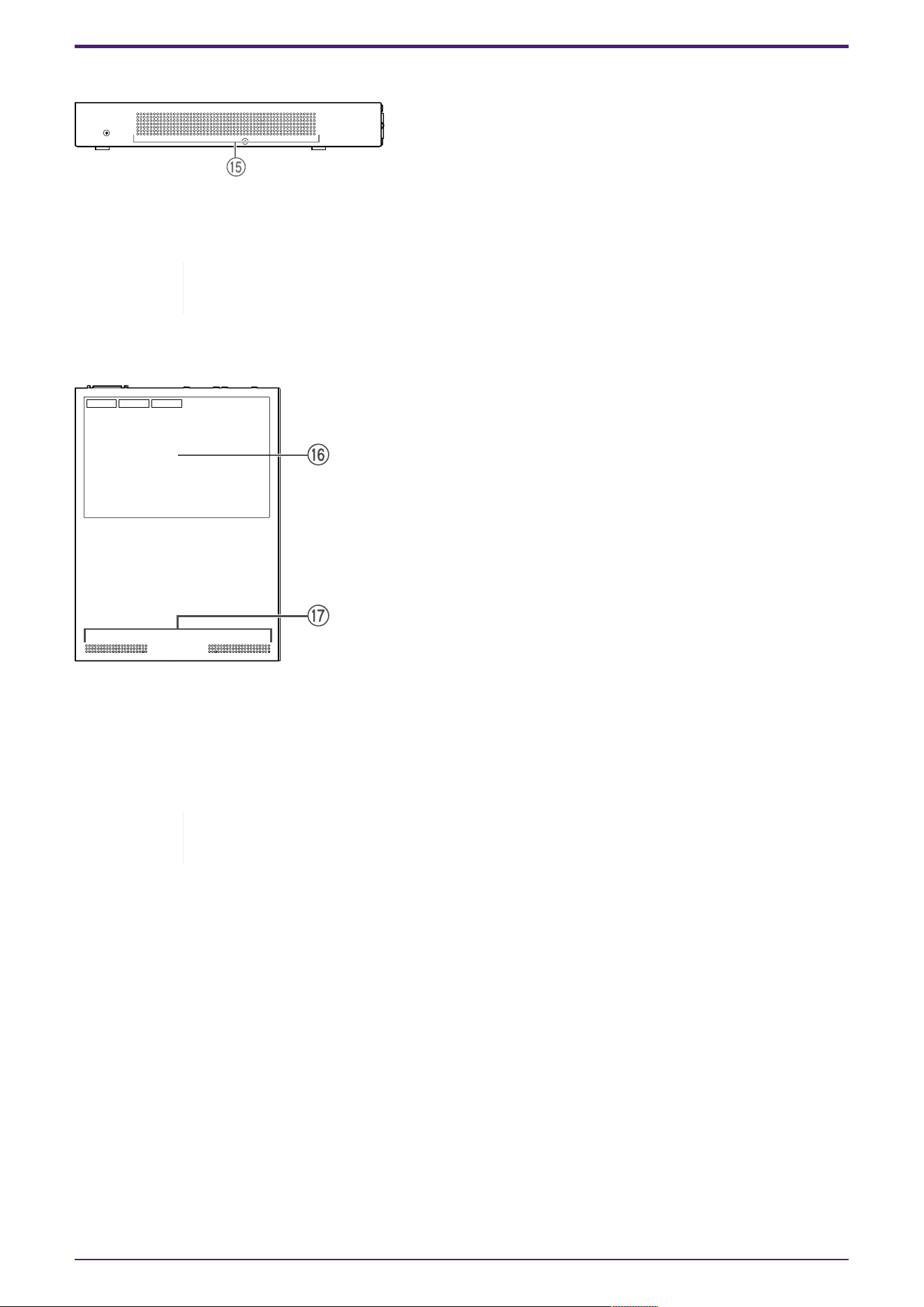
2.4. Side panel
⑮ Cooling vents
The holes in this product are cooling vents by the fan for intake of external air.
Warning: Do not block the cooling vents or place objects near them.
Doing so could cause fire or malfunctions.
2.5. Top panel
⑯ Product label
This lists the model name, serial number, and MAC address etc. of this unit.
⑰ Cooling vents
The holes in this product are cooling vents for intake of external air.
Warning: Do not block the cooling vents or place objects near them.
Doing so could cause fire or malfunctions.
2. Controls and connectors
8 | L2 Switch SWX2210P-10G Getting Started Guide
3. Installation
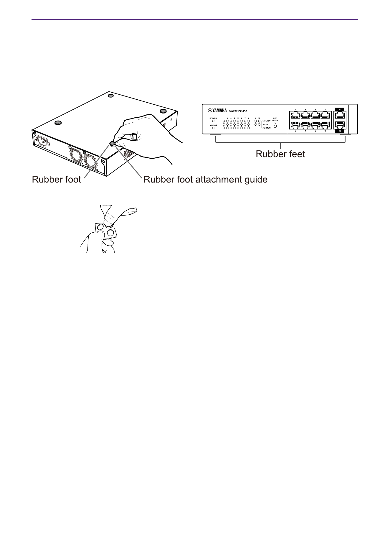
3.1. Placing the unit on a level surface
As shown in the illustration, attach the included rubber feet in the positions of the rubber feet
attachment guides, and place the unit on a level location such as a desk.
Note: Four rubber feet are included in one sheet (illustration below).
3. Installation
L2 Switch SWX2210P-10G Getting Started Guide | 9
3.2. Installing in a 19-inch rack
For installation, use the optional rack mount kit RK-SWR.
[Installation method]
This section explains how to attach the unit in the middle block of a rack mount panel. Even if you plan
to attach the unit in the left or right block, follow the procedure below.
Warning: When attaching or removing this unit, you must disconnect the unit’s power
plug from the power outlet.
Failing to do so could cause electrical shock or malfunctions.
Important: If there are rubber feet attached to the bottom of this product, remove
them before installing the mount panel.
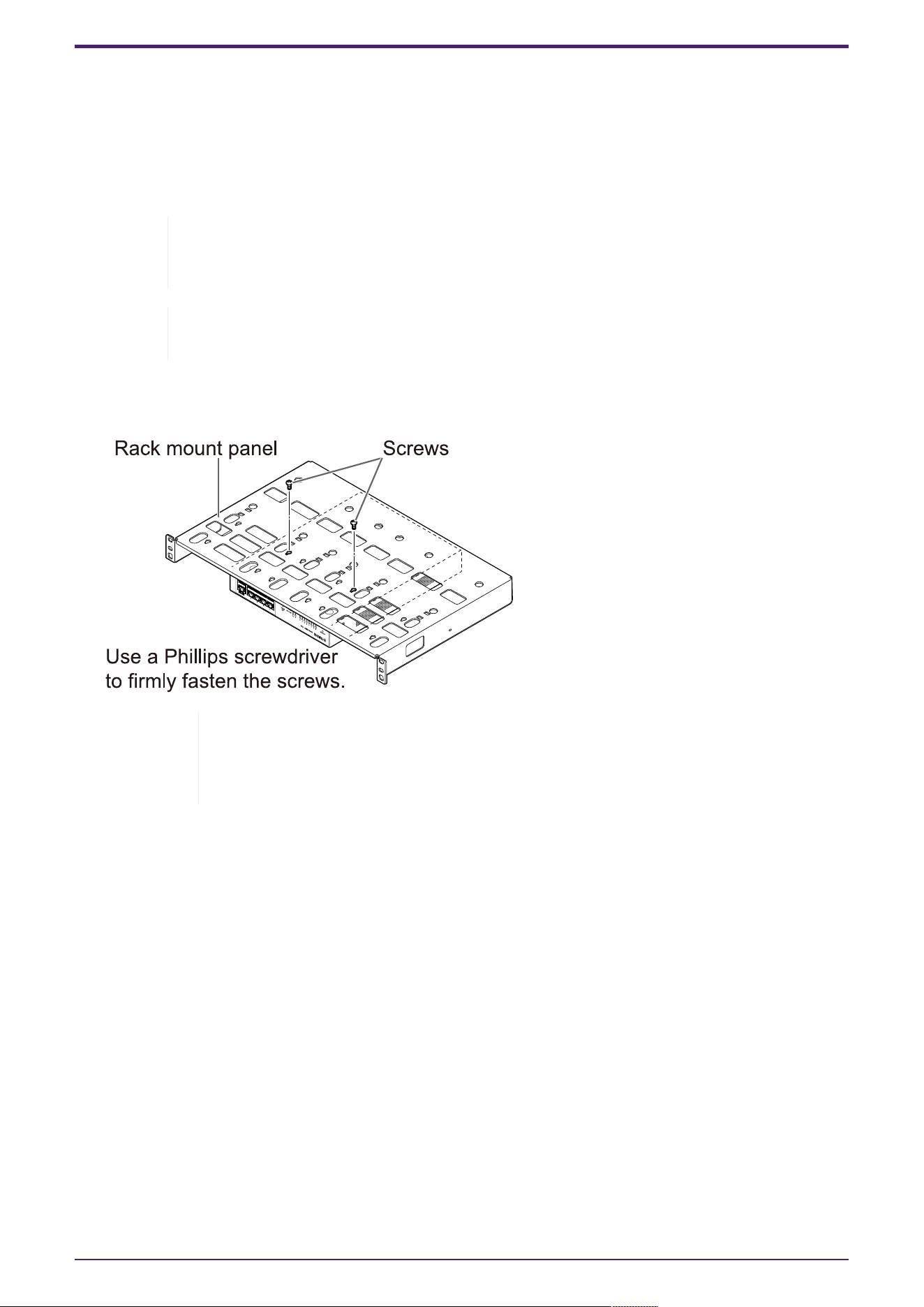
1. Attaching the unit to the rack mount panel
Using the two screws supplied with the rack-mount accessory, attach the rack mount panel to the
bottom panel of the unit.
Warning: When mounting this product to the optional rack mount kit RK-SWR, be
sure to use the specified screws included with the mount kit.
If the unit falls, you may be injured or the unit may become damaged. This could
also cause electric shock or malfunctions.
3. Installation
10 | L2 Switch SWX2210P-10G Getting Started Guide
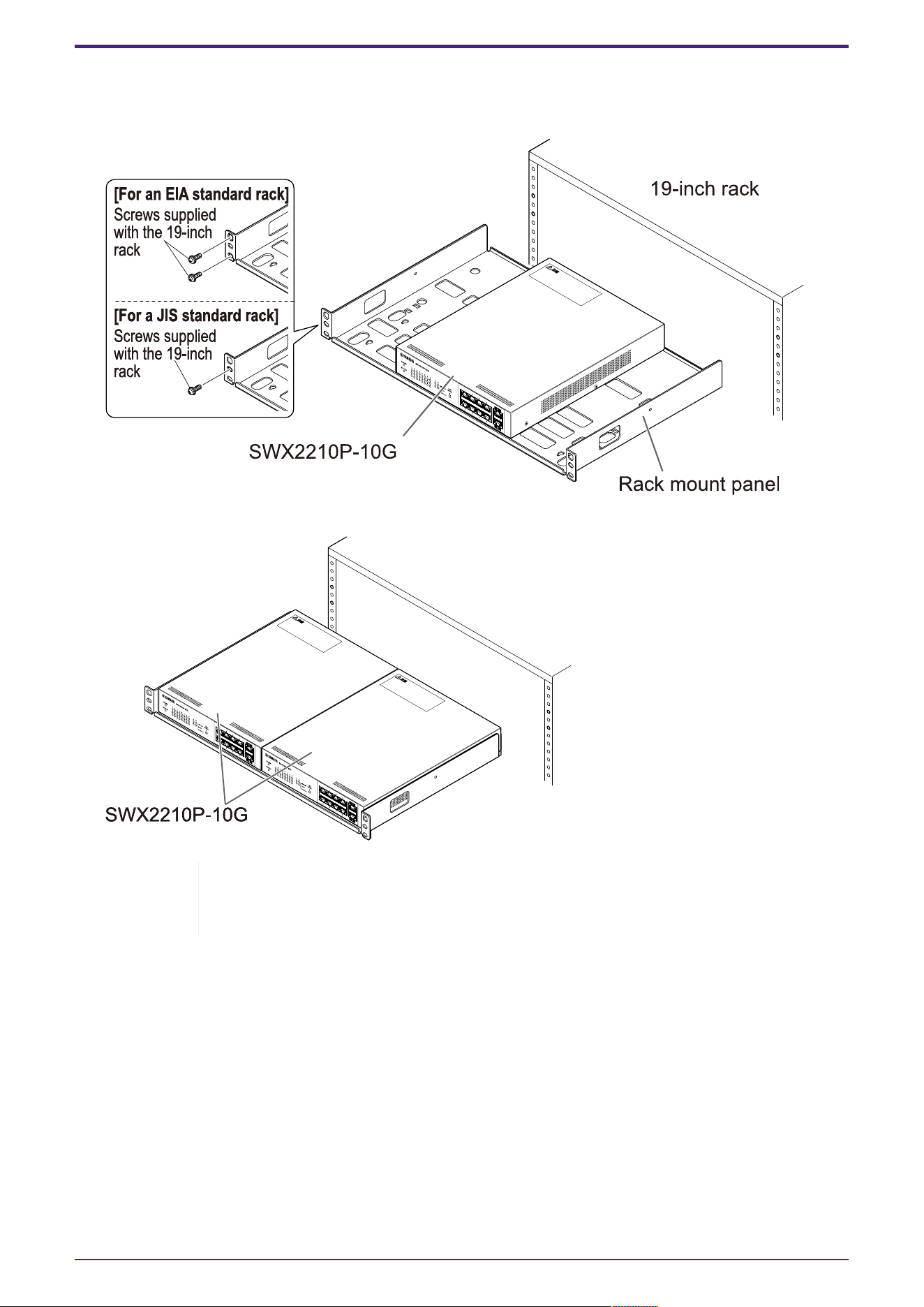
2. Attach the rack mount panel to the 19-inch rack.
Use the mounting screws (four EIA standard screws, two JIS standard screws) provided with the
19-inch rack to mount this product to the 19-inch rack. Firmly tighten the screws so that they will
not loosen.
You can also mount two SWX2210P-10G units as shown in the illustration below.
Warning: Do not block the cooling vents on the top or the sides of this unit, or
the fan outlet on the back.
Doing so could cause fire or malfunctions.
3. Installation
L2 Switch SWX2210P-10G Getting Started Guide | 11
3.3. Installing onto a wall
Installation is done using the optional wall mount kit WK-SWR. For details on installation and
precautions, refer to the "WK-SWR Instruction Manual" included with the wall mount kit.
[Items to prepare]
• Wall mounting screws (6 pieces)
This product and the wall mount kit do not include screws for mounting on a wall. You will need to
purchase commercially available screws.
The type and length of screws differ depending on the material of the wall where the unit is to be
installed. Be sure to check the material and thickness of the wall where the unit is to be installed,
and use screws appropriate for the material of the wall.
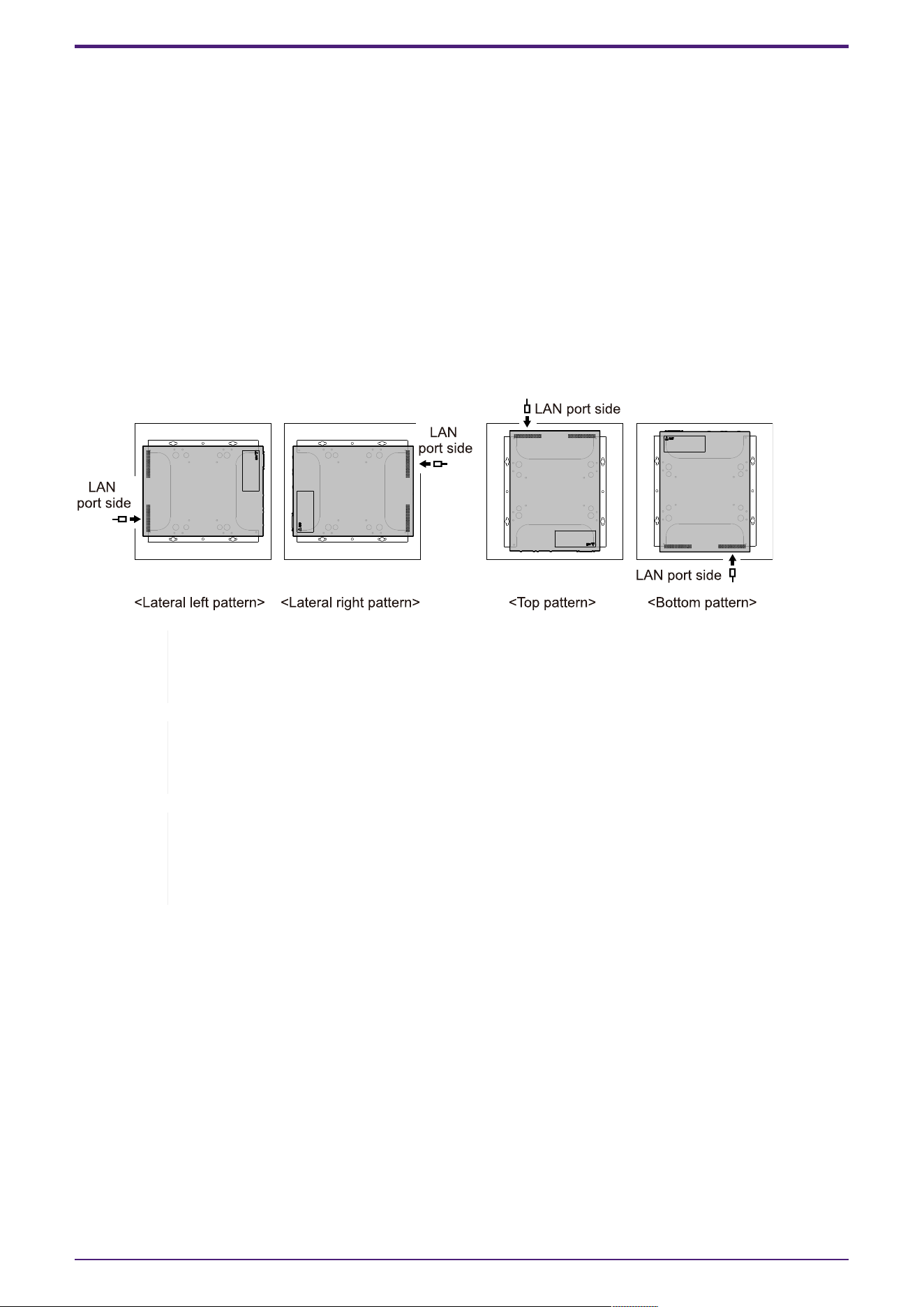
[Mounting patterns]
The unit can be installed with its front, back or side facing up (refer to the illustration below), but not
at an angle.
Warning: When attaching or removing this unit, you must disconnect the unit’s power
plug from the power outlet.
Failing to do so could cause electrical shock or malfunctions.
Caution: Do not install this product in a high place or onto a ceiling.
When installing this product, be sure to install it at a height of 200 cm or less.
If the unit falls, you may be injured or the unit may become damaged.
Note: The mounting accessory has one surface that must be attached to the unit and
one surface that must be attached to the wall. The mounting accessory cannot be
attached to this product using the wrong mounting surface. For details on
distinguishing the surfaces, refer to the illustrations for step 1 and step 3.
3. Installation
12 | L2 Switch SWX2210P-10G Getting Started Guide
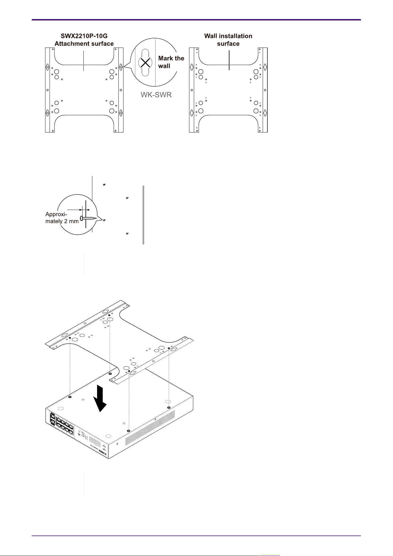
1. Place the mounting accessory against the wall, and mark the installation location.
2. Temporarily fasten the four commercially available screws at the mounting locations marked in
step 1.
At this time, leave approximately 2 mm between the head of each screw and the surface of the
wall, allowing room for the mounting accessory to engage the screws (illustration below).
Caution: You must use screws that are appropriate for the material of the wall.
If the unit falls, you may be injured or the unit may become damaged.
3. Align the unit with the mounting accessory (illustration below).
Important: If there are rubber feet attached to the bottom of this product,
remove them before attaching the mounting accessory.
3. Installation
L2 Switch SWX2210P-10G Getting Started Guide | 13
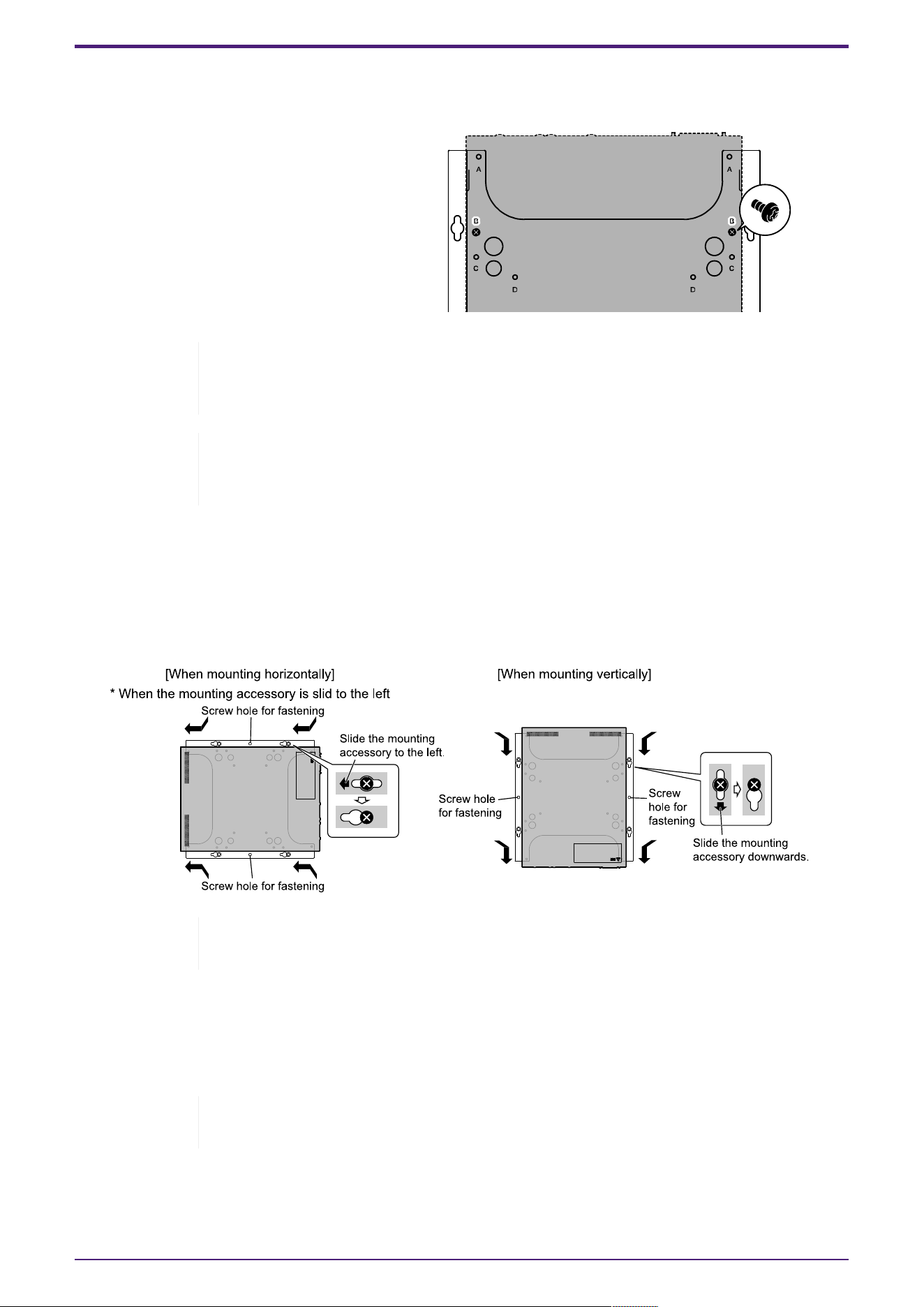
4. Using the four included screws, attach the mounting accessory to the unit.
Use a Phillips screwdriver to firmly fasten the screws.
• Screw hole to be used: B
• Screws to be used: For metal housing
(black small M3 × 4)
Warning : Always use the specified screws provided with the wall mount kit.
If the unit falls, you may be injured or the unit may become damaged. This could
also cause electric shock or malfunctions.
Caution: Use caution when touching the corners of the mounting accessory with
your hands or fingers,
as the corners are sharp and may cause injury.
5. Engage the assembled mounting accessory with the commercially available screws attached to the
wall, and slide the mounting accessory to the side.
Slide the mounting accessory to match the installation direction (refer to the illustration below).
• When installing horizontally: Slide left or right
• When installing vertically: Slide down
Caution: Do not let the unit fall.
If the unit falls, you may be injured or the unit may become damaged.
6. Further tighten the commercially available screws that you provisionally attached, fastening the
mounting accessory.
7. Install commercially available screws in the fastening screw holes (two locations) of the mounting
accessory.
Caution: You must use screws that are appropriate for the material of the wall.
If the unit falls, you may be injured or the unit may become damaged.
3. Installation
14 | L2 Switch SWX2210P-10G Getting Started Guide
4. Connections
4.1. Connecting the power cord
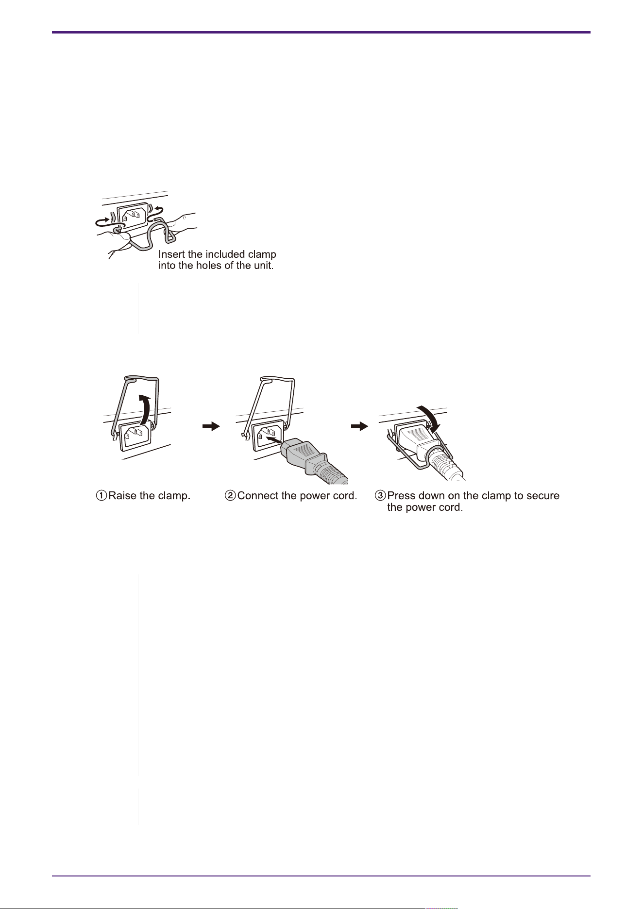
1. Attach the included power cord clamp.
To prevent accidental disconnection of the power cord, insert the included power cord clamp
("included clamp" in the illustration below) into the power cord clamp holes of the unit ("holes in
the unit" in the illustration below) to secure the power cord.
Caution: The included power cord clamp is only for the included power supply
cord. If you use the clamp for other than the included power cord, the cord might
be damaged or might not be properly secured.
2. Connect the included power cord to the power supply inlet, and secure it with the clamp.
3. Connect the power plug to an electrical outlet.
The POWER indicator will light up green.
Caution: If the STATUS indicator is flashing orange, one of the following
problems has occurred: Check the error situation and deal with it appropriately.
◦ Fan stopped
Stop using this product immediately and contact the dealer where you
purchased this product to have the unit inspected and/or repaired.
◦ PoE power supply failure
Stop using this product immediately and contact the dealer where you
purchased this product to have the unit inspected and/or repaired.
◦ Internal temperature abnormal
Review the environment in which this product is installed, and correctly
install this product so that the internal temperature is at an appropriate
level.
Note: This unit does not have a power switch. The power turns on when you
insert the plug of the power cord connected to this unit into a power outlet.
4. Connections
L2 Switch SWX2210P-10G Getting Started Guide | 15
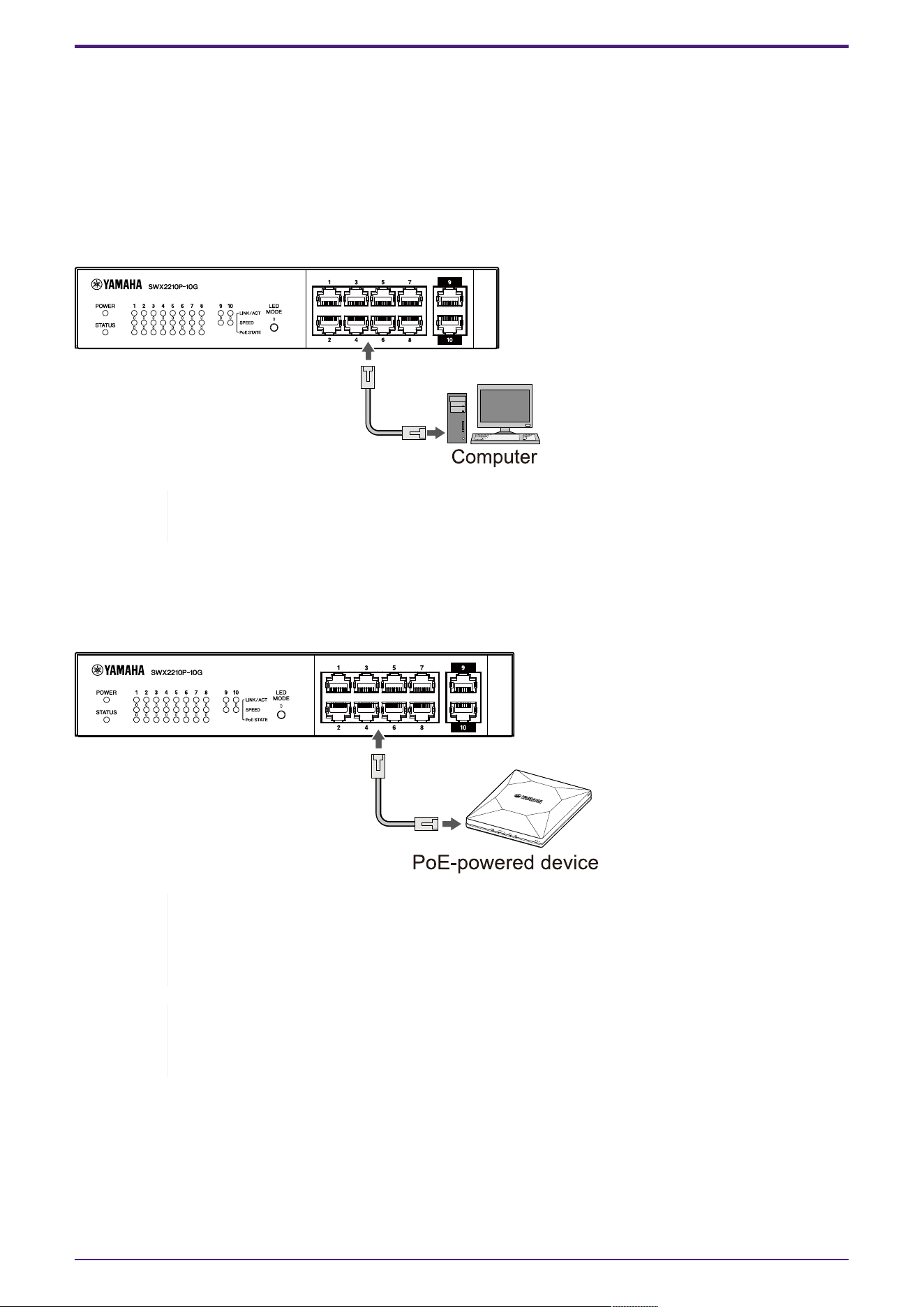
4. Check the port indicators.
Check the LINK/ACT indicators. The LINK/ACT indicator corresponding to the LAN port to which
the network device or computer is connected should be lit green or flashing green.
For details about the indicator status, refer to "LINK/ACT indicators."
4.2. Connecting to a network device or computer
Using LAN cables, connect the LAN port of the network device or computer to the LAN ports of this
unit.
Note: The LINK/ACT indicators indicate the connection status with network devices
and computers. For details on the connection status, refer to "LINK/ACT indicators."
4.3. Connecting PoE-powered devices
Connect the LAN port of the PoE-powered device to the LAN port of this product with a LAN cable.
Warning: When connecting a receiving device that complies with the IEEE802.3at
standard, use a CAT5e or higher cable.
If you do not use a cable that complies with the standard, it may cause a fire or
malfunction.
Note: The PoE STATE indicator allows you to check the power supply status to the
PoE-powered device. For details on the power supply status, refer to "PoE STATE
indicator."
4. Connections
16 | L2 Switch SWX2210P-10G Getting Started Guide

5. Settings
The settings for this product can be made in the following ways.
• Making settings using the Web GUI
• Making settings from the command line using Telnet
• Restoring this unit’s settings to their factory-set defaults
You can log in to this unit either as a standard user or as an administrative user. This section explains
how to log in as an administrative user.
For more information, refer to the "Technical Data" and “Command reference” on the information page
for this product on the Yamaha website.
5.1. Making settings using the Web GUI
This explains how to log in to this unit using the Web GUI.
5.1.1. Logging in to this unit using a web browser
1. Connect this product to the computer with a LAN cable.
2. Check the power supply of this unit.
If this unit is not powered on, turn on the power as described in “Connecting the power cord”.
Once the power is on, go to step 3.
3. Launch the Web browser and access “http://(IP address of this product)/.”
When access is successful, the login screen appears where you can enter a user name and
password.
Note
◦ The IP address of this product is set to “192.168.100.240/24” by default
when shipped from the factory.
◦ If this unit is not connected to a network, change the IP address of the
computer to use for settings to the “192.168.100.0/24” segment.
Refer to the help documentation of your computer for how to change the
computer’s IP address.
4. Enter the user name and password, and click the "Login" button.
If the settings are the factory-set defaults, enter the username "admin" and password "admin" for
the initial administrative user.
After successful login from the factory default state, the language selection screen appears.
Note: If you enter an incorrect username or password three times in a row, you
will be unable to log in to the machine for one minute. In this case, wait at least
one minute and then repeat step 4.
5. Select the language to use.
If you log in with the factory default settings, the password change screen appears.
Note: You can change the language after login from the Web GUI.
6. Enter your new password in both fields and click the "Save" button.
If the password change is successful, the Web GUI home page appears.
5. Settings
L2 Switch SWX2210P-10G Getting Started Guide | 17

5.2. Making settings from the command line using Telnet
This explains how to log in to this unit using a Telnet client from a host on your LAN.
5.2.1. Logging in to this unit using a Telnet client
Use a Telnet client such as a computer to log into this unit and connect to the built-in Telnet server.
Here we explain how to use the Telnet client in Windows to connect to the built-in Telnet server on
this product.
Note: Telnet functionality is disabled on Windows by default. To use Telnet, you will
need to enable the Telnet client.
1. Connect this product to the computer with a LAN cable.
2. Check the power supply of this unit.
If this unit is not powered on, turn on the power as described in “Connecting the power cord”.
Once the power is on, go to step 3.
3. Launch the Windows command prompt.
4.
Enter the IP address of this product in the telnet command, and press the [Enter] key.
When the settings of this unit are still the factory defaults, enter “192.168.100.240” after the
telnet command.
telnet 192.168.100.240
The system waits for a user name to be entered.
5. Enter your user name, and press the [Enter] key.
If the device is in the factory default state, enter the username of the initial administrative user,
"admin".
Username: admin
The system waits for a password to be entered.
6. Enter the password for the user entered in step 5, and press the [Enter] key.
If it is in the factory default state, enter the initial administrative user password "admin".
Password:
Note
◦ The password you enter will not be displayed on the console screen. (The
same applies to the following steps.)
◦ If you enter the wrong password three times in a row, you will be unable to
log in to the product for one minute. In this case, wait at least one minute
and then start over from step 5.
5. Settings
18 | L2 Switch SWX2210P-10G Getting Started Guide

Before changing the initial password of the initial administrative user
If password authentication is successful, you will be prompted to enter a new password.
Proceed to step 7 to change your password.
SWX2210P-10G Rev.1.03.13 (Wed Sep 4 08:33:10 2024)
Ê Copyright (c) 2018-2024 Yamaha Corporation. All Rights Reserved.
Please change the default password for admin.
New Password:
After changing the initial password for the initial administrative user
If password authentication is successful, the command prompt appears and you can enter
commands. This completes the login procedure (no further steps are required).
SWX2210P>
7. Enter the administrator password, and press the [Enter] key.
New Password:
The system waits for your new password to be re-entered.
8. Enter the same password as in step 7 again and press the [Enter] key.
New Password(Confirm):
If the password change is successful, the command prompt appears and you can enter commands.
Saving ...
Succeeded to write configuration
SWX2210P>
For more information about commands, refer to “Command reference” on the information page for this
product on the Yamaha website.
5. Settings
L2 Switch SWX2210P-10G Getting Started Guide | 19

5.3. Restoring this unit’s settings to their factory-set defaults
This explains how to restore this unit’s settings to their factory-set defaults.
• Restoring this unit’s settings to their factory-set defaults from the Web GUI
• Using the “cold start” command to restore the factory settings
• Restoring the factory settings with the LED MODE button
Caution: When restoring the factory settings, note the following points.
• All communication is halted immediately after execution.
• The IP address of this unit will be initialized to the factory default setting
(192.168.100.240).
• You will not be able to restore the current settings once you have restored the
factory settings. If necessary, back up the settings to a computer or the like
before you proceed with restoring the factory settings.
For how to read the config file, refer to “Command reference” on the
information page for this product on the Yamaha website.
Note: Refer to Settings for how to log in after restoring the factory settings.
5.3.1. Restoring this unit’s settings to their factory-set defaults from the
Web GUI
This unit can be restored to its factory-set state by making settings from the Web GUI.
Important: This procedure cannot be performed if the administrative password is set
to the default setting. Please change the administrative password beforehand.
This explanation assumes that you have logged in using the steps in “Logging in to this unit using a
Web browser”.
1. Select the “Administration” tab – “Maintenance” – “Restart or Initialize,” in that order.
The "Restart or Initialize" screen appears.
2. In the "Initialize" section, click the “Proceed” button.
The "Initialize" screen appears.
3. Enter the administrative password, and click the “Confirm” button.
The "Confirm execution" screen appears.
4. Verify the contents, and click the "Execute" button.
The unit is returned to its factory-set state. Also, the “Initialization” dialog box appears, and the
unit reboots.
5. After this unit finishes rebooting, access the Web GUI again.
Note
• During reboot, the computer on which the Web GUI is open will be unable to
communicate with the unit (the status indication of the computer’s network
adapter will be "Network cable is not connected"). Communication will be
restored when the reboot is completed. After the product’s lights stop flashing,
make sure that your computer’s communication status has been restored and
then click "192.168.100.240/24".
5. Settings
20 | L2 Switch SWX2210P-10G Getting Started Guide

• The IP address of this unit will be restored to 192.168.100.240. Once Web GUI is
redisplayed, access “192.168.100.240”.
5.3.2. Using the “cold start” command to restore the factory settings
You can use Telnet to restore the factory default settings from the command line.
Caution: If you are logged in via Telnet, you will be disconnected.
Important: This procedure cannot be performed if the administrative password is set
to the default setting. Please change the admin password beforehand using the
enable password command.
Note: This explanation assumes that you have logged in using the steps in “Making
settings from the command line using Telnet”.
1.
Enter enable , and press the [Enter] key.
The unit switches to privileged EXEC mode.
SWX2210P>enable
SWX2210P#
2.
Enter the cold start command, and press the [Enter] key.
You will be asked to enter the administrative password.
SWX2210P#cold start
Password:
3. Enter the administrative password, and press the [Enter] key.
The settings saved in this unit are returned to their factory-set state, SYSLOG is deleted and
then the unit reboots.
5.3.3. Restoring the factory settings with the LED MODE button
When the power is off, press and hold the LED MODE button on the front panel and then turn the
power on to restore the settings to the factory defaults.
Note: This unit does not have a power switch. The power turns on when you insert
the plug of the power cord connected to this unit into a power outlet.
1. With your finger pressed down on the LED MODE button on the front panel, turn the power on.
The unit will reboot.
2. Press and hold the LED MODE button on the front panel with your finger for approximately 10
seconds.
The settings saved in this unit will be returned to their factory-set state and SYSLOG will be
deleted.
3. When all the indicators except for the POWER indicator and STATUS indicator are lit orange,
release the LED MODE button.
5. Settings
L2 Switch SWX2210P-10G Getting Started Guide | 21

© 2019 Yamaha Corporation
Published 02/2025
HS-B0