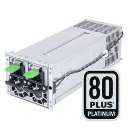

Gemini 800C Platinum
Gemini Series
80 Plus Platinum 800W 2U CRPS
Redundant Power Supply
800W+800W 24hour and well working performance at 45°C fully continuous power output
2U CRPS form factor: 82mm (W) x 102mm (H) x 245mm (D)
80 Plus Platinum certification
Active PFC (full range)
All Japanese electrolytic capacitors
Hot swappable design

SPECIFICATION
SilverStone Gemini Series
Gemini 800C Platinum
SST-GM800C-PF/SST-GM800C-PFU
1+1 2U CRPS Redundant Switching Power Supply
80 PLUS Platinum efficiency certified.
800W+800W
01
1.0 Introduction
2.0 Input Power
This specification defines the electrical and functional characteristics for two
800W Power modules .Unless otherwise noted, the requirements in this specifi-
cation are applicable for each of the above listed power supplies.
The 800W power supply modules will be used for 1+1 redundant (load sharing)
operation and should be designed to be inserted and removed ("hot plugging")
while the system is running.
The power supply must provide a PMBus interface through which the system is
able to read and write various devices. Note that, with 2 power supplies present
in a system (redundant configuration), the I2C devices with-in a power supply
must be accessible even if the power supply has failed or faulted.
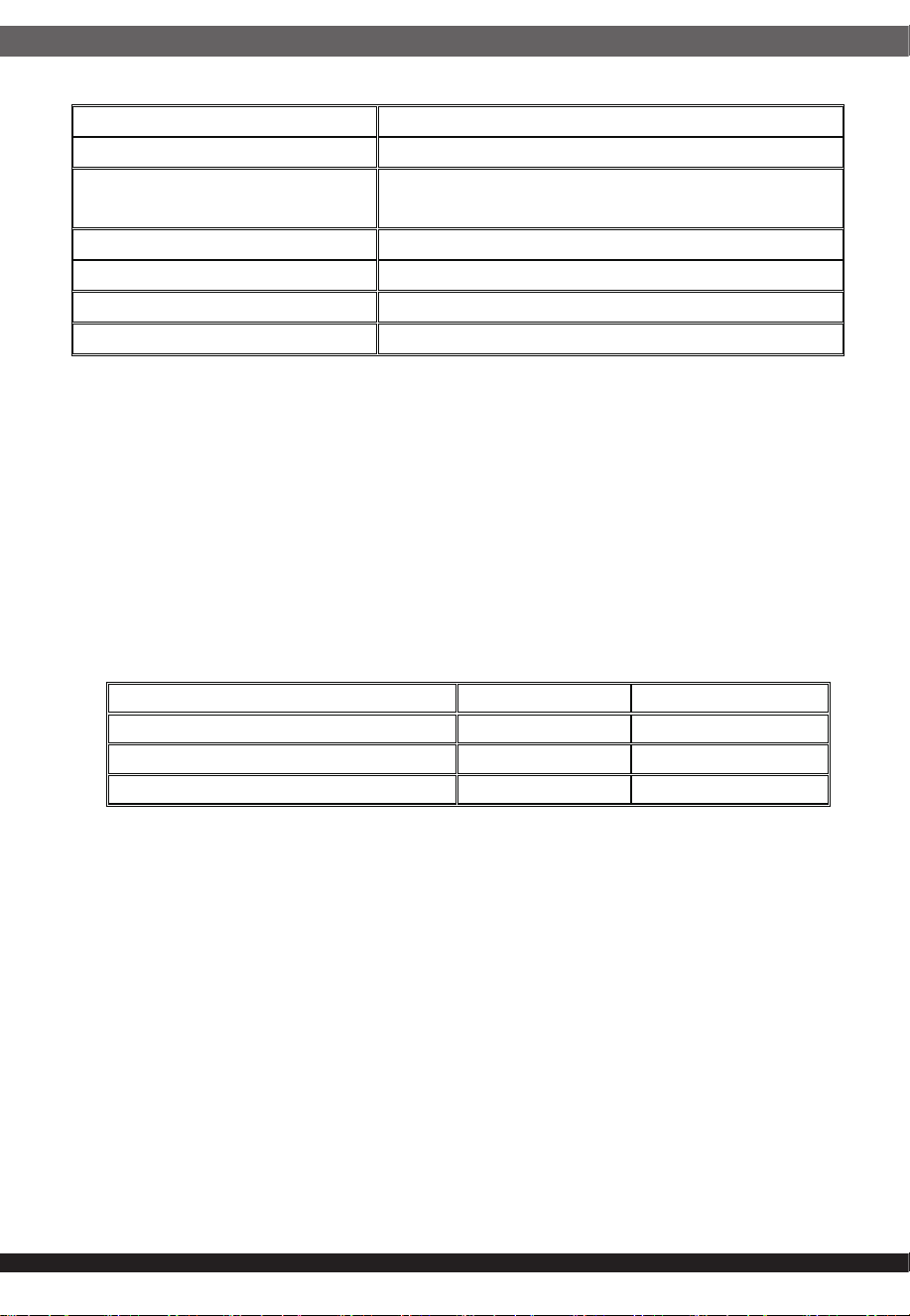
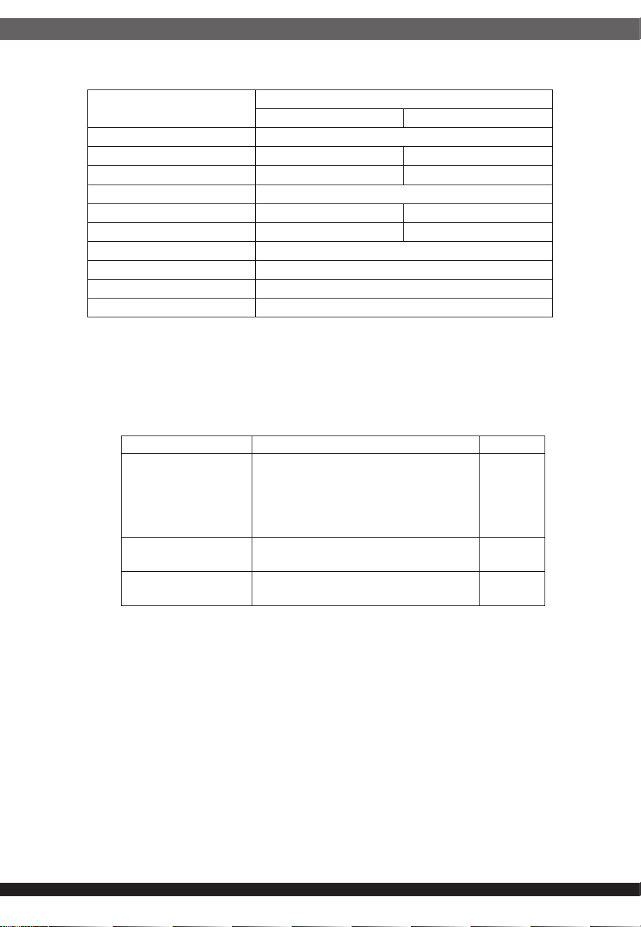
2.1 Voltage and Current
Input voltage
Input current
Parameter Minimum Nominal Maximum
Low Line 90Vrms 100-127Vrms 140Vrms
High Line 180Vrms 200-240Vrms 264Vrms
Frequency 47 Hz 50/60 Hz 63 Hz
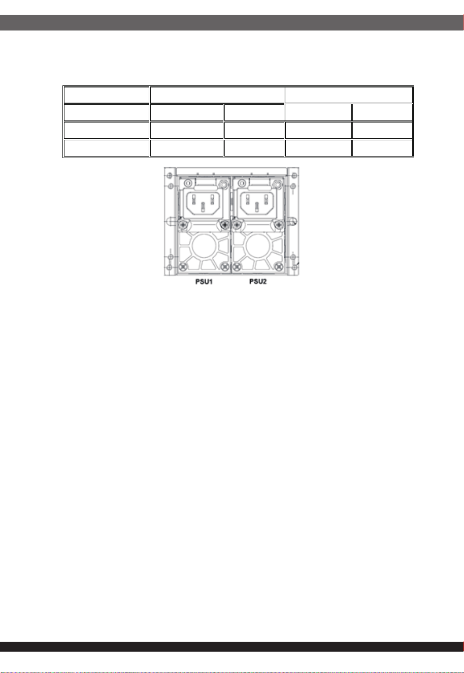
Parameter Maximum Input Current
100-127Vac Input 10A
200-240Vac Input 5A
2.2 Efficiency
3.1 Voltage and Current
3.2 Ripple and Noise
※1. At 264Vac 25
°C
, max load cold start, any Inrush current spike shall not
exceed 35A peak.
※2. At 90~264Vac 25
°C
, max load hot start, any inrush current of the AC line
shall not cause damage to the power supply.
Output voltage and current
※1. Maximum combined power on +3.3V and +5V shall not exceed 170W.
※2. Maximum combined power for all output shall not exceed 800W.
3.0 Output Power
02
Only power module efficiency meet Cybenetics Platinum at all specified load
points. The efficiency should be measured at 230VAC and with external fan
power according to Climate efficiency measurement specifications.
2.3 Power Factor
The power factor of the power supply should greater than 0.95 at 115Vac/60Hz
input voltage and 50% of maximum load.
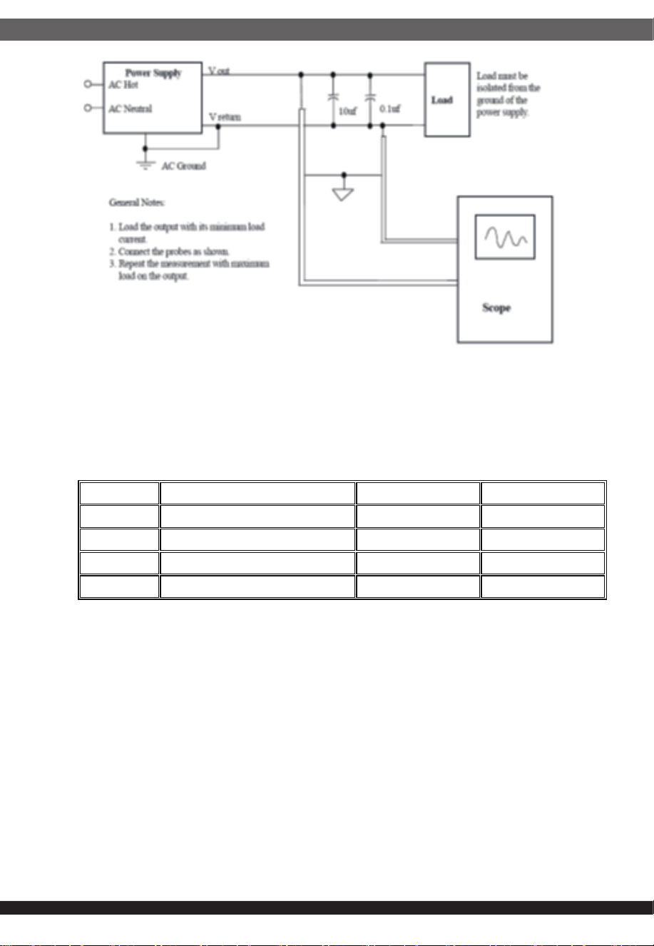
The maximum allowed ripple and noise output of the power supply is defined in
below table. This is measured over a bandwidth of 10Hz to 20MHz at the power
supply output connectors. A 10uF low ESR electrolytic capacitor in parallel with
a 0.1uF ceramic capacitor is placed at the point of measurement. To help
reduce switching ripple further, an additional 2200uF low ESR electrolytic
capacitor may be placed in parallel.
Measurements made where the cable connectors attach to the load.
2.4 Harmonic Current
The harmonic current of the power supply shall be measured at the maximum
load with input voltage of 230Vac/50Hz. Meet EN 61000-3-2, Class A.
Voltage +3.3V +5V +12V -12V +5Vsb
Maximum load 25A 25A 65A 0.8A 3.5A
Minimum load 1A 1A 1A 0A 0.1A
Max. power
170W *
1
780W 9.6W 17.5W
Total power 800W*
2
Regulation limit ±5% ±5% ±5% ±10% ±5%
Output +5V +3.3V +12V -12V +5Vsb
Ripple & Noise 50mVp-p 50mVp-p 120mVp-p 120mVp-p 50mVp-p
03
3.3 Dynamic Loads
3.4 Hot Swap Transient Load
The output voltages shall remain within limits specified for the step loading
and capacitive loading specified in the test table below. The load transient
repetition rate shall be tested between 50Hz and 5KHz frequency and above
25% load.
When an additional power module is ORed together, or, removed from a
group of one power module, the outputs shall maintain regulation.
3.5 Turn On/Off Overshoot
Overshoot at turn on shall be less than 10% of the nominal output voltage.
3.6 Load Capacitance
The power supply shall be stable and meet all requirements with the follow-
ing capacitive loading ranges.
Output Step load Load slew rate Capacitive load
+12V 60% of max load 0.5A/us 18000uF
+5V 30% of max load 0.5A/us 5000uF
+3.3V 30% of max load 0.5A/us 5000uF
+5Vsb 50% of max load 0.5A/us 350uF
04
Output Min. Max.
+12V 500uF 18000uF
+5V 400uF 5000uF
+3.3V 250uF 5000uF
-12V 1uF 350uF
+5Vsb 20uF 350uF
4.0 Protection
4.1 Shutdown Definition
4.2 Over Current Protection
4.3 Over Voltage Protection
If the power supply is protected when OCP, OVP, OTP or short protection
(except
+5Vsb), the power supply shall shut down and latch off. The power supply
return to normal operation after the fault condition has been remove and
PS_ON signal must reset for OFF/ON cycle with a minimum OFF time of 1
second or AC power must reset for OFF/ON cycle with a minimum OFF time
more than 1 minute. Then it will turn on again.
+5Vsb by output protection shall be auto recovery.
Shutdown is defined as a condition where the +12V, +5V, +3.3V and -12V
outputs latches off. The +5Vsb output shall remain on.
The overload currents testing slew rate is 10 A/s starting from maximum
load.
The over voltage sense circuitry and reference shall reside in packages that
are separate and distinct from the regulator control circuitry and reference.
The power supply shall provide latch off mode for over voltage protection
as defined in below.
Output Over current limit Protection type
+5V 27.5A~37.5A Latch off
+3.3V 27.5A~37.5A Latch off
+12V <91A Latch off
+5Vsb <9A Auto recovery
Output Over voltage threshold Protection type
+5V 5.6V~6.5V Latch off
+3.3V 3.8V~4.5V Latch off
+12V 13.2V~15.6V Latch off
05
4.4 Short Circuit Protection
An output short circuit is defined as any output impedance of less than 10m
Ω. The power supply shall shut down and latch off for shorting the +3.3V,
+5V, or +12V rails to return.
The +5Vsb power supply will not latch under short circuit condition on
+5Vsb output. It will return to its normal operating mode once the short
circuit is removed.
4.5 Over Temperature Protection
The power supply shall have thermal protection against over temperature
condition caused by loss of airflow or excessive ambient or hot spot
temperature. The PSU should shut down and latch off when over tempera-
ture triggered.
4.6 Fan Fault Protection
After 10 sec the power supply should be latch off when fan fault occur.
When fan speed malfunction, fan warning signal should be sent it out first
then latch off the power supply.
4.7 Backplane Buzzer Alarm
4.8 LED Indicator
When power supply operate at 1+1 redundant mod, if any one of power
supplies fails, the buzzer should make a continuous sound.
All LEDs shall protrude beyond the supply chassis surface for good visibili-
ty. There is a bi-color LED.
4.7.1 Two Ways to Stop the Buzzer Sound
1. Remove the damaged power.
2. Press the push switch.
Power Supply Condition LEDs State
No AC power OFF
Only standby output on Blink green
Power supply outputs ON and OK Green
Power supply failure Amber or Blink green
5.1 Hold-up Time
06
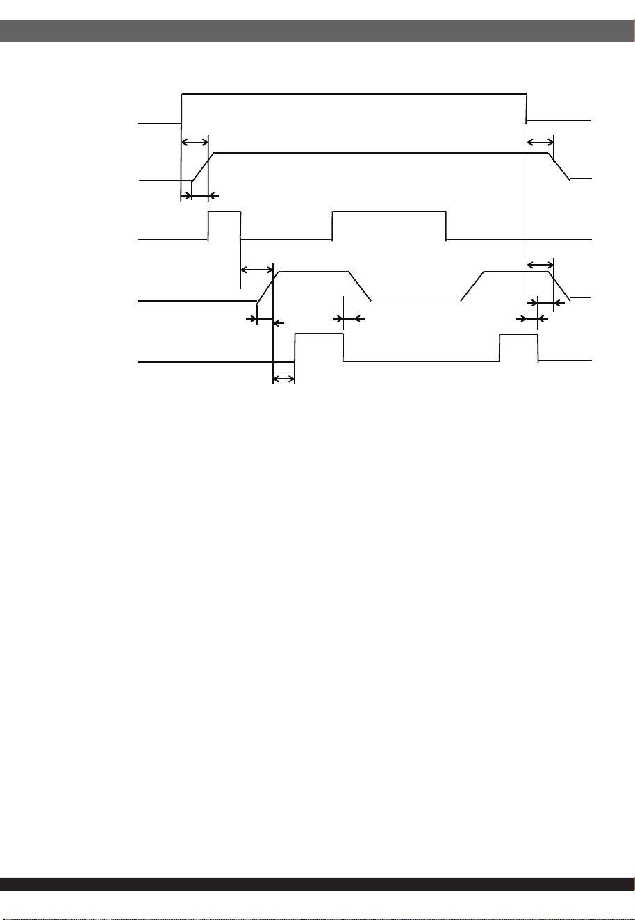
5.0 Sequencing and Signals
T1: +5Vsb power on delay time ≦ 1.5s.
T2: The output voltages rise time from 10% to 90% during 0.1ms to 70ms.
T3: PWOK signal delay time during 100ms to 500ms.
T4: AC loss to PWOK signal hold up time ≧ 10ms.
T5: PWOK signal turn off delay time ≧ 1ms.
T6: Power on delay time ≦ 400ms.
T7: AC loss to +5Vsb output hold up time ≧ 50ms.
Outputs
+12V, +5V, +3.3V
T4: 10ms MIN
12ms MIN
T7: 50ms MIN
T3: 100ms~500ms
PS ON
PWOK
T5: 1ms MIN
T5: 1ms MIN
AC ON
T2: 0.1~70ms
+5Vsb
T6: 400ms MAX
T1: 1.5S MAX
T2: 0.1~70ms
When AC is removed, the output must remain regulation for at least 12ms
with 70% of maximum load and over 100-240VAC input.
5.2 PWOK Signal
PWOK is an active high output signal from the power supply used to
indicate that:
1.The PS ON signal is active low
2.The +12V, +5V and +3.3V outputs is above its under voltage threshold
and below its over voltage threshold
3.The load is below the over current threshold
4.The power supply is operating normally and within thermal limits.
If the PWOK signal transitions from high to low (de-asserted) shows the
power supply shut down.
07
5.4 Power on Delay Time
5.3 PS ON Signal on/off Control
5.5 Rise time
5.6 Serial Bus Interface
The electrical and timing characteristics of the PWOK signal are given in below.
Signal type +5V TTL compatible
Logic level low
< 0.4V while sinking 4 mA
Logic level high Between 2.4V and 5.25V output while sourcing
200 uA
High state output impedance 1KΩ
PWOK delay time
100ms < T3 < 500ms
AC loss to PWOK hold up time T4 ≧ 10ms
PWOK turn off delay time T5 ≧ 1ms
5. For test purposes, the PWOK signal shall be terminated at the output
power supply connector with a 0.01uF ceramic capacitor.
6. When only one power module, the AC loss to PWOK hold up time ≧
10ms at 70% load condition.
PS ON is an active-low, TTL-compatible signal that allows a motherboard
to remotely control the power supply in conjunction with features such as
soft on/off. The OFF/ON cycle with a minimum OFF time is 1s.
The power supply shall provide an internal pull-up to TTL high. The power
supply shall also provide de-bounce circuitry on PS ON to prevent it from
oscillating on/off at startup when activated by a mechanical switch.
The power-on time is defined as the time from when PS ON is pulled low to
when the +12V, +5V and +3.3V outputs are within the regulation ranges
specified in Section 3.1. The power-on time shall be less than 400ms.
The output voltages shall rise from 10% to 90% of nominal to within the
regulation ranges specified in Section 3.1 within 0.1ms to 70ms.
The system will utilize PMBus for communication between itself and the
power supply. The bus is to be compatible with both SMBus 2.0‘high power’
and I2C. The bus will be 3.3V. A voltage shifting circuit may be needed to
accomplish this. Except where specifically called out, there will be no
pull-ups in the power supply. The pull-ups will be provided external to the
power supply via 4.7K~10Kohm in the host system.
Signal Minimum Maximum
V
IL
, Input Low Voltage
0V 0.8V
I
IL
, Input Low Current (Vin = 0.4 V)
- -1.6mA
V
IH
, Input High Voltage
2.0V 5.25V
5.6.1 Address (ADDR)
5.6.2 SCL and SDA
08
The PMbus device address locations are shown below.
PSU PMBUS Address FRU Address
Binary Hex Binary Hex
PSU1 1011 0000 B0 1010 0000 A0
PSU2 1011 0010 B2 1010 0010 A2
SCL and SDA comprise a bi-directional serial data bus used to commu-
nicate between the SMBus devices with-in the power supply and the
host system.
The host system has pull-ups on these signals; the power supply must
not.
The power supply may be used in a system with up to one additional, redun-
dant, power supplies. The load is shared between the power supplies that are
ORed together. When two supplies are ORed together, they may be used in
1+1 configuration.
7.1.1 UL/cUL UL62368-1, 3rd Edition
7.1.2 TUV EN62368-1, 3rd Edition
7.1.3 CB IEC62368-1, 3rd Edition
.
6.0 Redundant Operation
7.0 SAFETY AND EMS REQUIREMENTS
7.1 Safety requirments
EN55032 / EN55035 requirements
7.2 EMC requirements
7.2.1.1 Meet FCC part 15 class A.
7.2.1.2 Meet EN55032 class A.
7.2.1 EMI Requirements

09
Meet IEC61000-4-2 level 4, Criteria A for contact +/- 8KV and air
+/-15KV.
7.2.2 Electrostatic Discharge Immunity Test (ESD)
Meet IEC61000-4-3 level 3, Criteria A for 80~1000MHz, 10V/m.
7.2.3 Radio Frequency Electromagnetic Field Immunity Test (RS)
Meet IEC61000-4-4 level 3, Criteria A for L to N 2KV
7.2.4 Electrical Fast Transient/Burst Immunity Test (EFT/BURST)
Meet IEC61000-4-5 level 3, L to N 1KV, line to Earth 2KV, Criteria A.
7.2.5 Surge Immunity Test
Meet IEC61000-4-6 level 3, Criterion A for 0.15~80MHz, 10V/m.
7.2.6 Conducted Disturbances Induced by Radio-Frequency Field
Immunity Test
Meet IEC61000-4-8 level 3, Criterion A for 50Hz, 10A/m.
7.2.7 Power Frequency Magnetic Field Immunity Test
Meet IEC61000-4-11
Criterion B for 0% residual 0.5 cycle at 50Hz.
Criterion C for 70% residual 25/30 cycles at 50Hz/60Hz.
Criterion C for 0% residual 250/300 cycles at 50Hz/60Hz.
7.2.8 Voltage Dips and Voltage Interruptions Immunity Test
Meet EN 61000-3-2 Class A.
7.2.9 Suppression of Harmonics Test
Meet EN 61000-3-3
7.2.10 Voltage Fluctuations Test
Each unit must pass a 1.8KV (AC) between line and ground (FG)
hi-pot test for a minimum of 3 second without failure, current limit
10mA.
7.2.11 Dielectric Strength Test
AC input 264V/63Hz, touch current should not exceed 3.5mA.
7.2.12 Touch Current Test
Line to ground/chassis, input DC 500V,3 seconds >20MΩ at 25
°C
and relative humidity 70% of reference.
7.2.13 Insulation Resistance Test

8.0 Environment
9.0 Reliability
8.1. Temperature
10
8.1.1 Operation temperature of the supply will be between 0
°C
to 45
°C
8.1.2 Storage temperature of the supply will be -40
°C
to +80
°C
.
>300,000 Hours at 230Vac/50HZ maximum load 25℃ condition. The
failure rate shall be calculated with Telcordia SR-332 issue 4.
8.2. Humidity
8.2.1 Operation relative humidity of the supply will be between 10% and
90% (non-condensing).
8.2.2 Storage relative humidity of the supply will be between 5% and 95%
(non-condensing).
9.1 MTBF
10.0 Dimension
The power supply dimension is 245mm (L) x 84.8mm (W) x 82mm (H).
(Refer to outline drawing)
9.2.1 Operating
2.94 , 10-500Hz, 10 minutes per cycle, 30 minutes for each X, Y
and Z axis.
9.2.2 Non-operating
5.88 , 10-500Hz, 10 minutes per cycle, 30 minutes for each X, Y
and Z axis.
9.2 Vibration
Non-operating (package):20G, half sin-wave, each per axis.
9.3 Shock
8.3.1 The maximum operation altitude of the supply is 5000 meter.
(The ambient operating temperature decreases by 1°C for every
305m increase in altitude.)
8.3.2 The maximum storage altitude of the supply is 15000 meter.
11
11.0 Serial Bus Commands
This feature only the power module (TG17-0800-01) support
11.1 PMBus
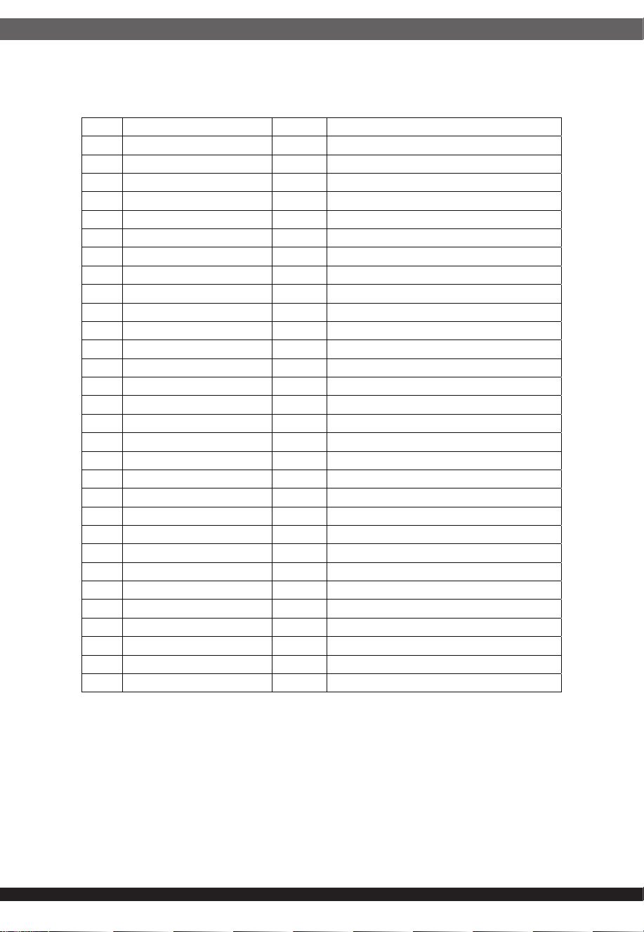
Code Command Bytes Read / Write
01h Operation 1 Read / Write
03h Clear_Faults 0 Write
05h Page_Plus_Write Variable Block Write
06h Page_Plus_Read Variable Block Write – Block Read Process Call
19h Capability 1 Read
1Ah Query 1 Block Write – Block Read Process Call
1Bh SMBALERT_Mask 2 Block Write – Block Read Process Call
20h Vout_Mode 1 Read
30h Coefficients 5 Block Write – Block Read Process Call
78h Status_Byte 1 Read
79h Status_Word 2 Read
7Ah Status_Vout 1 Read
7Bh Status_Iout 1 Read
7Ch Status_Input 1 Read
7Dh Status_Temperature 1 Read
7Eh Status_CML 1 Read
81h Status_Fans 1 Read
86h Read_Ein 6 Block Read
87h Read_Eout 6 Block Read
88h Read_Vin 2 Read
89h Read_Iin 2 Read
8Bh Read_Vout 2 Read
8Ch Read_Iout 2 Read
8Dh Read_Temperature1 2 Read
8Eh Read_Temperature2 2 Read
8Fh Read_Temperature3 2 Read
90h Read_Fan speed 2 Read
96h Read_Pout 2 Read
97h Read_Pin 2 Read
98h PMBus_Revision 1 Read
The power supply will provide the following access via PMBus
protocol:
● Power supply status
● Input/output power metering
In the following sections, all operations, values and definitions are in
compliance with the PMBus specifications unless explicitly noted.
Only PMBus commands and bits explicitly identified in the tables
under Section 13.2 are supported. Therefore, any attempt to write
using these commands must be handled as unsupported.
12
11.2 PMBus Command Summary
PMBus commands are one byte command codes. As below listing is
power supply can support of PMBus commands.
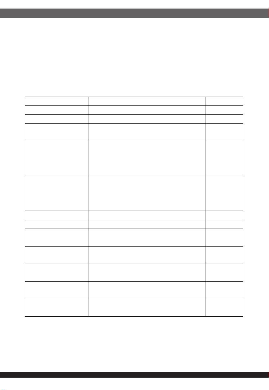
11.2.1 Read commands
The READ commands allow the host to read temperature, current,
voltage, power and energy parameters of the power supply.
PMBus direct format set m = 01h, R = 00h, b = 00h.
PMBus command Description Data format
Read_Vin Returns the input voltage in voltage. Linear
Read_Iin Returns the input current in amperes. Linear
Read_Pin
Returns the input power, in watts, of the
power supply.
Linear
Read_Ein
Commands are used to return
information the host can use to calculate
the input power consumption of power
supply.
Direct
Read_Eout
Commands are used to return
information the host can use to calculate
the output power consumption of power
supply.
Direct
Read_Vout Returns the output voltage in voltage. Linear
Read_Iout Returns the output current in amperes. Linear
Read_Pout
Returns the output power, in watts, of the
power supply.
Linear
Read_Temperature_1
Returns the temperature in
°C
of the
airflow inside temperature.
Linear
Read_Temperature_2
Returns the temperature in
°C
of the hot
spot temperature.
Linear
Read_Temperature_3
Returns the temperature in
°C
of the
Primary side hot spot temperature.
Linear
Read_Fan speed
Returns the fan speed in revolutions per
minute
Linear
13
Accuracy
Accuracy
Pin < 100W Pin > 100W
Read_Vin
±5%
Read_Iin
±0.1A ±5%
Read_Pin
±10W ±5%
Read_Vout
±5%
Read_Iout
±0.5A ±5%
Read_Pout
±10W ±5%
Read_Temperature_1
±5℃
Read_Temperature_2
±5℃
Read_Temperature_3
±5℃
Read_Fan speed
<9000rpm±1000rpm; >9000rpm±2000rpm
11.2.2 Capability and inventory reporting
The follow commands shall be supported for discovery of the
power supplies capabilities.
11.2.3 PAGE_PLUS_WRITE
The PAGE_PLUS_WRITE command is used to set the page within a
device, send a command, and send the data for the command in one
packet.
11.2.4 PAGE_PLUS_READ
The PAGE_PLUS_READ command is used to set the page within a
device, send a command, and read the data returned by the command
in one packet.
Command Meaning Value
Capability
Packet Error Checking is supported
Maximum supported bus speed is
100KHz
Support the SMBus Alert Response
protocol
90h
Query
Used to determine if the PSU supports a
specific command
Byte
PMBus_Revision
Used to verify the PMBus revision the
power supply is base on
22h
14
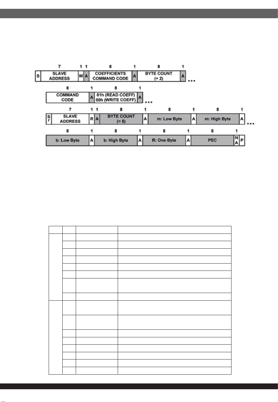
11.2.5 Coefficients
This command is used to retrieve the m, b and R coefficients needed by
data in the DIRECT format.
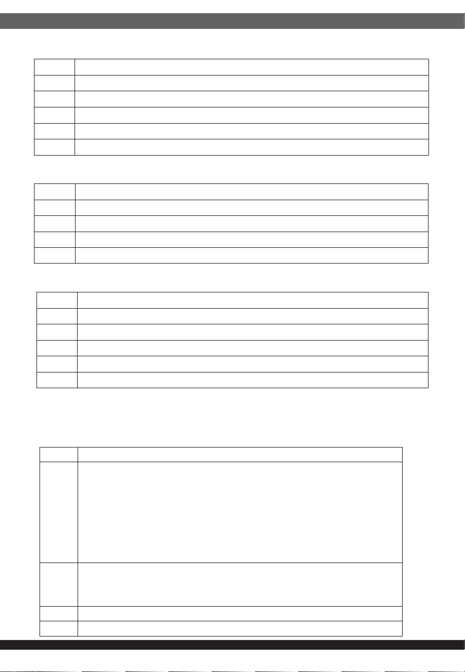
11.2.6 Status commands
Status information is binary. A value of 1 indicates a fault or warning
event has occurred and a value of 0 indicates that a fault or warning
event has not occurred.
When the power an exception occurs, will set the warning bit. Warning
bit will be automatically cleared when the anomalies remove.
The Status_Byte (78h) and Status_Word (79h) message content is
described as shown below.
Byte Bits Bit name Meaning
Low
7 Busy Not support, set to 0
6 OFF +12V output off set to 1
5 Vout_OV_Fault +12V output overvoltage fault has occurred
4 Iout_OC_Fault +12V output overcurrent fault has occurred
3 Vin_UV_Fault Input under voltage fault has occurred
2 Temperature A temperature fault or warning has occurred
1CML
A communications, memory or logic fault has
occurred
0 None of above Not support, set to 0
High
7Vout
+12V output voltage fault or warning has
occurred
6Iout
+12V output current fault or warning has
occurred
5 Input An input voltage fault or warning has occurred
4 Not use Not support, set to 0
3 Power_Good# The PWOK signal, if present, is negated
2 Fans A fan or airflow fault or warning has occurred
1 Other Not support, set to 0
0 Not use Not support, set to 0
15
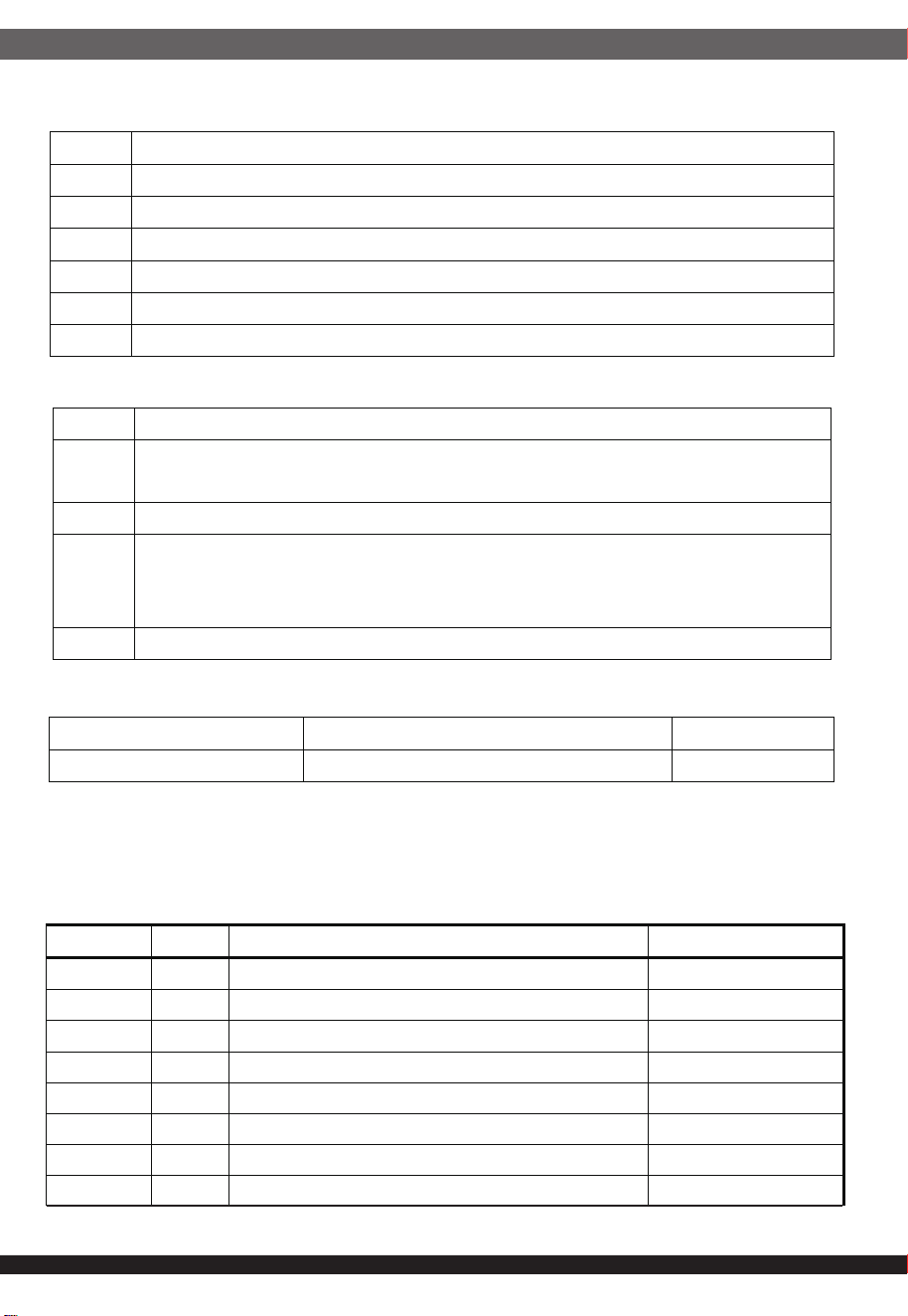
The Status_Vout (7Ah) command returns one data byte with contents as below:
The Status_Iout (7Bh) command returns one data byte with contents as below:
The Status_Input (7Ch) command returns one data byte with contents as below:
Notes:
1.Input voltage sense in front of PSU.
The Status_Temperature (7Dh) command returns one data byte with contents
as below:
Bits Meaning
7 +12V output voltage exceed 14V has occurred (Fault)
6 +12V output voltage exceed 13.2V has occurred (Warning)
5 +12V output voltage less than 10.8V has occurred (Warning)
4 +12V output voltage less than 10V has occurred (Fault)
3-0 Not support, set to 0
Bits Meaning
7 +12V output current exceed 75A has occurred (Fault)
6 Not support, set to 0
5 SMBaltert# low means Warring has occurred.
4-0 Not support, set to 0
Bits Meaning
7-6 Not support, set to 0
5
Input voltage less than 80±5Vrms
1
has occurred (Warning)
4
Input voltage less than 74±5Vrms
1
has occurred (Fault)
3 Unit Off For Insufficient Input Voltage
2-0 Not support, set to 0
Bits Meaning
7
Fault setting:
Temperature (The power supply into the airflow inside) exceed 66
±4
°C
or Secondary hot spot exceed 115 ±5
°C
or Primary side hot
spot exceed 115±5
°C
Recover setting:
Temperature less than 55 ±5
°C
and Secondary hot spot less than
70 ±5
°C
and Primary side hot spot less than 70±5
°C
6
Temperature (The power supply into the airflow inside) exceed 62
±4
°C
(Warning) or Primary/Secondary side hot spot exceed 110±5
°C
(Warning)
5-4 Not support, set to 0
3-0 Reserved, read 0
16
The Status_CML (7Eh) command returns one data byte with contents as below:
The Status_Fans (81h) command reports on the status of fans installed in position
11.3 Output Voltage Related Commands
11.3.1 FRU Data Format
The information to be contained in the FRU device is shown in the
following table.
Bits Meaning
7 Invalid Or Unsupported Command Received
6 Invalid Or Unsupported Data Received
5 Packet Error Check Failed
4-3 Not support, set to 0
2 Reserved, read 0
1-0 Not support, set to 0
Bits Meaning
7
Fan speed less than 800 rpm during over 10 seconds
If the fan control to stop condition will not set this bit
6 Not support, set to 0
5
Fan speed less than target 3800 rpm, during over 5 seconds
If the fan control target less than 4600 rpm, The warning and fault bit
may be together setting.
4-0 Not support, set to 0
Command Meaning Value
VOUT_MODE Linear data format, N = -9 17h
Address Value Description Remark
00H 01 Common header format version Common header
01H 00 Internal use area starting offset No used
02H 00 Chassis info area starting offset No used
03H 00 Board area starting offset No used
04H 01 Product info area starting offset
05H 0A Multi record area starting offset
06H 00 PAD
07H F4 Common Header Checksum
17
08H 01 Product area format version Product header
09H 09 Product area length
0AH 19 Language (English)
0BH C9 Manufacturer name / length
0CH 4C L
0DH 45 E
0EH 41
A
0FH 44 D
10H 20
11H 59 Y
12H 45 E
13H 41
A
14H 52 R
15H CC Model number / length
16H 54 T
17H 47 G
18H 31 1
19H 37 7
1AH 2D -
1BH 30 0
1CH 38 8
1DH 30 0
1EH 30 0
1FH 2D -
20H 30 0
21H 31 1
22H CF Customer information (max 15 bytes) Customer Name
23H 58
X: ASCII code
24H 58
X: ASCII code
25H 58
X: ASCII code
26H 58
X: ASCII code
27H 58
X: ASCII code
28H 58
X: ASCII code
29H 58
X: ASCII code
2AH 58
X: ASCII code
2BH 58
X: ASCII code
2CH 58
X: ASCII code
2DH 58
X: ASCII code
2EH 58
X: ASCII code
2FH 58
X: ASCII code
18
30H 58
X: ASCII code
31H 58
X: ASCII code
32H C3 Product version / length
33H 58
X:From A to Z
To be updated
34H 58
X:From 0 to 9
To be updated
35H 58
X:Reserve
To be updated
36H CF Product serial number / length
37H 58
X:T = LEAD YEAR, M = SMART, C = AMAX
To be updated
38H 58
X:For LEAD YEAR model code (2 bytes)
39H 58 X
3AH 58
X:Year (00~99) date code
To be updated
3BH 58 X To be updated
3CH 58
X:Week (01~52)
To be updated
3DH 58 X To be updated
3EH 58
X:Product version (2 bytes)
To be updated
3FH 58 X To be updated
40H 58
X:Serial number (000001~999999)
To be updated
41H 58 X To be updated
42H 58 X To be updated
43H 58 X To be updated
44H 58 X To be updated
45H 58 X To be updated
46H C0
A
sset tag / length
47H C0 FRU File ID type/length byte
48H C1 No more info fields
49H 00 PAD (Always zero)
4AH 00 PAD (Always zero)
4BH 00 PAD (Always zero)
4CH 00 PAD (Always zero)
4DH 00 PAD (Always zero)
4EH 00 PAD (Always zero)
4FH 61 Product area checksum
50H 00 Power supply information Multirecord
51H 02 Record format version Header
52H 18 Record length
53H 96 Record checksum To be updated
54H 50 Header checksum To be updated
55H 0C Output power (2 bytes) 780W
19
56H 03
57H 28 Peak VA (2 bytes) 1320W
58H 05
59H 23 Inrush current 35A
5AH 0A Inrush interval in ms 10ms
5BH 10 Low end Input voltage range 1 100V
5CH 27
5DH C0 High end Input voltage range 1 240V
5EH 5D
5FH 28 Low end Input voltage range 2 90V
60H 23
61H 20 High end Input voltage range 2 264V
62H 67
63H 2F Low end Input frequency range 47Hz
64H 3F High end Input frequency range 63Hz
65H 0C Input dropout tolerance in ms 12ms
66H 1A Hot swap, Power factor correction support
67H
54
Peak wattages
852W
68H F3 15S
69H 00 Combined Wattage (3 bytes) No used
6AH 00 No used
6BH 00 No used
6CH 00 Predictive fail tachometer lower threshold (RPS)
6DH 01 DC output Multirecord
6EH 02 Record format version Header
6FH 0D Record length
70H 86 Record checksum
71H 6A Header checksum
72H 01 Output number 1 +12V
73H B0 Nominal voltage 12V
74H 04
75H 74 Maximum negative voltage 11.4V
76H 04
77H EC Maximum positive voltage 12.6V
78H 04
79H 78 Ripple and noise pk-pk 10Hz to 20MHz 120mV
7AH 00
7BH 00 Minimum output current 0A
20
7CH 00
7DH E8 Maximum output current 65A
7EH FD
7FH 01 DC output Multirecord
80H 82 Record format version Header
81H 0D Record length
82H AE Record checksum
83H C2 Header checksum
84H 82 Output number 2 +12Vsb
85H B0 Nominal voltage 12V
86H 04
87H 74 Maximum negative voltage 11.4V
88H 04
89H EC Maximum positive voltage 12.6V
8AH 04
8BH 78 Ripple and noise pk-pk 10Hz to 20MHz 120mV
8CH 00
8DH 00 Minimum output current 0A
8EH 00
8FH 34 Maximum output current 2.1A
90H 08
91H
|
FFH
FF Don't used
Field replaceable unit data memory (Hex) show in below table:
Offset 0 1 2 3 4 5 6 7 8 9 A B C D E F
00 01 00 00 00 01 0A 00 F4 01 09 19 C9 4C 45 41 44
10 20 59 45 41 52 CC 54 47 31 37 2D 30 38 30 30 2D
20 30 31 CF 58 58 58 58 58 58 58 58 58 58 58 58 58
30 58 58 C3 58 58 58 CF 58 58 58 58 58 58 58 58 58
40 58 58 58 58 58 58 C0 C0 C1 00 00 00 00 00 00 61
50 00 02 18 96 50 0C 03 28 05 23 0A 10 27 C0 5D 28
60 23 20 67 2F 3F 0C 1A 54 F3 00 00 00 00 01 02 0D
70 86 6A 01 B0 04 74 04 EC 04 78 00 00 00 E8 FD 01
80 82 0D AE C2 82 B0 04 74 04 EC 04 78 00 00 00 34
90 08 FF FF FF FF FF FF FF FF FF FF FF FF FF FF FF
A0 FF FF FF FF FF FF FF FF FF FF FF FF FF FF FF FF
B0 FF FF FF FF FF FF FF FF FF FF FF FF FF FF FF FF
C0 FF FF FF FF FF FF FF FF FF FF FF FF FF FF FF FF
D0 FF FF FF FF FF FF FF FF FF FF FF FF FF FF FF FF
E0 FF FF FF FF FF FF FF FF FF FF FF FF FF FF FF FF
F0 FF FF FF FF FF FF FF FF FF FF FF FF FF FF FF FF
21
12.0 POWER SUPPLY CONNECTOR OVERUSE DEFINITION
Power supply connector overuse definition
EN
A single PCIe 8pin cable and connector’s maximum current rating is
12.5A, which is 150W (+12V x 12.5A). So SilverStone’s warranty will not
cover damages or malfunction resulting from the use of a graphics card
or expansion card with a single PCIe 8pin connector that exceeds
standard 225W total power draw (150W from PCIe 8pin connector +
75W from PCIe motherboard slot). Similarly, a graphics card or
expansion card with dual PCIe 8pin connectors that exceed 375W total
power draw (300W from two PCIe 8pin connectors + 75W from PCIe
motherboard slot) will also not be covered under warranty.
Peripheral (molex) or SATA connector’s maximum current rating is 5A,
which is 60W (+12V x 5A) or 25W (+5V x 5A). Please ensure connected
devices are operating under these limits. SilverStone’s warranty will not
cover damages or malfunction resulting from usages exceeding these
connectors and their associated cables.
24pin motherboard connector’s maximum current rating for its dual
+12V metal pins are 5A each, which totals 120W (+12V x 5A x 2).
Please ensure +12V drawing devices connected to the motherboard are
operating under these limits. SilverStone’s warranty will not cover
damages or malfunction resulting from usages exceeding these
connectors and their associated cables.
Definition einer Überlastung des
Netzanschlusses
DE
Die maximale Stromstärke eines einzelnen 8-poligen PCIe-Kabels und
Anschlusses beträgt 12,5 A, was 150 W (+12 V x 12,5 A) entspricht.
Daher deckt die SilverStone-Garantie keine Schäden oder
Fehlfunktionen durch den Einsatz einer Grafikkarte oder Erweiterung-
skarte mit einem einzigen 8-poligen PCIe-Anschluss ab, die die
Standardleistungsaufnahme von insgesamt 225 W übersteigt (150 W
vom 8-poligen PCIe-Anschluss + 75 W vom PCIe-Motherboard-Steck-
platz). Ebenso wird die Verwendung einer Grafikkarte oder
Erweiterungskarte mit zwei 8-poligen PCIe-Anschlüssen, die eine
Leistungsaufnahme von insgesamt 375 übersteigen (300 W von den
beiden 8-poligen PCIe-Anschlüssen + 75 W vom PCIe-Mother-
board-Steckplatz) nicht durch die Garantie abgedeckt.
Der maximale Nennstrom von Peripherie- (Molex) oder SATA-An-
schluss beträgt 5 A, was 60 W (+12 V x 5 A) oder 25 W (+5 V x 5 A)
entspricht. Bitte achten Sie darauf, dass verbundene Geräte unter
diesen Grenzwerten arbeiten. Die Garantie von SilverStone deckt keine
Schäden oder Fehlfunktionen aufgrund einer Nutzung ab, die diese
Anschlüsse und ihre zugehörigen Kabel übersteigt.
Der maximale Nennstrom des 24-poligen Motherboard-Anschlusses für
seine dualen +12-V-Metallkontakte beträgt jeweils 5 A, was insgesamt
120 W (+12 V x 5 A x 2) ergibt. Bitte stellen Sie sicher, dass mit dem
Motherboard verbundene +12-V-Geräte unter diesen Grenzwerten
arbeiten. SilverStones Garantie deckt keine Schäden oder
Fehlfunktionen aufgrund einer Nutzung jenseits der Angaben dieser
Anschlüsse und ihrer zugehörigen Kabel ab.

22
Définition de l'utilisation excessive du
connecteur d'alimentation électrique
FR
Le courant nominal maximum d'un périphérique (Molex) ou d'un
connecteur SATA est de 5 A, ce qui correspond à 60 W (+12 V x 5 A)
ou 25 W (+5 V x 5 A). Veuillez vous assurer que les appareils
connectés fonctionnent dans ces limites. La garantie de SilverStone
ne couvre pas les dommages ou les dysfonctionnements résultant
d'utilisations dépassant ces connecteurs et leurs câbles associés.
Le courant nominal maximal des connecteurs 24 broches de la carte
mère pour ses doubles broches métalliques +12 V est de 5 A chacun,
ce qui représente au total 120 W (+12 V x 5 A x 2). Veuillez vous
assurer que les dispositifs de tension +12 V connectés à la carte mère
fonctionnent dans ces limites. La garantie de SilverStone ne couvre
pas les dommages ou les dysfonctionnements résultant d'utilisations
dépassant la capacité de ces connecteurs et de leurs câbles
associés.
Le courant nominal maximum d'un câble et d'un connecteur PCIe 8
broches unique est de 12,5 A, ce qui correspond à 150 W (+12 V x
12,5 A). La garantie de SilverStone ne couvre donc pas les dommages
ou les dysfonctionnements résultant de l'utilisation d'une carte
graphique ou d'une carte d'extension avec un connecteur PCIe 8
broches unique qui dépasse une consommation énergétique totale de
225 W standard (150 W provenant du connecteur PCIe 8 broches + 75
W provenant de l'emplacement de la carte mère PCIe). De même, une
carte graphique ou une carte d'extension avec deux connecteurs PCIe
8 broches qui dépasse une consommation énergétique totale de 375 W
(300 W provenant des deux connecteurs PCIe 8 broches + 75 W
provenant de l'emplacement de la carte mère PCIe) ne sera également
pas couverte dans le cadre de la garantie.
La corrente massima di un singolo cavo PCIe a 8 pin e del connettore
è 12,5 A, corrispondente a 150 W (+12 V x 12,5 A). Pertanto, la
garanzia di SilverStone non copre danni o malfunzionamenti derivanti
dall'utilizzo di una scheda grafica o una scheda di espansione con un
singolo connettore PCIe a 8 pin che supera l'assorbimento totale di
225 W (150 W da connettore PCIe a 8 pin + 75 W da slot PCIe).
Analogamente, la garanzia non copre anche una scheda grafica o
una scheda di espansione con doppi connettori PCIe a 8 pin che
superano l'assorbimento totale di 375 W (300 W da doppi connettori
PCIe a 8 pin + 75 W dalla scheda madre PCIe).
La corrente massima del connettore periferico (molex) o SATA è 5 A,
corrispondente a 60 W (+12 V x 5 A) o 25 W (+5 V x 5 A). Assicurarsi
che i dispositivi collegati funzionino entro questi limiti. La garanzia di
SilverStone non copre danni o malfunzionamenti derivanti da uso
eccessivo di questi connettori e dei relativi cavi.
La corrente massima del connettore a 24 pin per scheda madre per i
suoi due pin di metallo a +12 V è di 5 A ciascuno, per un totale di 120
W (+12 V x 5 A x 2). Assicurarsi che i dispositivi a +12 V collegati alla
scheda madre funzionino con questi limiti. La garanzia di SilverStone
non copre danni o malfunzionamenti derivanti da uso eccessivo di
questi connettori e dei relativi cavi.
Definizione di uso eccessivo del connettore
di alimentazione
IT
La corriente máxima de un solo cable PCIe de 8 pines es 12,5A, lo
que son 150W (+12V x 12,5A). Por tanto, la garantía de SilverStone
no cubrirá daños o fallos provocados por el uso de una tarjeta gráfica
o de expansión con un único conector PCIe de 8 pines que exceda el
total estándar de 225W (150W del conector PCIe de 8 pines + 75W
del zócalo PCIe de la placa base). De igual modo, una tarjeta gráfica
o de expansión con conectores duales PCIe de 8 pines que superen
375W de potencia (300W de los dos conectores PCIe de 8 pines +
75W del zócalo de la placa base) tampoco será cubierta por la
garantía.
La corriente máxima del conector de periféricos (molex) o SATA es
5A, que son 60W (+12V x 5A) o 25W (+5V x 5A). Por favor,
asegúrese de que los dispositivos conectados funcionan dentro de
estos límites. La garantía de SilverStone no cubrirá daños o fallos a
resultas de un uso excesivo de estos conectores y sus cables
asociados.
La corriente máxima del conector de 24 pines de la placa base para
sus pines de metal duales de +12V es de 5A cada uno, para un total
de 120W (+12V x 5A x 2). Por favor, asegúrese de que los
dispositivos de +12V conectados a la placa base funcionan dentro de
estos límites. La garantía de SilverStone no cubrirá daños o averías a
resultas de un uso excesivo para estos conectores y sus cables
asociados.
Definición de uso excesivo del conector de
la Fuente de alimentación
ES
Определение чрезмерной нагрузки на
коннектор блока питания
RU
Один кабель и коннектор PCIe 8pin поддерживает ток 12.5A, что
равно 150Вт (+12В x 12.5A). Таким образом, гарантийные
обязательства SilverStone не будут действовать если вы
используете видеокарту или другую карту расширения с одним
коннектором PCIe 8pin, которые превышает стандартную общую
потребляемую мощность 225Вт (150Вт через коннектор PCIe 8pin +
75Вт через слот PCIe материнской платы). Аналогично, видеокарта
или другая карта расширения с
двумя коннекторами PCIe 8pin,
которые превышают общую потребляемую мощность 375Вт (300Вт
через коннектор PCIe 8pin + 75Вт через слот PCIe материнской
платы), также не будут покрываться гарантией.
Максимальный номинальный ток периферийного (molex) или SATA
разъёма составляет 5A, что равно 60Вт (+12В x 5A) или 25Вт (+5В x
5A). Пожалуйста, убедитесь, что подключенные устройства
работают в этих пределах. Гарантия SilverStone не будет
распространяться на неисправности,
возникающие в результате
использования этих коннекторов или подключаемых к ним кабелей.
Максимальный номинальный ток 24pin коннектора материнской
платы для его двойных металлических контактов +12В составляет
5A на каждый, что равно 120Вт (+12В x 5A x 2). Пожалуйста,
убедитесь, что устройства, подключенные к линии +12В, работают
в этих пределах. Гарантия SilverStone не будет распространяться
на неисправности, возникающие в
результате использования этих
коннекторов или подключаемых к ним кабелей.
전원 공급 커넥터 과용 정의
KR
埮沂穢ʹͺΖ穆理決挚愕珪嘫瘶汞牢堆洊幞洛冯汆Ͳ嵢昢
洊崫求嵢筞斶穞彺Έ·ΩͲ沋城埪΄ΚΝΧΖΣ΄ΥΠΟΖ汞
懺溣櫖昢垚祢渆Έ汞爣暒捊洊崫ʹͺΖ穆珪嘫瘶汞Έ歆
ʹͺΖ彚汾懺姢枲嵵汞Έ汞穯汊爎刂穞垚埮沂ʹͺΖ穆珪嘫瘶
痗沲勾岞穃獺姢喞筛沫獺姢庂斲殯穞櫲愢旣穞垚暖旇嬖垚
欪沗壟汊懺旇穞滆橐枻城埪決歆廎焲儆滆嵢Έ汞爣暒捊
洊崫ʹͺΖ穆珪嘫瘶儢汞Έ歆ʹͺΖ彚汾懺姢枲嵵汞Έ汞
穯汊爎刂穞垚姆櫂ʹͺΖ穆珪嘫瘶痗沲勾岞穃獺姢喞筛沫獺姢庂
斲殯空壊懺溣櫖昢懺旇空渂滆橐枻城埪
渂懆沫獞ΞΠΝΖΩ嬖垚΄Ͳ΅Ͳ珪嘫瘶汞牢堆洊幞洛冯汆Ͳ嵢昢
洊崫求嵢筞斶穞彺Έ·ΩͲ嬖垚Έ·ΩͲ沋城埪
櫶冶夢沫獞姪汆決峲穢洢穢穞櫖昢廒沗壟柢琢檂穯城埪΄ΚΝΧΖΣ΄ΥΠΟΖ
汞懺溣櫖昢垚決峲穢珪嘫瘶愕決歆櫶冶夞垚理決挚汞洛冯汊
爎刂穞櫲斲殯穮求嵢桮愢旣穞垚暖旇決喞欪沗壟汊懺旇穞滆
橐枻城埪
姆櫂·匎暓穆櫖斲殯夞垚穆彚汾懺姢珪嘫瘶汞洛冯洊幞垚
Ͳ決彶儇儇穯凊儆Έ·ΩͲΩ沋城埪彚汾懺姢櫖
櫶冶夢·沫獞儆空埿穢凊惾廒求嵢沗壟夞壊嵣穞柳柢欪
΄ΚΝΧΖΣ΄ΥΠΟΖ汆決珪嘫瘶喞分崮理決挚汞穢凊庂爎刂空昢
斲殯穮求嵢桮愢旣穞垚暖旇決喞処沫櫖堆空昢懺沫穞滆橐枻城埪

23
電力供給コネクタの使用限度超過に関する説明
JP
単一のPCIe8ピンケーブルおよびコネクタの最大定格電流は12.5Aで
150W(+12Vx12.5A)となります。それで定格225W合計電力消費(PCIe8
ピンコネクタからの150W+PCIeマザーボードスロットからの7 5W )を超
える、単一PCIe8ピンコネクタ装備のグラフィックスカードまたは拡張カー
ド使用によって生じた損傷や故障の場合、SilverStoneの製品保証は適用
外となります。同様に、375W合計電力消費(2基のPCIe8ピンコネクタから
の300W+PCIeマザーボードスロットからの75 W )を超える、デュアルPCIe
8ピンコネクタ装 備のグラフィックスカードまたは拡張カード使用によって
生じた損傷や故障の場合も、製品保証適用外となります。
周辺用(molex)またはSATAコネクタの最大定格電流は5Aで、60W
(+12Vx5A)または25W(+5Vx5A)となります。接続された装置がこれら
限度以内で動作することを確認してください。これらコネクタおよび関連ケ
ーブルの定格を超える使用法で生じた損傷や故障については、
SilverStone製品保証対象外となりますのでご注意ください。
24ピンマザーボードコネクタのデュアル+12V金属製ピンに対する最大定
格電流はそれぞれ5Aなので合計は120W(+12Vx5Ax2)となります。接
続される+12V入力のデバイスが、これら上限以内で動作することをご確
認ください。これらコネクタおよび関連ケーブルでの限界を超えた使用で
生じた損傷または故障は、SilverStoneによる製品保証対象外となります。
ᴵ3&,HSLQ⬉⑤㒓Ϣ༈ⱘ᳔乱ᅮ⬉⌕Ў$ˈ⪺⡍᭄:
˄9[$˅DŽℸˈ䫊ⱘ⬉⑤ֱϡࣙᣀ⫼Ѣᴵ3&,H
SLQ༈Пᰒᠽܙˈ䍙䖛ޚ:ᘏࡳ㗫㣗ೈ᠔䗴៤ⱘᤳണ
ᬙ䱰˄:ⱘ3&,HSLQ༈:ⱘЏᵓ3&,Hᦦῑ˅DŽҹℸ㉏
ˈ㢹ঠ3&,HSLQ༈ⱘᰒᠽܙˈ䋳䕑ϔԚ䍙䖛:ᘏ
ࡳ㗫ˈ㾚ৠϡሲֱ㣗ೈݙ˄:ᴹ㞾ϸϾ3&,HSLQ༈:ⱘ
Џᵓ3&,Hᦦῑ˅DŽ
SLQ˄PROH[˅6$7$༈ⱘ᳔乱ᅮ⬉⌕Ў$ˈ:˄9[
$˅:˄9[$˅DŽ䇋⹂ֱ䖲ⱘ䆒ⱚԢѢℸ䰤ࠊϟ䖤㸠
DŽ
䫊ϡֱ䍙ߎ⬉⑤կᑨ఼༈ঞ݊Ⳍ݇㒓ᴤПՓ⫼䋳䕑Ϟ䰤᠔䗴
៤ⱘᤳണᬙ䱰DŽ
SLQЏᵓ༈ⱘঠ9䞥ሲ䩜㛮᳔乱ᅮ⬉⌕Ў$ˈ:˄
9[$[˅DŽ䇋⹂ֱ䖲ⱘ9䆒ⱚԢѢℸ䰤ࠊϟ䖤㸠DŽ
䫊ϡֱ䍙ߎ⬉⑤կᑨ఼༈ঞ݊Ⳍ݇㒓ᴤПՓ⫼䋳䕑Ϟ䰤᠔䗴
៤ⱘᤳണᬙ䱰DŽ
⬉⑤կᑨ఼༈䖛ᑺՓ⫼ᅮН
CN
䳏⑤կឝ఼丁䘢ᑺՓ⫼ᅮ㕽
TW
ஂṱ3&,HSLQ䳏⑤㎮㟛丁ⱘ᳔両ᅮ䳏⌕⚎$ˈ⪺⡍ᭌ:
˄9[$˅DŽℸˈ䡔ⱘ䳏⑤ֱϡࣙᣀ⫼ᮐஂṱ3&,H
SLQ丁П乃ܙˈ䍙䘢῭⑪:㐑ࡳ㗫㆘ೡ᠔䗴៤ⱘ᧡າ
ᬙ䱰˄:ⱘ3&,HSLQ丁:ⱘЏ″ᵓ3&,Hᦦῑ˅DŽҹℸ
串ˈ㢹٭䲭3&,HSLQ丁ⱘ乃ܙˈ䉴䓝ϔԚ䍙䘢:
㐑ࡳ㗫ˈ㽪ৠϡቀֱ㆘ೡܻ˄:՚㞾ܽן3&,HSLQ丁:
ⱘЏ″ᵓ3&,Hᦦῑ˅DŽ
SLQ˄PROH[˅6$7$丁ⱘ᳔両ᅮ䳏⌕⚎$ˈ:˄9[
$˅:˄9[$˅DŽ䂟⺎ֱ䗷ⱘ䀁٭ⱚԢᮐℸ䰤ࠊϟ䘟㸠
DŽ
䡔ϡֱ䍙ߎ䳏⑤կឝ఼丁ঞ݊Ⳍ䮰㎮ᴤПՓ⫼䉴䓝Ϟ䰤᠔䗴
៤ⱘ᧡າᬙ䱰DŽ
SLQЏ″ᵓ丁ⱘ䲭9䞥ቀ䞱㝇᳔両ᅮ䳏⌕⚎$ˈ:˄
9[$[˅DŽ䂟⺎ֱ䗷ⱘ9䀁٭ⱚԢᮐℸ䰤ࠊϟ䘟㸠DŽ
䡔ϡֱ䍙ߎ䳏⑤կឝ఼丁ঞ݊Ⳍ䮰㎮ᴤПՓ⫼䉴䓝Ϟ䰤᠔䗴
៤ⱘ᧡າᬙ䱰DŽ
ขีดจำกัดการรองรับการใช้งานของขั้วต่อจากพาวเวอร์ซัพพลาย
TH
สำหรับขั้วเชื่อมต่อและสายไฟเลี้ยง PCIe 8 พินสามารถรองรับกระแสได้สูงสุด 12.5
แอมป์หรือหมายถึง 150 วัตต์
(+12V x 12.5A) ดังนั้นการรับประกันจากทาง SilverStone จะไม่ครอบคลุมถึงความ
เสียหายหรือความผิดปรกติซึ่งเกิดขึ้นกับกราฟิกการ์ดรวมถึงการ์ดขยายความยาวที่ใช้งาน
ขั้วเชื่อมต่อ PCIe 8 พิน ซึ่งมันมีการใช้พลังงานรวมทั้งสิ้นเกินกว่ามาตรฐานที่กำหนดคือ
225 วัตต์ (150 วัตต์ จาก PCIe 8 พิน + 75 วัตต์ จากสล๊อต PCIe บน
เมนบอร์ด) อันรวมถึงกราฟิการ์ดหรือการ์ดขยายความยาวที่ใช้ขั้วต่อไฟเลี้ยง PCIe 8
พินจำนวน 2 ชุดซึ่งมีการใช้พลังงานทั้งสิ้น 375 วัตต์ (300 วัตต์ จากขั้ว PCIe 8
พิน 2 ชุด + 75 วัตต์ จากสล๊อต PCIe บนเมนบอร์ด) ซึ่งไม่ครอบคลุมเช่นกัน
ภายใต้การรับประกัน ขั้วเชื่อมต่อ Peripheral หรือ Molex 4 พินและ SATA มันสามารถ
รองรับกระแสได้สูงสุด 5 แอมป์หรือหมายถึง 60 วัตต์ (+12V x 5A) หรือ (+5V
+ 5A) กรุณาให้แน่ใจว่าอุปกรณ์ที่ใช้งานมีการใช้พลังงานไม่เกินกว่าขีดจำกัดที
่รองรับ ดัง
นั้นการรับประกันจากทาง SilverStone จะไม่ครอบคลุมถึงความเสียหายหรือความผิด
ปรกติจากอุปกรณ์ที่เชื่อมต่อใช้งานจากตัวสายเชื่อมต่อซึ่งมีการใช้พลังงานเกินกว่าขีด
จำกัด
กระแสไฟฟ้าสูงสุดของขั้วต่อเมนบอร์ด 24 พิน สำหรับพินโลหะ +12V คู่แต่ละอันมีค่า
5A ซึ่งรวมทั้งหมดเป็น 120W
(+12V x 5A x 2) โปรดตรวจสอบให้มั่นใจว่าอุปกรณ์ตัวดึงพลังงาน +12V ที่เชื่อม
ต่อกับเมนบอร์ดสามารถทำงานภายใต้ขีดจำกัดเหล่านี้ได้ การรับประกันของ SilverStone
ไม่คุ้มครองความเสียหาย หรื
ออาการเสียที่เป็นผลจากการใช้เกินขีดจำกัดของขั้วต่อและสาย
เคเบิลที่ใช้เชื่อมต่อเหล่านี้
24
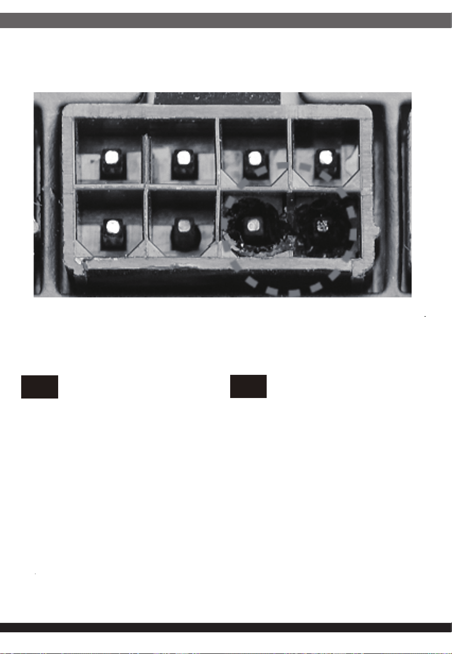
⚎њֱ䅋Փ⫼㗙ঞ䰆☿ⱘⳂⱘˈᅝ㺱ℸѸᓣ䳏⑤կឝ఼ᰖˈᖙ䷜ᅝ㺱ᮐヺড়ϟ߫䷙㽕∖ⱘ←Ёˈ
ϺϨᅝ㺱ཹᕠˈᠡৃϞ䳏⑤DŽ
←ᴤ䊾䷜⚎䰆☿←DŽᴤ䋼乏Ў䰆☿DŽ
←ⱘϞᮍঞو䙞П೧ᔶ䭟ᄨˈ᳔ܻᕥϡৃᮐPPDŽ
←ⱘϞᮍঞو䙞П䭋ṱൟ䭟ᄨˈᇡ㾦㎮䎱䲶ϡৃᮐPP˗㢹ᇀᑺᇣᮐPPˈࠛ䭋ᑺϡফ䰤ࠊDŽ
←ᑩ䚼ϡৃ᳝䭟ᄨDŽᑩ䚼ϡৃ᳝ᓔᄨDŽ
ⳈᕥϡᮐPP
ᇡ㾦㎮ϡᮐPP
ᇀᑺᇣᮐPPࠛ䭋ᑺϡ䰤
Openings that do not exceed 1mm in width regardless of length
Openings that do not exceed 5mm in any dimension
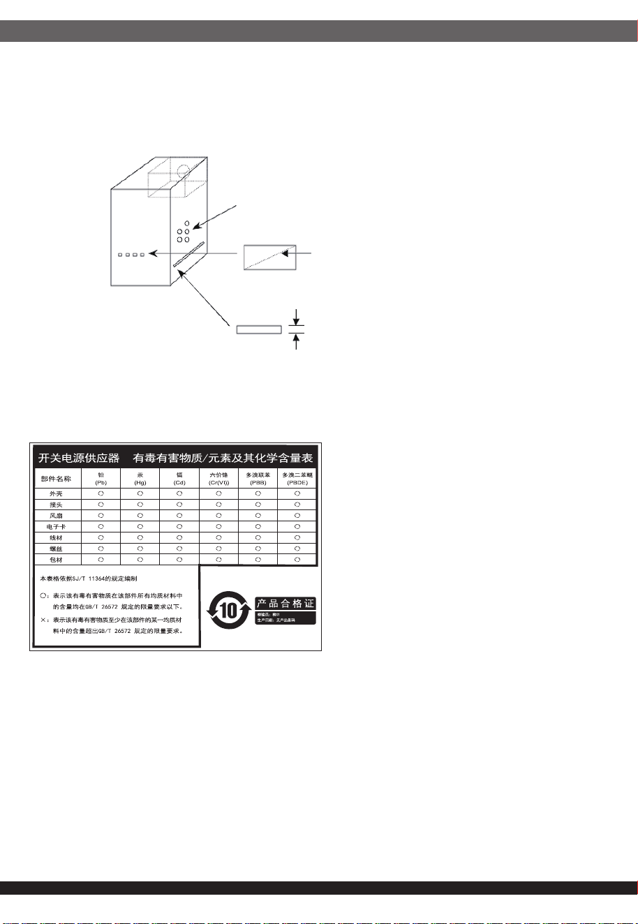
ᴀ⫶ક䔌ߎ᳝䱾㛑䞣ˈ⚎䙓ܡ᪡ᰖⱐ⫳䱾ˈ䷜ᮐ㺱ܹ㋏㍅″←Ϻᇛ᠔᳝䀁٭ᅝ㺱ཹ⭊ᕠᠡৃ䭟ଳ䳏⑤DŽ
ᴀ⫶કП䳏⑤䔌ߎ䴲ቀ䳏䰤ࠊൟ䳏⑤ˈ䂟䗷Փ⫼䰆☿←П䙞ˈҹ䙓ܡ☿♑䱾ⱐ⫳DŽ
%60,52+6䊛㿞
KWWSZZZVLOYHUVWRQHWHNFRPGRZQORDGV36856'SGI
This device complies with Part 15 of the
FCC Rules.Operation is subject to the
following two conditions:
(1) this device may not cause harmful
interference, and
(2) this device must accept any
interference received, including
interference that may cause
undesired operation.
Please refer to SilverStone website for latest specifications updates.
the power supply is only suitable for Information
Technology & Audio/Video equipment.
※付属の電源コードは当該製品専用です。他の機器に使用しないでください。
Model (safety certification) : SST-CS0800FCPT-A