SMC-IOM-SC102ZB-ST103ZB-2020.02v1_2020-02-10
Installation & Operation Manual
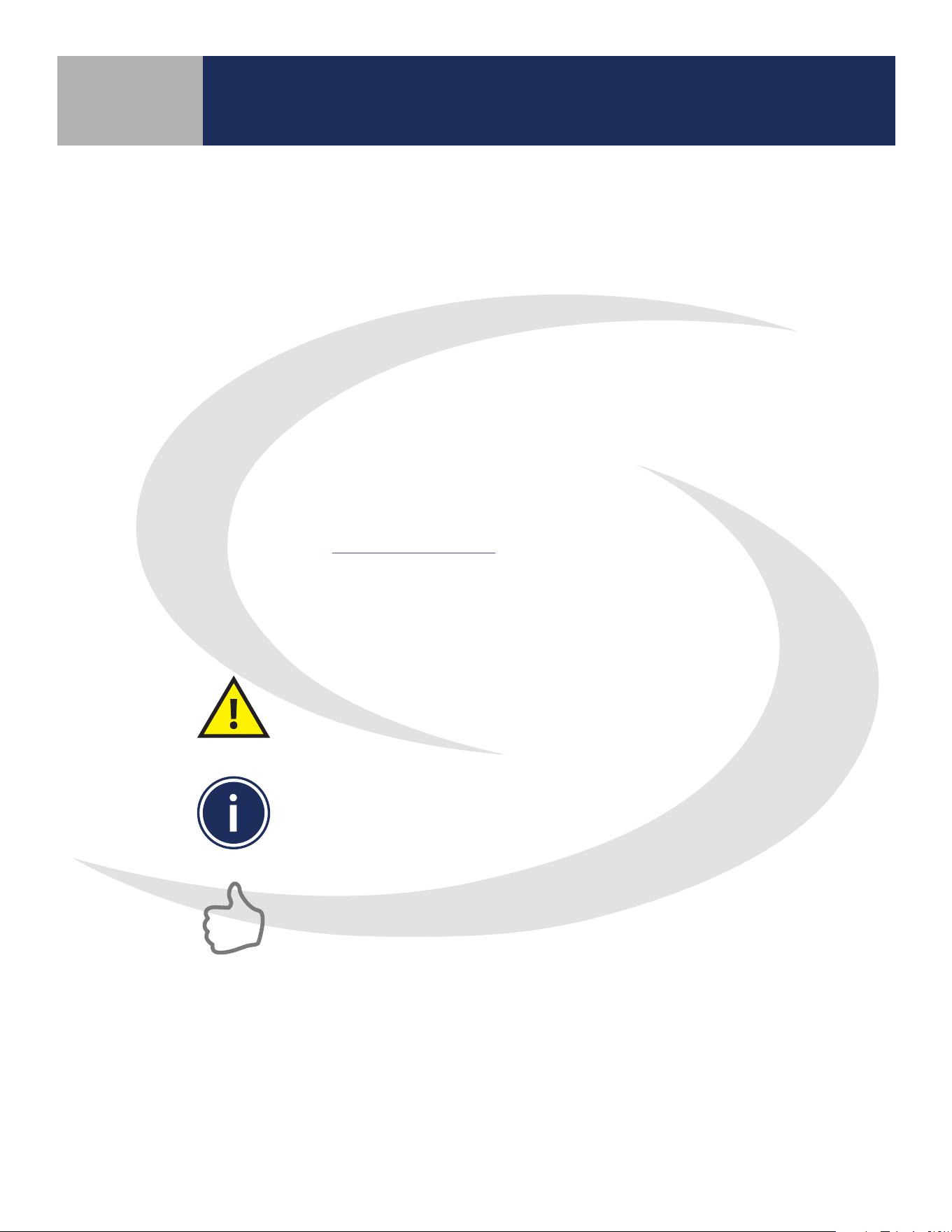
SC102ZB Fan Coil Controller
ST103 Wireless Fan Coil Remote

i
Section Page
1 Introduction
Why SALUS? .............................................................................................1-1
Using This Manual .......................................................................................1-1
System Overview ........................................................................................1-2
SALUS Smart Home Application ..........................................................................1-3
Product Safety Information ..............................................................................1-3
2 Included Parts/Tools
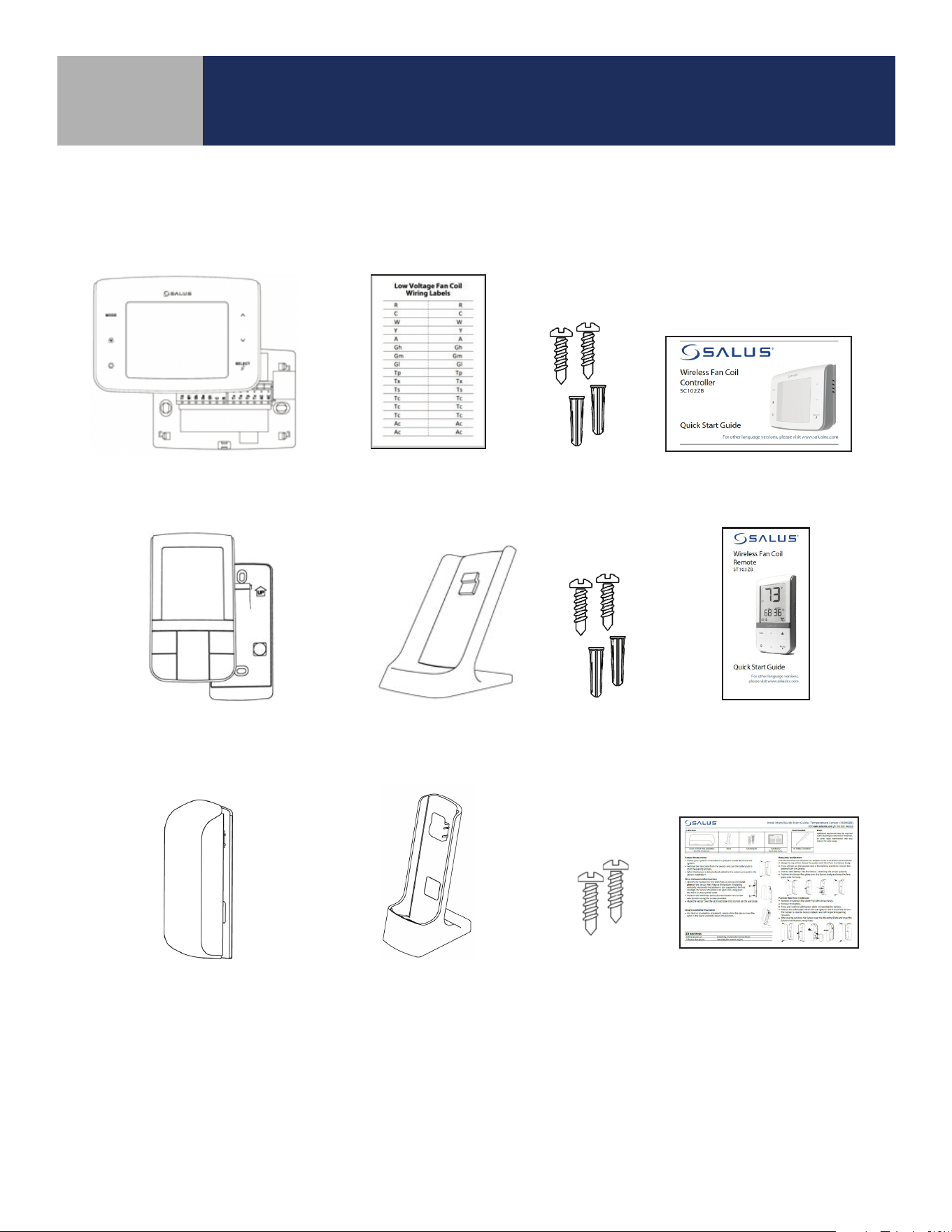
Included Parts – SC102ZB Fan Coil Controller .............................................................2-1
Included Parts – ST103ZB Wireless Fan Coil Remote . . . . . . . . . . . . . . . . . . . . . . . . . . . . . . . . . . . . . . . . . . . . . . . . . . . . . . . 2-1
Included Parts – SS909ZB Remote Temperature Sensor....................................................2-1
Tools (Required/Optional)................................................................................2-1
3 SC102ZB Fan Coil Controller Installation
Existing Wired Thermostat Removal ......................................................................3-1
SC102ZB Fan Coil Controller Installation . . . . . . . . . . . . . . . . . . . . . . . . . . . . . . . . . . . . . . . . . . . . . . . . . . . . . . . . . . . . . . . . . . 3-2
Optional External Antenna (Sold Separately) Installation ..................................................3-4
4 ST103ZB Wireless Fan Coil Remote Installation
Wall Plate Mounting .....................................................................................4-1
Desk Stand Mounting....................................................................................4-1
5 SS909ZB Remote Temperature Sensor Installation
Wall Plate Mounting .....................................................................................5-1
Desk Stand Mounting....................................................................................5-1
6 Fan Coil Controls – Keypad & Display
Keypad..................................................................................................6-1
Display Icons ............................................................................................6-1
7 Device Joining & Pairing
SC102ZB Fan Coil Controller – Preparation for Joining Network............................................7-1
ST103ZB Wireless Fan Coil Remote – Preparation for Joining Network......................................7-1
SS909ZB Remote Temperature Sensor – Preparation for Joining Network ..................................7-2
Pairing with SG888ZB Gateway & Internet Connection ....................................................7-3
Pairing without Internet Connection .....................................................................7-3
i
SC102ZB/ST103ZB Installation and Operation Manual
Contents

ii
Section Page
8 Thermostat Configuration
Settings Button Operation ...............................................................................8-1
Special Function Codes ..................................................................................8-4
9 Operation
Operating Modes ........................................................................................9-1
Programmable Thermostat (Standalone or Local Mode Only ..............................................9-2
Set Point Override .......................................................................................9-2
Heating/Cooling Modes..................................................................................9-2
Fan Modes ..............................................................................................9-3
P22 – Accessory Function ................................................................................9-4
P16 – AWAY Mode .......................................................................................9-5
10 Troubleshooting
Troubleshooting........................................................................................10-1
11 Installer Notes
Installer Notes ..........................................................................................11-1
Appendix A – Parameter List
Parameter List ...........................................................................................A-1
SC102ZB/ST103ZB Installation and Operation Manual
Contents
1-1
Why SALUS?
Salus designs and manufactures industry-leading hydronics, HVAC, and fan coil products
for heating engineers and contractors who need to drive protability and deliver customer
satisfaction. Through our proven, innovative products, we enable contractors to provide
homeowners and building managers with the comfort and control they need, while reducing
installation times and minimizing costly call-backs. Our easy-to-install wireless hydronic
controls, and patented, industry-rst auto-balancing actuators are advancing the industry.
Salus also oers a broad ecosystem of smart home products, including connected thermostats,
a smart home hub, smart plugs, water valve shuto, and door and window sensors. A proven
leader in the European market since 2003, Salus is currently expanding across North America.
Using this Manual
For the latest Instructions go to: WWW.SALUSINC.COM
Special Attention Boxes
This manual uses special attention icons to alert the reader of important safety concerns, information
important to reliable operation of the controls or helpful installation/setup information.
Safety:
Indicates a condition which may cause severe personal
injury, death or major property damage
Important Information:
Indicates information which requires special
attention for correct operation of the control
Your Benet:
Indicates helpful installation or setup information
Section 1
SC102ZB/ST103ZB Installation and Operation Manual
Introduction
1-2
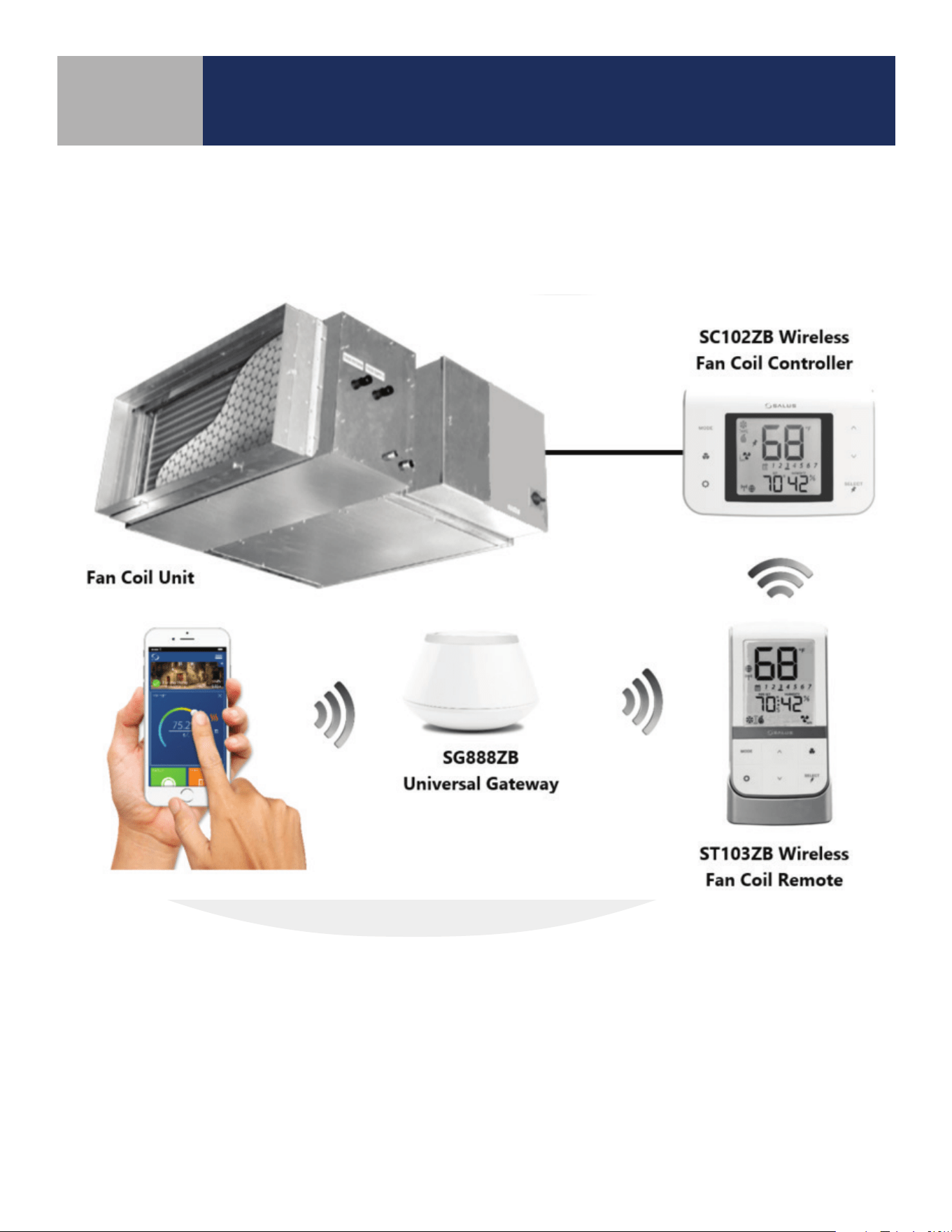
System Overview
SALUS connected Fan Coil control systems use Zigbee-based communications protocol to provide a
universal language for smart components to work together seamlessly and securely with an internet
connection.
By connecting the SG888ZB Gateway to your home network, the system is connected to the worldwide
web. Monitor or adjust your Fan Coil system from anywhere via the SALUS Smart Home application from
a smart device or computer. If the connection to the internet is lost, the system continues to function
with the settings selected.
Section 1
SC102ZB/ST103ZB Installation and Operation Manual
Introduction
1-3
Section 1
SC102ZB/ST103ZB Installation and Operation Manual
Introduction
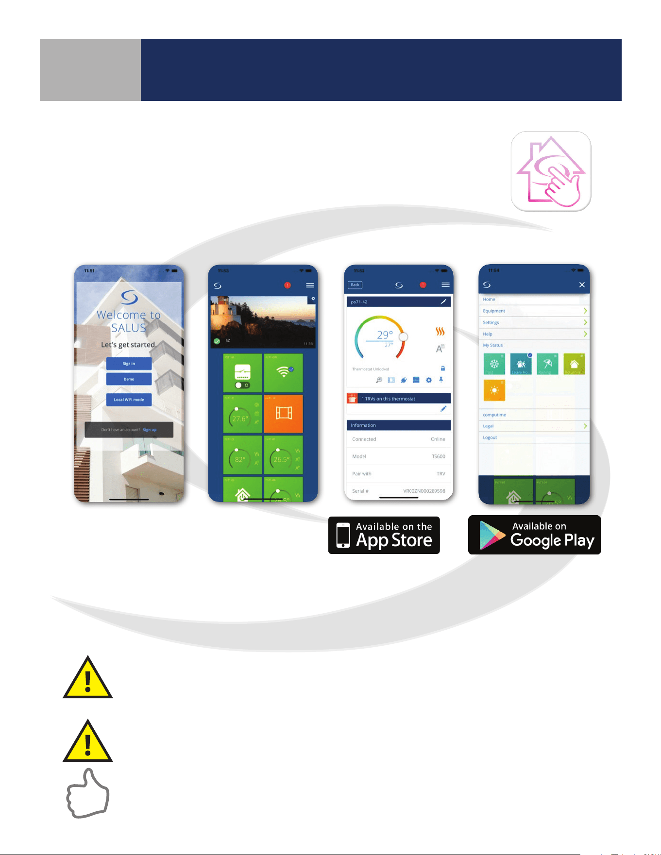
SALUS Smart Home Application
Use SALUS Smart Home to:
• Quickly view and monitor the status of your home and smart devices
• Set schedules and preferences for your connected thermostats, smart
plugs and more
• Receive important real-time alerts and notications of any changes
with your system
Download the SALUS Smart Home application on
your IOS or Android device for remote access to
your home comfort system. After downloading
the application, follow the steps in section 4.1.1
to create a user prole and set up an SG888ZB
Gateway.
Apple, the Apple logo, iPhone,
and iPod touch are trademarks of
Apple Inc, registered in the U.S.
and other countries. App Store is a
service mark of Apple Inc, registered
in the U.S. and other countries.
Codes & Regulations: Installation and setup of this product must be performed in strict
compliance with country, state/province and local regulating agencies and codes that
deal with Class B digital devices. In the absence of local requirements, the FCC rules, listed
below, are to be followed.
Intended Use: The SALUS SC102ZB Wireless Fan Coil Controller and ST103ZB Wireless
Fan Coil Remote are intended for interior room temperature control in conjunction with
hydronic fan coil heating systems only. Other uses are not recommended or supported.
Installer or Contractor: Record parameters at startup and any subsequent parameter
changes in the installer notes section of this manual.
Product Safety Information
Google Play and the Google Play logo
are trademarks of Google LLC
Section 2
SC102ZB/ST103ZB Installation and Operation Manual
Included Parts/Tools
Review Parts
Be sure that all parts listed for each device are included and available before start installation.
SC102ZB Wireless Fan Coil Controller
Required Tools
• #1 Phillips or athead screwdriver • 3/16” drill bit & drill (if anchors are required)
Optional Tools (for SC102ZB)
• Smartphone or digital camera for wiring reference photos
• Small screwdriver for removing wiring from old thermostat terminals
• Pencil for holding wires in place during installation
2-1
Wiring Labels
Screws and
Anchors
Controller with Wiring Mount
Installation/
Quick Start Guide
Desk Stand Screws and
Anchors
Remote with Batteries
and Wall Mount
Installation/
Quick Start Guide
ST103ZB Wireless Fan Coil Remote
SS909ZB Remote Temperature Sensor
Stand Mounting
Kit
Temperature Sensor with
Battery and Wall Plate
Installation/
Quick Start Guide
3-1
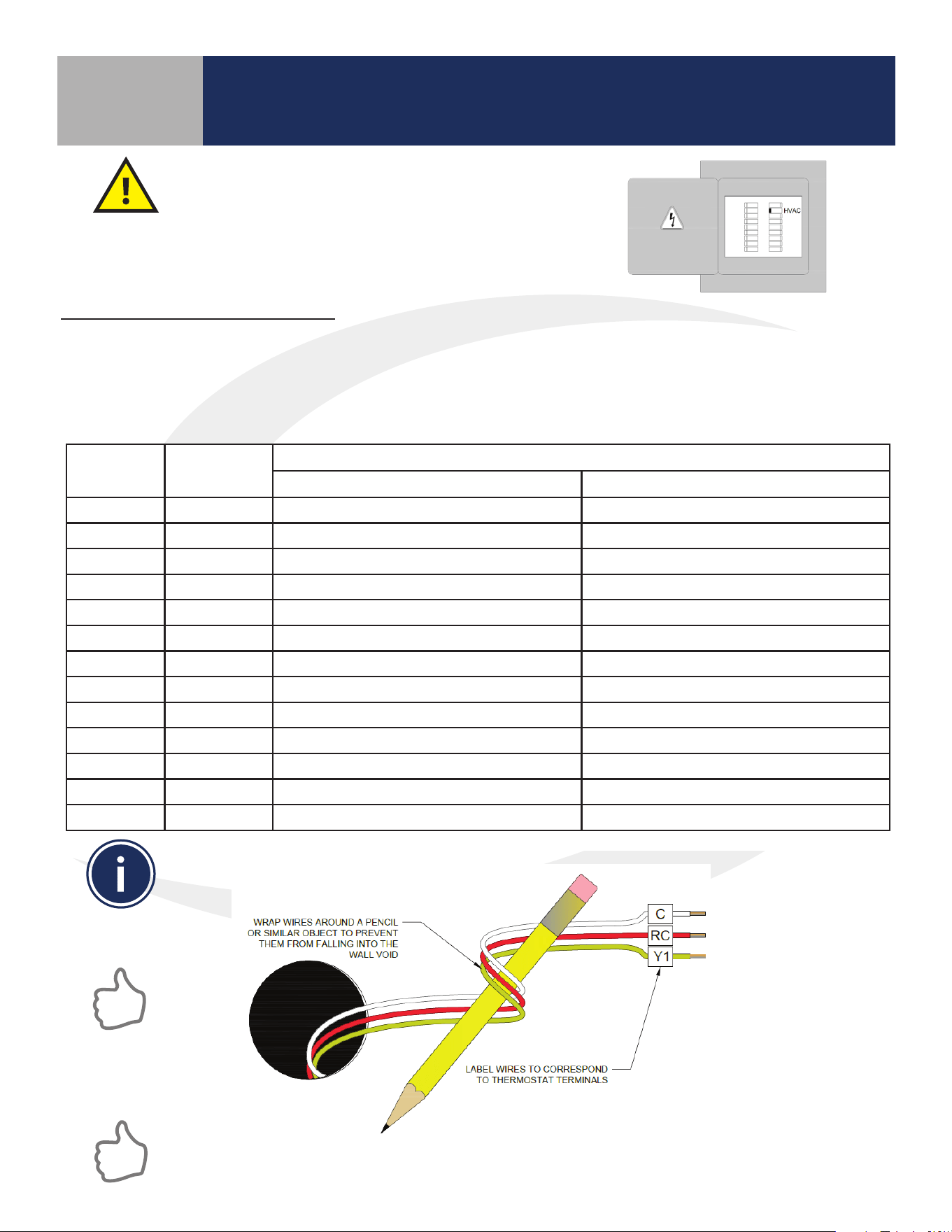
Existing Wired Thermostat Removal
Use the following procedure to review and record the wiring conguration
before disconnecting an existing wired thermostat.
Before beginning the installation procedure, turn
o power to the fan coil system.
Section 3
SC102ZB/ST103ZB Installation and Operation Manual
SC102ZB Fan Coil Controller Installation
If replacing an existing wired thermostat, review and record the wiring conguration of the existing
thermostat:
• Remove existing thermostat from the wall to expose the wiring terminals
• Take a photograph or note the wire colors and connections (see Table 3.1 below)
• Attach wire labels to each of the wires
Table 3.1: Wire Designation Record
Terminal Wire Color
Function
4 Pipe System 2 Pipe System
R 24 VAC Input 24 VAC Input
C 24 VAC Common 24 VAC Common
Gl Fan – Low Speed Fan – Low Speed
Gm Fan – Medium Speed Fan – Medium Speed
Gh Fan – High Speed Fan – High Speed
WY Heat Supply Valve Actuator Heat/Cool Supply Valve Actuator
YA Cooling Supply Valve Actuator Auxiliary Heat
Ac Accessory Contact Accessory Contact
Ac Accessory Contact Accessory Contact
Tp Supply Pipe Temp. Sensor Supply Pipe Temp. Sensor
Tx External Temp Sensor (wired) External Temp Sensor (wired)
Ts Temperature Setback Temperature Setback
Tc Tx/Tp/Ts Common Tx/Tp/Ts Common
After labeling the wires, disconnect them from the thermostat terminals and remove the
thermostat mounting plate (if necessary).
Paint the mounting surface, if desired, before mounting the new thermostat back plate to ensure
complete wall coverage.
3-2
SC102ZB Fan Coil Controller Installation
Section 3
SC102ZB/ST103ZB Installation and Operation Manual
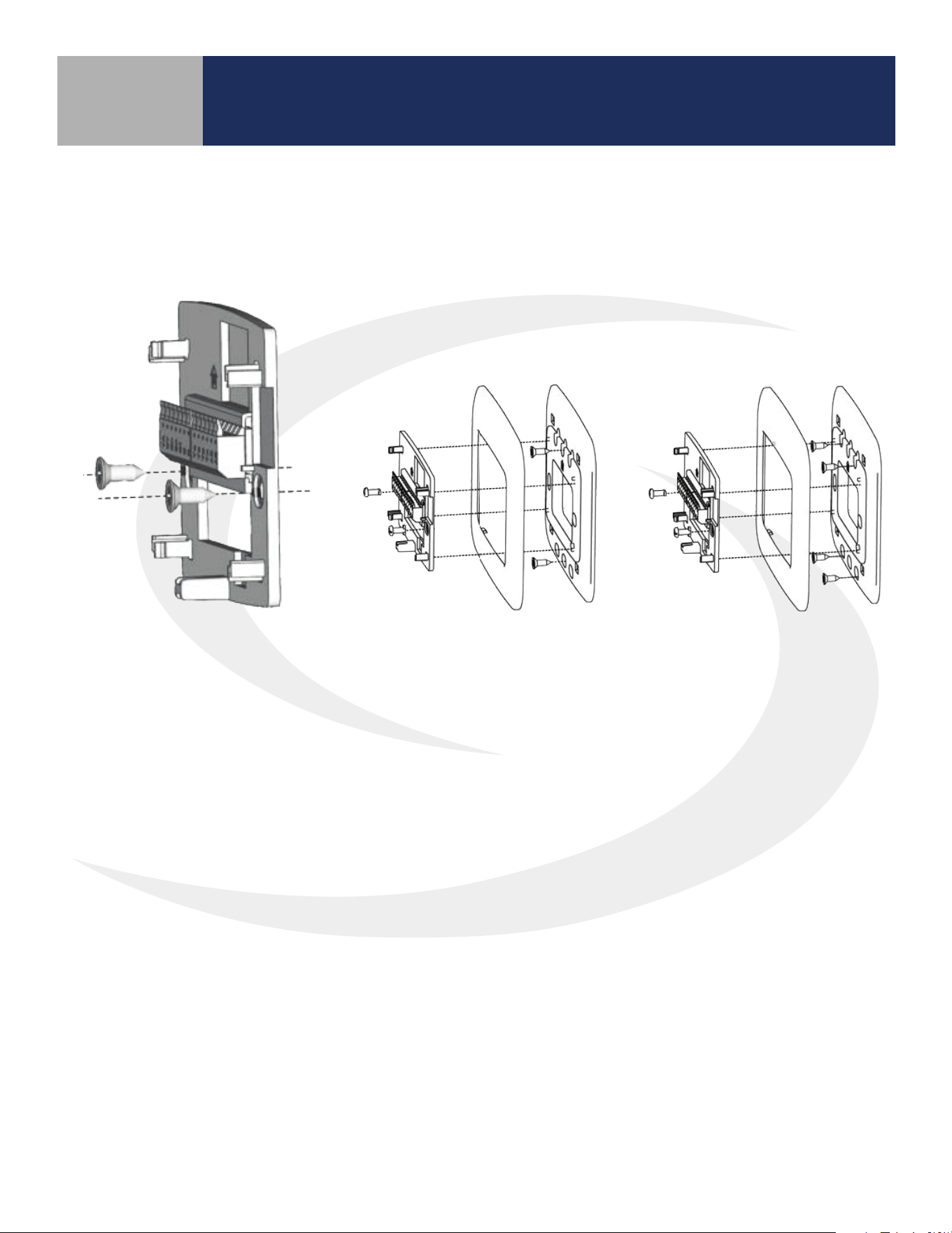
SC102ZB Fan Coil Controller Installation
No Junction Box or
Horizontal 2” x 4” Box
Vertical 2” x 4” Junction Box
(wall plate sold separately)
4” x 4” Junction Box
(wall plate sold separately)
Install the Wiring Mount in the desired location using the wall screws provided, making sure the
wires go through the center opening. Anchors are provided if necessary. An optional wall plate
(sold separately) is available for mounting to a junction box (see below).
3-3
Section 3
SC102ZB/ST103ZB Installation and Operation Manual
SC102ZB Fan Coil Controller Installation
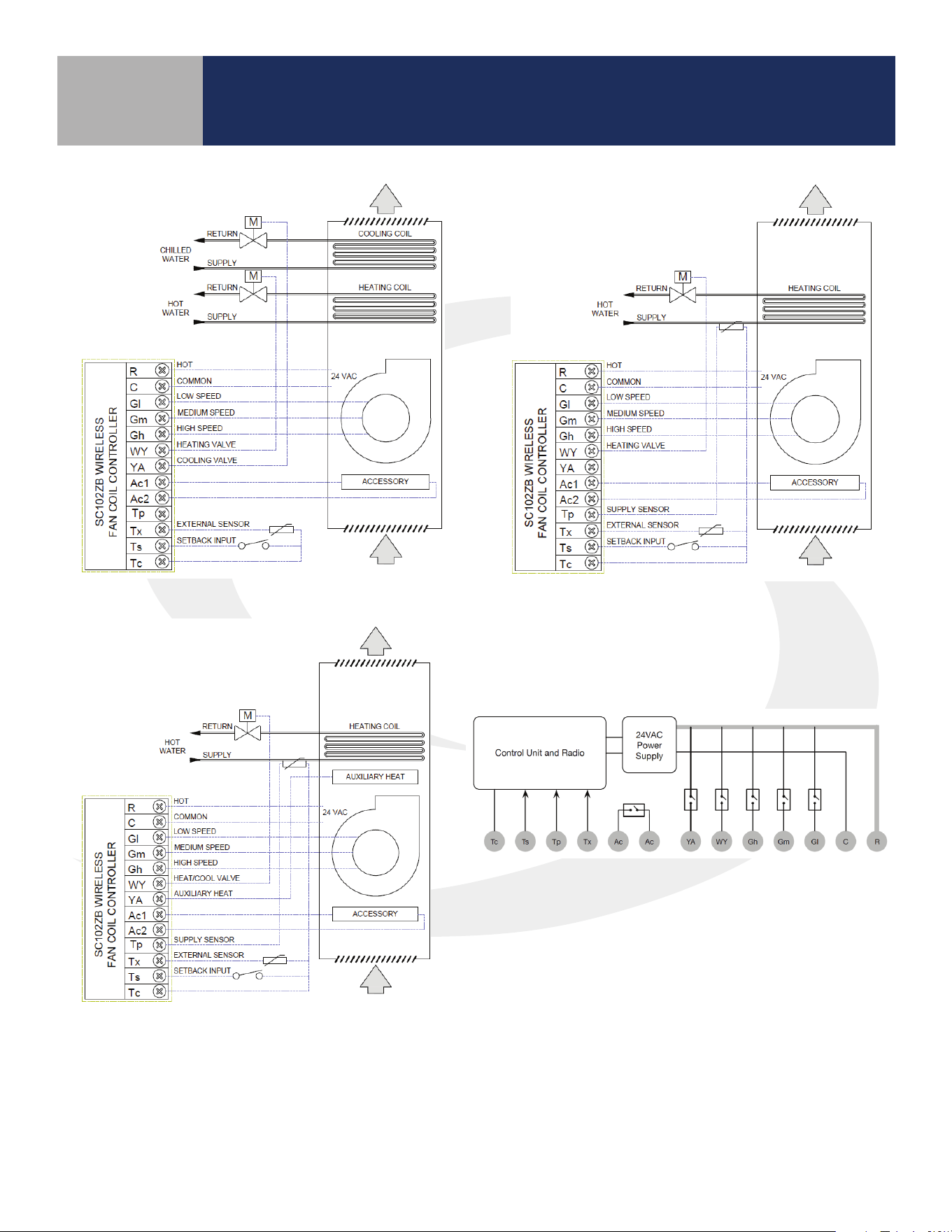
SC102ZB Internal Block Diagram
SC102ZB
2-Pipe Application
SC102ZB 4-Pipe Application
SC102ZB
2-Pipe Auxiliary Heat
Application
3-4
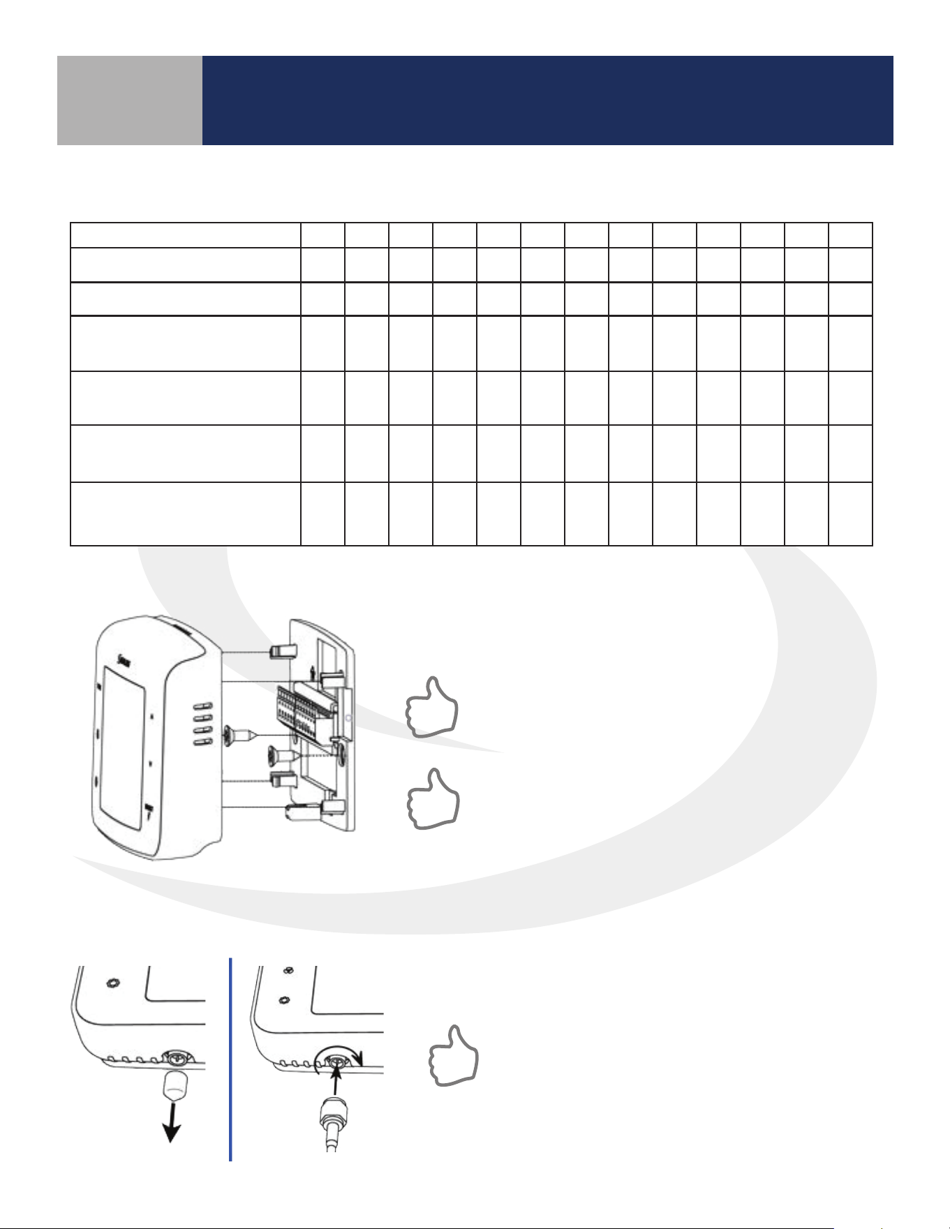
Connect Wiring to the SC102ZB Back Plate – Use table 3.2 below to identify the desired conguration
Table 3.2: Wiring Configuration Checklist
Section 3
SC102ZB/ST103ZB Installation and Operation Manual
SC102ZB Fan Coil Controller Installation
Configuration R C Gl Gm Gh WY YA Ac Ac Tp Tx Ts Tc*
2-Pipe Heat Only
W o o o o o o
2-Pipe Cool Only
Y o o o o o o
2-Pipe Heat/Cool
Manual Changeover
W/Y o o o o o o
2-Pipe Heat/Cool
Seasonal Changeover
W/Y o o
o o
2-Pipe Heat/Cool
w/Auxiliary Heat
W/Y A o o
o o
4-Pipe Heat/Cool w/Manual
or Auto Changeover
W Y o o o o o
=Required / o=Optional / W=Heat Valve Actuator / Y=Cool Valve Actuator / A=Auxiliary Heat
* If using more than one (Tp/Tx/Ts) terminal, it may be necessary to splice Tc.
Attach controller to the wiring mount by aligning the
connector pins.
Make sure the connector pins are not bent and that
the controller is fully seated on the wiring mount.
If an external antenna (sold separately) is required
due to insucient radio coverage, attach the
antenna, as follows, before attaching the controller
to the wiring mount
Optional External Antenna (Sold Separately)
Use the ANT10RF External Antenna if there is insufficient radio signal at the ST103ZB Wireless
Remote or SS909ZB Remote Temperature Sensor.
Remove the antenna connector cover located on the bottom
of the SC102ZB Fan Coil Controller.
Avoid locations that place large metal enclosures,
piping or dense electrical wires between the
SC102ZB Fan Coil Controller and the ST103ZB
Wireless Fan Coil Remote.
Attach the external antenna to the connector, making sure
the nut is nger tight. DO NOT OVERTIGHTEN the nut.
4-1
ST103ZB Wireless Fan Coil Remote Installation
The ST103ZB Wireless Fan Coil Remote acts as a remote thermostat which can be wall mounted
or placed in a stand for desk or cabinet top operation. The Wireless Remote can be paired prior to
mounting (see Section 5, Pairing Instructions for details). For desk top operation, the ST103ZB can
be moved to a dierent location at any time.
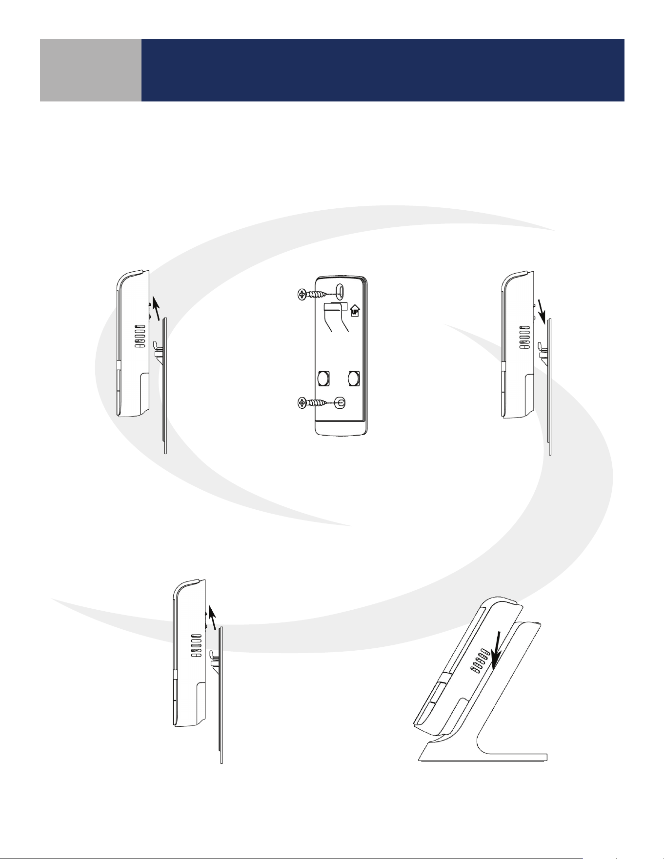
Wall Plate Mounting
Desk or Cabinet Top Mounting
Remove the Wall Mount
from the back of the
ST103ZB Wireless Fan Coil
Remote.
Attach the Wall Mount in
the desired location using
the screws and anchors
provided.
Slip the ST103ZB Wireless
Fan Coil Remote onto the
Wall Mount.
Remove the Wall Mount from the back
of the ST103ZB Wireless Fan Coil Remote.
Slip the ST103ZB Wireless Fan Coil
Remote onto the Desk Stand.
Section 4
SC102ZB/ST103ZB Installation and Operation Manual
ST103ZB Wireless Fan Coil Remote Installation
5-1
Section 5
SC102ZB/ST103ZB Installation and Operation Manual
SS909ZB Remote Temperature Sensor Installation
The SS909ZB Remote Temperature Sensor is OPTIONAL and not required for
all installations.
The SS909ZB Remote Temperature Sensor provides additional temperature input for your Wireless Fan
Coil System. Multiple SS909ZB Sensors can be connected to allow temperature averaging throughout
the conditioned space. Remote Temperature Sensors can be permanently mounted on a wall mounted
or mounted on a stand for desk or cabinet top operation. The Remote Temperature Sensor can be
paired prior to mounting (see Section 7, Device Joining & Pairing for details). For desk top operation,
the SS909ZB Sensors can be moved to dierent locations at any time.
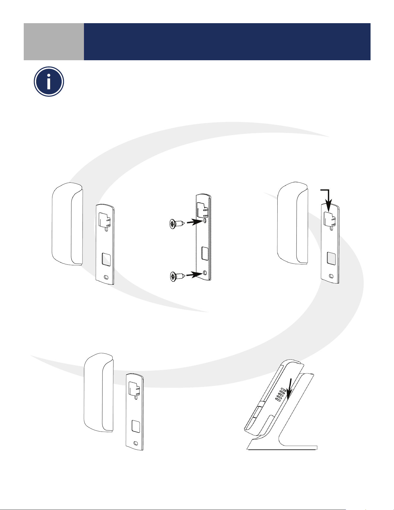
Wall Plate Mounting
Desk Top Mounting
Remove the Wall Plate from
the back of the SS909ZB
Remote Temperature Sensor.
Attach the Wall Mount in
the desired location using
the screws and anchors
provided.
Slip the SS909ZB Remote
Temperature Sensor onto
the Wall Mount.
Remove the Wall Plate from the back of
the SS909ZB Remote Temperature Sensor.
Slip the SS909ZB Remote Temperature
Sensor onto the Desk Mount.
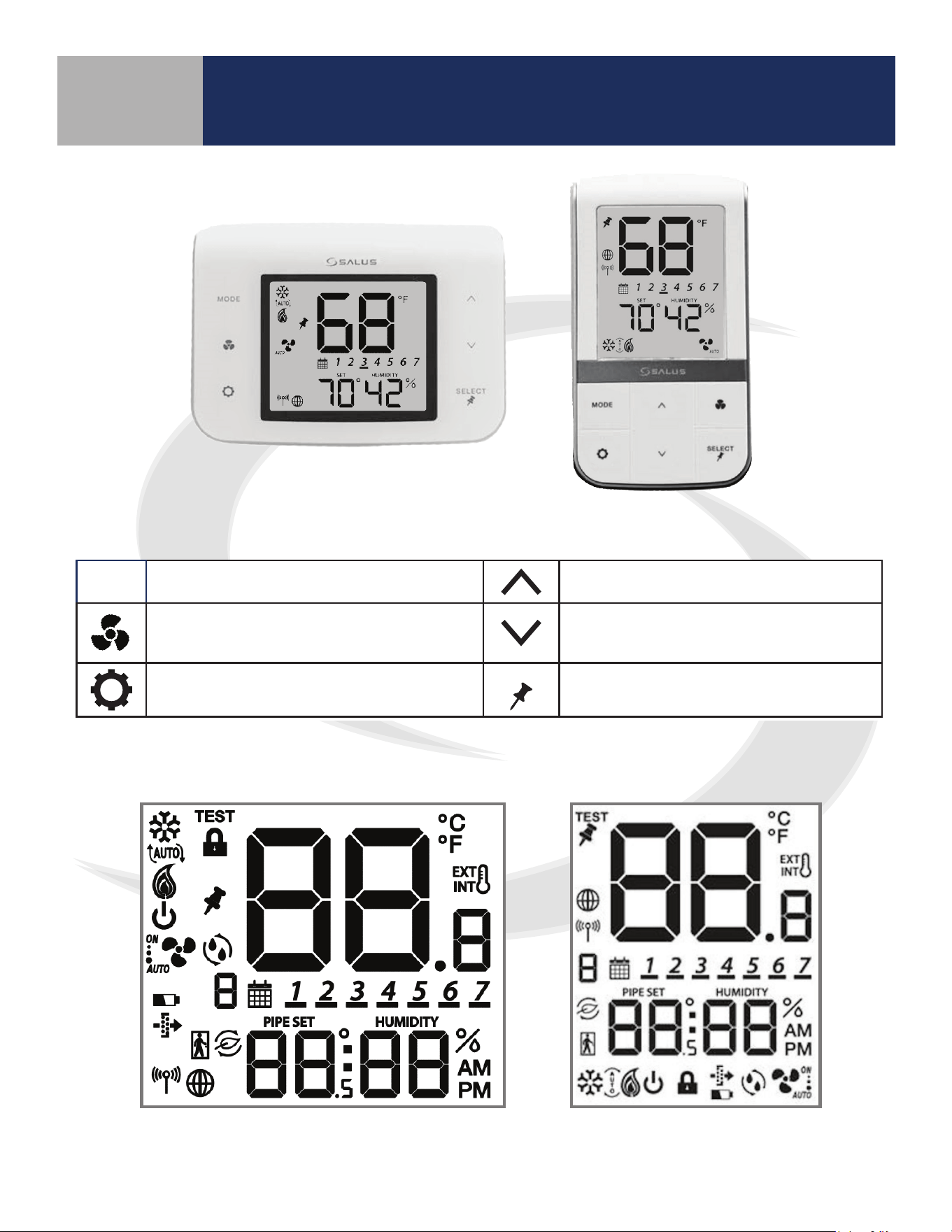
6-1
Section 6
SC102ZB/ST103ZB Installation and Operation Manual
Device Controls – Keypad & Display
Keypad
MODE
Heat, Cool, Auto, Off selection Increase Value
Fan On/Auto, Low Speed, Medium
Speed, or High Speed
Decrease Value
Enter/Exit Settings mode
SELECT
Confirm/Change Display Mode/Acti-
vate Permanent Hold
Display Icons
SC102ZB
ST103ZB
Table 6.1: Keypad Functions
SC102ZB ST103ZB
6-2
Section 6
SC102ZB/ST103ZB Installation and Operation Manual
Device Controls – Keypad & Display
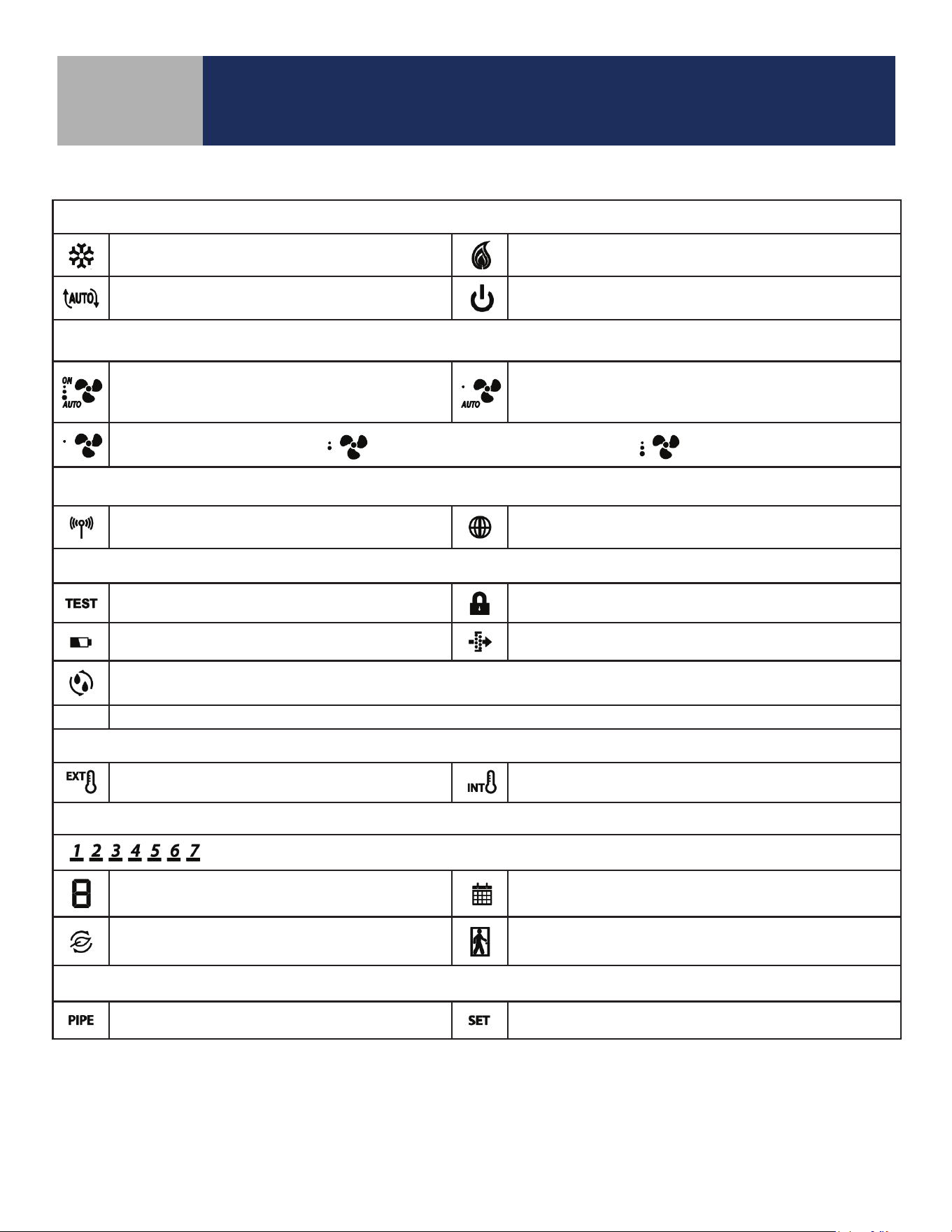
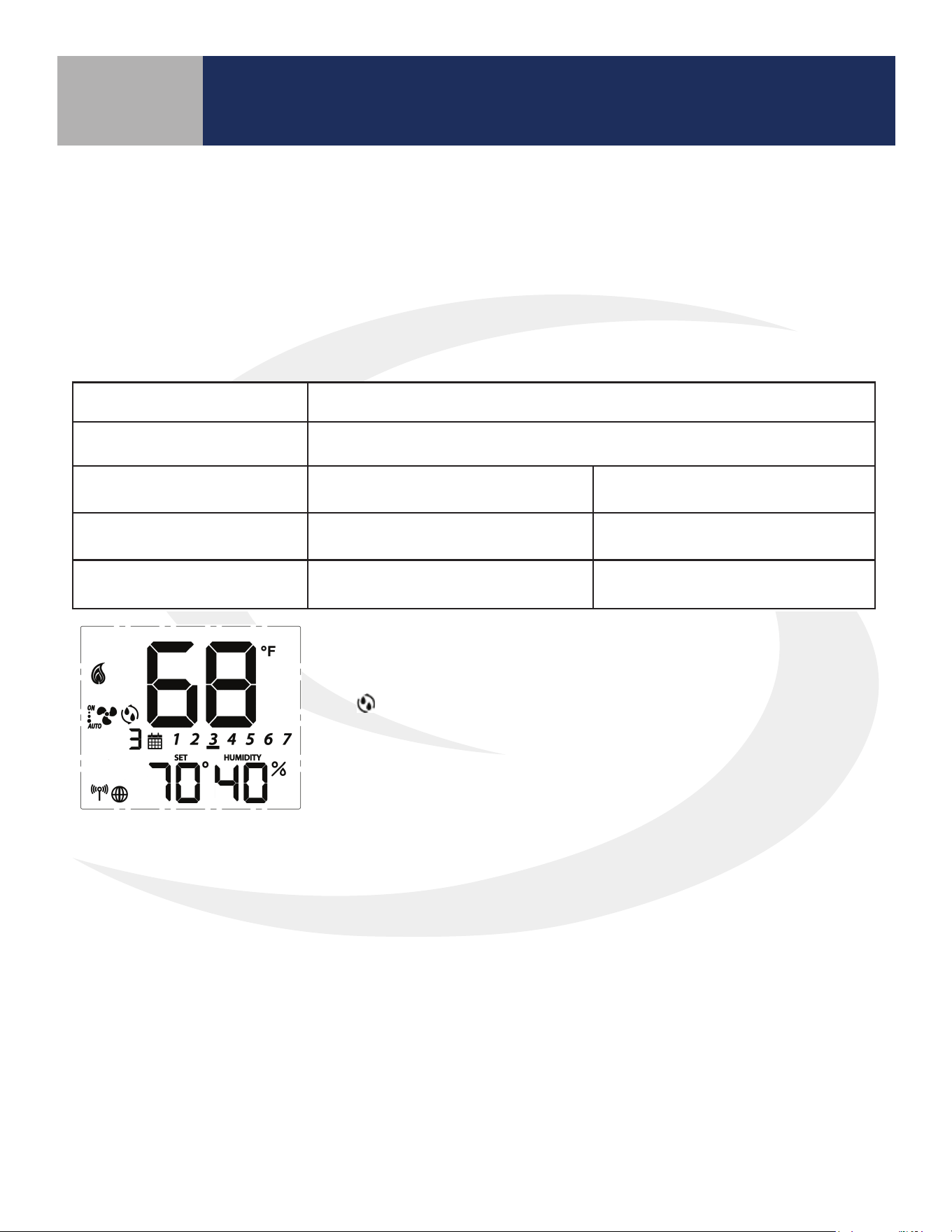
Heat/Cool/Off Modes
Cooling (Animated when cooling is on)
Heating (Animated when heat is on)
Auto Heat/Cool Changeover
Off
Fan Modes
ON – Indicates Constant Fan Enabled
3 Dots – High Speed
AUTO – Automatic Fan Speed
– Constant Fan Disabled
1 Dot – Low Speed
AUTO – Automatic Fan Speed
Fixed Fan Speed – Low Fixed Fan Speed – Medium Fixed Fan Speed – High
Wireless/Internet Indications
Device connected to local network Device connected to SALUS Smart Home Service
Test/Key Lock/Battery/Filter
Test Mode (Special Code 22) Keys Locked Mode
Battery Low (ST103 Wireless Remote Only) Change Filter (Timer expired)
Accessory Output On (Humidifier, Dehumidifier, ERV or HRV)
Internal/External Temperature Sensor
External Sensor Indication (wired or wireless)
Internal Sensor Indication (Only visible in TEST Mode)
Schedule Indications
Day of the week (Mon = 1, Tue = 2, Wed = 3, Thu = 4, Fri = 5, Sat = 6, Sun = 7)
Schedule Interval (1-6) - Specifies time interval
of scheduled temperature changes
Schedule Indicator – When shown, the Thermostat is
following a schedule
Setback Indicator – Setback input is activated
AWAY State Indicator – Displayed when the Fan Coil
Thermostat is set to AWAY, using setback temperatures
Multifunction Temperature Indication
Pipe temperature reading shown Setpoint temperature reading shown
Table 6.2: Display Icons
7-1
Section 7
SC102ZB/ST103ZB Installation and Operation Manual
Device Joining & Pairing
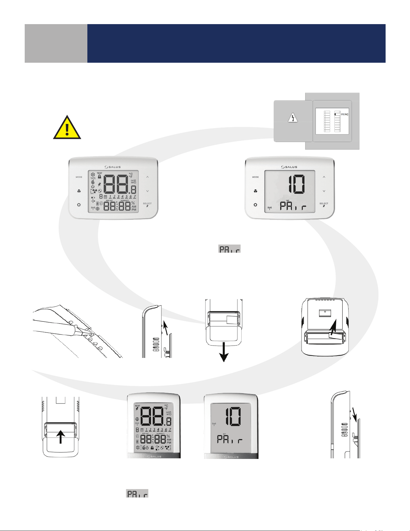
SC102ZB Fan Coil Controller
Preparation for Joining Network
After installing the SC102ZB Fan Coil Controller, the
ST103ZB Wireless Fan Coil Remote and any optional
SS909ZB Remote Temperature Sensors, turn on
electrical power to the fan coil system and SC102ZB
Fan Coil Controller.
When the SC102ZB Fan Coil Controller
is rst powered, all xed segments will
bebriey displayed. The display will
then show the rmware version.
If the Fan Coil Controller is not connected
to a network, the devices will display
and a countdown timer will start.
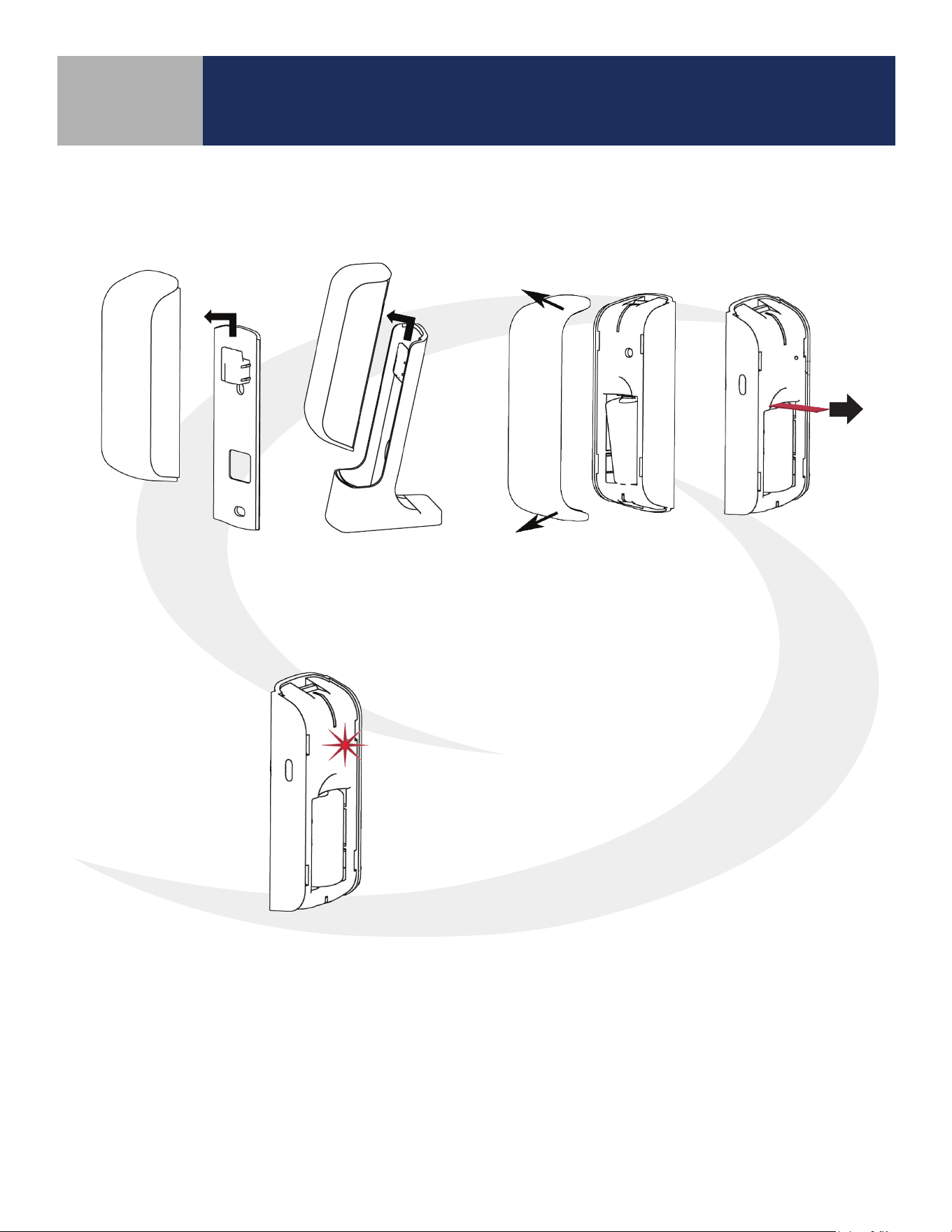
ST103ZB Wireless Fan Coil Remote
Preparation for Joining Network
Open the battery
compartment
Remove the ST103ZB Wireless Fan Coil
Remote from the Wall Plate or Desk Stand.
Remove the battery tab to power
the Wireless Fan Coil Remote
The screen will briey display all xed segments before
showing the rmware version. If the ST103ZB Wireless Fan
Coil Remote is not connected to a network, the device will
display
and a countdown timer will start.
Close the battery
compartment
Re-attach the ST103ZB
Remote to the Wall
Plate or Desk Stand
7-2
Section 7
SC102ZB/ST103ZB Installation and Operation Manual
Device Joining & Pairing
SS909ZB Remote Temperature Sensor
Preparation for Joining Network
When the battery tab is removed,
the red LED will begin to ash.
Remove the SS909ZB Remote Temperature
Sensor from the Wall Plate or Desk Stand.
Use a small screwdriver to remove the face
plate from the Remote Temperature Sensor
and pull the battery tab.
7-3
Section 7
SC102ZB/ST103ZB Installation and Operation Manual
Device Joining & Pairing
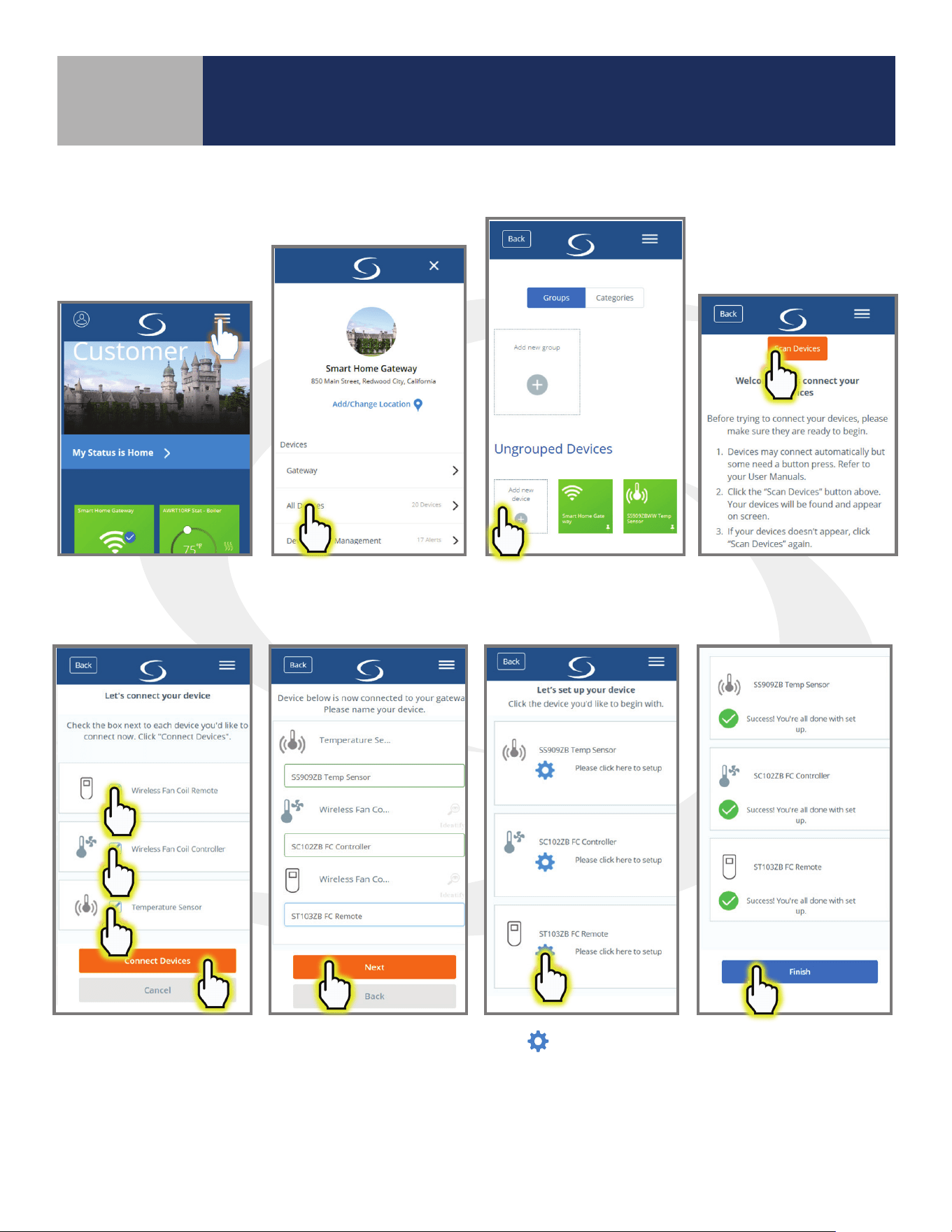
Pairing with SG888ZB Gateway and Internet Connection
Open the SALUS Smart Home application, select the drop-down menu from the upper right of the screen
and select: Settings
Devices Add New Equipment Scan for New Equipment
Check all devices to be
connected and press
“Connect equipment”.
Enter a unique name
for each device and
press “Next”
Press
to congure the
ST103ZB Fan Coil Remote.
Setup Automations
and Pin Settings. Once
complete, press “Finish”.
7-4
Section 7
SC102ZB/ST103ZB Installation and Operation Manual
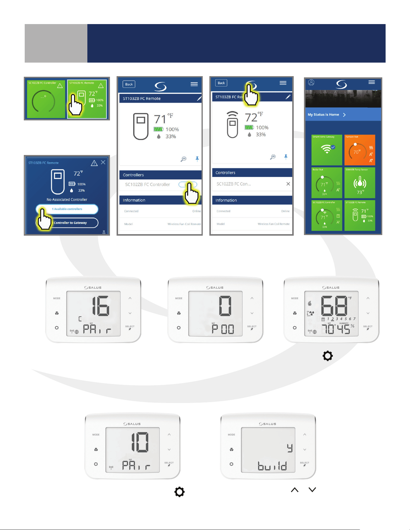
Device Joining & Pairing
To link the ST103ZB
Remote, choose the
tile icon.
Choose the Link button
corresponding to the
desired controller
When the Controller is linked, return to the
dashboard by pressing the SALUS Logo.
When the tile ips on
the screen, choose “#
available controllers”.
Pairing without an Internet Connection
Next, the SC102ZB Fan Coil
Controller enters Parameter
Setup.
Press the
key to enter
the operation screen.
Once the SC102ZB Fan Coil Controller
is successfully paired with a gateway,
the device will briey display the
Zigbee channel.
From the pairing screen press
.
Conrm build using
or ,
and press “SELECT”.
7-5
Section 7
SC102ZB/ST103ZB Installation and Operation Manual
Device Joining & Pairing
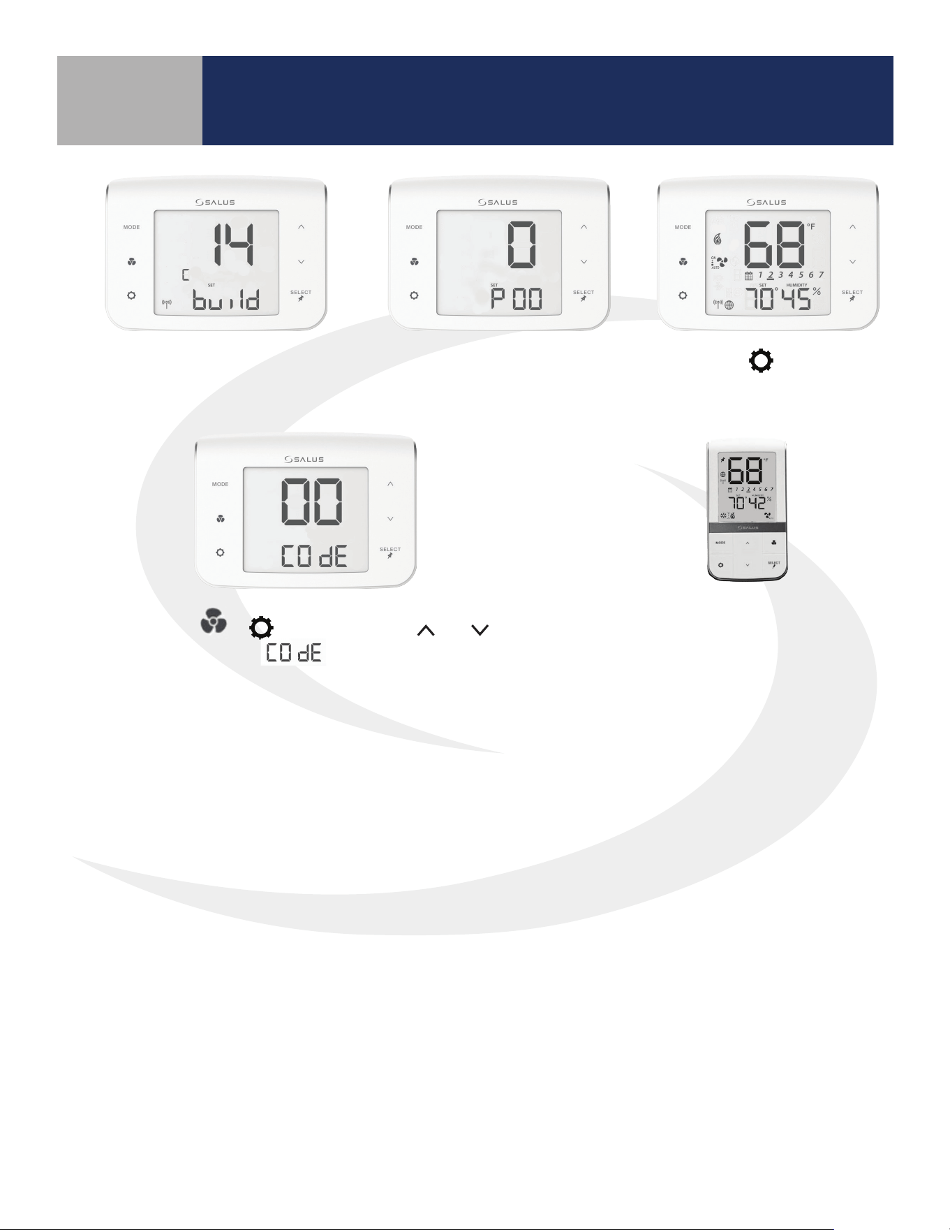
Next, the SC102ZB Fan Coil
Controller enters Parameter
Setup.
Press the
key to enter
the operation screen.
Once network building is complete,
the controller will display the radio
channel number being used.
Press MODE +
+ keys
simultaneously to enter
functions.
After pulling the battery tab on the
ST103ZB Fan Coil Remote, it will
automatically pair with the SC102ZB.
Use the
and keys
to set digits to “00”.
8-1
Section 8
SC102ZB/ST103ZB Installation and Operation Manual
Thermostat Configuration
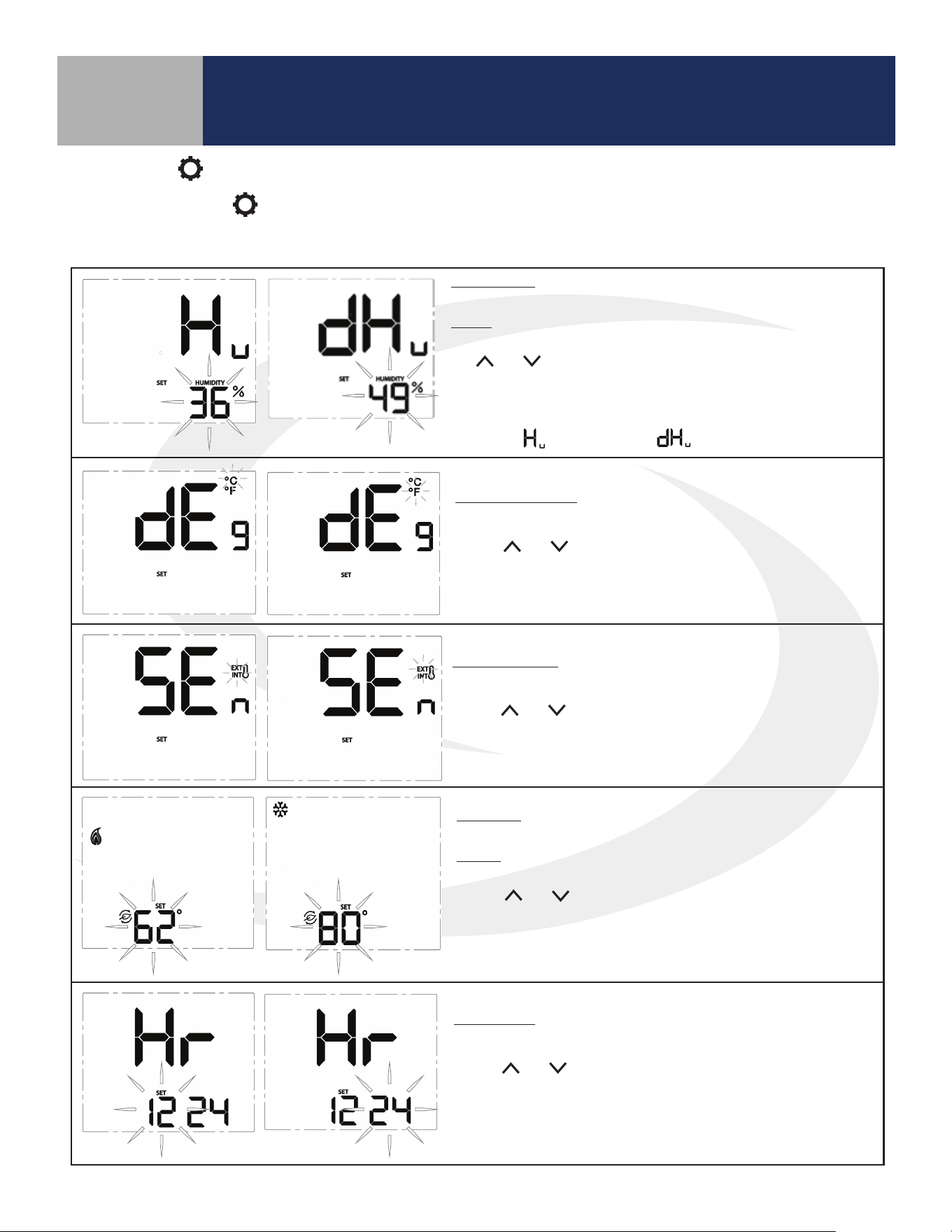
* Humidity: This setting allows users to adjust the relative
humidity setpoint.
Range: Humidifier – 20% to 50%
Dehumidifier – 40% to 80%
The and keys adjust the flashing relative humidity setpoint.
Press SELECT to choose the displayed value and move to the next
setting.
* This setting is only available if the accessory parameter (P22) is set to
Humidifier (
) or Dehumidifier ( ).
Temperature Units: Use this setting to choose between SI Metric and
US Customary temperature units.
Use the
and keys to toggle between °C and °F. Press
SELECT to choose the flashing value and move to the next
setting.
Sensor Location: Use this setting to choose between internal (INT)
and external (EXT) sensor location.
Use the
and keys to toggle between INT and EXT. Press SELECT
to choose the flashing value and move to the next setting (If INT is
chosen, INT will not be displayed on the home screen).
* Setback: Use this setting to choose a setback temperature for heat-
ing and/or cooling.
Range: Heat – 50-68°F (10-20°C)
Cooling – 73-90°F (23-32°C)
Use the and keys to change the setback temperature. Press
SELECT to choose the flashing value and move to the next setting.
* This setting is only available if the setback input parameter (P16) is
enabled.
Clock Format: This setting is used to change the clock format be-
tween 12 hour with am/pm and 24 hour.
Use the
and keys to toggle between 12 and 24 hour clock.
Press SELECT to choose the value displayed and move on to the next
setting.
Settings Button Operation
Pressing the SETTINGS button will allow adjustment of user selectable settings. Table 8.1 lists the available
settings and their functions.
Table 8.1: Thermostat Settings
8-2
Table 8.1: Thermostat Settings (continued)
Section 8
SC102ZB/ST103ZB Installation and Operation Manual
Thermostat Configuration
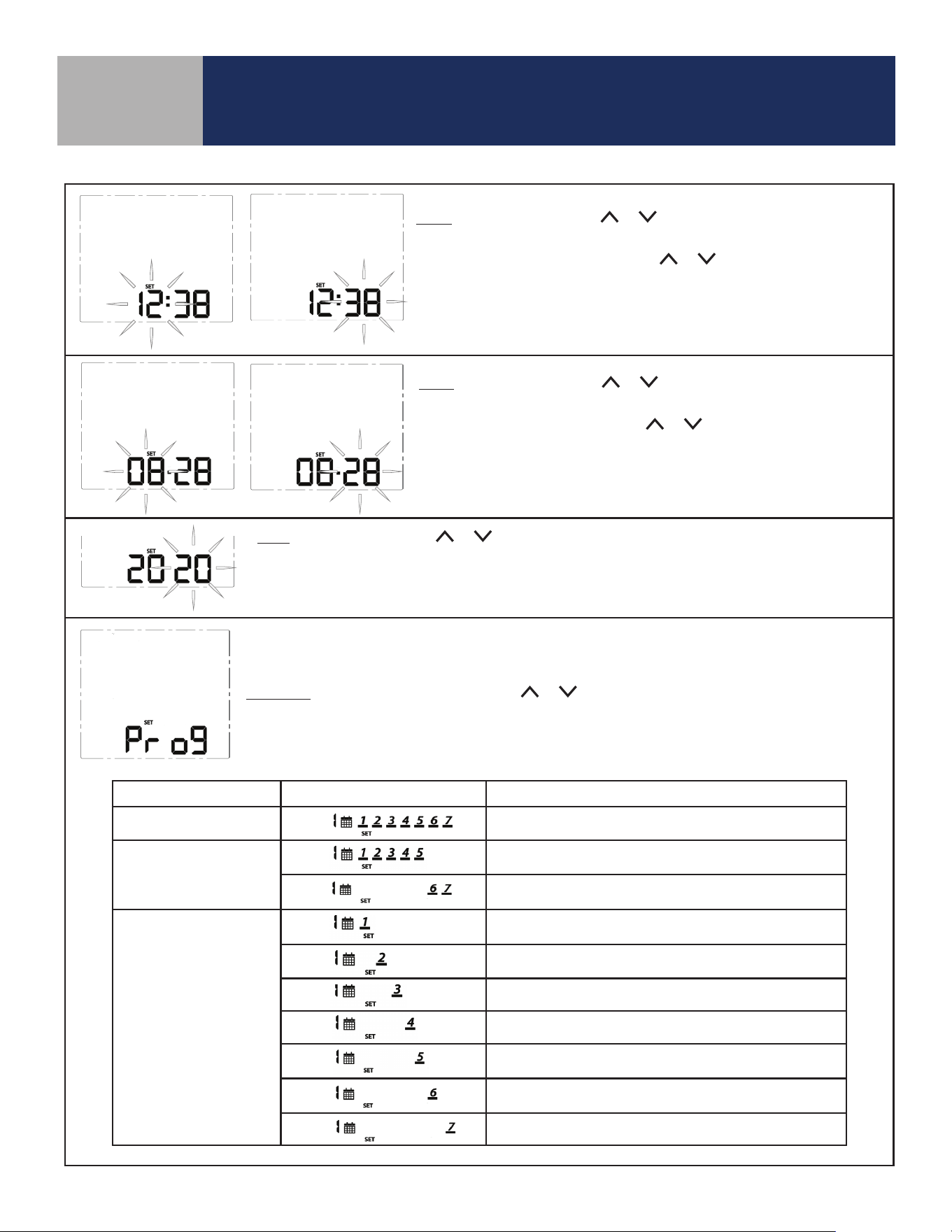
Time: To set the time, use the or keys to change the flashing hour
value, then press SELECT to choose the value displayed and select minutes.
With the minute value flashing, use the or keys to change the value.
Press SELECT to choose the value displayed and move to the next setting.
Note: This setting is available in standalone or local mode only.
Date: To set the date, use the or keys to change the flashing month
value, then press SELECT to choose the value displayed and select date.
With the date value flashing, use the or keys to change the value.
Press SELECT to choose the value displayed and move to the next setting.
Note: This setting is available in standalone or local mode only.
Year: To set the year, use the or keys to change the flashing year value.
Press SELECT to choose the value displayed and move to the next setting.
Note: This setting is available in standalone or local mode only.
Note: Schedule parameters are only available in standalone or local mode. If the Fan Coil Thermostat
is connected to the SALUS Smart Home application, the schedule must be programmed on your PC or
smart device.
Schedule: While Prog is displayed, press the or keys to change the day group to be edited.
See the following table that describes which days are programmed based on the display.
After selecting the day group, press SELECT to move to setting temperatures for each interval during
the day.
Program Mode Day Group Displayed Schedule Description
Weekly
Every day of the week
5+2
Weekdays/Weekend
(Default)
Monday through Friday
Saturday and Sunday
Daily
Monday
Tuesday
Wednesday
Thursday
Friday
Saturday
Sunday
8-3
Section 8
SC102ZB/ST103ZB Installation and Operation Manual
Thermostat Configuration
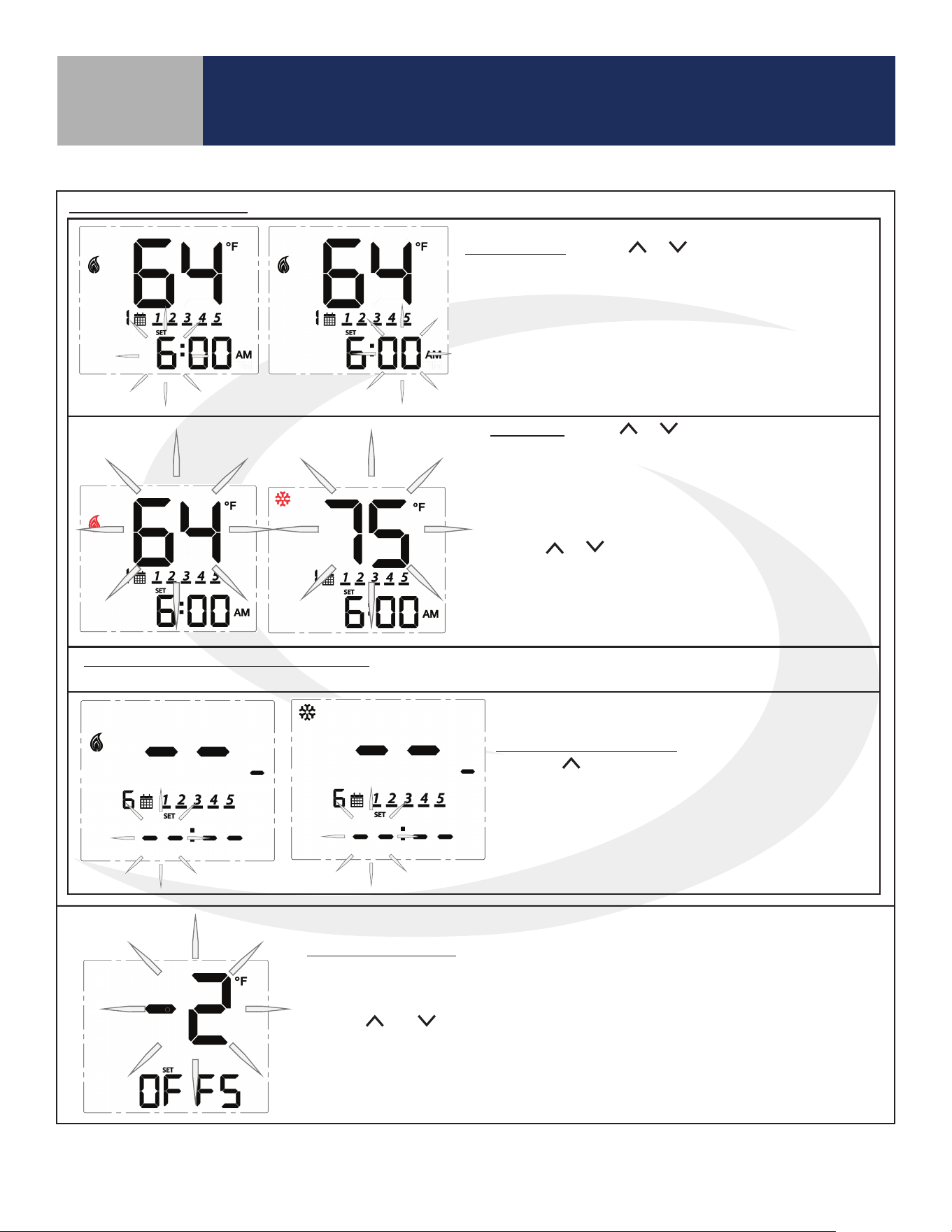
Time Interval: Use the or keys to set the start time
for each time interval, displayed next to the calendar icon.
1st: Set the hour for the time interval start
2nd: Set the minutes for time interval start
Press SELECT to move on to the heating setpoint.
Set Point: Use the or keys to adjust the desired
heating temperature set point for the time interval
displayed.
Press SELECT to accept the set point and move on to
the cooling temperature set point.
Use the or keys to adjust the desired cooling
temperature set point for the time interval displayed.
Press SELECT to accept the set point and move on to
the next interval.
Set points for remaining time intervals: Set the start time and heating and/or cooling temperature for the
remaining interval for a total of 6 intervals.
Skipping a Time Interval: To skip a time interval,
press the key in the hour setting mode until each
of the time and temperature digits change to a “ - “.
When time intervals are completed, the schedule
will return to the first time interval at the scheduled
time.
Schedule (Continued)
Temperature Offset: Change the temperature offset value to adjust the display
of the sensed temperature. This will affect the sensor selected by the INT/EXT
sensor setting.
Use the and keys to set the offset in 1°F (0.5°C) increments. The available
range is -6 to 6°F (-3 to 3°C).
Press SELECT to accept the set point and return to the first item in the
Settings Menu.
Table 8.1: Thermostat Settings (continued)
8-4
Section 8
SC102ZB/ST103ZB Installation and Operation Manual
Thermostat Configuration
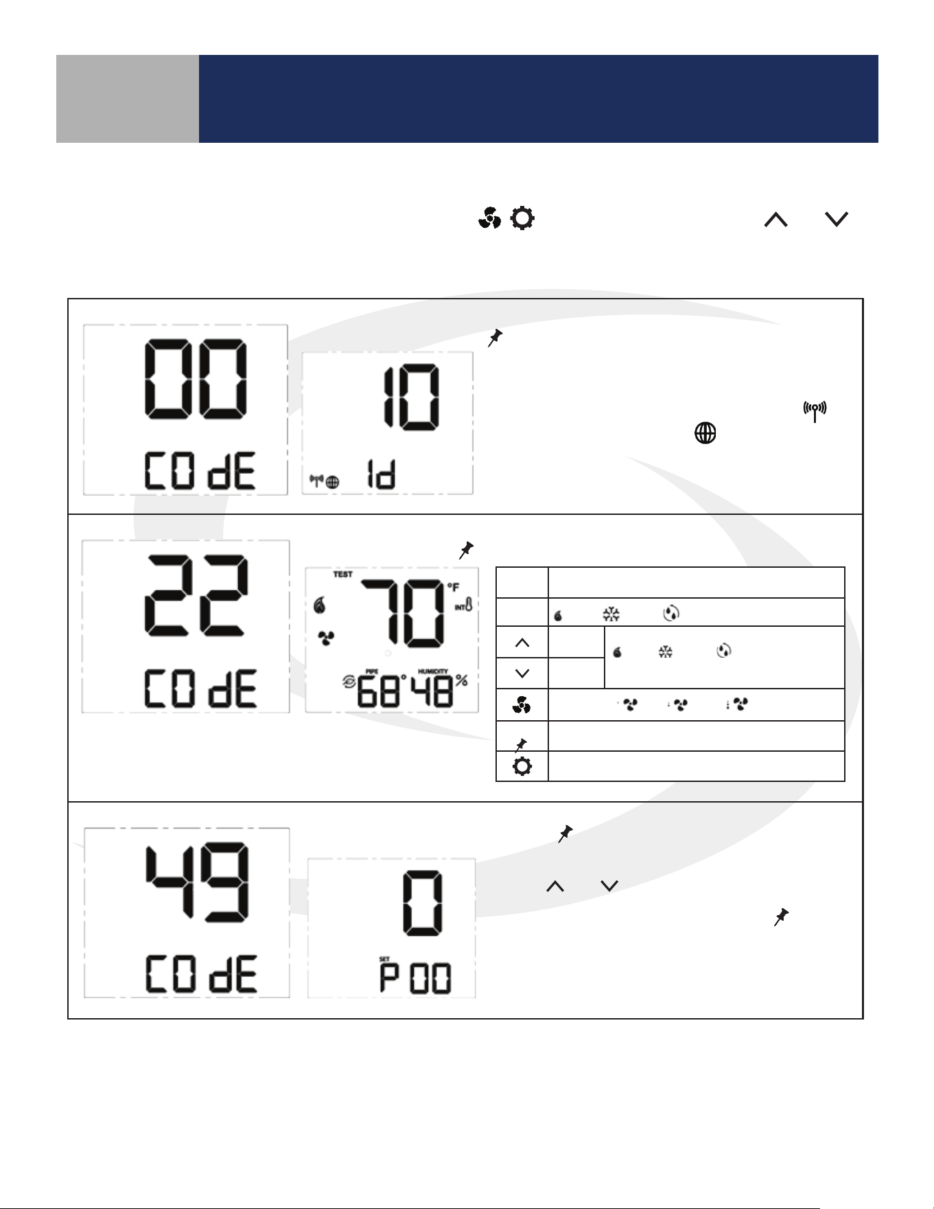
Special Function Codes
To access special functions, press and hold the MODE, , keys simultaneously. Use the and
keys to scroll through the available codes.
Identify Mode – Press
SELECT
to initiate Identify Mode
A 10 minute timer begins with the screen back-
light flashing. If a network is available, the
icon will flash. The internet
will be visible if a
connection is established.
Test Mode – Press
SELECT
to initiate Test Mode
Parameter Setup Mode – Press
SELECT
to initiate Parameter Setup Mode
Use the and keys to change the value of
the parameter that is flashing. Press
SELECT
to
save the current parameter value and advance to
the next parameter. A complete list of parame-
ters is included in Appendix A.
Key Function
MODE
Heat / Cool / Accessory relay select
Turn on
(WY), (YA) or (Ac)
depending on MODE
Turn off
Fan Speed Lo / Med / Hi relay control
SELECT
Toggle HUMIDITY or Zigbee Channel
Exit Test Mode
Table 8.2: Special Function Codes
8-5
Section 8
SC102ZB/ST103ZB Installation and Operation Manual
Thermostat Configuration
Table 8.2: Special Function Codes (continued)
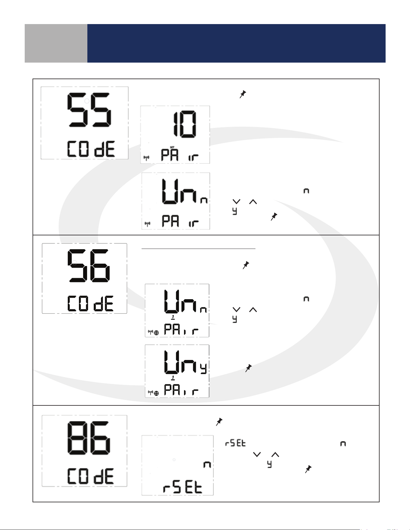
Join/Leave Network – Press
SELECT
to join or leave a network.
Unpair from Remote - Press
SELECT
Press to initiate unpairing with
ST103ZB while remaining on the network.
If the thermostat has not joined a network,
the display will enter the pairing sequence.
Follow the steps under Pairing in Section 3.
If the thermostat is paired with a network,
UnPAir is displayed with “
” flashing. Press
the
or key to change the flashing letter
to “
”. Press
SELECT
to remove the thermo-
stat from the network.
Factory Reset - Press
SELECT
to initiate a factory reset.
SC102ZB Fan Coil Controller Only
UnPAir is displayed with “
” flashing. Press
the
or key to change the flashing letter
to “
”.
Press
SELECT
to disconnect from the
ST103ZB Fan Coil Remote.
is displayed with a flashing “ ”.
Use the
or key to change the flash-
ing letter to “
”. Press
SELECT
to reset the
thermostat to all of the factory default
settings.
9-1
Section 9
SC102ZB/ST103ZB Installation and Operation Manual
Operation
Operating Modes
Fan Coil Thermostats, Controllers and Remotes can be operated in the following operating modes:
• Standalone Mode – when SC102ZB Controller & ST103ZB Remote are paired but not connected to network
• Local Mode – when disconnected from the gateway
• Simple Mode – when connected to the gateway
• Remote: Not Connected – when remote is not on a network and/or not paired with a controller
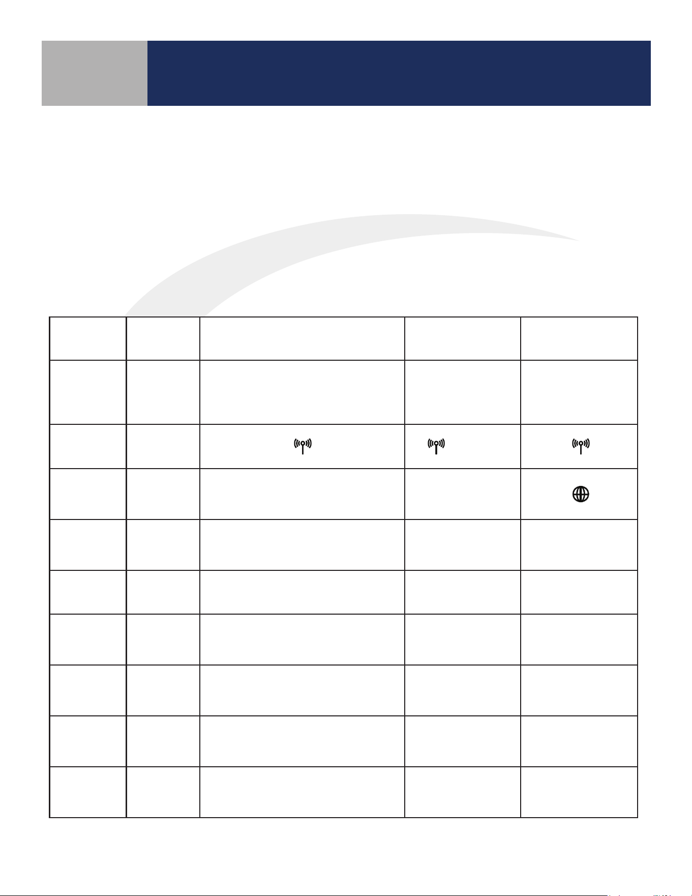
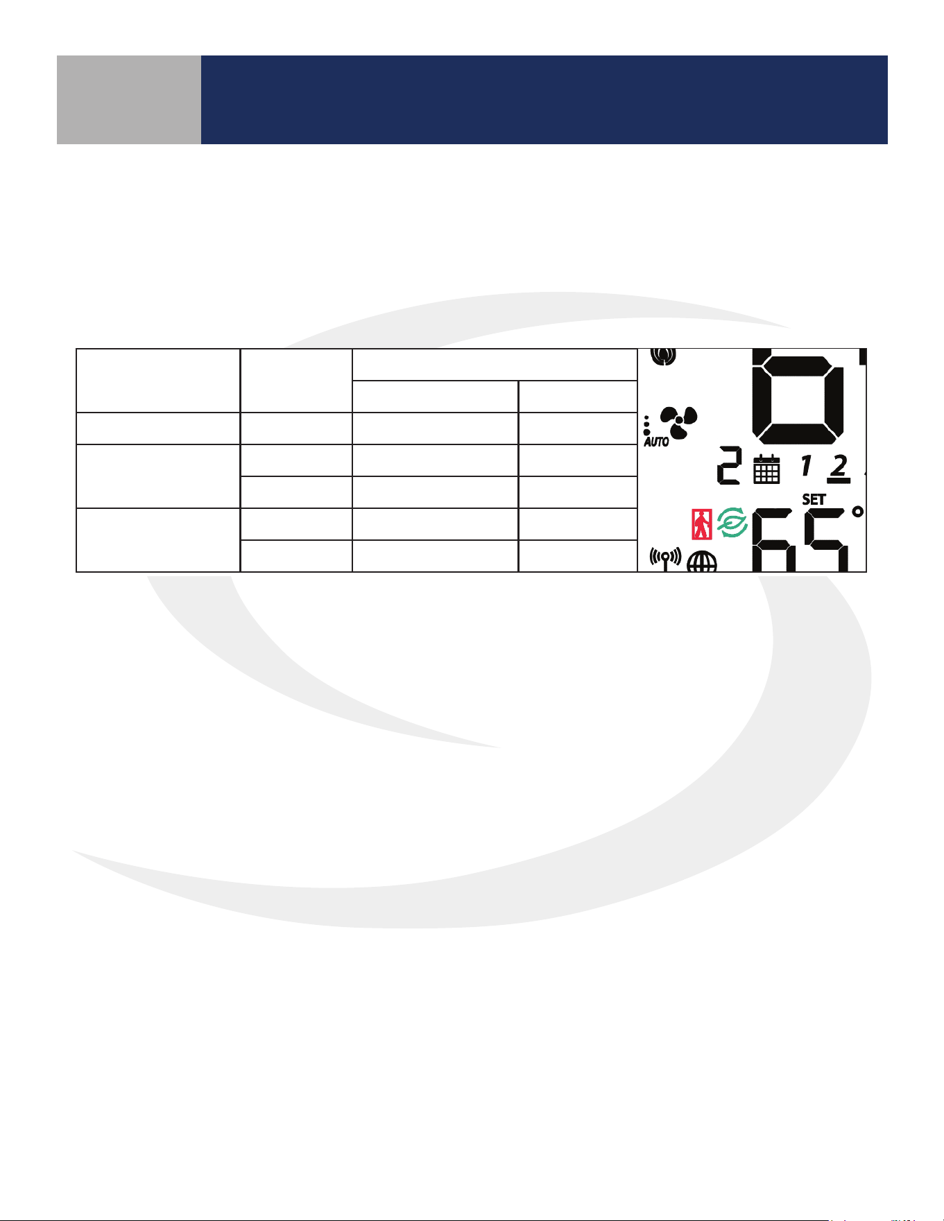
Table 9.1: Operating Modes
Operation
Remote:
Not
Connected
Standalone Mode Local Mode Simple Mode
Network
State
None
SC102ZB acts
as a Zigbee
coordinator
Thermostat is
part of a network,
disconnected from
SG888ZB
Thermostat is
connected to
SG888ZB Universal
Gateway
RF Icon
Display
None
(Flashing)
SALUS
Smart Home
Icon
None None None
SetPoint
Change
Not
Available
Device Only Device Only
Device or SALUS
Smart Home
application
Schedule
Not
Available
In Device, if enabled
In Device,
if enabled
In SALUS Smart
Home application
Change Fan
Speed
Not
Available
Device Only Device Only
Device or SALUS
Smart Home
application
Mode
Change
Not
Available
Device Only Device Only
Device or SALUS
Smart Home
application
Installation
Setup
Not
Available
Device Only Device Only
Device or SALUS
Smart Home
application
Rule based
operation
Not
Available
No No
Through SALUS
Smart Home
application
9-2
Section 9
SC102ZB/ST103ZB Installation and Operation Manual
Operation
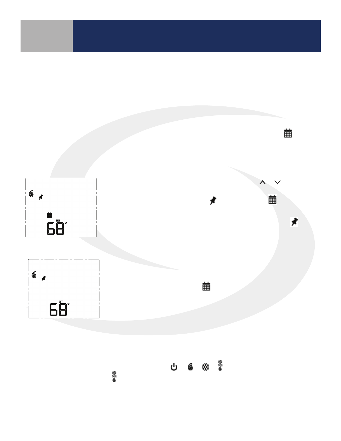
Programmable Thermostat (Standalone or Local Mode Only)
When in Standalone or Local mode, the default operation of the Fan Coil Thermostat is as a Non-
Programmable Thermostat with no scheduling capability. Changing the value of Parameter P00 (See
Appendix A) to 1, changes the device to Programmable, allowing users to program a wide variety of
schedule options. Instructions for setting up a schedule are covered in Section 8: Conguration.
• Temporary Hold
To temporarily override the schedule, simply use the or keys to
change the setpoint. When in Temporary Hold, the LCD display on
the Fan Coil Thermostat will show in addition to the icon. The
schedule will resume when the next scheduled time interval begins.
Change the temperature to the scheduled temperature and the icon
will turn o, indicating that the thermostat is following the schedule.
• Permanent Hold
Once in Temporary Hold, press SELECT to toggle between temporary
and permanent override. When in permanent override, the LCD display
on the Fan Coil Thermostat the icon will turn o. The schedule will
be suspended until the user returns it to the schedule changing the
temperature to the scheduled temperature and pressing SELECT.
Heating/Cooling Modes
Heating/Cooling mode selection works the same for both programmable and non-programmable Fan
Coil Thermostats. Parameter P02 (see appendix) determines which heating and/or cooling modes are
available. Pressing the MODE key, will cycle through
depending on Parameter P02
(Appendix A) settings. When in
mode, the Fan Coil Thermostat will maintain a temperature between
the heating and cooling setpoints.
Set Point Override
While following a temperature schedule in any mode, the Fan Coil Thermostat will display the icon.
The schedule may be overridden temporarily until the next programmed time period, or permanently
until the user returns the device to the programmed schedule.
9-3
Fan Modes
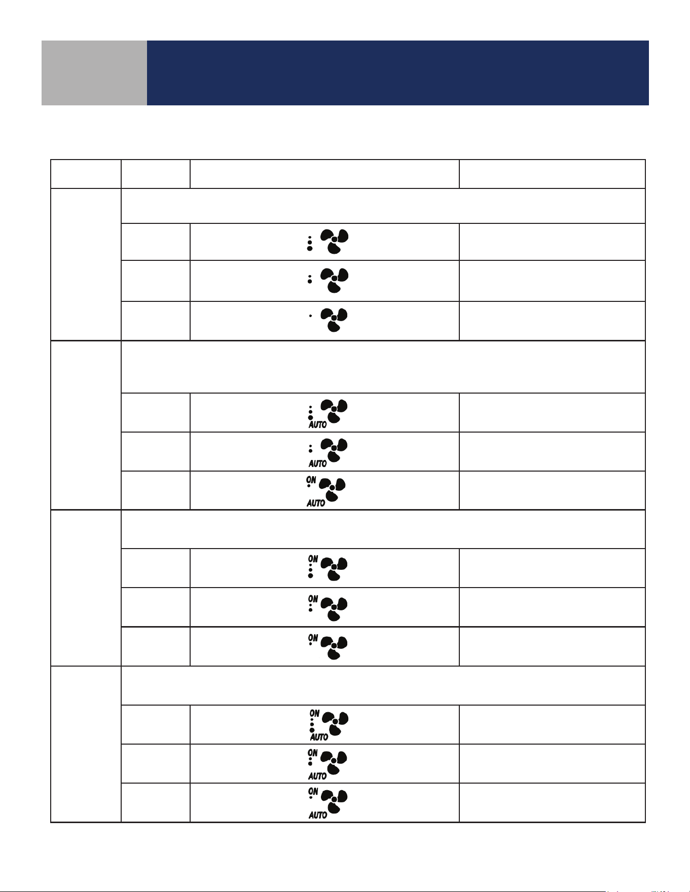
Table 9.2: Fan Modes
Fan Mode Speed Display Output Terminal
Fan output is only activated when a thermostat call is present (On Call Fan).
When a call is present the fan runs at the selected speed.
High
Gh
Medium
Gm
Low
Gl
AUTO
Fan output is only activated when a thermostat call is present (On Call Fan).
When a call is present the fan speed is determined by the TPI/Span algorithm selected in
Parameter 23 (See Appendix A).
High
Gh
Medium
Gm
Low
Gl
ON *
Fan output is constant at the selected speed.
The fan will remain running when a thermostat call is not present.
High
Gh
Medium
Gm
Low
Gl
ON-AUTO *
Fan output is only activated when a thermostat call is present (On Call Fan). When a call is present, the
fan speed is determined by the TPI/Span algorithm selected in Parameter 23 (See Appendix A).
High Gh
Medium Gm
Low Gl
* When in constant fan output, the fan coil will automatically switch to On Call Fan 2 or 4 hours
after the initial call for heat or cool is satised (P35).
Section 9
SC102ZB/ST103ZB Installation and Operation Manual
Operation
9-4
P22 - Accessory Function
Terminals Ac1 and Ac2 on the Fan Coil Thermostat provide output to an accessory such as a Humidier,
Dehumidier, Heat Recovery Ventilator (HRV) or Energy Recovery Ventilator (ERV).The built-in humidity
monitor continually samples humidity at the thermostat and will operate a humidier or dehumidier to
maintain the specied value. The Table 9.3 shows the function of the accessory output depending on which
accessory is selected under parameter 22 (See Appendix A).
Table 9.3: Parameter 22 - Accessory Function
Parameter P22 Setting Operation of Ac1/Ac2 dry contacts
0 (No Function) Open
1 (Humidifier)
Closed when humidity is at
or below the set point
Open when the humidity
exceeds the set point
2 (Dehumidifier)
Closed when humidity is at
or above the set point
Open when the humidity is
less than the set point
3 (ERV/HRV) Closed when fan relay is on Open when fan relay is off
The icon is displayed when the Ac1/Ac2 dry contacts are closed.
Section 9
SC102ZB/ST103ZB Installation and Operation Manual
Operation
9-5
P16 - AWAY Mode
Fan Coil Thermostat terminals Ts and Tc are used to initiate or terminate an Away state in the device. The
Ts/Tc contact closure is congured by P16 as a Normally Open or Normally Closed contact, or as an input
to be ignored.
Table 9.4: AWAY Mode Function
P16
Ts/Tc
Status
P21
0 (Setback Mode) 1(Off Mode)
0 (Disabled) Ignored Inactive Inactive
1 (Normally Closed)
Open Setback Off
Close Inactive Inactive
2 (Normally Open)
Open Inactive Inactive
Close Setback Off
A contact state change detected between the two terminals will initiate the Away timers (P19 or P20)
and once the timers expire, the device will enter or exit AWAY mode (indicated by the “person in doorway”
icon). The timers are canceled if the contact input changes while the timers are active.
If Setback is selected when in AWAY mode (P21), the Setback set points (P17 and P18) will be in eect
(indicated by “leaf” icon), overriding any schedules.
Section 9
SC102ZB/ST103ZB Installation and Operation Manual
Operation
10-1
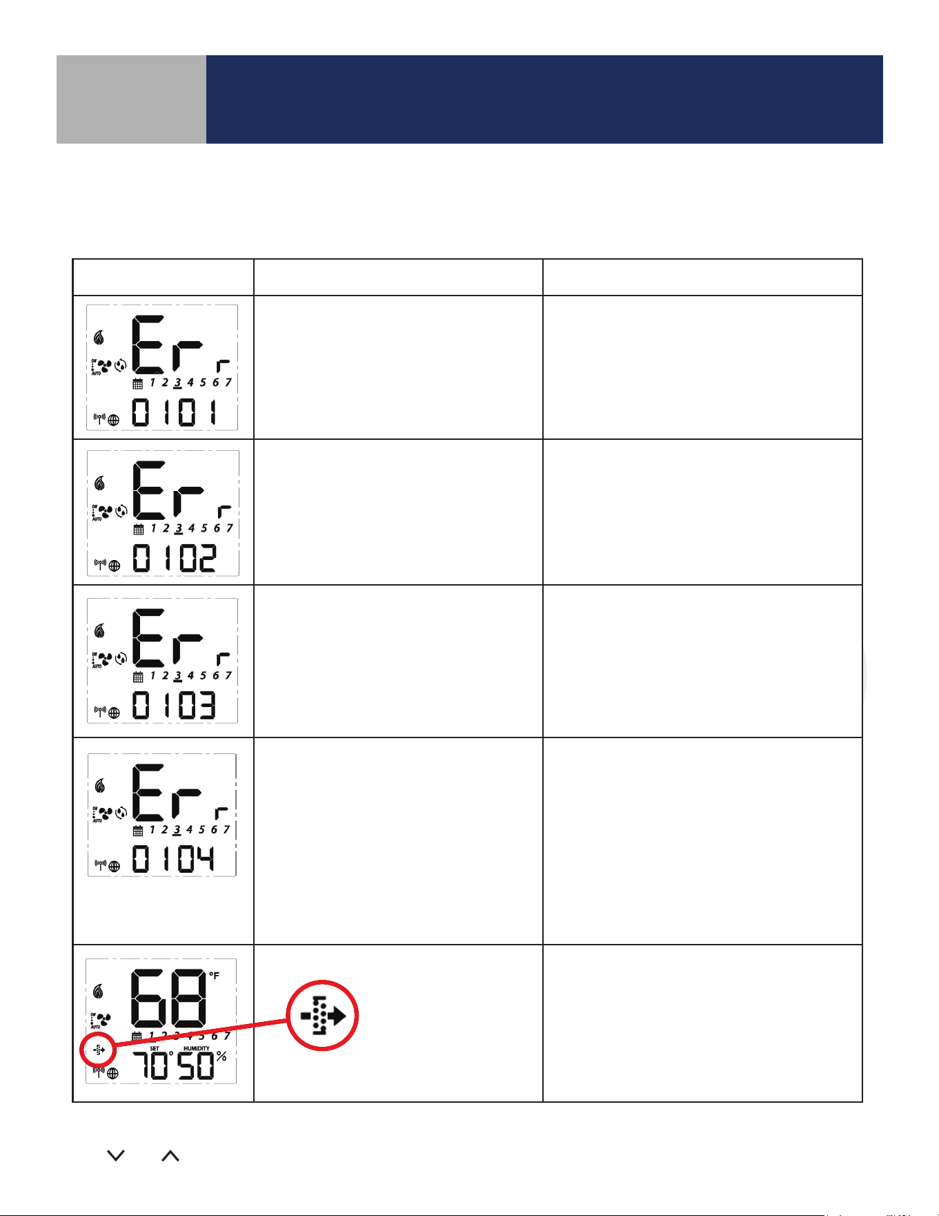
Error Message Description Corrective Action
Error 01: Pipe supply sensor circuit is
open, or pipe supply sensor is not
connected. The pipe supply sensor must
be used if Parameter P02 = 3 or 4 (See
Parameters Appendix A).
• Check connection of pipe supply sensor
to terminals
• Replace sensor
Error 02: Pipe supply sensor circuit is
shorted, or pipe supply sensor damaged.
The pipe supply sensor must be used if
Parameter P02 = 3 or 4 (See Parameters
Appendix A).
• Check connection of pipe supply sensor
to terminals
• Check for shorts in pipe supply sensor leads
• Replace sensor
Error 03: Room temperature sensor
circuit is shorted, or room temperature
sensor damaged.
• If sensor is set to External (Settings), and
Parameter 12 (Appendix A) is set to external
sensor, check for short circuit
• If sensor is set to Internal (default), replace
thermostat or use external sensor
Error 04: Room temperature sensor
circuit is open.
• If sensor is set to Internal (Default), replace
thermostat or use external sensor
• If sensor is set to External (Settings), and
Parameter 12 (Appendix A) is set to external
sensor, check wiring or assure sensor is
connected.
• If sensor is set to External and Parameter 12
is set to Zigbee remote, go through the
“Find & Bind” sequence defined in the IOM.
Error 05: Filter is clogged • Change filter
The following error messages are displayed to identify issues when certain conditions occur.
Table 10.1: Error Messages
For Errors 01-04 the display will alternate between the message above and the Home Screen. The total
number of errors (shown 01 above) will be the rst two digits displayed. If more than 1 error exists, press
the
and keys to review each error.
Troubleshooting
Section 10
SC102ZB/ST103ZB Installation and Operation Manual
Troubleshooting

11-1
Section 11
SC102ZB/ST103ZB Installation and Operation Manual
Installer Notes
Installer Notes
A-1
Appendix A
P Name Values Default Description/Comment
P00 Type of thermostat
0 = Non-Programmable
1 = Programmable
0
P01 Fan Coil Type
0 = 2 Pipe
1 = 4 pipe
1
P02 Heat/Cool Option
For 2 Pipe
3
Option #3 & #4 in the 2 pipe
configuration require the pipe
sensor (sold separately) to be
connected
0=Heat Only
1=Cool Only
2 = Heat or Cool Manual changeover
3 = Heat or Cool Seasonal changeover
4 = Heat or Cool with Auxiliary Heat
For 4 Pipe:
2 = Heat or Cool Manual changeover
3 = Heat, Cool or Auto changeover
4 = Auto changeover only
P03 Valve Type
0 = Normally Closed Valve
1 = Normally Open Valve
0
P04 Max. heating setpoint 41 to 92°F (5 to 33.5°C)
92°F
(33.5°C)
Not displayed if P02 = 1
P05 < P04
P04 ≤ P06-1.5°C
P05 Min. heating setpoint 41 to 92°F (5 to 33.5°C)
41°F
(5°C)
Not displayed if P02 = 1
P05 < P04
P05 ≤ P07-1.5°C
P06 Max. cooling setpoint 44 to 95°F (6.5 to 35°C)
95°F
(35°C)
Not displayed if P02 = 0
P07 < P06
P06 ≥ P04+1.5°C
P07 Min. cooling setpoint 44 to 95°F (6.5 to 35°C)
44°F
(6.5°C)
Not displayed if P02=0
P07 < P06
P07 ≥ P05+1.5°C
P08
Protection heating
setpoint
OFF or 41 to 92°F
(OFF or 5 to 33.5°C)
41°F
(5°C)
If not OFF, P05 < P08 < P04
P08 < P09
P09
Protection cooling
setpoint
OFF or 44 to 95°F
(OFF or 6.5 to 35°C)
OFF
If not OFF, P07 < P09 < P06
P08 < P09
P10
Offset of internal
sensor
±6°F - 1°F increments
(±3°C - 0.5°C increments)
0°F
(0°C)
P11
Offset of external
sensor
±6°F - 1°F increments
(±3°C - 0.5°C increments
0°F
(0°C)
P12 External sensor
0 = External sensor
1 = Zigbee remote sensor
0
Standalone mode: P12 = 0
Set
to EXT with key
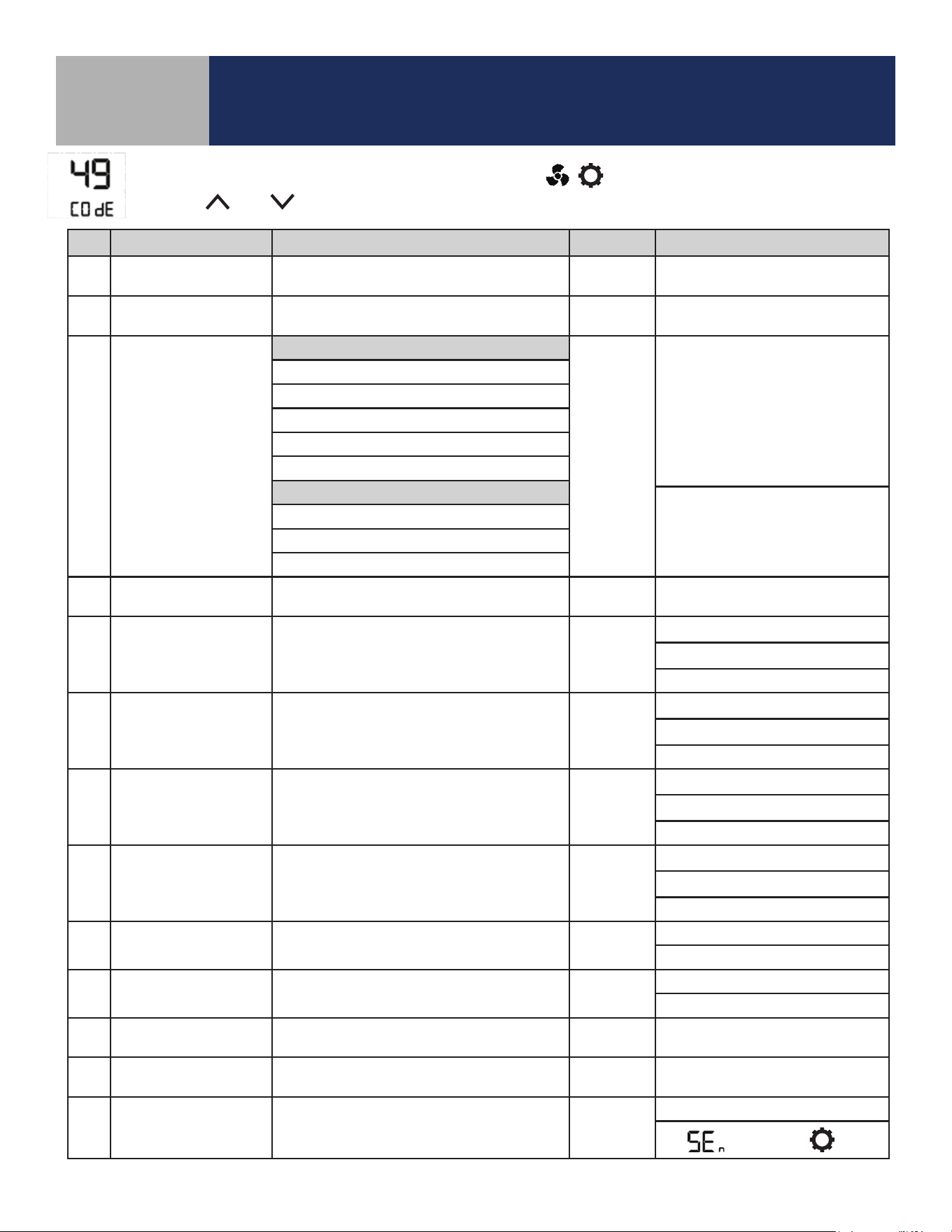
To change parameters, press and hold the MODE, , keys simultaneously.
Use the
and keys to scroll to “49” and press SELECT.
SC102ZB/ST103ZB Installation and Operation Manual
Parameter List
A-2
P Name Values Default Description/Comment
P13 Pipe sensor
0 = Analog input
0
Displayed only if P01=0 and
P02=3 or 4
NOTE: PO2 option #3 & #4 in the
2-pipe configuration require the
pipe sensor (sold separately) to
be connected.
1 = Normally open, default mode is Heat
2 = Normally open, default mode is Cool
3 = Normally closed, default mode is Heat
4 = Normally closed, default mode is Cool
P14
Pipe sensor threshold
for cooling
50 to 77°F increment 1°F
(10 to 25°C increment 0.5°C)
50°F
(10°C)
P15
Pipe sensor threshold
for heating
81 to 95°F increment 1°F
(27 to 35°C increment 0.5°C)
86°F
(30°C)
P16 Setback input
0 = Disable
0
1 = Normally closed
2 = Normally open
P17
Setback heating
setpoint
50 to 68°F increment 1°F (10 to 20°C
increment 0.5°C)
15°C
(59°F)
Display only if P16=1/2
P18
Setback cooling
setpoint
23 to 32°C increment 0.5°C
(73 to 90°F increment 1°F)
86°F
(30°C)
Display only if P16=1/2
P19
Setback Unoccupied
to Occupied delay
1 to 3 seconds 1 sec Display only if P16=1/2
P20
Setback Unoccupied
to Occupied delay
2 to 30 minutes 2 mins Display only if P16=1/2
P21
Setback mode or Off
mode when unoccu-
pied
0 = Setback mode
1 Display only if P16=1/2
1 = Off mode
P22 Accessory function
0 = No function
0 Normally Open
1 = Humidifier
2 = Dehumidifier
3 = ERV/HRV
P23 TPI or Span
0 = TPI
1
1 = Span control
P24
Modulation Response
Time
0 = Slow response time
1 Display only if P23=0
1= Fast response time
P25 TPI heat control CPH 3 ~ 12 on/off cycle per hour 6 Display only if P23=0
P26 TPI cool control CPH 3 ~ 12 on/off cycle per hour 3 Display only if P23=0
P27
CPH for Auxiliary
Electrical Heater
3 ~ 12 on/off cycle per hour 6 Display only if P23=0
P28
Set span for heating
using span control
.5° to 2°F increment 0.5°F
(0.25° to 1°C increment 0.25°)
0.5°F
(0.25°C)
Display only if P23=1, device
only display 0.2/0.5/0.7/1.0°C or
0.5/1.0/1.5/2.0°F
P29
Set span for cooling
using span control
0.5° to 2°F increment 0.5°F
(0.25° to 1°C increment 0.25°)
0.5°F
(0.25°C)
Display only if P23=1, device
only display 0.2/0.5/0.7/1.0°C or
0.5/1.0/1.5/2.0°F
Appendix A
SC102ZB/ST103ZB Installation and Operation Manual
Parameter List
A-3
P Name Values Default Description/Comment
P30
Set the minimum
turn off time for
heating mode
respectively
10 to 300 seconds 10 Display if P02<>1
P31
Set the minimum
turn off time for
cooling mode
respectively
10 to 300 seconds 10 Display if P02<>0
P32 Call start delay From 0 to 15 minutes 0
Delay after determining Call for
Heat/Cool before valve is opened.
P33 Fan turn on delay 0 to 600 seconds 0
Delay to allow coils to reach oper-
ating temp
P34 Fan turn off delay 0 to 180 seconds 0
Delay to circulate residual heat/
cool.
P35
Resume Auto fan
delay after initial
Heat/Cool is satisfied.
0=2 hours
0
1=4 hours
P36
*
Key lock timing
0 = Manual
0
Note: In Auto mode, keys will
lock after 5 minutes of keypad
inactivity.
1 = Auto (lock keys after 5 minutes)
2 = Unlock
P37
*
Enable/Disable User
Unlock in Simple
mode and Local
mode
0 = user can unlock by
and 0
In Standalone Mode, user can un-
lock by
and regardless P37
setting
1 = user cannot unlock by
and
P38 Service filter
OFF
OFF
1 to 99 x 100 operating hrs (e.g. 99
= 9,900 oper. hrs)
1 to 99 (99 means 9900hrs = 99*100)
P39
Status after power
outage
0 = Off mode
1
Thermostat will turn Off or be
restored to Last configuration.
1 = Last configuration
P40
DST
Daylight saving time
0: Disable
1
Used for local mode and stand-
alone mode
1: Enable
P41 Purge Function
0: Disable
1
1: Enable
P42 Purge Time 1-7 3 Minutes to purge
P43 Purge Wait 6-36 24 Hours of inactivity before purge
P44
*
Key lock type
1: Lock HVAC only
7
HVAC = Mode and set point
Fan = fan button
Settings = Settings button
Combination key pressing will not
be locked at any time.
2: Lock Fan only
3: Lock HVAC and Fan
4: Lock Settings
5: Lock Settings and HVAC
6: Lock Settings and Fan
7: Lock All
* SC102ZB Controller and each ST103ZB Remote is controlled locally and can be set to dierent P36/P37/P44 values.
Appendix A
SC102ZB/ST103ZB Installation and Operation Manual
Parameter List