
PROGRAMMABLE CONTROLLER
Version 4.0 Page 1 113635e
PROGRAMMABLE CONTROLLER
TABLE OF CONTENTS PAGE
Key Functions 2
Display 3
Starting Up and Operating Controller 3
System Status 3
Set Up Menu 4
Setpoints 5
Temperature Setpoint 5
Humidity Setpoint 5
Lighting Setpoint 6
CO2 Setpoint 6
Air Temperature Alarm 6
Product Alarm 7
Humidity Alarm 7
CO2 Alarm 8
Defrost Set Up 8
Ramp and Soak 9
Parameters 11
Real Time Clock 11
CO2/Humidity/Lighting Enable 11
Door Ajar Alarm 12
Audible Alarm 12
Temp. Valve Set-up 13
Heat Offset 13
Humidifier Offset 14
Dehumidifier Offset 14
CO2 Offset 15
Passwords 15
Communications 16
Calibration 16
Quality Control 18
Actual Temperature 18
Alarm Test 18
Alarms 20
Technical Specifications 24
PROGRAMMABLE CONTROLLER
Version 4.0 Page 2 113635e
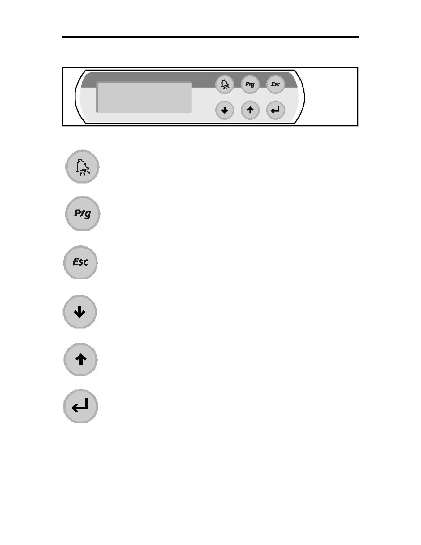
FRONT PANEL VIEW
KEY FUNCTIONS
ALARM KEY: Displays active alarms, alarm history, acknowledge alarms,
and clear alarms. Back lit when an alarm is active.
PROGRAM KEY: Allows access to set points and main control parameters.
ESCAPE KEY: Returns to the main menu.
DOWN KEY: Decreases parameter values, and scrolls through
screens.
UP KEY: Increases parameter values, and scrolls through
screens.
ENTER KEY: Moves the cursor between parameter fields and
confirms the set data.

PROGRAMMABLE CONTROLLER
Version 4.0 Page 3 113635e
DISPLAY
liquid crystal display (LCD)
LCD Display
Features
number of lines: 4
number of characters per line: 20
character height: 5 mm
STARTING UP AND OPERATING THE CONTROLLER
KEY: ESCAPE
Pressing the ESC key will display the following screen. The SYSTEM STATUS screens are display only.
To change set points the values must be entered at the corresponding screens. To view the other SYSTEM
STATUS screen press the UP or Down Arrow keys.
Note: The main system status screen will change in appearance depending on what options are
enabled in the control. The following three screens show what the main system status screen will
look like with different options.
This screen displays the product temperature and current date and time.
SYSTEM STATUS
Product Temp: 04.0°
°°
°C
12:00:00 05/18/02
SYSTEM STATUS
P1:04.0°C P2:04.0°C
12:00:00 05/18/02

PROGRAMMABLE CONTROLLER
Version 4.0 Page 4 113635e
This screen is displayed when the second product sensor is active.
This screen displays the product temperature and current date and time.
This screen is the will be seen when the second product temperature sensor is used. The screen shows the
two product temperatures (P1, P2) of the cabinet, humidity level (when enabled), percentage of lighting
(when enabled), CO2 level and the current date and time.
This screen displays the refrigeration current set points.
KEY: PROGRAM
Pressing the PRG key will display the following screen.
This screen allows access to the listed set up screens. Press the ENT key to move the cursor to the desired
field and press the Up or Down Arrow key to scroll through the screens of each group.
SET POINTS
Note: If the password protection is used the following screen will be displayed before allowing access
to the SET POINTS screens. On initial start up there is no password protection the passwords
are set in the PARAMETERS group. If no password protection is used the “ENTER
PASSWORD” screen will not be displayed.
CURRENT SET POINTS
TEMPERATURE: 04.0
°
°°
°C
HUMIDITY: 50.0%RH
LTS:100% CO2:100%
SET UP MENU
SET POINTS >
PARAMETERS >
SENSOR TEST >
ENTER PASSWORD
0000
WRONG PASSWORD
SYSTEM STATUS
P1:04.0°C P2:04.0°C
50.0% RH CO2: 6.6 %
12:00:00 05/18/02

PROGRAMMABLE CONTROLLER
Version 4.0 Page 5 113635e
Press the ENT key to move the cursor to the four-digit password. Use the Up or Down Arrow key to
increase or decrease the number. When the correct password is displayed press the ENT key to enter the
password. If the correct password was entered the corresponding screen will be displayed. If a wrong
password was entered “WRONG PASSWORD” will be displayed on the bottom line. The password can
be re-entered or press the ESC key to return to the System Status screen.
SET POINTS: Screen 1
Factory Default Setting: 4.0°
°°
°C
Note: If the schedule is enabled the temperature will be set through the ramp and soak schedule. To
disable the ramp and soak schedule press the ENT key to move the cursor to the schedule field. Use
the Up or Down Arrow key to disable the schedule. Press the ENT key and the cursor will move to
the upper left hand corner and the set point will be visible. A full explanation of the ramp and soak
schedule follows.
Press the ENT key to move the cursor to the set point data field. Use the Up or Down Arrow key to
increase or decrease the number. When the correct set point is displayed press the ENT key to enter the set
point, the cursor will move to the schedule field. Press the ENT key and the cursor will move to the upper
left hand corner. Press the Up or Down Arrow key to scroll through the other screens or press the ESC key
to return to the System Status screen.
SET POINTS: Screen 2
Note: The following screen will only be visible if the humidity is enabled in the Parameter section.
Factory Default Setting: 50.0%
Press the ENT key to move the cursor to the set point data field. Use the Up or Down Arrow key to
increase or decrease the number. When the correct set point is displayed press the ENT key to enter the set
point, the cursor will move to the upper left hand corner. Press the Up or Down Arrow key to scroll
through the other screens or press the ESC key to return to the System Status screen.
TEMPERATURE
SET POINT
04.0°
°°
°C
SCHEDULE >DISABLED
HUMIDITY
SET POINT
050.0% R.H.

PROGRAMMABLE CONTROLLER
Version 4.0 Page 6 113635e
SET POINTS: Screen 3
Note: The following screen will only be visible if the Lights are enabled in the Parameter section.
Factory Default Setting: 100%
Press the ENT key to move the cursor to the set point data field. Use the Up or Down Arrow key to
increase or decrease the number. When the correct set point is displayed press the ENT key to enter the set
point, the cursor will move to the upper left hand corner. Press the Up or Down Arrow key to scroll
through the other screens or press the ESC key to return to the System Status screen.
SET POINTS: Screen 4
Note: The following screen will only be visible if the CO2 option is enabled in the Parameter section.
Factory Default Setting: 6.0%
Press the ENT key to move the cursor to the set point data field. Use the Up or Down Arrow key to
increase or decrease the number. When the correct set point is displayed press the ENT key to enter the set
point, the cursor will move to the upper left hand corner. Press the Up or Down Arrow key to scroll
through the other screens or press the ESC key to return to the System Status screen.
SET POINTS: Screen 5
Factory Default Setting: High Alarm 70.0°
°°
°C
Factory Default Setting: Low Alarm 0.0°
°°
°C
Factory Default Setting: Alarm Delay 120 Sec
Press the ENT key to move the cursor to the set point data field. Use the Up or Down Arrow key to
increase or decrease the number. When the correct value is displayed press the ENT key to enter the set
point, the cursor will move to the next data field. Press enter to move the cursor to the upper left hand
AIR TEMP. ALARM
HIGH ALARM > 70.0°
°°
°C
LOW ALARM > 00.0°
°°
°C
ALARM DELAY> 120 SEC
LIGHTING
SET POINT
100%
CO2
SET POINT
6.0%

PROGRAMMABLE CONTROLLER
Version 4.0 Page 7 113635e
corner and the Up or Down Arrow key to scroll to the next set point screen or press the ESC key to return
to the System Status screen.
Note: The High and Low Air Temperature Alarms provide an early warning prior to the product
temperature alarm. They should be set to allow the normal rise and fall of the air temperature
during normal operation. High ambient temperature and heavy door use may require a
longer Alarm Delay. The ALARM DELAY is the amount of time in seconds that the
temperature must be above or below the alarm set point for the alarm to activate.
SET POINTS: Screen 6
Factory Default Setting: High Alarm 70.0°
°°
°C
Factory Default Setting: Low Alarm 0.0°
°°
°C
Factory Default Setting: Alarm Delay 120 Sec
Press the ENT key to move the cursor to the set point data field. Use the Up or Down Arrow key to
increase or decrease the number. When the correct value is displayed press the ENT key to enter the set
point, the cursor will move to the next data field. Press enter to move the cursor to the upper left hand
corner and the Up or Down Arrow key to scroll to the next set point screen or press the ESC key to return
to the System Status screen.
Note: This setting will be applicable to cabinets equipped with a single Product temperature sensor
or two sensors. The ALARM DELAY is the amount of time in seconds that the temperature
must be above or below the alarm set point for the alarm to activate.
SET POINTS: Screen 7
Note: The following screen will only be visible if the Humidity is enabled in the Parameter section.
Factory Default Setting: High Alarm 100.0%
Factory Default Setting: Low Alarm 0.0°
°°
°%
Factory Default Setting: Alarm Delay 120 Sec
Press the ENT key to move the cursor to the set point data field. Use the Up or Down Arrow key to
increase or decrease the number. When the correct value is displayed press the ENT key to enter the set
point, the cursor will move to the next data field. Press enter to move the cursor to the upper left hand
corner and the Up or Down Arrow key to scroll to the next set point screen or press the ESC key to return
to the System Status screen.
PRODUCT TEMP. ALARM
HIGH ALARM > 70.0°
°°
°C
LOW ALARM > 00.0°
°°
°C
ALARM DELAY> 120 SEC
HUMIDITY ALARMS
HIGH ALARM > 100.0%
LOW ALARM > 000.0%
ALARM DELAY> 120 SEC

PROGRAMMABLE CONTROLLER
Version 4.0 Page 8 113635e
Note: The ALARM DELAY is the amount of time in seconds that the humidity level must be above
or below the alarm set point for the alarm to activate.
SET POINTS: Screen 8
Note: The following screen will only be visible if the CO2 is enabled in the Parameter section.
Factory Default Setting: High Alarm 55.0%
Factory Default Setting: Low Alarm 0.0°
°°
°%
Factory Default Setting: Alarm Delay 120 Sec
Press the ENT key to move the cursor to the set point data field. Use the Up or Down Arrow key to
increase or decrease the number. When the correct value is displayed press the ENT key to enter the set
point, the cursor will move to the next data field. Press enter to move the cursor to the upper left hand
corner and the Up or Down Arrow key to scroll to the next set point screen or press the ESC key to return
to the System Status screen.
Note: The ALARM DELAY is the amount of time in seconds that the CO2 level must be above or
below the alarm set point for the alarm to activate.
SET POINTS: Screen 9
Factory Default Setting: Dehumidifier Defrost > Disabled
Factory Default Setting: DF Interval: 60 min.
Factory Default Setting: DF Length: 30 sec.
Press the ENT key to move the cursor to the set point data field. Use the Up or Down Arrow key to
increase or decrease the number. When the correct value is displayed press the ENT key to enter the set
point, the cursor will move to the next data field. Press enter to move the cursor to the upper left hand
corner and the Up or Down Arrow key to scroll to the next set point screen or press the ESC key to return
to the System Status screen.
DEFROST: Enables or disables the defrost cycle of the dehumidification evaporator coil..
DF Interval: The amount of time in minutes that the dehumidification coil has to be active to initiate
an off cycle defrost.
DF Length: The length in seconds of the defrost cycle.
Dehumidi
fier Defrost
Disabled
DF Interval: 60 min.
DF Length: 30 sec.
CO2 ALARMS
HIGH ALARM > 055.0%
LOW ALARM > 000.0%
ALARM DELAY> 120 SEC
PROGRAMMABLE CONTROLLER
Version 4.0 Page 9 113635e
RAMP AND SOAK SCHEDULE
SET POINTS: Screen 1
Press the ENT key until the cursor moves to the schedule field. Use the Up or Down arrow key to enable
the schedule. Press the ENT key and the first of 21 Ramp and Soak screens will be displayed.
RAMP & SOAK
Weekly/Daily:
Daily, Mon, Tues, Wed,
Thur, Fri, Sat, Sun.
Time
Temperature Set Point
Humidity Set Point
Lighting Set Point
Ramp/Hold:
Ramp Set Point or Hold Set Point
Press the ENT key and the cursor moves to the Day of the Week/Daily field. Use the Up or Down arrow
key to select daily or the day of the week the schedule is to begin. Press the ENT key and the cursor will
move to the time field. Use the Up or Down arrow key to enter the desired time to change the set points.
Press the ENT key and the cursor will move to the temperature set point field. Use the Up or Down arrow
key to enter the desired temperature set point. Press the ENT key and the cursor will move to the humidity
set point field (if activated). Use the Up or Down arrow key to enter the desired humidity set point. Press
the ENT key and the cursor will move to the light set point field (if activated). Use the Up or Down arrow
key to enter the desired lighting set point.
Press the ENT key and the cursor will move to the Ramp / Hold field. Use the Up or Down arrow key to
select to Ramp the set point to the next scheduled set point or to Hold the set point until the next scheduled
set point. Press the ENT key and the cursor will move to the upper left hand corner. Press the Down arrow
key to go to the next schedule.
Note: If Daily is selected on the Program #1 screen programs 1 through 21 will repeat each day. Any
unused programs will have to be turned off.
TEMPERATURE
SET POINT
04.0°
°°
°C
SCHEDULE >DISABLED
Program #1 Mon
12:01 04.0°C
50.0%RH Lights:100%
Ramp Set Point

PROGRAMMABLE CONTROLLER
Version 4.0 Page 10 113635e
Ramp and Soak Example
The following example will ramp from 4.0°C to 10.0°C every Monday from 06:00 to 12:00. The
temperature will remain at 10.0°C until Wednesday at 06:00 when it will begin ramping the set point down
to 4.0°C at 12:00 Wednesday. The set point will remain at 4.0°C until Friday at 06:00 when it will begin
ramping the set point up to 10.0°C at 12:00 Friday. The set point will remain at 10.0°C until Sunday at
06:00 when it will begin ramping the set point down to 4.0°C at 12:00 Sunday. The temperature set point
will remain at 4.0°C until the schedule repeats Monday at 06:00.
It is recommended to fill out the Ramp and Soak worksheet on page 26 of this manual before programming
the ramp and soak functions of the controller.
Program #
Daily/Weekly Time Temp.
Humidity Lights Ramp/Hold
1 Mon. 6:00 4.0°C
N/A N/A Ramp
2 Mon. 12:00
10.0°C
N/A N/A Hold
3 Wed. 6:00 10.0°C
N/A N/A Ramp
4 Wed. 12:00
4.0°C
N/A N/A Hold
5 Fri. 06:00
4.0°C
N/A N/A Ramp
6 Fri. 12:00
10.0°C
N/A N/A Hold
7 Sun. 06:00
10.0°C
N/A N/A Ramp
8 Sun. 12:00
4.0°C
N/A N/A Hold
9 Off N/A N/A
10 Off N/A N/A
11 Off N/A N/A
12 Off N/A N/A
13 Off N/A N/A
14 Off N/A N/A
15 Off N/A N/A
16 Off N/A N/A
17 Off N/A N/A
18 Off N/A N/A
19 Off N/A N/A
20 Off N/A N/A
21 Off N/A N/A

PROGRAMMABLE CONTROLLER
Version 4.0 Page 11 113635e
PARAMETERS
Note: If the passwords are used the following screen will be displayed. On initial start up there is no
password protection the passwords are set in the PARAMETERS group. If no password
protection is used the “ENTER PASSWORD” screen will not be displayed.
Press the ENT key to move the cursor to the four-digit password. Use the Up or Down Arrow key to
increase or decrease the number. When the correct password is displayed press the ENT key to enter the
password. If the correct password was entered the corresponding screen will be displayed. If a wrong
password was entered “WRONG PASSWORD” will be displayed on the bottom line. The password can
be re-entered or press the ESC key to return to the System Status screen.
PARAMETERS: Screen 1
Press the ENT key to move the cursor to the set point data field. Use the Up or Down Arrow key to
increase or decrease the number. When the correct value is displayed press the ENT key to enter the
parameter, the cursor will move to the next data field. Press enter to move the cursor to the upper left hand
corner and the Up or Down Arrow key to scroll to the next set parameter screen or press the ESC key to
return to the System Status screen.
PARAMETERS: Screen 2
Factory Default Setting: CO2 > Disabled
Factory Default Setting: HUMID > Disabled
Factory Default Setting: DEHUMID > Disabled
Factory Default Setting: LIGHTING > Disabled
Press the ENT key to move the cursor to the set point data field. Use the Up or Down Arrow key to toggle
between enabled and disable. When the correct setting is displayed press the ENT key to enter the
parameter, the cursor will move to the next data field. Press enter to move the cursor to the upper left hand
corner and the Up or Down Arrow key to scroll to the next set parameter screen or press the ESC key to
return to the System Status screen.
ENTER PASSWORD
0000
WRONG PASSWORD
REAL TIME CLOCK
CURRENT TIME/DATE
SET TIME: 00:00
SET DATE: 00/00/00
CO2
> ENABLED
HUMID> ENABLED
DEHUMID> ENABLED
LIGHTING> ENABLED

PROGRAMMABLE CONTROLLER
Version 4.0 Page 12 113635e
PARAMETERS: Screen 3
Factory Default Setting: Door Ajar Al. > Disabled
Factory Default Setting: Delay > 5 min.
Press the ENT key to move the cursor to the set point enable/disable field. Use the Up or Down Arrow key
to toggle between enabled or disabled. When the correct value is displayed press the ENT key to enter the
parameter, the cursor will move to the next data field. Use the Up or Down Arrow key to increase or
decrease the number. When the correct value is displayed press the ENT key to enter the parameter, the
cursor will move to the upper left hand corner. Use the Up or Down Arrow key to scroll to the next set
parameter screen or press the ESC key to return to the System Status screen.
DOOR AJAR ALARM: Enables or disables the door ajar alarm.
DELAY: The amount of time in minutes that the door must be open before the alarm activates.
PARAMETERS: Screen 4
Factory Default Setting: Tone > Constant
Factory Default Setting: Ring Back > 20 min.
Press the ENT key to move the cursor to the set point data field. Use the Up or Down Arrow key to
increase or decrease the number. When the correct value is displayed press the ENT key to enter the
parameter, the cursor will move to the next data field. Press enter to move the cursor to the upper left hand
corner and the Up or Down Arrow key to scroll to the next set parameter screen or press the ESC key to
return to the System Status screen.
TONE: CONSTANT, INTER. SLOW, and INTER. FAST. Changes the tone of the alarm buzzer.
RING BACK: Silences the alarm for a period of time after an alarm has been acknowledged.
DOOR AJAR ALARM
ENABLED
DELAY > 05 MINUTES
AUDIBLE ALARM SETUP
TONE > CONSTANT
RING BACK > 20 Min

PROGRAMMABLE CONTROLLER
Version 4.0 Page 13 113635e
PARAMETERS: Screen 5
Factory Default Setting: Band= 30.0°C
Factory Default Setting: Interval= 120 sec.
Press the ENT key to move the cursor to the set point data field. Use the Up or Down Arrow key to
increase or decrease the number. When the correct value is displayed press the ENT key to enter the
parameter, the cursor will move to the next data field. Press enter to move the cursor to the upper left hand
corner and the Up or Down Arrow key to scroll to the next set parameter screen or press the ESC key to
return to the System Status screen.
Band: Represents the regulation proportional band.
Integral: Represents the integral time, expressed in seconds.
PARAMETERS: Screen 6
Factory Default Setting: ENABLE > 30.0°C
Factory Default Setting: ON > -0.2°C
Factory Default Setting: OFF > 0.0°C
Press the ENT key to move the cursor to the set point data field. Use the Up or Down Arrow key to
increase or decrease the number. When the correct value is displayed press the ENT key to enter the
parameter, the cursor will move to the next data field. Press enter to move the cursor to the upper left hand
corner and the Up or Down Arrow key to scroll to the next set parameter screen or press the ESC key to
return to the System Status screen.
ENABLE: Is the temperature set point that will enable the auxiliary heater.
ON: Is the offset from the actual Temperature Set Point where the heater will turn on.
OFF: Is the offset from the actual Temperature Set Point where the heater will turn off.
Temp. Valve Setup
Band= 30.0°
°°
°C
Integral= 120 sec
HEAT OFFSET
HEAT ENABLE: 30.0°
°°
°C
ON > -0.2°
°°
°C= 03.7°
°°
°C
OFF > 0.0°
°°
°C= 04.0°
°°
°C

PROGRAMMABLE CONTROLLER
Version 4.0 Page 14 113635e
PARAMETERS: Screen 7
Factory Default Setting: ON > -1.0%
Factory Default Setting: OFF > -0.3%
Press the ENT key to move the cursor to the set point data field. Use the Up or Down Arrow key to
increase or decrease the number. When the correct value is displayed press the ENT key to enter the
parameter, the cursor will move to the next data field. Press enter to move the cursor to the upper left hand
corner and the Up or Down Arrow key to scroll to the next set parameter screen or press the ESC key to
return to the System Status screen.
ON: Is the offset from the actual Humidity Set Point where the humidifier will turn on.
OFF: Is the offset from the actual Humidity Set Point where the humidifier will turn off.
PARAMETERS: Screen 8
Factory Default Setting: ON > 1.0%
Factory Default Setting: OFF > 0.3%
Press the ENT key to move the cursor to the set point data field. Use the Up or Down Arrow key to
increase or decrease the number. When the correct value is displayed press the ENT key to enter the
parameter, the cursor will move to the next data field. Press enter to move the cursor to the upper left hand
corner and the Up or Down Arrow key to scroll to the next set parameter screen or press the ESC key to
return to the System Status screen.
ON: Is the offset from the actual Humidity Set Point where the dehumidifier will turn on.
OFF: Is the offset from the actual Humidity Set Point where the dehumidifier will turn off.
HUMIDIFIER OFFSET
ON > -1.0%= 48.0%
OFF > -0.3%= 50.0%
DEHUMIDIFIER OFFSET
ON > 1.0%= 52.0%
OFF > 0.3%= 50.0%

PROGRAMMABLE CONTROLLER
Version 4.0 Page 15 113635e
PARAMETERS: Screen 9
Factory Default Setting: ON > 2.0%
Factory Default Setting: OFF > 0.0%
Press the ENT key to move the cursor to the set point data field. Use the Up or Down Arrow key to
increase or decrease the number. When the correct value is displayed press the ENT key to enter the
parameter, the cursor will move to the next data field. Press enter to move the cursor to the upper left hand
corner and the Up or Down Arrow key to scroll to the next set parameter screen or press the ESC key to
return to the System Status screen.
ON: Is the offset from the actual CO2 Set Point where the CO2 will turn on.
OFF: Is the offset from the actual CO2 Set Point where the CO2 will turn off.
PARAMETERS: Screen 10
Press the ENT key to move the cursor to the set point data field. Use the Up or Down Arrow key to
increase or decrease the number. When the correct value is displayed press the ENT key to enter the
parameter, the cursor will move to the next data field. Press enter to move the cursor to the upper left hand
corner and the Up or Down Arrow key to scroll to the next set parameter screen or press the ESC key to
return to the System Status screen.
LEVEL 1: Password protection for the SET POINT and SENSOR TEST screens.
LEVEL 2: Password protection for the PARAMETERS screens.
IMPORTANT NOTE: The use and selection of Passwords is RECOMMENDED to protect the
system from intentional or inadvertent tampering. If the passwords are not utilized, there will not be
password prompting during programming. This is very dangerous as the factory settings, designed
to protect personnel and property, are left exposed to tampering.
PASSWORD PROTECTION
LEVEL 1 0000
LEVEL 2 0000
CO2 OFFSET
ON > 2.0%= 52.0%
OFF > 0.0%= 50.0%

PROGRAMMABLE CONTROLLER
Version 4.0 Page 16 113635e
PARAMETERS: Screen 11 (NOTE: This screen is only used with optional communication boards.)
Press the ENT key to move the cursor to the set point data field. Use the Up or Down Arrow key to
increase or decrease the number. When the correct value is displayed press the ENT key to enter the
parameter, the cursor will move to the next data field. Press enter to move the cursor to the upper left hand
corner and the Up or Down Arrow key to scroll to the next set parameter screen or press the ESC key to
return to the System Status screen.
UNIT IDENT: Sets the unit identification for serial communications.
BAUD RATE: Sets the Baud Rate for the serial communications. Baud rates supported 1200, 2400,
4800, 9600, & 19200.
PROTOCOL: Sets the Protocol for the serial communications. Protocols supported NLSUP RS232,
RS485, & Modbus.
NLSUP RS232: For use with Remote Supervisor. Requires optional software,
software key, and RS232 communications board.
NLSUP RS485: For use with Local Supervisor. Requires optional software,
software key, and RS485 communications board.
MODBUS: For use with custom software. Requires optional RS485 communications board.
PARAMETERS: Screen 10
Press the ENT key to move the cursor to the offset data field. Use the Up or Down Arrow key to increase
or decrease the number. When the correct value is displayed press the ENT key to enter the offset, the
cursor will move to the upper left hand corner of the screen. Press the Up or Down Arrow key to scroll to
the next set parameter screen or press the ESC key to return to the System Status screen.
OFFSET: Allows calibration for the Air Temperature Sensor.
ACTUAL: Displays the current sensor reading.
COMMUNICATIONS
SET UP
UNIT IDENT > 001
BAUD RATE > 19200
PROTOCOL>NLSUP RS485
AIR TEMP. CALIBRATE
OFFSET > 00.0°
°°
°C
ACTUAL > 00.0°
°°
°C

PROGRAMMABLE CONTROLLER
Version 4.0 Page 17 113635e
PARAMETERS: Screen 12
Press the ENT key to move the cursor to the offset data field. Use the Up or Down Arrow key to increase
or decrease the number. When the correct value is displayed press the ENT key to enter the offset, the
cursor will move to the upper left hand corner of the screen. Press the Up or Down Arrow key to scroll to
the next set parameter screen or press the ESC key to return to the System Status screen.
OFFSET: Allows calibration for the Product #1 Temperature Sensor.
ACTUAL: Displays the current sensor reading.
PARAMETERS: Screen 13
Press the ENT key to move the cursor to the offset data field. Use the Up or Down Arrow key to increase
or decrease the number. When the correct value is displayed press the ENT key to enter the offset, the
cursor will move to the upper left hand corner of the screen. Press the Up or Down Arrow key to scroll to
the next set parameter screen or press the ESC key to return to the System Status screen.
OFFSET: Allows calibration for the Product #2 Temperature Sensor.
ACTUAL: Displays the current sensor reading.
PARAMETERS: Screen 14
Press the ENT key to move the cursor to the offset data field. Use the Up or Down Arrow key to increase
or decrease the number. When the correct value is displayed press the ENT key to enter the offset, the
cursor will move to the upper left hand corner of the screen. Press the Up or Down Arrow key to scroll to
the next set parameter screen or press the ESC key to return to the System Status screen.
OFFSET: Allows calibration for the Humidity Sensor.
ACTUAL: Displays the current sensor reading.
PRODUCT #1 CAL.
OFFSET > 00.0°
°°
°C
ACTUAL > 00.0°
°°
°C
PRODUCT #2 CAL.
OFFSET > 00.0°
°°
°C
ACTUAL > 00.0°
°°
°C
HUMIDITY CAL.
OFFSET > 00.0°
°°
°C
ACTUAL > 00.0°
°°
°C

PROGRAMMABLE CONTROLLER
Version 4.0 Page 18 113635e
PARAMETERS: Screen 15
Press the ENT key to move the cursor to the offset data field. Use the Up or Down Arrow key to increase
or decrease the number. When the correct value is displayed press the ENT key to enter the offset, the
cursor will move to the upper left hand corner of the screen. Press the Up or Down Arrow key to scroll to
the next set parameter screen or press the ESC key to return to the System Status screen.
OFFSET: Allows calibration for the CO2 Sensor.
ACTUAL: Displays the current sensor reading.
QUALITY CONTROL
The following is a recommended procedure for quality control of this cabinet. If other regulations require
control in excess of this procedure, the more stringent guidelines should apply.
ACTUAL TEMPERATURE
The display temperatures should be validated on start-up and periodically thereafter to assure that the unit
is performing to the requirements. Validation can be accomplished by utilizing a NBS (National Bureau of
Standards) traceable thermometer.
The air temperature can be validated by placing the thermometer on a shelf or drawer so the thermometer is
not in direct contact with any metal surfaces. The displayed Air Temperature should read within ±2°C of
the NBS Thermometer. If the displayed Air Temperature is out of range enter an offset in the Air
Temperature Calibration screen.
Next place the NBS Thermometer in a vial of glycerol or another liquid that will simulate blood. Allow the
liquid and thermometer temperature to equalize before comparing the displayed product temperatures and
thermometer reading. The displayed Air Temperature should read within ±1°C of the NBS Thermometer.
If the displayed Air Temperature is out of range enter an offset in the Air Temperature Calibration screen.
Compare the temperature the NBS with the Chart Recorder temperature. It should agree within ±1°C of the
NBS Thermometer. If the Chart Recorder Temperature is out of range refer to the Chart Recorder Manual
to make adjustments.
ALARM TEST
Note: If the password protection is used the following screen will be displayed before allowing access
to the ALARM TEST screen. On initial start up there is no password protection the
passwords are set in the PARAMETERS group. If no password protection is used the
“ENTER PASSWORD” screen will not be displayed.
CO2
CAL.
OFFSET > 00.0°
°°
°C
ACTUAL > 00.0°
°°
°C

PROGRAMMABLE CONTROLLER
Version 4.0 Page 19 113635e
Press the ENT key to move the cursor to the four-digit password. Use the Up or Down Arrow key to
increase or decrease the number. When the correct password is displayed press the ENT key to enter the
password. If the correct password was entered the corresponding screen will be displayed. If a wrong
password was entered “WRONG PASSWORD” will be displayed on the bottom line. The password can
be re-entered or press the ESC key to return to the System Status screen.
ALARM TEST
The Alarm Test feature of this controller will test the High and Low Temperature Alarms for the two
product temperature sensors.
P1 LO TEMP TEST: Upper product sensor low temperature alarm test.
P1 HI TEMP TEST: Upper product sensor high temperature alarm test.
P2 LO TEMP TEST: Lower product sensor low temperature alarm test.
P2 HI TEMP TEST: Lower product sensor high temperature alarm test.
When the test is active the temperature will begin to rise for the high temperature alarm tests and fall for
the low temperature alarm tests. The temperature will continue to rise or fall for three (3) minutes then the
test will be stopped. When the temperature reaches the Alarm Set Point for the selected sensor the alarm
will sound and the display will show the alarm. The Alarm History Screen will log the temperature, time
and date that the alarm occurred.
Press the ENT key to move the cursor to the NO TEST SELECTED data field. Use the Up or Down
Arrow key to scroll through the tests. When the correct test is displayed press the ENT key to start the test.
Press the ESC key to return to the System Status screen.
This screen will be displayed when a test is active. To end a test press the ENT key to move the cursor to
the TEST data field and use the Up or Down Arrow key to scroll through the tests until “NO TEST
SELECTED” is displayed. Press the ENT key to end the test.
ENTER PASSWORD
0000
WRONG PASSWORD
PRODUCT
ALARM TEST
P1 LO TEMP TEST
** TEST ACTIVE **
PRODUCT ALARM TEST
NO TEST SELECTED

PROGRAMMABLE CONTROLLER
Version 4.0 Page 20 113635e
ALARMS
During normal operation, should an alarm occur, the ALARM button will glow red and an audible buzzer
will sound to indicate the presence of the alarm. Pressing the ALARM button once will silence the buzzer
for the period of time set for the RING BACK. If the alarm is still active after the RING BACK time has
expired the buzzer will sound again. Pressing it again will bring up the first alarm screen. Successive
presses of the ALARM button will bring up each alarm screen in sequence until the final screen indicating
“NO MORE ALARMS”. Pressing the ALARM button on the final screen then returns you to the screen
that was being displayed when the alarm sounded. Most alarms are self-explanatory.
During normal operation, when no alarms are active, pressing the ALARM button will display the
following screen:
The ALARM HISTORY screen will display the last alarm that has occurred. The controller will store the
last 100 alarms that have occurred. To view the Alarm History Log press the ENT button to move the
cursor to the alarm #. Using the UP and Down Arrow buttons scroll through the stored alarms.
Each alarm will display the date and time of the alarm along with the upper and lower product temperatures
when the alarm occurred.
P1: Upper Product Temperature.
P2: Lower Product Temperature.
ALARM HISTORY #001
DOOR AJAR
11:01 05/18/01
P1 4.0°
°°
°C P2 4.1°
°°
°
C
PROGRAMMABLE CONTROLLER
Version 4.0 Page 21 113635e
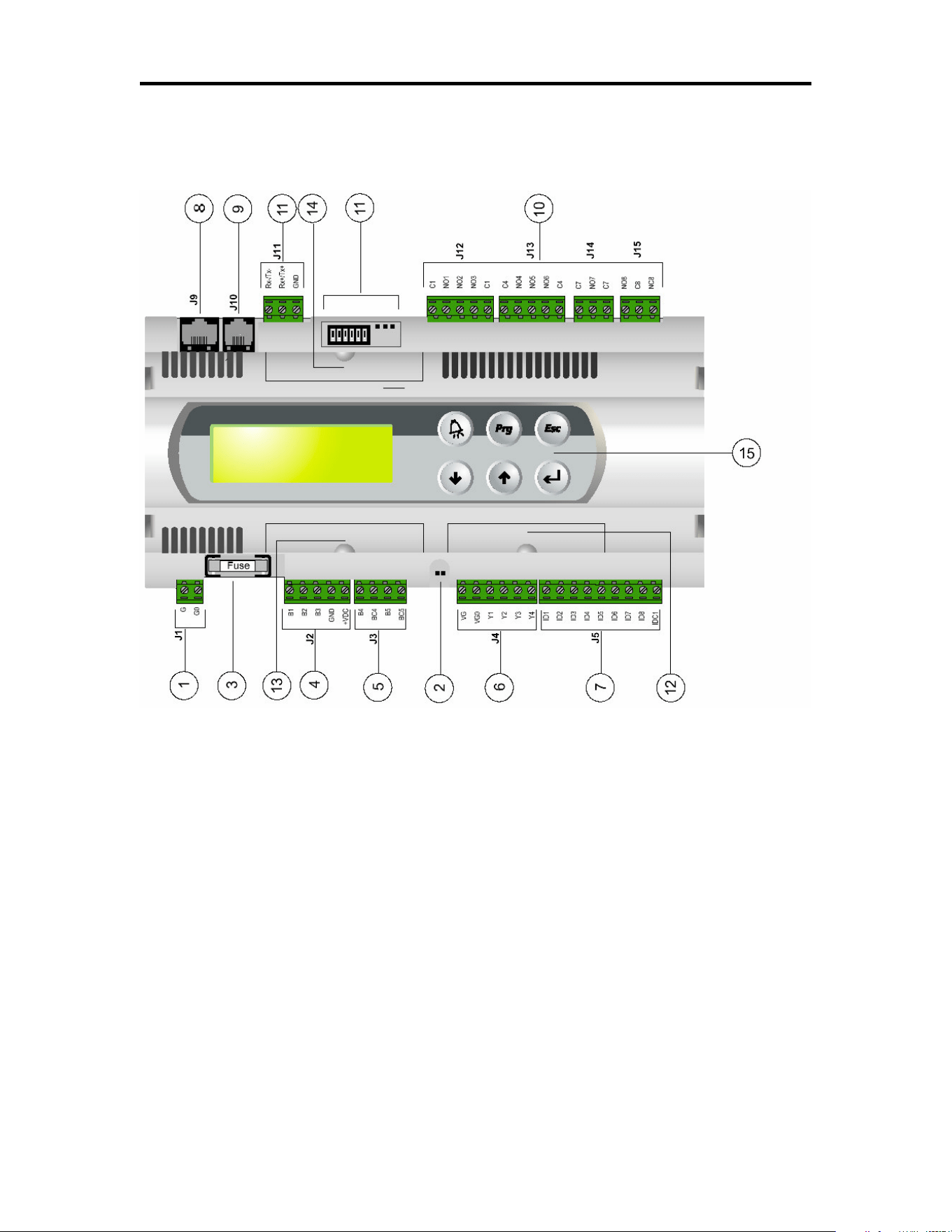
Technical Specifications
Legend
1. power supply connector [G (+), G0 (-)]
2. yellow LED indicating mains power and red LED for alarms
3. 250Vac, 2A slow-blow fuse (T2A).
4. universal analog inputs NTC, 0/1V, 0/10V, 0/20mA, 4/20mA
5. passive analog inputs NTC, PT1000, ON/OFF
6. analog outputs 0/10V
7. 24Vac/Vdc digital inputs
8. connector for synoptic terminal (external panel with direct signaling)
9. connector for all pCO 2 series standard terminals and for the application program download
10. relay digital outputs
11. connector, addressing and LED for pLAN local network
12. hatch for inserting RS485 serial card for supervisor or RS232 serial card for modem interfacing
13. hatch for inserting the card for connection to a parallel printer
14. hatch for inserting the FLASH-MEMORY expansion card
15. built-in terminal (LCD, buttons and LEDs)

PROGRAMMABLE CONTROLLER
Version 4.0 Page 22 113635e
Mechanical Specifications
Dimensions SMALL board models can be mounted on 13 DIN modules, 110x227.5x60mm
MEDIUM and LARGE board models can be mounted on 18 DIN modules,
110x315x60mm
Mounting on DIN rail
terminal block with removable-screw male/female connectors or removable pitch header connectors
according to the customer requirements – max. voltage: 250Vac - cable cross-
section: min. 0.5mm
2
– max.2.5mm
2
Plastic Case
• it can be fastened on DIN rail according to DIN 43880 and CEI EN 50022 standards
• material: technopolymer
• self-extinguishing: V0 (complying with UL94) and 960°C (complying with IEC 695)
• ball pressure test :125°C
• comparative tracking index:250V
• color: RAL7035 gray or anthracite gray
• cooling vent-holes
Electrical Specifications
power (controller with terminal connected) 22÷40Vdc and 24Vac ±15% 50/60Hz - P= 20W
maximum absorption
CPU H83002, 16 bit and 16MHz
program memory (on FLASH MEMORY) 1 Mbyte organized in 16 bit (it can be expanded
up to 6 Mbyte)
data memory (static RAM) 256 kbyte organized in 16 bit (it can be expanded
up to 1 Mbyte)
parameter data memory 2 kbyte organized in 16 bit (maximum limit:
400.000 writes per memory location)
operating cycle (with applic. of average complexity) 0.5s (typical value)
Analog Inputs
analog conversion 10 bit A/D converter, built-in CPU
type passive: NTC temp. probe, (-50÷100°C; R/T
10k½ ± 1% at 25°C - B 25/80 =3,435°K±1%; step
measurement), PT1000 (-100÷200°C; R/T
1000½/°C; step measurement) or free digital input,
selected via software (B4, B5 inputs)
universal: NTC temp. probe (see passive
type), voltage: 0÷1Vdc or 0÷10Vdc>;
current: 0÷20mA or 4÷20mA, selected via software
(B1, B2, B3 inputs)
time constant for each input 0.5s
WARNING: for powering any active probe it is possible to use the 21Vdc at +Vdc terminal; the max.
current that can be
deli-vered is 200mA thermally protected against short circuits.
Digital Inputs
Type 24Vac optically insulated
.
Analog Outputs
Type 0÷10Vdc optically insulated
power external 24Vac/Vdc
resolution 8 bit
max. load 1k½ (10mA)

PROGRAMMABLE CONTROLLER
Version 4.0 Page 23 113635e
Digital Outputs
Type relay
They are grouped in 3 with two common pole terminals in order to assemble the common poles easily. Be
careful to the current flowing in common terminals, because it must not exceed the rated current of each
single terminal, that is: 8A resistive for removable-screw terminals and 6A resistive for removable pitch
header terminals. The relays are divided into groups, according to the insulating distance. Inside each group
the relays have their single own insulation, so they must be exposed to the same voltage (in general 24Vac
or 230Vac). Among the groups there is double-insulation, therefore the groups can be of different voltage.
Anyway the double-insulation does exist toward the rest of the controller and its presence is guaranteed
among digital output terminals.
Groups 1, 2, 3, 4, 5, 6, 7 - 8 (alarm relay)
NO contacts all with 250Vac varistor protection
switch contacts 5 with 250Vac varistor protection on both contacts
commutable power 2500VA, 250Vac, 8A resistives, 2A FLA, 12A LRA
according to UL873 2A resistives, 2A inductives,
cosj=0,4, 2(2) according to EN 60730-1
Other Specifications
storage conditions -20T70, 90%r.H. non-condensing
operating conditions -10T60, 90%r.H. non-condensing
index of protection IP20, IP40 (front panel only)
environmental pollution normal
Classification according to
protection against electric shock should be integrated into Class 1 and/or 2 devices
PTI of insulating materials 250V
period of electric stress across insulating parts long
type of actions 1C
type of disconnection or microinterruption microinterruption
category of resistance to heat and fire D (UL94 - V0)
immunity against voltage surges category 1
no. of automatic operating cycles (e.g.: relay) 100,000
software Class and structure Class A
device is not intended to be and hand-held
According to the limits quoted on the Safety Standards relevant to electromagnetic compatibility (see
conformity declaration published on the installation manual), rare malfunctioning is founded only on
display and LED indications. LEDs and display are restored when the disturb ends.

PROGRAMMABLE CONTROLLER
Version 4.0 Page 24 113635e
Ramp and Soak Worksheet
Program #
Daily/Weekly Time Temp. Humidity Lights Ramp/Hold
1
2
3
4
5
6
7
8
9
10
11
12
13
14
15
16
17
18
19
20
21
