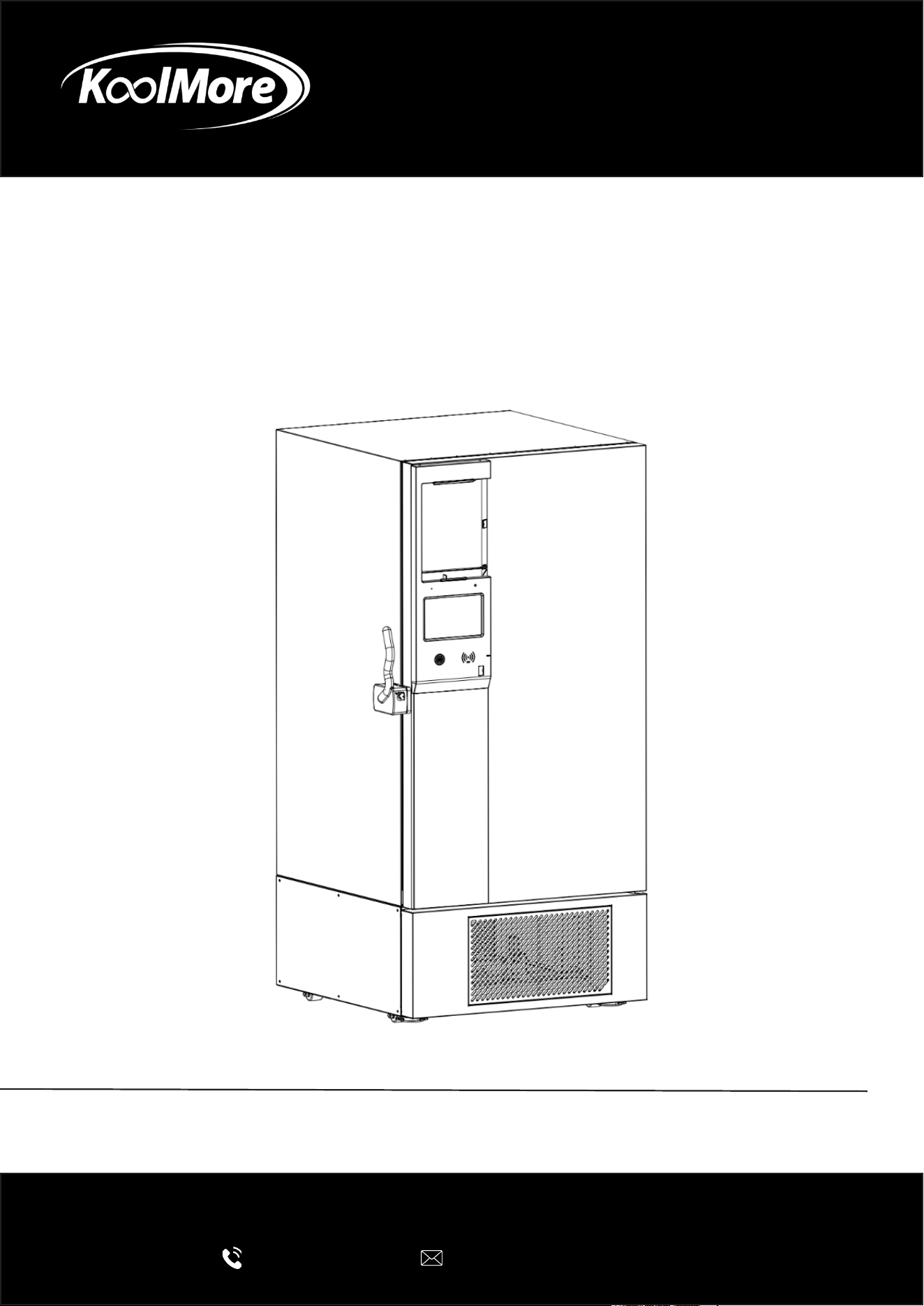
LAB FREEZER
Dual Inverter Ultra Low Temperature
Lab Freezer
USER MANUAL
Before using, please read the operating instructions carefully to
ensure proper application and achieve satisfactory results.
For any service related issues, please contact us:
718-576-6342
support@koolmore.com
Models: KM-PHF-20CUL, KM-PHF-25CUL, KM-PHF-30CUL
Stay informed with the latest information for your
KoolMore Appliance.
Scan the QR code below to access the most recent user manual
on our website, which is constantly being updated and improved.
If you need any assistance or have questions, our customer support
team is here to help.
Phone- 718-576-6342 Email- support@koolmore.com
Please write down the model number and serial number below for future reference. Both numbers are located on the
rating label on the back of your unit or inside of the unit and are needed to obtain warranty service. You may also
want to staple your receipt to this manual as it is your proof of purchase and may also be needed for service
under warranty.
Model Number:
Serial Number:
Date of Purchase:
To better serve you, please do the following before contacting customer service:
If you received a damaged product, immediately contact the retailer or dealer that sold you the product.
Read and follow this User Manual carefully to help you install, use, and maintain your unit.
Refer to the Troubleshooting section of this manual as it will help you diagnose and solve many common issues.

Contents
Safety ............................................................................................. 5
Before Use ...................................................................................... 9
Installation ...................................................................................... 11
Parts ............................................................................................... 16
Operations ...................................................................................... 18
Maintenance ................................................................................... 42
Specification ................................................................................... 44
Packing List .................................................................................... 45
Diagram ......................................................................................... 46
Troubleshooting .............................................................................. 48
Warranty ......................................................................................... 49
WARNING: Flammable material.
WARNING: Low temperature/freezing conditions, frostbite HAZ-
ARD(MOD).
WARNING: Electrocution Hazard.
WARNING: Crushing of hands.
Frostbite Waring.
Warning.
Cyclopentane Foam

Safety
Please carefully read the
following information to better understand the Operating Instructions and use this
product, so as to prevent personal injury and damage to items.
WARNING: Flammable refrigerant is is used in this product.
This unit is intended for use in commercial, industrial, or institutional occupancies as defined in
the Safety Standard for Refrigeration Systems, ANSI/ASHRAE 15.
Parts Replacement and Servicing
These installation and operating instructions require that any component parts be replaced only
with identical or approved equivalents, and that all servicing be performed by authorized person-
nel. This ensures proper operation and reduces the risk of ignition caused by incorrect parts or
improper service.
WARNING: Ensure all ventilation openings are not obstructed.
WARNING: Do not use mechanical devices or other means to accelerate the defrosting process,
other than those recommended by the manufacturer.
WARNING: Do not damage the refrigerant circuit.
WARNING: The packaging base at the bottom of the unit must be removed before use.
WARNING: When moving the unit, take care that the bottom foot does not touch the power cord.
WARNING: The bottom front wheel brake of the unit needs to be locked after moving to the desig-
nated position.
WARNING: Before using this unit for the first time, allow it to stand upright for at least 12 hours
before plugging it in.
WARNING: After connecting the unit to the power supply, do not load items immediately. Allow
the unit to run until the internal temperature reaches the set operating temperature, then add items
gradually in batches.
Refrigerant and the cyclopentane foam insulation used in this unit are flammable. When disposing
of the unit, keep it away from all ignition sources and ensure it is handled by a licensed recycling or
recovery company. The unit must not be incinerated, as improper disposal can cause environmen-
tal harm or create safety risks.
The safety of any system that incorporates this equipment is the responsibility of the system’s
assembler.
IMPORTANT: It is the consumer’s responsibility to comply with Federal and Local regulations
when disposing of this product.
WARNING: To reduce the risk of fire or flammability hazards, installation of this unit must be per-
formed only by a suitably qualified and authorized technician.
DANGER: Risk of Fire or Explosion. Flammable Refrigerant Used. To Be Repaired Only By Trained
Service Personnel. Do Not Puncture Refrigerant Tubing.

CAUTION: Risk of Fire or Explosion. Flammable Refrigerant Used. Consult Repair Manual / Own-
er’s Guide before attempting to install or Service This Equipment. All Safety Precautions Must be
Followed.
WARNING: Using the equipment in any way not specified by the manufacturer may compromise
its safety features and void the warranty.
Product Overview
Structure
Primarily consists of refrigeration system, electrical control and alarm system, cabinet, and door
body.
Scope of Application
Applicable to the low-temperature storage of human examination samples, drugs, vaccines, biolog-
ical products, reagents, plasma and other samples stored in medical institutions, blood stations,
scientific research institutions and other departments under low temperature conditions.
Refrigeration System
Mainly composed of compressor, condenser, dryer filter, capillary tube, and evaporator.
Safety Precautions
WARNING:
Ignoring WARNING items may result in serious injury or death.
CAUTION:
Ignoring CAUTION items may result in minor injury or damage to the unit or surrounding property.
Prohibited Actions:
Acts or operations that must not be performed.
Required Actions:
Actions or operations that must be followed to ensure safe use.
CAUTION: Disposal Safety
• Dispose of the appliance in accordance with federal and local regulations.
• The appliance contains flammable refrigerant.
CAUTION: Handling Precautions
• Risk of fire or explosion if the refrigerant tubing is punctured.
• Follow handling instructions carefully.

• Do not store flammable, explosive, or volatile materials in the unit, and do not use flammable
sprays near it. Doing so may result in fire or explosion.
• Do not store corrosive chemicals such as acids or alkalis inside the freezer. These substances
can damage internal components and electrical parts.
• Keep plastic packaging bags out of the reach of children to prevent suffocation hazards.
• Do not climb on the unit or place heavy objects on top of it. The freezer may tip over and cause
injury or property damage.
• Do not use this product outdoors. Exposure to rain can cause electrical shock or electrical
leakage.
• Do not place the unit in areas with high humidity or where it may be splashed with water. Ex-
cess moisture can reduce insulation and lead to electrical shock.
• Do not pour water directly onto the freezer. This may cause electrical shock or a short circuit.
• Never attempt to disassemble, repair, or modify the unit on your own. Improper service can
cause fire, electrical shock, or injury.
• Do not connect the grounding wire to gas pipes, water pipes, telephone lines, or lightning rods.
Incorrect grounding may result in electrical shock or other hazards.
• Do not touch the power plug or operate switches with wet hands, as this can cause electrical
shock.
• Do not place containers of liquid or heavy items on top of the unit. Spilled water can cause
electrical leakage, and falling objects may cause injury.
• Never insert metal objects such as nails, wires, or tools into vents, gaps, or air outlets. This may
result in injury or electric shock from contact with moving or live components.
• Do not drag, pull, twist, bind, or damage the power cord. A damaged cord or plug may cause
fire or electric shock.
• Do not use the unit with a loose or damaged power plug, as this can cause fire or electrical
shock.
• Do not store glass bottles or canned items in the freezer. They may freeze, crack, and cause
injury.
CAUTION:
• Keep the area around the unit clear to ensure proper airflow and ventilation.
• After a power outage or shutdown, verify that the temperature setpoint and settings are correct
before restarting the freezer. Incorrect settings may damage stored materials.
• After the freezer is turned off or an outage, wait at least 5 minutes before turning the freezer
back on to prevent compressor or system damage.
• Clean the air filter at least once per month. A dirty filter can cause temperature instability or
system malfunction.
• If the power plug becomes dusty, clean it promptly. Dust buildup can cause poor connections,
overheating, or even fire.
• Wear gloves during maintenance to avoid injury from sharp edges or corners.
• Do not touch stored items or interior surfaces with bare hands. Direct contact with frozen ma-
terials or inner walls may cause frostbite.
• Use the door handle when closing the door to prevent finger pinching.

• When moving or transporting the unit, do not tilt it more than 30° to avoid damaging internal
components.
• During product handling, care should be taken not to trip over it to prevent damage to the prod-
uct or personal injury.
• Do not use the door handle to lift or carry the product to avoid damage to it or personal injuries.
• Do not damage the refrigeration circuit.
• Do not use appliances inside the product except for those recommended by the manufacturer.
NOTICE! Risk of Damage:
Vacuum insulation panels are used in the construction of these ULT freezers. Inspect the cabinet
panels for punctures or other damage that compromises the integrity of the product
These panels are mounted in the cavity against the steel outer wall of the freezer. Any drilling or
puncture to the outer wall could release the vacuum from the panel, resulting in impaired freezer
performance.
Any unauthorized punctures or intentional damage to the cabinet walls will void the warranty.
WARNING: Dispose of the refrigerator in accordance with local regulations, as it contains flamma-
ble blowing agents and refrigerant.

Usage Guidelines
• When the unit is running, the front area near the outer door may feel warm. This is normal and
is caused by built-in anti-condensation components designed to prevent moisture buildup on
the exterior surface.
• Before loading items, make sure the internal temperature has reached the setpoint. Add items
in small batches, ensuring each load is no more than one-third of the compartment volume to
avoid excessive temperature rise.
• The displayed temperature reflects the reading at the sensor location inside the cabinet. When
the unit first starts, the displayed value may differ slightly from the internal center temperature.
After the unit stabilizes, the displayed temperature will closely match the actual temperature.
• Some models include a test port for inserting temperature probes. After removing the probe
or test lead, seal the test port with insulation material. Failure to do so may prevent the freezer
from reaching the set temperature and can cause condensation around the port.
• Clean the unit using a diluted neutral cleaner. Do not use brushes, acids, gasoline, abrasive
powders, polishing agents, or hot water, as these may damage painted, plastic, or rubber com-
ponents. Never use volatile solvents (such as gasoline) on plastic or rubber parts.
• If the freezer will not be used for an extended period, disconnect the power and turn off the
battery switch.
• Minimize the amount of time the door is open when loading or removing items to help maintain
stable compartment temperature.
• After the door is opened, a brief temperature rise inside the compartment is normal. The tem-
perature will return to the setpoint once the door is closed and the unit resumes normal opera-
tion.
• Over time, frost may form on the interior walls. If the frost layer reaches approximately 5 mm,
defrost the unit using the provided plastic scraper. Excessive frost reduces cooling efficiency
and increases energy consumption.
• Before defrosting, remove all stored items and place them in an environment that maintains
their required storage temperature.
• Do not use sharp tools such as knives, chisels, or screwdrivers to remove frost. These can
damage the refrigerant coils or inner liner, leading to product failure. Always avoid scratching
the interior surfaces during defrosting.
• The enclosure can only be opened with tools, and repairs must be performed exclusively by
qualified technicians or authorized after-sales service personnel. Unauthorized access or ser-
vicing may result in electric shock, fire, or serious injury.
Handling
1. Use proper equipment when moving the unit. Transport the product with a manual hydraulic
pallet truck or similar appropriate lifting device to prevent damage.
2. Remove all packaging. Take off all packing materials, including the bottom cushion, before
moving the unit into the building for placement.
3. Allow the unit to settle. After positioning the freezer in its final location, wait 24 hours before
powering it on to ensure proper compressor oil return and stable operation.
Before Use
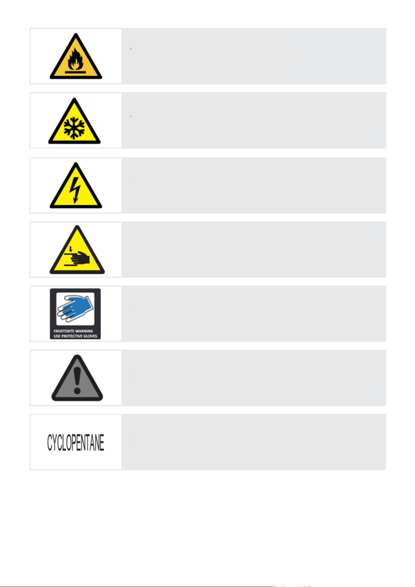
Door Space Requirements
The unit’s door must be able to open fully as shown.
W×D≥68.90 in*76.77 in (for KM-PHF-20CUL)
W×D≥65.75 in*62.99 in (for KM-PHF-25CUL)
W×D≥54.92 in*59.06 in (for KM-PHF-30CUL)

Installation
Installation Environment
• This product is designed for indoor use only and must not be installed outdoors.
• Ambient Operating Temperature: 10°C–32°C (50°F–89.6°F).
The optimal operating range is 18°C–25°C (64.4°F–77°F). Use air conditioning if needed to
maintain this range.
• Ambient Humidity: Below 80% RH. At the maximum temperature of 32°C (89.6°F), humidity
should be kept below 60% RH.
• Pollution Degree: Level 2. Avoid environments with excessive dust.
• Power Supply Environment: Overvoltage Category II.
• Avoid installing the unit in locations with mechanical vibration or movement.
• Maximum Installation Altitude: Below 2,000 m (6,562 ft).
• Input Voltage: AC 100–240V ±10%, 50/60 Hz.
• This product is sensitive to ambient conditions. If the environment does not meet the above re-
quirements, the freezer may not operate normally. Improve the installation environment before
use.
• Transportation and Storage Conditions:
• Ambient Temperature: –40°C to +55°C (–40°F to 131°F)
• Humidity: 10%–90% RH
Installation Site
• Do not install the unit in a confined or enclosed space. The doorway to the room where the
biomedical freezer is installed must be large enough to allow normal access and removal of
the equipment. Restricted access can make maintenance difficult and may result in damage to
stored items if the unit cannot be serviced promptly in the event of a failure.
• The installation surface must be solid, level, non-combustible, and capable of supporting the
full weight of the equipment during operation.
• Choose a location with good ventilation and no direct sunlight.
• Each unit must be connected to its own dedicated power outlet.
• For 220V, the outlet must support 10A or more.
• For 115V, the outlet must support 14A or more.
Ensure the plug fits securely and firmly into the socket.
• Verify the working voltage before use.
In regions with unstable voltage, use a voltage stabilizer rated for the equipment’s load and
above 10 kW to ensure the input voltage remains within the required range.
• The equipment must be properly grounded.
If the power outlet includes a grounding terminal, ensure it is correctly connected.
If not, a qualified technician must install a proper grounding connection.
WARNING
• Do not connect the grounding wire to gas pipes, water pipes, telephone lines, or lightning rods.
Improper grounding can result in electrical shock or serious hazards.
• The power plug must remain accessible after installation so it can be quickly unplugged in an
emergency.
• Do not block the ventilation openings of the product.
CAUTION!
The ambient environment has a significant effect on the performance of this equipment. If the
installation conditions do not meet the required specifications, the unit may not operate properly.
Improve the surrounding environment before using the equipment.
Please also note that the unit operates on an intermittent refrigeration cycle, which is normal for
this type of system.
Preparations Before Use
1. Remove all transport packaging materials and packaging straps (including protective foam in
the packaging box).
2. Check the accompanying accessories. Please check the items inside with reference to the
packing list. If there is any discrepancy, Please contact the company you purchased it from or
KoolMore Customer Service promptly.
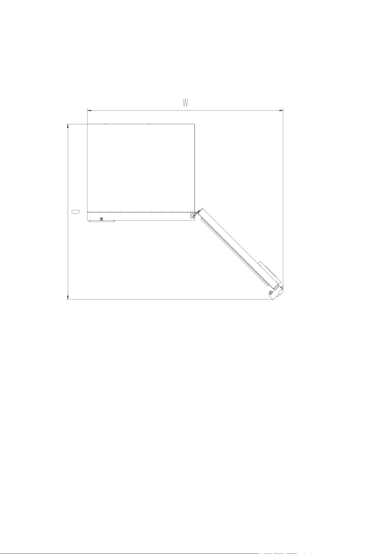
3. Placement conditions: Ensure at least 11.8 in. clearance around all sides of the product for
proper ventilation and heat dissipation.
4. To remove the product from the wooden shipping base, first remove the 16 screws that secure
the wooden support boards—eight screws on each side at the front and back. Once the screws are
removed, gently push the freezer to one side so that the unit separates from the wooden support
on that side. Slide the wooden support out and allow that side of the unit to lower carefully to the
floor. Then repeat the process on the opposite side: push the unit slightly to separate it from the
remaining wooden support, pull the support out, and lower the unit fully onto the ground. After
both supports are removed, the product will be completely freed from the wooden base.
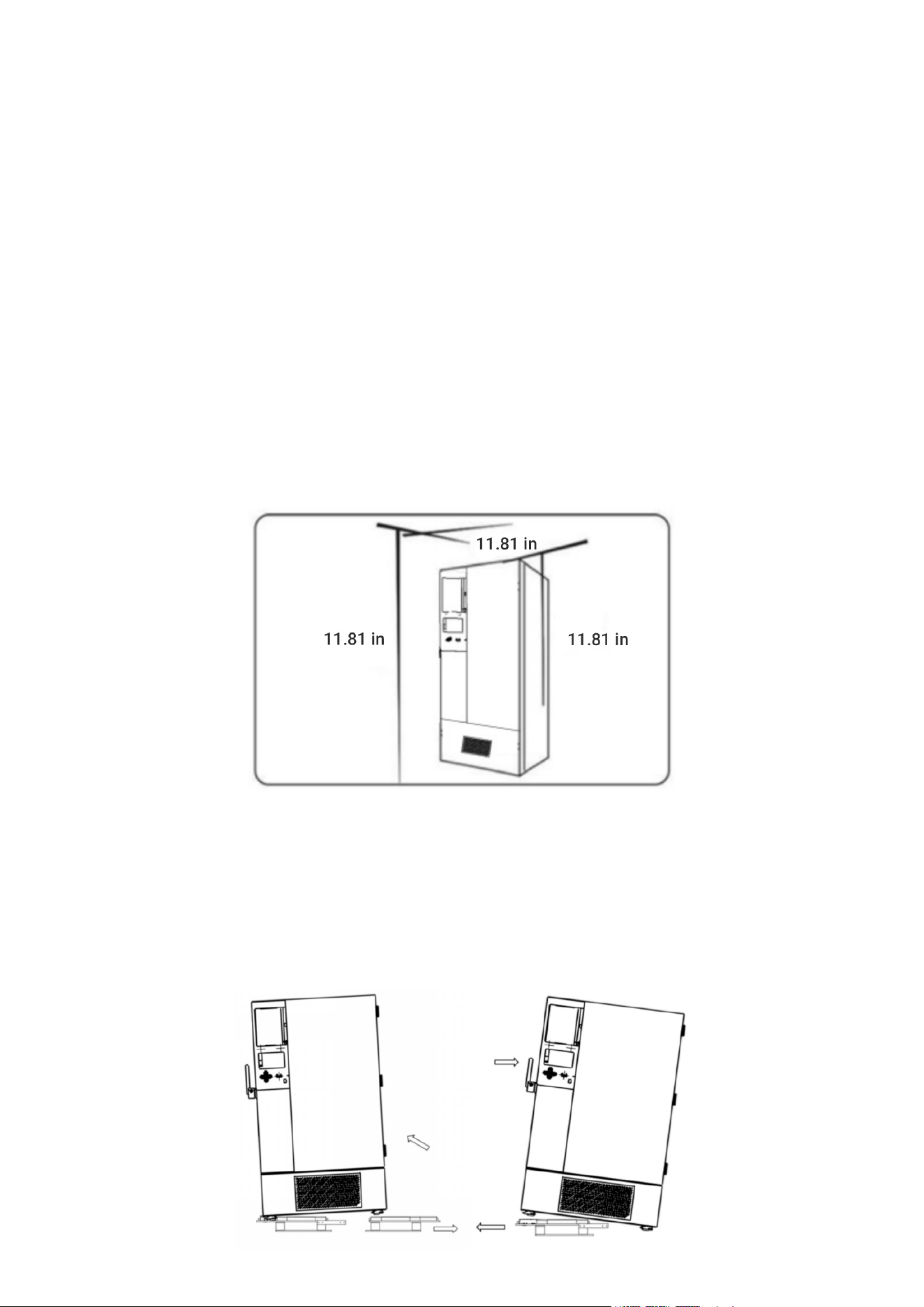
5. This product is equipped with universal wheels, allowing it to move forward, backward, left, and
right for easy positioning. Once the unit is in the desired location, secure it by adjusting the leveling
feet. Rotate the leveling feet upward or downward as needed to keep the product stable and prop-
erly leveled.
6. Open the outer door to more than 90°, remove the shelves from the bottom of the freezer, take
off the protective film, and then place the shelves one by one onto the shelf support rails.
WARNING
Keep the plastic packing bag out of the reach of children to prevent the risk of suffocation.
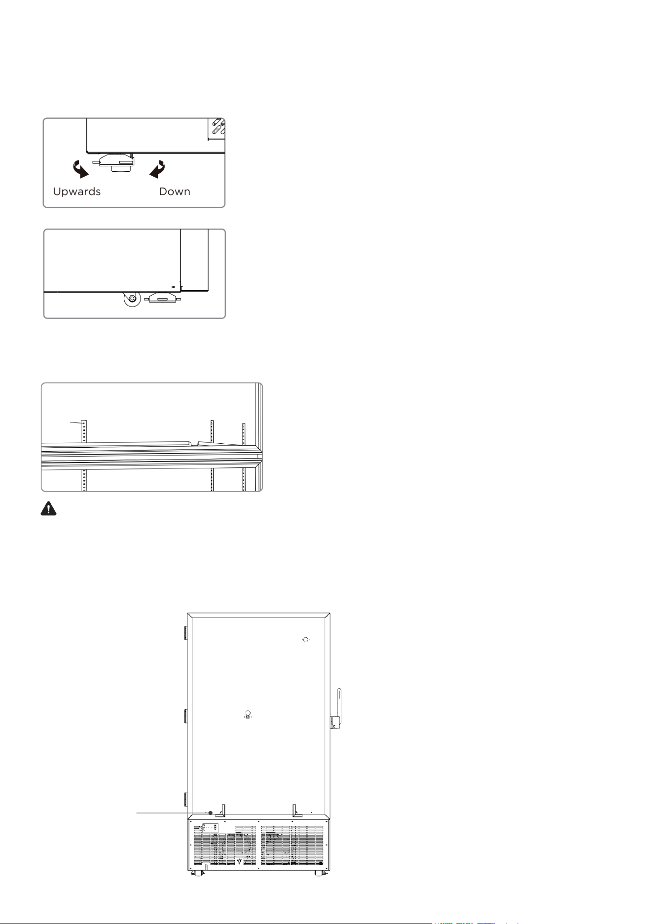
7. Remove the back-spacing brackets from inside the cabinet and attach them to the rear of the
unit using the provided screws. These brackets ensure proper clearance from the wall and prevent
the freezer from being pushed too far back.
Spacer bracket

Inital Startup
When using the product for the first time, follow the steps below:
• After positioning, leveling, and cleaning the unit, allow it to stand for at least 24 hours before
powering it on to ensure proper operation of the compressor.
• Connect the power cord to a dedicated outlet that meets the required electrical specifications,
and ensure the unit is connected under no-load conditions (with nothing inside).
• After plugging in the unit, switch on the product’s circuit breaker. If the model includes a back-
up battery, turn on the battery switch located at the lower rear of the unit. Once activated, the
battery will begin charging automatically.
• Set the desired temperature (factory default is –81°C). Do not place any items inside at this
stage. Allow the freezer to run and confirm that it can reach and maintain the set temperature.
Observe the unit for at least 24 hours to ensure stable performance.
• After confirming stable operation, load items in batches, with each batch not exceeding one-
third of the freezer’s total volume. Ensure that the freezer can return to normal operating tem-
perature for at least 8 hours before adding the next batch.
• Minimize door openings during the initial cooling cycle, as this will cause the internal tempera-
ture to rise.
• Note: Over-temperature alarms are disabled for the first 8 hours after the initial power-on.
Backup Battery
• This product is equipped with a backup battery. The battery switch is located on the lower left
side of the rear panel.
• When the switch is turned ON, the unit will automatically charge the backup battery whenever
the freezer is powered.
• When the switch is turned OFF, the battery will not charge even if the unit is powered.
• Once the battery is fully charged, charging stops automatically—no user action is required.
Frame Heating Function
This model includes a frame heating function, which automatically activates in response to chang-
es in ambient humidity. Its purpose is to prevent condensation around the door frame and cabinet.
No user operation is required.
After a Power Failure
The unit automatically remembers the temperature setpoint and all operating parameters. When
power is restored, the freezer will resume operation using the same settings that were active be-
fore the power outage.
WARNING
• If the product is unplugged or the power to the biomedical freezer is interrupted, do not restart
the biomedical freezer for at least 5 minutes to avoid damage to the compressor or system.
• When the product is going to be left unused for a long time, unplug the power plug and turn off
the battery switch (applicable to products with batteries) to prevent electric shocks, electric
leakages, or fire due to aging of the power cord.
• If the product is to be stored unused in an unsupervised area for a long period, ensure that chil-
dren do not have access to the product and that doors cannot be closed completely.

• The unit should be monitored by a designated responsible person who checks the operation
regularly and records the temperature and status at least once every 2–4 hours. In the event
of a malfunction or shutdown, the internal temperature will rise. If the unit cannot be repaired
promptly, transfer stored items immediately to another storage location that meets the required
temperature conditions to prevent loss or damage.
• This product is an ultra-low temperature freezer. Always verify that the required storage tem-
perature for your materials matches the freezer’s temperature range to prevent damage or
economic loss due to incorrect storage conditions.
• Because of normal refrigeration system behavior, the displayed temperature may differ slightly
from the actual temperature inside the chamber. This is expected and does not indicate a mal-
function.
• Do not load large quantities of warm items at once. Adding too many warm items can cause
prolonged compressor operation, slow temperature recovery, and reduced compressor life.
Always load items in small batches, allowing the temperature to drop until the required tem-
perature is reached.
• Do not damage the refrigeration circuit under any circumstances.
• Do not place unauthorized or uncertified electrical devices inside the freezer.
• Do not use mechanical tools or unapproved methods to speed up the defrosting process. Only
follow the manufacturer’s approved defrosting procedures.
Parts
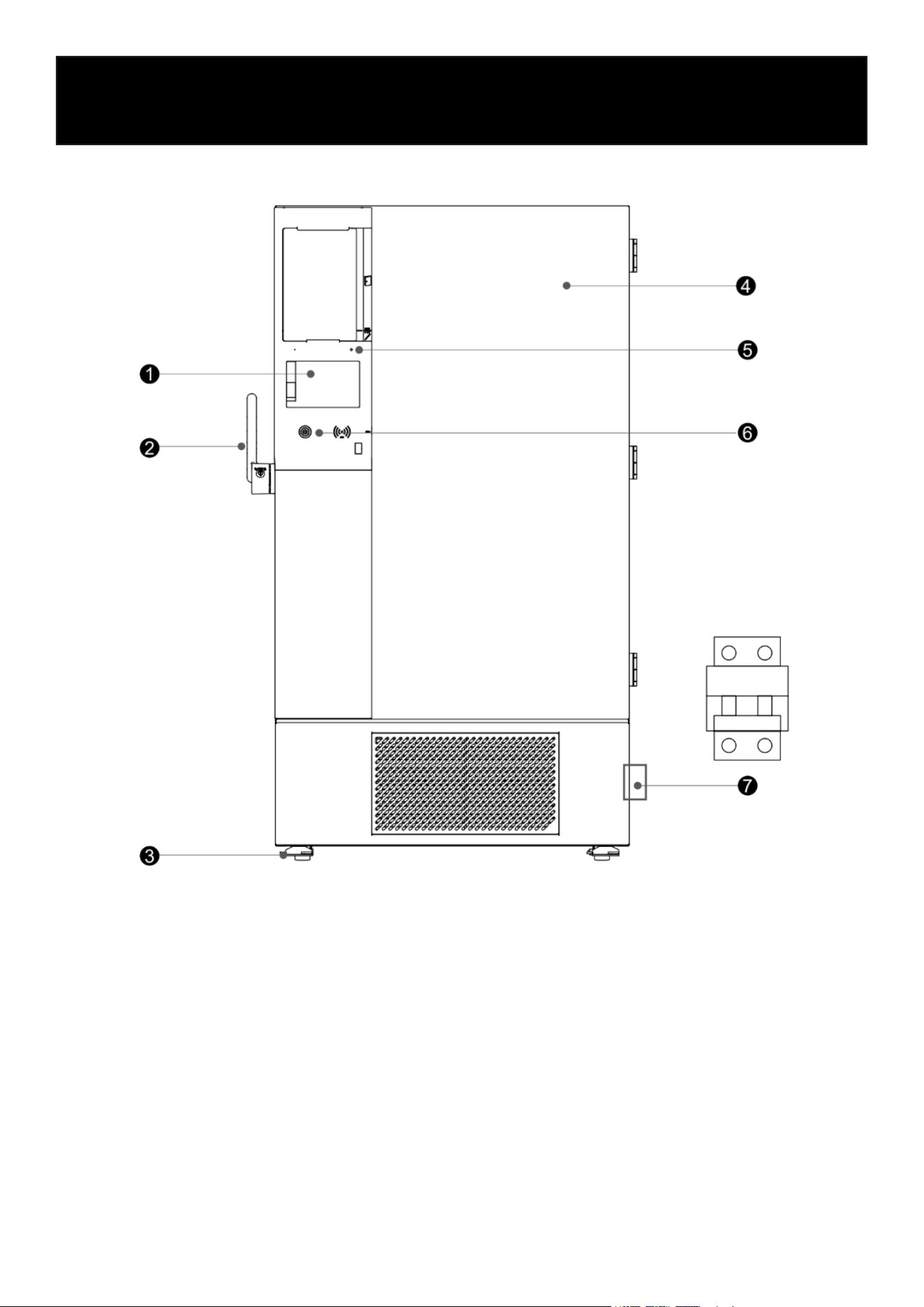
Schematic Diagram of Appearance
Schematic Diagram (front view and partial view)
1. Control Panel
2. Outer Door Handle
3. Universal Wheel
4. Door Assembly
5. State Indicator
6. Balance Valve
7. Miniature Circuit Breaker
Due to ongoing product improvements and variations between models, the actual product may
differ slightly from the diagrams shown. Always refer to the actual unit for accurate details.
The diagrams are intended only as a general reference for identifying functional parts.
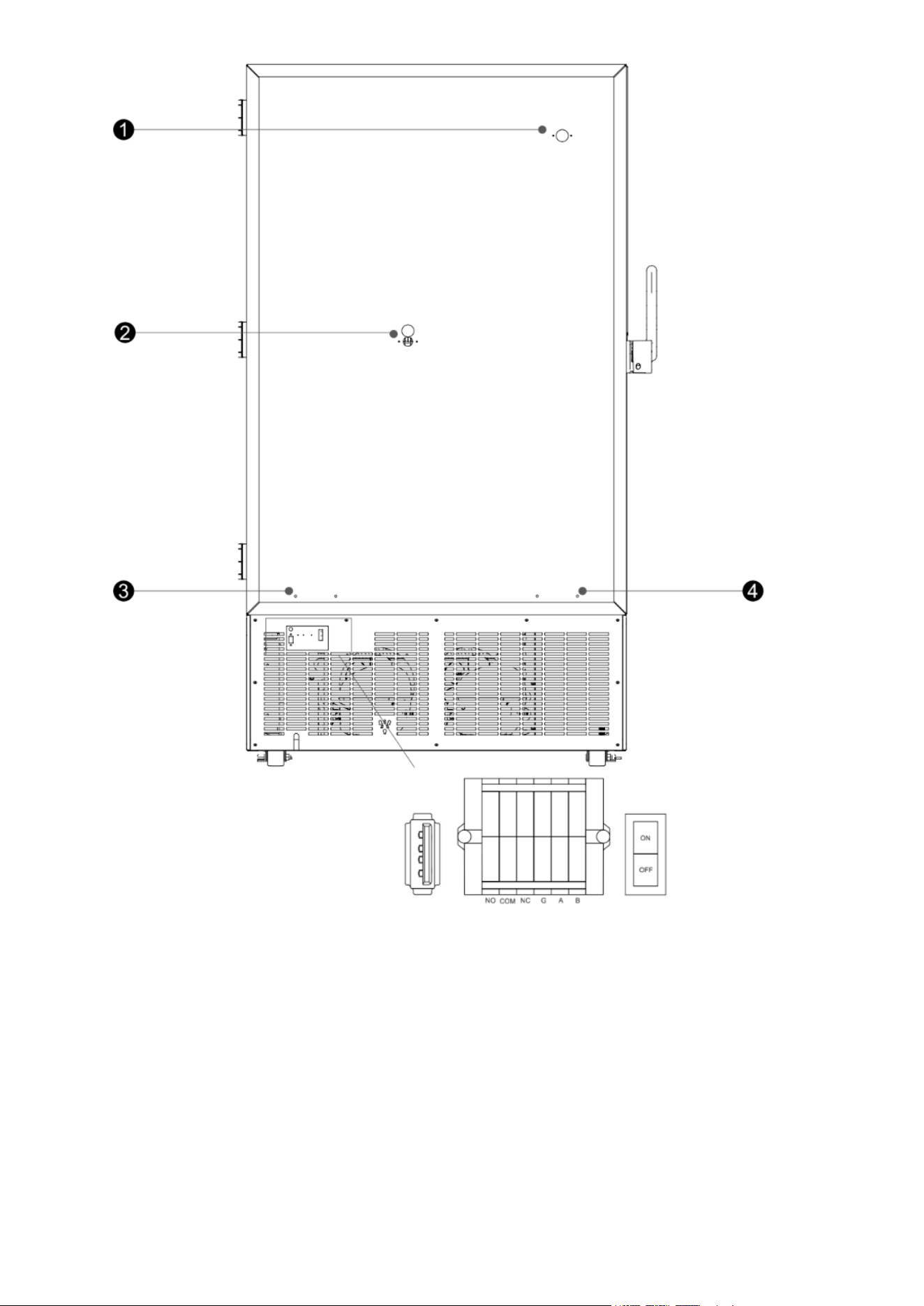
Schematic Diagram (rear view and partial view)
5V power
supply
Remote alarm/RS485
port
Back battery
switch port
1. Testing Hole 1
2. Testing Hole 2
3. Limit Bracket Mounting Hole 1
4. Limit Bracket Mounting Hole 2
Due to ongoing product improvements and variations between models, the actual product may
differ slightly from the diagrams shown. Always refer to the actual unit for accurate details.
The diagrams are intended only as a general reference for identifying functional parts.
Operations
Create a User
1. When using the machine for the first time, you must create user accounts.
Two account types are available:
• Administrator account (Level 1)
• Standard user account (Level 2)
The administrator has full access to all settings and system functions.
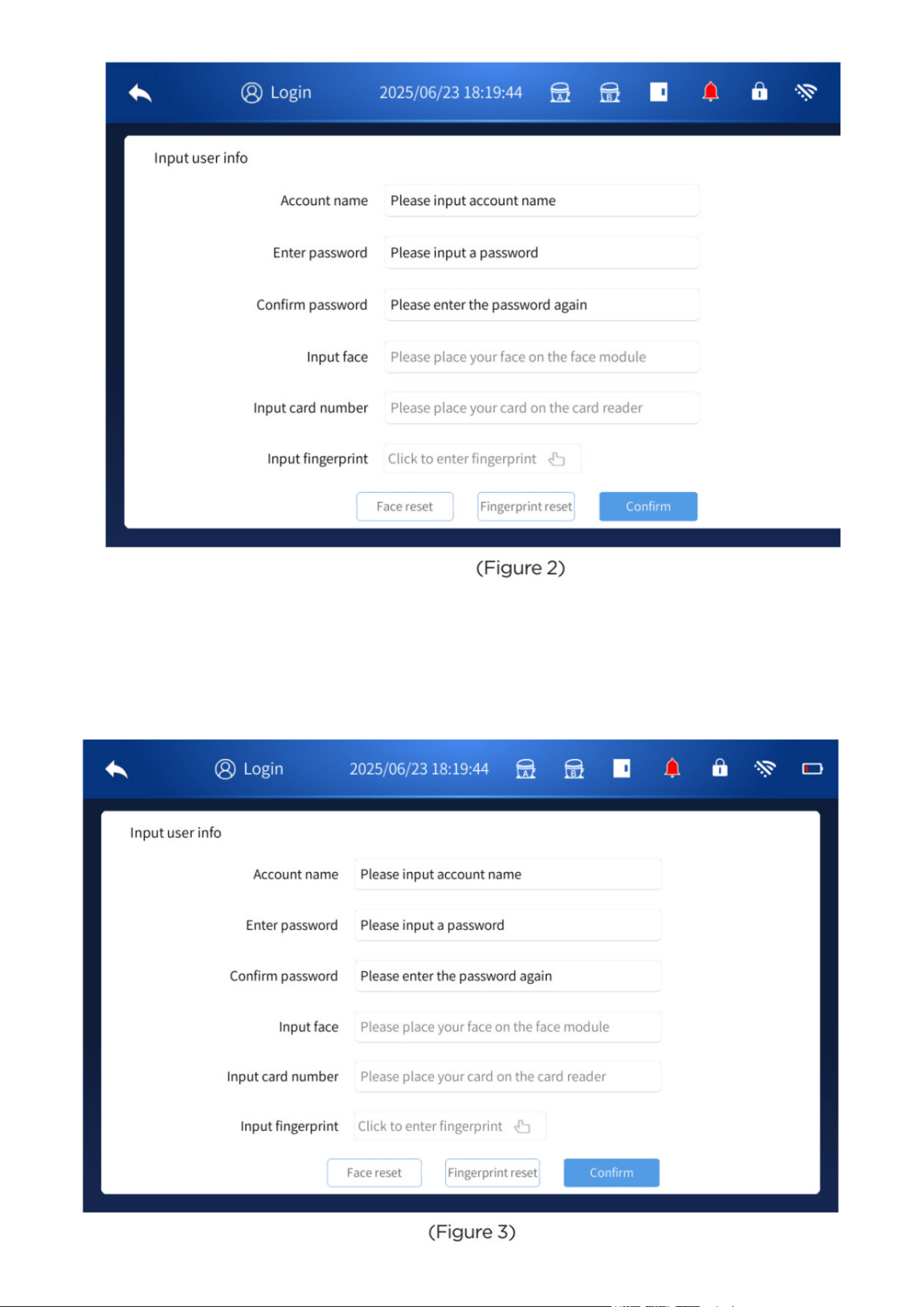
1.1 Add Administrator
After the machine starts up:
Tap the Settings icon at the bottom of the home screen and then tap User Setting to enter the
user creation interface.
(See Figure 1.)
In the permissions area, select Administrator for the account type.
Enter the required information:
• Account name
• Password
• Confirm password
Tap Confirm to complete the administrator setup.
(See Figure 2)
1.2 Adding Common User
You must be logged in to the administrator account before creating an common (Level 2) user.
Multiple ordinary user accounts may be created as needed.
Note: Passwords must be 8–16 characters in length.
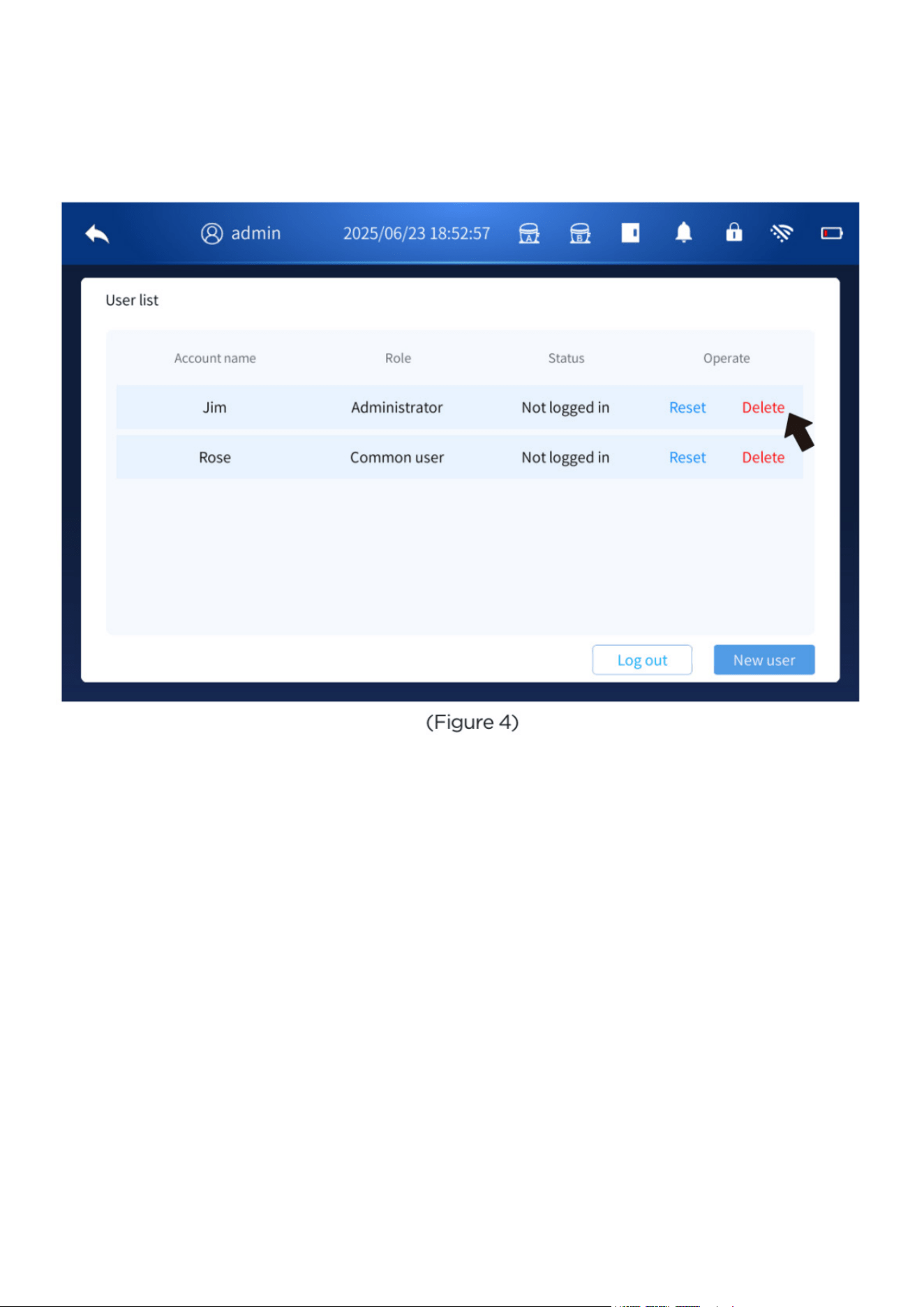
1.2 Delete User
After logging in with the administrator account, go to the user settings page. Select the account
you want to remove and click the corresponding Delete button.
Please note that Common (Level 2) users do not have permission to delete other user accounts.
1.3 Modify / Reset Password
All users can open the user list page while logged in to modify or reset their passwords.
Administrator Mode:
Click the Reset button next to a common user’s name to reset that user’s password.
After resetting, the password will be 12345678.
Any Common Account:
When logged in, click the Edit button next to your own user name to change your password.
Passwords may include letters, numbers, and symbols.
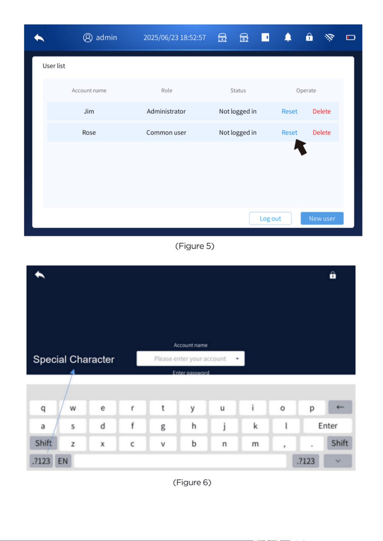
Note: Password modification or reset can only be performed while the user is logged in.
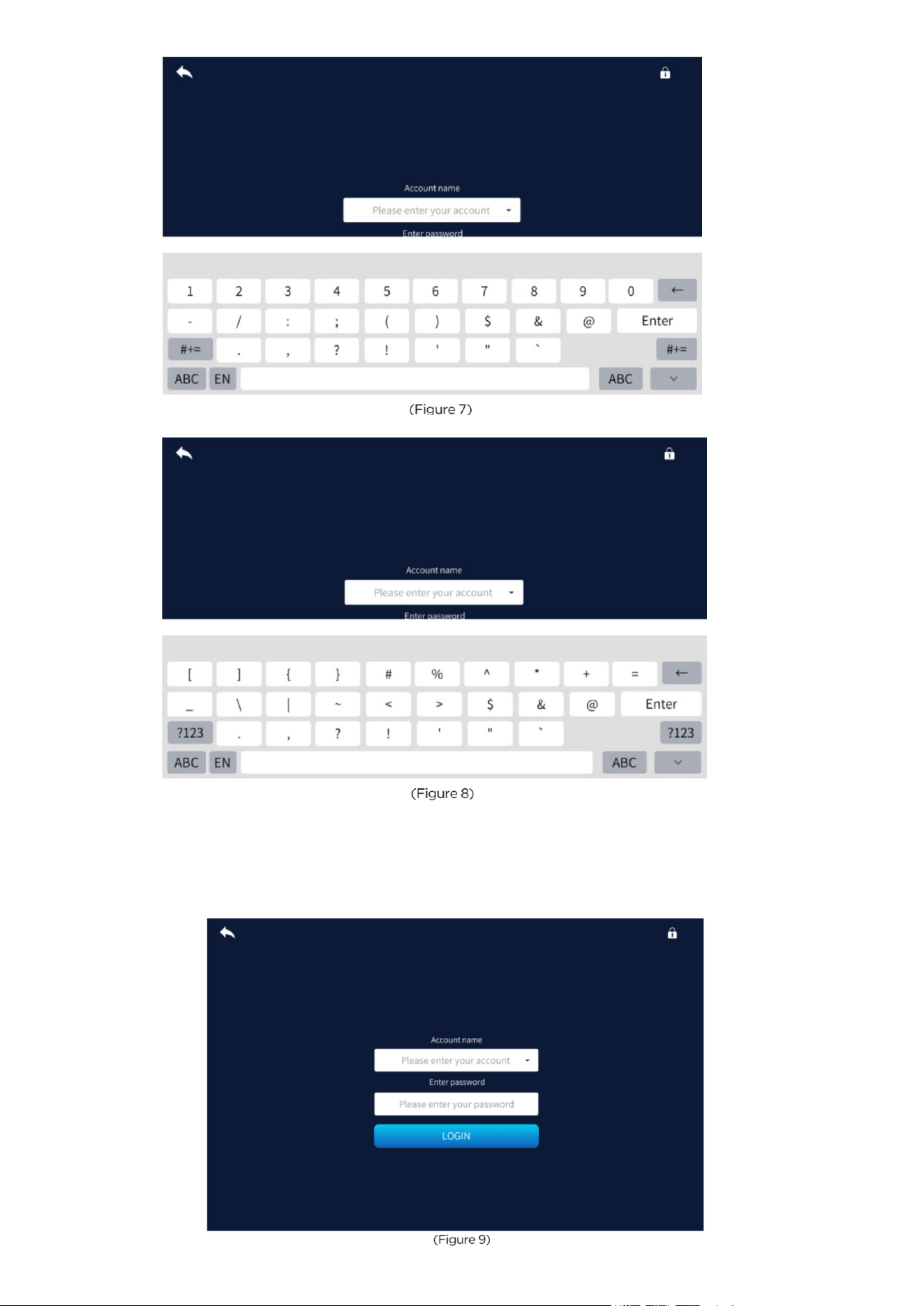
1.4 Log In
You can now log in using the account and password you created.
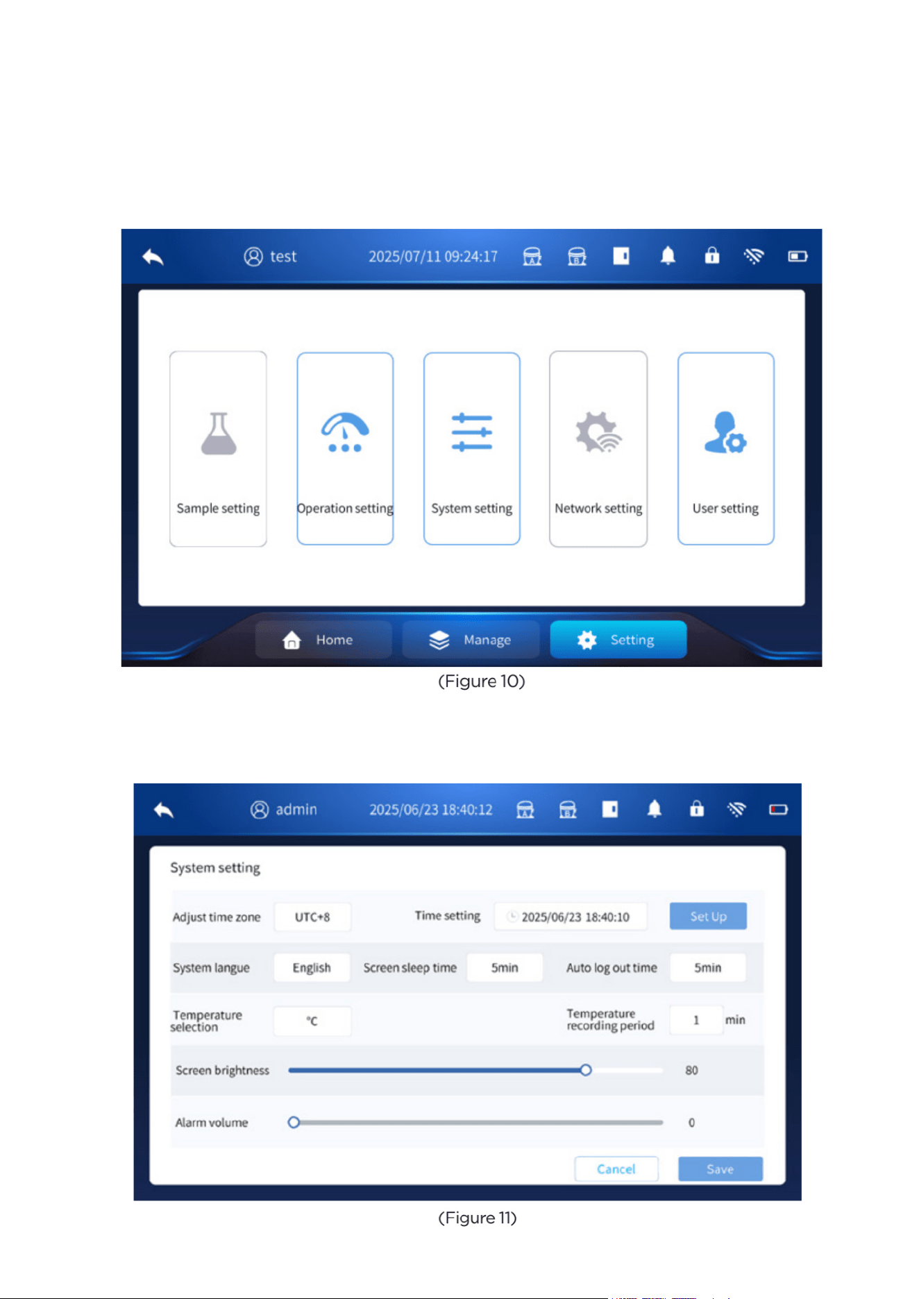
Settings
2. Settings
• Select “Settings” on the home screen to access the available configuration menus, including
Sample Settings, Operation Settings, System Settings, Network Settings, and User Settings. Op-
tions that appear in blue are active and can be adjusted, while options shown in gray indicate
functions that are not currently available for this model or configuration.
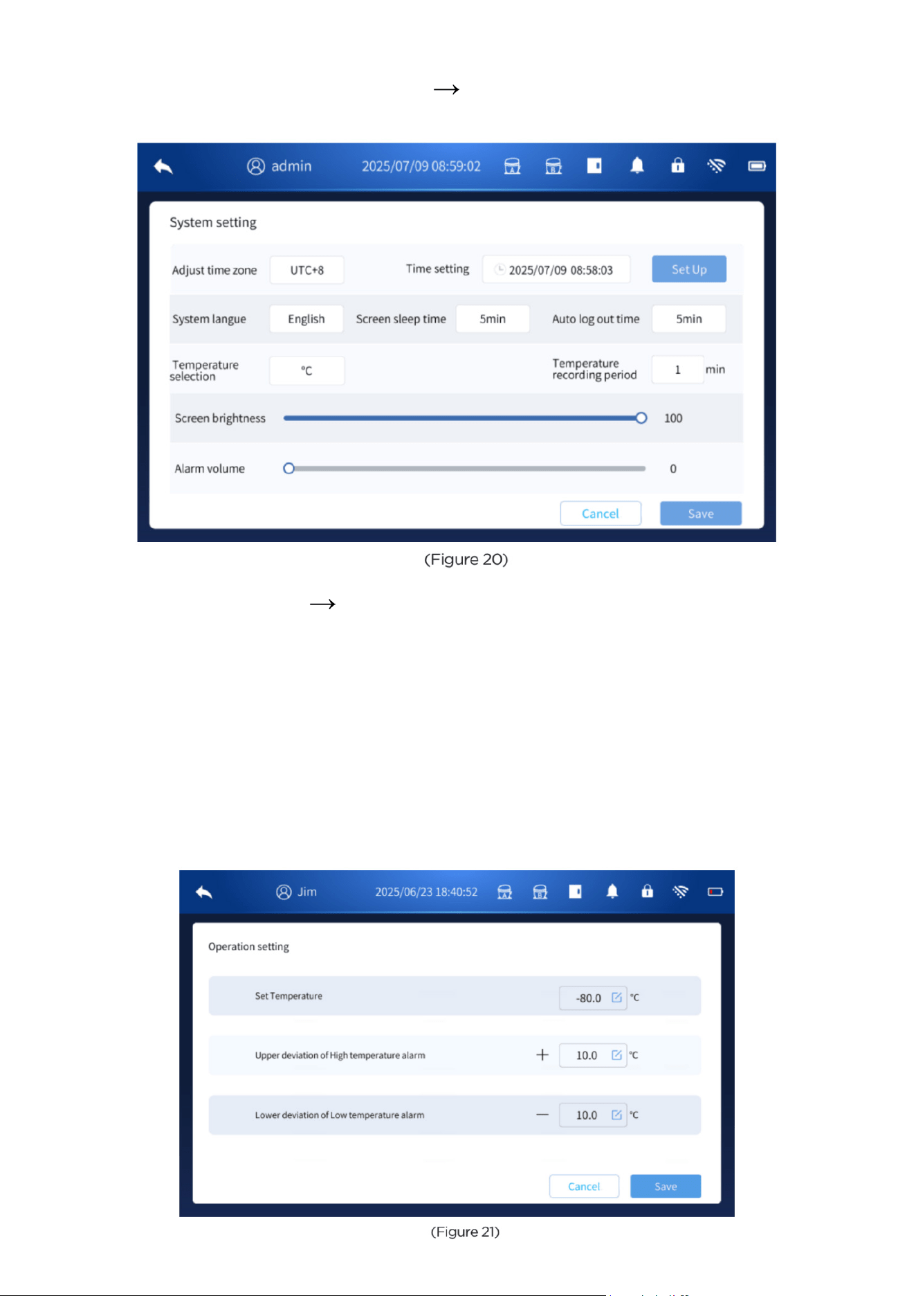
2.1 System Settings
Enter the system setting interface, as shown in Figure 11 below, and you can set the following
func tions:
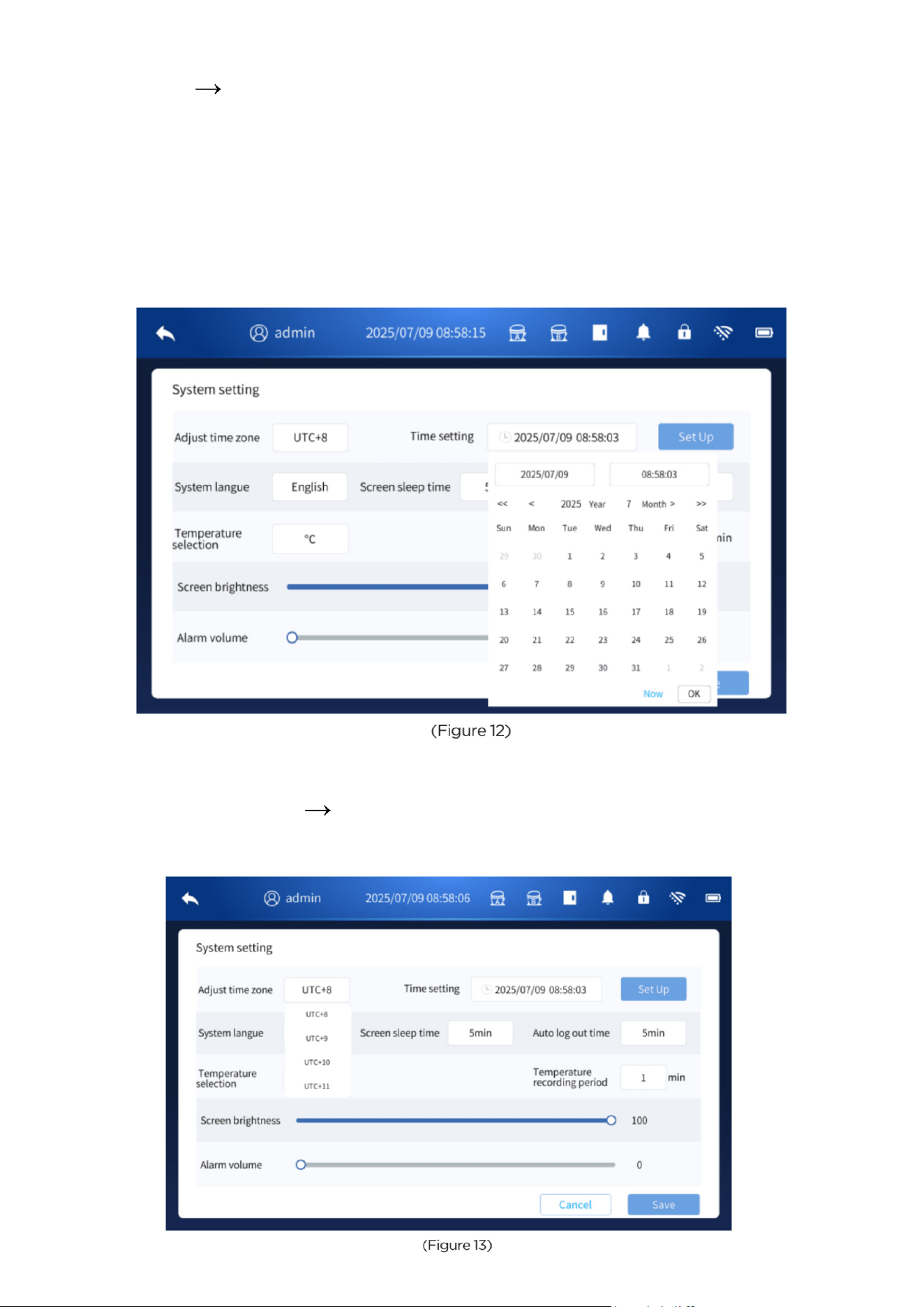
2.1.1 Time Setting
• Go to Setting System Setting, then tap Time setting pop-up.
• Enter the current local time, then tap Set Up.
• A pop-up window will ask to restart the controller. Tap Confirm Restart to apply the new time.
Example (UTC+8):
If your local time is 16:58:03, enter 08:58:03 in the time field and tap Set Up.
After a restart, the system will display the equivalent UTC time at the top.
Because UTC+8 is 8 hours ahead, the displayed time becomes:
16:58:03 = 08:58:03 + 8 hours
This is normal and indicates the time was set correctly.
2.1.2 Time Zone Setting
• The default time zone is UTC+8.
• To change it, go to Setting System Setting, then tap Adjust Time Zone.
• Select the correct time zone (UTC–12 to UTC+12) and tap Set Up.
• A pop-up will ask to restart the controller. Tap Confirm Restart to apply the change.
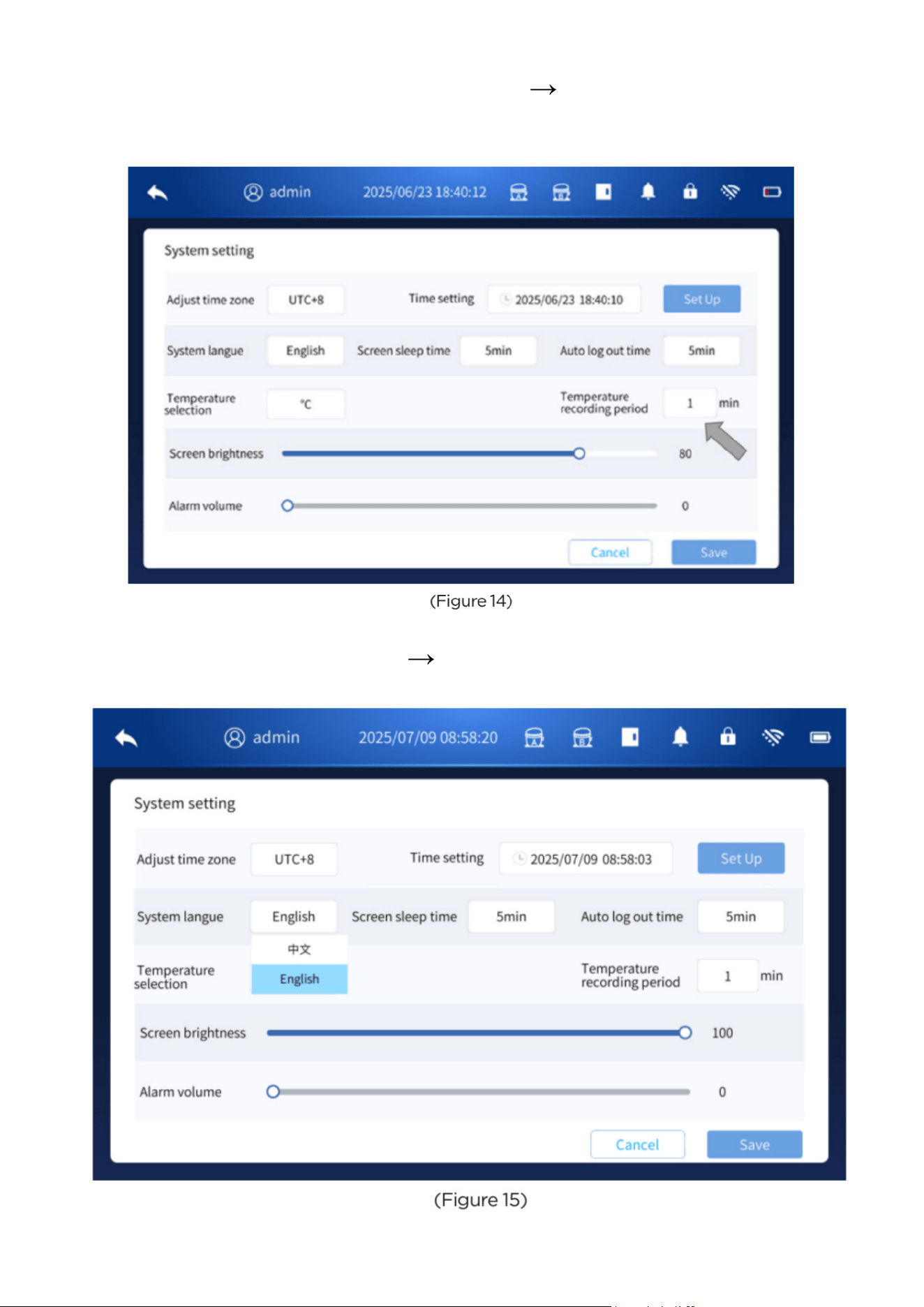
2.1.3 Temperature Recording Period Setting
• To set the temperature recording cycle, go to Settings System Setting.
• Enter the desired interval (1–240 minutes) in the temperature recording period field, then click
Save to apply the setting.
2.1.4 Language Setting
• To change the language, go to Settings System Setting.
• Select the desired language in the language menu, then click Save to apply the setting.
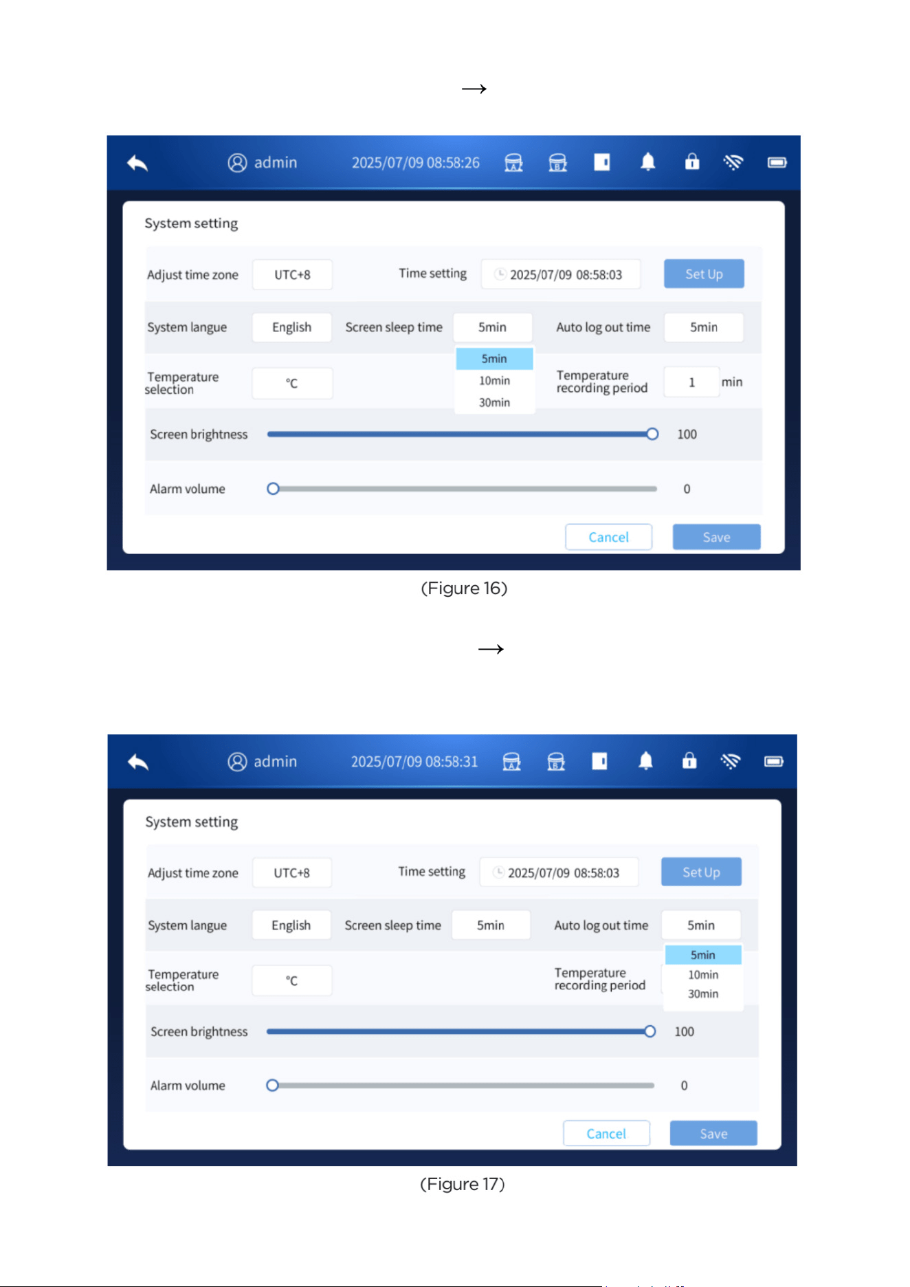
2.1.5 Screen Sleep Time Setting
• To adjust the screen sleep time, go to Settings System Setting.
• Select the desired sleep duration, then click Save to apply the setting.
2.1.6 Auto Log-Out Time Setting
• To set the automatic log-out time, go to Settings System Setting.
• Select the desired log-out interval in the auto log-out time field, then click Save to apply the
setting.
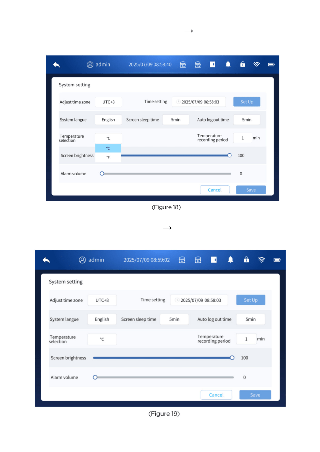
2.1.7 Temperature Unit Setting
• To change the temperature display unit, go to Settings System Setting.
• Select the desired unit (°C or °F) in the temperature unit menu, then click Save to apply the
setting.
2.1.8 Screen Brightness Setting
• To adjust the screen brightness, go to Settings System Setting.
• Use the slider to set the desired brightness level, then click Save to confirm the setting.
2.1.9 Alarm Volume Setting
• To adjust the alarm volume, go to Settings System Setting.
• Use the slider to select the desired volume level, then click Save to apply the setting.
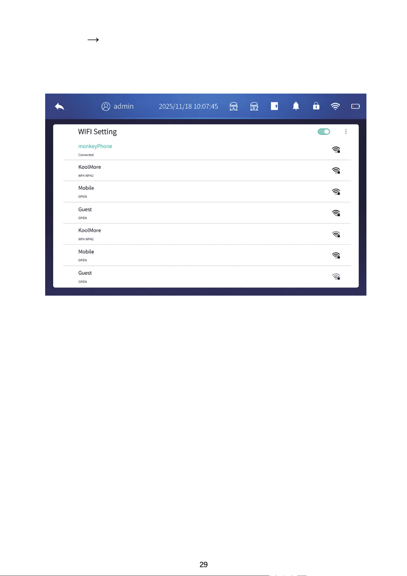
2.2 Operation Parameter Settings
After logging in, go to Settings Operation Setting. In this menu, you can adjust the following
parameters:
• Set Temperature
• Upper Deviation for High-Temperature Alarm
• Lower Deviation for Low-Temperature Alarm
After entering the desired values, click Save to apply the settings.
If the deviation values for the high- or low-temperature alarms are outside the allowable range, a
prompt will appear indicating that the values are invalid.
To disable the high- and low-temperature alarms, set the deviation value to 0°C.
Note: Both common users and administrator users are allowed to modify these settings.
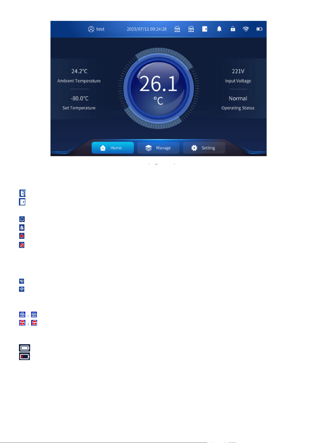
2.3 Network Settings
On the Settingss Network Settings page, tap the WIFI Setting switch icon to turn the network
on or off. When the network is turned on, select the desired Wi-Fi network from the list and enter
the correct password. After a successful connection, the Wi-Fi icon at the top of the screen will
update to show the connected status. (See attached image for an example of a successful con-
nection.)
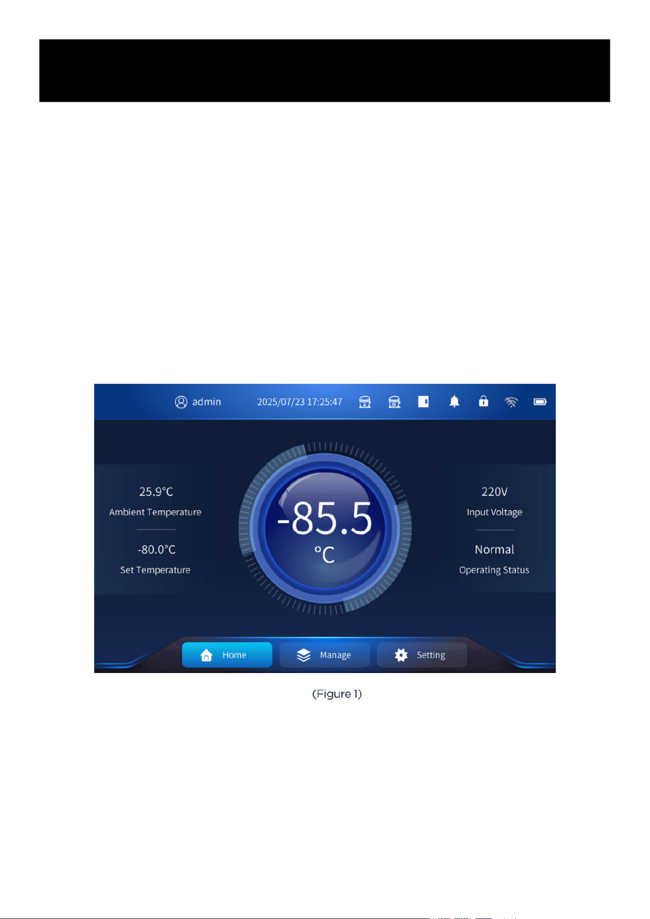
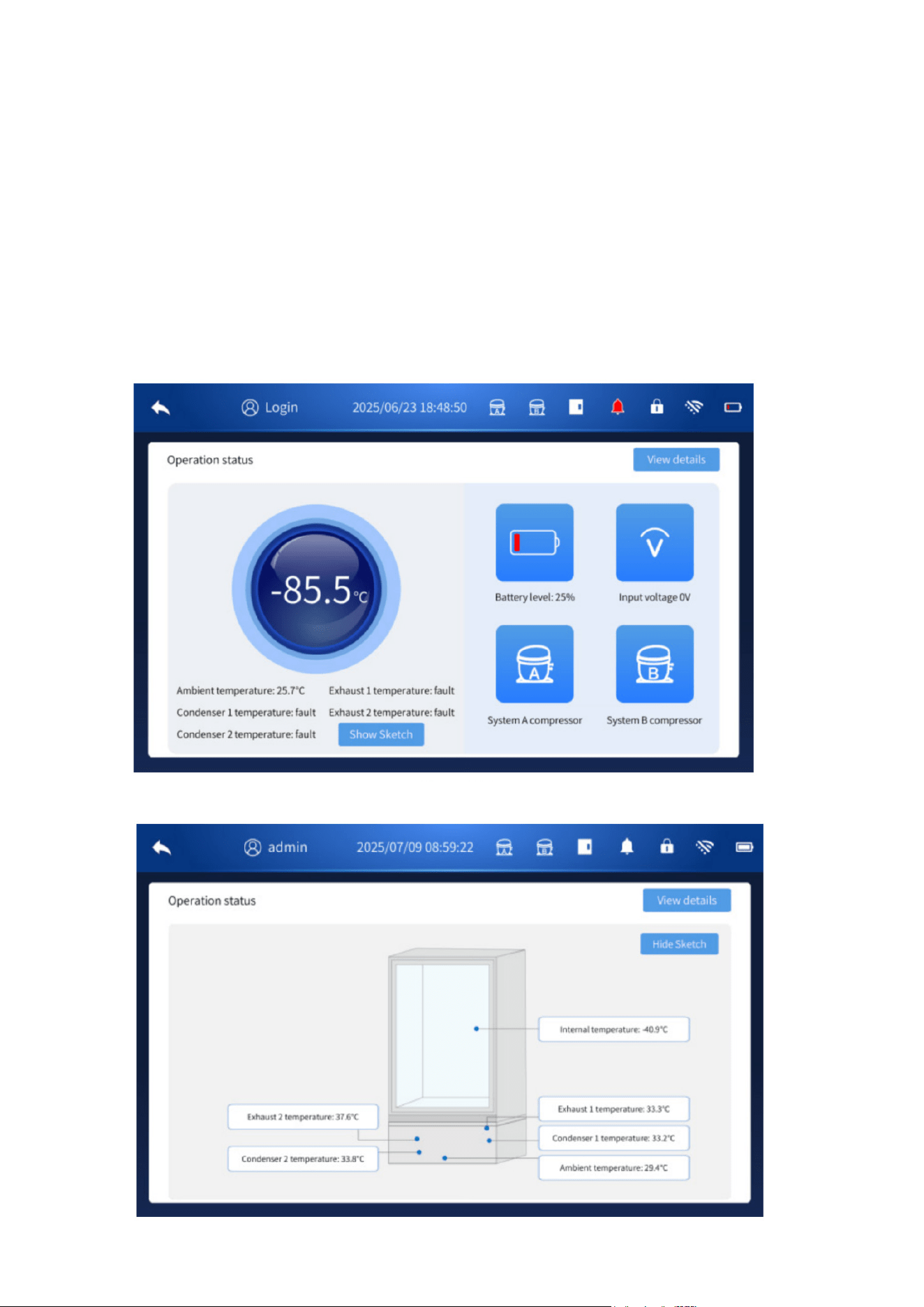
Homepage Display
3. Homepage Display
Under normal conditions, the homepage appears as shown in the figure below. The homepage
includes the following display parameters and menu options:
• Ambient Temperature – The temperature of the environment where the product is installed.
• Set Temperature – The temperature value configured by the user.
• Input Voltage – The current input voltage supplied to the unit.
• Operating Status – Indicates whether the unit is functioning normally.
• Cabinet Temperature – The real-time internal temperature of the product.
• Home – Returns to the homepage display.
• Manage – Provides access to alarm information, messages, temperature records, event re-
cords, operating status, and local device information.
• Setting – Allows configuration of system parameters, operation parameters, and user account
management.
(Figure 22)
3.1 Top Icon Display
• Door Opening and Closing Status
Indicates door open.
Indicates door closed.
• Alarm Icon Status
Indicates normal condition (no alarm).
Indicates mute mode.
Indicates an active alarm. When an alarm occurs, the buzzer will sound.
Tap the alarm icon to temporarily mute the buzzer; the icon will change to the mute symbol.
If the alarm condition is still present after 10 minutes, the buzzer will automatically unmute.
(Figure 23)
• Network Status
Indicates not connected to a network.
Indicates network connected.
• Compressor Status
Indicates normal operation of system A/B.
Indicates a compressor fault in system A/B.
• Battery Status
Indicates the battery is fully charged.
Indicates the battery is low and needs to be charged as soon as possible.
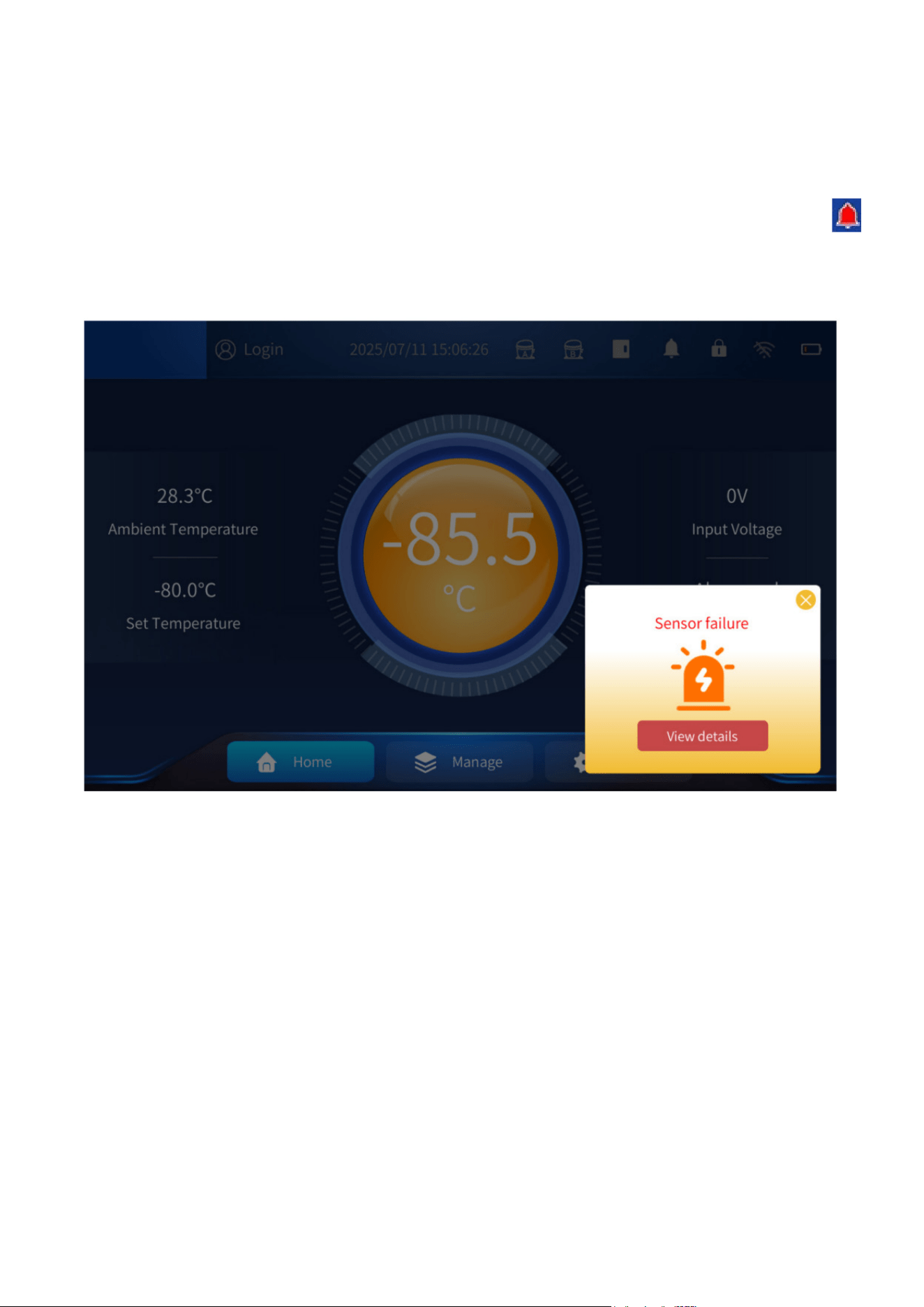
3.2 Alarm Status
3.2.1 Alarm Status
• When the freezer is operating abnormally (such as during a high-temperature alarm, low-tem-
perature alarm, door-open alarm, or system failure), the central operating status indicator turns
orange (normal status is blue). An alarm pop-up window will appear, and the buzzer will sound.
• When an alarm occurs, you may close the alarm pop-up window or tap the Alarm Bell icon
to temporarily mute the alarm sound.
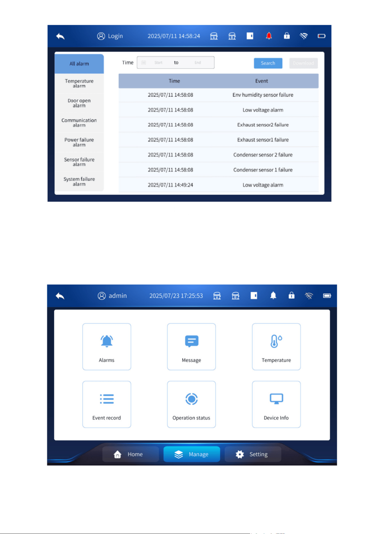
3.2.2 Alarm view
Click View Details in the alarm window to see additional alarm information, or click the X in the
upper-right corner to close the pop-up window. If the alarm condition still exists after 10 minutes,
the alarm window will reappear and the buzzer will sound again.
You can also manually check alarm records by going to Manage - Alarms - All Alarm.
While logged in, select a Start and End time, then click Search to display alarm information for that
time period.
To export the alarm records, insert a USB flash drive and click Download to save the data to the
USB.
Note: Both common users and administrator users can adjust this setting.
(Figure 24)
Management Page
4. Management Page
• Click the Manage icon at the bottom of the screen to open the management page. From this
menu, you can view alarm information, system messages, temperature records, event records,
operating status, and device information.
(Figure 25)
(Figure 26)
4.1 Alarm Information
See the description in Section 3.2.2.
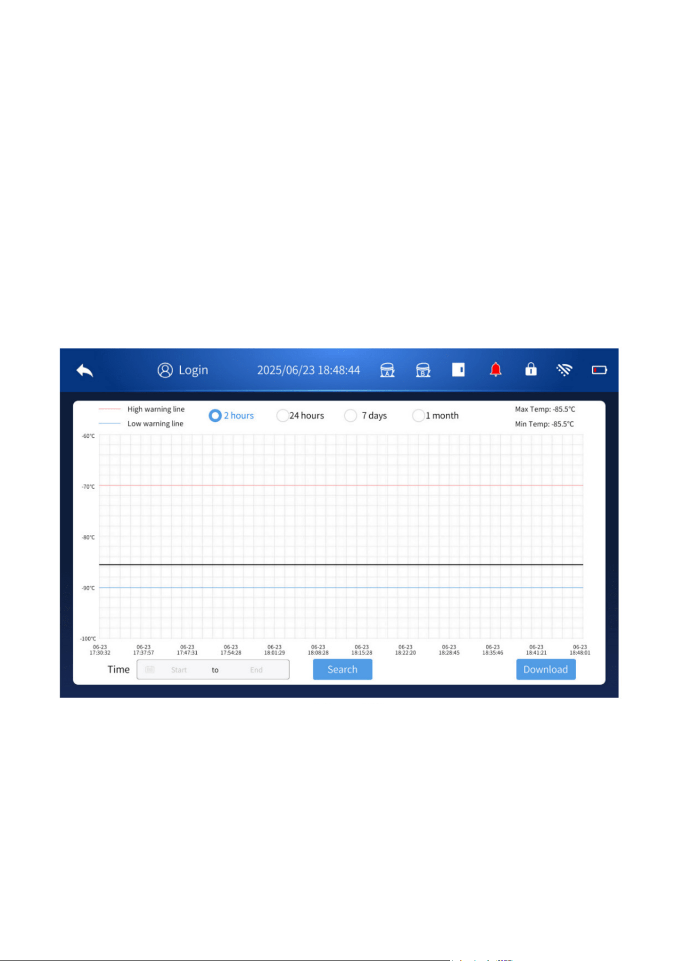
4.2 Temperature
• Temperature Page Functions: The temperature page displays the high-temperature alarm up-
per limit, low-temperature alarm lower limit, maximum temperature, and minimum temperature.
• The maximum and minimum values shown in the upper-right corner represent the highest and
lowest temperatures recorded by the cabinet sensor during each temperature-recording inter-
val for the selected time period.
• Exporting Temperature Data (Quick Select): While logged in, insert a USB flash drive.
• Select a time period—2 hours, 24 hours, 7 days, or 1 month—and then click Download to export
the temperature data for that period to the USB drive.
• Exporting Temperature Data (Custom Range): You may also choose a custom time range by
selecting Start – End, then clicking Search.
• You can then download the corresponding data (in PDF table format) to the USB flash drive.
• Note: The custom time range cannot exceed 1 month.
4.3 Message System
Different users can leave messages for other users of the machine by logging in with their own ac-
counts. The recipient will receive the message the next time they log in. The process is described
below:
4.3.1 Create a New Message:
While logged in, click New (+), select the recipient, and enter your message.
After sending, you can check the Outbox to confirm the message status.
(Figure 27)
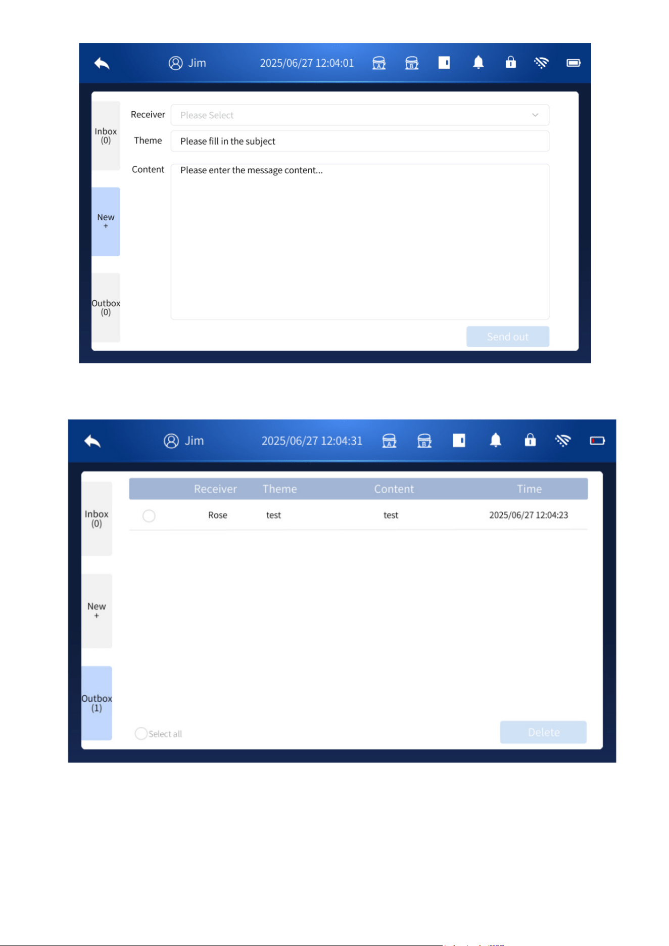
4.3.2 Inbox: When the account is logged in, click the inbox to view the message details.
(Figure 28)
(Figure 29)
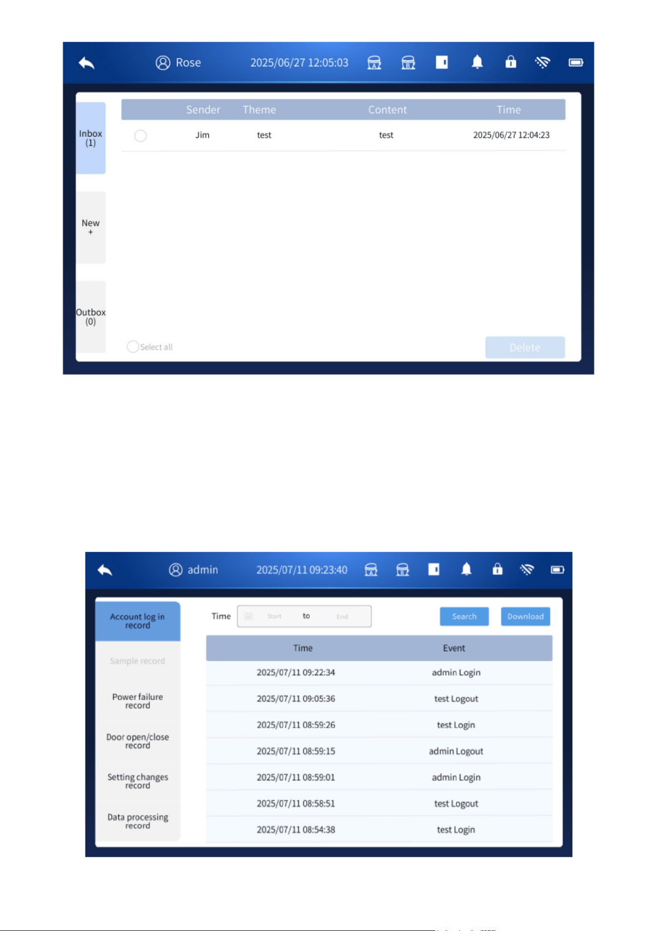
4.4 Event Log
• The event record page allows you to view detailed information such as account logins, power
outage records, door opening and closing events, and data export records for setting changes.
• While logged in, select a Start and End time, then click Search to display events within that time
period.
• To export the event records, insert a USB flash drive and click Download to save the data to the
USB.
(Figure 30)
(Figure 31)
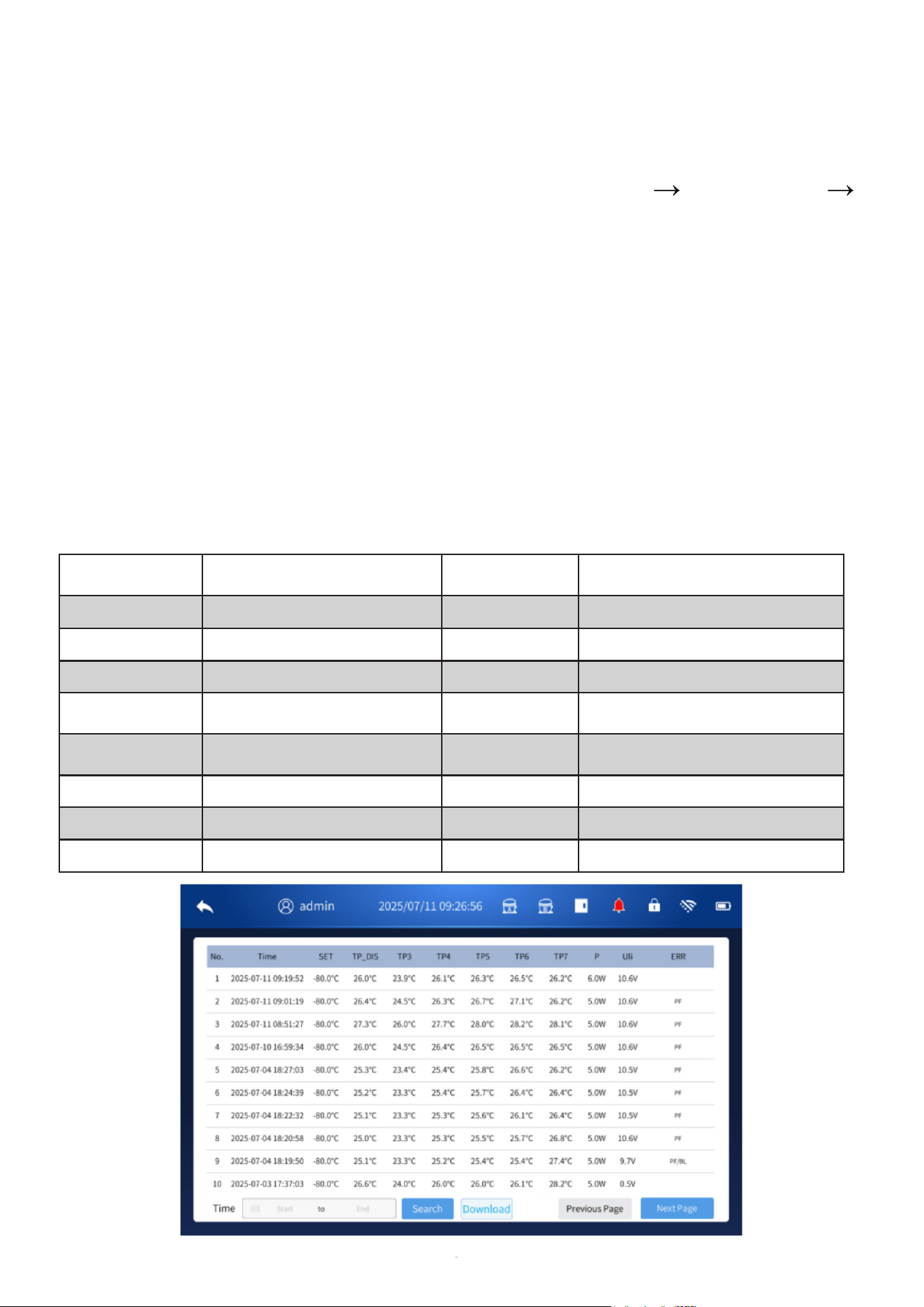
4.5 Operation Status
4.5.1 While logged in, click View Details to check sensor readings, including the internal tempera-
ture, system A exhaust temperature, system B exhaust temperature, system A condenser tempera-
ture, and system B condenser temperature. Selecting View Details displays the temperature moni-
toring values for each corresponding sensor.
The recording interval for these values can be configured under Settings System Setting
Temperature Recording Period.
The sensor and system indicators are defined as follows:
• SET — Set temperature
• TP_DIS — Displayed temperature
• TP3 — Ambient temperature
• TP4 — Condenser 1 temperature
• TP5 — Condenser 2 temperature
• TP6 — Exhaust 1 temperature
• TP7 — Exhaust 2 temperature
• P — Total power of the unit
• Uli — Lithium battery voltage
• ERR — Fault alarm code
The detailed meanings of these values are shown below.
Fault Alarm
Codes
Fault/Alarm Name
Fault Alarm
Codes
Fault/Alarm Name
H1 High temperature alarm EP Power supply overvoltage alarm
L1 Low temperature alarm BL Low battery alarm
H2 High ambient temperature alarm EVL Alarm for low voltage
H3
Alarm for high condenser 1
temperature
EVH Alarm for high voltage
H4
Condenser 2 high temperature
alarm
ESA System A compressor fault alarm
E1-E8 Sensor fault alarm ESB System B compressor fault alarm
do Door open alarm PF Power failure alarm
Eb Battery overvoltage alarm EE Communication abnormality alarm
(Figure 32)
2. During operation, there are two states: dual compressor and single compressor running alter-
nately. When the compressor is running, the exhaust temperature will rise. By checking whether
the exhaust temperature values of system A and system B are much higher than the ambient tem-
perature, it can be judged whether the compressor is in operation.
3. When the temperature is abnormal, a high temperature alarm will occur: when the ambient tem-
perature exceeds the default value, an ambient temperature high temperature alarm will be issued;
when the condenser sensor temperature exceeds the default value, a condenser high temperature
alarm will be issued.
4. In the logged-in state, you can click the “View details” button to view system operation infor-
mation (set temperature, various sensor values, etc.), and select the corresponding time period to
query and download relevant content.
(Figure 33)
(Figure 34)
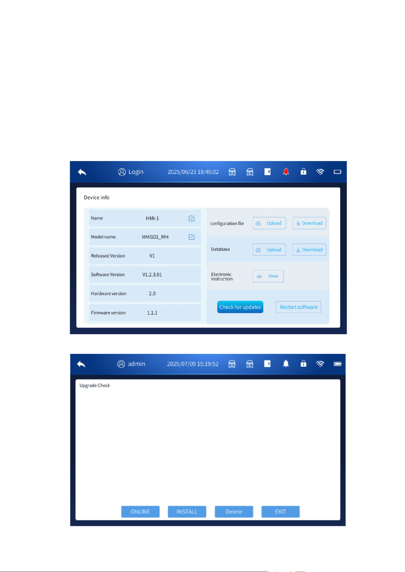
4.6 Device Information
• In the logged-in state, click Restart Software to restart the system.
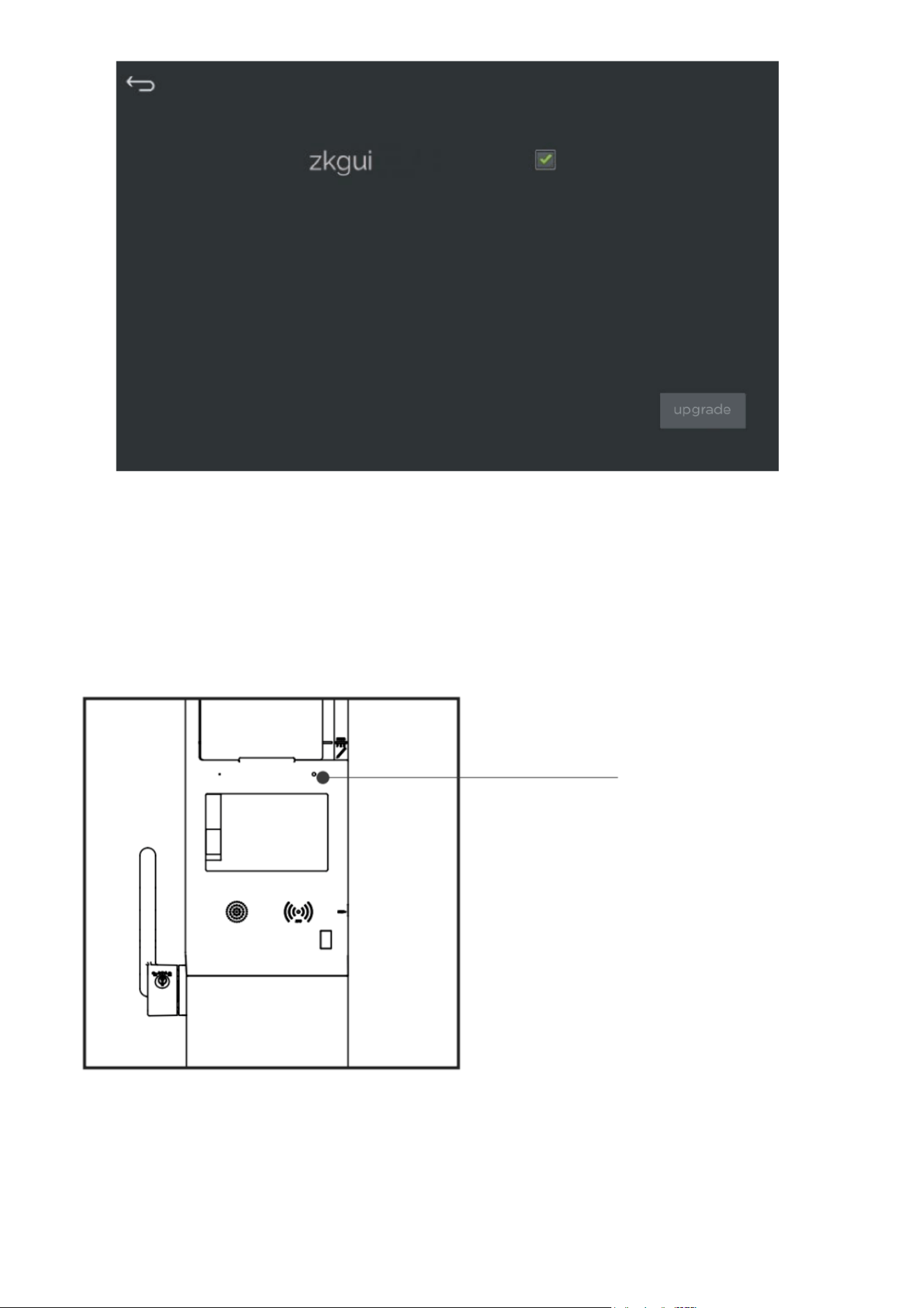
• To update the system software, click Check for Updates, insert a USB flash drive, select the
upgrade file, and click Upgrade to begin the update.
Notes:
A valid upgrade file is required, and software updates are normally not needed for everyday use.
Updates are intended primarily for trained technicians.
The USB flash drive must be formatted to FAT32, have a capacity of 32GB or less, and contain no
partitions.
For best compatibility, use well-known brands such as SanDisk, Kingston, Samsung, etc.
(Figure 35)
(Figure 36)
5. Other
5.1 State Indicator
The panel indicator shows the current operating status of the freezer:
• Green light: The refrigerator is operating normally after power-on.
• Red light: A fault has occurred.
State Indicator
(Figure 37)
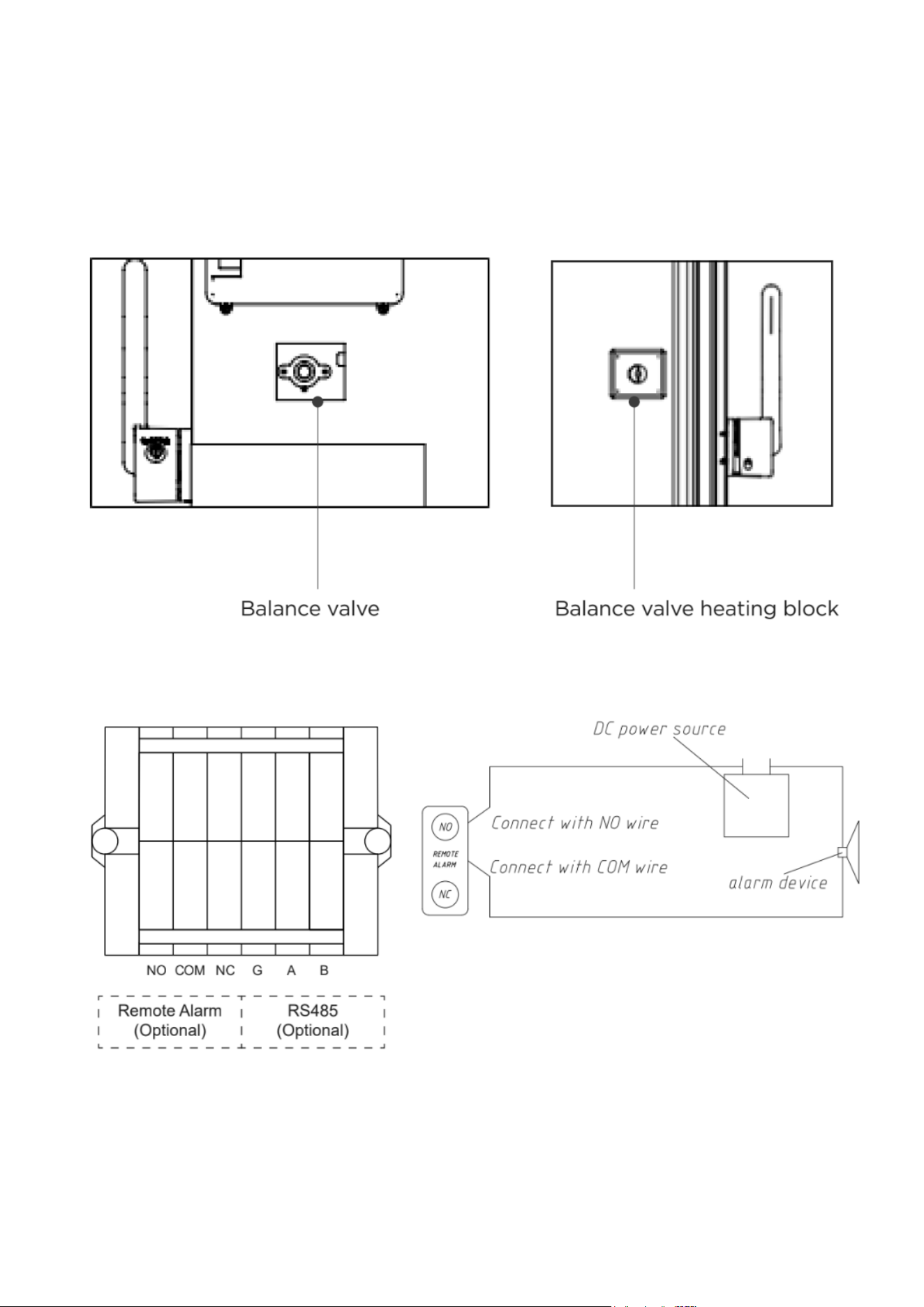
5.2 Balance Valve
When the interior of the biomedical freezer is at a very low temperature, a pressure difference can
form between the inside and outside of the unit. This may make the door difficult to open.
To release this pressure, the balance valve automatically opens to allow ventilation and equalize
the internal and external pressure, helping the door open more easily.
A small heating block is located behind the balance valve. This heater activates to prevent frost
buildup around the valve opening. It is normal for the balance valve area to become warm during
operation.
Remote Alarm Function
This product includes a remote alarm output function. When an alarm occurs, the freezer can send
an alarm signal through the remote alarm connector.
Connector Details
• Located in the lower-left area at the back of the unit.
• Maximum load capacity: DC 30V / 2A.
• Provides NO (Normally Open), COM (Common), and NC (Normally Closed) contacts.
• For optimal performance, the remote alarm cable should not exceed 9 feet in length.
Notes:
1. Users must install their own external alarm device and connect it to the remote alarm interface.
2. Pressing Mute on the display panel silences the audible alarm only; the remote alarm output
remains active.
3. Any alarm condition will trigger the remote alarm output.
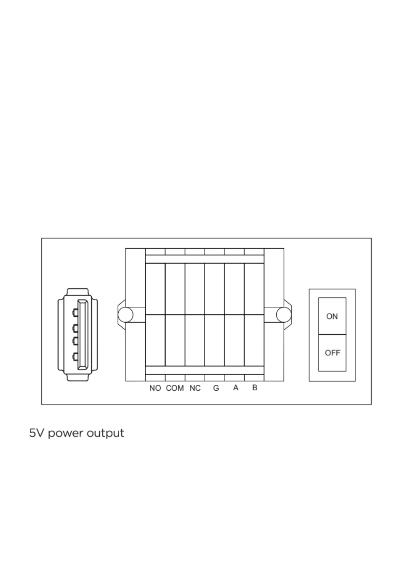
Remote Communication Function (RS-485)
This freezer can be equipped with an optional RS-485 remote communication interface. Through
the RS-485 port, the freezer can transmit temperature data, alarm information, and other system
signals to external monitoring software.
• The RS-485 connector is located behind the lower rear cover of the product.
• The connector includes RS485_A, RS485_B, and GND.
• RS485_A and RS485_B form a differential pair and should be wired using twisted-pair cable.
5V Power Output Function
The freezer includes an optional 5V power output for external devices.
• The 5V output port is a USB socket located at the lower-left area at the back of the unit.
• Output capacity: 5V / 0.5A.
• Do not exceed this output capacity when connecting external devices, as doing so may dam-
age the control board.
Notes:
Due to product improvements or specific contract requirements, the actual functional configura-
tion of your unit may differ slightly from what is described here. Always refer to the features of the
physical product you received.

WARNING
When the interior of the biomedical freezer is at a low temperature, a pressure difference may
form between the inside and outside of the unit, making the door difficult to open. The balance
valve opens automatically to equalize pressure and allow easier door opening.
A small heater around the balance valve activates to prevent frost buildup, so it is normal for this
area to become warm during operation.
CAUTION
• Do not splash water directly onto the freezer body. Moisture may reduce electrical insulation or
cause metal parts to rust.
• Do not splash water directly onto the freezer body. Moisture may reduce electrical insulation or
cause metal parts to rust.
• Do not place heavy objects on top of the unit, as this may cause deformation.
Clean This Product
• Wipe off light dust using a dry cloth.
• For internal cleaning, use a cloth soaked in mild neutral detergent. Remove detergent with a
damp cloth and finish with a dry cloth.
• Do not pour water into the housing or chamber—water may damage electrical insulation and
cause faults.
• The compressor and other mechanical parts are sealed and do not require lubrication.
• Clean the freezer once a month to maintain appearance and performance.
• Regular cleaning helps prevent frost buildup and keeps the condenser filter screen clear.
Cleaning the Condenser Filter Screen
1. Remove the front bottom hood and access the filter screen.
2. Wash the filter screen with clean water.
3. Clean any dust or debris on the condenser.
4. After the filter is completely dry, reinstall it and reattach the hood.
5. Clean the filter screen monthly under regular use.
Note: A blocked filter screen reduces cooling efficiency and may shorten the service life of the
freezer.
Defrosting Inside the Biomedical Freezer
Excessive frost can impair cooling performance. Defrosting is recommended monthly, or at least
every three months.
Defrosting Steps
• Remove stored items and place them in a suitable storage environment.
• Unplug the freezer or turn off the miniature circuit breaker.
• Open both the inner and outer doors to allow natural defrosting to occur.
• Wipe accumulated water from the bottom of the freezer with a dry cloth.
• After defrosting and cleaning, close the doors and restart the freezer.
Maintenance

• Once the unit has fully cooled, return the items to the freezer.
CAUTION
Do not use knives, screwdrivers, or any sharp tools to remove frost.
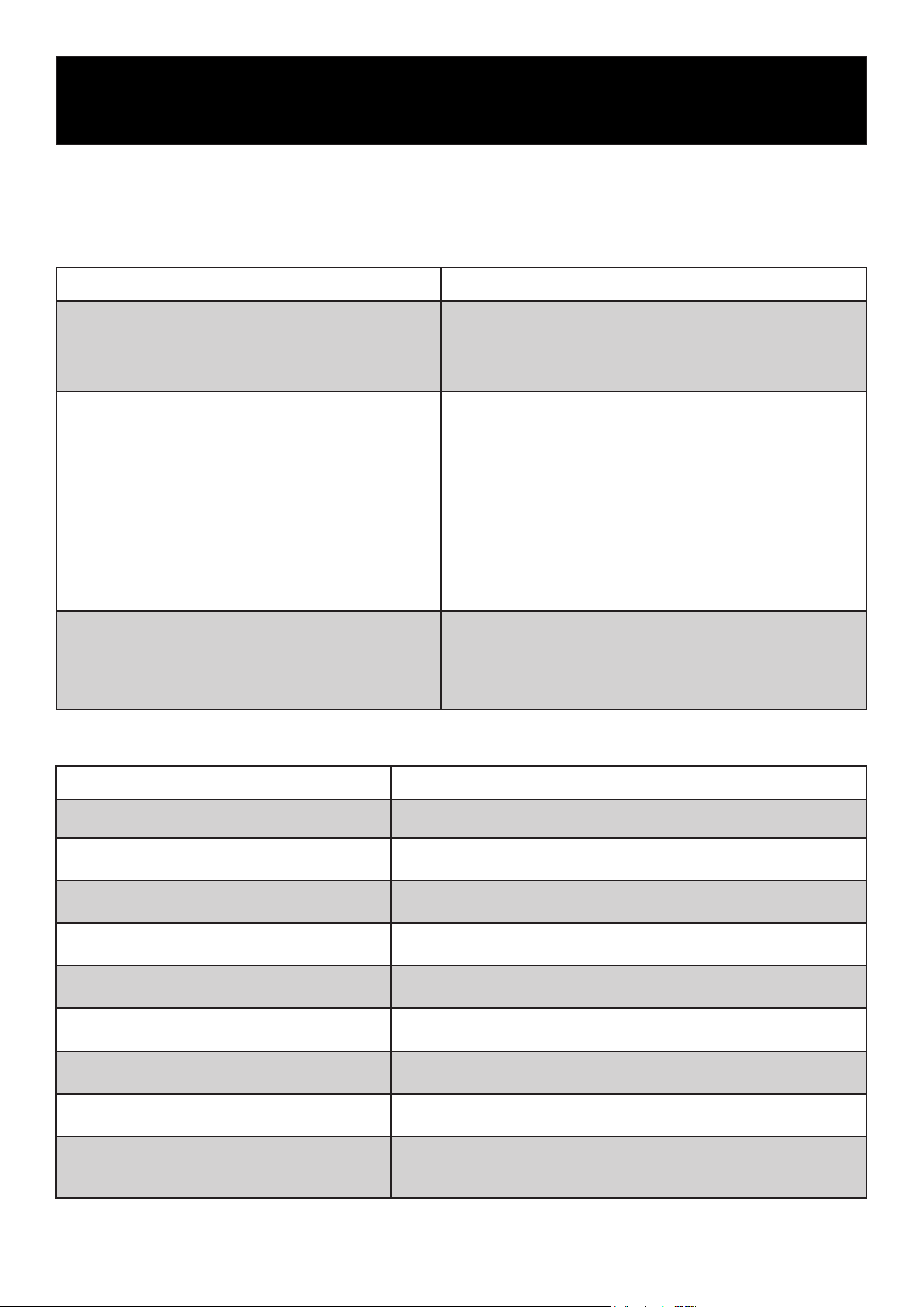
Replacement Cycle of Components
Part / Component Suggested Replacement Cycle
Condenser fan (12V, 3.5W) 5 years
Equipment Out of Service
Out of Service:
If the freezer will not be used for an extended period:
• Disconnect the power supply.
• Clean the inside and outside surfaces with a soft, damp cloth and allow to dry completely.
• Close and seal the doors.
• Lock the unit to prevent children from entering the chamber and risking suffocation.
Scrap / Disposal
When the freezer reaches the end of its service life:
• Dispose of the unit through qualified professional recycling organizations in accordance with
local regulations.
• Do not disassemble the unit yourself. Unauthorized dismantling is prohibited.
• Place scrapped equipment in a secure location away from children to avoid hazards.
Name Low-temperature Freezer
Model
Electrical Shock Protection
Class
Class I
Power Supply 100V-240V~/50/60Hz
Compartment Temperature -40°C~-86°C
Refrigerant Mixed Refrigerant
Cooling Mode Direct Cooling
Volume (cu. ft.)
Rated Current
Operating Power
Weight
Product Dimensions
(W * D * H)
Noise (sound pressure level)
Shelf Weight Capacity
Specification
KM-PHF-30CUL KM-PHF-25CUL KM-PHF-20CUL
30
25 20
7.0A (at 240V)
14.0A (at 100V)
6.5A (at 240V)
14.0A (at 100V)
6.5A (at 240V)
14.0A (at 100V)
495W (at 240V)
850W (at 100V)
450W (at 240V)
720W (at 100V)
360W (at 240V)
550W (at 100V)
758 lbs 705 lbs 635 lbs
46.26 × 39.17 × 77.95
in
40.55 × 39.17 × 77.95
in
34.84 × 39.17 × 77.95
in
46 dB 46 dB 46 dB
192 lbs
165 lbs 108 lbs
Description of Technical Parameters
The technical parameters in this table are measured under standard conditions. Specifications
may change without prior notice due to product improvements or technical updates. The actual
parameters for your unit are those shown on the nameplate attached to the unit.

Packing List
Name
Instructions for
Use
Key (for Lock)
Defrosting
Shovel
Spacer Bracket Shelf Shelf Clip
Quantity 1 copy 2 pcs. 1 pc. 2 pcs. 3 pcs. 15 pcs.
Note: Optional accessories, such as an external padlock or handle, may vary depending on the
actual product configuration.
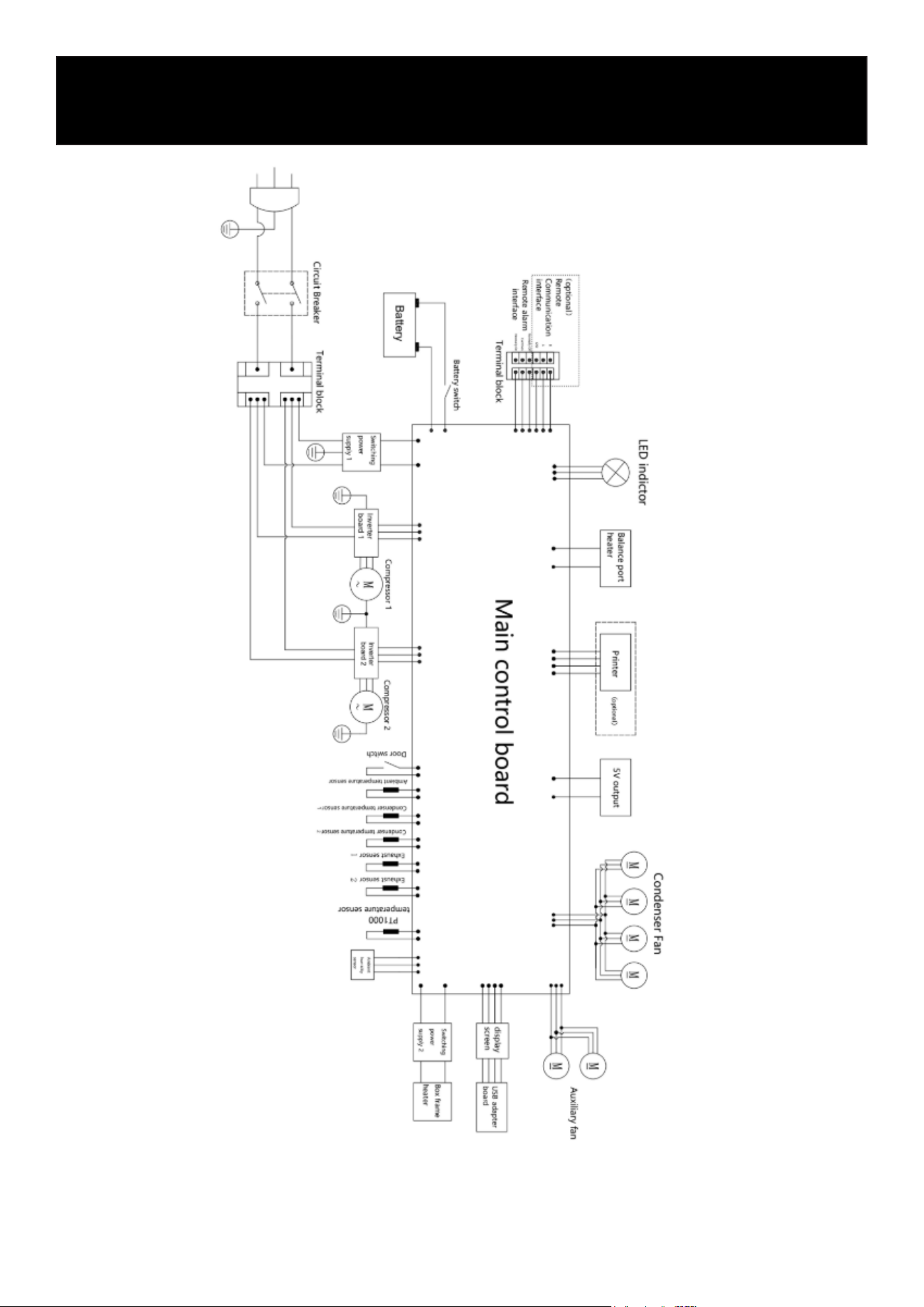
Electrical Schematic Diagram
Note: Some models do not include a running capacitor or condenser fan. Please refer to the actual
product.

Protection of the Environment
This symbol attached to the product means that it is an appliance whose disposal is subject to
the directive on waste from electrical and electronic equipment (WEEE). This appliance may not in
any way be treated as household waste and must be subject to a specific type of removal for this
type of waste. Recycling and recovery systems are available in your area (waste removal) and by
distributors. By taking your appliance at its end of life to a recycling facility, you will contribute to
environmental conservation and prevent any harm to your health.
Troubleshooting
Any product may experience a fault during use. Please monitor the equipment regularly, and if you
notice any abnormal operation, refer to the troubleshooting table below for guidance. If the issue
cannot be resolved, contact our Customer Service Center promptly.
General Faults
Fault Troubleshooting
The product does not work.
• Check whether the power circuit breaker is on.
• Ensure the power voltage is not too low.
• Verify the power switch is turned on.
• Check whether the fuse is blown.
Poor cooling
• Check whether the ambient temperature is too high.
• Ensure both inner and outer doors are tightly closed.
• Verify that the air inlet is clean and unobstructed.
• Inspect the condenser and filter screen for dirt or block-
age.
• Make sure the temperature is set correctly.
• Confirm the product is not exposed to direct sunlight.
• Ensure the unit is kept away from heat sources.
• Check whether the rubber hole cover and insulation
around the test-through testing holes are correctly
installed.
Excessive noise
• Ensure the product is installed on a solid, level surface.
• Check whether any external items are touching the
housing.
• Confirm that the unit’s adjustable feet are properly
leveled.
Fault Troubleshooting
Door open alarm Verify that the door is fully closed.
Power failure alarm
Check whether the power cord is unplugged or if the miniature
circuit breaker is disconnected.
High ambient temperature alarm Check whether the indoor temperature is too high.
High ambient temperature Check whether the exhaust sensor is disconnected.
Exhaust sensor fault alarm Check the battery voltage and ensure the system is powered on.
Condensation sensor fault alarm Check whether the condensation sensor is disconnected.
Abnormal input voltage alarm Check whether the input voltage is excessively high or low.
System A/B compressor fault alarm Check for issues with the corresponding refrigeration system.
Communication fault alarm
Confirm that the communication cable is inserted correctly and
verify whether the main control board, display, or communication
board is damaged.
Alarm Faults

LIMITED WARRANTY
KoolMore Supply Inc. extends a limited warranty to the original purchaser, guaranteeing that this KoolMore product is
free from manufacturing defects in material or workmanship for one year from the date of purchase.
Should you discover any such defect within the warranty period, KoolMore Supply Inc. reserves the right to repair or re-
place the product without charge, or to cover the cost of replacement parts and repair labor needed to correct defects
present at the time of purchase or resulting from regular usage, when the appliance has been installed, operated, and
maintained as per the instructions provided.
At its sole discretion, KoolMore Supply Inc. may decide to replace the product. In such an event, your replacement
appliance will carry the warranty for the remaining term of the original unit’s warranty period.
This warranty is valid exclusively to the original purchaser of the product and only applicable within the United States.
The warranty commences from the date of original consumer purchase. Proof of the original purchase date will be
required to obtain service under this warranty.
Under this limited warranty, your sole and exclusive remedy will be product repair, as outlined above. All services must
be provided by a KoolMore designated service company.
To claim warranty or request repair service:
Email [email protected]. Please include your name, address, phone number, warranty repair request, and a copy
of your proof of purchase receipt. Alternatively, visit koolmore.com and use the Contact Us page. A KoolMore custom-
er service representative will promptly arrange service for your appliance.
We thank you for choosing KoolMore.
WARRANTY EXCLUSIONS
This limited warranty will not cover:
1. Failure of the product to perform during power failures or interruptions,
or due to inadequate electrical service.
2. Damage incurred during transportation or handling.
3. Damage caused by accidents, vermin, lightning, winds, fire, floods, or acts of God.
4. Damage resulting from accidents, alterations, misuse, abuse, improper installation, repair, or maintenance. This
includes using any external device that alters or converts the voltage or frequency of electricity.
5. Unauthorized product modifications, repairs by unauthorized centers, or use of non-approved replacement parts.
6. Abnormal cleaning and maintenance not aligned with the user’s manual.
7. Use of incompatible accessories or components.
8. Any costs associated with repairs or replacements under these excluded circumstances shall be the responsibility
of the consumer.
WARRANTY