
POWERPIPE X SERIES
PPX8 | PPX8-M | PPX10 | PPX10-M | PPX12 | PPX12-M | PPX15 | PPX15-M
INSTALLATION MANUAL
2
POWERPIPE X SERIES SUBWOOFER
PPX8 | PPX10 | PPX12 | PPX15
PPX8-M | PPX10-M | PPX12-M | PPX15-M
TABLE OF CONTENTS
2 Box Contents
2 Introduction
2 Important Safety Information
2 Preparation
3 Required Parts by Application
3 CEILING INSTALLATION
3 Subwoofer Enclosure Placement
3 Attic or Above Joists Placement
4 Joists Placement
4 Attaching the PPX Pipe Tube
6 Ceiling Prep for XPC Grille Connector
6 TRUFIG Mounting: Drywall Flush
6 TRUFIG Mounting: Solid Surface
7 WALL INSTALLATION
9 CABINET INSTALLATION
11 Accessories
12 Technical Specifications
16 Warranty
BOX CONTENTS
(1) PowerPipe X Series Subwoofer Cabinet
(1) PowerPipe X Series Pipe Tube
(2) PVC Port Covers
(2) Clamp Rings (Attached)
(1) Quickstart Guide
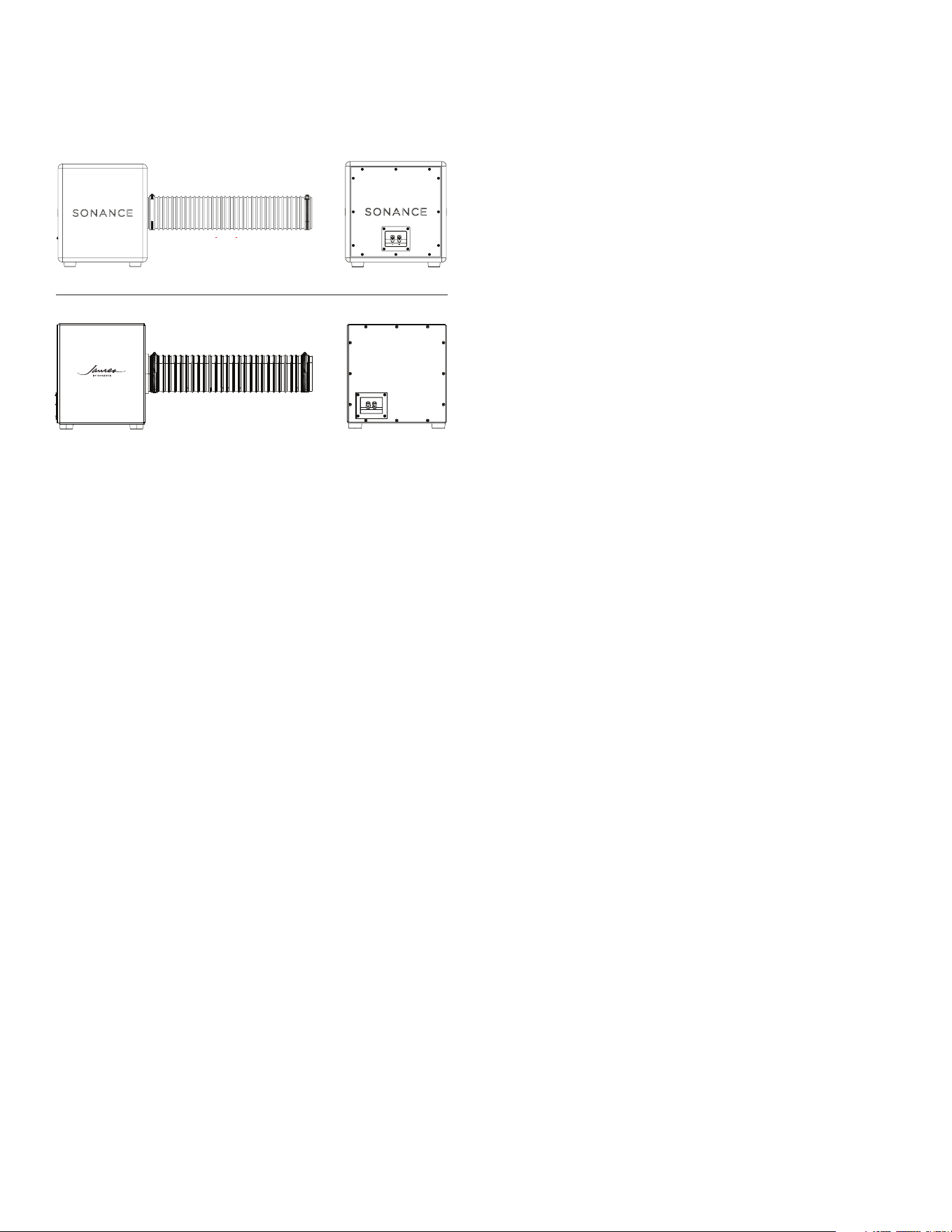
BACK VIEWSIDE VIEW
APPLICATIONS
• Ceiling Micro Trim Grille
• Ceiling Trimless Grille
• Ceiling Flush Mounted Trimless Grille
• Cabinet Toekick Grille
• Wall Toekick Grille
• Marine | Outdoor (James Marine Grade Models Only)
INTRODUCTION
The Sonance and James PowerPipe X Series subwoofers
provide premium bass performance for residential,
professional, and marine audio experiences. These
subwoofers can be installed into ceiling cavities, within
cabinets, and behind walls or closets while porting
into the applicable room to provide full, impactful
low frequencies to support music and entertainment.
PowerPipe X Series subwoofers are to be installed by an
architectural audio professional and require additional
hardware, including amplification and speakers to
complete the audio system. Contact an authorized
Sonance representative to inquire or to purchase.
IMPORTANT: Read this section in its entirety before
attempting use of the speaker.
IMPORTANT SAFETY INSTRUCTIONS
Always follow these basic safety precautions when
using your subwoofer to reduce the risk of fire, electric
shock, and injury to people or objects.
1. Read all the safety and operating instructions
before operating the subwoofer and retain them for
future reference.
2. Adhere to all warnings and precautions listed on the
subwoofer and in the operating instructions.
3. Follow all operating instructions.
4. Do not block any ventilation openings. Install in
accordance with the manufacturer’s instructions.
5. Do not install near a heat source such as radiators,
heat registers, stoves, fireplaces, or other apparatus
(including amplifiers) that produce heat.
6. Only use attachments/accessories specified by
Sonance.
7. Models with “-M” and the James by Sonance logo
are outdoor rated, suitable for installation in outdoor
environments. Sonance models without the “-M” in
its naming are NOT rated for outdoor installations.
8. Refer all servicing to qualified service personnel.
PREPARATION
Determine the required parts for your application.
IMPORTANT: The Sonance PPX subwoofer can be
installed behind the ceiling surface during pre-
construction framing, or as a renovation or remodel
installation. Some installations will require drywall
installation, patching, mudding, and/or final finish to
the surface.
BACK VIEWSIDE VIEW
SONANCE MODEL
JAMES MODEL
3
APPLICATION PPX8 | PPX10 (4” Pipe) PPX12 | PPX15 (6” Pipe)
IN-CEILING
4” XPC Grille
4” XPC Grille Connector
NOT COMPATIBLE4” XPC Round or Square Grille
PPX Rubber Straps
IN-CEILING
6” or 8” XPC Grille
4 - 6” Straight or 90-Degree Adapter
-
XPC Grille Connector (6” or 8”)*
XPC Grille Connector (6” or 8”)
XPC Round or Square Grille (6” or 8”)* XPC Round or Square Grille (6” or 8”)
PPX Rubber Straps PPX Rubber Straps
IN-CEILING
TRUFIG Flush
4 - 6” Pipe Adapter (for XPC 6” and XPC 8” Grilles only)
-
XPC Grille Connector (4”, 6”, or 8”)*
XPC Grille Connector (6” or 8”)
VX TRUFIG Mounting Platform VX TRUFIG Mounting Platform
XPC Trimless Round or Square Grille (4”, 6”, or 8”)* XPC Trimless Round or Square Grille (6” or 8” only)
PPX Rubber Straps PPX Rubber Straps
IN WALL
IN CABINET
Toekick
4 - 6” Pipe Adapter (Straight or 90-Degree)
-
Toekick Connector (Straight or 90-Degree) Toekick Connector (Straight or 90-Degree)
PPX Toekick Grille (Included with Toekick Connector) PPX Toekick Grille (Included with Toekick Connector)
*4” grille not compatible with PPX12 or larger.
REQUIRED PARTS BY APPLICATION
CEILING INSTALLATION: PLACING
THE SUBWOOFER ENCLOSURE
Follow these steps when installing the PPX subwoofer
into the ceiling with a round or square grille.
REQUIRED PARTS
• XPC Grille Connector 4”, 6”, or 8”
• XPC Round or Square Grille (to match the selected
size above)
• PPX Pipe Adapters as Needed (optional)
• PPX Rubber Straps (Optional)
NOTE: PowerPipe X Series subwoofers can be installed
by placing above ceiling joists in an open cavity (like
an attic) or mounted between joist spacing within
the ceiling. Confirm proper space to accommodate
your model subwoofer within the desired location.
Subwoofer dimensions can be found on page 12-15 of
this manual.
IMPORTANT: Verify that the ceiling joists and
supporting structure are capable of supporting the
full weight of the subwoofer. Do not cut or modify
structural members. Installation must comply with all
applicable local building and electrical codes.
NOTE: Account for enough spacing to accommodate
the PPX subwoofer cabinet plus the pipe tube that
will be connected to it. The PPX pipe tube will need to
bend toward the ceiling surface to port into the room.
Most installations will require that the PPX subwoofer
opening be within 12-14” of the desired grille location.
1. Identify the desired subwoofer position and confirm
alignment with the intended grille location below.
2. Run two-conductor speaker wire from the amplifier
location to the desired PPX subwoofer location.
NOTE: For between joist subwoofer placement, skip to
step 11 on page 4.
ATTIC OR ABOVE JOIST PLACEMENT: PPX RUBBER
STRAP SUSPENSION
3. Secure two PPX rubber straps across the top
surface of the adjacent ceiling joists at the selected
location.
4. Attach one end of the strap to a joist using two
structural screws and flat washers. Screws must
penetrate the joist a minimum of 1.5” (38mm).
5. Extend the strap across the joist cavity and secure
the opposite end to the adjacent joist using the
same fastening method.
6. Tension the strap firmly so there is no visible slack or
sag when supporting the cabinet weight.
7. Install the second strap parallel to the first.
Recommended spacing is within the center third of
the cabinet width so that each strap contacts the
underside of the enclosure just inside the rubber
feet (see Figure 1).
Figure 1: PPX Rubber Strap Placement
(view from
below)
8. Position the subwoofer so it rests securely on the
two rubber straps between the joists.
9. If framing permits, the cabinet may alternatively rest
across the tops of the joists, making contact with
the secured rubber straps to minimize subwoofer
cabinet vibration.
4
20. Connect the pipe tube to the subwoofer cabinet
(see Figure 5).
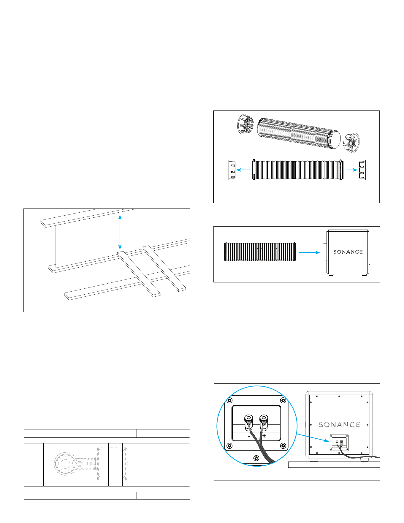
Figure 4: Remove the PVC Port Covers
from the Pipe Tube
18. Position the PPX subwoofer cabinet firmly against
the side of the prepared adjacent joist so that the
cabinet makes full contact.
NOTE: Be sure to test the subwoofer after installation
but before closing/finishing the ceiling to ensure there
is no vibration or rattling from the subwoofer cabinet
within the surface.
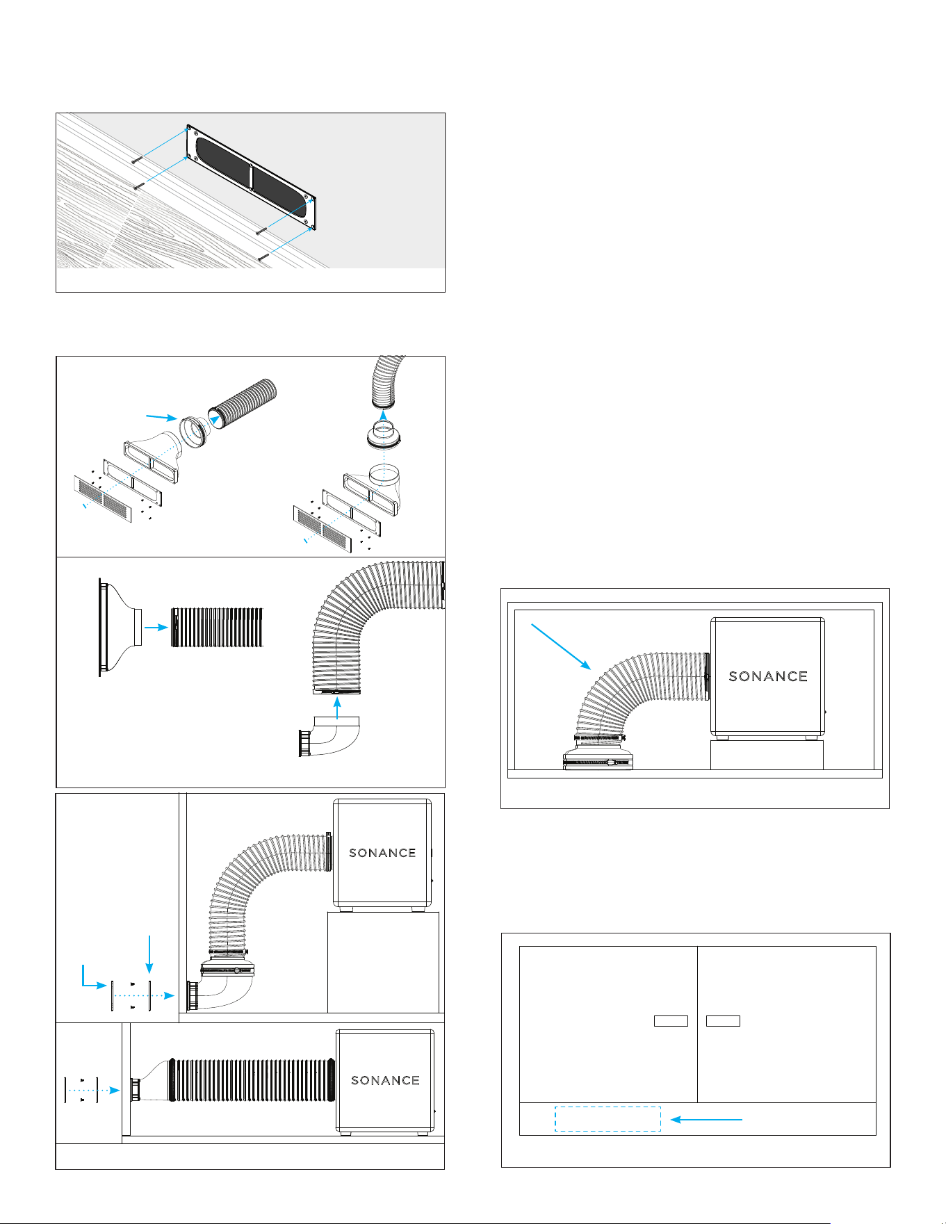
ATTACHING THE PPX PIPE TUBE
19. Remove the PVC port covers from both ends of the
pipe tube (see Figure 4).
Figure 5: Connect Pipe
Tube to Subwoofer
21. Loosen the clamp ring on one end of the pipe tube,
but do not remove. Slide the pipe tube (with the
loosened clamp ring still in place) into position onto
the cabinet opening. Then retighten the clamp ring
to secure the pipe tube onto the cabinet.
NOTE: Make sure the clamp ring is firmly secured to the
subwoofer cabinet so it does not come loose within the
surface once the ceiling is closed and finished.
22. Connect the speaker wire to the subwoofer wire
terminals on the back of the cabinet. The terminals
are spring loaded (see Figure 6).
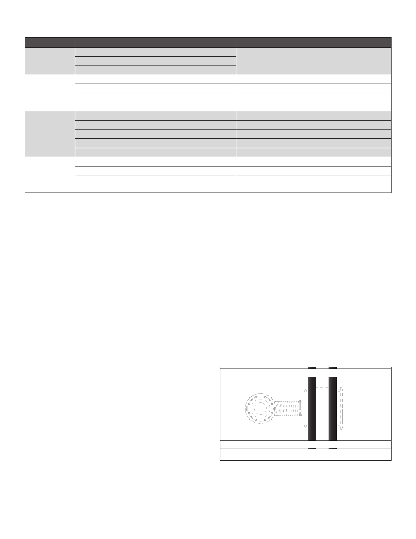
Figure 2: Ceiling Cavity
15. Install the 2x4 boards perpendicular to the joists
within the joist cavity. Secure each end using
structural screws (minimum two per side). Boards
must sit above the bottom plane of the joists. Do
not allow boards to extend below the joists or apply
pressure to the drywall.
16. Prepare the 2x4’s and the joist surfaces within the
cavity with foam tape, insulation tape, or weather
stripping to help prevent unwanted vibration.
17. Place the subwoofer into the prepared 2x4 joist
location, positioning the PPX subwoofer opening
toward the grille location. The PPX subwoofer feet
should straddle the 2x4 boards (see Figure 3).
Figure 3:
Subwoofer
Placement
NOTE: Ensure the enclosure is stable and level, and
that it does not contact drywall or ceiling material
below. Confirm that the port/opening is aligned with
the intended grille location.
10. Proceed to step 19.
BETWEEN JOIST PLACEMENT
11. Measure and cut two 2x4 lumber boards to span
between the adjacent joists at the intended
subwoofer location.
12. Measure the spacing between the rubber feet on
the bottom of the PPX subwoofer. The 2x4 boards
will need to fit when side by side so the feet on
the bottom of the PPX enclosure will straddle the
outside of the boards.
13. Test fit the pipe tube to to confirm it reaches the
finished ceiling plane at the desired grille location.
14. Measure the height from the top of the ceiling
cavity to the top of the 2x4 boards to ensure there
is enough room to place the subwoofer on top of
the boards once they are installed into position (see
Figure 2).
+
-
Figure 6: Subwoofer Wiring
+
-
5
Figure 8: Pull Pipe Tube
Through Cutout in Ceiling
Figure 9: Attach
XPC Connector
XPC Grille
Connector
Figure 11: Attach XPC Grille to XPC Connector
XPC Grille
Connector
XPC Grille
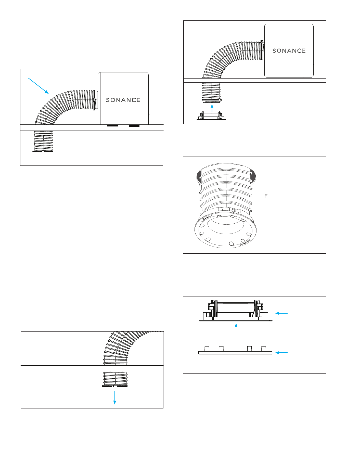
23. Verify that the pipe tube will bend into position in
the desired grille location. Bend the pipe within the
space, aiming the pipe opening downward into the
room. If the pipe tube cannot reach or make the
bend into the desired grille placement, adjustments
will need to be made to relocate the PPX subwoofer
cabinet and PPX rubber straps (see Figure 7).
STANDARD GRILLE FINISH
NOTE: For flush mounted grilles into drywall, skip
to the next section “PREPARING THE CEILING FOR
DRYWALL: FLUSH ROUND OR SQUARE GRILLE” on
page 6. For flush mounted grilles into solid surfaces,
skip to “PREPARING THE CEILING FOR SOLID
SURFACE FLUSH ROUND OR SQUARE GRILLE” on
page 7.
24. Once the PPX subwoofer is in position and the pipe
is securely attached, finish the ceiling surface.
25. After the ceiling is finished, cut the opening in
the ceiling for the grille connector to be installed.
Use the supplied cutout template (included with
the XPC grille connector) to trace and cut to the
dimensions of the appropriate XPC grille connector
for the desired XPC grille size.
26. Retrieve the loose end of the PPX pipe tube in
the ceiling opening and pull it slightly down into
the room (see Figure 8). Loosen the clamp ring to
slide the pipe tube into position on the XPC grille
connector. Retighten the clamp ring to secure the
tube onto the adapter.
Figure 10: Attach XPC
Grille Connector to
Ceiling
Figure 7: Verify the Pipe Tube has Room to Bend
27. Insert the connected pipe and XPC grille connector
into the ceiling opening (see Figure 9).
28. Use a screwdriver or drill on the lowest torque
setting to tighten the screws on the front of the
XPC grille connector to secure it in place within the
ceiling (see Figure 10).
IMPORTANT: Always use low-torque settings when
using a screw gun and go slow; never over tighten.
29. Attach the desired round or square XPC grille into
position on the XPC grille connector, grille sold
separately (see Figure 11).
30. For square grilles, adjustments may be made by
loosening the screws to allow the grille connector
to rotate in the surface until the position of the
grille is properly aligned as desired. No adjustments
required for round grilles.
6
FINISHING THE CEILING: TRUFIG
FLUSH MOUNT
Proceed to these steps after the TRUFIG mounting
platform has been installed and the ceiling surface
has been mudded and sanded. See installation steps
as outlined in the TRUFIG MOUNTING PLATFORM
INSTALLATION GUIDE.
1. Locate the screws on the metal sanding shield and
remove them. Use the keyhole to remove the metal
sanding shield, being careful not to remove the plastic
paint shield.
2. Paint the surface before proceeding.
3. After painting is complete, remove the paint shield
from the mounting platform opening. The paint shield
is a thin, plastic material that is secured around the
perimeter with adhesive, so it should pull away from
the opening easily. The paint shield includes a pre-
cut hole to allow for easy removal using a finger or
pointed object like a screwdriver. Poke through and
pull the paint shield away from the surface.
NOTE: The mounting platform opening includes a small
VX spacer ring that is secured around the rim with
adhesive. Removing the paint shield will reveal the VX
spacer ring. The spacer is labeled “VX SPACER REMOVE
FOR VXQ.”
4. Remove the VX spacer by peeling it away from the
rim.
5. Feel within the surface opening to locate the reserved,
tethered pipe tube. Free it from the tether on the
back of the mounting platform and pull it through to
hang outside of the opening.
6. Pull the loose end of the pipe tube down into the
ceiling opening. Loosen the clamp ring to slide the
pipe tube into position on the XPC grille connector.
Retighten the clamp ring to secure the pipe tube onto
the adapter.
7. Insert the connected pipe tube and XPC grille
connector into the ceiling opening.
8. Use a screwdriver or drill on the lowest torque setting
to tighten the screws on the front of the XPC grille
connector to secure it in place within the ceiling.
IMPORTANT: Always use low-torque settings when using
a screw gun and go slow; never over tighten.
PREPARING THE CEILING FOR
DRYWALL: FLUSH ROUND OR
SQUARE GRILLE
Follow these steps when installing the PowerPipe X
Series subwoofer into the ceiling and finished with a
flush mounted round or square grille.
REQUIRED PARTS
• XPC Grille Connector 4”, 6”, or 8”
• 4”, 6”, or 8” VX TRUFIG Mounting Platform in
Round or Square, 1/2” or 5/8”
• XPC Round or Square Trimless Grille (to match the
selected size above)
• PPX Pipe Adapters as Needed (optional)
• PPX Rubber Straps
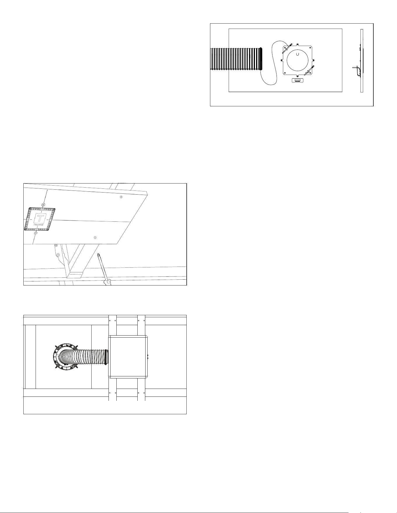
1. Once the PPX subwoofer cabinet is in position,
place the mounting platform in the desired location
for the grille in the ceiling (see Figure 12).
Figure 12: Mount
the Trufig Platform
2. Secure the mounting platform to the joists and
verify that the pipe tube will bend and reach
through the platform opening (see Figure 13).
Figure 13: Mounting Platform Placement
(view from
above/within
the ceiling)
3. The mounting platform has a tie wrap installed
on one of the pierce bridges on the back. Use
this to tether a string from the PowerPipe clamp
ring on the end of the pipe tube for retrieval after
installation (see Figure 14).
NOTE: It is important to wire from the amplifier to
the PPX subwoofer and tether the pipe to the TRUFIG
mounting platform opening BEFORE completing the
mud, sand, and paint for the surface.
Figure 14: Tie Wrap on Mounting Platform
7
Figure 16: Attach
XPC Adapter
XPC Grille
Connector
IMPORTANT: Always use low-torque settings when
using a screw gun and go slow; never over tighten.
8. Attach the desired round or square XPC trimless
grille into position on the XPC grille connector (grille
sold separately).
BEHIND WALL INSTALLATION:
TOEKICK GRILLE
Follow these steps when installing the PPX subwoofer
behind a wall, closet, or large wall cavity, and ported into
the room with a PPX toekick grille.
REQUIRED PARTS
• PPX 90-Degree or Straight Toekick Connector
• PPX Toekick Grille
• PPX Toekick Sub Plate
• Toekick Grille Cutout Template
NOTE: Account for enough spacing to accommodate
the PPX subwoofer cabinet plus the PPX pipe tube that
will be connected to it. The pipe tube will need to bend
toward the wall surface to port into the room. Most
installations will require that the cabinet opening be
placed within 18” of the desired toekick wall opening.
1. Define the desired location and placement behind
the wall or in a large surface cavity. Determine the
desired ported toekick position.
Figure 17: Secure XPC
Adapter to Ceiling
9. Attach the desired round or square XPC grille into
position on the XPC grille connector (grille sold
separately).
PREPARING THE CEILING FOR SOLID
SURFACE TRUFIG FLUSH ROUND OR
SQUARE GRILLE
Follow these steps when installing the PowerPipe X
Series subwoofer into a ceiling made of solid surface
material and finished with a flush mounted round or
square grille.
REQUIRED PARTS
• XPC Grille Connector 4”, 6”, or 8”
• 4”, 6”, or 8”, Round or Square VX TRUFIG Router
Template for Solid Surface Applications
• XPC Round or Square Trimless Grille (to match the
selected size above)
• PPX Pipe Adapters as Needed (optional)
• PPX Rubber Straps
1. Before closing the PPX subwoofer within the ceiling
surface, tether the loose end of the PPX pipe tube
to the inside the surface opening within reach so
the pipe tube can be retrieved after the surface is
finished and complete.
NOTE: It is important to wire from the amplifier to
the PPX subwoofer and tether the pipe tube to the
opening BEFORE closing the surface.
2. Once the PPX subwoofer cabinet is in position,
prepare the ceiling opening.
3. Use the TRUFIG by Sonance router template for the
size and shape of the XPC grille. Follow the steps
outlined within the router template installation
guide to cut the opening into the ceiling surface.
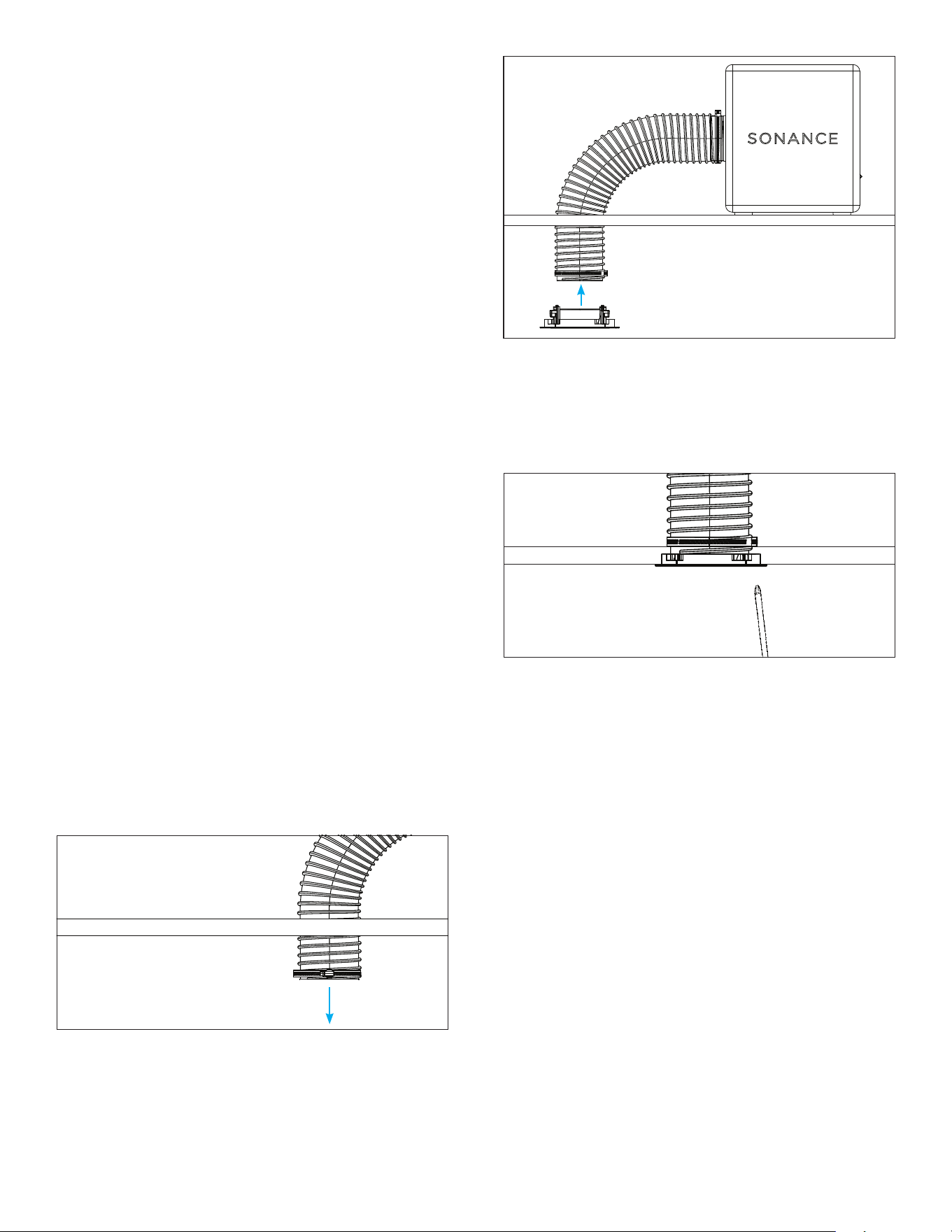
4. Once the ceiling is finished, feel within the surface
opening to locate the pipe tube. Free it from the
tether and pull it through to hang outside of the
opening (see Figure 15).
Figure 15: Pull Pipe Tube
Through Cutout in Ceiling
5. Pull the loose end of the pipe tube down into the
ceiling opening. Loosen the clamp ring to slide the
pipe tube into position on the XPC grille connector.
Retighten the clamp ring to secure the pipe tube
onto the adapter (see Figure 16).
6. Insert the connected pipe tube and XPC grille
connector into the ceiling opening.
7. Use a screwdriver or drill on the lowest torque
setting to tighten the screws on the front of the
XPC grille connector to secure it in place within the
ceiling (see Figure 17).
8
+
-
7. Verify that the pipe tube will bend into position in the
desired toekick grille location. Bend the pipe tube
within the surface, aiming the pipe tube opening into
the room. If the pipe tube cannot reach or make the
bend into the desired grille placement, adjustments
will need to be made to relocate the subwoofer
cabinet until the pipe tube can reach the toekick
connector.
NOTE: For placement that requires a 90-degree bend,
the PPX 90-Degree adapter may be used as an optional
accessory to connect the PPX pipe tube to the toekick.
Do not otherwise alter the length of the PPX pipe tube.
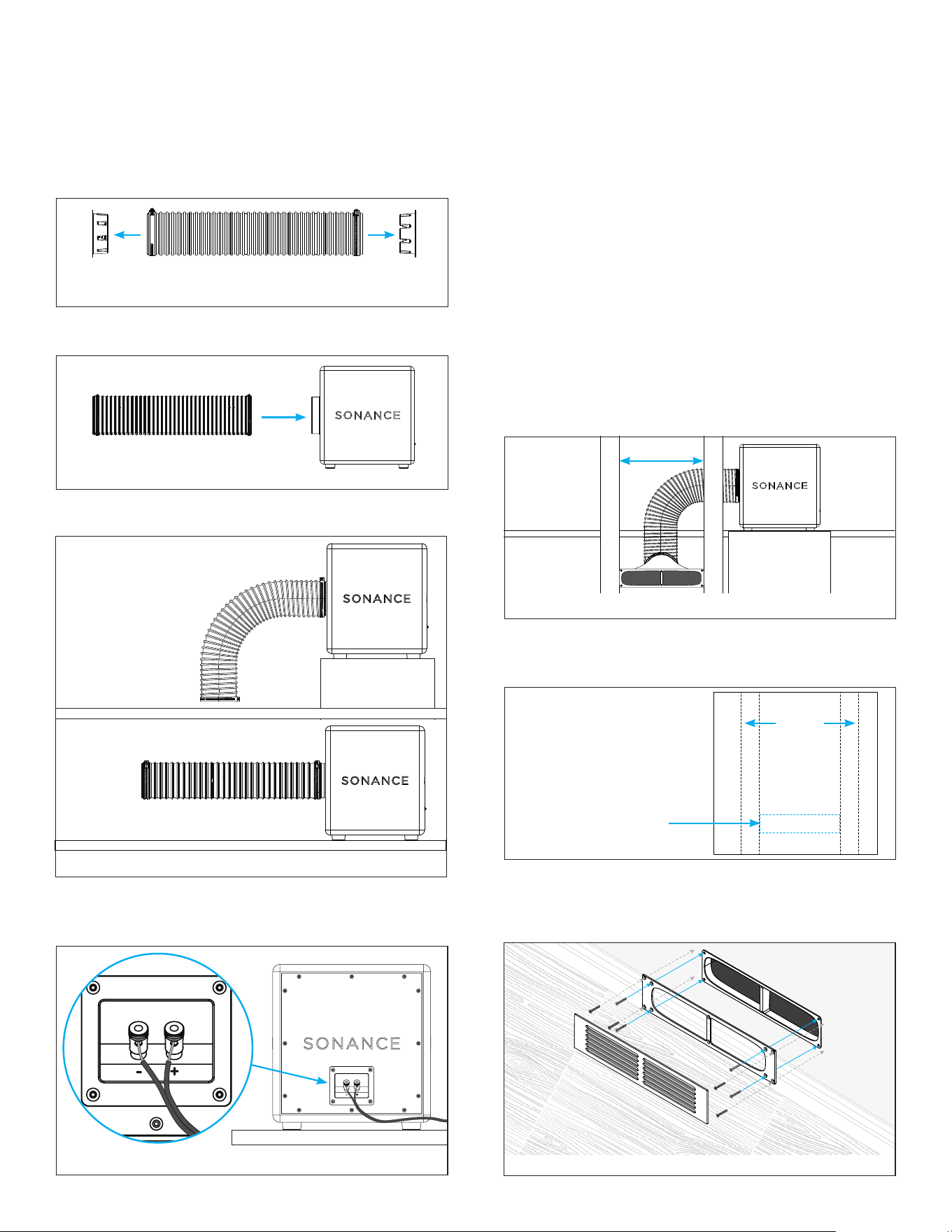
8. Locate the desired grille placement and positioning
near the bottom of the wall or within the baseboard.
9. Identify any studs and plan for the cut to be placed
directly within the stud bay. The PPX toekick
connector and grille will require at least 14.5” of
spacing and will fit into most typical 16” on center
stud bays (see Figure 22).
6. Connect the speaker wire to the subwoofer wire
terminals on the back of the cabinet. The terminals
are spring loaded (see Figure 21).
Figure 21: Subwoofer Wiring
Figure 22: Stud Bay Placement
10. Trace and cut the PPX toekick grille opening. Insert
the toekick connector from within/behind the wall
surface, pressing it flush against the drywall surface.
+
-
11. From the front side of the wall, align and attach the
PPX toekick sub plate to the four corners of the
PPX toekick connector using the four included short
screws (see Figure 24).
Figure 23: Cutout
Template
14.5” min
Cutout Template
Wall
Studs
2. Run two-conductor speaker wire from the amplifier
location to the desired PPX subwoofer location.
3. Remove the PVC port covers from both ends of the
pipe tube. Loosen the clamp ring on each end of the
pipe tube. Slide the pipe tube into position onto the
cabinet opening and then retighten the clamp ring
(see Figure 18).
Figure 18: Remove the PVC Port Covers
from the Pipe Tube
4. Connect the pipe tube to the subwoofer cabinet
(see Figure 19).
Figure 19: Connect Pipe Tube
to Subwoofer
5. Place the PPX subwoofer within the wall location,
onto the ground or sturdy surface (see Figure 20).
Figure 20: Subwoofer Ground Placement
Subwoofer Sturdy
Surface Placement
x
x
x
x
Figure 24: Subwoofer Ground Placement
Outer four (4)
screws, screw into the
drywall/studs.
Inner four (4) screws,
attach toekick sub plate
to the toekick connector.
9
Figure 28: Cabinet Clearance
CABINET INSTALLATION: TOEKICK
GRILLE
Used for mounting the PowerPipe X Series subwoofer
within or behind cabinetry, porting through the toekick
within or near the baseboard of the floor.
REQUIRED PARTS
• PPX Toekick Connector: 90-Degree (PPX-
3.5x16-2-90) is typically used for installations in
baseboard toekicks
• PPX Toekick Grille
• PPX Toekick Sub Plate
• Toekick Grille Cutout Template
CRITICAL DIMENSION: The 90-Degree connector
requires 5” of vertical clearance to accommodate the
height of the toekick connector.
For new cabinet builds, it is easiest to install the toekick
connector and sub plate into the cabinet baseboard by
turning the cabinet upside down to work with full access
to the cabinet’s underside. For installation into cabinets
without access through the bottom, additional cuts will
be required.
1. Verify the cabinet has enough internal clearance
for the PPX subwoofer and that the toekick height
can accommodate the toekick connector and any
required adapters (see Figure 28).
Figure 27: Securing Toekick and Attaching Grille
Toekick
Grille
Toekick
Sub Plate
12. From the front side of the wall, level and secure
the toekick sub plate at the four outer screw holes
using the four included long screws (see Figure 25).
Figure 25: Secure Toekick Sub Plate to Drywall/Stud
13. The toekick sub plate and connector are in position
and ready for the PPX pipe tube to be attached from
behind the wall (see Figures 26 and 27).
4” PIPE TUBE
90-Degree
Toekick
NO ADAPTER IS NEEDED
FOR 6” PIPE TUBES.
6” PIPE TUBE
90-Degree
Toekick
Straight Toekick
Figure 26: Attach Adapter to Pipe Tube
Straight Toekick
Screw through toekick
sub plate into the
drywall/studs
4” to 6”
Adapter
2. Place the PPX subwoofer inside the cabinet to
confirm spacing and positioning for the toekick,
taking care to consider the requirements for the
pipe tube to connect to the subwoofer and bend to
make the connection to the toekick connector and
grille (see Figure 29).
Figure 29: Toekick Cabinet Placement
Toekick Grille
Position
10
7. Position the toekick sub plate over the grille
opening in the cabinet, matching to the toekick
connector opening from inside the cabinet. Align
and attach the PPX toekick sub plate to the four
corners of the PPX toekick connector using the four
included short screws.
Figure 31: Toekick Template Placement
x
x
x
x
Figure 32: Toekick Placement
Outer four (4)
screws, screw into
the cabinet/wood.
Inner four (4) screws,
attach toekick sub plate
to the toekick connector.
9. Now the toekick sub plate and connector are in
position and ready for the PPX pipe tube to be
attached from behind the wall (see Figures 33).
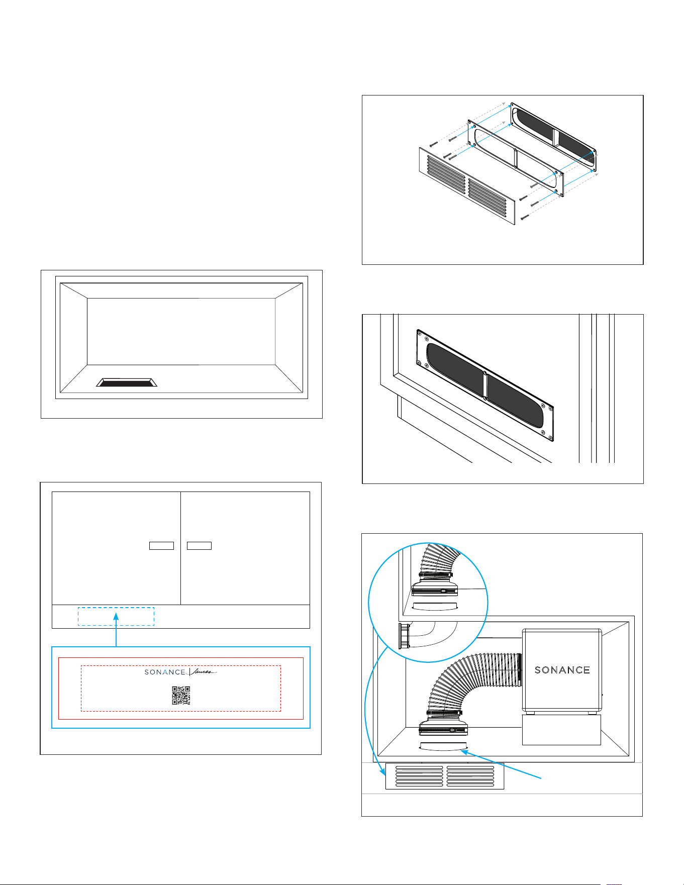
TOE KICK TRIM FOR PPX POWERPIPE
GUIDE AND CUT-OUT TEMPLATE
INSTALLATION GUIDE
1. Position PPX pipe and attached connector from
inside the cabinet or surface and pull through the
surface opening to make it flush to the baseboard/
surface opening.
2. Loosely secure toe kick wall plate to toe kick
connector opening from the front at the six
screw points.
3. Secure plate to the baseboard/surface in four
outermost corners.
4. Attach the magnetic toe kick grille to the installed
toe kick plate.
TOE KICK CUT-OUT TEMPLATE
1. Survey the surface to be cut to avoid wiring,
pipes, and other obstructions that might
interfere with the toe kick and PPX pipe.
2. Use this template to trace an outline in the
desired PPX toe kick location, taking care
for position and level.
3. Cut into the surface along the traced
outline using a keyhole or drywall saw.
4. Proceed with PPX toe kick installation steps
from the PPX PowerPipe Manual.
NOTE: See manual for detailed instructions at:
www.sonance.com.
©2025 Sonance All rights reserved. SONANCE 991 Calle Amanecer, San Clemente, CA 92673 USA • Phone: 949.492.7777 • www.sonance.com
3. Verify that you have 4” or more of vertical space in
the cabinet toekick to be able to cut and install the
PPX toekick connector and grille.
4. Position the toekick connector inside the cabinet
with the toekick grille opening placed against the
base of the cabinet. You may need to remove the
shelf or cut into it to get the connector into position.
5. If unable to access the baseboard/toekick from
within the cabinet, measure and cut a hole in the
bottom shelf within the cabinet large enough to
move the PPX toekick connector into position. For
90-Degree toekick connectors, the hole should be
16” wide and 8” deep, beginning the cut close to the
front of the cabinet shelf and in line with the toekick
grille position. Recommended to cut 1” inward from
the back of the cabinet baseboard (see Figure 30).
Figure 30: Cut a Hole in the Bottom of the Cabinet
6. Mark the front of the cabinet base for the grille
location. Use the toekick grille cutout template to
trace and cut the grille opening in front base of the
cabinet (see Figure 31).
8. From the front side of the cabinet, level and secure
the toekick sub plate to the cabinet at the four
outer screw holes using the four included long
screws (see Figure 32).
Figure 33: Toekick Sub Plate
10. Ensure all connections are sealed with gaskets or
Butyl tape to prevent “hissing” or air leakage into
the cabinet (see Figure 34).
Figure 34: Seal All Edges and Gaps
Seal Edges
11. Attach the magnetic toekick grille into place.
Side view: toekick faces
flush with front of cabinet

11
IMPORTANT NOTES AND BEST
PRACTICES
1. Never cut or alter the length of the PowerPipe
X Series pipe tube. Performance is specifically
tuned to the factory length. Only Sonance
PPX accessories and adapters can be used to
modify pipe angles and diameters as required
for the installation.
2. Always use low-torque settings on drills when
securing adapters to prevent cracking the
plastic or stripping the threads.
3. Use factory specified adapters and extensions
only.
4. Seal all joints carefully to prevent air leaks that
degrade sound quality.
5. Test system after installation to confirm proper
acoustic performance and grille fit.
• PPX Toekick Replacement Grille | 93799
Requires Straight or 90-Degree Toekick Connector
• PPX-8R | 93796
PPX 8” XPC Grille Connector
• PPX-6R | 93795
PPX 6” XPC Grille Connector
• PPX-4R | 93794
PPX 4” XPC Grille Connector
• PPX-6-90 | 93793
PPX 90-Degree Adapter
• PPX-4to6-90-ADAPTER | 93792
PPX 4” to 6” 90-Degree Adapter
• PPX-4to6-STR-ADAPTER | 93791
PPX 4” to 6” Straight Adapter
• PPX-3.5x16-2-STR | 93790
PPX Straight Toekick Connector and Grille
• PPX-3.5x16-2-90 | 93789
PPX 90-Degree Toekick Connector and Grille
• PPX Rubber Straps | 93826
ACCESSORIES

12
PPX8
SKU 93785
UOM Each
Woofer 8” (205mm) anodized aluminum cone, rubber surround, high excursion
Frequency Response 44Hz - 130Hz +/-3dB
Impedance 4 ohms nominal
Sensitivity 91dB SPL
Recommended Power 300 watts
Recommended Amplifiers Blaze Powerzone Connect 1002 | 2004 | 4008 | Sonance DSP 2-750 MKIII
Enclosure Material MDF (Medium Density Fiberboard)
Finish Textured Black
Tube Inside Diameter (Dia) 4.02” (102mm)
Tube Length (L) 21.65” (550mm)
Product Dims w/ Feet (WxHxD) 11.81” x 12.42” x 11.5” (300mm x 315mm x 292mm)
Product Dims w/o Feet (WxHxD) 11.81” x 11.81” x 11.5” (300mm x 300mm x 292mm)
Product Weight 30.56 lbs. (13.86kg)
Shipping Weight 36.38 lbs. (16.5kg)
SONANCE POWERPIPE X SERIES TECHNICAL SPECIFICATIONS
PPX10
SKU 93786
UOM Each
Woofer 10” (254mm) anodized aluminum cone, rubber surround, high excursion
Frequency Response 39Hz - 115Hz +/-3dB
Impedance 4 ohms nominal
Sensitivity 92dB SPL
Recommended Power 400 watts
Recommended Amplifiers Blaze Powerzone Connect 1502 | 3004 | 6008 | Sonance DSP 2-750 MKIII
Enclosure Material MDF (Medium Density Fiberboard)
Finish Textured Black
Tube Inside Diameter (Dia) 4.02” (102mm)
Tube Length (L) 21.65” (550mm)
Product Dims w/ Feet (WxHxD) 12.99” x 13.6” x 11.81” (330mm x 346mm x 300mm)
Product Dims w/o Feet (WxHxD) 12.99” x 12.99” x 11.81” (330mm x 330mm x 300mm)
Product Weight 38.27 lbs. (17.36kg)
Shipping Weight 44.75 lbs. (20.3kg)

13
PPX12
SKU 93787
UOM Each
Woofer 12” (305mm) anodized aluminum cone, rubber surround, high excursion
Frequency Response 34Hz - 100Hz +/-3dB
Impedance 4 ohms nominal
Sensitivity 93dB SPL
Recommended Power 500 watts
Recommended Amplifiers Blaze Powerzone Connect 1502 | 3004 | 6008 | Sonance DSP 2-750 MKIII
Enclosure Material MDF (Medium Density Fiberboard)
Finish Textured Black
Tube Inside Diameter (Dia) 5.98” (152mm)
Tube Length (L) 25.59” (650mm)
Product Dims w/ Feet (WxHxD) 15.75” x 16.36” x 15.16” (400mm x 415mm x 385mm)
Product Dims w/o Feet (WxHxD) 15.75” x 15.75” x 15.16” (400mm x 400mm x 385mm)
Product Weight 55.87 lbs. (25.34kg)
Shipping Weight 64.37 lbs. (29.2kg) Team lift required
SONANCE POWERPIPE X SERIES TECHNICAL SPECIFICATIONS
PPX15
SKU 93788
UOM Each
Woofer 15” (381mm) anodized aluminum cone, rubber surround, high excursion
Frequency Response 29Hz - 90Hz +/-3dB
Impedance 4 ohms nominal
Sensitivity 94dB SPL
Recommended Power 600 watts
Recommended Amplifiers Blaze Powerzone Connect 1502 | 3004 | 6008 | Sonance DSP 2-750 MKIII
Enclosure Material MDF (Medium Density Fiberboard)
Finish Textured Black
Tube Inside Diameter (Dia) 5.98” (152mm)
Tube Length (L) 25.59” (650mm)
Product Dims w/ Feet (WxHxD) 17.72” x 18.33” x 16.93” (450mm x 466mm x 430mm)
Product Dims w/o Feet (WxHxD) 17.72” x 17.72” x 16.93” (450mm x 450mm x 430mm)
Product Weight 68.26 lbs. (30.96kg)
Shipping Weight 79.37 lbs. (36kg) Team lift required

14
PPX8-M
SKU 60665
UOM Each
Woofer 8” (205mm) anodized aluminum cone, rubber surround, high excursion
Frequency Response 44Hz - 130Hz +/-3dB
Impedance 4 ohms nominal
Sensitivity 91dB SPL
Recommended Power 300 watts
Recommended Amplifiers Blaze Powerzone Connect 1002 | 2004 | 4008 | Sonance DSP 2-750 MKIII
Enclosure Material Aircraft Marine Grade Aluminum
Finish Textured Black
Tube Inside Diameter (Dia) 4.02” (102mm)
Tube Length (L) 21.65” (550mm)
Product Dims w/ Feet (WxHxD) 10.64” x 11.25” x 11.56” (270.3mm x 285.8mm x 294mm)*
Product Dims w/o Feet (WxHxD) 10.64” x 10.64” x 11.56” (270.3mm x 270.3mm x 294mm)*
Product Weight 21.14 lbs. (9.60kg)
JAMES POWERPIPE X SERIES TECHNICAL SPECIFICATIONS
PPX10-M
SKU 60667
UOM Each
Woofer 10” (254mm) anodized aluminum cone, rubber surround, high excursion
Frequency Response 39Hz - 115Hz +/-3dB
Impedance 4 ohms nominal
Sensitivity 92dB SPL
Recommended Power 400 watts
Recommended Amplifiers Blaze Powerzone Connect 1502 | 3004 | 6008 | Sonance DSP 2-750 MKIII
Enclosure Material Aircraft Marine Grade Aluminum
Finish Textured Black
Tube Inside Diameter (Dia) 4.02” (102mm)
Tube Length (L) 21.65” (550mm)
Product Dims w/ Feet (WxHxD) 11.7” x 12.31” x 12.18” (297.2mm x 312.7mm x 309.2mm)*
Product Dims w/o Feet (WxHxD) 11.7” x 11.7” x 12.18” (297.2mm x 297.2mm x 309.2mm)*
Product Weight 27.36 lbs. (12.41kg)
*For pigtail option, add 1” (25.4mm) of depth to accommodate water gland

15
PPX12-M
SKU 60668
UOM Each
Woofer 12” (305mm) anodized aluminum cone, rubber surround, high excursion
Frequency Response 34Hz - 100Hz +/-3dB
Impedance 4 ohms nominal
Sensitivity 93dB SPL
Recommended Power 500 watts
Recommended Amplifiers Blaze Powerzone Connect 1502 | 3004 | 6008 | Sonance DSP 2-750 MKIII
Enclosure Material Aircraft Marine Grade Aluminum
Finish Textured Black
Tube Inside Diameter (Dia) 5.98” (152mm)
Tube Length (L) 25.59” (650mm)
Product Dims w/ Feet (WxHxD) 14.59” x 15.2” x 15.3” (370.4mm x 358.9mm x 388.4mm)*
Product Dims w/o Feet (WxHxD) 14.59” x 14.59” x 15.3” (370.4mm x 370.4mm x 388.4mm)*
Product Weight 40.9 lbs (18.55kg) Team lift required
JAMES POWERPIPE X SERIES TECHNICAL SPECIFICATIONS
PPX15-M
SKU 60669
UOM Each
Woofer 15” (381mm) anodized aluminum cone, rubber surround, high excursion
Frequency Response 29Hz - 90Hz +/-3dB
Impedance 4 ohms nominal
Sensitivity 94dB SPL
Recommended Power 600 watts
Recommended Amplifiers Blaze Powerzone Connect 1502 | 3004 | 6008 | Sonance DSP 2-750 MKIII
Enclosure Material Aircraft Marine Grade Aluminum
Finish Textured Black
Tube Inside Diameter (Dia) 5.98” (152mm)
Tube Length (L) 25.59” (650mm)
Product Dims w/ Feet (WxHxD) 16.55” x 17.16” x 17.08” (420.4mm x 435.9mm x 433.8mm)*
Product Dims w/o Feet (WxHxD) 16.55” x 16.55” x 17.08” (420.4mm x 420.4mm x 433.8mm)*
Product Weight 50 lbs. (22.68kg) Team lift required
*For pigtail option, add 1” (25.4mm) of depth to accommodate water gland

16
©2026 Sonance. All rights reserved. Sonance is a registered trademark of Dana Innovations. Due to continuous product improvement, all features and
specifications are subject to change without notice. For the latest Sonance product specification information visit our website: www.sonance.com
991 Calle Amanecer • San Clemente, CA 92673 USA • PHONE: (949) 492-7777 03.05.2026
LIMITED FIVE (5) YEAR WARRANTY AND TWO (2) YEAR WARRANTY
Sonance warrants to the first end-user purchaser that this Sonance-brand product (“Product”), when purchased from an authorized
Sonance Dealer/Distributor, will be free from defective workmanship and materials for five (5) years for Sonance PPX8, PPX10, PPX12,
and PPX15 models, and two (2) years for James Marine PPX8-M, PPX10-M, PPX12-M, and PPX15-M models. PPX grilles and adapter
accessories are warranted for five (5) years. Sonance will at its option and expense either repair the defect or replace the Product with a
new or remanufactured Product or a reasonable equivalent.
EXCLUSIONS: TO THE EXTENT PERMITTED BY LAW, THE WARRANTY SET FORTH ABOVE IS IN LIEU OF, AND EXCLUSIVE OF, ALL
OTHER WARRANTIES, EXPRESS OR IMPLIED, AND IS THE SOLE AND EXCLUSIVE WARRANTY PROVIDED BY SONANCE. ALL OTHER
EXPRESS AND IMPLIED WARRANTIES, INCLUDING THE IMPLIED WARRANTIES OF MERCHANTABILITY, IMPLIED WARRANTY OF
FITNESS FOR USE, AND IMPLIED WARRANTY OF FITNESS FOR A PARTICULAR PURPOSE ARE SPECIFICALLY EXCLUDED. NO ONE
IS AUTHORIZED TO MAKE OR MODIFY ANY WARRANTIES ON BEHALF OF SONANCE.
The warranty stated above is the sole and exclusive remedy and Sonance’s performance shall constitute full and final satisfaction of all
obligations, liabilities and claims with respect to the Product.
IN ANY EVENT, SONANCE SHALL NOT BE LIABLE FOR CONSEQUENTIAL, INCIDENTAL, ECONOMIC, PROPERTY, BODILY INJURY, OR
PERSONAL INJURY DAMAGES ARISING FROM THE PRODUCT, ANY BREACH OF THIS WARRANTY OR OTHERWISE.
This warranty statement gives you specific legal rights, and you may have other rights which vary from state to state. Some states do
not allow the exclusion of implied warranties or limitations of remedies, so the above exclusions and limitations may not apply. If your
state does not allow disclaimer of implied warranties, the duration of such implied warranties is limited to period of Sonance’s express
warranty.
Your Product Model and Description: Sonance PowerPipe X Series Subwoofer PPX8 | PPX10 | PPX12 | PPX15 | PPX8-M | PPX10-M |
PPX12-M | PPX15-M.
Additional Limitations and Exclusions from Warranty Coverage: The warranty described above is non-transferable, applies only to the
initial installation of the Product, does not include installation of any repaired or replaced Product, does not include damage to allied
or associated equipment which may result for any reason from use with this Product, and does not include labor or parts caused by
accident, disaster, negligence, improper installation, misuse (e.g. overdriving the amplifier or speaker, excessive heat or cold or humidity,
outdoor installation), or from service or repair which has not been authorized by Sonance.
Obtaining Authorized Service: To qualify for the warranty, you must contact your authorized Sonance Dealer/Installer or call Sonance
Customer Service at (949) 492-7777, must obtain a return merchandise number (RMA), and must deliver the Product to Sonance
shipping prepaid during the warranty period, together with the original sales receipt, or invoice or other satisfactory proof of purchase.
In order to initiate a warranty claim:
1. Contact Sonance Technical Support with a description of the fault, the product’s serial number and the date of purchase from an
authorized Sonance dealer at: [email protected]
2. Sonance Technical Support will follow-up and may request additional troubleshooting.
3. Once a determination has been made on the fault, Sonance Customer Service will follow-up by email. Please have a scanned copy of
your product’s sales invoice ready to send upon request to document the subwoofer’s warranty status.
4. Sonance Customer Service will provide an RMA number to be included on the shipping label of the packaging. Please send the
product back in its original factory carton, which has been specifically designed to protect it during transit.
Contact us at: https://www.sonance.com/company/contact
